key technologies in 5g: network architecture · key technologies in 5g: network architecture saeed...
TRANSCRIPT
Key Technologies in 5G: Network Architecture
Saeed Sheikhzadeh, Mohammad Reza Javan ∗
Abstract—To address the continuously increasing demandfor high data rates, beside air interface technologies, thereare requirements to introduce new and effective ways todesign architecture of networks. This paper proposes severaltechnologies which can be used as promising candidates tochange the future of wireless communication architectureespecially in Fifth generation (5G) wireless network. In thisarticle, we discuss various promising cellular architecturessuch as full duplex communication, device-to-device com-munication, mobile femtocell, visible light communicationand visualization in 5G.
Index Terms—5G, network architecture, full duplex,device-to-device, mobile femtocell, visible light communic-ation, NFV, SDN, C-RAN.
I. INTRODUCTION
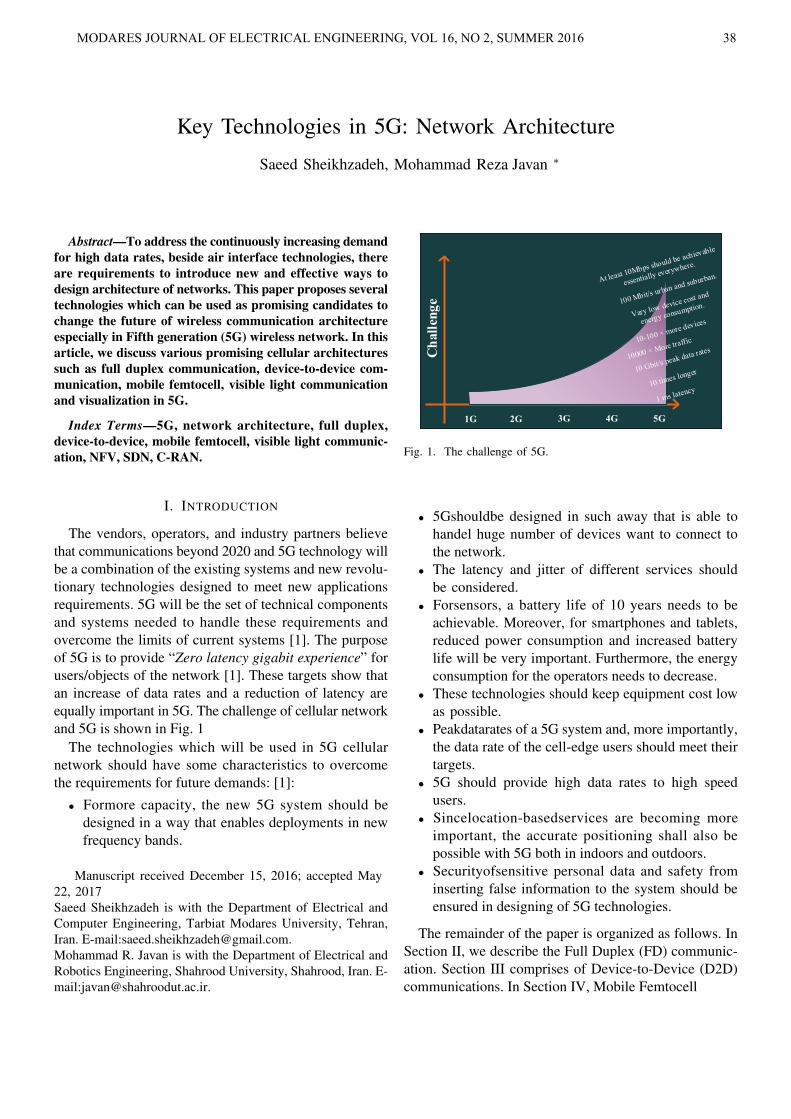
The vendors, operators, and industry partners believethat communications beyond 2020 and 5G technology willbe a combination of the existing systems and new revolu-tionary technologies designed to meet new applicationsrequirements. 5G will be the set of technical componentsand systems needed to handle these requirements andovercome the limits of current systems [1]. The purposeof 5G is to provide “Zero latency gigabit experience” forusers/objects of the network [1]. These targets show thatan increase of data rates and a reduction of latency areequally important in 5G. The challenge of cellular networkand 5G is shown in Fig. 1
The technologies which will be used in 5G cellularnetwork should have some characteristics to overcomethe requirements for future demands: [1]:
• Formore capacity, the new 5G system should bedesigned in a way that enables deployments in newfrequency bands.
Manuscript received December 15, 2016; accepted May22, 2017Saeed Sheikhzadeh is with the Department of Electrical andComputer Engineering, Tarbiat Modares University, Tehran,Iran. E-mail:[email protected] R. Javan is with the Department of Electrical andRobotics Engineering, Shahrood University, Shahrood, Iran. E-mail:[email protected].
Challenge
1G 2G 3G 4G 5G
Fig. 1. The challenge of 5G.
• 5Gshouldbe designed in such away that is able tohandel huge number of devices want to connect tothe network.
• The latency and jitter of different services shouldbe considered.
• Forsensors, a battery life of 10 years needs to beachievable. Moreover, for smartphones and tablets,reduced power consumption and increased batterylife will be very important. Furthermore, the energyconsumption for the operators needs to decrease.
• These technologies should keep equipment cost lowas possible.
• Peakdatarates of a 5G system and, more importantly,the data rate of the cell-edge users should meet theirtargets.
• 5G should provide high data rates to high speedusers.
• Sincelocation-basedservices are becoming moreimportant, the accurate positioning shall also bepossible with 5G both in indoors and outdoors.
• Securityofsensitive personal data and safety frominserting false information to the system should beensured in designing of 5G technologies.
The remainder of the paper is organized as follows. InSection II, we describe the Full Duplex (FD) communic-ation. Section III comprises of Device-to-Device (D2D)communications. In Section IV, Mobile Femtocell
MODARES JOURNAL OF ELECTRICAL ENGINEERING, VOL 16, NO 2, SUMMER 2016 38
MODARES JOURNAL OF ELECTRICAL ENGINEERING, VOL 16, NO 2, SUMMER 2016 39
(MFemtocell) is presented. Section V discuss aboutVisible Light Communication (VLC). Section VI givesthe detailed description of Software Defined Networking(SDN), Network Function Visualization (NFV) and theCloud Radio Access Network (C-RAN). Finally, weconclude our paper in Section VII.
II. FULL DUPLEX
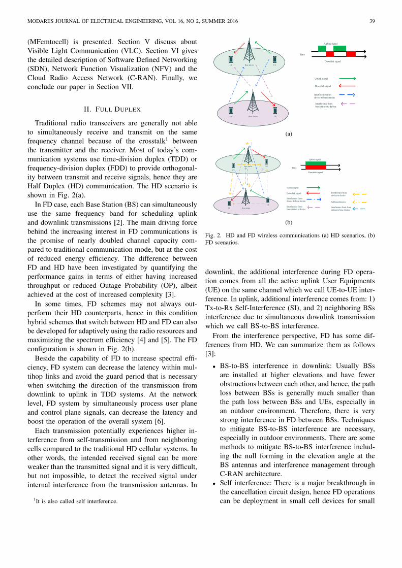
Traditional radio transceivers are generally not ableto simultaneously receive and transmit on the samefrequency channel because of the crosstalk1 betweenthe transmitter and the receiver. Most of today’s com-munication systems use time-division duplex (TDD) orfrequency-division duplex (FDD) to provide orthogonal-ity between transmit and receive signals, hence they areHalf Duplex (HD) communication. The HD scenario isshown in Fig. 2(a).
In FD case, each Base Station (BS) can simultaneouslyuse the same frequency band for scheduling uplinkand downlink transmissions [2]. The main driving forcebehind the increasing interest in FD communications isthe promise of nearly doubled channel capacity com-pared to traditional communication mode, but at the costof reduced energy efficiency. The difference betweenFD and HD have been investigated by quantifying theperformance gains in terms of either having increasedthroughput or reduced Outage Probability (OP), albeitachieved at the cost of increased complexity [3].
In some times, FD schemes may not always out-perform their HD counterparts, hence in this conditionhybrid schemes that switch between HD and FD can alsobe developed for adaptively using the radio resources andmaximizing the spectrum efficiency [4] and [5]. The FDconfiguration is shown in Fig. 2(b).
Beside the capability of FD to increase spectral effi-ciency, FD system can decrease the latency within mul-tihop links and avoid the guard period that is necessarywhen switching the direction of the transmission fromdownlink to uplink in TDD systems. At the networklevel, FD system by simultaneously process user planeand control plane signals, can decrease the latency andboost the operation of the overall system [6].
Each transmission potentially experiences higher in-terference from self-transmission and from neighboringcells compared to the traditional HD cellular systems. Inother words, the intended received signal can be moreweaker than the transmitted signal and it is very difficult,but not impossible, to detect the received signal underinternal interference from the transmission antennas. In
1It is also called self interference.
Base stat ion
Base stat ion
UE
UE
Uplink signal
Downlink signal
Interference from
device to base station
Interference from
base station to device
Uplink signal
Downlink signal
Time
UE
UE
(a)
Base stat ion
Base stat ion
UE
UE
Uplink signal
Downlink signal
Interference from
device to base station
Interference from
base station to device
Uplink signal
Downlink signal
TimeUE
Interference from
device to device
Self-interference
Interference from base
station to base stationUE
(b)
Fig. 2. HD and FD wireless communications (a) HD scenarios, (b)FD scenarios.
downlink, the additional interference during FD opera-tion comes from all the active uplink User Equipments(UE) on the same channel which we call UE-to-UE inter-ference. In uplink, additional interference comes from: 1)Tx-to-Rx Self-Interference (SI), and 2) neighboring BSsinterference due to simultaneous downlink transmissionwhich we call BS-to-BS interference.
From the interference perspective, FD has some dif-ferences from HD. We can summarize them as follows[3]:
• BS-to-BS interference in downlink: Usually BSsare installed at higher elevations and have fewerobstructions between each other, and hence, the pathloss between BSs is generally much smaller thanthe path loss between BSs and UEs, especially inan outdoor environment. Therefore, there is verystrong interference in FD between BSs. Techniquesto mitigate BS-to-BS interference are necessary,especially in outdoor environments. There are somemethods to mitigate BS-to-BS interference includ-ing the null forming in the elevation angle at theBS antennas and interference management throughC-RAN architecture.
• Self interference: There is a major breakthrough inthe cancellation circuit design, hence FD operationscan be deployment in small cell devices for small
SHEIKHZADEH Et al. KEY TECHNOLOGIES IN 5G: NETWORK ARCHITECTURE 40
cell deployment, where the smaller coverage areamakes it a more suitable environment to deploy FDradios.
• User to user in uplink interference: Since this typeof interference depends on the location as wellas the transmission power of UEs, an intelligentcoordination mechanism is needed. The goal of thecoordination is to select those UEs for simultaneoustransmission such that their rate/power allocationwould create less interference on each other.
Excessive SI may even result in reduced capacityfor FD systems that falls below that of HD systems.Compared to the weak received signal of interest, theSI signal can have 60–100 dB higher power. Therefore,the SI signal must be attenuated significantly to allowdetection of the actual received signal and enable FDcommunications in the first place [6]. It is important that,for obtaining the acceptable throughput, the SI level afterperforming SI suppression be at least 3 dB lower thanthe noise level. Consensus reached by both industry andacademia shows that it is critical to perform efficientSI suppression/cancellation in implementing radical FDcommunication systems [5] and [7]. There are twomethods for omitting the self-interference: 1) passiveisolation [8], and 2) active cancellation [9].
To decrease the complexity of active cancellationtechniques and circles, the passive isolation betweenthe transmitter and receiver can be used. This leads tothe power of the SI leaking to the receiver becomessmall and no complicated active cancellation is needed.When the transmit and receive antennas are separated,by increasing the spacing between the antennas or usingdifferent polarizations, the electromagnetic isolation be-tween the antennas can be improved in a straightforwardmanner and resulting in lower SI power. Due to thesetechniques are passive in nature, they require no trackingof the SI signal and its possible distortion while still canprovide a significantly decrease in the amount of SI. Wecan mention some passive isolation methods such as theuse of band-gap structures as high-impedance surfacesand inductive loops, the port-to-port isolation betweenthe antenna feeds, connecting lumped elements betweenantenna feeds and resonant structures like wavetraps [6].
Active SI cancellation is used to help passive antennabased techniques to mitigate the SI effects. Active can-celation acts in two steps: first at the input of the receiverchain, and then after the Analog-to-Digital Conversion(ADC) [6]. The first step is required in order to preventthe complete saturation of the receiver components andADC. The second step is performed to attenuate theremaining SI signal below the noise floor.
Theoretically, an FD system has an infinite dynamic
range and perfect channel estimation can perfectlyeliminate the SI signal. However in practice, due tothe hardware limitations such as transmit/receive signalquantization, nonlinearities, and In-phase and Quadrature(I/Q) mismatch, system is unable to reach the theoreticalperformance [5].
FD is very useful and applicable for cognitive radionetworks. The secondary users sense the spectrum andtransmit whenever the spectrum holes are detected con-tinuously which is very critical. Cognitive radio networkscan use the potential to achieve simultaneous sensing andtransmission with use of FD systems. Secondary userswith FD radios can sense the target spectrum band ineach time slot and determine if the primary users usethe spectrum or not, and at the same time, can transmitdata or decide to keep silent based on the sensing results[10].
III. DEVICE-TO-DEVICE COMMUNICATIONS
Generally, D2D communication is a type of commu-nications in which devices communicate to each otherwithout any communications infrastructures. D2D com-munication introduces new usage models based on theadjacency of users including social networking appli-cations, peer-to-peer content sharing, and public safetycommunications in the absence of network coverage.Since D2D network realize ad hoc mesh network, hence,can be of critical use in natural disasters. In a criticalsituation, an urgent communication network can be setup using D2D functionality in a short time, replac-ing the damaged communication network and Internetinfrastructure. In the traditional cellular networks, acentral entity is responsible for coordinating the com-munications between the network devices through theBS meaning that no direct communications betweendevices is allowed. However, emerging context-awareapplication which needs location discovery and com-munications between neighboring devices makes D2Dcommunications necessary for future wireless networksas well as 5G. In D2D communications, two neighboringdevices communicate with each other over the cellularbandwidth without or with little BS coordination [11].
D2D functionality will increase the coverage, offloadbackhaul, provide the fallback connectivity, and increasethe spectrum utilization, capacity per area, and batterylife. One of the advantages of D2D functionality isto reduce some load of the network in a local areasuch as a stadium or a big mall by allowing directtransmission among cell phones and other devices. Theload balancing and load management can be optimizedby network and device pro-active caching of commoninformation and offloading the devices to establish direct
SHEIKHZADEH Et al. KEY TECHNOLOGIES IN 5G: NETWORK ARCHITECTURE
MODARES JOURNAL OF ELECTRICAL ENGINEERING, VOL 16, NO 2, SUMMER 2016 41
links. Indeed, D2D communication has been used inthe ad-hoc and personal area networking technologiesin unlicensed spectrum bands e.g., Industrial, Scientific,and Medical (ISM) bands. Although this type of com-munication requires less control, it has certain shortagesuch as limited content sharing, no point-to-multipointlinks, synchronization issues, authentication, interferenceissue, and security concerns [12]. The spectral efficiency,throughput per area, energy efficiency, battery life, andlatency can be achieved by reducing the distance betweennodes in D2D communication. The coverage can beenhanced by other devices cooperation which can bethe only communication in case of poor or no coverage,coverage holes, and emergency situation. Indeed, whenthe distance between the transmitter and the receiver islarge, the channel attenuation will be also high leadingto poor received signal. Cooperative communication isa promising technology which can be used to improvethe channel quality. In this type of communications,a third node called relay station is used to help thecommunications quality improves. One solution is toinstal relay stations which could be expensive. However,with D2D functionality, some (idle) users could take theresponsibility of relaying the information. Hence, fullpotential of cooperation can be realized only throughthe implementation of device relaying. Generally, D2Dcommunications are commonly used in:
• Safety applications and disaster scenarios.• Novel commercial Proximity Services (ProSe) sce-
narios.• Network traffic offloading.• Industrial automation and machine-to-machine
communication.
In 5G, D2D communication is considered as anothertier where the set of devices cooperate with each otherto dramatically increase the network capacity by eitherreusing the same spectrum as the macro cell or by usingunlicensed spectrum. In the D2D communications, theoperator might have different levels of control (full,partial, or no control) over the resource allocation amongthe source, the destination, and the relaying devices.Therefore, the D2D communications is classified intofour main types as follows [11]:
• Devices communicate directly with each other andthe operator acts as supervisor (Fig. 3(c)).
• Devices communicate with the help of other deviceas a relay and the operator acts as supervisor toestablish and control the links (Fig. 3(a) and Fig.3(b)).
• Devices communicate directly with each other andthe operator is not involved into the process of es-
tablishing and controlling the links and the devicesare responsible for this task (Fig. 4(b).
• Devices communicate with the help of other deviceas a relay and the operator is not involved into theprocess of establishing and controlling the links anddevices are responsible for this task (Fig. 4(a)).
In the two first cases, the resource allocation isperformed by the BS. Therefore, the BS can handlethe problem of the interference management using cen-tralized methods. However, in the two last cases, theresource allocation between devices is done withoutcentralized entity to supervise. Operating in the samelicensed band, D2D communication has an impact onother existed users which use licensed band. Hence toreduce impact on the performance of other users, thesmart interference management strategies and appropri-ate resource allocation schemes needs to be considered.The ad-hoc mode of D2D communication in the licensedspectrum (two last cases) offers limited applicationssimilar to the unlicensed counterpart. However, whenthe network infrastructure acts as the supervisor, D2Dcommunication in the licensed band has many applica-tions such as social networking, video sharing, mobilerelaying, and gaming, as well as many benefits suchas traffic offloading, capacity enhancement (frequencyreuse), extended cellular coverage, improved energy ef-ficient communication [12].
There are two access schemes in D2D communication,closed access, and open access [13]. In closed access, thedevice which works as relay, has a trust list containingthe name of the users which can connect. The list oftrusted devices can contain the users in a neighborhoodor workplace that know each other, or the users thathave been authenticated via a trusted party such as anorganization. In open access scheme, each device can actas a relay for other devices without any restrictions. Inthis case, the security is a challenging issue and must beconsidered carefully.
There are three main options for the integration ofD2D into the cellular networks [14]:
• D2D communication can be with network-controlled or not: In network-controlled approach,infrastructure nodes (BSs and control entities)play a central role in establishing, arbitrating, andmanaging D2D connections. The infrastructureperforms the fundamental tasks such as spectrummanagement, security, information brokering, andmobility management.
• D2D can work in both the in-band and out-of-bandfashions: In-band refers to the D2D communicationtype whose traffic uses the same licensed frequen-

SHEIKSHEIKHZADEH Et al. KEY TECHNOLOGIES IN 5G: NETWORK ARCHITECTUREHZADEH Et al. KEY TECHNOLOGIES IN 5G: NETWORK ARCHITECTURE
42
Base station
Source
Relaying device
Control link
User data link
Relaying device
(a)
Base station
Source
Relaying device
Control link
User data link
Relaying device
Distination
(b)
Base station
Source
Distination
Control link
User data link
(c)
Fig. 3. D2D communications (a) device relaying communication withoperator controlled link establishment for transmitting the data fromBS, (b) Device relaying communication with operator controlled linkestablishment for transmitting the data from other user, (c) direct D2Dcommunication with operator controlled link establishment [11].
cies as those used by the ordinary D2D traffic. Themain benefit of this approach is the higher degreeof control that the operators retain on who trans-mits and how which could limits the interference.Cooperation among users in this approach becomesmore easy to enforce and check. Furthermore, inthe view of terminals, there is no need to carryadditional radio interfaces. The opposite approach,i.e., the out-of-band D2D, is used to offload cellularnetworks through other networks.
• D2D can work in overlay or underlay fashion:Overlay fashion refers to the fact there is no part
Base station
Source
Relaying device
Control link
User data link
Relaying device
Distination
(a)
Base station
Source
Control link
User data link
Distination
(b)
Fig. 4. (a) device relaying communication with device controlled linkestablishment (b) direct D2D communication with device controlledlink establishment.
of the spectrum specifically reserved to that D2Dcommunication and it same as primary users incognitive radio. When networks operate in under-lay fashion, D2D transfers and traditional cellularcommunications share the same radio resourcesand are scheduled within the cellular bands in anopportunistic fashion same as secondary users incognitive radio.
IV. MOBILE FEMTOCELL
The use of femtocells has become a promising way toimprove the throughput of the wireless communicationnetworks due to the ability to absorb the indoor trafficand reduce the originating traffic from the outdoor BSs.The deployment of Femtocell Access Points (FAPs) inmacrocells’ area has several benefits for operators andsubscribers who access to the FAPs for getting service.From the operators’ point of view, the advantages ofFAPs’ deployment are reducing the network deploymentcost, increasing the spectrum efficiency, and offloadingthe data traffic originating from the existing macrocell inthe indoor environments. From the subscribers’ perspec-tive, they can achieve a high Signal to Interference PlusNoise Ratio (SINR) leading to substantially improvedindoor coverage and high throughput [15] and [16].
SHEIKHZADEH Et al. KEY TECHNOLOGIES IN 5G: NETWORK ARCHITECTURE
MODARES JOURNAL OF ELECTRICAL ENGINEERING, VOL 16, NO 2, SUMMER 2016 43
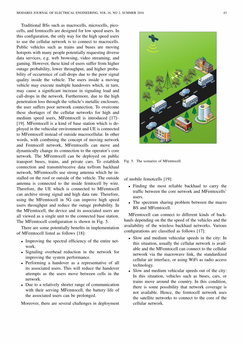
Traditional BSs such as macrocells, microcells, pico-cells, and femtocells are designed for low speed users. Inthis configuration, the only way for the high speed usersto use the cellular network is to connect to macrocells.Public vehicles such as trains and buses are movinghotspots with many people potentially requesting diversedata services, e.g. web browsing, video streaming, andgaming. However, these kind of users suffer from higheroutage probability, lower throughput, and higher proba-bility of occurrence of call-drops due to the poor signalquality inside the vehicle. The users inside a movingvehicle may execute multiple handovers which, in turn,may cause a significant increase in signaling load andcall-drops in the network. Furthermore, due to the highpenetration loss through the vehicle’s metallic enclosure,the user suffers poor network connection. To overcomethese shortages of the cellular networks for high andmedium speed users, MFemtocell is introduced [17]–[19]. MFemtocell is a kind of base station which is de-ployed in the vehicular environment and UE is connectedto MFemtocell instead of outside macrocellular. In otherwords, with combining the concept of moving networkand Femtocell network, MFemtocells can move anddynamically change its connection to the operator’s corenetwork. The MFemtocell can be deployed on publictransport buses, trains, and private cars. To establishconnection and transmit/receive data to/from backhaulnetwork, MFemtocells use strong antenna which be in-stalled on the roof or outside of the vehicle. The outsideantenna is connected to the inside femtocell by wire.Therefore, the UE which is connected to MFemtocellcan archive strong signal and high data rate. Therefore,using the MFemtocell in 5G can improve high speedusers throughput and reduce the outage probability. Inthe MFemtocell, the device and its associated users areall viewed as a single unit to the connected base station.The MFemtocell configuration is shown in Fig. 5.
There are some potentially benefits in implementationof MFemtocell listed as follows [18]:
• Improving the spectral efficiency of the entire net-work.
• Signaling overhead reduction in the network forimproving the system performance.
• Performing a handover as a representative of allits associated users. This will reduce the handoverattempts as the users move between cells in thenetwork.
• Due to a relatively shorter range of communicationwith their serving MFemtocell, the battery life ofthe associated users can be prolonged.
Moreover, there are several challenges in deployment
Fig. 5. The scenarios of MFemtocell.
of mobile femotcells [19]:
• Finding the most reliable backhaul to carry thetraffic between the core network and MFemtocells’users.
• The spectrum sharing problem between the macroBS and MFemtocell.
MFemtocell can connect to different kinds of back-hauls depending on the the speed of the vehicles and theavailability of the wireless backhaul networks. Variousconfigurations are classified as follows [17]:
• Slow and medium vehicular speeds in the city: Inthis situation, usually the cellular network is avail-able and the MFemtocell can connect to the cellularnetwork via the macrowave link, the standardizedcellular air interface, or using WiFi as radio accesstechnology.
• Slow and medium vehicular speeds out of the city:In this situation, vehicles such as buses, cars, ortrains move around the country. In this condition,there is some possibility that network coverage isnot available. Hence, the femtocell network usesthe satellite networks to connect to the core of thecellular network.

SHEIKHZADEH Et al. KEY TECHNOLOGIES IN 5G: NETWORK ARCHITECTURE 44
• High vehicular speeds: For this case, due to fre-quently network handover, connecting to the macro-cell is not an effective way for backhauling theMFemtocell traffic. Therefore, the satellite networkis the best possible solution.
• In ship and airplane: In this situation the onlysolution is satellite.
V. VISIBLE LIGHT COMMUNICATION
The increased wireless data traffic is creating pressureon the dwindling Radio Frequency (RF) spectrum. Thispressure drives the need for alternative technologies.The VLC also known as Li-Fi or Optical WirelessCommunication (OWC) [20], is a new technology whichis introduced to overcome the concern about spectrumscarcity. VLC generally uses fast switching Light Emit-ting Diodes (LEDs) as its source. On the receiver side,photodiodes is used to convert the optical signals toelectrical signals. These sources have the ability toprovide illumination and communication for short rangeindoor links simultaneously [21]. This means that VLCenables systems that illuminate and at the same timeprovide broadband wireless data connectivity.
VLC systems rely on two disjoint industries: thebroadband wireless communications industry and thecommercial lighting industry. Since in practice, VLCdevices can become marketable, they must have ability toprovide high quality lighting and reliable data communi-cation [22]. On the other hand, due to good light quality,low energy consumption, small size, and long lifetime,LED-based illumination devices are a significant substi-tution to traditional incandescent-based and fluorescent-based illumination devices in the near future and theywill be deployed in many countries around the world asindoor illumination, display devices, and traffic lights. Atthe present time, with huge growth in communicationand illumination technology, the notable properties ofLED make it particularly proper for wireless communi-cation. On the transmitter side, to achieve high data rate,the signal by on-off keying modulation is modulated. Onthe receiver side, the photodiodes are used to convert theoptical signals to electrical signals at very high rates.In sum, it is appropriate combining illumination deviceswith wireless communication devices to achieve bothgreen communication and energy-saving illumination.Since LED is safe for eyes and inexpensive, it is moresuitable for indoor applications than laser. However theavailable bandwidth is less than that of laser, whichcan achieve a data rate up to Gbps. Unlike the highlyfocused laser, LED is a diffuse source that can provideadequate coverage in a room by placing lots of smallLED elements on a panel. Furthermore, the direction
and placement of LED elements are determined theefficiency of illumination and communication [20]. Anoptical attocell covers an area of 1–10m2 and distancesof about 3 m [22].
By combining the data on the visible LED’s lightway above the human eye’s fusion rate, illumination aswell as communication can be realized simultaneously.Recently, due to the fact that the visible light spectrumoffers a lot of untamed free bandwidth, VLC has en-grossed much attention in the wireless communicationsystems. Moreover, VLC can be used to provide ultra-fast speed wireless communications. Although VLC maynot be good solution for large cellular wireless com-munication, it can be considered as supplementary usedfor small cell wireless coverage as hot spots under largeheterogeneous networks. VLC was originally developedfor indoor last mile wireless service delivery. Moreover,it is hard to be used for mobile communications dueto the narrow beamwidth in light waves. With usingthe visible light spectrum, VLC can easily reach up toseveral Gbps and can have important role in 5G tech-nology [23]. Sophisticated modulation schemes, such asthe Optical Orthogonal Frequency Division Modulation(OOFDM) and simple On-Off Keying (OOK) and PulsePosition Modulation (PPM) can be used to increased thedata rate [24]. Moreover, Multiple-Input Multiple-Output(MIMO) technology and Red-Green-Blue (RGB)-LEDwith Wavelength Division Multiplexing (WDM) are ex-ploited to achive ambitiously Gbps transmissions datarate. VLC uses unregulated spectrum, specifically from428 to 750 THz, which provides huge communicationbandwidth to deliver services such as large files andsuper high definition video transfer [20]. Moreover, theultra wide bandwidth is also more robust to multipathfading in various environments. It has to be notedthat VLC is not subject to fast fading effects as thewavelength is significantly smaller than the detector area[22]. The scenario of VLC is shown in Fig. 6
VLC as wireless communication technology has sev-eral benefits such as [21], [24] and [20]:
• Safety, due to the light is restricted to an areasurrounded by opaque objects such as walls and lug-gages which light unable to pass. In other words, thecoverage areas of a VLC have applicable security.
• Eco-friendly and energy efficiency.• Easily deployment of VLC infrastructure by adding
a few cheap front-end components to the existinglighting infrastructure.
• Availablity of vast bandwidths.• The lightening infrastructures are presence every-
where.• There is no interference between the indoor user

MODARES JOURNAL OF ELECTRICAL ENGINEERING, VOL 16, NO 2, SUMMER 2016 45
Data signal
Light
Fig. 6. VLC scenario.
which use VLC and the outdoor user which use RFat all due to different spectra.
• Because there is no interference, RF base stationcan transmit with low power.
• The resources are used most efficiently.• High spatial reuse.Moreover, there are also some disadvantages and
chalenges for VLC [24] and [20]:• A confined coverage,• Sensitivity to Line-of-Sight (LoS), mobility, block-
ing and sun-light,• The lack of uplink support.• Hazards to human eyes.
VI. VISUALIZATION IN 5G
Introducing the new service in current networks isbecoming extremely difficult. The nature of existinghardware, changing the exist network configuration andintegrate the separate parts to each other are the mainchallenge. However, new emerging technologies, suchas NFV, SDN and C-RAN, are promising solutions tothis end [25].
A. Software Defined Networking
The paths for data flows are determined, configured,and programmed by the control plane. Data forwardingpaths at the hardware level to destination is based on thiscontrol information. In traditional networks the controland data planes are combined in a network node [26].
A SDN has been proposed to offer scalable andflexible management with a logical centralized controlmodel [27]. In other words, in SDN, there is a centralsoftware program (controller) which dictates the overallnetwork behavior. There are many advantages in decou-pling which enables both planes to evolve independently,for example, high flexibility, being vendor-agnostic, pro-grammability, and the possibility of realizing a central-ized network view [28]. In this architecture, the networkdevices change to simple packet forwarding devices (dataplane) and the control logic is implemented in the con-troller (control plane) [29]. The introduction of new ideasin this new paradigm is much easier, due to simplify thechange and manipulate of the network compares to lastmethod. Moreover, in SDN, the network configurationis centralized and in this arrangement operators do nothave to configure all network devices individually tomake changes in network behavior, instead, with globalknowledge of the network state, make network trafficforwarding decisions in controller. In other words, SDNis defined in [26] and [30] as: ”In the SDN architecture,the control and data planes are decoupled, networkintelligence and state are logically centralized, and theunderlying network infrastructure is abstracted from theapplications”. SDN provides the global network viewwhich causes to dynamic topology control (i.e., adjustingswitch usage depend on load and traffic mapping) [26].
Another feature of SDN is the network programma-bility which allows seamless communication at all lev-els, from hardware to software and ultimately to endusers. This characteristic makes applications and networkaware from each other which causes to efficiently use ofresources and opens up the potential for new applications[26]. Moreover, SDNs provide the possibility of controlthe behavior of the network directly, by configuring thepacket forwarding rules installed on each switch forprogrammers [31].
There are four main features which SDN focus onthem [26]:
• Separation the control plane and the data plane fromeach other,
• A centralized controller and view of the network,• Open interfaces between the devices in the control
plane (controllers) and those in the data plane• Programmability of the network by external appli-
cations
In [26], SDN functional architecture is divided intothree part which shown in Fig. 7:
• The physical network equipment such as Ethernetswitches and routers are located in the bottom layerwhich forms the data plane,

46
• The controllers are located in the central layerwhich facilitate setting up and tearing down flowsand paths in the network,
• The bottom layer or application contains such asenergy-efficient networking, security monitoring,and access control for operation and managementof the network. An application refers to a serviceprovided by the network operator.
The central layer linked with the bottom layer and upperlayer by an Application Programming Interface (API)which called as the southbound API and northboundAPI, respectively.
Router Switch Virtual switchWireless
access point
Mobility
management
Access
control
Traffic/
security
monitoring
Energy-
efficient
networking
Infr
ast
ructu
re
Fig. 7. SDN functional architecture [26].
SDNs have several functionalities which can supportmultiple tasks at the same time such as [31]:
• Implementation shortest-path routing by calculatingthe forwarding rules for each switch by runningDijkstra’s algorithm on the graph of the networktopology by the controller,
• The controller can selectively shut down links oreven whole switches after directing traffic alongother paths for energy efficiency propose.
• Balancing the load between back-end servers in adata center, by splitting flows over several serverreplicas and migrate flows to new paths by thecontroller,
• And etc.
B. Network function virtualization
The European Telecommunications Standard Institute(ETSI) proposes the following definition for NFV [32]:
”Network Functions Virtualisation aims to transformthe way that network operators architect networks byevolving standard IT virtualisation technology to con-solidate many network equipment types onto industry
standard high volume servers, switches and storage,which could be located in Datacentres, Network Nodesand in the end user premises.”
On the other hands, base on ETSI, we can define theconcept of NFV as decouple the network function fromthe hardware and these functions are implemented usingsoftware. NFV uses standard computing virtualizationtechnology to consolidate in commodity hardware. Thisfuctions previously performed by specific hardware ap-pliances. Moreover, NFV uses virtualization and cloudcomputing in telecommunication networks. The networkfunctions are virtualized by NFV as Virtualized NetworkFunction (VNFs) and these network functions are usedto create networking services by interconnection [33].VNFs are the basic elements to provide the completevirtualization of service delivery [34]. On other hand,the plan of network operators is migration from legacystandalone hardware appliances to an architecture basedon VNFs. NFV is applicable to any part of network (dataplane packet processing and control plane function) andany kind of networks technology (mobile and fixed net-works). Potential examples include switching elements,mobile network nodes, tunnelling gateway elements,converged, and network-wide functions, application-leveloptimization, security functions, etc. [32].
Indeed, NFV uses virtialization technology to separatesoftware instance from hardware platform and helps tofaster networking service provisioning . In other words,NFV changes implementation of network functions byperforming software virtialization techniques and runsthem on commodity hardware [25]. On the other hands,NFV combines many different functional modules suchas L2 switch, L3 router, application delivery controller toobtain cost effectively and acceptable performance. Themost common example of this technology is to run anopen source software based firewall in a virtual machine.
There are several benefits which NFV can potentiallybring [25] and [32]:
• Reduce capital investment,• Reduce energy consumption,• Reduce Time to Market for introduction and de-
ployment of new service,• Allow network appliance multi-version and multi-
tenancy,• Allow to introduction targeted service based on
geography or customer sets,• Introducing targeted and tailored services based on
customer needs,• and etc.However, beside these benefits, there are several chal-
lenges which network operators face when deployingvirtual appliances [25] and [32]:
SHEIKHZADEH Et al. KEY TECHNOLOGIES IN 5G: NETWORK ARCHITECTURE

MODARES JOURNAL OF ELECTRICAL ENGINEERING, VOL 16, NO 2, SUMMER 2016 47
• It is shown that latency variate abnormally andthroughput is instable even when the underlyingnetwork is only lightly utilized,
• The another problem is how to migrate from theexisting network infrastructure to NFV-based solu-tions,
• How to efficiently place the virtual appliances anddynamically instantiate them on demand are comefrom separation of functionality from location,
• Managing and using many virtual network appli-ances while ensuring security issue,
• Ensuring the appropriate level of resilience to hard-ware and software failures,
• and etc.On the implementation of NFV, it is possible that
the capacity of VNF be less than the correspondingphysical version on dedicated hardware. However, thisdegradation should keep as small as possible. On theother hand, with holding the latency requirement, thealgorithms of splitting of load should be designed [25].
In virtual network structure, NFV architecture shouldbe flexible to be able use VNFs in the proper situationsand time, dynamically allocate and scale hardware re-sources for them, and interconnect them to achieve ser-vice chaining [25]. With using NFV, the implementationof network functions is done by software which canrun on a range of industry standard server hardware,and can be moved or instantiated in various locationin the network without the need for installation of newequipments.
NFV and SDN can work together and complementaryeach other but not depend to each other. NFV goals canbe achieved without requiring SDN, however, the twoconcepts and solutions can be combined and potentiallygreater value accrued.
C. Cloud Radio Access Network
Mobile data transmission volume is continuously ris-ing. It is forecasted to grow 13-fold from 2012 until2017 according to Cisco [35] with smart phones andtablet users driving the growth. Therefore, to satisfy thegrowing user demands, mobile network operators haveto increase the network capacity. C-RAN is a novelmobile network architecture which has the potential tosolve most of the telecommunication’s challenges. In C-RAN, baseband resources are pooled so that they can beshared between BSs. It is able to adapt to non-uniformtraffic and utilizes the resources of the network, such asBSs and frequency, more efficiently. Moreover, C-RANis seen as a typical realization of the mobile networkssupporting soft and green technologies in 5G mobilenetworks in year 2020 horizon [35].
There are two kinds of functionality associated withBSs: baseband processing and radio functionalities. Themain tasks of baseband processing module are coding,modulation, and FFT. Moreover, the radio module is re-sponsible for digital processing, frequency filtering, andpower amplification. The base station can be classifiedinto three generations.
Base station
BBU
Base station
BBU
Base station
BBU
Fig. 8. The first generation of BS.
Base station
BBU
Base station
BBU
BBU
Base station
BBU
Base station
Fig. 9. The second generation of BS.
The first generation is deployed in 1G and 2G mobilenetworks. In this generation, the radio and basebandprocessing functionalities are integrated inside the BSand the antenna module is close to the radio module.This kind of architecture is shown in Fig. 8.
3G and 4G networks use the second generation ofBSs. In this generation, the radio unit is called a Remote

48
Base station
Base station
Base station
Base station
Day
Average
traffic
Day
Average
traffic
Day
Average
traffic
Day
Average
traffic
Day
Average
traffic
Fig. 10. The third generation of BS.
Radio Head (RRH) or Remote Radio Unit (RRU). Themain sub-functions of RRH are as follows:
• Digital processing,• Digital to analog conversion,• Analog to digital conversion,• Power amplification and filtering.
The baseband processing module is called Base BandUnit (BBU) or Data Unit (DU). In this generation, RRHcan connect to BBU by optical fiber and microwavewhich the distance of them can be extended up to 40km. This solutions have so many benefits to operatorsof network such as, conveniently and easily access toBBU, reducing and saving the site rental, serving manyRRH by only one BBU and etc. Moreover RRH can beinstalled on the towers or roofs. The architecture of thisgeneration is shown in Fig. 9.
The third generation of BSs is called C-RAN whichwill be used in 5G. This generation is totally differentfrom the previous generations. In this generation, inorder to improve the efficiency of BBU and balancethe load between the BSs with heavy and light load,all of the BBUs are gathered into one entity called theBBU-Pool. BBU-Pool is connected to all BSs. A BBU-Pool is a virtualized cluster which can consist of generalpurpose processors to perform baseband processing. Thearchitecture of this generation is shown in Fig. 10.
The utilization of C-RAN has many advantage suchas [35]:
• C-RAN has the potential to decrease the cost,power, and energy consumption of the networkoperation: Since the number of BBUs which areneeded in C-RAN compared to the traditional ar-
chitecture is reduced, the expense, the power, andthe energy consumption are reduced compared tothe traditional Radio Access Network (RAN) ar-chitecture. Moreover, virtualized BBU-Pool of oneoperator can be used by different network operatorsallowing them to rent RAN as a cloud service mean-ing that the network deployment cost is reduced.
• Improving scalability and easing network mainte-nance: BBUs which are used in C-RAN can bedeployed and upgraded in an easy way. Hence,the network maintenance and deployment becomeartless.
• Facilitating the deployment of the mechanisms suchas enhanced Inter-Cell Interference Coordination(eICIC) and Coordinated Multi-Point (CoMP) toincrease the spectral efficiency and throughput: Asthe BBUs from many sites are co-located in onepool, they can interact with lower delays, and there-fore, these mechanisms can be developed easily.By reducing the delay, the network performanceis improved, and methods for performing the loadbalancing between the cells can be easily used.Furthermore, advanced features of 3GPP Long TermEvolution-Advance (LTE-A) such as CoMP andinterference mitigation can be efficiently supportedby C-RAN which is essential especially for smallcell deployments.
• Balancing nonuniform traffic: the network loadvaries throughout the day. It is because the sub-scribers are moving between different areas duringthe day from home to work or vice versa. Hence,the load of the network rises during the day indowntown and rises during the night in suburb.
VII. CONCLUSION
In this article, the network architectures that can beused in 5G cellular architecture have been discussed.Here, we have focused on full duplex, device-to-devicecommunications, mobile femtocell, visible light commu-nication, and visualization in 5G. These technologies canlead to fundamental changes in the design of cellularnetworks.
REFERENCES
[1] Nokia, “5G use cases and requirements,” White Paper.[2] L. Wang, F. Tian, T. Svensson, D. Feng, M. Song, and S. Li,
“Exploiting full duplex for device-to-device communicationsin heterogeneous networks,” IEEE Communications Magazine,vol. 53, no. 5, pp. 146–152, May 2015.
[3] S. Goyal, P. Liu, S. Panwar, R. Difazio, R. Yang, and E. Bala,“Full duplex cellular systems: will doubling interference preventdoubling capacity?” IEEE Communications Magazine, vol. 53,no. 5, pp. 121–127, May 2015.
SHEIKHZADEH Et al. KEY TECHNOLOGIES IN 5G: NETWORK ARCHITECTURE
MODARES JOURNAL OF ELECTRICAL ENGINEERING, VOL 16, NO 2, SUMMER 2016 49
[4] K. Yamamoto, K. Haneda, H. Murata, and S. Yoshida, “Optimaltransmission scheduling for a hybrid of full-and half-duplexrelaying,” IEEE Communications Letters, vol. 15, no. 3, pp.305–307, March 2011.
[5] Z. Zhang, X. Chai, K. Long, A. Vasilakos, and L. Hanzo,“Full duplex techniques for 5G networks: self-interferencecancellation, protocol design, and relay selection,” IEEE Com-munications Magazine, vol. 53, no. 5, pp. 128–137, May 2015.
[6] M. Heino, D. Korpi, T. Huusari, E. Antonio-Rodriguez,S. Venkatasubramanian, T. Riihonen, L. Anttila, C. Icheln,K. Haneda, R. Wichman, and M. Valkama, “Recent advancesin antenna design and interference cancellation algorithms forin-band full duplex relays,” IEEE Communications Magazine,vol. 53, no. 5, pp. 91–101, May 2015.
[7] A. Sabharwal, P. Schniter, D. Guo, D. Bliss, S. Rangarajan,and R. Wichman, “In-band full-duplex wireless: Challenges andopportunities,” IEEE Journal on Selected Areas in Communi-cations, vol. 32, no. 9, pp. 1637–1652, Sept 2014.
[8] E. Everett, A. Sahai, and A. Sabharwal, “Passive self-interference suppression for full-duplex infrastructure nodes,”IEEE Transactions on Wireless Communications, vol. 13, no. 2,pp. 680–694, February 2014.
[9] A. Sahai, G. Patel, C. Dick, and A. Sabharwal, “On the impactof phase noise on active cancelation in wireless full-duplex,”IEEE Transactions on Vehicular Technology, vol. 62, no. 9, pp.4494–4510, Nov 2013.
[10] Y. Liao, L. Song, Z. Han, and Y. Li, “Full duplex cognitiveradio: a new design paradigm for enhancing spectrum usage,”IEEE Communications Magazine, vol. 53, no. 5, pp. 138–145,May 2015.
[11] M. Tehrani, M. Uysal, and H. Yanikomeroglu, “Device-to-device communication in 5G cellular networks: challenges,solutions, and future directions,” IEEE Communications Mag-azine, vol. 52, no. 5, pp. 86–92, May 2014.
[12] H. Mustafa, M. Imran, M. Shakir, A. Imran, and R. Tafazolli,“Separation framework: An enabler for cooperative and D2Dcommunication for future 5G networks,” IEEE CommunicationsSurveys Tutorials, vol. PP, no. 99, pp. 1–1, 2015.
[13] A. Gupta and R. Jha, “A survey of 5G network: Architecture andemerging technologies,” IEEE Access, vol. 3, pp. 1206–1232,2015.
[14] F. Malandrino, C. Casetti, and C.-F. Chiasserini, “TowardD2D-enhanced heterogeneous networks,” IEEE Communica-tions Magazine, vol. 52, no. 11, pp. 94–100, Nov 2014.
[15] H.-S. Jo, C. Mun, J. Moon, and J.-G. Yook, “Self-optimizedcoverage coordination in femtocell networks,” IEEE Transac-tions on Wireless Communications, vol. 9, no. 10, pp. 2977–2982, October 2010.
[16] L. Huang, G. Zhu, and X. Du, “Cognitive femtocell networks:an opportunistic spectrum access for future indoor wirelesscoverage,” IEEE Wireless Communications, vol. 20, no. 2, pp.44–51, April 2013.
[17] M. Chowdhury, S. Q. Lee, B. H. Ru, N. Park, and Y. M.Jang, “Service quality improvement of mobile users in vehicularenvironment by mobile femtocell network deployment,” in 2011International Conference on ICT Convergence (ICTC), Sept2011, pp. 194–198.
[18] F. Haider, H. Wang, H. Haas, D. Yuan, H. Wang, X. Gao,X.-H. You, and E. Hepsaydir, “Spectral efficiency analysisof mobile femtocell based cellular systems,” in 2011 IEEE13th International Conference on Communication Technology(ICCT), Sept 2011, pp. 347–351.
[19] F. Haider, C. Wang, B. Ai, H. Haas, and E. Hepsaydir,“Spectral-energy efficiency trade-off of cellular systems withmobile femtocell deployment,” Vehicular Technology, IEEETransactions on, vol. PP, no. 99, pp. 1–1, 2015.
[20] S. Wu, H. Wang, and C.-H. Youn, “Visible light communica-tions for 5G wireless networking systems: from fixed to mobilecommunications,” IEEE Network,, vol. 28, no. 6, pp. 41–45,Nov 2014.
[21] F. Zafar, D. Karunatilaka, and R. Parthiban, “Dimming schemesfor visible light communication: the state of research,” IEEEWireless Communications, vol. 22, no. 2, pp. 29–35, April 2015.
[22] C.-X. Wang, F. Haider, X. Gao, X.-H. You, Y. Yang, D. Yuan,H. Aggoune, H. Haas, S. Fletcher, and E. Hepsaydir, “Cellulararchitecture and key technologies for 5G wireless communica-tion networks,” IEEE Communications Magazine, vol. 52, no. 2,pp. 122–130, February 2014.
[23] H.-H. Chen, “Feature topic: Visible light communications [mes-sage from the editor-in-chief],” IEEE Wireless Communications,vol. 22, no. 2, pp. 2–3, April 2015.
[24] R. Zhang, J. Wang, Z. Wang, Z. Xu, C. Zhao, and L. Hanzo,“Visible light communications in heterogeneous networks:Paving the way for user-centric design,” IEEE Wireless Com-munications, vol. 22, no. 2, pp. 8–16, April 2015.
[25] B. Han, V. Gopalakrishnan, L. Ji, and S. Lee, “Network functionvirtualization: Challenges and opportunities for innovations,”IEEE Communications Magazine, vol. 53, no. 2, pp. 90–97,Feb 2015.
[26] S. Sezer, S. Scott-Hayward, P. Chouhan, B. Fraser, D. Lake,J. Finnegan, N. Viljoen, M. Miller, and N. Rao, “Are weready for SDN? implementation challenges for software-definednetworks,” IEEE Communications Magazine, vol. 51, no. 7, pp.36–43, July 2013.
[27] M. Dong, H. Li, K. Ota, and J. Xiao, “Rule caching in SDN-enabled mobile access networks,” IEEE Network, vol. 29, no. 4,pp. 40–45, July 2015.
[28] S. Yeganeh, A. Tootoonchian, and Y. Ganjali, “On scalabilityof software-defined networking,” IEEE Communications Mag-azine, vol. 51, no. 2, pp. 136–141, February 2013.
[29] H. Kim and N. Feamster, “Improving network management withsoftware defined networking,” IEEE Communications Maga-zine, vol. 51, no. 2, pp. 114–119, February 2013.
[30] ONF, “Software-defined networking: The new norm fornetworks,,” White Paper. [Online]. Available: https://www.opennetworking.org
[31] N. Foster, A. Guha, M. Reitblatt, A. Story, M. Freedman,N. Katta, C. Monsanto, J. Reich, J. Rexford, C. Schlesinger,D. Walker, and R. Harrison, “Languages for software-definednetworks,” IEEE Communications Magazine, vol. 51, no. 2, pp.128–134, February 2013.
[32] ETSI, “Network functions virtualisation: An introduction,benefits, enablers, challenges & call for action,” October 2012,White Paper. [Online]. Available: http://portal.etsi.org/NFV/NFV White Paper.pdf
[33] A. Bradai, K. Singh, T. Ahmed, and T. Rasheed, “Cellular soft-ware defined networking: a framework,” IEEE CommunicationsMagazine, vol. 53, no. 6, pp. 36–43, June 2015.
[34] J. Matias, J. Garay, N. Toledo, J. Unzilla, and E. Jacob, “Towardan SDN-enabled NFV architecture,” IEEE CommunicationsMagazine, vol. 53, no. 4, pp. 187–193, April 2015.
[35] A. Checko, H. Christiansen, Y. Yan, L. Scolari, G. Kardaras,M. Berger, and L. Dittmann, “Cloud ran for mobile networks- a technology overview,” IEEE Communications Surveys Tuto-rials,, vol. 17, no. 1, pp. 405–426, Firstquarter 2015.