design considerations for a 5g network architecture€¦ · design considerations for a 5g network...
TRANSCRIPT

1 | P a g e
Design considerations for a 5G network architecture Patrick Kwadwo Agyapong, Mikio Iwamura, Dirk Staehle, Wolfgang Kiess
DOCOMO Communications Laboratories Europe GmbH, Munich, Germany
Anass Benjebbour
Radio Access Network Development Department, NTT DOCOMO INC, Yokosuka, Japan
Abstract This article presents an architecture vision to address the challenges placed on 5G mobile networks. A
two-layer architecture is proposed, consisting of a radio network and a network cloud, integrating
various enablers such as small cells, massive MIMO, control/user (C/U)-plane split, NFV and SDN. Three
main concepts are integrated namely, ultra-dense small cell deployments on licensed and unlicensed
spectrum, under C/U-plane split architecture, to address capacity and data rate challenges; NFV and
SDN to provide flexible network deployment and operation; and intelligent use of network data to
facilitate optimal use of network resources for QoE provisioning and planning. An initial proof of concept
evaluation is presented to demonstrate the potential of the proposal. Finally, other issues that must be
addressed to realize a complete 5G architecture vision are discussed.
1. Introduction Despite the advances made in the design and evolution of fourth generation cellular networks, new
requirements imposed by emerging communication needs necessitate a fifth generation (5G) mobile
network. New uses cases such as high resolution video streaming, tactile Internet, road safety, remote
monitoring and real-time control place new requirements related to throughput, end-to-end (E2E)
latency, reliability1 and robustness2 on the network. In addition, services are envisioned to provide
intermittent or always-on hyper connectivity for machine-type communications (MTC), which cover
diverse services such as connected cars, connected homes, moving robots and sensors, that must be
supported in an efficient and scalable manner. Furthermore, several emerging trends such as wearable
devices, full immersive experience (3D) and augmented reality are influencing the behavior of human
end-users and directly affecting the requirements placed on the network. At the same time, ultra-dense
small cell deployments and new technologies such as massive MIMO (mMIMO), software defined
1 In [3], reliability is defined as “the probability that a certain amount of data to or from an end user device is successfully transmitted to another peer (e.g., Internet server, mobile device, sensor, etc.) within a predefined time frame, i.e., before a
certain deadline expires. The amount of data to be transmitted and the deadline are dependent on the service characteristics.” 2 In the context of this article, robustness is defined as the ability of the network to support a minimum pre-defined service
level (e.g., minimum SINR to support basic voice communications) regardless of the network conditions (e.g., in natural disasters).
2 | P a g e
networking (SDN) and network functions virtualization (NFV) provide an impetus to rethink the
fundamental design principles toward 5G.
This article proposes a novel 5G mobile network architecture, which accommodates the evolution of
communication types, end-user behavior and technology. The article first highlights trends in end-user
behavior and technology to motivate the challenges of 5G networks. Some potential enablers are
identified and design principles for a 5G network are highlighted. This is followed by the articulation of a
5G mobile network architecture together with details about some fundamental technology enablers,
design choices and a discussion of issues that must be addressed to realize the proposed architecture
and an overall 5G network. The article wraps up with proof of concept evaluations and conclusions.
2. Current trends It is well-known that mobile data consumption is exploding, driven by increased penetration of smart
devices (smartphones and tablets), better hardware (e.g., better screens), better user interface design,
compelling services (e.g., video streaming) and the desire for anywhere, anytime high speed
connectivity. What is perhaps not widely mentioned is that more than 70% of this data consumption
occurs indoors in homes, offices, malls, train stations, and other public places [1]. Furthermore, even
though mobile data traffic is increasing at a brisk pace, signaling traffic is increasing 50% faster than data
traffic [2].
More end-users are using multiple devices with different capabilities to access a mix of best effort
services (e.g., instant messaging and email) and services with quality of experience (QoE) expectations
(e.g., voice and video streaming). Over-the-top (OTT) players provide services and apps, some of which
compete directly with core operator services (e.g., voice, SMS and MMS). Connectivity is increasingly
evaluated by end-users in terms of how well their apps work as expected, regardless of the time or
location (in a crowd or on a highway), and they tend to be unforgiving towards the mobile operator
when these expectations are not met. Moreover, the battery life of devices and a seamless experience
across multiple devices (or a device ecosystem) have also become important issues for many end-users.
The Internet of things (IoT) which adds “anything” as an additional dimension to connectivity (in addition to “anywhere” and “anytime”) is also becoming a reality. Smart wearable devices (e.g.,
bracelets, watches, glasses), smart home appliances (e.g., televisions, fridges, thermostats), sensors,
autonomous cars and cognitive mobile objects (e.g., robots, drones) promise a hyper-connected smart
world which could usher in many interesting opportunities in many sectors of life such as healthcare,
agriculture, transportation, manufacturing, logistics, safety, education and many more. Even though
operators currently rely on existing networks (especially widely deployed 2G/3G networks and fixed line
networks) to support current IoT needs, many of the envisaged applications impose requirements, such
as, very low latency and high reliability, which are not easily supported by current networks.
To cope with such evolving demands, operators are continuously investing to enhance network
capability and optimize its usage. Operators are deploying more localized capacity, in the form of small
cells (e.g., pico and femto cells, and remote radio units (RRUs) that are connected to centralized base
3 | P a g e
band units by optical fiber) to improve capacity. In addition, traffic offloading to fixed networks through
local area technologies such as Wi-Fi in unlicensed frequency bands has become widespread. To
optimize network usage for better QoE in a fair manner, mobile networks are also integrating more
functionality such as deep packet inspection (DPI), caching and transcoding. All these improvements
come at significant capital and operations cost, however.
With the increasing complexity and associated costs, several concepts and technologies that have
proved useful to the information technology (IT) sector are becoming relevant for cellular networks as
well. For instance, an industry specification group set up under the auspices of ETSI (ETSI ISG NFV) is
currently working to define the requirements and architecture for the virtualization of network
functions and address identified technical challenges. Similarly, the Open Networking Foundation
approved a Wireless and Mobile Working Group in November 2013 to identify use cases in the wireless
and mobile domain that can benefit from SDN based on OpenFlow.
3. 5G challenges, enablers and design principles Based on current trends, it is generally understood that 5G mobile networks must address six challenges
that are not adequately addressed by state-of-the-art deployed networks (LTE-Advanced), namely
higher capacity, higher data rate, lower E2E latency, massive device connectivity, reduced capital and
operations cost, and consistent QoE provisioning [3] [4]. These challenges are briefly discussed below
together with some potential enablers to address them. Figure 1 provides an overview of the challenges,
enablers3 and the corresponding design principles for 5G. It must be noted that the enablers highlighted
in Figure 1 also introduce their own set of challenges and corresponding KPIs. Some of these challenges
are discussed in the relevant sections. Nevertheless, a detailed discussion of the relevant KPIs is outside
the scope of this article. The interested reader is referred to [4] for more details on this aspect.
System capacity and data rate Beyond 2020 mobile networks need to support a thousand-fold increase in traffic, relative to 2010
levels, and a ten to hundred-fold increase in data rates even at high mobility and in crowded areas, if
current trends continue [1] [3] [4]. This requires not only more capacity in the radio access network
(RAN), but equally important, also in the backbone, backhaul and fronthaul. Pricing schemes can be used
to manage and potentially reduce the increase in data consumption, as has already been demonstrated
by operators in the market. However, as customers are willing to pay for the provisioned service rather
than the data volume, pricing models may not be effective to suppress traffic in future.
The current consensus is that a combination of more spectrum, higher spectrum efficiency, network
densification and offloading are necessary to address these challenges in the RAN [5]. Opportunities for
more spectra include higher frequency bands (e.g., mmW), unlicensed spectrum and aggregation of
fragmented spectrum resources using carrier aggregation techniques. Dual connectivity of terminals to
multiple base stations can exploit aggregated use of spectrum deployed at different base stations.
3 The connections between the challenges and enablers depict the most significant linking but not necessarily all
possible connections.

4 | P a g e
Besides the available bandwidth, high frequency bands also allow for mMIMO using antenna arrays with
small form factors, which can provide a ten-fold increase in capacity compared to conventional single
antenna systems [6]. Nevertheless, high frequency bands suffer from high path-loss attenuation and are
limited to line of sight (LOS) and short range non-LOS environments. Massive MIMO can be exploited to
extend the coverage of higher frequency bands by relying on beamforming gains.
Figure 1: 5G challenges, potential enablers and design principles
Advanced physical layer techniques, such as higher-order modulation and coding schemes (MCS) (e.g.,
256 QAM) increase spectral efficiency and can be combined with mMIMO to increase system capacity.
By adding some intelligence at the transmitter and the receiver, potential interference can be
coordinated and cancelled at the receiver to increase the system throughput [7]. With such techniques
in place, new schemes such as non-orthogonal multiple access (NOMA), filter bank multicarrier (FBMC)
or Sparse Coded Multiple Access (SCMA) can be further utilized to improve spectral efficiency. For
example, NOMA with successive interference cancelling (SIC) receivers has been shown to improve
overall throughput in macro cells compared to orthogonal multiple access schemes by up to 30% even
for high speed terminals, with further gains expected with advanced power control [8].

5 | P a g e
Network densification refers to the dense deployment of many small cells. High carrier frequencies are
well-suited for small cells. The high attenuation they suffer is no longer seen as a drawback but rather as
an enabler to provide effective separation and mitigate interference between densely deployed small
cells. To allow for efficient improvement of capacity at critical locations, it is desirable if coverage and
capacity can be addressed independently. This can be realized through an architecture where control (C)
and user data (U) plane are split among different cells [9]. The benefit of this approach is that U-plane
resources can be scaled independently of C-plane resources. This allows more U-plane capacity to be
provided in critical areas where it is needed, without the need to also provide co-located C-plane
functionalities. Thus, more flexible deployments at lower costs can be realized. In such a C/U-plane split
architecture, macro cells can provide coverage (C+U) and small cells can provide localized capacity (U).
Techniques like mMIMO and higher order MCS can be employed in small cells to boost throughput [5].
Massive MIMO has an increased risk of link failure due to narrow beamforming but this could be
mitigated by employing robust techniques like dual connectivity that always provides uninterrupted
fallback to the coverage layer. Additionally, local offload through techniques such as network-controlled
device-to-device (D2D) communications can further increase achievable system throughput [10].
Advances in optical networking, including optical switching, may be able to address the capacity
requirements in the backbone, backhaul and fronthaul. In addition, mMIMO can be used to provide high
capacity wireless backhaul and fronthaul links in line of sight conditions.
End-to-end latency End-to-end latency is critical to enable new real-time applications. For example, remotely controlled
robots for medical, first-response and industrial applications require rapid feedback-control cycles in
order to function well. Safety critical applications for cars and humans, built around vehicle-to-vehicle
(V2V) and vehicle-to-infrastructure (V2I) communication, also require very quick request-response and
feedback-control cycles with high availability and reliability. Augmented and virtual reality applications
(e.g., immersive displays and environments) require very fast request-response cycles to mitigate cyber
sickness. In order to realize these applications, networks must be able to support a target of one
millisecond E2E latency with high reliability [11].
Innovations in air interface, hardware, protocol stack, backbone and backhaul (all-optical transmission
and switching), as well as, network architecture can all help to meet this challenge. A new air interface
with new numerology, such as shorter transmission time interval (TTI), can reduce over-the-air latency
to a few hundred microseconds. Shorter TTI requires high available bandwidth but this can be supported
by using higher frequency bands. Note that such new numerology relies on significant improvements in
receiver hardware (e.g., processing power and buffer size).
In addition, E2E latency can be reduced by enhancements in higher layer protocols (e.g., use case and
network-aware admission/congestion control algorithms to replace TCP slow start), bringing
communicating endpoints closer (e.g., through network-controlled D2D and ultra-dense small cell
deployments with local breakout) and adding more intelligence at the edge of the network. The latter is
realized, e.g., through caching and pre-fetching techniques, service-dependent location of C-plane
6 | P a g e
protocols and orchestration. For example, C-plane protocols necessary for latency-critical MTC services
may be distributed at the edge of the network, whereas C-plane protocols required for services with
more relaxed latency requirements could be located at a central entity. Efficient design of the non-
access stratum (NAS) could also help to reduce E2E latency. For example, integrating NAS and access
stratum (AS) could reduce the control signaling required to setup and maintain a data connection, which
can reduce the E2E latency. Alternatively, developing NAS protocols better tailored to new use cases
could also yield a similar result.
Massive number of connections The number of connected devices is expected to increase between ten and hundred-fold beyond 2020
[3]. These will range from devices with limited resources that require only intermittent connectivity for
reporting (e.g., sensors) to devices that require always-on connectivity for monitoring and/or tracking
(e.g., security cameras, transport fleet). In addition to the sheer number of connected devices, a
challenge is to support the diversity of devices and service requirements in a scalable and efficient
manner.
A combination of advances in air interface design, signaling optimization and intelligent clustering and
relaying techniques can all contribute to support hyper connectivity. For instance, using one device as a
gateway or relay to aggregate traffic from multiple devices can reduce the signaling load on the
network. More efficient protocols which combine AS and NAS also reduce the signaling burden.
Moreover, contention-based and connectionless access procedures can be used to efficiently support
MTC applications that only require intermittent connectivity to transmit small packets.
Not all devices may be equipped with high precision devices to cope, e.g., with tight synchronization to
maintain orthogonality of signals in a multiple access environment, when new numerology is introduced
to reduce latency. To mitigate this, new waveforms such as FBMC, which can suppress out of band
emission to reduce interference under asynchronous environment, can be explored [12]. FBMC also has
a potential to cope better than OFDM with doubly dispersive channels, when both the transmitting and
receiving end points are moving e.g., in a vehicle-to-vehicle (V2V) application.
In addition, supporting devices with limited resources such as sensors will require advances in battery
and energy harvesting technologies on the one hand and efficient signaling and data transmission
protocols on the other hand. For instance, robust medium access techniques, which combine both
control and data transmission could be explored.
Cost Connectivity is seen as an important enabler for socio-economic development. Therefore, it is important
to reduce the infrastructure cost as well as the costs associated with their deployment, maintenance,
management and operation to make connectivity a universally available, affordable and sustainable
utility. The challenge for the design of 5G is that huge improvements are needed to address the new
requirements but customers are not willing to pay proportionally. In effect, 5G should be a network
(RAN, core, backbone routers and backhaul) that addresses all the new requirements at a cost which will
make service provisioning sustainable.

7 | P a g e
Solving the capacity and data rate challenge with network densification could be very expensive in terms
of equipment, maintenance and operations. One way to reduce equipment cost is to minimize the
number of functionalities at the base station. This could be done by implementing only L1/L2
functionalities in the base station and moving higher layer functionalities to a network cloud that serves
many base stations. Reducing the number of functionalities results in simpler base stations, which could
be deployed by users and remotely or autonomously managed to reduce deployment and operation
costs.
Energy consumption is a significant operations cost driver, with the RAN estimated to consume 70%-
80% of the energy requirements [13]. Therefore, intelligent energy management techniques, especially
in the RAN, could provide a viable means to reduce overall network operations costs. Energy efficient
hardware design, low power backhaul and intelligent energy management techniques, especially in
ultra-dense networks, to put base stations to sleep when not in use, can all contribute to reducing the
cost to operate a 5G network [13].
NFV and SDN can also be viable enablers to reduce costs. NFV decouples network functionality from
dedicated hardware and promotes implementation of functionality in software on general purpose IT
hardware operated according to a cloud model [14]. SDN decouples C- and U-plane of network devices
and provides a logically centralized network view and control, which facilitates transport network
optimization. These technologies will make the network more flexible as new functionality can be
introduced with simple software upgrades, and more sophisticated algorithms can be employed to
manage the network from a holistic viewpoint. Moreover, pooled hardware resources can be shared
among multiple functions, thus realizing multiplexing gains and lowering the amount of necessary
hardware. The flexibilities enabled by NFV and SDN can make the network quick to deploy, more
adaptable and reduce time to market for new services.
QoE Quality of Experience (QoE) describes the subjective perception of the user as to how well an application
or service is working. QoE is highly application and user specific and cannot be generalized. For example,
the QoE of video applications depends on the quality of the encoded and delivered video in the context
of the display on which the video is shown. Delivering an application with too low QoE leads to user
dissatisfaction whereas too high QoE unnecessarily drains resources on both the user- (e.g., device
battery) and the operator-side (e.g., radio and transport network resource, base station power). Hence,
a challenge for 5G is to support applications and services with an optimal and consistent level of QoE
anywhere and anytime.
Despite the diversity of QoE requirements, providing low latency and high bandwidth generally
improves QoE. As such, most enablers mentioned previously can improve QoE. Additionally, traffic
optimization techniques can be used to meet the increasing QoE expectation. Furthermore, installing
caches and computing resources at the edge of the network allows an operator to place content and
services close to the end-user. This can enable very low latency and high QoE for delay-critical
interactive services such as video editing and augmented reality.
8 | P a g e
Better models that describe the relationship of QoE to measurable network service parameters (e.g.,
bandwidth, delay) and context parameters (e.g., device, user, and environment) are also emerging. Big
data including information from sensors (e.g., on the device) and statistical user data can be used
intelligently with such models to more precisely assess the QoE expected by a user and determine the
optimal resources to use to meet the expected QoE. SDN can then be used to flexibly provision the
necessary resources.
Besides the mobile network, advances in the fixed network and potential convergence of the fixed and
mobile networks are also needed to address the challenges highlighted above. However, specific
discussions related to the fixed network and convergence of the mobile and fixed networks are outside
the scope of this article.
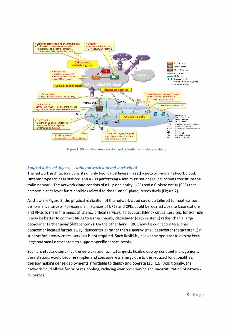
4. 5G mobile network architecture vision Figure 2 illustrates a 5G mobile network architecture that utilizes the enablers discussed previously. The
key elements in the architecture are summarized below.
� Two logical network layers, namely a radio network (RN) that provides only a minimum set of
L1/L2 functionalities and a network cloud that provides all higher layer functionalities.
� Dynamic deployment and scaling of functions in the network cloud through SDN and NFV.
� Lean protocol stack achieved through elimination of redundant functionalities and integration of
AS and NAS.
� Separate provisioning of coverage and capacity in the RN by use of C/U-plane split architecture
and different frequency bands for coverage and capacity.
� Relaying and nesting (connecting devices with limited resources non-transparently to the
network through one or more devices that have more resources) to support multiple devices,
group mobility and nomadic hotspots.
� Connectionless and contention-based access with new waveforms for asynchronous access of
massive number of MTC devices.
� Data-driven network intelligence to optimize network resource usage and planning.
9 | P a g e
Figure 2: 5G mobile network vision and potential technology enablers
Logical network layers – radio network and network cloud The network architecture consists of only two logical layers – a radio network and a network cloud.
Different types of base stations and RRUs performing a minimum set of L1/L2 functions constitute the
radio network. The network cloud consists of a U-plane entity (UPE) and a C-plane entity (CPE) that
perform higher layer functionalities related to the U- and C-plane, respectively (Figure 2).
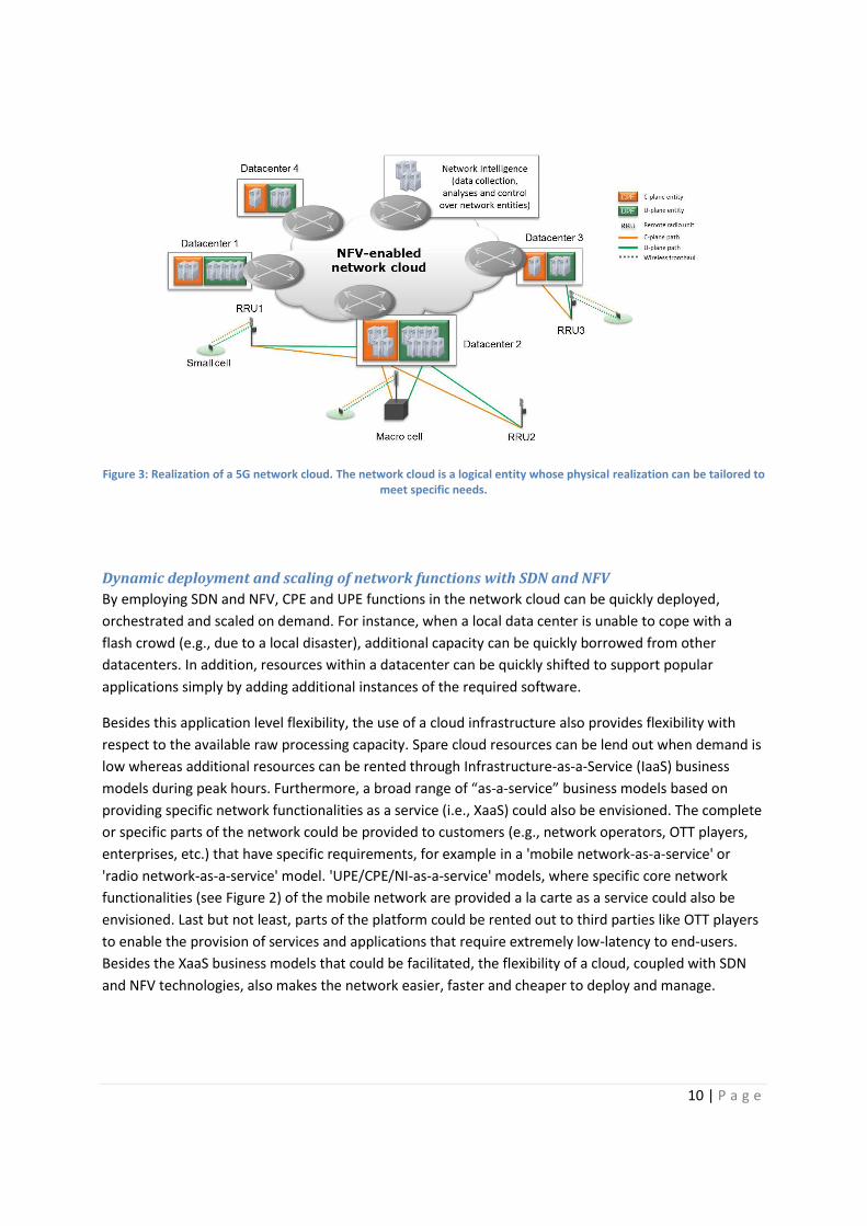
As shown in Figure 3, the physical realization of the network cloud could be tailored to meet various
performance targets. For example, instances of UPEs and CPEs could be located close to base stations
and RRUs to meet the needs of latency critical services. To support latency critical services, for example,
it may be better to connect RRU3 to a small nearby datacenter (data center 3) rather than a large
datacenter farther away (datacenter 2). On the other hand, RRU1 may be connected to a large
datacenter located farther away (datacenter 2) rather than a nearby small datacenter (datacenter 1) if
support for latency-critical services is not required. Such flexibility allows the operator to deploy both
large and small datacenters to support specific service needs.
Such architecture simplifies the network and facilitates quick, flexible deployment and management.
Base stations would become simpler and consume less energy due to the reduced functionalities,
thereby making dense deployments affordable to deploy and operate [15] [16]. Additionally, the
network cloud allows for resource pooling, reducing over provisioning and underutilization of network
resources.
10 | P a g e
Figure 3: Realization of a 5G network cloud. The network cloud is a logical entity whose physical realization can be tailored to meet specific needs.
Dynamic deployment and scaling of network functions with SDN and NFV By employing SDN and NFV, CPE and UPE functions in the network cloud can be quickly deployed,
orchestrated and scaled on demand. For instance, when a local data center is unable to cope with a
flash crowd (e.g., due to a local disaster), additional capacity can be quickly borrowed from other
datacenters. In addition, resources within a datacenter can be quickly shifted to support popular
applications simply by adding additional instances of the required software.
Besides this application level flexibility, the use of a cloud infrastructure also provides flexibility with
respect to the available raw processing capacity. Spare cloud resources can be lend out when demand is
low whereas additional resources can be rented through Infrastructure-as-a-Service (IaaS) business
models during peak hours. Furthermore, a broad range of “as-a-service” business models based on
providing specific network functionalities as a service (i.e., XaaS) could also be envisioned. The complete
or specific parts of the network could be provided to customers (e.g., network operators, OTT players,
enterprises, etc.) that have specific requirements, for example in a 'mobile network-as-a-service' or
'radio network-as-a-service' model. 'UPE/CPE/NI-as-a-service' models, where specific core network
functionalities (see Figure 2) of the mobile network are provided a la carte as a service could also be
envisioned. Last but not least, parts of the platform could be rented out to third parties like OTT players
to enable the provision of services and applications that require extremely low-latency to end-users.
Besides the XaaS business models that could be facilitated, the flexibility of a cloud, coupled with SDN
and NFV technologies, also makes the network easier, faster and cheaper to deploy and manage.

11 | P a g e
Lean protocol stack With virtualization, interfaces between network functionalities become interfaces between software.
Two separate protocols for the C-plane may no longer be relevant if both NAS and AS protocols can be
virtualized. Under a unified cloud paradigm, the NAS and AS protocols can be integrated into a single
protocol, removing redundant functionality. In current LTE, for example, the NAS ServiceRequest and
the RRC ConnectionRequest messages are concatenated but these could be merged into a single
message in a future cloud-based and virtualized network. Similarly, some procedures related to mobility
management, session management and security can be potentially removed. As an example, the
connection establishment procedure can be significantly simplified by requiring a hand shake only
between the peer entities of a single protocol. This will in turn realize faster connection establishment.
Bearer-based QoS management could also be replaced by simple IP marking, with proper mechanisms in
place to prevent all packets being marked with the highest QoS class.
Similarly for the U-plane, merging of functionalities in the RAN L2 and gateway functionalities in the
current core network (CN) can be considered. Virtualization of the U-plane is generally considered to be
more difficult than the C-plane, due to the sheer volume of data to be processed. Virtualization of the
RAN L2 protocols can demand significant processing power, as L2 protocols support various features
that are dynamic in nature, like dynamic transport block size (according to resource allocation and
instantaneous radio condition), segmentation and concatenation of packets, and hybrid ARQ. The radio
scheduler functionality and advanced features like mMIMO require accurate channel state information
(CSI) to be effective. Hence, if such features are to be virtualized, CSI also needs to be delivered to the
virtualized entity, potentially imposing significant transport overhead. However, with sufficient
advancements in technology and careful selection of functionalities, some of the services provided by L2
can be feasible for virtualization around 2020. This allows the functionalities provided by different RAN
and CN protocols to be merged and a single U-plane entity to provide radio transport services and
gateway functionalities, in principle. Nevertheless, careful study is needed to determine for which layers
such integration can occur.
One feature that can be potentially removed from the U-plane stack is ciphering, since this is
increasingly implemented by transport layer security (TLS) over IP. Generally, E2E solutions are more
efficient than encrypting segments along the path. However, E2E encryption implies no traffic visibility
along the path and makes traffic control in networks difficult. In many operator networks today,
intelligent mechanisms such as DPI and caching are used to optimize resource usage and improve QoE.
E2E encryption would make these intelligent mechanisms dysfunctional. As security of signals
transmitted over the air is essential, due to broadcast nature of radio signals, where to terminate
ciphering in the network is an important issue.
Independent provisioning of coverage and capacity with C/U-plane split architecture Coverage and capacity are provided independently in the RN with a C/U-plane split architecture. Macro
and metro base stations provide coverage using licensed spectrum in lower frequency bands and
existing cell sites, integrating, for example, NOMA and SIC to boost capacity [8].
12 | P a g e
Small cell base stations (e.g., Phantom cells [9]) and RRUs provide localized capacity using a combination
of licensed and unlicensed spectrum in low and high frequency bands. These cells are deployed indoors
and at outdoor hotspots. Advanced schemes (e.g., mMIMO) are also implemented in some RRUs and
small cells to boost capacity. Because of the highly variable user and traffic distribution in small cells,
they can be put to sleep or switched off completely when they are not needed to save energy.
Dynamically switching small cells on and off can provide significant energy savings without degrading
network performance [16].
Separating coverage from capacity enables independent mobility of C- and U-plane in areas with
overlapping coverage of macro and small cell base stations. In effect, the C- and U-plane for a terminal
can take different paths. This requires the terminal to support dual connectivity to multiple base
stations at the same time.
Relaying and nesting to support multiple devices, group mobility and nomadic hotspots Relays are used as a means to support group mobility (e.g., terminals in a moving vehicle) and nomadic
hotspots. In such scenarios, all transmissions within the group are aggregated at one or more entities
(e.g., a small cell) and relayed to the network through a wireless backhaul that connects to the network
cloud (Figure 2). Devices with limited resources, such as low-powered wearable devices, connect non-
transparently to the network through one or more devices that have more resources (nesting, Figure 2).
By connecting non-transparently, network paging procedures can be used to initiate connections to such
devices, thus reducing signaling traffic and power consumption. Together, relaying and nesting provides
support for a huge number of devices with diverse capabilities in a scalable and efficient manner.
Data-driven network intelligence The architecture allows the network cloud to collect various types of user-centric, network-centric and
context-centric data. The network cloud uses intelligent algorithms to provide real-time insights for
efficient resource management, mobility management, local offload decisions (e.g., network-controlled
D2D communications), QoE management, traffic routing and context-aware service provisioning (e.g.,
geocasting). Furthermore, the aggregated data can provide useful input for network planning. By
providing APIs to the network cloud, the collected data can be used in various forms for useful public
(e.g., urban planning) and commercial purposes. For example, the APIs can be used to facilitate new
businesses based on selling knowledge about network conditions as a service to OTT players, which can
allow them to provide a consistent service quality to end-users.
5. Issues Several issues need to be addressed in order to realize the proposed network architecture, in particular,
and 5G networks, in general. Some of these issues are summarized in Figure 4 and briefly discussed
below.
One issue that must be addressed is how legacy networks will interface and interoperate with the new
network architecture. One could imagine a migration step where the legacy CN and RAN are migrated to
separate cloud platforms during the development phase of 5G (Figure 4). In order to avoid building

13 | P a g e
parallel networks, it will be essential to specify interfaces and protocols between entities in the legacy
clouds and the new network cloud to ensure interoperability.
Figure 4: Overview of issues that must be addressed to realize 5G architecture vision
Another issue is to determine the optimal physical realization of the network cloud to meet
performance and cost targets. Whereas centralization of resources could result in savings from pooling,
it could also lead to performance bottlenecks, higher latency and single point of failure. Additional
robustness measures will also be needed to avoid devastating impact on service availability if the central
entity fails. Moreover, centralization could lead to the need for larger processing and transport capacity
at the central entity to process and transport the aggregated traffic, which could diminish cost savings
achieved by pooling. On the other hand, distributing resources could lead to performance
improvements and reduced latency, but could be costly due to reduced pooling gains and an increase in
the number of datacenter locations at corresponding higher operational expenses. Finding the right
balance will be an important issue.
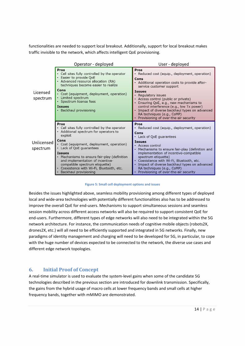
Ultra-dense small cell deployments will be especially useful for indoor and hotspot environments. As
shown in Figure 5, different deployment options have different implications for the network. In addition
to spectrum, backhaul is also an important issue, especially for user deployment. Local breakout may be
required for more efficient routing through the user-provisioned backhaul. However, this has
implications on the functionalities needed at the small cell base station. For instance, U-plane processing
14 | P a g e
functionalities are needed to support local breakout. Additionally, support for local breakout makes
traffic invisible to the network, which affects intelligent QoE provisioning.
Figure 5: Small cell deployment options and issues
Besides the issues highlighted above, seamless mobility provisioning among different types of deployed
local and wide-area technologies with potentially different functionalities also has to be addressed to
improve the overall QoE for end-users. Mechanisms to support simultaneous sessions and seamless
session mobility across different access networks will also be required to support consistent QoE for
end-users. Furthermore, different types of edge networks will also need to be integrated within the 5G
network architecture. For instance, the communication needs of cognitive mobile objects (robots2X,
drones2X, etc.) will all need to be efficiently supported and integrated in 5G networks. Finally, new
paradigms of identity management and charging will need to be developed for 5G, in particular, to cope
with the huge number of devices expected to be connected to the network, the diverse use cases and
different edge network topologies.
6. Initial Proof of Concept A real-time simulator is used to evaluate the system-level gains when some of the candidate 5G
technologies described in the previous section are introduced for downlink transmission. Specifically,
the gains from the hybrid usage of macro cells at lower frequency bands and small cells at higher
frequency bands, together with mMIMO are demonstrated.

15 | P a g e
Color code of users and the ground indicates achievable user data rate: Blue: 0 – 10 Mbps; Green: 10 – 100 Mb/s; Yellow: 100 – 500 Mb/s; Orange: 500 Mb/s – 1 Gb/s; Red: 1 Gb/s – 10 Gb/s; Pink: Over 10 Gb/s
Figure 6: Deployment environment of 5G real-time simulator
Figure 6 shows the deployment environment studied, which consists of buildings, moving vehicles, users,
macro base stations and a dense deployment of small cell base stations. A 7-cell model is assumed with
an inter-site distance of 500 m. Each macro cell has three sectors and each sector has 30 outdoor users
(i.e., penetration loss = 0 dB). A 3 km/h user speed is assumed. Ray tracing is applied using vertical plane
launch (VPL) method to emulate real propagation environment of a 750 m x 750 m dense urban area in
Shinjuku, Tokyo. The baseline system consists of LTE-based macro cells using 20 MHz bandwidth at 2
GHz. Each macro cell uses two transmit (Tx) antennas. An antenna gain of 14 dBi and a total transmit
power of 49 dBm are assumed for each macro cell base station. For evaluating the gains of network
densification and wideband transmission at higher frequency bands, 12 small cells are deployed per
sector. Each small cell uses 1 GHz bandwidth at 20 GHz. The number of Tx antennas per small cell is 64.
An antenna gain of 5 dBi and a total transmit power of 30 dBm are assumed for each small cell base
station. The number of receive antennas at the user terminal is 4 at both 2 GHz and 20 GHz.
For 2 x 4 MIMO transmission in macro cells, single user MIMO is applied based on implicit channel state
information (CSI) feedback using LTE Release 8 codebook. For 64 x 4 mMIMO transmission in small cells,
the CSI of users is assumed to be perfectly known at the small cell base station side and Hermitian
precoding is applied for multi-layer transmission. In order to improve both cell coverage (by
beamforming gain) and spectrum efficiency (by spatial multiplexing gain) of small cells, single user
MIMO and multi-user MIMO dynamic switching (up to 4 users) and rank adaptation (up to 4 layers/user)
Users
Macro cell w/ 3 sectors
Buildings
Moving vehicles
Small cells
Beams
16 | P a g e
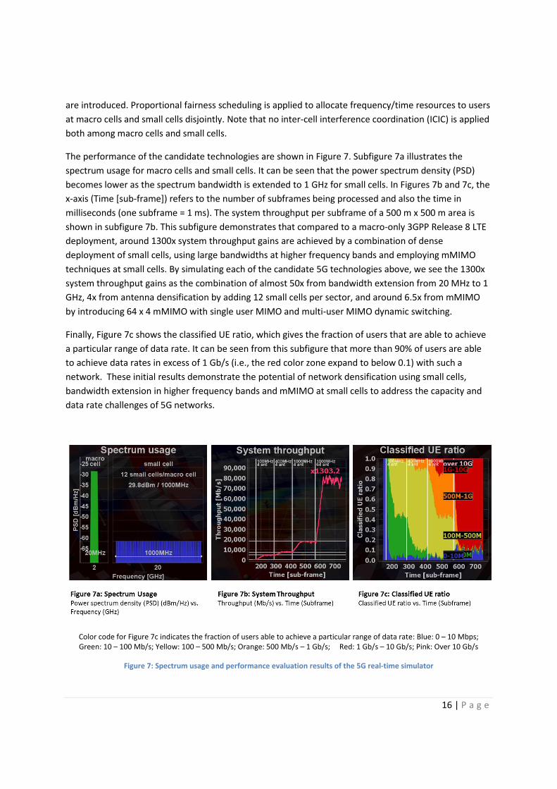
are introduced. Proportional fairness scheduling is applied to allocate frequency/time resources to users
at macro cells and small cells disjointly. Note that no inter-cell interference coordination (ICIC) is applied
both among macro cells and small cells.
The performance of the candidate technologies are shown in Figure 7. Subfigure 7a illustrates the
spectrum usage for macro cells and small cells. It can be seen that the power spectrum density (PSD)
becomes lower as the spectrum bandwidth is extended to 1 GHz for small cells. In Figures 7b and 7c, the
x-axis (Time [sub-frame]) refers to the number of subframes being processed and also the time in
milliseconds (one subframe = 1 ms). The system throughput per subframe of a 500 m x 500 m area is
shown in subfigure 7b. This subfigure demonstrates that compared to a macro-only 3GPP Release 8 LTE
deployment, around 1300x system throughput gains are achieved by a combination of dense
deployment of small cells, using large bandwidths at higher frequency bands and employing mMIMO
techniques at small cells. By simulating each of the candidate 5G technologies above, we see the 1300x
system throughput gains as the combination of almost 50x from bandwidth extension from 20 MHz to 1
GHz, 4x from antenna densification by adding 12 small cells per sector, and around 6.5x from mMIMO
by introducing 64 x 4 mMIMO with single user MIMO and multi-user MIMO dynamic switching.
Finally, Figure 7c shows the classified UE ratio, which gives the fraction of users that are able to achieve
a particular range of data rate. It can be seen from this subfigure that more than 90% of users are able
to achieve data rates in excess of 1 Gb/s (i.e., the red color zone expand to below 0.1) with such a
network. These initial results demonstrate the potential of network densification using small cells,
bandwidth extension in higher frequency bands and mMIMO at small cells to address the capacity and
data rate challenges of 5G networks.
Color code for Figure 7c indicates the fraction of users able to achieve a particular range of data rate: Blue: 0 – 10 Mbps; Green: 10 – 100 Mb/s; Yellow: 100 – 500 Mb/s; Orange: 500 Mb/s – 1 Gb/s; Red: 1 Gb/s – 10 Gb/s; Pink: Over 10 Gb/s
Figure 7: Spectrum usage and performance evaluation results of the 5G real-time simulator

17 | P a g e
7. Conclusions The important challenges that must be addressed by 5G networks were highlighted, namely, higher
capacity, higher data rate, lower E2E latency, massive device connectivity, reduced capital and
operations cost, and consistent QoE provisioning. A 5G architecture vision to address some of those
challenges was presented and a two-layer architecture was proposed, consisting of a radio network and
a network cloud. The proposed architecture integrates various enablers such as small cells, massive
MIMO, control/data(C/U)-plane split, NFV and SDN. The main concepts can be summarized as follows:
� Ultra-dense small cell deployments on licensed and unlicensed spectrum, under C/U-plane split
architecture, to address capacity and data rate challenges;
� NFV and SDN to provide flexible network deployment and operation, with integrated access
stratum (AS) and non-access stratum (NAS) features;
� Intelligent use of network data to facilitate optimal use of network resources for QoE
provisioning and planning.
Initial proof of concept investigations suggests more than 1000 times throughput gains compared to a
macro-only 3GPP Release 8 LTE deployment are achievable by a combination of dense deployment of
small cells, using large bandwidths at higher frequency bands and employing massive MIMO techniques
at small cells. Nevertheless, some of the components highlighted in the system concept have mutual
conflicts, when details are considered. Hence, how to balance the pros and cons of each aspect needs to
be carefully studied. Further investigations are necessary in particular: suitable techniques for use in
small cells in different frequency regimes; how to incorporate small cells with NFV and SDN in a cost
effective manner; and intelligent algorithms that better utilize the available network resources to
provide a consistent end-user QoE.
18 | P a g e
References
[1] Qualcomm, "The 1000x Mobile Data Challenge," in White Paper, Nov 2013.
[2] NSN, "Signaling is Growing 50% Faster than Data Traffic," in White Paper, 2012.
[3] METIS, "Scenarios, Requirements and KPIs for 5G Mobile and Wireless System (Deliverable D1.1),"
May 2013.
[4] "Advanced 5G Network Infrastructure for the Future Internet - Public Private Partnership in Horizon
2020," 2013.
[5] Y. Kishiyama, A. Benjebbour, T. Nakamura and H. Ishii, "Future Steps of LTE-A: Evolution Toward
Integration of Local Area and Wide Area Systems," IEEE Wireless Communications, vol. 20, no. 1, pp.
12-18, 2013.
[6] E. G. Larsson, F. Tufvesson, O. Edfors and T. L. Marzetta, "Massive MIMO for Next Generation
Wireless Systems," May 2013.
[7] S. Gollakota, S. Perli and D. Katabi, "Interference Alignment and Cancellation," in ACM SIGCOMM Computer Communication Review, 2009.
[8] A. Benjebbour, A. Li, Y. Saito, Y. Kishiyama, A. Harada and T. Nakamura, "System-level Performance
of Downlink NOMA for Future LTE Enhancements," in IEEE Globecom, 2013.
[9] H. Ishii, Y. Kishiyama and H. Takahashi, "A Novel Architecture for LTE-B: C-plane/U-plane Split and
Phantom Cell Concept," in Globecom Workshops (GC Wkshps), 2012.
[10] odor, ahlman, ildh, ar vall, eider, i l s and Tur nyi, esign spects of Network Assisted Device-to-Device Communications," IEEE Communications Magazine, vol. 50, no.
3, pp. 170-177, 2012.
[11] G. P. Fettweis, "A 5G Wireless Communications Vision," Microwave Journal, Dec 2012.
[12] B. Farhang-Boroujeny, "OFDM Versus Filter Bank Multicarrier," IEEE Signal Processing Magazine, vol. 28, no. 3, pp. 92-112, May 2011.
[13] EARTH Project Work Package 2, "Deliverable D2.1: Economic and Ecological Impact of ICT,"
https://www.ict-earth.eu/publications/deliverables/deliverables.html, 2011.
[14] "Network Functions Virtualisation - Introductory White Paper," in SDN and OpenFlow World Congress, Darmstadt, Germany, Oct 2012.
[15] EARTH Project Work Package 4, "Deliverable D4.3: Final Report on Green Radio Technologies,"
https://www.ict-earth.eu/publications/deliverables/deliverables.html, 2012.
[16] E. Ternon, P. Agyapong, L. Hu and A. Dekorsy, "Database-aided Energy Savings in Next Generation
Dual Connectivity Heterogeneous Networks," in WCNC, Istanbul, Apr 2014.
19 | P a g e
Biographies
Patrick Kwadwo Agyapong Patrick Agyapong is a researcher with the wireless research group at DOCOMO Communications
Laboratories Europe. His research focuses on designing incentive-compatible algorithms, protocols and
architectures to support next generation mobile communication needs, spanning the areas of resource
management, content distribution, network architecture and business strategy. He holds a PhD in
Engineering and Public Policy from Carnegie Mellon University, Pittsburgh, U.S.A. He also holds an MSc
in Electrical Engineering and a BSc in Electrical Engineering and Computer Science, both from Jacobs
University Bremen, Germany.
Mikio Iwamura Mikio Iwamura is a director of the wireless research group at DOCOMO Communications Laboratories Europe. He received his PhD and MSc degrees from King’s College London in 2006 and Science University of Tokyo in 1998, respectively. Before his current role, he was deeply engaged in LTE standardization, with over 300 contributions to 3GPP. He has over 100 patents internationally and has published over 20 technical journals and conference papers.
Dirk Staehle Dirk Staehle is a manager at DOCOMO Communications Laboratories Europe. He is responsible for the standardization team contributing to 3GPP SA2 and ETSI NFV standardization groups. He received his PhD from the University of Würzburg in 2004 and continued as Assistant Professor leading the wireless network research group before joining DOCOMO in 2011. His research activities include network function virtualization, machine type communication, application and QoE aware traffic and resource management, and radio network planning.
Wolfgang Kiess Wolfgang Kiess studied at the universities of Mannheim and Nice/France and holds a diploma in business information systems from the University of Mannheim and a PhD in computer science from the University of Düsseldorf. He is the leader of the virtualization research team at DOCOMO Communications Laboratories Europe, focusing on cellular core network virtualization, cloud computing, and 5G.
Anass Benjebbour Anass Benjebbour obtained his PhD and MSc in Telecommunications in 2004 and 2001, respectively, and his Diploma in Electrical Engineering in 1999, all from Kyoto University, Japan. He is currently an assistant manager of the 5G team within NTT DOCOMO, INC. He served as 3GPP RAN1 standardization delegate during LTE Release 11, as secretary of the IEICE RCS conference, and editor for the IEICE
Communications Magazine. He is senior member of IEEE and IEICE.