kentech instruments ltd. low magnification … lightstar3 controller (en 01/01), ... figure 16...
TRANSCRIPT

Kentech Instruments Ltd.,
Unit 9, Hall Farm Workshops, South Moreton, Didcot, Oxon, OX11 9AG, U.K.
Tel: 01235 510 748 Fax: 01235 510 722
International tel: (44) 1235 510 748 International fax: (44)1235 510 722
E-mail [email protected]
Kentech Instruments Ltd.
LOW MAGNIFICATION
X–RAY
STREAK CAMERA
with Intensifier [Photek 40mm single MCP]
and CCD camera [FlamestarIII from LaVision]
20th. January 2001
Serial Number J00*****
PLEASE READ THIS MANUAL CAREFULLY BEFORE USING THE
CAMERA.

2
Kentech Instruments Ltd., Unit 9, Hall Farm Workshops, South Moreton, Didcot, Oxon, OX11 9AG, England.
20th. January 2001
SERIAL NUMBERS
J00*****/3 Streak tube
J00*****/2 Streak tube standard electronics
J00*****/1 Streak Tube Fast sweep electronics
22000511 (Photek ref. 00215) Photek intensifierE00008 Photek intensifier power supply22/23-01/01-5451 Lightstar3 camera head, LaVision22/23-01/01-5451 Lightstar3 controller (EN 01/01), LaVisionLVMN:0900-013 PCI A to D convertor, Theta SystemsPCI-D1024H PCI TTl I/O card, with piggy back card.
DISCLAIMER
This equipment contains high voltage power supplies. Although the current supply capacity is
small, careless use could result in electric shock. It is assumed that this highly specialised equipment
will only be used by qualified personnel.
Kentech Instruments Ltd. accept no responsibility for any electric shock or injury arising from
use or misuse of this equipment. It is the responsibility of the user to exercise care and common sense
with this highly versatile equipment.

3
Kentech Instruments Ltd., Unit 9, Hall Farm Workshops, South Moreton, Didcot, Oxon, OX11 9AG, England.
20th. January 2001
Figure Caption
Figure 1 Preset potentiometers are accessed after removal of the right hand cover 8Figure 2 The zoom electrode and the position of the drilled screws 8Figure 3 The standard sweep unit and focusing supply 8Figure 4 The rear panel standard sweep unit and focusing supply
showing the sweep outputs and HT interlock 10Figure 5 The Streak tube output face and intensifier mounting flange 10Figure 7 The standard sweep unit and focusing supply 16Figure 6 The fast sweep unit 16Figure 8 The CCD Camera head with intensifier fitted. 18Figure 9 The rear of the CCD head, showing the gain and offset controls 20Figure 10 The rear of the CCD head, showing the leads fitted. 20Figure 11 The CCD head, showing the air flow ports 21Figure 12 The PCI cards installed showing the trigger lead. 22Figure 13 The rear of the computer with camera leads attached and detached. 22Figure 14 The parallel port Dongle fitted. 23Figure 15 The rear of the CCD camera power supply 23Figure 16 Acquisition Timing window 26Figure 17 Gain and Offset adjustment at the computer PCI card 29Figure 18 A typical screen and Window set. 28Figure 19 The insides of the CCD head 30Figure 20 Timing diagram showing the trigger input and sweep speed 6 34Figure 21 The monitor output into 50Ω 34Figure 22 Connections, internal 35Figure 23 Connections, external 36Figure 24 Focusing supply, block diagram 37Figure 25 Focus Unit 38Figure 26 EHT control board components 39Figure 27 EHT board EHT tracks top 40Figure 28 EHT board EHT tracks bottom 41Figure 29 Divider network 42Figure 30 Sweep power supply circuit 43Figure 31 Sweep power supply components 44Figure 32 Sweep power supply tracks 45Figure 33 Sweep unit, block diagram 46Figure 34 Sweep unit Trigger board (KT101) 47Figure 35 Sweep unit timing switch (KT106/modified rates) 48Figure 36 Cathode/mesh assembly 49Figure 37 Low Density cathode manufacture 50Figure 38 The Polaroid film back can be fitted to the intensifier. 51Figure 39 Photek Intensifier 52Figure 40 Linear calibration lineouts 53Figure 41 Horizontal calibration 54Figure 42 Vertical calibration 54Figure 43 Horizontal static resolution estimate 55Figure 44 Vertical static resolution estimate 56Figure 45 Static deflection sensitivity measurement 57Figure 46 Static deflection sensitivity results 58Figure 47 Sweep speed 1 measurement 59Figure 48 Sweep speed 2 measurement 59Figure 49 Sweep speed 3 measurement 60Figure 50 Sweep speed 4 measurement 60Figure 51 Sweep speed 5 measurement 61Figure 52 Sweep speed 6 measurement 61Figure 53 The two fast ramps superimposed showing the rise time 62Figure 54 The two ramps superimposed showing the long time history. 62Figure 55 The CCD camera head attached to the streak camera 63Figure 56 Computer station 64Figure 57 The A to D convertor PCI card 65Figure 58 The internal trigger lead to the A to D convertor 66Figure 59 The Intensifier cable gland. 67Figure 60 Intensifier power supply 68Figure 61 Intensifier lead pin out 69Figure 62 Engineering drawing for cathode with normal slit and low angle of incidence option 70Figure 63 Engineering drawing for cathode with narrow slit and low angle of incidence option 71Figure 64 Engineering drawing for re-entrant housing 72

4
Kentech Instruments Ltd., Unit 9, Hall Farm Workshops, South Moreton, Didcot, Oxon, OX11 9AG, England.
20th. January 2001

5
Kentech Instruments Ltd., Unit 9, Hall Farm Workshops, South Moreton, Didcot, Oxon, OX11 9AG, England.
20th. January 2001
Contents
DISCLAIMER 2
Serial Numbers 2
1 INTRODUCTION 61.1 SPECIFICATIONS OF THE STREAK CAMERA 6
2 GETTING TO KNOW THE INSTRUMENT 62.1 LAYOUT AND PRINCIPLES OF OPERATION 62.2 THE ELECTRON OPTIC FOCUSING 72.3 SWEEP CIRCUITS 72.3.1 THE STANDARD SWEEP UNIT 72.3.2 THE FAST SWEEP UNIT 72.4 MAGNETIC FIELDS 82.5 MECHANICS 8
3 USE 93.1 CONNECTIONS AND MECHANICS 93.2 CATHODE AND MESH ASSEMBLY 113.3 INITIAL POWER-UP 123.4 PROCEDURE FOR TIMING THE STREAK CAMERA. 133.5 TESTS 133.6 POSSIBLE FAULTS. 15
4 CIRCUIT DESCRIPTIONS 164.1 SWEEP CIRCUITS 164.1.1 STANDARD SWEEP UNIT OPERATE, SYNCH AND FOCUS 174.1.2 FAST SWEEP UNIT OPERATE, SYNCH AND FOCUS 174.2 THE FOCUSING SUPPLY 17
5 CATHODES 185.1 CATHODE MANUFACTURE 18
6 PHOTEK IMAGE INTENSIFIER AND LAVISION CCD CAMERA 186.1 INTERFACING THE INTENSIFIER TO THE STREAK CAMERA 186.2 INTENSIFIER POWER SUPPLY AND TRIGGERING 216.3 CCD READOUT SYSTEM 226.3.1 A SUITABLE COMPUTER 226.3.2 SETTING UP THE COMPUTER 246.3.3 SOFTWARE INSTALLATION 246.3.4 FIRST RUN OF THE SOFTWARE 246.4 CCD TIMING AND TRIGGERING 256.5 ADJUSTING THE GAIN AND OFFSET 286.6 CONTINUOUS ILLUMINATION 296.7 TEMPERATURE CONTROL 29
7 SWITCHING BETWEEN FILM BACK AND CCD READOUT HEAD 307.1 FITTING THE FILM BACK 307.2 REFITTING THE CCD BACK TO THE INTENSIFIER 317.3 USING THE INTENSIFIER WITH FILM 32
8 DATA SHEETS 328.1 STATIC FOCUSING 328.2 SWEEP CIRCUITS 338.3 TRIGGER DELAYS 338.4 BIAS VOLTAGES 33
9 SYSTEM EQUIPMENT LIST 73
6
Kentech Instruments Ltd., Unit 9, Hall Farm Workshops, South Moreton, Didcot, Oxon, OX11 9AG, England.
20th. January 2001
1 INTRODUCTION
This manual describes the operation and use of the Kentech Low Magnification X–ray streak
camera. This camera is optimised for the ultra sensitive recording of X–ray images and spectra from
laser produced plasmas. The (approximately X1.2) magnification allows a 25mm length cathode to
be used within a 40mm diameter intensifier window. The manual gives the mechanical and electrical
specifications and describes the setting up procedure to obtain optimum time resolved data.
This manual describes the components made by Kentech in some detail and gives enough
information of the parts of the system supplied by others to Kentech to allow the user to obtain data.
For more information on the intensifier, the CCD camera and the software the user should consult
the relevant manuals included with the system. Please contact Kentech regarding any problems or
uncertainties. A more prompt response to software issues will probably be available through
LaVision directly but Kentech will endeavour to sort any such issues should they be presented to us.
1.1 SPECIFICATIONS OF THE STREAK CAMERA
Trigger delay standard sweep unit ~30ns on the fastest setting, see timing graphs
Trigger delay fast sweep unit 16ns
Electro-optical magnification X 1.2 (nominal)
Number of sweep speeds six on the standard unit + one on the fast unit
Phosphor P20
Cathode length >25mm
Supply Universal
Sweep Trigger input Normally 10 volts, rising in
1ns for minimum delay
Trigger input to the intensifier may be triggered from the standard sweep unit.
Spatial resolution Better than 100 µm at the cathode
Sweep hold off time standard sweep unit approximately 50µs
Fast sweep unit ~ 3ns!!
2 GETTING TO KNOW THE INSTRUMENT
The camera system comprises the camera tube and two boxes of electronics. In addition there
is an intensifier with a third box of electronics and a readout system. The readout system comprises,
the camera head with fibre optic taper ready mounted onto the intensifier, a power supply with
thermoelectric cooler, a pair of PCI boards for a computer and software on both CD rom and Floppy
disk (for customer settings).
The streak camera electronics are remote from the electron optics, which are of a design unique
to Kentech, allowing compact mechanics. The electron optics have been designed to use only three
focusing potentials. The outer diameter of the re-entrant housing is only 145mm. The re-entrant
design allows the photocathode to be very close to the plasma.
2.1 LAYOUT AND PRINCIPLES OF OPERATION
The tube fits into the re-entrant vessel the outside diameter of which is 145mm. The vacuum seal
is made to the outside wall of the interaction chamber. Figures 22 and 23 show the internal parts and
connections to the camera.
The X–rays, which are incident on the photocathode, produce photoelectrons. The photoelectrons
are imaged by the focusing electrodes, passing through the hole in the anode and form an image on
the phosphor at the end of the streak tube. With a slit in front of the photocathode an image of the

7
Kentech Instruments Ltd., Unit 9, Hall Farm Workshops, South Moreton, Didcot, Oxon, OX11 9AG, England.
20th. January 2001
slit is formed on the phosphor. This image is swept across the phosphor by a ramp potential applied
to deflection plates situated just beyond the anode hole. Position along the photocathode is magnified
nominally by a factor of 1.2 onto the phosphor. The direction normal to this corresponds to time.
There is an inversion in the electron optics.
2.2 THE ELECTRON OPTIC FOCUSING
Before the high voltage focusing supply is switched on the vacuum chamber must be at a suitably
low pressure. For low time resolution work the extraction field between the cathode and extraction
grid can be 15kVcm-1 and in this case the pressure should be below 10-4 torr in the region of the
cathode. In order to obtain higher time resolution it will become necessary to increase the extraction
field to >30kVcm-1 and under these conditions we recommend that the pressure be below 10-5 torr,
see section 3.2. At higher pressures electrical breakdown may occur which can damage the cathode,
mesh and even the intensifier.
A block diagram of the focusing supply is shown in figure 24. The approximate voltages applied
to the focusing electrodes are:
Photocathode -15.0kV
Mesh -13.7kV (adjustable)
Cone -14.0kV (adjustable)
The focusing power supply is set to produce these voltages during the factory test of the camera,
(see data section 8).
The voltages are produced by a resistive divider as illustrated in figure 29. This unit is potted.
The two adjustable potentials can be set through holes in the bottom of the unit.
GREAT CARE MUST BE USED WHEN FOCUSING. USE AN INSULATED
SCREWDRIVER.
Figure 22 diagrammatically shows the cathode assembly. Note the high value resistor situated
close to the mesh. This limits the current flow in the event of breakdown and can save the mesh/
cathode from destruction. The capacitance of the cathode to mesh is sufficient to supply the charge
required to form an image. In any case the inductance of the leads effectively isolates the electrodes
from the supply.
2.3 SWEEP CIRCUITS
2.3.1 THE STANDARD SWEEP UNIT
The streak voltage is supplied by an external ramp generator. Figure 33 shows a block diagram
of the unit.
The standard ramp generator consists of an avalanche unit. It delivers ramp voltages of about
2500 volts rising in 500ps on the fastest range. By having a large voltage the nonlinearity of the ramp
is stretched by over scanning the phosphor. In addition there is a “SYNCH/OPERATE” switch. This
sets the start position to either at screen edge to off screen. The positions may be adjusted with four
potentiometers accessible by removing the right side of the unit, see figure 1. Use a high voltage 1
GΩ probe and DMM on the ramp outputs whilst adjusting these voltages.
2.3.2 THE FAST SWEEP UNIT
The fast sweep unit is for use in fast short lived experiments where maximum time resolution
is required.

8
Kentech Instruments Ltd., Unit 9, Hall Farm Workshops, South Moreton, Didcot, Oxon, OX11 9AG, England.
20th. January 2001
It consists of an avalanche pulse generator the output of which is split, one output is inverted and
then each dives one of the sweep plates on the streak tube. This takes the place of the sweep unit within
the standard sweep and focusing supply. There is no focusing supply in the fast sweep unit and that
in the standard unit must be used.
The output waveforms are show in figure 53 and the long time history in figure 54. Note that they
are relatively short lived. The sweep hold off time is just a few ns, compares to 50 µs with the standard
unit. It is very important that the user times up the experiment on the rising edge of the ramps not the
falling edge. They are easily distinguished by delaying the trigger signal by a few tens of ps. If timed
on the correct edge the image will move to the left (towards the negative ramp supply). If the image
moves the wrong way or not much at all then one is timed up on the wrong edge and the timing is
a ns or so out.
The bias voltage controls for the fast sweep unit are located on the rear panel.
2.4 MAGNETIC FIELDS
The electron optics are prone to image displacement under the influence of stray magnetic fields.
To remove this effect a mumetal screen, which fits around the re-entrant housing, is supplied. It is
not essential to use this screen, however, it is recommended if any magnets are around the chamber
(such as ion pumps or gauges).
NOTE
The use of screws of magnetic materials in or near the photocathode assembly can give rise to
image displacement. If it is necessary to replace screws ensure that they are of unplated brass or
nonmagnetic stainless steel. The use of nickel (magnetic) plated brass screws has not been found to
cause problems but we would advise against it. Similarly the residual magnetic field from stainless
steel screws generated in the screw manufacturing process has not been found to be a problem.
The screws clamping the snout should be nylon.
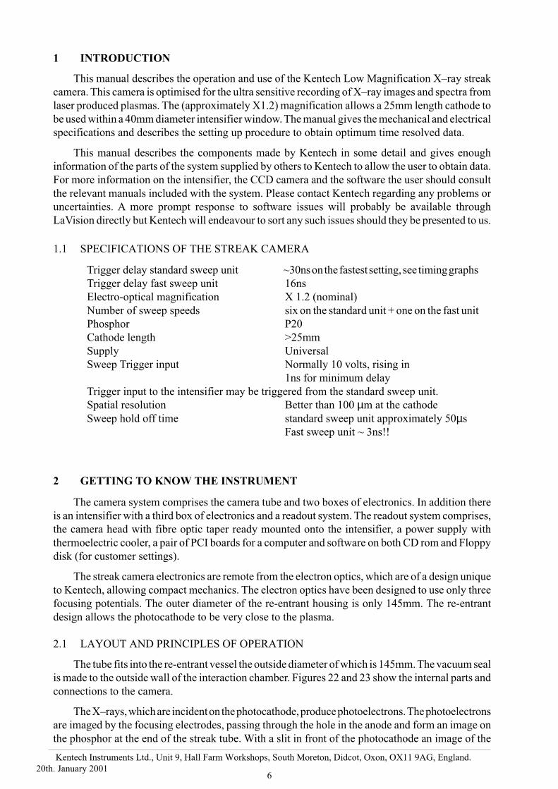
2.5 MECHANICS
Note that the nine screws clamping the inner housing cover with the three crescent shaped
clamps are drilled to permit evacuation of the blind holes. Do not mix these screws with others of
similar size used elsewhere on the instrument. (A few spares are provided.)
Figure 1 Preset potentiometers are accessed after removal of the right hand cover
9
Kentech Instruments Ltd., Unit 9, Hall Farm Workshops, South Moreton, Didcot, Oxon, OX11 9AG, England.
20th. January 2001
3 USE
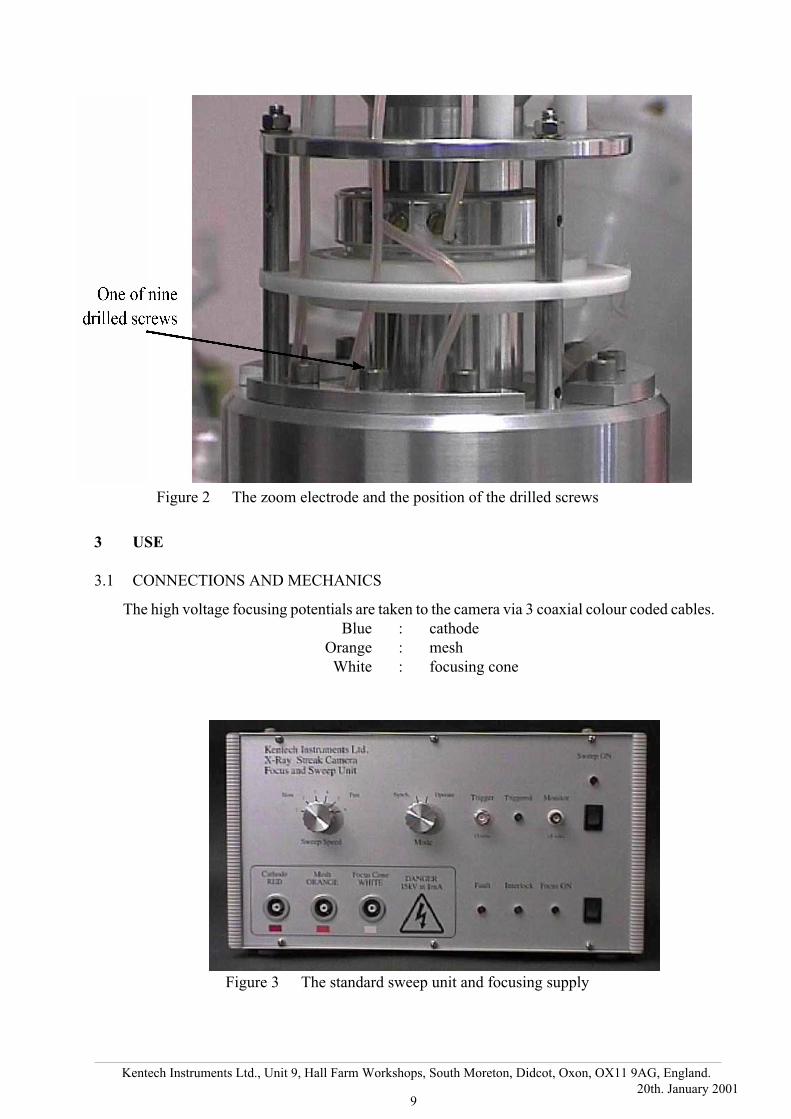
3.1 CONNECTIONS AND MECHANICS
The high voltage focusing potentials are taken to the camera via 3 coaxial colour coded cables.
Blue : cathode
Orange : mesh
White : focusing cone
Figure 2 The zoom electrode and the position of the drilled screws
Figure 3 The standard sweep unit and focusing supply

10
Kentech Instruments Ltd., Unit 9, Hall Farm Workshops, South Moreton, Didcot, Oxon, OX11 9AG, England.
20th. January 2001
The standard sweep unit, which is combined with the focusing unit, is connected via two 50Ωleads. These leads have “N” type connectors that fit the sweep unit and "N" connectors to fit the
camera. The camera is labelled with the appropriate ramp connections, as is the sweep unit. These
‘N’ type connectors may break down if used unmated. Avoid unmated use and always keep them
clean and free from metal particulates. If necessary regrease the threads to reduce thread wear which
leads to brass particles in the connectors.
Remember that metal particulates can cause a break down in the connectors and an also get
embedded in the soft fibre optics used on the camera.
Figure 22 shows the internal connections and figure 23 shows the sense of the connectors on the
camera face. The direction of increasing time is also shown in this figure, time goes from the negative
ramp side towards the positive. This direction with respect to the camera housing may be reversed
by swapping the polarity of the sweep leads. Do not forget that there is a further inversion in a lens
coupled readout system but that this is normally accounted for in the readout head. Flat field
intensifiers and fibre optically coupled CCD cameras, as supplied with this system, do not invert the
image, but intensifiers with crossover electrostatic lenses do.
CCD cameras may invert the image depending upon how they are configured. The unit supplied
with system does do this in hardware but the effect is reversed in the supplied software.
The re-entrant design allows complete access to the internal components of the camera without
disturbing the re-entrant vessel. Since this vessel is the usual mounting point for any diagnostic
attachment, removal of the camera streak tube will not disturb the alignment. To remove the streak
tube any intensifier that is fitted should be removed. The chamber should be vented at the last moment
as this will improve the pump down time. There are eight holes in the camera on the intensifier
mounting flange.
An Allen key (supplied) can be passed through these holes to remove the eight screws which hold
the streak tube to the re-entrant housing. The streak tube must be withdrawn carefully so that the
cathode assembly does not strike the re-entrant housing.
The time for which the camera is exposed to the atmosphere should be minimised as;
(i) the cathode may degrade under the influence of atmospheric moisture and (ii) the pump down
time is shorter for a short exposure to air.
Figure 4 The rear panel standard sweep unit and focusing supplyshowing the sweep outputs and HT interlock

11
Kentech Instruments Ltd., Unit 9, Hall Farm Workshops, South Moreton, Didcot, Oxon, OX11 9AG, England.
20th. January 2001
N.B. The mechanical versatility allows the camera to be oriented in many ways. Be sure that the
slit axis is correctly aligned with respect to any diagnostic attachments.
3.2 CATHODE AND MESH ASSEMBLY
For transit the cathodes and meshes are stored in a protective container. They should be
transferred to a more suitable container on receipt, for example an evacuated desiccator. Consequently
these need to be inserted before the camera can be used. The instructions that follow refer to
components shown in figure 36. In order to access the photocathode assembly four nylon screws
around the periphery of the holder should be removed. The end may then be removed. Always take
extreme care at this stage. The photocathodes are delicate and subject to contamination. The meshes
(underneath) are also very fragile and expensive. With the mesh and photocathode removed there is
a direct line to the output phosphor (although there is only a small aperture in the lens assembly).
Hence particular care must be taken not to drop small screws or other items into the camera.
The items to be placed into the snout of the camera are as follows and must be in the sequence
and orientation specified.
1 Mesh contact ring (not actually removable without unsoldering from lead) solder
contact side downwards. The contact ring must seat evenly with solder of the
connection being in the rebate of the housing.
2 Mesh with mesh side upwards.
3 Spacer. There are two standard spacers. Normally the 3mm one should be used. The
1.5mm one is used to obtain greater time resolution but a better vacuum may be
required to prevent breakdown. If the vacuum and cathode quality permit, a 1.5mm
spacer may be used. The voltage across this gap is about 4.5kV giving extraction
fields from 15 to 30 kVcm-1.
The spacer may be reduced even further. We have worked with and 1mm spacers (not
Figure 5 The Streak tube output face and intensifier mounting flange

12
Kentech Instruments Ltd., Unit 9, Hall Farm Workshops, South Moreton, Didcot, Oxon, OX11 9AG, England.
20th. January 2001
supplied here) on low magnification cameras but only after gaining confidence at
larger spacings and establishing a good vacuum. Make sure that when using very
high extraction fields that the condition of both the mesh and cathode is good and that
there are no spikes protruding. In addition the spacers and snout must be very
clean and free from contamination or burn marks. If burn marks occur they must
be removed completely. This usually involves machining the damage away or
replacement. Solvent cleaning does not work well enough.
This system has been supplied with a selection of thick spacers to permit the use of the reflection
cathode.
4 Photocathode with photocathode side downwards i.e. nearest the mesh.
5 Slit, providing that the cathode is not made on a slit substrate.
6 Photocathode contact ring with solder connection upwards away from the
photocathode.
7 Remaining spacer(s). Must be placed in so that the rebate covers the solder
connection to the photocathode contact ring. If reduced thickness spacers have been
used between the mesh and cathode more spacers may be necessary here to give
enough height to the stack of components so that they are compressed by the outer
clamping piece.
When using the low angle of incidence option it will be necessary to use a top spacer
with a cut out. Several are supplied.
Note 1:-Cathodes come in two main formats, normally for slow sweep speeds the cathode and
slit are separate items. In this case the slit should go in after the cathode. For faster work we have made
the cathode on the slit assembly. This eliminates two main problems, firstly if a laser beam is focused
onto the slit the beam may well have expanded again by the time it reaches the cathode. Secondly,
multiple reflections between the cathode and slit may give rise to spurious results. By using a single
slit/cathode unit these are overcome, however, at the expense of losing independent control of the
slit and cathode.
Note 2:- This system has been modified for both reflection and low angle illumination of the
cathode. Suitable cathodes are supplied.
Note 3:- The slits provided are not suitable for low angle of incidence or reflection work and the
user must provide their own method to ensure the image on the cathode is narrow so that time
resolution is available.
3.3 INITIAL POWER-UP
It is necessary for the vacuum interlock to be set before the HT can be turned on. This requires
that the vacuum interlock connector at the rear of the unit be shorted out. It is intended that this be
connected to relay contacts on a vacuum gauge. The focusing supply must not be turned on if the
pressure is higher than 10-4 torr. At extraction fields greater than ~15kVcm-1 (3 mm spacer) it may
be necessary to obtain a better pressure. We recommend that the camera first be timed and set up with
a low extraction field (3mm spacer between the cathode and mesh). Once the system is operating
satisfactorily at this field the spacer can be reduced and the vacuum improved.
When the power is first applied a small breakdown will usually occur as a result of absorbed gas
released under the influence of high electric fields. Normal procedure, after the vacuum chamber has
been evacuated, is to turn the camera on with the intensifier removed while watching the phosphor

13
Kentech Instruments Ltd., Unit 9, Hall Farm Workshops, South Moreton, Didcot, Oxon, OX11 9AG, England.
20th. January 2001
in semidarkness. At the first application of power there will probably be a slight flash of light. The
focusing supply should be switched on and off a few times, such that no light is visible on the
phosphor and the fault does light not flash. It may be necessary to wait for the pressure to improve
before this test is passed. Only after this test is passed satisfactorily should the intensifier be mated
and powered up. This test is only required once after venting the vacuum chamber.
It is not a good idea to leave the camera powered up for long periods while waiting for shots as
an unexpected rise in the chamber pressure due to accidental venting or possibly pump failure could
result in destruction of the cathode and/or the mesh.
It is also undesirable to leave recording film, if used, exposed to the intensifier for any longer
than is necessary as it may pick up noise and degrade the data.
For use with the CCD readout system supplied please see section 6
3.4 PROCEDURE FOR TIMING THE STREAK CAMERA.
In general the trigger signal should be timed so that it coincides with the X–ray signal on the
photocathode, with allowance made for:
(i) the flight time of electrons from the cathode to the sweep plates (approximately
1.7ns)
(ii) the time delay from triggering the sweep unit to the image reaching the middle of
the screen. This time depends very much on the sweep speed in use.
(iii) the flight time of photons from the plasma to the cathode
(iv) the relative timing of the electrical trigger and the arrival of the laser pulse at the
target
Alternatively timing can be performed in the usual manner, i.e. time up in a "SYNCH" mode
and then switch to the “OPERATE” mode.
In a "SYNCH" mode the image starts at on screen at the edge. If the image does not sweep, i.e.
it remains in the static untriggered position, then the trigger arrived after the event and the trigger
delay must be reduced. Alternatively, if no image is seen on the screen then the trigger arrived too
early and the image was swept off screen before the event. In this case the trigger delay should be
increased. With this procedure a binary search for the event can be made, but beware of bad shots
or other mishaps that can lead one down a false trail in the binary search. Go back and check old
positions occasionally as not seeing the image can be caused by a lack of intensifier trigger or no
focus voltage, also a stationary image can be caused by a loss of sweep signal.
Once a moved image is recorded the timing should be adjusted so that the image is just on the
far side of the phosphor (away from the start point) and then the unit can be switched to “OPERATE”.
The swept beam spends a significant amount of time off screen before arriving at the screen it may
be necessary to trigger a little earlier to see the image on screen in “OPERATE” mode. See the timing
diagrams in figures 47 to 54.
3.5 TESTS
The electron optics may be tested with either a DC X–ray source or a DC UV source, such as
a mercury vapour lamp with quartz envelope. However, for optimum focus, the wavelength should
match that to be used in the experiment. A suitable test pattern may be needed. We can supply
cathodes made onto grids to do this. [Dynamic focusing effects may occur at high sweep speeds. In
this case it will be necessary to refocus the camera slightly at the sweep speed in use.]

14
Kentech Instruments Ltd., Unit 9, Hall Farm Workshops, South Moreton, Didcot, Oxon, OX11 9AG, England.
20th. January 2001
The camera must be operated in a vacuum so the user must provide a suitable pumping system.
The vacuum requirement is a pressure of not more than 10-4 torr. A suitable window and cathode must
be provided for UV use. (Kentech can advise on the supply of such a cathode, being either 10nm gold
or 100nm aluminium on a quartz substrate) and a UV mercury vapour lamp, which will operate in
the vacuum chamber. Alternatively a more powerful lamp may be imaged through a quartz window
onto the cathode.
A typical mercury vapour lamp operating 20cm from the cathode will give a bright image on an
intensifier in contact with the phosphor. With suitable cathodes and reduced lamp to cathode spacing,
it is possible to obtain moderately bright images without an intensifier. Remember that the cathode
is at 15kV and that the lamp is probably grounded. In normal (swept or short exposure) operation an
intensifier should always be used in order to maintain a low electron current in the tube and still obtain
a recordable image. It is possible to melt the cathode with some types of UV lamp. Also the UV output
from UV lamps usually increases significantly as they warm up.
The focus controls may be accessed through the bottom cover of the focusing supply. Great care
must be exercised when this is done as high voltages are present. The focusing potentiometers may
be adjusted by turning the potentiometers in the potted EHT divider network. The screwdriver used
MUST be insulated. It is possible for the sweep plates, if left unconnected, to become charged causing
image displacement and also for them to pick up electrical noise. Consequently we recommend that
they be grounded during static focusing work.
With the DC source, the focusing supply and the intensifier, switched on, the focus should be
set for optimum image quality. The two potentials are interdependent and the optimum image quality
is obtained by iterating between the two settings. The cathode voltage should first be set to 15kV.
Then a best image should be found by adjusting the mesh potential and then the focus voltage should
be changed slightly. The mesh voltage should be again set for a best image and the image compared
with that obtained with the previous focus setting. The greatest effect of the focus voltage will be on
those parts of the image furthest from the axis. The focus should be chosen to give the best edge image
quality while always maintaining the mesh potential at a best image position. The position of the
crossover should also be close to the hole in the anode. If it is not vignetting will occur. This is obvious
when focusing the camera. Note that vignetting can occur if the crossover is either too far or too near
the anode. A suitable mid position must be found. This will ensure that the cross over is in the sweep
plate assembly.
If DC tests are performed with a CCD readout system it is important that the exposure is
maintained at a constant time for image comparison. It may be advisable to trigger the intensifier also.
The intensifier is gated for ~300µs when gated, several gate pulses can be used to obtain a brighter
image.
Stray magnetic fields may displace the image slightly. The mumetal screen may be adequate to
remove this if necessary. Otherwise the magnetic field will have to be eliminated.

15
Kentech Instruments Ltd., Unit 9, Hall Farm Workshops, South Moreton, Didcot, Oxon, OX11 9AG, England.
20th. January 2001
3.6 POSSIBLE FAULTS.
1 No DC image
Focusing unit not on or vacuum interlock not set.
Insensitive cathode.
Bad connections to cathode/mesh assembly.
Short circuit between mesh and cathode.
Breakdown of EHT feed (indicated by fault light on focusing supply).
2 Bad focus.
Poor connections to cathode/mesh.
Old/damaged cathode.
Poorly mated EHT connector.
Fault in bias/sweep supply. (Confirm by switching off sweep circuit supply, which should
restore focus).
Focus voltages have drifted (unlikely).
Photocathode and mesh not normal to camera axis.
Image is due to x-rays going straight through the tube and exciting the phosphor. Check that
no image is present with the focusing unit switched off. If necessary block the direct x-ray path.
.
3 No streaked image.
Intensifier triggering at wrong time from noise.
CCD camera triggering at the wrong time.
Sweep unit triggering at wrong time from noise.
Sweep feeds incorrectly connected.
Inadequate trigger signal causing jitter.
4 Spurious blobs of light.
Breakdown in chamber.
Pressure too high. Check vacuum and perform initial power up test.
Breakdown on shot. Plasma or target debris getting into electron optics. Is front of re-entrant
vessel adequately screened? It is wise to restrict the front aperture as much as possible and
cover the X–ray line of sight with as thick a filter as will transmit the desired X–rays.
5 Reduced sweep speed combined with loss of focus
Bad connection of one sweep lead. This reduces applied voltage ramp but also fails to a
maintain zero potential in drift tube, hence affecting the focus.
6 Jitter present in image.
Inadequate or irreproducible trigger signal. The electronics has a jitter of about 20ps rms. It
is necessary to provide a good and stable trigger source for the electronics. This may well not
be easy but is left to the user. Kentech can advise about solution to trigger problems but the
subject is too wide for a discussion here.
N.B. Poor connections to the mesh or cathode will often result in an apparent drift in the focusing
as the electrodes charge up.
16
Kentech Instruments Ltd., Unit 9, Hall Farm Workshops, South Moreton, Didcot, Oxon, OX11 9AG, England.
20th. January 2001
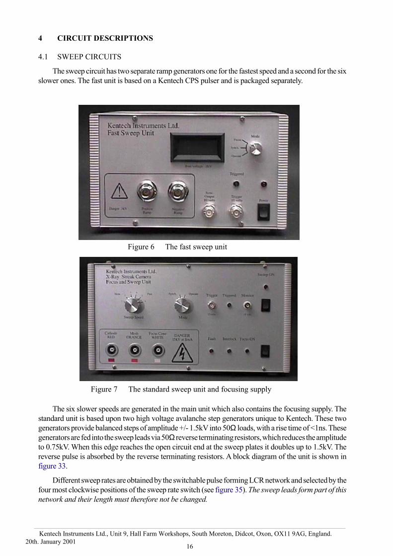
4 CIRCUIT DESCRIPTIONS
4.1 SWEEP CIRCUITS
The sweep circuit has two separate ramp generators one for the fastest speed and a second for the six
slower ones. The fast unit is based on a Kentech CPS pulser and is packaged separately.
The six slower speeds are generated in the main unit which also contains the focusing supply. The
standard unit is based upon two high voltage avalanche step generators unique to Kentech. These two
generators provide balanced steps of amplitude +/- 1.5kV into 50Ω loads, with a rise time of <1ns. These
generators are fed into the sweep leads via 50Ω reverse terminating resistors, which reduces the amplitude
to 0.75kV. When this edge reaches the open circuit end at the sweep plates it doubles up to 1.5kV. The
reverse pulse is absorbed by the reverse terminating resistors. A block diagram of the unit is shown in
figure 33.
Different sweep rates are obtained by the switchable pulse forming LCR network and selected by the
four most clockwise positions of the sweep rate switch (see figure 35). The sweep leads form part of this
network and their length must therefore not be changed.
Figure 6 The fast sweep unit
Figure 7 The standard sweep unit and focusing supply

17
Kentech Instruments Ltd., Unit 9, Hall Farm Workshops, South Moreton, Didcot, Oxon, OX11 9AG, England.
20th. January 2001
A further function of the sweep units is to provide the required bias voltages to define the start of the
sweep (see figure 47). For historical reasons the two units behave slightly differently.
4.1.1 STANDARD SWEEP UNIT OPERATE, SYNCH AND FOCUS
On the slow unit there are two positions ,”SYNCH” and “OPERATE”. In Synch. mode the sweep
starts on just on screen. So one can see the sweep beginning, see section 3.4. In operate mode the sweep
starts well before the screen so that the voltage ramp is in its most linear part when it gets to the screen centre.
In order to focus the unit turn off the sweep section of the supply and arrange a separate trigger for
the intensifier if necessary.
If it is necessary to adjust the synch or operate voltages please see sections 2.3.1 and 2.3.2.
4.1.2 FAST SWEEP UNIT OPERATE, SYNCH AND FOCUS
The fast unit also has a focus position but note that this does not inhibit the trigger so if the intensifier
is triggered from the monitor output (unfortunately also labelled “synch”) arrange for this to be triggered
very late or arrange a separate trigger to the intensifier.
The synch and operate positions are identical circuits but are set with different voltages to define the
sweep start position. The voltages are adjusted on the rear panel. The Sych is normally set to put the start
position at the screen edge and the operate position well off screen. The operate voltage can be
adjusted slightly move the timing of the streak. The corollary is that if these voltages are adjusted then
the timing changes.
4.2 THE FOCUSING SUPPLY
Figure 24 is a block diagram of the focusing supply with circuit details in figure 25. The focusing
potentials are derived from a resistive divider chain, passing a nominal current of 100 µamps. The
operation of this network requires no explanation except to say that the high voltage zener diodes are to
limit the voltages appearing across resistors in the network in the event of a breakdown, thus stopping
damage by excessive dissipation. (The network is shown in Figure 29). The -15kV potential is obtained
from a regulated solid state encapsulated supply. This supply is in turn supplied from a regulated low
voltage DC source.
The focus and mesh potentials can be varied by means of the potentiometer spindles to be found inside
the focusing supply. If they are to be adjusted then an insulated screwdriver must be used, taking great care
to keep fingers away from the potted box and the high voltage connectors.
The potentials may be measured with a high impedance probe. A 1GΩ probe will cause a significant
voltage drop on the mesh and focus outputs and a correction must be made if the true voltages are required.
The specification at the end of this manual quotes the indicated voltages measured sequentially with such
a probe. It does not give the true voltages which may be obtained with bridge measurements.
The fault indicator light is activated if the camera draws any appreciable current from the supply. The
-15kV is obtained from a Astec encapsulated DC/DC converter. A signal is taken from this supply which
is a measure of the power output. A trimmer on the low voltage board sets the threshold at which the
indicator lights in response to this signal. A breakdown is usually accompanied by intermittent changes
in the brightness of the fault lamp.
At the rear of the unit is a connection for an interlock. The centre pin needs to be grounded to the outer
connection to enable the high voltage supplies. This is intended for use with vacuum gauges having
pressure level switches. This feature should on no account be used to turn the unit on and off as it is likely

18
Kentech Instruments Ltd., Unit 9, Hall Farm Workshops, South Moreton, Didcot, Oxon, OX11 9AG, England.
20th. January 2001
that the pressure will damage the camera before the switch in the gauge acts. It is intended purely to prevent
accidental powering up with the pressure too high. An interlock plug with a leads is provided.
The HTs are set to come on slowly (around 10 seconds) to help reduce breakdown
problems.
5 CATHODES
The cathode materials normally recommended for X–ray use are cæsium iodide and gold but for
high time resolution the energy spread from these is too great. We recommend the use of potassium
bromide or potassium iodide. It has also been noted that low density cæsium iodide cathodes exhibit
a tail in the emission after illumination with a very short pulse. Consequently we recommend solid
density cathodes for high time resolution. As these have a very limited lifetime the user will have to
be able to recoat the cathodes supplied regularly or be extremely careful about their exposure to
anything but a clean vacuum.
TRANSFER THE CATHODES SUPPLIED TO AN EVACUATED DESICCATOR AS SOON
AS POSSIBLE AFTER RECEIPT OF THE CAMERA
5.1 CATHODE MANUFACTURE
The most sensitive cathodes we have used are low density cæsium iodide. This material is made
by thermal evaporation in a background atmosphere of argon. The cathode is in the form of a foam,
with a structure scale length of a few microns. The voids in the material allow electrons to escape from
a greater depth. Furthermore the presence of a large electric field in the material causes a cascading
effect resulting in a small amount of gain. Ironically the low density material, with a very large
effective surface area, is most tolerant of atmospheric water vapour. We believe this is because the
absorbed water is quickly lost under vacuum, as a result of the large surface area. Low density
cathodes are, however, not very mechanically robust.
A suitable “recipe” for the production of such cathodes is to evaporate approximately 1-2ccs of
powdered cæsium iodide in a background of 5 millibars of argon. The layout of the deposition
chamber should be roughly as shown in figure 37. The cæsium iodide is carried in the form of a smoke
by convection currents in the background gas. A very uniform cathode can be made by rotating the
substrate during the deposition, see figure 37
6 PHOTEK IMAGE INTENSIFIER AND LAVISION CCD CAMERA
The Photek 40mm flat field image intensifier is supplied with the original equipment
manufacturer’s manual and reference should be made to that in conjunction with these notes.
Similarly the manuals for the LaVision CCD camera should be referred to also.
The CCD camera is supplied ready fitted to a fibre optic demagnifying taper and to the
intensifier. Unless the user wishes to switch to film as a recording medium this assembly need not
be dismantled at all.
6.1 INTERFACING THE INTENSIFIER TO THE STREAK CAMERA
Prior to mounting the intensifier to the streak camera, perform the initial power up test on the
streak camera, see section 3.3.
The intensifier is supplied mounted in a housing with the readout fitted.

19
Kentech Instruments Ltd., Unit 9, Hall Farm Workshops, South Moreton, Didcot, Oxon, OX11 9AG, England.
20th. January 2001
Fig
ure
8T
he
CC
D C
amer
a hea
d w
ith i
nte
nsi
fier
fit
ted.
20
Kentech Instruments Ltd., Unit 9, Hall Farm Workshops, South Moreton, Didcot, Oxon, OX11 9AG, England.
20th. January 2001
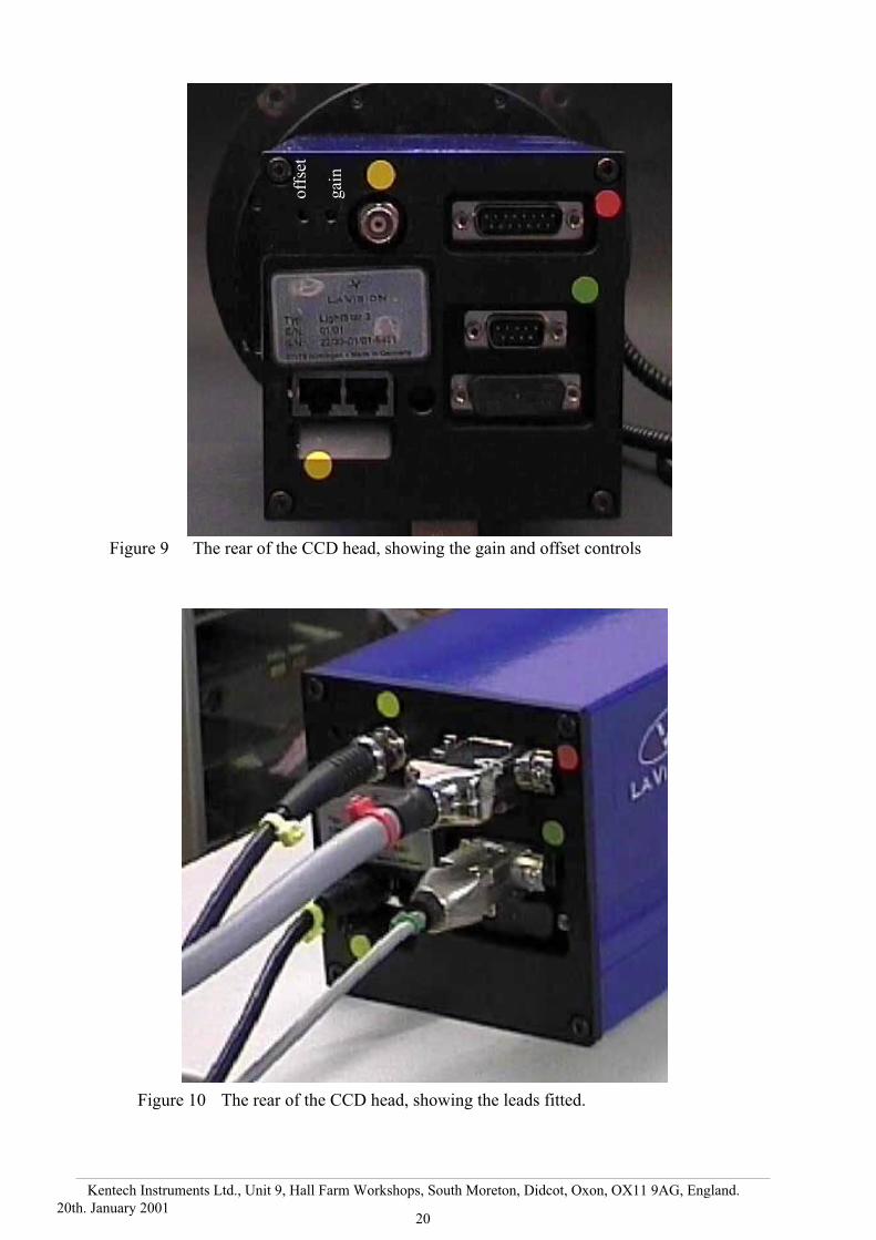
Figure 10 The rear of the CCD head, showing the leads fitted.
off
set
gai
n
Figure 9 The rear of the CCD head, showing the gain and offset controls

21
Kentech Instruments Ltd., Unit 9, Hall Farm Workshops, South Moreton, Didcot, Oxon, OX11 9AG, England.
20th. January 2001
Remove any protective covers from both the intensifier input and streak tube output faces if these
are present. This is best done using a piece of adhesive tape rather than trying to use a sharp object
under the edge of the cover. Keep all hard or sharp objects away from the intensifier.
Make sure that the fibre optic surfaces to be mated (the streak camera output and the intensifier
input windows) are scrupulously clean. If necessary clean with a use once lens tissue with some
suitable solvent cleaner, e.g. low residue alcohol or acetone. Use a single wipe across the face with
a folded tissue and then discard the tissue. If necessary repeat the process. Remember that the fibre
optic faces are image planes and any residue, dirt or damage will appear on the final image data.
Present the intensifier/CCD assembly to the streak tube and slide over the four stubs protruding
from the streak tube. Carefully bring
the two units together. The last few mm
are spring loaded as the intensifier can
move back in the housing slightly. It
will fit in any of four orientations. The
user should decide which way round is
best suited to a particular application
and mount the intensifier accordingly.
However all the data shown here in the
calibration section assumes that the
camera is mounted with its top upper
most and that the focus leads to the
streak tube are lower most.
With the head held on the four
protruding studs, carefully fit and
tighten the four large brass knurled
nuts until the head is firmly held against
the streak tube flange. The nut may be
tightened with a spanner but we have
found finger tightening adequate. Note that as the intensifier is spring loaded the pressure between
the intensifier and the streak tube optics is not related to the tightening of these large brass nuts.
Make sure there is can be unsrestricted airflow around the air inlet and outlet grilles on the sides
of the CCD head, see figure 11.
6.2 INTENSIFIER POWER SUPPLY AND TRIGGERING
The intensifier is connected to its power supply via a cable and a high voltage Fischer plug. Make
sure that the power supply is turned off before fitting the plug.
The intensifier may be triggered from the sweep generators using the monitor/synch. outputs.
Make sure that the edge switch is set to “+ve” on the intensifier power supply. If an alternative trigger
source is used then it should be TTL level and the pulse duration must be less than 300µs. Trigger
signals greater than 300µs may extend the gate time accordingly. Although the manual states that the
rigger pulse should be longer than 100ns we have found that the shorter signals from the sweep units
will trigger the intensifier.
The intensifier gain will rise about 30ns after the trigger is supplied. The phosphor of the streak
tube decays over several hundred microseconds. Triggering the intensifier at the same time as the
standard sweep unit will therefore result in a very small loss of signal. The synch output on the fast
sweep unit is not suitable for triggering the intensifier and alternative triggering should be arranged.
Figure 11 The CCD head, showing the air flow ports

22
Kentech Instruments Ltd., Unit 9, Hall Farm Workshops, South Moreton, Didcot, Oxon, OX11 9AG, England.
20th. January 2001
Before turning off the power to the intensifier supply it is advisable to remove all light
sources from the device, switch the photocathode gating control to “OFF” and the gain to
minimum. In normal use with the intensifier bolted to the streak camera there will be no light into
the intensifier anyway. However, during D.C. focusing there may be light falling on the intensifier
input. This should be removed before switching off.
When the power is removed from the intensifier the voltage on the cathode may not hold the tube
off while the other power rails collapse and a large exposure could result if there is light falling on
the cathode.
The intensifier power supply employs a current limit so that if the tube is over exposed the current
drawn will be limited to protect the tube. On no account should this limit be used generally. It is
for protection in the case of an accident and cannot be relied upon to protect the tube fully.
6.3 CCD READOUT SYSTEM
The readout system consists of the head, supplied attached to the intensifier, a controller, two
PCI cards, several leads and software.
6.3.1 A SUITABLE COMPUTER
A suitable computer will need at least the following specification:-
Ability to run Microsoft™ Windows 98
Three spare PCI slots
Floppy drive
CD Rom drive
Free Serial Port COM 1 (the software can be configured for Com 1 or Com 2)
Free parallel port (or USB if you ask LaVision for a USB dongle)
Figure 12 The PCI cards installed showing the trigger lead.

23
Kentech Instruments Ltd., Unit 9, Hall Farm Workshops, South Moreton, Didcot, Oxon, OX11 9AG, England.
20th. January 2001
A lot of memory, more memory more images can be stored and manipulated. We have found that
128 Mbytes gives adequate resources.
A reasonable size hard disc, as the images are more than 4Mbytes each.
We have found that 37 Gbytes is adequate (probably a lot less would be OK also)
We have found that an 800MHz machine works adequately but a slower one would probably be
adequate.
It is a good idea to have method for backing up the data.
Figure 14 The parallel port Dongle fitted. Figure 15 The rear of the CCD camera power supply
Figure 13 The rear of the computer with camera leads attached and detached.

24
Kentech Instruments Ltd., Unit 9, Hall Farm Workshops, South Moreton, Didcot, Oxon, OX11 9AG, England.
20th. January 2001
6.3.2 SETTING UP THE COMPUTER
With the computer shut down and the power off. Insert the two PCI cards into the PCI bus. The
TTL/I/O card has a piggy back board that uses a third output slot but does not connect to the PCI
interface directly.
There is a trigger lead from the TTL I/O card to the A to D convertor card, make sure that this
does not come off, see figure 58.
Two sockets on the back of the TTL I/O card are linked with a short lead. These are the third and
sixth from the top, see figure 13.
With the camera power and computer power off connect up the CCD camera. There are three
leads from the camera to the computer and one from the camera to the camera controller.
Screw down the leads that have screws requiring screwing down. All the leads are colour coded.
Note that the lead with the green tag goes to the serial port.
Attach the dongle supplied to the parallel port.
6.3.3 SOFTWARE INSTALLATION
Insert the CD ROM and the floppy disc. If installation does not start automatically open the CD
Rom directory and launch the SETUP.EXE application. Follow on screen instructions.
Make a back up copy of the floppy disc. This contains customer settings files which the software
can modify but it is always a goods idea to keep a copy of the original set.
The installation process will require re-booting the computer.
6.3.4 FIRST RUN OF THE SOFTWARE
Turn on the camera controller, Switch the temperature control to “set” set the temperature
indicated on the display to 15°C. Switch the control back to “actual”. If the temperature is
significantly different from 15° C wait until it has stabalised. The first time the software is run it will
ask that you restart it, do so. This is to make sure the relevant components are loaded in sequence and
it does not know the sequence until it is run the first time.
The software should find the dongle and the two PCI cards. Should there be any problems at this
stage check for poor connections to these items and restart the machine from scratch.
Once the software is running there should be a window entitled “Run Experiment”. This enables
the user to take images.
A first time run bug in the system stops the taking of an image at the first attempt after restarting
the machine. This is being worked upon at the time of writing but has proved a little intractable to
sort out.

25
Kentech Instruments Ltd., Unit 9, Hall Farm Workshops, South Moreton, Didcot, Oxon, OX11 9AG, England.
20th. January 2001
When an image is taken all the computer interrupts are disabled. This means that until an image
is acquired the user looses control of the machine. There is a timeout limit set under File/Global
option/Timings. This should be set to 9 seconds. (The actual units will depend upon machine speed).
For normal operation the system needs an external trigger into the top socket on the TTL I/O card.
(positive going TTL level of around 50ms). Attach a suitable trigger signal and attempt to take an
image.
6.4 CCD TIMING AND TRIGGERING
The CCD camera needs a trigger unless it is triggered with software.
The CCD chip needs a trigger to start the image integration and a trigger to stop it. These are
provided by the TTL I/O board supplied through the edge on A3, see figure 16.
In normal use requiring synchronisation to an external event of known duration the best mode
to use is to trigger the camera at the beginning of the integration and let the software turn it off and
then readout the data. It is, however, possible to use hardware to do both.
The input at the top of the TTL I/O board is connected in hardware to the logical input IN1 on
the timing acquisition diagram, see figure 16
The pulse applied to this input should be positive going and at least 3ms before the event to be
recorded. The integration actually starts on the rising edge of A3, but a further 3 ms should be allowed
after this time to allow the electronics to settle.
With the timing as set up in the figure one needs the event at 6 ms after the trigger input. The
trigger pulse should last at least 20 ms, preferably 50ms.
If one knows exactly when the event will occur with respect to the trigger pulse to the CCD
camera system then one can se the third delay stage (the 20ms in the figure) to a suitable value. A lower
value will reduce the dark current signal but one must ensure that the event has happened. Also note
that the event lasts 1.3ms, this the sum of the intensifier gate time and the decay time of the intensifier
phosphor. This is the event that is actually recorded by the CCD camera. The integration ceases on
the falling edge of A3.
So the sequence of events to take a normal image is:-
From the key board/mouse issue a take image command. The software will then clear out the
image in the CCD chip and disable the computer interrupts, then wait for the rigger signal into the
top port on the TTL I/O board. If this is not forthcoming before the timeout value the system will abort
and issue an error message. The interrupts will be e-enabled.
After the trigger command is detected, the system waits 3ms before telling the camera to readout
the move the current image out of the sensitive area of the chip. After a further 23ms the system will
readout the integrated image.
By changing the parameters in the timing acquisition diagram one can make the camera wait for
and end of event command or issue rigger pulses etc. However, note that the dark current signal will
depend upon the integration time so if one uses a configuration that waits for the end of the event the
dark signal could vary from shot to shot.
The software permits the taking of a background signal and automatically subtracting this from
each image. Note however, that this background image should be taken under the same conditions
as the main data, i.e. the same integration time, same intensifier gate width and gain as well as the
same Area of Interest (AOI), should this be reset in the software. The background image may be

26
Kentech Instruments Ltd., Unit 9, Hall Farm Workshops, South Moreton, Didcot, Oxon, OX11 9AG, England.
20th. January 2001
Figure 16 Acquisition Timing window
27
Kentech Instruments Ltd., Unit 9, Hall Farm Workshops, South Moreton, Didcot, Oxon, OX11 9AG, England.
20th. January 2001
averaged over several shots. We recommend that the streak tube focus be turned off but that other
settings allowed to remain the same.
A few points to note. When first switched on the CCD camera head may need to get down to
operating temperature. If one uses the intensifier in DC mode with a continuous light source it is
necessary to increase the integration time to ~200ms to stop overloading of the memory section of
the frame transfer chip. One can stop the system requiring triggers by changing the N=1 in the first
wait window (under acquisition timing) to N=0. One can then take images by continuously grabbing
(F11 on the key board) the intensifier can be run DC and its dark current seen. One can even increase
the integration time to around 1 second (in the third delay window) to see the dark current. When
grabbing continuously one can escape the process by hitting the “escape” key. This will not work for
a single take frame as only the arrival of a trigger or the time out duration is monitored.
Note that in this software the difference between the OK and Apply buttons is that OK closes
the window also. It is necessary to hit one of these buttons to make the software react to changes.
One may save many Acquisition timing configurations and then load them back another time.
It is a good idea not to overwrite those on the floppy provided with the system.
The user should read the manuals that come with the software but here are some general points
to consider.
Once one is happy that the camera is taking suitable images prior to a real data short then take
the relevant background image. The typical pixel count in a background image is around 500 counts.
If it is a lot different from this due to very long integration times one can adjust the offset of the
digitisation process.
If an image is taken with the take image key board command (F10) or thorough the Run
Experiment dialogue box then the image will be placed into the buffer currently active. By default
this is 1 with the background in 10. An L next to a buffer number in the buffer list indicates a locked
buffer.
Before a real shot it is important to set the timeout of a realistic value. This could be many
minutes. This is set in the “Run Experiment” window.
Images should be saved to disc as soon as possible. This can be done by right clicking the buffer
item in the buffer list. Make sure the file format used is suitable. A 16 bit format will be required to
preserve all the data but most PC image manipulation programs will require an 8 bit image.
By using the Sequence summing options (hit Sequence Dialog in the Run Experiment window)
one can set up the system to take one frame, subtract the background and save to disc with a sequential
file name.
There are a few minor bugs in the software. These are being worked upon at the time of writing.
Please report other problems discovered to Kentech or LaVision.
Note that hitting the Escape key can close windows. The “Run Experiment “ window is opened
from the Macro menu. If Macro does not appear but System appears in its stead then a problem has
occurred at start up with the settings files.
When examining images note that profiles can be accessed under both buffer 0 and under each
individual buffer with a right click on the buffer item in the buffer list. Buffers may contain several
images and profiles.
Buffer names and scales are overwritten when an image is grabbed into it. Many of these features
are customerisable by way of the command language (CL).

28
Kentech Instruments Ltd., Unit 9, Hall Farm Workshops, South Moreton, Didcot, Oxon, OX11 9AG, England.
20th. January 2001
Figure 18 A typical screen and Window set.

29
Kentech Instruments Ltd., Unit 9, Hall Farm Workshops, South Moreton, Didcot, Oxon, OX11 9AG, England.
20th. January 2001
6.5 ADJUSTING THE GAIN AND OFFSET
The gain and offset are adjusted at the factory. The gain should not
need adjusting and is set to give a count of around 64,000 maximum, i.e.
when the CCD charge wells are full.
The offset may need adjusting if very different integration times are
to be used.
It takes one second to readout an image. During this time dark
current adds counts to the signal. However short the integration time
there is always a contribution to the signal from this current. Lowering
the temperature about 7 degrees halves the dark current.
The background image count should be around 500 per pixel. If it
is significantly different from this in an unilluminated frame then the
offset should be adjusted. Adjustment of each of these controls can be
done both at the camera head and at the PCI card, through the backplane,
see figures, 9 and 17.
6.6 CONTINUOUS ILLUMINATION
The camera is not designed for continuous
illumination. If there is continuous illumination longer
integration times should be used to give the system
time to sweep out unwanted charge from exposure before the integration period.
6.7 TEMPERATURE CONTROL
The recommended operating temperature is 15°C. If the set value is lower or the airflow is
restricted or the ambient temperature is high then the fans cannot more enough heat from the Chip.
The result is that the controller tries harder to cool the head and just ends up dissipating even more
heat. The result will be an increase in temperature.
If integration times are to be long and a lower dark current required then the ambient temperature
needs to be reduced or some other form of enhancement to the cooling used.
Figure 17 Gain and Offset adjustmentat the computer PCI card
offset
gain

30
Kentech Instruments Ltd., Unit 9, Hall Farm Workshops, South Moreton, Didcot, Oxon, OX11 9AG, England.
20th. January 2001
7 SWITCHING BETWEEN FILM BACK AND CCD READOUT HEAD
If it is necessary to switch from CCD readout to film then the CCD head and fibre taper must
be removed. Here is a list indicating the sequence of events to be followed. This will take about 20
minutes. The reverse process has to be accompanied by realignment of the CCD chip and could take
around 1 hour.
7.1 FITTING THE FILM BACK
When following this procedure mark or note the orientation of each piece as it is removed, this
will aid the reverse operation.
1 Remove the CCD head from the back of the streak tube. Power the head and
intensifier down. Disconnect all leads to the head and the intensifier.
2 Place the unit with the input face down on a suitably clean work bench.
3 Place the controller box (unconnected) adjacent to the head, see figure 19.
4 Remove the eight M3 cap head screws on the middle flange.
5 Lift up the rectangular box of CCD control electronics and place on top of the
controller box. It may be necessary to pull out the ribbon cable that connects the
electronics to the CCD chip. On no account disconnect this lead, just pull out enough
to allow the units to be separated.
5 Remove the three radial M4 countersunk screws from around the base of the circular
blue tube.
6 Lift up the blue tube and re-attach to the black flange (eight M3 cap head screws. It
is important that it is done this way as the ribbon cable must be pulled out of the
electronic casing carefully.
7 You should now have an arrangement as shown in figure 19.
8 Remove the six radial M3 screws from the aluminium body as well as the three M2
screws. This will allow the aluminium piece to slid upwards towards the CCD chip
carrier to which it is spring loaded.
9 Remove the four M5 vertical bolts that pass
trough the back of the finned heat sink on
the CCD chip carrier. Do this progressively,
a little on each one at a time.
10 The aluminium outer housing should now
be able to fall down. It is important that it
falls below the plane of the CCD input face.
11 Slide the Finned heat sink assembly to one
side carefully until the join between the
output face of the fibre taper and the input
of the CCD chip separate. They are held
together by atmospheric pressure and
surface tension. They are oil coupled.
12 Place the CCD chip to one side being careful
not to stress the leads to the electronics
Figure 19 The insides of the CCD head

31
Kentech Instruments Ltd., Unit 9, Hall Farm Workshops, South Moreton, Didcot, Oxon, OX11 9AG, England.
20th. January 2001
package.
13 Lift off the outer aluminium housing.
14 Unscrew the six M2.5 screws around the base of the inner aluminium housing.
Remove the radial grub screws from this housing also.
15 Lift off the outer housing leaving the taper mounted in its aluminium block on top
of the intensifier output window.
16 Gently slide the fibre optic taper off the intensifier similarly to the CCD chip off the
taper output. Note that the windows are around 40mm and it will be necessary to slide
them a long way.
17 Place the taper to one side and store carefully.
18 Clean the output window of the intensifier, removing all races of oil.
19 Fit the film back holder and the three radial knurled screws provided, see figure 38.
With these screws loose the film back holder can slide to and from the intensifier
output face.
20 Remove the dark slide from the film holder and fit the film holder to the film back
holder as shown in figure 38.
21 Fit the assembly to the streak tube when required as for fitting the CCD system to
the streak tube.
22 Pull the film back holder away from the intensifier and tighten the knurled screws.
Insert the dark slide.
23 Open the film back with the clip at one end. Insert a film pack. Close the film back,
and pull out the paper film cover until a small white tap appears.
24 Loosen the three knurled radial screws, remove the dark slide and gently push the
film back onto the intensifier output face. Whilst applying even pressure tighten the
three radial screws. The film is now ready for exposure.
25 The film back may be loaded with film off the film back holder with the dark slide
inserted. Either 667 or 612 Polaroid™ film may be used.
26 Be very careful not to slide the dark slide in when the film back is pushed against the
intensifier output window. This can damage both.
27 Be very careful no to push the film back against the output window with the dark slide
inserted. This can damage both.
7.2 REFITTING THE CCD BACK TO THE INTENSIFIER
This is basically the reverse of the above however there are several extra steps.
When fitting the fibre optic tapers back together they must first be cleaned (as when fitting the
intensifier to the streak tube). In addition a suitable amount of coupling oil should be used between
32
Kentech Instruments Ltd., Unit 9, Hall Farm Workshops, South Moreton, Didcot, Oxon, OX11 9AG, England.
20th. January 2001
the faces. Note that this oil must not be used between the streak tube and intensifier and there is no
possibility of sliding them apart and they cannot be pulled apart.
In addition it is necessary to have the CCD chip in the correct position and orientation on the back
of the taper. The adjustments for this are the radial M3 screws on the aluminium body. It is also
possible to move the taper slightly within the inner housing.
In order to see the alignment it is necessary to run the intensifier and CCD head with the head
disassembled. In addition it is necessary to fit some alignment marker to the intensifier input face so
that its orientation can be measured. A piece of graph paper is quite good. It can be aligned with the
intensifier mounting screws around the input face.
With the CCD running outside the blue tube the fans cannot cool the chip. This can result in some
image problems at the top of the image and in any case should the chip heat up significantly it should
be allowed to cool before proceeding. The temperature is indicated on the controller with the switch
set to “actual”. It should run at 15°C.
7.3 USING THE INTENSIFIER WITH FILM
Wafer tubes, as supplied here, use cathode gating to turn them on and off. Consequently the
phosphor is exposed to dark current from the microchannel plate if the tube is left on but ungated.
Although the tube is supplied so that film can be left in contact with the output window without
exposure this will only be good for a limited time, several minutes. The intensifier may be turned off
completely but there is always a risk of flashes when the tube is turned on again prior to exposure.
The user is left to establish a good procedure in order to achieve unfogged film for their particular
application. After exposure, the film back holder should be unclamped and the holder withdrawn
partially from the intensifier. Do not undo the clamp screws fully or the holder will come right off
and lead to ruining of the film. With the holder away from the intensifier the film may be drawn
through and processed, or the dark slide may be inserted.
Although the system is not designed to cope with standard negative film, many users do use it
with such. It is possible to mount a piece of film in front of a polaroid film so that both instant and
higher quality output are available on one shot. The increase in light level required for standard film
(it does depend upon the film) roughly compensates for the attenuation of the light going through the
standard film so that the polaroid is exposed satisfactorily.
8 DATA SHEETS
8.1 STATIC FOCUSING
Camera type LMXRSC
Camera number J00*****Customer
The Czech Republic
Date tested 21st. February 2001
Phosphor type (P11 or P20) P20
33
Kentech Instruments Ltd., Unit 9, Hall Farm Workshops, South Moreton, Didcot, Oxon, OX11 9AG, England.
20th. January 2001
Focus potentials as measured with 1000MΩ probe.
Cathode 14.879 kV
Mesh 10.224 kV
Focus 11.22 kV
Static deflection sensitivity (with above potentials):
+/- 17.54 Volts mm-1 on intensifier phosphor
8.2 SWEEP CIRCUITS
This sweep circuit has been set up for non standard sweep rates.
Sweep speeds, nominal.
Setting V ns-1 ps mm-1 pixels ns-1
Speed 1 18.9 928 35.7
Speed 2 93.4 187.8 175
Speed 3 262.2 66.9 493.4
Speed 4 509.6 34.42 960
Speed 5 1,012 17.33 1,900
Speed 6 2,036 8.62 3,830
Fast Box 14,460 1.21* 27,000*
*Note, experience indicates that true sweep speeds are around 6.53 pixels ps-1 or 5ps mm-1.
8.3 TRIGGER DELAYS
The time between a fast trigger signal arriving at the trigger input of the sweep generator and
the ramp voltage reaching the voltage which corresponds to screen centre is given below. Further
allowance needs to be made for the time of flight of x-rays from the target to the cathode and for the
flight time of photoelectrons from the cathode to the sweep plates (around 1.75ns in a low
magnification camera).
Sweep 1 74ns
Sweep 2 37ns
Sweep 3 35.8ns
Sweep 4 32ns
Sweep 5 31ns
Sweep 6 30ns
Fast Box 16ns
8.4 BIAS VOLTAGES
Standard sweep unit
Bias SYNCH ±239 volts
Bias OPERATE sweeps 1 through 6 ±720 volts
Fast sweep box
Bias SYNCH ±250 volts
Bias OPERATE ±1500 volts
34
Kentech Instruments Ltd., Unit 9, Hall Farm Workshops, South Moreton, Didcot, Oxon, OX11 9AG, England.
20th. January 2001
0
2
4
6
8
10
12
-50 0 50 100 150 200 250 300 350
Monitor Waveform
mon
itor
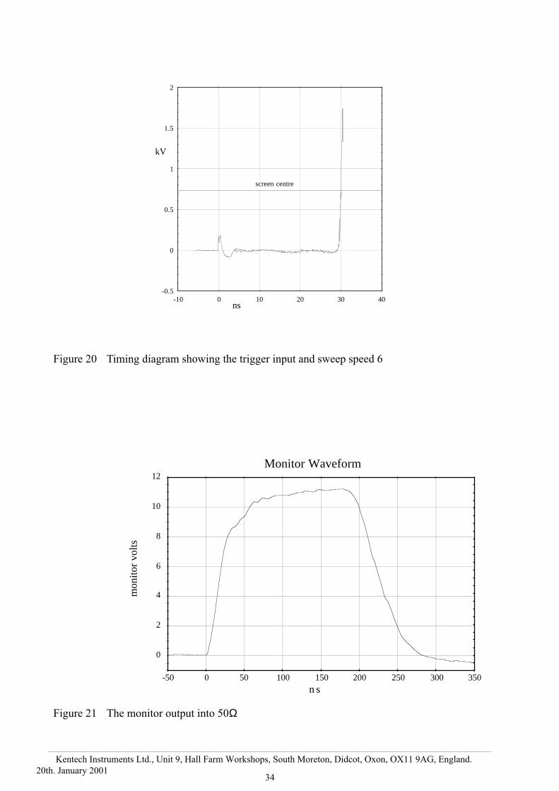
volts
n s
Figure 20 Timing diagram showing the trigger input and sweep speed 6
Figure 21 The monitor output into 50Ω
-0.5
0
0.5
1
1.5
2
-10 0 10 20 30 40ns
kV
screen centre

35
Kentech Instruments Ltd., Unit 9, Hall Farm Workshops, South Moreton, Didcot, Oxon, OX11 9AG, England.
20th. January 2001
Fig
ure
22
Co
nn
ecti
on
s, i
nte
rnal
10 M
10 M
Phos
phor
- ve
ram
p+
ve
bias
'N' t
ype
conn
ecto
r
blac
kSw
eep
Plat
es
Zoo
m e
lect
rode
Ano
de
Mes
h
Focu
s
Cat
hode
+ve
ram
p-
ve b
ias
'N' t
ype
conn
ecto
rre
d

36
Kentech Instruments Ltd., Unit 9, Hall Farm Workshops, South Moreton, Didcot, Oxon, OX11 9AG, England.
20th. January 2001
Fig
ure 2
3C
on
nectio
ns, ex
ternal
+sw
eep & -ve bias
-sweep &
+ve bias
Blue
White
Orange
Phosphor
Tim
e
Flying eht
*Note: T
he direction of the sweep
may be
reversed depending uponintensifier type.
*

37
Kentech Instruments Ltd., Unit 9, Hall Farm Workshops, South Moreton, Didcot, Oxon, OX11 9AG, England.
20th. January 2001
Fig
ure
24
Focu
sing s
upply
, blo
ck d
iagra
m
IEC
Faul
t (ov
erlo
ad)
Det
ecto
rca
thod
e
focu
s
mes
h Focu
s D
ivid
er C
hain
EH
T -
15 k
Vol
ts I
nver
ter
Ast
ec
Falt
Sen
se
Gro
und
Inhi
bit
L N
Uni
vers
al 2
4 vo
ltsu
pply
LE
D
Vac
uum
inte
rloc
kse
nse
vacu
um in
terl
ock
shor
t to
enab
le

38
Kentech Instruments Ltd., Unit 9, Hall Farm Workshops, South Moreton, Didcot, Oxon, OX11 9AG, England.
20th. January 2001
Fig
ure 2
5F
ocu
s Un
it

39
Kentech Instruments Ltd., Unit 9, Hall Farm Workshops, South Moreton, Didcot, Oxon, OX11 9AG, England.
20th. January 2001
Fig
ure
26
EH
T c
ontr
ol
boar
d c
om
ponen
ts

40
Kentech Instruments Ltd., Unit 9, Hall Farm Workshops, South Moreton, Didcot, Oxon, OX11 9AG, England.
20th. January 2001
Fig
ure 2
7E
HT
bo
ard E
HT
tracks to
p

41
Kentech Instruments Ltd., Unit 9, Hall Farm Workshops, South Moreton, Didcot, Oxon, OX11 9AG, England.
20th. January 2001
Fig
ure
28
EH
T b
oar
d E
HT
tra
cks
bott
om

42
Kentech Instruments Ltd., Unit 9, Hall Farm Workshops, South Moreton, Didcot, Oxon, OX11 9AG, England.
20th. January 2001
Fig
ure 2
9D
ivid
er netw
ork
43
Kentech Instruments Ltd., Unit 9, Hall Farm Workshops, South Moreton, Didcot, Oxon, OX11 9AG, England.
20th. January 2001
Fig
ure
30
Sw
eep
po
wer
su
pp
ly c
ircu
it

44
Kentech Instruments Ltd., Unit 9, Hall Farm Workshops, South Moreton, Didcot, Oxon, OX11 9AG, England.
20th. January 2001
Fig
ure 3
1S
weep
pow
er supply
com
ponen
ts

45
Kentech Instruments Ltd., Unit 9, Hall Farm Workshops, South Moreton, Didcot, Oxon, OX11 9AG, England.
20th. January 2001
Fig
ure
32
Sw
eep
po
wer
su
pp
ly t
rack
s

46
Kentech Instruments Ltd., Unit 9, Hall Farm Workshops, South Moreton, Didcot, Oxon, OX11 9AG, England.
20th. January 2001
Fig
ure 3
3S
weep
un
it, blo
ck d
iagram
2 amp
-1kV+
1kV
Bias
Switch
Ram
pO
utputs
Tim
ingSw
itch2 off
KT
106
+ve StepG
eneratorK
T111/P
-ve StepG
eneratorK
T111/N
Balance
Trigger and
Monitor
KT
101
TriggerInput
Monitor
Output
+2kV
-2kV
500 volts
LN
IEC
filteruniversalpow
er supplyL
ow voltage
linearregulator
12volts
+ and -
High voltageinverters
47
Kentech Instruments Ltd., Unit 9, Hall Farm Workshops, South Moreton, Didcot, Oxon, OX11 9AG, England.
20th. January 2001
Fig
ure
34
Sw
eep u
nit
Tri
gger
boar
d (
KT
101)
270
Mon
itor 22
0
100
100
15V
1n
100V
200V
200V
1n
1n
10n
+50
0V
1M5
3M3
3M3
15V
100
10k
2M
100
* *
100
1n
1n 1n
Tri
gger
Inp
ut O
utpu
ts to
Fas
t Sw
eep
Boa
rds
Sw
eep
bala
nce
Tri
gger
Bia
s Se
t
* S
elec
ted
Tri
gger
Tra
nsis
tors
Ferrite Bead
To
slow
ram
p bo
ard
48
Kentech Instruments Ltd., Unit 9, Hall Farm Workshops, South Moreton, Didcot, Oxon, OX11 9AG, England.
20th. January 2001
Fig
ure 3
5S
weep
un
it timin
g sw
itch (K
T1
06
/mo
dified
rates)
IN from
avalanchestack
OU
T to
sweep
output
6.8µH
2.2µH
0.27µH
0.1µH
10µH
0.68µH0.27µH
1µH
4722
220
330
2247
4747 4747 22
All capacitors approx 8pf , form
ed from double
sided pcb 15mm
by 20mm

49
Kentech Instruments Ltd., Unit 9, Hall Farm Workshops, South Moreton, Didcot, Oxon, OX11 9AG, England.
20th. January 2001
Fig
ure
36
Cat
hode/
mes
h a
ssem
bly
Cla
mp
Hou
sing
PTFE
Cla
mp
ring
Cat
hode
con
nect
ion
and
cont
act r
ing
Cat
hode
on
slit
with
act
ive
surf
ace
dow
nwar
ds
PTFE
spa
cer
Thi
n on
e fo
r H
igh
time
reso
lutio
nT
hick
one
for
Low
tim
e re
solu
tion
Mes
h w
ith s
urfa
ce u
pper
mos
t
Mes
h co
nnec
tion
and
cont
act r
ing
Snou
t
cat
hode
and
mes
h ou
tline

50
Kentech Instruments Ltd., Unit 9, Hall Farm Workshops, South Moreton, Didcot, Oxon, OX11 9AG, England.
20th. January 2001
Fig
ure 3
7L
ow
Den
sity cath
ode m
anufactu
re
View
ing Window
convection current
cathode support (not to block valve)
300 mm
typical
300 mm typical
Argon backfilling
line high current evaporator supply
isolation valve
roughing to 0.1 torr is adequate
safetyshield
to pump
Mo or W
'boat' containingC
sI
51
Kentech Instruments Ltd., Unit 9, Hall Farm Workshops, South Moreton, Didcot, Oxon, OX11 9AG, England.
20th. January 2001
Figure 38 The Polaroid film back can be fitted to the intensifier.
The back takes film types 667 or 612. The CCD camera and fibre optic taper must be
removed from the rear of the intensifier. The three radial knurled screws are used to clamp
the film back in position. In normal use these are not removed, just slackened so that the film
back can be slid away from the intensifier to allow the film to be pulled through. DO NOT
ATTEMPT TO PULL THE FILM THROUGH WHEN THE FILM IS IN CONTACT WITH
THE INTENSIFIER.
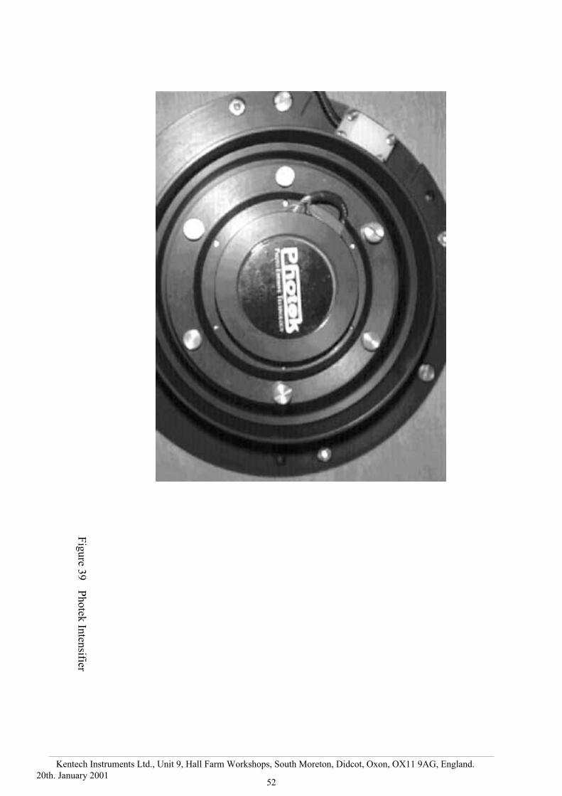
52
Kentech Instruments Ltd., Unit 9, Hall Farm Workshops, South Moreton, Didcot, Oxon, OX11 9AG, England.
20th. January 2001
Fig
ure 3
9P
ho
tek In
tensifier

53
Kentech Instruments Ltd., Unit 9, Hall Farm Workshops, South Moreton, Didcot, Oxon, OX11 9AG, England.
20th. January 2001
15
12
96
30
-3
-6
-9
-12
mm
15
12
96
30
-3
-6
-9
-12
mm
Ver
tica
l
cali
bra
tion
Hori
zonta
l
cali
bra
tion
Fig
ure
40
Lin
ear
cali
bra
tion l
ineo
uts
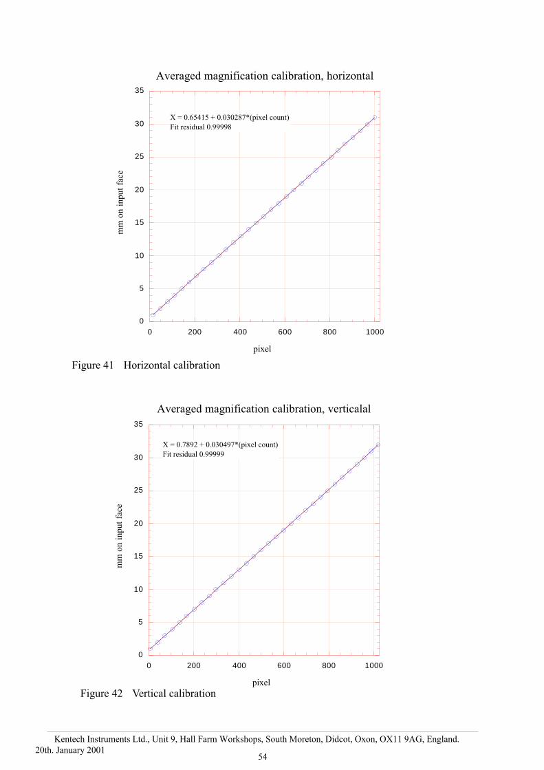
54
Kentech Instruments Ltd., Unit 9, Hall Farm Workshops, South Moreton, Didcot, Oxon, OX11 9AG, England.
20th. January 2001
0
5
10
15
20
25
30
35
0 200 400 600 800 1000
Averaged magnification calibration, horizontal
mm
on
in
pu
t fa
ce
pixel
X = 0.65415 + 0.030287*(pixel count)
Fit residualZ0.99998
0
5
10
15
20
25
30
35
0 200 400 600 800 1000
Averaged magnification calibration, verticalal
mm
on
in
pu
t fa
ce
pixel
X = 0.7892 + 0.030497*(pixel count)
Fit residualZ0.99999
Figure 41 Horizontal calibration
Figure 42 Vertical calibration

55
Kentech Instruments Ltd., Unit 9, Hall Farm Workshops, South Moreton, Didcot, Oxon, OX11 9AG, England.
20th. January 2001
Fig
ure
43
Hori
zonta
l st
atic
res
olu
tion e
stim
ate
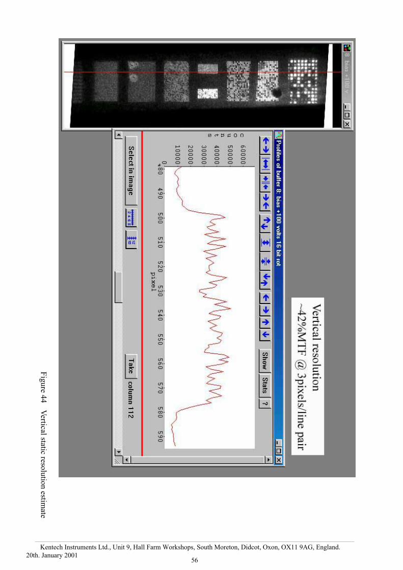
56
Kentech Instruments Ltd., Unit 9, Hall Farm Workshops, South Moreton, Didcot, Oxon, OX11 9AG, England.
20th. January 2001
Fig
ure 4
4V
ertical static resolu
tion estim
ate

57
Kentech Instruments Ltd., Unit 9, Hall Farm Workshops, South Moreton, Didcot, Oxon, OX11 9AG, England.
20th. January 2001
Fig
ure
45
Sta
tic
def
lect
ion s
ensi
tivit
y m
easu
rem
ent

58
Kentech Instruments Ltd., Unit 9, Hall Farm Workshops, South Moreton, Didcot, Oxon, OX11 9AG, England.
20th. January 2001
0
200
400
600
800
1000
-300 -200 -100 0 100 200 300
Ho
rizo
nta
l P
ixel
s
Volts ±
X(pixels) = 526.44 + 1.882*(volts)
Fit residualZ0.99997
Basic streak tube sensitivity = (pixels/volt) x (mm/pixel)-1
= (1.882 x 0.030287)-1 V/mm
= 17.54V/mm
Volts are defined as simultaneous positive and negative voltages to each plate.
Figure 46 Static deflection sensitivity results

59
Kentech Instruments Ltd., Unit 9, Hall Farm Workshops, South Moreton, Didcot, Oxon, OX11 9AG, England.
20th. January 2001
0
0.5
1
1.5
0 2 0 4 0 6 0 8 0 100
Speed 1
kV
n s
screen right
screen left
Y = M0 + M1*XM0 -0.066261M1 0.018967
0
0.5
1
1.5
2
0 5 10 15 20
kV
ns
screen right
screen left
Y = M0 + M1*XM0 -0.24787M1 0.093424
speed 2
Figure 47 Sweep speed 1 measurement
Figure 48 Sweep speed 2 measurement
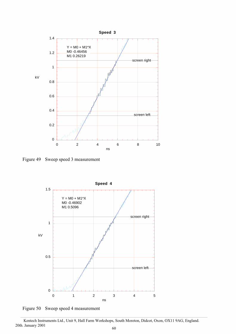
60
Kentech Instruments Ltd., Unit 9, Hall Farm Workshops, South Moreton, Didcot, Oxon, OX11 9AG, England.
20th. January 2001
0
0.2
0.4
0.6
0.8
1
1.2
1.4
0 2 4 6 8 10
Speed 3
kV
ns
screen right
screen left
Y = M0 + M1*XM0 -0.46456M1 0.26219
0
0.5
1
1.5
0 1 2 3 4 5
Speed 4
kV
ns
Y = M0 + M1*XM0 -0.46902M1 0.5096
screen right
screen left
Figure 49 Sweep speed 3 measurement
Figure 50 Sweep speed 4 measurement
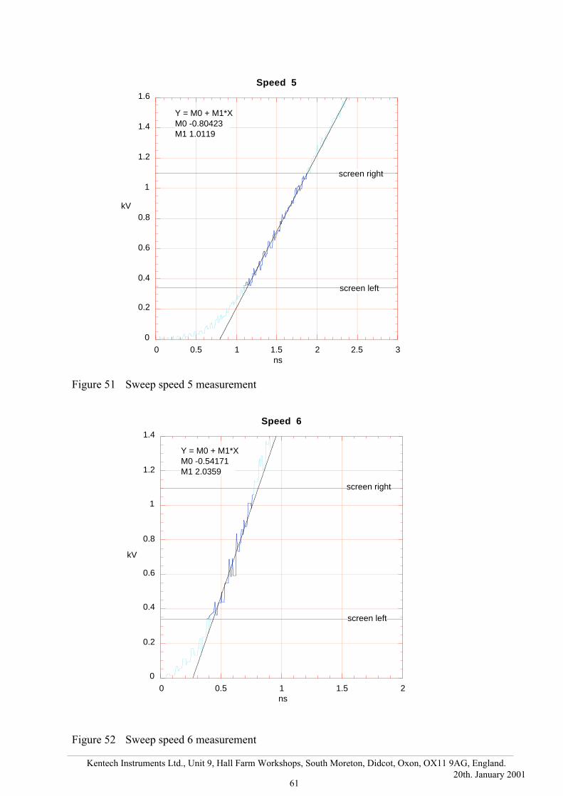
61
Kentech Instruments Ltd., Unit 9, Hall Farm Workshops, South Moreton, Didcot, Oxon, OX11 9AG, England.
20th. January 2001
0
0.2
0.4
0.6
0.8
1
1.2
1.4
0 0.5 1 1.5 2
Speed 6
kV
ns
screen right
screen left
Y = M0 + M1*XM0 -0.54171M1 2.0359
0
0.2
0.4
0.6
0.8
1
1.2
1.4
1.6
0 0.5 1 1.5 2 2.5 3
Speed 5
kV
ns
screen right
screen left
Y = M0 + M1*XM0 -0.80423M1 1.0119
Figure 51 Sweep speed 5 measurement
Figure 52 Sweep speed 6 measurement

62
Kentech Instruments Ltd., Unit 9, Hall Farm Workshops, South Moreton, Didcot, Oxon, OX11 9AG, England.
20th. January 2001
The fast sweep box outputs. 500 volts div-1 into 50Ω. When operated into the sweep
plates this will deliver twice this voltage.
The voltage ramp indicated here is around 14.46V ps-1 and this might be expected to give
a sweep rate of 27pixels ps-1 at CCD or 1.21 ps mm-1 at the streak tube output. However,
experience indicates that true sweep speeds are around 6.53 pixels ps-1 or 5ps mm-1. This is
because the ramp rises on the same time scale as the duration of the electrons in the ramp
region. This produces a non–conservative force and the resulting deflection is significantly
reduced.
Figure 54 The two rampssuperimposed showing the long timehistory.
-2
-1.5
-1
-0.5
0
0.5
1
1.5
2
-2 -1 0 1 2 3 4
kV
ns
Figure 53 The two fast ramps superimposed showing the rise time
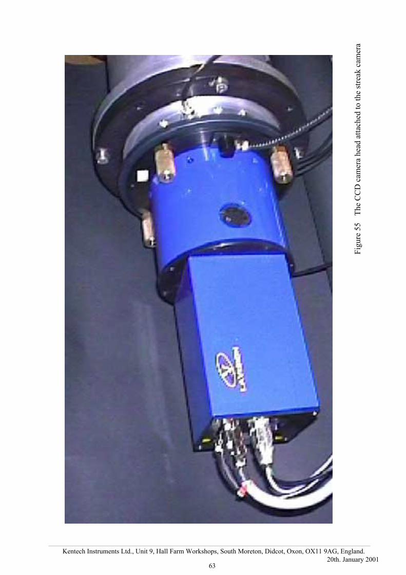
63
Kentech Instruments Ltd., Unit 9, Hall Farm Workshops, South Moreton, Didcot, Oxon, OX11 9AG, England.
20th. January 2001
Fig
ure
55
The
CC
D c
amer
a hea
d a
ttac
hed
to t
he
stre
ak c
amer
a
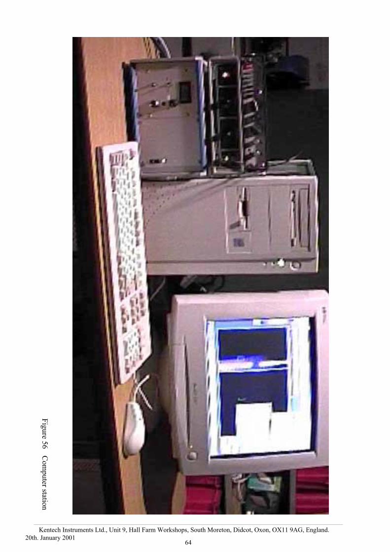
64
Kentech Instruments Ltd., Unit 9, Hall Farm Workshops, South Moreton, Didcot, Oxon, OX11 9AG, England.
20th. January 2001
Fig
ure 5
6C
om
pu
ter station

65
Kentech Instruments Ltd., Unit 9, Hall Farm Workshops, South Moreton, Didcot, Oxon, OX11 9AG, England.
20th. January 2001
Fig
ure
57
The
A t
o D
conver
tor
PC
I ca
rd
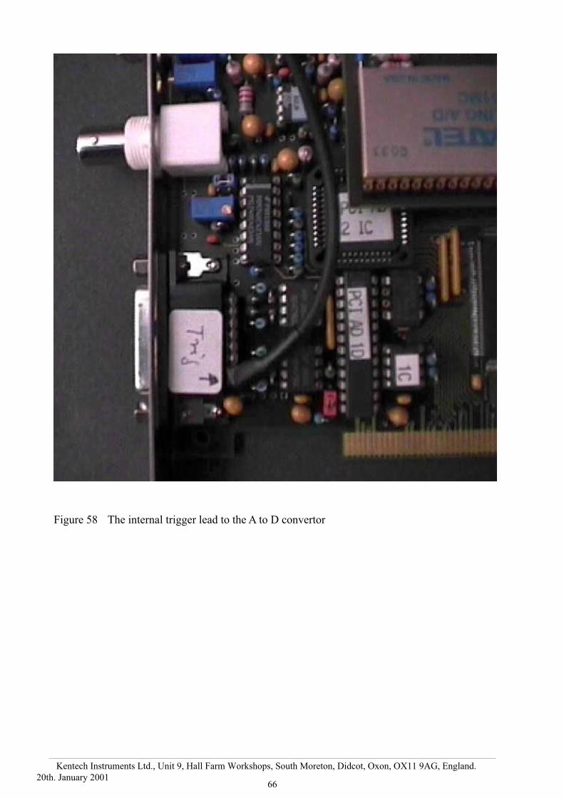
66
Kentech Instruments Ltd., Unit 9, Hall Farm Workshops, South Moreton, Didcot, Oxon, OX11 9AG, England.
20th. January 2001
Figure 58 The internal trigger lead to the A to D convertor

67
Kentech Instruments Ltd., Unit 9, Hall Farm Workshops, South Moreton, Didcot, Oxon, OX11 9AG, England.
20th. January 2001
Figure 59 The Intensifier cable gland.
It may be rotated by slackening the screws underneath.

68
Kentech Instruments Ltd., Unit 9, Hall Farm Workshops, South Moreton, Didcot, Oxon, OX11 9AG, England.
20th. January 2001
Fig
ure 6
0In
tensifier p
ow
er sup
ply

69
Kentech Instruments Ltd., Unit 9, Hall Farm Workshops, South Moreton, Didcot, Oxon, OX11 9AG, England.
20th. January 2001
1
6
4
53
2
blue
yellowblack
green+red
not used
not used
Figure 61 Intensifier lead pin out

70
Kentech Instruments Ltd., Unit 9, Hall Farm Workshops, South Moreton, Didcot, Oxon, OX11 9AG, England.
20th. January 2001
3RD. ANGLE PROJECTION
SURFACETEXTURE
TOL DRAWN
MATERIAL FINISH
KENTECH INSTRUMENTS LTD. SCALEDIMS IN mm
Issue Date MOD
1.6 ±0.12 AKLDB
CLEANBRASS NAVALB
CD
E
2:1
8-8-84
4-12-00 Slot Added forgrazing incidence
2.5
2.5
2732
3.5
2
Ø32
5
Ø39.8
1.0 RadiusTypically
Cathode for XRSC 4A0725
4A0725
A
B
CD
SectionCD
SectionAB
VERYIMPORTANTRound off sothat there are nosharp edges
20
0.5
8-12-00 20mm slot depth added
Figure 62 Engineering drawing for cathode with normal slit and low angle of incidence option
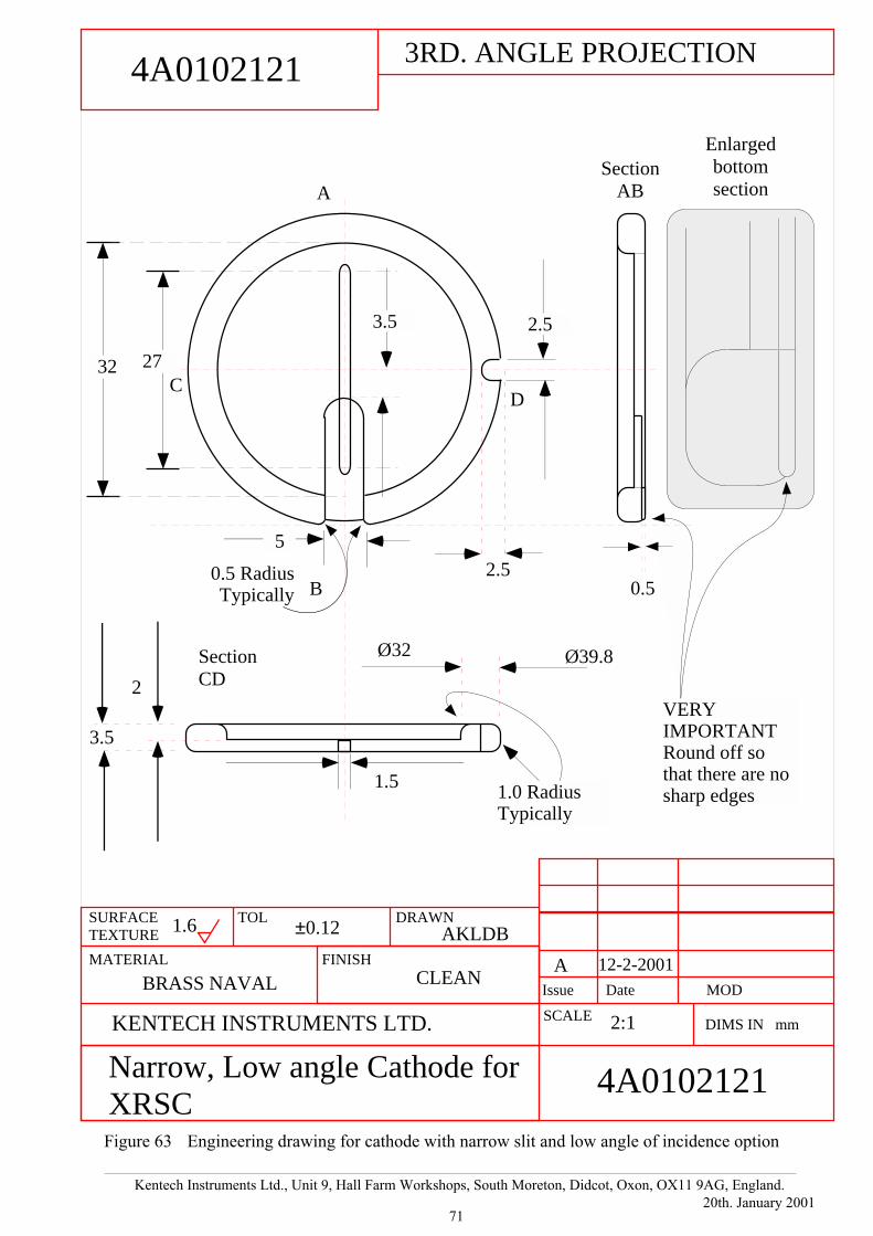
71
Kentech Instruments Ltd., Unit 9, Hall Farm Workshops, South Moreton, Didcot, Oxon, OX11 9AG, England.
20th. January 2001
3RD. ANGLE PROJECTION
SURFACETEXTURE
TOL DRAWN
MATERIAL FINISH
KENTECH INSTRUMENTS LTD. SCALE
Issue Date MOD
2.5
2.5
2732
3.5
2
Ø32
1.5
Ø39.8
Narrow, Low angle Cathode forXRSC
4A0102121
A
B
CD
SectionCD
SectionAB
5
0.5
12-2-2001
4A0102121
A
0.5 RadiusTypically
Enlargedbottomsection
DIMS IN mm
1.6 ±0.12 AKLDB
CLEANBRASS NAVAL
2:1
VERYIMPORTANTRound off sothat there are nosharp edges1.0 Radius
Typically
3.5
Figure 63 Engineering drawing for cathode with narrow slit and low angle of incidence option
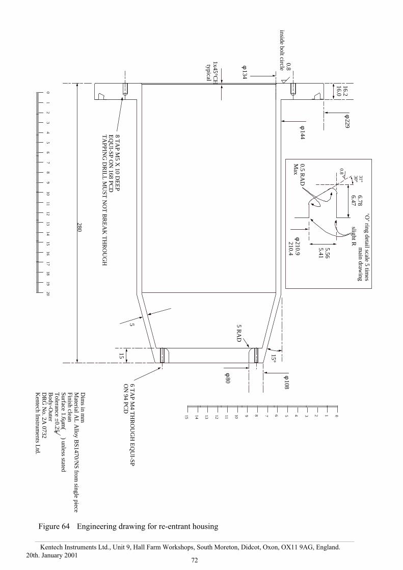
72
Kentech Instruments Ltd., Unit 9, Hall Farm Workshops, South Moreton, Didcot, Oxon, OX11 9AG, England.
20th. January 2001
16.216.0
φ 229φ 144
φ 108
φ 80
φ 134
5
15°
5 RA
D
1x45°CH
typical
8 TA
P M5 X
10 DE
EP
EQ
UI-SP O
N 168 PC
DT
APPIN
G D
RIL
L M
UST
NO
T B
RE
AK
TH
RO
UG
H
31°30°
6.786.47
5.565.41
φ 210.9 210.4
‘O’ ring detail scale 5 tim
esm
ain drawing
0.8inside bolt circle
6 TA
P M4 T
HR
OU
GH
EQ
UI-SP
ON
94 PCD
15
Dim
s in mm
Material A
L A
lloy BS1470/N
S from single piece
Finish cleanSurface 1.6µm
( ) unless statedT
olerance ±0.25
Body-O
uterD
RG
No. 2A
0732K
entech Instruments L
td.
01
23
45
67
89
1011
1213
1415
1617
1819
20
0123456789101112131415
280
0.5 RA
DM
ax
slight R
0.8
Figure 64 Engineering drawing for re-entrant housing

9 SYSTEM EQUIPMENT LIST
1 Streak tube assembly comprising
1(a) Tube in re-entrant housing with flying focusing leads, main ‘O ring fitted.
1(b) Magnetic screen (normally fits round Streak tube assembly).
2 Nylon transit end cover
3 Clamp ring
4 Meshes (3 off)
5 Slit plates (3 off)
6 Cathodes (3off) the two from Luxel are packed separately.
7 PTFE spacer rings 2 off plus spares
8 Spare shorter snout
9 Spare shorter snout clamp
10 Combined focusing supply and sweep unit.
11 Sweep/bias feed leads, (1 pair) N type to N type
12 Vacuum Interlock flying lead to lead Lemo 00
13 Fast Sweep unit.
14 4 large knurled nuts.
15 Film attachment comprising
15(a) Polaroid film holder
16(b) Film back for intensifier
15(c) Knurled screws to clamp film back 3 off
16 Tool kit with trimmer tool
17 Spare screws
18 Six IEC to IEC power leads
19 Six way IEC power adapter
20 IEC, European power lead
21 PCI A to D convertor card
22 PCI TTL I/O card
23 Trigger lead to link the two PCI cards
24 BNC to Lemo leads 3m long 2 off
25 Camera lead assembly
26 Camera Head with intensifier and cover plate.
27 CD ROM of software
28 Floppy Disc with customer settings.
29 CR ROM of web site and manual
30 Streak Camera manual
31 Software manual
32 Flamestar3 manual
33 Command Language manual
34 Photek Intensifier Power supply.
35 Photek Intensifier manual
36 Intensifier trigger lead BNC to BNC
37 Parallel port Dongle
Items checked