keeline operation & maintenance manual · annual recertification in accordance with bs en 365...
TRANSCRIPT

S A F E T Y A T T H E H I G H E S T L E V E L
KeeLine Operation & Maintenance Manual

2
KeeLine Horizontal Life Line
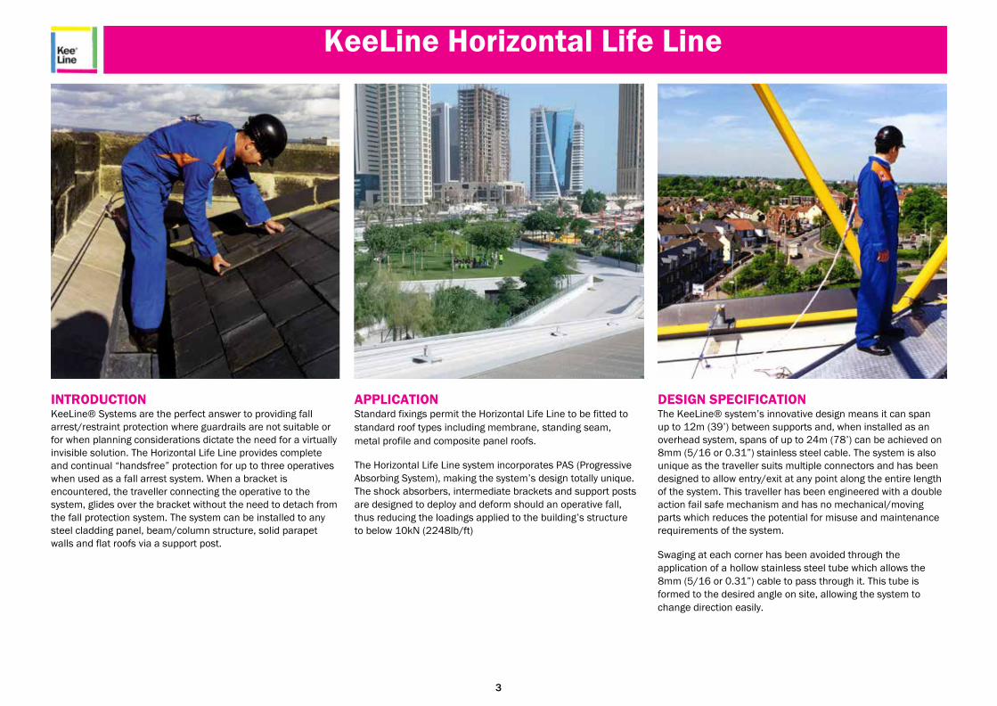
INTRODUCTION KeeLine® Systems are the perfect answer to providing fall
arrest/restraint protection where guardrails are not suitable or
for when planning considerations dictate the need for a virtually
invisible solution. The Horizontal Life Line provides complete
and continual “handsfree” protection for up to three operatives
when used as a fall arrest system. When a bracket is
encountered, the traveller connecting the operative to the
system, glides over the bracket without the need to detach from
the fall protection system. The system can be installed to any
steel cladding panel, beam/column structure, solid parapet
walls and flat roofs via a support post.
APPLICATION Standard fixings permit the Horizontal Life Line to be fitted to
standard roof types including membrane, standing seam,
metal profile and composite panel roofs.
The Horizontal Life Line system incorporates PAS (Progressive
Absorbing System), making the system’s design totally unique.
The shock absorbers, intermediate brackets and support posts
are designed to deploy and deform should an operative fall,
thus reducing the loadings applied to the building’s structure
to below 10kN (2248lb/ft)
DESIGN SPECIFICATION The KeeLine® system’s innovative design means it can span
up to 12m (39’) between supports and, when installed as an
overhead system, spans of up to 24m (78’) can be achieved on
8mm (5/16 or 0.31”) stainless steel cable. The system is also
unique as the traveller suits multiple connectors and has been
designed to allow entry/exit at any point along the entire length
of the system. This traveller has been engineered with a double
action fail safe mechanism and has no mechanical/moving
parts which reduces the potential for misuse and maintenance
requirements of the system.
Swaging at each corner has been avoided through the
application of a hollow stainless steel tube which allows the
8mm (5/16 or 0.31”) cable to pass through it. This tube is
formed to the desired angle on site, allowing the system to
change direction easily.
3
KeeLine Horizontal Life Line
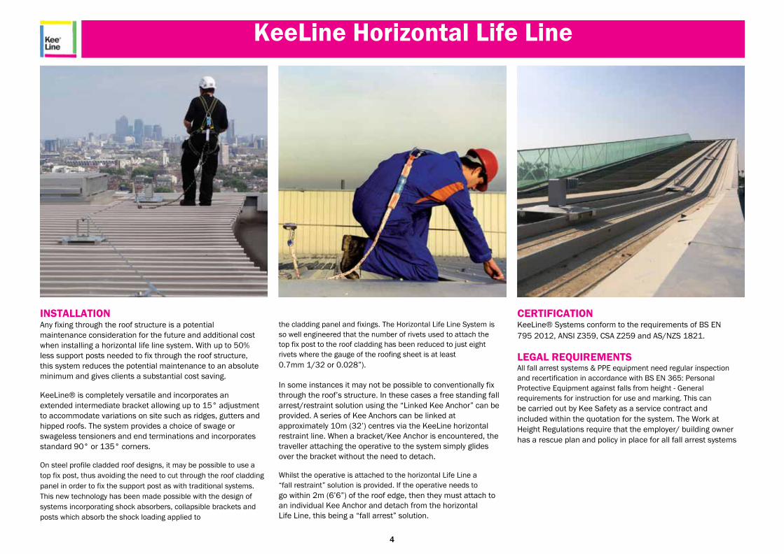
INSTALLATION Any fixing through the roof structure is a potential
maintenance consideration for the future and additional cost
when installing a horizontal life line system. With up to 50%
less support posts needed to fix through the roof structure,
this system reduces the potential maintenance to an absolute
minimum and gives clients a substantial cost saving.
KeeLine® is completely versatile and incorporates an
extended intermediate bracket allowing up to 15° adjustment
to accommodate variations on site such as ridges, gutters and
hipped roofs. The system provides a choice of swage or
swageless tensioners and end terminations and incorporates
standard 90° or 135° corners.
On steel profile cladded roof designs, it may be possible to use a
top fix post, thus avoiding the need to cut through the roof cladding
panel in order to fix the support post as with traditional systems.
This new technology has been made possible with the design of
systems incorporating shock absorbers, collapsible brackets and
posts which absorb the shock loading applied to
the cladding panel and fixings. The Horizontal Life Line System is
so well engineered that the number of rivets used to attach the
top fix post to the roof cladding has been reduced to just eight
rivets where the gauge of the roofing sheet is at least 0.7mm 1/32 or 0.028”).
In some instances it may not be possible to conventionally fix
through the roof’s structure. In these cases a free standing fall
arrest/restraint solution using the “Linked Kee Anchor” can be
provided. A series of Kee Anchors can be linked at
approximately 10m (32’) centres via the KeeLine horizontal
restraint line. When a bracket/Kee Anchor is encountered, the
traveller attaching the operative to the system simply glides
over the bracket without the need to detach.
Whilst the operative is attached to the horizontal Life Line a
“fall restraint” solution is provided. If the operative needs to go within 2m (6’6”) of the roof edge, then they must attach to
an individual Kee Anchor and detach from the horizontal
Life Line, this being a “fall arrest” solution.
CERTIFICATION KeeLine® Systems conform to the requirements of BS EN
795 2012, ANSI Z359, CSA Z259 and AS/NZS 1821.
LEGAL REQUIREMENTS All fall arrest systems & PPE equipment need regular inspection
and recertification in accordance with BS EN 365: Personal Protective Equipment against falls from height - General
requirements for instruction for use and marking. This can be carried out by Kee Safety as a service contract and
included within the quotation for the system. The Work at
Height Regulations require that the employer/ building owner
has a rescue plan and policy in place for all fall arrest systems
4

KeeLine Horizontal Life Line Specification
PRODUCT SPECIFICATION EN795 (Europe)
FEATURES :- A hands free fall protection system for up to three persons.
GENERAL A cable based fall arrest/restraint fall protection system for roof tops, façades and overhead
applications. The system provides hands free falls from height protection compliant to EN
795 Class C. System incorporates PAS (Progressive Absorbing System) The shock absorbers,
intermediate brackets and support posts are designed to deploy and deform should an
operative fall, thus reducing the loadings applied to the building’s structure to below 10kN.
MATERIALS Primary components connecting to the cable are fabricated from 316 Grade Stainless Steel. Secondary components are fabricated from steel to BS EN 10025 S275 Grade and S275JO Grade. All steel components are then hot dipped galvanised to BS EN ISO 1461. All fixings
are A2 Grade Stainless Steel. The cable consists of an 8mm 316 grade stainless steel 7 x
7 structure with breaking resistance of >37kN. The system is pre-tensioned to 80daN.
DESIGN All systems are designed, as far as possible, to be used as fall restraint systems (At least
2.5m from an leading edge). When designed as fall arrest systems a rescue plan must be
incorpo-rated within the design.
The spacing between intermediate supports can be up to 12m (39’). When used overhead
this can be extended up to 24m depending on ground clearance and “V” deflection. The
system can be used in any horizontal configuration including curves and/or inclinations up to
15º. The system can be installed on various structures using specifically designed posts.
TRAVELLER The traveller suits multiple connectors and has been designed to allow entry/exit at any point
along the entire length of the system. When mounted at roof level the user can move either
side of the cable. This traveller has been engineered with a double action fail safe mechanism
and has no mechanical/moving parts which reduces the potential for misuse and maintenance
of the system.
TESTING All systems have been tested to EN 795 Class C Personal fall protection equipment -
Anchor devices.
ANNUAL RECERTICATION Annual recertification in accordance with BS EN 365 and BS 7883 is required.
5
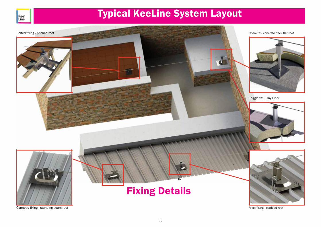
Typical KeeLine System Layout
Bolted fixing - pitched roof Chem fix - concrete deck flat roof
Toggle fix - Tray Liner
Fixing Details
Clamped fixing - standing seam roof Rivet fixing - cladded roof
6

KeeLine Components BS EN 795 Type C 160mm 95mm
80mm
425mm
425mm
45mm
STANDARD INTERMEDIATE BRACKET - Wall and Roof Mounted INTW010 Designed to allow the Traveller to pass over the brackets without detaching from the system. Maximum span of 15m between Intermediate Brackets. Material : Stainless steel AISI
316L. Breaking strength >12kN. Net weight : 0.49kg.
CORNER TUBE - Wall mounted 90º - CNR-90-W
Wall mounted 135º - CNR-135-W Allows the system to turn through 90º or 135º Other angles can be achieved via cutting the tube
in order to form the required angle. Material : Stainless steel AISI 316L. Ø 13.5mm.
Net weight : 0.2kg. (Tube only) Net Weight : 1.03kg. (Complete assembly)
440mm
45mm
95mm
80mm
Ø13mm
363mm
EXTENDED INTERMEDIATE BRACKET - Wall and Roof Mounted INTEW010 Designed to allow the Traveller to pass over the brackets without detaching from the system. Maximum span of 15m between Intermediate Brackets. Material : Stainless steel AISI
316L. Breaking strength >12kN. Net weight : 0.63kg.
60mm 80mm
100mm
160mm
160mm
STANDARD INTERMEDIATE BRACKET - Overhead - KOINT Designed to allow the Traveller to pass over the brackets without detaching from the system. Maximum span of 15m between Intermediate Brackets. Material : Stainless steel AISI
316L. Breaking strength >12kN. Net weight : 0.8kg.
CORNER BRACKET - Wall and Roof mounted 90º - LAKL20090 Allows the system to turn through 90º or 135º Other angles can be achieved via cutting the tube
in order to form the required angle. Material : Stainless steel AISI 316L. Ø 13.5mm.
Net weight : 0.46kg.
203mm
CORNER BRACKET - Wall and Roof mounted 45º - LAKL20045 Allows the system to turn through 90º or 135º Other angles can be achieved via cutting the tube
in order to form the required angle. Material : Stainless steel AISI 316L. Ø 13.5mm.
Net weight : 0.388kg.
7
KeeLine Components BS EN 795 Type C
400-510mm
25mm
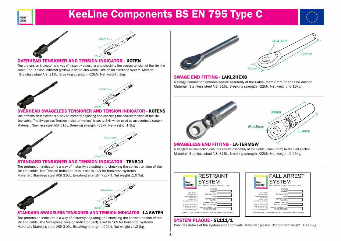
OVERHEAD TENSIONER AND TENSION INDICATOR - KOTEN The pretension indicator is a way of instantly adjusting and checking the correct tension of the life line
cable. The Tension Indicator (yellow) is set to 3kN when used on an overhead system. Material : Stainless steel AISI 316L. Breaking strength >22kN. Net weight : 1kg.
375-490mm
25mm
OVERHEAD SWAGELESS TENSIONER AND TENSION INDICATOR - KOTENS The pretension indicator is a way of instantly adjusting and checking the correct tension of the life
line cable. The Swageless Tension Indicator (yellow) is set to 3kN when used as an overhead system.
Material : Stainless steel AISI 316L. Breaking strength >22kN. Net weight : 1.3kg.
400-510mm
25mm
STANDARD TENSIONER AND TENSION INDICATOR - TENS10 The pretension indicator is a way of instantly adjusting and checking the correct tension of the
life line cable. The Tension Indicator (red) is set to 1kN for horizontal systems.
Material : Stainless steel AISI 316L. Breaking strength >22kN. Net weight :1.07kg.
375-490mm
25mm
STANDARD SWAGELESS TENSIONER AND TENSION INDICATOR - LA-SWTEN The pretension indicator is a way of instantly adjusting and checking the correct tension of the
life line cable. The Swageless Tension Indicator (red) is set to 1kN for horizontal systems.
Material : Stainless steel AISI 316L. Breaking strength >22kN. Net weight : 1.21kg.
Ø14.5mm
124mm
30mm
SWAGE END FITTING - LAKL2HEX8 A swage connection ensures secure assembly of the Cable (diam 8mm) to the End Anchor. Material : Stainless steel AISI 316L. Breaking strength >22kN. Net weight : 0.13kg.
98mm
Ø14.5mm 114mm
SWAGELESS END FITTING - LA-TERMSW A swageless connection ensures secure assembly of the Cable (diam 8mm) to the End Anchor. Material : Stainless steel AISI 316L. Breaking strength >22kN. Net weight : 0.26kg.
RESTRAINT FALL ARREST SYSTEM SYSTEM S E P A R A T I N G P E O P L E F R O M H A Z A R D S S E P A R A T I N G P E O P L E F R O M H A Z A R D S
SYSTEM SYSTEM
HEAD OFFICE
NUMBER
HEAD OFFICE
NUMBER
INSTALLATION
INSTALLATION
Kee Safety Limited Kee Safety Limited
Cradley Business Park DATE
Cradley Business Park DATE
Overend Road
MAX NUMBER Overend Road
MAX NUMBER
Cradley Heath Cradley Heath
West Midlands B64 7DW OF USERS
West Midlands B64 7DW OF USERS
LANYARD LENGTH
LANYARD LENGTH
(t) +44 (0) 1384 632 188 NOT TO EXCEED (t) +44 (0) 1384 632 188 NOT TO EXCEED
(f) +44 (0) 1384 632 192 ANNUAL INSPECTION
(f) +44 (0) 1384 632 192 ANNUAL INSPECTION
(e) [email protected] (e) [email protected]
(w) www.keesafety.co.uk RECOMMENDED (w) www.keesafety.co.uk RECOMMENDED
RE-TEST ONLY TO BE CARRIED OUT BY AUTHORISED SERVICE AGENT. RE-TEST ONLY TO BE CARRIED OUT BY AUTHORISED SERVICE AGENT.
SYSTEM PLAQUE - SL111/1 Provides details of the system and approvals. Material : plastic. Component weight : 0.085kg.
8
KeeLine Components BS EN 795 Type C
100mm
85mm
Ø14mm
200mm
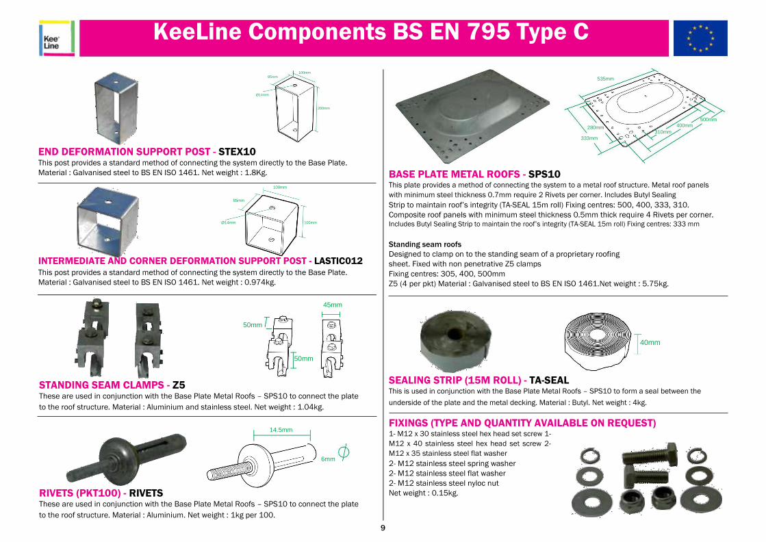
END DEFORMATION SUPPORT POST - STEX10 This post provides a standard method of connecting the system directly to the Base Plate. Material : Galvanised steel to BS EN ISO 1461. Net weight : 1.8Kg.
100mm
85mm
Ø14mm 100mm
INTERMEDIATE AND CORNER DEFORMATION SUPPORT POST - LASTIC012 This post provides a standard method of connecting the system directly to the Base Plate. Material : Galvanised steel to BS EN ISO 1461. Net weight : 0.974kg.
45mm
50mm
50mm
STANDING SEAM CLAMPS - Z5 These are used in conjunction with the Base Plate Metal Roofs – SPS10 to connect the plate
to the roof structure. Material : Aluminium and stainless steel. Net weight : 1.04kg.
14.5mm
6mm
RIVETS (PKT100) - RIVETS These are used in conjunction with the Base Plate Metal Roofs – SPS10 to connect the plate
to the roof structure. Material : Aluminium. Net weight : 1kg per 100.
535mm
500mm
280mm 400mm
310mm
333mm
BASE PLATE METAL ROOFS - SPS10 This plate provides a method of connecting the system to a metal roof structure. Metal roof panels
with minimum steel thickness 0.7mm require 2 Rivets per corner. Includes Butyl Sealing Strip to maintain roof’s integrity (TA-SEAL 15m roll) Fixing centres: 500, 400, 333, 310. Composite roof panels with minimum steel thickness 0.5mm thick require 4 Rivets per corner. Includes Butyl Sealing Strip to maintain the roof’s integrity (TA-SEAL 15m roll) Fixing centres: 333 mm
Standing seam roofs Designed to clamp on to the standing seam of a proprietary roofing
sheet. Fixed with non penetrative Z5 clamps
Fixing centres: 305, 400, 500mm Z5 (4 per pkt) Material : Galvanised steel to BS EN ISO 1461.Net weight : 5.75kg.
40mm
SEALING STRIP (15M ROLL) - TA-SEAL This is used in conjunction with the Base Plate Metal Roofs – SPS10 to form a seal between the
underside of the plate and the metal decking. Material : Butyl. Net weight : 4kg.
FIXINGS (TYPE AND QUANTITY AVAILABLE ON REQUEST) 1- M12 x 30 stainless steel hex head set screw 1-
M12 x 40 stainless steel hex head set screw 2-
M12 x 35 stainless steel flat washer 2- M12 stainless steel spring washer 2- M12 stainless steel flat washer 2- M12 stainless steel nyloc nut Net weight : 0.15kg.
9
KeeLine Components BS EN 795 Type C
80mm
75mm
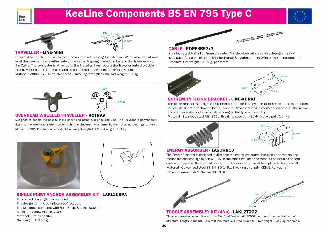
TRAVELLER - LINE-MINI Designed to enable the user to move easily and safely along the Life Line. When mounted at roof
level the user can move either side of the cable. A spring loaded pin fastens the Traveller on to
the Cable. The connector is attached to the Traveller, thus locking the Traveller onto the Cable.
The Traveller can be connected and disconnected at any point along the system.
Material : Z8CND17 04 Stainless steel. Breaking strength 12kN. Net weight : 0.3kg.
115mm
125mm
OVERHEAD WHEELED TRAVELLER - KOTRAV Designed to enable the user to move easily and safely along the Life Line. The Traveller is permanently
fitted to the overhead system cable. It is manufactured with brass bushes, thus no bearings to wear.
Material : Z8CND17 04 Stainless steel. Breaking strength 12kN. Net weight : 0.68kg.
SINGLE POINT ANCHOR ASSEMBLEY KIT - LAKL20SPA This provides a single anchor point. The design permits complete 360º rotation. The kit comes complete with Bolt, Bush, Sealing Washer, Label and Screw Plastic Cover. Material : Stainless Steel. Net weight : 0.176kg
CABLE - ROPE8SS7x7 Stainless steel AISI 316L 8mm diameter 7x7 structure with breaking strength > 37kN, is suitable for spans of up to 15m horizontal & overhead up to 24m between Intermediate Brackets. Net weight : 0.28kg. per metre.
80mm
60mm
250mm
EXTREMITY FIXING BRACKET - LINE-XBRKT The fixing bracket is designed to terminate the Life Line System at either end and is intended
to provide direct attachment for Tensioners, Absorbers and pretension indicators. Alternative
end components may be used, depending on the type of assembly.
Material : Stainless steel AISI 316L. Breaking strength >22kN. Net weight : 1.24kg.
265mm
85mm
110mm
ENERGY ABSORBER - LASORB10 The Energy Absorber is designed to dissipate the energy generated throughout the system and
reduce the end loadings to below 10kN. Installations require an absorber to be installed at both
ends of the system. The element is a disposable device which must be replaced after each fall. Material : Galvanised steel BS EN ISO 1461. Breaking strength >22kN. Activating
force minimum 2.9kN. Net weight : 3.6kg.
150mm
M10 thread 300mm long.
30mm
TOGGLE ASSEMBLEY KIT (4No) - LAKL2TOG2 These are used in conjunction with the Flat Roof Post – LAKL2POST to connect the post to the roof
structure. Length Standard 300mm Ø M8. Material : Steel Grade 8.8. Net weight : 0.258kg no thread. 10

KeeLine Components BS EN 795 Type C
301mm
275mm
415mm
335mm
195mm
STANDARD FLAT ROOF POST- LAKL2POST This post provides a standard method of connecting the system directly to the flat roof structure. The Flat Roof Post can be installed on top of the insulation and waterproof membrane via a
toggle or chemical fixing. Cowling for weather detail selected separately.
Material : Stainless Steel AISI. Net weight Post : 4.168kg.
120mm
14mm
135mm
STANDARD WEATHER COWLING - COATED - WC120 This Cowling provides the weatherproofing detail. Material : Galvanised steel to BS EN ISO 1461. Net weight Cowling : 1kg.
Ø78mm
257mm
Ø255mm
WEATHER COWLING - NON-COATED - LAKL20ALU This Cowling provides the weatherproofing detail supplied non-coated Material : Aluminium. Net weight : 0.396kg.
Ø78mm
257mm
Ø255mm
WEATHER COWLING - COATED - LAKL20PVC This Cowling provides the weatherproofing detail supplied pre-coated for
torchon single ply membranes
Material : Aluminium. Net weight : 0.494kg. 11
KeeLine Components BS EN 795 Type C
120mm
14mm
135mm
465mm
50mm
15mm
300mm 300mm
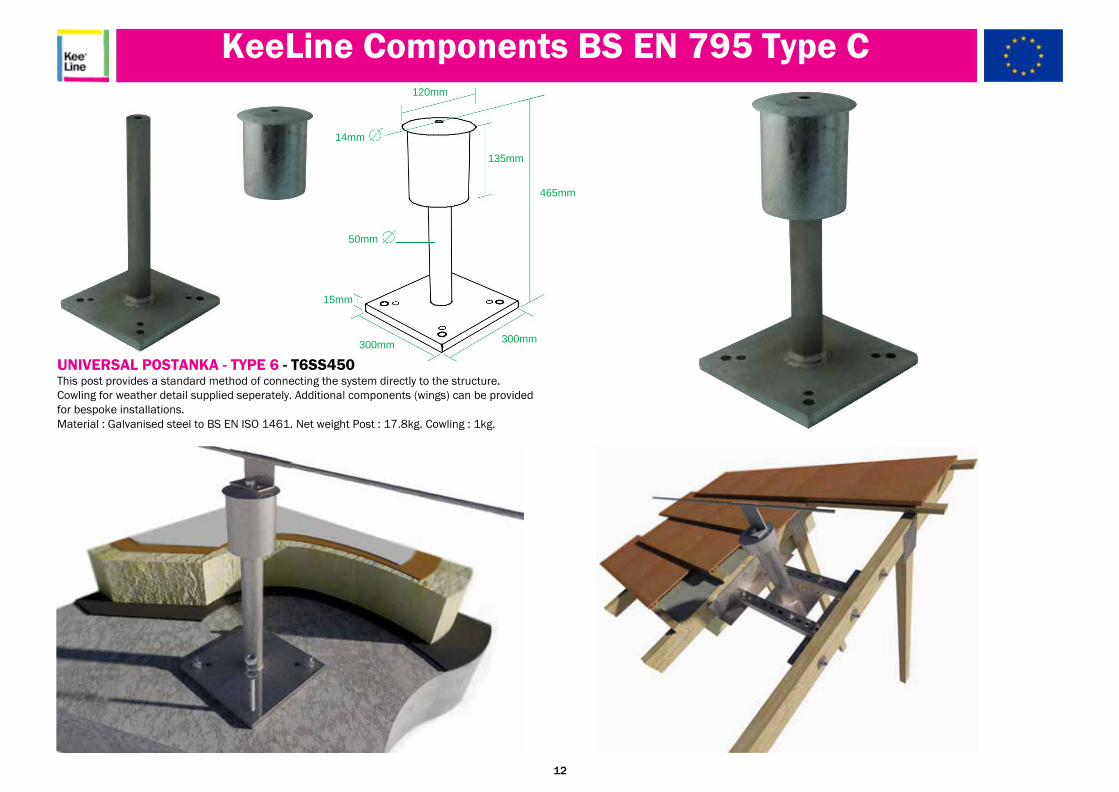
UNIVERSAL POSTANKA - TYPE 6 - T6SS450 This post provides a standard method of connecting the system directly to the structure. Cowling for weather detail supplied seperately. Additional components (wings) can be provided
for bespoke installations.
Material : Galvanised steel to BS EN ISO 1461. Net weight Post : 17.8kg. Cowling : 1kg.
12
KeeLine Components BS EN 795 Type C
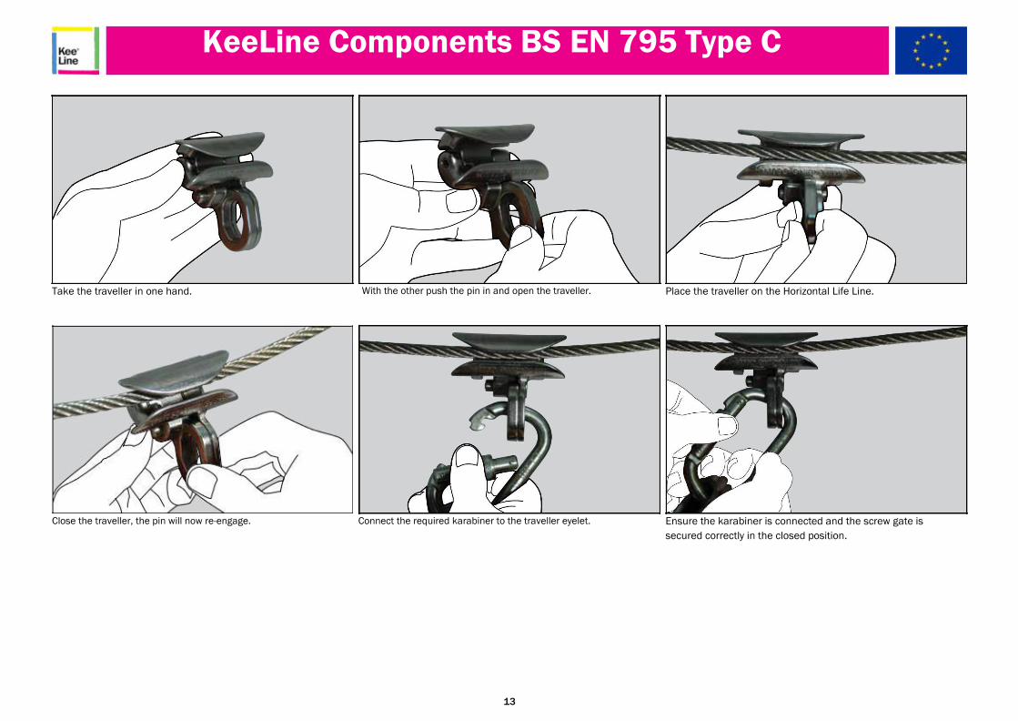
Take the traveller in one hand.
Close the traveller, the pin will now re-engage.
With the other push the pin in and open the traveller.
Connect the required karabiner to the traveller eyelet.
Place the traveller on the Horizontal Life Line.
Ensure the karabiner is connected and the screw gate is
secured correctly in the closed position.
13

Minimum Height Requirements
Diagram A Anchor point above user. (In this case 1m (3.28’) above user’s harness attachment
point) (Preferred Option)
Free fall distance: 0.5m (1.64’) Fall factor = 0.5/1.5 = 0.3 (1.64/4.92 = 0.3
Diagram B Anchor point at shoulder
level. (Non-preferred option)
Free fall distance: 1.5m (4.92’) Fall factor = 1.5/1.5 = 1.0 (4.92/4.92 = 1.0)
Diagram C Anchor point at foot
level. (To be avoided)
Free fall distance: 3.0m (9.84’) Fall factor = 3.0/1.5 = 2.0 (9.84/4.92 = 2.0)
NOTE: The lower human figure in each diagram indicates the position of the user at the end of
the free fall. This is the point at which the energy absorber begins to deploy and should not be
confused with the position the user would be in at the end of the arrest of the fall.
KEY F = Free fall distance
(Source BS 8437:2005)
The above diagram shows three fall arrest situations. In each case the fall arrest system is based on a 1.5m (4.92’) long energy absorbing lanyard and a distance between the attachment point on
the user’s harness and their feet of 1.5m (4’92”). The free fall distance is the vertical distance between the position of the user’s feet immediately before the fall, and the position of the user’s feet at
the point at which the lanyard has become taut and started to arrest the fall. (Figure F in the diagram)
14
Work at Height Rescue
Before commencing any work at height activity please ensure you are adequately trained and competent to carry out the task and able to use the safety equipment provided by your employer/building owner.
In situations where a work at height activity involves a “fall arrest” situation, it is a legal requirement for your employer/building owner to provide the anchorage point, rescue plan, policy, training and
equipment to complete a rescue. It is not the responsibility of the emergency services to conduct such a rescue.
Should a rescue become necessary it is extremely important that the procedures detailed in the “roof permit to work,” rescue policy and plan are followed. Try to make contact with the casualty to
establish if they are conscious or unconscious. If they are unconscious then time is of the essence.
Contact the emergency services and request an ambulance and fire/rescue support. Inform them of the exact address, location and site contact details of where you are working (This should be
contained within the “permit to work”). Confirm that you are trained and competent to commence the rescue procedure.
Call your site contact and inform them of the situation and that you have already contacted the emergency services. Request they bring a competent First Aider to assist you at ground level by
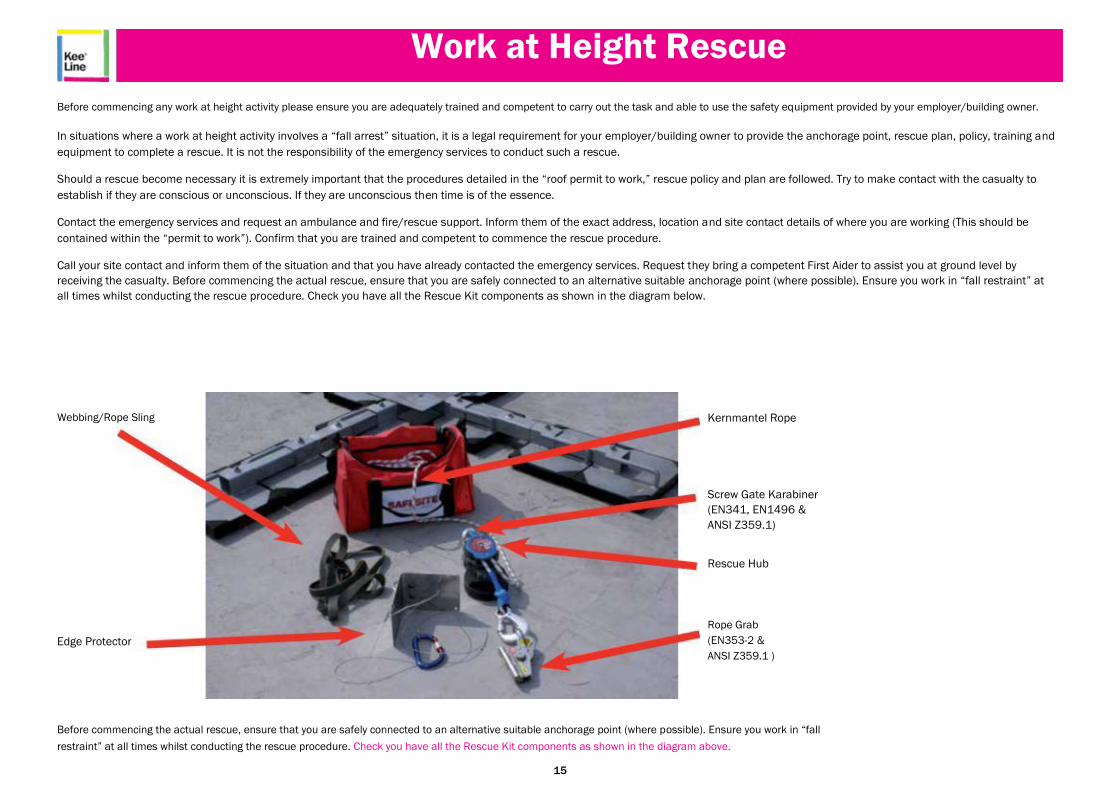
receiving the casualty. Before commencing the actual rescue, ensure that you are safely connected to an alternative suitable anchorage point (where possible). Ensure you work in “fall restraint” at
all times whilst conducting the rescue procedure. Check you have all the Rescue Kit components as shown in the diagram below.
Webbing/Rope Sling
Edge Protector
Kernmantel Rope
Screw Gate Karabiner
(EN341, EN1496 &
ANSI Z359.1)
Rescue Hub
Rope Grab
(EN353-2 &
ANSI Z359.1 )
Before commencing the actual rescue, ensure that you are safely connected to an alternative suitable anchorage point (where possible). Ensure you work in “fall
restraint” at all times whilst conducting the rescue procedure. Check you have all the Rescue Kit components as shown in the diagram above.
15

Rescue Kit Operation
a. Connecting to the same or an alternative suitable anchorage point. Connect the Rescue Hub device using the Screw b. Pull the end of the Kernmantel Rope which has the Rescue
Gate Karabiner fitted directly to the Rescue Hub. Ensure the Screw Gate is tightened once connected to the anchorage Rope Grab attached. The Kernmantel Rope will start to feed out
point. of the rescue bag and run through the Rescue Hub.
c. Start walking towards the area where the casualty has
fallen whilst still holding the Rescue Rope Grab. When you
reach this area, kneel down and continue to pull out sufficient
rope to reach the “D” ring on the casualty’s harness.
d. Ensure the Edge Protector is connected to the anchorage point, this may need to be extended in some cases via a webbing
or rope sling. Place the Edge Protector over the edge ready for the rescue operation.
16
Rescue Kit Operation
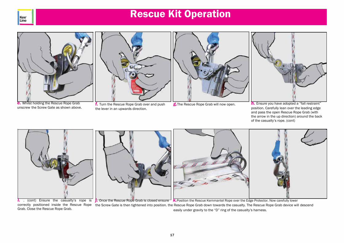
e. Whilst holding the Rescue Rope Grab
unscrew the Screw Gate as shown above.
f. Turn the Rescue Rope Grab over and push g.The Rescue Rope Grab will now open.
the lever in an upwards direction.
h. Ensure you have adopted a “fall restraint” position. Carefully lean over the leading edge
and pass the open Rescue Rope Grab (with
the arrow in the up direction) around the back
of the casualty’s rope. (cont)
i. . (cont) Ensure the casualty’s rope is
correctly positioned inside the Rescue Rope Grab. Close the Rescue Rope Grab.
j. Once the Rescue Rope Grab is closed ensure k.Position the Rescue Kernmantel Rope over the Edge Protector. Now carefully lower the Screw Gate is then tightened into position. the Rescue Rope Grab down towards the casualty. The Rescue Rope Grab device will descend
easily under gravity to the “D” ring of the casualty’s harness.
17

Rescue Kit Operation
l. Return to the anchorage point where the Rescue Hub is connected. Pull any excess Kernmantel Rope through the Rescue Hub by pulling the free end of the rope which
is stored in the bag.
o. With the black handle in position push in the silver ball bearing positioned in the centre of the white plate as shown above.
m. Once the Rescue Hub Kernmantel Rope is taught, rotate & lower the locking pin so that it engages with the body of the hub. When in place correctly, the hub cannot turn.
p. Now open the top third of the Rescue Hub and it
will automatically lock into place.
n. Lift up the black handle as shown above.
q. Detach the pin.
18

Rescue Kit Operation
r. Start winding the Rescue Hub in a clockwise direction so that the Kernmantel Rope passes through the hub. If the rope
does not move through the hub, pull on the free end of the
rope. Continue to wind until the casualty’s primary rope
becomes slack.
t. You can now remove the casualty’s slack primary rope
from the anchorage point as shown above.
s. Once the casualty’s primary rope is slack enough to detach their primary hook/karabiner from the anchorage point,
stop winding and engage the locking pin by lifting, rotating & then lowering it. Ensure the pin is engaged against the body of the Rescue Hub. When in place correctly the Hub cannot turn.
u. Close the Rescue Hub by pressing in the silver ball bearing in the centre of the white plate. Once closed fold down
the plastic handle.
19
Rescue Kit Operation
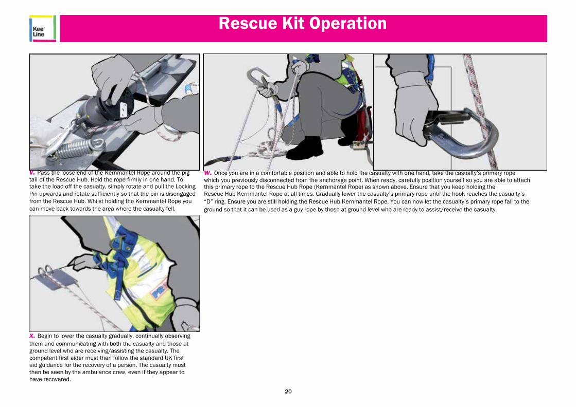
v. Pass the loose end of the Kernmantel Rope around the pig
tail of the Rescue Hub. Hold the rope firmly in one hand. To take the load off the casualty, simply rotate and pull the Locking
Pin upwards and rotate sufficiently so that the pin is disengaged
from the Rescue Hub. Whilst holding the Kernmantel Rope you
can move back towards the area where the casualty fell.
x. Begin to lower the casualty gradually, continually observing them and communicating with both the casualty and those at
ground level who are receiving/assisting the casualty. The
competent first aider must then follow the standard UK first
aid guidance for the recovery of a person. The casualty must
then be seen by the ambulance crew, even if they appear to
have recovered.
w. Once you are in a comfortable position and able to hold the casualty with one hand, take the casualty’s primary rope
which you previously disconnected from the anchorage point. When ready, carefully position yourself so you are able to attach this primary rope to the Rescue Hub Rope (Kernmantel Rope) as shown above. Ensure that you keep holding the Rescue Hub Kernmantel Rope at all times. Gradually lower the casualty’s primary rope until the hook reaches the casualty’s
“D” ring. Ensure you are still holding the Rescue Hub Kernmantel Rope. You can now let the casualty’s primary rope fall to the
ground so that it can be used as a guy rope by those at ground level who are ready to assist/receive the casualty.
20
KeeLine Recertification
• Periodic inspections by a competent person are recommended by the manufacturer and required under Regulation 5 of the Workplace (Health Safety & Welfare)
Regulations, BS EN 365 & BS 7883. The frequency will depend upon environment, location and usage, but should be at least every 12 months.
• Check structural connection of system.
• Walk the complete system and check the smooth running over all intermediate brackets and that the system still serves client’s needs.
• Establish if any modifications or additional products are required to reflect any refurbishment or additional plant and equipment that has been installed and requires access.
• Inspect shock absorber.
• Inspect cable for damage / kinks / signs of wear.
• Check and tighten all visible / accessible fixings.
• Any galvanised components showing signs of corrosion, wire brush thoroughly and apply galvanised spray / paint as appropriate.
• If rusted significantly take digital photographs and include in inspection report.
• Pull test visible end fixings to concrete / brickwork / structure (where possible) 6kN - 15 secs.
• Re-tension cable if required to allow smooth operation of the system (where required).
• Clean entire cable run with white spirit.
• Any part of the installation or fixings that may need additional attention including shock absorber - take digital photographs and include in the inspection report.
• Any major components, other than nuts/ bolts/ washers etc, which may need replacing report to client and establish costings, so that if possible it can be repaired whilst on site.
• Check system plaque position & mark up to reflect date of the next required inspection. Establish if additional plaques are required due to any refurbishment work.
21

Kee
Line