kcs - saab defence and security – multi-functional sensor network management kcs –...
TRANSCRIPT

KCS MULTI-FUNCTIONAL SENSOR NETWORK MANAGEMENT
KCS – MULTI-FUNCTIONAL SENSOR NETWORK MANAGEMENT
© by Saab Medav Technologies GmbH – Specification subject to change – Page 2/16
KCS KEY FEATURES The KCS is a solution for the organisation, configuration, and monitoring of sensors. It embeds sensors for the detection, identification, classification and localisation of radio emitters of interest depending on the scenario.
Different sensor types can be connected to the KCS: Direction finders, TDoA (time difference of arrival), radio monitors and transponders (e.g. on ships, airplanes). Additionally, third-party (external) sensors can be integrated into the KCS. One focus of this network is on intuitive usage and handling. It also includes support for logistic functions, e.g. procedures for the deployment and de-installation of mobile sensors. Automated updates and failure management are especially useful for unmanned sensors.
At the sensors, a large number of emissions are detected and processed. The KCS compresses the information for tactical purposes using the sensor results and sensor cross-cueing leading to situational awareness at the central station.
The KCS is a vital part of the Saab Medav Technologies Smart SIGINT approach.
KEY FEATURES
Ability to incorporate numerous and heterogeneous sensors and sensor networks
Classification, identification, warning function
Automated control of remote sensors
Fast adaption of large sensor networks to new situations, including multi-functional sensors
Cueing of sensors
Configurable data link communication between sites
Real-time map display
Advanced and dynamic resource management.
Logistics support, procedures for deployment and de-installation of mobile sensors.
Reliable fault management system for sensor networks.
Simulation and training function available
Intuitive usage
SCENARIOS FOR KCS
Border and coastal surveillance
Surveillance from the air
Convoy protection
Scheduled surveillance for radio reconnaissance
Mobile emitter detection in urban scenarios
The KCS is a digitally controlled sensor management solution not designed for use with civil cellular radio-communications systems. Relevant export control regulations are considered according to 5A001.b.5 of the REGULATION (EU) No 1382/2014 OF THE EUROPEAN PARLIAMENT AND OF THE COUNCIL. Optional special demodulators are subject to EU and German export law.

KCS – MULTI-FUNCTIONAL SENSOR NETWORK MANAGEMENT
© by Saab Medav Technologies GmbH – Specification subject to change – Page 3/16
IMPRESSIONS
BENEFITS
FOR THE ORGANISATION
Significantly improves Electronic Support Measures (ESM)
Single system control and organisation of all sensor systems
Complete surveillance coverage including HF / VUHF / SHF bands
Automated processing of emissions of interest
Generation of signal reports for further detailed analysis
Collection of knowledge of radio emitters and radio scenarios
Support for mission specific radio theatres with a priori knowledge
FOR THE OPERATOR
Intuitive user-interface, also suitable for non-expert operators in remote locations.
Clear and thorough guidelines for installation, update and transport of remote stations
Sophisticated tools for detailed signal analysis
Signal data base
REFERENCES The KCS was introduced to the market in 2010. Since then it has been installed in several customer projects, above all for the management of sensors in extensive applications. Various sensor types have been integrated. The KCS also serves as a basis for Saab Medav Technologies information fusion system IFS-8000.

KCS – MULTI-FUNCTIONAL SENSOR NETWORK MANAGEMENT
© by Saab Medav Technologies GmbH – Specification subject to change – Page 4/16
KCS SYSTEM OVERVIEW
SYSTEM ARCHITECTURE (PAGE 6) The KCS is a sensor network solution which organizes and incorporates numerous sites and sensors. The architecture of the KCS is flexible and can be quickly changed to adapt to new situations. Basis of the architecture is the central station, where the supervisors and operators control missions at the remote sites. Sensors can be grouped according to tasks or geographical conditions and are assigned to a site. The assignment can be updated according to new tasks and missions.
A site can be either static (e.g. tower installation) or mobile (e.g. vehicle installation).
The software at all stations and sites is identical. The extent of software access will vary depending on defined user roles and rights.
During the configuration of the KCS, the required user roles and their rights are defined. Depending on the available data link between the central station and the remote sites, data transfer can be adapted accordingly.
SENSOR TYPES & SENSOR GROUPS (PAGE 7)
Different types of sensors can be used with the KCS. Typical sensor types are direction finding, TDoA geo-localisation and radio monitoring. Transponder sensors can be used as well as external third-party sensors. For some applications, like direction finding, sensors are grouped across different sites. The sensors of a group can thus be accessed to fulfil the task in the same manner as if they were at the same site.
SITE CONFIGURATION (PAGE 8)
All sites, manned or unmanned, can be configured from the central station. Data can be entered intuitively for an entire site. Configuration can also be done for single sensors as well as for complete sensor groups. Sensors can be assigned to a certain sensor group. The assignment can be changed dynamically for new missions and tasks.
MISSIONS AND TASKS (PAGE 9)
The work in KCS is organized into missions and tasks. Missions are planned and configured at the central station. A mission involves one sensor group. During a mission, several tasks can be performed. The control of missions is usually performed at the central station as well. Mission setups can be stored for later use.
DATA BASES (PAGE 9)
Data bases provide collected knowledge. They support the set-up of missions and the identification of emitters from different sensors and sensor groups in the same manner (unified data modelling).
The frequency data base (FDB) describes well-known frequency entries and allows the grouping of frequency entries. The target data base (TDB) describes well-known targets and enables the grouping of targets. New knowledge can be added to the data base.

KCS – MULTI-FUNCTIONAL SENSOR NETWORK MANAGEMENT
© by Saab Medav Technologies GmbH – Specification subject to change – Page 5/16
REAL-TIME MAP DISPLAY (PAGE 10)
The main goal of the operators in KCS is to identify and track emitters. These results can be best displayed with real-time map viewers. With these, all mapping operations like zooming, panning etc. are possible. Additionally, maps can be used for measuring and mission planning.
SYSTEM MONITORING (PAGE 12)
The system monitoring functions of the KCS are an important feature providing for easy and reliable handling. Monitoring an elaborate system with numerous sensors, sensor groups, sites, and missions can be performed intuitively.
The status of all components and findings can be displayed including additional information and proposals for the handling of system errors and warnings.
MAINTENANCE AND LOGISTICS SUPPORT (PAGE 13)
Especially for unmanned sites, the KCS offers automated maintenance support – software updates can be performed automatically according to the sensor or site type if decided by the central station.
For mobile and semi-mobile sensors, a detailed interactive installation procedure guide is provided for the installation of sensors even by untrained personnel.
TRAINING AND SIMULATION (PAGE 14) - OPTION
The role concept of the KCS allows fora trainer-trainee application. Special missions can be simulated by the trainer with realistic scenarios. Trainees can then plan and perform missions in the simulation mode. Both target and sensor simulations are possible.
OFFLINE PROCESSING & SIGNAL ANALYSIS (PAGE 14) - OPTION
Both wideband and narrowband signal analysis can be performed. The operator at the central station is able to log on to the sensor and perform signal analysis there.
In case the transmission bandwidth between the central station and sensors is too small for the transmission of all data, it can be stored and transmitted at a later stage.

KCS – MULTI-FUNCTIONAL SENSOR NETWORK MANAGEMENT
© by Saab Medav Technologies GmbH – Specification subject to change – Page 6/16
ARCHITECTURE The KCS solution consists of a central station and a set of remote sites containing sensors. Depending on the available communication bandwidth, the central station is connected to the remote stations via different communication types ranging from WLAN to GPRS (s. page 15).
CENTRAL STATION
In one system, there is generally only one central station. For failover reasons, additional central stations may be realized. The main functions are:
System management
Overview of all sites and sensors
Functionality to re-group and re-configure sensors on the fly
Planning and implementation of complex missions and tasks
Advanced target identification
Resource and fault management
Remote update and maintenance of sensors and data bases
REMOTE SITES
A KCS solution can contain a variable number of sites. The sites can be configured to work in a manned/unmanned or mobile/stationary manner. Every site can contain several sensors or sensor groups. One site can be connected to one central station at a time. For failover reasons, a site assignment can be changed to another central station.
The main functions at the sites are:
Autonomous operation
Compression and storage of results and signals
SOFTWARE & ROLE MODELS
All sites use the same KCS software.
User interfaces provide
Different client defined functionalities at different sites
Different role models – roles are defined based on application requirements. Typical roles are
o Supervisor: mission/task planning (central station)
o Operator: sensor station movement, on-site mission control when required
o Administrator: system upgrading, updating and maintenance
For training and simulation additional roles like trainer and trainee are possible.
The various rights and roles can be configured freely and intuitively.
KCS – MULTI-FUNCTIONAL SENSOR NETWORK MANAGEMENT
© by Saab Medav Technologies GmbH – Specification subject to change – Page 7/16
SENSOR TYPES & SENSOR GROUPS The available sensors in the KCS are categorized according to their functionality. Currently, the following types of sensors have been put into practice:
Monitoring sensor: This sensor recognizes and classifies wideband and narrowband radio signals in the HF/VUHF/SHF frequency band. The analysis of the wideband and narrowband signals is performed by the sensors themselves. Saab Medav Technologies products ARS-8000 and MARIE can be used as such sensors.
DF sensor: Direction finding sensors are used for determining the direction of an emitter. In a DF sensor, the respective direction finders are included (e.g. 5-channel-DF) together with the required hardware and software. If two DF sensors are assigned to the same group, geo-localisation can be performed. Saab Medav Technologies products in this sensor category are CRS-8000 and MDF.
TDoA sensor: This sensor type is used for geo-localisation applying the TDoA (time difference of arrival) principle. For this special type of geo-localisation, at least three TDoA sensors are necessary.
Transponder sensor: This sensor type provides transponder information containing typical parameters and geo-localisation information of e.g. ships.
External sensor: Other third-party sensor types can also be embedded into the KCS providing different functionality.
Findings from these sensor types are stored in the sensor data base and can be viewed in the KCS.
The KCS follows the principle of multifunctional sensor management i.e. the same hardware can be used for different applications so that only the software has to be reconfigured. This is made possible through the use e of SDIA® (Software Defined Intelligence Architecture).
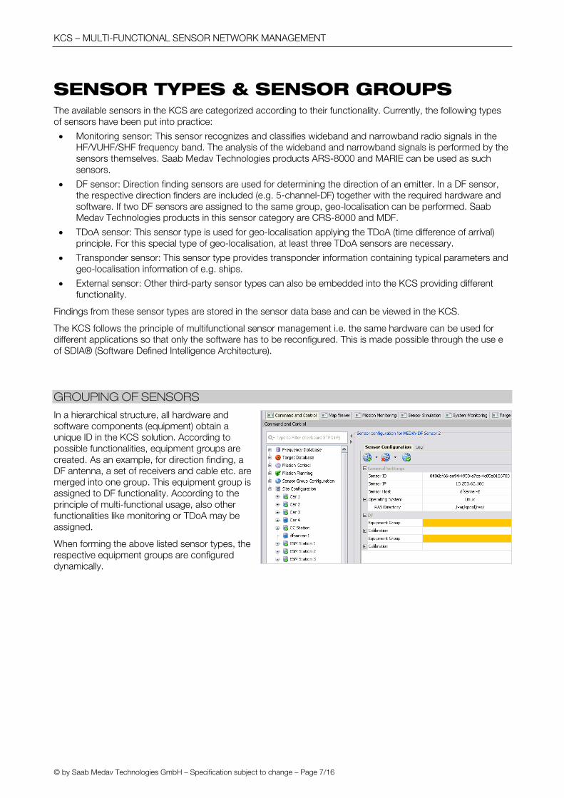
GROUPING OF SENSORS
In a hierarchical structure, all hardware and software components (equipment) obtain a unique ID in the KCS solution. According to possible functionalities, equipment groups are created. As an example, for direction finding, a DF antenna, a set of receivers and cable etc. are merged into one group. This equipment group is assigned to DF functionality. According to the principle of multi-functional usage, also other functionalities like monitoring or TDoA may be assigned.
When forming the above listed sensor types, the respective equipment groups are configured dynamically.
KCS – MULTI-FUNCTIONAL SENSOR NETWORK MANAGEMENT
© by Saab Medav Technologies GmbH – Specification subject to change – Page 8/16
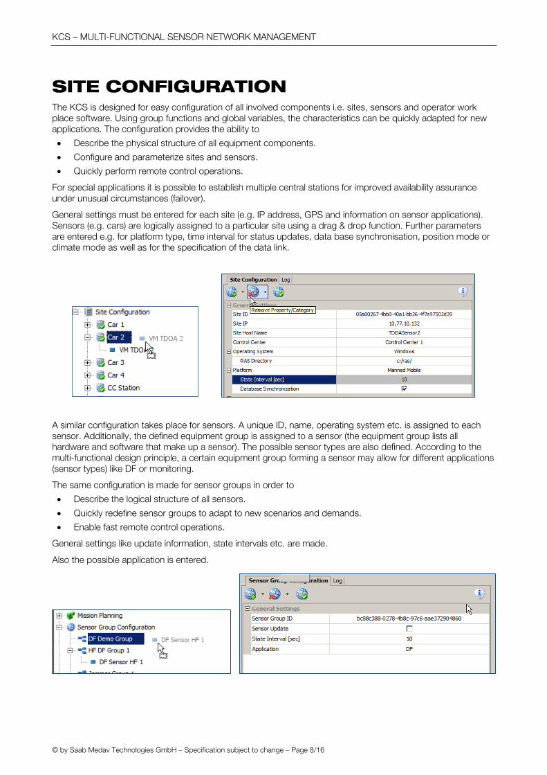
SITE CONFIGURATION The KCS is designed for easy configuration of all involved components i.e. sites, sensors and operator work place software. Using group functions and global variables, the characteristics can be quickly adapted for new applications. The configuration provides the ability to
Describe the physical structure of all equipment components.
Configure and parameterize sites and sensors.
Quickly perform remote control operations.
For special applications it is possible to establish multiple central stations for improved availability assurance under unusual circumstances (failover).
General settings must be entered for each site (e.g. IP address, GPS and information on sensor applications). Sensors (e.g. cars) are logically assigned to a particular site using a drag & drop function. Further parameters are entered e.g. for platform type, time interval for status updates, data base synchronisation, position mode or climate mode as well as for the specification of the data link.
A similar configuration takes place for sensors. A unique ID, name, operating system etc. is assigned to each sensor. Additionally, the defined equipment group is assigned to a sensor (the equipment group lists all hardware and software that make up a sensor). The possible sensor types are also defined. According to the multi-functional design principle, a certain equipment group forming a sensor may allow for different applications (sensor types) like DF or monitoring.
The same configuration is made for sensor groups in order to
Describe the logical structure of all sensors.
Quickly redefine sensor groups to adapt to new scenarios and demands.
Enable fast remote control operations.
General settings like update information, state intervals etc. are made.
Also the possible application is entered.

KCS – MULTI-FUNCTIONAL SENSOR NETWORK MANAGEMENT
© by Saab Medav Technologies GmbH – Specification subject to change – Page 9/16
MISSIONS AND TASKS Work with the KCS is based on missions and tasks. A sensor group can work on one mission at a time, but it can process several tasks at the same time. Two types of missions are available:
Planned mission: all mission parameters are specified before you run the mission. You can subdivide your mission into different tasks and determine what exactly is to be observed and how the observations are to be processed.
Ad-hoc mission: is a quick way to focus on observations without previous planning
The steps to prepare a planned mission are:
Collect information about the scenario, i.e. specify and analyse the location
Collect information about the target and specify the targets (e.g. frequency range, bandwidth, number of channels, other radio characteristics)
Specify the time and duration of your mission
Enter a priori knowledge into the data base if available.
Set up the connection between the central station and remote stations, sensors and transport vehicles
Ad-hoc missions do not need planning before they can be run. The only parameters needed are the frequency range and the sensor selection on which they are to be run. This allows operators to react quickly to current radio events in their scenario.
During a mission, several tasks can be performed, e.g. tracking, filtering according to frequency, location, waveform etc., recording and reporting.
DATA BASES For the planning of missions, mainly two data bases in the central station are used:
Frequency data base (FDB): description of well-known frequency entries, grouping of frequency entries
Target data base (TDB): description of well-known targets, grouping of targets.

KCS – MULTI-FUNCTIONAL SENSOR NETWORK MANAGEMENT
© by Saab Medav Technologies GmbH – Specification subject to change – Page 10/16
REAL-TIME MAP DISPLAY Every workplace and role has the possibility to use a map display. The two primary uses of the map display are as follows:
To visualize emitters, sensors and important objects on a map
As central user interface for working with the KCS, i.e., to control search for emissions, tracking and tasking new sensors. In this mode, the maps can be used for measuring and also for mission planning.
In most cases the operator’s objective will be to identify and track the movements of their observation targets. They see the results while running a mission as well as afterwards (replay function) on a map viewer. It displays the target area using different types of maps (topographic, satellite, etc. also customer defined maps).
The information on emitters and other previously defined objects are displayed at their position in different layers. Using the layer function, objects of the same type can be faded in and out of the map.
KCS – MULTI-FUNCTIONAL SENSOR NETWORK MANAGEMENT
© by Saab Medav Technologies GmbH – Specification subject to change – Page 11/16
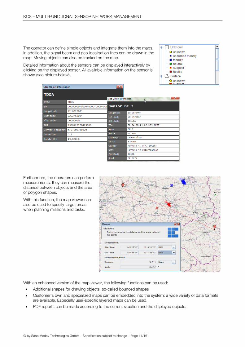
The operator can define simple objects and integrate them into the maps. In addition, the signal beam and geo-localisation lines can be drawn in the map. Moving objects can also be tracked on the map.
Detailed information about the sensors can be displayed interactively by clicking on the displayed sensor. All available information on the sensor is shown (see picture below).
Furthermore, the operators can perform measurements: they can measure the distance between objects and the area of polygon shapes.
With this function, the map viewer can also be used to specify target areas when planning missions and tasks.
With an enhanced version of the map viewer, the following functions can be used:
Additional shapes for drawing objects, so-called bounced shapes
Customer’s own and specialized maps can be embedded into the system: a wide variety of data formats are available. Especially user-specific layered maps can be used.
PDF reports can be made according to the current situation and the displayed objects.

KCS – MULTI-FUNCTIONAL SENSOR NETWORK MANAGEMENT
© by Saab Medav Technologies GmbH – Specification subject to change – Page 12/16
SYSTEM MONITORING At every point in time, system monitoring is possible. The so called BITE function (Built-In Test Equipment) allows the administrators to see the functionality and possible mal-functions.
All relevant information about the system is displayed visually in different colours to allow the administrators to see the status at a glance.
With the KCS three different types of system monitoring can be distinguished:
Sensor group monitoring
Site monitoring
Mission monitoring
Usually, there is no need to access the sites directly. All receiver adjustment, receiving, processing and information transmission to the central station is done automatically. Administrators and operators can contact any remote station and read off messages and the status of the sites.
For mission monitoring, the operators can access this database, inspect the reports and add additional information.
The result database contains all the messages the sensors issued during the mission. They can be accessed during a mission or afterwards. From information stored in the result databases, a mission can later be re-run for detailed inspection, fault analysis, mission documentation and operator training.
The database contains information on the measured values of the mission such as the SNR of an emission, the quality, error information and position or direction, etc. If the operator clicks on the position information in the table, he is promptly directed to the map viewer where the object is placed at its position for closer inspection.
Smart functions enable operators to organize the display so that they can focus on information that is relevant in their current situation. The table entries can be filtered, e.g. to fade out error messages when they are irrelevant or, vice-versa, show only the error entries to focus on the errors, depending on the intention of the operator at that moment. Also columns with unnecessary information can be faded out and the table can be sorted by column content.

KCS – MULTI-FUNCTIONAL SENSOR NETWORK MANAGEMENT
© by Saab Medav Technologies GmbH – Specification subject to change – Page 13/16
MAINTENANCE AND LOGISTICS SUPPORT Since the KCS is an elaborate and geographically distributed system, having reliable systems for maintenance and logistics support is vital.
MAINTENANCE
KCS maintenance is performed at the central station for all sites and sensors. The fact that maintenance tasks can be performed remotely and, where possible, in an automated manner, is a big advantage - especially when qualified personnel are not available at the sites. All components of the KCS can be maintained and updated automatically or manually depending on the chosen configuration. The following types are distinguished:
Data base maintenance
System maintenance
Remote update and maintenance of sensors
LOGISTICS SUPPORT
All components of the KCS, from large antennas to cables, are entered into the KCS configuration. All components are listed in the equipment section of the KCS configuration together with their status, position and other characteristics. That means e.g. every cable can be monitored as to where it is and to which equipment group, and further, to which sensor and sensor group, it is assigned.
The logistics support function is a very useful feature which describes every necessary part for the functioning of each application and provides detailed installation procedures. It contains:
The unique ID of an equipment component
The desired and current position
Installation procedure guide
The latter is especially helpful for untrained personnel in setting up mobile sensor applications. In this guide, an exact description of which component has to be installed and be connected with other components is provided. The guide is available for both the mounting and also the removal of remote sensors for all possible applications.
TRAINING & SIMULATION - OPTION The KCS offers an option for the education and training of operators and administrators. The role concept can be extended to trainer / trainee roles. In this mode, the trainer simulates a set of targets under realistic conditions and missions can be defined for operators. The trainee obtains this simulated scenario and can work in KCS as if in a real-scenario, using the complete KCS portfolio - depending on his role:
Configure KCS central and remote stations
Define missions and tasks
Perform missions
Perform administrative tasks
Using the modern technology of special emitter characteristics, the KCS is able to simulate a real-life scenario that could not be trained in the real world under normal circumstances.

KCS – MULTI-FUNCTIONAL SENSOR NETWORK MANAGEMENT
© by Saab Medav Technologies GmbH – Specification subject to change – Page 14/16
OFFLINE PROCESSING & SIGNAL ANALYSIS - OPTION Detailed offline processing and signal analysis of the detected emissions can be viewed using the processing results from the sensors. Depending on the available data communication link, the offline analysis can be performed at the sensors via remote control from the control station or directly at the sensors.
Detailed information about the possible analysis features can be found in the data sheets of the respective sensor systems (e.g. ARS-8000, MARIE, CRS-8000, OC-6040).
TECHNICAL DATA
COMMUNICATION TYPES - BETWEEN THE CENTRAL STATION AND REMOTE STATIONS
Type of data communication
Uplink data rate
Functions possible with the indicated data rate
GPRS 26.8 kbps Mission control, sensor monitoring, BITE
EDGE 108.8 kbps Mission control, sensor monitoring, BITE, 1 TDoA location finding per second (15 kHz signal with 200 msec duration)
UMTS 384.0 kbps Mission control, sensor monitoring, spectrum display and listen-in functionality, 2 TDoA location findings per second (15 kHz signal with 200 msec duration)
WLAN/LAN > 54 Mbps Mission control, sensor monitoring, spectrum display and listen-in functionality, > 100 TDoA location findings per second (15 kHz signal with 200 msec duration)
The described functions may be reduced depending on special configurations or distorted data links.

KCS – MULTI-FUNCTIONAL SENSOR NETWORK MANAGEMENT
© by Saab Medav Technologies GmbH – Specification subject to change – Page 15/16
SYSTEM CONFIGURATION The KCS consists of configurable software licenses. The flexible configuration of the system software enables the embedding of sensors, processors and workplace hardware.
Hardware is necessary for the sensors (antennas plus tuners), for the processing of tasks (processing units) and in the form of PCs for the workplaces.
The sensors consist of Saab Medav Technologies products for monitoring, direction finding or TDoA sensor. In addition, external sensors (e.g. transponders) can be included in the KCS solution.
The heart of the KCS solution is the central station with the Central Station SW. For every site, additional software must be added. For specific applications like TDoA and map display, additional licenses are required. For each sensor or sensor group to be embedded in the KCS solution, a license is necessary. For each work place, a Client Software license is required.
EXAMPLE CONFIGURATION – HYBRID GEO-LOCALISATION
KCS is used as a hybrid approach for monitoring, direction finding and geo-localisation with both TDoA and DF sensors.
The heart of this configuration is the central station with workplaces for two people. 4 sites (one manned and three unmanned sites) with different functionalities for monitoring, direction finding and sensors for TDoA applications. Geo-localisation is done with the hybrid approach using two TDoA sensors and one DF sensor.
Central station
1 KCS Central Station SW
1 KCS Central Station SW Localisation
2 KCS Client SW
2 KCS Client SW Map
1 KCS Client SW Map Extension
1 KCS Sensor SW Transponder
Site 1
1 KCS Client SW
1 KCS Sensor SW DF
1 KCS Sensor SW TDOA
Site 2 1 KCS Sensor SW TDOA
Site 3 1 KCS Sensor SW Monitoring
Site 4 1 KCS Sensor SW DF
For new tasks and upgrades, more sites and sensors can be added and configured easily.

Saab Medav Technologies GmbH Gräfenberger Str. 32-34, 91080 Uttenreuth, Germany Homburger Platz 3, 98693 Ilmenau, Germany Phone +49 9131 583-0 Fax: +49 9131 583-11 www.saab.com www.medav.de P
rodu
ct s
heet
–K
CS
- w
715o
d.1e
9 V
2.0