jürgen schilder/thorsten reibel sto/gm – abb customer ... · closing of roof windows after...
TRANSCRIPT

place picture here
Jürgen Schilder/Thorsten Reibel STO/GM – ABB Customer Training Center Heidelberg
ABB STOTZ-KONTAKT GmbHABB i-bus® KNXWebinar “Shutter Control with KNX”

Webinar “Shutter Control with KNX”Agenda
Introduction and Applications for Shutter Control
ABB i-bus KNX Shutter Actuators
ETS parameter
Automatic control
Sun protection (standard)
Sun protection with tracking of the sun’s position
Heating/cooling automatic
Redirection of daylight
SMI technology and actuators
Shutter actuators in function with ABB i-bus® Tool
© ABB17.09.2015 DESTO Jürgen Schilder | 2

© ABB9/17/2015 DESTO Jürgen Schilder | 3
Webinar “Shutter Control with KNX”Introduction
The Blind/Roller Shutter Actuators JRA/S facilitate complex demands on modern sun protection and ventilation control systems, without sacrificing comfort, cost-effectiveness and safety

© ABB9/17/2015 DESTO Jürgen Schilder | 4
Webinar “Shutter Control with KNX”Current situation
PresenceDetector
Room Controller 8.2
Room Master 2.1
Room Master 3.1
Room Controller 4.2
Shutter Actuator Module
230V
Shutter Actuator Module24V DC
Shutter Actuator SMI LoVo / 230V
Shutter Actuator230V
ShutterActuator24V DC
Outside Lightsensor
FM Blind Actuator
WeatherSensor
Radio Time
Switch
ShutterControl
Unit Switch Sensor

© ABB9/17/2015 DESTO Jürgen Schilder | 5
Webinar “Shutter Control with KNX”General
Modern building installation enables a high degree of functionality and simultaneously complies with increased security requirements
Due to the structured installation of the electrical components, it is possible to carry out rapid planning, installation and commissioning as well as achieve cost benefits during operation
Modern sun protection devices have a significant role, as they must fulfill many demands: Anti-glare protection (e.g. PC workstations) Utilization of daylight by tracking the sun‘s position and directing
available daylight Protecting furniture and carpets from fading, Regulating the room temperature (overheating protection in
summer; harvesting the available energy on cold days) Providing protection from people looking in from the outside Protection against intruders

© ABB9/17/2015 DESTO Jürgen Schilder | 6
Webinar “Shutter Control with KNX”General
The role of protection against the sun in buildings is increasing in significance due to increasing energy costs and statutory regulations
With intelligent and automated control via ABB i-bus® KNX, the Blind/Roller Shutter Actuators JRA/S play a significant role in the energy efficiency of all kinds of buildings
The potential savings for cooling using automatic blind control were presented in a study by the Biberach University of Applied Sciences

Webinar “Shutter Control with KNX”Shutters (roller shutter): Up/down – stop
Picture source: Internet
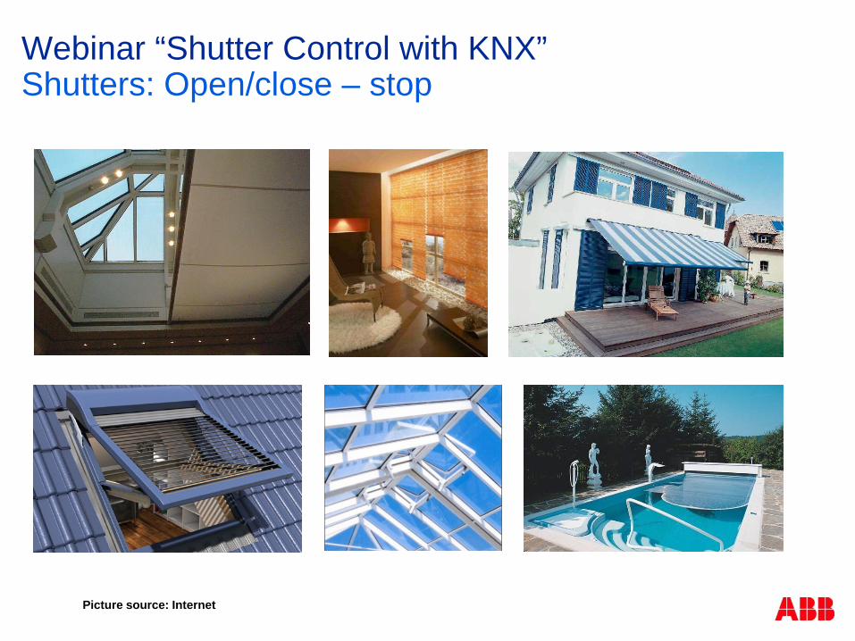
Webinar “Shutter Control with KNX”Shutters: Open/close – stop
Picture source: Internet

Webinar “Shutter Control with KNX”Blinds up/down – step(open and close)/stop
Curtain with vertical lamellas (vertical louvre blinds)
Curtain with horizontal lamellas (external venetian blinds)
Picture source: Internet

© ABB9/17/2015 DESTO Jürgen Schilder | 10
Webinar “Shutter Control with KNX”Applications residential Buildings
Shutter / curtain control for privacy and sun protection Closing of roof windows after showering via time function
(Dehumidification) Closing of roof windows in case of rain Opening of roof windows (outlet) and shutters (escape) in the event of
fire alarm Go down of shutters during the night: Mechanical protection against
intrusion, energy saving in winter Move down shutter at the terrace if alarm system is set, mechanical
protection against intrusion Move up the shutters via time function in the morning (except sleeping
room) Time- or temperature controlled opening of the windows in the winter
garden (natural ventilation) Drive out of awning or shading of winter garden in case of sun Fresh air supply in combination with air quality sensor
© ABB9/17/2015 DESTO Jürgen Schilder | 11
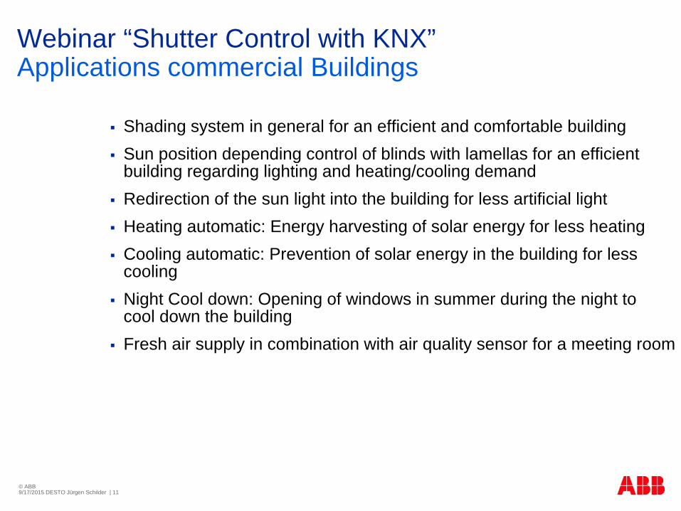
Webinar “Shutter Control with KNX”Applications commercial Buildings
Shading system in general for an efficient and comfortable building Sun position depending control of blinds with lamellas for an efficient
building regarding lighting and heating/cooling demand Redirection of the sun light into the building for less artificial light Heating automatic: Energy harvesting of solar energy for less heating Cooling automatic: Prevention of solar energy in the building for less
cooling Night Cool down: Opening of windows in summer during the night to
cool down the building Fresh air supply in combination with air quality sensor for a meeting room

Webinar “Shutter Control with KNX”Blinds up/down – step(open and close)/stop
Rocker 2move / travel
3/2/41
1.1.24
shutter sensorx-fold
Output AMove blinds
Up-Down3/2/41
1.1.29
shutter actuatorx-fold
Output ALouvre adj./
Stop Up-Down3/2/423/2/42Rocker 2
adjust lamella
Operationlong
(> 400msec.)
Operationshort
Move:„0“ – UP
„1“ - DOWN
Lamella/Slats:„0“ – OPEN
„1“ - CLOSE
1-bit
1-bit

© ABB9/17/2015 DESTO Jürgen Schilder | 13
Webinar “Shutter Control with KNX”Product and functional overview
The ABB i-bus® Blind/Roller Shutter Actuators are modular installation devices in Pro M design for installation in a distribution board
The devices are used for control of motors (230 V AC / 24 V DC) with sun protection products, such as blinds, roller shutters, Venetian blinds, awnings, roller blinds, curtains, vertical blinds, etc.
The control of binds/shutters via electrical drives saves the user not just manual raising and lowering of the blinds/shutters, but also enables fully automatic control. This type of control takes into consideration the time of day, the strength of the sunlight, the temperature conditions, the wind force etc. The shutter/blind is positioned in accordance with these factors. The user can also adjust this position manually to match individual requirements more precisely
The devices are also ideal for the control of ventilation flaps, skylights, doors, gates and other products that can be controlled via a drive

© ABB9/17/2015 DESTO Jürgen Schilder | 14
Webinar “Shutter Control with KNX”Product and functional overview
The Blind/Roller Shutter Actuators are powered via the ABB i-bus®
KNX and do not require an additional power supply
The connection to the KNX is implemented using the bus connection terminal
The device variants with manual operation JRA/S X.230.2.1 also feature push buttons on the device front
The connected drive manually adjusts the blinds/shutters connected to the drive, e.g. move UP/DOWN, STOP and slat adjustment UP/DOWN in steps
The front mounted LEDs indicate the current direction of movement or the current end position and status
The device variants JRA/S X.230.5.1 and JRA/S 4.24.5.1also feature manual operation via automatic travel detection via current detection

© ABB9/17/2015 DESTO Jürgen Schilder | 15
Webinar “Shutter Control with KNX”Product and functional overview
The output contacts for the UP and DOWN directions of motion are electro-mechanically mutually interlocked on all 230 V AC Blind/Roller Shutter Actuators
Simultaneous application of voltage would lead to destruction of the drives
The electro-mechanical interlocking feature ensures that both contacts can never have an applied voltage at the same time
The reversing delay when the direction changes can be set using parameters
The reaction on bus voltage failure and recovery as well as programming can be set individually

© ABB9/17/2015 DESTO Jürgen Schilder | 16
Webinar “Shutter Control with KNX”Product range overview
The right device for every application.Universal range for many sun protection technology applications.
2, 4, 8-fold Blind/Roller Shutter Actuators (230 V AC) with and without manual operation.Device for 24 V DC now also with manual operation and automatic travel detection.
JRA/S X.230.5.1
2-fold4-fold8-foldJRA/S
X.24.5.14-fold
JRA/S X.230.1.1
2-fold4-fold8-fold
JRA/S X.230.2.1
2-fold4-fold8-fold
„SMI“SJR/S
4.24.4.14x4f-fold LoVo
JA/S 4.SMI.1M4x4-fold

© ABB9/17/2015 DESTO Jürgen Schilder | 17
Webinar “Shutter Control with KNX”Device Overview JRA/S X.230.5.1, 4.24.5.1
JRA/S 2-, 4-, 8-fold 230 V and 4-fold 24 V DC With Travel Detection
With Manual Operation and status LEDs
The devices do not require an auxiliary voltage (only KNX)
Universal head screw terminals
4-fold 4-fold, 24 V DC2-fold 8-fold

© ABB9/17/2015 DESTO Jürgen Schilder | 18
Webinar “Shutter Control with KNX”Device Overview JRA/S X.230.2.1
JRA/S 2-, 4-, 8-fold 230 V With Manual Operation and status LEDs
Same application programm like JRA/S X.230.5.1-devices but withoutthe functions of „Travel Detection“
The devices do not require an auxiliary voltage (only KNX)
Universal head screw terminals
4-fold2-fold 8-fold

© ABB9/17/2015 DESTO Jürgen Schilder | 19
Webinar “Shutter Control with KNX”Device Overview JRA/S X.230.1.1
JRA/S 2-, 4-, 8-fold 230 V Without manual Operation and status LEDs
Same application programm like JRA/S X.230.5.1-devices but withoutthe functions of „Travel Detection“
The devices do not require an auxiliary voltage (only KNX)
Universal head screw terminals
4-fold2-fold 8-fold
© ABB9/17/2015 DESTO Jürgen Schilder | 20
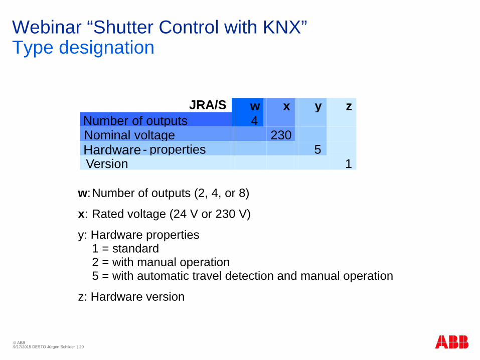
Webinar “Shutter Control with KNX”Type designation
w:Number of outputs (2, 4, or 8)
x: Rated voltage (24 V or 230 V)
y: Hardware properties1 = standard2 = with manual operation5 = with automatic travel detection and manual operation
z: Hardware version
JRA/S w x y zNumber of outputs 4Nominal voltage 230Hardware - properties 5Version 1

© ABB9/17/2015 DESTO Jürgen Schilder | 21
Webinar “Shutter Control with KNX”Connection to the blind and roller shutter drives
1 Label carrier2 LED3 Button4 Bus connection terminal
ABB i-bus® KNX5 Button and LED6 Button (2 per output)7 LEDs (2 per output)8 Screw terminals
(UP/DOWN, Phase L)

© ABB9/17/2015 DESTO Jürgen Schilder | 22
Webinar “Shutter Control with KNX”Connection to the blind and roller shutter drives
Important: Only one drive can be connected
per channel!
Parallel connection of several drives is not allowed reverse voltages may occur
A B

© ABB9/17/2015 DESTO Jürgen Schilder | 23
Webinar “Shutter Control with KNX”Connection to the blind and roller shutter drives
Blind/Roller Shutter Actuator 2-fold JRA/S 2.230.x.1
To control up to 2 independent blind and roller shutter drives (output A and B)
2 x 2 parallel relay outputs
A B

© ABB9/17/2015 DESTO Jürgen Schilder | 24
Webinar “Shutter Control with KNX”Connection to ventilation flaps/dampers or switch mode
1 Label carrier2 LED3 Button4 Bus connection terminal
ABB i-bus® KNX5 Button and LED6 Button (2 per output)7 LEDs (2 per output)8 Screw terminals
(UP/DOWN, Phase L)
© ABB9/17/2015 DESTO Jürgen Schilder | 25
Webinar “Shutter Control with KNX”Connection to 24V-DC drives
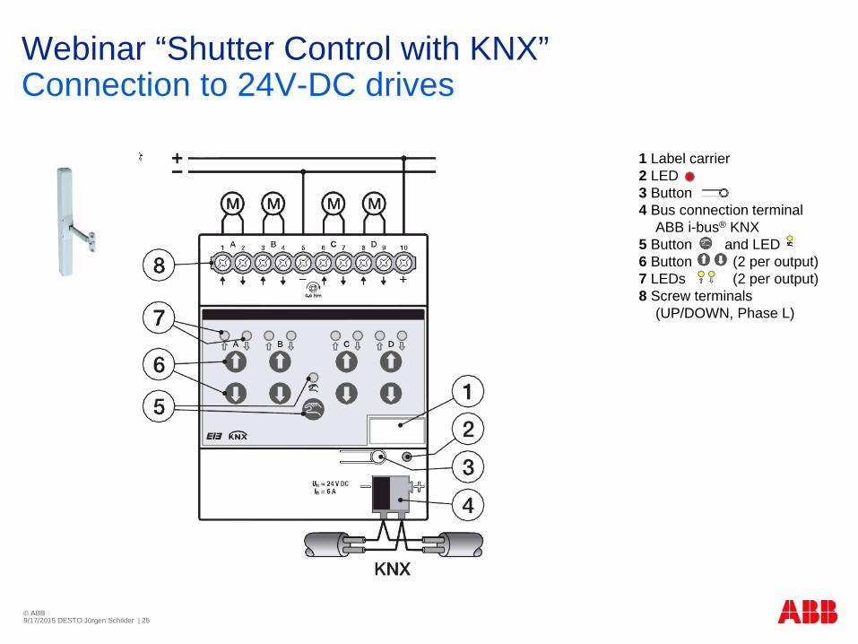
1 Label carrier2 LED3 Button4 Bus connection terminal
ABB i-bus® KNX5 Button and LED6 Button (2 per output)7 LEDs (2 per output)8 Screw terminals
(UP/DOWN, Phase L)

© ABB9/17/2015 DESTO Jürgen Schilder | 26
Webinar “Shutter Control with KNX”Safety
Electro-mechanically interlocked outputs prevent possible destruction of the drives
On a bus voltage failure, the default position of the bistable relay will be set even without an additional supply voltage
Un
M
NPE
M Mstop up down

© ABB9/17/2015 DESTO Jürgen Schilder | 27
Webinar “Shutter Control with KNX”Commissioning Power Supply NTI/Z 28.30.1
The commissioning power supply generates a DC voltage (no KNX!) and is used for on site commissioning of KNX devices should KNX system voltage be unavailable
Hence, the most important functions of a KNX device (e.g. Fan Coil Actuatoror Shutter Actuator) can be tested with manual operation
The output is permanently short-circuit proof and overload protected
Supply voltage Us 85…265 V AC
Output voltage UN 21…28 V DC SELV
Rated current IN 30 mA

© ABB9/17/2015 DESTO Jürgen Schilder | 28
Webinar “Shutter Control with KNX”Manual operation
The outputs can be directly controlled using the push buttons in manual operation
Accordingly, the wiring of the drives connected to the outputs can be verified during commissioning
You can, for example, ensure that the connected blind drives moves up and down correctly
If bus voltage is not yet available at the time of commissioning, the device can be supplied with power for manual operation using the Power Supply NTI/Z
Safety telegrams such as weather alarms, blocking and forced operation have the highest priority and block manual operation
This is carried out if manual operation is activated and a safety telegram is received
© ABB9/17/2015 DESTO Jürgen Schilder | 29
Webinar “Shutter Control with KNX”Manual operation
Push buttons are located on the front of the device for manual operation
Button „Manual operation“
Switch to „Manual operation“ and „KNX mode“
Button „Output A…X UP/DOWN“
KNX mode: No reaction
Manual operation: Long operation: UP/DOWN or opening/closing of the contact
Short operation: Slat adjustment /STOP
© ABB9/17/2015 DESTO Jürgen Schilder | 30
Webinar “Shutter Control with KNX”Manual operation
Function As standard button “manual operation” is enabled and switch on and off
is possible using it
Switch on of manual operation:
Press button until the yellow LED lights continuously
Switch off of manual operation:
Press button until the yellow LED switches off
The yellow LED flashes during the switchover process
After connection to the KNX, an ETS download or ETS reset the device is in KNX operation
The LED is off
All LEDs indicate their current state

© ABB9/17/2015 DESTO Jürgen Schilder | 31
Webinar “Shutter Control with KNX”Display elements
Indicator LEDs are located on the front of the device LED „Manual operation“
Off: The device is in KNX mode
On: The device is in manual mode
LED „Output A…X UP/DOW “
On : Upper limit position
On : Lower limit position
Both LED On: Safety function active, e.g. wind alarm
Flashes : Blind/shutter moving upwards
Flashes : Blind/shutter moving downwards
Both LEDs flash alternately (only JRA/S x.y.5.1): Malfunction drive fault (no current flow or invalid travel times)
Off: Intermediate position

© ABB9/17/2015 DESTO Jürgen Schilder | 32
Webinar “Shutter Control with KNX”Simplified commissioning: Copy and exchange
Copy one channel to one or more channels transferring the parameter settings
Exchange two channels
Copy / exchange with or without group addresses

© ABB9/17/2015 DESTO Jürgen Schilder | 33
Webinar “Shutter Control with KNX”Simplified commissioning: Convert
Convert of devices Conversion of application versions
Assume the parameter settings and group addresses from earlier application program versions
Furthermore, conversion can be applied to transfer the existing parameterization of a device to another device

© ABB9/17/2015 DESTO Jürgen Schilder | 34
Webinar “Shutter Control with KNX”Control with slat adjustment (blinds, vertical blinds, ..)
After the UP movement of the blind, the slats are generally open (horizontal slat position)
If the blind is moved downwards, the slats are initially closed (slat position vertical), and the blind moves downwards
If the blind is now once again moved upwards, the slats will once again be opened (slat position horizontal) and will then be moved upwards

© ABB9/17/2015 DESTO Jürgen Schilder | 35
Webinar “Shutter Control with KNX”Control with slat adjustment (blinds, vertical blinds, ..)
Short movements can be undertaken in order to purposely adjust the slat angle
Thus, the blind is moved for a brief programmed time – the so-called duration of slat adjustment – in steps in the required direction and in this way it undertakes a slat adjustment
The smaller the duration of slat adjustment selected, the more accurate the adjustment of the slat angle

© ABB9/17/2015 DESTO Jürgen Schilder | 36
Webinar “Shutter Control with KNX”Reaction on bus voltage failure
The reaction of each individual output at bus voltage failure can be parameterized
This parameterization acts directly on the output contacts and has the highest priority
If a bus voltage failure occurs during the movement, the blind/shutter can also move in the opposite direction of motion
After the contact positions are set with bus voltage recovery, the JRA/S remains non-functional, until the bus voltage recovers

© ABB9/17/2015 DESTO Jürgen Schilder | 37
Webinar “Shutter Control with KNX”Reaction on bus voltage failure
no reaction The output contacts remain in their current state
up/downThe blind/shutter (s) move up or down
StopIf the blind/shutter is performing a movement, this movement stops immediately. If the blind/shutter is at rest, it will remain unchanged in its position

no reaction: The output contacts remain in their current state up/down: The blind/shutter(s) move up or down stop: If the blind/shutter is performing a movement, this movement stops
immediately position 1…4: If one of these positions is selected, the blind/shutter (s)
move to a preset position individual position: Movement to one of the individual positions occurs
(position height in % [0...100] and position slat in % [0...100] enable automatic sun protection: The automatic is switched on
© ABB9/17/2015 DESTO Jürgen Schilder | 38
Webinar “Shutter Control with KNX”Reaction after bus voltage recovery /programming or ETS reset
© ABB9/17/2015 DESTO Jürgen Schilder | 39
Webinar “Shutter Control with KNX”Enhanced status messages
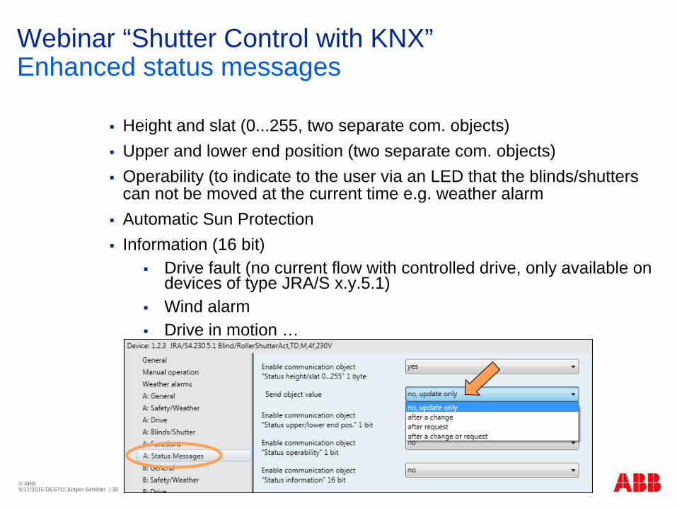
Height and slat (0...255, two separate com. objects) Upper and lower end position (two separate com. objects) Operability (to indicate to the user via an LED that the blinds/shutters
can not be moved at the current time e.g. weather alarm Automatic Sun Protection Information (16 bit)
Drive fault (no current flow with controlled drive, only available on devices of type JRA/S x.y.5.1)
Wind alarm Drive in motion …

© ABB9/17/2015 DESTO Jürgen Schilder | 40
Webinar “Shutter Control with KNX”Travel times (blinds, roller shutters, etc.)
The travel time is the time that the blind/shutter requires for a movement from fully upwards to fully downwards and vice versa
The movement times UP or DOWN can be separately determined and entered
If the JRA/S receives a movement telegram for upwards or downwards movement, the corresponding output is switched, and the blind/shutter is moved in the required direction

© ABB9/17/2015 DESTO Jürgen Schilder | 41
Webinar “Shutter Control with KNX”Automatic travel detection (only x.y.5.1)
The movement times of the drives are determined via the automatic travel detection
The duration of the current flow that the drive uses for the movement from the lower to the upper end position and vice versa is measured via current detection
This has the advantage that the ageing process and temperature related influences on the blind/shutter, e.g. expansion of the belts and cords on the blinds, are compensated
It facilitates exact positioning of the blind/shutter
Furthermore, the travel detection simplifies and accelerates commissioning and sends an error message, if the current flow is interrupted on the connected drive
Travel detection occurs automatically in ongoing operation or optionally via a communication object
The determined travel times serve as the basis for the calculation and control of positions or for the position feedbacks

© ABB9/17/2015 DESTO Jürgen Schilder | 42
Webinar “Shutter Control with KNX”Automatic travel detection (only x.y.5.1)
Determine the travel times via current detection
The travel times are automatically and permanently determined during ongoing operation and/or via object "Trigger travel detection“
Advantage
Compensation for changes in the length of the blind/shutter due to external influences (frost, UV rays or the use of heavier blind/shutter types)
Malfunction drive fault (no current flow or invalid travel times)

© ABB9/17/2015 DESTO Jürgen Schilder | 43
Webinar “Shutter Control with KNX”Set travel times
This method must be used on devices without travel detection (JRA/S x.230.2.1 and JRA/S x.230.1.1)
In this way, the travel times for the lower to the upper end position and vice versa are measured, e.g. via a stop watch
Using travel times, the current position of the blind/shutter is determined during ongoing operation

© ABB9/17/2015 DESTO Jürgen Schilder | 44
Webinar “Shutter Control with KNX”Set travel times
As an alternative to automatic travel detection, the devices of type JRA/S x.y.5.1 can use the manual method of travel detection via the application program
In this way, the travel times for the lower to the upper end position and vice versa are measured, e.g. via a stop watch
The measured values are then entered into the ETS parameter
This method must be used on devices without travel detection (JRA/S x.230.2.1 and JRA/S x.230.1.1)
Using travel times, the current position of the blind/shutter is determined during ongoing operation
For this reason, the travel times should be measured as precisely as possible and parameterized
Precise travel times are the basis for an exact calculation or positioning of the blind/shutter, in particular during positioning movements, automatic control or status messages

© ABB9/17/2015 DESTO Jürgen Schilder | 45
Webinar “Shutter Control with KNX”Travel times (blinds, roller shutters, etc.)
The blind/shutter is moved in this direction until the output receives a STOP telegram or the upper or lower limit positions are reached and the drive is switched off by the end limit switch
If the drive is switched off via the limit switch, the corresponding output contact remains closed, until the set total travel time has elapsed
Furthermore, the travel time can be extended by a parameterized overflow time
Only then there is no longer voltage on the output

© ABB9/17/2015 DESTO Jürgen Schilder | 46
Webinar “Shutter Control with KNX”Control with slat adjustment
Two methods are available for control of the slats and calculation of the slat turning times
1. Slat turning time via duration of slat adjustment (step)
With this method, the number and duration of slat adjustments that are required to turn the slats from fully closed to fully opened are set
Using the maximum number of slat adjustments, the current position of the slats is determined during ongoing operation
The max. number of slat adjustments must be counted by the operator and entered as a parameter

© ABB9/17/2015 DESTO Jürgen Schilder | 47
Webinar “Shutter Control with KNX”Control with slat adjustment
Two methods are available for control of the slats and calculation of the slat turning times
2. Slat turning time via total duration for slat turning
With this method, the time required by the slat to toggle from fully closed to fully opened is initially determined
Thereafter, the required number of slat adjustments (steps) that the slats will require from fully closed to fully opened is entered
The JRA/S then calculates the time required for a slat adjustment

© ABB9/17/2015 DESTO Jürgen Schilder | 48
Webinar “Shutter Control with KNX”Time-delayed switching of drives
In large KNX systems, a large starting current peak is generated if all drives start simultaneously due to central telegrams
The current peak can be limited by time delayed switching of the outputs
The time delay applies for all outputs or connected drives of the actuator
The central travel telegrams are executed with a delay Move to height for sun 0..255, Adjust slat for sun 0..255 Block, Forced operation Wind alarm, Rain alarm, Frost alarm …

© ABB9/17/2015 DESTO Jürgen Schilder | 49
Webinar “Shutter Control with KNX”Starting delay, coasting delay and minimum run time
Some drives do not deliver full power immediately
It is delivered after a starting delay of a few milliseconds
Other drives continue to run for a few milliseconds after switch off (stopping delay) or have a minimum run time
These parameters must only be entered should you require even more exact positioning of the blinds/shutters
Important Generally, the standard settings for these parameters are adequate to
ensure correct operation
If changes are to be made in the user-defined settings on these parameters, the technical data of the respective drive manufacturer should be observed!

© ABB9/17/2015 DESTO Jürgen Schilder | 50
Webinar “Shutter Control with KNX”Limitation of the travel range
For certain applications, the travelling range can be limited for the user
ExampleOpening and closing of the windows, doors or skylights can be limited to a certain group of users to a range of 0 to 20% opening, whereas the building caretaker may operate the complete range of movement
In addition to limitation of the travelling range, you can determine whether the upper and lower limit should be used for direct telegrams and/or for automatic telegrams

© ABB9/17/2015 DESTO Jürgen Schilder | 51
Webinar “Shutter Control with KNX”Limitation of the travel range
For certain applications, the travelling range of the blinds/shutters can be limited for the user
via object "Blinds/shutters up-down limited“ or
via object "Enable limitation"
The limitation only acts with a telegram to the communication object Blinds/shutters up-down limited and a scene telegram

© ABB9/17/2015 DESTO Jürgen Schilder | 52
Webinar “Shutter Control with KNX”Dead times
In a few rare cases, compensation for the mechanically present dead times of the blinds/shutters or slats is required
Parameters are available to compensate for the dead times and enable exact positioning
Important Generally, the standard settings for these parameters are adequate to
ensure correct operation
If changes are to be made in the user-defined settings on these parameters, the technical data of the respective blind/shutter manufacturer should be observed!

© ABB9/17/2015 DESTO Jürgen Schilder | 53
Webinar “Shutter Control with KNX”Dead times
The sun protection system dead times of the blind/shutter mechanisms can occur individually. They can be caused by ageing of the blind/shutter, e.g. mechanical loading. It may occur that precision positioning of the blind/shutter may no longer be possible.
Dead time blinds/shutters from bottom until moving up
Dead time of slat from 100% closed until slat turn
Slippage of blinds/shutters on change of direction

© ABB9/17/2015 DESTO Jürgen Schilder | 54
Webinar “Shutter Control with KNX”Tensioning of the awning/slot positioning
This function is used for
Tensioning or tightening textile blinds/shutters or
Setting so-called slot positioning on roller shutters
In this way, the blind/shutter is stopped at the end of a DOWN motion and moved in the opposite direction for a parameterizable time
In this way, for example, the awning cloth is tightened or light or ventilation slots are set on roller shutter

© ABB9/17/2015 DESTO Jürgen Schilder | 55
Webinar “Shutter Control with KNX”Tensioning of the awning/slot positioning
These parameters for slat adjustment are available exclusively in operation mode control without slat adjustment
This function is used for tensioning or tightening textile blinds/shutters (e.g. the cloth of an awning with articulated arms) or for setting slot positioning (e.g. light or ventilation slots) on roller shutters
In this way, the blind/shutter is stopped at the end of a DOWN motion and moved in the opposite direction for a parameterizable time
After each down command
Only after reaching lower end position

© ABB9/17/2015 DESTO Jürgen Schilder | 56
Webinar “Shutter Control with KNX”Priority for safety functions
The safety functions Wind alarm, Rain alarm, Frost alarm, Block and Forced operation have priority over all other functions
If one of these functions has been activated for an output, the operation of the output is disabled for other movements
A priority can also be defined for the safety functions among one another in order to precisely control the blinds/shutters, if more than one safety function is activated simultaneously
Example A parameter is used to determine that the forced operation has
priority when cleaning a window over a wind alarm, so that the cleaning personnel are not hindered by an upward movement due to a wind alarm when cleaning the slats

© ABB9/17/2015 DESTO Jürgen Schilder | 57
Webinar “Shutter Control with KNX”Forced operation
Each blind/shutter can also be moved individually into a forced position via a telegram (1 bit or 2 bit), and operation is disabled
On activation of the function forced operation function, the output is simultaneously informed about the position to which the blind/shutter should be moved
Operation of the blind/shutter is disabled
After a reset of forced operation, the blind/shutter is moved to the parameterized Position on reset of weather alarm, blocking and forced operation and operation is enabled
The function Forced operation is ideal, for example, to move shutters and blinds up and down, when windows have to be cleaned
At the same time, the operation of the blind/shutter is blocked to ensure that the cleaning personnel are not endangered by an unexpected movement

© ABB9/17/2015 DESTO Jürgen Schilder | 58
Webinar “Shutter Control with KNX”Forced operation
With the function Forced operation, the blind/shutter can move via a 1 bit telegram to a determined position or it can move up or down via 2 bit telegrams and operation can be blocked
activated (1 bit) Position height in % [0...100]
Position slat in % [0...100]
activated (2 bit) The communication object Forced operation 2 bit is enabled

© ABB9/17/2015 DESTO Jürgen Schilder | 59
Webinar “Shutter Control with KNX”Block
With the help of the function Block, an output of the JRA/S can be moved into a parameterized position via a 1 bit telegram, and the operation is disabled
When the function Block is recalled, the blind/shutter is moved to the set Position during blocking, and operation is blocked
After a reset, the blind/shutter is moved to the parameterized Position on reset of weather alarm, blocking and forced operation, and operation is enabled

© ABB9/17/2015 DESTO Jürgen Schilder | 60
Webinar “Shutter Control with KNX”Weather-dependent sensors
Outside Light Sensor LFO/A 1.1Interface for Outside Light Sensor HS/S 4.2.1
Weather Unit WZ/S 1.1 and Weather Sensor, WES/A 2.1
Weather Station WS/S 4.1 All common weather sensors can
be connected to the device(0-10V, 4-20mA, etc.)
© ABB9/17/2015 DESTO Jürgen Schilder | 61
Webinar “Shutter Control with KNX”Rain alarm and frost alarm
For protection against rain and freezing from frost, e.g. for awnings, the JRA/S can receive 1 bit rain alarm and frost alarm telegrams
In the event of an alarm, the blind/shutter is moved into the parameterized position and cannot be moved again, until the alarm is reset
The Position on rain alarm and Position for frost alarm can be set separately for each output

© ABB9/17/2015 DESTO Jürgen Schilder | 62
Webinar “Shutter Control with KNX”Wind alarm
The JRA/S can receive wind alarm telegrams (1 bit) to protect the blind/shutter in the event of wind and storms
If a wind alarm occurs, the blind/shutter is moved to the set Position on wind alarm and can no longer be moved, until the wind alarm has been deactivated again
The JRA/S can be controlled by up to 3 anemometers
It can be freely selected for each output, which of the three anemometers it should react to and whether the function Wind alarm should or should not be activated for this output
The Position on wind alarm can also be set separately for each output
The anemometers, which are assigned to an output, are linked by an OR function, i.e. if an alarm has been triggered by at least one of the associated anemometers, the blind/shutter is moved to the alarm position

© ABB9/17/2015 DESTO Jürgen Schilder | 63
Webinar “Shutter Control with KNX”Position on wind-, rain- and frost alarm
No reaction: It will remain unchanged in its position Up: The blind/shutter moves UP after a weather alarm is received Down: The blind/shutter moves DOWN after a weather alarm is received Stop: If the blind/shutter is performing a movement, this movement stops
immediately. If the blind/shutter is at rest, it will remain unchanged Position 1…4: If one of these positions is selected, the blind/shutter (s)
move to a preset position Individual position: Movement to one of the individual positions is
possible (position height in % [0...100] and position slat in % [0...100]) deactivated: No reaction occurs in the event of a weather alarm

© ABB9/17/2015 DESTO Jürgen Schilder | 64
Webinar “Shutter Control with KNX”Note for wind, rain alarm and frost alarm
The anemometer as well as rain sensor and the frost sensor are monitored cyclically by the JRA/S, i.e. the sensors send the alarm status cyclically and the JRA/S expects this signal
If the signal is not received, the JRA/S assumes that the sensor is defective or the bus line has been interrupted
All blinds/shutters that are influenced by the sensor are moved to the set alarm position, and operation is blocked
The monitoring period of the JRA/S should be twice as long as the cyclical sending time of the anemometer or rain/frost sensor, so that the blind/shutter does not move immediately to the rain or frost alarm position when a signal is not received, e.g. due to a high bus load
When the wind, rain or frost alarm is reset, the blind/shutter is moved to the set Position on reset of weather alarm, blocking and forced operation, and operation is enabled

© ABB9/17/2015 DESTO Jürgen Schilder | 65
Webinar “Shutter Control with KNX”Positions – Reference movement
Every output permanently determines the current position of the blind/shutter as well as the position of the slat angle based on the duration of the individual movement actions
Slight inaccuracies can occur over extended periods in the determination of the position due to temperature fluctuations and ageing
For this reason, the JRA/S uses the upper and lower end positions for unique determination of the current position of the blinds/shutters
Every time when the blind/shutter is in the upper end position, the position is updated in the memory of the device
If the end positions are not reached in normal operation, a reference movement, which is fully upwards or fully downwards, can be performed via a telegram
After a reference movement, the blind/shutter remains in the reference position or moves back to the stored position as specified in the programming

© ABB9/17/2015 DESTO Jürgen Schilder | 66
Webinar “Shutter Control with KNX”Positions – Move to position 0 % ... 100 %
The blinds/shutters can be moved into any position via an 8 bit value
In the control with slat adjustment operation mode, the slats can also be positioned into any angle via an 8 bit value
In this way, it can be decided for each movement telegram which position the blind/shutter should move to, and it is possible to set the position from a display or a visualisation terminal

© ABB9/17/2015 DESTO Jürgen Schilder | 67
Webinar “Shutter Control with KNX”Positions – Move to preset position
For each output, it is possible to parameterize up to 4 preset positions individually, which are then recalled via a 1 bit telegram
When moving into one of these preset positions, the target position must first be set, either via the parameters during programming or via the function “Set preset position”
This preset target position can then, for example, be recalled as often as required by pressing a push button

© ABB9/17/2015 DESTO Jürgen Schilder | 68
Webinar “Shutter Control with KNX”Positions – Set preset position
The preset position can be changed very easily via a 1 bit telegram
To do so, the blinds are moved into the required new preset position via UP/DOWN telegrams as well as STOP/slat adjustment UP/DOWN telegrams
The new position is adopted via a 1 bit telegram as a new preset position into the memory of the device
The saved preset values are retained with a bus voltage failure
With the programming it is possible to set via a parameter if the saved values should be overwritten by the parameterized values
Example The shutters are moved into a preset position after a short push
button action, and the current position is adopted as the new preset position after a long push button action
© ABB9/17/2015 DESTO Jürgen Schilder | 69
Webinar “Shutter Control with KNX”Positions – 8 bit scene
With the 8 bit scene, up to 64 scenes are managed via a single group address
An 8 bit scene telegram contains the following information:
Number of the scene (1…64) as well as
Store/recall scene
The JRS/A receives the telegram
All the outputs, which are assigned to the received scene number via a parameter, move to the recalled scene position or store their current position as a new default value for this scene number
Each individual output of the device can be integrated into up to eighteen 8 bit scenes

© ABB9/17/2015 DESTO Jürgen Schilder | 70
Webinar “Shutter Control with KNX”Positions – 8 bit scene
Example The first three outputs of the device are assigned to the following
scenes:Output Scene No. Specified position Specified slatA 5 20 % 50 %A 9 47 % 30 %A 45 70 % 80 %B 5 20 % 50 %B 37 82 % 65 %B 45 75 % 31 %C 58 65 % 77 %
If scene no. 5 is now recalled, the blinds/shutters on outputs A and B will move to the saved preset positions and align the slats in accordance with the saved preset value
The blind/shutter on output C is not assigned to scene No. 5 and will therefore not move

© ABB9/17/2015 DESTO Jürgen Schilder | 71
Webinar “Shutter Control with KNX”Positions – 8 bit scene
Each blind/shutter output can be integrated in up to 18 scenes
If a telegram is received on the communication object “Scene”, all outputs assigned to the sent scene number will then move to the saved scene position (call a scene), or the current position will be saved as a new scene position (store a scene)
Position height in % [0...100]
Position slat in % [0...100]

© ABB9/17/2015 DESTO Jürgen Schilder | 72
Webinar “Shutter Control with KNX”Automatic control
Sun protection (standard)
Sun protection with tracking of the sun’s position
Heating/cooling automatic
Redirection of daylight
Night cool down

© ABB9/17/2015 DESTO Jürgen Schilder | 73
Webinar “Shutter Control with KNX”Automatic control – sun protection
It is possible to set up a very convenient automatic sun protection system by combining Blind/Roller Shutter Actuator JRA/S with other KNX components
The automatic sun protection controls the shutter/blind according to the level of sunlight
Depending on the strength and direction of the sun, the shutter/blind is moved into a set position via an 8 bit value or into a variable position depending on the situation
For example, the blind can be raised if the sun is only weak or is not shining on the window at all
As much light as possible is thereby let into the room without any disruptive direct sunlight being taken into account

© ABB9/17/2015 DESTO Jürgen Schilder | 74
Webinar “Shutter Control with KNX”Automatic control – sun protection (standard)
If there is blazing sun on the window however, the blind is lowered and the louvres are closed to the extent that direct sunlight cannot penetrate the room
The residual opening in the blinds lets in a sufficient level of diffuse light into the room
No sunBlind raised
Sun Blind lowered
and louvres closed

© ABB9/17/2015 DESTO Jürgen Schilder | 75
Webinar “Shutter Control with KNX”Automatic control – sun protection (standard)
Two further components are required:
An activation option for the user (e.g. a further switch sensor or the second rocker of the UP/DOWN switch sensor) and
a brightness sensor
With the help of the second switch sensor, the user of the room can specify whether he wishes to use the automatic sun protection or whether he would rather control the shutters/blinds manually
If the automatic sun protection is activated via a switch sensor, the shutter/blind moves automatically until either the automatic sun protection is deactivated via the same switch sensor or the user issues a direct movement command (e.g. UP/DOWN or move into position) and the automatic function is thus also deactivated
Webinar “Shutter Control with KNX”Automatic control – sun protection (standard)
Brightnesssensor
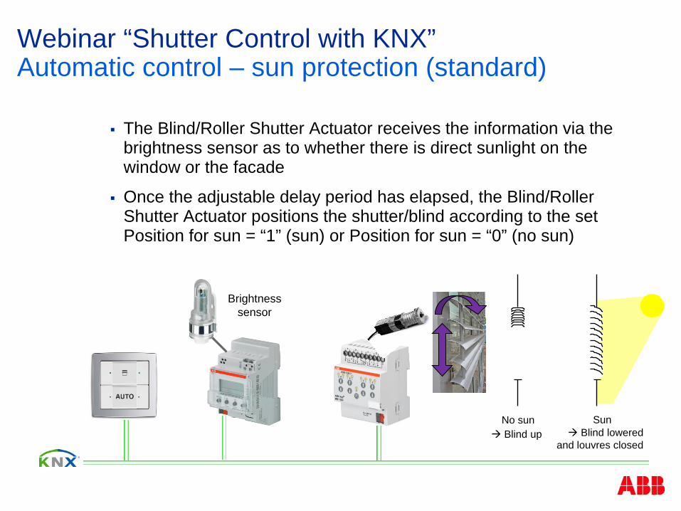
The Blind/Roller Shutter Actuator receives the information via the brightness sensor as to whether there is direct sunlight on the window or the facade
Once the adjustable delay period has elapsed, the Blind/Roller Shutter Actuator positions the shutter/blind according to the set Position for sun = “1” (sun) or Position for sun = “0” (no sun)
No sun Blind up
Sun Blind lowered
and louvres closed

© ABB9/17/2015 DESTO Jürgen Schilder | 77
Webinar “Shutter Control with KNX”Automatic control – sun protection (standard)
Automaticcontrol
activated
Position forsun = „1“
Position forsun = „0“
Brightnesssensor
DirectUP/DOWN
„1“
Automaticcontrol
deactivated
Direct positioningvia UP/DOWN or
movement toposition
„0“
Shutter Actuator
„1“ = sun
„0“ = no sun

© ABB9/17/2015 DESTO Jürgen Schilder | 78
Webinar “Shutter Control with KNX”Automatic control – sun protection (standard)
Automaticcontrol
activated
Position forsun = „1“
Position forsun = „0“
Brightnesssensor
DirectUP/DOWN
„1“
Automaticcontrol
deactivated
Direct positioningvia UP/DOWN or
movement toposition
„0“
Shutter Actuator
„1“ = sun
„0“ = no sun

© ABB9/17/2015 DESTO Jürgen Schilder | 79
Webinar “Shutter Control with KNX”Automatic control – sun protection with tracking of the sun’s position
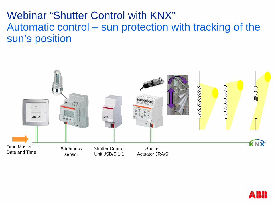
To set up an automatic sun protection system with tracking of the sun’s position, an additional control unit is required (e.g. the Shutter Control Unit JSB/S 1.1)
The current position of the sun is continually calculated in the shutter control unit
The shutter/blind is moved via an 8 bit value into the optimum position to deflect direct sunshine but to let through as much diffuse light as possible
The influence of shadows e.g. the buildings opposite can also be taken into account in the shutter control unit
Webinar “Shutter Control with KNX”Automatic control – sun protection with tracking of the sun’s position
Brightnesssensor
Time Master: Date and Time
Shutter Control Unit JSB/S 1.1
Shutter Actuator JRA/S

Autocontrol
© ABB9/17/2015 DESTO Jürgen Schilder | 81
Webinar “Shutter Control with KNX”Automatic control – sun protection with tracking of the sun’s position
Automaticcontrol
activated
Move to 8-bitposition and slat
Position forsun = „0“
Brightnesssensor
DirectUP/DOWN
„1“
Automaticcontrol
deactivated
Direct positioning via UP/DOWN or movement to
position
„0“
Shutter Actuator
Shutter control unit JSB/S
„0“ = no sun
„1“ = sun and8-bit value
position and slat

Autocontrol
© ABB9/17/2015 DESTO Jürgen Schilder | 82
Webinar “Shutter Control with KNX”Automatic control – sun protection with tracking of the sun’s position
Automaticcontrol
activated
Move to 8-bitposition and slat
Position forsun = „0“
Brightnesssensor
DirectUP/DOWN
„1“
Automaticcontrol
deactivated
Direct positioning via UP/DOWN or movement to
position
„0“
Shutter Actuator
Shutter control unit JSB/S „1“ = sun and
8-bit valueposition and slat
„0“ = no sun

© ABB9/17/2015 DESTO Jürgen Schilder | 83
Webinar “Shutter Control with KNX”Automatic control – Automatic heating/cooling
The automatic heating/cooling is an enhancement of the automatic sun protection
During absences the automatic heating/cooling function controls the shutter/blind according to the sunlight and the required energy input in the room
The shutter/blind is moved into a set position depending on whether the room should be heated or cooled and how strong the sun is and in which direction it is shining
The following parameters are linked for the function Heating/cooling automatic:
Absence of persons
Sun
Heating or cooling period

© ABB9/17/2015 DESTO Jürgen Schilder | 84
Webinar “Shutter Control with KNX”Automatic control – Automatic heating/cooling
The shutter can for example be raised during the heating phase when the sun is shining to achieve a maximum energy input into the room
Heating period
Sun outside up
No sun outside down

© ABB9/17/2015 DESTO Jürgen Schilder | 85
Webinar “Shutter Control with KNX”Automatic control – Automatic heating/cooling
During the cooling phase, the blind can be lowered during full sunshine in order to keep the energy input at a minimum
Cooling period
Sun outside down
No sun outside up

© ABB9/17/2015 DESTO Jürgen Schilder | 86
Webinar “Shutter Control with KNX”Automatic control – Automatic heating/cooling
Two further components are required in addition to the automatic sun protection
A toggling option between automatic sun protection and automatic heating/cooling (e.g. a presence detector) as well as
A toggling option between heating and cooling (e.g. a year time switch or a temperature sensor)
With the help of the switch sensor, the user of the room can specify whether he wishes to use the automatic control or whether he would rather control the shutters/blinds manually
If the automatic sun protection is activated via a switch sensor, the shutter/blind moves automatically until either the automatic function is deactivated via the same switch sensor or the user issues a direct movement command (e.g. UP/DOWN or move into position)

© ABB9/17/2015 DESTO Jürgen Schilder | 87
Webinar “Shutter Control with KNX”Automatic control – Automatic heating/cooling
The Blind/Roller Shutter Actuator receives the information via the presence detector as to whether there are people in the room
If the room is occupied, the blind is controlled according to the automatic sun protection function
If nobody is in the room, the blind is controlled according to the automatic heating/cooling function
For example, the Shutter Actuator receives the information via a year time switch or a thermostat as to whether the room should be heated or cooled
The blind moves into the set heating or cooling position, depending on the position and intensity of the sun

© ABB9/17/2015 DESTO Jürgen Schilder | 88
Webinar “Shutter Control with KNX”Automatic control – Automatic heating/cooling
Automaticcontrol
activatedBrightness
sensor
DirectUP/DOWN
„1“
Automaticcontrol
deactivated
Direct positioningvia UP/DOWN or
movement toposition
„0“
Shutter Actuator
Presence detector
„0“
„1“
Automaticsun
protection
Heating/ cooling
automatic
Position forsun = „1“sun = „0“
Position forheating = „1“ and
sun = „0“/sun = „1“
Position forcooling = „1“ and
sun = „0“/sun = „1“
Heating
Cooling
or

© ABB9/17/2015 DESTO Jürgen Schilder | 89
Webinar “Shutter Control with KNX”Automatic control – Automatic heating/cooling
Automaticcontrol
activatedBrightness
sensor
DirectUP/DOWN
„1“
Automaticcontrol
deactivated
Direct positioningvia UP/DOWN or
movement toposition
„0“
Shutter Actuator
Presence detector
„0“
„1“
Automaticsun
protection
Heating/ cooling
automatic
Position forsun = „1“sun = „0“
Position forheating = „1“ and
sun = „0“/sun = „1“
Position forcooling = „1“ and
sun = „0“/sun = „1“
Heating
Cooling
or

© ABB9/17/2015 DESTO Jürgen Schilder | 90
Webinar “Shutter Control with KNX”Automatic control – Automatic heating/cooling
Overheat control (during automatic heating/cooling is active) Heat up of the unoccupied room is avoided using overheat control
During the heating period, rooms with large glass fronts can heat up very quickly in strong sunshine, even if the external temperature is low
Overheat control is used in order to avoid the need for any cooling energy
If the temperature threshold here is reached or exceeded, the blinds/shutters will move to a parameterizable position, e.g. DOWN
If the temperature value drops by more than 3 degrees Kelvin, overheat control is ended
The blinds/shutters are then moved to the parameterized position

© ABB9/17/2015 DESTO Jürgen Schilder | 91
Webinar “Shutter Control with KNX”Automatic control – Automatic heating/cooling
Overheat control (during automatic heating/cooling is active) Heat up of the unoccupied room is avoided using overheat control
If the temperature threshold here is reached or exceeded, the blinds/shutters will move to a parameterizable position, e.g. DOWN

© ABB9/17/2015 DESTO Jürgen Schilder | 92
Webinar “Shutter Control with KNX”Automatic control – redirection of daylight
When using special directional louvres, the direct light into the room is guided so that the no disruptive direct light penetrates the room but at the same time optimum use is made of the existing natural daylight

© ABB9/17/2015 DESTO Jürgen Schilder | 93
Webinar “Shutter Control with KNX”Automatic control – Night cool down
Using the Night cool down automatic function it is possible to implement cooling of rooms by temperature dependent ventilation
It is not useful to always open the window at fixed times
Example: The window of a production hall should be opened for cooling early in the morning before work starts in summer
The internal and external temperature must be measured
Two conditions must also be fulfilled:
Internal temperature is higher than the external temperature
External temperature is lower than a defined fixed value, e.g. 18°C

© ABB9/17/2015 DESTO Jürgen Schilder | 94
Webinar “Shutter Control with KNX”SMI
SMI = Standard Motor Interface
First standard for the connection of intelligent drives for shutters, windows and sun protection systems
SMI enables telegram transmission from the control unit to the drive and vice versa
www.smi-group.com

© ABB9/17/2015 DESTO Jürgen Schilder | 95
Webinar “Shutter Control with KNX”SMI
SMI is the abbreviation for STANDARD MOTOR INTERFACE and is the standardised electrical connection for shutter, windows and sun protection system drives
Renowned European manufacturers have joined the SMI Consortium to develop the digital interface
Using this standard interface drives are controlled via data packages
Thanks to this technology, SMI drives provide precise feedback
A parallel connection of up to 16 drives is possible which can each be individually addressed
SMI drives are available for mains voltage (230V) and low voltage (LoVo)

© ABB9/17/2015 DESTO Jürgen Schilder | 96
Webinar “Shutter Control with KNX”SMI Group
Member
Partner, e.g.

© ABB9/17/2015 DESTO Jürgen Schilder | 97
Webinar “Shutter Control with KNX”www.smi-group.com

© ABB9/17/2015 DESTO Jürgen Schilder | 98
Webinar “Shutter Control with KNX”SMI
Master-Slave System
Connection of up to 16 drives (slaves) at 1 SMI output (master)
Broadcast, group and individual addressing
Motor response
motor is rotating
direction of rotation
motor defect
Precise positioning (2° / Step)
Push button operation possible
Names and colour codes of the wires for connecting SMI systems

© ABB9/17/2015 DESTO Jürgen Schilder | 99
Webinar “Shutter Control with KNX”SMI
Connection via 5-core wire
I+,I-: SMI telegram transfer
L, N, PE: Power supply
Free topology
SMI cable length max. 350 m
SMI control voltage 18V DC
Data transfer 2400 bit/s
SMI signal lines are protected against polarity reversal so that an incorrect connection cannot damage the actuator or drives
The I+ and I- SMI wires can be laid in the motor connection line of the SMI drive or in their own cable
Names and colour codes of the wires for connecting SMI systems

© ABB9/17/2015 DESTO Jürgen Schilder | 100
Webinar “Shutter Control with KNX”Conductor assignment for SMI drives for mains voltage

© ABB9/17/2015 DESTO Jürgen Schilder | 101
Webinar “Shutter Control with KNX”SMI
SMI-Planning manual SMI and building management
(technology, …)
Development (positioning, advantages, fields of application, …
Planning (principles of sun protection automation, SMI-drive systems, standards, …)
Installation (connection scheme, SMI-easy monitor, manual control cable …)

Webinar “Shutter Control with KNX”SMI
© ABB17.09.2015 DESTO Jürgen Schilder | 102
LoVo
Communication with
feedback
4 independent groups with up to 4 SMI drives
per output
JA/S4.SMI.1M
SJR/S4.24.2.1 LoVo

© ABB9/17/2015 DESTO Jürgen Schilder | 103
Webinar “Shutter Control with KNX”SMI – JA/S 4.SMI.1M
The Shutter Actuator JA/S 4.SMI.1M controls
four independent groups (Broadcast Mode)
each with up to 4 SMI shutter or roller blind drives (230 V Motors)
via the KNX
No SMI commissioning necessary
Status signals (motor fault, direction of movement) can also be sent from the SMI drive on KNX
Manual operation
Status LEDs

© ABB9/17/2015 DESTO Jürgen Schilder | 104
Webinar “Shutter Control with KNX”SMI – SJR/S4.24.2.1 LoVo
The Shutter Actuator SJR/S4.24.2.1 LoVo controls
four independent groups (Broadcast Mode)
each with up to 4 SMI shutter or roller blind drives (24 V Motors -SMI LoVo)
via the KNX
No SMI commissioning necessary
Status signals (motor fault, direction of movement) can also be sent from the SMI drive on KNX
Manual operation
Status LEDs

© ABB9/17/2015 DESTO Jürgen Schilder | 105
Webinar “Shutter Control with KNX”SMI
JA/S 4.SMI.1M SJR/S 4.24.2.1

© ABB9/17/2015 DESTO Jürgen Schilder | 106
Webinar “Shutter Control with KNX”SMI
The following functions are available with the application program Move UP/DOWN, Stop/Louvre adjustment
Move into position (up to 4 preset positions)
Set position (modification of the preset position via KNX)
Move to position 0…100 %
Scenes
Sun automatic control
Heating/cooling automatic control
Monitoring of wind, rain and frost alarms (cyclical)
Block and forced operation
Status messages
…
© ABB9/17/2015 DESTO Jürgen Schilder | 107
Webinar “Shutter Control with KNX”SMI
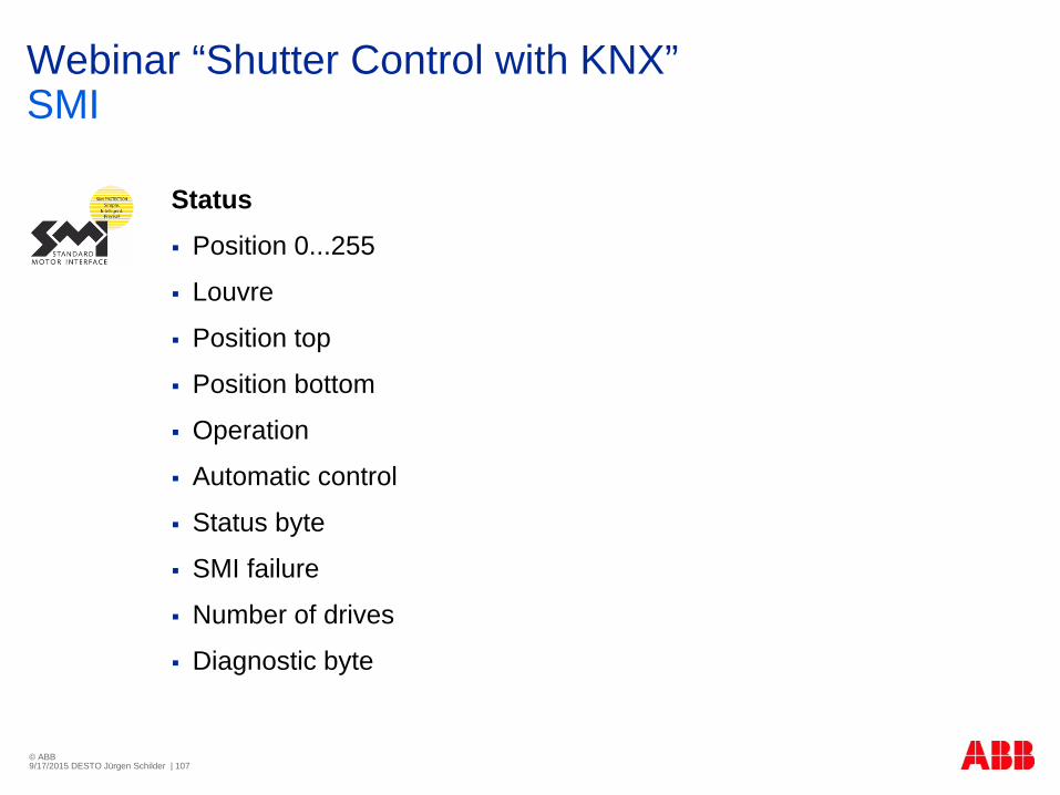
Status Position 0...255
Louvre
Position top
Position bottom
Operation
Automatic control
Status byte
SMI failure
Number of drives
Diagnostic byte

© ABB9/17/2015 DESTO Jürgen Schilder | 108
Webinar “Shutter Control with KNX”SMI – Status messages (each output)
One object „SMI failure“(1 bit) “0“: SMI ok “1“: SMI or 230V/24V (motor) has failed
One object „number of drives“(1 bit) “0“: = number of drives o.k. “1” = number of drives too high/ too low
One object ”diagnostic byte“(1 Byte): 7: No communication 6: Motor moves up 5: Motor moves down 4: Motor fault 3: Short-circuit on SMI (hardware fault) 2: More drives detected than configured 1: Less drives detected than configured 0: More than 4 drives detected on SMI

© ABB9/17/2015 DESTO Jürgen Schilder | 109
Webinar “Shutter Control with KNX”i-bus® Tool

© ABB9/17/2015 DESTO Jürgen Schilder | 110
Blind/Roller Shutter Actuator JRA/S i-bus® Tool

© ABB9/17/2015 DESTO Jürgen Schilder | 111
Webinar “Shutter Control with KNX”www.abb.com/knx product tree shutters

© ABB9/17/2015 DESTO Jürgen Schilder | 112
Webinar “Shutter Control with KNX”Documentation
Product Manual
Product Information
Application Manual“Shutter Control“
Technical datasheet

© ABB9/17/2015 DESTO Jürgen Schilder | 113
Webinar “Shutter Control with KNX”E-Learning module – www.abb.com/knx

© ABB9/17/2015 DESTO Jürgen Schilder | 114