journal of mechanics of materials and structuressdg/preprint/zsshell.pdf · 2011-07-05 · journal...
TRANSCRIPT

Journal of
Mechanics ofMaterials and Structures
A ZERO-STIFFNESS ELASTIC SHELL STRUCTURE
Simon D. Guest, Elizbar Kebadze and Sergio Pellegrino
Volume 6, No. 1-4 January–June 2011
mathematical sciences publishers
JOURNAL OF MECHANICS OF MATERIALS AND STRUCTURESVol. 6, No. 1-4, 2011
msp
A ZERO-STIFFNESS ELASTIC SHELL STRUCTURE
SIMON D. GUEST, ELIZBAR KEBADZE AND SERGIO PELLEGRINO
A remarkable shell structure is described that, due to a particular combination of geometry and initialstress, has zero stiffness for any finite deformation along a twisting path; the shell is in a neutrally stablestate of equilibrium. Initially the shell is straight in a longitudinal direction, but has a constant, nonzerocurvature in the transverse direction. If residual stresses are induced in the shell by, for example, plasticdeformation, to leave a particular resultant bending moment, then an analytical inextensional model ofthe shell shows it to have no change in energy along a path of twisted configurations. Real shells becomecloser to the inextensional idealization as their thickness is decreased; experimental thin-shell modelshave confirmed the neutrally stable configurations predicted by the inextensional theory. A simple modelis described that shows that the resultant bending moment that leads to zero stiffness gives the shell ahidden symmetry, which explains this remarkable property.
1. Introduction
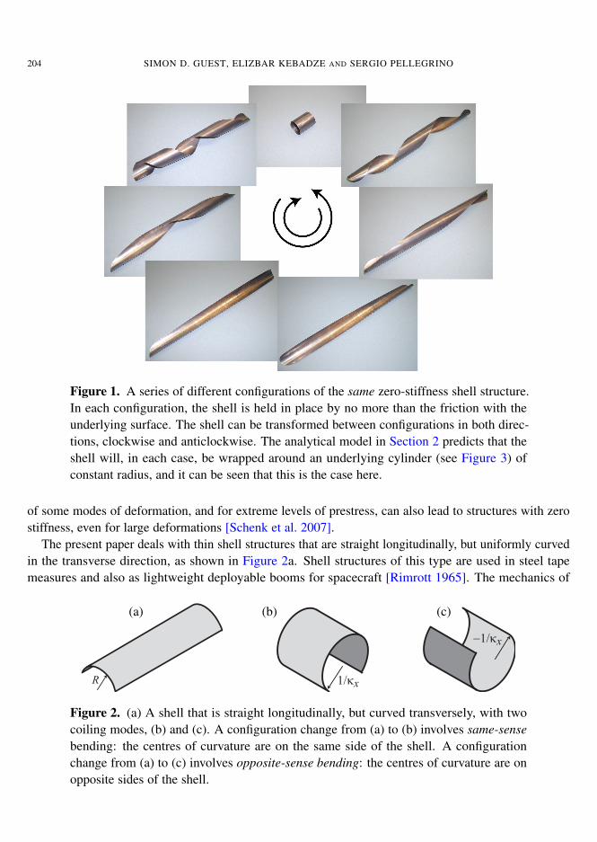
A novel zero-stiffness structure is described. The structure is a thin shell that is initially straight in alongitudinal direction, but has a uniform, nonzero curvature in the transverse direction. The structure isprestressed, and the interaction of the elastic properties with the prestress is such that the structure canbe deformed without any applied load; this is not a local phenomenon — the structure can continue tobe deformed in a finite closed path. Equivalently, the structure is neutrally stable: there is no change intotal internal strain energy as the structure is deformed, even though any particular component of strainenergy will vary. An experimental model of this structure, made from a sheet of copper beryllium ofthickness 0.1 mm and width 30 mm, is shown in Figure 1.
The ability to deform a structure without load is quite unexpected when initially observed, and isclearly a function of the prestress that the shell carries. Certainly it is well known that the stiffnessof structures changes with applied load. Stable structures can become unstable when loaded: a simpleexample is the buckling of a strut through the application of axial load. At the cusp between stabilityand instability there may then be a point of neutral stability, where a structure has zero stiffness: to firstorder, there is no change in load with displacement. However, while typically for buckling phenomenathis point of neutral stability/zero stiffness is isolated, it is also possible to engineer systems which, whenthey buckle, are neutrally stable for large deformations [Tarnai 2003].
The stiffness of structures also changes through prestress, where the structure is loaded against itself.A classical example of this behaviour is provided by tensegrity structures [Calladine 1978; Guest 2011],which typically rely on prestress in order to be able to act as structures at all. However, even for tenseg-rities with rigid compression members, increasing the relative level of prestress can reduce the stiffness
Keywords: zero-stiffness, morphing structure, reconfigurable structure.
203
204 SIMON D. GUEST, ELIZBAR KEBADZE AND SERGIO PELLEGRINO
Figure 1. A series of different configurations of the same zero-stiffness shell structure.In each configuration, the shell is held in place by no more than the friction with theunderlying surface. The shell can be transformed between configurations in both direc-tions, clockwise and anticlockwise. The analytical model in Section 2 predicts that theshell will, in each case, be wrapped around an underlying cylinder (see Figure 3) ofconstant radius, and it can be seen that this is the case here.
of some modes of deformation, and for extreme levels of prestress, can also lead to structures with zerostiffness, even for large deformations [Schenk et al. 2007].
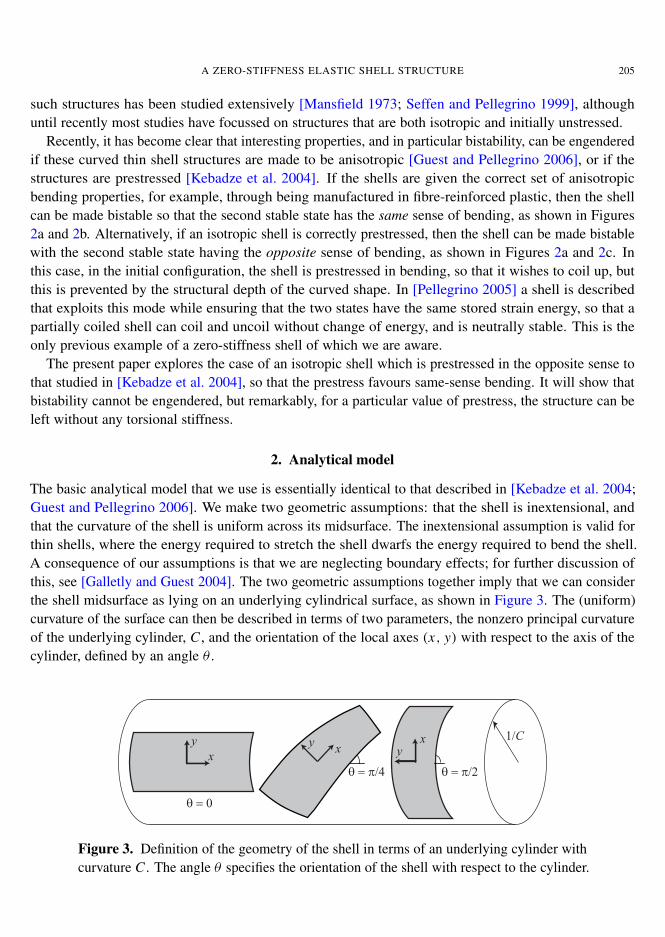
The present paper deals with thin shell structures that are straight longitudinally, but uniformly curvedin the transverse direction, as shown in Figure 2a. Shell structures of this type are used in steel tapemeasures and also as lightweight deployable booms for spacecraft [Rimrott 1965]. The mechanics of
(a) (b) (c)
R 1/κx
−1/κx
Figure 2. (a) A shell that is straight longitudinally, but curved transversely, with twocoiling modes, (b) and (c). A configuration change from (a) to (b) involves same-sensebending: the centres of curvature are on the same side of the shell. A configurationchange from (a) to (c) involves opposite-sense bending: the centres of curvature are onopposite sides of the shell.
A ZERO-STIFFNESS ELASTIC SHELL STRUCTURE 205
such structures has been studied extensively [Mansfield 1973; Seffen and Pellegrino 1999], althoughuntil recently most studies have focussed on structures that are both isotropic and initially unstressed.
Recently, it has become clear that interesting properties, and in particular bistability, can be engenderedif these curved thin shell structures are made to be anisotropic [Guest and Pellegrino 2006], or if thestructures are prestressed [Kebadze et al. 2004]. If the shells are given the correct set of anisotropicbending properties, for example, through being manufactured in fibre-reinforced plastic, then the shellcan be made bistable so that the second stable state has the same sense of bending, as shown in Figures2a and 2b. Alternatively, if an isotropic shell is correctly prestressed, then the shell can be made bistablewith the second stable state having the opposite sense of bending, as shown in Figures 2a and 2c. Inthis case, in the initial configuration, the shell is prestressed in bending, so that it wishes to coil up, butthis is prevented by the structural depth of the curved shape. In [Pellegrino 2005] a shell is describedthat exploits this mode while ensuring that the two states have the same stored strain energy, so that apartially coiled shell can coil and uncoil without change of energy, and is neutrally stable. This is theonly previous example of a zero-stiffness shell of which we are aware.
The present paper explores the case of an isotropic shell which is prestressed in the opposite sense tothat studied in [Kebadze et al. 2004], so that the prestress favours same-sense bending. It will show thatbistability cannot be engendered, but remarkably, for a particular value of prestress, the structure can beleft without any torsional stiffness.
2. Analytical model
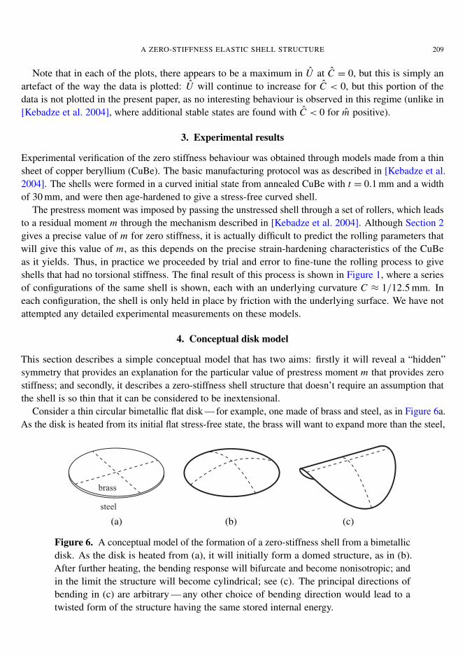
The basic analytical model that we use is essentially identical to that described in [Kebadze et al. 2004;Guest and Pellegrino 2006]. We make two geometric assumptions: that the shell is inextensional, andthat the curvature of the shell is uniform across its midsurface. The inextensional assumption is valid forthin shells, where the energy required to stretch the shell dwarfs the energy required to bend the shell.A consequence of our assumptions is that we are neglecting boundary effects; for further discussion ofthis, see [Galletly and Guest 2004]. The two geometric assumptions together imply that we can considerthe shell midsurface as lying on an underlying cylindrical surface, as shown in Figure 3. The (uniform)curvature of the surface can then be described in terms of two parameters, the nonzero principal curvatureof the underlying cylinder, C , and the orientation of the local axes (x, y) with respect to the axis of thecylinder, defined by an angle θ .
q = p/4
q = 0
q = p/2
1/Cx
y xyxy
Figure 3. Definition of the geometry of the shell in terms of an underlying cylinder withcurvature C . The angle θ specifies the orientation of the shell with respect to the cylinder.

206 SIMON D. GUEST, ELIZBAR KEBADZE AND SERGIO PELLEGRINO
The curvature of the shell can thus be described by the curvature vector κ :
κ =
κx
κy
2κxy
= C2
1− cos 2θ1+ cos 2θ
2 sin 2θ
. (1)
The curvature components are given by κx = −∂2w/dx2, κy = −∂
2w/dy2, and κxy = −∂2w/dx dy,
where w is the relative displacement out of the plane defined by x and y. The transformation to the x, ycurvilinear coordinates is obtained from, for example, a Mohr circle construction, as described in [Guestand Pellegrino 2006]. Note that the definition κxy =−∂
2w/dx dy for the twisting curvature is standardin the plates and shells literature, including [Kebadze et al. 2004], but is only half the value commonlyused in the composites literature, including [Guest and Pellegrino 2006].
We assume an initial configuration for the shell with θ0 = 0 and C0 = 1/R, so the change in curvatureto any other configuration is given by
1κ =C2
1− cos 2θ
1+ cos 2θ − 2C R
2 sin 2θ
. (2)
We also assume that the shell is prestressed in the initial configuration. As the shell is straight in thex-direction, it cannot sustain any moment/unit length along the edge normal to the y-axis, so in theinitial configuration m y = mxy = 0. However, because of the curvature in the y-direction, the depth ofthe cross-section allows a uniform initial moment mx = m to be equilibrated by midplane forces in theshell, as shown in Figure 4.
In a general configuration we define the moment/unit length carried by the shell as a vector m,
m =
mx
m y
mxy
, (3)
m
Figure 4. Initial prestress in the shell. The uniform moment/unit length mx = m isequilibrated by a distribution of midplane forces in the shell. The moment m is uniformthroughout the shell, except for a narrow boundary layer at the free ends.

A ZERO-STIFFNESS ELASTIC SHELL STRUCTURE 207
with an initial value
m0 =
m00
. (4)
We assume linear-elastic material behaviour, and therefore in a general configuration, the moment willbe given by
m = D1κ +m0. (5)
The bending stiffness matrix D is given by
D = D
1 ν 0ν 1 00 0 (1− ν)/2
, (6)
where ν is the Poisson’s ratio of the material, and D is the shell bending stiffness, defined in terms ofthe Young’s modulus E , thickness t , and the Poisson’s ratio as
D =Et3
12(1− ν)2. (7)
We define the strain energy U as the energy stored in the shell per unit area due to its deformation awayfrom the initial configuration, and so
U = 121κT D1κ +1κTm0. (8)
Finally, we write everything in a nondimensional form (with a hat, ˆ ) in terms of the bending stiffness,D, and initial radius of curvature R:
U = U R2
D, D= D
D, κ = Rκ, m = R
Dm, C = C R.
In [Kebadze et al. 2004] the behaviour of this system was explored when the initial moment m =m R/D is positive, which leads to bistable behaviour. The present paper notes the remarkable behaviourassociated with the value
m =−(1− ν). (9)
Figure 5 shows the variation of U with C and θ for three values of m: m = 0, m = −(1− ν), andm =−2(1− ν).
The key plot is Figure 5b. For m =−(1−ν), there is no change in stored energy U with θ . Thus, fromthe initial configuration, a series of new twisted configurations with the same underlying curvature C = 1are possible, and these are clearly shown in the experimental results shown in Figure 1. The structure isin a state of neutral equilibrium, and has zero stiffness, even for large excursions along this deformationpath.
Figures 5a and 5c represent the behaviour of the shell for values of m respectively greater or smallerthan the critical value of −(1− ν). Figure 5a shows the case where m = 0, and is hence identical to theisotropic plot in [Guest and Pellegrino 2006]. There are two equilibrium configurations, marked M andN: M is the stable initial configuration, and N is an unstable coiled configuration, where θ = π/2. In

208 SIMON D. GUEST, ELIZBAR KEBADZE AND SERGIO PELLEGRINO
2θ = 02θ = π
2θ = π/2
2θ = 3π/2
Ĉ = 1
Ĉ = 2
N M 2θ = 02θ = π
2θ = π/2
2θ = 3π/2
Ĉ = 1
Ĉ = 2
M
(a) m = 0 (b) m =−(1− ν)
2θ = 02θ = π
2θ = π/2
2θ = 3π/2
Ĉ = 1
Ĉ = 2
N M
(c) m =−2(1− ν)
Figure 5. Polar plots of the nondimensional energy U plotted as a function of C andθ for three values of initial moment m. The initial configuration is labelled as M, andU = 0 at this point. Contours are plotted for U = . . . ,−0.1, 0, 0.1, . . . , with U = 0plotted as a dashed line.
fact, for any value of m in the range 0≥ m >−(1− ν) similar behaviour is observed, with a stable initialconfiguration, and an unstable coiled configuration.
Figure 5c shows the case where m is twice the critical value of −(1 − ν). Again there are twoequilibrium configurations, marked M and N: M is the initial configuration, which is now unstable, andN is a coiled configuration with θ = π/2, which is now stable. In fact, for any value of m <−(1− ν)similar behaviour is observed, with an unstable initial configuration, and a stable coiled configuration.The energy U is negative at N, but this is simply a consequence of arbitrarily setting U = 0 at the originalconfiguration M.
A ZERO-STIFFNESS ELASTIC SHELL STRUCTURE 209
Note that in each of the plots, there appears to be a maximum in U at C = 0, but this is simply anartefact of the way the data is plotted: U will continue to increase for C < 0, but this portion of thedata is not plotted in the present paper, as no interesting behaviour is observed in this regime (unlike in[Kebadze et al. 2004], where additional stable states are found with C < 0 for m positive).
3. Experimental results
Experimental verification of the zero stiffness behaviour was obtained through models made from a thinsheet of copper beryllium (CuBe). The basic manufacturing protocol was as described in [Kebadze et al.2004]. The shells were formed in a curved initial state from annealed CuBe with t = 0.1 mm and a widthof 30 mm, and were then age-hardened to give a stress-free curved shell.
The prestress moment was imposed by passing the unstressed shell through a set of rollers, which leadsto a residual moment m through the mechanism described in [Kebadze et al. 2004]. Although Section 2gives a precise value of m for zero stiffness, it is actually difficult to predict the rolling parameters thatwill give this value of m, as this depends on the precise strain-hardening characteristics of the CuBeas it yields. Thus, in practice we proceeded by trial and error to fine-tune the rolling process to giveshells that had no torsional stiffness. The final result of this process is shown in Figure 1, where a seriesof configurations of the same shell is shown, each with an underlying curvature C ≈ 1/12.5 mm. Ineach configuration, the shell is only held in place by friction with the underlying surface. We have notattempted any detailed experimental measurements on these models.
4. Conceptual disk model
This section describes a simple conceptual model that has two aims: firstly it will reveal a “hidden”symmetry that provides an explanation for the particular value of prestress moment m that provides zerostiffness; and secondly, it describes a zero-stiffness shell structure that doesn’t require an assumption thatthe shell is so thin that it can be considered to be inextensional.
Consider a thin circular bimetallic flat disk — for example, one made of brass and steel, as in Figure 6a.As the disk is heated from its initial flat stress-free state, the brass will want to expand more than the steel,
brass
steel
(a) (b) (c)
Figure 6. A conceptual model of the formation of a zero-stiffness shell from a bimetallicdisk. As the disk is heated from (a), it will initially form a domed structure, as in (b).After further heating, the bending response will bifurcate and become nonisotropic; andin the limit the structure will become cylindrical; see (c). The principal directions ofbending in (c) are arbitrary — any other choice of bending direction would lead to atwisted form of the structure having the same stored internal energy.
210 SIMON D. GUEST, ELIZBAR KEBADZE AND SERGIO PELLEGRINO
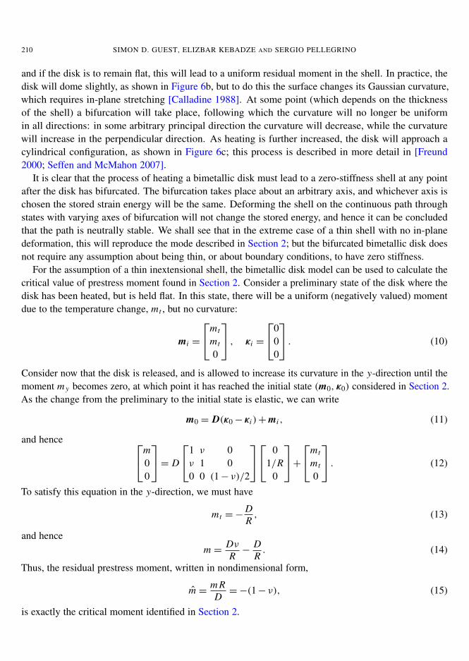
and if the disk is to remain flat, this will lead to a uniform residual moment in the shell. In practice, thedisk will dome slightly, as shown in Figure 6b, but to do this the surface changes its Gaussian curvature,which requires in-plane stretching [Calladine 1988]. At some point (which depends on the thicknessof the shell) a bifurcation will take place, following which the curvature will no longer be uniformin all directions: in some arbitrary principal direction the curvature will decrease, while the curvaturewill increase in the perpendicular direction. As heating is further increased, the disk will approach acylindrical configuration, as shown in Figure 6c; this process is described in more detail in [Freund2000; Seffen and McMahon 2007].
It is clear that the process of heating a bimetallic disk must lead to a zero-stiffness shell at any pointafter the disk has bifurcated. The bifurcation takes place about an arbitrary axis, and whichever axis ischosen the stored strain energy will be the same. Deforming the shell on the continuous path throughstates with varying axes of bifurcation will not change the stored energy, and hence it can be concludedthat the path is neutrally stable. We shall see that in the extreme case of a thin shell with no in-planedeformation, this will reproduce the mode described in Section 2; but the bifurcated bimetallic disk doesnot require any assumption about being thin, or about boundary conditions, to have zero stiffness.
For the assumption of a thin inextensional shell, the bimetallic disk model can be used to calculate thecritical value of prestress moment found in Section 2. Consider a preliminary state of the disk where thedisk has been heated, but is held flat. In this state, there will be a uniform (negatively valued) momentdue to the temperature change, mt , but no curvature:
mi =
mt
mt
0
, κi =
000
. (10)
Consider now that the disk is released, and is allowed to increase its curvature in the y-direction until themoment m y becomes zero, at which point it has reached the initial state (m0, κ0) considered in Section 2.As the change from the preliminary to the initial state is elastic, we can write
m0 = D(κ0− κi )+mi , (11)
and hence m00
= D
1 ν 0ν 1 00 0 (1− ν)/2
01/R
0
+mt
mt
0
. (12)
To satisfy this equation in the y-direction, we must have
mt =−DR, (13)
and hencem = Dν
R−
DR. (14)
Thus, the residual prestress moment, written in nondimensional form,
m = m RD=−(1− ν), (15)
is exactly the critical moment identified in Section 2.
A ZERO-STIFFNESS ELASTIC SHELL STRUCTURE 211
5. Conclusion
The disk model presented in Section 4 has shown that the zero-stiffness mode identified in Section 2can be explained simply by consideration of a hidden symmetry of the shell structure: if the structure isflattened, then the resultant moment in the shell doesn’t vary with direction, and bending about any axisis equally preferable. There may be minor effects associated with boundary conditions, but these didn’thave a noticeable effect on the experimental structures that we manufactured, and they will certainly notbe present for a circular shell structure.
Acknowledgements
This research was sponsored by the EPSRC (research grant GR/M72852/01) and supported by RolatubeTechnology Ltd. Guest acknowledges support from the Leverhulme Trust.
References
[Calladine 1978] C. R. Calladine, “Buckminster Fuller’s “Tensegrity” structures and Clerk Maxwell’s rules for the constructionof stiff frames”, Int. J. Solids Struct. 14:2 (1978), 161–172.
[Calladine 1988] C. R. Calladine, Theory of shell structures, Cambridge University Press, 1988.
[Freund 2000] L. B. Freund, “Substrate curvature due to thin film mismatch strain in the nonlinear deformation range”, J. Mech.Phys. Solids 48:6-7 (2000), 1159–1174.
[Galletly and Guest 2004] D. A. Galletly and S. D. Guest, “Bistable composite slit tubes, II: a shell model”, Int. J. Solids Struct.41:16–17 (2004), 4503–4516.
[Guest 2011] S. D. Guest, “The stiffness of tensegrity structures”, IMA J. Appl. Math. 76:1 (2011), 57–66.
[Guest and Pellegrino 2006] S. D. Guest and S. Pellegrino, “Analytical models for bistable cylindrical shells”, Proc. R. Soc.Lond. A 462:2067 (2006), 839–854.
[Kebadze et al. 2004] E. Kebadze, S. D. Guest, and S. Pellegrino, “Bistable prestressed shell structures”, Int. J. Solids Struct.41:11-12 (2004), 2801–2820.
[Mansfield 1973] E. H. Mansfield, “Large-deflexion torsion and flexure of initially curved strips”, Proc. R. Soc. Lond. A334:1598 (1973), 279–298.
[Pellegrino 2005] S. Pellegrino, “Bistable shell structures”, in 46th AIAA/ASME/ASCE/AHS/ASC Structures, Structural Dy-namics, and Materials Conference (Austin, TX, 2005), AIAA, Reston, VA, 2005.
[Rimrott 1965] F. P. J. Rimrott, “Storable tubular extendible member: a unique machine element”, Mach. Des. 37 (1965),156–163.
[Schenk et al. 2007] M. Schenk, S. D. Guest, and J. L. Herder, “Zero stiffness tensegrity structures”, Int. J. Solids Struct. 44:20(2007), 6569–6583.
[Seffen and McMahon 2007] K. A. Seffen and R. A. McMahon, “Heating of a uniform wafer disk”, Int. J. Mech. Sci. 49:2(2007), 230–238.
[Seffen and Pellegrino 1999] K. A. Seffen and S. Pellegrino, “Deployment dynamics of tape springs”, Proc. R. Soc. Lond. A455:1983 (1999), 1003–1048.
[Tarnai 2003] T. Tarnai, “Zero stiffness elastic structures”, Int. J. Mech. Sci. 45:3 (2003), 425–431.
Received 17 May 2010. Revised 4 Aug 2010. Accepted 4 Aug 2010.
SIMON D. GUEST: [email protected] of Engineering, University of Cambridge, Trumpington Street, Cambridge CB2 1PZ, United Kingdomhttp://www.eng.cam.ac.uk/~sdg

212 SIMON D. GUEST, ELIZBAR KEBADZE AND SERGIO PELLEGRINO
ELIZBAR KEBADZE: [email protected] of Engineering, University of Cambridge, Trumpington Street, Cambridge CB2 1PZ, United KingdomCurrent address: BP Exploration, Chertsey Road, Sunbury-upon-Thames, TW16 7LN, Middlesex, United Kingdom
SERGIO PELLEGRINO: [email protected] Aerospace Laboratories, California Institute of Technology, Pasadena, CA 91125, United Stateshttp://www.pellegrino.caltech.edu
mathematical sciences publishers msp