journal of hydrology - - get a free blog here
TRANSCRIPT
Journal of Hydrology 406 (2011) 170–181
Contents lists available at ScienceDirect
Journal of Hydrology
journal homepage: www.elsevier .com/locate / jhydrol
Large scale hydrologic and hydrodynamic modeling using limited dataand a GIS based approach
Rodrigo C.D. Paiva ⇑, Walter Collischonn, Carlos E.M. TucciInstituto de Pesquisas Hidráulicas – IPH, Universidade Federal do Rio Grande do Sul – UFRGS, Av. Bento Gonçalves, 9500 – Porto Alegre, 90050-260 RS, Brazil
a r t i c l e i n f o
Article history:Received 5 October 2010Received in revised form 6 June 2011Accepted 12 June 2011Available online 25 June 2011This manuscript was handled by K.Georgakakos, Editor-in-Chief, with theassistance of Enrique R. Vivoni, AssociateEditor
Keywords:Large scale hydrodynamic modelAmazonFlow routingFlood inundationSTRM DEMGIS algorithm
0022-1694/$ - see front matter � 2011 Elsevier B.V. Adoi:10.1016/j.jhydrol.2011.06.007
⇑ Corresponding author. Tel.: +55 5133087511.E-mail addresses: [email protected] (
iph.ufrgs.br (W. Collischonn), [email protected] (C.E.M
s u m m a r y
In this paper, we present a large-scale hydrologic model with a full one-dimensional hydrodynamic mod-ule to calculate flow propagation on a complex river network. The model uses the full Saint–Venant equa-tions and a simple floodplain storage model, and therefore is capable of simulating a wide range of fluvialprocesses such as flood wave delay and attenuation, backwater effects, flood inundation and its effects onflood waves. We present the model basic equations and GIS algorithms to extract model parameters fromrelatively limited data, which is globally available, such as the SRTM DEM. GIS based algorithms includethe estimation of river width and depth using geomorphological relations, river cross section bottomlevel and floodplain geometry extracted from DEM, etc. We also show a case study on one of the majortributaries of the Amazon, the Purus River basin. A model validation using discharge and water level datashows that the model is capable of reproducing the main hydrological features of the Purus River basin.Also, realistic floodplain inundation maps were derived from the results of the model. Our main conclu-sion is that it is possible to employ full hydrodynamic models within large-scale hydrological modelseven using limited data for river geometry and floodplain characterization.
� 2011 Elsevier B.V. All rights reserved.
1. Introduction
Large-scale hydrological models have been used for the impactassessment of land use change (e.g. Matheussen et al., 2000) andclimate change (e.g. Nijssen et al., 2001; Xu et al., 2005) on waterresources, for the study of hydrobiogeochemical processes (e.g. Fo-ley et al., 1996; Zhang et al., 2002), as a basis for hydrological fore-cast systems (e.g. Wood et al., 2002; Collischonn et al., 2005;Thielen et al., 2009) and also as the land surface component of cli-mate models (Pitman, 2003; Wood et al., 1992; Liang et al., 1994).These models are in constant development, partly as a conse-quence of a growing understanding of the hydrological processes,partly due to increasing computational capacity, and also due tothe growing availability of remote sensing data sources (Schmuggeet al., 2002), such as energy fluxes estimates (Bastiaanssen et al.,1998) and river water level (Frappart et al., 2006; Getirana et al.,2010).
Most of the large-scale hydrological models are conceptualmodels having at least a small physical basis. Some of them tryto represent the role of different vegetation and soil types on thestreamflow generation processes and on water and energy budgets
ll rights reserved.
R.C.D. Paiva), collischonn@. Tucci).
of the basin. These features can be found in such models as VIC(Liang et al., 1994), LASCAM (Viney et al., 2000), TOPKAPI model(Liu and Todini, 2002), and IBIS–THMB (Coe et al., 2007). However,one key aspect in the behavior of large-scale river basins that hasbeen partially neglected in this generation of large-scale hydrolog-ical models is river hydrodynamics.
Large-scale hydrological models usually use simple flow routingmodels that focus only on the flood wave delay and attenuation,such as storage or linear reservoir based models (Coe, 2000,1997; Arora, 2001; Liston et al., 1994; Decharme et al., 2008), lin-earized Saint–Venant equations representing wave advection anddiffusion (Lohmann et al., 1996), kinematic wave approximations(Liu and Todini, 2002; De Roo et al., 2000), or the Muskingum–Cun-ge model (Collischonn et al., 2007) and its variations (Beighleyet al., 2009; Todini, 2007; Koussis, 2009).
While these simplified flow routing methods can in principleadequately represent flood wave delay and attenuation, they can-not deal with some of the hydrodynamic processes that are oftenpresent in large-scale river systems, notably backwater and flood-plain storage effects. This is the case in the Amazon basin, whereflow of several rivers is controlled by backwater effects, as reportedby Meade et al. (1991), Trigg et al. (2009) and Tomasella et al.(2010), and the floodplains are a significant component of the flu-vial system (Bonnet et al., 2008). Floodplains also play an impor-tant role in many other South American river basins (Hamilton
R.C.D. Paiva et al. / Journal of Hydrology 406 (2011) 170–181 171
et al., 2002), in the transport of dissolved and particulate materials(e.g. Bourgoin et al., 2007), in biogeochemical processes and in theglobal carbon cycle (Richey et al., 2002; Zhang et al., 2002). Flood-plains may also influence feedback effects between land surfaceand atmosphere (Mohamed et al., 2005; Collini et al., 2008; Bettset al., 1996; Silva Dias et al., 2004). The explicit simulation of floodinundation could provide the basis for the representation of allthese processes.
Hydrodynamic flow routing in large-scale hydrological modelscould also provide results of other flow related variables, such asriver stage, velocity and slope. These models could also be usedas a basis for transport models by solving the advection–diffusionequation and sediment transport equations.
One dimensional (1D) hydrodynamic river models are welldeveloped since the late 1970s (Cunge et al., 1980), and there areeven well known packages for 1D hydrodynamic modeling (USACE,2002; DHI, 2003). These models have been applied in relativelylarge-scale problems (Paz et al., 2010; Remo and Pinter, 2007;Biancamaria et al., 2009; Lian et al., 2007), however their use with-in large-scale distributed hydrological models, which also repre-sent rainfall-runoff processes, is uncommon. There are alsoapproaches for flood inundation simulation ranging from simpli-fied models such as a composite cross section (Cunge et al.,1980) to 2D models (Galland et al., 1991; Bates and De Roo, 2000).
The reason why simple flow routing methods are still preferredwithin large-scale hydrological models is probably related to thelower input data needs and the lower computational burden theyimpose, while still providing reasonable results in several cases.Hydrodynamic river models need river cross section data that areusually surveyed only for relatively short reaches. Hydrodynamicmodels are also more computational intensive than simplified flowrouting methods, and require more detailed information on bound-ary and initial conditions.
However, computing capacity keeps growing, and also new andhigher accuracy remote sensing data such as the Digital ElevationModel (DEM) from the Shuttle Radar Topography Mission (SRTM)(Rabus et al., 2003; Farr et al., 2007) can be used to provide someof the information that is needed to compute parameters for largescale hydrodynamic models. In a recent example, Trigg et al. (2009)showed that the use of a simplified bathymetry, i.e. a wide rectan-gular channel approximation and a simple bed slope, does notintroduce significant errors in the hydrodynamic simulation re-sults in part of the central Amazon.
In the present paper, we describe the development of a modelfor large scale hydrologic and hydrodynamic modeling. The modeluses limited data that can be usually found in global scale for mostriver basins, mainly SRTM DEM. GIS methods are used to extractthe needed information from SRTM DEM. The proposed model isbasically an improvement of the MGB-IPH large scale hydrologicalmodel (Collischonn et al., 2007). First, a brief description of theMGB-IPH hydrological model is presented (Section 2). Later, detailsconcerning the hydrodynamic model equations, then a representa-tion of the floodplains and the numerical scheme are shown (Sec-tion 3). We also present the GIS based algorithms developed toextract the hydrodynamic model parameters from the DEM (Sec-tion 4) and a simple approach for 2D flood inundation simulation(Section 5). The model is tested in a case study of the river Purus,one of the major tributaries of the Amazon (Section 6). Other re-sults for an even larger region, and comparisons with simplifiedflow routing methods are presented by Paiva et al. (in review).
2. The hydrological model
The MGB-IPH model (‘‘Modelo Hidrológico de Grandes Bacias’’)is a large scale distributed hydrological model. It is similar to other
large scale hydrological models such as LARSIM (Ludwig andBremicker, 2006) and VIC (Liang et al., 1994; Nijssem et al.,1997). It is a process based model that uses physical and concep-tual equations to simulate the terrestrial hydrological cycle: soilwater budget, energy budget and evapotranspiration, interception,superficial, sub-superficial and groundwater flow generation androuting and river flow routing. It uses a daily or hourly simulationtime step.
The early version of the MGB-IPH model was based on a squarecell discretization of the river basin (Collischonn et al., 2007), whilethe version described in the present paper uses a division of the ba-sin in small catchments using the ArcHydro methods (Maidment,2002). Each catchment is subdivided into Hydrological ResponseUnits (HRUs) which are areas with similar hydrological behaviorand defined by a combination of soil and land cover maps (Beven,2001; Kouwen et al., 1993). Vertical water and energy budgets arecomputed independently for each HRU in each catchment. Canopyinterception is represented by a reservoir with maximum storageas a function of vegetation leaf area index. Soil water budget iscomputed simulating the soil as a single water reservoir. Soil infil-tration and runoff are computed based on the variable contributingarea concept of the ARNO model (Todini, 1996), which is also usedin the PDM (Moore and Clarke, 1981), VIC2L and LARSIM models.Energy budget is computed using basic surface meteorologicalvariables and evapotranspiration from soil, vegetation and canopyinto the atmosphere is estimated based on the Penman Monteithapproach (Monteith, 1965; Shuttleworth, 1993; Allen et al.,1998). Subsurface flow is computed using an equation similar tothe Brooks and Corey unsaturated hydraulic conductivity equation(Rawls et al., 1993). Percolation from soil layer to groundwater iscalculated according to a simple linear relation between soil waterstorage and maximum soil water storage. Then, the flow generatedwithin each catchment is routed to the stream network using threelinear reservoirs (base flow, subsurface flow and surface flow). Adetailed description of the model is given by Collischonn et al.(2007), and recent applications of the model are presented by Get-irana et al. (2010), Collischonn et al. (2008), and Collischonn et al.(2005).
Until now, river flow routing within the MGB-IPH model used tobe calculated using the Muskingum Cunge method, but in this pa-per we describe a mixed method, which employs a hydrodynamicmodel in flat reaches of the main rivers and the Muskingum–Cungemethod in the headwater parts of the drainage network, whereslope is usually higher.
3. The hydrodynamic model
The hydrodynamic model is based on the IPH-IV model, firstdeveloped by Tucci (1978). The model solves the full Saint Venantequations (Cunge et al., 1980):
@Q@xþ b
@h@t¼ qcat � qfl ð1Þ
@Q@tþ 2v @Q
@xþ ðgA� v2bÞ @h
@x� v2@A
@x
����h¼cte
¼ gAðS0 � Sf Þ ð2Þ
where the first and second equations are the 1D channel mass andmomentum conservation laws, Q (m3 s�1) is river discharge, t (s) istime, x (m) is river longitudinal space coordinate, b (m) is river crosssection width at free surface elevation, qcat (m2 s�1) is local catch-ment lateral inflow (the sum of the surface, subsurface and baseflow from the catchment), qfl (m2 s�1) is the river-floodplain flowexchange, h (m) is water depth, v (m s�1) is flow velocity averagedover the cross section, g (m s�2) is acceleration due to gravity, A(m2) is the cross sectional flow area perpendicular to the flow direc-tion and S0 (m m�1) and Sf (m m�1) are the bed slope and friction
172 R.C.D. Paiva et al. / Journal of Hydrology 406 (2011) 170–181
slope in the x-direction. Friction slope is estimated using Manning’sequation. Flow at river confluences is modeled using a simple masscontinuity equation and the energy equation discarding energylosses and the kinetic term (Cunge et al., 1980). It is also possibleto model hydraulic river singularities such as dams or other hydrau-lic structures using internal boundary conditions.
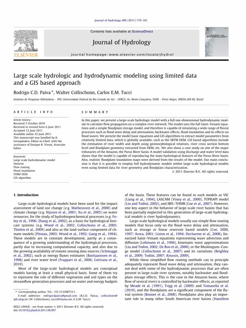
The river reaches are discretized into several river cross sections(Fig. 1) where the hydraulic variables are computed. The modelalso divides the catchments into floodplain units (Fig. 1). Theseare areas between two river cross sections where the river-floodplain flow exchange and floodplain water storage arecomputed.
Flood inundation is simulated using a simple storage model(Cunge et al., 1980), which assumes that (i) the flow velocity par-allel to the river direction is null on floodplains, (ii) the floodplainunits act only as storage areas and (iii) the floodplain water levelequals the water level at the main channel. Considering the modelbasic assumptions and the mass conservation law, theriver-floodplain flow exchange qfl equals:
qfl ¼AflðzÞ
dx@h@t¼ LðzÞ @h
@tð3Þ
where Afl (m2) is the flooded area and L (m) is the floodplain equiv-alent width, measured for each floodplain unit, as described inSection 4.5.
This is a simplistic approach that cannot fully represent all as-pects of floodplain hydrodynamics such as floodplain water levelsthat are not equal to the adjacent main channel, floodplain flowssubparallel to the main river channel, and bidirectional floodplainflows, that where observed by Alsdorf et al. (2007) using remotesensing data in the Amazon. Additionally, as observed by Alsdorfet al. (2003), water level changes in the main channel may not in-stantly propagate across the entire floodplain, as is implicitly con-sidered in the model described here. However, the proposedmodel, which is relatively complex in terms of river hydraulics,but somewhat simplified in terms of floodplain simulation, maybe appropriate because (i) this model is oriented to large scaleapplications and aimed at providing discharge, water level andflood extent results, by simulating translation and diffusion offlood waves, backwater effects and the influence of floodplain stor-age on flood waves, (ii) it is not oriented for studying smaller scalefloodplain hydraulics, (iii) it is compatible with large scale applica-
Fig. 1. Model discretization into catchments (grey lines), river reaches (black lines),river cross sections (grey dots) and floodplain units (grey thin lines).
tions, different from complex floodplain models which requirehigher computational resources and detailed floodplain bathyme-try data, that cannot be provided by current global scale DEMsand (iv) it is in accordance with Trigg et al. (2009), who stated that‘‘it is important to get the hydraulics of the main channel right be-fore tackling the more complex interactions with the floodplain’’.
The partial differential equations of the model are solved usinga linear and implicit finite difference numerical scheme developedby Chen (1973), similar to the Preissman scheme (Cunge et al.,1980). Since the model simulates a river network with lots of con-fluences, the set of discretized equations forms a non symmetricsparse linear system. Then, for better computational efficiency,the matrix solver uses a modified Gauss elimination procedurebased on a skyline storage method, avoiding the storage of null ele-ments of the linear system of equations. This method was devel-oped by Tucci (1978) and is similar to methods used by HEC-RAS(USACE, 2002). In addition, a modification to the method devel-oped by Tucci (1978) is proposed. An additional pointer is set inthe beginning of the simulation to store only algebraic operationsthat are actually needed for the Gauss elimination algorithm, i.e.it avoids operations with null elements, and then computes onlythose during the rest of the simulation. This improvement in-creased the speed of calculations but it will not be fully describedhere.
4. GIS based algorithms
Any hydrodynamic model should be applied using data fromdetailed surveys of river cross sections and, when necessary, flood-plain extent. This kind of data is usually available only at smallscale, for relatively short river reaches. For large scale hydrologicmodeling the necessary information has to be derived from glob-ally available data sets.
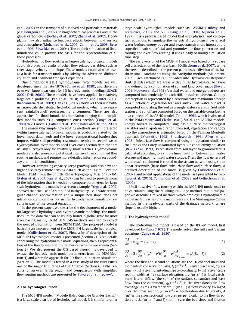
In our case, which is focused on applications of the model inlarge river basins, most of the necessary data is extracted from Dig-ital Elevation Models (DEM) (e.g. the SRTM DEM described in Ra-bus et al., 2003; Farr et al., 2007) and some GIS algorithms. Thealgorithms use a raster representation of topography and all otherspatial variables. The spatial variables are described through matri-ces of r rows and c columns, which store gridded values in r � cpositions defined as pixels. The pixel hi, ji corresponds to the ele-ment of a matrix located at row i and column j. The Digital Eleva-tion Model is denoted by Z hi, ji and provides the terrain elevationin each point hi, ji. The algorithms for model parameter extractioninclude, as presented in Fig. 2, (1) DEM preprocessing, (2) river net-work and catchment discretization, (3) river cross section discret-ization, location and topology, (4) river cross section geometry, (5)river cross section bottom level, (6) floodplain geometry. Theseprocedures are presented in the following sections. Examples of re-sults from these algorithms are presented in Section 6.3.
4.1. DEM preprocessing and catchment discretization
DEM preprocessing and the river and catchment discretizationalgorithms presented in this section are computed using wellknown algorithms as presented in Jenson and Domingue (1988)and available in several GIS packages such as the ArcHydro tools(Maidment, 2002).
The DEM preprocessing algorithms include first the computa-tion of the flow direction dhi, ji raster. Flow direction is a functionof DEM that returns the direction of the largest slope (N, NE, E,SE, S, SW, W, NW or null). Given the flow direction, the coordinatesof the downstream pixel hydrologically connected to hi, ji are givenby the function F:
Fhi; ji ¼ hi; ji þ Dðdhi; jiÞ ð4Þ

Flow direc�onand DEM pitremoval
DEM
Flowaccumula�on
Drainage
River andcatchment
discre�sa�on
Cross sec�ondiscre�sa�on
Cross sec�ongeometry
River profileand crosssec�on
bo�om level
Floodplaingeometry
DEM
prep
rocessing
Inpu
tdata
Hydrological
mod
elinpu
t
Hydrodyna
mic
mod
elinpu
t
Fig. 2. Flow chart of GIS based algorithms.
R.C.D. Paiva et al. / Journal of Hydrology 406 (2011) 170–181 173
considering D(dhi, ji) a function that returns the relative positionhDi, Dji of the downstream pixel (e.g. D(N) = h+1, +1i orD(NE) = h+1, �1i). The flow direction algorithm also includes the re-moval of pits from the DEM to ensure hydrological continuity (Jen-son and Domingue, 1988). The next step is the computation of theflow accumulation raster A hi, ji, that returns for each pixel h i , j i,the sum of the surface area of all upstream pixels (Burrough andMcDonnell, 1998).
Later, using the flow direction and flow accumulation results,the river and catchment discretization is performed. The drainageD hi, ji maps the river network on pixels with flow accumulationA hi, ji larger than a threshold Amin (Burrough and McDonnel,1998). Then, the river network is segmented into several riverreaches, defined by river segments between upstream and down-stream confluences (or between a confluence and a river source)and each river reach gets a different code. Finally, catchment dis-cretization is performed by identifying pixels located upstream ofeach river reach and the result is the catchment raster B hi, ji. Foreach pixel hi, ji, the algorithms follow downstream the flow pathdefined by the flow direction using the function F until it finds ariver reach and assigns B hi, ji equal to the river reach code (Maid-ment, 2002).
4.2. Cross section discretization
A river reach within a catchment is then subdivided in severalshorter sub-reaches, as shown in Fig. 1. These sub-reaches are lim-ited by the positioning of model river cross-sections, wherehydraulic variables Q and h are computed. For a given river reachp, the number of cross sections is defined as np = Lp/Dxp + 1, whereDxp is the distance between two cross sections and L is the lengthof the reach p. A predefined value of the distance Dx between thecross sections is defined considering the spatial scale of interestand the performance of the numerical scheme of the hydrody-namic model (Cunge et al., 1980) and can be estimated a prioriconsidering recommendations such as Dx < cT/M as presented inCastellarin et al. (2009), where. c = (gh)0.5 is the flood wave celerity,T is the period of the flood wave and 30 < M < 50.
Then, the location of model cross sections is defined by dividingthe river reach in a number of sub-reaches that results in the sub-reach length (Dxp) as close as possible to a predefined value. The
algorithm starts from any pixel of the reach p and then follows up-stream the river flow path using the flow direction raster, thedrainage raster and the inverse of the function F (Eq. (4)) until itfinds the upstream extreme of the reach. The coordinates of thefirst cross section of the reach p equals this current position. Thenit sets the coordinates of the second cross section (m = 2) byrepeating the following steps: (1) follow the reach flow path down-stream using Eq. (4) and compute the accumulated distance x fromthe first cross section; (2) when x P (m � 1). Dxp for the first time,set the coordinates of the mth cross section equal to the currentposition; (3) set m = m + 1 to compute the next cross section andrepeat steps 1–3.
4.3. Cross section geometry
River cross sections are represented by a rectangular shape,with width B (m) and maximum depth H (m). Parameters B andH are estimated trough geomorphologic equations of the typeH = a � Ab
d, where a and b are parameters and Ad is the upstreamdrainage area. This kind of approach is used in several large scalesimplified flow routing algorithms, such as Coe et al. (2007), Arora(2001) or Decharme et al. (2008). The parameters used in the casestudy are presented in Section 6.3.
4.4. Cross section bottom level
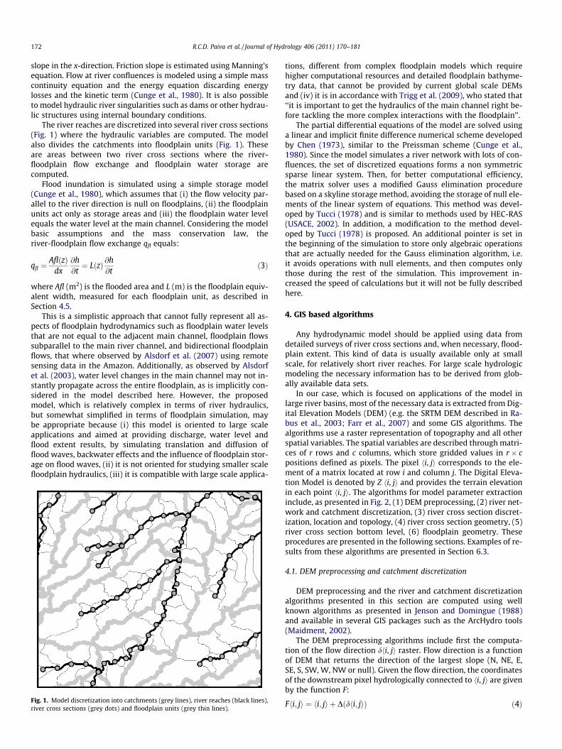
This section describes the procedure for estimating cross sec-tion bottom levels. This procedure takes three steps: (i) first a riverlongitudinal profile is extracted from the DEM for each river reach.Then, two corrections are applied to this longitudinal profile: (ii)removal of effects of vegetation and water depth and (iii) removalof random noise using an iterative moving average filter. The de-tails of these procedures are described below.
A river longitudinal profile is extracted from the DEM for eachreach to estimate river bottom level of computational cross sec-tions. The algorithm follows the reach path from upstream todownstream as described in Section 4.2 and computes terrain ele-vation zDEM as a function of distance x from the beginning of thereach:
zDEMðxÞ ¼ Zhi; ji ð5Þ
The elevations of the river longitudinal profile extracted fromSRTM DEM are not equal to river bottom level z0(x) (m). Systematicerrors related to vegetation, surface water effects and also randomerror related to noise on DEM data (Rabus et al., 2003; Sun et al.,2003; Farr et al., 2007; Kellndorfer et al., 2004; Lehner et al.,2006) affect the SRTM DEM elevation, which we call zDEM(x). Weconsider that the river bottom level z0(x) can be estimated usingthe following equation:
z0ðxÞ ¼ zDEMðxÞ � HðxÞ � HvegðxÞ � eðxÞ ð6Þ
where H (m) is the water depth, Hveg (m) is the effective vegetationheight (different from real vegetation height since SRTM C-band ra-dar penetrates the canopy to some extent) and e (m) is a randomnoise, as illustrated in Figs. 3 and 4.
The effective vegetation height Hveg is expected to depend onthe actual vegetation height, and on the ratio between river widthB (m) and DEM spatial resolution res (m). For different relations be-tween river width and DEM resolution, DEM elevation may beclose to the actual water stage or more perturbed by vegetationheight, as shown in Fig. 4. In large rivers, the elevation obtainedfrom SRTM data is close to water level. In narrow rivers, zDEM isclose to the elevation of the vegetation canopy, which covers theriver. Considering this, a preliminary longitudinal profile of bottomlevels z0 is estimated by:
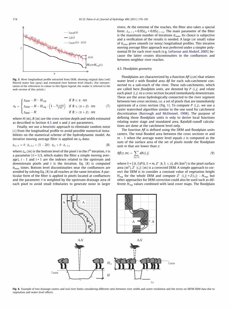
Fig. 3. River longitudinal profile extracted from DEM, showing original data (red)filtered water line (grey) and estimated river bottom level (black). (For interpre-tation of the references to colour in this figure legend, the reader is referred to theweb version of this article.)
174 R.C.D. Paiva et al. / Journal of Hydrology 406 (2011) 170–181
z0 ¼
zDEM � H � Hveg if B 6 a � res
zDEM � H � Hveg � 1� B�a�resb�res
� �if B 6 ðaþ bÞ � res
zMDE � H if B > ðaþ bÞ � res
8>><>>:
ð7Þ
where H (m), B (m) are the cross section depth and width estimatedas described in Section 4.3 and a and b are parameters.
Finally, we use a heuristic approach to eliminate random noise(e) from the longitudinal profile to avoid possible numerical insta-bilities on the numerical scheme of the hydrodynamic model. Aniterative moving average filter is applied on z0 data:
zi;tþ1 ¼ h � ziþ1;t þ ð1� 2hÞ � zi;t þ h � zi�1;t ð8Þ
where zi,t (m) is the bottom level of the pixel i in the tth iteration, h isa parameter (h = 1/3, which makes the filter a simple moving aver-age), i � 1 and i + 1 are the indexes related to the upstream anddownstream pixels and t is the iteration. Eq. (8) is computeditmax times. Bottom level discontinuities near the confluences areavoided by solving Eq. (8) in all reaches at the same iteration. A par-ticular form of the filter is applied in pixels located at confluencesand the parameter h is weighted by the upstream drainage area ofeach pixel to avoid small tributaries to generate noise in larger
AA’
H
Hve
zDEM
AA
Fig. 4. Example of two drainage rasters and real river limits considering different ratio bvegetation and water level effects.
rivers. At the extreme of the reaches, the filter also takes a specialform: zi,t + 1 = 0.95zi,t + 0.05zi + 1,t. The main parameter of the filteris the maximum number of iterations itmax. Its choice is subjectiveand a verification of the results is needed. A large (or small) valueof itmax gives smooth (or noisy) longitudinal profiles. This iterativemoving average filter approach was preferred under a simpler poly-nomial fit for each river reach (e.g. LeFavour and Alsdorf, 2005) be-cause the latter creates discontinuities in the confluences andbetween neighbor river reaches.
4.5. Floodplain geometry
Floodplains are characterized by a function Afl (z,m) that relateswater level z with flooded area Afl for each sub-catchment con-nected to a sub-reach of the river. These sub-catchments, whichare called here floodplain units, are denoted by P hi, ji and relateeach pixel hi, ji to a cross section located immediately downstream.These are the areas hydrologically connected to the river segmentbetween two cross sections, i.e. a set of pixels that are immediatelyupstream of a cross section (Fig. 1). To compute P hi, ji, we use araster watershed algorithm similar to the one used for catchmentdiscretization (Burrough and McDonnel, 1998). The purpose ofdefining those floodplain units is only to derive local functionsrelating water stage and inundated area. Rainfall-runoff calcula-tions are done at the catchment level only.
The function Afl is defined using the DEM and floodplain unitsrasters. The total flooded area between the cross sections m andm � 1 when the average water level equals z is computed as thesum of the surface area of the set of pixels inside the floodplainunit m that are lower than z:
Aflðz;mÞ ¼Xhi;ji2S
dAhi; ji ð9Þ
where S = {hk, li|Phk, li = m, Z� hk, li 6 z}, dA (km2) is the pixel surfacearea (m2), Z� hi, ji (m) is a corrected DEM. A simple approach to cor-rect the DEM is to consider a constant value of vegetation heightHveg for the whole DEM and compute Z� hi, ji = Zhi, ji � Hveg, butother approaches for DEM correction could also be used such as dif-ferent Hveg values combined with land cover maps. The floodplain
AA’
A
z0
zDEM
A
etween river width and raster resolution and the errors on SRTM DEM data due to
R.C.D. Paiva et al. / Journal of Hydrology 406 (2011) 170–181 175
equivalent width curve is computed as L(z, m) = Afl(z, m)/Dxm and acorrection is made L = max[0, L � B) to remove the main river width.
(a)
(b)
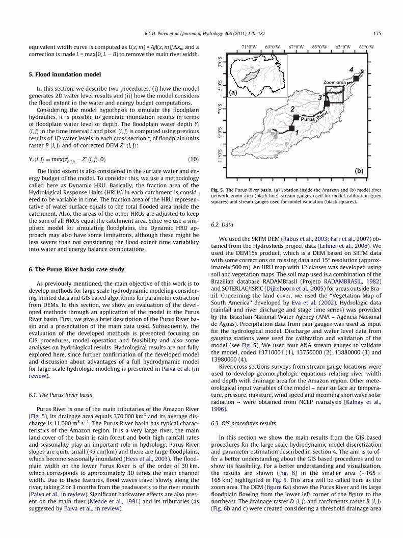
ig. 5. The Purus River basin. (a) Location inside the Amazon and (b) model riveretwork, zoom area (black line), stream gauges used for model calibration (greyquares) and stream gauges used for model validation (black squares).
5. Flood inundation model
In this section, we describe two procedures: (i) how the modelgenerates 2D water level results and (ii) how the model considersthe flood extent in the water and energy budget computations.
Considering the model hypothesis to simulate the floodplainhydraulics, it is possible to generate inundation results in termsof floodplain water level or depth. The floodplain water depth Yt
hi, ji in the time interval t and pixel hi, ji is computed using previousresults of 1D water levels in each cross section z, of floodplain unitsraster P hi, ji and of corrected DEM Z� hi, ji:
Ythi; ji ¼ maxðztPhi;ji � Z�hi; ji; 0Þ ð10Þ
The flood extent is also considered in the surface water and en-ergy budget of the model. To consider this, we use a methodologycalled here as Dynamic HRU. Basically, the fraction area of theHydrological Response Units (HRUs) in each catchment is consid-ered to be variable in time. The fraction area of the HRU represen-tative of water surface equals to the total flooded area inside thecatchment. Also, the areas of the other HRUs are adjusted to keepthe sum of all HRUs equal the catchment area. Since we use a sim-plistic model for simulating floodplains, the Dynamic HRU ap-proach may also have some limitations, although these might beless severe than not considering the flood extent time variabilityinto water and energy balance computations.
6. The Purus River basin case study
As previously mentioned, the main objective of this work is todevelop methods for large scale hydrodynamic modeling consider-ing limited data and GIS based algorithms for parameter extractionfrom DEMs. In this section, we show an evaluation of the devel-oped methods through an application of the model in the PurusRiver basin. First, we give a brief description of the Purus River ba-sin and a presentation of the main data used. Subsequently, theevaluation of the developed methods is presented focusing onGIS procedures, model operation and feasibility and also someanalyses on hydrological results. Hydrological results are not fullyexplored here, since further confirmation of the developed modeland discussion about advantages of a full hydrodynamic modelfor large scale hydrologic modeling is presented in Paiva et al. (inreview).
6.1. The Purus River basin
Purus River is one of the main tributaries of the Amazon River(Fig. 5), its drainage area equals 370,000 km2 and its average dis-charge is 11,000 m3 s�1. The Purus River basin has typical charac-teristics of the Amazon region. It is a very large river, the mainland cover of the basin is rain forest and both high rainfall ratesand seasonality play an important role in hydrology. Purus Riverslopes are quite small (<5 cm/km) and there are large floodplains,which become seasonally inundated (Hess et al., 2003). The flood-plain width on the lower Purus River is of the order of 30 km,which corresponds to approximately 30 times the main channelwidth. Due to these features, flood waves travel slowly along theriver, taking 2 or 3 months from the headwaters to the river mouth(Paiva et al., in review). Significant backwater effects are also pres-ent on the main river (Meade et al., 1991) and its tributaries (assuggested by Paiva et al., in review).
Fns
6.2. Data
We used the SRTM DEM (Rabus et al., 2003; Farr et al., 2007) ob-tained from the Hydrosheds project data (Lehner et al., 2006). Weused the DEM15s product, which is a DEM based on SRTM datawith some corrections on missing data and 1500 resolution (approx-imately 500 m). An HRU map with 12 classes was developed usingsoil and vegetation maps. The soil map used is a combination of theBrazilian database RADAMBrasil (Projeto RADAMBRASIL, 1982)and SOTERLAC/ISRIC (Dijkshoorn et al., 2005) for areas outside Bra-zil. Concerning the land cover, we used the ‘‘Vegetation Map ofSouth America’’ developed by Eva et al. (2002). Hydrologic data(rainfall and river discharge and stage time series) was providedby the Brazilian National Water Agency (ANA – Agência Nacionalde Águas). Precipitation data from rain gauges was used as inputfor the hydrological model. Discharge and water level data fromgauging stations were used for calibration and validation of themodel (see Fig. 5). We used four ANA stream gauges to validatethe model, coded 13710001 (1), 13750000 (2), 13880000 (3) and13980000 (4).
River cross sections surveys from stream gauge locations wereused to develop geomorphologic equations relating river widthand depth with drainage area for the Amazon region. Other mete-orological input variables of the model – near surface air tempera-ture, pressure, moisture, wind speed and incoming shortwave solarradiation – were obtained from NCEP reanalysis (Kalnay et al.,1996).
6.3. GIS procedures results
In this section we show the main results from the GIS basedprocedures for the large scale hydrodynamic model discretizationand parameter estimation described in Section 4. The aim is to of-fer a better understanding about the GIS based procedures and toshow its feasibility. For a better understanding and visualization,the results are shown (Fig. 6) in the smaller area (�165 �165 km) highlighted in Fig. 5. This area will be called here as thezoom area. The DEM (figure 6a) shows the Purus River and its largefloodplain flowing from the lower left corner of the figure to thenortheast. The drainage raster D hi, ji and catchments raster B hi, ji(Fig. 6b and c) were created considering a threshold drainage area
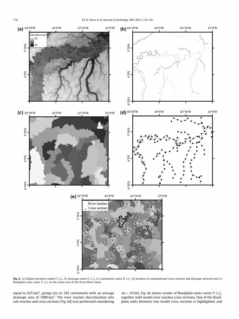
Fig. 6. (a) Digital elevation model Z hi, ji, (b) drainage raster D hi, ji, (c) catchments raster B hi, ji, (d) location of computational cross sections and drainage network and (e)floodplain units raster P hi, ji on the zoom area of the Purus River basin.
176 R.C.D. Paiva et al. / Journal of Hydrology 406 (2011) 170–181
equal to 625 km2, giving rise to 345 catchments with an averagedrainage area of 1000 km2. The river reaches discretization intosub-reaches and cross sections (Fig. 6d) was performed considering
Dx 6 10 km. Fig. 6e shows results of floodplain units raster P hi, ji,together with model river reaches cross sections. One of the flood-plain units between two model cross sections is highlighted, and
10 15 20 25 30 35 40 450
50
100
150
200
250
z [m]
Afl [
km2 ]
Fig. 7. Flooded area versus water level on the highlighted floodplain unit extractedfrom de DEM.
1300 1400 1500 1600 1700 1800
x [km]
z [k
m]
0
10
20
30
40
50
60
Fig. 8. Longitudinal profile of Purus River on the zoom area: DEM levels (zDEM) inblack line and estimated bottom levels (z0) with itmax = 50 (light grey line),itmax = 5000 (dark grey line) and itmax = 50,000 (bold black line).
Sep Oct Nov Dec Jan Feb Mar Apr May Jun Jul Aug Sep0
1
2
3
Fig. 9. Flood wave delay and attenuation in Purus River showed by the rationbetween daily and mean streamflow in the 1990/1991 hydrological year in thegauges 1 (grey line), 2 (black line) and 3 (dashed line) (see Fig. 5).
R.C.D. Paiva et al. / Journal of Hydrology 406 (2011) 170–181 177
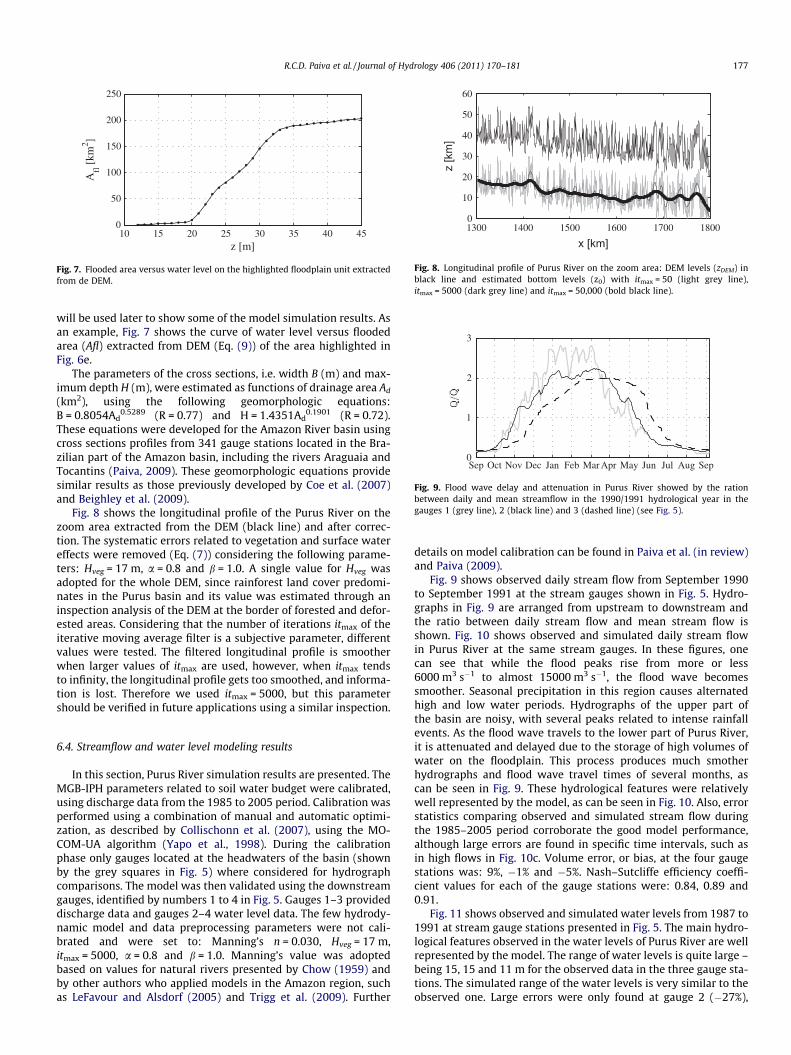
will be used later to show some of the model simulation results. Asan example, Fig. 7 shows the curve of water level versus floodedarea (Afl) extracted from DEM (Eq. (9)) of the area highlighted inFig. 6e.
The parameters of the cross sections, i.e. width B (m) and max-imum depth H (m), were estimated as functions of drainage area Ad
(km2), using the following geomorphologic equations:B = 0.8054Ad
0.5289 (R = 0.77) and H = 1.4351Ad0.1901 (R = 0.72).
These equations were developed for the Amazon River basin usingcross sections profiles from 341 gauge stations located in the Bra-zilian part of the Amazon basin, including the rivers Araguaia andTocantins (Paiva, 2009). These geomorphologic equations providesimilar results as those previously developed by Coe et al. (2007)and Beighley et al. (2009).
Fig. 8 shows the longitudinal profile of the Purus River on thezoom area extracted from the DEM (black line) and after correc-tion. The systematic errors related to vegetation and surface watereffects were removed (Eq. (7)) considering the following parame-ters: Hveg = 17 m, a = 0.8 and b = 1.0. A single value for Hveg wasadopted for the whole DEM, since rainforest land cover predomi-nates in the Purus basin and its value was estimated through aninspection analysis of the DEM at the border of forested and defor-ested areas. Considering that the number of iterations itmax of theiterative moving average filter is a subjective parameter, differentvalues were tested. The filtered longitudinal profile is smootherwhen larger values of itmax are used, however, when itmax tendsto infinity, the longitudinal profile gets too smoothed, and informa-tion is lost. Therefore we used itmax = 5000, but this parametershould be verified in future applications using a similar inspection.
6.4. Streamflow and water level modeling results
In this section, Purus River simulation results are presented. TheMGB-IPH parameters related to soil water budget were calibrated,using discharge data from the 1985 to 2005 period. Calibration wasperformed using a combination of manual and automatic optimi-zation, as described by Collischonn et al. (2007), using the MO-COM-UA algorithm (Yapo et al., 1998). During the calibrationphase only gauges located at the headwaters of the basin (shownby the grey squares in Fig. 5) where considered for hydrographcomparisons. The model was then validated using the downstreamgauges, identified by numbers 1 to 4 in Fig. 5. Gauges 1–3 provideddischarge data and gauges 2–4 water level data. The few hydrody-namic model and data preprocessing parameters were not cali-brated and were set to: Manning’s n = 0.030, Hveg = 17 m,itmax = 5000, a = 0.8 and b = 1.0. Manning’s value was adoptedbased on values for natural rivers presented by Chow (1959) andby other authors who applied models in the Amazon region, suchas LeFavour and Alsdorf (2005) and Trigg et al. (2009). Further
details on model calibration can be found in Paiva et al. (in review)and Paiva (2009).
Fig. 9 shows observed daily stream flow from September 1990to September 1991 at the stream gauges shown in Fig. 5. Hydro-graphs in Fig. 9 are arranged from upstream to downstream andthe ratio between daily stream flow and mean stream flow isshown. Fig. 10 shows observed and simulated daily stream flowin Purus River at the same stream gauges. In these figures, onecan see that while the flood peaks rise from more or less6000 m3 s�1 to almost 15000 m3 s�1, the flood wave becomessmoother. Seasonal precipitation in this region causes alternatedhigh and low water periods. Hydrographs of the upper part ofthe basin are noisy, with several peaks related to intense rainfallevents. As the flood wave travels to the lower part of Purus River,it is attenuated and delayed due to the storage of high volumes ofwater on the floodplain. This process produces much smotherhydrographs and flood wave travel times of several months, ascan be seen in Fig. 9. These hydrological features were relativelywell represented by the model, as can be seen in Fig. 10. Also, errorstatistics comparing observed and simulated stream flow duringthe 1985–2005 period corroborate the good model performance,although large errors are found in specific time intervals, such asin high flows in Fig. 10c. Volume error, or bias, at the four gaugestations was: 9%, �1% and �5%. Nash–Sutcliffe efficiency coeffi-cient values for each of the gauge stations were: 0.84, 0.89 and0.91.
Fig. 11 shows observed and simulated water levels from 1987 to1991 at stream gauge stations presented in Fig. 5. The main hydro-logical features observed in the water levels of Purus River are wellrepresented by the model. The range of water levels is quite large –being 15, 15 and 11 m for the observed data in the three gauge sta-tions. The simulated range of the water levels is very similar to theobserved one. Large errors were only found at gauge 2 (�27%),

1986 1987 1988 1989 1990 1991
Q [
m3 /
s]Q
[m
3 /s]
Q [
m3 /
s]
1986 1987 1988 1989 1990 1991
1986 1987 1988 1989 1990 1991
0
2000
4000
6000
8000
0
2000
4000
6000
8000
10000
12000
0
5000
10000
15000
(a)
(b)
(c)
Fig. 10. Observed (grey line) and simulated (black line) daily streamflow in thegauges 1 (a), 2 (b) and 3 (c) of Purus River in 1986–1991 time period (see Fig. 5).
1986 1987 1988 1989 1990 1991
y [m
]
1986 1987 1988 1989 1990 1991
y [m
]
1986 1987 1988 1989 1990 1991
y [m
]
-5
0
5
10
-5
0
5
-5
0
5
(a)
(b)
(c)
Fig. 11. Observed (grey line) and simulated (black line) daily water level in thegauges 2 (a), 3 (b) and 4 (c) of the Purus River in 1986–1991 time period (see Fig. 5).
178 R.C.D. Paiva et al. / Journal of Hydrology 406 (2011) 170–181
while at the other two gauges river stage amplitudes were cor-rectly reproduced (errors of �6% and �1%, respectively at gauges3 and 4). As in Fig. 10, water levels shown in Fig. 11 also illustratethe attenuation and delay of the flood wave due to floodplain stor-age as it travels through the Purus River. Analysis of the hydro-graphs and relatively high Nash–Sutcliffe efficiency coefficientvalues at those three gauges (0.84, 0.90 and 0.92) suggest thatthe model is performing good and that the delay and smoothingof the flood wave is being well represented by the propagationmodule of the hydrological model.
6.5. Simulated flood inundation dynamics
Based on model water level results maps of floodplain inunda-tion can be obtained by comparing water levels calculated athydrodynamic cross sections with DEM elevations, according tothe procedure presented in Section 5. In this section, we presentsome flood inundation results and discuss the potential of themodel in simulating different types of inundation dynamics.
Fig. 12 shows the simulated water depth on the floodplain atthree time intervals throughout the hydrological year 1995/1996(Fig. 12a–c). It also shows the computational river reaches andcross sections of the model. The first water depth map was derivedusing water levels calculated at the beginning of the hydrologicalyear, at low water season (15-October-1995), the second is fromthe high water season (22-April-1996) and the third is from thedeclining water level period (31-July-1996). Areas appearing whitein Fig. 12 are not flooded, while dark areas are flooded to depths of
several meters. It can be seen that the flooded areas expand fromthe dry to the wet season, and that floodplain areas located inthe downstream area (right part of Fig. 12) are still inundated afterthe passing of the flow peak.
Detailed results are given for one of the floodplain units, whichis highlighted in Fig. 12. For this floodplain unit we show time ser-ies of the flooded area Afl and exchange flux between river andfloodplain qfl, as calculated by the model (Fig. 13a). Fig. 13b showstime series of the main river discharge Q, again compared to qfl. Fi-nally, Fig. 13c shows water level z in the floodplain and its tempo-ral derivative dz/dt.
The inundation dynamics are characterized by a strong season-ality driven by the main river discharge and water level variations.According to model results, floodplain lateral exchange is driven bythe river water level variations. When the water level is rising(lowering), water flows from the main river (floodplain) to thefloodplain (main river) and the flooded area also increases(decreases).
Since one of the basic assumptions of the model is that there isno water level difference between the main river and the con-nected floodplain, total flooded area exhibits a similar behaviorof water levels. Also, the model assumes that all marginal lakesand other parts of the floodplain are fully connected to the river.This can be usually considered valid, since normally these marginallakes are connected to the main river through small channels (e.g.Bonnet et al., 2008).
Simulation results show that the majority of water in the flood-plain comes from the main river, and that inflow and outflow

Fig. 12. Simulated floodplain water depth on the zoom area of Purus River on 15-October-1995 (a), 22-April-1996 (b) and 31-July-1996 (c).
0
100
200
Afl [
km2 ]
1994 1995 1996 1997 1998 1999
1994 1995 1996 1997 1998 1999
1994 1995 1996 1997 1998 1999
-500
0
500
q fl [
m3 /s
]q fl
[m
3 /s]
0
1
2x 10
Q [
m3 /s
]
-500
0
500
15
20
25
30
35z
[m]
-0.2
-0.1
0
0.1
0.2
dz/d
t [m
/day
]
4
(a)
(b)
(c)
Fig. 13. (a) Simulated daily flooded area Afl (grey line) and floodplain lateralexchange qfl (black line), (b) simulated daily discharge Q (grey line) and floodplainlateral exchange qfl (black line) and (c) simulated daily water level z (grey line) andits temporal derivative dz/dt (black line) in a floodplain unit of Purus River for theperiod of 1994–1999.
R.C.D. Paiva et al. / Journal of Hydrology 406 (2011) 170–181 179
intensity is defined by variation in time of main river water level.Both features were reported by Bonnet et al. (2008) who analyzedinflow and outflow from a marginal lake of the Amazon River near
Óbidos using water level observations and modeling results. Simi-lar main river driven floodplain inundation dynamics were also ob-served by Alsdorf et al. (2010) in the mainstem Amazon floodplainusing gravimetric and imaging satellite methods.
In addition, inundation results of the model were validated interms of flooded areas extent (Paiva et al., in review; Paiva, 2009)and a good performance of the model was found.
It is worth noting that the model presented here is not able tosimulate a full 2D inundation dynamic, e.g. when two large riverscan exchange water trough floodplain flow. This situation may oc-cur in Amazon rivers, but it is not as common in this area as it is inthe Pantanal region (Paz et al., 2010), and probably it has relativelylow impact on large scale modeling results. To improve the repre-sentation of floodplain flow a 2D model should be more appropri-ate (Bates and De Roo, 2000; Bates et al., 2010). The modelpresented here only considers the floodplain storage in the 1Dhydrodynamic model, taking into account its effects on flood wavedelay and attenuation; and then we use the 1D water levels calcu-lated at cross section locations to generate 2D inundation maps.Although it has some limitations, the approach presented herecan be considered sufficient for large scale hydrological modelingand has much less computational demands.
180 R.C.D. Paiva et al. / Journal of Hydrology 406 (2011) 170–181
7. Conclusions
We describe the development of a model for large scale hydro-logic and hydrodynamic modeling. The proposed approach is suit-able for large scale applications in regions with limited data, sinceit uses regionalization methods and GIS algorithms that can be ap-plied using globally available datasets.
The model and methods used to derive the necessary informa-tion were tested in the Purus River basin, which is a representativepart of the Amazon basin in terms of river hydraulics and flood-plain abundance. The case study shows the feasibility of the GISbased algorithms for parameter extraction. A comparison betweenobserved and simulated discharges and water levels at gauging sta-tions shows that the model is capable of reproducing the mainhydrological features of the Purus River basin. Calibration ofparameters related to the hydrodynamic model was not necessary.However, while our modeling approach for flow propagation in riv-ers is relatively complex and complete, our description of flood-plain dynamics is very simple. Our approach does not fullyreproduce what is actually happening in the floodplains, neverthe-less realistic floodplain inundation maps were derived from the re-sults of the model. Our main concern is large scale applications andon the effects that floodplain inundation and emptying has on vari-ables measured at the river gauges.
Model errors may be related to input data, and limitations of themodel itself. In terms of the river flow propagation module, we be-lieve that errors may be related to the input data uncertainty, e.g.DEM precision and errors related to vegetation and cross sectiongeometry provided by geomorphologic relations. Nevertheless, re-sults show that it is possible to employ full hydrodynamic modelswithin large-scale hydrological modeling even using limited datafor river geometry and floodplain characterization. In comparisonto other large scale flow routing algorithms, the model can simu-late additional hydrological features such as backwater effectsand flood inundation dynamics and can provide other output vari-ables as river water levels, total flooded area and 2D water depth aswell.
In a forthcoming work (Paiva et al., in review), we present amodel validation including an evaluation of model errors and itssources. We evaluate its advantages if compared with simplifiedflow routing algorithms and also relate the differences in resultsfrom both techniques with the role played by the floodplains andbackwater effects.
Acknowledgements
The authors are grateful for the financial and operational sup-port from the Brazilian agencies FINEP and ANA as for constructivecomments of Marie-Paule Bonnet, Douglas Alsdorf, and anony-mous reviewers.
References
Allen, R.G., Pereira, L.S., Raes, D., Smith, M., 1998. Crop Evapotranspiration:Guidelines for Computing Crop Water Requirements. Irrigation and DrainagePaper 56. FAO, Rome.
Alsdorf, D., Dunne, T., Melack, J., Smith, L., Hess, L., 2003. Diffusion modeling ofrecessional flow on central Amazonian floodplains. Geophys. Res. Lett. 32,L21405.
Alsdorf, D., Bates, P., Melack, J., Wilson, M., Dunne, T., 2007. The spatial andtemporal complexity of the Amazon flood measured from space. Geophys. Res.Lett. 34, L08402.
Alsdorf, D., Han, S.-C., Bates, P., Melack, J., 2010. Seasonal water storage on theAmazon floodplain measured from satellites. Remote Sens. Environ. 114, 2448–2456.
Arora, V.K., 2001. Streamflow simulations for continental-scale river basins in aglobal atmospheric general circulation model. Adv. Water Resour. 24, 775–791.
Bastiaanssen, W.G.M., Menenti, M., Feddes, R.A., Holtslag, A.A.M., 1998. A remotesensing surface energy balance algorithm for land (SEBAL) 1. Formulation. J.Hydrol. 212–213, 198–212.
Bates, P.D., De Roo, A.P.J., 2000. A simple raster based model for flood inundationsimulation. J. Hydrol. 236, 54–77.
Bates, P.D., Horrit, M.S., Fewtrell, T.J., 2010. A simple inertial formulation of theshallow water equations for efficient two-dimensional flood inundationmodelling. J. Hydrol. 387, 33–45.
Beighley, R.E., Eggert, K.G., Dunne, T., He, Y., Gummadi, V., Verdin, K.L., 2009.Simulating hydrologic and hydraulic processes throughout the Amazon RiverBasin. Hydrol. Process. 23 (8), 1221–1235.
Betts, A.K., Ball, J.H., Beljaars, A.C.M., Miller, M.J., Viterbo, P.A., 1996. The landsurface–atmosphere interaction: a review based on observational and globalmodeling perspectives. J. Geophys. Res. 101 (D3), 7209–7225.
Beven, K.J., 2001. Rainfall-runoff Modeling: The Primer. Wiley, 360p.Biancamaria, S., Bates, P.D., Boone, A., Mognard, N.M., 2009. Large-scale coupled
hydrologic and hydraulic modelling of the Ob river in Siberia. J. Hydrol. 379,136–150.
Bonnet, M.P., Barroux, G., Martinez, J.M., Seyler, F., Turcq, P.M., Cochonneau, G.,Melack, J.M., Boaventura, G., Bourgoin, L.M., León, J.G., Roux, E., Calmant, S.,Kosuth, P., Guyot, J.L., Seyler, F., 2008. Floodplain hydrology in an Amazonfloodplain lake (Lago Grande de Curuaí). J. Hydrol. 349, 18–30.
Bourgoin, L.M., Bonnet, M.P., Martinez, J.M., Kosuth, P., Cochonneau, G., Turcq, P.M.,Guyot, J.L., Vauchel, P., Filizola, N., Seyler, P., 2007. Temporal dynamics of waterand sediment exchanges between the Curuaí floodplain and the Amazon River,Brazil. J. Hydrol. 335, 140–156.
Burrough, P.A., McDonnel, R.A., 1998. Principles of Geographical InformationSystems: Spatial Information Systems and Geostatistics. Oxford UniversityPress, Oxford, 333p.
Castellarin, A., Di Baldassarre, G., Bates, P.D., Brath, A., 2009. Optimal cross-sectionalspacing in Preissmann scheme 1D hydrodynamic models. Journal of HydraulicEngineering 135 (2), 96–105.
Chen, Y.H., 1973. Mathematical Modeling of Water and Sediment Routing in NaturalChannels. PhD Dissertation, Colorado State University, USA.
Chow, V.T., 1959. Open Channel Hydraulics. McGraw-Hill, 680p.Coe, M.T., 1997. Simulating continental surface waters: an application to holocene
Northern Africa. J. Clim. 10, 1680–1689.Coe, M.T., 2000. Modeling terrestrial hydrological systems at the continental scale:
testing the accuracy of an atmospheric GCM. J. Clim. 13, 686–704.Coe, M.T., Costa, M.H., Howard, E.A., 2007. Simulating the surface waters of the
Amazon River basin: impacts of new river geomorphic and flowparameterizations. Hydrol. Process. 22 (14), 2542–2553.
Collini, E.A., Berbery, E.H., Barros, V., Pyle, M., 2008. How does soil moisture influencethe early stages of the South American Monsoon? J. Clim. 21, 195–213.
Collischonn, W., Haas, R., Andreolli, I., Tucci, C.E.M., 2005. Forecasting river Uruguayflow using rainfall forecasts from a regional weather-prediction model. J.Hydrol. 305, 87–98.
Collischonn, W., Allasia, D.G., Silva, B.C., Tucci, C.E.M., 2007. The MGB-IPH model forlarge-scale rainfall-runoff modeling. J. Hydrol. Sci. 52, 878–895.
Collischonn, B., Collischonn, W., Tucci, C., 2008. Daily hydrological modeling in theAmazon basin using TRMM rainfall estimates. J. Hydrol. 360 (1–4), 207–216.
Cunge, J.A., Holly, F.M., Verwey, A., 1980. Practical Aspects of Computational RiverHydraulics. Pitman Advanced Publishing Program.
De Roo, A.P.J., Wesseling, C.G., Van Deursen, W.P.A., 2000. Physically based riverbasin modeling within GIS: the LISFLOOD model. Hydrol. Process. 14, 1984–1992.
Decharme, B., Douville, H., Prigent, C., Papa, F., Aires, F., 2008. A new river floodingscheme for global climate applications: off-line evaluation over South America.J. Geophys. Res. 113.
DHI, 2003. MIKE 11 – A Modelling System for Rivers and Channels – ReferenceManual. DHI Software.
Dijkshoorn, J.A., Huting, J.R.M., Tempel, P., 2005. Update of the 1:5 million Soil andTerrain Database for Latin America and the Caribbean (SOTERLAC, Version 2.0).Report 2005/01, ISRIC – World Soil Information, Wageningen.
Eva, H.D., De Miranda, E.E., Di Bella, C.M., Gond, V., 2002. A Vegetation Map of SouthAmerica. EUR 20159 EN, European Commission, Luxembourg.
Farr, T.G., Caro, E., Crippen, R., Duren, R., Hensley, S., Kobrick, M., Paller, M.,Rodriguez, E., Rosen, P., Roth, L., Seal, D., Shaffer, S., Shimada, J., Umland, J.,Werner, M., Burbank, D., Oskin, M., Alsdorf, D., 2007. The shuttle radartopography mission. Rev. Geophys. 45 (2).
Foley, J.A., Prentice, I.C., Ramankutty, N., Levis, S., Pollard, D., Sitch, S., Haxeltine, A.,1996. An integrated biosphere model of land surface processes, terrestrialcarbon balance, and vegetation dynamics. Global Biogeochem. Cycles 10 (4),603–628.
Frappart, F., Calmant, S., Cauhopé, M., Seyler, F., Cazenave, A., 2006. Preliminaryresults of ENVISAT RA-2-derived water levels validation over the Amazon basin.Remote Sens. Environ. 100, 252–264.
Galland, J.C., Goutal, N., Hervouet, J.M., 1991. TELEMAC – a new numerical model forsolving shallow-water equations. Adv. Water Resour. 14 (3), 138–148.
Getirana, A.C.V., Bonnet, M.-P., Rotunno Filho, O.C., Collischonn, W., Guyot, J.-L.,Seyler, F., Mansur, W.J., 2010. Hydrological modelling and water balance of theNegro River basin: evaluation based on in situ and spatial altimetry data.Hydrol. Process. doi:10.1002/hyp.7747.
Hamilton, S.K., Sippel, S.J., Melack, J.M., 2002. Comparison of inundation patternsamong major South American floodplains. J. Geophys. Res., 107(D20), LBA-1–LBA-4.
Hess, L.L., Melack, J.M., Novo, E.M.L.M., Barbosa, C.C.F., Gastil, M., 2003. Dual-seasonmapping of wetland inundation and vegetation for the central Amazon basin.Remote Sens. Environ. 87, 404–428.

R.C.D. Paiva et al. / Journal of Hydrology 406 (2011) 170–181 181
Jenson, S.K., Domingue, J.O., 1988. Extracting topographic structure from digitalelevation data for geographic information system analysis. PhotogrammetricEng. Remote Sens. 54 (11), 1593–1600.
Kalnay, E. et al., 1996. The NCEP/NCAR 40-years reanalysis project. Bull. Am.Meteorol. Soc. 77, 437–471.
Kellndorfer, J., Walker, W., Pierce, L., Dobson, C., Fites, J.A., Hunsaker, C., Vona, J.,Clutter, M., 2004. Vegetation height estimation from shuttle radar topographymission and national elevation datasets. Remote Sens. Environ. 93, 339–358.
Koussis, A.D., 2009. Assessment and review of the hydraulics of storage floodrouting 70 years after the presentation of the Muskingum method. Hydrol. Sci. J.54 (1).
Kouwen, N. et al., 1993. Grouping response units for distributed hydrologicmodelling. J. Water Resour. Manage. Planning 119 (3), 289–305.
LeFavour, G., Alsdorf, D., 2005. Water slope and discharge in the Amazon Riverestimated using the Shuttle Radar Topography Mission digital elevation model.Geophys. Res. Lett. 32, L17404.
Lehner, B., Verdin, K., Jarvis, A., 2006. HydroSHEDS Technical Documentation. WorldWiuldlife Fund US, Washington, DC. <http://hydrosheds.cr.usgs.gov>.
Lian, Y., Chan, I.-C., Singh, J., Demissie, M., Knapp, V., Xie, H., 2007. Coupling ofhydrologic and hydraulic models for the Illinois River Basin. J. Hydrol. 344, 210–222.
Liang, X., Lettenmaier, D.P., Wood, E.F., Burges, S.J., 1994. A simple hydrologicallybased model of land surface water and energy fluxes for general circulationmodels. J. Geophys. Res. 99, 14415–14428.
Liston, G.E., Sud, Y.C., Wood, E.F., 1994. Evaluating GCM land surface hydrologyparameterizations by computing river discharges using a runoff routing model:application to the Mississippi Basin. J. Appl. Meteorol. 33, 394–405.
Liu, Z., Todini, E., 2002. Towards a comprehensive physically-based rainfall-runoffmodel. Hydrol. Earth Syst. Sci. 6 (5), 859–881.
Lohmann, D., Nolte-Holube, R., Raschke, E., 1996. A large-scale horizontal routingmodel to be coupled to land surface parametrization schemes. Tellus Ser. A:Dyn. Meteorol. Oceanogr. 48 (5), 708–721.
Ludwig, K., Bremicker, M., 2006. The Water Balance Model LARSIM – Design,Content and Applications. Freiburger Schiriften zür Hydrologie, Band 22,Institut fur Hydrologie der Universität Freiburg.
Maidment, D., 2002. Arc Hydro – GIS for Water Resources. ESRI Press, Redlands, CA.Matheussen, B., Kirschbaum, R.L., Goodman, I.A., O’Donnell, G.M., Lettenmaier, D.P.,
2000. Effects of land cover change on streamflow in the interior Columbia Riverbasin (USA and Canada). Hydrol. Process. 14, 867–885.
Meade, R.H., Rayol, J.M., Da Conceição, S.C., Natividade, J.R.G., 1991. Backwatereffects in the Amazon River basin of Brazil. Environ. Geol. Water Sci. 18 (2),105–114.
Mohamed, Y.A., van den Hurk, B.J.J.M., Savenije, H.H.G., Bastiaanssen, W.G.M., 2005.Impact of the Sudd wetland on the Nile hydroclimatology. Water Resour. Res.41, W08420.
Monteith, J.L., 1965. Evaporation and environment. In: Proc. 19th Symp. Soc. Exp.Biol. Swansea (1964).
Moore, R.J., Clarke, R.T., 1981. A distribution function approach to rainfall-runoffmodeling. Water Resour. Res. 17 (5), 1367–1382.
Nijssem, B., Lettenmaier, D.P., Liang, X., Wetzel, S.W., Wood, E.F., 1997. Streamflowsimulation for continental-scale river basins. Water Resour. Res. 33 (4), 711–724.
Nijssen, B., O’Donnell, G.M., Hamlet, A.F.E., Lettenmaier, D.P., 2001. Hydrologicsensitivity of global rivers to climate change. Clim. Change 50 (1–2), 143–175.
Paiva, R.C.D., 2009. Large Scale Hydrological and Hydrodynamic Modeling: the RioSolimões Case Study (in Portuguese). M.Sc. Dissertation, Instituto de PesquisasHidráulicas, Universidade Federal do Rio Grande do Sul. <http://hdl.handle.net/10183/18927>.
Paiva, R.C.D., Collischonn, W., Buarque, D.C., in review. Validation of a fullhydrodynamic model for large scale hydrologic modelling in the Amazon.Hydrol. Process.
Paz, A.R., Bravo, J.M., Allasia, D., Collischonn, W., Tucci, C.E.M., 2010. Large-scalehydrodynamic modeling of a complex river network and floodplains. J. Hydrol.Eng. 15 (2), 152–165.
Pitman, A.J., 2003. The evolution of, and revolution in, land surface schemesdesigned for climate models. Int. J. Climatol. 23, 479–510.
Rabus, B., Eineder, M., Roth, A., Bamler, R., 2003. The shuttle radar topographymission—a new class of digital elevation models acquired by spaceborne radar.J. Photogrammetry Remote Sens. 57, 241–262.
RADAMBRASIL. 1982. Programa de Integração Nacional, Levantamento de RecursosNaturais. Ministério das Minas e Energia, Secretaria-Geral.
Rawls, W.J., Ahuja, L.R., Brakensiek, D.L., Shirmohammadi, A., 1993. Infiltration andsoil water movement. In: Maidment, D.R. (Ed.), Handbook of Hydrology.McGraw-Hill, New York.
Remo, J.W.F., Pinter, N., 2007. Retro-modeling the Middle Mississippi River. J.Hydrol. 337, 421–435.
Richey, J.E., Melack, J.M., Aufdenkampe, A.K., Ballester, V.M., Hess, L.L., 2002.Outgassing from Amazonian rivers and wetlands as a large tropical source ofatmospheric CO2. Nature 416, 617–620.
Schmugge, T.J., Kustas, W.P., Ritchie, J.C., Jackson, T.J., Rango, A., 2002. Remotesensing in hydrology. Adv. Water Resour. 25, 1367–1385.
Shuttleworth, W.J., 1993. Evaporation. In: Maidment, D.R. (Ed.), Handbook ofHydrology. McGraw-Hill, New York.
Silva Dias, M.A.F., Silva Dias, P.L., Longo, M., Fitzjarrald, D.R., Denning, A.S., 2004.River breeze circulation in eastern Amazonia: observations and modelingresults. Theor. Appl. Climatol. 78, 111–122.
Sun, G., Ranson, K.J., Kharuk, V.I., Kovacs, K., 2003. Validation of surface height fromshuttle radar topography mission using shuttle laser altimeter. Remote Sens.Environ. 88, 401–411.
Thielen, J., Bartholmes, J., Ramos, M.-H., de Roo, A., 2009. The European flood alertsystem – Part 1: concept and development. Hydrol. Earth Syst. Sci. 13, 125–140.
Todini, E., 1996. The ARNO rainfall-runoff model. J. Hydrol. 175, 339–382.Todini, E., 2007. A mass conservative and water storage consistent variable
parameter Muskingum-Cunge approach. Hydrol. Earth Syst. Sci. 11 (5), 1645–1659.
Tomasella, J., Borma, L.S., Marengo, J.A., Rodriguez, D.A., Cuartas, L.A., Nobre, C.A.,Prado, M.C.R., 2010. The Droughts of 1996–1997 and 2004–2005 in Amazonia:Hydrological Response in the River Main-stem. Hydrol. Process.
Trigg, M.A., Wilson, M.D., Bates, P.D., Horritt, M.S., Alsdorf, D.E., Forsberg, B.R., Vega,M.C., 2009. Amazon flood wave hydraulics. J. Hydrol. 374, 92–105.
Tucci, C.E.M., 1978. Hydraulic and Water Quality Model for a River Network. Ph.D.Dissertation, Colorado State University, Fort Collins, USA.
USACE, 2002. HEC-RAS River Analysis System: Hydraulic Reference Manual, Version3.1. US Army Corps of Engineers, Hydrologic Engineering Center. <http://www.hec.usace.mil>.
Viney, N.R., Sivapalan, M., Deeley, D., 2000. A conceptual model of nutrientmobilisation and transport applicable at large catchment scales. J. Hydrol. 240(1–2), 23–44.
Wood, E.F., Lettenmaier, D.P., Zartarian, V.G., 1992. A land-surface hydrologyparameterization with subgrid variability for general circulation models. J.Geophys. Res. 97, 2717–2728.
Wood, A.W., Maurer, E., Kumar, A., Lettenmaier, D.P., 2002. Long-rangeexperimental hydrologic forecasting for the eastern United States. J. Geophys.Res. 107, D20.
Xu, C.-Y., Widén, E., Halldin, S., 2005. Modelling hydrological consequences ofclimate change – progress and challenges. Adv. Atmos. Sci. 22 (6), 789–797.
Yapo, P.O., Gupta, H.V., Sorooshian, S., 1998. Multi-objective global optimization forhydrologic models. J. Hydrol. 204, 83–97.
Zhang, Y., Li, C., Trettin, C.C., Li, H., Sun, G., 2002. An integrated model of soil,hydrology, and vegetation for carbon dynamics in wetland ecosystems. GlobalBiogeochem. Cycles 16 (4), 1061.