journal of engineering and development, vol. 18, … of engineering and development, vol. 18, no.4,...
TRANSCRIPT
Journal of Engineering and Development, Vol. 18, No.4, July 2014, ISSN 1813- 7822
1
Interaction Diagrams of Short Rectangular RPC Columns Under Combined Axial Load Plus Uniaxial Bending
Prof. Dr. Hisham Al-Hassani Dr. Samer Hannawayya
University of Technology, Building & Construction Eng. Dept. email: [email protected]
Abstract:
Reactive Powder Concrete (RPC) represents one of the latest developments in concrete technology. The material and mechanical characteristics of RPC are significantly greater than the current ordinary concretes types classified as high-performance concrete. In this paper, the necessary equations are derived for the ultimate analysis of short rectangular RPC columns under combined axial load plus uniaxial bending. The derived equations are used to draw the required interaction diagrams which represent actual failure envelopes of eccentrically loaded RPC columns.
To enable a close comparison with the corresponding interaction diagrams of ordinary reinforced concrete (ORC) columns, a 300X500 mm RPC column having concrete compressive strength , = MPa and steel yield stress = MPa is analyzed twice (for steel ratio = . and = . ). The obtained interaction diagrams are compared with the corresponding interaction diagrams of ORC column having same cross section, same steel properties but different concrete compressive strength , = . MPa. The comparison showed that failure envelopes of RPC columns, being influenced by the compression and tension capacities of concrete and yield stress of steel bars, are significantly larger than the corresponding failure envelopes of ORC columns which depend on the compression capacity of concrete only and the yield stress of steel bars. Keyword: reactive powder concrete, high strength concrete, short rectangular column, interaction diagrams for rectangular column
المخططات التبادلیة لألعمدة القصیرة مستطیلة المقطع من خرسانة المساحیق الفعالة المعرضة لحمل محوري وعزم انحناء مفرد
سامر فیلیب. د.م حسنيلا ھشام محمد. د.ا البناء واإلنشاءات ھندسة قسم/ الجامعة التكنولوجیة
: الخالصة
ان الخواص المیكانیكیة وخواص المواد . تمثل خرسانة المساحیق الفعالة استحداثا جدیدا في تكنولوجیا الخرسانةفي ھذا البحث . العالي األداءالخرسانة االعتیادیة الحالیة والمعروفة بخرسانة أنواع بكثیر من أفضللھذه الخرسانة ھي
من خرسانة المساحیق الفعالة قصیرة ومستطیلة ألعمدة األقصىتم اشتقاق المعادالت الضروریة الخاصة بالتحلیل

Journal of Engineering and Development, Vol. 18, No.4, July 2014, ISSN 1813- 7822
2
استخدمت المعادالت التي تم اشتقاقھا لرسم المخططات . المقطع تحت التأثیر المشترك لحمل محوري وعزم انحناء مفرد .مركزیا خرسانة المساحیق الفعالة المحملة ال ألعمدةالفشل الحقیقیة أغطیةل التبادلیة المطلوبة والتي تمث
الخرسانة المسلحة االعتیادیة ، فقد تم تبني عمود من ألعمدةالمقارنة مع مثیالتھا من المخططات التبادلیة وألجل, مم ذو مقاومة انضغاط للخرسانة 300X500خرسانة المساحیق الفعالة بمقطع = MPa خضوع وإجھاد
= للحدید MPa لنسبة حدید (حیث تم تحلیلھ مرتین = = و . قورنت المخططات ). . التبادلیة التي تم الحصول علیھا مع مثیالتھا من المخططات التبادلیة لعمود من الخرسانة المسلحة االعتیادیة لھ نفس
, المقطع العرضي ونفس خواص الحدید ولكن بمقاومة انضغاط خرسانة مختلفة = . MPa .المقاومة أظھرتالخضوع وإجھادلمساحیق الفعالة ، كونھا تتأثر بسعتي الضغط والشد للخرسانة خرسانة ا ألعمدةالفشل أغطیة إن
سعة على الخرسانة المسلحة االعتیادیة التي تعتمد ألعمدةالفشل أغطیةللقضبان الحدیدیة ، ھي اكبر بكثیر من مثیالتھا .خضوع القضبان الحدیدیة وإجھادضغط الخرسانة فقط
Introduction:
Reactive Powder Concrete (RPC) is classified as a type of Ultra-high performance concrete (UHPC) which is first produced successfully in France [1]. It represents one of the latest advancements in concrete technology. The material and mechanical characteristics of RPC are significantly greater than the current ordinary concretes types classified as high-performance concretes (HPC).These traits are made possible through advances in high cement content, particle packing models, low water / cement (w/c) ratio, increased quality control of materials and fabrication, and the introduction of fibers. The increased strength of RPC has implications on the structural behavior of various structural elements like beams, slabs & columns. This paper attempts to derive the necessary equations required for drawing interaction diagrams of short rectangular RPC columns subjected to axial load plus uniaxial bending. Historical Background:
The first production of RPC belongs to Richard and Cheyrezy [2,3] who published their first papers about RPC in 1994 and 1995. According to these papers, two classes of RPC were developed: RPC200 and RPC800, with nominal compressive strength of 200MPa and 800MPa respectively. Their concrete mixes were characterized by high cement content, very fine sand, low w/c ratio with using high class superplasticizer and adding silica fume and types of steel fibers to enhance concrete ductility.
Many researchers studied different factors affecting mechanical properties of RPC like Biolzi et al [4] who studied the effect of micro steel fibers on direct tensile strength, compressive strength and modulus of elasticity. Collepardi et al [5] studied the influence of superplasticizer type on the compressive strength of RPC while the influence of curing regime on the mechanical properties and microstructure of ultra-high-strength mortar was studied by Cwirzen [6]. Some other researchers studied the mechanical behavior of RPC structural
Journal of Engineering and Development, Vol. 18, No.4, July 2014, ISSN 1813- 7822
3
elements like Hannawayya [7] who studied the flexural behavior of RPC beams. Al-Hassani and Ibrahim[8] derived equation for the evaluation of the nominal ultimate bending moment capacity of rectangular singly reinforced RPC sections. Husain [9] studied punching shear of RPC flat plates with high reactivity metakaolin was used as a local mineral admixture instead of silica fume. Yan and Feng[10] studied the behavior of UHPC filled steel tubular stub columns subjected to axial load.
It is clear that many researchers studied the material properties of RPC mixes and the mechanical behavior of RPC structural elements but no attempt has yet been made to establish interaction diagrams of RPC columns subjected to axial load plus bending. The present paper presents a contribution of this kind. Interaction Diagrams of RPC Column:
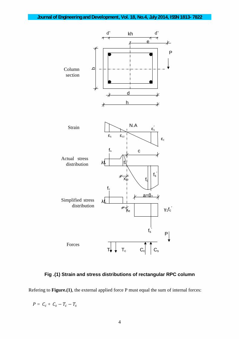
A short rectangular RPC column is shown in Figure.(1) equally reinforced on the two opposite faces and subjected to axial load (P) and bending moment (Pe) around its major axis. The figure also shows the strain distribution, actual stress distribution and an assumed simplified stress distribution. The simplified stress distribution adopted here consists of two rectangular blocks (one compression and the other is tension). The rectangular compression block has much in common with the one specified by ACI 318 code[11] but with coefficients 1 and 1 while the rectangular tension block represents the contribution of steel fibers in resisting tensile stresses with intensity expressed by the coefficient . The values of the coefficients 1, 1 and for different mixes of RPC were evaluated by Hannawayya7 based on extensive experimental tests and will be adopted in the present analysis.
Journal of Engineering and Development, Vol. 18, No.4, July 2014, ISSN 1813- 7822
4
Fig .(1) Strain and stress distributions of rectangular RPC column
Refering to Figure.(1), the external applied force P must equal the sum of internal forces: = + − −
xcr
fr
Tc
xe
λfr
λfr
fc
εcr
Cs Cc Ts
P
a=β1
fs
fs
εc
εs εs
e
b
h
d
kh
P
c
N.A
fs
fs
Column section
Strain
Actual stress distribution
Simplified stress distribution
Forces
γ1fc
d’ d’

Journal of Engineering and Development, Vol. 18, No.4, July 2014, ISSN 1813- 7822
5
∴ = , + , , − ( − − ) − ………………………Eq.1
Considering ′ = = and knowing that the steel ratio of the rectangular column is =
∴ = = …………………………Eq.2
Substituting Eq.2 into Eq.1 gives = + − (ℎ − − ) − Dividing both sides of this equation by ′ ℎ gives = + ( − ) − ( ) ………………………….Eq.3
Equating the area of tension block in the simplified stress distribution to that of the actual stress distribution (Figure.1) gives = (2 − 1)/(2 ) Where is the distance from N.A. to the point in tension zone whose tensile strain is equal to the cracking strain εcr and it can be calculated from strain compatibility as = ∴ = ( ) ………………………….Eq.4
Also the application of strain compatibility gives; = ………………………..….Eq.5
Generally, taking moment of the forces on the column cross section in Fig.1 around the major axis of the section gives; = − + + − + ∴ = , − + , , + (ℎ − − ) − +

Journal of Engineering and Development, Vol. 18, No.4, July 2014, ISSN 1813- 7822
6
Dividing both sides of this equation by ′ ℎ and making use of Eq.2 gives = ( − ) + ( + ) + ( ) ( + ) ……………….Eq.6
As with ordinary reinforced concrete column, the typical interaction diagram of RPC column as shown in Figure.(2) can be divided into many parts depending on the type of failure of the column.
Fig .(2) Interaction diagram for RPC column
1) Balanced failure:
This failure takes place at the onset of tensile steel yielding and concrete crushing, both of which occurring simultaneously. This means that
= = and =
Therefore the value of c is given by Eq.5 becomes; = . …………………………….Eq.7
The strain in the compression steel for this type of failure can be found by using the strain compatibility = ( − ) ....…………………………Eq.8

Journal of Engineering and Development, Vol. 18, No.4, July 2014, ISSN 1813- 7822
7
The value of the concrete ultimate compression strain in RPC is considerably higher than that of ORC indicating that the value of ′ according to Eq.8 will always be greater than and therefore ′ = . Accordingly, it can be stated here that the balanced failure of doubly reinforced RPC sections ensures that = and ′ = . Considering this fact and introducing Eq.4 into Eq.3 gives ( ) = − ( − − ) ………………………Eq.9
= ( − ) +
+ − − ( + ) …………………….Eq.10
The coordinates of the balanced point B on the general interaction diagram of RPC
column shown in (Figure.2) can therefore be obtained from Eqs 9 and 10 which represent respectively the values of the axial load and the associated bending moment causing balanced failure of the column.
2) Tension failure:
When P < (P) , the column fails by yielding of tension reinforcement. Therefore in this case ε > ε (which means that f = f ) and ε = ε . This type of failure happens for c < c or e > e and is represented by portion BC of the interaction diagram of Figure.(2).
Consider a general point E within this portion BC of the diagram. The coordinates of this point can be evaluated as follows;
i. Calculate cb from Eq.7. ii. Assume a value for c such that ′ < < .
(Note that theoretically if = ′ then ′ = 0) iii. Calculate ′ from strain compatibility.
′ = ( − ′ )
and compare to see that; If ′ ≥ , then ′ = If ′ < , then ′ = ′
iv. Find xe from Eq.4. v. Substitute xe and ′ thus found together with = into Eqs 3 and 6 to get the
coordinates of point E.

Journal of Engineering and Development, Vol. 18, No.4, July 2014, ISSN 1813- 7822
8
3) Compression Failure When > , the column fails by crushing of concrete. Therefore in this case <
(which means that < ) and = . This type of failure happens for > or e < e and is represented by portion AB of the interaction diagram of Figure.(2)..
Consider a general point F within this portion AB of the diagram, the coordinates of this point can be evaluated as follows;
I. Calculate cb from Eq.7.
II. Assume a value for c such that < < (Note that theoretically if c=d then = 0)
III. Calculate from strain compatibility = ( − 1)
check to see that < IV. Find = V. Calculate ′ from strain compatibility ′ = (1 − ′ )
Since > the values of ′ will surely be greater than indicating that ′ = in this case of compression failure.
VI. Find xe from Eq.4 VII. Substitute xe and thus found together with ′ = (as discussed in V) into Eqs 3 and
6 to get the coordinates of point F.
4) Pure Bending
When the axial force → 0 and → ∞ then the column will be under pure bending moment. This is a case of < and therefore > (which means that = ) and = . This is represented by point C in the interaction diagram of (Figure.2). The coordinate of this point can be evaluated as follows;
a) Using = and ′ = (1 − ′ )
b) Using xe as given by Eq.4. c) Setting = 0 in Eq3 and substituting , ′ and xe as given in I and II, thus; 0 = + ′ (1 − ′ ) − − ′ (ℎ − − ) ……………Eq.11
d) Searching for the value of c that satisfies Eq.11 and check to see that < where cb is defined by Eq.7.
e) Substitute the value of c found in IV in Eq.6 together with values of , ′ and xe as given
in I and II to get the coordinate ′ as the pure bending moment case.
Journal of Engineering and Development, Vol. 18, No.4, July 2014, ISSN 1813- 7822
9
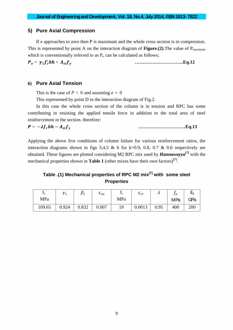
5) Pure Axial Compression
If e approaches to zero then P is maximum and the whole cross section is in compression. This is represented by point A on the interaction diagram of Figure.(2).The value of Pmaximum which is conventionally referred to as Po can be calculated as follows; = + ………………………….Eq.12 6) Pure Axial Tension
This is the case of < 0 and assuming = 0 This represented by point D in the interaction diagram of Fig.2. In this case the whole cross section of the column is in tension and RPC has some
contributing in resisting the applied tensile force in addition to the total area of steel reinforcement in the section. therefore: = − − …………………………Eq.13 Applying the above five conditions of column failure for various reinforcement ratios, the interaction diagrams shown in figs 3,4,5 & 6 for k=0.9, 0.8, 0.7 & 0.6 respectively are obtained. These figures are plotted considering M2 RPC mix used by Hannawayya[7] with the mechanical properties shown in Table 1 (other mixes have their own factors)[7].
Table .(1) Mechanical properties of RPC M2 mix[7] with some steel Properties
fc’
MPa fr
MPa
MPa Es
GPa
109.65 0.924 0.832 0.007 19 0.0013 0.95 400 200

Journal of Engineering and Development, Vol. 18, No.4, July
Fig .(3) Interaction diagram for short rectangular RPC column with k=0.9
Fig .(4) Interaction diagram for short rectangular RPC column with k=0.8
-٠.٦
-٠.١
٠.٤
٠.٩
١.٤
٠ ٠.٠٥ ٠.١
-٠.٦
-٠.١
٠.٤
٠.٩
١.٤
٠ ٠.٠٥ ٠.١
g and Development, Vol. 18, No.4, July 2014, ISSN 1813
10
Interaction diagram for short rectangular RPC column with k=0.9
Interaction diagram for short rectangular RPC column with k=0.8
٠.١٥ ٠.٢ ٠.٢٥ ٠.٣
0.60.70.80.91.0
1.52.0
3.0
٠.١ ٠.١٥ ٠.٢ ٠.٢٥ ٠.٣
0.70.81.01.52.03.0
2014, ISSN 1813- 7822
Interaction diagram for short rectangular RPC column with k=0.9
Interaction diagram for short rectangular RPC column with k=0.8

Journal of Engineering and Development, Vol. 18, No.4, July
Fig .(5) Interaction diagram for short rectangular RPC column with k=0.7
Fig .(6) Interaction diagram for short rectangular RPC column with k=0.6
-٠.٦
-٠.١
٠.٤
٠.٩
١.٤
٠ ٠.٠٥
-٠.٦
-٠.١
٠.٤
٠.٩
١.٤
٠ ٠.٠٥
g and Development, Vol. 18, No.4, July 2014, ISSN 1813
11
Interaction diagram for short rectangular RPC column with k=0.7
Interaction diagram for short rectangular RPC column with k=0.6
٠.١ ٠.١٥ ٠.٢ ٠.٢٥ ٠.٣
0.70.1.01.52.03.0
٠.١ ٠.١٥ ٠.٢ ٠.٢٥
0.60.81.01.52.03.0
2014, ISSN 1813- 7822
Interaction diagram for short rectangular RPC column with k=0.7
Interaction diagram for short rectangular RPC column with k=0.6
790500

Journal of Engineering and Development, Vol. 18, No.4, July 2014, ISSN 1813- 7822
12
Comparison of RPC Column with ordinary concrete column:
The interaction diagrams of a short rectangular RPC column of section dimensions 300X500 mm and having the properties of concrete and steel listed in Table (1) are plotted and compared with the interaction diagrams of a corresponding ordinary concrete rectangular column having same cross section and with the properties of concrete and steel listed in Table( 2).
Table 2 Mechanical properties of ordinary concrete mix with some steel
properties
fc’
MPa fr
MPa
MPa
Es GPa
20.7 0.85 0.85 0.003 - - - 400 200 The following remarks can be concluded from such comparison: 1) Pure axial compression load capacity (Po) of RPC column is about 487.7% and 382.9% of
Po for ORC column with ρ=0.01 and ρ=0.03 respectively. 2) Compression load capacity at balanced condition (Pb) of RPC column is about 671% of
Pb ORC column with ρ=0.01 and ρ=0.03. 3) Bending moment capacity at balanced condition (Mb) of RPC column is about 426.7%
and 279.8% of Mb ORC column with ρ=0.01 and ρ=0.03 respectively. 4) Pure bending moment capacity (Mo) of RPC column is about 559.3% and 262.6% of Mo
ORC column with ρ=0.01 and ρ=0.03 respectively. 5) Pure axial tensile force capacity of RPC column is about 551.2% and 250.4% of that
ORC column with ρ=0.01 and ρ=0.03 respectively.
It is clear that the load carrying capacity of RPC column is much larger than that of ORC column and maximum difference is in the value of the compression load capacity at balanced condition. However, this difference in the axial load capacity between ORC column and RPC column decreases as steel reinforcement ratio increases and this can be related to the fact that the longitudinal steel reinforcement plays a greater role of load carrying capacity in ORC column than in RPC column.
The achievement in concrete tensile strength may be related to the role of steel fibers used in RPC column which increases the concrete ductility and improve its tension, splitting and rupture strength7. In general RPC column is much stronger than ORC column due to the higher compressive strength and tensile strength of the former.

Journal of Engineering and Development, Vol. 18, No.4, July 2014, ISSN 1813- 7822
13
Fig .(7) The interaction diagram of RPC column & ordinary concrete column for ρ=0.01
Fig .(8) The interaction diagram of RPC column & ordinary concrete column for ρ=0.03
-٥٠٠٠
٠
٥٠٠٠
١٠٠٠٠
١٥٠٠٠
٢٠٠٠٠
٠ ٢٠٠ ٤٠٠ ٦٠٠ ٨٠٠ ١٠٠٠ ١٢٠٠ ١٤٠٠
Axia
l for
ce k
N
Moment kN.m
RPC
ORC
-١٠٠٠٠
-٥٠٠٠
٠
٥٠٠٠
١٠٠٠٠
١٥٠٠٠
٢٠٠٠٠
٠ ٢٠٠ ٤٠٠ ٦٠٠ ٨٠٠ ١٠٠٠ ١٢٠٠ ١٤٠٠ ١٦٠٠
Axia
l for
ce k
N
Moment kN.m
RPC
ORC
Journal of Engineering and Development, Vol. 18, No.4, July 2014, ISSN 1813- 7822
14
Conclusions:
1) The necessary equation derived which is used to plot the interaction diagram for RPC tied short column which can be used in the design procedure of such column.
2) The interaction diagrams can be used in the design of RPC tied column having mix properties as mentioned in table 1. (other mixes can have their factors and a new set of interaction diagrams can be found for each mix).
3) Axial compression load capacity, bending moment capacity and axial tension force capacity of RPC column are much higher than those of ORC column due to higher compressive strength and tensile strength of the former. The largest difference is in the compression load capacity at balanced condition.
4) Axial tension force capacity of ORC column is function of longitudinal steel strength only, while in RPC column it is function of concrete strength (due to presence of steel fibers) and longitudinal steel strength.
5) Failure envelopes of RPC columns, being influenced by the compression and tension capacities of concrete and yield stress of longitudinal steel reinforcement, are significantly larger than the corresponding failure envelopes of ORC columns which depend on the compression capacity of concrete only and the yield stress of longitudinal steel reinforcement.
6) As the longitudinal steel reinforcement ratio increases, the difference between the load carrying capacity of RPC column and ORC column decreases.
References:
1. Yunsheng, Z. & Wei, S. “Preparation of C200 green reactive powder concrete and its static-dynamic behaviors”, Cement and Concrete Composite 2008, pp831-838.
2. Richard, P. and Cheyrezy, M., “Reactive Powder Concrete with High Ductility and 200-800 MPa Compressive Strength”, ACI SP144-24, 1994, pp. 507-518.
3. Richard, P. and Cheyrezy, M., “Composition of Reactive Powder Concrete”, Cement and Concrete Research, Vol. 25, No. 7, 1995, pp. 1501-1511.
4. Biolzi, L., Guerrini, G.L. and Rosati, G., “Overall Structural Behavior of High Strength Concrete Specimens”, Construction and Building Materials, Vol. 11, No. 1, 1997, pp. 57-63.
5. Collepardi, S., Coppola, R., Troli, R. and Zaffaroni, P., “Influence of the Superplasticizer Type on the Compressive Strength of Reactive Powder Concrete for Precast Structures”, Congress International BIBM, Venzia, Maggi No 25-28, 1999, pp. 25-30.
Journal of Engineering and Development, Vol. 18, No.4, July 2014, ISSN 1813- 7822
15
6. Cwirzen, A., “The Effect of Heat-Treatment Regime on the Properties of Reactive Powder Concrete”, Advances in Cement Researches, 2007, Vol. 19, No. 1, pp. 25-33.
7. Hannawayya, S.P.Y, “Behavior of Reactive Powder Concrete Beams in Bending “, Ph.D. Thesis, University of Technology, 2010, 239p.
8. Al-Hassani; H.M. and Ibrrahim, S.Kh.,”A Proposed Equation for the Calculation of the Nominal Ultimate Bending Moment Capacity of Rectangular Singly Reinforced RPC Sections”. Engineering and Technology Journal, Vol. 29, No. 5,2011, pp. 925-934.
9. Hussain, L.F., “Punching Shear and Flexural Strength of Fibrous Modified Reactive Powder Concrete Flat Plates”, M.Sc. Thesis, College of Engineering, Al-Mustansiriya University, Baghdad, January 2008, 130p.
10. Yan, P.Y. and Feng, J.W., “Mechanical Behavior of UHPC and UHPC Filled Steel Tubular Stub Columns”, Proceedings of Second International Symposium on Ultra High Performance Concrete, University of Kassel, Kassel, Germany, March 5-7, 2008, pp. 355-364.
11. ACI Committee 318, “Building Code Requirements for Structural Concrete and Commentry”, American Concrete Institute, Farmington Hills, Michigan, 2011.