joseph k. scharrer rockwell international, rocketdyne div
TRANSCRIPT

ROTORDYNAMIC COEFFICIENTS FOR STEPPED
LABYRINTH GAS SEALS
Joseph K . Scharrer Rockwell International, Rocketdyne D i v . Canoga Park, California 91304, U . S . A .
The basic equations are derived for compressible flow in a stepped labyrinth gas seal. The flow is assumed to be completely turbulent in the circumferential direction where the friction factor is determined by the Blasius relation. Linearized zeroth and first-order perturbation equations are developed for small motion about a centered position by an expansion in the eccentricity ratio. The zeroth-order pressure distribution is found by satisfying the leakage equation while the circumferential velocity distribution is determined by satisfying the momentum equations. The first order equations are solved by a separation of variables solution. Integration of the resultant pressure distribution along and around the seal defines the reaction force developed by the seal and the corresponding dynamic coefficients. The results of this analysis are presented in the form of a parametric study, since there are no known experimental data for the rotordynamic coefficients of stepped labyrinth gas seals. The parametric study investigates the relative rotordynamic stability of convergent, straight and divergent stepped labyrinth gas seals. The results show that, generally, the divergent seal is more stable, rotordynamically, than the straight or convergent seals. The results also show that the teeth-on-stator seals are not always more stable, rotordynam- ically, than the teeth-on-rotor seals as was shown by experiment by Childs and Scharrer (198613) for a 15 tooth seal.
INTRODUCTION
The problem of self excited vibration in turbomachinery due to labyrinth seals has led to the development of many analyses for the straight-through type of labyrinth seal, e.g. Childs and Scharrer (1986a), Iwatsubo (1980), Jenny et al. (1984) and Scharrer (1987). There has also been an extensive amount of experimental data collected for the rotordynamic coefficients of straight-through labyrinth seals, e.g. Childs and Scharrer (1986b), Leong (1983), Scharrer (1987) and Wachter and Benckert (1980). The stepped labyrinth seal is as prevalent in turbomachinery as the straight-through labyrinth seal; however, there has been very little or no experimental or analytical work done to quantify the rotordynamic characteristics of this type of seal. This paper presents an analysis of the stepped labyrinth seal which is a derivative of the straight-through analysis of Childs and Scharrer (1986a). The results of this analysis will be presented in the form of a parametric study, since there are no known experimental data.
1 7 7
https://ntrs.nasa.gov/search.jsp?R=19890013530 2019-04-12T12:31:10+00:00Z

PROCEDURE
The analysis presented here is developed for the stepped type of labyrinth seal shown in figure 1. The continuity and momentum equations will be derived for a single cavity control volume as shown in figures 2,3,4 and 5. A leakage model will be employed to account for the axial leakage. The governing equations will be linearized using perturbation analysis for small motion about a centered position. The zeroth-order continuity and momentum equations will be solved to determine the steady state pressure and velocity for each cavity. The first-order continuity and momentum equations will be reduced to linearly independent, algebraic equations by assuming an elliptical orbit for the shaft and a corresponding harmonic response for the pressure and velocity perturbations. The force and force coefficients for the seal are found by integration of the first-order pressure perturbation along and around the shaft.
ASSUMPTIONS
(1) The fluid is an ideal gas. (2) Pressure variations within a chamber are small compared to the pressure differences
(3) The lowest frequency of acoustic resonance in the cavity is much higher than that
(4) The eccentricity of the rotor is small compared to the radial seal clearance. (5) Although the shear stress is significant in the determination of the flow parameters
(velocity, etc.), the shear stress forces on the rotor are small when compared to the pressure forces.
across a seal strip.
of the rotor speed.
(6) The cavity flow is turbulent and isothermal. (7) Added mass terms are neglected. (8 ) The seal strip is midway between steps.
GOVERNING EQUATIONS
Continuity Equation The control volumes of figures 2 and 3 have a unit circumferential width. Their continuity equation is
where the transverse surface area, A, is defined by
Momentum Equations The momentum equation (2) is derived using figures 4 and 5 which show the pressure forces and shear stresses acting on the control volume.
178

The shear stress model is the same as that used by Childs and Scharrer (1986a). The differences are in the dimensionless shear stress lengths and the hydraulic diameter. The dimensionless shear stress length is defined for the teeth-on-rotor labyrinth by
and for teeth-on-stator seals by
The hydraulic diameter, Dhi is defined by
Reduced Equations If equation (1) times the circumferential velocity is now subtracted from equation (2), the following reduced form of the momentum equation is obtained:
The number of variables is reduced by using the ideal gas law to eliminate the density terms.
Leakage Equation The leakage equation (8), flow coefficient, kinetic energy carryover coefficient, and the choked flow solution algorithm are the same as those used by Childs and Scharrer (1986a). The kinetic energy carryover coefficient has the added restriction of being unity when the step height is greater than the clearance.
Perturbation Analysis The solution procedure will be summarized here as the details are given in Childs and Scharrer (1986a). Introduction of the following perturbation variables into the governing equations yields zeroth and first order continuity and momentum equations.
179

Pi = P& + CP1i H; = Cri + CHI v; = V& + €VI< A, = A, + cLiH1
where c = e,/Cr; is the eccentricity ratio.
Zeroth- Order Solution The zeroth-order leakage equation is
R&+lri.ri+l . = w = m , Rsi
and can be solved iteratively to yield zeroth-order cavity pressure values. The zeroth-order circumferential momentum equation is
(9)
ri.r,(Rsi+lV~/Rsi - V&-l) = (Tr,+ari - Ta&aSi)Li (10)
and is solved using a Newton root finding technique to yield zeroth-order cavity circum- ferential velocity components.
First - 0 rde r Solution The governing first-order equations (11,12), define the pressure and velocity fluctuations resulting from the seal clearance function. The continuity and momentum equations follow in order:
where the X's and G's are defined in Appendix A. With an assumption of an ellipt-:a1 shaft orbit, these equations can be reduced to the following system of linear algebraic equations:
where
(Xi-1) = (Pai-l, + Pb-1, + PZ-1, P&, v:-1, Q-1, VZ-1, VZ-JT
(xi+ 1) = (p;+l, p,+, 1 pz+ 1 p ~ + 1 Vai+ 1 vb+ 1 , v ~ + 1 v ~ + (Xi) = (P;,PEi+,P;,P~,v;,v,+,v.,v~)=
+ + The A matrices and column vectors B and C are given in Childs and Scharrer (1986a). To use equation (13) for the entire solution, a system matrix can be formed which is block tridiagonal in the A matrices. The size of this resultant matrix is (8NC X 8NC) since pressure and velocity perturbations at the inlet and the exit are assumed to be zero. This system is easily solved by various linear equation algorithms, and yields a solution of the form:
180

DETERMINATION OF DYNAMIC COEFFICIENT
The force-motion equations for a labyrinth seal are assumed to be of the form
The solution of equation (15) for the stiffness and damping coefficients is the objective of the current analysis. The solution procedure used for this analysis is the same one used by Childs and Scharrer (1986a). The desired solution for the stiffness and damping coefficients is
RESULTS
The geometry used in the parametric study is given in table 1. The pitch of the teeth, the step height, the radial clearance, the tooth height and the inlet radius were all kept constant. The number of teeth were varied between 5 and 15 for the three types of seals investigated: straight, converging and diverging which are shown in figure 6. The operating conditions used for the study are given in table 2. The only variable is the inlet circumferential velocity ratio which was varied between 0.25 and 1.0.
181

I Table 1. Basic Geometry Studied I Radial Clearance,Cr = 0.127 mm (0.005 in)
Tooth Height,B = 3.175 mm (0.125 in) Tooth Pitch,L = 2.175 mm (0.125 in) Seal Radius,Rs = 75.6 mm (2.979 in) Tooth Width,tp = 0.152 mm (0.006 in) Step Height,d = 1.OOO mrn (0.04 in)
Number o f Teeth, NT = 5, 10, 15
I Table 2, Operating Conditions 1 Reservoir Pressure,Pr = 7.0 bar (101.0 psi)
Sump Pressure, P s = 1.01 bar (14.7 psi) Shaft Speed,w = 20,000 cpm (rpm) Temperature,T = 300 K (80degF)
Inlet Swirl Rat io ,qlRsw = 0.25, 0.5, 0.75, 1.0 Fluid is air
Leakage Figures 7 and 8 show leakage versus number of teeth and configuration for teeth-on-rotor and teeth-on-stator seals, respectively. The figures show that the leakage decreases with increasing number of teeth for both teeth-on-rotor and teeth-on-stator seals. The figures also show that the diverging seal yields maximum leakage while the converging seal has the minimum leakage. This result is expected since the effective area of the diverging seal is greater than that of the converging or straight seal.
St $ness Figures 9 and 10 show direct stiffness versus number of teeth and configuration for an inlet circumferential velocity ratio of 1.0 for teeth-on-rotor and teeth-on-stator seals, respec- tively. Figure 9 shows that for converging and straight teeth-on-rotor seals a maximum stiffness occurs for the 10 tooth seal. For the teeth-on-stator seal, figure 10 shows that there is an optimum only for the diverging seal. A maximum may occur for geometries other than those investigated in this study. This phenomenon did not occur for inlet cir- cumferential velocity ratios of 0.25 or 0.5. Both figures also show that the diverging seal yielded the largest value of stiffness. This was true for all of the geometries and operating conditions investigated. Figures 11 and 12 show cross-coupled stiffness versus configuration and number of teeth for an inlet circumferential velocity ratio of 1 .O for teeth-on-rotor and teeth-on-stator seals, respectively. Figure 11 shows that the straight teeth-on-rotor seal yields the maximum cross-coupled stiffness for both the 10 and 15 tooth seals. This phenomenon did not occur for the 0.25 inlet circumferential velocity ratio case. Figure 12 shows that the same is true for the 10 tooth teeth-on-stator seal. This phenomenon did not occur for any inlet circumferential velocity ratio case other than 1.0. The figures also show that the cross- coupled stiffness increases as the number of teeth increase.
182

Damping Figures 13 and 14 show direct damping versus configuration and number of teeth for an inlet circumferential velocity ratio of 1.0 for teeth-on-rotor and teeth-on-stator seals, respectively. Figure 13 shows that the straight teeth-on-rotor seal yields a maximum value of damping for the 10 and 15 tooth seals. This did not occur for an inlet circumferential velocity ratio of 0.25 or 0.5. Figure 14 shows that direct damping is a maximum for the diverging teeth-on-stator seal and a minimum for the converging seal for the 10 and 15 tooth seals. The opposite is true for the 5 tooth seal. The figures also show that direct damping increases as the number of teeth increases.
Relative Rotordynamic Stability The relative stability of the seal configurations investigated will be compared using the whirl frequency ratio which is a ratio of the destabilizing influence divided by the stabilizing influence and is defined as
k wc
When this ratio is greater than 1.0, the seal is a destabilizing influence. The seal with the lowest value is considered to be the most stable. Figures 15 and 16 show the whirl frequency ratio versus seal configuration for inlet circumferential velocity ratios of 0.25 and 1.0, respectively. Both figures show that the teeth-on-rotor seal is more stable than the teeth-on-stator seal for the 5 tooth configuration while the opposite is true for the 15 tooth configuration. The latter result is supported by the test data of Childs and Scharrer (1986b). The 10 tooth configuration seems to be in a transition region. The figures also show that except for the 5 tooth seals at inlet swirls of 1.0, the diverging seal configuration is more stable than the converging and straight configurations. A more complete stability analysis would show that the converging seal may in some cases be a more unstable seal due to the large negative direct stiffness values illustrated in figures 9 and 10.
CONCLUSIONS
This paper has presented an analysis for the rotordynamic coefficients of stepped labyrinth gas seals. The results of this analysis were presented in the form of a parametric study, since no known experimental data existed. The results of this study support the following conclusions:
1) The converging stepped labyrinth seal leaks less than either the straight-through or the divergent seals.
2) The diverging stepped labyrinth seal had a higher value of direct stiffness than either the straight-through or convergent seals for both the teeth-on-rotor and teeth-on-stator case.
3) A maximum direct stiffness was obtained for a 10 tooth convergent teethsn-rotor seal and a 10 tooth divergent teeth-on-stator seal for inlet circumferential velocity ratios of 0.75 or larger.
4) Cross-coupled stiffness increases as the number of teeth, and therefore length (in this study), increase.
183

I 5) Direct damping increases as the number of teeth, and therefore length (in this study), increase.
than either the straight-through or converging seals for both teeth-on-rotor and teeth-on- stat or seals.
7) For the 5 tooth seals, the teeth-on-rotor seal was more stable, rotordynamically, than the teeth-on-stator seals. The opposite was true for the 15 tooth seals.
I 6) For most of the cases studied, the diverging seal is more stable, rotordynamically,
NOMENCLATURE
A B C Direct damping coefficient (Ft/L) Cr Dh H Local radial clearance (L) K Direct stiffness coefficient (F/L) L NT Number of seal strips NC = NT - 1 P Pressure ( F / L 2 ) R Gas constant (L2 /T t2 ) Rs Rsw T Temperature (T) TP V
ar, as
C
e0 k m mr, nr, ms, ns t Time (t) W Shaft angular velocity (l/t) P Density of fluid (MIL3) U Kinematic viscosity ( L 2 / t ) e = eo/Cr Eccentricity ratio 7 Ratio of specific heats
Cross-sectional area of control volume (L2); illustrated in figure (3) Height of labyrinth seal strip (L); illustrated in figure (1)
Nominal radial clearance (L); illustrated in figure (1) Hydraulic diameter of cavity (L); introduced in equation (5 )
Pitch of seal strips (L); illustrated in figure (1)
Number of cavities
Radius of control volume (L); illustrated in figure (1) Surface velocity of rotor (L/t)
Tooth tip width (L); illustrated in figure (1) Average circumferential velocity for control volume (L/t) ; illustrated in figure (2) Dimensionless length upon which shear stress acts; introduced in equation (3) and (4) Cross coupled damping coefficient (Ft/L); in equation (16)
Displacement of the seal rotor from centered position (L) Cross coupled stiffness coefficient (F/L); in equation (16) Leakage mass flow rate per circumferential length (M/Lt)
~
, d Step height (L), illustrated in figure 1
Coefficients for friction factor
184
c -3

Subscripts 0 Zeroth-order component 1 First-order component a i-th chamber value 5 X-direction !J Y-direction r Reservoir value S Sump value
A A : DEFINITION OF FIRST-ORDER COEFFICIENTS
Pa A d XI = - RT
185

186
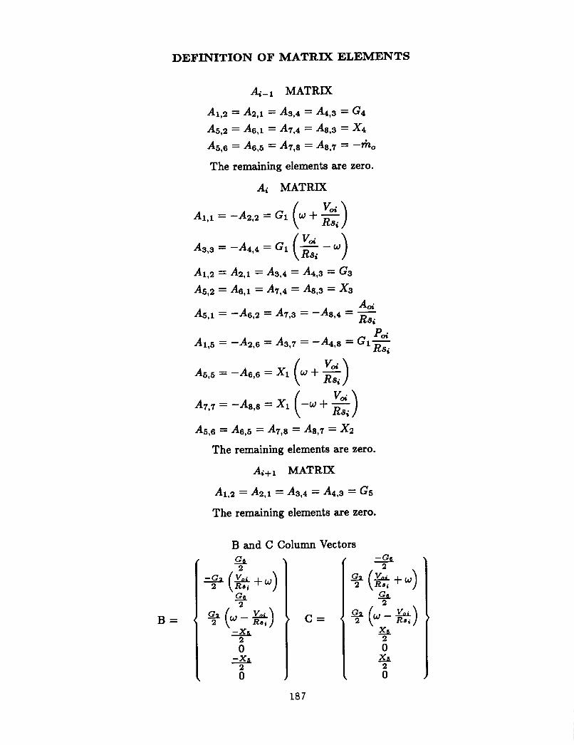
DEFINITION OF MATRIX ELEMENTS
B =
A5,6 = A6,5 = A7,8 = A8,7 = x2
The remaining elements are zero.
A+l MATRJX
A1,2 = A2,i = A3,4 = A4,s = G5
The remaining elements are zero.
B and C Column Vectors
0 -xs
6
C =
187

REFERENCES
1. Childs, D.W., and Scharrer, J.K., 1986a, “An Iwatsubo Based Solution for Laby- rinth Seals: A Comparison to Experimental Results,” ASME Journal of Engineering for Gas Turbines and Power, April, Vol. 108, pp. 325-331
2. Childs, D. W. and Scharrer, J.K., 1986b, “Experimental Rotordynamic Coefficient I
I 86-GT-12.
I I Results for Teeth-On-Rotor and Teeth-On-Stator Labyrinth Gas Seals,” ASME Paper No. I
3. Iwatsubo, T., 1980, “Evaluation of Instability Forces of Labyrinth Seals in Turbines or Compressors,” NASA CP2133 Proceedings of a workshop at Texas A&M University 12- 14 May, entitled Rotordynamic Instability Problems in High Performance Turbomachinery, pp. 139-167.
4. Jenny, R., Wyssmann, H., and Pham, T., 1984, “Prediction of Stiffness and Damp- ing Coefficients for Centrifugal Compressor Labyrinth Seals,” ASME Paper No. 84-GT-86. Presented at the 29th International Gas Turbine Conference and Exhibit, Amsterdam, The Netherlands, June 4-7.
5. Leong, Y.M.S., 1983, “Lateral Forces Induced by Flow Through Model Labyrinth Glands,” PhD Diss., Heriot-Watt University, Edinburgh, June.
6. Scharrer, J.K., 1987, “A Comparison of Experimental and Theoretical Results for Labyrinth Gas Seals,” PhD Dissertation, Texas A&M University, May.
7. Wachter, J. and Benckert, H., 1980, “Flow Induced Spring Coefficients of Labyrinth Seals for Applications in Rotordynamics,” NASA CP 2133, Proceedings of a workshop held at Texas A&M University, 12-14 May, Entitled Rotordynamic Instability Problems of High Performance Turbomachinery, pp. 189-212.
‘Y
b l - 4 I
Figure 1. A Typical Stepped Labyrinth Seal.
188

8
aV, d e - vi+ - a9 f i l l + ,
'"I
Figure 3. Isometric View of control Volume.
C
7; ar L,Rs
Figure 4. Forces on Control Volume.
189

Figure 5. Pressure Forces on Control Volume.
FLOW
Figure 6. Configurations Studied.
190

STEPPED LABYRINTH SEAL T E n H -0 t4 - ROTOR
0 . 0 5 4
0 . 0 5 2
0.05
0 . 0 4 6
0 . 0 4 8
5 0 . 0 4 4
w 0 . 0 4 2 $ 0.04
0.038
0.030
0 . 0 3 4
b . 0 3 2
c.
-I v
I 1
1 0 0.03 -I
5 NUtAREn Or TEETH . O,VLnC,NC o CONVERCIt4C 4 S l R A J C t U
5
Figure 7. Leakage versus number of teeth and seal configuration for a teeth-on-rotor seal.
STEPPED LABYRINTH SEAL 1 E n H-ON- fl AT OR
J 0.054
0.032
0.03 -I I 10 15 5
NUMDtR Or TtfTH . O,YtRC,NC o CONVERCINC + SIRAICHl
Figure 8. Leakage versus number of teeth and seal configuration for a teeth-on-stator seal.
191

h
E : Y
t W
a: 0
600
5 00
400
300
200
100
0
-100
STEPPED LABYRINTH SEAL fEf3H-ON-ROTOR VIRSI 1.0 ,
I 5 1 1 I
10 15
0 CONVERCINC NUMFER OF TEElH DMRC,NC + STAAICHT
Figure 9. Direct Stiffness versus number of teeth and seal configuration for a teeth-on-rotor seal. Inlet circumferential velocity ratio is 1.0.
STEPPED LABYRINTH SEAL 2 0 0
180
180
1 4 0
E 120 ‘r 100 Y
E- 80
60 x::
c 0
c 8 - 2 0
- 4 0
- 6 0
- 80
-100
0
I I I
5 10 15
Nuhiem CF TCETH CONVERCINC + STRAICMT o DNERCINC
Figure 10. Direct Stiffness versus number of teeth and seal configuration for a teeth-on-stator seal. Inlet circumferential velocity ratio is 1.0.
192

STEPPED LABYRIFJTH SEAL TEETH-ON-ROTOR V/RSw 1.0
1.5
a50
800 - E 7 5 0 -
700 -
h
2 v
E p Llso-'
k i 6 0 0 -
'i' 3 0 0 - 8
0
$5 5 5 0 -
8 4 5 0 -
4 0 0 - 3 5 0 -r I 1 1 8
0.0 l 5
0.3 ! . _
CONVERGE STRAICHT ONERCE
COt4FCUMnON 0 S f E n H + 10 T E t t H 13 TEETH
Figure 11. Cross-coupled stiffness versus seal configuration and number of teeth for a teeth-on-rotor seal. Inlet circumferential velocity ratio is 1.0.
a S T E n H CONFIGURATION . l, T E ~ T H + 10 TEEtH
Figure 12. Cross-coupled stiffness versus seal configuration and number of teeth for a teeth-on-stator seal. Inlet circumferential velocity ratio is 1.0.
193

BOO -
- S O 0 -
<
4 0 0 -
300 - 200 -
100 - b - f j
0 I
STRAICHT ONERCL CONVERGE
Figure 13. Direct damping versus seal configuration and number of teeth for a teeth-on-rotor seal. Inlet circumferential velocity ratio is 1.0.
X X u CY 2 5 0 -
> E a 200 - t; W
0 1 5 0 -
100 - 5 0 f
CONVER C E STRAIGHT ONERCE
COI~FICURATION 0 5 TEETH 4 10 TEElH 15 TEETH
Figure 14. Direct damping versus seal configuration and number of teeth for a teeth-on-rotor seal. Inlet circumferential velocity ratio is 1.0.
194

STEPPED LABYRIIdTH SEAL 2.4
2.2
2
1.6
1.6
1.4
1.2
1
0.6
0.6
0.4
0.2
0
-0.2 1 1
1 -0.4 0.5 0.75 0.23
SO INLET VEL. s3 + RS RO b o RC
Figure 16. Whirl frequency ratio versus seal configuration for an inlet circumferential velocity ratio of 0.26.
STEPPED LABYRINTH SEAL
Figure 10. Whirl frequency ratio versus seal configuration for an inlet circumferential velocity ratio of 1.0.
195