joint oil analysis program manual volume ii
TRANSCRIPT

(NAVY) NAVAIR 17-15-50.2 (ARMY) TM 38-301-2 (AIR FORCE) T.O. 33-1-37-2 (COAST GUARD) CGTO 33-1-37-2
30 August 2013
TECHNICAL MANUAL
JOINT OIL ANALYSIS PROGRAM MANUAL
VOLUME II
SPECTROMETRIC AND PHYSICAL TEST LABORATORY OPERATING REQUIREMENTS
AND PROCEDURES
This manual supersedes NAVAIR 17-15-50.2 dated 31 July 2012.
This manual is incomplete without NAVAIR-17-15-50.1, NAVAIR-17-15-50.3 and
NAVAIR-17-15-50.4
DISTRIBUTION STATEMENT A. Approved for public release; distribution is unlimited, determined on 30 August 2013. Other requests for this document shall be referred to Navy Oil Analysis Program, Naval Air Warfare Center, Aircraft Division, AIR-4.4.6, 22229 Elmer Road, Patuxent River MD 20670-1534 for all volumes.
DESTRUCTION NOTICE - For unclassified, limited documents, destroy by any method that will prevent disclosure of contents or reconstruction of the document.
Published by direction of Commander, Naval Air Systems Command
under the authority of the Joint Oil Analysis Program Regulation AFI 21-131 (I), AR 700-132 and OPNAVINST 4731.1C.
0817LP9840919
(NAVY) NAVAIR 17-15-50.2 (ARMY) TM 38-301-2 (AIR FORCE) T.O. 33-1-37-2 (COAST GUARD) TO 33-1-37-2
Page A
30 August 2013
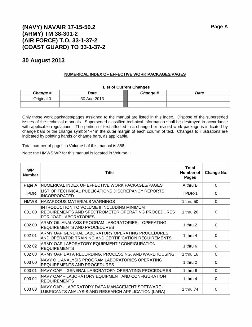
NUMERICAL INDEX OF EFFECTIVE WORK PACKAGES/PAGES
List of Current Changes
Change # Date Change # Date Original 0 30 Aug 2013
Only those work packages/pages assigned to the manual are listed in this index. Dispose of the superseded issues of the technical manuals. Superseded classified technical information shall be destroyed in accordance with applicable regulations. The portion of text affected in a changed or revised work package is indicated by change bars or the change symbol “R” in the outer margin of each column of text. Changes to illustrations are indicated by pointing hands or change bars, as applicable.
Total number of pages in Volume I of this manual is 386.
Note: the HMWS WP for this manual is located in Volume II
WP Number Title
Total Number of
Pages Change No.
Page A NUMERICAL INDEX OF EFFECTIVE WORK PACKAGES/PAGES A thru B 0
TPDR LIST OF TECHNICAL PUBLICATIONS DISCREPANCY REPORTS INCORPORATED TPDR-1 0
HMWS HAZARDOUS MATERIALS WARNINGS 1 thru 50 0
001 00 INTRODUCTION TO VOLUME II INCLUDING MINIMUM REQUIREMENTS AND SPECTROMETER OPERATING PROCEDURES FOR JOAP LABORATORIES
1 thru 26 0
002 00 ARMY OIL ANALYSIS PROGRAM LABORATORIES – OPERATING REQUIREMENTS AND PROCEDURES 1 thru 2 0
002 01 ARMY OAP GENERAL LABORATORY OPERATING PROCEDURES AND OPERATOR TRAINING AND CERTIFICATION REQUIREMENTS 1 thru 4 0
002 02 ARMY OAP LABORATORY EQUIPMENT / CONFIGURATION REQUIREMENTS 1 thru 6 0
002 03 ARMY OAP DATA RECORDING, PROCESSING, AND WAREHOUSING 1 thru 16 0
003 00 NAVY OIL ANALYSIS PROGRAM LABORATORIES OPERATING REQUIREMENTS AND PROCEDURES 1 thru 2 0
003 01 NAVY OAP – GENERAL LABORATORY OPERATING PROCEDURES 1 thru 8 0
003 02 NAVY OAP – LABORATORY EQUIPMENT AND CONFIGURATION REQUIREMENTS 1 thru 4 0
003 03 NAVY OAP - LABORATORY DATA MANAGEMENT SOFTWARE - LUBRICANTS ANALYSIS AND RESEARCH APPLICATION (LARA) 1 thru 74 0
(NAVY) NAVAIR 17-15-50.2 (ARMY) TM 38-301-2 (AIR FORCE) T.O. 33-1-37-2 (COAST GUARD) TO 33-1-37-2
Page B
30 August 2013
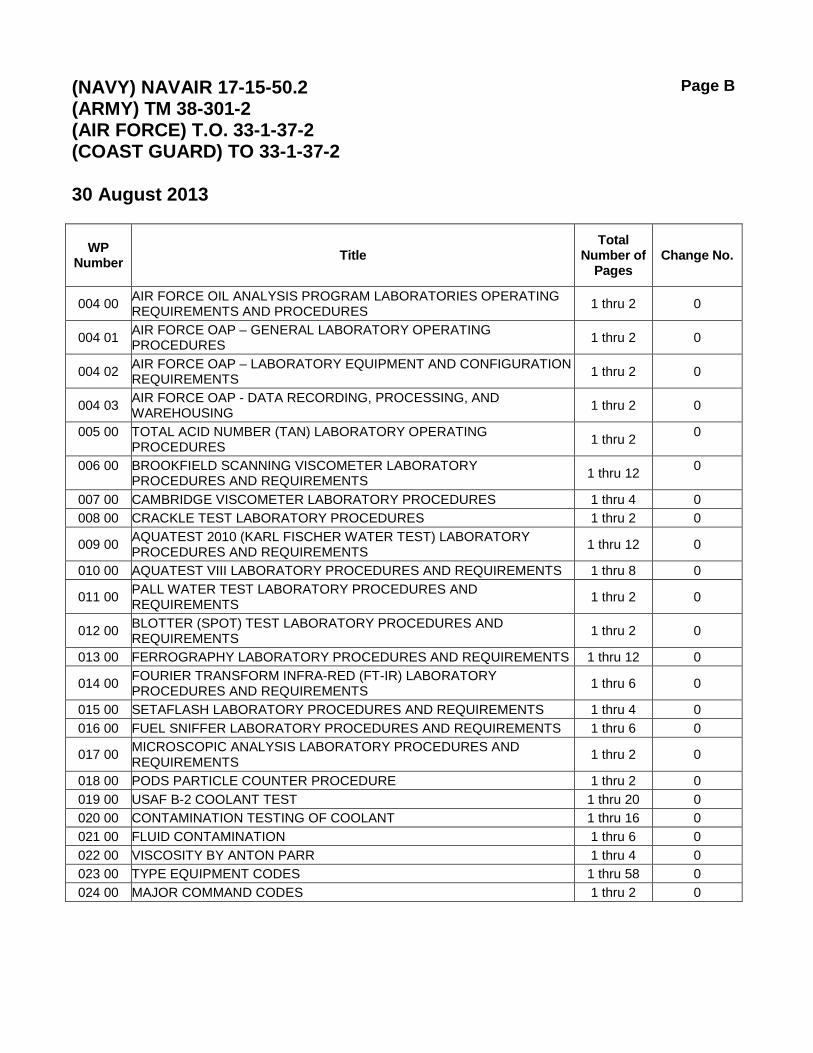
WP Number Title
Total Number of
Pages Change No.
004 00 AIR FORCE OIL ANALYSIS PROGRAM LABORATORIES OPERATING REQUIREMENTS AND PROCEDURES 1 thru 2 0
004 01 AIR FORCE OAP – GENERAL LABORATORY OPERATING PROCEDURES 1 thru 2 0
004 02 AIR FORCE OAP – LABORATORY EQUIPMENT AND CONFIGURATION REQUIREMENTS 1 thru 2 0
004 03 AIR FORCE OAP - DATA RECORDING, PROCESSING, AND WAREHOUSING 1 thru 2 0
005 00 TOTAL ACID NUMBER (TAN) LABORATORY OPERATING PROCEDURES 1 thru 2 0
006 00 BROOKFIELD SCANNING VISCOMETER LABORATORY PROCEDURES AND REQUIREMENTS 1 thru 12 0
007 00 CAMBRIDGE VISCOMETER LABORATORY PROCEDURES 1 thru 4 0 008 00 CRACKLE TEST LABORATORY PROCEDURES 1 thru 2 0
009 00 AQUATEST 2010 (KARL FISCHER WATER TEST) LABORATORY PROCEDURES AND REQUIREMENTS 1 thru 12 0
010 00 AQUATEST VIII LABORATORY PROCEDURES AND REQUIREMENTS 1 thru 8 0
011 00 PALL WATER TEST LABORATORY PROCEDURES AND REQUIREMENTS 1 thru 2 0
012 00 BLOTTER (SPOT) TEST LABORATORY PROCEDURES AND REQUIREMENTS 1 thru 2 0
013 00 FERROGRAPHY LABORATORY PROCEDURES AND REQUIREMENTS 1 thru 12 0
014 00 FOURIER TRANSFORM INFRA-RED (FT-IR) LABORATORY PROCEDURES AND REQUIREMENTS 1 thru 6 0
015 00 SETAFLASH LABORATORY PROCEDURES AND REQUIREMENTS 1 thru 4 0 016 00 FUEL SNIFFER LABORATORY PROCEDURES AND REQUIREMENTS 1 thru 6 0
017 00 MICROSCOPIC ANALYSIS LABORATORY PROCEDURES AND REQUIREMENTS 1 thru 2 0
018 00 PODS PARTICLE COUNTER PROCEDURE 1 thru 2 0 019 00 USAF B-2 COOLANT TEST 1 thru 20 0 020 00 CONTAMINATION TESTING OF COOLANT 1 thru 16 0 021 00 FLUID CONTAMINATION 1 thru 6 0 022 00 VISCOSITY BY ANTON PARR 1 thru 4 0 023 00 TYPE EQUIPMENT CODES 1 thru 58 0 024 00 MAJOR COMMAND CODES 1 thru 2 0


(NAVY) NAVAIR 17-15-50.2 (ARMY) TM 38-301-2 (AIR FORCE) T.O. 33-1-37-2 (COAST GUARD) TO 33-1-37-2
TPDR-1
30 August 2013
NAVAL AIR SYSTEMS COMMAND TECHNICAL MANUAL PROGRAM
LIST OF TECHNICAL PUBLICATIONS DEFICIENCY REPORTS INCORPORATED
1. The TPDRs listed below have been incorporated in this issue.
Activity Report Control Number Location
none

NAVAIR 17-15-50.2 TM 38-301-2 T.O. 33-1-37-2 CGTO 33-1-37-2
WP HMWS Page 1 of 50
Change 0 30 August 2013
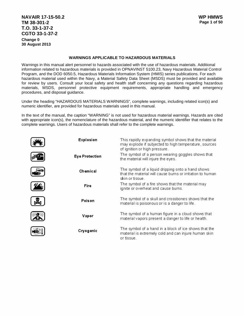
WARNINGS APPLICABLE TO HAZARDOUS MATERIALS
Warnings in this manual alert personnel to hazards associated with the use of hazardous materials. Additional information related to hazardous materials is provided in OPNAVINST 5100.23, Navy Hazardous Material Control Program, and the DOD 6050.5, Hazardous Materials Information System (HMIS) series publications. For each hazardous material used within the Navy, a Material Safety Data Sheet (MSDS) must be provided and available for review by users. Consult your local safety and health staff concerning any questions regarding hazardous materials, MSDS, personnel protective equipment requirements, appropriate handling and emergency procedures, and disposal guidance. Under the heading “HAZARDOUS MATERIALS WARNINGS”, complete warnings, including related icon(s) and numeric identifier, are provided for hazardous materials used in this manual. In the text of the manual, the caption “WARNING” is not used for hazardous material warnings. Hazards are cited with appropriate icon(s), the nomenclature of the hazardous material, and the numeric identifier that relates to the complete warnings. Users of hazardous materials shall refer to the complete warnings.

NAVAIR 17-15-50.2 TM 38-301-2 T.O. 33-1-37-2 CGTO 33-1-37-2
WP HMWS Page 2 of 50
Change 0 30 August 2013
NAME HMWS Index Nbr.
HMWS Page Nbr.
Tricresyl Phosphate 1 4 MIL-PRF-680C (Degreasing Solvent) 2 5 SAE-J1899 (lube Oil) 3 6 SAE-J1966 (Lube Oil) 4 7 MIL-PRF-2104H (Lube Oil) 5 8 MIL-PRF-2105E (Lube Oil) 6 8 SAE-J2360 (Lube Oil) 7 9 MIL-PRF-5606H 8 9 MIL-PRF-6081D (Lube Oil) 9 10 MIL-6082E 10 10 MIL-PRF-6083G 11 11 MIL-PRF-7808L 12 11 MIL-PRF-8188D 13 12 MIL-PRF-83282 14 12 MIL-PRF-9000J 15 13 MIL-PRF-9000K 16 14 MS-9250 17 14 MIL-L-15019E 18 15 MIL-DTL-17111E 19 15 MIL-PRF-17331(SH) 20 16 MIL-PRF-17672E 21 16 MIL-H-19457D 22 17 MIL-PRF-21260E 23 17 HIL-H-22072C 24 18 MIL-L-22851D 25 18 MIL-PRF-23699F 26 19 MIL-L-27502 27 19 MIL-PRF-46170D (Hyd. Fluid) 28 20 DOD-PRF-85734A 29 20 MIL-PRF-87257B 30 21 Skydrol Hydraulic Fluid 31 21 Philips 66 Reference Oil 50 32 22 Alcohol, Isopropyl 33 23 BioXcel 34 23 1-Bromonaphthalene 96% 35 24 2(3H)-Benzothiazolethione, Sodium Salt (Liquid), 36 25

NAVAIR 17-15-50.2 TM 38-301-2 T.O. 33-1-37-2 CGTO 33-1-37-2
WP HMWS Page 3 of 50
Change 0 30 August 2013
NAME HMWS Index Nbr.
HMWS Page Nbr.
Acetic Acid, 96%, 37 26 Benzotriazole-1,2,3 38 27 BIO-TEK 134 HI-SOLV (Solvent) 39 28 Chevron FLO-COOL 180 40 28 COOLANOL 25R 41 29 Diesel Fuel NO. 2 42 30 Electron (ECOLINK ) 43 31 Ethylene Glycol 44 32 Gasoline 45 33 Heptane 46 34 Hexane 47 35 JP-5 Jet Fuel 48 36 JP-8 Jet Fuel 49 37 Methanol (Methyl alcohol) 50 38 Nitric Acid (65% - 70%) 51 38 Petroleum Ether 52 39 pH 4 Buffer 53 40 pH 7.00 Buffer 54 40 Phosphoric Acid 85% 55 40 PhotoVolt Aquatest 2% Water Standard 56 41 PhotoVolt Aquatest Generator Solution 57 42 PhotoVolt Aquatest Vessel Solution 58 43 p-Naphtholbenzein 59 44 Potassium Hydroxide 0.1N Solution in Methanol 60 45 S60S Viscometer Calibration Standard 61 46 Silicone (Liquid) 62 46 Sodium Hydroxide 0.1N 63 47 Toluene 64 48 Viscometer Calibration Standard Petroleum - Cannon 65 49 Viscometer Calibration Standard Synthetic - Cannon 66 49
NAVAIR 17-15-50.2 TM 38-301-2 T.O. 33-1-37-2 CGTO 33-1-37-2
WP HMWS Page 4 of 50
Change 0 30 August 2013
HAZARDOUS MATERIALS WARNINGS
INDEX MATERIAL WARNING
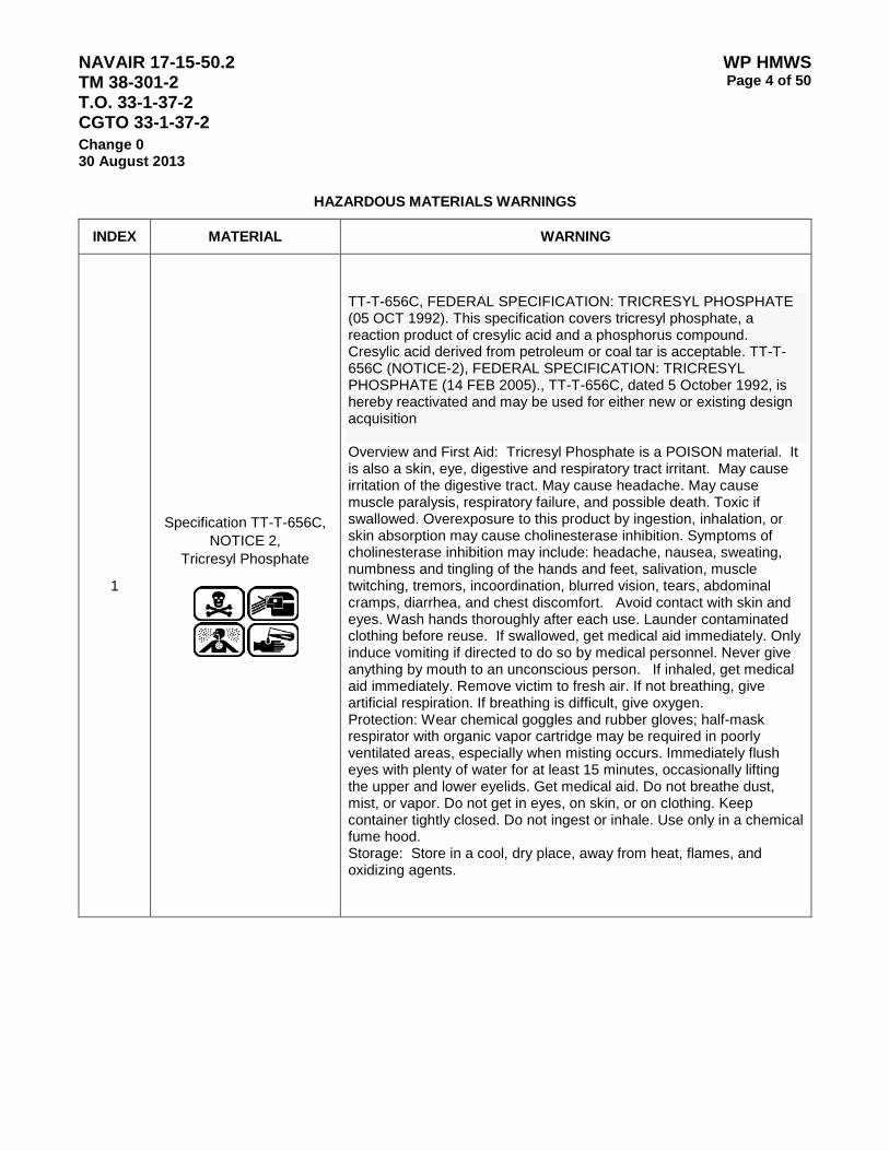
1
Specification TT-T-656C,
NOTICE 2, Tricresyl Phosphate
TT-T-656C, FEDERAL SPECIFICATION: TRICRESYL PHOSPHATE (05 OCT 1992). This specification covers tricresyl phosphate, a reaction product of cresylic acid and a phosphorus compound. Cresylic acid derived from petroleum or coal tar is acceptable. TT-T-656C (NOTICE-2), FEDERAL SPECIFICATION: TRICRESYL PHOSPHATE (14 FEB 2005)., TT-T-656C, dated 5 October 1992, is hereby reactivated and may be used for either new or existing design acquisition Overview and First Aid: Tricresyl Phosphate is a POISON material. It is also a skin, eye, digestive and respiratory tract irritant. May cause irritation of the digestive tract. May cause headache. May cause muscle paralysis, respiratory failure, and possible death. Toxic if swallowed. Overexposure to this product by ingestion, inhalation, or skin absorption may cause cholinesterase inhibition. Symptoms of cholinesterase inhibition may include: headache, nausea, sweating, numbness and tingling of the hands and feet, salivation, muscle twitching, tremors, incoordination, blurred vision, tears, abdominal cramps, diarrhea, and chest discomfort. Avoid contact with skin and eyes. Wash hands thoroughly after each use. Launder contaminated clothing before reuse. If swallowed, get medical aid immediately. Only induce vomiting if directed to do so by medical personnel. Never give anything by mouth to an unconscious person. If inhaled, get medical aid immediately. Remove victim to fresh air. If not breathing, give artificial respiration. If breathing is difficult, give oxygen. Protection: Wear chemical goggles and rubber gloves; half-mask respirator with organic vapor cartridge may be required in poorly ventilated areas, especially when misting occurs. Immediately flush eyes with plenty of water for at least 15 minutes, occasionally lifting the upper and lower eyelids. Get medical aid. Do not breathe dust, mist, or vapor. Do not get in eyes, on skin, or on clothing. Keep container tightly closed. Do not ingest or inhale. Use only in a chemical fume hood. Storage: Store in a cool, dry place, away from heat, flames, and oxidizing agents.

NAVAIR 17-15-50.2 TM 38-301-2 T.O. 33-1-37-2 CGTO 33-1-37-2
WP HMWS Page 5 of 50
Change 0 30 August 2013
HAZARDOUS MATERIALS WARNINGS (CONTINUED)
INDEX MATERIAL WARNING
2
MIL-PRF-680C, Degreasing Solvent
MIL-PRF-680C, PERFORMANCE SPECIFICATION: DEGREASING SOLVENT (25 MAR 2010). This specification covers degreasing solvent that consists of four types of petroleum distillates. The different types are referred to as "Stoddard solvent", "141 degrees Fahrenheit (degrees F) (60.6 degrees Celsius (degrees C)) solvent", "200 degrees F (93.3 degrees C) solvent", and "141 degrees F d-limonene blended solvent". They are used for degreasing of machine parts in equipment maintenance. MIL-PRF-680C, degreasing solvent is not classified as dangerous. Good general ventilation should be sufficient to control worker exposure to airborne contaminants. If this product contains ingredients with exposure limits, use process enclosures, local exhaust ventilation or other engineering controls to keep worker exposure below any recommended or statutory limits. Hygiene Measures: Wash hands, forearms and face thoroughly after handling compounds and before eating, smoking and using the lavatory and at the end of the day. During formulation, follow good industrial hygiene practice. Eye and Hand Protection: Safety glasses with side shields. Natural rubber (latex) gloves. . In case of contact with eyes, rinse immediately with plenty of water. Check for and remove any contact lenses Obtain medical attention if symptoms occur. If ingested do not induce vomiting. Never give anything by mouth to an unconscious person. Get medical attention if symptoms appear. If inhaled, remove to fresh air. If not breathing, give artificial respiration. Get medical attention if symptoms appear. Wash with soap and water. Obtain medical attention if symptoms occur.
NAVAIR 17-15-50.2 TM 38-301-2 T.O. 33-1-37-2 CGTO 33-1-37-2
WP HMWS Page 6 of 50
Change 0 30 August 2013
HAZARDOUS MATERIALS WARNINGS (CONTINUED)
INDEX MATERIAL WARNING
3
SAE-J1899, Lubricating Oil
OIL, LUBRICATING, AIRCRAFT PISTON ENGINE (ASHLESS DISPERSANT) SAE-J1899, ADOPTION NOTICE; OIL, LUBRICATING AIRCRAFT PISTON ENGINE (ASHLESS DISPERSANT)This SAE Standard establishes the requirements for lubricating oils containing ashless dispersant additives to be used in four-stroke cycle, reciprocating piston aircraft engines. This document covers the same lubricating oil requirements as the former military specification MIL-L-22851. Users should consult their airframe or engine manufacturer’s manuals for the latest listing of acceptable lubricants. SAE-J1899 Grades: W65 W80 W100 W120 Lubricating oil, SAE-J1899, is a skin, eye, and respiratory tract irritant. Use in a well ventilated area, especially when exposure to hot oil or mist is possible. Avoid contact with skin and eyes. Wash hands thoroughly after each use. Launder contaminated clothing before reuse. If ingested do not induce vomiting. Never give anything by mouth to an unconscious person. Get medical attention if symptoms appear. Store in a cool, dry place, away from heat, flames, and oxidizing agents. Protection: Wear chemical goggles and rubber gloves; half-mask respirator with organic vapor cartridge may be required in poorly ventilated areas, especially when misting occurs. If eye contact occurs, flush immediately with large amounts of water for 15 minutes and seek medical attention. If skin contact occurs, wash with soap and water, remove contaminated clothing and shoes. If inhalation occurs, remove from area to fresh air.

NAVAIR 17-15-50.2 TM 38-301-2 T.O. 33-1-37-2 CGTO 33-1-37-2
WP HMWS Page 7 of 50
Change 0 30 August 2013
HAZARDOUS MATERIALS WARNINGS (CONTINUED)
INDEX MATERIAL WARNING
4
SAE-J1966, Lubricating Oil,
Aircraft Piston Engine, Mineral Oil,
Refer to MIL-PRF-6082
SAE-J1966, ADOPTION NOTICE; OILS, LUBRICATING, AIRCRAFT PISTON ENGINE (NONDISPERSANT MINERAL OIL) (01 NOV 1995) [SUPERSEDING MIL-L-6082]. SAE-J1966, "Lubricating Oils, Aircraft Piston Engine (Nondispersant Mineral Oil)", was adopted on 01-NOV-95 for use by the Department of Defense (DoD). This SAE Standard establishes the requirements for nondispersant, mineral lubricating oils to be used in four-stroke cycle piston aircraft engines. This document covers the same lubricating oil requirements as the former military specification MIL-L-6082. Users should consult their airframe or engine manufacturer’s manuals for the latest listing of acceptable lubricants. Aircraft lubricating oil, SAE-J1966, is toxic, and a skin, eye, and respiratory tract irritant. If lubricating oil is decomposed by heat, toxic gases are released. Keep away from open flame, sparks, or heat. Use in a well ventilated area, especially when exposure to hot oil or mist is possible. Wash hands thoroughly after use. Launder contaminated clothing before re-use; discard contaminated boots or shoes if oil soaked. Keep containers closed when not in use. Avoid strong oxidizing agents. Protection: Wear chemical goggles, rubber gloves, and protective clothing; full-face piece continuous supplied air respirator required in poorly ventilated areas, especially when misting occurs. If eye contact occurs, flush immediately with large amounts of water for 15 minutes and seek medical attention. If skin contact occurs, wash with soap and water; remove contaminated clothing and shoes. If ingested, do not induce vomiting, seek medical attention. If inhalation occurs, remove from area to fresh air.
NAVAIR 17-15-50.2 TM 38-301-2 T.O. 33-1-37-2 CGTO 33-1-37-2
WP HMWS Page 8 of 50
Change 0 30 August 2013
HAZARDOUS MATERIALS WARNINGS (CONTINUED)
INDEX MATERIAL WARNING
5
MIL-PRF-2104H Lubricating Oil,
Internal Combustion Engine,
MIL-PRF-2104H, PERFORMANCE SPECIFICATION: LUBRICATING OIL, INTERNAL COMBUSTION ENGINE, COMBAT/TACTICAL SERVICE (12 JUL 2004) [SUPERSEDING MIL-L-2104F]. This performance specification covers engine oils suitable for lubrication of reciprocating compression-ignition internal combustion engines and for power transmission fluid applications in combat/tactical service equipment. Aircraft lubricating oil, MIL-PRF-2104H, is toxic, and a skin, eye, and respiratory tract irritant. If lubricating oil is decomposed by heat, toxic gases are released. Keep away from open flame, sparks, or heat. Use in a well ventilated area, especially when exposure to hot oil or mist is possible. Wash hands thoroughly after use. Launder contaminated clothing before re-use; discard contaminated boots or shoes if oil soaked. Keep containers closed when not in use. Avoid strong oxidizing agents. Protection: Wear chemical goggles, rubber gloves, and protective clothing; full-face piece continuous supplied air respirator required in poorly ventilated areas, especially when misting occurs. If eye contact occurs, flush immediately with large amounts of water for 15 minutes and seek medical attention. If skin contact occurs, wash with soap and water; remove contaminated clothing and shoes. If ingested, do not induce vomiting, seek medical attention. If inhalation occurs, remove from area to fresh air.
6
MIL-PRF-2105E, NOTICE 3,
Lubricating Oil, Gear Multipurpose
Refer to SAE-J2360
MIL-PRF-2105E (NOTICE 3), PERFORMANCE SPECIFICATION: LUBRICATING OIL, GEAR, MULTIPURPOSE (26 AUG 2008) [SUPERSEDING MIL-L-2105D] [S/S BY SAE-J2360]., MIL-PRF-2105E, dated 22 August 1995, is hereby canceled as of 16 February 2005 and has been replaced by Society of Automotive Engineers (SAE) J2360, "Lubricating Oil, Gear Multipurpose (Metric) Use." Aircraft lubricating oil, SAE-J2360, is toxic, and a skin, eye, and respiratory tract irritant. If lubricating oil is decomposed by heat, toxic gases are released. Keep away from open flame, sparks, or heat. Use in a well ventilated area, especially when exposure to hot oil or mist is possible. Wash hands thoroughly after use. Launder contaminated clothing before re-use; discard contaminated boots or shoes if oil soaked. Keep containers closed when not in use. Avoid strong oxidizing agents. Protection: Wear chemical goggles, rubber gloves, and protective clothing; full-face piece continuous supplied air respirator required in poorly ventilated areas, especially when misting occurs. If eye contact occurs, flush immediately with large amounts of water for 15 minutes and seek medical attention. If skin contact occurs, wash with soap and water; remove contaminated clothing and shoes. If ingested, do not induce vomiting, seek medical attention. If inhalation occurs, remove from area to fresh air.

NAVAIR 17-15-50.2 TM 38-301-2 T.O. 33-1-37-2 CGTO 33-1-37-2
WP HMWS Page 9 of 50
Change 0 30 August 2013
HAZARDOUS MATERIALS WARNINGS (CONTINUED)
INDEX MATERIAL WARNING
7
SAE-J2360
Lubricating Oil
This SAE Standard covers multipurpose gear lubricating military oils. This standard is equivalent to MIL-PRF-2105 when all requirements are met. API Category GL-5 designates the type of service characteristic of gears, particularly hypoids in automotive axles under high-speed and/or low-speed, high-torque conditions. Lubricants qualified under U.S. Military specification MIL-L-2105D (formerly MIL-L-2015C), MIL-PRF-2105E and SAE J2360 satisfy the requirements of the API GL-5 service designation. SAE-J2360 grades: 75W 80W-90 85W-140 Aircraft lubricating oil, SAE-J2360, is toxic, and a skin, eye, and respiratory tract irritant. If lubricating oil is decomposed by heat, toxic gases are released. Keep away from open flame, sparks, or heat. Use in a well ventilated area, especially when exposure to hot oil or mist is possible. Wash hands thoroughly after use. Launder contaminated clothing before re-use; discard contaminated boots or shoes if oil soaked. Keep containers closed when not in use. Avoid strong oxidizing agents. Protection: Wear chemical goggles, rubber gloves, and protective clothing; full-face piece continuous supplied air respirator required in poorly ventilated areas, especially when misting occurs. If eye contact occurs, flush immediately with large amounts of water for 15 minutes and seek medical attention. If skin contact occurs, wash with soap and water; remove contaminated clothing and shoes. If ingested, do not induce vomiting, seek medical attention. If inhalation occurs, remove from area to fresh air.
8
MIL-PRF-5606H AMENDMENT 3, Hydraulic Fluid,
Aircraft, Missile and Ordinance,
Petroleum Base,
MIL-PRF-5606H (AMENDMENT 3), PERFORMANCE SPECIFICATION: HYDRAULIC FLUID, PETROLEUM BASE; AIRCRAFT, MISSILE, AND ORDNANCE (07 SEP 2006) [S/S BY MIL-PRF-87257 OR MIL-PRF-83282]., This specification describes the characteristics and provides the requirements for a petroleum base hydraulic fluid for use in the -54 Deg. C to +135 Deg. C temperature range. This fluid is identified by military symbol OHA and NATO Code No. H-515. Hydraulic fluid, MIL-PRF-5606H, is flammable, toxic and an irritant. Keep away from heat, sparks, open flames and static electricity. Use in well-ventilated area, especially when exposure to hot oil or oil mist is possible. Eye contact: Flush with water for 15 minutes; get medical attention. Skin contact: Wash with soap and water. Ingestion: Do not induce vomiting; get medical attention. Wash hands with soap and water after use and before eating, drinking or smoking. If Swallowed: drink plenty of water, DO NOT induce vomiting. Immediately call a doctor.

NAVAIR 17-15-50.2 TM 38-301-2 T.O. 33-1-37-2 CGTO 33-1-37-2
WP HMWS Page 10 of 50
Change 0 30 August 2013
HAZARDOUS MATERIALS WARNINGS (CONTINUED)
INDEX MATERIAL WARNING
9
MIL-PRF-6081D, AMENDMENT 1 Lubricating Oil,
Jet Engine, Petroleum Base
MIL-PRF-6081D (W/ AMENDMENT 1), PERFORMANCE SPECIFICATION: LUBRICATING OIL, JET ENGINE (30 JAN 2009) [SUPERSEDING MIL-L-6081C]., This specification covers the requirements for two grades of jet engine lubricating oil, grades 1010 and 1005. Lubricating oil, MIL-PRF-6081D Grade 1010, is a skin, eye, and respiratory tract irritant. Use in a well ventilated area, especially when exposure to hot oil or mist is possible. Avoid contact with skin and eyes. Use with adequate ventilation. Avoid breathing vapor. If heated and ventilation is inadequate, use NIOSH certified respirator, which will protect against organic vapor. Safety glasses, chemical goggles, or face shields recommended to prevent contact. Wear clothing and gloves that cannot be penetrated by chemicals or oil. Wash hands thoroughly after each use. Launder contaminated clothing before reuse. Store in a cool, dry place, away from heat, flames, and oxidizing agents. Protection: Wear chemical goggles and rubber gloves; half-mask respirator with organic vapor cartridge may be required in poorly ventilated areas, especially when misting occurs. If eye contact occurs, flush immediately with large amounts of water for 15 minutes and seek medical attention. If skin contact occurs, wash with soap and water, remove contaminated clothing and shoes. If inhalation occurs, remove from area to fresh air.
10
MIL-L-6082E, NOTICE 1,
Lubricating Oil, Aircraft Piston Engine,
Mineral Oil,
Refer to SAE-J1966
MIL-L-6082E (NOTICE-1), MILITARY SPECIFICATION: LUBRICATING OIL, AIRCRAFT PISTON ENGINE (NON-DISPERSANT MINERAL OIL) (01-NOV-1995) [S/S BY SAE-J1966]. MIL-L-6082E, dated 1 December 1990, is hereby canceled. Future acquisitions should refer to the Society of Automotive Engineers Surface Vehicle Standard SAE J1966, Lubricating Oil, Aircraft Piston Engine (Nondispersant Mineral Oil). Aircraft lubricating oil, MIL-L-6082E, is toxic, and a skin, eye, and respiratory tract irritant. If lubricating oil is decomposed by heat, toxic gases are released. Keep away from open flame, sparks, or heat. Use in a well ventilated area, especially when exposure to hot oil or mist is possible. Wash hands thoroughly after use. Launder contaminated clothing before re-use; discard contaminated boots or shoes if oil soaked. Keep containers closed when not in use. Avoid strong oxidizing agents. Protection: Wear chemical goggles, rubber gloves, and protective clothing; full-face piece continuous supplied air respirator required in poorly ventilated areas, especially when misting occurs. If eye contact occurs, flush immediately with large amounts of water for 15 minutes and seek medical attention. If skin contact occurs, wash with soap and water; remove contaminated clothing and shoes. If ingested, do not induce vomiting, seek medical attention. If inhalation occurs, remove from area to fresh air.

NAVAIR 17-15-50.2 TM 38-301-2 T.O. 33-1-37-2 CGTO 33-1-37-2
WP HMWS Page 11 of 50
Change 0 30 August 2013
HAZARDOUS MATERIALS WARNINGS (CONTINUED)
INDEX MATERIAL WARNING
11
MIL-PRF-6083G, Hydraulic Fluid, Petroleum Base,
MIL-PRF-6083G, PERFORMANCE SPECIFICATION: HYDRAULIC FLUID, PETROLEUM BASE, FOR PRESERVATION AND OPERATION (26-APR-2013)., This specification describes the characteristics and provides the requirements for one grade of petroleum base hydraulic fluid for use in the -54 DEG C to +135 DEG C temperature range (see 6.1). This fluid is rust inhibited and used both as a preservative for hydraulic systems and components as well as being an operational fluid. This hydraulic fluid will not be used for aircraft systems, aircraft ground support equipment, or the preservation of aircraft components. The hydraulic fluid is identified by Military Symbol OHT and NATO Symbol C-635. Hydraulic fluid, MIL-H-6083G, is flammable, toxic and an irritant. Keep away from heat, sparks, open flames and static electricity. Use in well-ventilated area, especially when exposure to hot oil or oil mist is possible. Eye contact: Flush with water for 15 minutes; get medical attention. Skin contact: Wash with soap and water. Ingestion: Do not induce vomiting; get medical attention. Wash hands with soap and water after use and before eating, drinking or smoking.
12
MIL-PRF-7808L, Lubricating Oil,
Aircraft Turbine Engine, Synthetic Base,
MIL-PRF-7808L, PERFORMANCE SPECIFICATION; LUBRICATING OIL, AIRCRAFT TURBINE ENGINE, SYNTHETIC BASE (02 MAY 1997) [SUPERSEDING MIL-L-7808K]., This specification covers the requirements for two grades of aircraft turbine engine lubricating oil, grade 3 and 4. Aircraft lubricating oil, MIL-PRF-7808L, is toxic, and a skin, eye, and respiratory tract irritant. If lubricating oil is decomposed by heat, toxic gases are released. Keep away from open flame, sparks, or heat. Use in a well ventilated area, especially when exposure to hot oil or mist is possible. Wash hands thoroughly after use. Launder contaminated clothing before re-use; discard contaminated boots or shoes if oil soaked. Keep containers closed when not in use. Avoid strong oxidizing agents. Protection: Wear chemical goggles, rubber gloves, and protective clothing; full-face piece continuous supplied air respirator required in poorly ventilated areas, especially when misting occurs. If eye contact occurs, flush immediately with large amounts of water for 15 minutes and seek medical attention. If skin contact occurs, wash with soap and water; remove contaminated clothing and shoes. If ingested, do not induce vomiting, seek medical attention. If inhalation occurs, remove from area to fresh air.
NAVAIR 17-15-50.2 TM 38-301-2 T.O. 33-1-37-2 CGTO 33-1-37-2
WP HMWS Page 12 of 50
Change 0 30 August 2013
HAZARDOUS MATERIALS WARNINGS (CONTINUED)
INDEX MATERIAL WARNING
13
MIL-PRF-8188D, Lubricating Oil,
Aircraft Turbine Engine, Synthetic Base
MIL-PRF-8188D, PERFORMANCE SPECIFICATION: CORROSION-PREVENTIVE, AIRCRAFT TURBINE ENGINE, SYNTHETIC BASE (10-DEC-1997) [SUPERSEDING MIL-C-8188C]., This specification covers the requirements for one type of corrosion-preventive oil for preservation of engines which normally operate on synthetic base oils. This oil is identified by NATO Code Number C-638. Aircraft lubricating oil, MIL-PRF-8188D, is toxic, and a skin, eye, and respiratory tract irritant. If lubricating oil is decomposed by heat, toxic gases are released. Keep away from open flame, sparks, or heat. Use in a well ventilated area, especially when exposure to hot oil or mist is possible. Wash hands thoroughly after use. Launder contaminated clothing before re-use; discard contaminated boots or shoes if oil soaked. Keep containers closed when not in use. Avoid strong oxidizing agents. Protection: Wear chemical goggles, rubber gloves, and protective clothing; full-face piece continuous supplied air respirator required in poorly ventilated areas, especially when misting occurs. If eye contact occurs, flush immediately with large amounts of water for 15 minutes and seek medical attention. If skin contact occurs, wash with soap and water; remove contaminated clothing and shoes. If ingested, do not induce vomiting, seek medical attention. If inhalation occurs, remove from area to fresh air.
14
MIL-PRF-83282, Hydraulic Fluid, Fire Resistant
MIL-PRF-83282D, PERFORMANCE SPECIFICATION: HYDRAULIC FLUID, FIRE RESISTANT, SYNTHETIC HYDROCARBON BASE, NATO CODE NUMBER H-537 (30 SEP 1997) [SUPERSEDING MIL-H-83282C & MIL-H-83282C]., This specification covers the requirements for a synthetic hydrocarbon-base hydraulic fluid for use in the temperature range of -40 deg to +205 deg C. This hydraulic fluid is identified by NATO Code Number H-537. Hydraulic fluid, MIL-PRF-83282, is a skin, eye, and respiratory tract irritant. May contain small quantities of tricresyl-phosphate, a toxic substance. There is a slight fire/explosive hazard when fluid is exposed to heat and flames. Use in well ventilated area. Keep container tightly closed when not in use. Keep away from heat sparks, open flames, and oxidizing agents. Avoid contact with clothing, eyes and skin. Wash hands thoroughly with soap and water after use. Protection: Wear chemical goggles, butyl gloves, and face shield; half-mask respirator with organic vapor cartridge may be required in poorly ventilated areas. If eye contact occurs, flush immediately with large amounts of water for 15 minutes and seek medical attention. If skin contact occurs, wash with soap and water, remove contaminated clothing and shoes. If inhalation occurs, remove from area to fresh air.

NAVAIR 17-15-50.2 TM 38-301-2 T.O. 33-1-37-2 CGTO 33-1-37-2
WP HMWS Page 13 of 50
Change 0 30 August 2013
HAZARDOUS MATERIALS WARNINGS (CONTINUED)
INDEX MATERIAL WARNING
15
MIL-PRF-9000J, Lubricating Oil,
Shipboard Combustion Engine
MIL-PRF-9000J, PERFORMANCE SPECIFICATION: LUBRICATING OIL, SHIPBOARD INTERNAL COMBUSTION ENGINE, HIGH OUTPUT DIESEL (07 JAN 2010) [SUPERSEDING MIL-L-9000G]., This specification covers two grades (SAE 40 and SAE 15W40) of lubricating oil for use in advanced design high-output shipboard main propulsion and auxiliary diesel engines using fuel conforming to MIL-DTL-16884 and MIL-DTL-5624. Military Symbol 9250, NATO Code 0-278 is the designation used for the SAE 40 Grade product. There is not a Military Symbol or NATO designation for the 15W40 Grade product. Aircraft lubricating oil, MIL-PRF-9000J, is toxic, and a skin, eye, and respiratory tract irritant. If lubricating oil is decomposed by heat, toxic gases are released. Keep away from open flame, sparks, or heat. Use in a well ventilated area, especially when exposure to hot oil or mist is possible. Wash hands thoroughly after use. Launder contaminated clothing before re-use; discard contaminated boots or shoes if oil soaked. Keep containers closed when not in use. Avoid strong oxidizing agents. Protection: Wear chemical goggles, rubber gloves, and protective clothing; full-face piece continuous supplied air respirator required in poorly ventilated areas, especially when misting occurs. If eye contact occurs, flush immediately with large amounts of water for 15 minutes and seek medical attention. If skin contact occurs, wash with soap and water; remove contaminated clothing and shoes. If ingested, do not induce vomiting, seek medical attention. If inhalation occurs, remove from area to fresh air.

NAVAIR 17-15-50.2 TM 38-301-2 T.O. 33-1-37-2 CGTO 33-1-37-2
WP HMWS Page 14 of 50
Change 0 30 August 2013
HAZARDOUS MATERIALS WARNINGS (CONTINUED)
INDEX MATERIAL WARNING
16
MIL-PRF-9000K, Lubricating Oil,
Shipboard Combustion Engine
MIL-PRF-9000K, PERFORMANCE SPECIFICATION: LUBRICATING OIL, SHIPBOARD INTERNAL COMBUSTION ENGINE, HIGH-OUTPUT DIESEL (27 APR 2011) [MIL-PRF-009000K USED IN LIEU OF MIL-PRF-9000J]., This specification is approved for interim use by the Naval Sea Systems Command, Department of the Navy. Other activities in the Department of Defense may use this interim revision or may continue using MIL-PRF-9000J. This specification covers one grade (SAE 40) of lubricating oil for use in advanced design high- output shipboard main propulsion and auxiliary diesel engines using fuel conforming to MIL-DTL-16884 and MIL-DTL-5624. This lubricating oil is identified as Military Symbol 9250 and NATO Code 0-278. Aircraft lubricating oil, MIL-PRF-9000K, is toxic, and a skin, eye, and respiratory tract irritant. If lubricating oil is decomposed by heat, toxic gases are released. Keep away from open flame, sparks, or heat. Use in a well ventilated area, especially when exposure to hot oil or mist is possible. Wash hands thoroughly after use. Launder contaminated clothing before re-use; discard contaminated boots or shoes if oil soaked. Keep containers closed when not in use. Avoid strong oxidizing agents. Protection: Wear chemical goggles, rubber gloves, and protective clothing; full-face piece continuous supplied air respirator required in poorly ventilated areas, especially when misting occurs. If eye contact occurs, flush immediately with large amounts of water for 15 minutes and seek medical attention. If skin contact occurs, wash with soap and water; remove contaminated clothing and shoes. If ingested, do not induce vomiting, seek medical attention. If inhalation occurs, remove from area to fresh air.
17
MS-9250, Lubricating Oil,
Refer to MIL-PRF-9000G
MILITARY SYMBOL, MS-9250 is identified as MIL-PRF-9000G, J or K (NAVSEA) and NATO Code 0-278. Aircraft lubricating oil, MS-9250, is toxic, and a skin, eye, and respiratory tract irritant. If lubricating oil is decomposed by heat, toxic gases are released. Keep away from open flame, sparks, or heat. Use in a well ventilated area, especially when exposure to hot oil or mist is possible. Wash hands thoroughly after use. Launder contaminated clothing before re-use; discard contaminated boots or shoes if oil soaked. Keep containers closed when not in use. Avoid strong oxidizing agents. Protection: Wear chemical goggles, rubber gloves, and protective clothing; full-face piece continuous supplied air respirator required in poorly ventilated areas, especially when misting occurs. If eye contact occurs, flush immediately with large amounts of water for 15 minutes and seek medical attention. If skin contact occurs, wash with soap and water; remove contaminated clothing and shoes. If ingested, do not induce vomiting, seek medical attention. If inhalation occurs, remove from area to fresh air.

NAVAIR 17-15-50.2 TM 38-301-2 T.O. 33-1-37-2 CGTO 33-1-37-2
WP HMWS Page 15 of 50
Change 0 30 August 2013
HAZARDOUS MATERIALS WARNINGS (CONTINUED)
INDEX MATERIAL WARNING
18
MIL-L-15019E, Lubricating Oil,
Marine Engine Oil,
MIL-L-15019E, Lubricating Oil, Compounded - Symbols 4065 & 6135, Marine Engine Oils, can be used as marine stern tube lubricants where oils complying with MIL-L-15019E Symbols 4065 an 6135 are required. MIL-L-15019E specifies emulsifying type lubricants are formulated using a blend of high grade, medium viscosity index base oils and carefully balanced additive package to meet the crankcase need of marine steam engines. Aircraft lubricating oil, MIL-L-15019E, is toxic, and a skin, eye, and respiratory tract irritant. If lubricating oil is decomposed by heat, toxic gases are released. Keep away from open flame, sparks, or heat. Use in a well ventilated area, especially when exposure to hot oil or mist is possible. Wash hands thoroughly after use. Launder contaminated clothing before re-use; discard contaminated boots or shoes if oil soaked. Keep containers closed when not in use. Avoid strong oxidizing agents. Protection: Wear chemical goggles, rubber gloves, and protective clothing; full-face piece continuous supplied air respirator required in poorly ventilated areas, especially when misting occurs. If eye contact occurs, flush immediately with large amounts of water for 15 minutes and seek medical attention. If skin contact occurs, wash with soap and water; remove contaminated clothing and shoes. If ingested, do not induce vomiting, seek medical attention. If inhalation occurs, remove from area to fresh air.
19
MIL-DTL-17111E, Transmission Fluid,
MIL-DTL-17111E, DETAIL SPECIFICATION: FLUID, POWER TRANSMISSION (12-APR-2012).This specification covers a class of fluid for use in the hydraulic transmission of power. This fluid is identified by NATO Code No. H-575. Transmission fluid, MIL-DTL-17111E, is a skin, eye, and respiratory tract irritant. May contain small quantities of tricresyl-phosphate, a toxic substance. There is a slight fire/explosive hazard when fluid is exposed to heat and flames. Use in well ventilated area. Keep container tightly closed when not in use. Keep away from heat sparks, open flames, and oxidizing agents. Avoid contact with clothing, eyes and skin. Wash hands thoroughly with soap and water after use. Protection: Wear chemical goggles, butyl gloves, and face shield; half-mask respirator with organic vapor cartridge may be required in poorly ventilated areas. If eye contact occurs, flush immediately with large amounts of water for 15 minutes and seek medical attention. If skin contact occurs, wash with soap and water, remove contaminated clothing and shoes. If inhalation occurs, remove from area to fresh air.
NAVAIR 17-15-50.2 TM 38-301-2 T.O. 33-1-37-2 CGTO 33-1-37-2
WP HMWS Page 16 of 50
Change 0 30 August 2013
HAZARDOUS MATERIALS WARNINGS (CONTINUED)
INDEX MATERIAL WARNING
20
MIL-PRF-17331J(SH), AMENDMENT 1, Lubricating Oil,
Petroleum Base, Steam Turbine,
1
MIL-PRF-17331J(SH) (W/ AMENDMENT 1), PERFORMANCE SPECIFICATION: LUBRICATING OIL, STEAM TURBINE AND GEAR, MODERATE SERVICE (30 MAR 2007)., This specification covers a single classification of steam turbine and gear lubricating oil, moderate service, for use in main and auxiliary turbines and gears, air compressors, and certain hydraulic equipment, as well as for general mechanical lubrication. The lubricating oil will be identified as follows: Military symbol 2190 TEP NATO symbol O-250. Aircraft lubricating oil, MIL-PRF-17331J(SH), is toxic, and a skin, eye, and respiratory tract irritant. If lubricating oil is decomposed by heat, toxic gases are released. Keep away from open flame, sparks, or heat. Use in a well ventilated area, especially when exposure to hot oil or mist is possible. Wash hands thoroughly after use. Launder contaminated clothing before re-use; discard contaminated boots or shoes if oil soaked. Keep containers closed when not in use. Avoid strong oxidizing agents. Protection: Wear chemical goggles, rubber gloves, and protective clothing; full-face piece continuous supplied air respirator required in poorly ventilated areas, especially when misting occurs. If eye contact occurs, flush immediately with large amounts of water for 15 minutes and seek medical attention. If skin contact occurs, wash with soap and water; remove contaminated clothing and shoes. If ingested, do not induce vomiting, seek medical attention. If inhalation occurs, remove from area to fresh air.
21
MIL-PRF-17672E, Hydraulic Fluid, Petroleum Base,
MIL-PRF-17672E, PERFORMANCE SPECIFICATION: HYDRAULIC FLUID, PETROLEUM, INHIBITED (14 OCT 2010). Symbols 2075TH, 2110TH & 2135TH. This specification covers petroleum base hydraulic fluids for use in hydraulic systems and in other applications where a high grade hydraulic fluid having anti-corrosion and anti-oxidation properties are required. This hydraulic fluid is not an extreme pressure (EP) or anti-wear (AW) fluid. This hydraulic fluid should not be used in systems where a fire-resistant fluid is required. Hydraulic fluid, MIL-PRF-17672E, is flammable, toxic and an irritant. Keep away from heat, sparks, open flames and static electricity. Use in well-ventilated area, especially when exposure to hot oil or oil mist is possible. Eye contact: Flush with water for 15 minutes; get medical attention. Skin contact: Wash with soap and water. Ingestion: Do not induce vomiting; get medical attention. Wash hands with soap and water after use and before eating, drinking or smoking.

NAVAIR 17-15-50.2 TM 38-301-2 T.O. 33-1-37-2 CGTO 33-1-37-2
WP HMWS Page 17 of 50
Change 0 30 August 2013
HAZARDOUS MATERIALS WARNINGS (CONTINUED)
INDEX MATERIAL WARNING
22
MIL-H-19457D, Hydraulic Fluid, Fire Resistant,
MIL-H-19457D, MILITARY SPECIFICATION: HYDRAULIC FLUID, FIRE-RESISTANT, NON-NEUROTOXIC (12 APR 1989)., This specification covers the requirements of fire-resistant hydraulic fluid for hydraulic systems which are accumulator loaded and operate above 600 pounds per square inch gauge. Hydraulic fluid, MIL-PRF-19457D, is a skin, eye, and respiratory tract irritant. May contain small quantities of tricresyl-phosphate, a toxic substance. There is a slight fire/explosive hazard when fluid is exposed to heat and flames. Use in well ventilated area. Keep container tightly closed when not in use. Keep away from heat sparks, open flames, and oxidizing agents. Avoid contact with clothing, eyes and skin. Wash hands thoroughly with soap and water after use. Protection: Wear chemical goggles, butyl gloves, and face shield; half-mask respirator with organic vapor cartridge may be required in poorly ventilated areas. If eye contact occurs, flush immediately with large amounts of water for 15 minutes and seek medical attention. If skin contact occurs, wash with soap and water, remove contaminated clothing and shoes. If inhalation occurs, remove from area to fresh air.
23
MIL-PRF-21260E, Lubricating Oil,
Internal Combustion,
MIL-PRF-21260E, PERFORMANCE SPECIFICATION: LUBRICATING OIL, INTERNAL COMBUSTION ENGINE, PRESERVATIVE BREAK-IN (31-JUL-1998) [SUPERSEDING MIL-L-21260D]. This performance specification covers engine oils suitable for preservation, break-in, and lubrication of reciprocating internal combustion engines of both spark-ignition and compression-ignition types, and of power transmission fluid applications in equipment used in combat/tactical service. Aircraft lubricating oil, MIL-PRF-21260E, is toxic, and a skin, eye, and respiratory tract irritant. If lubricating oil is decomposed by heat, toxic gases are released. Keep away from open flame, sparks, or heat. Use in a well ventilated area, especially when exposure to hot oil or mist is possible. Wash hands thoroughly after use. Launder contaminated clothing before re-use; discard contaminated boots or shoes if oil soaked. Keep containers closed when not in use. Avoid strong oxidizing agents. Protection: Wear chemical goggles, rubber gloves, and protective clothing; full-face piece continuous supplied air respirator required in poorly ventilated areas, especially when misting occurs. If eye contact occurs, flush immediately with large amounts of water for 15 minutes and seek medical attention. If skin contact occurs, wash with soap and water; remove contaminated clothing and shoes. If ingested, do not induce vomiting, seek medical attention. If inhalation occurs, remove from area to fresh air.
NAVAIR 17-15-50.2 TM 38-301-2 T.O. 33-1-37-2 CGTO 33-1-37-2
WP HMWS Page 18 of 50
Change 0 30 August 2013
HAZARDOUS MATERIALS WARNINGS (CONTINUED)
INDEX MATERIAL WARNING
24
MIL-H-22072C NOTICE 1,
Hydraulic Fluid, Catapult,
MIL-H-22072C (NOTICE 1), MILITARY SPECIFICATION: HYDRAULIC FLUID, CATAPULT, NATO CODE NUMBER H-579 (22 OCT 1991). MIL-H-22072C has been reviewed and determined to be valid for use in acquisition. Hydraulic fluid, MIL-H-22072C, is flammable, toxic and an irritant. Keep away from heat, sparks, open flames and static electricity. Use in well-ventilated area, especially when exposure to hot oil or oil mist is possible. Eye contact: Flush with water for 15 minutes; get medical attention. Skin contact: Wash with soap and water. Ingestion: Do not induce vomiting; get medical attention. Wash hands with soap and water after use and before eating, drinking or smoking.
25
MIL-L-22851D, NOTICE 1,
Lubricating Oil, Aircraft Piston Engine,
MIL-L-22851D (NOTICE-1), MILITARY SPECIFICATION: LUBRICATING OIL, AIRCRAFT PISTON ENGINE (ASHLESS DISPERSENT) (01-NOV-1995) [S/S BY SAE-J1899]., MIL-L-22851D, dated 1 December 1990, and Amendment-l, dated 15 November 1993, are hereby canceled. Future acquisitions should refer to Society of Automotive Engineers Surface Vehicle Standard SAE J1899, Lubricating Oil, Aircraft Piston Engine (Ashless Dispersant). This SAE Standard establishes the requirements for lubricating oils containing ashless dispersant additives. SAE-J1899 Grades: W65 W80 W100 W120 Aircraft lubricating oil, MIL-L-22851D, is toxic, and a skin, eye, and respiratory tract irritant. If lubricating oil is decomposed by heat, toxic gases are released. Keep away from open flame, sparks, or heat. Use in a well ventilated area, especially when exposure to hot oil or mist is possible. Wash hands thoroughly after use. Launder contaminated clothing before re-use; discard contaminated boots or shoes if oil soaked. Keep containers closed when not in use. Avoid strong oxidizing agents. Protection: Wear chemical goggles, rubber gloves, and protective clothing; full-face piece continuous supplied air respirator required in poorly ventilated areas, especially when misting occurs. If eye contact occurs, flush immediately with large amounts of water for 15 minutes and seek medical attention. If skin contact occurs, wash with soap and water; remove contaminated clothing and shoes. If ingested, do not induce vomiting, seek medical attention. If inhalation occurs, remove from area to fresh air.
NAVAIR 17-15-50.2 TM 38-301-2 T.O. 33-1-37-2 CGTO 33-1-37-2
WP HMWS Page 19 of 50
Change 0 30 August 2013
HAZARDOUS MATERIALS WARNINGS (CONTINUED)
INDEX MATERIAL WARNING
26
MIL-PRF-23699F, Lubricating Oil,
Aircraft Turbine Engine, Synthetic Base,
MIL-PRF-23699F, MILITARY STANDARD, LUBRICATING OIL, AIRCRAFT TURBINE ENGINE, SYNTHETIC BASE, NATO CODE NUMBER O-156 (21 MAY 1997) [SUPERSEDING MIL-L-23699E]., This specification covers three classes of gas turbine engine lubricating oils, primarily used for aircraft engines, which have a nominal viscosity of 5 centistokes at 100 Deg. C and which are typically made with neopentyl polyol ester base stocks. Aircraft lubricating oil, MIL-PRF-23699F, is toxic, and a skin, eye, and respiratory tract irritant. If lubricating oil is decomposed by heat, toxic gases are released. Keep away from open flame, sparks, or heat. Use in a well ventilated area, especially when exposure to hot oil or mist is possible. Wash hands thoroughly after use. Launder contaminated clothing before re-use; discard contaminated boots or shoes if oil soaked. Keep containers closed when not in use. Avoid strong oxidizing agents. Protection: Wear chemical goggles, rubber gloves, and protective clothing; full- face piece continuous supplied air respirator required in poorly ventilated areas, especially when misting occurs. If eye contact occurs, flush immediately with large amounts of water for 15 minutes and seek medical attention. If skin contact occurs, wash with soap and water; remove contaminated clothing and shoes. If ingested, do not induce vomiting, seek medical attention. If inhalation occurs, remove from area to fresh air.
27
MIL-L-27502, AMENDMENT 1, Lubricating Oil,
Aircraft Turbine Engine, Synthetic Base,
(AMENDMENT 1), MILITARY STANDARD, LUBRICATING OIL, AIRCRAFT TURBINE ENGINE, ESTER BASE (24 JUNE 1980) [SUPERSEDING MIL-L-9236B]., This specification covers the requirements for one grade of aircraft gas turbine engine lubricating oil. Aircraft lubricating oil, MIL-L-27502, is toxic, and a skin, eye, and respiratory tract irritant. If lubricating oil is decomposed by heat, toxic gases are released. Keep away from open flame, sparks, or heat. Use in a well ventilated area, especially when exposure to hot oil or mist is possible. Wash hands thoroughly after use. Launder contaminated clothing before re-use; discard contaminated boots or shoes if oil soaked. Keep containers closed when not in use. Avoid strong oxidizing agents. Protection: Wear chemical goggles, rubber gloves, and protective clothing; full-face piece continuous supplied air respirator required in poorly ventilated areas, especially when misting occurs. If eye contact occurs, flush immediately with large amounts of water for 15 minutes and seek medical attention. If skin contact occurs, wash with soap and water; remove contaminated clothing and shoes. If ingested, do not induce vomiting, seek medical attention. If inhalation occurs, remove from area to fresh air.

NAVAIR 17-15-50.2 TM 38-301-2 T.O. 33-1-37-2 CGTO 33-1-37-2
WP HMWS Page 20 of 50
Change 0 30 August 2013
HAZARDOUS MATERIALS WARNINGS (CONTINUED)
INDEX MATERIAL WARNING
28
MIL-PRF-46170D, AMENDMENT 1, Hydraulic Fluid, Fire Resistant, Synthetic Base
MIL-PRF-46170D, PERFORMANCE SPECIFICATION: HYDRAULIC FLUID, RUST INHIBITED, FIRE RESISTANT, SYNTHETIC HYDROCARBON BASE, NATO CODE NO. H-544 (20 JUL 2004) [SUPERSEDING MIL-H-46170], This specification covers the requirements for one type of synthetic hydrocarbon base hydraulic fluid. Hydraulic fluid, MIL-PRF-46170D, is a skin, eye, and respiratory tract irritant. May contain small quantities of tricresyl-phosphate, a toxic substance. There is a slight fire/explosive hazard when fluid is exposed to heat and flames. Use in well ventilated area. Keep container tightly closed when not in use. Keep away from heat sparks, open flames, and oxidizing agents. Avoid contact with clothing, eyes and skin. Wash hands thoroughly with soap and water after use. Protection: Wear chemical goggles, butyl gloves, and face shield; half-mask respirator with organic vapor cartridge may be required in poorly ventilated areas. If eye contact occurs, flush immediately with large amounts of water for 15 minutes and seek medical attention. If skin contact occurs, wash with soap and water, remove contaminated clothing and shoes. If inhalation occurs, remove from area to fresh air.
29
DOD-PRF-85734A, Lubricating Oil,
Helicopter Transmission System,
Synthetic Base,
DOD-PRF-85734A, PERFORMANCE SPECIFICATION: LUBRICATING OIL, HELICOPTER TRANSMISSION SYSTEM, SYNTHETIC BASE (29 JUN 2004) [SUPERSEDING DOD-L-85734]., This specification covers the requirements for one grade of a synthetic base helicopter transmission system lubricating oil.
NAVAIR 17-15-50.2 TM 38-301-2 T.O. 33-1-37-2 CGTO 33-1-37-2
WP HMWS Page 21 of 50
Change 0 30 August 2013
HAZARDOUS MATERIALS WARNINGS (CONTINUED)
INDEX MATERIAL WARNING
30
MIL-PRF-87257B, Hydraulic Fluid, Fire Resistant, Synthetic Base,
MIL-PRF-87257B, PERFORMANCE SPECIFICATION: HYDRAULIC FLUID, FIRE RESISTANT; LOW TEMPERATURE, SYNTHETIC HYDROCARBON BASE, AIRCRAFT AND MISSILE (22 APR 2004) [SUPERSEDING MIL-H-87257]. MIL-PRF-87257B, PERFORMANCE SPECIFICATION: HYDRAULIC FLUID, FIRE RESISTANT; LOW TEMPERATURE, SYNTHETIC HYDROCARBON BASE, AIRCRAFT AND MISSILE (22 APR 2004) [SUPERSEDING MIL-H-87257]., This specification describes the characteristics and provides the requirements for a synthetic hydrocarbon base hydraulic fluid for use in the -54 degrees C to +200 degrees C temperature range in aircraft and missile hydraulic systems. This hydraulic fluid is identified by NATO Code No. H-538. Hydraulic fluid, MIL-PRF-87257B, is a skin, eye, and respiratory tract irritant. May contain small quantities of tricresyl-phosphate, a toxic substance. There is a slight fire/explosive hazard when fluid is exposed to heat and flames. Use in well ventilated area. Keep container tightly closed when not in use. Keep away from heat sparks, open flames, and oxidizing agents. Avoid contact with clothing, eyes and skin. Wash hands thoroughly with soap and water after use. Protection: Wear chemical goggles, butyl gloves, and face shield; half-mask respirator with organic vapor cartridge may be required in poorly ventilated areas. If eye contact occurs, flush immediately with large amounts of water for 15 minutes and seek medical attention. If skin contact occurs, wash with soap and water, remove contaminated clothing and shoes. If inhalation occurs, remove from area to fresh air.
31
Skydrol® Hydraulic Fluid
Skydrol® Hydraulic fluid is an odorless, oily liquid, clear to purple in color. It is flammable, toxic and an irritant. Keep away from heat, sparks, open flames and static electricity. Use in well-ventilated area, especially when exposure to hot oil or oil mist is possible. Eye contact: Immediately flush with plenty of water; get medical attention if irritation persists. Skin contact: Immediately flush with plenty of water. Remove contaminated clothing. Wash skin gently with soap as soon as available. Get medical attention if irritation persists. Wash contaminated clothing before re-use. Ingestion: Immediate first aid is not likely required. Get medical attention if irritation persists. Wash hands with soap and water after use and before eating, drinking or smoking.
NAVAIR 17-15-50.2 TM 38-301-2 T.O. 33-1-37-2 CGTO 33-1-37-2
WP HMWS Page 22 of 50
Change 0 30 August 2013
HAZARDOUS MATERIALS WARNINGS (CONTINUED)
INDEX MATERIAL WARNING
32
Philips 66 Reference Oil 50,
Lubricating Oil, Base Oil (Petroleum),
Reference Oil 50 is an eye and skin irritant. No harmful effects are expected from swallowing. Studies by other exposure route suggest a low degree of toxicity by inhalation. Effects of overexposure may include irritation of the digestive tract, nausea or diarrhea. Inhalation of oil mist or vapors at elevated temperatures may cause respiratory irritation. If eye irritation or redness develops, move the victim away from the exposure and into fresh air. Flush eyes with clean water. If symptoms persist seek medical attention. Wipe material from skin and remove contaminated shoes and clothing. Cleanse affected area(s) thoroughly by washing with mild soap and water and if necessary, a waterless skin cleanser. If irritation or redness develops persists, seek medical attention. If respiratory symptoms develop, move victim away from source of exposure and into fresh air. If symptoms persist, seek medical attention. If victim is not breathing, clear airway and immediately begin artificial respiration. If breathing difficulties develop, oxygen should be administered by qualified personnel. Seek immediate medical attention. Fire Protection: This material my burn, but will not ignite readily. If container is not properly cooled, it can rupture in the heat of a fire. Vapors are heavier tan air and can accumulate in low areas. Handling and Storage: The use of appropriate respiratory protection is advised when concentrations exceed any established exposure limits (refer to MSDS). Do not wear contaminated clothing or shoes. “Empty” containers retain residue and may be dangerous. Use and store this material in cool, dry, well-ventilated areas away from heat and all sources of ignition. Store only in approved containers. Personal Protection: A respiratory protection program that meets OSHA’s 29 CFR 1910.134 and ANSI Z88.2 requirements must be followed whenever workplace conditions warrant a respirator’s use. The use of gloves impervious to the specific material handled is advised to prevent skin contact and possible irritation. Approved eye protection to safeguard against potential eye contact, irritation or injury is recommended. Depending on conditions of use, a face shield may be necessary. The oil is stable under normal ambient and anticipated storage and handling conditions of temperature and pressure. Extended exposure to high temperatures can cause decomposition. Avoid contact with strong oxidizing agents.

NAVAIR 17-15-50.2 TM 38-301-2 T.O. 33-1-37-2 CGTO 33-1-37-2
WP HMWS Page 23 of 50
Change 0 30 August 2013
HAZARDOUS MATERIALS WARNINGS (CONTINUED)
INDEX MATERIAL WARNING
33
Alcohol, Isopropyl TT-I-735
Isopropyl alcohol, TT-I-735, is toxic, flammable, and a skin and respiratory tract irritant. It may be fatal if swallowed. DO NOT use near open flame, sparks or heat. DO NOT use synthetic cloths for wiping with this solvent. DO NOT smoke, eat or drink when using solvent. Avoid breathing vapor. Use only in well ventilated areas. Metal containers containing solvent shall be grounded to prevent sparking and fires. Avoid prolonged breathing of vapor and skin contact, which can cause dermatitis, irritated nose and throat, and dizziness. Protection: Wear butyl gloves and chemical goggles; faceshield and protective clothing required when splashing is possible or expected; half-mask respirator with organic vapor cartridge required in poorly ventilated areas. If eye contact occurs, flush immediately with large amounts of water for 15 minutes and seek medical attention. If skin contact occurs, wash with soap and water, remove contaminated clothing and shoes. If ingested, give water to drink and seek medical attention. Do not induce vomiting. If inhalation occurs, remove from area to fresh air.
34 BioXcel
BioXcel is an eye and skin irritant. Protection: Chemical splash proof goggles, and rubber or plastic gloves. Insure good personal hygiene prior to eating, drinking, or smoking.
NAVAIR 17-15-50.2 TM 38-301-2 T.O. 33-1-37-2 CGTO 33-1-37-2
WP HMWS Page 24 of 50
Change 0 30 August 2013
HAZARDOUS MATERIALS WARNINGS (CONTINUED)
INDEX MATERIAL WARNING
35
1-Bromonaphthalene 96% contains max. 2%
2-bromonapthalene, AF Coolant Contam. Test
1-Bromonaphthalene is harmful if swallowed. May cause eye, skin and respiratory tract irritation. Target organs: Blood and eyes. Eyes: May cause eye irritation, Naphthalene is an eye irritant and the vapor causes eye irritation at 15 PPM. Eye contact with the solid material may result in conjunctivitis, superficial injury to the cornea, diminished visual acuity and other effects. It may cause cataracts. Skin: May cause skin irritation. May be harmful if absorbed through the skin. The toxicological properties of this material have not been fully investigated. Ingestion: Harmful if swallowed. May cause gastrointestinal irritation with nausea, vomiting and diarrhea. The toxicological properties of this substance have not been fully investigated. Inhalation: May cause respiratory tract irritation. The toxicological properties of this substance have not been fully investigated. May be harmful if inhaled. Chronic: Chronic inhalation, skin absorption or ingestion of naphthalene have caused severe hemolytic anemia. First Aid Measures. Eyes: Flush eyes with plenty of water for at least 15 minutes, occasionally lifting the upper and lower eyelids. Get medical aid. Skin: Get medical aid. Flush skin with plenty of water for at least 15 minutes while removing contaminated clothing and shoes. Wash clothing before reuse. Ingestion: Get medical aid. DO NOT induce vomiting. If conscious and alert, rinse mouth and drink 2-4 cupfuls of milk or water. Inhalation: Remove from exposure and move to fresh air immediately. If not breathing, give artificial respiration. If breathing is difficult, give oxygen. Get medical aid if cough or other symptoms appear.
NAVAIR 17-15-50.2 TM 38-301-2 T.O. 33-1-37-2 CGTO 33-1-37-2
WP HMWS Page 25 of 50
Change 0 30 August 2013
HAZARDOUS MATERIALS WARNINGS (CONTINUED)
INDEX MATERIAL WARNING
36
2(3H)-Benzothiazolethione, Sodium Salt (Liquid),
AF Coolant Contam. Test
2(3H)-Benzothiazolethione, sodium salt causes eye and skin burns and may cause allergic skin reactions. Do not get in eyes or on skin or clothing. Avoid breathing vapor or mist. Keep container closed. Use only with adequate ventilation. Wash thoroughly after handling. Routes of entry: Dermal contact. Eye contact. Inhalation. Ingestion. Eye contact: Check for and remove any contact lenses. Immediately flush eyes with plenty of water for at least 15 minutes, occasionally lifting the upper and lower eyelids. Get medical attention immediately. Skin contact: In case of contact, immediately flush skin with plenty of water for at least 15 minutes while removing contaminated clothing and shoes. Wash clothing before reuse. Clean shoes thoroughly before reuse. Get medical attention immediately. Inhalation: Move exposed person to fresh air. If not breathing, if breathing is irregular or if respiratory arrest occurs, provide artificial respiration or oxygen by trained personnel. Loosen tight clothing such as a collar, tie, belt or waistband. Get medical attention immediately. Ingestion: Wash out mouth with water. Do not induce vomiting unless directed to do so by medical personnel. Never give anything by mouth to an unconscious person. Get medical attention immediately. Notes to physician: In case of inhalation of decomposition products in a fire, symptoms may be delayed. The exposed person may need to be kept under medical surveillance for 48 hours. Medical conditions aggravated by overexposure: Pre-existing skin disorders may be aggravated by over-exposure to this product. Handling and Storage: Wash hands and face before eating, drinking and smoking. Do not get in eyes or on skin or clothing. Do not breathe vapor or mist. Do not ingest. If during normal use the material presents a respiratory hazard, use only with adequate ventilation or wear appropriate respirator. Keep in the original container or an approved alternative made from a compatible material, kept tightly closed when not in use. Keep away from acids. Empty containers retain product residue and can be hazardous. Do not reuse container. Oxidizes if exposed to air for prolonged periods, resulting in the precipitation of solids. Store in original container protected from direct sunlight in a dry, cool and well-ventilated area. Separate from acids. Personal Protection: Use a properly fitted, air-purifying or air-fed respirator. Chemical-resistant, impervious gloves complying with an approved standard should be worn. Safety eyewear should be used.

NAVAIR 17-15-50.2 TM 38-301-2 T.O. 33-1-37-2 CGTO 33-1-37-2
WP HMWS Page 26 of 50
Change 0 30 August 2013
HAZARDOUS MATERIALS WARNINGS (CONTINUED)
INDEX MATERIAL WARNING
37
Acetic Acid, 96%, AF Coolant Contam. Test
Acetic acid causes severe eye and skin burns. Causes severe digestive and respiratory tract burns. Flammable liquid and vapor. May be harmful if absorbed through the skin. Glacial acetic acid solidifies below 62°F (17°C). Corrosive to metal. Target Organs: Teeth, eyes, skin, mucous membranes. Potential Health Effects Eye: Causes severe eye irritation. Contact with liquid or vapor causes severe burns and possible irreversible eye damage. Skin: Causes skin burns. May be harmful if absorbed through the skin. Contact with the skin may cause blackening and hyperkeratosis of the skin of the hands. Ingestion: May cause severe and permanent damage to the digestive tract. Causes severe pain, nausea, vomiting, diarrhea, and shock. May cause polyuria, oliguria (excretion of a diminished amount of urine in relation to the fluid intake) and anuria (complete suppression of urination). Rapidly absorbed from the gastrointestinal tract. Inhalation: Effects may be delayed. Causes chemical burns to the respiratory tract. Exposure may lead to bronchitis, pharyngitis, and dental erosion. May be absorbed through the lungs. First Aid Measures Eyes: In case of contact, immediately flush eyes with plenty of water for a t least 15 minutes. Get medical aid immediately. Skin: In case of contact, immediately flush skin with plenty of water for at least 15 minutes while removing contaminated clothing and shoes. Get medical aid immediately. Wash clothing before reuse. Ingestion: If swallowed, do NOT induce vomiting. Get medical aid immediately. If victim is fully conscious, give a cupful of water. Never give anything by mouth to an unconscious person. Inhalation: If inhaled, remove to fresh air. If not breathing, give artificial respiration. If breathing is difficult, give oxygen. Get medical aid. Notes to Physician: Persons with pre-existing skin disorders or impaired respiratory or pulmonary function may be at increased risk to the effects of this substance. Treat symptomatically and supportively.
NAVAIR 17-15-50.2 TM 38-301-2 T.O. 33-1-37-2 CGTO 33-1-37-2
WP HMWS Page 27 of 50
Change 0 30 August 2013
HAZARDOUS MATERIALS WARNINGS (CONTINUED)
INDEX MATERIAL WARNING
38
Benzotriazole-1,2,3, AF Coolant Contam. Test
Benzotriazole-1,2,3 is hazardous in case of skin contact (irritant), of eye contact (irritant), of ingestion, of inhalation. Corrosive to eyes and skin. The amount of tissue damage depends on length of contact. Eye contact can result in corneal damage or blindness. Skin contact can produce inflammation and blistering. Inhalation of dust will produce irritation to gastro-intestinal or respiratory tract, characterized by burning, sneezing and coughing. Severe over-exposure can produce lung damage, choking, unconsciousness or death. Potential Chronic Health Effects: The substance may be toxic to the nervous system, central nervous system (CNS). Repeated or prolonged exposure to the substance can produce target organs damage. Repeated exposure of the eyes to a low level of dust can produce eye irritation. Repeated skin exposure can produce local skin destruction, or dermatitis. Repeated inhalation of dust can produce varying degree of respiratory irritation or lung damage. First Aid: Eyes - Check for and remove any contact lenses. In case of contact, immediately flush eyes with plenty of water for at least 15 minutes. Cold water may be used. Get medical attention immediately. Skin - immediately flush skin with plenty of water for at least 15 minutes while removing contaminated clothing and shoes. Cover the irritated skin with an emollient. Cold water may be used. Wash clothing before reuse. Thoroughly clean shoes before reuse. Get medical attention immediately. Inhalation - remove to fresh air. If not breathing, give artificial respiration. If breathing is difficult, give oxygen. Get medical attention immediately. Ingestion - Do NOT induce vomiting unless directed to do so by medical personnel. Never give anything by mouth to an unconscious person. If large quantities of this material are swallowed, call a physician immediately. Loosen tight clothing such as a collar, tie, belt or waistband. Personal Protection - Splash goggles. Synthetic apron. Vapor and dust respirator. Be sure to use an approved/certified respirator or equivalent. Gloves. Storage - Keep container tightly closed. Keep container in a cool, well-ventilated area. Keep container dry. Keep away from heat. Keep away from sources of ignition. Empty containers pose a fire risk,
NAVAIR 17-15-50.2 TM 38-301-2 T.O. 33-1-37-2 CGTO 33-1-37-2
WP HMWS Page 28 of 50
Change 0 30 August 2013
HAZARDOUS MATERIALS WARNINGS (CONTINUED)
INDEX MATERIAL WARNING
39
BIO-TEK 134 HI-SOLV Cleaning Compound,
Solvent, Microscopic Analyses
BIO-TEK -- 134 HI-SOLV - CLEANING COMPOUND is a clear colorless liquid that is virtually odorless. Avoid strong oxidizers. Prolonged exposure may lead to defatting of the skin. Product is a slight eye irritant. If ingested there is a possibility of nausea. There are no known acute and chronic health hazards. Respiratory Protection: Not normally needed. Ventilation: Local exhaust/mechanical (general): not applicable per manufacturer. Protective gloves: Not normally needed Eye Protection: Not needed. Other Protective Equipment: Not needed. Work Hygienic Practices: None specified by mfr.
40
Chevron FLO-COOL 180, AF Coolant Contam. Test
Chevron FLO-COOL 180 is a lung, skin and eye irritant. Inhalation of mist may cause irritation. Minute amounts aspirated into lungs may cause pulmonary injury. Skin irritation is not normally expected. Prolonged or repeated skin contact may cause irritation. Signs of overexposure include mild irritation, vomiting and diarrhea. First Aid: Inhalation – remove to fresh air. Eye Contact – Flush with water for 15 minutes. Skin Contact – Wash with soap and water. Get medical attention if symptoms persist. Ingestion – Get medical help. Handling: Avoid prolonged and repeated skin contact and splashing in eyes. Use general ventilation if temperatures are excessively high. Use rubber gloves and goggles. Storage: Store materials in a cool, dry place. Moisture may react with strong oxidizing materials such as chlorates, nitrates and peroxides.
NAVAIR 17-15-50.2 TM 38-301-2 T.O. 33-1-37-2 CGTO 33-1-37-2
WP HMWS Page 29 of 50
Change 0 30 August 2013
HAZARDOUS MATERIALS WARNINGS (CONTINUED)
INDEX MATERIAL WARNING
41
COOLANOL 25R, AF Coolant Contam. Test
COOLANOL 25R is toxic, and a skin, eye, and respiratory tract irritant. Eye Contact - If splashed into the eyes, flush with clear water for 15 minutes or until irritation subsides. If irritation persists, call a physician. Skin Contact - In case of skin contact, remove any contaminated clothing and wash skin with soap and water. Launder or dry-clean clothing before reuse. If product is injected into or under the skin, or into any part of the body, regardless of the appearance of the wound or its size, the individual should be evaluated immediately by a physician as a surgical emergency. Inhalation - Vapor inhalation under ambient conditions is normally not a problem. If overcome by vapor from hot product, immediately remove from exposure and call a physician. If breathing is irregular or has stopped, start resuscitation; Ingestion - If ingested, DO NOT induce vomiting; call a physician immediately. Handling and Personal Protection Use product with caution around heat, sparks, pilot lights, static electricity, and open flame. Ventilation - Use local exhaust to capture vapor, mists or fumes, if necessary. Provide ventilation sufficient to prevent exceeding recommended exposure limit or buildup of explosive concentrations of vapor in air. No smoking or use of flame or other ignition sources. Use supplied-air respiratory protection in confined or enclosed spaces, if needed. Use chemical-resistant gloves, if needed, to avoid prolonged or repeated skin contact. Use splash goggles or face shield when eye contact may occur. Use chemical-resistant apron or other impervious clothing, if needed, to avoid contaminating regular clothing, which could result in prolonged or repeated skin contact. Avoid contact with strong oxidants such as liquid chlorine, concentrated oxygen, sodium hypochlorite, calcium hypochlorite, etc., as this presents a serious explosion hazard. Storage Keep containers closed when not in use. Do not store near heat, sparks, flame or strong oxidants. In order to prevent fire or explosion hazards, use appropriate equipment Personal Hygiene Minimize breathing vapor, mist or fumes. Avoid prolonged or repeated contact with skin. Remove contaminated clothing; launder or dry-clean before re-use. Remove contaminated shoes and thoroughly clean before re-use; discard if oil-soaked. Cleanse skin thoroughly after contact, before breaks and meals, and at end of work period. Product is readily removed from skin by waterless hand cleaners followed by washing thoroughly with soap and water.

NAVAIR 17-15-50.2 TM 38-301-2 T.O. 33-1-37-2 CGTO 33-1-37-2
WP HMWS Page 30 of 50
Change 0 30 August 2013
HAZARDOUS MATERIALS WARNINGS (CONTINUED)
INDEX MATERIAL WARNING
42
Diesel Fuel NO. 2, Fuel Detection Meter
Diesel fuel no. 2 is a combustible liquid and vapor. Skin contact: Flush contaminated skin with plenty of water. Remove contaminated clothing and shoes. Wash clothing before reuse. Clean shoes thoroughly before reuse. Get medical attention if irritation develops. Hands: Wear gloves that cannot be penetrated by chemicals or oil. The correct choice of protective gloves depends upon the chemicals being handled, the conditions of work and use, and the condition of the gloves (even the best chemically resistant glove will break down after repeated chemical exposures). Most gloves provide only a short time of protection before they must be discarded and replaced. Wash hands, forearms and face thoroughly after handling chemical products, before eating, smoking and using the lavatory and at the end of the working period. Inhalation: use only with adequate ventilation. Do not breathe vapor or mist. If ventilation is inadequate, use a NIOSH-certified respirator with an organic vapor cartridge and P95 particulate filter. If inhaled, remove to fresh air. If not breathing, give artificial respiration. If breathing is difficult, give oxygen. Get medical attention immediately. Eyes: Avoid contact with eyes use safety glasses with side shields. In case of contact, immediately flush eyes with plenty of water for at least 15 minutes. Get medical attention. Ingestion: Aspiration hazard if swallowed. Can enter lungs and cause damage. Do not induce vomiting. Never give anything by mouth to an unconscious person. Get medical attention immediately. Handling: Vapor may cause flash fire. Vapors may accumulate in low or confined areas or travel a considerable distance to a source of ignition and flash back. Runoff to sewer may create fire or explosion hazard. Explosive in the presence of the following materials or conditions: open flames, sparks and static discharge and heat. In case of fire, use water fog, foam, dry chemicals, or carbon dioxide. Storage Store in accordance with local regulations. Store in a segregated and approved area. Store away from direct sunlight in a dry, cool and well-ventilated area. Eliminate all ignition sources. Separate from oxidizing materials. Keep container tightly closed and sealed until ready for use. Store and use away from heat, sparks, open flame or any other ignition source. Use explosion-proof electrical (ventilating, lighting and material handling) equipment. Use non-sparking tools. Take precautionary measures against electrostatic discharges. To avoid fire or explosion, dissipate static electricity during transfer by grounding and bonding containers and equipment before transferring material.
NAVAIR 17-15-50.2 TM 38-301-2 T.O. 33-1-37-2 CGTO 33-1-37-2
WP HMWS Page 31 of 50
Change 0 30 August 2013
HAZARDOUS MATERIALS WARNINGS (CONTINUED)
INDEX MATERIAL WARNING
43
ECOLINK Electron, Rotrode AES Method
ELECTRON is a non-halogenated industrial chemical. It is a skin irritant avoid extended exposure to unprotected skin wear gloves, and Avoid getting it in eyes, or breathing large amounts of the vapor, (it will dry out nasal passages). Used on a rag or from a spray bottle, the product won’t produce fumes in any great quantity, (don’t spray ELECTRON under high pressure without adequate ventilation). Primary Routes of Exposure: Oral, Inhalation, & Skin Ingestion: Swallowing large amounts may be harmful by causing gastrointestinal irritation. Inhalation: Breathing large amounts may be harmful by causing nose, throat, and respiratory tract irritation. Eyes: Irritant. Liquid contact will irritate eyes and may cause stinging, tearing, and redness. Skin or Contact: May cause mild irritation of redness and burning. First Aid: Ingestion: Seek medical attention immediately. If individual is drowsy or unconscious, do not give anything by mouth; place individual on left side with head down. Contact medical facility or poison Control center for advice on whether to induce vomiting. Inhalation: Remove to fresh air. If breathing is difficult, give oxygen. Keep person warm and quiet. Seek medical attention. Eyes: Irrigate immediately with water for at least 15 minutes. Get medical attention if irritation persists. Skin: Wash with soap and water. Thoroughly clean contaminated clothes and shoes before re-use. If symptoms persist, seek medical attention. Personal Protection: Eye Protection Safety glasses and splash protection required. Protective Gloves: Nitrile gloves. Respiratory Protection: Not required under conditions of normal use. If vapor mist is present, use NIOSH certified organic vapor mask. Ventilation: Local exhaust/hood or fan may be used. Other Protective Clothing: None required under normal use. Work Practices: Store rags used with this material in an airtight, metal container to prevent spontaneous combustion. Treat this chemical with respect and follow all MSDS instructions.
NAVAIR 17-15-50.2 TM 38-301-2 T.O. 33-1-37-2 CGTO 33-1-37-2
WP HMWS Page 32 of 50
Change 0 30 August 2013
HAZARDOUS MATERIALS WARNINGS (CONTINUED)
INDEX MATERIAL WARNING
44
Ethylene Glycol, AF Coolant Contam. Test
Ethylene glycol is a toxic material causing immediate and serious toxic effects if swallowed. Symptoms of poisoning may occur after several hours; therefore medical observation for at least 48 hours after the accident. Inhalation: Supply fresh air or oxygen; call for doctor. In case of unconsciousness place patient stably in side position for transportation. Supply fresh air. If required, provide artificial respiration. Keep patient warm. Seek immediate medical advice. Skin Contact: Immediately wash with water and soap and rinse thoroughly. Seek immediate medical advice. Eye Contact: Rinse opened eye for several minutes under running water. Then consult a doctor. Ingestion: Drink lots of water. Induce vomiting if patient is conscious. Call a doctor immediately. Seek immediate medical advice. For safe handling keep container tightly sealed. Store in cool, dry place in tightly closed containers. Ensure good ventilation at the workplace. Store away from oxidizing agents. Store away from water/moisture. This product is hygroscopic. Keep container tightly sealed, protect from humidity and water. In case suitable respirator when high concentrations are present. Use safety glasses, protective work clothing and gloves.
NAVAIR 17-15-50.2 TM 38-301-2 T.O. 33-1-37-2 CGTO 33-1-37-2
WP HMWS Page 33 of 50
Change 0 30 August 2013
HAZARDOUS MATERIALS WARNINGS (CONTINUED)
INDEX MATERIAL WARNING
45
Gasoline, All Grades
Gasoline is an extremely flammable eye and mucous membrane irritant. It affects the central nervous system and is harmful or fatal If swallowed—aspiration hazard. Gasoline has a high fire hazard. Keep away from heat, sparks, open flame, and other ignition sources. Contact may cause eye, skin and mucous membrane irritation. Harmful if absorbed through the skin. Avoid prolonged breathing of vapors or mists. Inhalation may cause irritation, anesthetic effects (dizziness, nausea, headache, intoxication), and respiratory system effects. Contains benzene, which can cause blood disease, including anemia and leukemia. Gasoline is a moderate eye irritant, may cause skin irritation with repeated contact. Practically non-toxic if absorbed. In case of contact with eyes, immediately flush with clean, low-pressure water for at least 15 min. Hold eyelids open to ensure adequate flushing. Seek medical attention. On skin contact remove contaminated clothing. Wash contaminated areas thoroughly with soap and water or waterless hand cleanser. Obtain medical attention if irritation or redness develops. The major health threat of ingestion occurs from the danger of aspiration (breathing) of liquid drops into the lungs, particularly from vomiting. Aspiration may result in chemical pneumonia (fluid in the lungs), severe lung damage, respiratory failure and even death. Ingestion may cause gastrointestinal disturbances, including irritation, nausea, vomiting and diarrhea, and central nervous system (brain) effects similar to alcohol intoxication. In severe cases, tremors, convulsions, loss of consciousness, coma, respiratory arrest, and death may occur. DO NOT INDUCE VOMITING. Do not give liquids. Obtain immediate medical attention. If spontaneous vomiting occurs, lean victim forward to reduce the risk of aspiration. Excessive exposure may cause irritations to the nose, throat, lungs and respiratory tract. Remove person to fresh air. If person is not breathing, ensure an open airway and provide artificial respiration. If necessary, provide additional oxygen once breathing is restored if trained to do so. Seek medical attention immediately. Gasoline contains benzene, a regulated human carcinogen. Benzene has the potential to cause anemia and other blood diseases, including leukemia, after repeated and prolonged exposure. Avoid repeated and/or prolonged skin exposure. Wash hands before eating, drinking, smoking, or using toilet facilities. Do not use as a cleaning solvent on the skin. Do not use solvents or harsh abrasive skin cleaners for washing this product from exposed skin areas. Waterless hand cleaners are effective. Promptly remove contaminated clothing and launder before reuse.
NAVAIR 17-15-50.2 TM 38-301-2 T.O. 33-1-37-2 CGTO 33-1-37-2
WP HMWS Page 34 of 50
Change 0 30 August 2013
HAZARDOUS MATERIALS WARNINGS (CONTINUED)
INDEX MATERIAL WARNING
46
Heptane, Laboratory Grade,
FT-IR Method
Heptane is an extremely flammable liquid and vapor. Vapor may cause flash fire. Aspiration hazard if swallowed - can enter lungs and cause damage. May cause pulmonary edema. Irritating to eyes and skin. Inhalation may cause central nervous system effects. The product is irritating to eyes, skin, lungs and gastro-intestinal tract. Inhalation may cause central nervous system effects. If ingested there is an aspiration hazard and may cause gastrointestinal irritation, nausea, vomiting and diarrhea. May cause adverse chronic liver and kidney effects. First Aid: Eye Contact Rinse immediately with plenty of water, also under the eyelids, for at least 15 minutes. Obtain medical attention. Skin Contact Wash off immediately with plenty of water for at least 15 minutes. Obtain medical attention. Inhalation Move to fresh air. If breathing is difficult, give oxygen. Do not use mouth-to-mouth resuscitation if victim ingested or inhaled the substance; induce artificial respiration with a respiratory medical device. Obtain medical attention. Ingestion Call a physician or Poison Control Center immediately. Do not induce vomiting. Notes to Physician Treat symptomatically. Handling and Storage Use only under a chemical fume hood. Wear personal protective equipment. Keep away from open flames, hot surfaces and sources of ignition. Use only non-sparking tools. Use explosion proof equipment. Take precautionary measures against static discharges. Do not get in eyes, on skin, or on clothing. Do not breathe vapors or spray mist. Keep containers tightly closed in a dry, cool and well-ventilated place. Keep away from heat and sources of ignition. Flammables area. Personal Protective Equipment Eye/face Protection Wear appropriate protective eyeglasses or chemical safety goggles as described by OSHA's eye and face protection regulations in 29 CFR 1910.133 or European Standard EN166. Wear appropriate protective gloves and clothing to prevent skin exposure. Respiratory Protection Follow the OSHA respirator regulations found in 29 CFR 1910.134 or European Standard EN 149. Use a NIOSH/MSHA or European Standard EN 149 approved respirator if exposure limits are exceeded or if irritation or other symptoms are experienced.

NAVAIR 17-15-50.2 TM 38-301-2 T.O. 33-1-37-2 CGTO 33-1-37-2
WP HMWS Page 35 of 50
Change 0 30 August 2013
HAZARDOUS MATERIALS WARNINGS (CONTINUED)
INDEX MATERIAL WARNING
47
Hexane, Laboratory Grade,
FT-IR Method
Hexane is an extremely flammable liquid and vapor. Vapor may cause flash fire. Aspiration hazard if swallowed - can enter lungs and cause damage. May cause pulmonary edema. Irritating to eyes and skin. Inhalation may cause central nervous system effects. The product is irritating to eyes, skin, lungs and gastro-intestinal tract. Inhalation may cause central nervous system effects. If ingested there is an aspiration hazard and may cause gastrointestinal irritation, nausea, vomiting and diarrhea. May cause adverse chronic liver and kidney effects. First Aid: Eye Contact Rinse immediately with plenty of water, also under the eyelids, for at least 15 minutes. Obtain medical attention. Skin Contact Wash off immediately with plenty of water for at least 15 minutes. Obtain medical attention. Inhalation Move to fresh air. If breathing is difficult, give oxygen. Do not use mouth-to-mouth resuscitation if victim ingested or inhaled the substance; induce artificial respiration with a respiratory medical device. Obtain medical attention. Ingestion Call a physician or Poison Control Center immediately. Do not induce vomiting. Notes to Physician Treat symptomatically. Handling and Storage Use only under a chemical fume hood. Wear personal protective equipment. Keep away from open flames, hot surfaces and sources of ignition. Use only non-sparking tools. Use explosion proof equipment. Take precautionary measures against static discharges. Do not get in eyes, on skin, or on clothing. Do not breathe vapors or spray mist. Keep containers tightly closed in a dry, cool and well-ventilated place. Keep away from heat and sources of ignition. Flammables area. Personal Protective Equipment Eye/face Protection Wear appropriate protective eyeglasses or chemical safety goggles as described by OSHA's eye and face protection regulations in 29 CFR 1910.133 or European Standard EN166. Wear appropriate protective gloves and clothing to prevent skin exposure. Respiratory Protection Follow the OSHA respirator regulations found in 29 CFR 1910.134 or European Standard EN 149. Use a NIOSH/MSHA or European Standard EN 149 approved respirator if exposure limits are exceeded or if irritation or other symptoms are experienced.

NAVAIR 17-15-50.2 TM 38-301-2 T.O. 33-1-37-2 CGTO 33-1-37-2
WP HMWS Page 36 of 50
Change 0 30 August 2013
HAZARDOUS MATERIALS WARNINGS (CONTINUED)
INDEX MATERIAL WARNING
48
Jet Fuel JP-5, Fuel Detection Meter
Jet Fuel JP-5 is a combustible liquid and vapor. Skin contact: Flush contaminated skin with plenty of water. Remove contaminated clothing and shoes. Wash clothing before reuse. Clean shoes thoroughly before reuse. Get medical attention if irritation develops. Hands: Wear gloves that cannot be penetrated by chemicals or oil. The correct choice of protective gloves depends upon the chemicals being handled, the conditions of work and use, and the condition of the gloves (even the best chemically resistant glove will break down after repeated chemical exposures). Most gloves provide only a short time of protection before they must be discarded and replaced. Wash hands, forearms and face thoroughly after handling chemical products, before eating, smoking and using the lavatory and at the end of the working period. Inhalation: use only with adequate ventilation. Do not breathe vapor or mist. If ventilation is inadequate, use a NIOSH-certified respirator with an organic vapor cartridge and P95 particulate filter. If inhaled, remove to fresh air. If not breathing, give artificial respiration. If breathing is difficult, give oxygen. Get medical attention immediately. Eyes: Avoid contact with eyes use safety glasses with side shields. In case of contact, immediately flush eyes with plenty of water for at least 15 minutes. Get medical attention. Ingestion: Aspiration hazard if swallowed. Can enter lungs and cause damage. Do not induce vomiting. Never give anything by mouth to an unconscious person. Get medical attention immediately. Handling: Vapor may cause flash fire. Vapors may accumulate in low or confined areas or travel a considerable distance to a source of ignition and flash back. Runoff to sewer may create fire or explosion hazard. Explosive in the presence of the following materials or conditions: open flames, sparks and static discharge and heat. In case of fire, use water fog, foam, dry chemicals, or carbon dioxide. Storage Store in accordance with local regulations. Store in a segregated and approved area. Store away from direct sunlight in a dry, cool and well-ventilated area. Eliminate all ignition sources. Separate from oxidizing materials. Keep container tightly closed and sealed until ready for use. Store and use away from heat, sparks, open flame or any other ignition source. Use explosion-proof electrical (ventilating, lighting and material handling) equipment. Use non-sparking tools. Take precautionary measures against electrostatic discharges. To avoid fire or explosion, dissipate static electricity during transfer by grounding and bonding containers and equipment before transferring material.

NAVAIR 17-15-50.2 TM 38-301-2 T.O. 33-1-37-2 CGTO 33-1-37-2
WP HMWS Page 37 of 50
Change 0 30 August 2013
HAZARDOUS MATERIALS WARNINGS (CONTINUED)
INDEX MATERIAL WARNING
49
Jet Fuel JP-8, Fuel Detection Meter
Jet Fuel JP-8 is a combustible liquid and vapor. Skin contact: Flush contaminated skin with plenty of water. Remove contaminated clothing and shoes. Wash clothing before reuse. Clean shoes thoroughly before reuse. Get medical attention if irritation develops. Hands: Wear gloves that cannot be penetrated by chemicals or oil. The correct choice of protective gloves depends upon the chemicals being handled, the conditions of work and use, and the condition of the gloves (even the best chemically resistant glove will break down after repeated chemical exposures). Most gloves provide only a short time of protection before they must be discarded and replaced. Wash hands, forearms and face thoroughly after handling chemical products, before eating, smoking and using the lavatory and at the end of the working period. Inhalation: use only with adequate ventilation. Do not breathe vapor or mist. If ventilation is inadequate, use a NIOSH-certified respirator with an organic vapor cartridge and P95 particulate filter. If inhaled, remove to fresh air. If not breathing, give artificial respiration. If breathing is difficult, give oxygen. Get medical attention immediately. Eyes: Avoid contact with eyes use safety glasses with side shields. In case of contact, immediately flush eyes with plenty of water for at least 15 minutes. Get medical attention. Ingestion: Aspiration hazard if swallowed. Can enter lungs and cause damage. Do not induce vomiting. Never give anything by mouth to an unconscious person. Get medical attention immediately. Handling: Vapor may cause flash fire. Vapors may accumulate in low or confined areas or travel a considerable distance to a source of ignition and flash back. Runoff to sewer may create fire or explosion hazard. Explosive in the presence of the following materials or conditions: open flames, sparks and static discharge and heat. In case of fire, use water fog, foam, dry chemicals, or carbon dioxide. Store in accordance with local regulations. Store in a segregated and approved area. Store away from direct sunlight in a dry, cool and well-ventilated area. Eliminate all ignition sources. Separate from oxidizing materials. Keep container tightly closed and sealed until ready for use. Store and use away from heat, sparks, open flame or any other ignition source. Use explosion-proof electrical (ventilating, lighting and material handling) equipment. Use non-sparking tools. Take precautionary measures against electrostatic discharges. To avoid fire or explosion, dissipate static electricity during transfer by grounding and bonding containers and equipment before transferring material.
NAVAIR 17-15-50.2 TM 38-301-2 T.O. 33-1-37-2 CGTO 33-1-37-2
WP HMWS Page 38 of 50
Change 0 30 August 2013
HAZARDOUS MATERIALS WARNINGS (CONTINUED)
INDEX MATERIAL WARNING
50
Methanol 99.9%, Methyl Alcohol,
AquaTest 8 Method
Methanol (Methyl alcohol) is a flammable liquid and vapor. It will easily be ignited by heat, spark or flames. Overexposure causes weakness, headache, and nausea, and vomiting, abdominal pain, dizziness of vision, narcosis coma, and respiratory failure. Routes of exposure include ingestion, inhalation, skin contact and eye contact. Causes irritation to eyes, skin, and the respiratory tract. There is a danger of very serious irreversible toxic effects through inhalation. Maybe be harmful or fatal if ingested. First Aid: Eye contact - Irrigate with water for at least 15 minutes. Move to fresh air, remove contaminated clothing, wash body with soap and water. Ingestation – Induce vomiting, stomach wash if swallowed with 4% solution of sodium bicarbonate. When stored, keep containers closed tightly in cool well ventilated place. Avoid use near strong oxidizers and sources of ignition (heat, sparks and open flames). Burning may produce irritating funes. To protect eyes wear chemical goggles or a face shield. Avoid breathing vapors using a respirator with chemical cartridge. Protect skin/hands wearing rubber gloves, apron and boots.
51
Nitric Acid, 65% - 70%,
Karl Fischer Method
Nitric acid is a severe skin, eye, and respiratory tract irritant. Contact with liquid is corrosive. The acid liberates explosive hydrogen gas when reacting with chlorides or stainless steel. Do not add water to acid. Use only in a well ventilated area. Do not ingest or inhale. Wash hands and face thoroughly after use. Keep container closed when not in use. Keep away from metals. Store in a separate safety storage area for corrosive materials. Protection: Wear faceshield or chemical splash goggles and rubber gloves; halfmask respirator may be required in poorly ventilated areas, especially when misting occurs. If eye contact occurs, flush immediately with large amounts of water for 15 minutes, lifting upper/lower eyelids occasionally, and seek medical attention. If skin contact occurs, remove contaminated clothing and shoes, wash with soap and water for 15 minutes, seek medical attention. Discard contaminated clothes. If ingested, do not induce vomiting, give 2-4 cups of milk or water, and seek medical attention. If inhalation occurs, remove from area to fresh air. If breathing is difficult, give oxygen. If not breathing, give CPR. Seek medical attention immediately.
NAVAIR 17-15-50.2 TM 38-301-2 T.O. 33-1-37-2 CGTO 33-1-37-2
WP HMWS Page 39 of 50
Change 0 30 August 2013
HAZARDOUS MATERIALS WARNINGS (CONTINUED)
INDEX MATERIAL WARNING
52
Petroleum Ether, AF Coolant Contam. Test
Petroleum ether is a dangerous flammable liquid and vapor. Breathing vapors may cause drowsiness and dizziness. Harmful if inhaled or swallowed. Cancer hazard. May cause eye, skin, and respiratory tract irritation. Aspiration hazard if swallowed. Can enter lungs and cause damage. May cause central nervous system depression. Target organs are kidneys, central nervous system and lungs. Chronic exposure to vapors may produce polyneuropathy. May cause kidney damage. Potential cancer hazard. Eyes: May cause eye irritation. On contact immediately flush with plenty of water for at least 15 minutes, occasionally lifting the upper and lower eyelids. Get medical aid. Skin: Exposure may cause irritation characterized by redness, dryness, and inflammation. May aggravate existing skin disorders. On contact get medical aid. Immediately flush skin with plenty of water for at least 15 minutes while removing contaminated clothing and shoes. Ingestion: Aspiration hazard. May cause gastrointestinal irritation with nausea, vomiting and diarrhea. May cause central nervous system depression, characterized by excitement, followed by headache, dizziness, drowsiness, and nausea. Advanced stages may cause collapse, unconsciousness, coma and possible death due to respiratory failure. If ingested do not induce vomiting. If victim is conscious and alert, give 2-4 cupfuls of milk or water. Get medical aid immediately. Inhalation: Inhalation of high concentrations may cause central nervous system effects characterized by nausea, headache, dizziness, unconsciousness and coma. High vapor concentrations may cause drowsiness. Aspiration may cause respiratory swelling and pneumonitis. May cause numbness in the extremities. For inhalation get medical aid immediately. Remove from exposure and move to fresh air immediately. If breathing is difficult, give oxygen. Do NOT use mouth-to-mouth resuscitation. If breathing has ceased apply artificial respiration using oxygen and a suitable mechanical device such as a bag and a mask. Handling: Use with adequate ventilation. Wear appropriate protective eyeglasses or chemical safety goggles. Wear appropriate protective gloves. Wear appropriate protective clothing to prevent skin exposure. Avoid ingestion and inhalation. Wash thoroughly after handling. Keep away from sources of ignition. Avoid build up of vapors to explosive concentration. Do not pressurize, cut, weld, braze, solder, drill, grind, or expose empty containers to heat, sparks or open flames. Keep away from heat, sparks and flame. Store in a tightly closed container in a cool, dry, well ventilated area away from incompatible substances.
NAVAIR 17-15-50.2 TM 38-301-2 T.O. 33-1-37-2 CGTO 33-1-37-2
WP HMWS Page 40 of 50
Change 0 30 August 2013
HAZARDOUS MATERIALS WARNINGS (CONTINUED)
INDEX MATERIAL WARNING
53
pH 4 Buffer Calibration Solution,
AF Coolant Contam. Test
pH 4 buffer solution is 99% water however it may irritate eyes, skin, and the respiratory tract. Upon contact with skin, immediately flush with excess water for 15 minutes while removing contaminated clothing. Get medical help if irritation persists. For eye contact, immediately flush with excess water for 15 minutes, lifting lower and upper eyelids occasionally. Get medical help if irritation persists. If ingested call Poison Control immediately. Rinse mouth with cold water. Give victim 1-2 cups of water or milk to drink. Induce vomiting immediately. For inhalation, remove to fresh air. If not breathing, give artificial respiration. This is a pink-orange odorless liquid. It is a noncombustible solution. When heated to decomposition, emits acrid fumes. For normal use ensure adequate ventilation and do not breathe dust or vapor. Avoid contact with skin, eyes, or clothing. Wash hands thoroughly after handling. Store in General Storage Area with other items with no specific storage hazards. Store in a cool, dry, well-ventilated, locked store room away from incompatible materials. For spills, wipe up with absorbent paper or cloth and dispose of in a container. Flush spill area with water.
54
pH 7.00 Buffer Calibration Solution,
AF Coolant Contam. Test
pH 7 buffer solution is 99% water however it may irritate eyes, skin, and the respiratory tract. Upon contact with skin, wash exposed area with soap and water. Get medical help if irritation persists. For eye contact, flush the eye thoroughly with running water. Get medical help if irritation persists. This is a pink-orange odorless liquid. It is quite stable with no defined fire hazard. For spills, wipe up with absorbent paper or cloth and dispose of in a container. Flush spill area with water.
55
Phosphoric Acid, 85+% solution in water,
AF Coolant Contam. Test
Phosphoric acid is a severe skin, eye, and respiratory tract irritant. Contact with liquid is corrosive. The acid liberates explosive hydrogen gas when reacting with chlorides or stainless steel. Do not add water to acid. Use only in a well ventilated area. Do not ingest or inhale. Wash hands and face thoroughly after use. Keep container closed when not in use. Keep away from metals. Store in a separate safety storage area for corrosive materials. Protection: Wear faceshield or chemical splash goggles and rubber gloves; halfmask respirator may be required in poorly ventilated areas, especially when misting occurs. If eye contact occurs, flush immediately with large amounts of water for 15 minutes, lifting upper/lower eyelids occasionally, and seek medical attention. If skin contact occurs, remove contaminated clothing and shoes, wash with soap and water for 15 minutes, seek medical attention. Discard contaminated clothes. If ingested, do not induce vomiting, give 2-4 cups of milk or water, and seek medical attention. If inhalation occurs, remove from area to fresh air. If breathing is difficult, give oxygen. If not breathing, give CPR. Seek medical attention immediately.

NAVAIR 17-15-50.2 TM 38-301-2 T.O. 33-1-37-2 CGTO 33-1-37-2
WP HMWS Page 41 of 50
Change 0 30 August 2013
HAZARDOUS MATERIALS WARNINGS (CONTINUED)
INDEX MATERIAL WARNING
56
Aquatest 2% Water Standard 2712803, Karl Fischer Method
The PhotoVolt Aquatest 2% Water Standard is a dangerous, highly flammable liquid and vapor containing 98% methyl alcohol. It is toxic if swallowed and/or if comes in contact with skin. It causes serious eye irritation and is toxic if inhaled and may cause respiratory irritation. It may possibly cause drowsiness or dizziness. It can damage fertility or the unborn child. Through prolonged or repeated exposure causes damage to organs, central nervous system and visual organs. Methyl alcohol is a flammable liquid and vapor. It will easily be ignited by heat, spark or flames. Overexposure causes weakness, headache, and nausea, and vomiting, abdominal pain, dizziness of vision, narcosis coma, and respiratory failure. Routes of exposure include ingestion, inhalation, skin contact and eye contact. Causes irritation to eyes, skin, and the respiratory tract. There is a danger of very serious irreversible toxic effects through inhalation. Maybe be harmful or fatal if ingested. First Aid: Eye and skin contact and inhalation - Irrigate with water for at least 15 minutes. Move to fresh air, remove contaminated clothing, and wash body with soap and water. Ingestion – Induce vomiting, stomach wash if swallowed with 4% solution of sodium bicarbonate. When stored, keep containers closed tightly in cool well ventilated place. Avoid use near strong oxidizers and sources of ignition (heat, sparks and open flames). Burning may produce irritating funes. To protect eyes wear chemical goggles or a face shield. Avoid breathing vapors using a respirator with chemical cartridge. Protect skin/hands wearing rubber gloves, apron and boots.
NAVAIR 17-15-50.2 TM 38-301-2 T.O. 33-1-37-2 CGTO 33-1-37-2
WP HMWS Page 42 of 50
Change 0 30 August 2013
HAZARDOUS MATERIALS WARNINGS (CONTINUED)
INDEX MATERIAL WARNING
57
Aquatest Generator Solution 2791003,
Karl Fischer Method
PhotoVolt Aquatest generator solution is a dangerous flammable liquid and vapor. Causes severe skin burns, serious eye damage and irritation of mucous membranes. May damage fertility or the unborn child. Causes damage to organs (central nervous system, kidney, liver, respiratory system, testes, hematopoietic system, respiratory system, thyroid gland) through prolonged or repeated exposure. First Aid: Skin contact - Take off immediately all contaminated clothing. Wash off with soap and plenty of water. Call a physician or poison control center immediately. Call a POISON CENTER or doctor/physician if you feel unwell. For minor skin contact, avoid spreading material on unaffected skin. If skin irritation or rash occurs: Get medical advice/attention. Eye contact - Rinse cautiously with water for several minutes. Remove contact lenses, if present and easy to do. Continue rinsing. Call a physician or poison control center immediately. Get medical attention if irritation develops and persists. Inhalation - Remove person to fresh air and keep comfortable for breathing. Remove contact lenses, if present and easy to do. Seek medical advice/attention. Ingestion - Call a physician or poison control center immediately. Rinse mouth. Do not induce vomiting. If vomiting occurs, keep head low so that stomach content doesn't get into the lungs. Hygiene and Personal protective equipment - When using, do not eat, drink or smoke. Do not get in eyes. Do not get this material in contact with skin. Do not get this material on clothing. Wash hands before breaks and immediately after handling the product. Contaminated work clothing should not be allowed out of the workplace. Chemical goggles are recommended. Wear protective gloves. Wear appropriate chemical resistant clothing. Conditions to avoid - Heat, flames and sparks. Avoid temperatures exceeding the flash point. Avoid aluminum, strong oxidizing agents, ammonia and oxidizing agents. Storage - Store in a well-ventilated place. Keep cool. Keep away from heat, sparks and open flame. Keep container tightly closed. Store in an area equipped with sprinklers. Disposal - This material and its container must be disposed of as hazardous waste. Dispose of contents/container in accordance with local/regional/national/international regulations. Collect and reclaim or dispose in sealed containers at licensed waste disposal site.
NAVAIR 17-15-50.2 TM 38-301-2 T.O. 33-1-37-2 CGTO 33-1-37-2
WP HMWS Page 43 of 50
Change 0 30 August 2013
HAZARDOUS MATERIALS WARNINGS (CONTINUED)
INDEX MATERIAL WARNING
58
Aquatest Vessel Solution, 891002 Pyridine-Free, Karl Fischer Method
(AquaTest 8)
Photovolt Aquatest Pyridine-Free Vessel Solution is a highly flammable liquid and vapor. Toxic if swallowed. Toxic in contact with skin. Causes severe skin burns and eye damage. May cause an allergic skin reaction. Causes serious eye damage. May cause drowsiness or dizziness. Suspected of causing genetic defects. Suspected of causing cancer. May damage fertility or the unborn child. Causes damage to organs (kidney, liver, respiratory system). Causes damage to organs (central nervous system, kidney, liver, respiratory system, thyroid gland, visual organs) through prolonged or repeated exposure. First Aid: Skin contact - Take off immediately all contaminated clothing. Wash off with soap and plenty of water. Call a physician or poison control center immediately. Call a POISON CENTER or doctor/physician if you feel unwell. For minor skin contact, avoid spreading material on unaffected skin. If skin irritation or rash occurs: Get medical advice/attention. Eye contact - Rinse cautiously with water for several minutes. Remove contact lenses, if present and easy to do. Continue rinsing. Call a physician or poison control center immediately. Get medical attention if irritation develops and persists. Inhalation - Remove person to fresh air and keep comfortable for breathing. Remove contact lenses, if present and easy to do. Seek medical advice/attention. Ingestion - Call a physician or poison control center immediately. Rinse mouth. Do not induce vomiting. If vomiting occurs, keep head low so that stomach content doesn't get into the lungs. Hygiene and Personal protective equipment - When using, do not eat, drink or smoke. Do not get in eyes. Do not get this material in contact with skin. Do not get this material on clothing. Wash hands before breaks and immediately after handling the product. Contaminated work clothing should not be allowed out of the workplace. Chemical goggles are recommended. Wear protective gloves. Wear appropriate chemical resistant clothing. Conditions to avoid - Heat, flames and sparks. Avoid temperatures exceeding the flash point. Avoid aluminum, strong oxidizing agents, ammonia and oxidizing agents. Storage - Store in a well-ventilated place. Keep cool. Keep away from heat, sparks and open flame. Keep container tightly closed. Store in an area equipped with sprinklers. Disposal - This material and its container must be disposed of as hazardous waste. Dispose of contents/container in accordance with local/regional/national/international regulations. Collect and reclaim or dispose in sealed containers at licensed waste disposal site.

NAVAIR 17-15-50.2 TM 38-301-2 T.O. 33-1-37-2 CGTO 33-1-37-2
WP HMWS Page 44 of 50
Change 0 30 August 2013
HAZARDOUS MATERIALS WARNINGS (CONTINUED)
INDEX MATERIAL WARNING
59
p-Naphtholbenzein, TAN Method
p-Naphtholbenzein is a skin and eye irritant and is hazardous when inhaled or ingested. First Aid: Skin Contact - Wash immediately with plenty of water. Gently and thoroughly wash the contaminated skin with running water and non-abrasive soap. Be particularly careful to clean folds, crevices, creases and groin. Cover the irritated skin with an emollient. If irritation persists, seek medical attention. Wash contaminated clothing before reusing. Eye Contact - Check for and remove any contact lenses. Do not use an eye ointment. Seek medical attention. Inhalation - Allow the victim to rest in a well-ventilated area. Seek immediate medical attention. Ingestion - Do not induce vomiting. Loosen tight clothing such as a collar, tie, belt or waistband. If the victim is not breathing, perform mouth-to-mouth resuscitation. Seek immediate medical attention. Use and Handling: Keep away from heat. Keep away from sources of ignition. Empty containers pose a fire risk; evaporate the residue under a fume hood. Do not breathe dust. Wear suitable protective clothing In case of insufficient ventilation, wear suitable respiratory equipment If you feel unwell, seek medical attention and show the label when possible. Avoid contact with skin and eyes. May be combustible at high temperature. Storage: Keep container in a well-ventilated, cool and dry place. Keep container tightly closed. Combustible materials should be stored away from extreme heat and away from strong oxidizing agents. Personal Protection: Wear splash goggles, gloves and a lab coat. Be sure to use an approved/certified respirator or equivalent.

NAVAIR 17-15-50.2 TM 38-301-2 T.O. 33-1-37-2 CGTO 33-1-37-2
WP HMWS Page 45 of 50
Change 0 30 August 2013
HAZARDOUS MATERIALS WARNINGS (CONTINUED)
INDEX MATERIAL WARNING
60
Potassium Hydroxide 0.1N Solution in Methanol,
TAN Method
Potassium hydroxide solution in methanol is a dangerous flammable liquid and vapor containing 92% to 99% methyl alcohol. Causes burns by all exposure routes, is a poison and may be fatal or cause blindness if swallowed. The product may be absorbed through the skin. Prolonged exposure may cause harmful central nervous system effects or pulmonary edema. This product contains a chemical known in to cause birth defects or other reproductive harm. First Aid: Eye Contact - Rinse immediately with plenty of water, also under the eyelids, for at least 15 minutes. Immediate medical attention is required. Skin Contact - Wash off immediately with plenty of water for at least 15 minutes. Get medical attention immediately if symptoms occur. Immediate medical attention is required. Inhalation - Move to fresh air. If breathing is difficult, give oxygen. Do not use mouth-to-mouth resuscitation if victim ingested or inhaled the substance; induce artificial respiration with a respiratory medical device. Immediate medical attention is required. Ingestion - Do not induce vomiting. Call a physician or Poison Control Center immediately. Handling: Use only under a chemical fume hood. Wear personal protective equipment. Keep away from open flames, hot surfaces and sources of ignition. Take precautionary measures against static discharges. Use spark-proof tools and explosion-proof equipment. Use personal protective equipment. Ensure adequate ventilation. Remove all sources of ignition. Take precautionary measures against static discharges. Avoid contact with the skin and the eyes. . Storage: Keep container tightly closed in a dry and well-ventilated place. Keep away from open flames, hot surfaces and sources of ignition. Keep away from acids and metals. Personal Protective Equipment: Eye/face Protection - Wear appropriate protective eyeglasses or chemical safety goggles as described by OSHA's eye and face protection regulations in 29 CFR 1910.133 or European Standard EN166. Skin and body protection - Wear appropriate protective gloves and clothing to prevent skin exposure.
NAVAIR 17-15-50.2 TM 38-301-2 T.O. 33-1-37-2 CGTO 33-1-37-2
WP HMWS Page 46 of 50
Change 0 30 August 2013
HAZARDOUS MATERIALS WARNINGS (CONTINUED)
INDEX MATERIAL WARNING
61
S60S Viscometer Calibration Standard - Cambridge Viscometer
The S60S Viscometer Calibration Standard is a petroleum hydrocarbon with additives. Inhalation of vapors and/or mists might irritate respiratory tract. Prolonged skin contact will cause defatting and possible irritation. Eye contact might cause irritation. At elevated temperatures flammable vapors and decomposition products will be released. If inhalation of mists, fumes or vapors occurs causing irritation or nausea, move to fresh air. If the symptoms persist obtain medical advice. Material if aspirated into lungs may cause chemical pneumonitis. Remove immediately adhering matter and wash off with soap and plenty of water. Clean mouth with water and drink plenty of water afterwards. Obtain medical advice if a large amount has been swallowed. Do not induce vomiting. Handle in accordance with good industrial hygiene and safety practices. If handled at elevated temperatures or with high-speed mechanical equipment, vapors or mists might be released and require a well-ventilated workplace. Store at ambient temperature or with lowest necessary heating, as handling requires. No special requirements under ordinary conditions of use and with adequate ventilation. Wear oil-resistant protective gloves if there is a risk of repeated skin contact. Wear safety goggles if splashes may occur. Wear protective clothing if there is a risk of skin contact and change them frequently.
62
Silicone (Liquid) - Brookfield Viscometer
Method
Use Silicone liquid calibration fluid with adequate ventilation and avoid eye contact. The product may cause temporary redness and discomfort with eye contact. Flush with water 15 minutes. No significant irritation is expected from a single short-term skin exposure or inhalation. There is a low ingestion hazard with normal use of the product, no first aid required. Personal Protective Equipment for Routine Handling: Eyes: Use proper protection - safety glasses as a minimum. Skin: Washing at mealtime and end of shift is adequate. Suitable Gloves: No special protection needed. Inhalation: No respiratory protection should be needed. Suitable Respirator: None should be needed. Materials to Avoid: Oxidizing material can cause a reaction. Use reasonable care and store away from oxidizing materials.
NAVAIR 17-15-50.2 TM 38-301-2 T.O. 33-1-37-2 CGTO 33-1-37-2
WP HMWS Page 47 of 50
Change 0 30 August 2013
HAZARDOUS MATERIALS WARNINGS (CONTINUED)
INDEX MATERIAL WARNING
63
Sodium Hydroxide 1N (AquaTest 8 Method)
Sodium hydroxide 1N solution Causes eye burns. May cause lacrimation (tearing), blurred vision, and photophobia. May cause chemical conjunctivitis and corneal damage. In case of contact, immediately flush eyes with plenty of water for a t least 15 minutes. Get medical aid immediately. Causes skin burns. In case of contact, immediately flush skin with plenty of water for at least 15 minutes while removing contaminated clothing and shoes. Get medical aid immediately. Wash clothing before reuse. May cause severe and permanent damage to the digestive tract. Causes gastrointestinal tract burns. May cause perforation of the digestive tract. If swallowed, do NOT induce vomiting. Get medical aid immediately. If victim is fully conscious, give a cupful of water. Never give anything by mouth to an unconscious person. Irritation may lead to chemical pneumonitis and pulmonary edema. Causes severe irritation of upper respiratory tract with coughing, burns, breathing difficulty, and possible coma. If inhaled, remove to fresh air. If not breathing, give artificial respiration. If breathing is difficult, give oxygen. Get medical aid. Wash hands thoroughly after handling. Remove contaminated clothing and wash before reuse. Use with adequate ventilation. Do not get in eyes, on skin, or on clothing. Keep container tightly closed. Discard contaminated shoes. Do not breathe spray or mist. Keep container closed when not in use. Store in a cool, dry, well-ventilated area away from incompatible substances. Keep away from strong acids. Keep away from metals. Keep away from flammable liquids. Keep away from organic halogens. Wear chemical splash goggles. Wear appropriate protective gloves to prevent skin exposure. Wear appropriate protective clothing to prevent skin exposure. A respiratory protection program that meets OSHA's 29 CFR 1910.134 and ANSI Z88.2 requirements or European Standard EN 149 must be followed whenever workplace conditions warrant respirator use. Avoid extreme temperatures. Incompatible with Metals, acids, aluminum, nitro compounds, zinc, tin, halogenated organics (e.g. dibromoethane, hexachlorobenzene, methyl chloride, trichloroethylene), nitromethane, flammable liquids.

NAVAIR 17-15-50.2 TM 38-301-2 T.O. 33-1-37-2 CGTO 33-1-37-2
WP HMWS Page 48 of 50
Change 0 30 August 2013
HAZARDOUS MATERIALS WARNINGS (CONTINUED)
INDEX MATERIAL WARNING
64
Toluene (Methylbenzene) TAN Method
Toluene is a dangerous flammable liquid and vapor. Causes eye, skin, and respiratory tract irritation. Vapors may cause drowsiness and dizziness. Aspiration hazard if swallowed - can enter lungs and cause damage. Danger of serious damage to health by prolonged exposure. Possible risk of harm to the unborn child. May cause adverse kidney and liver effects. Target organs: Eyes, Skin, Respiratory system, Liver, Kidney, Central nervous system (CNS), Blood, spleen Irritating to skin; can be harmful when absorbed through skin. Wash off immediately with plenty of water for at least 15 minutes. Immediate medical attention is required Irritating to eyes; rinse immediately with plenty of water, also under the eyelids, for at least 15 minutes. Immediate medical attention is required. Irritating to respiratory system; may be harmful if inhaled and may cause drowsiness and dizziness. Inhalation: Move to fresh air. If breathing is difficult, give oxygen. Do not use mouth-to-mouth resuscitation if victim ingested or inhaled the substance; induce artificial respiration with a respiratory medical device. Immediate medical attention is required. If ingested do not induce vomiting. Call a physician or Poison Control Center immediately. Aspiration hazard if swallowed - can enter lungs and cause damage. May be harmful if swallowed. Ingestion may cause gastrointestinal irritation, nausea, vomiting and diarrhea. Handling: Use only under a chemical fume hood. Wear personal protective equipment. Do not get in eyes, on skin, or on clothing. Avoid ingestion and inhalation. Keep away from open flames, hot surfaces and sources of ignition. Use only non-sparking tools. Use explosion-proof equipment. Take precautionary measures against static discharges. Storage: Keep containers tightly closed in a dry, cool and well-ventilated place. Flammables area. Keep away from heat and sources of ignition. Use only under a chemical fume hood. Ensure that eyewash stations and safety showers are close to the workstation location. Personal Protective Equipment Eye/face Protection Wear appropriate protective eyeglasses or chemical safety goggles. Skin and body protection Wear appropriate protective gloves and clothing to prevent skin exposure.
NAVAIR 17-15-50.2 TM 38-301-2 T.O. 33-1-37-2 CGTO 33-1-37-2
WP HMWS Page 49 of 50
Change 0 30 August 2013
HAZARDOUS MATERIALS WARNINGS (CONTINUED)
INDEX MATERIAL WARNING
65
Viscometer Calibration Standard,
Petroleum Base, Cannon
Cannon General Purpose Petroleum Oil Viscosity Standard is slightly irritating to eyes and skin. Direct contact may cause temporary redness and discomfort. Wash contact skin areas with soap and water. Remove and clean oil soaked clothing daily and wash affected area. Flush eyes thoroughly with water. If irritation occurs, call a physician. Use proper protection – safety glasses as a minimum. No significant effects expected from a single short-term inhalation exposure. Not expected under recommended uses/conditions. However, if respiratory irritation, dizziness, nausea, or unconsciousness occurs due to excessive vapor or mist exposure, seek immediate medical assistance. If breathing has stopped, assist ventilation with a mechanical device or mouth-to-mouth resuscitation. There is a low ingestion hazard in normal use. If ingested, do not induce vomiting. Repeated and/or prolonged exposure may cause irritation to the skin, eyes or respiratory tract. There are no studies showing evidence of carcinogenic effects. When stored, keep containers closed when not in use. Do not store in open or unlabeled containers. Store away from strong oxidizing agents and combustible materials. Do not store near heat, sparks, flame or strong oxidants.
66
Viscometer Calibration Standard,
Synthetic Base, Cannon
Cannon General Purpose Synthetic Oil Viscosity Standard is slightly irritating to eyes and skin. Direct contact may cause temporary redness and discomfort. Wash contact skin areas with soap and water. Remove and clean oil soaked clothing daily and wash affected area. Flush eyes thoroughly with water. If irritation occurs, call a physician. Use proper protection – safety glasses as a minimum. No significant effects expected from a single short-term inhalation exposure. Not expected under recommended uses/conditions. However, if respiratory irritation, dizziness, nausea, or unconsciousness occurs due to excessive vapor or mist exposure, seek immediate medical assistance. If breathing has stopped, assist ventilation with a mechanical device or mouth-to-mouth resuscitation. There is a low ingestion hazard in normal use. If ingested, do not induce vomiting. Repeated and/or prolonged exposure may cause irritation to the skin, eyes or respiratory tract. There are no studies showing evidence of carcinogenic effects. When stored, keep containers closed when not in use. Do not store in open or unlabeled containers. Store away from strong oxidizing agents and combustible materials. Do not store near heat, sparks, flame or strong oxidants.

NAVAIR 17-15-50.2 TM 38-301-2 T.O. 33-1-37-2 CGTO 33-1-37-2
WP HMWS Page 50 of 50
Change 0 30 August 2013
This Page Intentionally Left Blank
NAVAIR 17-15-50.2 TM 38-301-2 T.O. 33-1-37-2 CGTO 33-1-37-2
WP 001 00 Page 1 of 26
Change 0 30 August 2013
INTRODUCTION TO VOLUME II INCLUDING MINIMUM REQUIREMENTS AND SPECTROMETER OPERATING PRODCURES FOR JOAP LABORATORIES
Table of Contents
Page
1. Introduction ....................................................................................................................................................... 1 2. Facilities ............................................................................................................................................................ 1 3. JOAP Training .................................................................................................................................................. 2 4. JOAP Laboratory Instruments .......................................................................................................................... 2 5. Instrument Requirements ................................................................................................................................. 2 6. Laboratory Supplies Required .......................................................................................................................... 3 7. Forms Required ................................................................................................................................................ 6 8. Publications Required ....................................................................................................................................... 6 9 Sample Processing ........................................................................................................................................... 7 10. Disposal of Oil Sample Bottles and Caps ......................................................................................................... 7 11. Spectrometer Preparation and Operation ........................................................................................................ 7 12. Data Recording, Processing and Warehousing ............................................................................................... 9 13. Analytical Data Evaluation .............................................................................................................................. 13 14. Response to Customers ................................................................................................................................. 14 15. Transfer of Oil Analysis Records .................................................................................................................... 17 16. Disposal of Oil Analysis Records ................................................................................................................... 18 17. Contingency Operations ................................................................................................................................. 19 18. Requests for Spectrometer Maintenance ....................................................................................................... 19 19. Spectrometer Protection During Shutdown Periods ....................................................................................... 19 20. JOAP Certification and Correlation Programs ................................................................................................ 20
1. Introduction. The Purpose of Volume II is to standardize the Joint Oil Analysis Program (JOAP) laboratory requirements and operating procedures. The primary test performed by all JOAP laboratories is the spectrometric wear metal analysis of in-service oil samples. This work package contains basic information and instructions regarding equipment and consumable supplies that are recommended for operation of a JOAP laboratory performing spectrometric analysis. Additional requirements and operating instructions for oil analysis laboratories are contained in the applicable Service specific Work Package, i.e. Army – WP 002; Navy – WP 003; AF – WP 004.
2. Facilities. The Laboratory shall have sufficient bench space and proper ventilation to accommodate and operate the oil analysis spectrometer as well as manage the oil sample workload.

NAVAIR 17-15-50.2 TM 38-301-2 T.O. 33-1-37-2 CGTO 33-1-37-2
WP 001 00 Page 2 of 26
Change 0 30 August 2013
3. JOAP Training.
a. Training courses available.
(1) Defense Joint Oil Analysis Program Training Courses available:
Title Course No.
Atomic Emission Spectrometer with Physical Properties Testing and Filter Debris Analysis (FDA)
Navy CIN: A-491-0017A
Atomic Emission Spectrometer J3AZP2A752-000
(2) A model M spectrometer maintenance training course is available from Spectro, Inc.
NOTE
It is highly recommended that personnel scheduled for spectrometer maintenance training possess an electronics background.
b. Training requests. Submit training requests in accordance with established service procedures.
4. JOAP Laboratory Instruments. The following atomic emission rotrode instruments are approved for use in the JOAP and are eligible for JOAP certification when enrolled and operated by DOD laboratory personnel.
a. Spectro, Inc. Model M. The "M" is a bench top spectrometer designed for both laboratory and mobility use. It has many built-in safety features for power applications and routine operation. The spectrometer is configured for the fifteen JOAP elements.
b. Spectro, Inc. Model M/N. The "M/N" is essentially the same as the "M". The "M/N has Electro- Magnetic Interference (EMI) protection that meets the requirements of the US Navy. Additionally, the "M/N" has a convenient port for measuring the source frequency. Adjustment of the source frequency is made with a control that has been placed in the burn chamber.
5. Instrument Requirements Specific to Rotrode AES.
a. Environmental controls. Temperature and humidity will be controlled at 75 +3⁰F and approximately 50% or less relative humidity. If a computer is used or is an integral part of the instrument, problems may occur if excessive heat is encountered. For spectrometers designed for mobility purposes, these requirements are not necessary. For efficient computer operation and to prevent frequent standardizations, environmental control is necessary.
b. Power requirements. Refer to the spectrometer manufacturer's information concerning the application of power to the instrument as the requirements vary from instrument to instrument and country to country. Ensure that all measures are taken to set up the instrument for the correct voltage and frequency (Hz) before applying power. If a multimeter is available, ensure the voltage is constant and within specifications.
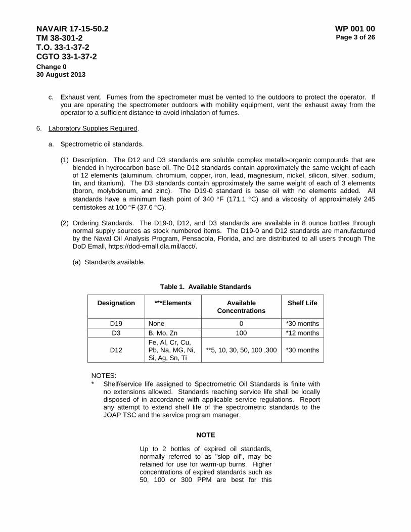
NAVAIR 17-15-50.2 TM 38-301-2 T.O. 33-1-37-2 CGTO 33-1-37-2
WP 001 00 Page 3 of 26
Change 0 30 August 2013
c. Exhaust vent. Fumes from the spectrometer must be vented to the outdoors to protect the operator. If you are operating the spectrometer outdoors with mobility equipment, vent the exhaust away from the operator to a sufficient distance to avoid inhalation of fumes.
6. Laboratory Supplies Required.
a. Spectrometric oil standards.
(1) Description. The D12 and D3 standards are soluble complex metallo-organic compounds that are blended in hydrocarbon base oil. The D12 standards contain approximately the same weight of each of 12 elements (aluminum, chromium, copper, iron, lead, magnesium, nickel, silicon, silver, sodium, tin, and titanium). The D3 standards contain approximately the same weight of each of 3 elements (boron, molybdenum, and zinc). The D19-0 standard is base oil with no elements added. All standards have a minimum flash point of 340 °F (171.1 °C) and a viscosity of approximately 245 centistokes at 100 °F (37.6 °C).
(2) Ordering Standards. The D19-0, D12, and D3 standards are available in 8 ounce bottles through normal supply sources as stock numbered items. The D19-0 and D12 standards are manufactured by the Naval Oil Analysis Program, Pensacola, Florida, and are distributed to all users through The DoD Emall, https://dod-emall.dla.mil/acct/.
(a) Standards available.
Table 1. Available Standards
Designation ***Elements Available Concentrations
Shelf Life
D19 None 0 *30 months D3 B, Mo, Zn 100 *12 months
D12 Fe, Al, Cr, Cu, Pb, Na, MG, Ni, Si, Ag, Sn, Ti
**5, 10, 30, 50, 100 ,300 *30 months
NOTES: * Shelf/service life assigned to Spectrometric Oil Standards is finite with
no extensions allowed. Standards reaching service life shall be locally disposed of in accordance with applicable service regulations. Report any attempt to extend shelf life of the spectrometric standards to the JOAP TSC and the service program manager.
NOTE
Up to 2 bottles of expired oil standards, normally referred to as "slop oil", may be retained for use for warm-up burns. Higher concentrations of expired standards such as 50, 100 or 300 PPM are best for this

NAVAIR 17-15-50.2 TM 38-301-2 T.O. 33-1-37-2 CGTO 33-1-37-2
WP 001 00 Page 4 of 26
Change 0 30 August 2013
purpose. These slop oil bottles must be clearly marked on the label as slop oil - “for warm-up burns only" to ensure that they are not used for standardization of the spectrometer.
** The 5 PPM concentration is not applicable to AOAP laboratories.
Table 2. Elements and Their Symbols
Aluminum Al Nickel Ni Barium Ba Silicon Si Boron B Silver Ag
Cadmium Cd Sodium Na Chromium Cr Tin Sn
Copper Cu Titanium Ti Iron Fe Vanadium V Lead Pb Zinc Zn
Magnesium Mg Manganese Mn Molybdenum Mo
(b) Applicable stock number for the D19-0, D3 and D12 standards are as follows:
Table 3. Stock Numbers for Spectrometer Standards
PPM Concentration National Stock Number
0 1RM 9150-00-179-5137-SX 5 1RM 9150-01-307-3343-SX 10 1RM 9150-00-179-5145-SX 30 1RM 9150-00-179-5144-SX 50 1RM 9150-00-179-5143-SX
100 (D3) 1RM 9150-01-283-0249-SX 100 (D12) 1RM 9150-00-179-5142-SX
300 1RM 9150-00-179-5141-SX
NOTE
Only spectrometer standards obtained using the National Stock Numbers listed above are to be used.
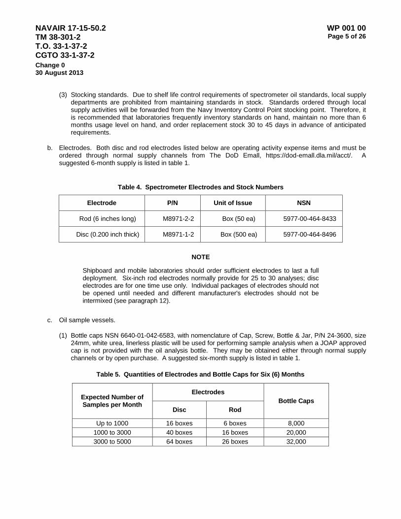
NAVAIR 17-15-50.2 TM 38-301-2 T.O. 33-1-37-2 CGTO 33-1-37-2
WP 001 00 Page 5 of 26
Change 0 30 August 2013
(3) Stocking standards. Due to shelf life control requirements of spectrometer oil standards, local supply departments are prohibited from maintaining standards in stock. Standards ordered through local supply activities will be forwarded from the Navy Inventory Control Point stocking point. Therefore, it is recommended that laboratories frequently inventory standards on hand, maintain no more than 6 months usage level on hand, and order replacement stock 30 to 45 days in advance of anticipated requirements.
b. Electrodes. Both disc and rod electrodes listed below are operating activity expense items and must be ordered through normal supply channels from The DoD Emall, https://dod-emall.dla.mil/acct/. A suggested 6-month supply is listed in table 1.
Table 4. Spectrometer Electrodes and Stock Numbers
Electrode P/N Unit of Issue NSN
Rod (6 inches long) M8971-2-2 Box (50 ea) 5977-00-464-8433
Disc (0.200 inch thick) M8971-1-2 Box (500 ea) 5977-00-464-8496
NOTE
Shipboard and mobile laboratories should order sufficient electrodes to last a full deployment. Six-inch rod electrodes normally provide for 25 to 30 analyses; disc electrodes are for one time use only. Individual packages of electrodes should not be opened until needed and different manufacturer's electrodes should not be intermixed (see paragraph 12).
c. Oil sample vessels.
(1) Bottle caps NSN 6640-01-042-6583, with nomenclature of Cap, Screw, Bottle & Jar, P/N 24-3600, size 24mm, white urea, linerless plastic will be used for performing sample analysis when a JOAP approved cap is not provided with the oil analysis bottle. They may be obtained either through normal supply channels or by open purchase. A suggested six-month supply is listed in table 1.
Table 5. Quantities of Electrodes and Bottle Caps for Six (6) Months
Expected Number of Samples per Month
Electrodes Bottle Caps
Disc Rod
Up to 1000 16 boxes 6 boxes 8,000 1000 to 3000 40 boxes 16 boxes 20,000 3000 to 5000 64 boxes 26 boxes 32,000
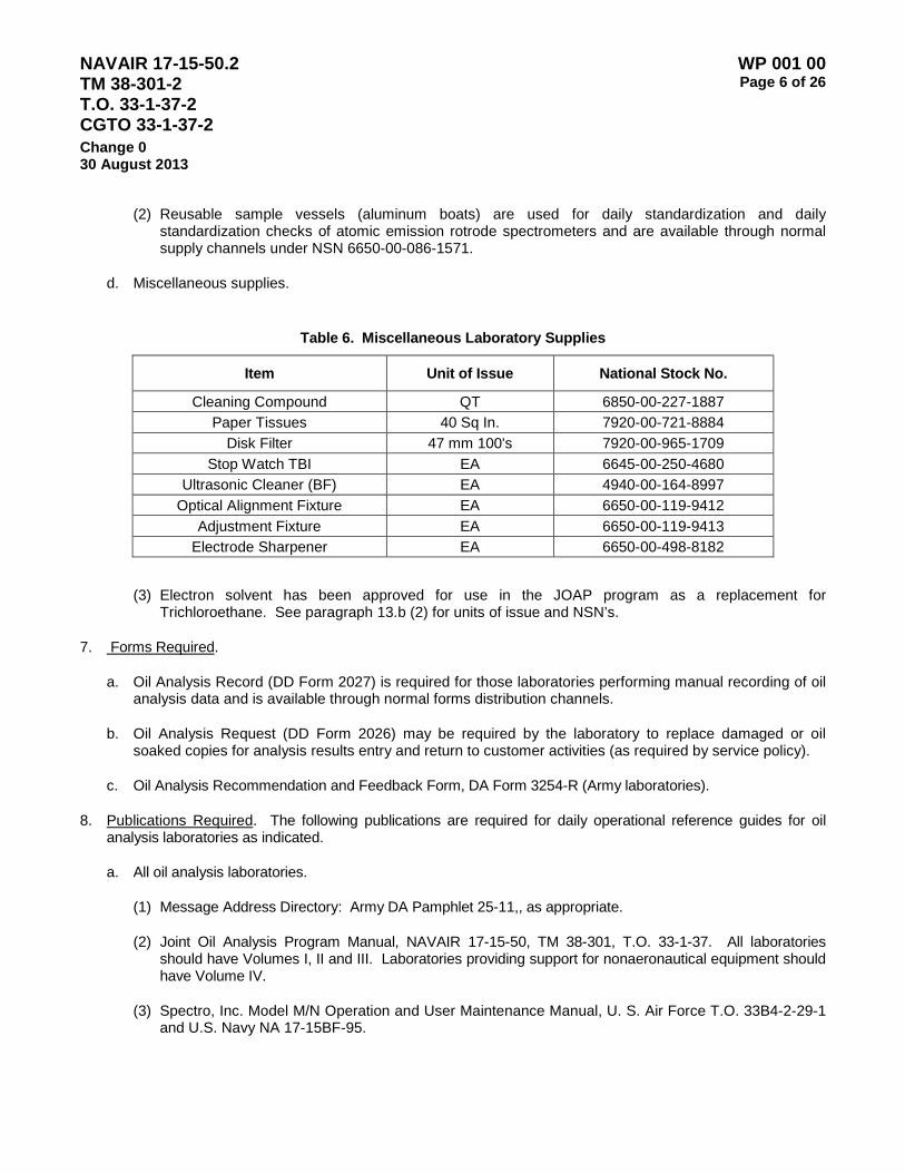
NAVAIR 17-15-50.2 TM 38-301-2 T.O. 33-1-37-2 CGTO 33-1-37-2
WP 001 00 Page 6 of 26
Change 0 30 August 2013
(2) Reusable sample vessels (aluminum boats) are used for daily standardization and daily standardization checks of atomic emission rotrode spectrometers and are available through normal supply channels under NSN 6650-00-086-1571.
d. Miscellaneous supplies.
Table 6. Miscellaneous Laboratory Supplies
Item Unit of Issue National Stock No.
Cleaning Compound QT 6850-00-227-1887 Paper Tissues 40 Sq In. 7920-00-721-8884
Disk Filter 47 mm 100's 7920-00-965-1709 Stop Watch TBI EA 6645-00-250-4680
Ultrasonic Cleaner (BF) EA 4940-00-164-8997 Optical Alignment Fixture EA 6650-00-119-9412
Adjustment Fixture EA 6650-00-119-9413 Electrode Sharpener EA 6650-00-498-8182
(3) Electron solvent has been approved for use in the JOAP program as a replacement for Trichloroethane. See paragraph 13.b (2) for units of issue and NSN’s.
7. Forms Required.
a. Oil Analysis Record (DD Form 2027) is required for those laboratories performing manual recording of oil analysis data and is available through normal forms distribution channels.
b. Oil Analysis Request (DD Form 2026) may be required by the laboratory to replace damaged or oil soaked copies for analysis results entry and return to customer activities (as required by service policy).
c. Oil Analysis Recommendation and Feedback Form, DA Form 3254-R (Army laboratories).
8. Publications Required. The following publications are required for daily operational reference guides for oil analysis laboratories as indicated.
a. All oil analysis laboratories.
(1) Message Address Directory: Army DA Pamphlet 25-11,, as appropriate.
(2) Joint Oil Analysis Program Manual, NAVAIR 17-15-50, TM 38-301, T.O. 33-1-37. All laboratories should have Volumes I, II and III. Laboratories providing support for nonaeronautical equipment should have Volume IV.
(3) Spectro, Inc. Model M/N Operation and User Maintenance Manual, U. S. Air Force T.O. 33B4-2-29-1 and U.S. Navy NA 17-15BF-95.

NAVAIR 17-15-50.2 TM 38-301-2 T.O. 33-1-37-2 CGTO 33-1-37-2
WP 001 00 Page 7 of 26
Change 0 30 August 2013
9. Sample Processing.
a. Test and evaluation priority shall be as follows:
(1) Special aeronautical.
(2) Routine aeronautical.
(3) Special nonaeronautical.
(4) Routine nonaeronautical.
b. Each laboratory shall analyze samples, evaluate results, and transmit recommendations to the customer as soon as possible during normal working hours on a non-reimbursable basis. Aeronautical samples shall be processed within 24 clock hours of receipt and nonaeronautical samples within 72 clock hours of receipt, weekends and holidays excluded. Equipment specific variations to these time requirements are noted in the specific equipment tables in volumes III and IV.
c. If delays are expected in processing priority samples, the laboratory shall notify the customer as soon as possible.
d. The laboratory shall normally request a special sample for verification of analysis prior to a recommendation for maintenance action.
10. Disposal of Oil Sample Bottles and Caps. All oil sample bottles (glass and plastic), bottle caps, plastic tubing and unused oil shall be segregated for disposal and disposed of in accordance with local base requirements.
11. Spectrometer Preparation and Operation. Spectrometers shall be operated in accordance with the applicable manual (See paragraph 9 above). This paragraph provides basic policies and minimum procedures related to the operating procedures of specific instruction. All spectrometers require preliminary preparation prior to operational use (spectrometers that are being used that flying day). Daily standardization checks in accordance with procedures identified in the manuals for each spectrometer shall be performed once each day prior to operation (As a minimum Air Force labs will perform a daily standardization prior to each shift.) If the daily standardization check is out of allowable tolerances, a complete standardization shall be performed in accordance with the applicable spectrometer manual. A complete standardization shall be performed at least once each week. Correct frequency, or breaks per half cycle, is essential for repeatable results. Those spectrometers that do not have any automatic frequency adjustment (Spectro M and M/N) shall be checked at least once every 2000 burns. Periodic standardization checks shall be made throughout the operational period. At a minimum, these checks will be made when switching from analysis of aeronautical to non-aeronautical samples or vice versa. The following instructions also apply:
a. All laboratories. Personnel shall not smoke, eat, or drink in close proximity to oil analysis equipment, sample preparation areas, or ADP equipment. Cell phone use is not allowed while operating laboratory analytical or ADP equipment. Laboratories shall operate observing recommended environmental requirements (such as temperature and humidity) including adequate overhead illumination and ventilation so as to safely and accurately process samples.

NAVAIR 17-15-50.2 TM 38-301-2 T.O. 33-1-37-2 CGTO 33-1-37-2
WP 001 00 Page 8 of 26
Change 0 30 August 2013
b. Atomic Emission Laboratories.
(1) Electrodes. An analysis obtained on a sample using one manufacturer’s electrodes will frequently vary from results obtained on the same sample when using electrodes from another manufacturer. Therefore, when a change is made from one manufacturer’s to another manufacturer’s electrodes (either rod, disc, or both), or a change in lot or batch number of the same manufacturer occurs, a daily standardization check must be performed using the new electrodes before continuing operations. Also, ensure that the operator performs a disc-offset procedure if this procedure is required for the spectrometer in use (typically Spectro, Inc. Model M and M/N). Refer to the spectrometer manual.
(a) Rod electrodes will be sharpened only on one end after each burn. The sharpening process must remove all contamination from the previous burn. Contamination is readily visible as stains/discolorations on the flat face and the sides of the electrode and must be completely removed in order to avoid contamination of subsequent analysis burns. The rsharpened end should have a smooth, polished appearance and the slight point on the sharpened end must be geometrically centered. Rod electrodes must not be handled by the sharpened end in order to avoid contamination. Place tape around the end of the rod electrode which will be handled by the operatory to avoid contamination. Electrodes will be keep in a contamination free container while not in use.
(b) Disc electrodes are one time use only and must be discarded after each sample analysis. Electrodes will not be picked up or touched with the hands but will always be handled with a tissue to avoid the possibility of contamination. Discs will not be poured out in an open container, but will be left in the original container until ready for use. Dropped or spilled electrodes should be discarded due to the possibility of being chipped, broken or contaminated.
(2) Sample vessels. Aluminum boats (NSN 6650-00-086-1571) shall be used for standardization of the JOAP atomic emission rotrode spectrometer and for daily standardization checks. Aluminum boats are also used for any other special check or process performed prior to the analysis of used fluids; for example disk/rod offset checks and optical profiling when required. White caps (NSN 6640-01-042-6583) will be used as sample vessels for all sample analyses except when analyzing low flash point fluids. Low flash point fluids shall be analyzed using the aluminum boat with cover (NSN 6650-01-011-3472). If an insufficient amount of fluid is available for analysis to fill a cap, an aluminum boat may be used for the analysis. Aluminum boats and covers must be thoroughly cleaned before use. All caps and aluminum boats must be covered or in a contamination free container when not actively being used. Electron is the primary fluid recommended for cleaning the aluminum boats and covers. Any solvent that dissolves the oil may be used, but the solvent must have no metallic content to contaminate the boats and covers and present no serious health risk to the user or the environment. The solvent must also not affect the sample stand components when used for cleaning the sample stand. No cleaner may be used that has a flash point below 140 degrees F or one which is considered an ozone depleting substance. Consult with your local environmental personnel to ensure that any fluid that is used is completely safe and that correct usage and disposal procedures are in effect. Here is information for obtaining electron:

NAVAIR 17-15-50.2 TM 38-301-2 T.O. 33-1-37-2 CGTO 33-1-37-2
WP 001 00 Page 9 of 26
Change 0 30 August 2013
Table 7. Electron Cleaning Solvent Stock Numbers
Unit of Issue NSN 55 gallons drum 6850-01-375-5555
6 gallons 6850-01-375-5553 1 gallon 6850-01-375-5554
Aerosol spray (12 cans per box) 6850-01-371-8048 Pump spray (12 per box) 6850-01-371-8049
(3) Sample excitation stand cleaning. The excitation stand area must be kept clean in order to obtain accurate and repeatable analyses. Dirt and oil, in addition to distorting sample results, may also cause high-voltage arcing, which may result in damage to the instrument. All personnel must adhere to the cleaning procedures and schedules given in the applicable instrument owner’s manual. Refer to page 6 of this work package for the applicable manual numbers.
12. Data Recording, Processing, and Warehousing. Each Service has unique software and data handling processes and procedures. Refer to WP 002, WP 003, and WP 004 as applicable for the appropriate requirements, information and procedures.
a. The US Army data is processed and warehoused by the U.S. Army Program Management office at Redstone Arsenal, Huntsville, AL. The U.S. Navy data is processed and warehoused by the U.S. Navy Program Management office at Pensacola NAS, Pensacola, FL. The US Air Force data is processed and warehoused by the US Air Force Program management Office at Tinker AFB, Oklahoma City, Ok.
(1) Laboratories shall submit data to their respective service database as directed by the Service Program Manager or as contained in Volume I, Work Package 004 00.
(2) Each Service Program manager is responsible for routine data transfer to the other services.
NOTE
JOAP laboratory personnel are responsible for ensuring that all processed oil analysis results are entered into the applicable service database. This includes assigned, temporarily assigned, transient, and deployed assets. The analysis information shall be supplied to the owning organization or home base location for database entry or update of records as applicable. Retain a copy of the analysis data until receipt is confirmed to ensure that no analysis data is lost.
Army only: The AOAP Program Manager will provide technical assistance and initiate corrective software program changes to the Oil Analysis Standard Interservice System (OASIS) laboratory operating system. If OASIS software support is required, contact the AOAP Manager as follows:
ARMY OIL ANALYSIS PROGRAM MANAGEMENT OFFICE USAMC LOGISTICS SUPPORT ACTIVITY ATTN AMXLS-GO BUILDING 3661 REDSTONE ARSENAL AL 35898-7466 AOAP Hot Line DSN: 645-0869 / (256) 955-0869 Data Facsimile: 746-9344 / (256) 876-9344 DDN address:[email protected]

NAVAIR 17-15-50.2 TM 38-301-2 T.O. 33-1-37-2 CGTO 33-1-37-2
WP 001 00 Page 10 of 26
Change 0 30 August 2013
(3) Data Reports. Routine reports are produced from laboratories and from the service database. Examples of some of the reports available are included in Volume II Work Packages 002 (Army), 003 (Navy) and 004 (Army).
b. Automated laboratories. Detailed information concerning automated systems to access the computer file data and for entry of variable sample data into the computer files.
(1) The DD Form 2026 is used as a source document for basic information to access the computer file data and for entry of variable sample data into the computer files. Entry of sample analysis data on the DD Form 2026 by the laboratory is not required unless required by individual service policy for return of the DD Form 2026 to the customer.
(2) DD Form 2027 is not normally used by automated laboratories unless required for backup or temporary records in the event of automated system failure.
(3) The requirements for assignment of sample numbers by service activities is the same as that specified in paragraph 14.c. for non-automated laboratories.
c. Non-automated laboratories (All AF labs). The following information is for use by those non-automated laboratories required to transmit manually accumulated data into the JOAP database and may be directed for use by other service program managers for their automated laboratories experiencing ADP equipment failure.
(1) DD Form 2026 is used as a source document to locate existing DD Form 2027 and complete the variable data section or to initiate new DD Form 2027. The DD Form 2026 is also used by Air Force non-automated laboratories for submission of data for entry into the JOAP data base (see WP 004 03 for specific Air Force data submission instructions), and may be directed for use by other service program managers in appropriate circumstances.
(2) DD Form 2027 (Figure 1) is used as an historical record of equipment monitored. Non-Air Force activities that are not designated to transfer data to the data base shall complete DD Form 2027 using information from the DD Form 2026 and laboratory analysis data and retain DD Form 2027 on file as the historical record for each item of equipment monitored. These laboratories may use either coded or plain language data entries, whichever is locally desired. Laboratories will comply with individual service directives for sending non-automated data into the JOAP database.
(3) Data from the DD Form 2026 are transferred to the DD Form 2027 as follows:
(a) Permanent data section: The information for this section is provided by the oil analysis request (DD Form 2026). This data once entered on the DD Form 2027, rarely changes but should be verified at the time of each subsequent data entry.
NOTE
When instructions for a data entry item specify, “leave blank”, laboratory personnel may use these data entry blocks for any purpose desired locally. Each laboratory supervisor will determine which, if any, of the data entry blocks will be used locally and for what purpose.
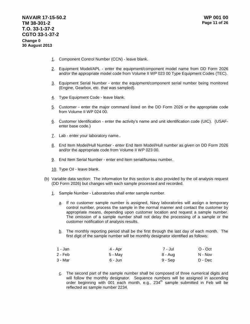
NAVAIR 17-15-50.2 TM 38-301-2 T.O. 33-1-37-2 CGTO 33-1-37-2
WP 001 00 Page 11 of 26
Change 0 30 August 2013
1. Component Control Number (CCN) - leave blank.
2. Equipment Model/APL - enter the equipment/component model name from DD Form 2026 and/or the appropriate model code from Volume II WP 023 00 Type Equipment Codes (TEC).
3. Equipment Serial Number - enter the equipment/component serial number being monitored (Engine, Gearbox, etc. that was sampled).
4. Type Equipment Code - leave blank.
5. Customer - enter the major command listed on the DD Form 2026 or the appropriate code from Volume II WP 024 00.
6. Customer Identification - enter the activity’s name and unit identification code (UIC). (USAF-enter base code.)
7. Lab - enter your laboratory name..
8. End Item Model/Hull Number - enter End Item Model/Hull number as given on DD Form 2026 and/or the appropriate code from Volume II WP 023 00.
9. End Item Serial Number - enter end item serial/bureau number.
10. Type Oil - leave blank.
(b) Variable data section: The information for this section is also provided by the oil analysis request (DD Form 2026) but changes with each sample processed and recorded.
1. Sample Number - Laboratories shall enter sample number.
a. If no customer sample number is assigned, Navy laboratories will assign a temporary control number, process the sample in the normal manner and contact the customer by appropriate means, depending upon customer location and request a sample number. The omission of a sample number shall not delay the processing of a sample or the customer notification of analysis results.
b. The monthly reporting period shall be the first through the last day of each month. The first digit of the sample number will be monthly designator identified as follows:
1 - Jan 4 - Apr 7 - Jul O - Oct 2 - Feb 5 - May 8 - Aug N - Nov 3 - Mar 6 - Jun 9 - Sep D - Dec
c. The second part of the sample number shall be composed of three numerical digits and will follow the monthly designator. Sequence numbers will be assigned in ascending order beginning with 001 each month, e.g., 234th sample submitted in Feb will be reflected as sample number 2234.

NAVAIR 17-15-50.2 TM 38-301-2 T.O. 33-1-37-2 CGTO 33-1-37-2
WP 001 00 Page 12 of 26
Change 0 30 August 2013
2. Data Index - USN leave blank. USAF leave blank for routine documentation. For file maintenance actions, see Appendices A and E.
3. Date Sample Analyzed - enter Julian date sample analyzed.
4. Response/Turn Around Time - enter the number of days in transit as calculated by subtracting the date the sample was taken from the date the sample was analyzed. Air Force laboratories will enter the total sample response time in whole hours to include elapsed hours from the time that the sample was taken to the time that the laboratory completed sample processing and issues laboratory recommendation. (Army laboratories - leave blank.)
5. Last Lab Recommendation - leave blank.
6. Hours/Miles Since Overhaul - enter the number of hours/miles since new or overhauled as applicable
7. Hours/Miles Oil Change - enter the number of hours/miles since oil change.
8. Reason for Sample - enter the appropriate reason sample submitted code from WP 025 00.
FIGURE 1. Oil Analysis Record (DD Form 2027)

NAVAIR 17-15-50.2 TM 38-301-2 T.O. 33-1-37-2 CGTO 33-1-37-2
WP 001 00 Page 13 of 26
Change 0 30 August 2013
NOTE
If the DD 2026 reports that oil was added since the last sample data was submitted, use wear-metal columns Ba, Cd, and Mn to record the unit of measurement in Ounces (O), Pints (P), Quarts (Q), or Gallons (G), the numerical quantity of oil added, and the oil consumption rate in unit quantity per hour. (For example, Q1-0.5; i.e., 1 quart of oil added and a consumption rate of 0.5 quarts per hour.) To determine the oil consumption rate, compute the operating hours between oil additions by subtracting previously reported oil addition time since oil change (TSOC) or time since overhaul (TSO) from latest oil addition TSOC or TSO. Divide the reported quantity of oil added by the operating hours calculated above for the oil consumption rate per operative hour. The oil consumption rate trend provides additional information to aid the laboratory evaluator and maintenance personnel in evaluating equipment condition. The individual taking the sample must ensure that all oil added since the last sample (regardless of the number of hours between samples) is documented on the DD2026, including oil added after the current sample is taken so that the rate of oil usage can be correctly determined. For example, over the course of 100 hours between samples, oil has been added 8 times and added after the current sample for a total amount of 1 quart.
(c) Post analysis data:
1. Validation - this block is normally left blank. However, it may be used to identify the laboratory operator/evaluator for laboratory management purposes.
2. Laboratory Recommendation - after laboratory evaluation of sample results, enter the appropriate recommendation code from WP 025 00.
(d) Feedback data (if applicable):
1. Action Taken - enter the appropriate action taken code from Volume II WP 025 00.
2. Discrepant Item - enter the appropriate discrepant item code from Volume II WP 025 00.
3. How Malfunctioned - enter the appropriate how malfunctioned code from Volume II WP 025 00.
4. How Found - enter the appropriate how found code from Volume II WP 025 00.
13. Analytical Data Evaluation. Techniques for evaluating analytical results, evaluation criteria, and the methodology for establishing criteria are contained in Volumes III and IV.

NAVAIR 17-15-50.2 TM 38-301-2 T.O. 33-1-37-2 CGTO 33-1-37-2
WP 001 00 Page 14 of 26
Change 0 30 August 2013
14. Response to Customers.
a. Response requirements. Each laboratory is required to provide analysis results, recommendations, and additional information, when applicable, to customers as shown below. Shorter laboratory response time requirements than those specified in paragraph 11 may be assigned by parent program management offices since response time requirements vary according to type equipment, operational and mission differences and individual service requirements. Equipment specific variations to these time requirements are noted in the specific equipment tables in Volumes III and IV.
(1) Army and Navy. Upon receipt, laboratory personnel shall stamp the DD Form 2026 with a sample number and the date received.
(2) The Army requires the processed DD Form 2026/DA Form 5991-E, Oil Analysis Request, to be returned to the submitting Army unit personnel.
(a) Laboratory personnel shall circle in red all incomplete or obviously incorrect entries on DD Form 2026 submitted with samples and a copy of the incorrect or incomplete DD 2026 shall be returned to the customer’s QA for corrective action. Laboratories shall return the processed DD Form 2026 stamped with either PROCESSED (date) NORMAL RESULTS” or “PROCESSED (date) ABNORMAL RESULTS” to all customers. The laboratory shall annotate the DD Form 2026 with the laboratory recommendation and if the recommendation is other than normal with enough information to identify what was abnormal. For example “High iron” or “low viscosity.” At a minimum. DD Form 2026 will be returned once a week.
(b) Each laboratory is required to provide information to customers that will enable the customer to ensure that all samples taken were received and analyzed by the laboratory. For samples with normal results, return of the processed DD Form 2026 will serve as notification of completion of sample analysis. For samples with abnormal results, the laboratory shall advise the owning unit of the laboratory recommendation either in person or by telephone within 24 clock hours of sample receipt for aeronautical samples and within 72 clock hours of sample receipt for nonaeronautical samples, weekends and holidays excluded.
(c) Laboratories shall provide units with Oil Analysis Standard Interservice System reports as required.
At a minimum, Army laboratories shall provide the Components enrolled in AOAP and the Resample and Type Recommendation Reports monthly to all using units.
(d) Army only. Requests for samples and oil changes shall be made on DD Form 2026. Recommendations for maintenance actions shall be made on DA Form 3254-R, Oil Analysis Recommendation and Feedback. Once initial contact is made in person or by telephone, the laboratory shall follow up with a DA Form 3254-R for all on-post units and for off-post nonaeronautical Reserve and National Guard units. For aeronautical Reserve and National Guard units and for off-post active Army units (aeronautical and non-aeronautical) the laboratory shall follow up initial contact with a priority message confirming initial contact and a DA Form 3254-R by mail. The DA Form 3254-R shall be forwarded within 24 clock hours following the initial contact. A DA Form 3254-R and instructions for laboratory preparation of the form are in WP 002 03.

NAVAIR 17-15-50.2 TM 38-301-2 T.O. 33-1-37-2 CGTO 33-1-37-2
WP 001 00 Page 15 of 26
Change 0 30 August 2013
(2) Air Force laboratories and Navy non-aviation samples do not require the processed DD Form 2026 to be returned. They should ensure that the customer is notified of the receipt and processing of all samples. Navy laboratories shall also be responsible for providing adequate analysis information to the customer, as directed by responsible authority, to enable the customer to comply with the requirement imposed by OPNAVINST 4790.2G to maintain records of oil analysis results to highlight equipment trends.
(3) Interservice response Requirements. Laboratories performing interservice fluid analysis service shall comply with the requirements of the customer’s parent service regarding sample response unless alternate response procedural agreements between services are reached.
(4) Samples requiring amplified response. All laboratories must provide sample analysis results, including laboratory recommendation information when applicable, to the customer activity for all types of samples listed below:
(a) All special samples.
(b) All samples for which the analysis indicates possible discrepancy.
(c) All samples suspected to be invalid.
(d) All samples for which response is specifically requested by the operating activity in special circumstances.
b. Content and terminology. Each response shall contain the following information:
(1) Equipment model and serial number and end item model and serial number. This information is provided by the customer on the Oil Analysis Request (DD Form 2026).
(2) Sample analysis. The sample analysis shall be reported as normal, marginal, high, or abnormal for individual metal content. In cases where there are no limits specified in Volumes III or IV just provide the data.
(3) Date sample Taken. As provided on DD Form 2026.
(4) Recommendations. Each response shall contain the complete recommendation description corresponding to the applicable recommendation code.
NOTE
Laboratory recommendations are indeed only recommendations. It is the customer’s responsibility to take appropriate corrective action. If a disagreement between the laboratory and customer arises concerning corrective action, the discrepancy should be entered in the equipment forms by laboratory personnel and corrective action taken, if any, entered by the customer.

NAVAIR 17-15-50.2 TM 38-301-2 T.O. 33-1-37-2 CGTO 33-1-37-2
WP 001 00 Page 16 of 26
Change 0 30 August 2013
c. Method of response. Each laboratory response shall be prepared and delivered as follows:
(1) Results involving operational/flight safety. Whenever analysis of any sample results in a laboratory determination that operational/flight safety is affected, the laboratory shall immediately provide detailed Information to the customer by telephone, when possible, followed by priority message (or memorandum for on base responses if desired) for confirmation of results and recommendations.
(2) Results not involving operational/flight safety. Whenever analysis of a sample results in a recommendation requiring the customer to take action, but does not involve operational/flight safety, reports shall be made verbally followed by a memorandum report for on base/post customers (except in cases where Information copies of official notification correspondence are required by higher commands) and by message, speed letter or letter, as appropriate for off base/post customers. All sample results shall be reported to the customer within 3 working days.
(3) Message format. A recommended format for a priority message for use in reporting analysis results Involving operational/flight safety follows:
FROM: LABORATORY
TO: CUSTOMER
INFO: SERVICE OIL ANALYSIS PROGRAM MANAGEMENT OFFICE
COGNIZANT FIELD ACTIVITY (USN) /ITEM MANAGER (USAF)
(Engine/component removal recommendations only)
TYCOM (USN) /MAJOR COMMAND (USA, USAF)
(Engine/component removal recommendations only)
OTHER INFO ADDRESSEES (as directed by individual service requirements)
UNCLAS
SUBJ: JOAP OIL SAMPLE ANALYSIS REPORT
REF: (A) NA 17 15 50/TM 38 301/T.O. 33 1 37
1 IAW REF (A) FOLLOWING REPORT SUBMITTED
a. SAMPLE NUMBER (if assigned) AND TYPE (routine/ Special).
b. DATE SAMPLE TAKEN.
c. END ITEM IDENTIFICATION (serial/indent number).
d. EQUIPMENT MODEL AND SERIAL NUMBER.
e. SAMPLE ANALYSIS RESULTS (normal, marginal, high, Abnormal for specific elements)
f. RECOMMENDATIONS (use plain language corresponding to specific recommendation codes) RECOMMEND DO NOT FLY, DO NOT CHANGE OIL, SUBMIT CHECK SAMPLE ASAP, ETC.

NAVAIR 17-15-50.2 TM 38-301-2 T.O. 33-1-37-2 CGTO 33-1-37-2
WP 001 00 Page 17 of 26
Change 0 30 August 2013
(4) Laboratory responses to contractor customers requiring oil analysis support in support of a contract with a component of DOD shall contain the same information as responses made to military operating activity customers.
15. Transfer of Oil Analysis Records. Any time that an oil analysis customer relocates, either deployed or permanently, and oil analysis services are required at the new location, the transfer of workload and provision of services shall be handled through the normal chain of command in order to ensure orderly transfer of support. Unusual problems encountered should be referred to the appropriate service oil analysis program management office for resolution.
a. Transient equipment records. Transient customers are responsible for obtaining complete oil analysis records for their equipment from the losing laboratory and for delivery of the records to the gaining laboratory at the new operating site. If sufficient time is not available to comply with these procedures prior to departure, the customer shall notify the losing laboratory concerning the relocation and the losing laboratory shall mail all required oil analysis records to the gaining laboratory.
b. Permanent relocation/temporary deployment. Whenever the oil analysis workload is transferred from one laboratory to another due to customer transfer, the following instructions apply:
(1) Transferring activity (Customer). The customer activity is responsible for notifying the home base (supporting) oil analysis laboratory concerning transfer/deployment schedules in advance of departure. Advance notice is required in order to provide the laboratory sufficient time for orderly processing of records for transfer to the new supporting laboratory to avoid disruption in equipment oil analysis monitoring schedules.
(2) Transferring/losing laboratory. The losing laboratory will forward equipment oil analysis records directly to the gaining laboratory unless directed otherwise by competent authority. The losing laboratory shall ensure that each equipment record transferred is complete, accurate and legible.
(a) When both the losing and gaining laboratories are equipped with appropriate automated systems the record transfer may be accomplished using ADP products in accordance with instructions provided by the appropriate service program management office.
(b) When only one or neither laboratory is equipped with an automated data system, a copy of records must be made for transfer. Either a hardcopy computer record printout or copies of DD Form 2027, refer to figure 1, may be used, depending upon the losing laboratory capabilities.
(c) The following actions will be taken by transferring/losing laboratories:
1. Customer temporary deployment.
a. Retain original oil analysis records.
b. Forward copies of records to gaining laboratories.
c. Update or replace original records upon return of customer/equipment and notify deployment site laboratory of records receipt.
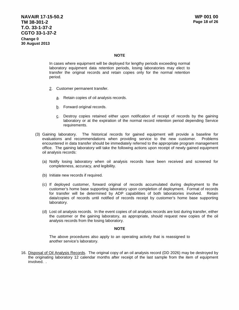
NAVAIR 17-15-50.2 TM 38-301-2 T.O. 33-1-37-2 CGTO 33-1-37-2
WP 001 00 Page 18 of 26
Change 0 30 August 2013
NOTE
In cases where equipment will be deployed for lengthy periods exceeding normal laboratory equipment data retention periods, losing laboratories may elect to transfer the original records and retain copies only for the normal retention period.
2. Customer permanent transfer.
a. Retain copies of oil analysis records.
b. Forward original records.
c. Destroy copies retained either upon notification of receipt of records by the gaining laboratory or at the expiration of the normal record retention period depending Service requirements.
(3) Gaining laboratory. The historical records for gained equipment will provide a baseline for evaluations and recommendations when providing service to the new customer. Problems encountered in data transfer should be immediately referred to the appropriate program management office. The gaining laboratory will take the following actions upon receipt of newly gained equipment oil analysis records:
(a) Notify losing laboratory when oil analysis records have been received and screened for completeness, accuracy, and legibility.
(b) Initiate new records if required.
(c) If deployed customer, forward original of records accumulated during deployment to the customer’s home base supporting laboratory upon completion of deployment. Format of records for transfer will be determined by ADP capabilities of both laboratories involved. Retain data/copies of records until notified of records receipt by customer’s home base supporting laboratory.
(d) Lost oil analysis records. In the event copies of oil analysis records are lost during transfer, either the customer or the gaining laboratory, as appropriate, should request new copies of the oil analysis records from the losing laboratory.
NOTE
The above procedures also apply to an operating activity that is reassigned to another service’s laboratory.
16. Disposal of Oil Analysis Records. The original copy of an oil analysis record (DD 2026) may be destroyed by the originating laboratory 12 calendar months after receipt of the last sample from the item of equipment involved. .
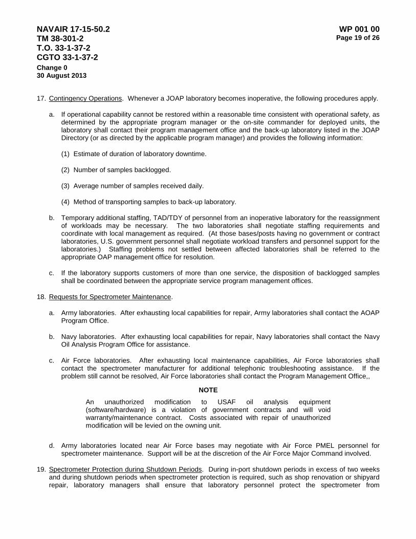
NAVAIR 17-15-50.2 TM 38-301-2 T.O. 33-1-37-2 CGTO 33-1-37-2
WP 001 00 Page 19 of 26
Change 0 30 August 2013
17. Contingency Operations. Whenever a JOAP laboratory becomes inoperative, the following procedures apply.
a. If operational capability cannot be restored within a reasonable time consistent with operational safety, as determined by the appropriate program manager or the on-site commander for deployed units, the laboratory shall contact their program management office and the back-up laboratory listed in the JOAP Directory (or as directed by the applicable program manager) and provides the following information:
(1) Estimate of duration of laboratory downtime.
(2) Number of samples backlogged.
(3) Average number of samples received daily.
(4) Method of transporting samples to back-up laboratory.
b. Temporary additional staffing, TAD/TDY of personnel from an inoperative laboratory for the reassignment of workloads may be necessary. The two laboratories shall negotiate staffing requirements and coordinate with local management as required. (At those bases/posts having no government or contract laboratories, U.S. government personnel shall negotiate workload transfers and personnel support for the laboratories.) Staffing problems not settled between affected laboratories shall be referred to the appropriate OAP management office for resolution.
c. If the laboratory supports customers of more than one service, the disposition of backlogged samples shall be coordinated between the appropriate service program management offices.
18. Requests for Spectrometer Maintenance.
a. Army laboratories. After exhausting local capabilities for repair, Army laboratories shall contact the AOAP Program Office.
b. Navy laboratories. After exhausting local capabilities for repair, Navy laboratories shall contact the Navy Oil Analysis Program Office for assistance.
c. Air Force laboratories. After exhausting local maintenance capabilities, Air Force laboratories shall contact the spectrometer manufacturer for additional telephonic troubleshooting assistance. If the problem still cannot be resolved, Air Force laboratories shall contact the Program Management Office,,
NOTE An unauthorized modification to USAF oil analysis equipment (software/hardware) is a violation of government contracts and will void warranty/maintenance contract. Costs associated with repair of unauthorized modification will be levied on the owning unit.
d. Army laboratories located near Air Force bases may negotiate with Air Force PMEL personnel for spectrometer maintenance. Support will be at the discretion of the Air Force Major Command involved.
19. Spectrometer Protection during Shutdown Periods. During in-port shutdown periods in excess of two weeks and during shutdown periods when spectrometer protection is required, such as shop renovation or shipyard repair, laboratory managers shall ensure that laboratory personnel protect the spectrometer from
NAVAIR 17-15-50.2 TM 38-301-2 T.O. 33-1-37-2 CGTO 33-1-37-2
WP 001 00 Page 20 of 26
Change 0 30 August 2013
contamination (dust, paint chips, moisture, etc.). A plastic covering, taped to form a complete barrier is recommended for this purpose.
20. JOAP Certification and Correlation Programs. The JOAP Certification and Correlation Programs are primary elements of the JOAP quality assurance initiative to ensure standardization of procedures and quality of oil analysis by the JOAP laboratories. Follow the specific spectrometer operators’ manual for any additional special standardization recommendations/requirements prior to the analysis of correlation samples such as optical alignment or a check of the source frequency using a test meter or an oscilloscope. Participation in these programs is mandatory for all atomic emission rotrode spectrometer oil analysis laboratories, organic or under contract to a US military service for analyzing used oils from U.S. government equipment.
a. Certification program. Based upon laboratory facilities, personnel qualifications, and JOAP Correlation Program scores, laboratory spectrometers are categorized as certified or uncertified.
(1) Certified laboratories are authorized to provide oil analysis support to all authorized and approved customers, intraservice and interservice, as well as other DoD authorized customers. Uncertified laboratories are prohibited from providing oil analysis services to any customers unless the appropriate service program. Management office grants a waiver. This waiver must be in writing and shall normally limit the laboratory to intraservice support. A waiver granting authority for interservice support shall be supported by written concurrence of the program manager of the other supported service(s) on file with the program management office granting the waiver.
(2) The JOAP Certification Program is described in detail in Volume I WP 004 00.
b. Correlation program.
(1) If a laboratory receives damaged correlation samples or does not receive samples by the 15th of the month, the laboratory shall notify [email protected] of the problem immediately.
(2) Perform complete spectrometer standardization. Immediately following the standardization, perform a daily standardization check with at least three standards prior to correlation samples analysis to ensure that the standardization was successful. If the results are not within the required tolerances, repeat the complete spectrometer standardization until the daily standardization checks are acceptable.
NOTE
Correlation printouts, including all standardization data and left over correlation oil, shall be retained for three months. This information is vital for troubleshooting instruments that score low in the program. The Program Managers may also request printouts as a quality assurance check.
(3) Ensure that the samples are analyzed on the spectrometer whose serial number is on the mailing label. Follow the spectrometer operating manual for additional special standardization recommendations/requirements prior to the analysis of correlation samples such as optical alignment or a check of the source frequency using a test meter or an oscilloscope.
(4) Shake each correlation sample vigorously for one minute by hand just prior to analysis.
(5) Analyze each sample three (3) times and average the results.

NAVAIR 17-15-50.2 TM 38-301-2 T.O. 33-1-37-2 CGTO 33-1-37-2
WP 001 00 Page 21 of 26
Change 0 30 August 2013
(6) Properly discard of samples after analyses, do NOT pour samples back into bottles for later analysis.
(7) Report results on the MS Word template via e-mail. Figure 2 is an example of a completed report template ready for submission to [email protected] as an attachment to the email message. A copy of the MS Word report template may be obtained from your respective OA program manager.
Examples: 5.5 PPM = 6, 4.4 PPM = 4.
(8) Record “0” if a zero reading is obtained.
(9) Record R/M if one or more elements are inoperative.
(10) Submit results to the OAPCORR team as soon as possible after receipt of the samples, but within 5 duty days. Current month results are to be submitted by the 21st of the month. Results received after the 21st will not be used to help calculate the trimmed mean. JOAP certified laboratories should ensure that results from the previous month are received prior to submitting current month results. If a low score is achieved, then the problem can then be hopefully resolved prior to submitting additional results. Results are to be sent by email to [email protected]. If sending data by e-mail, be sure to attach the data using the standard form supplied.
(11) Comply with any other special instructions received with the correlation samples.
(12) Score computation.
(a) General. Correlation scores for all participating laboratory spectrometers are based on reproducibility 1 and reproducibility 2 results. A correlation test results report is sent each month for all spectrometers enrolled in the program. If either reproducibility 1 (R1) or reproducibility 2 (R2) fails the criteria for any of the required elements, points are subtracted. Each sample pair accounts for 50 possible points for a total of 100 points.
(b) Late results.
1. Non-submission (NS). If the score sheet indicates N/S for the current month and results were submitted, contact the [email protected] as soon as possible. If results were not submitted, please submit them as soon as possible indicating on the email SUBJECT line LATE. For JOAP Certified labs, non-submission of data can jeopardize JOAP certification.
2. Reported maintenance (RM). Laboratories unable to analyze their correlation samples due to an inoperative spectrometer should report this fact to [email protected] prior to the data submission cutoff date; these laboratories will be placed in an RM status for that month. RM status laboratories must ensure repairs are expedited and that results are submitted as soon as the spectrometer is operational. Table 8 lists all JOAP fluids currently used in equipment monitored in the JOAP.
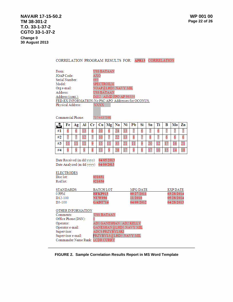
NAVAIR 17-15-50.2 TM 38-301-2 T.O. 33-1-37-2 CGTO 33-1-37-2
WP 001 00 Page 22 of 26
Change 0 30 August 2013
FIGURE 2. Sample Correlation Results Report in MS Word Template

NAVAIR 17-15-50.2 TM 38-301-2 T.O. 33-1-37-2 CGTO 33-1-37-2
WP 001 00 Page 23 of 26
Change 0 30 August 2013
NOTES
If a laboratory is unable to conduct analysis for one or more elements for a given month due to instrument malfunction and appropriate maintenance corrective actions have been initiated and reported to [email protected], an RM code will be entered in place of the score(s) that would normally be entered for the element(s). Laboratories are prohibited from analyzing oil samples for operational equipment for the element(s) for which the spectrometer was placed in an RM status. (See Volume I for additional information concerning RM status.)
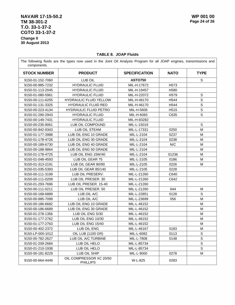
NAVAIR 17-15-50.2 TM 38-301-2 T.O. 33-1-37-2 CGTO 33-1-37-2
WP 001 00 Page 24 of 26
Change 0 30 August 2013
TABLE 8. JOAP Fluids
The following fluids are the types now used in the Joint Oil Analysis Program for all JOAP engines, transmissions and components.
STOCK NUMBER PRODUCT SPECIFICATION NATO TYPE
9150-01-152-7060 LUB OIL ASTO750 S 9150-00-985-7232 HYDRAULIC FLUID MIL-H-17672 H573 9150-01-113-2045 HYDRAULIC FLUID MIL-H-19457 H580 9150-01-080-5961 HYDRAULIC FLUID MIL-H-22072 H579 S 9150-00-111-6255 HYDRAULIC FLUID YELLOW MIL-H-46170 H544 S 9150-01-131-3325 HYDRAULIC FLUID RED MIL-H-46170 H544 S 9150-00-223-4134 HYDRAULIC FLUID PETRO MIL-H-5606 H515 S 9150-01-290-2943 HYDRAULIC FLUID MIL-H-6083 C635 S 9150-00-149-7431 HYDRAULIC FLUID MIL-H-83282 9150-00-235-9061 LUB OIL COMPOUND MIL-L-15019 S 9150-00-942-9343 LUB OIL STEAM MIL-L-17331 0250 M 9150-01-177-3988 LUB OIL ENG 10 GRADE MIL-L-2104 0Z37 M 9150-01-178-4726 LUB OIL ENG 30 GRADE MIL-L-2104 0238 M 9150-00-189-6730 LUB OIL ENG 40 GRADE MIL-L-2104 N/C M 9150-00-188-9864 LUB OIL ENG 50 GRADE MIL-L-2104 M 9150-01-178-4725 LUB OIL ENG 15W/40 MIL-L-2104 01236 M 9150-01-048-4593 LUB OIL GEAR 75 MIL-L-2105 0186 M 9150-01-313-2191 LUB OIL GEAR 80/90 MIL-L-2105 0226 M 9150-01-035-5393 LUB OIL GEAR 85/140 MIL-L-2105 0228 9150-00-111-3199 LUB OIL PRESERV. MIL-L-21260 C640 9150-00-111-0209 LUB OIL PRESER. 30 MIL-L-21260 C642 9150-01-293-7696 LUB OIL PRESER. 15-40 MIL-L-21260 9150-00-111-0211 LUB OIL PRESER. 50 MIL-L-21260 644 M 9150-00-168-6889 LUB OIL A/C MIL-L-22851 0128 S 9150-00-985-7099 LUB OIL A/C MIL-L-23699 056 M 9150-00-186-6682 LUB OIL ENG 10 GRADE MIL-L-46152 M 9150-00-186-6689 LUB OIL ENG 30 GRADE MIL-L-46152 M 9150-01-278-1356 LUB OIL ENG S/30 MIL-L-46152 M 9150-01-177-2762 LUB OIL ENG 10/30 MIL-L-46152 M 9150-01-177-2763 LUB OIL ENG 15/40 MIL-L-46152 M 9150-00-402-2372 LUB OIL ENG MIL-L-46167 0183 M 9150-LP-000-1012 OIL LUB (1100 GR) MIL-L-6082 0113 S 9150-00-782-2627 LUB OIL A/C TURBINE MIL-L-7808 0148 S 9150-01-209-2684 LUB OIL HELO MIL-L-85734 S 9150-01-210-1938 LUB OIL HELO MIL-L-85734 S 9150-00-181-8229 LUB OIL SHIP MIL-L-9000 0278 M
9150-00-664-4449 OIL COMPRESSOR XC 20/50 PHILLIPS W-L-825 0283
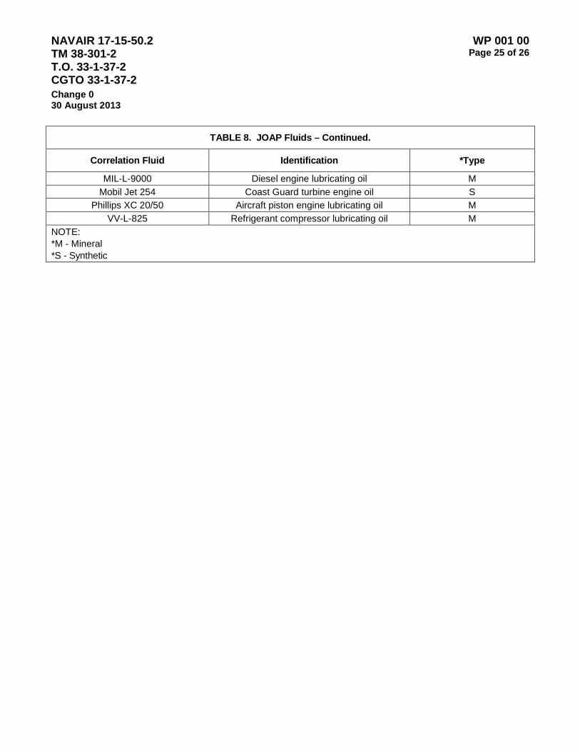
NAVAIR 17-15-50.2 TM 38-301-2 T.O. 33-1-37-2 CGTO 33-1-37-2
WP 001 00 Page 25 of 26
Change 0 30 August 2013
TABLE 8. JOAP Fluids – Continued.
Correlation Fluid Identification *Type
MIL-L-9000 Diesel engine lubricating oil M Mobil Jet 254 Coast Guard turbine engine oil S
Phillips XC 20/50 Aircraft piston engine lubricating oil M VV-L-825 Refrigerant compressor lubricating oil M
NOTE: *M - Mineral *S - Synthetic

NAVAIR 17-15-50.2 TM 38-301-2 T.O. 33-1-37-2 CGTO 33-1-37-2
WP 001 00 Page 26 of 26
Change 0 30 August 2013
This Page Intentionally Left Blank
NAVAIR 17-15-50.2 TM 38-301-2 T.O. 33-1-37-2 CGTO 33-1-37-2
WP 002 00 Page 1 of 2
Change 0 30 August 2013
ARMY OIL ANALYSIS PROGRAM LABORATORIES OPERATING REQUIREMENTS AND PROCEDURES
1. Purpose. The purpose of this work package is to establish the specific configuration requirements and operating procedures for Army Oil Analysis Program Laboratories.
2. Applicability. The provisions of this work package apply to all Army Oil Analysis Program Laboratories.
3. Work Package Structure. This Work Package is divided into three sections (subordinate work packages):
WP 03 01 – General Laboratory operating procedures and operator training requirements.
WP 03 02 – Laboratory Equipment / Configuration Requirements
WP 03 03 – Oil Analysis Data Recording, Processing, and Warehousing

NAVAIR 17-15-50.2 TM 38-301-2 T.O. 33-1-37-2 CGTO 33-1-37-2
WP 002 00 Page 2 of 2
Change 0 30 August 2013
This Page Intentionally Left Blank
NAVAIR 17-15-50.2 TM 38-301-2 T.O. 33-1-37-2 CGTO 33-1-37-2
WP 002 01 Page 1 of 4
Change 0 30 August 2013
ARMY OIL ANALYSIS PROGRAM - GENERAL LABORATORY OPERATING PROCEDURES AND OPERATOR TRAINING AND CERTIFICATION REQUIREMENTS
1. Purpose. This work package contains information and instructions regarding operating requirements and procedures specific to Army Oil Analysis Laboratories.
2. Applicability. The provisions of this work package apply to all Army Oil Analysis Program Laboratories.
3. Facilities. Laboratory square footage space requirements have been omitted for fixed land based laboratories since operational requirements, work loading, service directive specifications, and facility availability vary so widely between service activities. Activities experiencing problems with space requirements should refer inquiries to the appropriate service oil analysis program manager.
a. Mobile laboratory. A mobile laboratory should have at least 200 square feet of floor space, be completely self contained (equipment, supplies and work space) and capable of deployment. The spectrometer should be shock mounted and the facility should be capable of air transport without any disassembly. All environmental control features should be built-in, with only external grounding and power plug-in required for immediate operational capability.
3. Staffing Requirements. A certified evaluator must be present during all hours of laboratory operations. All Army laboratories must employ two certified evaluators full-time. The role of an evaluator in Army Oil Analysis Program (AOAP) laboratories is to make diagnostic and prognostic recommendations based on analytical instrument test data. Program Manager AOAP must certify all evaluators serving in Army laboratories according to the following procedure:
Certification Requirements
a. Requests for evaluator certification must:
(1) Be provided to the AOAP PMO by the AOAP Lab Chief or government office responsible for the laboratory.
(2) Include the completed applicant Training Plan for Aeronautical / Non-aeronautical testing and evaluation certification (LOGSA AOAP PMO-01 R).
b. Requirements for evaluator certification are:
(1) Applicant must have the ability to be certified for both aeronautical and nonaeronautical equipment. Individuals in laboratories that analyze only nonaeronautical samples or only aeronautical samples will receive limited evaluator certification.
(2) Applicant must successfully pass a written test and a performance evaluation administered by the AOAP Program Management Office (PMO). If the applicant fails either, the individual must wait at least 2 months before requesting certification again. The additional time will permit the applicant to receive additional training in those areas where additional knowledge is required.
c. When an applicant has successfully passed the written and performance examinations, the applicant will be given a 3 month interim certification. The AOAP PMO will monitor the applicant’s evaluations during this period and upon completion will award full certification if appropriate.

NAVAIR 17-15-50.2 TM 38-301-2 T.O. 33-1-37-2 CGTO 33-1-37-2
WP 002 01 Page 2 of 4
Change 0 30 August 2013
d. Requirements for evaluator certification in Ferrography:
(1) In addition to the requirements outlined in paragraphs N-2 above, the following are applicable to Army laboratory personnel who are to be certified to evaluate grease samples through the use of Ferrography.
(2) Must be a certified aeronautical AOAP evaluator and;
(a) Should have completed the ferrographic instrument manufacturer's 1 week Introduction to Ferrography Course and least 3 months on-the-job training preparing and evaluating Ferrograms under the supervision of a certified ferrograph evaluator.
(b) Requests for attendance at either of the Ferrography courses will be coordinated through the Program Manager. Expenses associated with attendance and completion of these training courses will be at the expense of the applicant or the applicant’s company. Written tests are not required for Ferrography certification; however, the applicant will be required to successfully pass a performance test.
e. Test administration:
(1) Written test:
(a) Will be given at the AOAP PMO laboratory located at Redstone Arsenal, Alabama.
(b) The test will examine the applicant’s knowledge of Army Oil Analysis and Joint Oil Analysis Program processes and procedures.
(2) Performance test. Will be given in conjunction with the written test, and will evaluate the applicants ability to utilize all analytical laboratory test equipment and arrive at the appropriate conclusion with a high level of accuracy.
Required Training and Experience:
a. Defense Joint Oil Analysis Program (JOAP) Course (course: J3AZP2A752-003).
b. Noria Oil Analysis I Course.
c. Advanced Machine Condition Analysis Course (Ferrography).
d. Knowledge of AOAP publications, to include:
(1) AR 750-1, Army Material Maintenance Policies, published in the Maintenance Management UPDATE (Chapter 7, Army Oil Analysis Program).
(2) AR 700-132 Joint Oil Analysis Program (JOAP).
(3) TM 38-301, Joint Oil Analysis Program Manual, Volumes 1-4.
(4) TB 43-0211, AOAP Guide for Leaders and Users.
(5) DA Pam 750-8, the Army Maintenance Management System (TAMMS).
(6) DA Pam 738-751, the Army Maintenance Management System - Aviation.
e. A minimum of 6 (six) months working closely with an AOAP laboratory technician processing samples on all analytical equipment, followed by a minimum of 3 (three) months working closely with a certified AOAP evaluator. All training will be documented in the Training Plan for Aeronautical / Non-aeronautical testing and evaluation certification (LOGSA AOAP PMO-01R) which will be provided to each lab by the AOAP PMO. The lab chief must submit the completed training plan to the AOAP PMO for review before consideration for testing will be given.

NAVAIR 17-15-50.2 TM 38-301-2 T.O. 33-1-37-2 CGTO 33-1-37-2
WP 002 01 Page 3 of 4
Change 0 30 August 2013
DECERTIFICATION.
a. Decertification shall automatically occur if any of the following conditions exists:
(1) An evaluator is not employed full-time in an AOAP laboratory for 6 consecutive months.
(2) An evaluator willingly disregards AOAP policies or procedures.
(3) An evaluator is removed from a laboratory or military installation for cause, by any authorized government official.
(4) An evaluator willingly falsifies analytical or sample record data.
RECERTIFICATION
a. Shall be required for all individuals who were certified evaluators at one time, were decertified, and desire to be certified again. Applicants requesting recertification must meet the requirements outlined in the Certification Section above.
b. For those whose decertification was directed by the AOAP Program Manager:
(1) Recertification may not be requested for 1 year.
(2) The reason for decertification must be mitigated and satisfactorily resolved.
GENERAL NOTES
a. If an evaluator originally receives limited certification (to evaluate nonaeronautical or aeronautical samples only) and later wants to be fully certified, he/she must take written and performance tests to qualify for full certification (both aeronautical and nonaeronautical evaluation). Procedures for requesting and administering the tests are the same as those for initial certification described in this appendix.
b. b. If an evaluator originally receives full certification to evaluate both nonaeronautical and aeronautical samples, and continues to be employed as an evaluator but evaluates only nonaeronautical or only aeronautical samples, he/she does not lose full certification.
4. JOAP Training.
a. Training courses available.
(1) Defense Joint Oil Analysis Program Training Courses available:
Title Course No.
Atomic Emission Spectrometer J3AZP2A752-000 Physical Properties Testing J3AZP2A752-003
Ferrography Testing J3AZP2A752-004 NOTE
Air Force Non-Destructive Inspection (NDI) course, J3ABP2A732-000 (or equivalent), includes evaluator training and operation/maintenance of the Model M spectrometer equivalent to training provided in course J3AZP2A752-000.

NAVAIR 17-15-50.2 TM 38-301-2 T.O. 33-1-37-2 CGTO 33-1-37-2
WP 002 01 Page 4 of 4
Change 0 30 August 2013
(2) A model M spectrometer maintenance training course is available from Spectro, Inc.
NOTE
It is highly recommended that personnel scheduled for spectrometer maintenance training posses an electronics background.
b. Training requests. Submit training requests in accordance with established service procedures.
10. Publications Required. The following publications are required for daily operational reference guides for oil analysis laboratories as indicated.
a. All oil analysis laboratories.
(1) Message Address Directory: Army DA Pamphlet 25-11, Navy USN PLAD 1, as appropriate.
(2) Joint Oil Analysis Program Manual, NAVAIR 17-15-50, TM 38-301, T.O. 33-1-37. All laboratories should have Volumes I, II and III. Laboratories providing support for nonaeronautical equipment should have Volume IV.
(3) ADP System Users Guide (as applicable).

NAVAIR 17-15-50.2 TM 38-301-2 T.O. 33-1-37-2 CGTO 33-1-37-2
WP 002 02 Page 1 of 6
Change 0 30 August 2013
ARMY OIL ANALYSIS PROGRAM LABORATORY EQUIPMENT AND CONFIGURATION REQUIREMENTS
1. Purpose. This work package contains information and instructions regarding operating requirements and procedures specific to Army Oil Analysis Laboratories.
2. Applicability. The provisions of this work package apply to all Army Oil Analysis Program Laboratories.
3. Facilities. Laboratory square footage space requirements have been omitted for fixed land based laboratories since operational requirements, work loading, service directive specifications, and facility availability vary so widely between service activities. Activities experiencing problems with space requirements should refer inquiries to the appropriate service oil analysis program manager.
a. Laboratory Space Requirements. Recommended space requirements shown in figure 4-1 are to be used as guidelines only, since operational requirements and facility availability vary widely among service activities. The area required for a spectrometric testing facility is not included in figure 4-1. Activities experiencing problems with space requirements should contact the appropriate oil analysis program manager.
b. Mobile laboratory. A mobile laboratory should have at least 200 square feet of floor space, be completely self contained (equipment, supplies and work space) and capable of deployment. The spectrometer should be shock mounted and the facility should be capable of air transport without any disassembly. All environmental control features should be built-in, with only external grounding and power plug-in required for immediate operational capability.
c. Laboratory Environmental Requirements. Each laboratory shall be environmentally controlled for operational efficiency. Proper ventilation and exhaust capabilities (for crackle, water (KF), and flash point) shall be provided to conform to safety requirements. Physical property test equipment is designed to operate over a wide range of environmental conditions. Refer to equipment operation, maintenance manuals and local base policies for specific equipment requirements. A portable fire extinguisher shall be readily accessible in all testing areas.
4. Staffing Requirements. A certified evaluator must be present during all hours of laboratory operations. All Army laboratories must employ two certified evaluators full-time. The role of an evaluator in Army Oil Analysis Program (AOAP) laboratories is to make diagnostic and prognostic recommendations based on analytical instrument test data. Program Manager AOAP must certify all evaluators serving in Army laboratories according to the following procedure:
5. Laboratory Testing Requirements. Figure 2 outlines the Army sample analysis requirements to be followed for engines, transmissions, and hydraulic system samples.
a. Engines. The laboratory shall conduct at least the following screening tests on engine samples.
NAVAIR 17-15-50.2 TM 38-301-2 T.O. 33-1-37-2 CGTO 33-1-37-2
WP 002 02 Page 2 of 6
Change 0 30 August 2013
(1) Spectrometric analysis - Spectrometric results shall be reviewed to determine whether a critical condition requiring maintenance action or a non-critical condition, such as oil contamination, exists. In either case, a resample shall be requested for verification. A critical condition may be discovered by high wear-metal concentrations or abnormal trend indications. A non-critical condition could be detected by high silicon concentrations indicating contamination of the oil by dust/dirt. Spectrometric values may also be reviewed for additive levels for elements such as zinc, boron, copper, and magnesium.
(2) Viscosity.
(3) Water test or Karl Fischer (KF) depending on lubricant type.
(4) Fourier Transform Infrared (FT-IR) Oil Analysis Spectrometer.
b. Transmissions. The laboratory shall conduct the following screening tests on transmission samples:
(1) Spectrometric analysis.
(2) Viscosity.
(3) Water test, FT-IR or Karl Fischer, depending on lubricant type.
(4) Fourier Transform Infrared (FT-IR) Oil Analysis Spectrometer
c. Hydraulic Fluids. The following tests are provided as a means of screening hydraulic fluid samples taken from equipment and may be used as directed by the appropriate service program manager.
(1) Spectrometric analysis.
(2) Viscosity.
(3) Water by Karl Fischer Titration. If water contamination exceeds the guidelines, the laboratory shall recommend flushing the system and replacing the fluid.
(4) Automatic Electronic Particle Counting. If the particle count exceeds published guidelines, the laboratory shall recommend flushing the system and replacing the fluid.
(5) Fourier Transform Infrared (FT-IR) spectrometric analysis. If water contamination, oil additive depletion levels, or lubrication degradation exceed the specified guideline, the laboratory will recommend flushing the system and replacing the fluid to include servicing/replacing the oil filter.
(6) Patch test contamination analysis. If the test results exceed the class level allowed for the type equipment, the laboratory shall recommend cleaning the system and replacing the fluid.
d. Grease. The laboratory shall perform ferrographic analysis of samples as directed by the AOAP Program Manager.
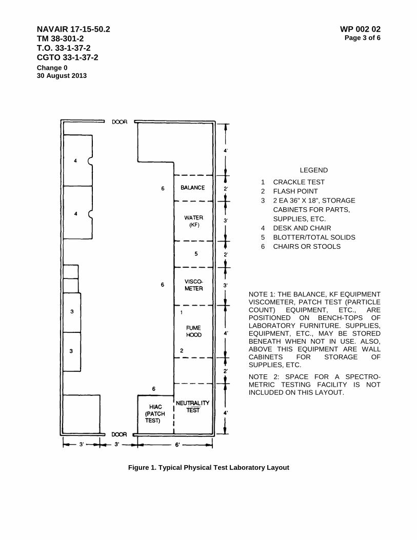
NAVAIR 17-15-50.2 TM 38-301-2 T.O. 33-1-37-2 CGTO 33-1-37-2
WP 002 02 Page 3 of 6
Change 0 30 August 2013
LEGEND
1 CRACKLE TEST 2 FLASH POINT 3 2 EA 36" X 18", STORAGE CABINETS FOR PARTS, SUPPLIES, ETC. 4 DESK AND CHAIR 5 BLOTTER/TOTAL SOLIDS 6 CHAIRS OR STOOLS
NOTE 1: THE BALANCE, KF EQUIPMENT VISCOMETER, PATCH TEST (PARTICLE COUNT) EQUIPMENT, ETC., ARE POSITIONED ON BENCH-TOPS OF LABORATORY FURNITURE. SUPPLIES, EQUIPMENT, ETC., MAY BE STORED BENEATH WHEN NOT IN USE. ALSO, ABOVE THIS EQUIPMENT ARE WALL CABINETS FOR STORAGE OF SUPPLIES, ETC.
NOTE 2: SPACE FOR A SPECTRO-METRIC TESTING FACILITY IS NOT INCLUDED ON THIS LAYOUT.
Figure 1. Typical Physical Test Laboratory Layout

NAVAIR 17-15-50.2 TM 38-301-2 T.O. 33-1-37-2 CGTO 33-1-37-2
WP 002 02 Page 4 of 6
Change 0 30 August 2013
NONAERONAUTICAL EQUIPMENT LUBRICANT SAMPLE ANALYSIS REQUIREMENT GUIDE*
I. ENGINES A. Spectrometric 1. Pass - Go to I.B. 2. Fail - See wear-metal guidelines for specific equipment. a.Critical - Resample to verify.
(1) Wear Metals - abnormal or high range. (2) Oil contamination by dirt or dust - Si increase.
b.Noncritical - Resample to verify, then change oil. (1) Oil contamination by dirt or dust - Si increase. (2) Additive depletion - Zn, Mg, or Cu decrease.
(3) Coolant Problem - B or Na increase by 20 PPM or more. B. Viscosity 1. Pass - Go to I.C. 2. Fail - See viscosity guidelines.
a. Low - Fuel dilution or wrong oil. Verify by flash point test and change oil. If repeat problem, make maintenance recommendation for fuel dilution.
b. High - Soot, sludge, water or wrong oil. Verify by blotter and water tests and change oil.
C. Karl Fischer Test for Water 1. Pass
2. Fail – Refer to Volume II WP 009 00 for the Aquatest 2010 test method.
D. Fourier Transform Infrared (FT-IR) Spectrometric Analysis Results 1. Pass
2. Fail - See FT-IR method number guidelines and analysis readings. Refer to Volume II WP 014 00. a.Free water - Change oil and service filters.
b. Contaminated oil - Soot, Oxidation, Glycol, and Fuel Readings exceed established guidelines, recommend oil changes or inspect and initiate repairs of faulty systems.
Figure 2. Nonaeronautical Equipment Lubricant Sample Analysis Requirement Guide (Sheet 1 of 2)

NAVAIR 17-15-50.2 TM 38-301-2 T.O. 33-1-37-2 CGTO 33-1-37-2
WP 002 02 Page 5 of 6
Change 0 30 August 2013 II. TRANSMISSIONS A. Spectrometric 1. Pass - Go to II.B. 2. Fall - See wear-metal guidelines for specific equipment. a.Critical - Resample to verify.
(1) Wear Metals - abnormal to high range. (2) Oil contamination by dirt or dust - Si Increase. b. Noncritical - Resample to verify, then change oil. (1) Oil contamination by dirt or dust - SI Increase.
(2) Additive depletion - Zn, Mg, or Cu decrease. (3) Water or moisture condensation - Na increase.
B. Viscosity 1. Pass - Go to II.C. 2. Fail - See viscosity guidelines. a. Low - Wrong oil, change oil.
b. High - Sludge, water or wrong oil. Verify by water test and change oil. C. Water test - Karl Fischer 1. Pass 2. Fail – Refer to Volume II WP 009 00 for the Aquatest 2010 test method. D. Fourier Transform Infrared (FT-IR) Spectrometric Analysis Results 1. Pass 2. Fail - See FT-IR method number guidelines and component analysis warnings. Refer to Volume II WP
014 for the FT-IR test method a. Submitting unit to correct the faulty system initiate Critical - Recommend corrective
maintenance actions. b. Non-critical - Change oil and service filter.
(1) Oil contamination by dirt or dust. (2) Additive depletion.
(3) Water or moisture condensation - Sodium (Na) increase.
Ill. HYDRAULIC SYSTEMS The following tests are approved methods of testing hydraulic fluid condition and may be directed by services as required. These tests may be performed singly or in combination as required. (Army laboratories shall use spectrometric, viscosity and water testing as a minimum.)
A. Spectrometric B. Viscosity
C. Water testing, Karl Fischer Method D. Electronic Particulate Count
E. Colorimetric Patch Testing F. Fourier Transform Infrared (FT-IR) Spectrometric analysis (Volume II WP 014 00) for additive depletion
and lubrication degradation contaminants in the components servicing the oil system. 1. Pass
2. Fail - See prescribed guidelines for specific components. a. Water: Change oil and service or replace component filters.
*Sequence of test provided as a guide, not as mandatory requirements.
Figure 2. Nonaeronautical Equipment Lubricant Sample Analysis Requirement Guide (Sheet 2 of 2)

NAVAIR 17-15-50.2 TM 38-301-2 T.O. 33-1-37-2 CGTO 33-1-37-2
WP 002 02 Page 6 of 6
Change 0 30 August 2013
This Page Intentionally Left Blank

NAVAIR 17-15-50.2 TM 38-301-2 T.O. 33-1-37-2 CGTO 33-1-37-2
WP 002 03 Page 1 of 16
Change 0 30 August 2013
ARMY OIL ANALYSIS PROGRAM DATA RECORDING, PROCESSING, AND WAREHOUSING
Table of Contents
Page
1. Introduction ........................................................................................................................................................ 1 2. OASIS Database Structure Summary ............................................................................................................... 1 3. U.S. Army Oil Analysis Reports ......................................................................................................................... 3 a. (Monthly) Resample and Type Recommendation Report ............................................................................ 3 b. (Monthly) Activity Report ............................................................................................................................... 3 c. (Monthly) End Item Configuration Report ..................................................................................................... 4 d. (Monthly) Summary by Equipment Type Report .......................................................................................... 4 e. (Monthly) components Enrolled Report ........................................................................................................ 4 f. Laboratory Workload Summary Report ........................................................................................................ 4 g. (On request) Laboratory Response Time Report ......................................................................................... 5 h. (Monthly) Usage and Sample Status Report ................................................................................................ 5
1. INTRODUCTION. The Oil Analysis Standard Interservice System (OASIS) is the primary software program used by Army Oil Analysis Program Laboratories to collect, process and warehouse oil analysis data. The AOAP Program Manager will provide technical assistance and initiate corrective software program changes to OASIS as necessary. If OASIS software support is required, contact the AOAP Manager as follows:
ARMY OIL ANALYSIS PROGRAM OFFICE USAMC LOGISTICS SUPPORT ACTIVITY ATTN AMXLS-GO BUILDING 3661 REDSTONE ARSENAL AL 35898-7466 AOAP Hot Line DSN: 645-0869 / (256) 955-0869 Data Facsimile: 746-9344 / (256) 876-9344 DDN address: [email protected]
2. OASIS DATABASE STRUCTURE SUMMARY
a. Structure for Database: TAPEFILE.DBF
Fld Fld Name Type Width Dec Start End
1 TRANSCODE C 1 1 1
Code for Transaction being recorded I - Initial Record for this Sample C - Change Record for Sample D - Sample Deleted Record F - Feedback Record U - Undelete Sample Record
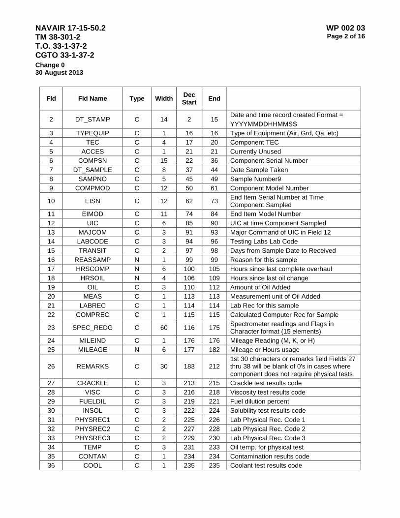
NAVAIR 17-15-50.2 TM 38-301-2 T.O. 33-1-37-2 CGTO 33-1-37-2
WP 002 03 Page 2 of 16
Change 0 30 August 2013
Fld Fld Name Type Width Dec Start End
2 DT_STAMP C 14 2 15 Date and time record created Format = YYYYMMDDHHMMSS
3 TYPEQUIP C 1 16 16 Type of Equipment (Air, Grd, Qa, etc) 4 TEC C 4 17 20 Component TEC 5 ACCES C 1 21 21 Currently Unused 6 COMPSN C 15 22 36 Component Serial Number 7 DT_SAMPLE C 8 37 44 Date Sample Taken 8 SAMPNO C 5 45 49 Sample Number9 9 COMPMOD C 12 50 61 Component Model Number
10 EISN C 12 62 73 End Item Serial Number at Time Component Sampled
11 EIMOD C 11 74 84 End Item Model Number 12 UIC C 6 85 90 UIC at time Component Sampled 13 MAJCOM C 3 91 93 Major Command of UIC in Field 12 14 LABCODE C 3 94 96 Testing Labs Lab Code 15 TRANSIT C 2 97 98 Days from Sample Date to Received 16 REASSAMP N 1 99 99 Reason for this sample 17 HRSCOMP N 6 100 105 Hours since last complete overhaul 18 HRSOIL N 4 106 109 Hours since last oil change 19 OIL C 3 110 112 Amount of Oil Added 20 MEAS C 1 113 113 Measurement unit of Oil Added 21 LABREC C 1 114 114 Lab Rec for this sample 22 COMPREC C 1 115 115 Calculated Computer Rec for Sample
23 SPEC_REDG C 60 116 175 Spectrometer readings and Flags in Character format (15 elements)
24 MILEIND C 1 176 176 Mileage Reading (M, K, or H) 25 MILEAGE N 6 177 182 Mileage or Hours usage
26 REMARKS C 30 183 212 1st 30 characters or remarks field Fields 27 thru 38 will be blank of 0's in cases where component does not require physical tests
27 CRACKLE C 3 213 215 Crackle test results code 28 VISC C 3 216 218 Viscosity test results code 29 FUELDIL C 3 219 221 Fuel dilution percent 30 INSOL C 3 222 224 Solubility test results code 31 PHYSREC1 C 2 225 226 Lab Physical Rec. Code 1 32 PHYSREC2 C 2 227 228 Lab Physical Rec. Code 2 33 PHYSREC3 C 2 229 230 Lab Physical Rec. Code 3 34 TEMP C 3 231 233 Oil temp. for physical test 35 CONTAM C 1 234 234 Contamination results code 36 COOL C 1 235 235 Coolant test results code
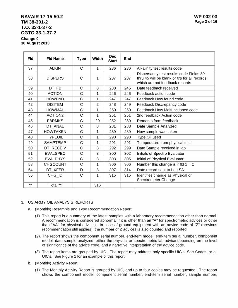
NAVAIR 17-15-50.2 TM 38-301-2 T.O. 33-1-37-2 CGTO 33-1-37-2
WP 002 03 Page 3 of 16
Change 0 30 August 2013
Fld Fld Name Type Width Dec Start End
37 ALKIN C 1 236 236 Alkalinity test results code
38 DISPERS C 1 237 237 Dispersancy test results code Fields 39 thru 45 will be blank or 0's for all records which are not feedback records
39 DT_FB C 8 238 245 Date feedback received 40 ACTION C 1 246 246 Feedback action code 41 HOWFND C 1 247 247 Feedback How found code 42 DISITEM C 2 248 249 Feedback Discrepancy code 43 HOWMAL C 1 250 250 Feedback How Malfunctioned code 44 ACTION2 C 1 251 251 2nd feedback Action code 45 FBRMKS C 29 252 280 Remarks from feedback 46 DT_ANAL C 8 281 288 Date Sample Analyzed 47 HOWTAKEN C 1 289 289 How sample was taken 48 TYPEOIL C 1 290 290 Type Oil used 49 SAMPTEMP C 1 291 291 Temperature from physical test 50 DT_RECEIV C 8 292 299 Date Sample received in lab 51 EVALSPEC C 3 300 302 Initials of Spectro Evaluator 52 EVALPHYS C 3 303 305 Initial of Physical Evaluator 53 CHGCOUNT C 1 306 306 Number this change is if fld 1 = C 54 DT_XFER D 8 307 314 Date record sent to Log SA 55 CHG_ID C 1 315 315 Identifies change as Physical or
Spectrometer Change ** Total ** 316
3. US ARMY OIL ANALYSIS REPORTS
a. (Monthly) Resample and Type Recommendation Report.
(1). This report is a summary of the latest samples with a laboratory recommendation other than normal. A recommendation is considered abnormal if it is other than an "A" for spectrometric advices or other than "AA" for physical advices. In case of ground equipment with an advice code of "Z" (previous recommendation still applies), the number of Z advices is also counted and reported.
(2). The report shows the component serial number, end-item model, end-item serial number, component model, date sample analyzed, either the physical or spectrometric lab advice depending on the level of significance of the advice code, and a narrative interpretation of the advice code.
(3). The report items are grouped by UIC. The report may address only specific UIC's, Sort Codes, or all UIC's. See Figure 1 for an example of this report.
b. (Monthly) Activity Report.
(1). The Monthly Activity Report is grouped by UIC, and up to four copies may be requested. The report shows the component model, component serial number, end-item serial number, sample number,
NAVAIR 17-15-50.2 TM 38-301-2 T.O. 33-1-37-2 CGTO 33-1-37-2
WP 002 03 Page 4 of 16
Change 0 30 August 2013
date sample analyzed, days in transit, hours since overhaul, hours since oil change, reason for sample and either the physical or spectrometric lab advice depending on the level of significance of the advice code.
(2). This information is shown for all samples for each piece of equipment. The report also includes totals for number of samples analyzed for the month, the average days in transit, and the number of samples processed with 'UNKNOWN" HSOH (hours since overhaul) and HSOC (hours since oil change). See Figure 2 for an example of this report.
c. (Monthly) End Item Configuration Report. The End Item Configuration Report shows the end-item model, end-item serial number, UIC, component model, component serial number, and dates of the last five samples taken. This report is sorted by end-item serial number, component model, and component serial number. See Figure 3 for an example of this report.
d. (Monthly) Summary by Equipment Type Report. The Summary by Equipment Type Report is a summary of laboratory recommendations given for samples processed for the previous month. See Figure 4 for an example of this report.
e. (Monthly) Components Enrolled Report.
(1). The Components Enrolled Report lists the history records that contain a sample processed in the lab during the reporting period. The report includes all components enrolled through the last day of the previous month.
(2). The top of the report shows the sort code, UIC, unit name and address, report date, and name of the laboratory.
(3). For ground equipment, the body of the reports shows bumper number, end-item model, end-item serial number, component model, component serial number, hours since overhaul, hours since oil change, sampling interval hours/days, date sample taken, reason sampled, and remarks. If the equipment is TDY, the word TDY will appear in the remarks column.
(4). The report is sorted by sort code, UIC, end-item serial number, TEC, and the component serial number and bumper number for ground equipment. See Figures 5 and 6 for an example of this report.
f. Laboratory Workload Summary Report.
(1). The Laboratory Workload Summary report is sorted by sort code, UIC, end-item serial number, component TEC, and component serial number. The report shows a breakdown of lab recommendations, reasons for sample, and feedback required for samples within a UIC. The report is a summary of samples analyzed during the previous month.
(2). The "unit summary" part of the report shows the number of end-items enrolled, the number of components enrolled, and the number of feedback required within a UIC. In addition for ground equipment, the report shows the percentage of components that have no usage reported and the percentage of components that are delinquent. Delinquency occurs when an enrolled component is not sampled during the established sampling interval.
(3). The "type sample" part of the reports shows a breakdown of the reason for sample codes given to the samples. Any samples with the reason "R" are classified as routine; any with an "L" are classified as lab requests, and all others are classified as "other".
(4). The "lab recommendation" part of the report shows either the physical or spectrometric lab advice depending on the level of significance in the advice code file for the samples. The advices are grouped as normal, resample, purify oil, and inspect. See Figures 7 and 8 for an example of this report.

NAVAIR 17-15-50.2 TM 38-301-2 T.O. 33-1-37-2 CGTO 33-1-37-2
WP 002 03 Page 5 of 16
Change 0 30 August 2013
g. (On Request) Laboratory Response Time Report.
(1). This report is automatically produced when the laboratory workload summary is selected. The Laboratory Response Time Report reflects the number of days between receiving and processing a sample. The report is a summary of the number of samples processed within 0-10 days, over 10 days, unknown days, total samples processed, and the average response time in days.
(2). The grand totals produced by the report are saved in a disk file for transmission of FSA (PROV). See Figure 9 for an example of the report.
h. (Monthly) Usage and Sample Status Report.
(1). The end-item usage and component status report is produced on a monthly basis by UIC for ground equipment only.
(2). The report shows the bumper number, component model, end-item model, end-item serial number, end-item meter reading, component serial number, sample number, date sample taken, date sample next due, days delinquent, feedback required, sample number, date, and remarks. Totals are provided end-items enrolled, components enrolled, end-items with no usage, recommendations with no feedback, components delinquent, and percentage of end-items with no usage. See Figure 10 for an example of this report.

NAVAIR 17-15-50.2 TM 38-301-2 T.O. 33-1-37-2 CGTO 33-1-37-2
WP 002 03 Page 6 of 16
Change 0 30 August 2013
Figure 1 - (Monthly) Resample and Type Recommendation Report
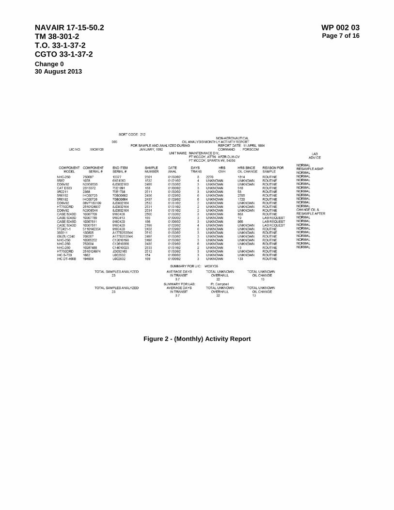
NAVAIR 17-15-50.2 TM 38-301-2 T.O. 33-1-37-2 CGTO 33-1-37-2
WP 002 03 Page 7 of 16
Change 0 30 August 2013
Figure 2 - (Monthly) Activity Report
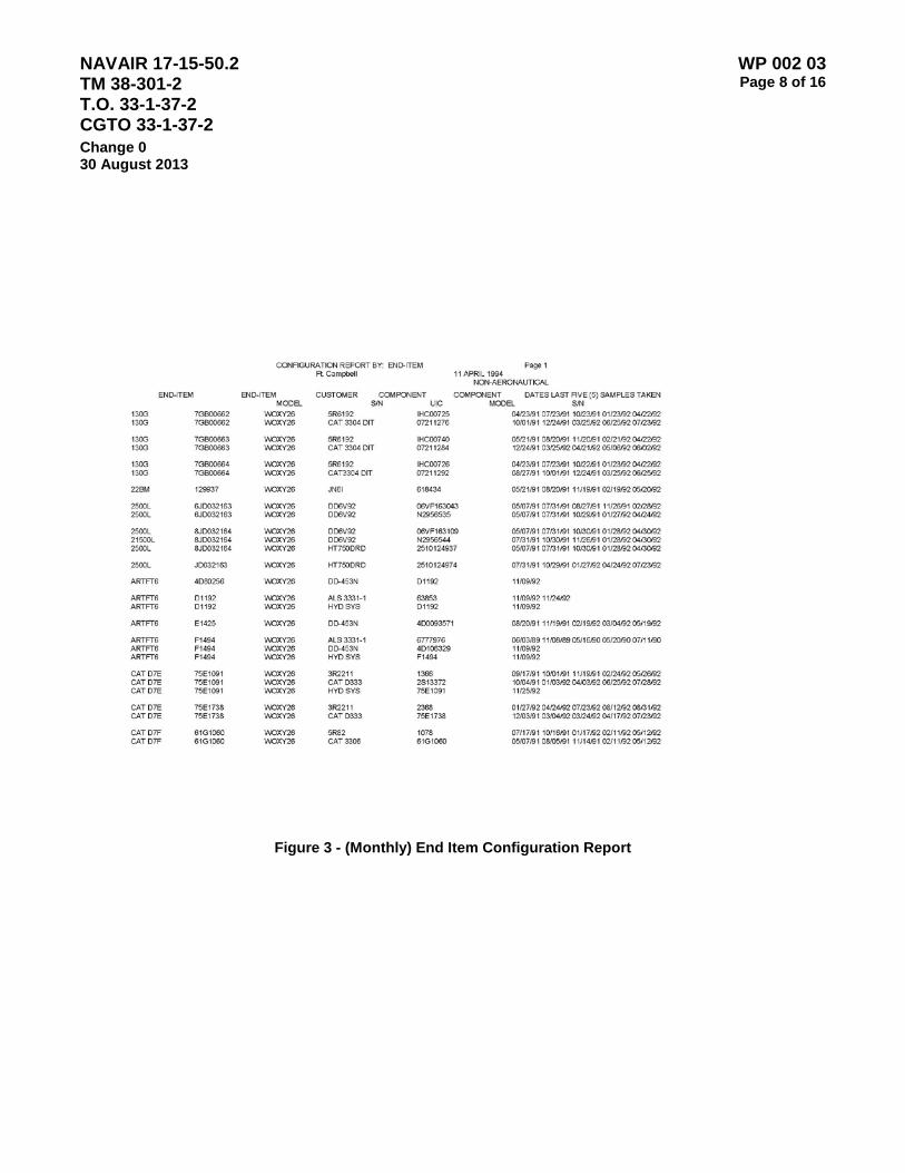
NAVAIR 17-15-50.2 TM 38-301-2 T.O. 33-1-37-2 CGTO 33-1-37-2
WP 002 03 Page 8 of 16
Change 0 30 August 2013
Figure 3 - (Monthly) End Item Configuration Report

NAVAIR 17-15-50.2 TM 38-301-2 T.O. 33-1-37-2 CGTO 33-1-37-2
WP 002 03 Page 9 of 16
Change 0 30 August 2013
Figure 4 - (Monthly) Summary Equipment Type Report
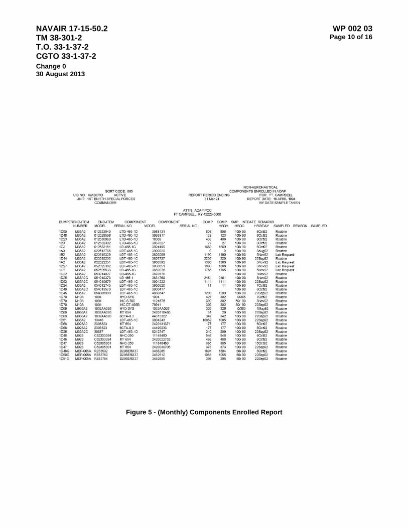
NAVAIR 17-15-50.2 TM 38-301-2 T.O. 33-1-37-2 CGTO 33-1-37-2
WP 002 03 Page 10 of 16
Change 0 30 August 2013
Figure 5 - (Monthly) Components Enrolled Report
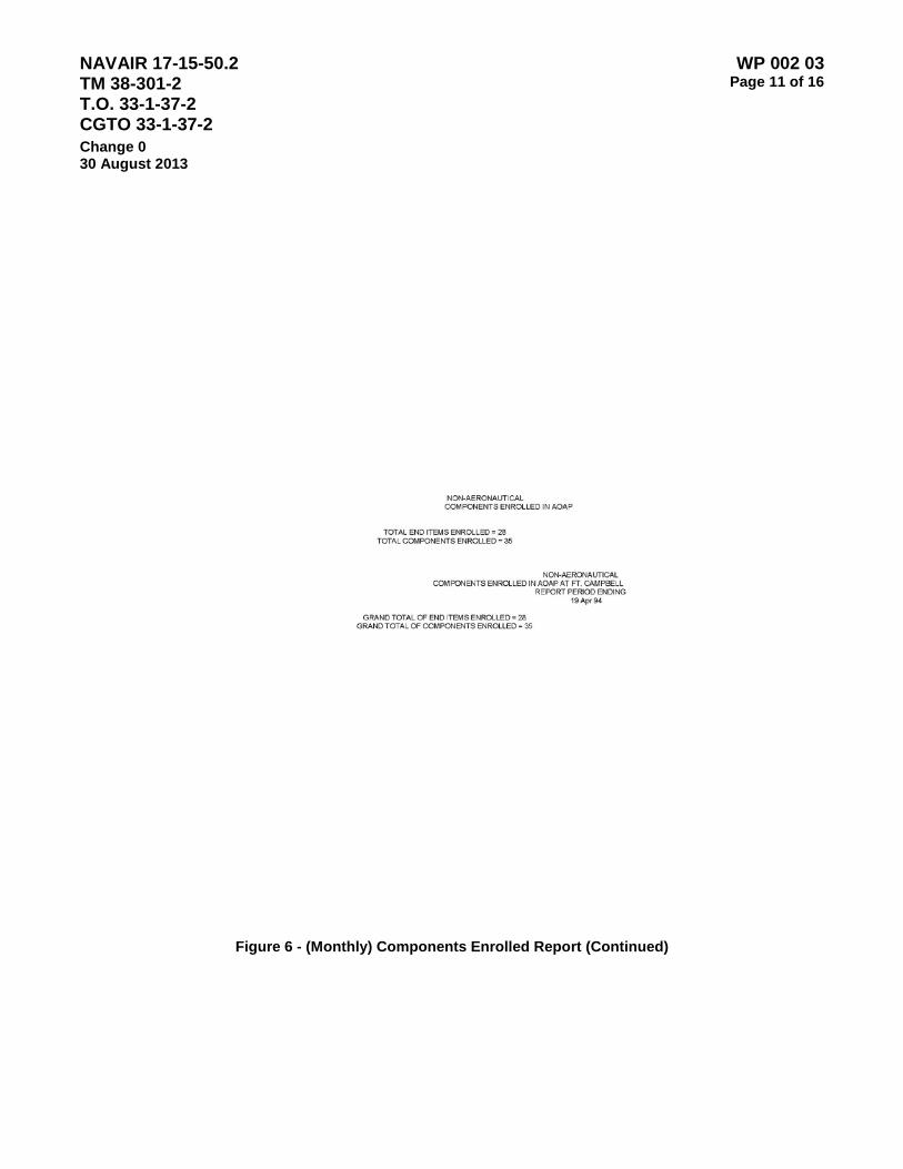
NAVAIR 17-15-50.2 TM 38-301-2 T.O. 33-1-37-2 CGTO 33-1-37-2
WP 002 03 Page 11 of 16
Change 0 30 August 2013
Figure 6 - (Monthly) Components Enrolled Report (Continued)
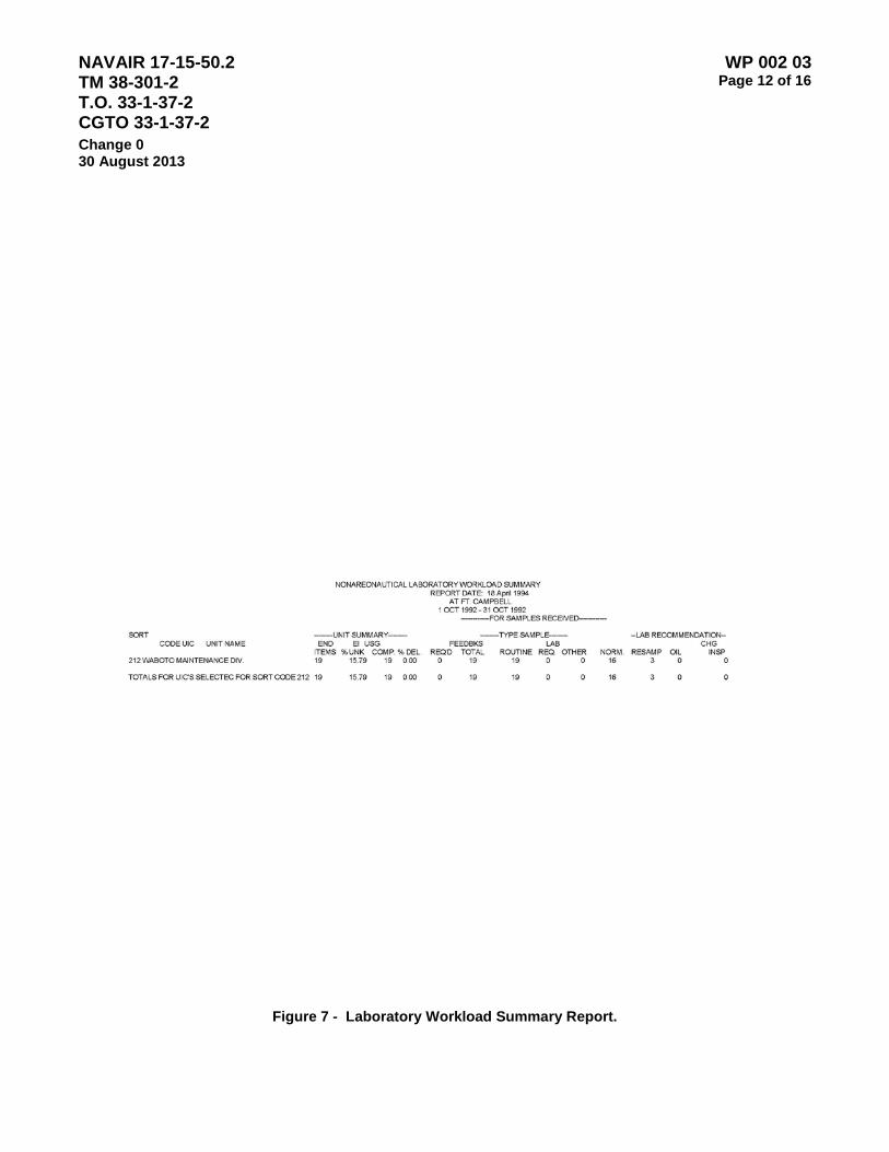
NAVAIR 17-15-50.2 TM 38-301-2 T.O. 33-1-37-2 CGTO 33-1-37-2
WP 002 03 Page 12 of 16
Change 0 30 August 2013
Figure 7 - Laboratory Workload Summary Report.

NAVAIR 17-15-50.2 TM 38-301-2 T.O. 33-1-37-2 CGTO 33-1-37-2
WP 002 03 Page 13 of 16
Change 0 30 August 2013
Figure 8 - Laboratory Workload Summary Report (Continued).

NAVAIR 17-15-50.2 TM 38-301-2 T.O. 33-1-37-2 CGTO 33-1-37-2
WP 002 03 Page 14 of 16
Change 0 30 August 2013
Figure 9 - (On Request) Laboratory Response Time Report

NAVAIR 17-15-50.2 TM 38-301-2 T.O. 33-1-37-2 CGTO 33-1-37-2
WP 002 03 Page 15 of 16
Change 0 30 August 2013
Figure 10 - (Monthly) Usage and Sample Status Report

NAVAIR 17-15-50.2 TM 38-301-2 T.O. 33-1-37-2 CGTO 33-1-37-2
WP 002 03 Page 16 of 16
Change 0 30 August 2013
This Page Intentionally Left Blank

NAVAIR 17-15-50.2 TM 38-301-2 T.O. 33-1-37-2 CGTO 33-1-37-2
WP 03 00 Page 1 of 2
Change 0 30 August 2013
NAVY OIL ANALYSIS PROGRAM LABORATORIES OPERATING REQUIREMENTS AND PROCEDURES
1. Purpose. The purpose of this work package is to establish the specific configuration requirements and operating procedures for Navy Oil Analysis Program Laboratories.
2. Applicability. The provisions of this work package apply to all Navy Oil Analysis Program Laboratories.
3. Work Package Structure. This Work Package is divided into three sections (subordinate work packages):
WP 03 01 – General Laboratory Operating Requirements and Procedures.
WP 03 02 – Laboratory Equipment / Configuration Requirements
WP 03 03 – Lubricant Analysis and Research Application (LARA) Software Operations Guide

NAVAIR 17-15-50.2 TM 38-301-2 T.O. 33-1-37-2 CGTO 33-1-37-2
WP 03 00 Page 2 of 2
Change 0 30 August 2013
This Page Intentionally Left Blank
NAVAIR 17-15-50.2 TM 38-301-2 T.O. 33-1-37-2 CGTO 33-1-37-2
WP 003 01 Page 1 of 8
Change 0 30 August 2013
NAVY OIL ANALYSIS PROGRAM - GENERAL LABORATORY OPERATING PROCEDURES
Table of Contents
Page
1. Lab Operator Training and Certification ........................................................................................................... 1 2. Lab Operator SharePoint Registration ............................................................................................................. 2 3. NOAP Lab Email Account ................................................................................................................................ 2 4. Sample Processing and Turnaround Requirements ........................................................................................ 2 5. Evaluation of Sample Results........................................................................................................................... 2 6. Reports ............................................................................................................................................................. 2 7. Participation in the JOAP Spectrometer Correlation Program ......................................................................... 3 8. Laboratory Logs ................................................................................................................................................ 3 9. Data submission to master database on SharePoint ....................................................................................... 3 10. Laboratory Supplies .......................................................................................................................................... 3 11. Spectrometer Maintenance and Inspections .................................................................................................... 3
1. Lab Operator Training and Certification.
a. All NOAP Laboratory Operators must be trained by taking Defense Joint Oil Analysis Program (Physical Properties Testing) Course Identification Number (CIN) A-491-0017A, and obtaining certification to Navy Enlisted Classification AD-6403. For information on the course, review course information, quota control, seat availability and POC in the Catalog of Navy Training Courses (CANTRAC) at http://www.netc.navy.mil/Development.aspx. (Requires CAC log in). The telephone number for student registration is 850-452-7200 ext 4184. The entire course curriculum must be taken and is not available in other formats. The NOAP Program Manager can certify civilian lab operators based on their completion of commercially available training courses. On the job (OJT) refresher training under the guidance of a NOAP Lab Technician is highly recommended for lab operators who are re-engaging in NOAP Lab testing operations after a hiatus of a year or more. Contact the NOAP Program Team Lead by sending an email to [email protected] for more information about OJT.
b. Marine Certification Requirements And Laboratory Evaluator Responsibilities. Marine personnel paygrade E4-E7 certification IAW this appendix:
1. Marine Lab Operators must be pay-grade E4 or above and must complete Joint Oil Analysis Program (JOAP) Course Identification Number (CIN) A-491-0017. This is a non-MOS awarding course.
2. Marine Lab Operators must be a certified Navy Oil Analysis Program (NOAP) E5 or above to evaluate, certify and report analytical test data to the customer (not the Q/A NOAP Program Manager due to conflict of interest).
NOTE
Certified Marine paygrade E4 personnel are not authorized to perform any laboratory duties unless under the direct supervision of a certified E5 NOAP Laboratory Technician, and can only be utilized as an operator of all associated NOAP equipment to perform multi-fluid analysis.

NAVAIR 17-15-50.2 TM 38-301-2 T.O. 33-1-37-2 CGTO 33-1-37-2
WP 003 01 Page 2 of 8
Change 0 30 August 2013 2. Lab Operator SharePoint Registration. Laboratory Operators must register with the Navy Oil Analysis
Program Team Lead for access to the NOAP Laboratory Operators’ WorkSpace website on myNAVAIR. To register send an email to [email protected] providing your name and the NOAP Lab to which you have been assigned. Lab Operators must also report changes in duty station (including reassignment to a different NOAP Laboratory), email address or phone number(s) by sending an email to [email protected].
The NOAP Laboratory Operators’ WorkSpace website is the primary repository for NOAP data and information and is used by both laboratory operators and customers. The URL for the NOAP Laboratory Operators’ WorkSpace website:
https://myteam.navair.navy.mil/air/44/nflcft/NOAP/NOAPLABS/SitePages/Home.aspx
3. NOAP Lab Email Account. Each lab must establish a unique email account with their email service provider, some examples: [email protected]; [email protected]. The NOAP Team Lead will issue instructions and information to these accounts. All lab operators are required to verify receipt of messages in this account inbox by sending a reply to [email protected].
4. Sample Processing and Turnaround Requirements. Laboratory Operators are required to test all samples received for which they have the proper test equipment (See WP 003 02) regardless of the sample’s source. Lab Operators are required to report results from received samples (report results) back to the submitting activity via email, Naval Message or regular mail as follows:
a. Routine Aeronautical Samples: Test the samples within 24 clock hours of receipt of sample(s) and provide the LARA History Listing report to the activity which submitted the sample within one week (See paragraph 6 on reporting requirements below). Weekends and holidays are excluded.
b. Routine Non-aeronautical Samples: Test within 72 clock hours of receipt of sample(s) and provide LARA History Listing report to the activity which submitted the sample within one week (See paragraph 6 on reporting requirements below). Weekends and holidays are excluded.
c. Special Samples: Test within 24 hours of receipt of sample(s) and provide the submitting activity with a copy of the report immediately.
NOTE:
Abnormal results which necessitate advising the submitting activity to take action, i.e. change oil, re-sample, ground aircraft, etc. must be sent immediately via email or Naval Message.
5. Evaluation of Sample Results. The Laboratory Operator will evaluate each sample’s test results in accordance with the applicable work package in Volume III or Volume IV of this manual.
6. Reports. Reports are generated by the Lubricant Analysis and Research Application (LARA) software program. See Work Package WP 003 03 for specific instructions on preparing and distributing reports. The following reports shall be produced once a week:
a. Equipment Sample Log. This report shall be used to list the UICs and CSNs served by the lab for the current month. The date range is specified by the two "Dates Between" dropdown options. As a minimum these dates should cover the preceding week (7 days) however two weeks are recommended to avoid missing data.
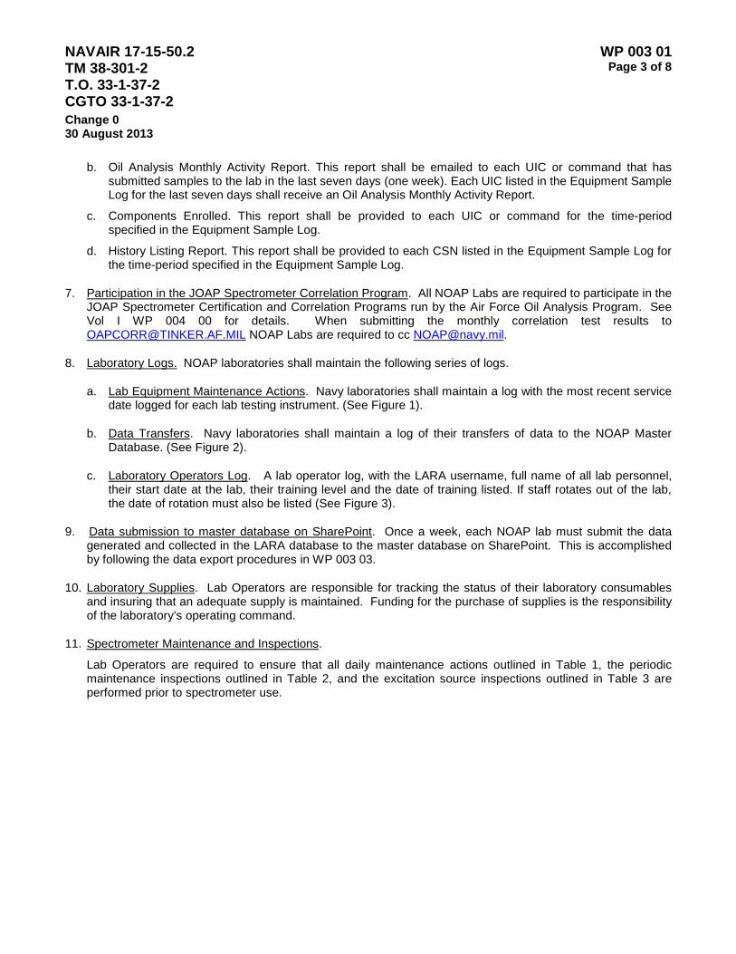
NAVAIR 17-15-50.2 TM 38-301-2 T.O. 33-1-37-2 CGTO 33-1-37-2
WP 003 01 Page 3 of 8
Change 0 30 August 2013
b. Oil Analysis Monthly Activity Report. This report shall be emailed to each UIC or command that has submitted samples to the lab in the last seven days (one week). Each UIC listed in the Equipment Sample Log for the last seven days shall receive an Oil Analysis Monthly Activity Report.
c. Components Enrolled. This report shall be provided to each UIC or command for the time-period specified in the Equipment Sample Log.
d. History Listing Report. This report shall be provided to each CSN listed in the Equipment Sample Log for the time-period specified in the Equipment Sample Log.
7. Participation in the JOAP Spectrometer Correlation Program. All NOAP Labs are required to participate in the JOAP Spectrometer Certification and Correlation Programs run by the Air Force Oil Analysis Program. See Vol I WP 004 00 for details. When submitting the monthly correlation test results to [email protected] NOAP Labs are required to cc [email protected].
8. Laboratory Logs. NOAP laboratories shall maintain the following series of logs.
a. Lab Equipment Maintenance Actions. Navy laboratories shall maintain a log with the most recent service date logged for each lab testing instrument. (See Figure 1).
b. Data Transfers. Navy laboratories shall maintain a log of their transfers of data to the NOAP Master Database. (See Figure 2).
c. Laboratory Operators Log. A lab operator log, with the LARA username, full name of all lab personnel, their start date at the lab, their training level and the date of training listed. If staff rotates out of the lab, the date of rotation must also be listed (See Figure 3).
9. Data submission to master database on SharePoint. Once a week, each NOAP lab must submit the data generated and collected in the LARA database to the master database on SharePoint. This is accomplished by following the data export procedures in WP 003 03.
10. Laboratory Supplies. Lab Operators are responsible for tracking the status of their laboratory consumables and insuring that an adequate supply is maintained. Funding for the purchase of supplies is the responsibility of the laboratory’s operating command.
11. Spectrometer Maintenance and Inspections.
Lab Operators are required to ensure that all daily maintenance actions outlined in Table 1, the periodic maintenance inspections outlined in Table 2, and the excitation source inspections outlined in Table 3 are performed prior to spectrometer use.

NAVAIR 17-15-50.2 TM 38-301-2 T.O. 33-1-37-2 CGTO 33-1-37-2
WP 003 01 Page 4 of 8
Change 0 30 August 2013
Table 1 – Spectrometer Daily Maintenance
Component Required Maintenance Frequency Maintenance Level
Plate, Mounting, Sample Stand Component
Clean to remove oil and carbon buildup especially between disc electrode shaft and rod electrode holder.
Every 5 burns Operator
Window, Quartz, Protec tive
Clean to remove oil and carbon splashes with isopropyl alcohol or an ammonia based window cleaner.
Every 5 burns Operator
Sensors, Sample Stand Using a Q-tip, clean to remove oil and carbon splashes with an isopropyl alcohol or ammonia based window cleaner.
Daily Operator
Sample Stand Area Clean complete sample chamber to remove oil splashes and carbon buildup. Twice Daily Operator
Door, Sample Stand Clean complete door to remove oil splashes and carbon buildup. Twice Daily Operator
Electrode Sharpener Rotate cutting blade to new edge. (Can be performed until all three edges have been used.)
As Required Operator
Panel, Readout and Control
Inspect for oil splashes and carbon residue. If present, remove with mild cleaning detergent. Daily Operator
Frame and Exterior Panels
Inspect for oil splashes and dust buildup. If present, remove with mild detergent. CAUTION: DO NOT USE ALCO- HOL OR CHLORINATED SOL- VENTS TO CLEAN PLASTIC OR PAINTED SURFACES.
Daily Operator
Printer
Inspect for worn ribbon, loose cable connectors, and dirt and dust build- up. Replace worn ribbon, tighten loose connections and clean accord-ingly. Refer to printer operation and maintenance manual.
Daily Operator

NAVAIR 17-15-50.2 TM 38-301-2 T.O. 33-1-37-2 CGTO 33-1-37-2
WP 003 01 Page 5 of 8
Change 0 30 August 2013
Table 2 – Spectrometer External Housing Maintenance Inspections
Component Required Maintenance Frequency Maintenance Level
Filter on Heat
Exchanger
Inspect for dust and dirt buildup. Clean in detergent and water bath by swishing vigorously.
Weekly or as required depending on operating
environment. Operator
Filter, Sample Stand
Exhaust Inspect for dust and dirt buildup. Clean or replace if holes in the filter are blocked.
Weekly Operator
Frame and Exterior
Panels Inspect for oil, dust, dents, scratches and rust. Clean with mild detergent and if necessary, sand and repaint.
Monthly Operator
Hardware
Inspect for loose or missing hard- ware. Tighten loose hardware and replace rusted hardware.
Monthly Operator
External Cables Inspect for loose connections.
Inspect for damage. Monthly Operator
Shaft, Disc Electrode Clean residue (varnish) from splined end with an ink eraser. Monthly Operator
Table 3 – Spectrometer Excitation Source Maintenance Inspections
Component Required Maintenance Frequency Maintenance Level
Analytical Gap
Inspect the rod electrode holder and gap setting device for smooth sliding and release. If tight or binding, adjust or remove and replace gap setting device.
Six months or every 2000 burns. Operator
Analytical Gap Polish tips to remove corrosion Six months or every 2000 burns Operator
Analytical Gap
Check electrode shape. If electrode points are flat, remove electrodes and replace them. Reset the auxiliary gap distance to 0.135 inches. Verify by checking excitation source frequency with Source Frequency Test Meter
Six months or every 2000 burns Operator
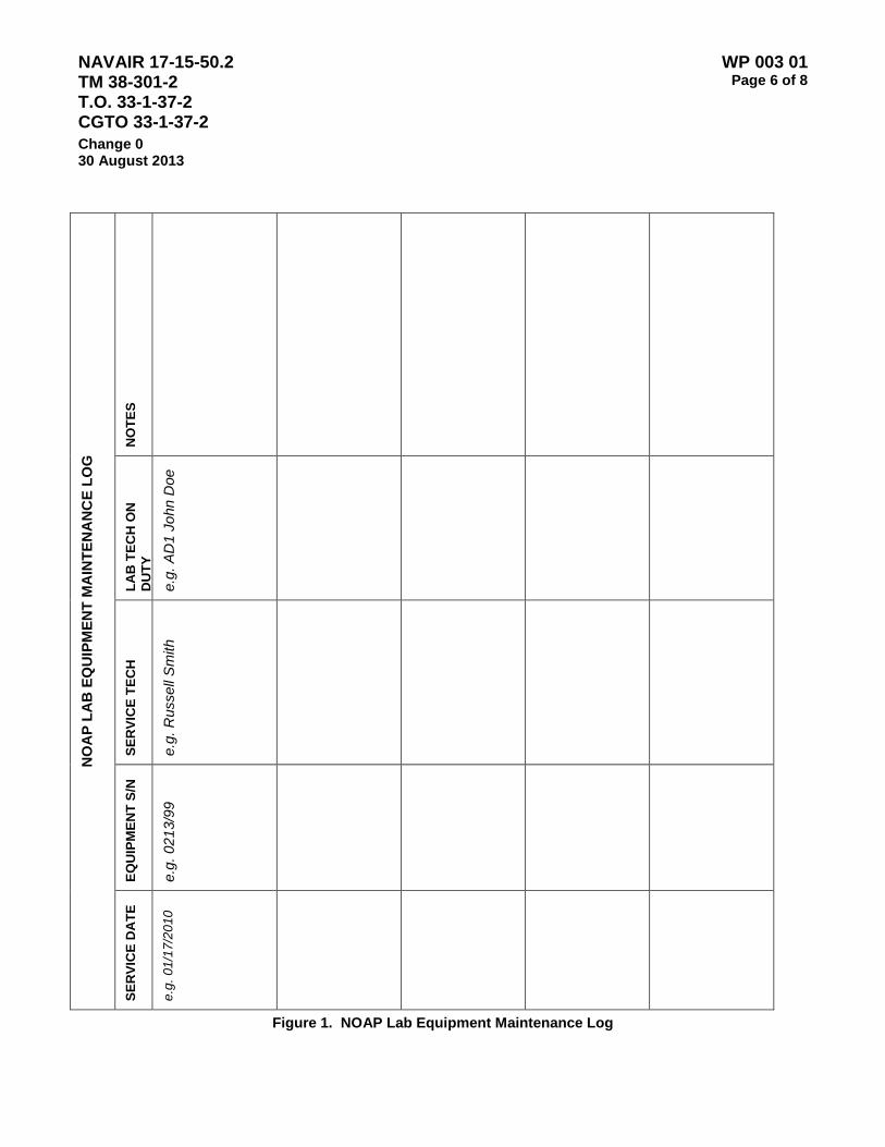
NAVAIR 17-15-50.2 TM 38-301-2 T.O. 33-1-37-2 CGTO 33-1-37-2
WP 003 01 Page 6 of 8
Change 0 30 August 2013
NO
AP
LAB
EQ
UIP
MEN
T M
AIN
TEN
AN
CE
LOG
NO
TES
LAB
TEC
H O
N
DU
TY
e.g.
AD
1 Jo
hn D
oe
SER
VIC
E TE
CH
e.g.
Rus
sell
Sm
ith
EQU
IPM
ENT
S/N
e.g.
021
3/99
SER
VIC
E D
ATE
e.g.
01/
17/2
010
Figure 1. NOAP Lab Equipment Maintenance Log
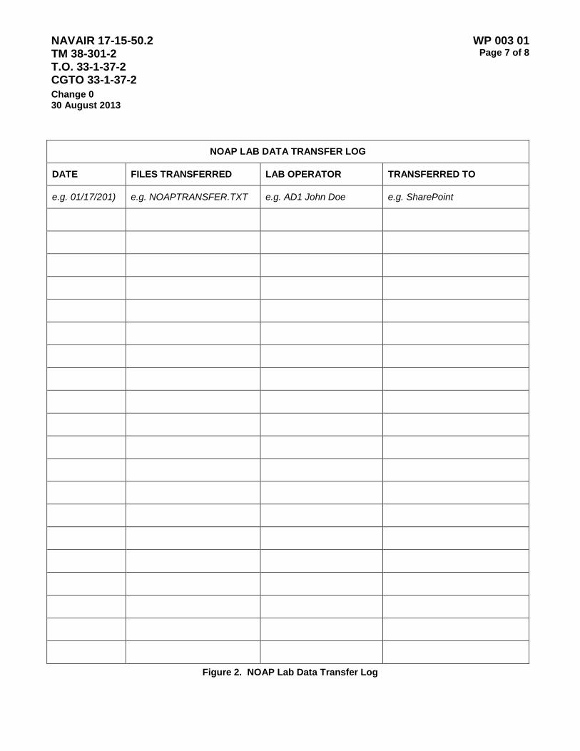
NAVAIR 17-15-50.2 TM 38-301-2 T.O. 33-1-37-2 CGTO 33-1-37-2
WP 003 01 Page 7 of 8
Change 0 30 August 2013
NOAP LAB DATA TRANSFER LOG
DATE FILES TRANSFERRED LAB OPERATOR TRANSFERRED TO
e.g. 01/17/201) e.g. NOAPTRANSFER.TXT e.g. AD1 John Doe e.g. SharePoint
Figure 2. NOAP Lab Data Transfer Log
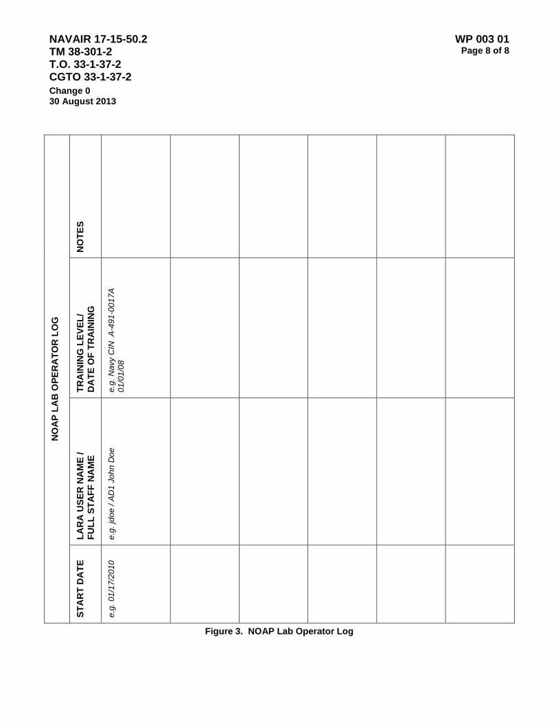
NAVAIR 17-15-50.2 TM 38-301-2 T.O. 33-1-37-2 CGTO 33-1-37-2
WP 003 01 Page 8 of 8
Change 0 30 August 2013
NO
AP
LAB
OPE
RA
TOR
LO
G
NO
TES
TRA
ININ
G L
EVEL
/ D
ATE
OF
TRA
ININ
G
e.g.
Nav
y C
IN A
-491
-001
7A
01/0
1/08
LAR
A U
SER
NA
ME
/ FU
LL S
TAFF
NA
ME
e.g.
jdoe
/ A
D1
John
Doe
STA
RT
DA
TE
e.g.
01/
17/2
010
Figure 3. NOAP Lab Operator Log
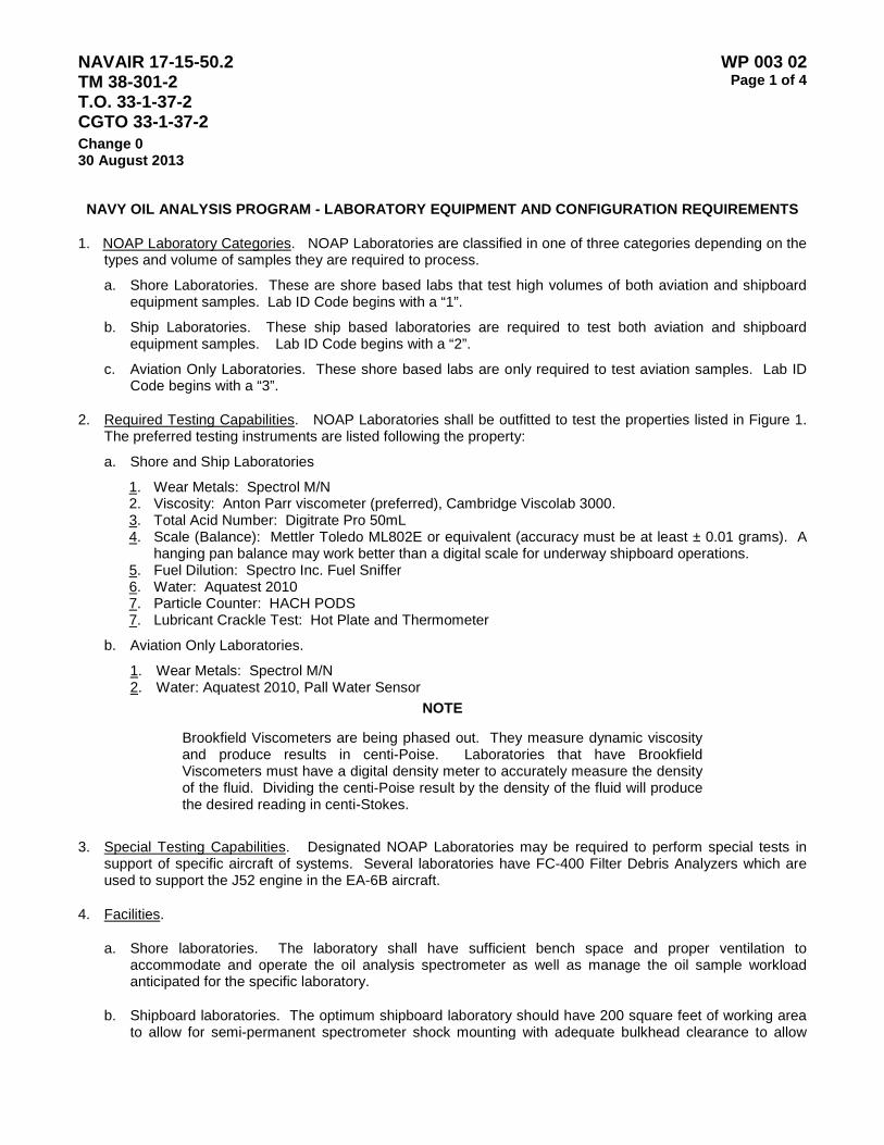
NAVAIR 17-15-50.2 TM 38-301-2 T.O. 33-1-37-2 CGTO 33-1-37-2
WP 003 02 Page 1 of 4
Change 0 30 August 2013
NAVY OIL ANALYSIS PROGRAM - LABORATORY EQUIPMENT AND CONFIGURATION REQUIREMENTS
1. NOAP Laboratory Categories. NOAP Laboratories are classified in one of three categories depending on the types and volume of samples they are required to process.
a. Shore Laboratories. These are shore based labs that test high volumes of both aviation and shipboard equipment samples. Lab ID Code begins with a “1”.
b. Ship Laboratories. These ship based laboratories are required to test both aviation and shipboard equipment samples. Lab ID Code begins with a “2”.
c. Aviation Only Laboratories. These shore based labs are only required to test aviation samples. Lab ID Code begins with a “3”.
2. Required Testing Capabilities. NOAP Laboratories shall be outfitted to test the properties listed in Figure 1. The preferred testing instruments are listed following the property:
a. Shore and Ship Laboratories
1. Wear Metals: Spectrol M/N 2. Viscosity: Anton Parr viscometer (preferred), Cambridge Viscolab 3000. 3. Total Acid Number: Digitrate Pro 50mL 4. Scale (Balance): Mettler Toledo ML802E or equivalent (accuracy must be at least ± 0.01 grams). A
hanging pan balance may work better than a digital scale for underway shipboard operations. 5. Fuel Dilution: Spectro Inc. Fuel Sniffer 6. Water: Aquatest 2010 7. Particle Counter: HACH PODS 7. Lubricant Crackle Test: Hot Plate and Thermometer
b. Aviation Only Laboratories.
1. Wear Metals: Spectrol M/N 2. Water: Aquatest 2010, Pall Water Sensor
NOTE
Brookfield Viscometers are being phased out. They measure dynamic viscosity and produce results in centi-Poise. Laboratories that have Brookfield Viscometers must have a digital density meter to accurately measure the density of the fluid. Dividing the centi-Poise result by the density of the fluid will produce the desired reading in centi-Stokes.
3. Special Testing Capabilities. Designated NOAP Laboratories may be required to perform special tests in support of specific aircraft of systems. Several laboratories have FC-400 Filter Debris Analyzers which are used to support the J52 engine in the EA-6B aircraft.
4. Facilities.
a. Shore laboratories. The laboratory shall have sufficient bench space and proper ventilation to accommodate and operate the oil analysis spectrometer as well as manage the oil sample workload anticipated for the specific laboratory.
b. Shipboard laboratories. The optimum shipboard laboratory should have 200 square feet of working area to allow for semi-permanent spectrometer shock mounting with adequate bulkhead clearance to allow

NAVAIR 17-15-50.2 TM 38-301-2 T.O. 33-1-37-2 CGTO 33-1-37-2
WP 003 02 Page 2 of 4
Change 0 30 August 2013
access to equipment for required maintenance and servicing and to provide adequate space for administrative/records filing and storage of supplies and spare parts. The area must be free of explosive/corrosive fumes, provided with positive ventilation and exhaust, and should be environmentally controlled with respect to both temperature and humidity.
5. Staffing Requirements. The number of personnel required for a laboratory will vary depending on the assigned workload, the utilization of civilian or military personnel, and the type and location of the laboratory. Staffing must be sufficient to meet the sample turnaround and data reporting requirements specified in WP 003 01
6. Training Requirements. All personnel assigned to a NOAP Laboratory shall be take the NOAP course, A-491-0017A, taught by the Center for Naval Aviation Technical Training in Pensacola Florida and be certified prior to performing oil analysis testing and laboratory data management. The course includes training and certification for: wear metal analysis using a Rotrode Atomic Emission Spectrometer, filter debris analysis via the FC400, and various physical and chemical properties of the oils.
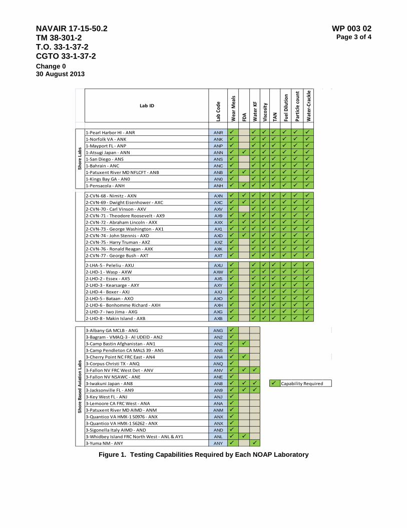
NAVAIR 17-15-50.2 TM 38-301-2 T.O. 33-1-37-2 CGTO 33-1-37-2
WP 003 02 Page 3 of 4
Change 0 30 August 2013
Lab ID
Lab
Code
Wea
r M
eals
FDA
Wat
er K
F
Visc
osit
y
TAN
Fuel
Dilu
tion
Part
icle
cou
nt
Wat
er-C
rack
le
1-Pearl Harbor HI - ANR ANR 1-Norfolk VA - ANK ANK 1-Mayport FL - ANP ANP 1-Atsugi Japan - ANN ANN 1-San Diego - ANS ANS 1-Bahrain - ANC ANC 1-Patuxent River MD NFLCFT - ANB ANB 1-Kings Bay GA - AN0 AN0 1-Pensacola - ANH ANH
2-CVN-68 - Nimitz - AXN AXN 2-CVN-69 - Dwight Eisenhower - AXC AXC 2-CVN-70 - Carl Vinson - AXV AXV 2-CVN-71 - Theodore Roosevelt - AX9 AX9 2-CVN-72 - Abraham Lincoln - AXX AXX 2-CVN-73 - George Washington - AX1 AX1 2-CVN-74 - John Stennis - AXD AXD 2-CVN-75 - Harry Truman - AXZ AXZ 2-CVN-76 - Ronald Reagan - AXK AXK 2-CVN-77 - George Bush - AXT AXT
2-LHA-5 - Peleliu - AXU AXU 2-LHD-1 - Wasp - AXW AXW 2-LHD-2 - Essex - AX5 AX5 2-LHD-3 - Kearsarge - AXY AXY 2-LHD-4 - Boxer - AXJ AXJ 2-LHD-5 - Bataan - AXO AXO 2-LHD-6 - Bonhomme Richard - AXH AXH 2-LHD-7 - Iwo Jima - AXG AXG 2-LHD-8 - Makin Island - AXB AXB
3-Albany GA MCLB - ANG ANG 3-Bagram - VMAQ-3 - Al UDEID - AN2 AN2 3-Camp Bastin Afghanistan - AN1 AN2 3-Camp Pendleton CA MALS 39 - AN5 AN5 3-Cherry Point NC FRC East - AN4 AN4 3-Corpus Christi TX - ANQ ANQ 3-Fallon NV FRC West Det - ANV ANV 3-Fallon NV NSAWC - ANE ANE 3-Iwakuni Japan - AN8 AN8 3-Jacksonville FL - AN9 AN9 3-Key West FL - ANJ ANJ 3-Lemoore CA FRC West - ANA ANA 3-Patuxent River MD AIMD - ANM ANM 3-Quantico VA HMX-1 S0976 - ANX ANX 3-Quantico VA HMX-1 S6262 - ANX ANX 3-Sigonella Italy AIMD - AND AND 3-Whidbey Island FRC North West - ANL & AY1 ANL 3-Yuma NM - ANY ANY
Shor
e La
bsSh
ore
Base
d Av
iatio
n La
bs
Capability Required
Figure 1. Testing Capabilities Required by Each NOAP Laboratory

NAVAIR 17-15-50.2 TM 38-301-2 T.O. 33-1-37-2 CGTO 33-1-37-2
WP 003 02 Page 4 of 4
Change 0 30 August 2013
This Page Intentionally Left Blank

NAVAIR 17-15-50.2 TM 38-301-2 T.O. 33-1-37-2 CGTO 33-1-37-2
WP 003 03 Page 1 of 74
Change 0 30 August 2013
LUBRICANTS ANALYSIS AND RESEARCH APPLICATION (LARA) NOAP LABORATORY MANAGEMENT SOFTWARE OPERATIONS GUIDE
Table of Contents Page 1. Introduction .......................................................................................................................................................................... 2 2. Using LARA .......................................................................................................................................................................... 2 a. LARA Login ................................................................................................................................................................ 2 b. Changing User’s Password ....................................................................................................................................... 3 3. Sample Receiving and Testing ............................................................................................................................................. 4 a. Sample Receipt .......................................................................................................................................................... 4 b. Entering a Sample into LARA .................................................................................................................................... 5 c. Entering Spectrometer Data....................................................................................................................................... 7 d. Entering Physical Property Test Sample Data ........................................................................................................... 8 e. Entering Particle Count Data...................................................................................................................................... 9 f. Entering Findings, Recommendations, and Advice .................................................................................................. 11 g. Adding a component, engine, gearbox or other piece of equipment. ....................................................................... 13 h. Deleting a component. ............................................................................................................................................. 16 i. Modify a Component ................................................................................................................................................ 18 j. Adding a new Unit Identification Code ..................................................................................................................... 19 k. Modify unit identification code .................................................................................................................................. 22 l. Completing/reviewing an existing sample ................................................................................................................ 23 4. Reports. ............................................................................................................................................................................. 25 a. Components Enrolled Report ................................................................................................................................... 25 b. Equipment Samples Log .......................................................................................................................................... 26 c. History Listing Report ............................................................................................................................................... 27 d. JOAP Monthly Workload Summary Report .............................................................................................................. 29 e. Monthly Activity Report ............................................................................................................................................ 30 f. PPM Report ............................................................................................................................................................. 32 g. TEC Report .............................................................................................................................................................. 33 h. Unreported Samples Report .................................................................................................................................... 34 5. TRANSFER FILES .......................................................................................................................................................... 35 a. Create NOAP export data ........................................................................................................................................ 35 b. Transfer by UIC/Component .................................................................................................................................... 37 c. Import transfer files. ................................................................................................................................................. 40 6. EQUIPMENT REQUIRED ............................................................................................................................................... 43 7. SOFTWARE / COMPUTER MAINTENANCE ................................................................................................................. 43 a. Manage users (adding/deleting/modifying users) ..................................................................................................... 43 b. Create Backup ......................................................................................................................................................... 48 c. Purge data ............................................................................................................................................................... 50 d. Sample Options ....................................................................................................................................................... 52 e. Sample count to display on history listing ................................................................................................................ 57 f. Move sample to CSN ............................................................................................................................................... 58 g. Update/consolidate CSN numbers ........................................................................................................................... 61 h. E-mail database to NOAP office .............................................................................................................................. 63 i. Install Instructions .................................................................................................................................................... 63 j. Restore Instructions ................................................................................................................................. 70 8. DEFINITIONS ................................................................................................................................................ 71

NAVAIR 17-15-50.2 TM 38-301-2 T.O. 33-1-37-2 CGTO 33-1-37-2
WP 003 03 Page 2 of 74
Change 0 30 August 2013
1. Introduction.
a. LARA (Lubricants Analysis and Research Application) was designed to make sample reporting quicker and easier for the lab operator, while retaining information about a component. LARA is designed to be used while connected to a Spectrometer, allowing the lab operator to capture sample results directly from the Spectrometer. Currently LARA will not run on NMCI.
b. All data captured and generated from LARA is used to support various Navy programs. The software has
several reports required by Maintenance Officers, Squadrons and other Navy personnel. The lab operator is required to provide results, reports and data as requested by any Department of Defense staff.
c. A central database is maintained by NOAP staff. This database is created by transfer files provided by all
NOAP lab operators. Since data is routinely requested from the NOAP Office, data is required by NOAP lab operators. Each lab operators must regularly upload or email data to the NOAP Office in order for the NOAP Office to report to the Department of Defense.
d. Contact the NOAP Office ([email protected]) with any questions or concerns regarding LARA or oil
analysis. Refer to the WP 003 01 for contact information.
2. Using LARA
a. LARA Login. LARA is installed and available on all Spectrometer computers. The LARA program icon can be seen on the computer’s Desktop.
(1). Double click on the LARA icon and you will see the Login Screen (Figure 1). Enter your username
and password then press OK. If you need a username and password, contact the lab administrator. If no one is assigned the duty of lab administrator, then contact the NOAP Office.
Figure 1. Login Screen
(2). On Tuesday or Friday the NOAP Transfer Reminder message (Figure 2) will appear to remind you to send your data to the NOAP office so that your samples and results can be reported to Navy personnel. Data submission is required by WP 003 01.
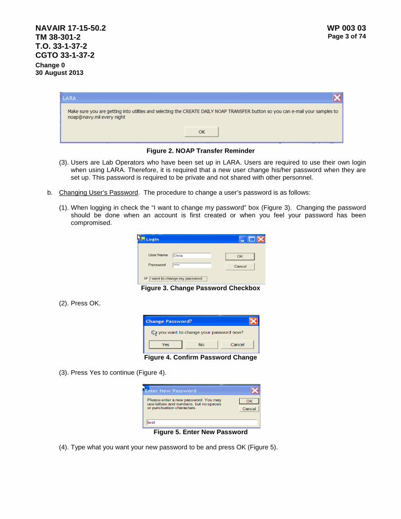
NAVAIR 17-15-50.2 TM 38-301-2 T.O. 33-1-37-2 CGTO 33-1-37-2
WP 003 03 Page 3 of 74
Change 0 30 August 2013
Figure 2. NOAP Transfer Reminder
(3). Users are Lab Operators who have been set up in LARA. Users are required to use their own login when using LARA. Therefore, it is required that a new user change his/her password when they are set up. This password is required to be private and not shared with other personnel.
b. Changing User’s Password. The procedure to change a user’s password is as follows:
(1). When logging in check the “I want to change my password” box (Figure 3). Changing the password
should be done when an account is first created or when you feel your password has been compromised.
Figure 3. Change Password Checkbox
(2). Press OK.
Figure 4. Confirm Password Change
(3). Press Yes to continue (Figure 4).
Figure 5. Enter New Password
(4). Type what you want your new password to be and press OK (Figure 5).

NAVAIR 17-15-50.2 TM 38-301-2 T.O. 33-1-37-2 CGTO 33-1-37-2
WP 003 03 Page 4 of 74
Change 0 30 August 2013
Figure 6. Change Password
(5). Press Yes to verify the new password (Figure 6).
Figure 7. Confirm Password Change
(6). Press OK on the Confirm Password Change screen to continue to sample screen (Figure 7).
3 SAMPLE RECEIVING AND TESTING
a. Sample Receipt. Oil samples are received by the NOAP Lab for testing. The samples will arrive with a
DD 2026 Form. This form will provide the lab operator with the necessary information pertaining to the sample. If the DD 2026 Form is not clearly filled out, or if it appears to have missing data, contact the originator of the sample or the personnel responsible for the sample, and request clarification of missing information. A lab may also request a new DD 2026 be submitted for an existing sample. In order to test oil samples, the lab operator is provided with a series of screens in LARA which assist in identifying the sample, characteristics of the sample, and ultimately reporting results. After logging into LARA you will see the following screen (Figure 8).

NAVAIR 17-15-50.2 TM 38-301-2 T.O. 33-1-37-2 CGTO 33-1-37-2
WP 003 03 Page 5 of 74
Change 0 30 August 2013
Figure 8. Main Screen
b. Entering a Sample into LARA. Procedures to enter a sample (also called “receiving a sample” and
“logging a sample”) are as follows:
(1). Enter a unique sample number created with first character as the last number of the year, followed by the month number (October = O, November = N and December = D) then a sequential number. Example 03001 first sample for the month of March in the year 2010. If the sample number entered has already been used the Sample Number message will appear (Figure 9). Press OK and enter a unique sample number.
Sample 9. Sample Number
(2) Use the pull down to select a CSN (component serial number). Highlight the correct CSN and
press enter.
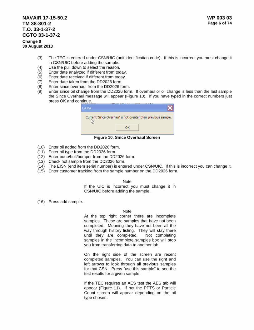
NAVAIR 17-15-50.2 TM 38-301-2 T.O. 33-1-37-2 CGTO 33-1-37-2
WP 003 03 Page 6 of 74
Change 0 30 August 2013
(3) The TEC is entered under CSN/UIC (unit identification code). If this is incorrect you must change it in CSN/UIC before adding the sample.
(4) Use the pull down to select the reason. (5) Enter date analyzed if different from today. (6) Enter date received if different from today. (7) Enter date taken from the DD2026 form. (8) Enter since overhaul from the DD2026 form. (9) Enter since oil change from the DD2026 form. If overhaul or oil change is less than the last sample
the Since Overhaul message will appear (Figure 10). If you have typed in the correct numbers just press OK and continue.
Figure 10. Since Overhaul Screen
(10) Enter oil added from the DD2026 form. (11) Enter oil type from the DD2026 form. (12) Enter buno/hull/bumper from the DD2026 form. (13) Check hot sample from the DD2026 form. (14) The EISN (end item serial number) is entered under CSN/UIC. If this is incorrect you can change it. (15) Enter customer tracking from the sample number on the DD2026 form.
Note
If the UIC is incorrect you must change it in CSN/UIC before adding the sample.
(16) Press add sample.
Note
At the top right corner there are incomplete samples. These are samples that have not been completed. Meaning they have not been all the way through history listing. They will stay there until they are completed. Not completing samples in the incomplete samples box will stop you from transferring data to another lab.
On the right side of the screen are recent completed samples. You can use the right and left arrows to look through all previous samples for that CSN. Press “use this sample” to see the test results for a given sample. If the TEC requires an AES test the AES tab will appear (Figure 11). If not the PPTS or Particle Count screen will appear depending on the oil type chosen.

NAVAIR 17-15-50.2 TM 38-301-2 T.O. 33-1-37-2 CGTO 33-1-37-2
WP 003 03 Page 7 of 74
Change 0 30 August 2013
c. Entering Spectrometer Data. Select manual or automatic: Manual will let you type in the spectrometer
data. Automatic will allow the data to be transmitted directly from the spectrometer. Automatic is preferred. Please ensure all cables are connected to the Spectrometer and LARA computer to perform Automatic data transfer. If there is a problem using this method, contact the NOAP Office immediately.
Figure 11. AES Tab
(1). If automatic is selected press “Get Spectrometer Output” after the “Written to Com1” message
appears on the upper left hand corner of the spectrometer monitor.

NAVAIR 17-15-50.2 TM 38-301-2 T.O. 33-1-37-2 CGTO 33-1-37-2
WP 003 03 Page 8 of 74
Change 0 30 August 2013
Figure 12. AES Manual Entry
(2). If manual is selected, type the spectrometer data into the column to the right of the corresponding
element. If you choose to add spectrometer data without completing the record press the M to save the data and select the next record in the incomplete box. (Figure 12)
(3). If tests are completed press the “Advice” tab and skip to the advice page.
d. Entering Physical Property Test Sample (PPTS) Data. If physical property test data is required, press the
“PPTS” tab and the next screen will appear (Figure 13).
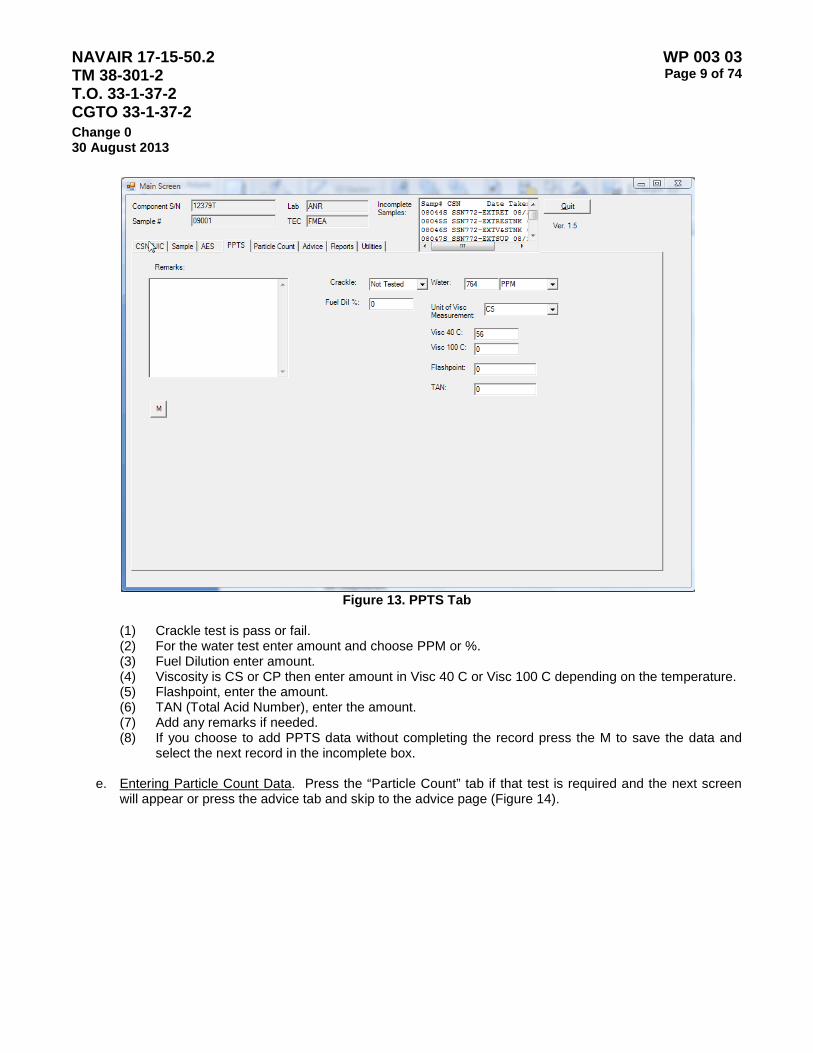
NAVAIR 17-15-50.2 TM 38-301-2 T.O. 33-1-37-2 CGTO 33-1-37-2
WP 003 03 Page 9 of 74
Change 0 30 August 2013
Figure 13. PPTS Tab
(1) Crackle test is pass or fail. (2) For the water test enter amount and choose PPM or %. (3) Fuel Dilution enter amount. (4) Viscosity is CS or CP then enter amount in Visc 40 C or Visc 100 C depending on the temperature. (5) Flashpoint, enter the amount. (6) TAN (Total Acid Number), enter the amount. (7) Add any remarks if needed. (8) If you choose to add PPTS data without completing the record press the M to save the data and
select the next record in the incomplete box.
e. Entering Particle Count Data. Press the “Particle Count” tab if that test is required and the next screen will appear or press the advice tab and skip to the advice page (Figure 14).

NAVAIR 17-15-50.2 TM 38-301-2 T.O. 33-1-37-2 CGTO 33-1-37-2
WP 003 03 Page 10 of 74
Change 0 30 August 2013
Figure 14. Particle Count
(1). Use the pull down to choose the standard. (2). Enter the amounts for all the ranges. (3). Select the Class. (4). Add any remarks if needed. (5). If you choose to add PPTS data without completing the record press the M to save the data and
select the next record in the incomplete box. (6). Press the advice tab to continue to the next screen (Figure 15).
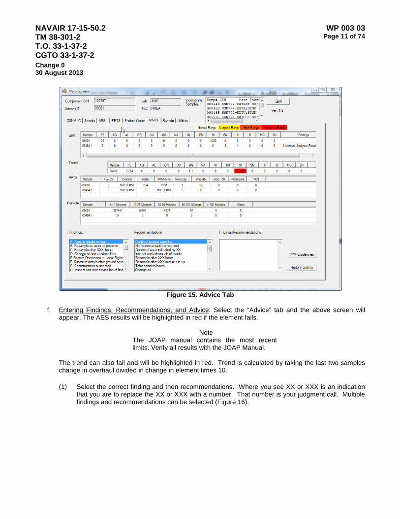
NAVAIR 17-15-50.2 TM 38-301-2 T.O. 33-1-37-2 CGTO 33-1-37-2
WP 003 03 Page 11 of 74
Change 0 30 August 2013
Figure 15. Advice Tab
f. Entering Findings, Recommendations, and Advice. Select the “Advice” tab and the above screen will
appear. The AES results will be highlighted in red if the element fails.
Note The JOAP manual contains the most recent limits. Verify all results with the JOAP Manual.
The trend can also fail and will be highlighted in red. Trend is calculated by taking the last two samples
change in overhaul divided in change in element times 10.
(1) Select the correct finding and then recommendations. Where you see XX or XXX is an indication that you are to replace the XX or XXX with a number. That number is your judgment call. Multiple findings and recommendations can be selected (Figure 16).
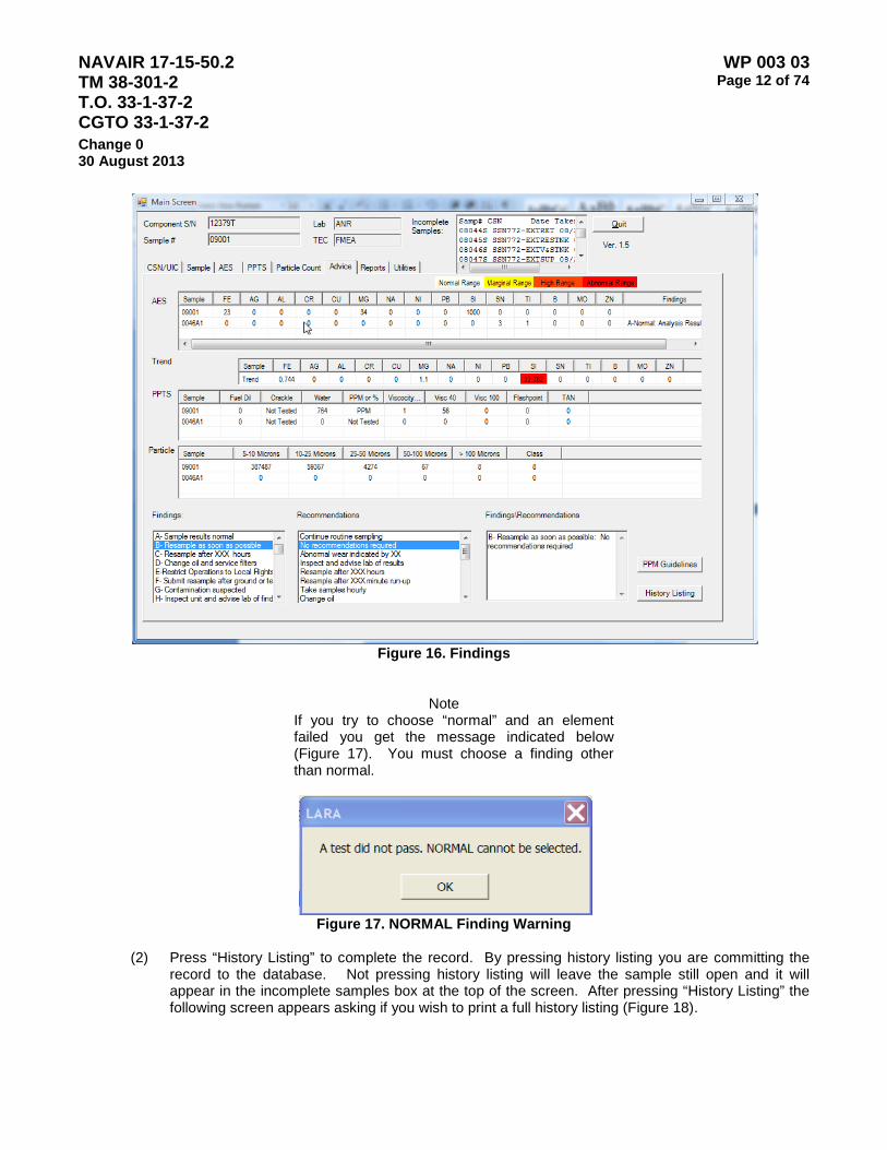
NAVAIR 17-15-50.2 TM 38-301-2 T.O. 33-1-37-2 CGTO 33-1-37-2
WP 003 03 Page 12 of 74
Change 0 30 August 2013
Figure 16. Findings
Note If you try to choose “normal” and an element failed you get the message indicated below (Figure 17). You must choose a finding other than normal.
Figure 17. NORMAL Finding Warning
(2) Press “History Listing” to complete the record. By pressing history listing you are committing the
record to the database. Not pressing history listing will leave the sample still open and it will appear in the incomplete samples box at the top of the screen. After pressing “History Listing” the following screen appears asking if you wish to print a full history listing (Figure 18).
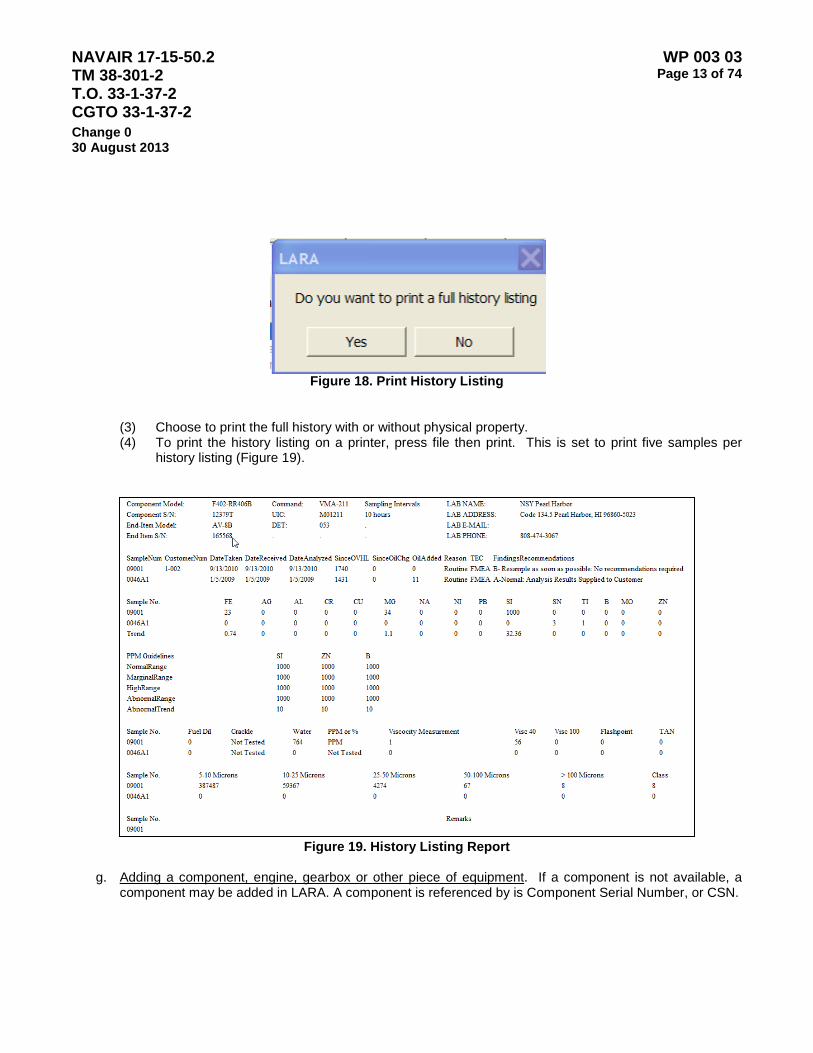
NAVAIR 17-15-50.2 TM 38-301-2 T.O. 33-1-37-2 CGTO 33-1-37-2
WP 003 03 Page 13 of 74
Change 0 30 August 2013
Figure 18. Print History Listing
(3) Choose to print the full history with or without physical property. (4) To print the history listing on a printer, press file then print. This is set to print five samples per
history listing (Figure 19).
Figure 19. History Listing Report
g. Adding a component, engine, gearbox or other piece of equipment. If a component is not available, a
component may be added in LARA. A component is referenced by is Component Serial Number, or CSN.

NAVAIR 17-15-50.2 TM 38-301-2 T.O. 33-1-37-2 CGTO 33-1-37-2
WP 003 03 Page 14 of 74
Change 0 30 August 2013
(1) From the main sample screen press the “CSN/UIC” tab and the following screen will appear (Figure 20). Adding a component is done when you have searched and can’t find the component serial number and have asked for a transfer disk with no response.
Figure 20. CSN/UIC Tab
(2) Select the Add/Modify CSN button. The CSN Screen displays (Figure 21).
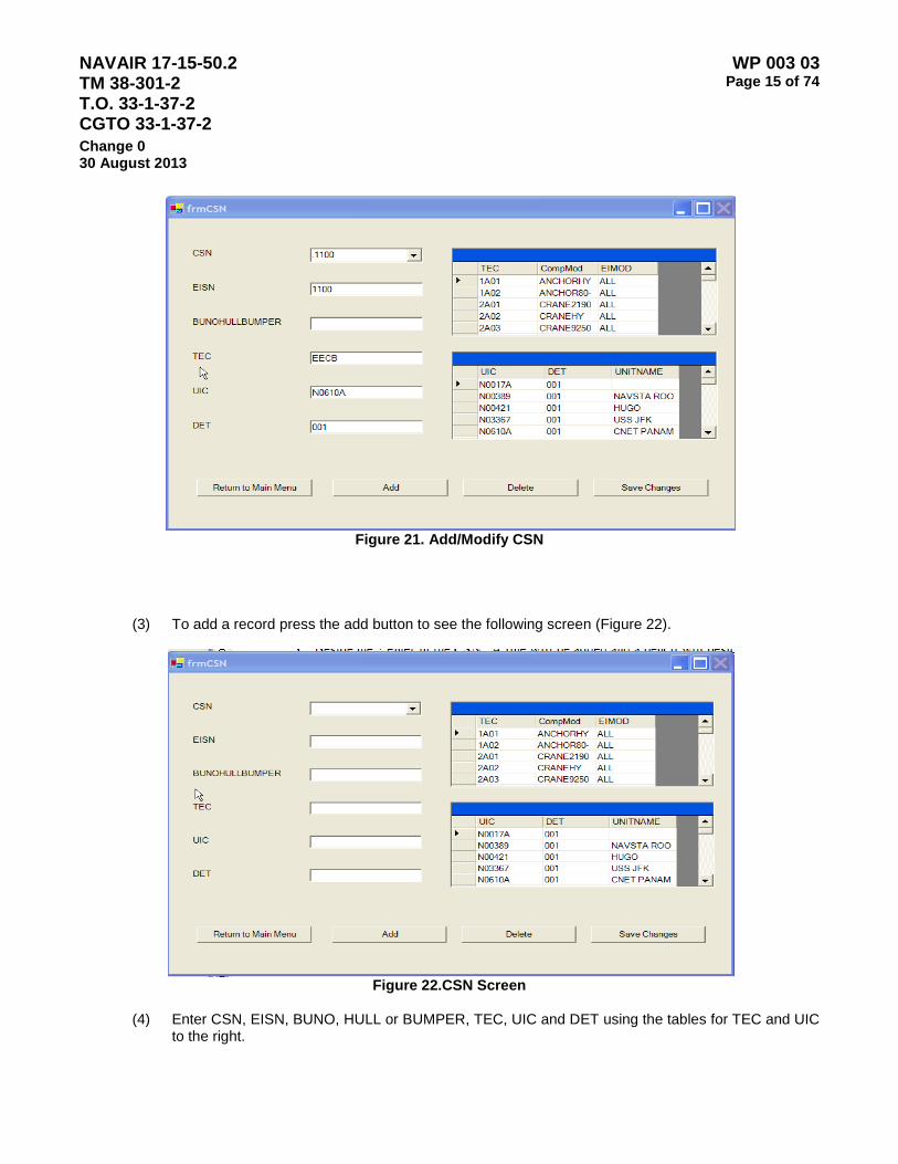
NAVAIR 17-15-50.2 TM 38-301-2 T.O. 33-1-37-2 CGTO 33-1-37-2
WP 003 03 Page 15 of 74
Change 0 30 August 2013
Figure 21. Add/Modify CSN
(3) To add a record press the add button to see the following screen (Figure 22).
Figure 22.CSN Screen
(4) Enter CSN, EISN, BUNO, HULL or BUMPER, TEC, UIC and DET using the tables for TEC and UIC
to the right.

NAVAIR 17-15-50.2 TM 38-301-2 T.O. 33-1-37-2 CGTO 33-1-37-2
WP 003 03 Page 16 of 74
Change 0 30 August 2013
(5) TEC, UIC and DET must exist in the pull downs to the right for record to be added. (6) Press save changes for the record to be saved (Figure 23).
Figure 23. Saved
(7) Press OK.
h. Deleting a component. If a component was added in error, deletion of a component is available in LARA.
(1) From the main screen press the CSN/UIC tab and the following screen will appear (Figure 24). Deleting a component is done only if the component has been taken out of service. Deleting the component will not delete the samples. They will stay in your database until they are purged.
Figure 24. CSN/UIC Tab
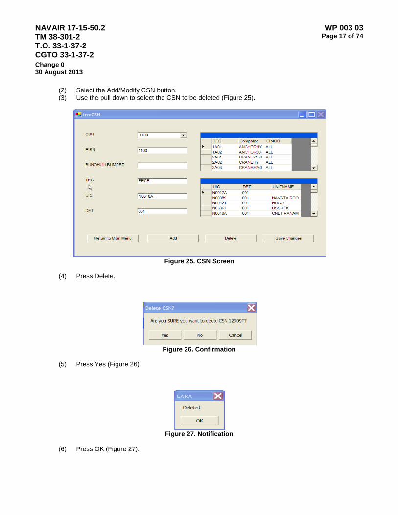
NAVAIR 17-15-50.2 TM 38-301-2 T.O. 33-1-37-2 CGTO 33-1-37-2
WP 003 03 Page 17 of 74
Change 0 30 August 2013
(2) Select the Add/Modify CSN button. (3) Use the pull down to select the CSN to be deleted (Figure 25).
Figure 25. CSN Screen
(4) Press Delete.
Figure 26. Confirmation
(5) Press Yes (Figure 26).
Figure 27. Notification
(6) Press OK (Figure 27).

NAVAIR 17-15-50.2 TM 38-301-2 T.O. 33-1-37-2 CGTO 33-1-37-2
WP 003 03 Page 18 of 74
Change 0 30 August 2013
i. Modify a Component. If a component or CSN required modification, this capability exists in LARA.
(1) From the main screen press the CSN/UIC tab and the following screen will appear (Figure 28).
Figure 28. CSN/UIC Tab
(2) Select the Add/Modify CSN button (Figure 29).

NAVAIR 17-15-50.2 TM 38-301-2 T.O. 33-1-37-2 CGTO 33-1-37-2
WP 003 03 Page 19 of 74
Change 0 30 August 2013
Figure 29. CSN Screen
(3) Use the pull down to select the csn to be changed. (4) Make any changes and press save changes.
Figure 30. Confirmation
(5) Press OK (Figure 30).
j. Adding a new Unit Identification Code. A Unit is defined within LARA to assist tracking components and
equipment with the personnel assigned. The unit is identified by the Unit Identification Code, or UIC.
(1) From the main screen press the CSN/UIC tab and the following screen will appear (Figure 31). Adding a UIC is done when you have searched and can’t find the UIC and have asked for a transfer disk with no response.
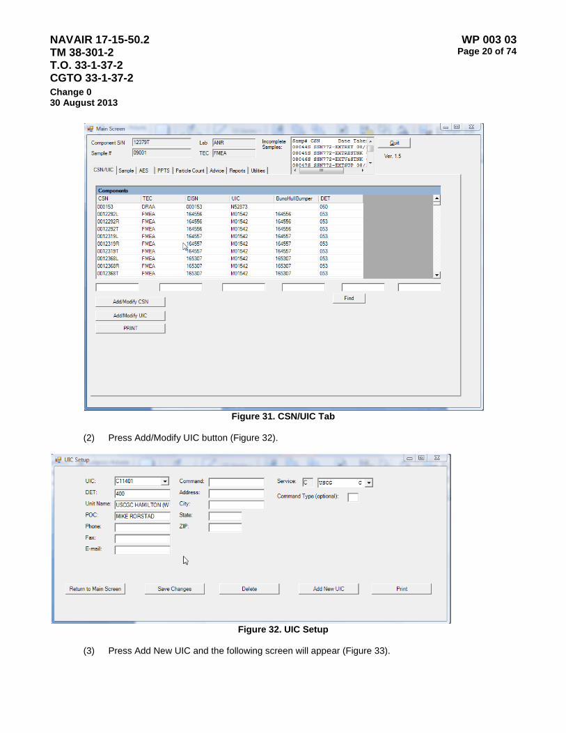
NAVAIR 17-15-50.2 TM 38-301-2 T.O. 33-1-37-2 CGTO 33-1-37-2
WP 003 03 Page 20 of 74
Change 0 30 August 2013
Figure 31. CSN/UIC Tab
(2) Press Add/Modify UIC button (Figure 32).
Figure 32. UIC Setup
(3) Press Add New UIC and the following screen will appear (Figure 33).
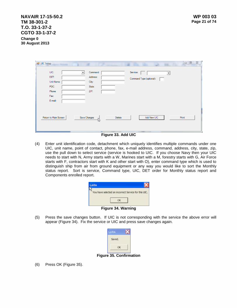
NAVAIR 17-15-50.2 TM 38-301-2 T.O. 33-1-37-2 CGTO 33-1-37-2
WP 003 03 Page 21 of 74
Change 0 30 August 2013
Figure 33. Add UIC
(4) Enter unit identification code, detachment which uniquely identifies multiple commands under one
UIC, unit name, point of contact, phone, fax, e-mail address, command, address, city, state, zip, use the pull down to select service (service is hooked to UIC. If you choose Navy then your UIC needs to start with N, Army starts with a W, Marines start with a M, forestry starts with G, Air Force starts with F, contractors start with K and other start with O), enter command type which is used to distinguish ship from air from ground equipment or any way you would like to sort the Monthly status report. Sort is service, Command type, UIC, DET order for Monthly status report and Components enrolled report.
Figure 34. Warning
(5) Press the save changes button. If UIC is not corresponding with the service the above error will
appear (Figure 34). Fix the service or UIC and press save changes again.
Figure 35. Confirmation
(6) Press OK (Figure 35).
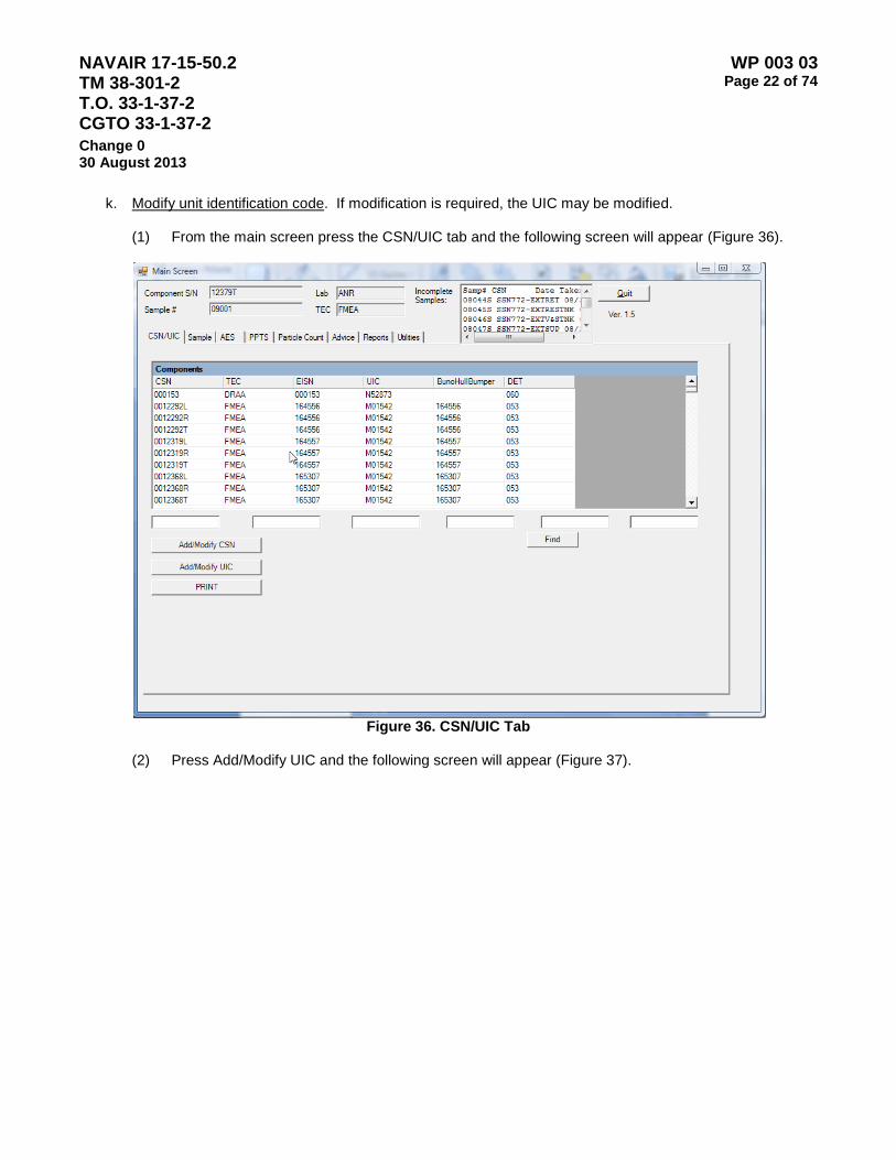
NAVAIR 17-15-50.2 TM 38-301-2 T.O. 33-1-37-2 CGTO 33-1-37-2
WP 003 03 Page 22 of 74
Change 0 30 August 2013
k. Modify unit identification code. If modification is required, the UIC may be modified.
(1) From the main screen press the CSN/UIC tab and the following screen will appear (Figure 36).
Figure 36. CSN/UIC Tab
(2) Press Add/Modify UIC and the following screen will appear (Figure 37).
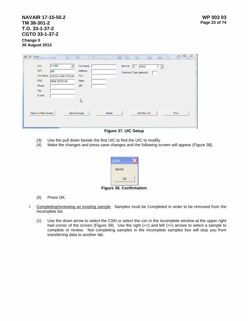
NAVAIR 17-15-50.2 TM 38-301-2 T.O. 33-1-37-2 CGTO 33-1-37-2
WP 003 03 Page 23 of 74
Change 0 30 August 2013
Figure 37. UIC Setup
(3) Use the pull down beside the first UIC to find the UIC to modify. (4) Make the changes and press save changes and the following screen will appear (Figure 38).
Figure 38. Confirmation
(5) Press OK.
l. Completing/reviewing an existing sample. Samples must be Completed in order to be removed from the
Incomplete list.
(1) Use the down arrow to select the CSN or select the csn in the incomplete window at the upper right had corner of the screen (Figure 39). Use the right (<<) and left (>>) arrows to select a sample to complete or review. Not completing samples in the incomplete samples box will stop you from transferring data to another lab.
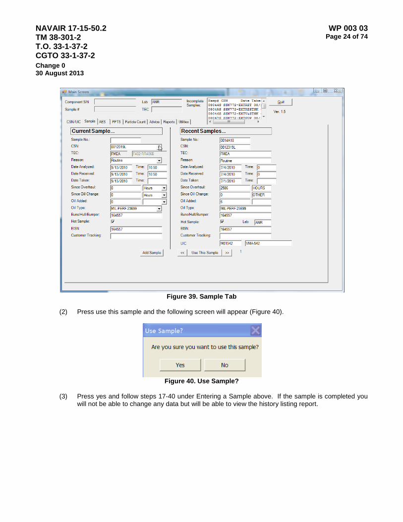
NAVAIR 17-15-50.2 TM 38-301-2 T.O. 33-1-37-2 CGTO 33-1-37-2
WP 003 03 Page 24 of 74
Change 0 30 August 2013
Figure 39. Sample Tab
(2) Press use this sample and the following screen will appear (Figure 40).
Figure 40. Use Sample?
(3) Press yes and follow steps 17-40 under Entering a Sample above. If the sample is completed you
will not be able to change any data but will be able to view the history listing report.
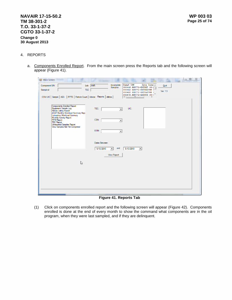
NAVAIR 17-15-50.2 TM 38-301-2 T.O. 33-1-37-2 CGTO 33-1-37-2
WP 003 03 Page 25 of 74
Change 0 30 August 2013
4. REPORTS
a. Components Enrolled Report. From the main screen press the Reports tab and the following screen will
appear (Figure 41).
Figure 41. Reports Tab
(1) Click on components enrolled report and the following screen will appear (Figure 42). Components
enrolled is done at the end of every month to show the command what components are in the oil program, when they were last sampled, and if they are delinquent.
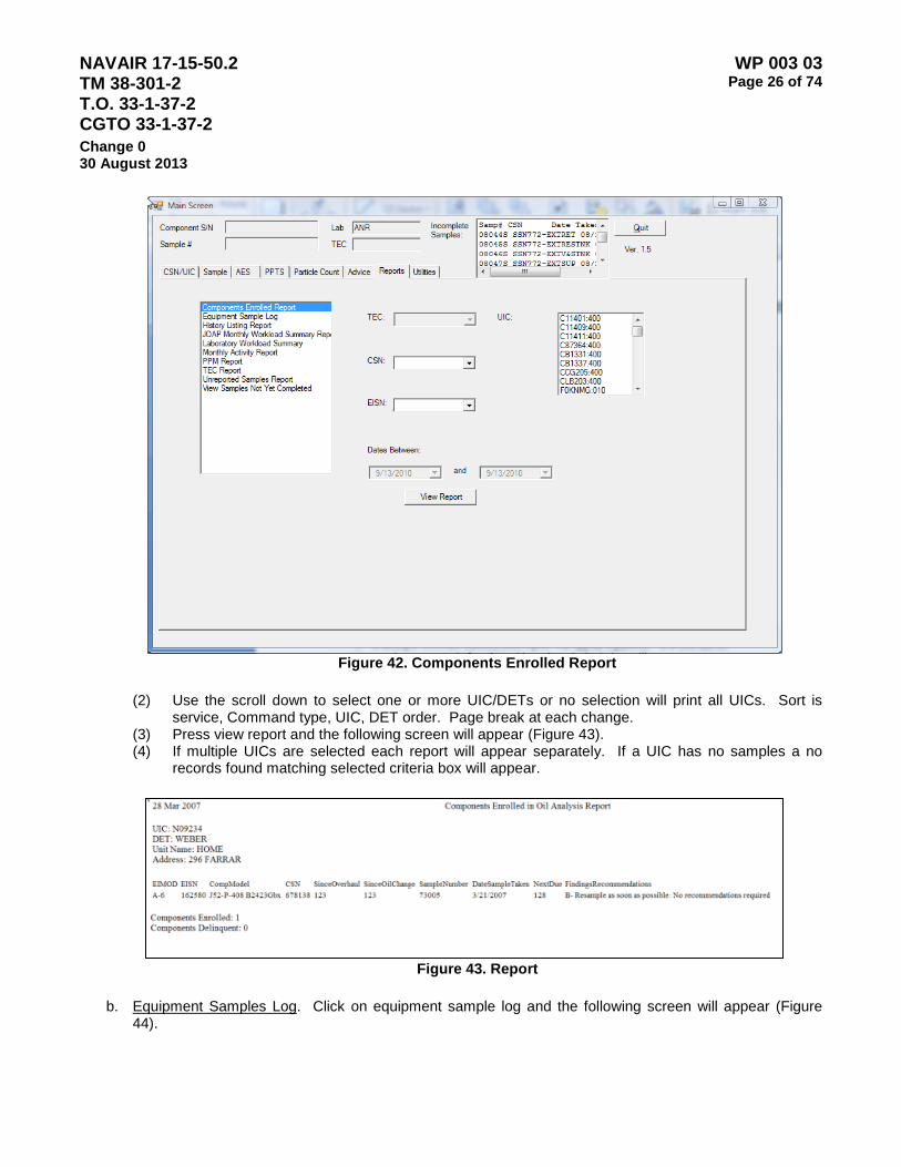
NAVAIR 17-15-50.2 TM 38-301-2 T.O. 33-1-37-2 CGTO 33-1-37-2
WP 003 03 Page 26 of 74
Change 0 30 August 2013
Figure 42. Components Enrolled Report
(2) Use the scroll down to select one or more UIC/DETs or no selection will print all UICs. Sort is
service, Command type, UIC, DET order. Page break at each change. (3) Press view report and the following screen will appear (Figure 43). (4) If multiple UICs are selected each report will appear separately. If a UIC has no samples a no
records found matching selected criteria box will appear.
Figure 43. Report
b. Equipment Samples Log. Click on equipment sample log and the following screen will appear (Figure
44).
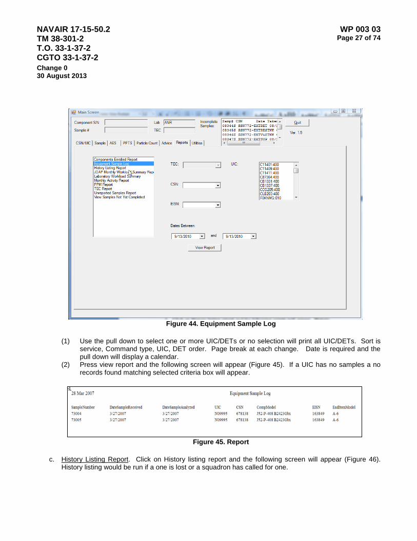
NAVAIR 17-15-50.2 TM 38-301-2 T.O. 33-1-37-2 CGTO 33-1-37-2
WP 003 03 Page 27 of 74
Change 0 30 August 2013
Figure 44. Equipment Sample Log
(1) Use the pull down to select one or more UIC/DETs or no selection will print all UIC/DETs. Sort is
service, Command type, UIC, DET order. Page break at each change. Date is required and the pull down will display a calendar.
(2) Press view report and the following screen will appear (Figure 45). If a UIC has no samples a no records found matching selected criteria box will appear.
Figure 45. Report
c. History Listing Report. Click on History listing report and the following screen will appear (Figure 46).
History listing would be run if a one is lost or a squadron has called for one.
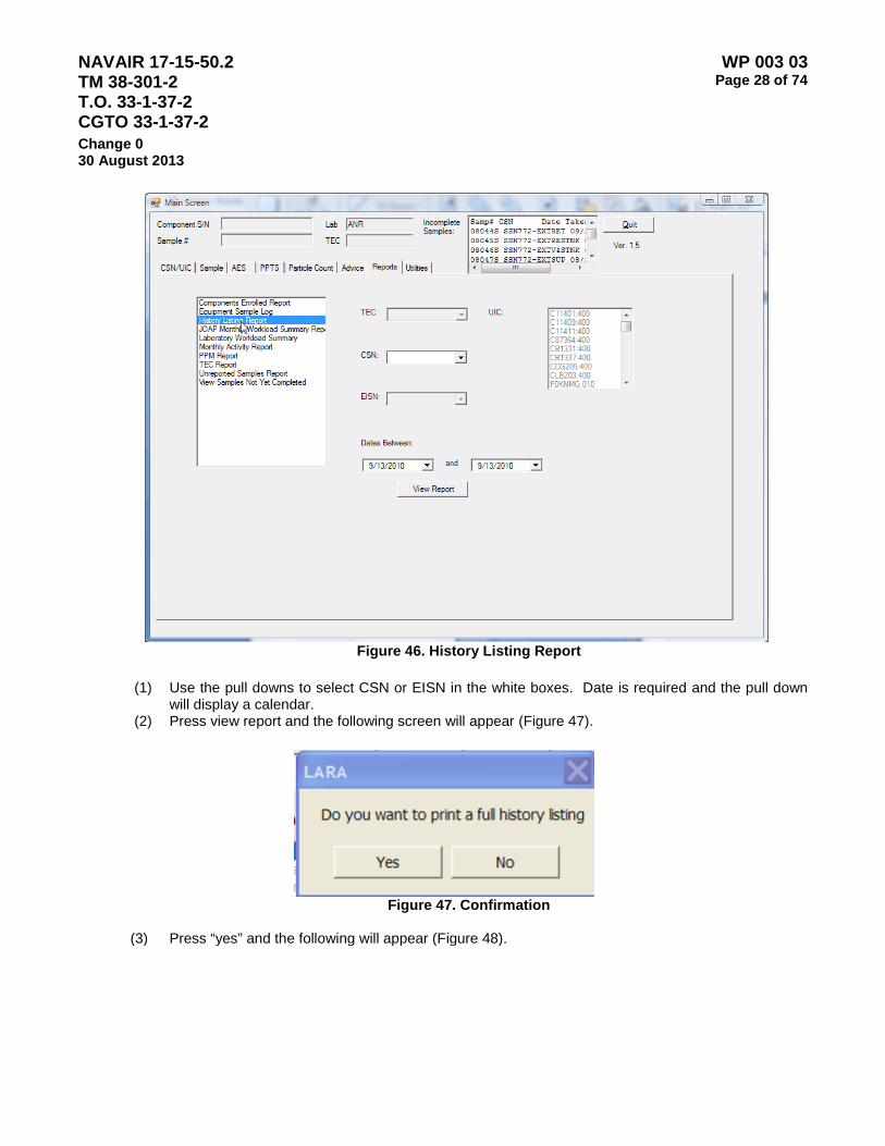
NAVAIR 17-15-50.2 TM 38-301-2 T.O. 33-1-37-2 CGTO 33-1-37-2
WP 003 03 Page 28 of 74
Change 0 30 August 2013
Figure 46. History Listing Report
(1) Use the pull downs to select CSN or EISN in the white boxes. Date is required and the pull down
will display a calendar. (2) Press view report and the following screen will appear (Figure 47).
Figure 47. Confirmation
(3) Press “yes” and the following will appear (Figure 48).
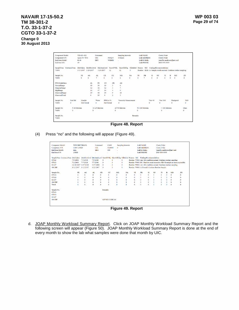
NAVAIR 17-15-50.2 TM 38-301-2 T.O. 33-1-37-2 CGTO 33-1-37-2
WP 003 03 Page 29 of 74
Change 0 30 August 2013
Figure 48. Report
(4) Press “no” and the following will appear (Figure 49).
Figure 49. Report
d. JOAP Monthly Workload Summary Report. Click on JOAP Monthly Workload Summary Report and the following screen will appear (Figure 50). JOAP Monthly Workload Summary Report is done at the end of every month to show the lab what samples were done that month by UIC.
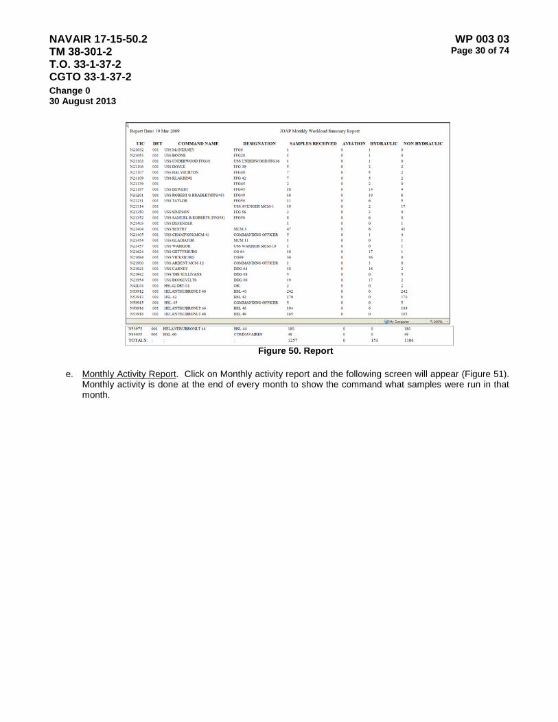
NAVAIR 17-15-50.2 TM 38-301-2 T.O. 33-1-37-2 CGTO 33-1-37-2
WP 003 03 Page 30 of 74
Change 0 30 August 2013
Figure 50. Report
e. Monthly Activity Report. Click on Monthly activity report and the following screen will appear (Figure 51).
Monthly activity is done at the end of every month to show the command what samples were run in that month.

NAVAIR 17-15-50.2 TM 38-301-2 T.O. 33-1-37-2 CGTO 33-1-37-2
WP 003 03 Page 31 of 74
Change 0 30 August 2013
Figure 51. Monthly Activity Report
(1) Use the pull down to select one or more UIC/DETs or no selection will print all UIC/DETs. Sort is service, Command type, UIC, DET order. Page break at each change. Date is required and the pull down will display a calendar.
(2) Press view report and the following screen will appear (Figure 52). If a UIC has no samples a no records found matching selected criteria box will appear.
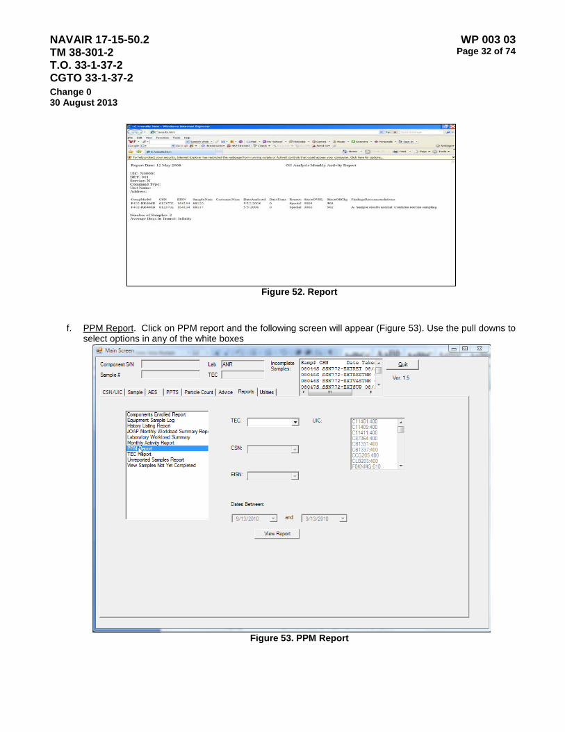
NAVAIR 17-15-50.2 TM 38-301-2 T.O. 33-1-37-2 CGTO 33-1-37-2
WP 003 03 Page 32 of 74
Change 0 30 August 2013
Figure 52. Report
f. PPM Report. Click on PPM report and the following screen will appear (Figure 53). Use the pull downs to
select options in any of the white boxes
Figure 53. PPM Report

NAVAIR 17-15-50.2 TM 38-301-2 T.O. 33-1-37-2 CGTO 33-1-37-2
WP 003 03 Page 33 of 74
Change 0 30 August 2013
(1) To print all the PPM tables leave the white boxes blank. If all the white boxes are left blank the file will go directly to the printer.
(2) Press view report and the following screen will appear (Figure 54).
Figure 54. Report
g. TEC Report. Click on TEC report and the following screen will appear (Figure 55).
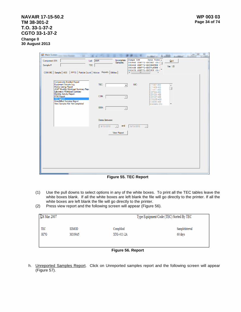
NAVAIR 17-15-50.2 TM 38-301-2 T.O. 33-1-37-2 CGTO 33-1-37-2
WP 003 03 Page 34 of 74
Change 0 30 August 2013
Figure 55. TEC Report
(1) Use the pull downs to select options in any of the white boxes. To print all the TEC tables leave the white boxes blank. If all the white boxes are left blank the file will go directly to the printer. If all the white boxes are left blank the file will go directly to the printer.
(2) Press view report and the following screen will appear (Figure 56).
Figure 56. Report
h. Unreported Samples Report. Click on Unreported samples report and the following screen will appear
(Figure 57).
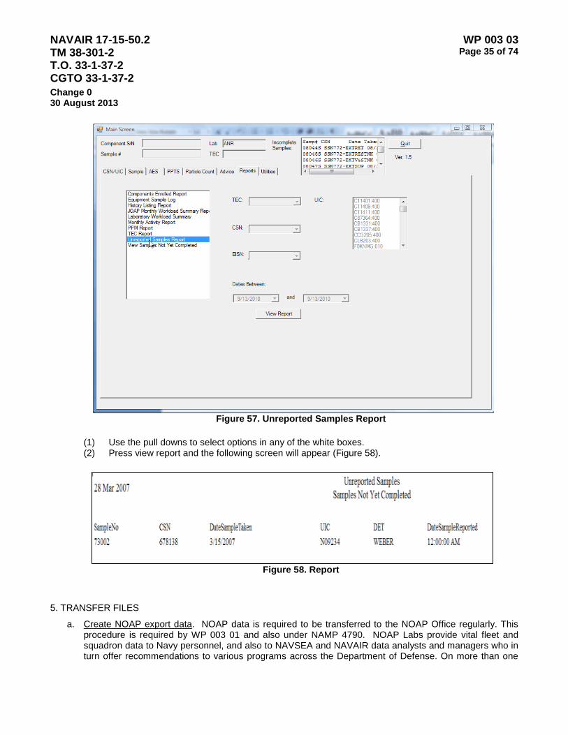
NAVAIR 17-15-50.2 TM 38-301-2 T.O. 33-1-37-2 CGTO 33-1-37-2
WP 003 03 Page 35 of 74
Change 0 30 August 2013
Figure 57. Unreported Samples Report
(1) Use the pull downs to select options in any of the white boxes. (2) Press view report and the following screen will appear (Figure 58).
Figure 58. Report
5. TRANSFER FILES
a. Create NOAP export data. NOAP data is required to be transferred to the NOAP Office regularly. This procedure is required by WP 003 01 and also under NAMP 4790. NOAP Labs provide vital fleet and squadron data to Navy personnel, and also to NAVSEA and NAVAIR data analysts and managers who in turn offer recommendations to various programs across the Department of Defense. On more than one

NAVAIR 17-15-50.2 TM 38-301-2 T.O. 33-1-37-2 CGTO 33-1-37-2
WP 003 03 Page 36 of 74
Change 0 30 August 2013
occasion, NOAP data has saved the lives of Navy personnel, and avoided additional hardship, costs and workload to Navy personnel. NOAP Labs provide a tremendous service to many levels throughout the Navy, by accurately assessing equipment health, and reducing the risk of equipment failures.
(1). From the main sample screen press the Utilities tab and the following screen will appear (Figure 59)
Figure 59. Main Screen – Utilities Tab
(2) Press create daily NOAP transfer button (Figure 60).

NAVAIR 17-15-50.2 TM 38-301-2 T.O. 33-1-37-2 CGTO 33-1-37-2
WP 003 03 Page 37 of 74
Change 0 30 August 2013
Figure 60. NOAP Export
(3) Use the pull down to select the drive the export will go to then enter the number of days to export. If
the number of days since last sent is unknown to the lab operator, enter 730 days (two years). This will provide the NOAP office with sufficient time to fill in any gaps in data.
(4) Press create NOAP export then send the file to the noap@ navy.mil.
Note SharePoint has been provided as a web portal to receive transfer files. All transfer files may be uploaded to SharePoint, if the site is accessible from the NOAP Lab’s location.
b. Transfer by UIC/Component. If a squadron or UIC requests their data, it can be provided by creating a series of transfer files.
(1). From the main sample screen press the Utilities tab and the following screen will appear (Figure
61).
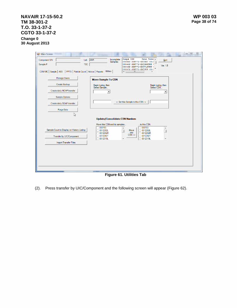
NAVAIR 17-15-50.2 TM 38-301-2 T.O. 33-1-37-2 CGTO 33-1-37-2
WP 003 03 Page 38 of 74
Change 0 30 August 2013
Figure 61. Utilities Tab
(2). Press transfer by UIC/Component and the following screen will appear (Figure 62).
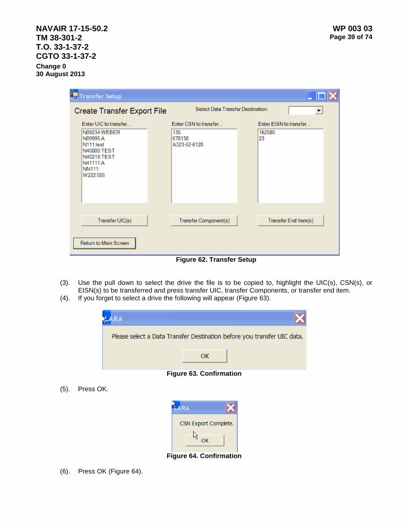
NAVAIR 17-15-50.2 TM 38-301-2 T.O. 33-1-37-2 CGTO 33-1-37-2
WP 003 03 Page 39 of 74
Change 0 30 August 2013
Figure 62. Transfer Setup
(3). Use the pull down to select the drive the file is to be copied to, highlight the UIC(s), CSN(s), or EISN(s) to be transferred and press transfer UIC, transfer Components, or transfer end item.
(4). If you forget to select a drive the following will appear (Figure 63).
Figure 63. Confirmation
(5). Press OK.
Figure 64. Confirmation
(6). Press OK (Figure 64).

NAVAIR 17-15-50.2 TM 38-301-2 T.O. 33-1-37-2 CGTO 33-1-37-2
WP 003 03 Page 40 of 74
Change 0 30 August 2013
c. Import transfer files. When a squadron or UIC arrives and wishes their history to be available in LARA,
they will provide you with the appropriate transfer files to import.
(1). From the main sample screen press the Utilities tab and the following screen will appear (Figure 65).
Figure 65. Utilities Tab
(2). Press import transfer files and the following screen will appear (Figure 66).

NAVAIR 17-15-50.2 TM 38-301-2 T.O. 33-1-37-2 CGTO 33-1-37-2
WP 003 03 Page 41 of 74
Change 0 30 August 2013
Figure 66. Import Transfer Data
(3). Use the pull down to select the drive the file will go to, press browse and the following screen will appear (Figure 67).
Figure 67. Required File
(4). Press OK.
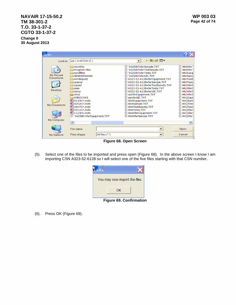
NAVAIR 17-15-50.2 TM 38-301-2 T.O. 33-1-37-2 CGTO 33-1-37-2
WP 003 03 Page 42 of 74
Change 0 30 August 2013
Figure 68. Open Screen
(5). Select one of the files to be imported and press open (Figure 68). In the above screen I know I am importing CSN A323-52-6128 so I will select one of the five files starting with that CSN number.
Figure 69. Confirmation
(6). Press OK (Figure 69).
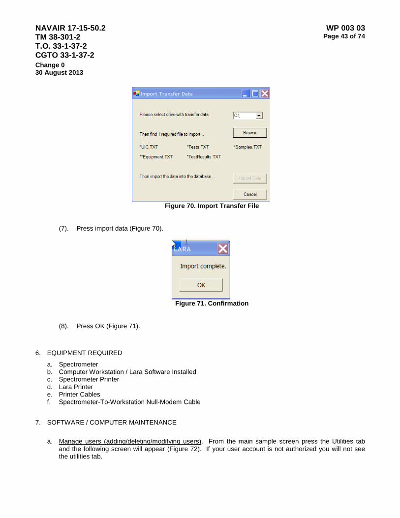
NAVAIR 17-15-50.2 TM 38-301-2 T.O. 33-1-37-2 CGTO 33-1-37-2
WP 003 03 Page 43 of 74
Change 0 30 August 2013
Figure 70. Import Transfer File
(7). Press import data (Figure 70).
Figure 71. Confirmation
(8). Press OK (Figure 71).
6. EQUIPMENT REQUIRED
a. Spectrometer b. Computer Workstation / Lara Software Installed c. Spectrometer Printer d. Lara Printer e. Printer Cables f. Spectrometer-To-Workstation Null-Modem Cable
7. SOFTWARE / COMPUTER MAINTENANCE
a. Manage users (adding/deleting/modifying users). From the main sample screen press the Utilities tab
and the following screen will appear (Figure 72). If your user account is not authorized you will not see the utilities tab.

NAVAIR 17-15-50.2 TM 38-301-2 T.O. 33-1-37-2 CGTO 33-1-37-2
WP 003 03 Page 44 of 74
Change 0 30 August 2013
Figure 72. Utilities Tab
(1). Press Manage users and the following screen will appear (Figure 73).

NAVAIR 17-15-50.2 TM 38-301-2 T.O. 33-1-37-2 CGTO 33-1-37-2
WP 003 03 Page 45 of 74
Change 0 30 August 2013
Figure 73. Manage Users
(2). To reset a password highlight the users to be reset and press the reset button, the following screen
will appear (Figure 74).
Figure 74. Reset User Password
(3). Press Yes.
Figure 75. Change Password
(4). Press OK and the password will be changed to password (Figure 75). (5). To modify a user’s information highlight the user to be modified and press manage user. The
information for that user will be filled in to the right.

NAVAIR 17-15-50.2 TM 38-301-2 T.O. 33-1-37-2 CGTO 33-1-37-2
WP 003 03 Page 46 of 74
Change 0 30 August 2013
Figure 76. Manage Users
(6). Make the changes needed and press commit changes (Figure 76).
Figure 77. Confirmation
(7). Press OK (Figure 77). (8). To delete a users highlight the user to be deleted and press delete user.
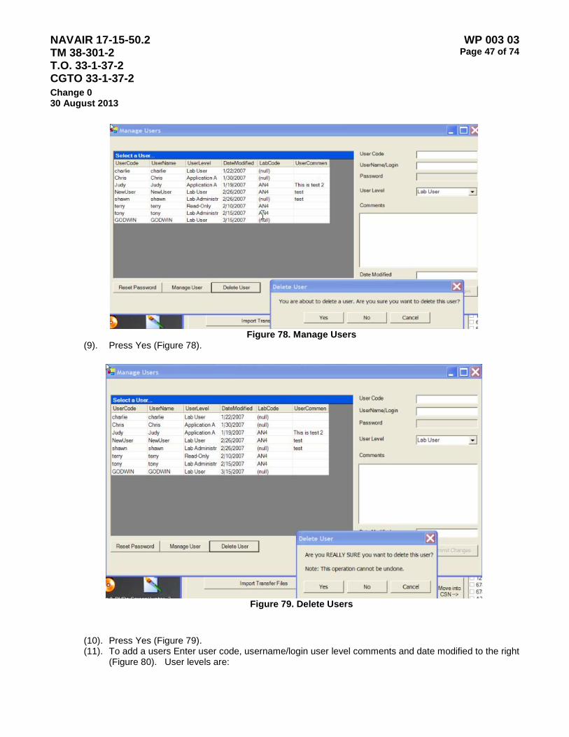
NAVAIR 17-15-50.2 TM 38-301-2 T.O. 33-1-37-2 CGTO 33-1-37-2
WP 003 03 Page 47 of 74
Change 0 30 August 2013
Figure 78. Manage Users
(9). Press Yes (Figure 78).
Figure 79. Delete Users
(10). Press Yes (Figure 79). (11). To add a users Enter user code, username/login user level comments and date modified to the right
(Figure 80). User levels are:
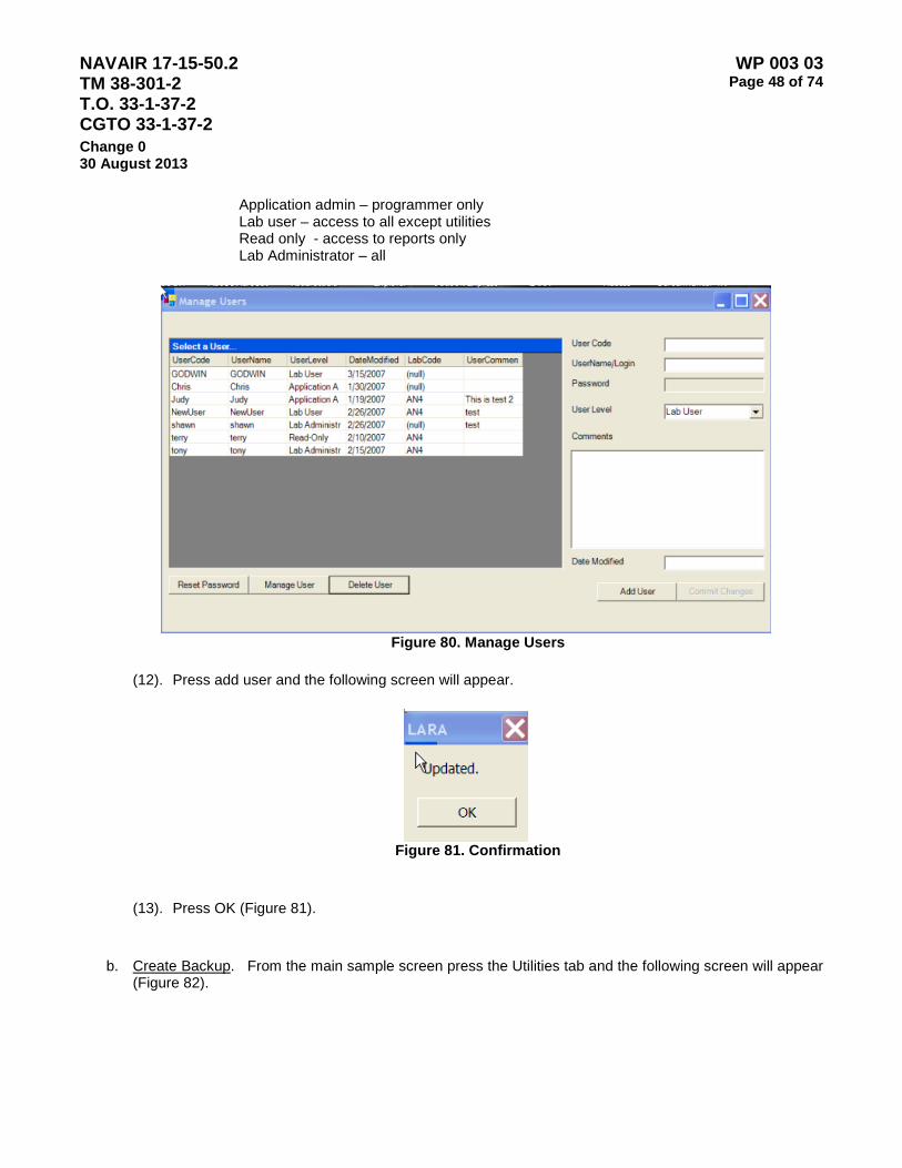
NAVAIR 17-15-50.2 TM 38-301-2 T.O. 33-1-37-2 CGTO 33-1-37-2
WP 003 03 Page 48 of 74
Change 0 30 August 2013
Application admin – programmer only Lab user – access to all except utilities Read only - access to reports only Lab Administrator – all
Figure 80. Manage Users
(12). Press add user and the following screen will appear.
Figure 81. Confirmation
(13). Press OK (Figure 81).
b. Create Backup. From the main sample screen press the Utilities tab and the following screen will appear
(Figure 82).

NAVAIR 17-15-50.2 TM 38-301-2 T.O. 33-1-37-2 CGTO 33-1-37-2
WP 003 03 Page 49 of 74
Change 0 30 August 2013
Figure 82. Create Backup
Note
Backups Must be Performed Daily
(1). Press create backup.
Figure 83. Database Backup
(2). Use the pull down to select the drive the backup is to be copied to (Figure 83).

NAVAIR 17-15-50.2 TM 38-301-2 T.O. 33-1-37-2 CGTO 33-1-37-2
WP 003 03 Page 50 of 74
Change 0 30 August 2013
Figure 84. Database Backup
(3). Press create backup (Figure 84).
Figure 85. Data Backup
(4). Press OK (Figure 85).
c. Purge data. From the main sample screen press the Utilities tab and the following screen will appear (Figure 86).
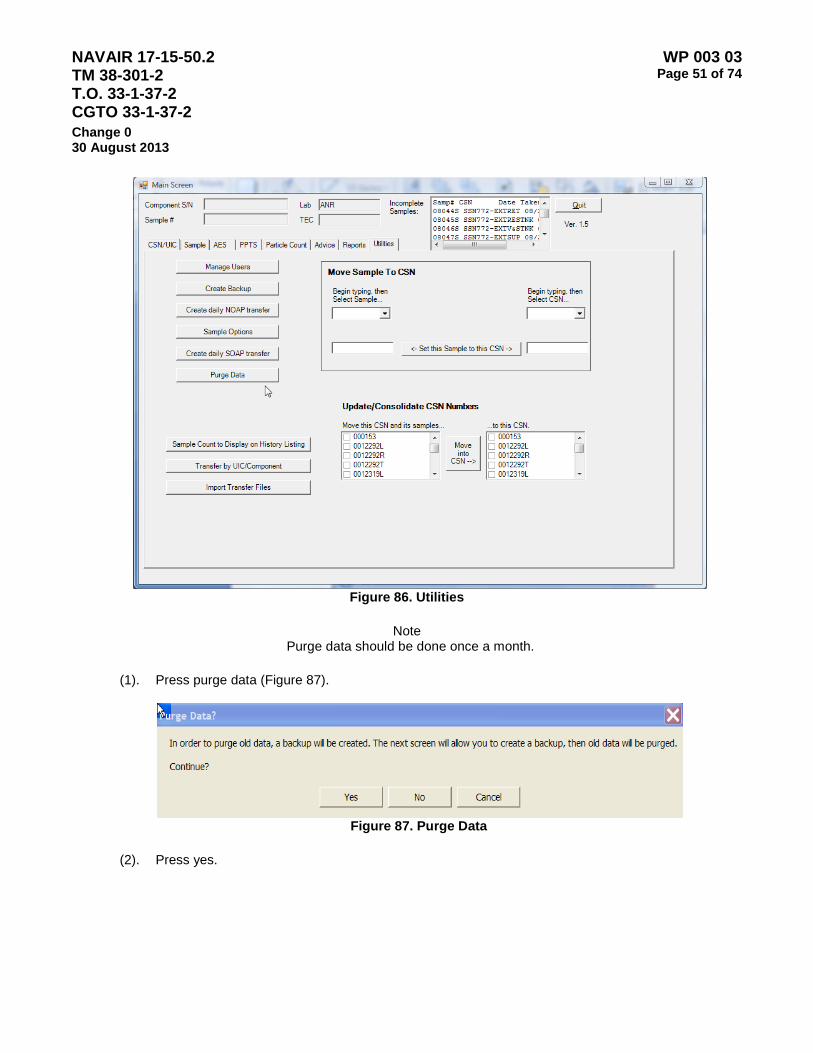
NAVAIR 17-15-50.2 TM 38-301-2 T.O. 33-1-37-2 CGTO 33-1-37-2
WP 003 03 Page 51 of 74
Change 0 30 August 2013
Figure 86. Utilities
Note
Purge data should be done once a month.
(1). Press purge data (Figure 87).
Figure 87. Purge Data
(2). Press yes.
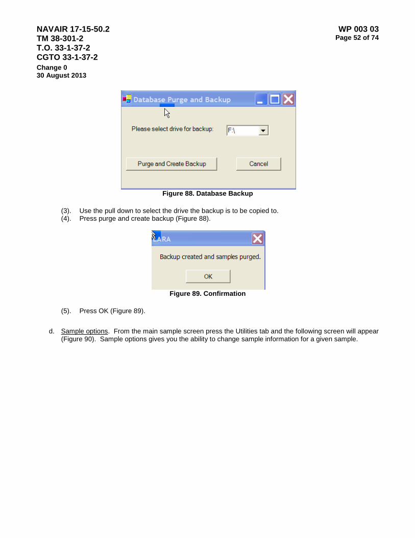
NAVAIR 17-15-50.2 TM 38-301-2 T.O. 33-1-37-2 CGTO 33-1-37-2
WP 003 03 Page 52 of 74
Change 0 30 August 2013
Figure 88. Database Backup
(3). Use the pull down to select the drive the backup is to be copied to. (4). Press purge and create backup (Figure 88).
Figure 89. Confirmation
(5). Press OK (Figure 89).
d. Sample options. From the main sample screen press the Utilities tab and the following screen will appear
(Figure 90). Sample options gives you the ability to change sample information for a given sample.
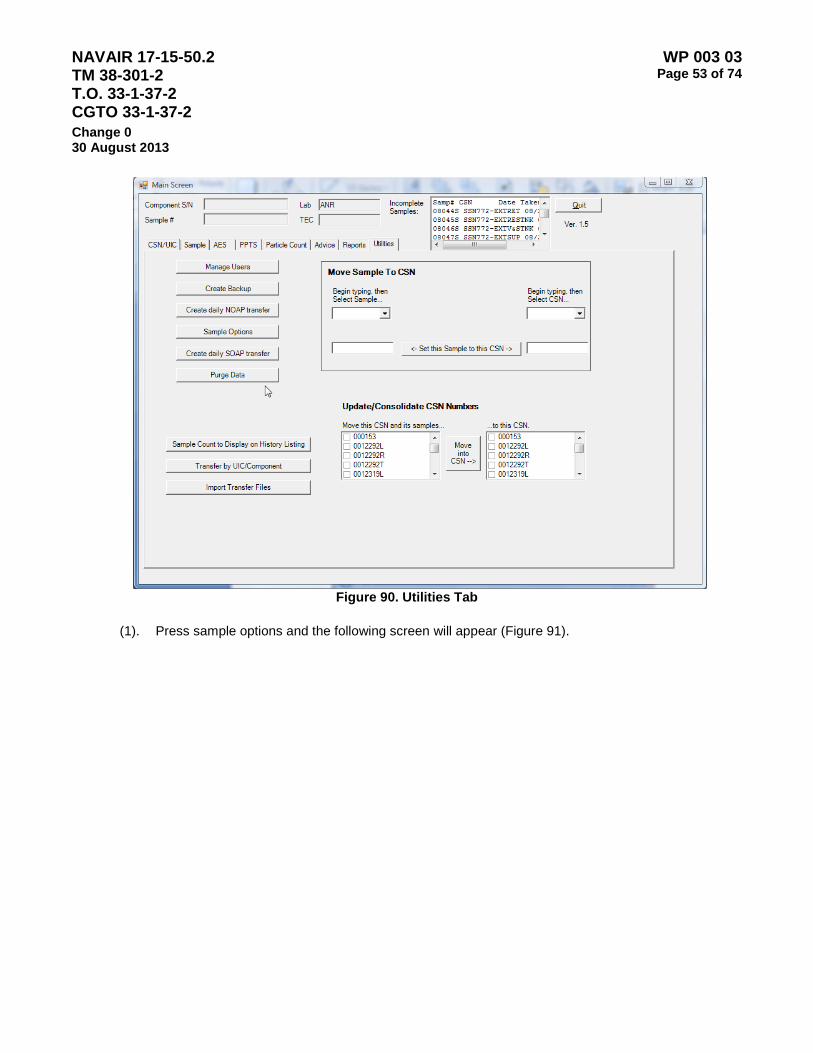
NAVAIR 17-15-50.2 TM 38-301-2 T.O. 33-1-37-2 CGTO 33-1-37-2
WP 003 03 Page 53 of 74
Change 0 30 August 2013
Figure 90. Utilities Tab
(1). Press sample options and the following screen will appear (Figure 91).
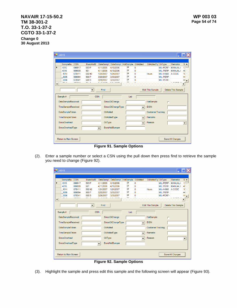
NAVAIR 17-15-50.2 TM 38-301-2 T.O. 33-1-37-2 CGTO 33-1-37-2
WP 003 03 Page 54 of 74
Change 0 30 August 2013
Figure 91. Sample Options
(2). Enter a sample number or select a CSN using the pull down then press find to retrieve the sample
you need to change (Figure 92).
Figure 92. Sample Options
(3). Highlight the sample and press edit this sample and the following screen will appear (Figure 93).
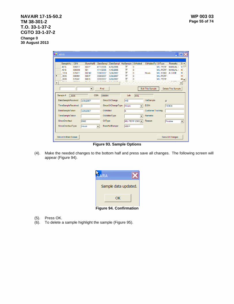
NAVAIR 17-15-50.2 TM 38-301-2 T.O. 33-1-37-2 CGTO 33-1-37-2
WP 003 03 Page 55 of 74
Change 0 30 August 2013
Figure 93. Sample Options
(4). Make the needed changes to the bottom half and press save all changes. The following screen will
appear (Figure 94).
Figure 94. Confirmation
(5). Press OK. (6). To delete a sample highlight the sample (Figure 95).
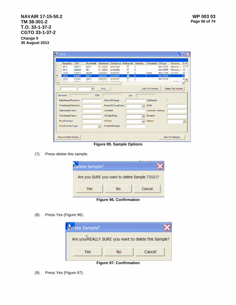
NAVAIR 17-15-50.2 TM 38-301-2 T.O. 33-1-37-2 CGTO 33-1-37-2
WP 003 03 Page 56 of 74
Change 0 30 August 2013
Figure 95. Sample Options
(7). Press delete this sample.
Figure 96. Confirmation
(8). Press Yes (Figure 96).
Figure 97. Confirmation
(9). Press Yes (Figure 97).
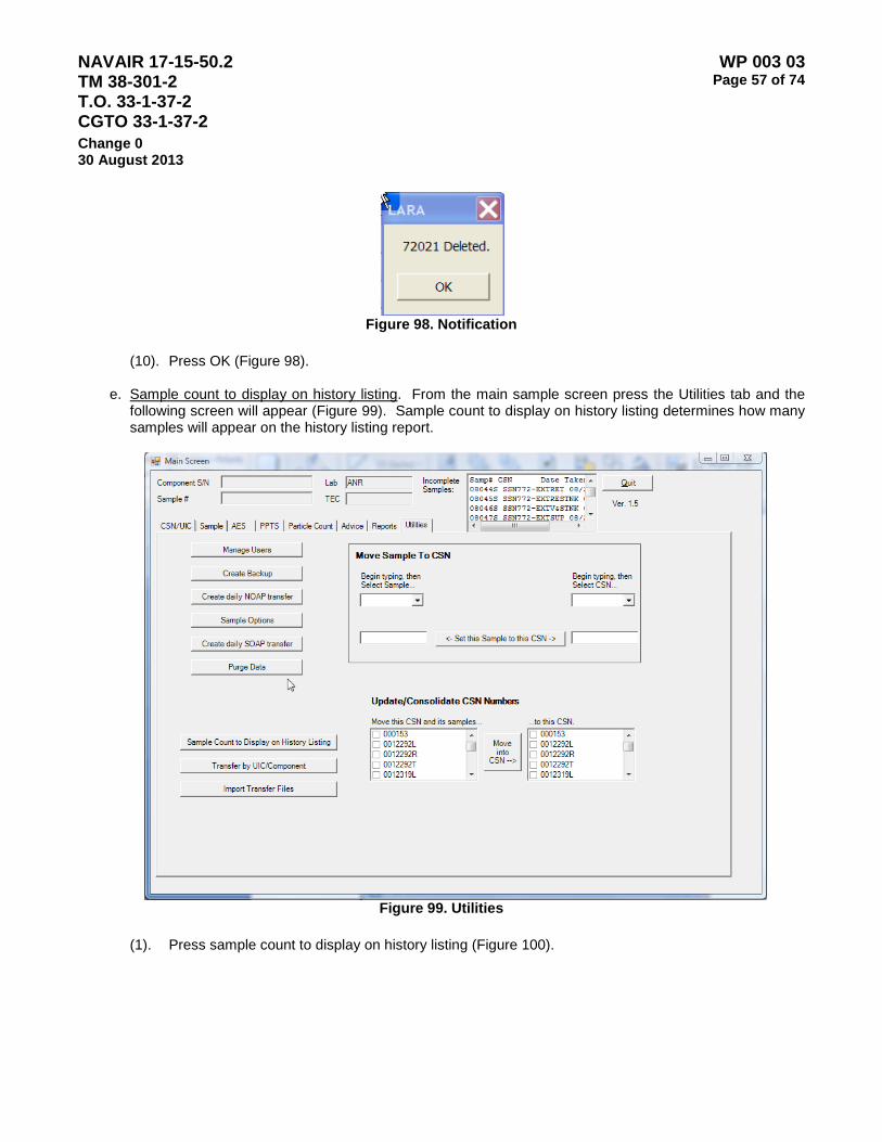
NAVAIR 17-15-50.2 TM 38-301-2 T.O. 33-1-37-2 CGTO 33-1-37-2
WP 003 03 Page 57 of 74
Change 0 30 August 2013
Figure 98. Notification
(10). Press OK (Figure 98).
e. Sample count to display on history listing. From the main sample screen press the Utilities tab and the
following screen will appear (Figure 99). Sample count to display on history listing determines how many samples will appear on the history listing report.
Figure 99. Utilities
(1). Press sample count to display on history listing (Figure 100).
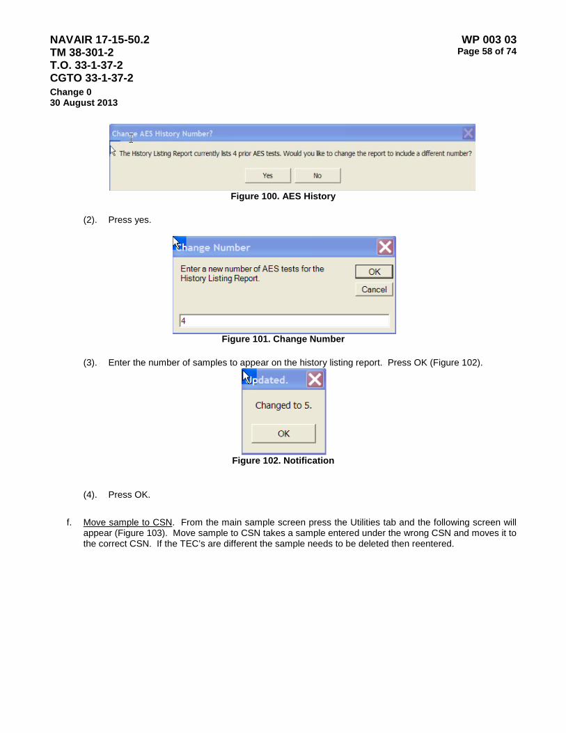
NAVAIR 17-15-50.2 TM 38-301-2 T.O. 33-1-37-2 CGTO 33-1-37-2
WP 003 03 Page 58 of 74
Change 0 30 August 2013
Figure 100. AES History
(2). Press yes.
Figure 101. Change Number
(3). Enter the number of samples to appear on the history listing report. Press OK (Figure 102).
Figure 102. Notification
(4). Press OK.
f. Move sample to CSN. From the main sample screen press the Utilities tab and the following screen will
appear (Figure 103). Move sample to CSN takes a sample entered under the wrong CSN and moves it to the correct CSN. If the TEC’s are different the sample needs to be deleted then reentered.

NAVAIR 17-15-50.2 TM 38-301-2 T.O. 33-1-37-2 CGTO 33-1-37-2
WP 003 03 Page 59 of 74
Change 0 30 August 2013
Figure 103. Utilities Tab
(1). Use the pull down on the left to select the sample number to be moved. Use the pull down to right
to select the CSN to receive the sample.

NAVAIR 17-15-50.2 TM 38-301-2 T.O. 33-1-37-2 CGTO 33-1-37-2
WP 003 03 Page 60 of 74
Change 0 30 August 2013
Figure 104. Utilities Tab
(2). Press set the sample to this CSN (Figure 104).
Figure 105. Move Sample to CSN
(3). Press Yes (Figure 105). (4). If the two CSNs have different TECs this message will appear. The sample can not be moved to
that component. You must delete the sample and redo it.

NAVAIR 17-15-50.2 TM 38-301-2 T.O. 33-1-37-2 CGTO 33-1-37-2
WP 003 03 Page 61 of 74
Change 0 30 August 2013
Figure 106. Notification
(5). Press OK (Figure 106).
Figure 107. Confirmation
(6). Press OK (Figure 107).
g. Update/consolidate CSN numbers. From the main sample screen press the Utilities tab and the following screen will appear (Figure 108). Update/consolidate CSN numbers takes all the samples entered under the wrong CSN and moves it to the correct CSN. Update/consolidate CSN numbers takes all of the samples associated with a CSN and moves them to another existing CSN. An example of why this would be used is a transfer disk brought CSN A232521653 into your system. You have that CSN but under the correct CSN of A232-52-1653. Update/consolidate CSN numbers would merge the A232521653 samples under A232-52-1653 with the correct CSN. If the TEC’s are different the TEC needs to be changed to the accepting TEC.

NAVAIR 17-15-50.2 TM 38-301-2 T.O. 33-1-37-2 CGTO 33-1-37-2
WP 003 03 Page 62 of 74
Change 0 30 August 2013
Figure 108. Utilities Tab
(1). Select the CSN on the right (the wrong one) and the one on the left (the correct one) and press move into CSN (Figure 109).
Figure 109. Update Data
(2). Press Yes.

NAVAIR 17-15-50.2 TM 38-301-2 T.O. 33-1-37-2 CGTO 33-1-37-2
WP 003 03 Page 63 of 74
Change 0 30 August 2013
Figure 110. Confirmation (3). Press OK (Figure 110).
h. E-mail database to NOAP office. When there are problems with your database you need to call NOAP
and they may ask you to e-mail your database.
(1). Get into my computer (2). Select folder options (3). Choose file type (4). Click on advanced (5). Check always show extensions (6). Put in the diskette or external hard drive to a computer. (7). Double click on my computer (8). Double click c: drive (9). Double click lara_vb (10). Double click lara (11). Right click on lara_db.mdb (12). Select copy (13). Double click on my computer (14). Double click on a: drive, or external hard drive (15). Right click and select paste (16). Right click on lara_db.mdb (17). Select rename (18). Change mdb to txt (19). Press enter (20). E-mail the file to the NOAP office, [email protected].
i. Install Instructions. Call the NOAP office to make sure you have the most current version.
(1). Place the CD in the CDROM of the Oasis computer or laptop. (2). Double click on my computer. (3). Double click on the CDROM drive (Figure 111).
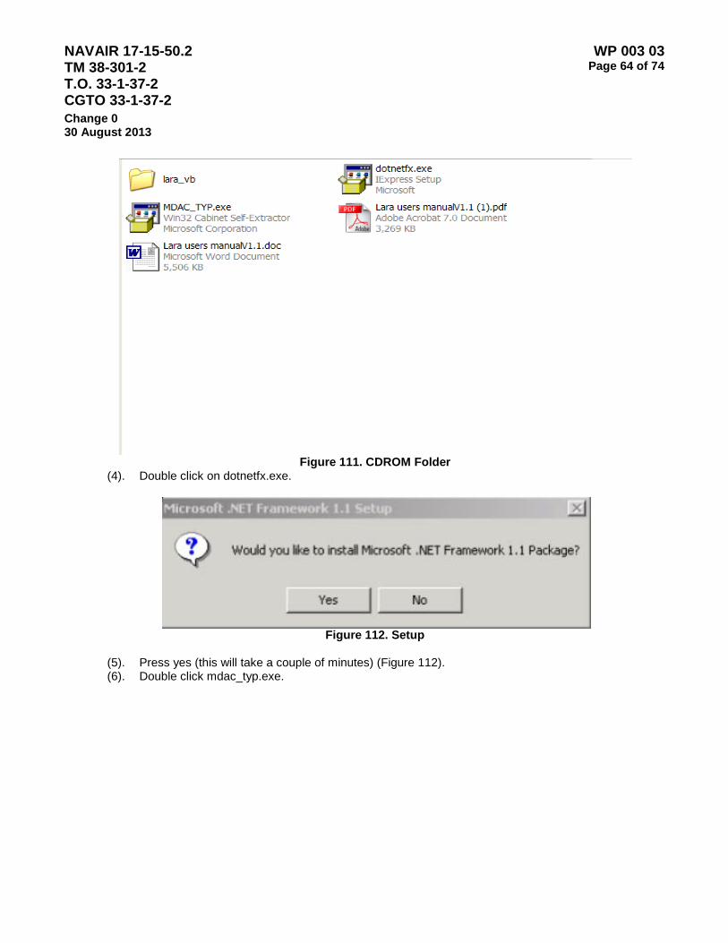
NAVAIR 17-15-50.2 TM 38-301-2 T.O. 33-1-37-2 CGTO 33-1-37-2
WP 003 03 Page 64 of 74
Change 0 30 August 2013
Figure 111. CDROM Folder
(4). Double click on dotnetfx.exe.
Figure 112. Setup
(5). Press yes (this will take a couple of minutes) (Figure 112). (6). Double click mdac_typ.exe.
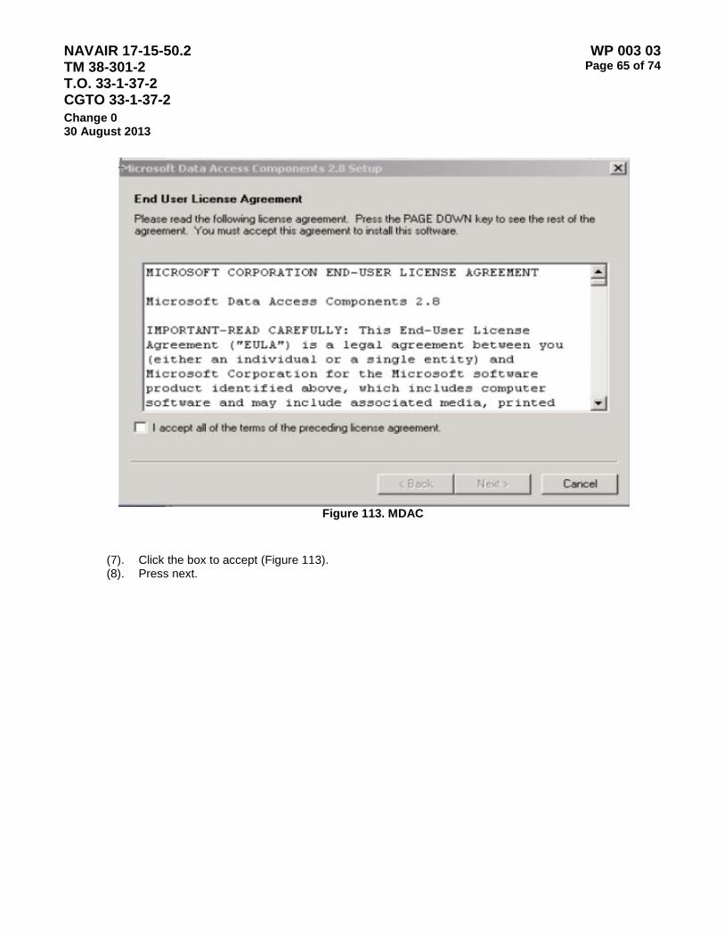
NAVAIR 17-15-50.2 TM 38-301-2 T.O. 33-1-37-2 CGTO 33-1-37-2
WP 003 03 Page 65 of 74
Change 0 30 August 2013
Figure 113. MDAC
(7). Click the box to accept (Figure 113). (8). Press next.
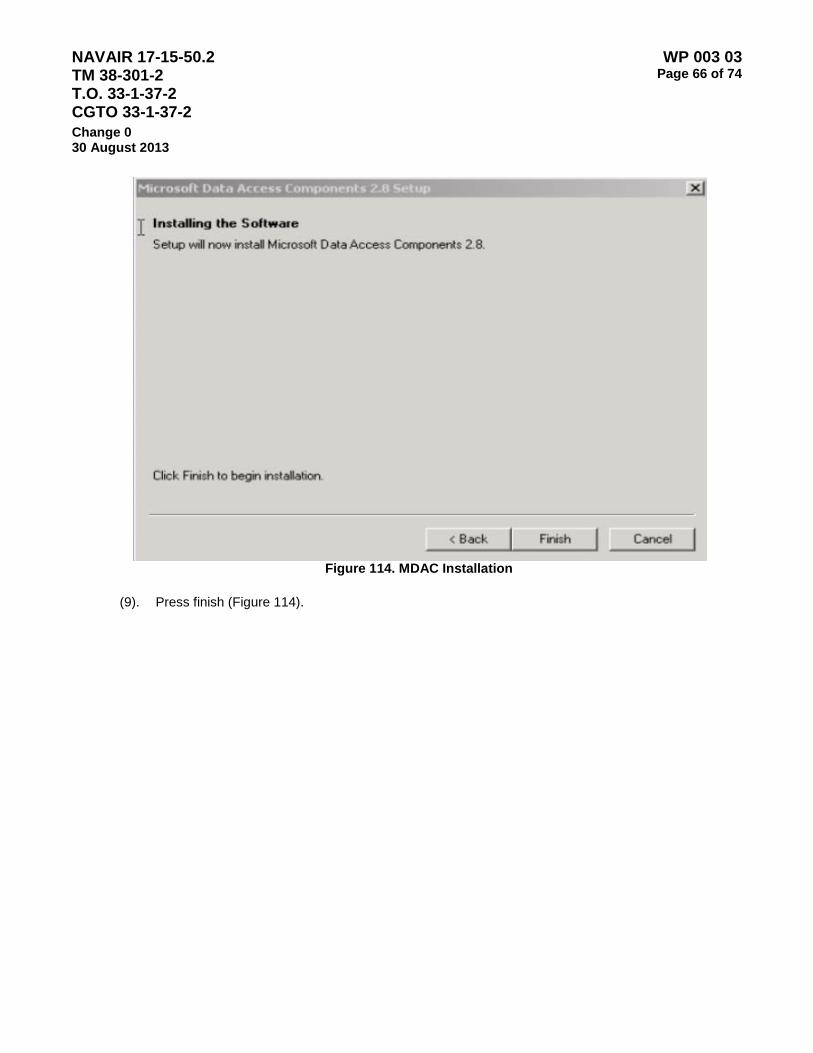
NAVAIR 17-15-50.2 TM 38-301-2 T.O. 33-1-37-2 CGTO 33-1-37-2
WP 003 03 Page 66 of 74
Change 0 30 August 2013
Figure 114. MDAC Installation
(9). Press finish (Figure 114).
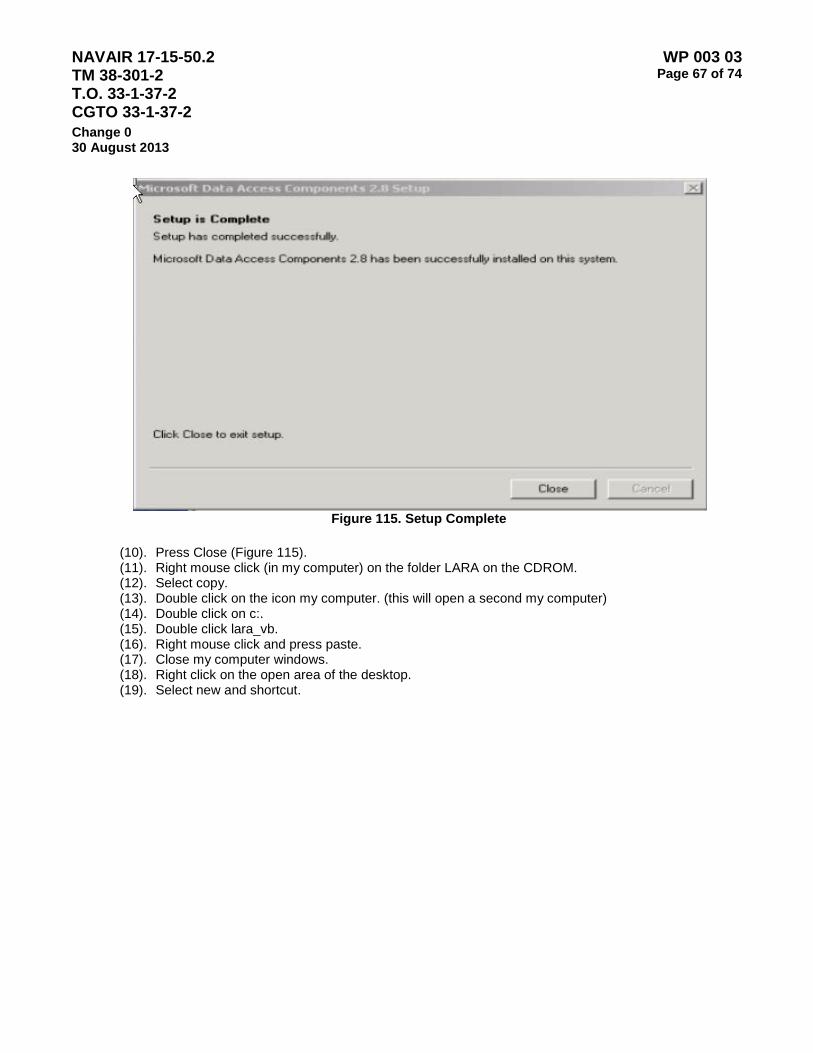
NAVAIR 17-15-50.2 TM 38-301-2 T.O. 33-1-37-2 CGTO 33-1-37-2
WP 003 03 Page 67 of 74
Change 0 30 August 2013
Figure 115. Setup Complete
(10). Press Close (Figure 115). (11). Right mouse click (in my computer) on the folder LARA on the CDROM. (12). Select copy. (13). Double click on the icon my computer. (this will open a second my computer) (14). Double click on c:. (15). Double click lara_vb. (16). Right mouse click and press paste. (17). Close my computer windows. (18). Right click on the open area of the desktop. (19). Select new and shortcut.

NAVAIR 17-15-50.2 TM 38-301-2 T.O. 33-1-37-2 CGTO 33-1-37-2
WP 003 03 Page 68 of 74
Change 0 30 August 2013
Figure 116. Shortcut Wizard
(20). Press the browse button (Figure 116).

NAVAIR 17-15-50.2 TM 38-301-2 T.O. 33-1-37-2 CGTO 33-1-37-2
WP 003 03 Page 69 of 74
Change 0 30 August 2013
Figure 117. Browse
(21). Double click c:. (22). Double click LARA_VB. (23). Double click LARA. (24). Double click LARA.exe (25). Press OK (Figure 117).

NAVAIR 17-15-50.2 TM 38-301-2 T.O. 33-1-37-2 CGTO 33-1-37-2
WP 003 03 Page 70 of 74
Change 0 30 August 2013
Figure 118. Create Shortcut
(26). Press NEXT (Figure 118). (27). Press finish.
J. Restore Instructions. Since you have been doing your daily backups this will be a snap. If you are
backing up to an external hard drive, zip drive or diskette, put the latest one in. The backups are created with the date and the extension mdb. (1). Right mouse click (in my computer) on the mdb file. This mdb file will be called the date you last
backed up. Exp. 012209.mdb. I last backed up January 22 of 2009. (2). Select copy. (3). Double click on the icon my computer. (this will open a second my computer) (4). Double click on c:. (5). Double click on c:\lara_vb. (6). Double click on c:\lara. (7). Right mouse click and press paste. (8). Right click on lara_db.mdb (9). Press delete. (10). Select yes. (11). Right click on the mdb you just copied and select rename (12). Type in lara_db.mdb if you see the mdb on the box. If you don’t see mdb following the date just
type in lara_db. (13). Press enter.
NAVAIR 17-15-50.2 TM 38-301-2 T.O. 33-1-37-2 CGTO 33-1-37-2
WP 003 03 Page 71 of 74
Change 0 30 August 2013
8. DEFINITIONS
5-10 microns – Displayed on the Particle count screen and History Listing report. Numeric field entered from
data generated from the particle counter machine. 10-25 microns – Displayed on the Particle count screen and History Listing report. Numeric field entered
from data generated from the particle counter machine. 25-50 microns – Displayed on the Particle count screen and History Listing report. Numeric field entered
from data generated from the particle counter machine. 50-100 microns – Displayed on the Particle count screen and History Listing report. Numeric field entered
from data generated from the particle counter machine. (>) 100 microns – Displayed on the Particle count screen and History Listing report. Numeric field entered
from data generated from the particle counter machine. Abnormal Range – Displayed on the History Listing report and PPM range report. Numeric field from the
JOAP manual corresponding to the range of numbers unacceptable for a specific TEC. Used to determine if a sample failed.
Abnormal Trend – Displayed on the History Listing report and PPM range report. Numeric field from the JOAP manual corresponding to unacceptable trend for a specific TEC. Used to determine if a sample failed.
Address – Displayed on the UIC setup screen, Monthly Activity report, and Components Enrolled report. Address is the street or PO box of the unit.
Advice – Displayed on the main screen. Tab, when pressed allows findings and recommendations to be selected and by pressing history listing the record is saved and completed.
AES - Displayed on the main screen. Tab, when pressed allows spectrometer data to be entered or transferred into the sample.
Automatic – Displayed on the AES screen. When pressed allows spectrometer data to be transferred into the sample.
Average Days in Transit – Displayed on the Monthly Activity report. BunoHullBumper - Displayed on the CSN setup screen. Bunohullbumper is the buno number, hull number
or bumper number depending on if the component comes from a plane, ship or truck. Entered from DD2026.
Buno/Hull/Bumper - Displayed on the sample screen. Buno/hull/bumper is the buno number, hull number or bumper number depending on if the component comes from a plane, ship or truck.
City - Displayed on the UIC setup screen. City is the city of the unit. Class – Displayed on the Particle count screen and History Listing report. Numeric field entered from data
generated from the particle counter machine. Command - Displayed on the UIC setup screen and History listing report. Usually filled in by commanding
officer of the unit. Command Type - Displayed on the UIC setup screen. Used for a sort to cause a page break. Sort is
service, Command type, UIC, DET order. CompMod - Displayed on the TEC report. CompMod is the component model for the component that
corresponds to the TEC and end item model number. Comp Model - Displayed on the History listing report, Monthly Activity report, Components Enrolled report,
and Equipment Sample Log. Comp Model is the component model for the component that corresponds to the TEC and end item model number.
Component S/N - Displayed on the History listing report and main screen. Components S/N is the component serial number for the component.
Components Delinquent - Displayed on the Components Enrolled report. Displays the number of samples past due.
Components Enrolled - Displayed on the Components Enrolled report. Displays the number of samples in the JOAP program.
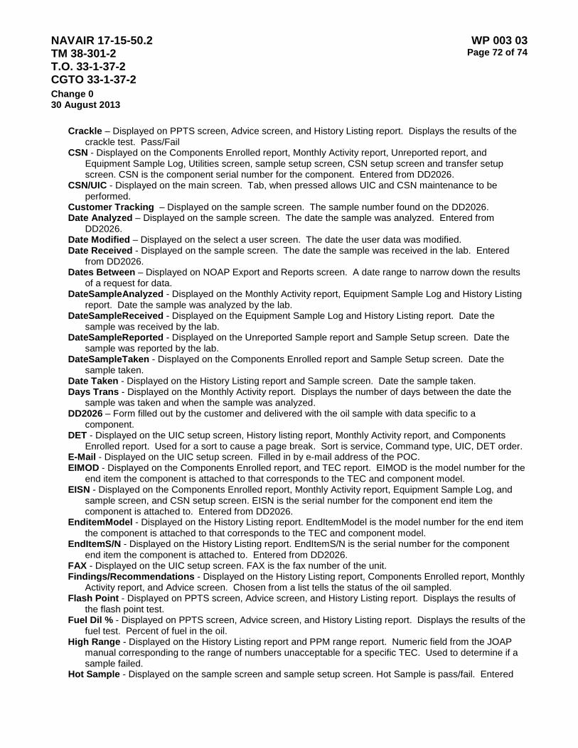
NAVAIR 17-15-50.2 TM 38-301-2 T.O. 33-1-37-2 CGTO 33-1-37-2
WP 003 03 Page 72 of 74
Change 0 30 August 2013
Crackle – Displayed on PPTS screen, Advice screen, and History Listing report. Displays the results of the crackle test. Pass/Fail
CSN - Displayed on the Components Enrolled report, Monthly Activity report, Unreported report, and Equipment Sample Log, Utilities screen, sample setup screen, CSN setup screen and transfer setup screen. CSN is the component serial number for the component. Entered from DD2026.
CSN/UIC - Displayed on the main screen. Tab, when pressed allows UIC and CSN maintenance to be performed.
Customer Tracking – Displayed on the sample screen. The sample number found on the DD2026. Date Analyzed – Displayed on the sample screen. The date the sample was analyzed. Entered from
DD2026. Date Modified – Displayed on the select a user screen. The date the user data was modified. Date Received - Displayed on the sample screen. The date the sample was received in the lab. Entered
from DD2026. Dates Between – Displayed on NOAP Export and Reports screen. A date range to narrow down the results
of a request for data. DateSampleAnalyzed - Displayed on the Monthly Activity report, Equipment Sample Log and History Listing
report. Date the sample was analyzed by the lab. DateSampleReceived - Displayed on the Equipment Sample Log and History Listing report. Date the
sample was received by the lab. DateSampleReported - Displayed on the Unreported Sample report and Sample Setup screen. Date the
sample was reported by the lab. DateSampleTaken - Displayed on the Components Enrolled report and Sample Setup screen. Date the
sample taken. Date Taken - Displayed on the History Listing report and Sample screen. Date the sample taken. Days Trans - Displayed on the Monthly Activity report. Displays the number of days between the date the
sample was taken and when the sample was analyzed. DD2026 – Form filled out by the customer and delivered with the oil sample with data specific to a
component. DET - Displayed on the UIC setup screen, History listing report, Monthly Activity report, and Components
Enrolled report. Used for a sort to cause a page break. Sort is service, Command type, UIC, DET order. E-Mail - Displayed on the UIC setup screen. Filled in by e-mail address of the POC. EIMOD - Displayed on the Components Enrolled report, and TEC report. EIMOD is the model number for the
end item the component is attached to that corresponds to the TEC and component model. EISN - Displayed on the Components Enrolled report, Monthly Activity report, Equipment Sample Log, and
sample screen, and CSN setup screen. EISN is the serial number for the component end item the component is attached to. Entered from DD2026.
EnditemModel - Displayed on the History Listing report. EndItemModel is the model number for the end item the component is attached to that corresponds to the TEC and component model.
EndItemS/N - Displayed on the History Listing report. EndItemS/N is the serial number for the component end item the component is attached to. Entered from DD2026.
FAX - Displayed on the UIC setup screen. FAX is the fax number of the unit. Findings/Recommendations - Displayed on the History Listing report, Components Enrolled report, Monthly
Activity report, and Advice screen. Chosen from a list tells the status of the oil sampled. Flash Point - Displayed on PPTS screen, Advice screen, and History Listing report. Displays the results of
the flash point test. Fuel Dil % - Displayed on PPTS screen, Advice screen, and History Listing report. Displays the results of the
fuel test. Percent of fuel in the oil. High Range - Displayed on the History Listing report and PPM range report. Numeric field from the JOAP
manual corresponding to the range of numbers unacceptable for a specific TEC. Used to determine if a sample failed.
Hot Sample - Displayed on the sample screen and sample setup screen. Hot Sample is pass/fail. Entered
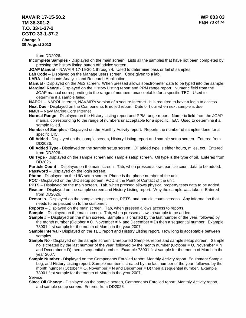
NAVAIR 17-15-50.2 TM 38-301-2 T.O. 33-1-37-2 CGTO 33-1-37-2
WP 003 03 Page 73 of 74
Change 0 30 August 2013
from DD2026. Incomplete Samples - Displayed on the main screen. Lists all the samples that have not been completed by
pressing the history listing button off advice screen. JOAP Manual – NAVAIR 17-15-30 1 through 4. Used to determine pass or fail of samples. Lab Code – Displayed on the Manage users screen. Code given to a lab. LARA - Lubricants Analysis and Research Application Manual - Displayed on the AES screen. When pressed allows spectrometer data to be typed into the sample. Marginal Range - Displayed on the History Listing report and PPM range report. Numeric field from the
JOAP manual corresponding to the range of numbers unacceptable for a specific TEC. Used to determine if a sample failed.
NAPOL – NAPOL Internet, NAVAIR’s version of a secure Internet. It is required to have a login to access. Next Due - Displayed on the Components Enrolled report. Date or hour when next sample is due. NMCI – Navy Marine Corp Internet Normal Range - Displayed on the History Listing report and PPM range report. Numeric field from the JOAP
manual corresponding to the range of numbers unacceptable for a specific TEC. Used to determine if a sample failed.
Number of Samples - Displayed on the Monthly Activity report. Reports the number of samples done for a specific UIC.
Oil Added - Displayed on the sample screen, History Listing report and sample setup screen. Entered from DD2026.
Oil Added Type - Displayed on the sample setup screen. Oil added type is either hours, miles, ect. Entered from DD2026.
Oil Type - Displayed on the sample screen and sample setup screen. Oil type is the type of oil. Entered from DD2026.
Particle Count – Displayed on the main screen. Tab, when pressed allows particle count data to be added. Password – Displayed on the login screen. Phone - Displayed on the UIC setup screen. Phone is the phone number of the unit. POC - Displayed on the UIC setup screen. POC is the Point of Contact of the unit. PPTS – Displayed on the main screen. Tab, when pressed allows physical property tests data to be added. Reason - Displayed on the sample screen and History Listing report. Why the sample was taken. Entered
from DD2026. Remarks - Displayed on the sample setup screen, PPTS, and particle count screens. Any information that
needs to be passed on to the customer. Reports – Displayed on the main screen. Tab, when pressed allows access to reports. Sample – Displayed on the main screen. Tab, when pressed allows a sample to be added. Sample # – Displayed on the main screen. Sample # is created by the last number of the year, followed by
the month number (October = O, November = N and December = D) then a sequential number. Example 73001 first sample for the month of March in the year 2007.
Sample Interval - Displayed on the TEC report and History Listing report. How long is acceptable between samples.
Sample No - Displayed on the sample screen, Unreported Samples report and sample setup screen. Sample no is created by the last number of the year, followed by the month number (October = O, November = N and December = D) then a sequential number. Example 73001 first sample for the month of March in the year 2007.
Sample Number - Displayed on the Components Enrolled report, Monthly Activity report, Equipment Sample Log, and History Listing report. Sample number is created by the last number of the year, followed by the month number (October = O, November = N and December = D) then a sequential number. Example 73001 first sample for the month of March in the year 2007.
Service Since Oil Change - Displayed on the sample screen, Components Enrolled report, Monthly Activity report,
and sample setup screen. Entered from DD2026.

NAVAIR 17-15-50.2 TM 38-301-2 T.O. 33-1-37-2 CGTO 33-1-37-2
WP 003 03 Page 74 of 74
Change 0 30 August 2013
Since Oil Change Type - Displayed on the sample setup screen. Entered from DD2026. Since Overhaul - Displayed on the sample screen, Components Enrolled report, Monthly Activity report, and
sample setup screen. Entered from DD2026. Since Overhaul Type - Displayed on the sample setup screen. Entered from DD2026. SOAP – Squadron Oil Access Program. Used to create DD2026 and keep track of sample results. Standard - Displayed on the Particle Count screen. What standard was used to determine the class? State - Displayed on the UIC setup screen. State is the state of the unit. TAN - Displayed on the History Listing report, Advice screen and PPTS screen. Total Acid number for the
sample. TEC - Displayed on the History Listing report, UIC setup screen, CSN/UIC screen, CSN setup screen, PPM
report and PPM report. Technical equipment code is created to connect specific equipment with their limits.
Trend - Displayed on the History Listing report and Advice screen. Trend is calculated by taking the last two samples and dividing the change in PPM for a specific element over the change in hours times ten.
UIC - Displayed on the History Listing report, Sample screen, Main screen, CSN/UIC screen, CSN setup screen, Components Enrolled report, Monthly Activity report, Equipment Sample Log, Unreported Sample Log, and Transfer Setup screen. UIC is the Unit of Identification. The first character distinguishes the service and 5 digits represent the command.
Unit Name - Displayed on the UIC setup screen, Components Enrolled report, and Monthly Activity report. Unit Name is the name of the unit.
Unit of VISC Measurement – Displayed on the Advice screen and the PPTS screen. Either CP or CS. User Code – Displayed on the Manage Users screen. User Code is entered by the user creating the
account. User Comments – Displayed on the Manage Users screen. User Code is entered by the user creating the
account. User Level – Displayed on the Manage Users screen. The user levels are Application admin – programmer
only, Lab user – access to all except utilities, Read only - access to reports only, Lab Administrator – all User Name – Displayed on the Manage Users screen and Login screen. User Code is entered by the user
creating the account and used in the login process. Utilities – Displayed on the main screen. Tab, when pressed allows access to user accounts, transfer data,
import data, combine samples, backup, purge, sample changes, and move samples. VISC40 C - Displayed on the History Listing report, PPTS screen and Advice screen. VISC40 is the viscosity
at around 40 degrees C. VISC100 C - Displayed on the History Listing report, PPTS screen and Advice screen. VISC100 is the
viscosity at around 100 degrees C. Water - Displayed on the History Listing report, PPTS screen and Advice screen. Water is the amount of
water in the oil. ZIP - Displayed on the UIC setup screen. ZIP is the zip code of the unit.
NAVAIR 17-15-50.2 TM 38-301-2 T.O. 33-1-37-2 CGTO 33-1-37-2
WP 004 00 Page 1 of 2
Change 0 30 August 2013
AIR FORCE OIL ANALYSIS PROGRAM LABORATORIES OPERATING REQUIREMENTS AND PROCEDURES
1. Purpose. The purpose of this work package is to establish the specific configuration requirements and operating procedures for Air Force Oil Analysis Program Laboratories.
2. Applicability. The provisions of this work package apply to all Air Force Oil Analysis Program Laboratories.
3. Work Package Structure. This Work Package is divided into three sections (subordinate work packages):
WP 004 01 – General Laboratory operating procedures and operator training requirements.
WP 004 02 – Laboratory Equipment / Configuration Requirements
WP 004 03 – Oil Analysis Data Recording, Processing, and Warehousing

NAVAIR 17-15-50.2 TM 38-301-2 T.O. 33-1-37-2 CGTO 33-1-37-2
WP 004 00 Page 2 of 2
Change 0 30 August 2013
This Page Intentionally Left Blank

NAVAIR 17-15-50.2 TM 38-301-2 T.O. 33-1-37-2 CGTO 33-1-37-2
WP 004 01 Page 1 of 2
Change 0 30 August 2013
AIR FORCE OIL ANALYSIS PROGRAM - GENERAL LABORATORY OPERATING PROCEDURES
1. Normal samples. Air Force Oil Analysis Laboratories perform only wear metal analysis via rotrode atomic emission spectrometer. Volume II WP 001 00 contains the basic laboratory operating procedures to be followed when performing the task of wear metal analysis on oil samples submitted to a laboratory.
2. Special engine and gearbox lubricant samples. On occasion it may be necessary to have a more detailed analysis of oil samples such as when contamination from jet fuel, hydraulic fluid, water are suspected or there is an apparent loss of viscosity. When such special oil samples become necessary, following instructions apply:
a. Ensure samples are taken properly.
b. Send two 5 dram oil sample bottles. If possible, retain a larger sample bottle for possible further testing requirements. Ensure they are tightly sealed, taped and adequately packed. Include a DD Form 2026 with all pertinent information. Give reason for test(s) and point of contact with DSN number. If analysis requirement is immediate, send by overnight express. If not, send first class to the following address:
AFRL/RQTM ATTN: Lynne Nelson (785-3100) BLDG 490 AREA B 1790 LOOP ROAD N WRIGHT PATTERSON AFB OH 45433-7103 DSN: 785-3100 Commercial: (937) 255-3100
3. Special hydraulic fluid samples. The following instructions apply to suspected problems with hydraulic fluid. Common problems are contamination from particulates, water and other fluids.
a. Refer to MIL-HDBK-3004 for area laboratory locations.
b. If further information is required, a point of contact is WL-POSL at the numbers provided above.
Aerospace Fuels Laboratory (FP2070) AFPA/PTPLA 2430 C Street, Bldg 70, Area B Wright Patterson AFB OH 45433-7632 COMM: (937) 255-2106 DSN: 785-2106

NAVAIR 17-15-50.2 TM 38-301-2 T.O. 33-1-37-2 CGTO 33-1-37-2
WP 004 01 Page 2 of 2
Change 0 30 August 2013
This Page Intentionally Left Blank

NAVAIR 17-15-50.2 TM 38-301-2 T.O. 33-1-37-2 CGTO 33-1-37-2
WP 004 02 Page 1 of 2
Change 0 30 August 2013
AIR FORCE OIL ANALYSIS PROGRAM - LABORATORY EQUIPMENT AND CONFIGURATION REQUIREMENTS
1. Each laboratory shall have a Spectrol M or Spectrol M/N Rotrode Atomic Emission Spectrometer (RAES) and the ancillary equipment and supplies necessary for its operation in accordance with U. S. Air Force T.O. 33B4-2-29-1
2. The lab shall have sufficient bench space to accommodate and operate the oil analysis spectrometer as well as manage the oil sample workload anticipated for the specific laboratory.
3. The oil analysis spectrometer shall be properly ventilated in accordance with Air Force T.O. 33B4-2-29-1

NAVAIR 17-15-50.2 TM 38-301-2 T.O. 33-1-37-2 CGTO 33-1-37-2
WP 004 02 Page 2 of 2
Change 0 30 August 2013
This Page Intentionally Left Blank

NAVAIR 17-15-50.2 TM 38-301-2 T.O. 33-1-37-2 CGTO 33-1-37-2
WP 004 03 Page 1 of 2
Change 0 30 August 2013
AIR FORCE OIL ANALYSIS PROGRAM – DATA RECORDING, PROCESSING, AND WAREHOUSING
NON-AUTOMATED LABORATORY DATA SUBMISSION
1. The following instructions apply to non-automated Air Force laboratories, but may be directed for use by other Service Program Managers for their non-automated laboratories or for automated laboratories experiencing ADP equipment malfunctions, to transmit manually accumulated data into the JOAP Data Base.
2. Laboratories shall use DD Form 2026 as a source document for completing 220+ column detail records. The resulting data will be forwarded to [email protected] the first duty day of EACH week.
a. Follow directions in AETC Software Rev 004 User’s Manual
b. Save Keypunch file as your Base Name and Date (for example: Nellis01Mar2014)
c. Email saved file to [email protected]
3. Control Data. Data in record columns 1 through 24 and 80, as applicable, are designated as control data fields. These columns must be completed on all source documents and all 80 column record cards.
a. JOAP Laboratory Codes. Record columns 1-3.
(1) Designation: JOAP Laboratory Code.
(2) Entry: Alpha/Numeric.
(3) Instructions: JOAP laboratory codes consist of three digit alpha/numeric codes listed in the JOAP Directory.
b. Major Command Codes. Record column 4.
(1) Designation: Major Command.
(2) Entry: Alpha/Numeric.
(3) Instructions: Major Command codes consist of two digit alpha/numeric codes to identify the major command, foreign government, contractor, etc., which owns the unit from which the sample was taken. Non-automated laboratories will use only the last digit of the command code. These codes are listed in Appendix
c. Operating Activity Codes. Record columns 5-10.
(1) Designation: Operating Activity.
(2) Entry: Alpha - Left justified.
(3) Instructions: Enter base location codes in record columns 5-8 (Air Force). Base location codes (also known as geographical location codes or GEOLOC's) consist of four digit alphanumeric codes as reflected on the following Scott AFB hosted website: https://tmds03.scott.af.mil/ap_info.shtml Enter the base location in the "AP NAME" block, click on "Find AP Name Data", and the GEOLOC will be displayed.
d. Equipment/End Item Model Codes. Record columns 11-14.
(1) Designation: Equipment/End Item Model Codes.
(2) Entry: Alpha/Numeric.
(3) Instructions: Equipment model field will reflect codes established in Appendix B to identify the engine type, model and series and the end item mission, design and series for engine samples. Samples

NAVAIR 17-15-50.2 TM 38-301-2 T.O. 33-1-37-2 CGTO 33-1-37-2
WP 004 03 Page 2 of 2
Change 0 30 August 2013
from accessory equipment such as CSD, main transmission, etc., will be reported by entering the first three digits of appropriate end item code and entering the appropriate accessory equipment code as the last digit.
e. Equipment Serial Number. Record columns 15-20.
(1) Designation: Equipment Serial Number.
(2) Entry: Alpha/Numeric - Left justified.
(3) Instructions: Enter last six digits of the equipment serial number from which the oil sample was taken, e.g., engine, transmission, CSD, etc. Dashes and slashes will be excluded.
f. Date. Record columns 21-24.
(1) Designation: Julian Date Sample Taken.
(2) Entry: Numerics.
(3) Instructions: Enter Julian date sample was taken, e.g., YDDD. Y will be the last position of the year and DDD will be the Julian Day.
4. Analytical Sample Record. Analytical sample record is required to report all sample identification data and analytical results. Analytical sample record will contain control data (record columns 1-24 and 80 as applicable) and the following data (see table A-1).

NAVAIR 17-15-50.2 TM 38-301-2 T.O. 33-1-37-2 CGTO 33-1-37-2
WP 005 00 Page 1 of 2
Change 0 30 August 2013
TOTAL ACID NUMBER (TAN) LABORATORY OPERATING PROCEDURES
1. Scope. This method, based on ASTM-D974, determines Total Acid Number (TAN) in petroleum products due to processes such as oxidation.
2. Summary of Method. In the procedure, a weighed amount of lubricant sample is dissolved in a mixture of toluene and isopropyl alcohol and p-Naptholbenzein indicator added. The mixture is then titrated with potassium hydroxide of known normality, until a color, change is observed. The acidity, or Total Acid Number (TAN), of the sample is then calculated based on the milliliters of potassium hydroxide required to neutralize the known of sample.
3. Equipment/Apparatus/Material.
Description Manufacturer Part Number NSN
Jencons Digitrate Pro - 50ml Jencons JENC182-026
Toluene Fisher Scientific TT-T-548 6810-00-281-2002
Isopropyl Alcohol on file O-C-265 6810-00-227-0410
P-Naptholbenzein Fisher Scientific 6810-00-070-7611
0.1N KOH alcoholic KOH Fisher Scientific
erlenmeyer flasks, 250 ml Fisher Scientific S63271
graduated cylinder, 100 ml Fisher Scientific MS35943-7 6640-00-420-0000
apron, laboratory GSA 021-758 8415-00-634-5023
goggles, chemical splash GSA ANSIZ87 1.1989 4240-00-190-6432
gloves, nitrile; medium GSA 8415-01-492-0179
gloves, nitrile; large GSA 8415-01-492-0178
gloves, nitrile; extra large GSA 8415-01-492-0180
kim wipes GSA A-A-1432A 7920-00-721-8884
paper towels GSA 7920-00-823-9773 Notes: For HAZMAT items See Volume II WP HMWS for handling information. The manufacturer's name is provided as an example. Equivalent product obtained from another sources
is acceptable.
4. Operation/Procedures.
a. Prepare titrating solvent. Mix together 500 ml of Toluene, 495 ml of Isopropyl Alcohol and 5 ml of water. Add 0.50 grams of p-Naptholbenzein.
b. Tare an Erlenmeyer flask by placing it on the balance and adjusting the readout to zero.
c. Add sample to the flask until approximately 20 grams of sample has been added. If sample is dark,
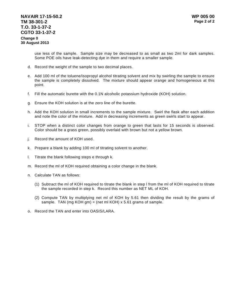
NAVAIR 17-15-50.2 TM 38-301-2 T.O. 33-1-37-2 CGTO 33-1-37-2
WP 005 00 Page 2 of 2
Change 0 30 August 2013
use less of the sample. Sample size may be decreased to as small as two 2ml for dark samples. Some POE oils have leak-detecting dye in them and require a smaller sample.
d. Record the weight of the sample to two decimal places.
e. Add 100 ml of the toluene/isopropyl alcohol titrating solvent and mix by swirling the sample to ensure the sample is completely dissolved. The mixture should appear orange and homogeneous at this point.
f. Fill the automatic burette with the 0.1N alcoholic potassium hydroxide (KOH) solution.
g. Ensure the KOH solution is at the zero line of the burette.
h. Add the KOH solution in small increments to the sample mixture. Swirl the flask after each addition and note the color of the mixture. Add in decreasing increments as green swirls start to appear.
i. STOP when a distinct color changes from orange to green that lasts for 15 seconds is observed. Color should be a grass green, possibly overlaid with brown but not a yellow brown.
j. Record the amount of KOH used.
k. Prepare a blank by adding 100 ml of titrating solvent to another.
l. Titrate the blank following steps e through k.
m. Record the ml of KOH required obtaining a color change in the blank.
n. Calculate TAN as follows:
(1) Subtract the ml of KOH required to titrate the blank in step l from the ml of KOH required to titrate the sample recorded in step k. Record this number as NET ML of KOH.
(2) Compute TAN by multiplying net ml of KOH by 5.61 then dividing the result by the grams of sample. TAN (mg KOH gm) = (net ml KOH) x 5.61 grams of sample.
o. Record the TAN and enter into OASIS/LARA.
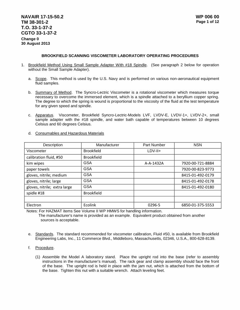
NAVAIR 17-15-50.2 TM 38-301-2 T.O. 33-1-37-2 CGTO 33-1-37-2
WP 006 00 Page 1 of 12
Change 0 30 August 2013
BROOKFIELD SCANNING VISCOMETER LABORATORY OPERATING PROCEDURES
1. Brookfield Method Using Small Sample Adapter With #18 Spindle. (See paragraph 2 below for operation without the Small Sample Adapter).
a. Scope. This method is used by the U.S. Navy and is performed on various non-aeronautical equipment fluid samples.
b. Summary of Method. The Syncro-Lectric Viscometer is a rotational viscometer which measures torque necessary to overcome the immersed element, which is a spindle attached to a beryllium copper spring. The degree to which the spring is wound is proportional to the viscosity of the fluid at the test temperature for any given speed and spindle.
c. Apparatus. Viscometer, Brookfield Syncro-Lectric-Models LVF, LVDV-E, LVDV-1+, LVDV-2+, small sample adapter with the #18 spindle, and water bath capable of temperatures between 10 degrees Celsius and 60 degrees Celsius.
d. Consumables and Hazardous Materials
Description Manufacturer Part Number NSN
Viscometer Brookfield LDV-II+ calibration fluid, #50 Brookfield kim wipes GSA A-A-1432A 7920-00-721-8884 paper towels GSA 7920-00-823-9773 gloves, nitrile; medium GSA 8415-01-492-0179 gloves, nitrile; large GSA 8415-01-492-0178 gloves, nitrile; extra large GSA 8415-01-492-0180 spidle #18 Brookfield
Electron Ecolink 0296-5 6850-01-375-5553 Notes: For HAZMAT items See Volume II WP HMWS for handling information. The manufacturer's name is provided as an example. Equivalent product obtained from another
sources is acceptable.
e. Standards. The standard recommended for viscometer calibration, Fluid #50, is available from Brookfield Engineering Labs, Inc., 11 Commerce Blvd., Middleboro, Massachusetts, 02346, U.S.A., 800-628-8139.
f. Procedure.
(1) Assemble the Model A laboratory stand. Place the upright rod into the base (refer to assembly instructions in the manufacturer’s manual). The rack gear and clamp assembly should face the front of the base. The upright rod is held in place with the jam nut, which is attached from the bottom of the base. Tighten this nut with a suitable wrench. Attach leveling feet.

NAVAIR 17-15-50.2 TM 38-301-2 T.O. 33-1-37-2 CGTO 33-1-37-2
WP 006 00 Page 2 of 12
Change 0 30 August 2013
(2) Insert the mounting handle on the back of the viscometer into the hole on the clamp assembly. Be sure that the clamp screw is loose.
(3) Tighten the clamp screw. Adjust the viscometer to be as close to level as possible while tightening the clamp screw.
(4) Level the viscometer. The level is adjusted using the three leveling screws on the base. Adjust so that the bubble level on top of the viscometer is centered within the circle. Check level periodically during use.
(5) Ensure water bath is filled to the level recommended by the manufacturer.
(6) Connect the tubing from the water bath to the inlet and outlet connectors on the water jacket of the small sample adapter.
(7) Adjust the water bath temperature.
g. Instrument Start-Up. (LVDV-E, LVDV-1+, LVDV-2+)
NOTE
Before a reading can be taken, the viscometer must be auto-zeroed. This action is performed each time the power switch is turned on. The display window on the viscometer displays a guide through the procedure.
(1) Turn the power switch (located on the rear panel) to the ON position. This will result in the following screen display:
BROOKFIELD
RV VISCOMETER
The model type will be displayed in the upper right-hand corner of the screen (DV-1+, DV-2+, etc.).
After a few seconds, the following screen appears:
BROOKFIELD
VERSION 5.0
(2) After a short time the viscometer will instruct you to remove the spindle and that any key be pressed. The viscometer will begin to auto-zero itself.
NOTE
Ensure that the viscometer is level before initiating auto-zero.
(3) After the viscometer has completed its auto-zeroing, follow the directions to replace the spindle and press any key. Pressing any key at this point will result in the display of the default screen.
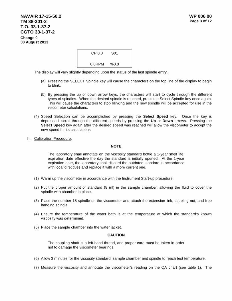
NAVAIR 17-15-50.2 TM 38-301-2 T.O. 33-1-37-2 CGTO 33-1-37-2
WP 006 00 Page 3 of 12
Change 0 30 August 2013
CP 0.0 S01
0.0RPM %0.0
The display will vary slightly depending upon the status of the last spindle entry.
(a) Pressing the SELECT Spindle key will cause the characters on the top line of the display to begin to blink.
(b) By pressing the up or down arrow keys, the characters will start to cycle through the different types of spindles. When the desired spindle is reached, press the Select Spindle key once again. This will cause the characters to stop blinking and the new spindle will be accepted for use in the viscometer calculations.
(4) Speed Selection can be accomplished by pressing the Select Speed key. Once the key is depressed, scroll through the different speeds by pressing the Up or Down arrows. Pressing the Select Speed key again after the desired speed was reached will allow the viscometer to accept the new speed for its calculations.
h. Calibration Procedure.
NOTE
The laboratory shall annotate on the viscosity standard bottle a 1-year shelf life, expiration date effective the day the standard is initially opened. At the 1-year expiration date, the laboratory shall discard the outdated standard in accordance with local directives and replace it with a more current one.
(1) Warm up the viscometer in accordance with the Instrument Start-up procedure.
(2) Put the proper amount of standard (8 ml) in the sample chamber, allowing the fluid to cover the spindle with chamber in place.
(3) Place the number 18 spindle on the viscometer and attach the extension link, coupling nut, and free hanging spindle.
(4) Ensure the temperature of the water bath is at the temperature at which the standard’s known viscosity was determined.
(5) Place the sample chamber into the water jacket.
CAUTION
The coupling shaft is a left-hand thread, and proper care must be taken in order not to damage the viscometer bearings.
(6) Allow 3 minutes for the viscosity standard, sample chamber and spindle to reach test temperature.
(7) Measure the viscosity and annotate the viscometer’s reading on the QA chart (see table 1). The
NAVAIR 17-15-50.2 TM 38-301-2 T.O. 33-1-37-2 CGTO 33-1-37-2
WP 006 00 Page 4 of 12
Change 0 30 August 2013
factor of the spindle and fluid accuracy determines the total tolerance of the fluid. Table 2 provides the various factors for spindles.
NOTE
Instrument tolerance is equal to spindle factor. If the spindle factor is 10, then the viscometer’s tolerance will be 10.
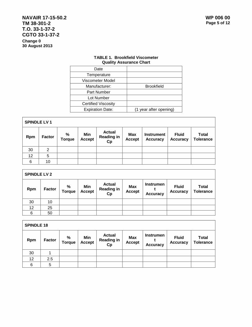
NAVAIR 17-15-50.2 TM 38-301-2 T.O. 33-1-37-2 CGTO 33-1-37-2
WP 006 00 Page 5 of 12
Change 0 30 August 2013
TABLE 1. Brookfield Viscometer Quality Assurance Chart
Date Temperature
Viscometer Model Manufacturer: Brookfield Part Number Lot Number
Certified Viscosity Expiration Date: (1 year after opening)
SPINDLE LV 1
Rpm Factor % Torque
Min Accept
Actual Reading in
Cp Max
Accept Instrument Accuracy
Fluid Accuracy
Total Tolerance
30 2 12 5 6 10
SPINDLE LV 2
Rpm Factor % Torque
Min Accept
Actual Reading in
Cp
Max Accept
Instrument
Accuracy
Fluid Accuracy
Total Tolerance
30 10 12 25 6 50
SPINDLE 18
Rpm Factor % Torque
Min Accept
Actual Reading in
Cp
Max Accept
Instrument
Accuracy
Fluid Accuracy
Total Tolerance
30 1 12 2.5 6 5
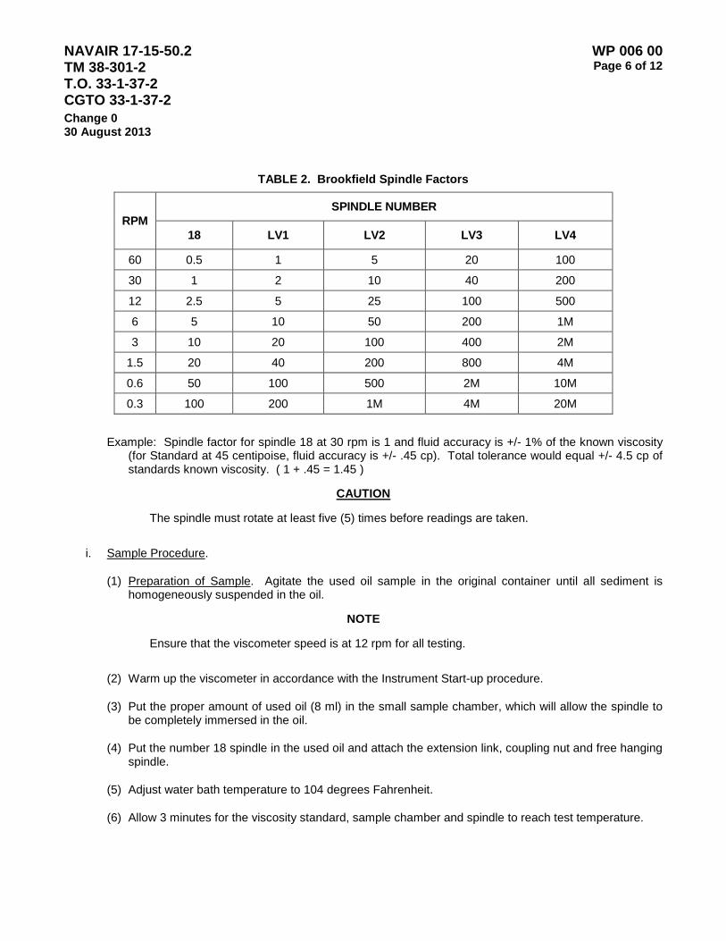
NAVAIR 17-15-50.2 TM 38-301-2 T.O. 33-1-37-2 CGTO 33-1-37-2
WP 006 00 Page 6 of 12
Change 0 30 August 2013
TABLE 2. Brookfield Spindle Factors
RPM SPINDLE NUMBER
18 LV1 LV2 LV3 LV4
60 0.5 1 5 20 100
30 1 2 10 40 200
12 2.5 5 25 100 500
6 5 10 50 200 1M
3 10 20 100 400 2M
1.5 20 40 200 800 4M
0.6 50 100 500 2M 10M
0.3 100 200 1M 4M 20M
Example: Spindle factor for spindle 18 at 30 rpm is 1 and fluid accuracy is +/- 1% of the known viscosity (for Standard at 45 centipoise, fluid accuracy is +/- .45 cp). Total tolerance would equal +/- 4.5 cp of standards known viscosity. ( 1 + .45 = 1.45 )
CAUTION
The spindle must rotate at least five (5) times before readings are taken.
i. Sample Procedure.
(1) Preparation of Sample. Agitate the used oil sample in the original container until all sediment is homogeneously suspended in the oil.
NOTE
Ensure that the viscometer speed is at 12 rpm for all testing.
(2) Warm up the viscometer in accordance with the Instrument Start-up procedure.
(3) Put the proper amount of used oil (8 ml) in the small sample chamber, which will allow the spindle to be completely immersed in the oil.
(4) Put the number 18 spindle in the used oil and attach the extension link, coupling nut and free hanging spindle.
(5) Adjust water bath temperature to 104 degrees Fahrenheit.
(6) Allow 3 minutes for the viscosity standard, sample chamber and spindle to reach test temperature.
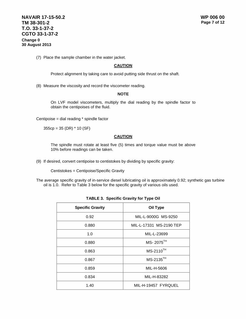
NAVAIR 17-15-50.2 TM 38-301-2 T.O. 33-1-37-2 CGTO 33-1-37-2
WP 006 00 Page 7 of 12
Change 0 30 August 2013
(7) Place the sample chamber in the water jacket.
CAUTION
Protect alignment by taking care to avoid putting side thrust on the shaft.
(8) Measure the viscosity and record the viscometer reading.
NOTE
On LVF model viscometers, multiply the dial reading by the spindle factor to obtain the centipoises of the fluid.
Centipoise = dial reading * spindle factor
355cp = 35 (DR) * 10 (SF)
CAUTION
The spindle must rotate at least five (5) times and torque value must be above 10% before readings can be taken.
(9) If desired, convert centipoise to centistokes by dividing by specific gravity:
Centistokes = Centipoise/Specific Gravity
The average specific gravity of in-service diesel lubricating oil is approximately 0.92; synthetic gas turbine oil is 1.0. Refer to Table 3 below for the specific gravity of various oils used.
TABLE 3. Specific Gravity for Type Oil
Specific Gravity Oil Type
0.92 MIL-L-9000G MS-9250
0.880 MIL-L-17331 MS-2190 TEP
1.0 MIL-L-23699
0.880 MS- 2075TH
0.863 MS-2110TH
0.867 MS-2135TH
0.859 MIL-H-5606
0.834 MIL-H-83282
1.40 MIL-H-19457 FYRQUEL

NAVAIR 17-15-50.2 TM 38-301-2 T.O. 33-1-37-2 CGTO 33-1-37-2
WP 006 00 Page 8 of 12
Change 0 30 August 2013
j. Cleaning. Clean the small sample chamber with cleaning solvent and wipe dry with a non-abrasive cloth.
CAUTION
Electron should be used with adequate ventilation. Prolonged breathing of vapors should be avoided. The solvent should not be used near open flame or heat, as the products of decomposition are toxic and very irritating.
NOTE
The black insulating bottom of the sample chamber should not be exposed to strong solvents such as methanol, toluene, ammonia, and 111-trichloroethylene. Do not totally immerse the chamber in any cleaning solution. Improper cleaning may result in separation of the black insulation from the chamber.
2. Brookfield Method without Small Sample Adapter.
a. Scope. This method is used by the U.S. Navy and is performed on various non-aeronautical equipment fluid samples.
b. Summary of Method. The Syncro-Lectric Viscometer is a rotational viscometer which measures the torque necessary to overcome the immersed element, which is a spindle attached to a beryllium copper spring. The degree to which the spring is wound is proportional to the viscosity of the fluid at the test temperature for any given speed and spindle.
c. Apparatus. Viscometer, Brookfield Syncro-Lectric-Models LVF, LVDV-E, LVDV-1+, LVDV-2+, 100 ml beaker, oven and a digital thermometer capable of temperature ranges between -40 to 250 degrees Fahrenheit.
d. Standards. The standard recommended for viscometer calibration, Fluid #50, is available from Brookfield Engineering Labs, Inc., 11 Commerce Blvd., Middleboro, Massachusetts, 02346, U.S.A., 800-628-8139.
e. Procedure.
(1) To assemble the Model A laboratory stand, place the upright rod into the base (refer to assembly instructions in manufacturer’s manual). The rack gear and clamp assembly should face the front of the base. The upright rod is held in place with the jam nut, which is attached from the bottom of the base. Tighten this nut with a suitable wrench. Attach the leveling feet.
(2) Insert the mounting handle on the back of the viscometer into the hole on the clamp assembly. Be sure that the clamp screw is loose.
(3) Tighten the clamp screw. Adjust the viscometer to be as close to level as possible while tightening the clamp screw.
(4) Level the viscometer. The level is adjusted using the three leveling screws on the base. Adjust so that the bubble level on top of the viscometer is centered within the circle. Check level periodically during use.
NAVAIR 17-15-50.2 TM 38-301-2 T.O. 33-1-37-2 CGTO 33-1-37-2
WP 006 00 Page 9 of 12
Change 0 30 August 2013
NOTE
Before a reading can be taken, the viscometer must be auto-zeroed. This action is performed each time the power switch is turned on. The display window on the viscometer displays a guide for the procedure. Refer to Paragraph 1.f for complete instructions.
f. Calibration Procedure.
NOTE
The laboratory shall annotate on the viscosity standard bottle a 1-year shelf life, expiration date effective the day the standard is initially opened. At the 1-year expiration date, the laboratory shall discard the outdated standard in accordance with local regulations and replace it with a more current one.
(1) Warm up the viscometer in accordance with the Instrument Start-up procedure.
(2) Place the number 1 or 2 spindle on the viscometer. In order to use the smaller beaker, the spindle guard cannot be used. Take care not to bump the spindle.
CAUTION
The coupling shaft is a left-hand thread, and proper care must be taken in order not to damage the viscometer bearings.
(3) Put the proper amount of standard in a 100 ml beaker allowing the fluid to reach the groove imbedded on the spindle.
(4) Allow the fluid to reach the temperature at which the standard’s known viscosity was determined.
(5) Measure the viscosity and annotate the viscometer’s reading on the QA chart (Table 1). The factor of the spindle and fluid accuracy determines the total tolerance of the fluid. Table 2 shows the various factors for spindles. Example: Spindle factor for spindle 18 at 30 rpm is 1 and fluid accuracy is +/- 1% of the known viscosity (for Standard at 45 centipoise, fluid accuracy is +/- .45 cp). Total tolerance would equal +/- 5.5 cp of standards known viscosity ( 1 + .45 = 1.45 ).
CAUTION
The spindle must rotate at least five (5) times before readings are taken.
g. Sample Procedure.
(1) Warm up the viscometer in accordance with the Instrument Start-up procedure.
(2) Place the number 1 or 2 spindle on the viscometer. To determine the proper spindle, a known range of viscosity should be determined for the fluid (see table 4).

NAVAIR 17-15-50.2 TM 38-301-2 T.O. 33-1-37-2 CGTO 33-1-37-2
WP 006 00 Page 10 of 12
Change 0 30 August 2013
NOTE
Ensure the spindle speed is set at 60 RPM.
TABLE 4. Spindle/Range Information
SPINDLE RANGE
LV-1 15-20K LV-2 50-100K
SCV4-18 1.2-30K
CAUTION
The coupling shaft is a left-hand thread, and proper care must be taken in order not to damage the viscometer bearings.
(3) Put the proper amount of used oil with in the container, allowing the fluid to reach the groove imbedded on the spindle.
(4) Place the sample in the oven and allow the fluid to reach 104 degrees Fahrenheit.
(5) Measure the viscosity and annotate the viscometer’s reading.
CAUTION
The spindle must rotate at least five (5) times before readings are taken.
(6) Convert centipoise to centistokes by dividing by specific gravity, and record the viscosity of the sample.
NOTE
On LVF model viscometers, multiply the dial reading by the spindle factor to obtain the centipoises of the fluid.
Centipoise = dial reading * spindle factor
355cp = 35 (DR) * 10 (SF)
Centistoke= Centipoise/Specific Gravity
The average specific gravity of in-service diesel lubricating oil is approximately 0.92; synthetic gas turbine oil is 1.0. Refer to Table 3 for the specific gravity of various oils used.
h. Cleaning. Clean the spindle with cleaning solvent and wipe dry with a non-abrasive cloth.
NAVAIR 17-15-50.2 TM 38-301-2 T.O. 33-1-37-2 CGTO 33-1-37-2
WP 006 00 Page 11 of 12
Change 0 30 August 2013
CAUTION
Electron should be used with adequate ventilation. Prolonged breathing of vapors should be avoided. The solvent should not be used near open flame or heat, as the products of decomposition are toxic and very irritating.

NAVAIR 17-15-50.2 TM 38-301-2 T.O. 33-1-37-2 CGTO 33-1-37-2
WP 006 00 Page 12 of 12
Change 0 30 August 2013
This Page Intentionally Left Blank

NAVAIR 17-15-50.2 TM 38-301-2 T.O. 33-1-37-2 CGTO 33-1-37-2
WP 007 00 Page 1 of 4
Change 0 30 August 2013
CAMBRIDGE VISCOMETER LABORATORY OPERATING PROCEDURES
1. Scope. This method is to be used for analysis of lubricating oils with viscosity in the range of 12 to 250 centistokes (10 to 200 centipoise) at a preset temperature.
2. Summary of Method.
3. Equipment/Apparatus/Materials.
Description Manufacturer Part Number NSN
Viscolab 3000 Viscometer Cambridge Applied Systems
Viscolab piston Cambridge Applied Systems Viscosity standard Cambridge Applied Systems P/N S60s Isopropyl Alcohol Fischer Scientific2 Foam tip swabs Paper towels GSA 7920-00-823-9773 Forceps Chem-wipes or other lint free wipes
GSA A-A-1432A 7920-00-721-8884
forceps plastic pipettes Samco H56822533 Notes: For HAZMAT items See Volume II WP HMWS for handling information. The manufacturer's name is provided as an example. Equivalent product obtained from another sources
is acceptable.
4. Applicable Standards.
5. Operation/Procedure.
a. Instrument Setup.
(1) Unpack the viscometer. The package should contain a control unit, sensor, instruction book, fan, printer, swabs, plastic pipettes, forceps and a piston.
NOTE
The piston is precision machined to mate with the chamber. They are a matched pair. The piston must not be scratched or damaged in any way. Keep the piston in its plastic case when not in use.
(2) Place the control unit and sensor unit on the table.

NAVAIR 17-15-50.2 TM 38-301-2 T.O. 33-1-37-2 CGTO 33-1-37-2
WP 007 00 Page 2 of 4
Change 0 30 August 2013
(3) Connect the sensor connector to the back of the control unit. The large green connector attaches to the sensor connector seen at the upper right when facing the back of the control unit. The small green connector attaches to the time Proportional control into the small green connector in the center bottom of the unit. Plug the serial cable for the printer into the RS232 connector adjacent to the sensor connection. Connect the power cord and plug into a 12V or 240V/60 Hz outlet. Plug in the printer power cord.
(4) Remove the Cap and thermal jacket from the sensor assembly unless viscosity measurement will be performed at a temperature higher than 60 degrees C.
(5) Position the fan 7” to 12” from the sensor assembly. Adjust the fan position as necessary to maintain the required temperature setting.
(6) Ensure the measurement chamber is clean and dry.
b. Standardization/Calibration.
(1) Calibration. Calibration is performed by the OEM. Calibration is performed if the standardization fails and is also recommended yearly.
(2) The instrument must be checked with a viscosity standard prior to first use of the day.
(a) Turn on the Viscolab 3000 using the power switch on the right hand side of the control module. Turn on the printer using the power switch located on the left side of the printer, and the fan if you will be operating the viscometer at temperatures of 60 °C or less.
(b) After a few seconds the main menu will appear. The first entry in the menu is OPERATE. Select the TEMPERATURE CONTROL option by using the arrow keys to move the “select arrow” to the option. Press the ENTER button to open the TEMPERATURE CONTROL menu.
(c) Select HEATER ON and set the temperature to 40 degrees C. If the temperature set point is correct press ENTER twice. (If a change in temperature id needed use the ESCAPE and ENTER buttons and left and right buttons respectively. The arrow buttons will change the numerals.)
(d) Once a temperature is selected and the heater is on, the instrument will display “Sensor is standby.” At this point allow the instrument temperature time to reach the set point and stabilize until the uncertainty in the temperature reading is less than or equal to +/- 0.1 °C. (For example, before moving on to the next step a 40 °C set point should have a reading of 40.0 °C +/- 0.1 °.)
(e) After the instrument temperature has stabilized, fill the bottom chamber (narrow portion) of the sample probe with the viscosity standard using a disposable dropper. Approximately 2 mL are needed.
(f) Use forceps to carefully insert the piston into the sample chamber with the conical side facing down. There should be no resistance. Push the piston just below the level of the sample, and leave it in the sample chamber.
(g) Place the cap on top of the sample probe.
NAVAIR 17-15-50.2 TM 38-301-2 T.O. 33-1-37-2 CGTO 33-1-37-2
WP 007 00 Page 3 of 4
Change 0 30 August 2013
(h) Select OPERATE on the main menu and press ENTER. Select ANALYZE & REPORT and press ENTER again. (This option provides time for the sample temperature to equilibrate, and collect an appropriate number of data points. Total time for this operation is typically 20-30 minutes.)
(i) When the instrument has finished, the words “Measurement Complete” will appear at the top of the screen along with the data for the sample. The data should also automatically printout on the printer.
(j) Press ENTER to return to the OPERATE menu.
(k) Select the REMOVE PISTON option and press ENTER. The instrument will return to standby mode. Carefully remove the piston using locking forceps. Little force should be required. Clean the piston using Kimwipes and isopropanol.
(l) Press ENTER when done.
(m) Return to the OPERATE menu, select the PURGE SENSOR option, and press ENTER. The instrument will display purge sensor on the screen. At this point, dump the sample out of the sensor into a waste beaker and wash the sensor with isopropanol. Use the swabs provided and more isopropanol if necessary to clean the lower portion of the sample chamber. Use Kimwipes to clean the upper portion as needed.
(n) If the viscosity standard is within _____% of the value indicated on the bottle proceed with sample measurement.
(3) Processing Samples.
(a) Press the down arrow until the choice for “Units of Measure” can be selected. Select the Units of measure and set the viscosity units to Centistokes. The instrument will prompt for a density entry. Use table __________ and enter the density of the fluid being tested.
TABLE____ Fluid Densities
(b) Select the TEMPERATURE CONTROL option by using the arrow keys to move the “select arrow” to the option. Press the ENTER button to open the TEMPERATURE CONTROL menu.
(c) Select HEATER ON and set the temperature to 40 degrees C. If the temperature set point is correct press ENTER twice. (If a change in temperature is needed use the ESCAPE and ENTER buttons and left and right buttons respectively. The arrow buttons will change the numerals.)
(d) Once a temperature is selected and the heater is on, the instrument will display “Sensor is standby.” At this point allow the instrument temperature time to reach the set point and stabilize until the uncertainty in the temperature reading is less than or equal to +/- 0.1 °C. (For example, before moving on to the next step a 40 °C set point should have a reading of 40.0 °C +/- 0.1 °.)
(e) After the instrument temperature has stabilized, fill the bottom chamber (narrow portion) of the sample probe with the viscosity standard using a disposable dropper. Approximately 2 mL are needed.
NAVAIR 17-15-50.2 TM 38-301-2 T.O. 33-1-37-2 CGTO 33-1-37-2
WP 007 00 Page 4 of 4
Change 0 30 August 2013
CAUTION
Ensure that the sample is free from particulate matter and bubbles.
(f) Use forceps to carefully insert the piston into the sample chamber with the conical side facing down. There should be no resistance. Push the piston just below the level of the sample, and leave it in the sample chamber.
(g) Place the cap on top of the sample probe.
(h) Select OPERATE on the main menu and press ENTER. Select ANALYZE & REPORT and press ENTER again. (This option provides time for the sample temperature to equilibrate, and collect an appropriate number of data points. Total time for this operation is typically 20-30 minutes.)
(i) When the instrument has finished, the words “Measurement Complete” will appear at the top of the screen along with the data for the sample. The data should also automatically printout on the printer.
(j) Press ENTER to return to the OPERATE menu.
(k) Select the REMOVE PISTON option and press ENTER. The instrument will return to standby mode. Carefully remove the piston using locking forceps. Little force should be required. Clean the piston using Kimwipes and isopropanol.
(l) Press ENTER when done.
(m) Return to the OPERATE menu, select the PURGE SENSOR option, and press ENTER. The instrument will display purge sensor on the screen. At this point, dump the sample out of the sensor into a waste beaker and wash the sensor with isopropanol. Use the swabs provided and more isopropanol if necessary to clean the lower portion of the sample chamber. Use Kimwipes to clean the upper portion as needed.

NAVAIR 17-15-50.2 TM 38-301-2 T.O. 33-1-37-2 CGTO 33-1-37-2
WP 008 00 Page 1 of 2
Change 0 30 August 2013
CRACKLE TEST
1. Scope of Test. The crackle test is a simple test used to identify the presence of free and emulsified water that is suspended in oil. Water contamination refers to the presence of free water in used lubricating oils, and is usually performed on non-aeronautical samples. The crackle test indicates whether water is present. If the exact amount of water is desired, the Karl Fischer test for water shall be conducted.
2. Equipment/Apparatus/Materials.
Description Manufacturer Part Number NSN
no chemicals required for test
kim wipes GSA A-A-1432A 7920-00-721-8884
paper towels GSA 7920-00-823-9773
hot plate Thermo Scientific 1 6640-01-125-3765
oil dropper Samco H56822533
thermometer PTC Instruments 1 Model 572FM
goggles, chemical splash ANSIZ87 1.1989 4240-00-190-6432
gloves, nitrile; medium GSA 8415-01-492-0179
gloves, nitrile; large GSA 8415-01-492-0178
gloves, nitrile; extra large GSA 8415-01-492-0180 Notes: 1The manufacturer's name is provided as an example. Equivalent product obtained from another sources
is acceptable.
3. Applicable Standards. None
4. Summary of Method. Water held in suspension by emulsifiers becomes audible (crackles) and visible as bubbles and steam when drops of oil are place on a heated surface of 300 deg F.
a. The method is non-quantitative.
b. Hot plate temperatures above 300 degrees F induce rapid scintillation that may be undetectable.
c. The method does not measure the presence of chemically dissolved water.
5. Safety Considerations.
a. Protective eyewear is suggested.
b. Long sleeves are suggested.
c. Testing must be performed in a well-ventilated area or inside of a fume hood.
NAVAIR 17-15-50.2 TM 38-301-2 T.O. 33-1-37-2 CGTO 33-1-37-2
WP 008 00 Page 2 of 2
Change 0 30 August 2013
WARNING
Persons performing test must wear protective goggles and clothing and avoid direct contact with hot plate surface.
6. Interferences.
a. Refrigerants and other low boiling-point suspensions may interfere.
b. Different base stocks, viscosities, and additives will exhibit varying results.
c. Certain synthetics, such as esters, may not produce scintillation.
7. Operation/Procedures.
a. Achieve surface temperature on a hot plate of 300 degrees F (135 degrees C). Always use the same temperature.
b. Violently agitate oil sample to achieve homogenous suspension of water in oil.
c. Using a clean dropper, place a drop of oil on the hot plate.
d. Observe the drop of oil:
(1) Record the reaction as positive (1), meaning bubbles were present; or negative (0), meaning bubbles were not present.
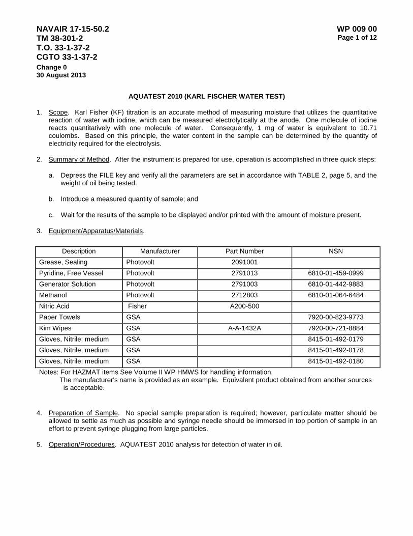
NAVAIR 17-15-50.2 TM 38-301-2 T.O. 33-1-37-2 CGTO 33-1-37-2
WP 009 00 Page 1 of 12
Change 0 30 August 2013
AQUATEST 2010 (KARL FISCHER WATER TEST)
1. Scope. Karl Fisher (KF) titration is an accurate method of measuring moisture that utilizes the quantitative reaction of water with iodine, which can be measured electrolytically at the anode. One molecule of iodine reacts quantitatively with one molecule of water. Consequently, 1 mg of water is equivalent to 10.71 coulombs. Based on this principle, the water content in the sample can be determined by the quantity of electricity required for the electrolysis.
2. Summary of Method. After the instrument is prepared for use, operation is accomplished in three quick steps:
a. Depress the FILE key and verify all the parameters are set in accordance with TABLE 2, page 5, and the weight of oil being tested.
b. Introduce a measured quantity of sample; and
c. Wait for the results of the sample to be displayed and/or printed with the amount of moisture present.
3. Equipment/Apparatus/Materials.
Description Manufacturer Part Number NSN
Grease, Sealing Photovolt 2091001 Pyridine, Free Vessel Photovolt 2791013 6810-01-459-0999 Generator Solution Photovolt 2791003 6810-01-442-9883 Methanol Photovolt 2712803 6810-01-064-6484 Nitric Acid Fisher A200-500 Paper Towels GSA 7920-00-823-9773 Kim Wipes GSA A-A-1432A 7920-00-721-8884 Gloves, Nitrile; medium GSA 8415-01-492-0179 Gloves, Nitrile; medium GSA 8415-01-492-0178 Gloves, Nitrile; medium GSA 8415-01-492-0180 Notes: For HAZMAT items See Volume II WP HMWS for handling information. The manufacturer's name is provided as an example. Equivalent product obtained from another sources
is acceptable.
4. Preparation of Sample. No special sample preparation is required; however, particulate matter should be allowed to settle as much as possible and syringe needle should be immersed in top portion of sample in an effort to prevent syringe plugging from large particles.
5. Operation/Procedures. AQUATEST 2010 analysis for detection of water in oil.

NAVAIR 17-15-50.2 TM 38-301-2 T.O. 33-1-37-2 CGTO 33-1-37-2
WP 009 00 Page 2 of 12
Change 0 30 August 2013
a. Proper Use.
(1) Do not use this product for any purpose other than for which it was intended.
(2) When storing or moving the instruments refer to operating manual for proper storing of this equipment.
(3) Use only those accessories recommended by the manufacturer in order to avoid risk of fire, shock, or other hazards.
(4) Unplug all equipment exposed to rain, moisture, or strong impact and have the instrument inspected by qualified service technician before use.
(5) Disconnect all equipment from the line power source during a lightning storm or before leaving unused for extended periods of time.
(6) Unplug all equipment before cleaning. Then use a clean, dry, chemically untreated cotton cloth to wipe the unit. Use no cleaning fluids, aerosols or forced air that could over spray or soak into the unit and cause electrical shock.
b. Setting Up for Operation.
(1) The AQUATEST 2010 has Type T line voltage fuses in series with the power supply. These fuses are located on the rear panel. To replace the fuses, unplug the line cord and remove the fuse cover from the power-input module. Remove the fuse/selector cover. Do not remove or change the setting of the voltage selector. Pull out each fuse drawer and replace both fuses with two of the identical rating. Always change both fuses.
IMPORTANT NOTE
The AQUATEST 2010 is shipped without fuses installed. Prior to applying power, verify that the appropriate fuses are installed and that the voltage selection switch is set to the correct voltage.
WARNING
For protection against fire, replace both fuses with two of identical rating. Refer to TABLE 1 for proper fuse ratings for the selected voltage.
TABLE 1. Fuse Ratings for Selected Voltage
Voltage Rating Fuse Description
100/115 Type T, 0.4 amp. 250V, Slow Blow UL Listed 220/240 Type T, 0.2 amp. 250V, Slow Blow IEC Approved
(2) The AQUATEST 2010 is designed to operate at nominal line voltages of 100/115/220/240 VAC, depending upon the setting of the voltage selection switch located on the back of the instrument. The
NAVAIR 17-15-50.2 TM 38-301-2 T.O. 33-1-37-2 CGTO 33-1-37-2
WP 009 00 Page 3 of 12
Change 0 30 August 2013
red notch on the voltage selection switch indicates the selected operating voltage. To change the voltage, first unplug the line cord. Open the fuse drawer and check the fuse ratings compared to the desired voltage setting. Change the fuses if necessary. If the voltage is being changed from 110/115V to 220/240V or 220/240V to 110/115V, the fuses must be changed. Both fuses must be replaced together.
(3) Using a flat bladed screwdriver, move the rotary dial so that the new voltage is indicated on the switch.
c. Assembling the Titration Cell. The titration cell for the AQUATEST 2010 consists of a titration vessel, generator cartridge, sensing electrode, injection port, vent tube, stir bar, and gas port stopper. The titration cell is assembled as follows:
IMPORTANT NOTE
Before assembling the titration cell, all part must be properly lubricated with Photo volt Sealant to prevent seizing of parts to the generator vessel.
(1) Place the stir bar into the vessel.
(2) Lubricate the ground glass portion of the sensing electrode and insert into the proper port on vessel.
(3) Place a septum inside the 2-pice injection port assembly and gently tighten the threaded portions.
(4) Lubricate the ground glass portion of the gas port stopper and the rounded sides of the sample injection port.
(5) The injection port can occupy one of two positions on the titration vessel. Select the preferred position for the injection port and insert the stopper into the remaining port.
(6) Fill the vent tube with silica gel desiccant. A plug of glass wool may be used under and over the desiccant. Lubricate the slotted stopper and the ground glass joint at the bottom of the tube. Insert the vent tube into the proper port on the vessel. Insert the slotted stopper into the vent tube.
NOTE
The silica gel desiccant must be replaced periodically. If the blue indicating beads are no longer blue through more than 50 percent of the tube, replace the desiccant.
(7) Remove the generator cartridge from the packing. Remove the foam insert. Lubricate the solid stopper and ground glass joint on the body of the generator. Assemble the pieces and insert into the proper port on the vessel.
WARNING
Proper personal protective equipment (PPE) should be used with all hazardous chemicals. Refer to the MSDS for the hazards involved with each chemical being used.
NAVAIR 17-15-50.2 TM 38-301-2 T.O. 33-1-37-2 CGTO 33-1-37-2
WP 009 00 Page 4 of 12
Change 0 30 August 2013
d. Filling the Vessel with KF Reagents. Selection of reagents is an important factor in the overall performance of a coulometric titration. Photovolt provides reagents designed to provide optimal performance in the analysis of the wide variety of materials. Photovolt Pyridine Free KF Reagent is the most popular reagent currently in use. Pyridine is replaced by a proprietary amine, which has a reduced odor and toxicity compared to pyridine.
WARNING
Dispose of Karl Fischer reagents, solvents and cleaning solutions in a proper manner. Refer to the MSDS sheets for the chemicals to identify chemical hazards. Follow all applicable regulations regarding disposal of chemical waste.
(1) Remove the stopper from the gas tube port of the vessel and pour approximately 150 ml of Photovolt Coulometric KF vessel solution into the cell using a large polyethylene funnel supplied. Replace the stopper.
NOTE
Take care to avoid getting water into the vessel when filling with the reagents. Make sure the vessel is free from water.
(2) Remove the stopper from the top of the generator.
(3) Carefully crack the top off one 5 ml ampoule of Photovolt Coulometric KF generator solution.
(4) Pour the full contents of the ampoule into the generator using the small polyethylene funnel supplied with the reagent.
(5) Replace the stopper.
NOTE
For best results, maintain the level of the solution in the generator well below the level of the solution in the vessel.
(6) Set the slide lever on the left side of the instrument approximately half way through its range to achieve a moderate rate of stirring. Avoid setting the lever to high to reduce “tumbling”. This action could damage the electrode.
(7) When facing the AQUATEST 2010, connect the sensing electrode to the BNC connector on the right denoted by the letter D for detector. Connect the generator to the BNC connector on the left denoted by the letter G for generator.
e. Achieving Set Point. Generally, after filling the vessel with solution, the AQUATEST 2010 will need to be equilibrated before beginning analysis of samples or standards. This process is referred to as “bringing to set point.” In most cases, the AQUATEST 2010 will come to set point in less than 10 minutes. The exact amount of time required for the process, generally depends upon how “wet” the vessel solution is during filling. A very small amount of water present in the vessel, before the addition of reagent, can add a great deal of time to the process. For this reason, it is best to ensure that the components of the vessel are

NAVAIR 17-15-50.2 TM 38-301-2 T.O. 33-1-37-2 CGTO 33-1-37-2
WP 009 00 Page 5 of 12
Change 0 30 August 2013
reasonably free of moisture before assemble.
WARNING
The AQUATEST 2010 sensing electrode can be damaged by exposure to high heat. DO NOT place the sensing electrode in an oven.
(1) Turn on the power switch. The following message should be displayed:
###### S T B Y
Where the # # are present indicates potential.
NOTE
If the potential shows a negative value, this indicates that the vessel solution contains a large amount of free iodine. Excess iodine may be present in the vessel solution as a result of the reagent manufacturing process. If this is observed, add approximately 2 uL of pure water until the potential becomes positive.
(2) Press the [STANDBY] key. The display indicates the titration rate (ug H2O/sec), current demand sign (*), status and total moisture, for example:
12 . 5 * WET 765 .8 ug
After titration of residual moisture from filling the vessel with the solutions, the titration stops, the beeper will sound three times and the following will be displayed:
END
After a few seconds and if the background is above 0.1 ug H2O/sec., the display will read:
RDY
If the background is below 0.1 ug H2O/sec., the display will read:
DRY
If the indicated titration rate (background) is 0.2 (ug H2O/sec) or higher, moisture is still present or remains on the inner walls of the vessel. In this case press the [STANDBY] key again to stop the electrolysis and set the stirrer speed to zero. Lift the vessel and swirl it gently to mix any moisture in the vessel with the reagent. Do not shake the vessel hard enough to cause the solution to exit through the vent tube. After swirling, replace the titration cell, adjust the stirrer speed, and press [STANDBY] to restart electrolysis. Repeat this procedure a few times if necessary. Again wait for display to indicate [RDY].
NOTE
When the titration rate falls below 0.2 (ug H2O/sec), the AQUATEST 2010 is ready for analysis of most samples or standards. Testing should not be conducted before this. The performance of the AQUATEST 2010 can be verified

NAVAIR 17-15-50.2 TM 38-301-2 T.O. 33-1-37-2 CGTO 33-1-37-2
WP 009 00 Page 6 of 12
Change 0 30 August 2013
through the injection of a small amount of pure water (2 ul of pure water injected from a 5 ul syringe is suggested).
f. Programming the Aquatester for Variety of Oils. The conditions under which a sample measurement is performed can be selected through use of the [FILE] key. A sequential menu of setting will be displayed by pressing this key. Eight files can be programmed into the AQUATEST 2010 to perform test on a variety of oils.
(1) Pressing [FILE] key will give the following display:
FILE#: X
Where X is the number of the presently active analysis file. To begin using a different file for a sample measurement, enter a number from 1 to 8 using the keypad. Press [ESCAPE] if the new file is not to be altered before analyzing a sample. To check the contents of the new file, press the [ENTER] key to display each of the settings. Pressing the [ENTER] key allows viewing of the contents of a file without changing them. Entering a number into a field then pressing [ENTER] will change that setting. For a complete list of settings for each type of oil commonly used in the Navy refer to TABLE 2
TABLE 2. Settings for Type Oil
A/C
Reefer oils
23699 2190 2135 2110 MIL-H-5606 MIL-H-83282 MIL-H-19456 QA Check
File * * * * * * * * * Delay 0.2 0.2 0.2 0.2 0.2 0.2 0.2 0.2 0.2 Min
Time Blank Blank Blank Blank Blank Blank Blank Blank Blank
Stop Time Blank Blank Blank Blank Blank Blank Blank Blank Blank
End Point 0.1 0.1 0.1 0.1 0.1 0.1 0.1 0.1 0.1
Print Form 2 2 2 2 2 2 2 2 1
Calc Form 3 3 3 3 3 3 3 3 0
Units 1 (%)
2 (PPM)
2 (PPM)
1 (%)
1 (%)
1 (%)
1 (%)
1 (%)
Prod * * * * * * * * * Test * * * * * * * * * Blank Blank Blank Blank Blank Blank Blank Blank Blank Blank
Volume 1 0.25 1 1 1 1 1 1 Density 1 1 0.88 0.867 0.863 0.859 0.834 1.4 NOTE: * Any entry 1 to 99 can be entered.

NAVAIR 17-15-50.2 TM 38-301-2 T.O. 33-1-37-2 CGTO 33-1-37-2
WP 009 00 Page 7 of 12
Change 0 30 August 2013
(2) Delay. A titration delay time is used when a sample requires an extraction time period in the vessel solution before it can be analyzed. It is also used to allow time for moisture to be carried into the vessel from the optional vaporizer accessory. After pressing the [START/STOP] key, the titration sequence will not begin until the selected time has elapsed.
(3) Min. Time (Minimum Titration Time). The titration will proceed for a minimum time equal to this value regardless of the status of the sensing electrode circuit. This setting is used in the analysis of samples having only a trace of moisture where the peak moisture value may not exceed the detection threshold of the AQUATEST 2010.
(4) Stop Time (Titration Maximum Stop Time). The titration will be forced to stop at the selected time regardless of the status of the sensing electrode circuit. By bypassing the normal endpoint detection algorithm, this function can be used to terminate a titration at a selected time. The titration will stop if the detection algorithm senses that all of the moisture has been titrated before the stop time is reached.
(5) End Point (End Point Sensitivity). This setting is used to determine the endpoint of titration through the sensing electrode circuit. The sensitivity is increased. If the endpoint sensitivity is set at zero, the AQUATEST 2010 will continue to titrate indefinitely or until the Titration Stop Time is reached or until the Start/Stop key is depressed.
(6) Print FRM (Print Format). There are four different print formats possible for reports generated by the AQUATEST 2010. As the value set for print format increases so does the information that the printout generates. A zero value for print format deactivates the printer and no printout will be generated. To printout a completed history with the average of all samples conducted since last time the test number has been reset to 1, press [MEMORY] and [PRINT] keys.
(7) Calc. FRM (Calculation Report Form). Many calculations can be performed on the measured data to yield a final concentration value. The selection of calculation format determines how the final value will be calculated. A zero value entered into the calculation format setting forces all data to be presented in total ug H2O only. To get a complete list of Calculation values refer to Manufacturer’s manual. It is recommend that moisture content when a liquid sample is taken by volume. (Calc. Form 3).
(8) Units. If an appropriate calculation formula is selected for the “Calc. FRM” parameter, the AQUATEST 2010 will automatically prompt the user for units. Units determine whether the final value will be given in PPM (parts per million) or percent. Depending on the type of oil units 1 and 2 will most commonly be used.
(9) Samples. The AQUATEST 2010 can accept and use information about the samples to be measured. Sample information is entered before starting a titration or after completed a measurement. Press [SAMPLE] key and the following should be displayed:
PROD: X
The product code number can be used to identify the sample being tested. It is printed on the analysis report when print format 2, 3 or 4 is selected. A product code number can be any number between 1 and 9999.
NAVAIR 17-15-50.2 TM 38-301-2 T.O. 33-1-37-2 CGTO 33-1-37-2
WP 009 00 Page 8 of 12
Change 0 30 August 2013
(10) Test Number. The AQUATEST 2010 has a memory capacity for up to 99 sample measurements. The 99 measurements can split in any fashion among a series of product code numbers. Each product code number may have a different number of sample results.
(11) Blank. The AQUATEST 2010 will display an upper case “B” when a blank value is to be entered. The blank value will be subtracted from the final result of moisture test. This is used to compensate for moisture that is introduced into the vessel from sources other than the sample. (For example, when using a cleaning solvent to dissolve a sample, the solvent usually contributes a small amount of moisture that must be subtracted from the final result).
(12) Sample Volume. The AQUATEST 2010 will display:
VOLUME:
If liquid volume rather than mass are measured, the AQUATEST 2010 will prompt you to enter a volume in liters. Enter the value using the number keys then press [ENTER].
(13) Specific Gravity (Or Density). Density of the oil being tested must be entered in order for the AQUATEST 2010 to determine the end result. For a complete list of Navy oil specific gravity values refer to Work Package 006 00, Brookfield Scanning Viscometer, Table 3, page 6..
(14) Set Clock. The “set clock” function allows the time and date to be set. Press [OPTION] key once followed by the right arrow key twice. The following message will be displayed:
SET CLOCK
Press enter key and the current date will be displayed in the following format:
DATE: YYYY/MM/DD
Use the number keys to change the date. Press the right arrow [>] key to past the slash mark or press the minutes (-) symbol. Press the [ENTER] key to set the value into the instrument clock.
15. Reagent Use. The AQUATEST 2010 maintains a running count of the amount of water that has reacted with the reagents in the vessel. This count is maintained even when the power is interrupted. The “reagent use” function should be reset each time that the reagents are changed. Press the [OPTION] key once, followed by the right arrow [>] key until the following display:
REAGENT USE
Press the enter key to view the current reagent usage. The display will read:
REAG USE: VVV-GGG
The (VVV) is the consumption value in mg H2O for the vessel solution and (GGG) is the consumption value of H2O for the generator solution.
(a) When replacing both solutions press the [CLEAR] key to reset both values.

NAVAIR 17-15-50.2 TM 38-301-2 T.O. 33-1-37-2 CGTO 33-1-37-2
WP 009 00 Page 9 of 12
Change 0 30 August 2013
(b) When replacing the vessel solution only. Enter zeros for the digits of the first value and press the [ENTER] key.
(c) When replacing the generator solution only, use the arrow [>] key to the digits of the second number and enter zeros.
Refer to manufacturer’s specifications for the capacity data of the solutions.
6. Standards/Standardization/Calibration.
a. A calibration check that verifies the accuracy of titration of the instrument and reagent can be performed, as needed, using de-ionized (DI) water.
b. Place the AQUATEST 2010 in the proper file for Q.C. verification (paragraph 5f., items 1-15)
c. Setup sample, first press the [SAMPLE] button. Next enter the serial number for the product. Enter 1 for test and press [ENTER].
d. Use a 50 micro-liter (ul) syringe. Clean the syringe by drawing 50 ul of test fluid. Discharge the fluid into a suitable waste container.
e. Draw 50 ul test fluid past the 50 ul mark on the syringe. Place the needle in the upward position allowing the bubble to float to the top of syringe chamber. Discharge all air bubbles until fluid has reached the 50 ul mark on the syringe.
NOTE
Do not inject fluid with visible bubbles. Start each injection when the display says that the titration rate is 0.20 or less.
f. Press start on the AQUATEST 2010 and inject 2 ul into the generator vessel. Repeat step 3 times for a total 3 injections.
NOTE
An injection of 2 ul should get a result of 2000±100 ug. If erratic readings occur, replace generator and vessel solution after you place Aqua tester in standby.
g. Print a data report and average of the 3 injections by pressing the [MEMORY] and then the [PRINT] button.
7. Sample Testing Procedure.
a. Condition syringe by drawing 1cc of oil into a 5cc syringe (for 23699 samples draw 0.5cc of sample into a 1cc syringe). Discharge oil into a suitable waste container. Repeat step “a” no less than 3 times to flush last oil residue from syringe.

NAVAIR 17-15-50.2 TM 38-301-2 T.O. 33-1-37-2 CGTO 33-1-37-2
WP 009 00 Page 10 of 12
Change 0 30 August 2013
b. Draw 1.25cc of sample (for 23699 draw 0.5cc) into syringe. Invert syringe and ensure air bubbles rise to the top of syringe. With syringe inverted depress plunger to the 1cc mark (for 23699 depress to the 0.25cc mark) to remove air and excess oil. Wipe oil from end of needle.
c. When the machine displays “RDY” press the “START” button, insert syringe below the solution level and inject sample. Remove syringe. When test is completed the results will be printed.
8. Maintenance.
a. The AQUATEST 2010 has been designed to provide years of operation under normal laboratory use. The appearance and operation of your AQUATEST 2010 can be maintained by providing proper routine care.
(1) Spills of reagents or sample on the outer surface of the case should be removed quickly using a slightly damp cloth. In the event of a large spill, immediately unplug the instrument until the excess liquid can be removed.
(2) The desiccant in the vent tube should be changed when more than 50 percent of the blue indicting beads are no longer blue.
(3) The injection port septum should be changed whenever it has been pierced to the extent that it will no longer maintain a good moisture tight seal.
(4) Check the ground glass joints of the titration cell at least once a week by trying to rotate them. If they do not move smoothly, clean the joint and reseal with sealing grease.
(5) When replacing reagents, always lubricate the ground glass joints with sealing grease.
(6) If the instrument will not be used for an extended period of time (more than 3 to 4 weeks), the solutions should be removed and the titration cell rinsed with methanol. Never allow the reagents to evaporate totally from the titration cell.
b. Maintaining the Printer Unit. The printer should be cleaned of paper dust periodically. Use a soft brush or clean compressed air to remove dust particles from the printer mechanism. Any accumulation of material in the printer housing can be removed with a vacuum.
NOTE
Do not insert sharp objects into the printer unit. Portions of the mechanism may fail to operate properly if they are scratched or cut.
c. Cleaning the Titration Cell. The titration cell can be cleaned with methanol or ethanol to remove waste material. If samples are greasy, exolene, octanol, chloroform, or other solvents can be used as degreasing agents before final cleaning.

NAVAIR 17-15-50.2 TM 38-301-2 T.O. 33-1-37-2 CGTO 33-1-37-2
WP 009 00 Page 11 of 12
Change 0 30 August 2013 WARNING
Proper personal protective equipment (PPE) should be used with all hazardous chemicals. Refer to the MSDS for the hazards involved with each chemical being used.
It is not generally necessary to remove all traces of waste material from the cell. The Coulometric titration method can be used in the presence of many foreign substances. Wiping waste material with a soft paper towel should clean the sensing electrode. It can be rinsed with solvents.
NOTE
Never heat the sensing electrode or place it in a drying oven. The sealed glass envelope may crack.
d. Cleaning and Maintaining the Generator. Over a period of time, contaminants may accumulate in the frit of the generator cartridge. Many of the contaminants can be removed by periodically rinsing the frit with dry reagent grade methanol or other solvents. When the contaminants build up to the extent that they begin to impair the performance of the AQUATEST 2010, the instrument may display an error message.
e. Reagents and Equipment for Cleaning the Generator.
(1) Alcohols. Methanol or ethanol, reagent grade, should contain a low amount of water. Alcohols are used to rinse the frit after nitric acid cleaning and water rinsing.
NOTE
Ketones such as acetone, aldehydes and very acidic or basic solvents should not be used to clean the components of the titration vessel. Some of these solvents can interfere with the Karl Fischer reaction when present at elevated levels.
(2) Other Solvents. A wide variety of solvents may be used to remove sample build up on the frit. Oils can best be removed with petroleum solvents – xylenes, toluene, chloroform, methylene chloride, etc. With other samples, the analyst is usually aware of solvents in which their samples are soluble. Use these solvents to remove any build up on the frit. Rinse the frit with water to remove the solvents before cleaning with nitric acid. The frit material and the platinum anode and cathode are relatively inert to most solvents and acids. Strong alkalis should be avoided especially when hot, for they may damage the frit.
(3) Nitric Acid. ACS reagent grade nitric acid is suggested for thorough cleaning of the frit. Technical grades can be used if ACS reagent grade is not available. Nitric acid is preferred to other acids and can be obtained from any chemical supply house.
(4) Containers for Cleaning the Generator. Any acid and solvent resistant glassware or plastic-ware may be used. Glass or polyethylene containers are suitable.
(5) Vacuum Apparatus. Some means of drawing a slight vacuum on the generator cartridge is necessary. The PHOTOPHOLT titration cell cleaning kit (part number 4091004), is quite useful for providing a sufficient vacuum. A plug for the vent hole is included with the kit.
NAVAIR 17-15-50.2 TM 38-301-2 T.O. 33-1-37-2 CGTO 33-1-37-2
WP 009 00 Page 12 of 12
Change 0 30 August 2013
(6) Explosion Proof Oven. An oven can be used to dry the generator cartridge after rinsing with alcohol. Maintain the oven at 40-60 degrees Celsius. Use of a drying oven is optional.
f. Cleaning Procedure.
(1) The AQUATEST 2010 should be in [STANDBY] mode or the power should be turned off before unplugging the generator cartridge from the instrument.
(2) Remove the generator cartridge and siphon or pour off the generator solution.
(3) Rinse the generator cartridge with methanol followed by clean water to remove any remaining Karl Fischer solutions.
(4) Insert a plug into the vent hole on the generator cartridge if vacuum is to be used to aid in the cleaning process.
(5) Immerse the generator cartridge in a small container of 75 percent nitric acid and 25 percent water. Draw about 5-10 ml of acid into the generator cartridge. It will probably come through the frit very dark brown due to iodine’s and other containments. Discard the darkened acid and draw more acid through the frit until it comes through clear.
(6) Replace the acid container with one containing water and repeat the process of drawing water through the frit. Draw up enough water to completely remove all traces of the nitric acid.
(7) Replace the water container with one containing the driest alcohol available (methanol is preferred) and repeat the process of drawing alcohol through the frit.
(8) Place the generator cartridge in an explosion proof oven to dry
WARNING
Dispose of Karl Fischer reagents, solvents and cleaning solutions in a proper manner. Refer to the MSDS sheets for the chemicals to identify chemical hazards. Follow all applicable regulations regarding disposal of chemical waste.

NAVAIR 17-15-50.2 TM 38-301-2 T.O. 33-1-37-2 CGTO 33-1-37-2
WP 010 00 Page 1 of 8
Change 0 30 August 2013
AQUATEST VIII
1. Introduction. This procedure describes the method for measuring the water content of silicate ester based coolant with the Karl Fischer Coulometric Titrator (Aquatest VIII). The Aquatest VIII uses both the dead stop electrode and the coulometric generation of iodine in a closed vessel system. The coulometric addition of iodine makes the Aquatest an absolute instrument. When a sample is added to the vessel reagent, the voltage rises across the sensing electrode to indicate the wet state. This triggers the coulometer and a constant current flow through the generator producing iodine in the vessel reagent. The iodine reacts with the water from the sample and the vessel solution. When all the water has reacted, the voltage at the sensing electrode drops. This signals the coulometer to stop. The electrical charge produced during the titration is measured coulometrically and is displayed as the total water content. Since the reagent in the vessel is returned to an initial state at the end of each sample addition, sequential analysis can be performed until the vessel reagent is exhausted.
2. Equipment and Materials.
Description Manufacturer Part Number NSN
Titrator, Karl Fischer Coulometric
PhotoVolt 02-128-10
Generator Solution Pyridine Free (50 ml)
Vessel Solution Pyridine Free
Isopropyl Alcohol TT-I-735 Methanol O-M-232 Sodium Hydroxide, 1 Normal Solution
0S598
Kim Wipes Syringe, Hamilton Series 7000, 2 microliter, gastight 4.5 inch round point needle with Chaney Adapter
26-122-55
3. Test Information.
a. The referenced Karl Fischer Coulometric Titrator consists of an Aquatest VIII Titrator and a printer. The Aquatest VIII is a microprocessor-controlled, automated Karl Fischer Coulometric Titrator, which is manufactured by Photovolt, a division of Seradyn, Inc. (FSCM 47125). It is comprised of a base unit, which houses the microprocessor, a titration vessel assembly.
b. The sample is inserted into the Titractor by means of a sample syringe. The sample will be taken from the sample container and injected into the Titrator's vent hole or its septum opening. At this point, test parameters and other data are input to the Aquatest VIII Titrator via a spill-resistant keypad on the base. The titration is then initiated, via the keypad, and the Aquatest VIII proceeds to automatically perform the titration. Upon detection of the titration end-point, the results are displayed on the base's sixteen character alphanumeric display. This value can be given in terms of micrograms, percent water, or PPM (parts per

NAVAIR 17-15-50.2 TM 38-301-2 T.O. 33-1-37-2 CGTO 33-1-37-2
WP 010 00 Page 2 of 8
Change 0 30 August 2013
million). The printer that is provided with the Aquatest VIII can then be used to obtain hard copies of the test results.
c. The silicate in the SEBD will react with the reagent to produce water over an extended period of time. The addition of water to the solution will give inaccurate results. In order to remedy the situation, new solution and reagent will be used every 48 hours.
d. Specifications for the Aquatest VIII are as follows:
(1) Accuracy: 1 microgram or 0.05 percent whichever is greater.
(2) Capacity: Readouts to 999,999 micrograms of water.
(3) Range: 1 PPM to 100 percent moisture.
(4) Rate: 2540 micrograms of water per minute.
(5) Electrical: 110 V, 50/60 Hz, 40 Watts
4. Test Procedures.
a. Instrument Set-Up.
(1) Place the Aquatest VIII instrument on the laboratory bench in an area away from direct sunlight and sources of heat such as ovens.
(2) Handle the generator assembly by the Teflon collar.
(3) Holding the vessel cover with the thumbscrews facing away from you, feed the generator plugs and wires through the larger threaded opening. While gently pulling the wires out of the way of the threads, insert the end of the generator that is opened into the cover. Carefully screw the generator into cover.
NOTE
Do not over tighten generator in the vessel cover.
(4) Lightly and evenly grease the ground glass rim of the Pyrex vessel jar with the Photovolt special sealant. Check to see that the three thumbscrew fasteners on the cover are fully unscrewed and extended.
(5) Place a clean and dry magnetic stir bar into the vessel jar.
(6) Carefully join the titration vessel jar and cover with the generator assembly. Twist the cover gently to spread the sealant. Finger tighten the thumbscrew grasps the lip of the vessel jar securely.
(7) Install a membrane septum.
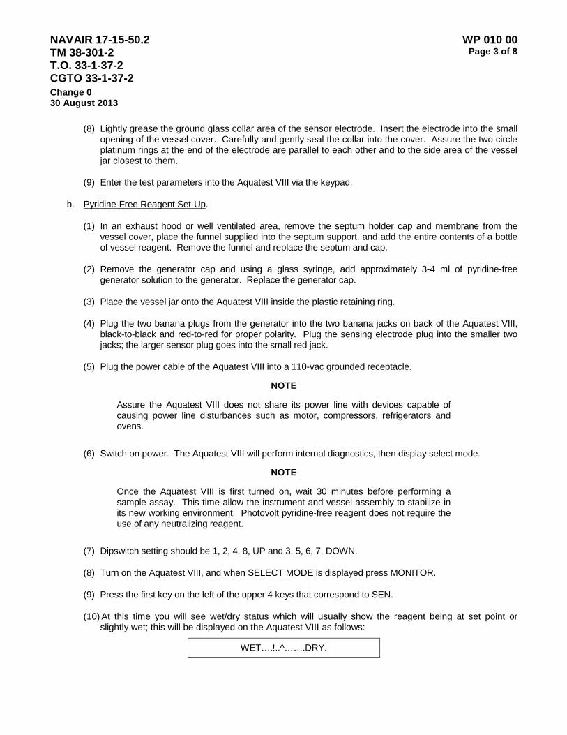
NAVAIR 17-15-50.2 TM 38-301-2 T.O. 33-1-37-2 CGTO 33-1-37-2
WP 010 00 Page 3 of 8
Change 0 30 August 2013
(8) Lightly grease the ground glass collar area of the sensor electrode. Insert the electrode into the small opening of the vessel cover. Carefully and gently seal the collar into the cover. Assure the two circle platinum rings at the end of the electrode are parallel to each other and to the side area of the vessel jar closest to them.
(9) Enter the test parameters into the Aquatest VIII via the keypad.
b. Pyridine-Free Reagent Set-Up.
(1) In an exhaust hood or well ventilated area, remove the septum holder cap and membrane from the vessel cover, place the funnel supplied into the septum support, and add the entire contents of a bottle of vessel reagent. Remove the funnel and replace the septum and cap.
(2) Remove the generator cap and using a glass syringe, add approximately 3-4 ml of pyridine-free generator solution to the generator. Replace the generator cap.
(3) Place the vessel jar onto the Aquatest VIII inside the plastic retaining ring.
(4) Plug the two banana plugs from the generator into the two banana jacks on back of the Aquatest VIII, black-to-black and red-to-red for proper polarity. Plug the sensing electrode plug into the smaller two jacks; the larger sensor plug goes into the small red jack.
(5) Plug the power cable of the Aquatest VIII into a 110-vac grounded receptacle.
NOTE
Assure the Aquatest VIII does not share its power line with devices capable of causing power line disturbances such as motor, compressors, refrigerators and ovens.
(6) Switch on power. The Aquatest VIII will perform internal diagnostics, then display select mode.
NOTE
Once the Aquatest VIII is first turned on, wait 30 minutes before performing a sample assay. This time allow the instrument and vessel assembly to stabilize in its new working environment. Photovolt pyridine-free reagent does not require the use of any neutralizing reagent.
(7) Dipswitch setting should be 1, 2, 4, 8, UP and 3, 5, 6, 7, DOWN.
(8) Turn on the Aquatest VIII, and when SELECT MODE is displayed press MONITOR.
(9) Press the first key on the left of the upper 4 keys that correspond to SEN.
(10) At this time you will see wet/dry status which will usually show the reagent being at set point or slightly wet; this will be displayed on the Aquatest VIII as follows:
WET….!..^…….DRY.
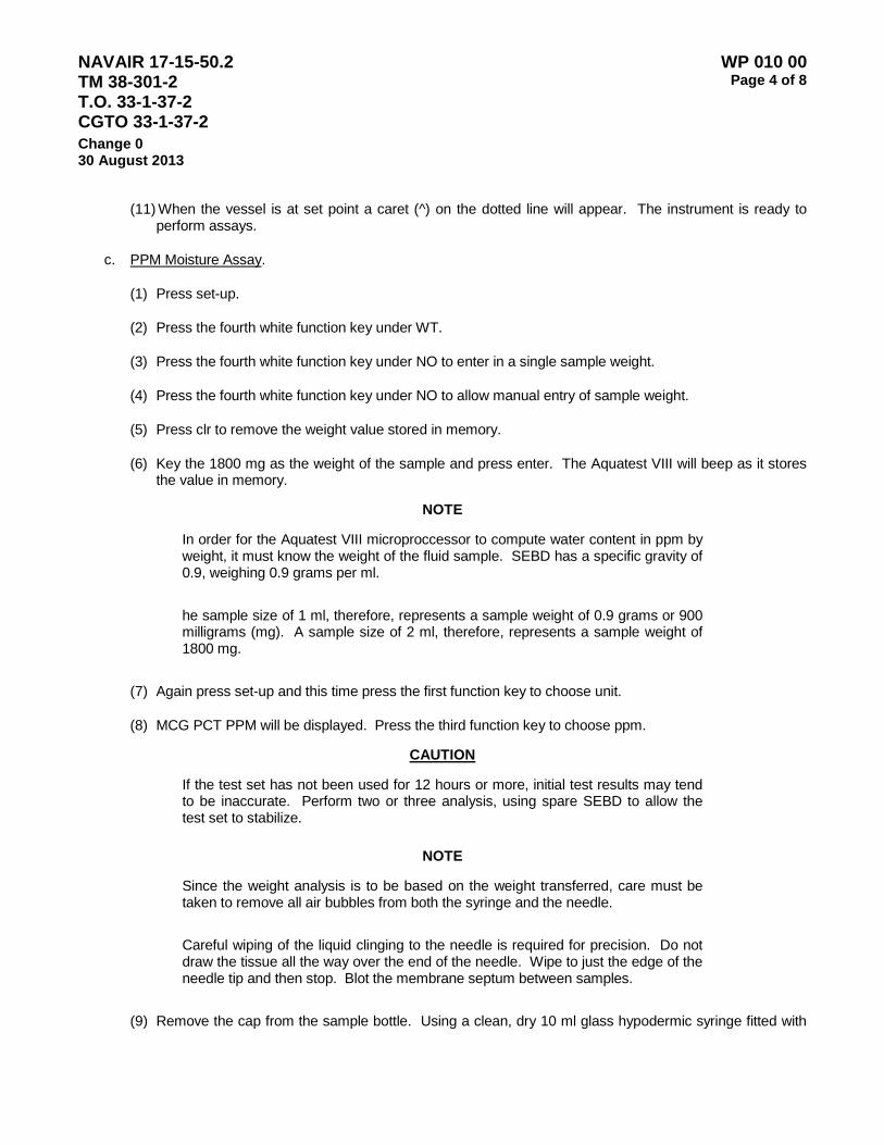
NAVAIR 17-15-50.2 TM 38-301-2 T.O. 33-1-37-2 CGTO 33-1-37-2
WP 010 00 Page 4 of 8
Change 0 30 August 2013
(11) When the vessel is at set point a caret (^) on the dotted line will appear. The instrument is ready to perform assays.
c. PPM Moisture Assay.
(1) Press set-up.
(2) Press the fourth white function key under WT.
(3) Press the fourth white function key under NO to enter in a single sample weight.
(4) Press the fourth white function key under NO to allow manual entry of sample weight.
(5) Press clr to remove the weight value stored in memory.
(6) Key the 1800 mg as the weight of the sample and press enter. The Aquatest VIII will beep as it stores the value in memory.
NOTE
In order for the Aquatest VIII microproccessor to compute water content in ppm by weight, it must know the weight of the fluid sample. SEBD has a specific gravity of 0.9, weighing 0.9 grams per ml.
he sample size of 1 ml, therefore, represents a sample weight of 0.9 grams or 900 milligrams (mg). A sample size of 2 ml, therefore, represents a sample weight of 1800 mg.
(7) Again press set-up and this time press the first function key to choose unit.
(8) MCG PCT PPM will be displayed. Press the third function key to choose ppm.
CAUTION
If the test set has not been used for 12 hours or more, initial test results may tend to be inaccurate. Perform two or three analysis, using spare SEBD to allow the test set to stabilize.
NOTE
Since the weight analysis is to be based on the weight transferred, care must be taken to remove all air bubbles from both the syringe and the needle.
Careful wiping of the liquid clinging to the needle is required for precision. Do not draw the tissue all the way over the end of the needle. Wipe to just the edge of the needle tip and then stop. Blot the membrane septum between samples.
(9) Remove the cap from the sample bottle. Using a clean, dry 10 ml glass hypodermic syringe fitted with
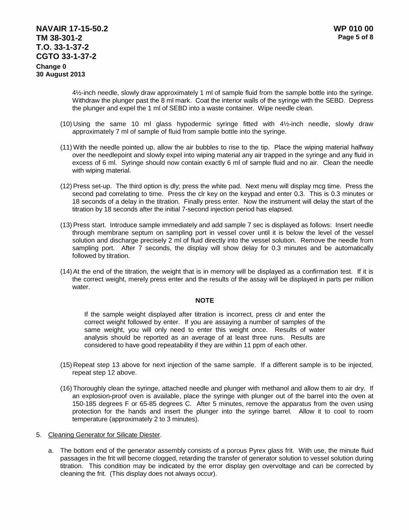
NAVAIR 17-15-50.2 TM 38-301-2 T.O. 33-1-37-2 CGTO 33-1-37-2
WP 010 00 Page 5 of 8
Change 0 30 August 2013
4½-inch needle, slowly draw approximately 1 ml of sample fluid from the sample bottle into the syringe. Withdraw the plunger past the 8 ml mark. Coat the interior walls of the syringe with the SEBD. Depress the plunger and expel the 1 ml of SEBD into a waste container. Wipe needle clean.
(10) Using the same 10 ml glass hypodermic syringe fitted with 4½-inch needle, slowly draw approximately 7 ml of sample of fluid from sample bottle into the syringe.
(11) With the needle pointed up, allow the air bubbles to rise to the tip. Place the wiping material halfway over the needlepoint and slowly expel into wiping material any air trapped in the syringe and any fluid in excess of 6 ml. Syringe should now contain exactly 6 ml of sample fluid and no air. Clean the needle with wiping material.
(12) Press set-up. The third option is dly; press the white pad. Next menu will display mcg time. Press the second pad correlating to time. Press the clr key on the keypad and enter 0.3. This is 0.3 minutes or 18 seconds of a delay in the titration. Finally press enter. Now the instrument will delay the start of the titration by 18 seconds after the initial 7-second injection period has elapsed.
(13) Press start. Introduce sample immediately and add sample 7 sec is displayed as follows: Insert needle through membrane septum on sampling port in vessel cover until it is below the level of the vessel solution and discharge precisely 2 ml of fluid directly into the vessel solution. Remove the needle from sampling port. After 7 seconds, the display will show delay for 0.3 minutes and be automatically followed by titration.
(14) At the end of the titration, the weight that is in memory will be displayed as a confirmation test. If it is the correct weight, merely press enter and the results of the assay will be displayed in parts per million water.
NOTE
If the sample weight displayed after titration is incorrect, press clr and enter the correct weight followed by enter. If you are assaying a number of samples of the same weight, you will only need to enter this weight once. Results of water analysis should be reported as an average of at least three runs. Results are considered to have good repeatability if they are within 11 ppm of each other.
(15) Repeat step 13 above for next injection of the same sample. If a different sample is to be injected, repeat step 12 above.
(16) Thoroughly clean the syringe, attached needle and plunger with methanol and allow them to air dry. If an explosion-proof oven is available, place the syringe with plunger out of the barrel into the oven at 150-185 degrees F or 65-85 degrees C. After 5 minutes, remove the apparatus from the oven using protection for the hands and insert the plunger into the syringe barrel. Allow it to cool to room temperature (approximately 2 to 3 minutes).
5. Cleaning Generator for Silicate Diester.
a. The bottom end of the generator assembly consists of a porous Pyrex glass frit. With use, the minute fluid passages in the frit will become clogged, retarding the transfer of generator solution to vessel solution during titration. This condition may be indicated by the error display gen overvoltage and can be corrected by cleaning the frit. (This display does not always occur).
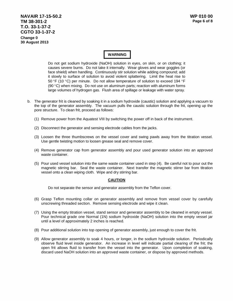
NAVAIR 17-15-50.2 TM 38-301-2 T.O. 33-1-37-2 CGTO 33-1-37-2
WP 010 00 Page 6 of 8
Change 0 30 August 2013 WARNING
Do not get sodium hydroxide (NaOH) solution in eyes, on skin, or on clothing; it causes severe burns. Do not take it internally. Wear gloves and wear goggles (or face shield) when handling. Continuously stir solution while adding compound; add it slowly to surface of solution to avoid violent splattering. Limit the heat rise to 50 °F (10 °C) per minute. Do not allow temperature of solution to exceed 194 °F (90 °C) when mixing. Do not use on aluminum parts; reaction with aluminum forms large volumes of hydrogen gas. Flush area of spillage or leakage with water spray.
b. The generator frit is cleaned by soaking it in a sodium hydroxide (caustic) solution and applying a vacuum to the top of the generator assembly. The vacuum pulls the caustic solution through the frit, opening up the pore structure. To clean frit, proceed as follows:
(1) Remove power from the Aquatest VIII by switching the power off in back of the instrument.
(2) Disconnect the generator and sensing electrode cables from the jacks.
(3) Loosen the three thumbscrews on the vessel cover and swing pawls away from the titration vessel. Use gentle twisting motion to loosen grease seal and remove cover.
(4) Remove generator cap from generator assembly and pour used generator solution into an approved waste container.
(5) Pour used vessel solution into the same waste container used in step (4). Be careful not to pour out the magnetic stirring bar. Seal the waste container. Next transfer the magnetic stirrer bar from titration vessel onto a clean wiping cloth. Wipe and dry stirring bar.
CAUTION
Do not separate the sensor and generator assembly from the Teflon cover.
(6) Grasp Teflon mounting collar on generator assembly and remove from vessel cover by carefully unscrewing threaded section. Remove sensing electrode and wipe it clean.
(7) Using the empty titration vessel, stand sensor and generator assembly to be cleaned in empty vessel. Pour technical grade one Normal (1N) sodium hydroxide (NaOH) solution into the empty vessel jar until a level of approximately 2 inches is reached.
(8) Pour additional solution into top opening of generator assembly, just enough to cover the frit.
(9) Allow generator assembly to soak 4 hours, or longer, in the sodium hydroxide solution. Periodically observe fluid level inside generator. An increase in level will indicate partial clearing of the frit; the open frit allows fluid to transfer from the vessel into the generator. Upon completion of soaking, discard used NaOH solution into an approved waste container, or dispose by approved methods.
NAVAIR 17-15-50.2 TM 38-301-2 T.O. 33-1-37-2 CGTO 33-1-37-2
WP 010 00 Page 7 of 8
Change 0 30 August 2013
(10) Expedite cleaning of porous frit after soaking procedure by the application of a vacuum (not to exceed 15 inches mercury (Hg)) to the generator assembly. Required vacuum can be obtained using the syringe and valve provided with contamination Analysis Kit, part No. 57L414. Locally fabricate required adapters to connect vacuum source to generator, using modified rubber or cork stopper to connect vacuum line to open end of generator.
(11) Place fresh sodium hydroxide solution in emptied titration vessel, enough to partially cover the generator assembly when it is placed in the titration vessel. Apply vacuum to generator assembly until caustic cleaning solution flows freely from the vessel jar to the inside of the generator. Carefully observe fluid level in generator and assure that fluid is not sucked into vacuum line. A filtering flask may be installed as a trap between the generator and the vacuum pump. If required, pour excess fluid from generator assembly to waste.
(12) When frit has been cleaned, remove sensor and generator assembly from vessel jar and discard caustic solution into an approved waste container, or dispose by approved methods. Rinse generator assembly and vessel jar using generous amounts of water, preferably hot.
(13) Return generator assembly to the vessel jar and partially fill vessel with water (tap or deionized). Using vacuum procedure specified in steps (10) and (11), flush frit with water to remove residual caustic solution.
(14) Remove generator assembly from vessel jar and discard water.
WARNING
Methanol is flammable - Do not use near open flames, near welding area, or on hot surfaces. Do not smoke when using it, and do not use it where others are smoking. Prolonged or repeated inhalation of vapor can cause eye irritation, drowsiness, and headache. Ingestion may be fatal or may cause eye damage. If vapor contacts eyes, immediately flush eyes with large amounts of water. Immediately remove solvent-saturated clothing. If vapor cause drowsiness, remove affected person from area and expose to fresh air. When handling or applying liquid at air-exhausted workbench, wear approved goggles and gloves. When handling or applying liquid at unexhausted workbench, wear approved respirator, goggles and gloves.
(15) Remove residual water from generator assembly by pulling Methanol through generator with vacuum, as described in steps (j) and (k), and then drying in oven (if available) at 150 to 185 °F (65 to 85 °C) for a period of 2 hours. If no oven is available, allow to air dry before use. Store generator in desiccator if available, until needed.
(16) In some cases, because of lack of equipment, it may not be possible to clean the frit in shipboard laboratories. In these cases the laboratory should change the generator assembly. The assemblies which need cleaning of the frits should be retained and subsequently taken to a shore based laboratory where cleaning can be accomplished.
NAVAIR 17-15-50.2 TM 38-301-2 T.O. 33-1-37-2 CGTO 33-1-37-2
WP 010 00 Page 8 of 8
Change 0 30 August 2013 5. Calibration.
NOTE
The Aquatest VIII does not require calibration. However, a user calibration procedure is provided so that the user can quickly confirm that the instrument is indeed titrating water accurately. User calibration is generally done every 6 months or as needed (whenever erroneous results are suspected).
a. Set Aquatest VIII to mcg mode (page 4, sections C.(7) and C.(8) Moisture Assay).
NOTE
In preparation for the following, fill beaker or other clean container with small amount of tap or deionized water. Set adapter on syringe to 1.0 microliter mark on syringe barrel. Pump syringe several times while needle is submerged in water to remove air. Remove membrane from sample port to enable needle (shorter length) to be below vessel solution.
b. Press start. Introduce sample immediately after add sample 7 sec is displayed as follows: Insert needle of a gas tight 2 micro liter syringe with built in Chaney adapter (Section 2, page 1) directly through the septum on the sampling port in the vessel cover until it extends below the level of the vessel solution and discharge precisely 1.0 micro liter of water into the vessel solution. After a brief moment, remove syringe and needle from sampling port and replace membrane. After 7 seconds, the display will show delay and be automatically followed by titration. Established that; you obtain 1000+50 micrograms of water. Repeat additions until you have 5-10 replicates to determine precision (standard deviation less than or equal to 50 mcg is acceptable). Flush needle several times with water prior to storing to remove chemicals from Aquatest that will cause corrosion.

NAVAIR 17-15-50.2 TM 38-301-2 T.O. 33-1-37-2 CGTO 33-1-37-2
WP 011 00 Page 1 of 2
Change 0 30 August 2013
PALL WATER TEST
1. Scope. This test method covers the determination of the total of dissolved water in hydraulic, transmission, and electronic cooling system fluids.
2. Summary of Method. The Pall Water Sensor is a small portable device that provides an electronic display reading of percent dissolved water through the use of in-system, bottle, or dipstick probes.
3. Equipment/Apparatus/Materials.
Description Manufacturer Part Number NSN
Water Sensor Pall WS04B04 Probes Pall Battery Charger Isopropyl Alcohol kim wipes A-A-1432A 7920-00-721-8884 paper towels 7920-00-823-9773
4. Standards/Standardization/Calibration. A calibration validation procedure is used to ensure that the unit is operating properly and within calibration tolerances.
5. References/Guidelines. Pall TD513 Water Sensor Manual
6. Quick Use Instructions to Monitor Fluid Water Content.
a. Charge unit. Plug power adapter into a 110V wall outlet for 24 hours (see battery, page 6 of the manual).
b. Connect sensor. Attach the sensor to the display cable by rotating the outer ring clockwise.
c. Press “PWR” to turn unit “on”.
Measure? Yes Next
d. Press “YES” to accept measurement mode.
I.D.# Next Yes No
e. Press “YES” to continue without entering a sample identification number.
(1) Press “FLUID TEMP” to select a different fluid to be measured.
73F H-83282 218

NAVAIR 17-15-50.2 TM 38-301-2 T.O. 33-1-37-2 CGTO 33-1-37-2
WP 011 00 Page 2 of 2
Change 0 30 August 2013
(2) Press “NEXT WATER” to change fluid type.
Use PRF-87252? Yes No Next
(3) Press “YES” to accept the fluid type.
Fluid Selected
OR
(4) Press “NO” to go back to step e without changing the fluid type.
73F H-83282 218
f. Press “YES” if proper measurement has been displayed.
Store this data? Yes No
g. Press “YES” to save measurement and return to step c.
Measure? Yes Next
OR
h. Press “NO” not to save and return to step c.
Measure? Yes No
i. Press “PWR” to turn unit off.
NOTE
The Pall Water Sensor information has been included in the JOAP Manual with permission from Pall Aerospace.

NAVAIR 17-15-50.2 TM 38-301-2 T.O. 33-1-37-2 CGTO 33-1-37-2
WP 012 00 Page 1 of 2
Change 0 30 August 2013
BLOTTER SPOT TEST LABORATORY OPERATING PROCEDURES
1. Scope. This method provides a qualitative test for amount of insoluble contaminants and/or dispersant ability of used lubricants from diesel engines.
2. Summary of Method. After vigorous shaking, one drop of the used lubricant is placed in the center of filter paper. The oil spot is allowed to develop for 15 minutes, and the resulting spot is evaluated for total contaminants, coolant contaminants, and dispersant effectiveness.
3. Definitions.
a. Dispersancy. Dispersancy is a measure of the ability of the oil to support debris. Dispersancy additives in most modern lubricants keep contaminants suspended in the oil rather than allowing them to be deposited on engine surfaces.
b. Contaminants. Contaminants are soluble and insoluble materials that accumulate in used oils from many sources and, that if allowed to accumulate beyond recommended guidelines, may become harmful to the equipment. Some examples are fuel, oxidation products, soot, dust, wear debris, water and coolant.
4. Equipment/Apparatus/Materials.
Description Manufacturer Part Number NSN
filter pape (circles or sheets)r
Kim wipes A-A-1432A 7920-00-721-8884 paper towels 7920-00-823-9773 paper clips 1⁄16-inch diameter
5. Standards/Standardization/Calibration. It is recommended that the operator prepare blotter spots of new oils
to become familiar with normal spot sizes and patterns. Although wire size is not critical, it is important that the same size wire is used each time to drop the oil on the filter paper.
6. Operation/Procedures.
a. Shake sample vigorously to ensure homogeneity.
b. Using a suitable wire, place one drop of the oil sample in the center of the filter paper.
c. Allow 15 minutes for the oil spot to spread and dry.
d. Evaluate the oil spot for the following characteristics: solids contamination, dispersancy, and coolant contaminants.
NAVAIR 17-15-50.2 TM 38-301-2 T.O. 33-1-37-2 CGTO 33-1-37-2
WP 012 00 Page 2 of 2
Change 0 30 August 2013 7. References/Guidelines.
a. Solids Contamination. Distinctive patterns develop after placing the oil on the filter paper. Evaluation of solids contamination becomes obvious after experience is gained for a given type of equipment. Solids contamination is evaluated as being light, medium, or heavy. Care should be exercised if solids suddenly disappear and an oil or oil filter change has not been reported. This condition can indicate a loss of dispersion and a “drop out” of solids that cannot be detected by any of the available test methods. When heavy solids are confirmed or in the case of solids “drop out”, a recommendation to change the oil and the oil filter should be issued.
b. Dispersancy. Dispersancy is evaluated as good, fair, or poor. The spots for oils with good dispersion are characterized by fuzzy or lacy patterns, with solids carried well out in the paper. Generally, the greater the size of the spot and spread of the solids as compared with the initial spot, the better the dispersion. As the oil’s dispersion is reduced, the spot becomes smaller. The spots for oils with poor dispersion have sharp and distinct peripheries and the spots after 15 minutes are not much larger than the initial spots. A recommendation to change oil should be issued if dispersion is poor.
c. Coolant Contaminants. Water and other coolant contaminants will reduce or destroy dispersant additives. Spots that form are similar to those described for the dispersion guidelines. In addition, these spots will often appear to be wet long after normal spots are dry.
8. Reports. Record test results as follows.
a. Total Contaminants - (1) Light, (2) Medium, (3) Heavy.
b. Coolant Contaminants - (1) Not Detected, (2) Present.
c. Dispersion- (1) Good, (2) Fair, (3) Poor.
Using the numerical codes above, the best quality oil would be rated 1, 1, 1, while the worst possible case is 3, 2, 3. When numerical coding is used, it is not necessary to save the actual blotter spot record, since data can still be trended.

NAVAIR 17-15-50.2 TM 38-301-2 T.O. 33-1-37-2 CGTO 33-1-37-2
WP 012 00 Page 1 of 12
Change 0 30 August 2013
FERROGRAPHIC ANALYSIS LABORATORY REQUIREMENTS AND OPERATING PROCEDURES
1. Army CH-47D Helicopter Swash Plate/Scissors and Sleeve Assemblies.
a. Scope. This procedure is used to determine the size, shape and type of wear metal particles being generated by a piece of equipment as well as the mode of wear (e.g., spalling, rubbing and cutting) producing the particles.
b. Summary of Method. The grease sample is diluted with a fixer solution to break down the bonding material of the grease. The liquid is then allowed to flow across a substrate mounted over a magnetic field gradient. The magnetic field aligns the particles in strings along the slide and the fixer solution is passed across the substrate to remove the residual grease. After drying, the substrate is analyzed under a Ferroscope. Laboratory grease evaluation procedures are contained in Volume III.
c. Equipment/Apparatus/Materials. The equipment required is the analytical Ferrograph and Ferroscope.
Description Manufacturer Part Number NSN
kim wipes A-A-1432A 7920-00-721-8884 paper towels 7920-00-823-9773 tetrachloroethane Ferrograph Ferroscope tygon tubing turret tubing vials pipette
d. Standards. None
e. Operation/Procedures.
WARNING
Repeated or prolonged contact with liquid tetrachloroethylene or inhalation of vapors can cause skin and eye irritation, dermatitis, narcotic effects, and liver and kidney damage. After prolonged skin contact, wash the contacted area with soap and water. Remove contaminated clothing. If vapors cause irritation, get to fresh air. For prolonged over-exposure, get medical help. When handling liquid in vapor-degreasing tanks with hinged cover and air exhaust, or at air-exhausted workbench, wear approved gloves and goggles if contact with liquid is likely. When handling liquid at open, unexhausted workbench, wear approved respirator, gloves, and goggles. Dispose of liquid-soaked rags in approved metal containers.
NAVAIR 17-15-50.2 TM 38-301-2 T.O. 33-1-37-2 CGTO 33-1-37-2
WP 012 00 Page 2 of 12
Change 0 30 August 2013
(1) Measure 1 cubic centimeter (cc) of grease and place it into a 16x150 millimeter (mm) test tube. Add approximately 7 milliliters (ml) of tetrachloroethylene and shake until thoroughly dissolved.
(2) Remove the glass substrate from the package. With the dot in the lower left hand corner, position the substrate so that the top edge is elevated and resting on top of the magnet assembly. The drain tube supports the bottom edge of the substrate.
(3) Cut a 4-inch long piece of Tygon tubing and two pieces of turret tubing, one piece 2 inches long and one piece 8 inches long. Cut both ends of the turret tubing at a 45-degree angle and insert an end of each piece into the Tygon tubing. Place the 2-inch long piece of turret tubing in the delivery arm with the 45-degree angle open end facing the drain tube.
(4) The sample and rinse vials are supported at least 3½ inches above the peristaltic pump. The pump itself is not used. The end of the 8-inch piece of turret tubing is inserted into the sample vial, supported by a double-notched stopper (one notch for the turret tube and one to equalize pressure).
(5) A screw clamp is placed on the Tygon tubing. A slight suction is applied at the delivery arm end of the tubing and the clamp is loosened long enough to allow the sample to flow halfway through the tube. The clamp is tightened, the suction removed, and the delivery arm is lowered until the exit end of the turret tube touches the substrate. The delivery arm is then backed off slightly.
(6) The clamp is released very slowly allowing the sample to flow evenly down the substrate. When the volume in the sample bottle reaches approximately ¼ inch, the Tygon tube is clamped and the end of the turret tube is placed in the rinse vial. The clamp is then released and the substrate rinsed with fixer solution. Allow several air gaps in the turret tube by opening and closing the clamp several times to ensure that the oil does not back up into the rinse.
(7) Allow the substrate to dry. Remove the substrate by lifting upon the exit end and pulling it straight out of the holder so as not to break the completed Ferrogram. Number the Ferrogram and the Ferrogram cover with the component serial number and sample number. This can be done using thin typewriter correction tape or a glass-marking pen.
(8) The Ferrogram is then analyzed using the Ferroscope. The wear metal debris is compared to the guideline photographs for degrees of severity. The results are recorded on the Ferrograph worksheet (see Ferrogram Analysis Report Sheet, page 11,), and filed by component serial number along with the substrate. Worksheets and substrates will be kept on file for a minimum of one year.
2. Supplemental Ferrographic Oil Analysis Procedures (Army). This is a supplemental procedure used by the Army in the analysis of suspect aeronautical oil samples. Suspect oil samples are defined as those for which one or more of the following diagnostic indicators are observed: chip light; vibration; metal on screens or filters; oil of unusual color, odor, or high solids content; and oil samples having abnormal spectrometric trends or wear metal content.
a. Scope. This procedure captures information relative to the size, shape, and types of wear metal particles and debris too large to be detected by spectrometric analysis.
b. Summary of Method. The oil sample is diluted with a fixer solution to increase the rate of flow. The sample is then analyzed using the Direct Reading (DR) Ferrograph and appropriate guidelines, to
NAVAIR 17-15-50.2 TM 38-301-2 T.O. 33-1-37-2 CGTO 33-1-37-2
WP 012 00 Page 3 of 12
Change 0 30 August 2013
quantify both large and small wear particles. If the established DR guidelines are exceeded, the development of a Ferrogram and its examination under the Ferroscope is required.
c. Equipment/Apparatus/Materials. The equipment required is the DR Ferrograph, analytical Ferrograph or Ferrograph Machine III (FMIII), and the Ferroscope.
d. Standards. None.
e. Operation/Procedures.
WARNING
Both the fixer reagent and filtered oil contain a nonflammable chlorinated hydrocarbon. Its vapor however is harmful if breathed. Ensure adequate ventilation. Avoid contact with skin. Do not take internally. Serious injury may result if these cautions are not followed.
f. Direct Reading (DR) Ferrograph.
(1) Press the on/off switch on the rear of the DR unit to the on position. At this time the “INSERT TUBE LED” lights, and both windows display 0.0. This is a standby state during which the DR warms up. NOTE: The DR should be turned on at least 30 minutes before testing is begun.
(2) Heat the sample oil to approximately 149 °F (65 °C) and vigorously shake the sample in the original container until all sediment is homogeneously suspended in the oil.
(3) Turn the drain pump knob so that the white indicators line up.
(4) Using the dispenser assembly on the fixer reagent bottle, pump exactly 2 ml of fixer reagent/solvent into a new test vial.
(5) Using a pipette dispenser, add exactly 1 ml of sample lubricant to the same test vial and mix thoroughly.
(6) Place the vial in the holder and prepare the DR for testing by:
(a) Remove the precipitator tube from its shipping bag.
(b) Carefully raise the clamp assembly and place the glass section of the precipitator tube in the groove provided. Be sure not to touch the glass tube with your fingers. This could interfere with zeroing the instrument (see paragraph (9)). As you slide the tube in, note the small lever at the rear as you position the tube (you will hear a slight click).
(c) When the precipitator tube is correctly positioned the “INSERT TUBE LED” goes off and the “PRIME LED” lights: Gently lower the clamp to lock the tube into position on the magnet.
(d) Place the Tygon end of the tube on the inlet nipple.
(e) Run the opposite length of the tube around the tube guide at the left of the DR. It fits behind a lip.

NAVAIR 17-15-50.2 TM 38-301-2 T.O. 33-1-37-2 CGTO 33-1-37-2
WP 012 00 Page 4 of 12
Change 0 30 August 2013
(f) Run the tube through the two spring supports up to the sample vial. It is better to have the excess length near the vial and a relative length down to the guide.
(g) Place the opposite end of the tube into the vial. This should touch the bottom of the vial so that the entire sample will be drawn out during the test.
(h) Make sure that the waste bottle is placed in the well, and place the drain tube permanently attached to the outlet nipple into the waste bottle.
(7) Confirm that the “INSERT TUBE LED” is off, and that the “PRIME LED” is on. If the opposite occurs, readjust the precipitator tube against the actuator arm.
(8) Press the PRIME pushbutton. This action causes the PRIME LED to go off and both the DL ZERO and DS ZERO LEDS to come on for approximately 2 seconds (at this time the DR circuitry automatically zeros on the empty precipitator tube). When zeroing is complete, the DS LED goes off, and only the DL LED is on, indicating the DR is functioning correctly.
(9) Create a suction in the precipitator tube by slowly turning the drain pump knob in a clockwise direction. This action draws the mixed fluid from the sample vial. When the fluid level is drawn at a level below the sample vial, the siphoning action takes over, and the oil flows by itself. Stop turning when the white line on the knob lines up with the other line of the DR. When the fluid passes the second light path in the test area, the auto-zero sequence is initiated. Again, both the DL and DS LEDS are on. When the DR has zeroed on the sample, the 2 LEDS go off; the windows display 0.0; and the RUN LED lights. This indicates that the test is in progress and typically requires about 5 minutes to complete. As the solution flows over the test area, the display increments from 0.0, indicating that residual wear particles are dropping into the 2 light paths. When the liquid stops flowing, record the readings.
(10) Turn the drain pump knob slowly in a clockwise direction after all the oil has passed over the test area. This action empties the pumping system into the waste bottle.
(11) Remove the precipitator tube from the test area.
(12) Discard the precipitator tube, sample vial, and pipette tip before doing another test.
g. Ferrogram Preparation. There are three different methods of preparing ferrogams; the standard method, the fast method that employs the older model Analytical Ferrograph, and the new method that employs the newer model FMIII.
h. The Standard Method.
(1) Remove the Ferrogram substrate from the sealed bag and protective envelope.
CAUTION
Avoid touching the surface of the substrate with the fingers. Always handle the substrate by the edge.
NAVAIR 17-15-50.2 TM 38-301-2 T.O. 33-1-37-2 CGTO 33-1-37-2
WP 012 00 Page 5 of 12
Change 0 30 August 2013
(2) Install the substrate in the substrate-holding fixture by retracting the spring-loaded positioning pin and inserting the substrate into the holding fixture as far as possible. When positioning the substrate, make sure that the black dot appears in the lower left-hand corner.
(3) Remove the turret tube from the sealed bag and cut one end at a 45-degree angle. This will become the exit end of the tubing.
(4) Press the exit end of the turret tube with the 45-degree angle facing the operator into the delivery arm holding groove. Notice the index mark on the delivery arm and observe the distance from the index mark to the end of the arm. Now extend the turret tube an equal distance beyond the end of the delivery arm.
(5) Press the turret tube into the exit notch on the downstream side of the pump.
(6) Release the pump turret arm locking screw by turning the knurled nut counterclockwise. Open the pump turret arms, thread the tube around the turret and then partially close the turret arms.
(7) Press the turret tube into the pump entry tube clamp on the upstream side of the pump and secure it by turning the knurled eccentric clamp lever counterclockwise. Tighten the turret arms.
NAVAIR 17-15-50.2 TM 38-301-2 T.O. 33-1-37-2 CGTO 33-1-37-2
WP 012 00 Page 6 of 12
Change 0 30 August 2013
(8) Inspect the drain tube to make sure no sections of it are liquid filled. Draw out any liquid with a cotton swab.
(9) Insert the drain tube into the drain tube holder and rotate the drain tube holding fixture counterclockwise until it is centered on the substrate.
(10) Lower the notched end of the drain tube until the tip touches the substrate.
(11) Prepare the sample by first heating it to 149 °F (65 °C) and then shaking vigorously until all sediment is homogeneously suspended in the oil.
(12) Discharge 5 ml of fixer reagent into a sample vial (to be used as a wash), and place the vial in the rack slot nearest the magnet assembly.
(13) Discharge 1 ml of fixer reagent into a second sample vial and place it in one of the empty vial rack slots. Add 3 ml of oil sample to the vial containing 1 ml of fixer reagent and mix thoroughly. This can be done with a mechanical shaker or by hand if care is taken to cover the mouth of the vial with a non-contaminating material or stopper.
(14) Place the sample vial back into the rack. Because of the influence of the field strength of the magnet, place the vial containing the sample mixture in the position farthest away from the magnet assembly.
(15) Install the spring clip assembly on the oil sample vial.
(16) Insert the suction end of the turret tube into the bottom of the sample vial and press the tube into the spring clip.
(17) Lower the delivery arm until the exit end of the tube touches the substrate. Then, back off the delivery arm approximately 1 mm so that the liquid does not drip, but flows freely onto the substrate.
(18) Place the power switch to the ON position, set the timer to 15 minutes, and depress the red timer START button to start the sample cycle.
(19) When the sample vial is empty, reset the timer to 10 minutes and depress the red timer START button to start the wash cycle.
(20) Remove the spring clip and turret tube from the empty vial and transfer both to the vial containing the fixer reagent wash solution.
(21) Introduce three air gaps into the flow in the turret tube by removing the end of the turret tube momentarily from the wash solution and then reinserting it back into the solution. This prevents the oil from diffusing back into the wash solution.
(22) Immediately after the pump shuts off, lift the turret tube off of the ferrogram by raising the delivery arm.
(23) When flow through the drain tube has stopped (approximately 1 minute) lift the drain tube holder with the drain tube in it, and rotate it 90 degrees clockwise.
NAVAIR 17-15-50.2 TM 38-301-2 T.O. 33-1-37-2 CGTO 33-1-37-2
WP 012 00 Page 7 of 12
Change 0 30 August 2013
(24) Allow sufficient time for the ferrogram to dry; do not remove the ferrogram until all of the fixer reagent has evaporated.
(25) Release the spring-loaded positioning pin and lift the ferrogram up vertically.
CAUTION
Do not drag the ferrogram across the magnet as this could disturb the particles on the ferrogram.
(26) Label the ferrogram and ferrogram cover with the component serial number and sample number. This can be done using typewriter correction tape or a glass marking pen.
(27) Discard the turret tube and the sample and fixer reagent vials.
i. The Fast Method.
(1) Measure 5 ml of sample and place into a 16x150 mm test tube. Add approximately 7 ml of fixer reagent/solvent and shake until thoroughly mixed.
(2) Follow steps (3) through (4) of the Standard Method above.
(a) Follow step (2) from the Standard Method above.
(b) Cut a 4-inch long piece of Tygon tubing, a 2-inch long piece of turret tubing, and an 8-inch piece of turret tubing. Cut the ends of the turret tubing at a 45-degree angle to the axis of the tubing. Insert an end of each piece of turret tubing into the Tygon tubing. Place the 2-inch long piece of turret tubing into the delivery arm with the 45-degree angle open end facing the operator.
(c) Follow step (4) from the Standard Method above.
(3) The sample and rinse vials are supported 3½ inches above the peristaltic pump. The pump itself is not used. The free end of the turret tubing is inserted into the sample vial, supported by a double-notched stopper (one notch for the turret tube and one to equalize the air pressure).
(4) A screw clamp is placed on the Tygon tubing section. A slight suction is applied at the delivery arm end of the tubing and the clamp is loosened long enough to allow the sample to flow halfway through the tube. The clamp is tightened, the suction removed, and the delivery arm is lowered until the exit end of the turret tube touches the substrate. The delivery arm is then backed off slightly.
(5) The clamp is initially released very slowly allowing the sample to establish a path down the substrate. Once the path is established, the sample is allowed to flow at a faster rate. When the volume in the sample vial reaches approximately ¼ inch, the tube is clamped and the end of the turret tube is placed in the rinse vial. The clamp is then released and the substrate rinsed with the fixer solution. Allow several air gaps in the turret tube by opening and closing the clamp several times. This will ensure that the oil does not back up into the rinse.
(6) Follow steps (25) through (27) for the Standard Method above.
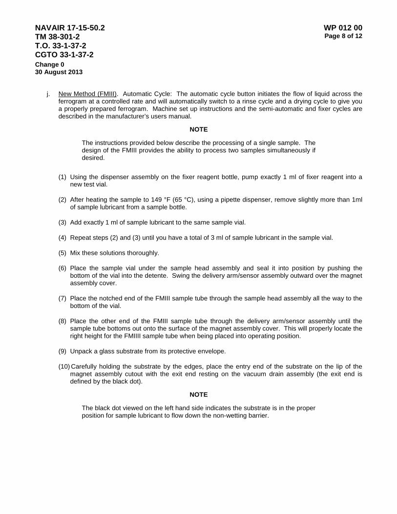
NAVAIR 17-15-50.2 TM 38-301-2 T.O. 33-1-37-2 CGTO 33-1-37-2
WP 012 00 Page 8 of 12
Change 0 30 August 2013
j. New Method (FMIII). Automatic Cycle: The automatic cycle button initiates the flow of liquid across the ferrogram at a controlled rate and will automatically switch to a rinse cycle and a drying cycle to give you a properly prepared ferrogram. Machine set up instructions and the semi-automatic and fixer cycles are described in the manufacturer’s users manual.
NOTE
The instructions provided below describe the processing of a single sample. The design of the FMIII provides the ability to process two samples simultaneously if desired.
(1) Using the dispenser assembly on the fixer reagent bottle, pump exactly 1 ml of fixer reagent into a new test vial.
(2) After heating the sample to 149 °F (65 °C), using a pipette dispenser, remove slightly more than 1ml of sample lubricant from a sample bottle.
(3) Add exactly 1 ml of sample lubricant to the same sample vial.
(4) Repeat steps (2) and (3) until you have a total of 3 ml of sample lubricant in the sample vial.
(5) Mix these solutions thoroughly.
(6) Place the sample vial under the sample head assembly and seal it into position by pushing the bottom of the vial into the detente. Swing the delivery arm/sensor assembly outward over the magnet assembly cover.
(7) Place the notched end of the FMIII sample tube through the sample head assembly all the way to the bottom of the vial.
(8) Place the other end of the FMIII sample tube through the delivery arm/sensor assembly until the sample tube bottoms out onto the surface of the magnet assembly cover. This will properly locate the right height for the FMIIII sample tube when being placed into operating position.
(9) Unpack a glass substrate from its protective envelope.
(10) Carefully holding the substrate by the edges, place the entry end of the substrate on the lip of the magnet assembly cutout with the exit end resting on the vacuum drain assembly (the exit end is defined by the black dot).
NOTE
The black dot viewed on the left hand side indicates the substrate is in the proper position for sample lubricant to flow down the non-wetting barrier.
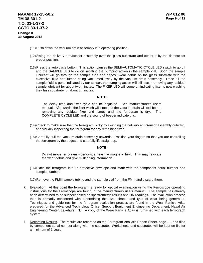
NAVAIR 17-15-50.2 TM 38-301-2 T.O. 33-1-37-2 CGTO 33-1-37-2
WP 012 00 Page 9 of 12
Change 0 30 August 2013
(11) Push down the vacuum drain assembly into operating position.
(12) Swing the delivery arm/sensor assembly over the glass substrate and center it by the detente for proper position.
(13) Press the auto cycle button. This action causes the SEMI-AUTOMATIC CYCLE LED switch to go off and the SAMPLE LED to go on initiating the pumping action in the sample vial. Soon the sample lubricant will go through the sample tube and deposit wear debris on the glass substrate with the excessive fluid and fumes being vacuumed away by the vacuum drain assembly. Once all the sample fluid is gone indicated by our sensor, the pumping action will still occur removing any residual sample lubricant for about two minutes. The FIXER LED will come on indicating fixer is now washing the glass substrate for about 8 minutes.
NOTE
The delay time and fixer cycle can be adjusted. See manufacturer’s users manual. Afterwards, the fixer wash will stop and the vacuum drain will still be on, removing any residual fixer and fumes until the ferrogram is dry. The COMPLETE CYCLE LED and the sound of beeper indicate this.
(14) Check to make sure that the ferrogram is dry by swinging the delivery arm/sensor assembly outward, and visually inspecting the ferrogram for any remaining fixer.
(15) Carefully pull the vacuum drain assembly upwards. Position your fingers so that you are controlling the ferrogram by the edges and carefully lift straight up.
NOTE
Do not move ferrogram side-to-side near the magnetic field. This may relocate the wear debris and give misleading information.
(16) Place the ferrogram into its protective envelope and mark with the component serial number and sample numbers.
(17) Remove the FMIII sample tubing and the sample vial from the FMIII and discard them.
k. Evaluation. At this point the ferrogram is ready for optical examination using the Ferroscope operating instructions for the Ferroscope are found in the manufacturers users manual. The sample has already been determined to be suspect based on spectrometric results and DR readings. The evaluation process then is primarily concerned with determining the size, shape, and type of wear being generated. Techniques and guidelines for the ferrogram evaluation process are found in the Wear Particle Atlas prepared for the Advanced Technology Office, Support Equipment Engineering Department, Naval Air Engineering Center, Lakehurst, NJ. A copy of the Wear Particle Atlas is furnished with each ferrograph system.
l. Recording Results. The results are recorded on the Ferrogram Analysis Report Sheet, page 11, and filed by component serial number along with the substrate. Worksheets and substrates will be kept on file for a minimum of 1 year.
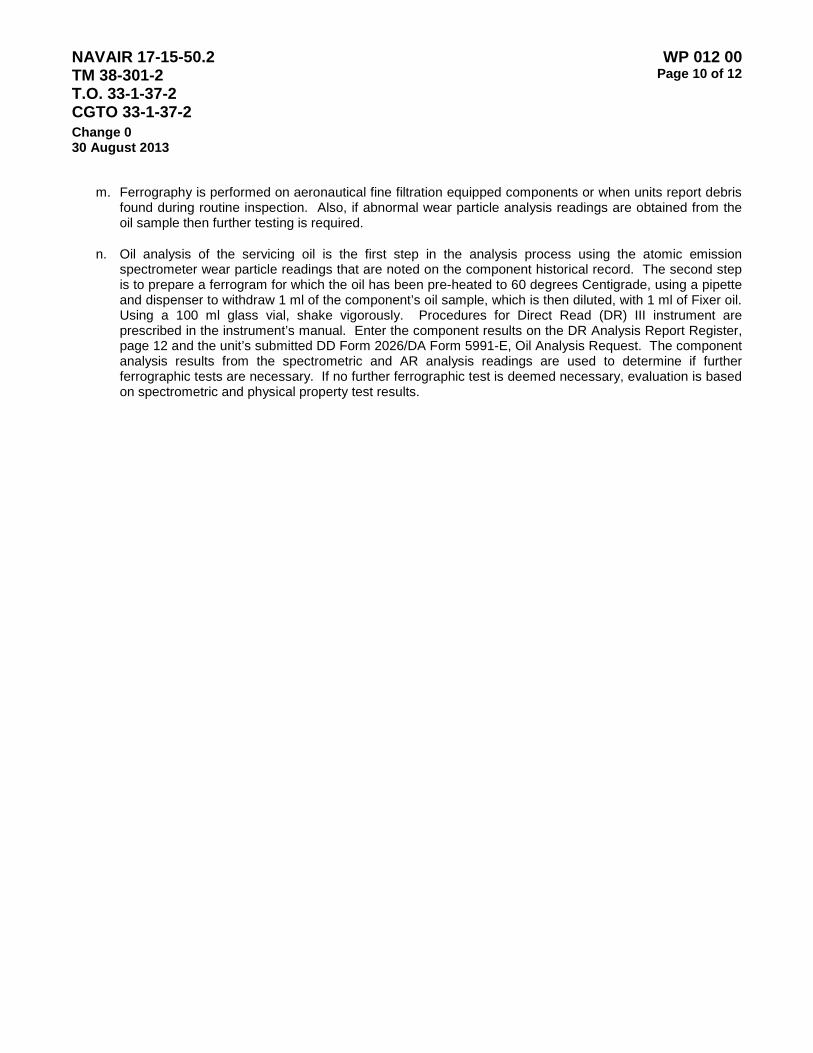
NAVAIR 17-15-50.2 TM 38-301-2 T.O. 33-1-37-2 CGTO 33-1-37-2
WP 012 00 Page 10 of 12
Change 0 30 August 2013
m. Ferrography is performed on aeronautical fine filtration equipped components or when units report debris found during routine inspection. Also, if abnormal wear particle analysis readings are obtained from the oil sample then further testing is required.
n. Oil analysis of the servicing oil is the first step in the analysis process using the atomic emission spectrometer wear particle readings that are noted on the component historical record. The second step is to prepare a ferrogram for which the oil has been pre-heated to 60 degrees Centigrade, using a pipette and dispenser to withdraw 1 ml of the component’s oil sample, which is then diluted, with 1 ml of Fixer oil. Using a 100 ml glass vial, shake vigorously. Procedures for Direct Read (DR) III instrument are prescribed in the instrument’s manual. Enter the component results on the DR Analysis Report Register, page 12 and the unit’s submitted DD Form 2026/DA Form 5991-E, Oil Analysis Request. The component analysis results from the spectrometric and AR analysis readings are used to determine if further ferrographic tests are necessary. If no further ferrographic test is deemed necessary, evaluation is based on spectrometric and physical property test results.

NAVAIR 17-15-50.2 TM 38-301-2 T.O. 33-1-37-2 CGTO 33-1-37-2
WP 012 00 Page 11 of 12
Change 0 30 August 2013
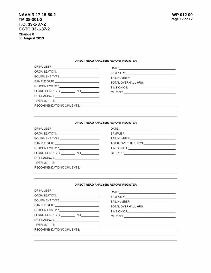
NAVAIR 17-15-50.2 TM 38-301-2 T.O. 33-1-37-2 CGTO 33-1-37-2
WP 012 00 Page 12 of 12
Change 0 30 August 2013
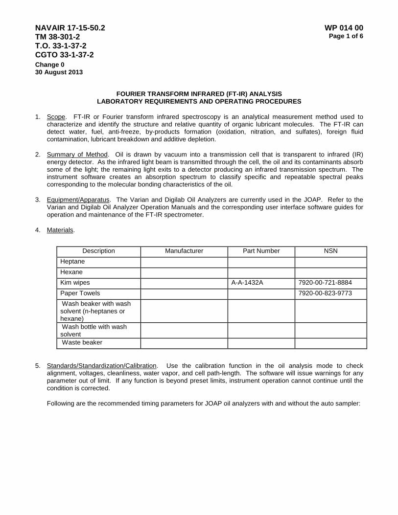
NAVAIR 17-15-50.2 TM 38-301-2 T.O. 33-1-37-2 CGTO 33-1-37-2
WP 014 00 Page 1 of 6
Change 0 30 August 2013
FOURIER TRANSFORM INFRARED (FT-IR) ANALYSIS LABORATORY REQUIREMENTS AND OPERATING PROCEDURES
1. Scope. FT-IR or Fourier transform infrared spectroscopy is an analytical measurement method used to characterize and identify the structure and relative quantity of organic lubricant molecules. The FT-IR can detect water, fuel, anti-freeze, by-products formation (oxidation, nitration, and sulfates), foreign fluid contamination, lubricant breakdown and additive depletion.
2. Summary of Method. Oil is drawn by vacuum into a transmission cell that is transparent to infrared (IR) energy detector. As the infrared light beam is transmitted through the cell, the oil and its contaminants absorb some of the light; the remaining light exits to a detector producing an infrared transmission spectrum. The instrument software creates an absorption spectrum to classify specific and repeatable spectral peaks corresponding to the molecular bonding characteristics of the oil.
3. Equipment/Apparatus. The Varian and Digilab Oil Analyzers are currently used in the JOAP. Refer to the Varian and Digilab Oil Analyzer Operation Manuals and the corresponding user interface software guides for operation and maintenance of the FT-IR spectrometer.
4. Materials.
Description Manufacturer Part Number NSN
Heptane Hexane Kim wipes A-A-1432A 7920-00-721-8884 Paper Towels 7920-00-823-9773 Wash beaker with wash solvent (n-heptanes or hexane)
Wash bottle with wash solvent
Waste beaker
5. Standards/Standardization/Calibration. Use the calibration function in the oil analysis mode to check alignment, voltages, cleanliness, water vapor, and cell path-length. The software will issue warnings for any parameter out of limit. If any function is beyond preset limits, instrument operation cannot continue until the condition is corrected.
Following are the recommended timing parameters for JOAP oil analyzers with and without the auto sampler:
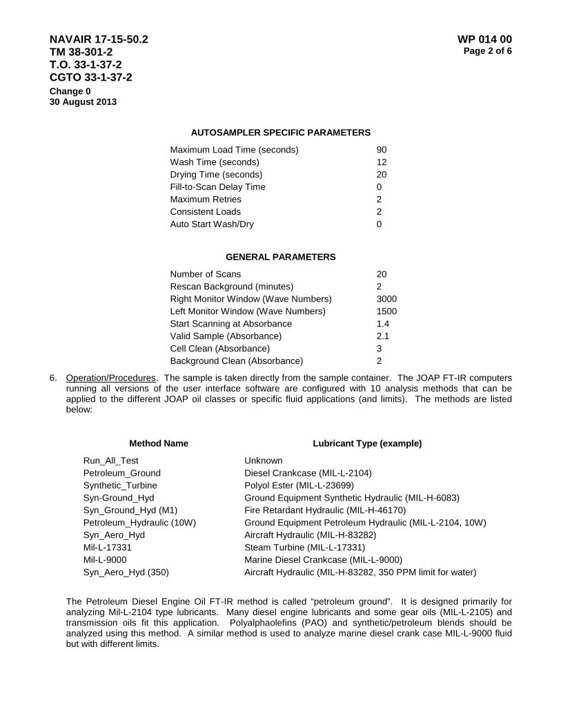
NAVAIR 17-15-50.2 TM 38-301-2 T.O. 33-1-37-2 CGTO 33-1-37-2
WP 014 00 Page 2 of 6
Change 0 30 August 2013
AUTOSAMPLER SPECIFIC PARAMETERS
Maximum Load Time (seconds) 90 Wash Time (seconds) 12 Drying Time (seconds) 20 Fill-to-Scan Delay Time 0 Maximum Retries 2 Consistent Loads 2 Auto Start Wash/Dry 0
GENERAL PARAMETERS
Number of Scans 20 Rescan Background (minutes) 2 Right Monitor Window (Wave Numbers) 3000 Left Monitor Window (Wave Numbers) 1500 Start Scanning at Absorbance 1.4 Valid Sample (Absorbance) 2.1 Cell Clean (Absorbance) 3 Background Clean (Absorbance) 2
6. Operation/Procedures. The sample is taken directly from the sample container. The JOAP FT-IR computers running all versions of the user interface software are configured with 10 analysis methods that can be applied to the different JOAP oil classes or specific fluid applications (and limits). The methods are listed below:
Method Name Lubricant Type (example)
Run_All_Test Unknown Petroleum_Ground Diesel Crankcase (MIL-L-2104) Synthetic_Turbine Polyol Ester (MIL-L-23699) Syn-Ground_Hyd Ground Equipment Synthetic Hydraulic (MIL-H-6083) Syn_Ground_Hyd (M1) Fire Retardant Hydraulic (MIL-H-46170) Petroleum_Hydraulic (10W) Ground Equipment Petroleum Hydraulic (MIL-L-2104, 10W) Syn_Aero_Hyd Aircraft Hydraulic (MIL-H-83282) Mil-L-17331 Steam Turbine (MIL-L-17331) Mil-L-9000 Marine Diesel Crankcase (MIL-L-9000) Syn_Aero_Hyd (350) Aircraft Hydraulic (MIL-H-83282, 350 PPM limit for water)
The Petroleum Diesel Engine Oil FT-IR method is called “petroleum ground”. It is designed primarily for analyzing Mil-L-2104 type lubricants. Many diesel engine lubricants and some gear oils (MIL-L-2105) and transmission oils fit this application. Polyalphaolefins (PAO) and synthetic/petroleum blends should be analyzed using this method. A similar method is used to analyze marine diesel crank case MIL-L-9000 fluid but with different limits.
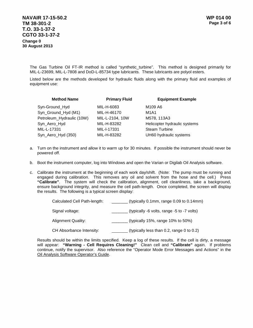
NAVAIR 17-15-50.2 TM 38-301-2 T.O. 33-1-37-2 CGTO 33-1-37-2
WP 014 00 Page 3 of 6
Change 0 30 August 2013
The Gas Turbine Oil FT-IR method is called “synthetic_turbine”. This method is designed primarily for MIL-L-23699, MIL-L-7808 and DoD-L-85734 type lubricants. These lubricants are polyol esters.
Listed below are the methods developed for hydraulic fluids along with the primary fluid and examples of equipment use:
Method Name Primary Fluid Equipment Example
Syn-Ground_Hyd MIL-H-6083 M109 A6 Syn_Ground_Hyd (M1) MIL-H-46170 M1A1 Petroleum_Hydraulic (10W) MIL-L-2104, 10W M578, 113A3 Syn_Aero_Hyd MIL-H-83282 Helicopter hydraulic systems MIL-L-17331 MIL-l-17331 Steam Turbine Syn_Aero_Hyd (350) MIL-H-83282 UH60 hydraulic systems
a. Turn on the instrument and allow it to warm up for 30 minutes. If possible the instrument should never be powered off.
b. Boot the instrument computer, log into Windows and open the Varian or Digilab Oil Analysis software.
c. Calibrate the instrument at the beginning of each work day/shift. (Note: The pump must be running and engaged during calibration. This removes any oil and solvent from the hose and the cell.) Press “Calibrate”. The system will check the calibration, alignment, cell cleanliness, take a background, ensure background integrity, and measure the cell path-length. Once completed, the screen will display the results. The following is a typical screen display:
Calculated Cell Path-length: _______ (typically 0.1mm, range 0.09 to 0.14mm)
Signal voltage: _______ (typically -6 volts, range -5 to -7 volts)
Alignment Quality: _______ (typically 15%, range 10% to 50%)
CH Absorbance Intensity: _______ (typically less than 0.2, range 0 to 0.2)
Results should be within the limits specified. Keep a log of these results. If the cell is dirty, a message will appear: “Warning - Cell Requires Cleaning!” Clean cell and “Calibrate” again. If problems continue, notify the supervisor. Also reference the “Operator Mode Error Messages and Actions” in the Oil Analysis Software Operator’s Guide.
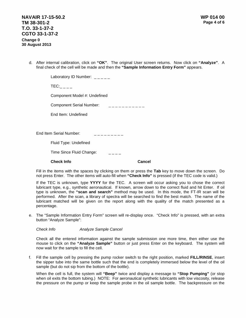
NAVAIR 17-15-50.2 TM 38-301-2 T.O. 33-1-37-2 CGTO 33-1-37-2
WP 014 00 Page 4 of 6
Change 0 30 August 2013
d. After internal calibration, click on “OK”. The original User screen returns. Now click on “Analyze”. A final check of the cell will be made and then the “Sample Information Entry Form” appears.
Laboratory ID Number: _ _ _ _ _
TEC:_ _ _ _
Component Model #: Undefined
Component Serial Number: _ _ _ _ _ _ _ _ _ _ _
End Item: Undefined
End Item Serial Number: _ _ _ _ _ _ _ _ _
Fluid Type: Undefined
Time Since Fluid Change: _ _ _ _
Check Info Cancel
Fill in the items with the spaces by clicking on them or press the Tab key to move down the screen. Do not press Enter. The other items will auto-fill when “Check Info” is pressed (if the TEC code is valid.)
If the TEC is unknown, type YYYY for the TEC. A screen will occur asking you to chose the correct lubricant type, e.g., synthetic aeronautical. If known, arrow down to the correct fluid and hit Enter. If oil type is unknown, the “scan and search” method may be used. In this mode, the FT-IR scan will be performed. After the scan, a library of spectra will be searched to find the best match. The name of the lubricant matched will be given on the report along with the quality of the match presented as a percentage.
e. The “Sample Information Entry Form” screen will re-display once. “Check Info” is pressed, with an extra button “Analyze Sample”:
Check Info Analyze Sample Cancel
Check all the entered information against the sample submission one more time, then either use the mouse to click on the “Analyze Sample” button or just press Enter on the keyboard. The system will now wait for the sample to fill the cell.
f. Fill the sample cell by pressing the pump rocker switch to the right position, marked FILL/RINSE, insert the sipper tube into the same bottle such that the end is completely immersed below the level of the oil sample (but do not sip from the bottom of the bottle).
When the cell is full, the system will “Beep” twice and display a message to “Stop Pumping” (or stop when oil exits the bottom tubing.) NOTE: For aeronautical synthetic lubricants with low viscosity, release the pressure on the pump or keep the sample probe in the oil sample bottle. The backpressure on the

NAVAIR 17-15-50.2 TM 38-301-2 T.O. 33-1-37-2 CGTO 33-1-37-2
WP 014 00 Page 5 of 6
Change 0 30 August 2013
pump will continue to sip the oil through even though the pump is turned off.
g. Allow the FT-IR to collect data. The number of scans will count down in the bottom right hand corner of the screen and the name of the sample will appear at the top of the screen. Once the system has acquired and signal averaged the spectrum, a message “Please Empty Cell” will appear.
h. Press the rocker pump switch to the left “EMPTY” position. Hold the waste beaker under the sample probe. Once the cell is empty, the system will “Beep” twice and the message “Please Clean Cell” will occur.
i. Rinse the sample probe with solvent (from the wash bottle). While still holding the waste beaker below the sample probe catch the waste solvent as you rinse. The waste solvent will later be added to the lab’s waste oil.
j. After the sample probe is washed, press the rocker pump switch to the right, the “FILL/RINSE” position. Clean the cell and hosing by pulling the solvent through the system. Continue rinsing until the solvent exiting the bottom tubing appears clean. Leave the pump running to pull air through the system. The solvent should be exiting into a waste container. NOTE: Viscous fluids, e.g., ground equipment, will clean faster and easier with an air/solvent mixture to “scrub” the walls of the tubing rather than just plain solvent.
k. Observe the display in the bottom left corner of the screen and continue the cleaning process until the displayed absorbance is less than 0.30. The system will continuously check the cell cleanliness. The Oil Analysis software automatically determines the cleanliness of the cell. The system will eventually return to the “Sample Information Entry” screen.
l. Repeat steps f. through k. for additional samples.
m. Shut down the system by clicking the button labeled “Cancel” in the “Sample Information Entry” screen.
n. Release the pressure on the pump tubing to extend the tubing life.
o. Shut off the pump (center position). The screen will go blank after 10 minutes.
p. Do not turn off power to the FT-IR. The heat from the system will assist in keeping the internal KBr beam splitter from fogging and extend the life of the desiccant. The spectrometer should be powered on at all times keeping it warm and stable.
7. Safety Precautions. The solvent, N-heptane, is flammable. Store in a flammable locker and dispose of the oil/solvent waste according to local regulations. (N-heptane is a petroleum distillate.) Gloves and lab coat should be worn, especially for any oil spill cleanup.

NAVAIR 17-15-50.2 TM 38-301-2 T.O. 33-1-37-2 CGTO 33-1-37-2
WP 014 00 Page 6 of 6
Change 0 30 August 2013
This Page is Intentionally Left Blank
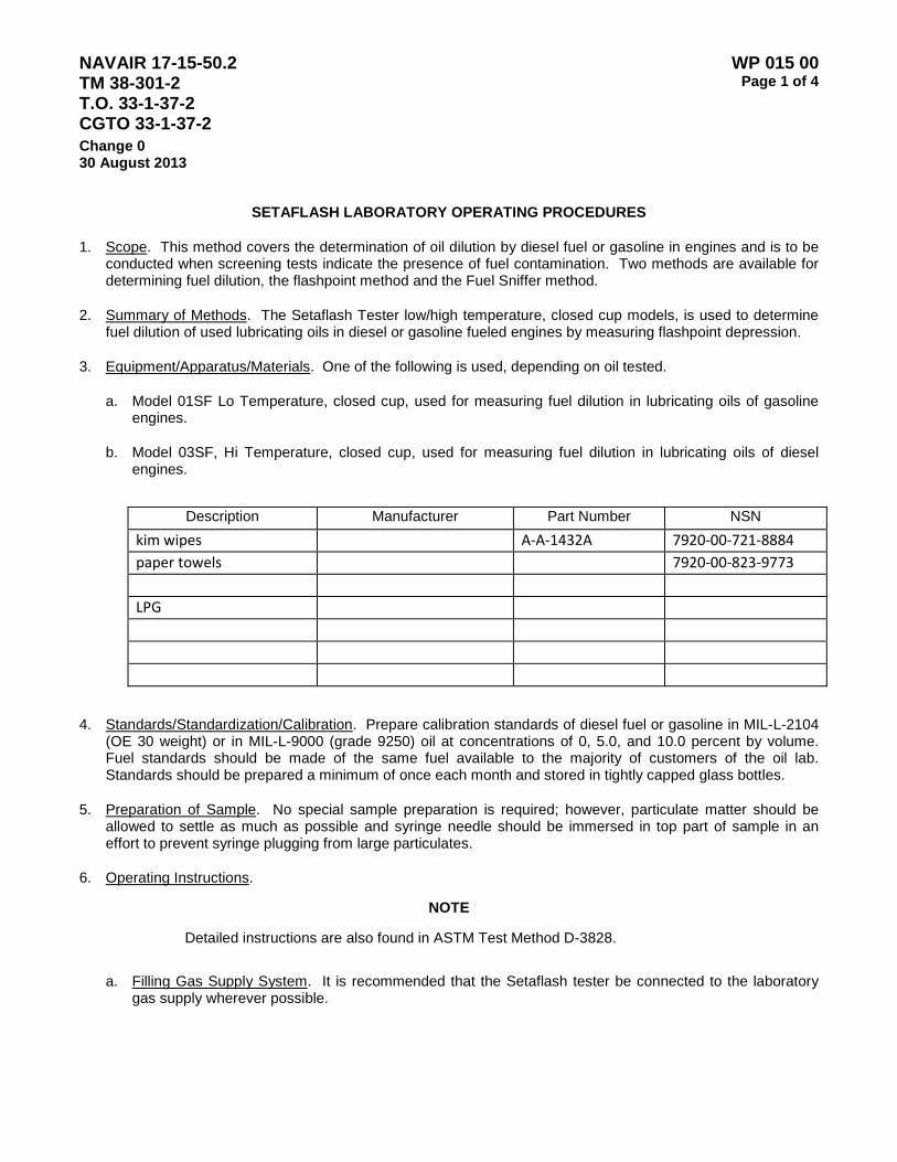
NAVAIR 17-15-50.2 TM 38-301-2 T.O. 33-1-37-2 CGTO 33-1-37-2
WP 015 00 Page 1 of 4
Change 0 30 August 2013
SETAFLASH LABORATORY OPERATING PROCEDURES
1. Scope. This method covers the determination of oil dilution by diesel fuel or gasoline in engines and is to be conducted when screening tests indicate the presence of fuel contamination. Two methods are available for determining fuel dilution, the flashpoint method and the Fuel Sniffer method.
2. Summary of Methods. The Setaflash Tester low/high temperature, closed cup models, is used to determine fuel dilution of used lubricating oils in diesel or gasoline fueled engines by measuring flashpoint depression.
3. Equipment/Apparatus/Materials. One of the following is used, depending on oil tested.
a. Model 01SF Lo Temperature, closed cup, used for measuring fuel dilution in lubricating oils of gasoline engines.
b. Model 03SF, Hi Temperature, closed cup, used for measuring fuel dilution in lubricating oils of diesel engines.
Description Manufacturer Part Number NSN
kim wipes A-A-1432A 7920-00-721-8884 paper towels 7920-00-823-9773 LPG
4. Standards/Standardization/Calibration. Prepare calibration standards of diesel fuel or gasoline in MIL-L-2104
(OE 30 weight) or in MIL-L-9000 (grade 9250) oil at concentrations of 0, 5.0, and 10.0 percent by volume. Fuel standards should be made of the same fuel available to the majority of customers of the oil lab. Standards should be prepared a minimum of once each month and stored in tightly capped glass bottles.
5. Preparation of Sample. No special sample preparation is required; however, particulate matter should be allowed to settle as much as possible and syringe needle should be immersed in top part of sample in an effort to prevent syringe plugging from large particulates.
6. Operating Instructions.
NOTE
Detailed instructions are also found in ASTM Test Method D-3828.
a. Filling Gas Supply System. It is recommended that the Setaflash tester be connected to the laboratory gas supply wherever possible.
NAVAIR 17-15-50.2 TM 38-301-2 T.O. 33-1-37-2 CGTO 33-1-37-2
WP 015 00 Page 2 of 4
Change 0 30 August 2013
SAFETY NOTE
Connection to the laboratory gas supply must NOT be made with flexible tubing. Connect ONLY with stainless steel or copper tubing and permanent attachments.
b. The following applies only when liquefied petroleum gas (LPG) must be used.
(1) Fully charge the tank ONLY when the instrument is at ambient temperature. Do not recharge the tester tank with the pilot test jet lit nor in the vicinity of any ignition source.
CAUTION
The Setaflash Tester contains LPG which may present a safety hazard unless directions are followed explicitly.
(2) Shake the container of LPG to make sure it contains fuel. If empty, it will exhaust the remaining fuel from the Setaflash tester integral tank. Hold the cylinder with the valve nozzle straight down. The valve nozzle requires an adapter that is supplied with the container. Do not twist or bend the nozzle on the cylinder as this may damage its main valve.
(3) Press the nozzle firmly into the valve of the Setaflash integral tank. A hissing sound indicates that fuel is entering the tank.
(4) When the tank is full, a spray-back occurs. Remove the container from the tank valve immediately.
(5) Wipe off excess fuel from the tank or adjacent areas with absorbent paper.
(6) Regular laboratory gas may be used with an adapter - SEE SAFETY NOTE ABOVE.
c. Determination of Flashpoint by FLASH/NO FLASH Method.
(1) Inspect sample well and lid/shutter for cleanliness, and freedom from contamination.
(2) Switch instrument to SUPPLY.
(3) Turn the temperature dial fully clockwise causing the RED signal light to glow.
(4) When the thermometer reads approximately 295 °F (140 °C), slowly return the temperature dial to the point at which the signal light is just extinguished.
(5) The sample well temperature is stable when the signal light slowly cycles ON/OFF. Slight adjustments may be necessary to obtain precise temperature. Numbered divisions are used as a guide to temperature settings.
(6) Charge the syringe with 4 ml of sample, transfer to the filling orifice, taking care not to lose any sample.
(7) Set the timer by rotating the knob clockwise to its fullest extent. DO NOT FORCE AGAINST THE STOP.
NAVAIR 17-15-50.2 TM 38-301-2 T.O. 33-1-37-2 CGTO 33-1-37-2
WP 015 00 Page 3 of 4
Change 0 30 August 2013
(8) Meanwhile, open the gas control valve and light the pilot/test flame. Adjust the test flame size with the pinch valve to match the 4mm dial gauge ring.
(9) When the time has elapsed, slowly and uniformly open and close the slide completely over a period of 2½ seconds - watch for flash at 300 °F (150 °C). Report results as less than or more than 300 °F (150 °C) as applicable.
(10) Close the Gas Control Valve.
(11) To prepare for the next test, unlock the lid and shutter assembly. Lift to hinge stop. Soak up sample with tissues to remove any traces of contamination (if necessary use moistened tissues). Allow the sample well to cool below 212 °F (100 °C) before using moistened tissue. Clean the underside of the lid and filling orifice. A pipe cleaner may be of assistance in cleaning the orifice.
(12) Any further cleaning necessary may be carried out by complete removal of the lid and shutter assembly. To remove this, disconnect the silicon rubber gas tube and slide the assembly to the right. Unscrewing the retaining nut by hand and removing the plunger assembly should also clean the syringe.

NAVAIR 17-15-50.2 TM 38-301-2 T.O. 33-1-37-2 CGTO 33-1-37-2
WP 015 00 Page 4 of 4
Change 0 30 August 2013
This Page is Intentionally Left Blank
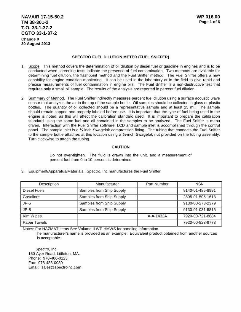
NAVAIR 17-15-50.2 TM 38-301-2 T.O. 33-1-37-2 CGTO 33-1-37-2
WP 016 00 Page 1 of 6
Change 0 30 August 2013
SPECTRO FUEL DILUTION METER (FUEL SNIFFER)
1. Scope. This method covers the determination of oil dilution by diesel fuel or gasoline in engines and is to be conducted when screening tests indicate the presence of fuel contamination. Two methods are available for determining fuel dilution, the flashpoint method and the Fuel Sniffer method. The Fuel Sniffer offers a new capability for engine condition monitoring. It can be used in the laboratory or in the field to give rapid and precise measurements of fuel contamination in engine oils. The Fuel Sniffer is a non-destructive test that requires only a small oil sample. The results of the analysis are reported in percent fuel dilution.
2. Summary of Method. The Fuel Sniffer indirectly measures percent fuel dilution using a surface acoustic wave sensor that analyzes the air in the top of the sample bottle. Oil samples should be collected in glass or plastic bottles. The quantity of oil collected should be a representative sample and at least 25 ml. The sample should remain capped and properly labeled before use. It is important that the type of fuel being used in the engine is noted, as this will affect the calibration standard used. It is important to prepare the calibration standard using the same fuel and oil contained in the samples to be analyzed. The Fuel Sniffer is menu driven. Interaction with the Fuel Sniffer software, LCD and sample inlet is accomplished through the control panel. The sample inlet is a ⅛-inch Swagelok compression fitting. The tubing that connects the Fuel Sniffer to the sample bottle attaches at this location using a ⅛-inch Swagelok nut provided on the tubing assembly. Turn clockwise to attach the tubing.
CAUTION
Do not over-tighten. The fluid is drawn into the unit, and a measurement of percent fuel from 0 to 10 percent is determined.
3. Equipment/Apparatus/Materials. Spectro, Inc manufactures the Fuel Sniffer.
Description Manufacturer Part Number NSN
Diesel Fuels Samples from Ship Supply 9140-01-485-8991 Gasolines Samples from Ship Supply 2805-01-505-1613 JP-5 Samples from Ship Supply 9130-00-273-2379 JP-8 Samples from Ship Supply 9130-01-031-5816 Kim Wipes A-A-1432A 7920-00-721-8884 Paper Towels 7920-00-823-9773 Notes: For HAZMAT items See Volume II WP HMWS for handling information. The manufacturer's name is provided as an example. Equivalent product obtained from another sources
is acceptable.
Spectro, Inc. 160 Ayer Road, Littleton, MA. Phone: 978-486-0123 Fax: 978-486-0030 Email: [email protected]

NAVAIR 17-15-50.2 TM 38-301-2 T.O. 33-1-37-2 CGTO 33-1-37-2
WP 016 00 Page 2 of 6
Change 0 30 August 2013
Spectro, Inc. Fuel Dilution Meter Specifications (Fuel Sniffer):
Dimensions: 9 cm x 20 cm x 28 cm (3.5"x 8" x 11")
Weight: 2.7 Kg (6 pounds)
External Power: 85 to 265 VAC, 47 to 440 Hz
Sensor: SAW Chemical Microprocessor
Display: LCD, with LED backlight
Serial Output: RS232C @ 9600 Baud
Measurement Range: 0 to 10 percent fuel dilution
Measurement Time: 60 seconds
Accuracy: ±0.2 percent
Data Log Memory: 500 measurements
The Fuel Sniffer is designed for general-purpose laboratory use. The Fuel Sniffer is not designed for use
in areas containing explosive atmospheres and should not be operated in these environments. It is recommended that a clean and dedicated circuit be provided in an earth ground configuration to power the Fuel Sniffer. A 110 or 220V power cord is supplied for this purpose.
CAUTION
Always connect the IEC plug into the back of the Fuel Sniffer before plugging into the main power source.
4. Standards and Calibration. Calibration standards may be prepared using any widely available fuel such as gasoline, diesel fuel, JP5 or JP8 mixed in the same type oil as the samples to be analyzed ( for example MIL-L-2104 OE 30 weight, or MIL-L-9000 Grade 9250). The FDM is calibrated at the midpoint of detection which is 5% fuel. Therefore, only one calibration standard is needed which is 5% fuel in oil. NSWCCD procedures require the preparation of an additional 2% standard which is a calibration check for that concentration.
FDM laboratories should have on hand a supply of clear glass, round graduated bottles with PTFE lined lids. The appropriate standard jar volume should be 240ml (8 ounces) and no more than 60% full when prepared according to the following procedure. Standards should be prepared at a minimum of once each month and stored in the same tightly capped glass bottles. NSWCCD procedures require that standards are blended in a glass graduated mixing cylinder with a stopper (at least 100 ml) and then transferred to the glass sample bottle after mixing.
a. Prepare 5 % calibration standard: 1. Label a clean glass sample bottle as “5% FDM Calibration Standard” and include the date.
NAVAIR 17-15-50.2 TM 38-301-2 T.O. 33-1-37-2 CGTO 33-1-37-2
WP 016 00 Page 3 of 6
Change 0 30 August 2013
2. Into a clean graduated glass jar (NSWCCD requires a glass mixing cylinder) pour 50 ml engine oil. 3. Into the same glass bottle (or graduated cylinder) add 5 ml of fuel. 4. Finally add an additional 45 ml of engine oil to the glass bottle (graduated cylinder) making 100 ml
total volume. 5. Tightly cap the bottle (stopper on the graduated cylinder) and gently shake the fuel/oil mixture for at
least 1 minute. 6. For NSWCCD laboratories the mixed standard is transferred to the labeled sample jar.
7. Cap the sample jar and gently swirl for an additional 30 seconds. Set aside for now. 8. Into a another clean graduated mixing cylinder pour 50 ml engine oil. 9. Into the same graduated cylinder add 2 ml of fuel. 10. Finally add an additional 48 ml of engine oil to the graduated cylinder making 100 ml total volume.
11. Place the stopper on the graduated cylinder and gently shake the fuel/oil mixture for 1 minute.
12. Label a clean sample flask as “2% FDM Standard” and include date.
13. Transfer the fuel/oil mixture to a clean sample flask.
14. Cap the sample flask and gently swirl for an additional 30 seconds. Set aside for now. b. Calibration:
1. Rest the 5% sample flask on a level surface and remove the cap.
WARNING
The oil sample bottle should be 125 milliliters approximately ¾ full. Do not fill the sample bottle to the top. There must be a headspace between the sample and the top of the bottle for a proper measurement and to avoid the possibility of contaminating and damaging the Fuel Sniffer’s sensor with the sample.
NOTE
To ensure a representative calibration sample, the standard should be mixed and allowed to equilibrate for at least one hour for diesel fuel and at least four hours for more volatile gasoline fuel or jet fuel.
CAUTION
Using a standard immediately after preparation will cause the instrument to under report values.
The flask should remain uncapped during the equilibration period to ensure a representative calibration sample. This is done to “off gas” the light end hydrocarbons that are present in fresh fuel samples. This is consistent with an actual engine oil sample, since it would have been exposed to heat during operation that drives off the light end gases. Hence using a standard immediately after preparation will cause the instrument to under report actual measured values because the light end gases have been included in the

NAVAIR 17-15-50.2 TM 38-301-2 T.O. 33-1-37-2 CGTO 33-1-37-2
WP 016 00 Page 4 of 6
Change 0 30 August 2013
standard calibration. The following sequences of LCD screens illustrate the calibrate fuel dilution mode. The sample bottle clamp and seal must be connected by way of the sample tube to the “Sample Connect” before starting a measurement. By pressing the start button, the analysis cycle will begin, and the red calibrate LED will illuminate.
2. Perform the Calibration steps required by the instrument.
CALIBRATE FUEL DILUTION PRESS START OR ⇓⇑
CALIBRATE FUEL DILUTION CALIB, IN PROGRESS, WAIT
CALIBRATION SATISFACTORY PRESS SELECT TO CONTINUE
Upon a successful calibration, the calibrate LED will turn off and the user must press “Select” to return to the main menu choices.
5. Sample Preparation. No special sample preparation is required; however, particulate matter should be allowed to settle as much as possible and syringe needle should be immersed in top part of sample in an effort to prevent syringe plugging from large particulates.
6. Operation/Procedures. Basic operation is covered here. Please refer to the manufacturer’s manual for more detailed information concerning theory of operation, accessories, data transfer, parts, maintenance, and troubleshooting.
a. Software Overview. The Fuel Sniffer is a menu driven instrument. The LCD display presents a series of menus, which allow operation of the instrument. The software prompts the user through each step to make a successful measurement analysis. There are four pushbuttons on the front panel, “Select”, “Down Arrow”, “Up Arrow”, and “Start” which are used to input information. Each menu function is discussed in detail.
b. Start-Up Screens. Upon power up, the LCD will indicate the following displays:
MICROSENSOR SYSTEMS INC. FDM METER VERSION 3.1.5
AUTOTEST UNDERWAY PLEASE WAIT
AUTOTEST SATISFACTORY PRESS SELECT TO CONTINUE
Upon successful completion of the power-up, the Fuel Sniffer will respond with a series of five tones and the front panel LED’S will each flash from top left to bottom right sequence with each audible tone. By pressing the “Select” button, the Fuel Sniffer will respond with the following main operating menu.
PROGRAM SELECTION PRESS ⇓⇑ FOR MENU
By pressing either “arrow” button, the Fuel Sniffer will display the menu selections. The primary Fuel Sniffer menus are below.
MEASURE FUEL DILUTION PRESS START OR ⇓⇑
CALIBRATE FUEL DILUTION PRESS START OR ⇓⇑
TRANSFER DATA TO OUTPUT PRESS START OR ⇓⇑

NAVAIR 17-15-50.2 TM 38-301-2 T.O. 33-1-37-2 CGTO 33-1-37-2
WP 016 00 Page 5 of 6
Change 0 30 August 2013
SET TIME AND DATE PRESS START OR ⇓⇑
c. Measuring Fuel Dilution.
(1) Basic Information. This mode allows the measurement of fuel dilution in oil samples. The results are reported in percent fuel dilution on the LCD. Each sample analysis requires 60 seconds to complete. The Fuel Sniffer must be in position on its stand with the sample inlet tubing connected to the tubing connector on the control panel. The Fuel Sniffer should be allowed to warm up and stabilize for at least 15 minutes after the power On/Off toggle switch has been turned to On.
(2) Procedure. Loosen the two screws that hold the sample bottle diameter adjustment bar and reposition so that the sample bottle is centered on the platform. Tighten the screws to hold the bar in position. Set the sample platform to the correct height by loosening the two captive adjustment screws. Set the table so that the sample bottle just clears the bottom of the sample cover with the sample bottle lever in the up position (towards the Fuel Sniffer). Tighten the adjustment screws. Place the sample bottle in position on the sample table. Move the sample bottle lever into the down (towards the operator) position. There should be some resistance as the lever is moved into the down position such that the sample bottle will be locked in place.
(3) Analysis Start. By pressing the start button, the analysis cycle will begin and the green measure LED will illuminate. The Fuel Sniffer will begin a pumping sequence to first purge the headspace, then reverse flow pulling the headspace sample into the detector and then reversing the flow purging the detector expelling the sample in preparation for the next measurement.
(4) Results. The results will be reported in percent fuel dilution over the calibrated range of 0 to 10 percent. The user must acknowledge the result and push “Select” to begin the next measurement cycle. The following sequences of LCD screens illustrate the measure fuel dilution mode.
MEASURE FUEL DILUTION PRESS START OR ⇓⇑
MEASURE FUEL DILUTION MEAS. IN PROGRESS, WAIT
0.0% FUEL DILUTION PRESS SELECT TO CONTINUE
MEASURE FUEL DILUTION PRESS START OR ⇓⇑
Please refer to the complete Spectro, Inc. “System Description and Operations Manual” which comes with each unit
.

NAVAIR 17-15-50.2 TM 38-301-2 T.O. 33-1-37-2 CGTO 33-1-37-2
WP 016 00 Page 6 of 6
Change 0 30 August 2013
This Page Intentionally Left Blank
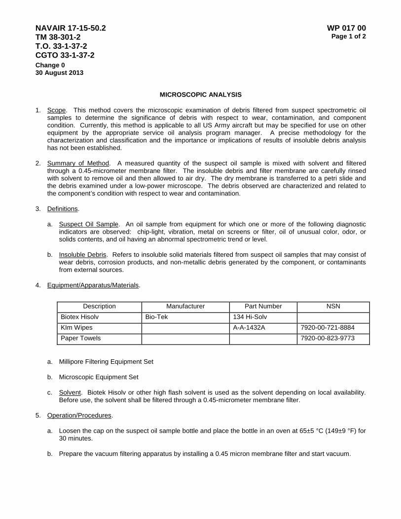
NAVAIR 17-15-50.2 TM 38-301-2 T.O. 33-1-37-2 CGTO 33-1-37-2
WP 017 00 Page 1 of 2
Change 0 30 August 2013
MICROSCOPIC ANALYSIS
1. Scope. This method covers the microscopic examination of debris filtered from suspect spectrometric oil samples to determine the significance of debris with respect to wear, contamination, and component condition. Currently, this method is applicable to all US Army aircraft but may be specified for use on other equipment by the appropriate service oil analysis program manager. A precise methodology for the characterization and classification and the importance or implications of results of insoluble debris analysis has not been established.
2. Summary of Method. A measured quantity of the suspect oil sample is mixed with solvent and filtered through a 0.45-micrometer membrane filter. The insoluble debris and filter membrane are carefully rinsed with solvent to remove oil and then allowed to air dry. The dry membrane is transferred to a petri slide and the debris examined under a low-power microscope. The debris observed are characterized and related to the component’s condition with respect to wear and contamination.
3. Definitions.
a. Suspect Oil Sample. An oil sample from equipment for which one or more of the following diagnostic indicators are observed: chip-light, vibration, metal on screens or filter, oil of unusual color, odor, or solids contents, and oil having an abnormal spectrometric trend or level.
b. Insoluble Debris. Refers to insoluble solid materials filtered from suspect oil samples that may consist of wear debris, corrosion products, and non-metallic debris generated by the component, or contaminants from external sources.
4. Equipment/Apparatus/Materials.
Description Manufacturer Part Number NSN
Biotex Hisolv Bio-Tek 134 Hi-Solv KIm Wipes A-A-1432A 7920-00-721-8884 Paper Towels 7920-00-823-9773
a. Millipore Filtering Equipment Set
b. Microscopic Equipment Set
c. Solvent. Biotek Hisolv or other high flash solvent is used as the solvent depending on local availability. Before use, the solvent shall be filtered through a 0.45-micrometer membrane filter.
5. Operation/Procedures.
a. Loosen the cap on the suspect oil sample bottle and place the bottle in an oven at 65±5 °C (149±9 °F) for 30 minutes.
b. Prepare the vacuum filtering apparatus by installing a 0.45 micron membrane filter and start vacuum.
NAVAIR 17-15-50.2 TM 38-301-2 T.O. 33-1-37-2 CGTO 33-1-37-2
WP 017 00 Page 2 of 2
Change 0 30 August 2013
c. Remove the warm sample from the oven, tightly cap, and shake vigorously. Pour 10 ml of the sample into a 100 ml graduated cylinder with a stopper. Add 90 ml of pre-filtered solvent, install stopper and mix well.
d. With the vacuum still applied, carefully remove the spring clamp and upper section of the filter funnel carefully wash the edges of the filter membrane with a gentle stream of solvent using care not to wash debris off the filter membrane. Continue wash until membrane and debris are free of oil. Allow the membrane to dry. Transfer the membrane to a petri slide.
e. Inspect the debris using the microscope, identify the metal or alloy and record the findings.

NAVAIR 17-15-50.2 TM 38-301-2 T.O. 33-1-37-2 CGTO 33-1-37-2
WP 018 00 Page 1 of 2
Change 0 30 August 2013
PARTICLE COUNTER TEST
1. Scope. This work package provides references to the operating manuals used to perform particle counting tests
2. Particle Counter Operating Manuals. Table 2 provides a list of the appropriate operating manuals to use depending on the particle counter being used.
4. Equipment/Supplies. See Table 1.
Table 1 – Equipment/Supplies
Description Manufacturer Part Number NSN kim wipes A-A-1432A 7920-00-721-8884 paper towels 7920-00-823-9773 PODS HIAC Ultrasonic Bath HIAC 690-500-0100
Table 2 – Particle Counter Operating Manuals
Particle Counting System Applicable Manual
HIAC/ROYCO 8011-3 NAVAIR 17-15-521 - Operation Intermediate Maintenance Instructions for Particle Counting System, Part Number 8011-3
PODS Type I (OBVY1)
Part number 2087323-01
NAVAIR 17-15BF-97 – Operating Instructions for Hydraulic Particle Counter
PODS Type II (OBVY1)
Part number 2087323-02
NAVAIR 17-15BF-97 – Operating Instructions for Hydraulic Particle Counter
Note: NAVAIR Manuals are available on the NATEC Technical Data Website: https://mynatec.navair.navy.mil/

NAVAIR 17-15-50.2 TM 38-301-2 T.O. 33-1-37-2 CGTO 33-1-37-2
WP 018 00 Page 2 of 2
Change 0 30 August 2013
This Page Intentionally Left Blank

NAVAIR 17-15-50.2 TM 38-301-2 T.O. 33-1-37-2 CGTO 33-1-37-2
WP 019 00 Page 1 of 20
Change 0 30 August 2013
US AIR FORCE B-2 COOLANT TESTING PROCEDURES
Table of Contents
Page
1. Introduction....................................................................................................................................................... 1 2. General. .......................................................................................................................................................... 1 3. Equipment. ..................................................................................................................................................... 2 4. Test Sequence. ................................................................................................................................................ 2 5. Laboratory Safety. ............................................................................................................................................ 2 6. Appearance Test. ............................................................................................................................................. 3 7. Dielectric Strength. ........................................................................................................................................... 3 8. Particulate Contamination. ............................................................................................................................... 6 9. Volume Resistivity. ........................................................................................................................................ 10 10. Water Content. .............................................................................................................................................. 13
1. Introduction. This section defines the procedures, requirements, equipment and material needed for sampling and testing Silicate Ester-Based Dielectric (SEBD) coolant fluid used in operating systems such as radar cooling in the Environmental Control System of the B-2 Bomber.
2. General.
a. The equipment cooling system of the B-2 aircraft incorporates three liquid cooling subsystems and five circulated air subsystems. The liquid cooling subsystems consist of the Ethylene Glycol-Water Subsystem (EGW), DMS/LC Subsystem and the Liquid Cooling Subsystem (LCS).
b. The Liquid Cooling Subsystem (LCS) is composed of two independent closed cooling loops located in the left-hand and right-hand forward center section of the aircraft. The left side LCS loop (normally the transmitting radar side) is identical to the right side LCS loop (normally in standby). Each closed loop circulates liquid coolant through each of the radar packages to maintain the components at a controlled temperature. The fluid is then circulated through a three-fluid (coolant-EGW) heat exchanger for heat dissipation via the EGW coolant loop to the sink heat exchanger.
c. Each loop supplies liquid coolant at a flow rate of 4.0 GPM to the liquid cooling passages of 55.0 degrees Fahrenheit and a maximum pressure of 175.0 psig. The maximum volume of fluid in each loop is 4.76 gallons.
d. The LCS transports heat from both radar transmitters and antennas. The transmitters require a heat transport fluid with both high dielectric properties and thermal transport characteristics. The heat transfer fluid is a silicate ester-based dielectric (SEBD) coolant fluid, Coolanol 25R or Flocool 180.
e. As the fluid cycles throughout the aluminum system lines, metal particles may be generated by the relative motion between metallic parts within the mechanical system. Friction and continuous wearing away of contacting surfaces will increase the amount of particulate contamination. As particulate size and quantity
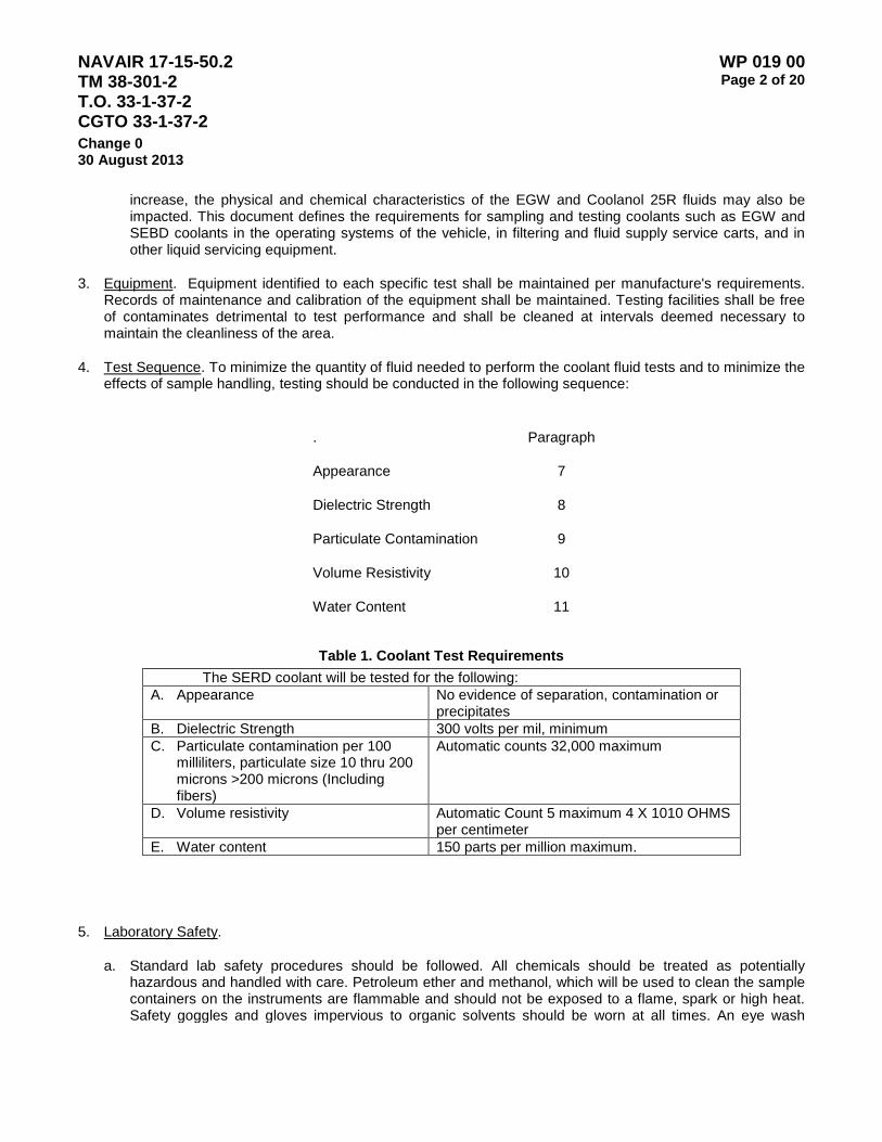
NAVAIR 17-15-50.2 TM 38-301-2 T.O. 33-1-37-2 CGTO 33-1-37-2
WP 019 00 Page 2 of 20
Change 0 30 August 2013
increase, the physical and chemical characteristics of the EGW and Coolanol 25R fluids may also be impacted. This document defines the requirements for sampling and testing coolants such as EGW and SEBD coolants in the operating systems of the vehicle, in filtering and fluid supply service carts, and in other liquid servicing equipment.
3. Equipment. Equipment identified to each specific test shall be maintained per manufacture's requirements. Records of maintenance and calibration of the equipment shall be maintained. Testing facilities shall be free of contaminates detrimental to test performance and shall be cleaned at intervals deemed necessary to maintain the cleanliness of the area.
4. Test Sequence. To minimize the quantity of fluid needed to perform the coolant fluid tests and to minimize the effects of sample handling, testing should be conducted in the following sequence:
. Paragraph
Appearance 7
Dielectric Strength 8
Particulate Contamination 9
Volume Resistivity 10
Water Content 11
Table 1. Coolant Test Requirements
The SERD coolant will be tested for the following: A. Appearance No evidence of separation, contamination or
precipitates B. Dielectric Strength 300 volts per mil, minimum C. Particulate contamination per 100
milliliters, particulate size 10 thru 200 microns >200 microns (Including fibers)
Automatic counts 32,000 maximum
D. Volume resistivity Automatic Count 5 maximum 4 X 10¹⁰ OHMS per centimeter
E. Water content 150 parts per million maximum.
5. Laboratory Safety.
a. Standard lab safety procedures should be followed. All chemicals should be treated as potentially hazardous and handled with care. Petroleum ether and methanol, which will be used to clean the sample containers on the instruments are flammable and should not be exposed to a flame, spark or high heat. Safety goggles and gloves impervious to organic solvents should be worn at all times. An eye wash

NAVAIR 17-15-50.2 TM 38-301-2 T.O. 33-1-37-2 CGTO 33-1-37-2
WP 019 00 Page 3 of 20
Change 0 30 August 2013
station, fire blanket and fire extinguisher should be readily accessible at all times. Material Safety Data Sheets (MSDS) for all chemicals should be accessible to lab personnel while working in the lab. Never work in the lab alone-ensure there is someone else within easy calling distance.
b. Waste chemicals should be disposed of in approved marked waste containers. While the waste organic chemicals used in these procedures may be mixed in a single waste container, it may be more convenient to use one container for SEBD waste chemicals and another for EGW wastes. Remove waste chemicals from the lab on a regular basis.
6. Appearance Test.
a. Prior to the sample analysis, the unopened sample bottle shall be visually inspected for proper filling and sealing, as well as evidence of gross contamination. Properly filled bottles will be almost completely filled with fluid extending up to the bottom of the threaded neck section. The purpose of completely filling the bottle is to minimize the quantity of air present, which could contain large amounts of atmospheric moisture, and to assure that adequate fluid is available to perform all of the required tests. Activities submitting SEBD coolant samples in improper or inadequately filled bottles shall be advised to resample the equipment.
b. Gross particulate contamination, i.e., particles large enough to be seen with the unaided eye, will also be most visible when the fluid is allowed to stand motionless for a period of time. Like free water, such particles will generally settle to the bottom of the bottle. Gross particulate contamination is usually indicative of improper sampling technique. If either is suspected, the submitting activity shall be advised and requested to resample the equipment.
c. Fluid turbidity results in the SEBD fluid appearing cloudy as opposed to its normal clear, transparent appearance. Turbidity is most visible when the fluid is agitated and may be indicative of large amounts of air, free water or suspended foreign matter..
Allowing the fluid to stand stationary for a period of time will assist in identifying the probable cause. Turbidity caused by suspended semi-solid matter is of particular concern as it may be indicative of chemical degradation of the SEBD fluid. The contamination by-products of such degradation will also show up when performing the test for particulate contamination
d. Prior to sample analysis, fluid in the sample bottle shall be visually inspected for evidence of free water, turbidity or visible particles. This inspection is somewhat limited by translucent plastic bottles but can be remedied by using a glass bottle or positioning the plastic bottle in front of a strong light source. Free water when present, will collect in the bottom of the bottle and be readily visible. Allowing the bottle to stand stationary for at least 10 minutes prior to the inspection will cause any dispersed water droplets to settle out, rendering them more visible. Free water is cause for rejection and the submitting activity shall be requested to resample the equipment to confirm this indication.
7. Dielectric Strength.
a. Introduction. This procedure describes the method for performing dielectric strength of silicate ester base dielectric coolant fluid with the Hipotronics Model 0C60D, digital Oil Dielectric Test Set. All personnel should review the manufacture's instruction manual prior to using the equipment.
b. Equipment and Materials. Model 0C60D Oil Dielectric Test Set, Hipotronics Inc.
c. Equipment Information and Test Procedures. The referenced test set provides the means of applying, measuring, and displaying the value of the voltage required to electrically stress insulating liquids such as SEBD to a point where the insulating qualities break down and allow an electrical current to flow between

NAVAIR 17-15-50.2 TM 38-301-2 T.O. 33-1-37-2 CGTO 33-1-37-2
WP 019 00 Page 4 of 20
Change 0 30 August 2013
and electrodes applying the voltage. The 0C60D is capable of applying 0 to 60,000 VAC between two electrodes that are spaced 2.5mm or 0.10 inches apart in a test cup that holds the test sample.
NOTE
During testing a safety cover is lowered to protect the test operator. The rate of applied voltage is determined by selecting the 3000 VPS (volts per second) setting on control panel energized by a facility power source of 115 VAC, 50/60 HZ. The breakdown voltage for SEBD is 300 volts per mil (minimum) and will require the test sample to be subjected to 30 kilovolts minimum to be considered sufficiently free of contaminating agents.
Specifications
Test Voltage: 0 to 60 kilo volts AC (50,000 VAC)
Power Rating: 115 VAC, 50/60 HZ, 15 amps
(1) Set-Up Procedures.
(a) Remove packing material, power cord, test cells, and any other components from the test cage.
(b) GROUND THE UNIT BEFORE CONNECTING INPUT POWER. The ground lug is located on the left side of the unit, below the plug receptacles.
(c) Insert the socket end of the power cord into the receptacle on the left side of the unit and connect it to a suitable power source. IF A TWO-PRONG ADAPTER IS USED, BE SURE TO GROUND THE PIGTAIL.
(2) Operating Procedures.
(a) ENSURE THAT THE UNIT IS PROPERLY GROUNDED BEFORE CONNECTING INPUT POWER. The ground lug is located on the left side of the unit, below the plug receptacle.
(b) Ensure that the power cord is properly plugged in as described in step c of the SET-UP PROCEDURE.
(c) Check and adjust the spacing of electrodes in the test cell using a 100 mil gage shim. Push electrodes tightly against gage shim. The distance between the two electrodes will be 100 mils (0.1 inches).
NOTE
Do not fill test receptacle inside test chamber.
(d) Fill the test cell with sufficient insulating liquid to completely cover the electrodes.
(e) Swirl the insulating liquid by rocking the test cell slowly. (Rapid agitation may create an excess of air bubbles in the liquid).
NAVAIR 17-15-50.2 TM 38-301-2 T.O. 33-1-37-2 CGTO 33-1-37-2
WP 019 00 Page 5 of 20
Change 0 30 August 2013
(f) Gently snap the filled test cell in place between the bushing(s) of the transformer and the test cage and close the safety glass cover.
(g) Before testing, allow the sample to stand for a minimum of three minutes to permit any accumulated air bubbles to escape. If a VDE test cell is used, plug the line cord into the receptacle on the left panel of the test cage.
(h) Turn the AC power switch ON.
(i) If the failure indicator lights, press the reset push-button until the voltmeter reading is zero.
(j) With the voltmeter reading zero, set the rate/rise rotary selector to 3000 VPS.
(k) Press the START push-button to activate the output voltage. Voltage is applied automatically at the specified rate until breakdown occurs, at which point the FAILURE indicator lights and the voltage is turned off.
NOTE
The voltage may be terminated before breakdown by releasing the test cage interlock switch (HV OFF ANYTIME). This is accomplished by opening the safety glass cover. Also, voltage may be maintained at any level prior to breakdown by setting the RATE/RISE selector to STOP (manual dwell).
(l) The voltmeter continues to display the breakdown voltage until the reset pushbutton is pressed. After reading and recording breakdown voltage, press the RESET push-button and allow the voltmeter to return to zero.
NOTE
Clean test cell between each test with methanol.
(m) Perform three (3) breakdown tests beginning with step k. If results are within + 10% of the average of the sample taken, test is complete. If results are not within + 10%, perform two additional tests. Discard the two- (2) high/low samples and average the remaining three (3) sample results. If results are within + 10% of the average, the test is complete. Five breakdowns may be performed on one cup filling with one-minute interval between breakdowns.
NOTE
Minimum instrument reading shall be 30 kv which is equivalent to the dielectric strength of 300 volts/mil using the prescribed sample volume.
(3) Calculations. Dielectric strength = volts/mil (volts/100mil).
NOTE
"mil" refers to gap between electrodes.
NAVAIR 17-15-50.2 TM 38-301-2 T.O. 33-1-37-2 CGTO 33-1-37-2
WP 019 00 Page 6 of 20
Change 0 30 August 2013
8. Particulate Contamination.
a. Introduction. This procedure describes how to perform the counting of particles suspended in SEBD using the Hiac/Royco Model 800A Particle Counter.
b. Equipment and Materials.
Model 8000A Hiac/Royco, Particle Counter with Printer
Automatic Bottle Sampler unit (ABS)
Methonol or Isopropanol (filter the solution through a 0.45 micron filter)
Petroleum Ether (reagent grade)
c. Equipment Information. The referenced particle counting system is comprised of several individual components. A counter, an automatic bottle sampler, and a sensor. Descriptions of each of the components are given below:
(1) The counter is equipped with a keypad, a 40 column 16-line liquid crystal display (LCD), and an internal 40 character per line graphics printer. Although wide ranges of contamination standards are resident in the unit, the operator has the option of storing a different standard, which better describes the desired application. Any of the standards can then be selected with a single keyboard entry. The Model 8000A is capable of acquiring count data for eight particle size ranges. The calibration graph for the sensor being utilized shows the actual values that must be input to the counter to set the size range limits for the test. Whenever a different size range is desired or when a different sensor is utilized the corresponding graph must be entered into the counter. The manufacturer supplies the calibration graph and the counter is calibrated every 5 months. Before a test can be run, the operator must input the number of sample runs to be performed. The counter automatically gives results for each sample data run as well as the average of the selected number of runs. The operator must also input the limit for the counter's audible alarm. After the test has been performed, the results can be displayed in either tabular or histogram format, and a hard copy can be obtained from the printer.
(2) The automatic bottle sample is a Hiac/Royco model ABS sampler (P/N BS-13). The sampler is comprised of three components: A sample holder, a volume measuring tube, and a control box. The sample to be analyzed is placed in a container inside the sample holder. This sample holder has a pressure rating of 60 PSI and is equipped with a magnetic stirrer, which keeps the sample particles in a uniform suspension. Positive pressure is then used to transfer the sample, at a constant flow rate, from the sample holder through the sensor (which will be discussed later) to the volume measuring tube. The pressure required for this transfer can be provided by either a facility air supply or by a separate pump. The sampler is equipped with a locking regulator to regulate the supply pressure down to the desired 5 to 60 PSI. Once the sample has passed through the sensor, it goes into the volume measuring tube. This tube is equipped with two moveable light sensors, which generate the "start count" and "stop count" signals to the counter. The volume of sample to be analyzed is determined by the positioning of these two light blocks. Upon completion of a test, the volume measuring tube is drained by means of an automatic valve and drain line.
(3) A ac/Royco mode HRLD-400 sensor (P/N 040 x 300-1) is provided with the particle counting system. This sensor, which detects particles in the sample by means of the
NAVAIR 17-15-50.2 TM 38-301-2 T.O. 33-1-37-2 CGTO 33-1-37-2
WP 019 00 Page 7 of 20
Change 0 30 August 2013
light obscuration method, has the following specifications:
(a) Measurement Range: 2 - 400 microns
(b) Recommended Concentration Limit: 8,000 particles/ml
(c) Flow Rate: 10 - 200 ml/Min
(d) Pressure Limit: 1000 psi
(e) Temperature Limit:: 150 degrees Fahrenheit
(f) Frequency Response: To 250 kHz
(g) Precision: Coefficient of variation less than 1% for mean mounts greater than 1000 particles per ml.
(h) Accuracy: Traceable to NIST Standard Reference Materials.
(4) As mentioned previously, a calibration curve is provided with the sensor so that the operator can key the desired size range limits into the Model 8000A Counter. This sensor will be calibrated with glass spheres in oil or water with latex spheres (use the values from the curve).
d. Test Procedures.
(1) Turn on the particle counter and the automatic bottle sampler.
(2) Press any key on the key pad to access the main function menu.
(3) Place a container of the sample to be analyzed into the sample holder. Put a clean stirring rod into the container and turn the sample holder's magnetic stirrer on.
NOTE
Be extremely careful that the stir bar is "just" moving to eliminate the counting of bubbles as particles.
If a vortex appears in the center of the liquid, it is being stirred too rapidly. Adjust stir speed until vortex is no longer visible.
(4) Position the volume measuring tube light blocks. The volume of sample that is analyzed is determined by the positioning of these two blocks. Volume should be set for a 100 ml sample size.
(5) Set the locking regulator on the sample holder to the desired pressure. Desire pressure will provide a flow rate of 20 ml in 20 seconds, ≈ 14-20 PSI.
(6) Press start key.
(7) Once the test is complete obtain results from the display and/or printer.
(8) First flush the system with a total of 60 ml of Petroleum Ether, followed by flush with 120 ml of menthanol.
(9) Turn off the particle counter and automatic bottle sampler.
NOTE
NAVAIR 17-15-50.2 TM 38-301-2 T.O. 33-1-37-2 CGTO 33-1-37-2
WP 019 00 Page 8 of 20
Change 0 30 August 2013
If initial set-up data is lost, reenter data using the following calibration procedures.
e. Calibration Procedures.
(1) Turn unit on and press any key.
(2) Press the more key on the main function menu.
(3) Press the user STD key.
(4) Press the alter STD key.
(5) Enter the following data:
(a) Standard Name: Latex
(b) Number of Classes: 16
(c) Coml/Diff: Cumulative
(d) Class Limit Units: Counts
(e) Sample Volume: 20.00 ml
(f) Classify: Runs only
(g) Number of Channels: 3
(h) Class 1 thru 16: N/A
(i) Channel 1: 10
(j) Channel 2: 200
(k) Channel 3: 400
(6) Press exit key.
(7) Save standard in storage slot #1.
(8) Using exit key return to main menu.
(9) From the main menu, press Set-up.
(10) Press the global set-up key and enter the following data:
(a) Operator ID: Operators Initials
(b) Number of Runs: 3
(c) Delete Time: 00H, 00M, 10S
(d) Delay Time: 00H, 00M, 00S
(e) Transducer Units: English
(f) Quick-Adjust-Rate: 02H, 30M
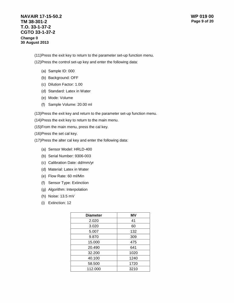
NAVAIR 17-15-50.2 TM 38-301-2 T.O. 33-1-37-2 CGTO 33-1-37-2
WP 019 00 Page 9 of 20
Change 0 30 August 2013
(11) Press the exit key to return to the parameter set-up function menu.
(12) Press the control set-up key and enter the following data:
(a) Sample ID: 000
(b) Background: OFF
(c) Dilution Factor: 1.00
(d) Standard: Latex in Water
(e) Mode: Volume
(f) Sample Volume: 20.00 ml
(13) Press the exit key and return to the parameter set-up function menu.
(14) Press the exit key to return to the main menu.
(15) From the main menu, press the cal key.
(16) Press the set cal key.
(17) Press the alter cal key and enter the following data:
(a) Sensor Model: HRLD-400
(b) Serial Number: 9306-003
(c) Calibration Date: dd/mm/yr
(d) Material: Latex in Water
(e) Flow Rate: 60 ml/Min
(f) Sensor Type: Extinction
(g) Algorithm: Interpolation
(h) Noise: 13.5 mV
(i) Extinction: 12
Diameter MV
2.020 41 3.020 60 5.007 132 9.870 309 15.000 475 20.490 641 32.200 1020 40.100 1240 58.500 1720 112.000 3210
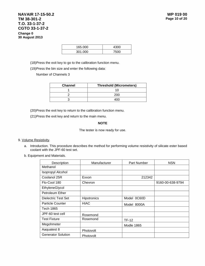
NAVAIR 17-15-50.2 TM 38-301-2 T.O. 33-1-37-2 CGTO 33-1-37-2
WP 019 00 Page 10 of 20
Change 0 30 August 2013
165.000 4300 301.000 7500
(18) Press the exit key to go to the calibration function menu.
(19) Press the bin size and enter the following data:
Number of Channels 3
Channel Threshold (Micrometers)
1 10 2 200 3 400
(20) Press the exit key to return to the calibration function menu.
(21) Press the exit key and return to the main menu.
NOTE
The tester is now ready for use.
9. Volume Resistivity.
a. Introduction. This procedure describes the method for performing volume resistivity of silicate ester based coolant with the JPF-60 test set.
b. Equipment and Materials.
Description Manufacturer Part Number NSN Methanol Isopropyl Alcohol Coolanol 25R Exxon 212342 Flo-Cool 180 Chevron 9160-00-638-9794 EthyleneGlycol Petroleum Ether Dielectric Test Set Hipotronics Model 0C60D Particle Counter HIAC Model 8000A Tech 1865 JPF-60 test cell Rosemond Test Fixture Rosemond TF-12 Megohmeter Modle 1865 Aaquatest 8 Photovolt Generator Solution Photovolt
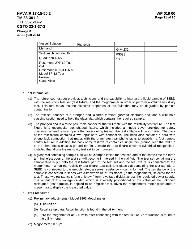
NAVAIR 17-15-50.2 TM 38-301-2 T.O. 33-1-37-2 CGTO 33-1-37-2
WP 019 00 Page 11 of 20
Change 0 30 August 2013
Vessel Solution Photovolt Methanol O-M-232 Sodium Hydroxide, 1N 0S598 QuadTech 1865
1865
Rosemond JPF-60 Test Cell
Rosemond (PN JPF-60) Model TF-12 Test Fixture
Glass Vials
c. Test Information.
(1) The referenced test set provides technicians and the capability to interface a liquid sample of SEBD with the resistivity test set (test fixture) and the megohmeter in order to perform a volume resistivity test. This test measures the dielectric properties of the fluid that may be degraded by particle contamination.
(2) The test set consists of a pronged end, a three terminal guarded electrode end, and a wire bale clasping section used to hold the glass vial, which contains the required sample.
(3) The pronged end is a three pole male connector that will mate with the resistivity test fixture. The test fixture is a rectangular box shaped fixture, which includes a hinged cover provided for safety concerns. When the user opens the cover during testing, the test voltage will be curtailed. The back of the test fixture contains a two input hard wire connection. The back also contains a hard wire phone jack connection that mates with the ohmmeter rear phone jacks to establish a foot remote control feature. In addition, the back of the test fixture contains a single thin (ground) lead that will run to the ohmmeter's chassis ground terminal. Inside the test fixture cover, a cylindrical receptacle is installed that allows the resistivity test set to be mounted.
(4) A glass vial containing sample fluid will be clamped inside the test set, and at the same time the three terminal electrodes of the test set will become immersed in the vial fluid. The test set containing the sample fluid is put onto the test fixture part of the test set and the test fixture is connected to the megohmeter. When the resistivity test fixture, test cell, and glass vial containing the test sample of SEBD is connected to the megohmeter, a series resistance circuit is formed. The resistance of the sample is connected in series with a known value of resistance (in the megohmeter) selected for the test. These two resistance's (one unknown) form a voltage divider across the regulated power supply. The output of this voltage divider, which is inversely proportional to the value of the unknown resistance (test sample), is applied to an amplifier that drives the megohmeter meter (calibrated in megohms) to display the measured value.
d. Test Procedures.
(1) Preliminary adjustments - Model 1865 Megohmeter
(a) Turn unit on.
(b) Recall setup data. Recall function is found in the utility menu.
(c) Zero the megohmeter at 500 volts after connecting with the test fixture. Zero function is found in the utility menu.
(2) Megohmeter set-up:
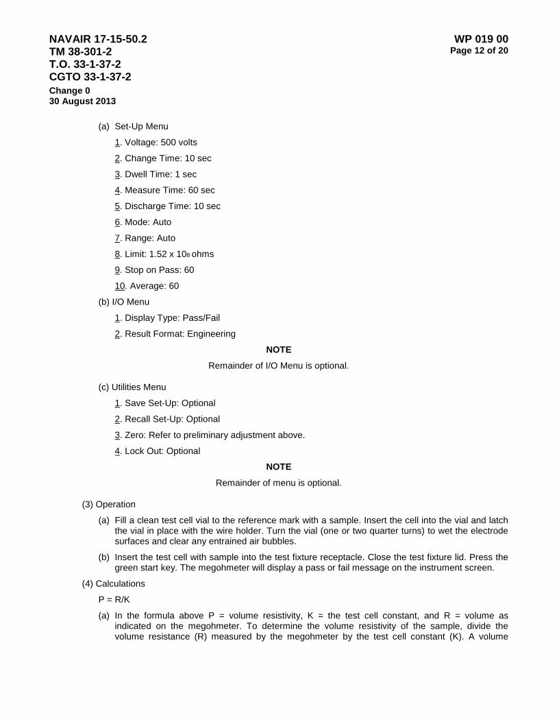
NAVAIR 17-15-50.2 TM 38-301-2 T.O. 33-1-37-2 CGTO 33-1-37-2
WP 019 00 Page 12 of 20
Change 0 30 August 2013
(a) Set-Up Menu
1. Voltage: 500 volts
2. Change Time: 10 sec
3. Dwell Time: 1 sec
4. Measure Time: 60 sec
5. Discharge Time: 10 sec
6. Mode: Auto
7. Range: Auto
8. Limit: 1.52 x 10⁸ ohms
9. Stop on Pass: 60
10. Average: 60
(b) I/O Menu
1. Display Type: Pass/Fail
2. Result Format: Engineering
NOTE
Remainder of I/O Menu is optional.
(c) Utilities Menu
1. Save Set-Up: Optional
2. Recall Set-Up: Optional
3. Zero: Refer to preliminary adjustment above.
4. Lock Out: Optional
NOTE
Remainder of menu is optional.
(3) Operation
(a) Fill a clean test cell vial to the reference mark with a sample. Insert the cell into the vial and latch the vial in place with the wire holder. Turn the vial (one or two quarter turns) to wet the electrode surfaces and clear any entrained air bubbles.
(b) Insert the test cell with sample into the test fixture receptacle. Close the test fixture lid. Press the green start key. The megohmeter will display a pass or fail message on the instrument screen.
(4) Calculations
P = R/K
(a) In the formula above P = volume resistivity, K = the test cell constant, and R = volume as indicated on the megohmeter. To determine the volume resistivity of the sample, divide the volume resistance (R) measured by the megohmeter by the test cell constant (K). A volume
NAVAIR 17-15-50.2 TM 38-301-2 T.O. 33-1-37-2 CGTO 33-1-37-2
WP 019 00 Page 13 of 20
Change 0 30 August 2013
resistivity equal to or greater than 4 x 10¹⁰ ohm per centimeter is acceptable. The cell constant (K) for the JPF-60 test cell is .0038/cm.
(b) In the event the test cell changes, a new limit (volume resistance) will have to be calculated based on the new test cell constant (usually expressed as K) and entered in the megohmeter set-up screen. Using the JPF-60 test cell constant as a reference, calculate the new limit as follows:
P = R/K R = PK = (4 x 10¹⁰) (.0038) = 152,000,000 or
1.52 x 10⁸ ohms
(5) Cleaning cell. For routine cell cleaning, rinse with petroleum ether and wipe with a clean cloth, particularly the area between the tip and the sleeve. Unscrew the outer cylindrical electrode from the cell body. Rinse with petroleum ether and wipe the insulator area with a clean cloth, particularly between the inner electrode and the guard ring.
10. Water Content.
a. Introduction. This procedure describes the method for measuring the water content of silicate ester based coolant with the Karl Fischer Coulometric Titrator (Aquatest 8). The Aquatest 8 uses both the dead stop electrode and the coulometric generation of iodine in a closed vessel system. The coulometric addition of iodine makes the Aquatest an absolute instrument. When a sample is added to the vessel reagent, the voltage rises across the sensing electrode to indicate the wet state. This triggers the coulometer and a constant current flow through the generator producing iodine in the vessel reagent. The iodine reacts with the water from the sample and the vessel solution. When all the water has reacted, the voltage at the sensing electrode drops. This signals the coulometer to stop. The electrical charge produced during the titration is measured coulometrically and is displayed as the total water content. Since the reagent in the vessel is returned to an initial state at the end of each sample addition, sequential analysis can be performed until the vessel reagent is exhausted.
b. Equipment and Materials.
(1) Titrator, Karl Fischer Coulometric (P/N 02-128-10) Solvent
(2) Generator Pyridine Free (50 ml) Solution
(3) Vessel Pyridine Free Isopropyl Alcohol TT-I-735
(4) Methanol O-M-232
(5) Sodium Hydroxide, 1 Normal Solution 0S598
c. Test Information.
(1) The referenced Karl Fischer Coulometric Titrator consists of an Aquatest 8 Titrator and a printer. The Aquatest 8 is a microprocessor-controlled, automated Karl Fischer Coulometric Titrator, which is manufactured by Photovolt, a division of Seradyn, Inc. (FSCM 47125). It is comprised of a base unit, which houses the microprocessor, a titration vessel assembly.
(2) The sample is inserted into the Titractor by means of a sample syringe. The sample will be taken from the sample container and injected into the Titrator's vent hole or its septum opening. At this point, test parameters and other data are input to the Aquatest 8 Titrator via a spill-resistant keypad on the base. The titration is then initiated, via the keypad, and the Aquatest 8 proceeds to automatically perform the titration.

NAVAIR 17-15-50.2 TM 38-301-2 T.O. 33-1-37-2 CGTO 33-1-37-2
WP 019 00 Page 14 of 20
Change 0 30 August 2013
Upon detection of the titration end-point, the results are displayed on the base's sixteen character alphanumeric display. This value can be given in terms of micrograms, percent water, or PPM (parts per million). The printer that is provided with the Aquatest 8 can then be used to obtain hard copies of the test results.
(3) The silicate in the SEBD will react with the reagent to produce water over an extended period of time. The addition of water to the solution will give inaccurate results. In order to remedy the situation, new solution and reagent will be used every 48 hours.
(4) Specifications for the Aquatest 8 are as follows:
(a) Accuracy: 1 microgram or 0.05% whichever is greater.
(b) Capacity: Readouts to 999,999 micrograms of water.
(c) Range: 1 PPM to 100% moisture.
(d) Rate: 2540 micrograms of water per minute.
(e) Electrical: 110 V, 50/60 Hz, 40 Watts
d. Test Procedures.
(1) Instrument Set-Up
(a) Place the Aquatest 8 instrument on the laboratory bench in an area away from direct sunlight and sources of heat such as ovens.
(b) Handle the generator assembly by the Teflon collar.
(c) Holding the vessel cover with the thumbscrews facing away from you, feed the generator plugs and wires through the larger threaded opening. While gently pulling the wires out of the way of the threads, insert the end of the generator that is opened into the cover. Carefully screw the generator into cover.
NOTE
Do not overtighten generator in the vessel cover.
(d) Lightly and evenly grease the ground glass rim of the Pyrex vessel jar with the Photovolt special sealant. Check to see that the three thumbscrew fasteners on the cover are fully unscrewed and extended.
(e) Place a clean and dry magnetic stir bar into the vessel jar.
(f) Carefully join the titration vessel jar and cover with the generator assembly. Twist the cover gently to spread the sealant. Finger tighten the thumbscrew grasps the lip of the vessel jar securely.
(g) Install a membrane septum.
(h) Lightly grease the ground glass collar area of the sensor electrode. Insert the electrode into the small opening of the vessel cover. Carefully and gently seal the collar into the cover. Assure the two circle platinum rings at the end of the electrode are parallel to each other and to the side area of the vessel jar closest to them.
(i) Enter the test parameters into the Aquatest 8 via the keypad.
(2) Pyridine Free Reagent Set-up
NAVAIR 17-15-50.2 TM 38-301-2 T.O. 33-1-37-2 CGTO 33-1-37-2
WP 019 00 Page 15 of 20
Change 0 30 August 2013
(a) In an exhaust hood or well ventilated area, remove the septum holder cap and membrane from the vessel cover, place the funnel supplied into the septum support, and add the entire contents of a bottle of vessel reagent. Remove the funnel and replace the septum and cap.
(b) Remove the generator cap and using a glass syringe, add approximately 3-4 ml of pyridine-free generator solution to the generator. Replace the generator cap.
(c) Place the vessel jar onto the Aquatest 8 inside the plastic retaining ring.
(d) Plug the two banana plugs from the generator into the two banana jacks on back of the Aquatest 8, black-to-black and red-to-red for proper polarity. Plug the sensing electrode plug into the smaller two jacks; the larger sensor plug goes into the small red jack.
(e) Plug the power cable of the Aquatest 8 into a 110-vac grounded receptacle.
NOTE
Assure the Aquatest 8 does not share its power line with devices capable of causing power line disturbances such as motor, compressors, refrigerators and ovens.
(f) Switch on power. The Aquatest 8 will perform internal diagnostics, then display select mode.
NOTE
Once the Aquatest 8 is first turned on, wait 30 minutes before performing a sample assay. This time allow the instrument and vessel assembly to stabilize in its new working environment. Photovolt pyridine-free reagent does not require the use of any neutralizing reagent.
(g) Dipswitch setting should be 1, 2, 4, 8, UP and 3, 5, 6, 7, DOWN.
(h) Turn on the Aquatest 8, and when select mode is displayed press monitor.
(i) Press the first key on the left of the upper 4 keys that correspond to sen.
(j) At this time you will see wet/dry status which will usually show the reagent being at set point or slightly wet; this will be displayed on the Aquatest 8 as follows:
WET….!..^…….DRY.
(k) When the vessel is at set point a caret (^) on the dotted line will appear. The instrument is ready to perform assays.
(3) PPM Moisture Assay.
(a) Press set-up.
(b) Press the fourth white function key under WT.
(c) Press the fourth white function key under NO to enter in a single sample weight.
(d) Press the fourth white function key under NO to allow manual entry of sample weight.
(e) Press clr to remove the weight value stored in memory.
(f) Key the 1800 mg as the weight of the sample and press enter. The Aquatest VIII will beep as it stores the value in memory.
NAVAIR 17-15-50.2 TM 38-301-2 T.O. 33-1-37-2 CGTO 33-1-37-2
WP 019 00 Page 16 of 20
Change 0 30 August 2013
NOTE
In order for the Aquatest 8 microproccessor to compute water content in ppm by weight, it must know the weight of the fluid sample. SEBD has a specific gravity of 0.9, weighing 0.9 grams per ml.
The sample size of 1 ml, therefore, represents a sample weight of 0.9 grams or 900 milligrams (mg). A sample size of 2 ml, therefore, represents a sample weight of 1800 mg.
(g) Again press set-up and this time press the first function key to choose unit.
(h) MCG PCT PPM will be displayed. Press the third function key to choose ppm.
CAUTION
If the test set has not been used for 12 hours or more, initial test results may tend to be inaccurate. Perform two or three analysis, using spare SEBD to allow the test set to stabilize.
NOTE
Since the weight analysis is to be based on the weight transferred, care must be taken to remove all air bubbles from both the syringe and the needle.
Careful wiping of the liquid clinging to the needle is required for precision. Do not draw the tissue all the way over the end of the needle. Wipe to just the edge of the needle tip and then stop. Blot the membrane septum between samples.
(i) Remove the cap from the sample bottle. Using a clean, dry 10 ml glass hypodermic syringe fitted with 4-1/2 inch needle, slowly draw approximately 1 ml of sample fluid from the sample bottle into the syringe. Withdraw the plunger past the 8 ml mark. Coat the interior walls of the syringe with the SEBD. Depress the plunger and expel the 1 ml of SEBD into a waste container. Wipe needle clean.
(j) Using the same 10 ml glass hypodermic syringe fitted with 4-1/2 inch needle, slowly draw approximately 7 ml of sample of fluid from sample bottle into the syringe.
(k) With the needle pointed up, allow the air bubbles to rise to the tip. Place the wiping material halfway over the needlepoint and slowly expel into wiping material any air trapped in the syringe and any fluid in excess of 6 ml. Syringe should now contain exactly 6 ml of sample fluid and no air. Clean the needle with wiping material.
(l) Press set-up. The third option is dly; press the white pad. Next menu will display mcg time. Press the second pad correlating to time. Press the clr key on the keypad and enter 0.3. This is 0.3 minutes or 18 seconds of a delay in the titration. Finally press enter. Now the instrument will delay the start of the titration by 18 seconds after the initial 7-second injection period has elapsed.
(m) Press start. Introduce sample immediately and add sample 7 sec is displayed as follows: Insert needle through membrane septum on sampling port in vessel cover until it is below the level of the vessel solution and discharge precisely 2 ml of fluid directly into the vessel solution. Remove the needle from sampling port. After 7 seconds, the display will show delay for 0.3 minutes and be automatically followed by titration.

NAVAIR 17-15-50.2 TM 38-301-2 T.O. 33-1-37-2 CGTO 33-1-37-2
WP 019 00 Page 17 of 20
Change 0 30 August 2013
(n) At the end of the titration, the weight that is in memory will be displayed as a confirmation test. If it is the correct weight, merely press enter and the results of the assay will be displayed in parts per million water.
NOTE
If the sample weight displayed after titration is incorrect, press clr and enter the correct weight followed by enter. If you are assaying a number of samples of the same weight, you will only need to enter this weight once. Results of water analysis should be reported as an average of at least three runs. Results are considered to have good repeatability if they are within 11 ppm of each other.
(o) Repeat step m above for next injection of the same sample. If a different sample is to be injected, repeat step l above.
(p) Thoroughly clean the syringe, attached needle and plunger with methanol and allow them to air dry. If an explosion-proof oven is available, place the syringe with plunger out of the barrel into the oven at 150-185 degrees F or 65-85 degrees C. After 5 minutes, remove the apparatus from the oven using protection for the hands and insert the plunger into the syringe barrel. Allow it to cool to room temperature (approximately 2 to 3 minutes).
e. Cleaning Generator for Silicate Diester.
(1) The bottom end of the generator assembly consists of a porous Pyrex glass frit. With use, the minute fluid passages in the frit will become clogged, retarding the transfer of generator solution to vessel solution during titration. This condition may be indicated by the error display gen overvoltage and can be corrected by cleaning the frit. (This display does not always occur).
WARNING
Do not get sodium hydroxide (NaOH) solution in eyes, on skin, or on clothing; it causes severe burns. Do not take it internally. Wear gloves and wear goggles (or face shield) when handling. Continuously stir solution while adding compound; add it slowly to surface of solution to avoid violent splattering. Limit the heat rise to 50°F (10°C) per minute. Do not allow temperature of solution to exceed 194°F (90°C) when mixing. Do not use on aluminum parts; reaction with aluminum forms large volumes of hydrogen gas. Flush area of spillage or leakage with water spray.
(2) The generator frit is cleaned by soaking it in a sodium hydroxide (caustic) solution (5, table 6-3) and applying a vacuum to the top of the generator assembly. The vacuum pulls the caustic solution through the frit, opening up the pore structure. To clean frit, proceed as follows:
(a) Remove power from the Aquatest 8 by switching the power off in back of the instrument.
(b) Disconnect the generator and sensing electrode cables from the jacks.
(c) Loosen the three thumbscrews on the vessel cover and swing pawls away from the titration vessel. Use gentle twisting motion to loosen grease seal and remove cover.
(d) Remove generator cap from generator assembly and pour used generator solution into an approved waste container.

NAVAIR 17-15-50.2 TM 38-301-2 T.O. 33-1-37-2 CGTO 33-1-37-2
WP 019 00 Page 18 of 20
Change 0 30 August 2013
(e) Pour used vessel solution into the same waste container used step 4.b.(4). Be careful not to pour out the magnetic stirring bar. Seal the waste container. Next transfer the magnetic stirrer bar from titration vessel onto a clean wiping cloth. Wipe and dry stirring bar.
CAUTION
Do not separate the sensor and generator assembly from the teflon cover.
(f) Grasp Teflon mounting collar on generator assembly and remove from vessel cover by carefully unscrewing threaded section. Remove sensing electrode and wipe it clean.
(g) Using the empty titration vessel, stand sensor and generator assembly to be cleaned in empty vessel. Pour technical grade one Normal (1N) sodium hydroxide (NaOH) solution into the empty vessel jar until a level of approximately 2 inches is reached.
(h) Pour additional solution into top opening of generator assembly, just enough to cover the frit.
(i) Allow generator assembly to soak 4 hours, or longer, in the sodium hydroxide solution. Periodically observe fluid level inside generator. An increase in level will indicate partial clearing of the frit; the open frit allows fluid to transfer from the vessel into the generator. Upon completion of soaking, discard used NaOH solution into an approved waste container, or dispose by approved methods.
(j) Expedite cleaning of porous frit after soaking procedure by the application of a vacuum (not to exceed 15 inches mercury (Hg)) to the generator assembly. Required vacuum can be obtained using the syringe and valve provided with contamination Analysis Kit, part No. 57L414. Locally fabricate required adapters to connect vacuum source to generator, using modified rubber or cork stopper to connect vacuum line to open end of generator.
(k) Place fresh sodium hydroxide solution in emptied titration vessel, enough to partially cover the generator assembly when it is placed in the titration vessel. Apply vacuum to generator assembly until caustic cleaning solution flows freely from the vessel jar to the inside of the generator. Carefully observe fluid level in generator and assure that fluid is not sucked into vacuum line. A filtering flask may be installed as a trap between the generator and the vacuum pump. If required, pour excess fluid from generator assembly to waste
(l) When frit has been cleaned, remove sensor and generator assembly from vessel jar and discard caustic solution into an approved waste container, or dispose by approved methods. Rinse generator assembly and vessel jar using generous amounts of water, preferably hot.
(m) Return generator assembly to the vessel jar and partially fill vessel with water (tap or deionized). Using vacuum procedure specified in steps (j.) and (k.), flush frit with water to remove residual caustic solution.
(n) Remove generator assembly from vessel jar and discard water.
WARNING
Methanol is flammable - Do not use near open flames, near welding area, or on hot surfaces. Do not smoke when using it, and do not use it where others are smoking. Prolonged or repeated inhalation of vapor can cause eye irritation, drowsiness, and headache. Ingestion may be fatal or may cause eye damage. If vapor contacts eyes, immediately flush eyes with large amounts of water. Immediately remove solvent-saturated clothing. If vapor cause drowsiness, remove affected person from area and expose to fresh air. When handling or applying liquid at air-exhausted workbench, wear approved goggles and gloves.
NAVAIR 17-15-50.2 TM 38-301-2 T.O. 33-1-37-2 CGTO 33-1-37-2
WP 019 00 Page 19 of 20
Change 0 30 August 2013
When handling or applying liquid at unexhausted workbench, wear approved respirator, goggles and gloves.
(o) Remove residual water from generator assembly by pulling Methanol through generator with vacuum, as described in steps (j) and (k), and then drying in oven (if available) at 150 to 185°F (65 to 85°C) for a period of 2 hours. If no oven is available, allow to air dry before use. Store generator in desiccator if available, until needed.
(p) In some cases, because of lack of equipment, it may not be possible to clean the frit in shipboard laboratories. In these cases the laboratory should change the generator assembly. The assemblies which need cleaning of the frits should be retained and subsequently taken to a shore based laboratory where cleaning can be accomplished.
f. Calibration.
NOTE
The Aquatest 8 does not require calibration. However, a user calibration procedure is provided so that the user can quickly confirm that the instrument is indeed titrating water accurately. User calibration is generally done every 6 months or as needed (whenever erroneous results are suspected).
(1) Set Aquatest 8 to mcg mode (see paragraph D (g) and (h)).
NOTE
In preparation for the following, fill beaker or other clean container with small amount of tap or deionized water. Set adapter on syringe to 1.0 microliter mark on syringe barrel. Pump syringe several times while needle is submerged in water to remove air. Remove membrane from sample port to enable needle (shorter length) to be below vessel solution.
(2) Press start. Introduce sample immediately after add sample 7 sec is displayed as follows: Insert
needle of a gas tight 2 micro liter syringe (15, table 3-1) with built in Chaney adapter directly through the septum on the sampling port in the vessel cover until it extends below the level of the vessel solution and discharge precisely 1.0 micro liter of water into the vessel solution. After a brief moment, remove syringe and needle from sampling port and replace membrane. After 7 seconds, the display will show delay and be automatically followed by titration. Established that; you obtain 1000 + 50 micrograms of water. Repeat additions until you have 5-10 replicates to determine precision (standard deviation less than or equal to 50 mcg is acceptable). Flush needle several times with water prior to storing to remove chemicals from Aquatest that will cause corrosion.

NAVAIR 17-15-50.2 TM 38-301-2 T.O. 33-1-37-2 CGTO 33-1-37-2
WP 019 00 Page 20 of 20
Change 0 30 August 2013
This Page Intentionally Left Blank

NAVAIR 17-15-50.2 TM 38-301-2 T.O. 33-1-37-2 CGTO 33-1-37-2
WP 020 00 Page 1 of 16
Change 0 30 August 2013
CONTAMINATION TESTING OF COOLANT
Table of Contents
Page
1. Introduction. ....................................................................................................................................................... 1 2. General. ............................................................................................................................................................ 1 3. Equipment. ........................................................................................................................................................ 3 4. Test Sequence. ................................................................................................................................................. 3 5. Laboratory Safety. ............................................................................................................................................ 4 6. Testing. .............................................................................................................................................................. 4 a. Appearance. ................................................................................................................................................ 4 b. Dielectric Strength. ...................................................................................................................................... 5 c. Particulate Contamination. .......................................................................................................................... 7 d. Refractive Index ......................................................................................................................................... 11 e. Specific Gravity. ......................................................................................................................................... 14 f. Accelerated Stability. ................................................................................................................................ 15 g. NaMBT Content. ....................................................................................................................................... 15
1. Introduction. This section defines the procedures, requirements, equipment and material needed for sampling and testing Ethylene Glycol/Water (EGW) used in operating systems such as airborne systems, filtering and fluid supply carts, and other ground servicing equipment. The testing shall provide information on the degradation and contamination of EGW for controlling and monitoring their use.
2. General.
a. The equipment cooling system of the B-2 aircraft incorporates three liquid cooling subsystems and five circulated air subsystems. The liquid cooling subsystems consist of the Ethylene Glycol-Water Subsystem (EGW), DMS/LC Subsystem and the Liquid Cooling Subsystem (LCS).
b. The EGW subsystem is composed of two independent closed cooling loops which use Ethylene Glycol-Water (EGW ) solution as a heat transfer fluid. Each loop circulates coolant from the heat sources and transports the heat to the sink heat exchanger for heat dissipation. The primary heat sources for the EGW loops are the aft bay rack mounted avionics, the forward left avionics, the forward right avionics, the forward left avionics, the forward right avionics, the DMS/LS and the LCS. The Ethylene-Glycol Water subsystem supplies coolant at a flow rate of 85 psig per minute to transport the sink heat from the heat sources to the heat exchangers. The coolant is supplied at a nominal temperature of 47 degrees F with a maximum system pressure of 175 psig.
c. The Ethylene Glycol-Water solution is a mixture of 62.8 + 1.0 percent ethylene glycol by weight, distilled water and appropriate corrosion inhibitors. The EGW coolant appears as a clear, light straw colored liquid and has a characteristic odor. The EGW fluid is composed of the following:

NAVAIR 17-15-50.2 TM 38-301-2 T.O. 33-1-37-2 CGTO 33-1-37-2
WP 020 00 Page 2 of 16
Change 0 30 August 2013
Table 1 - MATERIALS SPECIFICATION
MATERIALS OR SOURCE PART BY WEIGHT
Ethylene Glycol, Technical ASTM E 1119-92 62.80 + 1.00
Triethanolamine- Phosphate (TEAP)
Commercial Grade
1.60 +/- 0.10
50 Percent (by weight) Sodium Mercaptobenzothia-
Zole (NaMBT)
Commercial Grade
0.17 +/- 0.02
Benzotriazole Commercial Grade 0.50 + 0.5 DI Water Commercial Grade 35.00 + 1.00
Table 2 - EGW COOLANT TEST REQUIRMENTS
Appearance Clear and bright, with no evidence of turbidity, haze, cloudiness, gelation, sediment, visible particles or fibers, separation, precipitation, or contamination.
Foaming (Optional) -Increase in volume 5 minutes -350 milliliters, maximum -Break Time -30 seconds, maximum Particulate Contamination per 100 milliliters of Aircraft Fluid, microns:
- 5 to 15 microns - 93,000 particles - 15 to 25 microns - 15,400 particles - 25 to 50 microns - 3,130 particles - 50 to 100 microns - 430 particles - over 100 microns - 41 particles - over 200 microns - 5 particles Particulate Contamination per 100 milliliters of GSE Fluid, microns:
- 5 to 15 microns - 27,000 particles - 15 to 25 microns - 4,000 particles - 25 to 50 microns - 1,300 particles - 50 to 100 microns - 180 particles - over 100 microns - 17 particles - over 200 microns - 2 particles pH at 60ºF 7.80 to 8.50 Refractive Index at 60ºF 1.3900 to 1.4030 Specific Gravity at 60ºF 1.0850 to 1.0910 Accelerated Stability No turbidity, cloudiness, precipitation, deposit
formation, gelation or phase separation after the coolant is heated to 190 F for 24 hours.
Sodium Mercaptobenzothiazole (NaMBT) Content 0.13 to 0.20% by weight 50% NaMBT

NAVAIR 17-15-50.2 TM 38-301-2 T.O. 33-1-37-2 CGTO 33-1-37-2
WP 020 00 Page 3 of 16
Change 0 30 August 2013
3. Equipment/Materials. Equipment identified to each specific test shall be maintained per manufacture's requirements. Records of maintenance and calibration of the equipment shall be maintained. Testing facilities shall be free of contaminates detrimental to test performance and shall be cleaned at intervals deemed necessary to maintain the cleanliness of the area.
Table 3 – EQUIPMENT / MATERIALS Description Manufacturer Part Number NSN
Kim Wipes A-A-1432A 7920-00-721-8884
Paper Towels 7920-00-823-9773
Ethylene Glycol
pH-4
pH-7
Phosphoric Acid
Glacial Acetic Acid
Isopropyl Alcohol Benzotriazole Monobromonaphthalene Goggles (or splash guard) ANSIZ87 1.1989 4240-00-190-6432 Gloves, medium 8415-01-492-0179 Gloves, large 8415-01-492-0178 Gloves, extra large 8415-01-492-0180 Petroleum Ether Methanol pH Meter Corning 245 Particle Counter HIAC 8000A Refractometer Thermometer Water Bath Model F3K 4920-01-096-6405 Hydrometers DI Water
4. Test Sequence. To minimize the quantity of fluid needed to perform the EGW tests and to minimize the effects of sample handling, testing should be conducted in the following sequence:
NAVAIR 17-15-50.2 TM 38-301-2 T.O. 33-1-37-2 CGTO 33-1-37-2
WP 020 00 Page 4 of 16
Change 0 30 August 2013
Paragraph
Appearance 6.a
Dielectric Strength 6.b
Particulate Contamination 6.c
Refractive Index 6.d
Specific Gravity 6.e
Accelerated Stability 6.f
NaMBT Content 6.g
5. Laboratory Safety.
a. Standard lab safety procedures should be followed. All chemicals should be treated as potentially hazardous and handled with care. Petroleum ether and methanol, which will be used to clean the sample containers on the instruments are flammable and should not be exposed to a flame, spark or high heat.. Safety goggles and gloves impervious to organic solvents should be worn at all times. An eye wash station, fire blanket and fire extinguisher should be readily accessible at all times. Material Safety Data Sheets (MSDS) for all chemicals should be accessible to lab personnel while working in the lab. Never work in the lab alone-ensure there is someone else within easy calling distance.
b. Waste chemicals should be disposed of in approved marked waste containers. While the waste organic chemicals used in these procedures may be mixed in a single waste container, it may be more convenient to use one container for EGW waste chemicals and another for EGW wastes. Remove waste chemicals from the lab on a regular basis.
6. Testing.
a. Appearance.
(1). Prior to the sample analysis, the unopened sample bottle shall be visually inspected for proper filling and sealing, as well as evidence of gross contamination. Properly filled bottles will be almost completely filled with fluid extending up to the bottom of the threaded neck section. The purpose of completely filling the bottle is to minimize the quantity of air present, which could contain large amounts of atmospheric moisture, and to assure that adequate fluid is available to perform all of the required tests. Activities submitting EGW fluid samples in improper or inadequately filled bottles shall be advised to resample the equipment.
(2). Prior to sample analysis, fluid in the sample bottle shall be visually inspected for evidence of turbidity or visible particles. This inspection is somewhat limited by translucent plastic bottles but can be remedied by using a clean glass bottle or positioning the plastic bottle in front of a strong light source.
(3). Gross particulate contamination, i.e., particles large enough to be seen with the unaided eye, will also be most visible when the fluid is allowed to stand motionless for a period of time. Particles will generally settle to the bottom of the bottle. Gross particulate contamination is usually indicative of improper sampling technique. If this is suspected, the submitting activity shall be advised and requested to resample the equipment.
NAVAIR 17-15-50.2 TM 38-301-2 T.O. 33-1-37-2 CGTO 33-1-37-2
WP 020 00 Page 5 of 16
Change 0 30 August 2013
(4). Fluid turbidity results in the EGW fluid appearing cloudy as opposed to its normal clear, transparent appearance. Turbidity is most visible when the fluid is agitated and may be indicative of large amounts of air, free water or suspended foreign matter.Turbidity caused by suspended semi-solid matter is of particular concern as it may be indicative of chemical degradation of the EGW fluid. The contamination by-products of such degradation shall be cause for sample rejection.
b. Dielectric Strength.
(1). Introduction. This procedure describes how to measure the pH content of EGW using the type M-245 pH test meter.
(2). Equipment and Materials.
(a) Pyrex Beaker
(b) pH Meter, Corning 245
(c) Glass Electrode
(d) Calomel Electrode, commonly referred to as the reference electrode.
(e) Adapter (if required)
(f) Thermometer - Saybolt Viscosity 14C (Range 19C to 27C, reading to 0.01C)
(g) DI Water
(h) Buffer solution: Buffer solutions can be purchased pre-mixed and certified. (pH 4, pH 7).
(3). Equipment Information and Test Procedures. The referenced pH test meter is an upright box design. On the face of the meter is a keypad operated control panel which programs the calibration, temperature, mode selection, and time interval adjustments.
The pH test meter has the following capabilities:
Range: -2 to 14 pH
Resolution: 0.01 pH
Relative Accuracy: +/- 0.01 pH
Modes: pH
Temperature Span: -5 C to 105 C
Power Requirements: 90 -127 or 198 -264 VAC, 50/60 HZ
NOTE
In use, the pH test meter is first set up with the calomel electrode and pH electrode attached to the electrode holder.
Before beginning the test, standardize instrument with pH and pH7 buffers for maximum accuracy,
Sample should be cooled in a water bath to 60°F or 15.6C before pH testing or calibration begins.
(4). Calibration Procedures.
NAVAIR 17-15-50.2 TM 38-301-2 T.O. 33-1-37-2 CGTO 33-1-37-2
WP 020 00 Page 6 of 16
Change 0 30 August 2013
(a) Calibrate the pH meter, Corning Model 245, as follows:
1. Remove protective caps from electrodes.
2. Remove filler cap from reference electrode.
3. Set the instrument to pH mode.
4. Press cal button.
5. Press right arrow key to select 2 point calibration.
NOTE
Lower display will read "cal 1" and upper display will read "7.00". If the upper display reads "0", press 7.00 on the keypad. Lower display will read "read".
6. Place the electrodes in the pH 7 buffer solution and press the read button. Instrument will automatically adjust to pH 7 and a beep will be heard. Remove electrodes from buffer solution and clean.
7. Lower display will read cal 2 and upper display will read 4.00. If the upper display reads 0 press 4.00 on the keypad. Lower display will read "read".
8. Place electrodes in pH 4 buffer solution and press read button. Instrument will automatically adjust to pH 4 and a beep will be heard. Remove electrodes from the buffer solution and clean. Press exit button. Ensure unit is in pH mode.
9. Verify calibration by measuring pH 4 and pH 7 buffer solutions as if they were a fluid sample.
(5). Test Procedures.
(a) Before beginning the test, measure samples of both pH 4 and pH 7 buffers for maximum accuracy using preceding instructions. If samples do not measure correctly, calibrate instrument..
1. Transfer sufficient volume of EGW fluid into a marked Pyrex beaker to allow the electrode tips to be fully immersed without touching the glass container.
2. Remove electrodes from the storage solution and rinse with DI water. Gently blot the electrodes with clean, soft cloth.
3. Using a twisting motion, remove the plastic caps from the electrodes.
4. Pull black plug out of the electrode fill hole.
5. Measure sample temperature with thermometer.
6. Place pH electrodes in sample. The tips are fully immersed when 1/2 inch into a sample; they may be immersed further, but, never up to the fill holes.
7. Ensure unit is in pH mode.
8. Press read. Instrument will automatically display pH measurement and a beep will be heard.
(6). Care of pH Meter. Remove electrodes from EGW fluid and rinse with DI water. Replace tip protectors and insert black plug into fill hole. The electrodes are stored immersed in pH 7 buffer solution, or distilled water, which is changed after every test setup or weekly at a minimum. Electrodes should be cleaned with DI water and blotted with a clean, soft cloth after each measurement.

NAVAIR 17-15-50.2 TM 38-301-2 T.O. 33-1-37-2 CGTO 33-1-37-2
WP 020 00 Page 7 of 16
Change 0 30 August 2013
CAUTION
Special care should be exercised in handling the electrodes, which are composed of a very fragile glass and may be easily broken.
c. Particulate Contamination.
(1). Introduction. This procedure describes how to perform the counting of particles suspended in EGW using the Hiac/Royco Model 8000A Particle Counter.
(2). Equipment and Materials.
(a) Model 8000A Hiac/Royco Particles Counter with printer
(b) Automatic Bottle Sampler Unit (ABS)
(c) Methanol or Isopropanol (filter the solution through a 0.45 micron filter)
(d) Petroleum Ether (Reagent grade)
(3). Equipment Information.
(a) The referenced particle counting system is comprised of several individual components: A counter, an automatic bottle sampler, and a sensor. Descriptions of each of the components are given below.
1. The counter is equipped with a keypad, a 40 column 16 line liquid crystal display (LCD), and an internal 40 character per line graphics printer. Although wide ranges of contamination standards are resident in the unit, the operator has the option of storing a different standard, which better describes his application. Any of the standards can then be selected with a single keyboard entry. The Model 8000A is capable of acquiring count data for eight particle size ranges. The calibration graph for the sensor being utilized shows the actual values that must be input to the counter to set the size range limits for the test. Whenever a different size range is desired or when a different sensor is utilized, the corresponding calibration graph must be entered into the counter. The calibration graph is supplied by the manufacturer, and the counter is recalibrated every 6 months. Before a test can be run, the operator must input the number of sample runs to be performed. The counter automatically gives results for each sample data run as well as the average of the selected number of runs. The operator must also input the limit for the counter's audible alarm. After the test has been performed, the results can be displayed in either tabular or histogram format, and a hardcopy can be obtained from the printer.
2. The automatic bottle sampler is a Hiac/Royco model ABS sampler (P/N BS-313). The sampler is comprised of three components: A sampler holder, a volume measuring tube, and a control box. The sample to be analyzed is placed in a container inside the sampler holder.
This sample holder has a pressure rating of 60 PSI and is equipped with a magnetic stirrer, which keeps the sample particles in a uniform suspension. Positive pressure is then used to transfer the sample, at a constant flow rate, from the sample holder through the sensor (which will be discussed later) to the volume measuring tube. The pressure required for this transfer can be provided by either a facility air supply or by a separate pump. The sampler is equipped with a locking regulator to regulate the supply pressure down to the desired 5 to 60 psi. Once the sample has passed through the sensor, it goes into the volume measuring tube. This tube is equipped with two moveable light sensors, which generate the "start count" and "stop count" signals to the counter. The volume of sample to be analyzed is determined by the positioning of these two light blocks. Upon completion of a test, the volume measuring

NAVAIR 17-15-50.2 TM 38-301-2 T.O. 33-1-37-2 CGTO 33-1-37-2
WP 020 00 Page 8 of 16
Change 0 30 August 2013
tube is drained by means of an automatic valve and drain line. A Hiac/Royco model HRLD-400 sensor (P/N 040 X 300-01) is provided with the particles in the sample by means of the light obscuration method, has the following specifications:
a. Measurement Range: 2 - 400 microns
b. Recommended Concentration Limit: 8,000 particles/ml
c. Flow Rate: 10 - 200 ml/Min
d. Pressure Limit: 1000 psi
e. Temperature Limit: 150 degrees Fahrenheit
f. Frequency Response: To 250 kHz
g. Precision: Coefficients of variation less than 1% for mean counts greater than 1000 particles per ml
h. Accuracy: Traceable to NIST Standard Reference Materials
(4). Test Procedures.
(a). Turn on the particle counter and the automatic bottle sampler.
(b). Press any key on the keypad to access the main function menu.
(c). Place a container of the sample to be analyzed into the sample holder. Put a clean stirring rod into the container and turn the sample holder's magnetic stirrer on.
NOTE
Be extremely careful that the stir bar is "just" moving to eliminate the counting of bubbles as particles.If a vortex appears in the center of the liquid, it is being stirred rapidly. Adjust stir speed until vortex is no longer visible.
(d). Position the volume measuring tube light blocks. The volume of sample that is analyzed is determined by the positioning of these two blocks. Volume should be set for a 20 ml sample size.
(e). Set the locking regulator on the sample holder to the desired pressure. Desire pressure will provide a flow rate of 20 ml in 20 seconds, ≈ 14 -20 psi.
(f). Press start key.
(g). Once the test is complete obtain results from the display and/or printer.
(h). First flush the system with a total of 100 ml of Methanol or IPA, followed by a flush with 120 ml of Petroleum Ether.
(i). Turn off the particle counter and automatic bottle sampler.
NOTE
If initial set-up data is lost, reenter data using the following calibration procedures.
(5). Calibration Procedures.
(a). Turn unit on and press any key.
(b). Press the more key on the main function menu.

NAVAIR 17-15-50.2 TM 38-301-2 T.O. 33-1-37-2 CGTO 33-1-37-2
WP 020 00 Page 9 of 16
Change 0 30 August 2013
(c). Press the user std key.
(d). Press the alter std key.
(e). Enter the following data:
1. Standard Name: Latex
2. Number of Classes: 16
3. Coml/Diff: Cumulative
4. Class Limit Units: Counts
5. Sample Volume: 20.00 ml
6. Classify: Runs only
7. Number of Runs: 3
8. Number of Channels: 3
9. Class 1 thru 16: N/A
10. Channel 1: 10
11. Channel 2: 200
12. Channel 3: 400
(f) Press exit key.
(g) Save standard in storage slot #1.
(h) Using exit key, return to main menu.
(i) From the main menu, press set-up.
(j) Press the global set-up key and enter the following data:
1. Operator ID: Operator's Initials
2. Number of Runs: 3
3. Delete Time: 00H, 00M, 10S
4. Delay Time: 00H, 00M, 00S
5. Transducer Units: English
6. Quick Adjust Rate: 02H, 30M
(k) Press the exit key to return to the parameter set-up function menu.
(l) Press the control set-up key and enter the following data:
1. Sample ID: 000
2. Background: OFF
3. Dilution Factor: 1.00
4. Standard: Latex in Water
5. Mode: volume

NAVAIR 17-15-50.2 TM 38-301-2 T.O. 33-1-37-2 CGTO 33-1-37-2
WP 020 00 Page 10 of 16
Change 0 30 August 2013
6. Sample Volume: 20.00 ml
(m) Press the exit key and return to the parameter set-up function menu.
(n) Press the exit key to return to the main menu.
(o) From the main menu press the cal key.
(p) Press the set cal key.
(q) Press the alter cal key and enter the following data:
1. Sensor Model: HR-LD400
2. Serial Number: 9306-003
3, Calibration Date: dd/mm/yr
4. Material: Latex in Water
5. Flow Rate: 60 ml/Min
6. Sensor Type: Extinction
7. Algorithm: Interpolation
8. Noise: 13.5 mV
9. Extinction: 12
10. Diameter mV
2.020 41
3.020 60
5.007 132
9.870 309
15.000 475
20.490 641
32.200 1020
40.100 1240
58.500 1720
112.000 3210
165.000 4300
301.000 7500
(r) Press the exit key to go to the calibration function menu.
NAVAIR 17-15-50.2 TM 38-301-2 T.O. 33-1-37-2 CGTO 33-1-37-2
WP 020 00 Page 11 of 16
Change 0 30 August 2013
(s) Press the bin size and enter the following data:
Number of Channels 3
Channel Threshold (micrometers)
1 10 2 200 3 400
(t) Press the exit key to return to the calibration function menu.
(u) Press the exit key and return to the main menu.
NOTE
The tester is now ready for use.
d. Refractive Index
(1). Introduction. This procedure describes the method for measuring the refractive index of EGW coolant fluid using a refractometer and water bath.
(2). Equipment and Materials.
(a) Refractometer
(b) Thermometer - Saybolt Viscosity 17C (range 19C to 27C, reading to 0.01C)
(c) Water Bath, Model F3K
(d) Distilled Water
(e) Glass Standard
(f) Lens Tissue Paper
(g) Methanol
(h) Monobromonaphthalene ***Usually supplied with refractometer for calibration. Calibration procedures are found in the manufacturers manual.
(2). Equipment Information.
(a) The refractometer is a precision optical instrument, with a focusable eyepiece and dispersion corrective prism, equipped for connection to a water bath for uncompensated measurements. It also has an adjustable built-in illumination system.
(b) The refractometer has the following specifications:
1. Display: Direct reading LED
2. Range, Dissolved solids: 0 to 85 degrees Brix, and % solids. Refractive index 1.3210 to 1.7001 ND.
3. Accuracy: +/-0.1 Birx, +/-0.0001 ND, +/-0.1% Solids
4. Temperature Compensation Accuracy: +/- 0.2 degrees Centigrade
5. Sample Types: Transparent or translucent liquids or solids.

NAVAIR 17-15-50.2 TM 38-301-2 T.O. 33-1-37-2 CGTO 33-1-37-2
WP 020 00 Page 12 of 16
Change 0 30 August 2013
6. Sample Temperature Control: Refractive index and uncompensated Brix or % solids.
(c) The circulating heated electric water bath, part number F3-K, NSN 4920-01-096-6405, is used in conjunction with the refractometer. The circulating water bath is necessary to maintain prism temperature so sample is at the desired temperature (60°F).
Calibrate the refract meter with standards such as monobromonaphthalene and a glass standard.
1. The water bath has the following specifications:
2. Mounting type: stand
3. Inside dimensions of the reservoir: 295 x 190 x 150 mm
4. Operating temperature range: 10 to 150 degrees Fahrenheit (-23 to 65 C)
5. Heating element current type: single
6. Heating element wattage in watts: 1000
(d). Test Procedures.
1. Instructions for performing Refractive Index (RI) are as follows:
a Turn on circulating water bath and adjust controls to allow refractometer prism to reach 60°F +/-0.5°F or 15.6°C +/- 0.2°C.
b Place sample container in water bath and allow to come to 60°F +/- 0.5°F or 15.6°C +/- 0.2°C.
c Turn the mode selector to measurement mode N.
NOTE
Prism face is easily scratched which will cause inaccurate measurements. Use only lens tissue designed for instrument cleaning on prism surface.
d Verify prism temperature is 60 degrees F by pressing temp button.
e Open prism assembly and remove lens tissue from prism face (used to protect prism when instrument is not in use). When adding sample be careful not to touch the eyedropper to the prism face. Never "wipe" sample onto prism. Sample should be added dropwise and when prism is closed it will spread.
f Place sample on prism using an eyedropper (the entire surface of the lower prism should be covered). Do not touch prism face with eyedropper.
g Position the illuminator arm and lens for maximum contrast.
NOTE
While viewing through eyepiece, turn the adjustment control knob (located on right hand side of instrument) until the shadow line appears in the reticle field. The adjustment should be counterclockwise when the field appears dark and clockwise when bright.
NAVAIR 17-15-50.2 TM 38-301-2 T.O. 33-1-37-2 CGTO 33-1-37-2
WP 020 00 Page 13 of 16
Change 0 30 August 2013
h Press temperature button on front panel for readout of sample temperature. Sample should be tested at 15.2 - 15.6C.
i When sample reaches correct temperature range, focus on the shadow line. Turn the knob to precisely intersect the shadow line with the cross hair.
j Depress the read button for measurement. Unit will count then display the measurement.
NOTE
If test fails, check accuracy of tester using distilled water. If tester is proven to be accurate, the EGW sample is out of the specification requirement. If test failed, recalibrate the instrument using the calibration procedures.
(e). Calibration Procedures.
1. Calibrate refractometer as follows:
a Turn mode selector to refractive index.
b Open the prism assembly and insure that the surfaces are clean.
c Apply a minute drop of 1-bromonaphthalene to the illuminator end of the refracting prism surface.
d Place the test glass standard on the contact liquid with the polished side down (refractive index alue face up), polished end toward the illuminator end of the refracting prism. Do not use an excessive amount of 1-bromonaphthalene, and avoid build-up along the polished front end of the standard.
e Gently press down on the test glass to insure there are no bubbles between the test glass and the refracting prism.
f Align the illuminator arm and lens so that the front edge face of the test glass is fully illuminated.
NOTE
To achieve the best possible contrast of the liquid field for this measurement, place a sheet of white tissue between the lamp and prism assembly. Diffused lighting will eliminate the black-white fringes (horizontal lines).
g Follow the steps in the general operating instructions for focusing the eyepiece, aligning the shadow line with the cross hair and obtaining a measurement.
NOTE
The alignment of the lamp and color compensation must be accurate. Lamp mis-positioning can create a secondary shadow line. The recognition of the proper contrast line can be easily achieved. Move the illuminator slightly up and down; the primary shadow line will not move. The accuracy of the instrument depends on how well the shadow line is set on the cross half.
h Depress the read button; 1.3330 will be instantaneously displayed, followed by counting. When the counting stops, the ND value of the test glass is displayed. Note the value
NAVAIR 17-15-50.2 TM 38-301-2 T.O. 33-1-37-2 CGTO 33-1-37-2
WP 020 00 Page 14 of 16
Change 0 30 August 2013
shown. The accuracy of calibration should be within 0.0001 ND of the value stamped on the test glass.
i If calibration is necessary, rotate the adjustment control knob and depress the read button, Repeat until the correct value, as indicated on the test glass, is obtained. Insert the allen wrench provided through the access hole in the dispersion control. Turn the adjusting screw carefully to move the reticle up and down until the shadow line is aligned with the center of the crosshair. Remove the test glass; clean and close the prism assembly.
CAUTION
Care should be taken to avoid any contact between the edges or sharp corners of the solid sample and the prism. If the flat surface of the sample is smaller than the refracting prism, place the sample on the far half of the prism surface, toward the illuminator. This will improve the contrast line visibility.
(f). Care of Refractometer. - Prism should be cleaned after each sample is removed with a soft cloth or cotton swab dampened with DI water. The prism may be wiped with lens cleaning tissues but it should NOT be wiped with a hard, dry cloth.
e. Specific Gravity.
(1). Introduction. This procedure describes the method of measuring the specific gravity of EGW using the hydrometer.
(2). Equipment and Materials.
(a) Glass Stirrer or Glass Rod (to use with cylinder)
(b) Thermometer - Gravity 12 C, (range -20 to +120 C) or 12 F (range -5 to +215 F)
(c) Water Bath
(d) Hydrometers, Numbers 111H to 117H, specific gravity range 1.000 to 1.350, precision 0.050 each hydrometer.
(e) Hydrometer Cylinder
(3). Test Procedures.
NOTE
Assure that the sample temperature is 60 ºF + 0.5 F, by immersing a thermometer into sample.
(a) Carefully pour the sample into the hydrometer cylinder without splashing. Remove the bubbles formed after they have collected on the surface of the sample by touching with a clean, dry glass rod. Fill cylinder about 2/3 - 3/4 full.
(b) Place sample in water bath and allow sample to reach 15ºC (60ºF).
(c) Lower the hydrometer gently into the sample. Avoid wetting the stem above the level to which it will be immersed. Stir the sample with glass rod, and record the temperature when a steady temperature has been reached. Remove the thermometer after recording temperature.
NAVAIR 17-15-50.2 TM 38-301-2 T.O. 33-1-37-2 CGTO 33-1-37-2
WP 020 00 Page 15 of 16
Change 0 30 August 2013
(c) Depress the hydrometer about two scale divisions into the sample and then release it, imparting a slight spin.
(e) When the hydrometer has come to rest away from the cylinder walls and with no air bubbles present, read the density/specific gravity, by placing the eye slightly below the level of the liquid and slowly raising it until the surface of the sample becomes a straight line cutting the hydrometer scale.
(f) Again determine the sample temperature. If this differs from the initial value, repeat the hydrometer test and then thermometer observations until no more than 1 ºF difference is obtained.
(g) Report the specific gravity/relative density to the nearest 0.001, and temperature measurement to the nearest 1ºF.
f. Accelerated Stability.
(1). Fill a 100-ml centrifuge tube to the 100 +0, –2 ml mark with coolant or add coolant to an acceptable level in a 100 ml to 500 ml three-neck flask so that a thermometer will have its bulb in the fluid. Cap with a properly sized one-hole rubber or cork stopper.
NOTE
Cork stopper particles will float. Rubber particles will not.
(2). Insert a 12-inch long glass condenser tube through the stopper. Insert a dry Nichrome or stainless wire into the condenser past the bottom of the condenser but not into the coolant as shown in ASTM D5828 Figure 1. The purpose of the wire is to provide a means of directing condensate back to the centrifuge tube. It is also permissible to have the fluid in a 100 ml to 500 ml three-neck flask and to utilize a 600 mm Vigreux distillation column in the center neck with an appropriate thermometer in one of the side necks and a solid rubber, cork, ground glass or Teflon stopper in the other side neck.
(3). Expose the fluid to a target temperature of 200 F for 24 to 30 hours. It is permissible for the fluid temperature to fluctuate between 185 F and 210 F during the test. At the end of the test period, remove the fluid from the heat source and allow to cool to room temperature for at least one hour.
(4). Remove the air condenser and stopper and replace with a solid rubber or cork stopper. Balance the centrifuge tube, stopper and fluid sample against another centrifuge tube (with stopper) containing another coolant sample that was not heated 190 F. If a three-neck flask was used, decant 100 ml +0, –2 ml of cooled fluid into a 100 ml centrifuge tube, then balance with another centrifuge tube filled with coolant to 100 ml +0, –2 ml.
g. NaMBT Content.
(1). Adjust reagent grade deionized water (resistivity > 3,000,000 ohm-cm) to a pH of 5.2 using a pH meter, a small Pasteur pipette and glacial acetic acid that is diluted to 1% acetic acid by volume. Stir the water constantly with a magnetic stirrer while adding the diluted acetic acid. Use a Ross combination electrode or other suitable sensing electrode. Adjust at least 500 ml of deionized water that has been freshly boiled and allowed to cool to room temperature while covered.
NOTE
UV-visible measurement of NaMBT in EGW is not feasible because the 310-nm peak for this compound is strongly interfered by other ingredients that absorb at a lower but close frequency. If NaMBT is converted to MBT by adjusting the pH to near 5.2, the analytical peak changes to 322nm where the interference is slight.

NAVAIR 17-15-50.2 TM 38-301-2 T.O. 33-1-37-2 CGTO 33-1-37-2
WP 020 00 Page 16 of 16
Change 0 30 August 2013
(2). Adjust a 100 ml sample of the coolant to a pH of 5.2 using reagent grade or better glacial acetic acid, a small Pasteur pipette, a magnetic stirrer, and a pH meter with Ross or other suitable electrode. Stir the sample constantly while adding the acid drop wise.
(3). If available, use reagent grade ethylene glycol, benzotriazole, deionized water, triethanolamine, and phosphoric acid to formulate EGW fluid in accordance with MS-139, omitting the 50% NaMBT. Standards cannot be made using water alone, since the NaMBT is converted to the MBT form at pH 5.2, and is insoluble in water. Adjust the pH of the fluid to 5.2 as per step 2, then add known amounts of 50% NaMBT (R.T. Vanderbilt “NACAP”) to the fluid (weighing to the nearest 0.1 mg) to provide the desired standard (suggested approximate values of weight % of 50% NaMBT added to the fluid are 0.05, 0.10, 0.15, 0.20, and 0.25). Store the standards in a dark place in carefully sealed bottles (amber glass preferred).
(4). Use pH 5.2 water or pH 5.2 EGW with no NaMBT to fill both cells and perform a baseline analysis. Perform a zero analysis as well, operating the instrument in accordance with the manufacturer’s instructions. After completion of the baseline analysis, remove the cell from the sample beam, and leave the cell in the reference beam.
(5). Dilute a 1 ml aliquot of each standard with pH 5.2 water to 1% standard by volume for a 1 cm cell or 10% standard by volume for a 1 mm cell. Use a Class A glass pipette or a Gilmont Micrometer Buret to obtain the 1 ml sample for the Cary 400 spectrophotometer. Other spectrophotometers may require different dilutions. Rinse the cell down with the diluted sample, then fill, and place in the sample beam. Scan the sample from 500 nm to 200 nm or other desired wavelengths, as long as there is sufficient distance on either side of the 322 nm peak. Multiple scans may be performed if the instrument does not demonstrate sufficient repeatability (the Cary 400 typically will not vary more than 0.001 absorbance unit from run to run, and does not normally required more than one analysis). Print the results, making note of the absorbance at 322 nm, and determine the absorbance of the valley just to the left of the 322 nm peak, and of the baseline to the right. Add the two absorbances on either side of the 322 nm peak, divide by two, and subtract from the 322 nm absorbance. Repeat for all of the standards, so as to have a reference range for all analyses. Use only Class A glass volumetric flasks for all dilutions.
(6). Use a Class A glass pipette or a Gilmont micrometer buret to obtain a 1 ml aliquot of the sample, and dilute as specified in step 5. Perform the analysis per step 5, and determine the 50% NaMBT content by computing the ratio of the net absorbance of the sample (calculated as in step 5) to the standard closest in net absorbance to the sample, and multiplying by the amount of NaMBT in the standard. Alternatively, the absorption coefficient may be determined using Beer’s law (A = axbxc; b= pathlength of the cell, c is the concentration in whatever desired units, and a is the absorption coefficient) and at least two of the known concentration standards. The method of known additions may be used when NACAP and only used MS-139 are available. Add a known amount of NACAP to the EGW fluid after analysis, dilute as in step 5, and analyze.Use the 2 net absorbances to determine your absorption coefficient via subtraction and division into the remaining net absorption. The weight % of 50% NaMBT = net absorbance divided by response factor.
NOTES
Do not calculate concentration based on just the maximum peak values of the samples and the standard or use nonscanning UV-visible spectrometers that measure fixed wavelengths. Do not determine concentration based on the area of the 322 nm peak rather than the peak height. Samples with lower concentrations of NaMBT give slightly higher values when analyzed by UV-visible spectroscopy because the interference is relatively greater for these samples.

NAVAIR 17-15-50.2 TM 38-301-2 T.O. 33-1-37-2 CGTO 33-1-37-2
WP 021 00 Page 1 of 6
Change 0 30 August 2013
FLUID CONTAMINATION
Table of Contents
Page
1. Introduction ........................................................................................................................................................ 2 2. Types of contamination ...................................................................................................................................... 2 a. Environmental ............................................................................................................................................... 2 b. Wrong fluid type. ........................................................................................................................................... 2 c. Wear debris. .................................................................................................................................................. 2 d. Operational byproducts. ................................................................................................................................ 2 3. Identifying and measuring contamination. ......................................................................................................... 2 a. Water............................................................................................................................................................. 2 b. Particulate debris. ......................................................................................................................................... 3 c. Wrong fluid type. ........................................................................................................................................... 3 (1). Zinc. ........................................................................................................................................................ 3 (2). Molybdenum. .......................................................................................................................................... 3 (3). Boron. ..................................................................................................................................................... 3 (4). Magnesium ............................................................................................................................................. 3 (5). Glycol. ..................................................................................................................................................... 3 (6). Analytical techniques. ............................................................................................................................ 4 d. Operational byproducts. ................................................................................................................................ 4 e. Wear debris. .................................................................................................................................................. 4 4. Consequences of contamination ........................................................................................................................ 4 a. Water............................................................................................................................................................. 4 b. Environmental particulate debris and soot. .................................................................................................. 4 c. Wrong fluid type. ........................................................................................................................................... 4 d. Operational byproducts. ................................................................................................................................ 4 e. Fuel .............................................................................................................................................................. 4 f. Wear debris. .................................................................................................................................................. 5 5. Mandatory actions for addressing contamination .............................................................................................. 5 a. Environmental debris and water. .................................................................................................................. 5 b. Visible particulate debris. .............................................................................................................................. 5 c. Wrong fluid type. ........................................................................................................................................... 5 d. Operational byproducts. ................................................................................................................................ 5 e. Wear debris. .................................................................................................................................................. 5
NAVAIR 17-15-50.2 TM 38-301-2 T.O. 33-1-37-2 CGTO 33-1-37-2
WP 021 00 Page 2 of 6
Change 0 30 August 2013
1. Introduction - This section discusses the contamination of lubricating and hydraulic fluids, how it occurs, how it is identified, what its impacts are, and what to do when contamination is suspected.
2. Types of contamination - Essentially, anything that is not supposed to be in the oil sump is a contaminant, regardless of its source. Contaminants may enter the system as a result of environmental exposure, normal operation, normal or abnormal wear, or human error (wrong fluid type).
a. Environmental. Environmental contamination occurs when materials normally present in the environment enter the oil. Environmental contamination can occur when fluid is transferred or when any reservoir (cart, pre-oiler, can, drum) is open to the environment. Environmental contaminants include (1) finely divided, airborne and windborne soil, dust, sand, or clay, (2) large particles of debris from contaminated surfaces, such as corroded cans, and (3) water from rain, snow, or other sources. Environmental contamination is largely a function of the environmental conditions under which fluids are stored and transferred and the care taken by personnel to ensure cleanliness and to protect transfer. Environmental contamination occurs when (1) bottles, cans, pre-oilers, or oil carts are left open or in unprotected conditions for extended periods, (2) closures malfunction or seals/gaskets have degraded, (3) drum or can surfaces are allowed to corrode and debris enters the oil as the container is opened, (4) dirty can openers, church keys, pour spouts, funnels, or nozzles are used, or (5) contaminants enter through the component air intake (or other exposure) as a result of normal operation. Improvements in personnel training and material handling equipment have reduced much of the environmental contamination.
b. Wrong fluid type. This results from human error (such as putting the wrong fluid in a pre-oiler) or sloppy handling (such as reusing a pre-oiler for a different type of fluid without proper cleaning). Contamination with the wrong fluid type most commonly occurs when an oil cart or pre-oiler (for example, PON-6) is filled with the wrong material at the maintenance site. However, it is also possible for mix-ups to happen in the supply system. Any time fluid is transferred between containers or to a vehicle’s oil sump, there is an opportunity for contamination. There are three general types of fluids used in aircraft: hydraulic fluids (MIL-PRF-83282 and MIL-PRF-5606), mineral lubricants [SAE J1899 (formerly MIL-L-22851D) and SAE J1966 (formerly MIL-L-6802E)], and synthetic lubricants (MIL-PRF-7808 and MIL-PRF-23699). However, there are many types of vehicles and components (engines, transmissions, gearboxes) enrolled in the JOAP. There are also many types of fluids used in servicing mechanical equipment (antifreezes or coolants, fuels, additives, lubricants, and hydraulic fluids). Any of these types of fluid may be inadvertently added to the oil sump or to an intermediate container (i.e., between the manufacturer’s container and the sump.
c. Wear debris. Friction from moving parts and abrasion from environmental debris causes small fragments of metal to slough off into the oil. Excessive wear debris indicates poor engine health. For aeronautical equipment, nearly the entire oil analysis program is directed towards wear debris and engine health.
d. Operational byproducts. Chemical reactions that take place during combustion yield products that reduce oil quality and effectiveness. Soot is formed from the incomplete combustion of hydrocarbon fuels. Water formed by combustion and fuel vaporized during combustion may enter the oil. Sulfur and phosphorus compounds may occur as impurities in diesel fuel and will burn to produce acids that attack metallic parts. Heat and mechanical stress break down the long hydrocarbon chains of the compounds that make up the oil itself.
3. Identifying and measuring contamination. Much of the JOAP Manual is dedicated to detecting and quantitating wear debris contamination and/or operational byproduct contamination.
a. Water. Although water is an environmental contaminant, it is also an operational byproduct that forms as
NAVAIR 17-15-50.2 TM 38-301-2 T.O. 33-1-37-2 CGTO 33-1-37-2
WP 021 00 Page 3 of 6
Change 0 30 August 2013
a result of combustion of hydrocarbon fuels; therefore, it is already addressed when it represents a significant threat to a component or to oil performance. Water is measured via the crackle test, Karl Fischer titrimetry, and infrared spectrometry. These topics are covered in Volume II Section V of the JOAP Manual and are a part of routine analysis for many samples.
b. Particulate debris. This includes environmental particulate debris and soot. Dust, sand, grit, clay, and soil can be encountered as environmental particulate debris. Silicon is present in sand (silicon dioxide). When silicon is found with aluminum, that suggests the presence of aluminosilicates found in soils and clays. High levels of iron, inconsistent with engine composition, may be from rust on a can, can opener, pour spout, or church key. Many aircraft engine oils contain low concentrations of silicon in the form of silicone pour point depressants that allow the oil to be dispensed easily in cold weather. Therefore, it is normal to see silicon concentrations around 3-4 ppm and occasionally as high as 5-6 ppm. Silicon, aluminum, and iron are all quantitated via rotrode atomic emission spectroscopy, which is covered heavily in Volume II WP 001 00, and to which the wear limit tables in Volumes III and IV are dedicated. In addition, particle counting is used for hydraulic fluids and covered in Volume II Section V.
c. Wrong fluid type. Wrong fluid type is normally found by identifying additives that would be absent in the correct fluid.
(1). Zinc. High levels of zinc are consistent with MIL-PRF-2104 or other automotive lubricants. As of 2005, zinc dialkyldithiophosphate (ZDDP) compounds are still added as antiwear agents to engine oils. These compounds form protective zinc phosphate glasses on engine parts. ZDDP compounds are not used in turbojet oils.
(2). Molybdenum. Although not routinely found in MIL-PRF-2104, many commercial automotive (e.g., 5W30, 10W40) and truck (e.g., 15W40, 20W50) oil formulations incorporate suspensions of molybdenum disulfide. Molybdenum disulfide is a solid lubricant, and it is found in both engine oils and anti-seizing compounds. Unfortunately, molybdenum is also used in many aircraft engine bearings (such as 4.0-4.5% in M50 steel). The presence of molybdenum alone is not diagnostic for wrong fluid type. When detected in the oil of a component that does not contain molybdenum, this finding does point to contamination with automotive/truck engine oil.
(3). Boron. Historically, the presence of boron has suggested the presence of coolant in the oil since borates are used as buffers to control pH in cooling systems. Nevertheless, boron additives, such as boron nitride, are found as solid lubricants, especially in heavy weight (e.g., 20W50) commercial oils. As of 2005, boron compounds were not used in any qualified product under MIL-PRF-2104 in the Defense supply system, and the presence of boron should initially suggest contamination with antifreeze coolant.
(4). Magnesium. Historically, the presence of magnesium has suggested the presence of coolant in the oil since magnesium compounds are used as detergents in cooling systems. However, it has become increasingly common for the same detergents to be used in automotive/truck engine oils. When detected in the oil of a component that does not contain magnesium, this finding points to contamination with either automotive/truck engine oil or antifreeze coolant.
(5). Glycol. Most antifreeze coolant formulas are based on ethylene glycol, but environmentally friendly formulations contain propylene glycol. The alcohol functional groups are observed by infrared spectroscopy. Contamination with antifreeze coolant occurs mostly in ground equipment and rarely in aircraft. Glycol contamination usually occurs simultaneously with water contamination.
NAVAIR 17-15-50.2 TM 38-301-2 T.O. 33-1-37-2 CGTO 33-1-37-2
WP 021 00 Page 4 of 6
Change 0 30 August 2013
(6). Analytical techniques. Zinc, molybdenum, and boron are determined via rotrode atomic emission spectrometry. Glycol and some other additives can be determined by infrared spectrometry. Some services and some laboratories may not have all techniques available.
d. Operational byproducts. In addition to water, various acidic species may be formed by the partial combustion of hydrocarbon fuels or impurities in them; these are measured collectively as the total acid number. Though not a byproduct, vaporized fuel may enter the oil during operation, and so it is included here. Fuel contamination can be determined by decrease in the flash point or fuel sniffer (Volume II Section V) as well as a decrease in viscosity when severe. Decreases in viscosity are also associated with the degradation of the oil itself resulting from exposure to heat and mechanical shearing action.
e. Wear debris. Like environmental particulate debris, wear debris is determined primarily by rotrode atomic emission spectrometry. Most wear debris is too large to remain suspended in the oil so that it cannot be estimated by the oil’s opaqueness to infrared light (unlike soot). Volume II Section III is devoted to rotrode atomic emission spectrometry.
4. Consequences of contamination
a. Water. Small amounts of water are dispersed by the surfactants in the oil; however, large amounts of water lead to the formation of sludge, which clogs the filter and increases the viscosity. As sludge forms, the oil becomes less effective at lubricating surfaces and less effective at conducting heat energy. This makes the engine work harder and wear out faster. Water also speeds corrosion.
b. Environmental particulate debris and soot. Depending on the particle size, these contaminants either interfere with the proper function of the dispersants and surfactants in the oil (leading to sludge formation) or they abrade the moving parts of the engine. In most aircraft, large debris is removed by the oil filter so that the presence of individually visible particles (i.e., turnings, chunks, flakes, needles) suggests improper filter function. Even in ground equipment, individually visible particles suggest substantial engine wear and/or poor air/oil filtration.
c. Wrong fluid type. For aircraft, wrong fluid type can be an extremely serious problem. Aircraft consume oil at a rate such that any noncombustible or involatile compounds are rapidly concentrated and can clog filters or deprive the system of needed lubrication and heat transference. Furthermore, aircraft components are not designed for exposure to some of the additives present in automotive/truck engine oils. Because aircraft lubricants are relatively free of additives, it is difficult to identify contamination of automotive/truck oil with aircraft oil, but it is also less serious.
d. Operational byproducts. Acidic compounds produced from the burning of sulfur or phosphorus impurities in fuel, incomplete combustion of hydrocarbon fuels, or nitrogen oxides formed from air at operating temperatures all attack metallic engine parts, corroding them. They also react with seals and gaskets, reducing their lifetimes.
e. Fuel. Excessive levels of fuel (about 5% by weight or higher) pose a safety risk by making the oil combustible or even flammable. Fuel incursion lowers viscosity, which, in turn, reduces lubricity. It also decreases thermal conductivity. Fuel incursion is primarily a concern for ground equipment and diesel engines.
NAVAIR 17-15-50.2 TM 38-301-2 T.O. 33-1-37-2 CGTO 33-1-37-2
WP 021 00 Page 5 of 6
Change 0 30 August 2013
f. Wear debris. Depending on the level of debris and the component, the debris may be normal or abnormal. In precision gas turbine engines, even small amounts of wear debris can signal an impending engine failure. The wear debris limits for aeronautical equipment are given in JOAP Manual Volume III. The wear debris limits for ground equipment are given in JOAP Manual Volume IV. Safety of flight dictates that special attention is given to aircraft. As a rule, limits for aircraft are much lower than limits for ground equipment or diesel engines on ships. Wear debris results should ideally be diagnostic (identifying what part is failing) and prognostic (how long that part will last). When coupled with knowledge of the engine composition and design, wear debris analysis is an important aspect to a condition-based maintenance program.
5. Mandatory actions for addressing contamination
a. Environmental debris and water. Recommend resampling and retesting when dust, dirt, sand, soil, clay, or water is suspected. Confirm proper instrument function with appropriate check standards. Recommend continual flushing, sampling, and testing until contamination is undetectable (< 8.0 ppm Si if no limit given) or nearly so. Consult program manager if further information is needed. Compare results with reported limits in JOAP Manual Volumes III and IV limit tables.
b. Visible particulate debris. When visible debris is present, regardless of the nature of the debris (wear or environmental), the sample fails automatically. Confer with mechanic or maintenance chief if appropriate to ensure sample was not contaminated during/after collection. Recommend resampling or draining/flushing if evidence indicates. Test to identify and quantitate wear debris in original sample and any additional samples.
c. Wrong fluid type. Report results suggesting wrong fluid type as soon as practical; recommend resampling and retesting. Confirm proper instrument function with appropriate check standards. When wrong fluid type has been verified, notify local chain of command, oil analysis program manager, maintenance chief, cognizant engineering authority (Army and Navy only), and other personnel as required by local written procedures. When contamination has been identified in sealed materials procured through the Defense supply system, initiate action through the Defense supply deficiency reporting system. Recommend continual flushing, sampling, and testing until contamination is undetectable (< 8.0 ppm Zn and B) or nearly so. Consult program manager if further information is needed.
d. Operational byproducts. Report results as required for individual components or equipment. Report recommendations for additional sampling and testing or maintenance as required. Further detail is provided elsewhere in the manual.
e. Wear debris. When metallic debris consistent with component wear is confirmed by rotrode atomic emission spectrometry (RAES), take action consistent with the wear limit tables in JOAP Manual Volumes III and IV.

NAVAIR 17-15-50.2 TM 38-301-2 T.O. 33-1-37-2 CGTO 33-1-37-2
WP 021 00 Page 6 of 6
Change 0 30 August 2013
This Page Intentionally Left Blank
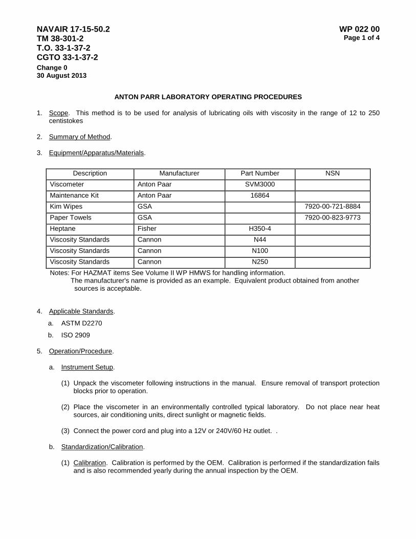
NAVAIR 17-15-50.2 TM 38-301-2 T.O. 33-1-37-2 CGTO 33-1-37-2
WP 022 00 Page 1 of 4
Change 0 30 August 2013
ANTON PARR LABORATORY OPERATING PROCEDURES
1. Scope. This method is to be used for analysis of lubricating oils with viscosity in the range of 12 to 250 centistokes
2. Summary of Method.
3. Equipment/Apparatus/Materials.
Description Manufacturer Part Number NSN
Viscometer Anton Paar SVM3000 Maintenance Kit Anton Paar 16864 Kim Wipes GSA 7920-00-721-8884 Paper Towels GSA 7920-00-823-9773 Heptane Fisher H350-4 Viscosity Standards Cannon N44 Viscosity Standards Cannon N100 Viscosity Standards Cannon N250 Notes: For HAZMAT items See Volume II WP HMWS for handling information. The manufacturer's name is provided as an example. Equivalent product obtained from another
sources is acceptable.
4. Applicable Standards.
a. ASTM D2270
b. ISO 2909
5. Operation/Procedure.
a. Instrument Setup.
(1) Unpack the viscometer following instructions in the manual. Ensure removal of transport protection blocks prior to operation.
(2) Place the viscometer in an environmentally controlled typical laboratory. Do not place near heat sources, air conditioning units, direct sunlight or magnetic fields.
(3) Connect the power cord and plug into a 12V or 240V/60 Hz outlet. .
b. Standardization/Calibration.
(1) Calibration. Calibration is performed by the OEM. Calibration is performed if the standardization fails and is also recommended yearly during the annual inspection by the OEM.
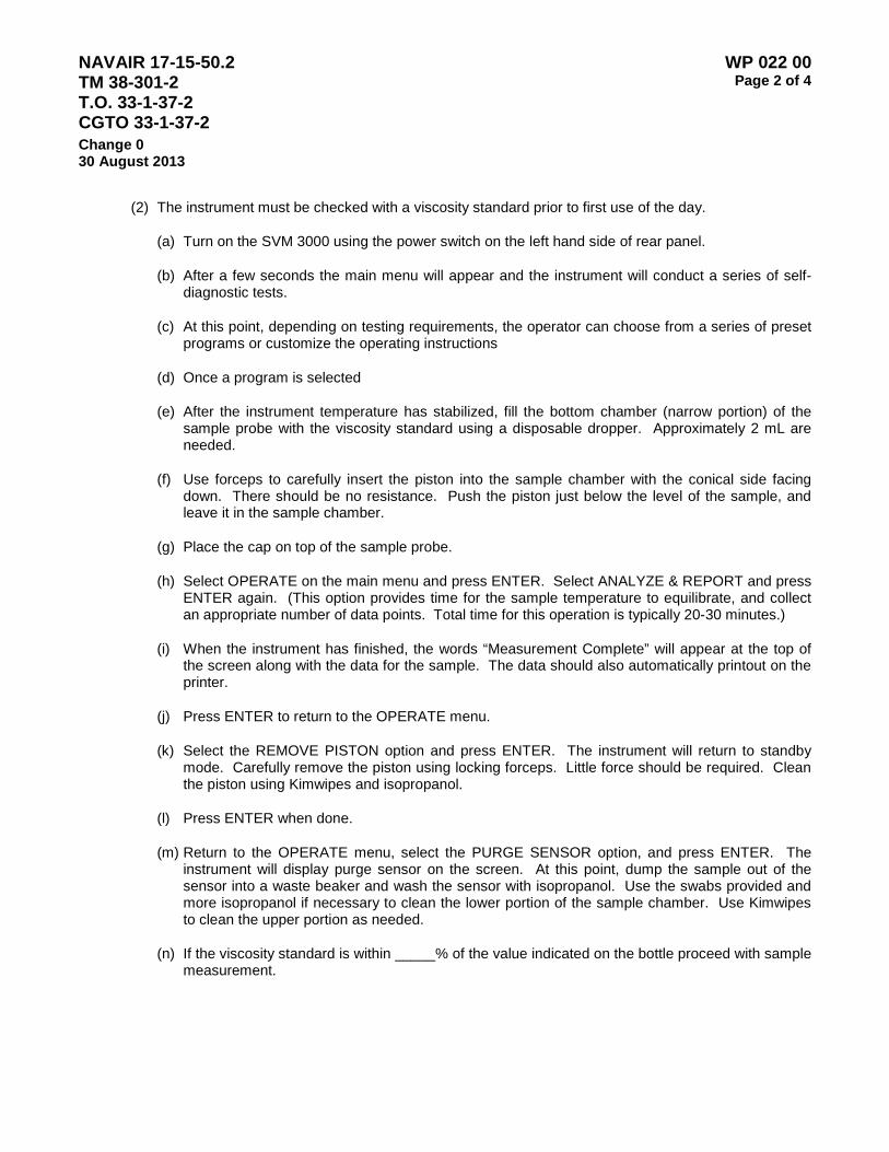
NAVAIR 17-15-50.2 TM 38-301-2 T.O. 33-1-37-2 CGTO 33-1-37-2
WP 022 00 Page 2 of 4
Change 0 30 August 2013
(2) The instrument must be checked with a viscosity standard prior to first use of the day.
(a) Turn on the SVM 3000 using the power switch on the left hand side of rear panel.
(b) After a few seconds the main menu will appear and the instrument will conduct a series of self-diagnostic tests.
(c) At this point, depending on testing requirements, the operator can choose from a series of preset programs or customize the operating instructions
(d) Once a program is selected
(e) After the instrument temperature has stabilized, fill the bottom chamber (narrow portion) of the sample probe with the viscosity standard using a disposable dropper. Approximately 2 mL are needed.
(f) Use forceps to carefully insert the piston into the sample chamber with the conical side facing down. There should be no resistance. Push the piston just below the level of the sample, and leave it in the sample chamber.
(g) Place the cap on top of the sample probe.
(h) Select OPERATE on the main menu and press ENTER. Select ANALYZE & REPORT and press ENTER again. (This option provides time for the sample temperature to equilibrate, and collect an appropriate number of data points. Total time for this operation is typically 20-30 minutes.)
(i) When the instrument has finished, the words “Measurement Complete” will appear at the top of the screen along with the data for the sample. The data should also automatically printout on the printer.
(j) Press ENTER to return to the OPERATE menu.
(k) Select the REMOVE PISTON option and press ENTER. The instrument will return to standby mode. Carefully remove the piston using locking forceps. Little force should be required. Clean the piston using Kimwipes and isopropanol.
(l) Press ENTER when done.
(m) Return to the OPERATE menu, select the PURGE SENSOR option, and press ENTER. The instrument will display purge sensor on the screen. At this point, dump the sample out of the sensor into a waste beaker and wash the sensor with isopropanol. Use the swabs provided and more isopropanol if necessary to clean the lower portion of the sample chamber. Use Kimwipes to clean the upper portion as needed.
(n) If the viscosity standard is within _____% of the value indicated on the bottle proceed with sample measurement.

NAVAIR 17-15-50.2 TM 38-301-2 T.O. 33-1-37-2 CGTO 33-1-37-2
WP 022 00 Page 3 of 4
Change 0 30 August 2013
(3) Processing Samples.
(a) Press the down arrow until the choice for “Units of Measure” can be selected. Select the Units of measure and set the viscosity units to Centistokes. The instrument will prompt for a density entry. Use table __________ and enter the density of the fluid being tested.
TABLE____ Fluid Densities
(b) Select the TEMPERATURE CONTROL option by using the arrow keys to move the “select arrow” to the option. Press the ENTER button to open the TEMPERATURE CONTROL menu.
(c) Select HEATER ON and set the temperature to 40 degrees C. If the temperature set point is correct press ENTER twice. (If a change in temperature is needed use the ESCAPE and ENTER buttons and left and right buttons respectively. The arrow buttons will change the numerals.)
(d) Once a temperature is selected and the heater is on, the instrument will display “Sensor is standby.” At this point allow the instrument temperature time to reach the set point and stabilize until the uncertainty in the temperature reading is less than or equal to +/- 0.1 °C. (For example, before moving on to the next step a 40 °C set point should have a reading of 40.0 °C +/- 0.1 °.)
(e) After the instrument temperature has stabilized, fill the bottom chamber (narrow portion) of the sample probe with the viscosity standard using a disposable dropper. Approximately 2 mL are needed.
CAUTION
Ensure that the sample is free from particulate matter and bubbles.
(f) Use forceps to carefully insert the piston into the sample chamber with the conical side facing down. There should be no resistance. Push the piston just below the level of the sample, and leave it in the sample chamber.
(g) Place the cap on top of the sample probe.
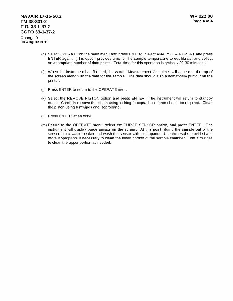
NAVAIR 17-15-50.2 TM 38-301-2 T.O. 33-1-37-2 CGTO 33-1-37-2
WP 022 00 Page 4 of 4
Change 0 30 August 2013
(h) Select OPERATE on the main menu and press ENTER. Select ANALYZE & REPORT and press ENTER again. (This option provides time for the sample temperature to equilibrate, and collect an appropriate number of data points. Total time for this operation is typically 20-30 minutes.)
(i) When the instrument has finished, the words “Measurement Complete” will appear at the top of the screen along with the data for the sample. The data should also automatically printout on the printer.
(j) Press ENTER to return to the OPERATE menu.
(k) Select the REMOVE PISTON option and press ENTER. The instrument will return to standby mode. Carefully remove the piston using locking forceps. Little force should be required. Clean the piston using Kimwipes and isopropanol.
(l) Press ENTER when done.
(m) Return to the OPERATE menu, select the PURGE SENSOR option, and press ENTER. The instrument will display purge sensor on the screen. At this point, dump the sample out of the sensor into a waste beaker and wash the sensor with isopropanol. Use the swabs provided and more isopropanol if necessary to clean the lower portion of the sample chamber. Use Kimwipes to clean the upper portion as needed.
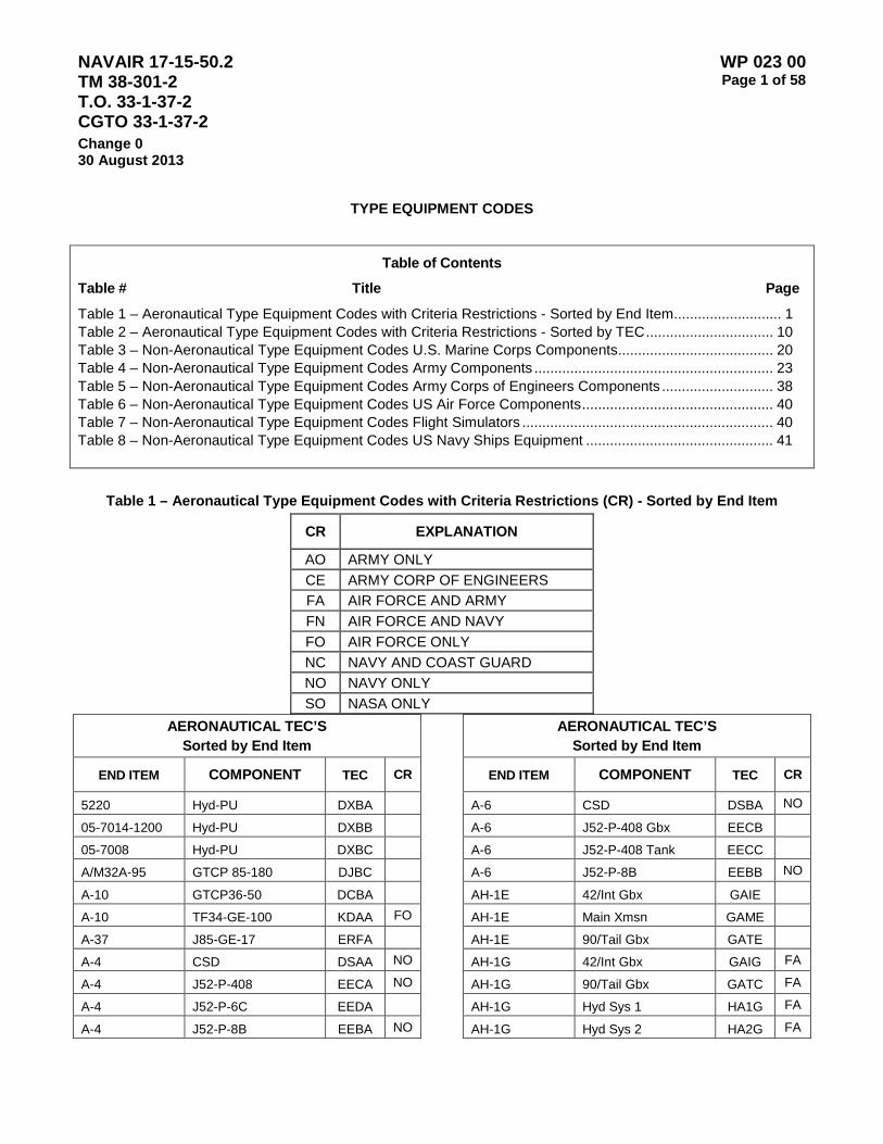
NAVAIR 17-15-50.2 TM 38-301-2 T.O. 33-1-37-2 CGTO 33-1-37-2
WP 023 00 Page 1 of 58
Change 0 30 August 2013
TYPE EQUIPMENT CODES
Table of Contents
Table # Title Page
Table 1 – Aeronautical Type Equipment Codes with Criteria Restrictions - Sorted by End Item........................... 1 Table 2 – Aeronautical Type Equipment Codes with Criteria Restrictions - Sorted by TEC ................................ 10 Table 3 – Non-Aeronautical Type Equipment Codes U.S. Marine Corps Components ....................................... 20 Table 4 – Non-Aeronautical Type Equipment Codes Army Components ............................................................ 23 Table 5 – Non-Aeronautical Type Equipment Codes Army Corps of Engineers Components ............................ 38 Table 6 – Non-Aeronautical Type Equipment Codes US Air Force Components ................................................ 40 Table 7 – Non-Aeronautical Type Equipment Codes Flight Simulators ............................................................... 40 Table 8 – Non-Aeronautical Type Equipment Codes US Navy Ships Equipment ............................................... 41
Table 1 – Aeronautical Type Equipment Codes with Criteria Restrictions (CR) - Sorted by End Item
CR EXPLANATION
AO ARMY ONLY CE ARMY CORP OF ENGINEERS FA AIR FORCE AND ARMY FN AIR FORCE AND NAVY FO AIR FORCE ONLY NC NAVY AND COAST GUARD NO NAVY ONLY SO NASA ONLY
AERONAUTICAL TEC’S Sorted by End Item
END ITEM COMPONENT TEC CR
5220 Hyd-PU DXBA 05-7014-1200 Hyd-PU DXBB 05-7008 Hyd-PU DXBC A/M32A-95 GTCP 85-180 DJBC A-10 GTCP36-50 DCBA A-10 TF34-GE-100 KDAA FO
A-37 J85-GE-17 ERFA A-4 CSD DSAA NO
A-4 J52-P-408 EECA NO
A-4 J52-P-6C EEDA A-4 J52-P-8B EEBA NO
AERONAUTICAL TEC’S Sorted by End Item
END ITEM COMPONENT TEC CR
A-6 CSD DSBA NO
A-6 J52-P-408 Gbx EECB A-6 J52-P-408 Tank EECC A-6 J52-P-8B EEBB NO
AH-1E 42/Int Gbx GAIE AH-1E Main Xmsn GAME AH-1E 90/Tail Gbx GATE AH-1G 42/Int Gbx GAIG FA
AH-1G 90/Tail Gbx GATC FA
AH-1G Hyd Sys 1 HA1G FA
AH-1G Hyd Sys 2 HA2G FA
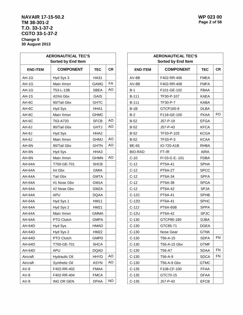
NAVAIR 17-15-50.2 TM 38-301-2 T.O. 33-1-37-2 CGTO 33-1-37-2
WP 023 00 Page 2 of 58
Change 0 30 August 2013
AERONAUTICAL TEC’S Sorted by End Item
END ITEM COMPONENT TEC CR
AH-1G Hyd Sys 3 HA31 AH-1G Main Xmsn GAMG FA
AH-1G T53-L-13B SBEA AO
AH-1S 42/Int Gbx GAIS AH-6C 90/Tail Gbx GHTC AH-6C Hyd Sys HHA1 AH-6C Main Xmsn GHMC AH-6C T63-A720 SFCB AO
AH-6J 90/Tail Gbx GHTJ AO
AH-6J Hyd Sys HHA2 AH-6J Main Xmsn GHMJ AO
AH-6N 90/Tail Gbx GHTN AO
AH-6N Hyd Sys HHA3 AH-6N Main Xmsn GHMN AO
AH-64A T700-GE-701 SHCB AH-64A Int Gbx GMIA AH-64A Tail Gbx GMTA AH-64A #1 Nose Gbx GM1A AH-64A #2 Nose Gbx GM2A AH-64A APU DQAA AH-64A Hyd Sys 1 HM11 AH-64A Hyd Sys 2 HM21 AH-64A Main Xmsn GMMA AH-64A PTO Clutch GMPA AH-64D Hyd Sys HMAD AH-64D Hyd Sys 2 HM22 AH-64D PTO Clutch GMPD AH-64D T700-GE-701 SHCA AH-64D APU DQAD Aircraft Hydraulic Oil HHYD AO
Aircraft Synthetic Oil ASYN AO
AV-8 F402-RR-402 FMAA AV-8 F402-RR-404 FMCA AV-8 ING DR GEN DPAA NO
AERONAUTICAL TEC’S Sorted by End Item
END ITEM COMPONENT TEC CR
AV-8B F402-RR-406 FMEA AV-8B F402-RR-408 FMFA B-1 F101-GE-102 FBAA B-111 TF30-P-107 KAEA B-111 TF30-P-7 KABA B-1B GTCP165-9 DLBA B-2 F118-GE-100 FKAA FO
B-52 J57-P-19 EFGA B-52 J57-P-43 KFCA B-52 TF33-P-103 KCGA B-52 TF33-P-3 KCAA BE-65 IO-720-A1B RHBA BIO-RAD FT-IR AIRA C-10 FI 03-G E- 101 FDBA
C-12 PT5A-41 SPHA
C-12 PT6A-27 SPCC C-12 PT6A-34 SPFA C-12 PT6A-38 SPGA C-12 PT6A-42 SPJA
C-12C PT6A-41 SPHB C-12D PT6A-41 SPHC
C-12J PT6A-65B SPPA C-12U PT6A-42 SPJC C-130 GTCP85-180 DJBA C-130 GTC85-71 DGEA C-130 Nose Gear GTNK C-130 T56-A-15 SDFA FN
C-130 T56-A-15 Gbx GTMF C-130 T56-A7 SDAA FN
C-130 T56-A-9 SDCA FN
C-130 T56-A-9 Gbx GTMC C-135 F108-CF-100 FFAA C-135 GTC70-15 DFAA C-135 J57-P-43 EFCB
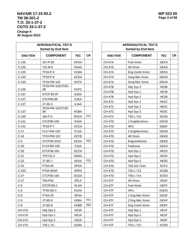
NAVAIR 17-15-50.2 TM 38-301-2 T.O. 33-1-37-2 CGTO 33-1-37-2
WP 023 00 Page 3 of 58
Change 0 30 August 2013
AERONAUTICAL TEC’S Sorted by End Item
END ITEM COMPONENT TEC CR
C-135 J57-P-59 EFDA C-135 T41 M-9 DAAA C-135 TF33-P-5 KCBA C-135 TF33-P-9 KCDA C-135 TF33-PW-102 KCFA
C-135 TF33-PW-102/JT3D–3B KCFC
C-137 GTCP 85-97 DJDA C-137 GTCP85-98 DJEA C-137 JT-3D-3 KJAA
C-137 TF33-PW-102/JT3D-3B KGBA
C-140 J60-P-5 EHCA FO
C-141 GTCP85-106 DJAA C-141 TF33-P-7 KCCA C-17 F117-PW-100 FLAA C-18 TF33-PW-102 KCFB C-2 GTCP36-201C DCAA NO
C-20 F113-RR-100 FJAA C-20 GTCP36-100 DCCA C-21 TFE731-2 KMAA C-22 JT-8D-7 KKAA FO
C-23 PT6A-45 SPKA C-23C PT6A-65AR SPRA C-27 CTCP36-16A DCGA C-27 T64-P4D SPLA C-5 GTCP165-1 DLAA C-5 TF39-GE-1 KGAA C-6 PT6A-20 SPAA C-9 JT-8D-9 KKBA FO
C-9 JT-8D-9 KKBB NO
CH-47A Hdy Sys 3 HE3A CH-47A Hyd Sys 1 HE1A CH-47A Hyd Sys 2 HE2A CH-47A T55-L-7C SCBA
AERONAUTICAL TEC’S Sorted by End Item
END ITEM COMPONENT TEC CR
CH-47A Fwd Xmsn GEFA CH-47A Aft Xmsn GEAA CH-47A Eng Comb Xmsn GEEA CH-47A 1eng Mec Zmsn GEGA CH-47A 2eng Mec Xmsn GEHA CH-47B Hdy Sys 3 HE3B CH-47B Hyd Sys 1 HE1B CH-47B Hyd Sys 2 HE2B CH-47C Hyd Sys 1 HE1C CH-47C Hyd Sys 2 HE2C CH-47C Hyd Sys 3 HE3C CH-47C T55-L-712 SCDA CH-47D 1 EngMecXmsn GEGD CH-47D APU DQAF CH-47D 2 EngMecXmsn GEHD CH-47D Aft Xmsn GEAD CH-47D Engcombxmsn GEED CH-47D Fwdxmsn GEFD CH-47D Hyd Sys 1 HE1D CH-47D Hyd Sys 2 HE2D CH-47D Hyd Sys 3 HE3D CH-47D T55-GA-714A SCFA CH-47D T55-L-712 SCDB CH-47D T55-L-714 SCED CH-47F Aft Xmsn GEAF CH-47F Fwd Xmsn GEFF CH-47F APU DQAG CH-47F 1 Eng Mec Xmsn GEGF CH-47F 2 Eng Mec Xmsn GEHF CH-47F Eng Comb Xmsn GEEF CH-47F Hyd Sys 1 HE1F CH-47F Hyd Sys 2 HE2F CH-47F Hyd Sys 3 HE3F CH-47F T55-L-712 SCDD
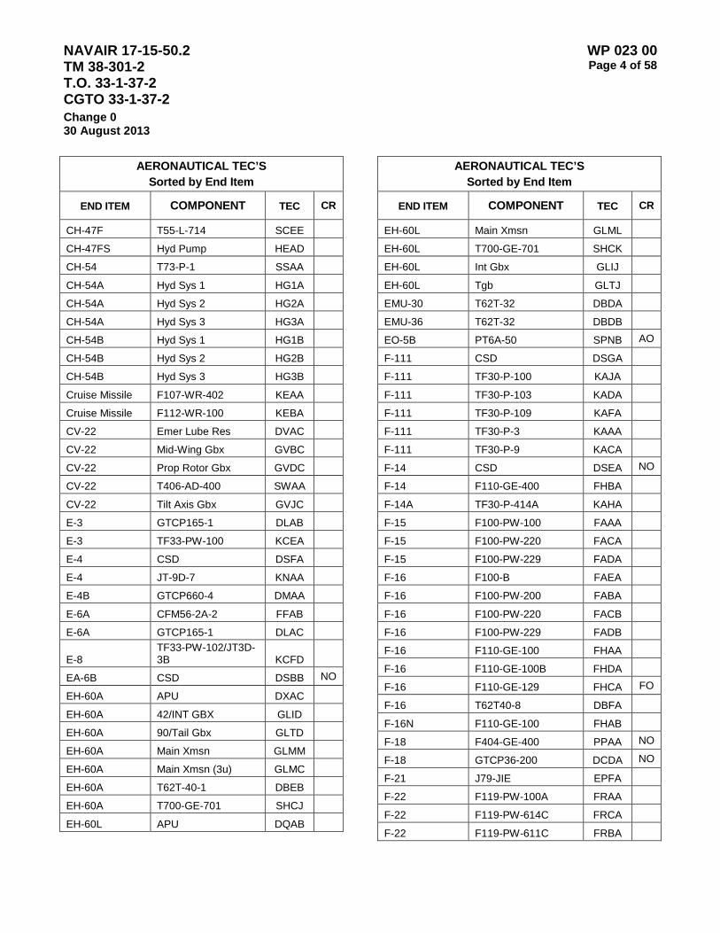
NAVAIR 17-15-50.2 TM 38-301-2 T.O. 33-1-37-2 CGTO 33-1-37-2
WP 023 00 Page 4 of 58
Change 0 30 August 2013
AERONAUTICAL TEC’S Sorted by End Item
END ITEM COMPONENT TEC CR
CH-47F T55-L-714 SCEE CH-47FS Hyd Pump HEAD CH-54 T73-P-1 SSAA CH-54A Hyd Sys 1 HG1A CH-54A Hyd Sys 2 HG2A CH-54A Hyd Sys 3 HG3A CH-54B Hyd Sys 1 HG1B CH-54B Hyd Sys 2 HG2B CH-54B Hyd Sys 3 HG3B
Cruise Missile F107-WR-402 KEAA Cruise Missile F112-WR-100 KEBA CV-22 Emer Lube Res DVAC CV-22 Mid-Wing Gbx GVBC CV-22 Prop Rotor Gbx GVDC CV-22 T406-AD-400 SWAA CV-22 Tilt Axis Gbx GVJC E-3 GTCP165-1 DLAB E-3 TF33-PW-100 KCEA E-4 CSD DSFA E-4 JT-9D-7 KNAA E-4B GTCP660-4 DMAA E-6A CFM56-2A-2 FFAB E-6A GTCP165-1 DLAC
E-8 TF33-PW-102/JT3D-3B KCFD
EA-6B CSD DSBB NO
EH-60A APU DXAC EH-60A 42/INT GBX GLID EH-60A 90/Tail Gbx GLTD EH-60A Main Xmsn GLMM EH-60A Main Xmsn (3u) GLMC EH-60A T62T-40-1 DBEB
EH-60A T700-GE-701 SHCJ
EH-60L APU DQAB
AERONAUTICAL TEC’S Sorted by End Item
END ITEM COMPONENT TEC CR
EH-60L Main Xmsn GLML
EH-60L T700-GE-701 SHCK EH-60L Int Gbx GLIJ EH-60L Tgb GLTJ EMU-30 T62T-32 DBDA EMU-36 T62T-32 DBDB EO-5B PT6A-50 SPNB AO
F-111 CSD DSGA F-111 TF30-P-100 KAJA F-111 TF30-P-103 KADA F-111 TF30-P-109 KAFA F-111 TF30-P-3 KAAA F-111 TF30-P-9 KACA F-14 CSD DSEA NO
F-14 F110-GE-400 FHBA F-14A TF30-P-414A KAHA F-15 F100-PW-100 FAAA F-15 F100-PW-220 FACA F-15 F100-PW-229 FADA F-16 F100-B FAEA F-16 F100-PW-200 FABA F-16 F100-PW-220 FACB F-16 F100-PW-229 FADB F-16 F110-GE-100 FHAA F-16 F110-GE-100B FHDA F-16 F110-GE-129 FHCA FO
F-16 T62T40-8 DBFA F-16N F110-GE-100 FHAB F-18 F404-GE-400 PPAA NO
F-18 GTCP36-200 DCDA NO
F-21 J79-JIE EPFA F-22 F119-PW-100A FRAA F-22 F119-PW-614C FRCA F-22 F119-PW-611C FRBA
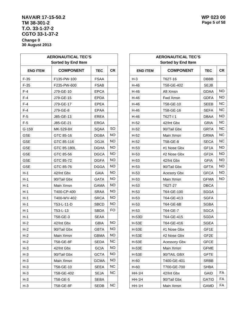
NAVAIR 17-15-50.2 TM 38-301-2 T.O. 33-1-37-2 CGTO 33-1-37-2
WP 023 00 Page 5 of 58
Change 0 30 August 2013
AERONAUTICAL TEC’S Sorted by End Item
END ITEM COMPONENT TEC CR
F-35 F135-PW-100 FSAA
F-35 F235-PW-600 FSAB
F-4 J79-GE-10 EPCA F-4 J79-GE-15 EPDA F-4 J79-GE-17 EPEA F-4 J79-GE-8 EPAA F-5 J85-GE-13 EREA F-5 J85-GE-21 ERGA G-159 MK-529-8X SQAA SO
GSE GTC 85-16 DGBA NO
GSE GTC 85-116 DGJA NO
GSE GTC 85-180L DGHA NO
GSE GTC 85-56 DGCA NO
GSE GTC 85-72 DGFA NO
GSE GTC 85-76 DGGA NO
H-1 42/Int Gbx GAIA NO
H-1 90/Tail Gbx GATA NO
H-1 Main Xmsn GAMA NO
H-1 T400-CP-400 SRAA NO
H-1 T400-WV-402 SRCA NO
H-1 T53-L-11-D SBCD NO
H-1 T53-L-13 SBDA FO
H-1 T58-GE-3 SEAA H-2 42/Int Gbx GBIA NO
H-2 90/Tail Gbx GBTA NO
H-2 Main Xmsn GBMA NO
H-2 T58-GE-8F SEDA NC
H-3 42/Int Gbx GCIA NO
H-3 90/Tail Gbx GCTA NO
H-3 Main Xmsn GCMA NO
H-3 T58-GE-10 SEEA NC
H-3 T58-GE-402 SEJA NC
H-3 T58-GE-5 SEBA H-3 T58-GE-8F SEDB NC
AERONAUTICAL TEC’S Sorted by End Item
END ITEM COMPONENT TEC CR
H-3 T62T-16 DBBB H-46 T58-GE-402 SEJB H-46 Aft Xmsn GDAA NO
H-46 Fwd Xmsn GDFA NO
H-46 T58-GE-10 SEEB NC
H-46 T58-GE-16 SEFA NC
H-46 T62T-l 1 DBAA NO
H-52 42/Int Gbx GRIA NC
H-52 90/Tail Gbx GRTA NC
H-52 Main Xmsn GRMA NC
H-52 T58-GE-8 SECA NC
H-53 #1 Nose Gbx GF1A NO
H-53 #2 Nose Gbx GF2A NO
H-53 42/Int Gbx GFIA NO
H-53 90/Tail Gbx GFTA NO
H-53 Acesory Gbx GFCA NO
H-53 Main Xmsn GFMA NO
H-53 T62T-27 DBCA H-53 T64-GE-100 SGGA H-53 T64-GE-413 SGFA H-53 T64-GE-6B SGBA H-53 T64-GE-7 SGCA H-53D T64-GE-415 SGDA H-53E T64-GE-416 SGEA H-53E #1 Nose Gbx GF1E H-53E #2 Nose Gbx GF2E H-53E Acessory Gbx GFCE H-53E Main Xmsn GFME H-53E 90/TAIL GBX GFTE H-60 T400-GE-401 SRBB H-60 T700-GE-700 SHBA HH-1H 42/Int Gbx GAID FA
HH-1H 90/Tail Gbx GATID FA
HH-1H Main Xmsn GAMD FA
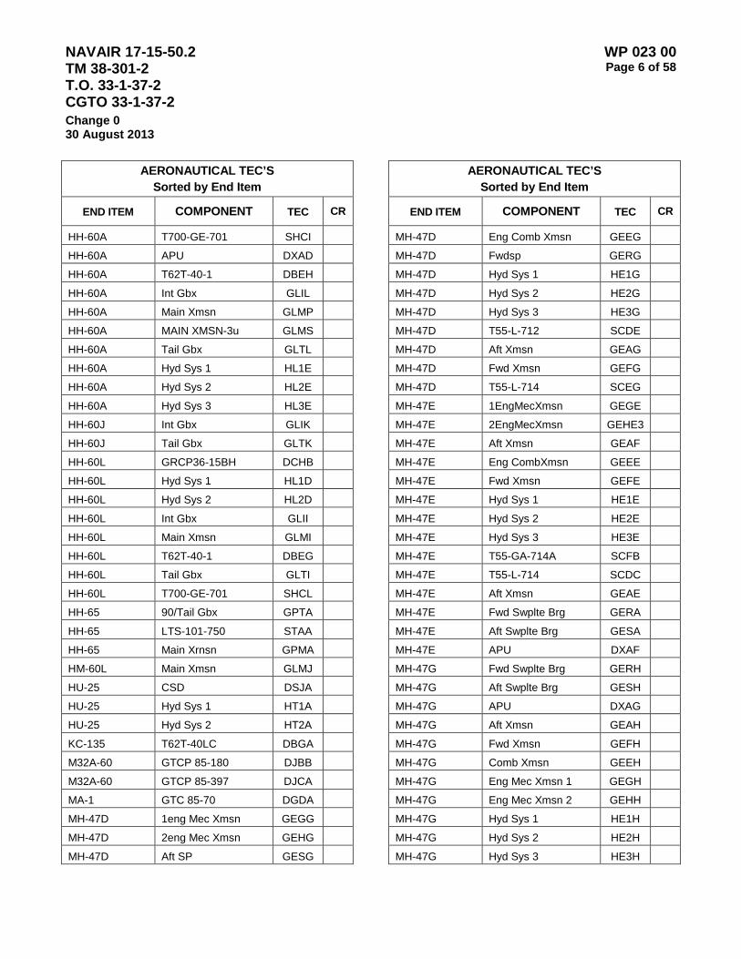
NAVAIR 17-15-50.2 TM 38-301-2 T.O. 33-1-37-2 CGTO 33-1-37-2
WP 023 00 Page 6 of 58
Change 0 30 August 2013
AERONAUTICAL TEC’S Sorted by End Item
END ITEM COMPONENT TEC CR
HH-60A T700-GE-701 SHCI HH-60A APU DXAD HH-60A T62T-40-1 DBEH HH-60A Int Gbx GLIL HH-60A Main Xmsn GLMP HH-60A MAIN XMSN-3u GLMS HH-60A Tail Gbx GLTL HH-60A Hyd Sys 1 HL1E HH-60A Hyd Sys 2 HL2E HH-60A Hyd Sys 3 HL3E HH-60J Int Gbx GLIK HH-60J Tail Gbx GLTK HH-60L GRCP36-15BH DCHB HH-60L Hyd Sys 1 HL1D HH-60L Hyd Sys 2 HL2D HH-60L Int Gbx GLII HH-60L Main Xmsn GLMI HH-60L T62T-40-1 DBEG HH-60L Tail Gbx GLTI HH-60L T700-GE-701 SHCL
HH-65 90/Tail Gbx GPTA HH-65 LTS-101-750 STAA HH-65 Main Xrnsn GPMA HM-60L Main Xmsn GLMJ HU-25 CSD DSJA HU-25 Hyd Sys 1 HT1A HU-25 Hyd Sys 2 HT2A KC-135 T62T-40LC DBGA M32A-60 GTCP 85-180 DJBB M32A-60 GTCP 85-397 DJCA MA-1 GTC 85-70 DGDA MH-47D 1eng Mec Xmsn GEGG MH-47D 2eng Mec Xmsn GEHG
MH-47D Aft SP GESG
AERONAUTICAL TEC’S Sorted by End Item
END ITEM COMPONENT TEC CR
MH-47D Eng Comb Xmsn GEEG MH-47D Fwdsp GERG MH-47D Hyd Sys 1 HE1G MH-47D Hyd Sys 2 HE2G MH-47D Hyd Sys 3 HE3G MH-47D T55-L-712 SCDE MH-47D Aft Xmsn GEAG MH-47D Fwd Xmsn GEFG MH-47D T55-L-714 SCEG MH-47E 1EngMecXmsn GEGE MH-47E 2EngMecXmsn GEHE3 MH-47E Aft Xmsn GEAF MH-47E Eng CombXmsn GEEE MH-47E Fwd Xmsn GEFE MH-47E Hyd Sys 1 HE1E MH-47E Hyd Sys 2 HE2E MH-47E Hyd Sys 3 HE3E MH-47E T55-GA-714A SCFB MH-47E T55-L-714 SCDC MH-47E Aft Xmsn GEAE MH-47E Fwd Swplte Brg GERA MH-47E Aft Swplte Brg GESA MH-47E APU DXAF MH-47G Fwd Swplte Brg GERH MH-47G Aft Swplte Brg GESH MH-47G APU DXAG MH-47G Aft Xmsn GEAH MH-47G Fwd Xmsn GEFH MH-47G Comb Xmsn GEEH MH-47G Eng Mec Xmsn 1 GEGH MH-47G Eng Mec Xmsn 2 GEHH MH-47G Hyd Sys 1 HE1H MH-47G Hyd Sys 2 HE2H MH-47G Hyd Sys 3 HE3H
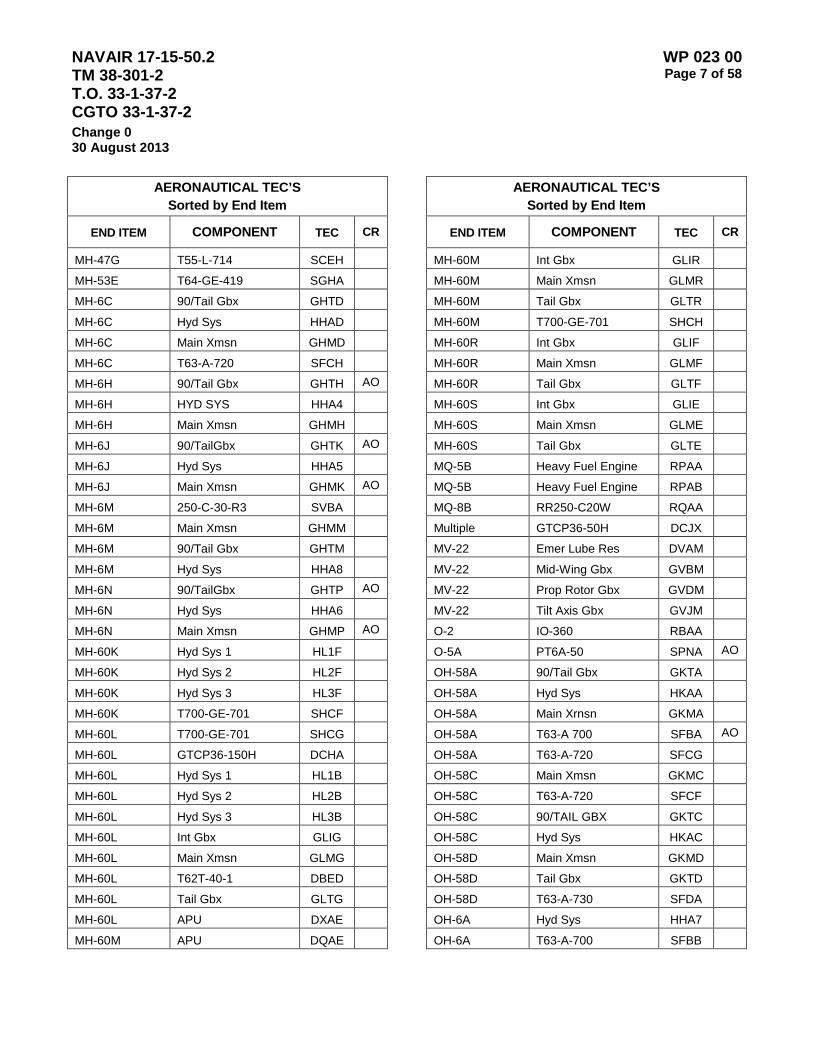
NAVAIR 17-15-50.2 TM 38-301-2 T.O. 33-1-37-2 CGTO 33-1-37-2
WP 023 00 Page 7 of 58
Change 0 30 August 2013
AERONAUTICAL TEC’S Sorted by End Item
END ITEM COMPONENT TEC CR
MH-47G T55-L-714 SCEH MH-53E T64-GE-419 SGHA MH-6C 90/Tail Gbx GHTD MH-6C Hyd Sys HHAD MH-6C Main Xmsn GHMD MH-6C T63-A-720 SFCH MH-6H 90/Tail Gbx GHTH AO
MH-6H HYD SYS HHA4 MH-6H Main Xmsn GHMH MH-6J 90/TailGbx GHTK AO
MH-6J Hyd Sys HHA5 MH-6J Main Xmsn GHMK AO
MH-6M 250-C-30-R3 SVBA MH-6M Main Xmsn GHMM MH-6M 90/Tail Gbx GHTM MH-6M Hyd Sys HHA8 MH-6N 90/TailGbx GHTP AO
MH-6N Hyd Sys HHA6 MH-6N Main Xmsn GHMP AO
MH-60K Hyd Sys 1 HL1F MH-60K Hyd Sys 2 HL2F MH-60K Hyd Sys 3 HL3F MH-60K T700-GE-701 SHCF MH-60L T700-GE-701 SHCG MH-60L GTCP36-150H DCHA MH-60L Hyd Sys 1 HL1B MH-60L Hyd Sys 2 HL2B MH-60L Hyd Sys 3 HL3B MH-60L Int Gbx GLIG MH-60L Main Xmsn GLMG MH-60L T62T-40-1 DBED MH-60L Tail Gbx GLTG MH-60L APU DXAE MH-60M APU DQAE
AERONAUTICAL TEC’S Sorted by End Item
END ITEM COMPONENT TEC CR
MH-60M Int Gbx GLIR MH-60M Main Xmsn GLMR MH-60M Tail Gbx GLTR MH-60M T700-GE-701 SHCH MH-60R Int Gbx GLIF MH-60R Main Xmsn GLMF MH-60R Tail Gbx GLTF MH-60S Int Gbx GLIE MH-60S Main Xmsn GLME MH-60S Tail Gbx GLTE MQ-5B Heavy Fuel Engine RPAA MQ-5B Heavy Fuel Engine RPAB MQ-8B RR250-C20W RQAA Multiple GTCP36-50H DCJX MV-22 Emer Lube Res DVAM MV-22 Mid-Wing Gbx GVBM MV-22 Prop Rotor Gbx GVDM MV-22 Tilt Axis Gbx GVJM O-2 IO-360 RBAA O-5A PT6A-50 SPNA AO
OH-58A 90/Tail Gbx GKTA OH-58A Hyd Sys HKAA OH-58A Main Xrnsn GKMA OH-58A T63-A 700 SFBA AO
OH-58A T63-A-720 SFCG OH-58C Main Xmsn GKMC OH-58C T63-A-720 SFCF OH-58C 90/TAIL GBX GKTC OH-58C Hyd Sys HKAC OH-58D Main Xmsn GKMD OH-58D Tail Gbx GKTD OH-58D T63-A-730 SFDA OH-6A Hyd Sys HHA7 OH-6A T63-A-700 SFBB

NAVAIR 17-15-50.2 TM 38-301-2 T.O. 33-1-37-2 CGTO 33-1-37-2
WP 023 00 Page 8 of 58
Change 0 30 August 2013
AERONAUTICAL TEC’S Sorted by End Item
END ITEM COMPONENT TEC CR
OH-6A Main Xmsn GHMA OH-6A 90/TAIL GBX GHTA Oil Cart PON-6 DRAA Oil-Lube MIL-H-5606 A007 Oil-Lube MIL-H-83282 A006 Oil-Lube MIL-L-23699 A001 Oil-Lube MIL-L-7808 A003 Oil-Lube MIL-L-85734 A005 Oil-Lube MIL-PRF23699 A002 Oil-Lube MIL-PRF85734 A004 OV-10 T76-G-10 SMAA OV-10 T76-G-12 SMBA OV-10 T76-G-418 SMCA OV-10 T76-G-419 SMDA OV-10 T76-G-420 SMEA OV-10 T76-G-421 SMFA P-3 GTCP 95-2 DKAA NO
Predator TPE331-10 SJAA QF-86F J47-GE-27 ECAA RC-12D PT6A-41 SPHD RC-12G PT6A-41 SPHE RC-12K PT6A-67 SPMA RC-12P PT6A-41 SPHG RC-12Q PT6A-41 SPHH RQ-5A Main Gbx GNMA RQ-5A V-75 RNAA RU-9D O-480-B1A6 RDEA S-3 GTCP36-201A DCAB NO
S-3 TF34-GE-400B KDBA NO
SH-2G #1 Nose Gbx GB1G NO
SH-2G #2 Nose Gbx GB2G NO
SH-2G 42/Int Gbx GBIG NO
SH-2G 90/Tail Gbx GBTG NO
SH-2G Acesory Gbx GBCG NO
AERONAUTICAL TEC’S Sorted by End Item
END ITEM COMPONENT TEC CR
SH-2G Main Xmsn GBMG NO
SH-60B 42/Int Gbx GLIB SH-60B 90/Tail Gbx GLTB SH-60B Main Xmsn GLMB SH-60F Main GBX GQMB SH-60F Tail GBX GQTB SH-60F Int GBX GQIB T-1A JT15D-5B KPAA T-2 J85-GE-4 ERBA T-2C J85-GE-4A ERCA T-34 PT6A-42 SPJB T-34B O-470 RCAA NO
T-34C Brake Sys HNBC T-34C PT6A-25 SPBA NO
T-37 J69-T-25 EKAA T-38 J85-GE-5 ERDA T-39 J60-P-3 EHAA FO
T-39 J60-P-3A EHBA NO
T-39 JT-12A-8 KLAA NO
T-41 IO-360 RBAB T-41 O-300D RLAA T-41B IO-360-D RBCA T-41C IO-360-C RBBA T-41C IO-360-D RBCB T-41D IO-360-D RBCC T-43 JT-8D-9 KKBC FO
T-44A PT6A-34B SPFB NO
T-45A F405-RR-400 FQAA T-46 F109-GA-100 FGAA T-6A PT6A-68 SPQA Test Cell GTCP 95-3 DKBA NO
Test Cell T56-A-10 SDDX FN
Test Cell T56-A-14 SDEX FN
Test Cell T56-A-16 SDGX FN

NAVAIR 17-15-50.2 TM 38-301-2 T.O. 33-1-37-2 CGTO 33-1-37-2
WP 023 00 Page 9 of 58
Change 0 30 August 2013
AERONAUTICAL TEC’S Sorted by End Item
END ITEM COMPONENT TEC CR
Test Cell T56-A-425 SDHX FN
Test Cell T56-A-426 SDJX FN
Test Cell T56-A-7B SDBX FN
Test Cell T62T-16 DBBA Test Cell T700-GE-401 SHAX TG-7 O-235 RAAA TH-1G Hyd Sys 3 HA32 TH-57B 90/Tail Gbx GSTB NO
TH-57B Main Xmsn GSMB NO
TH-57B T63-A-720 SFCA NO
TH-67 250-C-30 SVAA TH-67 90/TAIL GBX GUTA TH-67 Hyd Sys HUAA TH-67 Main Xmsn GUMA U-10 GO-480-G1D6 RDHA U-2 J57-P-31 EFBA U-2 J75-P-17 EMAB U-21F PT6A-28 SPDA U-21G T74-CP-700 SUAF U-2S F118-GE-101 EMAC UH-1B 42/Int Gbx GAIB FA
UH-1B 90/Tail Gbx GATB FA
UH-1B Hyd Sys HAAB FA
UH-1B Main Xmsn GAMB FA
UH-1B T53-L-11 SBCA AO
UH-1C 42/Int Gbx GAIC FA
UH-1C 90/Tail Gbx GATC FA
UH-1C Hyd Sys HAAC FA
UH-1C Main Xmsn GAMC FA
UH-1C T53-L-11 SBCB AO
UH-1FS Hyd Pump HAA1 UH-1H 42/Int Gbx GAIH FA
UH-1H 90/Tail Gbx GATH FA
UH-1H Hyd Sys HAAH FA
AERONAUTICAL TEC’S Sorted by End Item
END ITEM COMPONENT TEC CR
UH-1H Main Xmsn GAMH FA
UH-1H T53-L-13B SBEE AO
UH-1M 42/Int Gbx GAIM FA
UH-1M 90/Tail Gbx GATM FA
UH-1M Hyd Sys 1 HA1M FA
UH-1M Hyd Sys 2 HA2M FA
UH-1M Main Xmsn GAMM FA
UH-1M T53-L-13B SBEF AO
UH-1N 42/Int Gbx GAIN FA
UH-1N 90/Tail Gbx GATN FA
UH-1N Eng Comb Gbx GAEN FN
UH-1N Hyd Sys HAA4 UH-1N Main Xmsn GAMN FA
UH-1N T400-CP-400 SRAB UH-1V 42/Int Gbx GAIV FA
UH-1V 90/Tail Gbx GATN FA
UH-1V Hyd Sys HAAV FA
UH-1V Main Xmsn GAMV FA
UH-1V T53-L-11 SBCC AO
UH-1V T53-L-13B SBEG AO
UH-1X 42/Int Gbx GAIX FA
UH-1X 90/Tail Gbx GATX FA
UH-1X Hyd Sys HAAX FA
UH-1X Main Xmsn GAMX FA
UH-60 Hyd-Pump HLPA UH-60A T700-GE-701 SHCC UH-60A 90/Tail Gbx GLTI UH-60A Main Xmsn GLMK UH-60A Main Xmsn (3u) GLMA UH-60A T62T-40-1 DBEA UH-60A Int Gbx GLIA
UH-60A 90/Tail Gbx GLTA
UH-60A APU DXAA
UH-60FS Hyd Pump HLAA

NAVAIR 17-15-50.2 TM 38-301-2 T.O. 33-1-37-2 CGTO 33-1-37-2
WP 023 00 Page 10 of 58
Change 0 30 August 2013
AERONAUTICAL TEC’S Sorted by End Item
END ITEM COMPONENT TEC CR
UH-60L T700-GE-701 SHCD UH-60L GTC36-150 DCEA UH-60L 42/Int Gbx GLIC UH-60L Hyd Sys 1 HL12 UH-60L T62T-40-1 DBEC UH-60L T700-GE-701C SHDA UH-60L Main Xmsn GLMD UH-60L Main Gbx GLMD UH-60L 90/Tail Gbx GLTC UH-60L APU DXAB UH-60L Hyd Sys GLTC UH-60M APU DQAC UH-60M Int Gbx GLIM UH-60M Main Xmsn GLMQ UH-60M Tail Gbx GLTM UH-60M T700-GE-701 SHCE UH-60Q Hyd Sys 1 HL1C
AERONAUTICAL TEC’S Sorted by End Item
END ITEM COMPONENT TEC CR
UH-60Q Hyd Sys 2 HL2C UH-60Q Hyd Sys 3 HL3C UH-60Q Main Xmsn (3u) GLMH UH-60Q Tail Gbx GLTH UV-18 PT6A-27 SPCA UV-18A PT6A-27 SPCB VC-140 GTCP 30-92 DNAA VH-3D 42/Int Gbx GCID NO
VH-3D 90/Tail Gbx GCTD NO
VH-3D Hyd Sys HCA1 VH-3D Main Xmsn GCMD NO
VH-3D T58-GE-400 SEGA NC
VH-3D T58-GE-400B SEHA NC
VH-60N Main Xmsn GLMT VH-60N Int Gbx GLTT VH-60N Tail Gbx GLIT
Table 2 – Aeronautical Type Equipment Codes with Criteria Restrictions Sorted by TEC
CR EXPLANATION
AO ARMY ONLY CE ARMY CORP OF ENGINEERS FA AIR FORCE AND ARMY FN AIR FORCE AND NAVY FO AIR FORCE ONLY NC NAVY AND COAST GUARD NO NAVY ONLY SO NASA ONLY
AERONAUTICAL TEC’S Sorted by TEC
END ITEM COMPONENT TEC CR
Oil-Lube MIL-L-23699 A001 Oil-Lube MIL-PRF23699 A002
AERONAUTICAL TEC’S Sorted by TEC
END ITEM COMPONENT TEC CR
Oil-Lube MIL-L-7808 A003 Oil-Lube MIL-PRF85734 A004

NAVAIR 17-15-50.2 TM 38-301-2 T.O. 33-1-37-2 CGTO 33-1-37-2
WP 023 00 Page 11 of 58
Change 0 30 August 2013
AERONAUTICAL TEC’S Sorted by TEC
END ITEM COMPONENT TEC CR
Oil-Lube MIL-L-85734 A005 Oil-Lube MIL-H-83282 A006 Oil-Lube MIL-H-5606 A007 BIO-RAD FT-IR AIRA Aircraft Synthetic Oil ASYN AO
C-135 T41 M-9 DAAA H-46 T62T-l 1 DBAA NO
Test Cell T62T-16 DBBA H-3 T62T-16 DBBB H-53 T62T-27 DBCA EMU-30 T62T-32 DBDA EMU-36 T62T-32 DBDB UH-60A T62T-40-1 DBEA EH-60A T62T-40-1 DBEB UH-60L T62T-40-1 DBEC MH-60L T62T-40-1 DBED HH-60L T62T-40-1 DBEG HH-60A T62T-40-1 DBEH F-16 T62T40-8 DBFA KC-135 T62T-40LC DBGA C-2 GTCP36-201C DCAA NO
S-3 GTCP36-201A DCAB NO
A-10 GTCP36-50 DCBA C-20 GTCP36-100 DCCA F-18 GTCP36-200 DCDA NO
UH-60L GTC36-150 DCEA C-27 CTCP36-16A DCGA MH-60L GTCP36-150H DCHA HH-60L GRCP36-15BH DCHB Multiple GTCP36-50H DCJX C-135 GTC70-15 DFAA GSE GTC 85-16 DGBA NO
GSE GTC 85-56 DGCA NO
AERONAUTICAL TEC’S Sorted by TEC
END ITEM COMPONENT TEC CR
MA-1 GTC 85-70 DGDA C-130 GTC85-71 DGEA GSE GTC 85-72 DGFA NO
GSE GTC 85-76 DGGA NO
GSE GTC 85-180L DGHA NO
GSE GTC 85-116 DGJA NO
C-141 GTCP85-106 DJAA C-130 GTCP85-180 DJBA M32A-60 GTCP 85-180 DJBB A/M32A-95 GTCP 85-180 DJBC M32A-60 GTCP 85-397 DJCA C-137 GTCP 85-97 DJDA C-137 GTCP85-98 DJEA P-3 GTCP 95-2 DKAA NO
Test Cell GTCP 95-3 DKBA NO
C-5 GTCP165-1 DLAA E-3 GTCP165-1 DLAB E-6A GTCP165-1 DLAC B-1B GTCP165-9 DLBA E-4B GTCP660-4 DMAA VC-140 GTCP 30-92 DNAA AV-8 ING DR GEN DPAA NO
AH-64A APU DQAA EH-60L APU DQAB UH-60M APU DQAC AH-64D APU DQAD MH-60M APU DQAE CH-47D APU DQAF CH-47F APU DQAG Oil Cart PON-6 DRAA A-4 CSD DSAA NO
A-6 CSD DSBA NO
EA-6B CSD DSBB NO
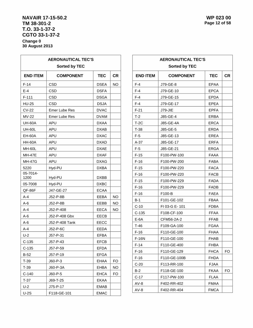
NAVAIR 17-15-50.2 TM 38-301-2 T.O. 33-1-37-2 CGTO 33-1-37-2
WP 023 00 Page 12 of 58
Change 0 30 August 2013
AERONAUTICAL TEC’S Sorted by TEC
END ITEM COMPONENT TEC CR
F-14 CSD DSEA NO
E-4 CSD DSFA F-111 CSD DSGA HU-25 CSD DSJA CV-22 Emer Lube Res DVAC MV-22 Emer Lube Res DVAM UH-60A APU DXAA UH-60L APU DXAB EH-60A APU DXAC HH-60A APU DXAD MH-60L APU DXAE MH-47E APU DXAF MH-47G APU DXAG 5220 Hyd-PU DXBA 05-7014-
1200 Hyd-PU DXBB 05-7008 Hyd-PU DXBC QF-86F J47-GE-27 ECAA A-4 J52-P-8B EEBA NO
A-6 J52-P-8B EEBB NO
A-4 J52-P-408 EECA NO
A-6 J52-P-408 Gbx EECB A-6 J52-P-408 Tank EECC A-4 J52-P-6C EEDA U-2 J57-P-31 EFBA C-135 J57-P-43 EFCB C-135 J57-P-59 EFDA B-52 J57-P-19 EFGA T-39 J60-P-3 EHAA FO
T-39 J60-P-3A EHBA NO
C-140 J60-P-5 EHCA FO
T-37 J69-T-25 EKAA U-2 J75-P-17 EMAB U-2S F118-GE-101 EMAC
AERONAUTICAL TEC’S Sorted by TEC
END ITEM COMPONENT TEC CR
F-4 J79-GE-8 EPAA F-4 J79-GE-10 EPCA F-4 J79-GE-15 EPDA F-4 J79-GE-17 EPEA F-21 J79-JIE EPFA T-2 J85-GE-4 ERBA T-2C J85-GE-4A ERCA T-38 J85-GE-5 ERDA F-5 J85-GE-13 EREA A-37 J85-GE-17 ERFA F-5 J85-GE-21 ERGA F-15 F100-PW-100 FAAA F-16 F100-PW-200 FABA F-15 F100-PW-220 FACA F-16 F100-PW-220 FACB F-15 F100-PW-229 FADA F-16 F100-PW-229 FADB F-16 F100-B FAEA B-1 F101-GE-102 FBAA C-10 FI 03-G E- 101 FDBA C-135 F108-CF-100 FFAA E-6A CFM56-2A-2 FFAB T-46 F109-GA-100 FGAA F-16 F110-GE-100 FHAA F-16N F110-GE-100 FHAB F-14 F110-GE-400 FHBA F-16 F110-GE-129 FHCA FO
F-16 F110-GE-100B FHDA C-20 F113-RR-100 FJAA B-2 F118-GE-100 FKAA FO
C-17 F117-PW-100 FLAA AV-8 F402-RR-402 FMAA AV-8 F402-RR-404 FMCA
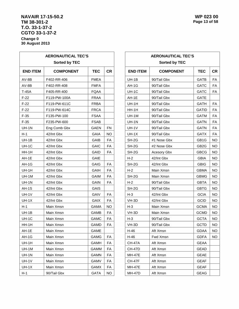
NAVAIR 17-15-50.2 TM 38-301-2 T.O. 33-1-37-2 CGTO 33-1-37-2
WP 023 00 Page 13 of 58
Change 0 30 August 2013
AERONAUTICAL TEC’S Sorted by TEC
END ITEM COMPONENT TEC CR
AV-8B F402-RR-406 FMEA AV-8B F402-RR-408 FMFA T-45A F405-RR-400 FQAA F-22 F119-PW-100A FRAA F-22 F119-PW-611C FRBA F-22 F119-PW-614C FRCA F-35 F135-PW-100 FSAA F-35 F235-PW-600 FSAB UH-1N Eng Comb Gbx GAEN FN
H-1 42/Int Gbx GAIA NO
UH-1B 42/Int Gbx GAIB FA
UH-1C 42/Int Gbx GAIC FA
HH-1H 42/Int Gbx GAID FA
AH-1E 42/Int Gbx GAIE AH-1G 42/Int Gbx GAIG FA
UH-1H 42/Int Gbx GAIH FA
UH-1M 42/Int Gbx GAIM FA
UH-1N 42/Int Gbx GAIN FA
AH-1S 42/Int Gbx GAIS UH-1V 42/Int Gbx GAIV FA
UH-1X 42/Int Gbx GAIX FA
H-1 Main Xmsn GAMA NO
UH-1B Main Xmsn GAMB FA
UH-1C Main Xmsn GAMC FA
HH-1H Main Xmsn GAMD FA
AH-1E Main Xmsn GAME AH-1G Main Xmsn GAMG FA
UH-1H Main Xmsn GAMH FA
UH-1M Main Xmsn GAMM FA
UH-1N Main Xmsn GAMN FA
UH-1V Main Xmsn GAMV FA
UH-1X Main Xmsn GAMX FA
H-1 90/Tail Gbx GATA NO
AERONAUTICAL TEC’S Sorted by TEC
END ITEM COMPONENT TEC CR
UH-1B 90/Tail Gbx GATB FA
AH-1G 90/Tail Gbx GATC FA
UH-1C 90/Tail Gbx GATC FA
AH-1E 90/Tail Gbx GATE UH-1H 90/Tail Gbx GATH FA
HH-1H 90/Tail Gbx GATID FA
UH-1M 90/Tail Gbx GATM FA
UH-1N 90/Tail Gbx GATN FA
UH-1V 90/Tail Gbx GATN FA
UH-1X 90/Tail Gbx GATX FA
SH-2G #1 Nose Gbx GB1G NO
SH-2G #2 Nose Gbx GB2G NO
SH-2G Acesory Gbx GBCG NO
H-2 42/Int Gbx GBIA NO
SH-2G 42/Int Gbx GBIG NO
H-2 Main Xmsn GBMA NO
SH-2G Main Xmsn GBMG NO
H-2 90/Tail Gbx GBTA NO
SH-2G 90/Tail Gbx GBTG NO
H-3 42/Int Gbx GCIA NO
VH-3D 42/Int Gbx GCID NO
H-3 Main Xmsn GCMA NO
VH-3D Main Xmsn GCMD NO
H-3 90/Tail Gbx GCTA NO
VH-3D 90/Tail Gbx GCTD NO
H-46 Aft Xmsn GDAA NO
H-46 Fwd Xmsn GDFA NO
CH-47A Aft Xmsn GEAA CH-47D Aft Xmsn GEAD MH-47E Aft Xmsn GEAE CH-47F Aft Xmsn GEAF MH-47E Aft Xmsn GEAF MH-47D Aft Xmsn GEAG

NAVAIR 17-15-50.2 TM 38-301-2 T.O. 33-1-37-2 CGTO 33-1-37-2
WP 023 00 Page 14 of 58
Change 0 30 August 2013
AERONAUTICAL TEC’S Sorted by TEC
END ITEM COMPONENT TEC CR
MH-47G Aft Xmsn GEAH CH-47A Eng Comb Xmsn GEEA CH-47D Engcombxmsn GEED MH-47E Eng CombXmsn GEEE CH-47F Eng Comb Xmsn GEEF MH-47D Eng Comb Xmsn GEEG MH-47G Comb Xmsn GEEH CH-47A Fwd Xmsn GEFA CH-47D Fwdxmsn GEFD MH-47E Fwd Xmsn GEFE CH-47F Fwd Xmsn GEFF MH-47D Fwd Xmsn GEFG MH-47G Fwd Xmsn GEFH CH-47A 1eng Mec Zmsn GEGA CH-47D 1 EngMecXmsn GEGD MH-47E 1EngMecXmsn GEGE CH-47F 1 Eng Mec Xmsn GEGF MH-47D 1eng Mec Xmsn GEGG MH-47G Eng Mec Xmsn 1 GEGH CH-47A 2eng Mec Xmsn GEHA CH-47D 2 EngMecXmsn GEHD MH-47E 2EngMecXmsn GEHE3 CH-47F 2 Eng Mec Xmsn GEHF MH-47D 2eng Mec Xmsn GEHG MH-47G Eng Mec Xmsn 2 GEHH MH-47E Fwd Swplte Brg GERA MH-47D Fwdsp GERG MH-47G Fwd Swplte Brg GERH MH-47E Aft Swplte Brg GESA MH-47D Aft SP GESG MH-47G Aft Swplte Brg GESH H-53 #1 Nose Gbx GF1A NO
H-53E #1 Nose Gbx GF1E
AERONAUTICAL TEC’S Sorted by TEC
END ITEM COMPONENT TEC CR
H-53 #2 Nose Gbx GF2A NO
H-53E #2 Nose Gbx GF2E H-53 Acesory Gbx GFCA NO
H-53E Acessory Gbx GFCE H-53 42/Int Gbx GFIA NO
H-53 Main Xmsn GFMA NO
H-53E Main Xmsn GFME H-53 90/Tail Gbx GFTA NO
H-53E 90/TAIL GBX GFTE OH-6A Main Xmsn GHMA AH-6C Main Xmsn GHMC MH-6C Main Xmsn GHMD MH-6H Main Xmsn GHMH AH-6J Main Xmsn GHMJ AO
MH-6J Main Xmsn GHMK AO
MH-6M Main Xmsn GHMM AH-6N Main Xmsn GHMN AO
MH-6N Main Xmsn GHMP AO
OH-6A 90/TAIL GBX GHTA AH-6C 90/Tail Gbx GHTC MH-6C 90/Tail Gbx GHTD MH-6H 90/Tail Gbx GHTH AO
AH-6J 90/Tail Gbx GHTJ AO
MH-6J 90/TailGbx GHTK AO
MH-6M 90/Tail Gbx GHTM AH-6N 90/Tail Gbx GHTN AO
MH-6N 90/TailGbx GHTP AO
OH-58A Main Xrnsn GKMA OH-58C Main Xmsn GKMC OH-58D Main Xmsn GKMD OH-58A 90/Tail Gbx GKTA OH-58C 90/TAIL GBX GKTC OH-58D Tail Gbx GKTD
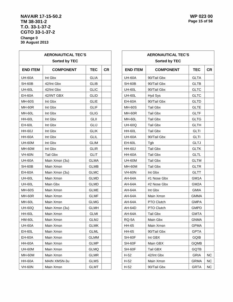
NAVAIR 17-15-50.2 TM 38-301-2 T.O. 33-1-37-2 CGTO 33-1-37-2
WP 023 00 Page 15 of 58
Change 0 30 August 2013
AERONAUTICAL TEC’S Sorted by TEC
END ITEM COMPONENT TEC CR
UH-60A Int Gbx GLIA SH-60B 42/Int Gbx GLIB UH-60L 42/Int Gbx GLIC EH-60A 42/INT GBX GLID MH-60S Int Gbx GLIE MH-60R Int Gbx GLIF MH-60L Int Gbx GLIG HH-60L Int Gbx GLII EH-60L Int Gbx GLIJ HH-60J Int Gbx GLIK HH-60A Int Gbx GLIL UH-60M Int Gbx GLIM MH-60M Int Gbx GLIR VH-60N Tail Gbx GLIT UH-60A Main Xmsn (3u) GLMA SH-60B Main Xmsn GLMB EH-60A Main Xmsn (3u) GLMC UH-60L Main Xmsn GLMD UH-60L Main Gbx GLMD MH-60S Main Xmsn GLME MH-60R Main Xmsn GLMF MH-60L Main Xmsn GLMG UH-60Q Main Xmsn (3u) GLMH HH-60L Main Xmsn GLMI HM-60L Main Xmsn GLMJ UH-60A Main Xmsn GLMK EH-60L Main Xmsn GLML EH-60A Main Xmsn GLMM HH-60A Main Xmsn GLMP UH-60M Main Xmsn GLMQ MH-60M Main Xmsn GLMR HH-60A MAIN XMSN-3u GLMS VH-60N Main Xmsn GLMT
AERONAUTICAL TEC’S Sorted by TEC
END ITEM COMPONENT TEC CR
UH-60A 90/Tail Gbx GLTA SH-60B 90/Tail Gbx GLTB UH-60L 90/Tail Gbx GLTC UH-60L Hyd Sys GLTC EH-60A 90/Tail Gbx GLTD MH-60S Tail Gbx GLTE MH-60R Tail Gbx GLTF MH-60L Tail Gbx GLTG UH-60Q Tail Gbx GLTH HH-60L Tail Gbx GLTI UH-60A 90/Tail Gbx GLTI EH-60L Tgb GLTJ HH-60J Tail Gbx GLTK HH-60A Tail Gbx GLTL UH-60M Tail Gbx GLTM MH-60M Tail Gbx GLTR VH-60N Int Gbx GLTT AH-64A #1 Nose Gbx GM1A AH-64A #2 Nose Gbx GM2A AH-64A Int Gbx GMIA AH-64A Main Xmsn GMMA AH-64A PTO Clutch GMPA AH-64D PTO Clutch GMPD AH-64A Tail Gbx GMTA RQ-5A Main Gbx GNMA HH-65 Main Xrnsn GPMA HH-65 90/Tail Gbx GPTA SH-60F Int GBX GQIB SH-60F Main GBX GQMB SH-60F Tail GBX GQTB H-52 42/Int Gbx GRIA NC
H-52 Main Xmsn GRMA NC
H-52 90/Tail Gbx GRTA NC
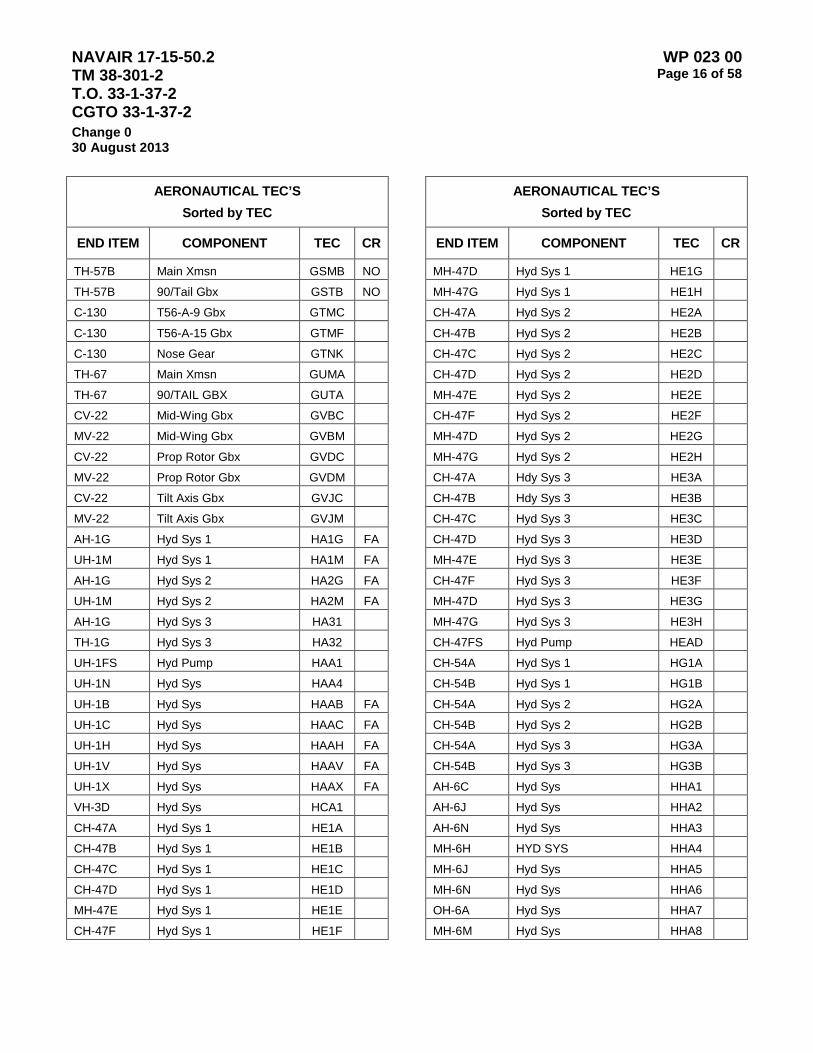
NAVAIR 17-15-50.2 TM 38-301-2 T.O. 33-1-37-2 CGTO 33-1-37-2
WP 023 00 Page 16 of 58
Change 0 30 August 2013
AERONAUTICAL TEC’S Sorted by TEC
END ITEM COMPONENT TEC CR
TH-57B Main Xmsn GSMB NO
TH-57B 90/Tail Gbx GSTB NO
C-130 T56-A-9 Gbx GTMC C-130 T56-A-15 Gbx GTMF C-130 Nose Gear GTNK TH-67 Main Xmsn GUMA TH-67 90/TAIL GBX GUTA CV-22 Mid-Wing Gbx GVBC MV-22 Mid-Wing Gbx GVBM CV-22 Prop Rotor Gbx GVDC MV-22 Prop Rotor Gbx GVDM CV-22 Tilt Axis Gbx GVJC MV-22 Tilt Axis Gbx GVJM AH-1G Hyd Sys 1 HA1G FA
UH-1M Hyd Sys 1 HA1M FA
AH-1G Hyd Sys 2 HA2G FA
UH-1M Hyd Sys 2 HA2M FA
AH-1G Hyd Sys 3 HA31 TH-1G Hyd Sys 3 HA32 UH-1FS Hyd Pump HAA1 UH-1N Hyd Sys HAA4 UH-1B Hyd Sys HAAB FA
UH-1C Hyd Sys HAAC FA
UH-1H Hyd Sys HAAH FA
UH-1V Hyd Sys HAAV FA
UH-1X Hyd Sys HAAX FA
VH-3D Hyd Sys HCA1 CH-47A Hyd Sys 1 HE1A CH-47B Hyd Sys 1 HE1B CH-47C Hyd Sys 1 HE1C CH-47D Hyd Sys 1 HE1D MH-47E Hyd Sys 1 HE1E
CH-47F Hyd Sys 1 HE1F
AERONAUTICAL TEC’S Sorted by TEC
END ITEM COMPONENT TEC CR
MH-47D Hyd Sys 1 HE1G MH-47G Hyd Sys 1 HE1H CH-47A Hyd Sys 2 HE2A CH-47B Hyd Sys 2 HE2B CH-47C Hyd Sys 2 HE2C CH-47D Hyd Sys 2 HE2D MH-47E Hyd Sys 2 HE2E CH-47F Hyd Sys 2 HE2F MH-47D Hyd Sys 2 HE2G MH-47G Hyd Sys 2 HE2H CH-47A Hdy Sys 3 HE3A CH-47B Hdy Sys 3 HE3B CH-47C Hyd Sys 3 HE3C CH-47D Hyd Sys 3 HE3D MH-47E Hyd Sys 3 HE3E CH-47F Hyd Sys 3 HE3F MH-47D Hyd Sys 3 HE3G MH-47G Hyd Sys 3 HE3H CH-47FS Hyd Pump HEAD CH-54A Hyd Sys 1 HG1A CH-54B Hyd Sys 1 HG1B CH-54A Hyd Sys 2 HG2A CH-54B Hyd Sys 2 HG2B CH-54A Hyd Sys 3 HG3A CH-54B Hyd Sys 3 HG3B AH-6C Hyd Sys HHA1 AH-6J Hyd Sys HHA2 AH-6N Hyd Sys HHA3 MH-6H HYD SYS HHA4 MH-6J Hyd Sys HHA5 MH-6N Hyd Sys HHA6 OH-6A Hyd Sys HHA7 MH-6M Hyd Sys HHA8
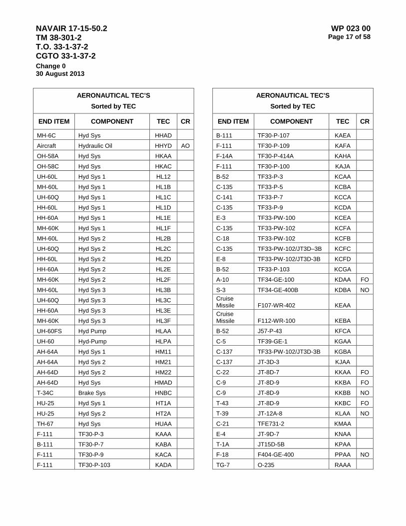
NAVAIR 17-15-50.2 TM 38-301-2 T.O. 33-1-37-2 CGTO 33-1-37-2
WP 023 00 Page 17 of 58
Change 0 30 August 2013
AERONAUTICAL TEC’S Sorted by TEC
END ITEM COMPONENT TEC CR
MH-6C Hyd Sys HHAD Aircraft Hydraulic Oil HHYD AO
OH-58A Hyd Sys HKAA OH-58C Hyd Sys HKAC UH-60L Hyd Sys 1 HL12 MH-60L Hyd Sys 1 HL1B UH-60Q Hyd Sys 1 HL1C HH-60L Hyd Sys 1 HL1D HH-60A Hyd Sys 1 HL1E MH-60K Hyd Sys 1 HL1F MH-60L Hyd Sys 2 HL2B UH-60Q Hyd Sys 2 HL2C HH-60L Hyd Sys 2 HL2D HH-60A Hyd Sys 2 HL2E MH-60K Hyd Sys 2 HL2F MH-60L Hyd Sys 3 HL3B UH-60Q Hyd Sys 3 HL3C HH-60A Hyd Sys 3 HL3E MH-60K Hyd Sys 3 HL3F UH-60FS Hyd Pump HLAA UH-60 Hyd-Pump HLPA AH-64A Hyd Sys 1 HM11 AH-64A Hyd Sys 2 HM21 AH-64D Hyd Sys 2 HM22 AH-64D Hyd Sys HMAD T-34C Brake Sys HNBC HU-25 Hyd Sys 1 HT1A HU-25 Hyd Sys 2 HT2A TH-67 Hyd Sys HUAA F-111 TF30-P-3 KAAA B-111 TF30-P-7 KABA F-111 TF30-P-9 KACA F-111 TF30-P-103 KADA
AERONAUTICAL TEC’S Sorted by TEC
END ITEM COMPONENT TEC CR
B-111 TF30-P-107 KAEA F-111 TF30-P-109 KAFA F-14A TF30-P-414A KAHA F-111 TF30-P-100 KAJA B-52 TF33-P-3 KCAA C-135 TF33-P-5 KCBA C-141 TF33-P-7 KCCA C-135 TF33-P-9 KCDA E-3 TF33-PW-100 KCEA C-135 TF33-PW-102 KCFA C-18 TF33-PW-102 KCFB C-135 TF33-PW-102/JT3D–3B KCFC E-8 TF33-PW-102/JT3D-3B KCFD B-52 TF33-P-103 KCGA A-10 TF34-GE-100 KDAA FO
S-3 TF34-GE-400B KDBA NO Cruise Missile F107-WR-402 KEAA
Cruise Missile F112-WR-100 KEBA
B-52 J57-P-43 KFCA C-5 TF39-GE-1 KGAA C-137 TF33-PW-102/JT3D-3B KGBA C-137 JT-3D-3 KJAA C-22 JT-8D-7 KKAA FO
C-9 JT-8D-9 KKBA FO
C-9 JT-8D-9 KKBB NO
T-43 JT-8D-9 KKBC FO
T-39 JT-12A-8 KLAA NO
C-21 TFE731-2 KMAA E-4 JT-9D-7 KNAA T-1A JT15D-5B KPAA F-18 F404-GE-400 PPAA NO
TG-7 O-235 RAAA

NAVAIR 17-15-50.2 TM 38-301-2 T.O. 33-1-37-2 CGTO 33-1-37-2
WP 023 00 Page 18 of 58
Change 0 30 August 2013
AERONAUTICAL TEC’S Sorted by TEC
END ITEM COMPONENT TEC CR
O-2 IO-360 RBAA T-41 IO-360 RBAB T-41C IO-360-C RBBA T-41B IO-360-D RBCA T-41C IO-360-D RBCB T-41D IO-360-D RBCC T-34B O-470 RCAA NO
RU-9D O-480-B1A6 RDEA U-10 GO-480-G1D6 RDHA BE-65 IO-720-A1B RHBA T-41 O-300D RLAA RQ-5A V-75 RNAA MQ-5B Heavy Fuel Engine RPAA MQ-5B Heavy Fuel Engine RPAB MQ-8B RR250-C20W RQAA UH-1B T53-L-11 SBCA AO
UH-1C T53-L-11 SBCB AO
UH-1V T53-L-11 SBCC AO
H-1 T53-L-11-D SBCD NO
H-1 T53-L-13 SBDA FO
AH-1G T53-L-13B SBEA AO
UH-1H T53-L-13B SBEE AO
UH-1M T53-L-13B SBEF AO
UH-1V T53-L-13B SBEG AO
CH-47A T55-L-7C SCBA CH-47C T55-L-712 SCDA CH-47D T55-L-712 SCDB MH-47E T55-L-714 SCDC CH-47F T55-L-712 SCDD MH-47D T55-L-712 SCDE CH-47D T55-L-714 SCED CH-47F T55-L-714 SCEE MH-47D T55-L-714 SCEG
AERONAUTICAL TEC’S Sorted by TEC
END ITEM COMPONENT TEC CR
MH-47G T55-L-714 SCEH CH-47D T55-GA-714A SCFA MH-47E T55-GA-714A SCFB C-130 T56-A7 SDAA FN
Test Cell T56-A-7B SDBX FN
C-130 T56-A-9 SDCA FN
Test Cell T56-A-10 SDDX FN
Test Cell T56-A-14 SDEX FN
C-130 T56-A-15 SDFA FN
Test Cell T56-A-16 SDGX FN
Test Cell T56-A-425 SDHX FN
Test Cell T56-A-426 SDJX FN
H-1 T58-GE-3 SEAA H-3 T58-GE-5 SEBA H-52 T58-GE-8 SECA NC
H-2 T58-GE-8F SEDA NC
H-3 T58-GE-8F SEDB NC
H-3 T58-GE-10 SEEA NC
H-46 T58-GE-10 SEEB NC
H-46 T58-GE-16 SEFA NC
VH-3D T58-GE-400 SEGA NC
VH-3D T58-GE-400B SEHA NC
H-3 T58-GE-402 SEJA NC
H-46 T58-GE-402 SEJB OH-58A T63-A 700 SFBA AO
OH-6A T63-A-700 SFBB TH-57B T63-A-720 SFCA NO
AH-6C T63-A720 SFCB AO
OH-58C T63-A-720 SFCF OH-58A T63-A-720 SFCG MH-6C T63-A-720 SFCH OH-58D T63-A-730 SFDA H-53 T64-GE-6B SGBA
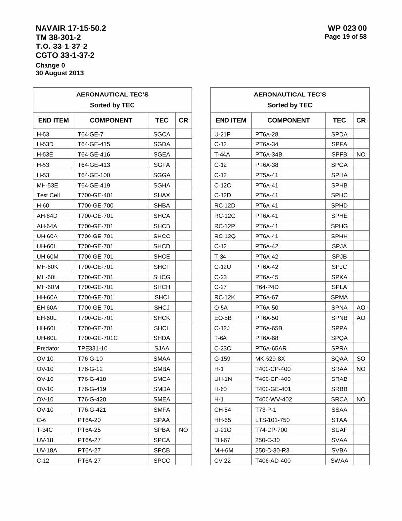
NAVAIR 17-15-50.2 TM 38-301-2 T.O. 33-1-37-2 CGTO 33-1-37-2
WP 023 00 Page 19 of 58
Change 0 30 August 2013
AERONAUTICAL TEC’S Sorted by TEC
END ITEM COMPONENT TEC CR
H-53 T64-GE-7 SGCA H-53D T64-GE-415 SGDA H-53E T64-GE-416 SGEA H-53 T64-GE-413 SGFA H-53 T64-GE-100 SGGA MH-53E T64-GE-419 SGHA Test Cell T700-GE-401 SHAX H-60 T700-GE-700 SHBA AH-64D T700-GE-701 SHCA AH-64A T700-GE-701 SHCB UH-60A T700-GE-701 SHCC UH-60L T700-GE-701 SHCD UH-60M T700-GE-701 SHCE MH-60K T700-GE-701 SHCF MH-60L T700-GE-701 SHCG MH-60M T700-GE-701 SHCH HH-60A T700-GE-701 SHCI EH-60A T700-GE-701 SHCJ EH-60L T700-GE-701 SHCK HH-60L T700-GE-701 SHCL UH-60L T700-GE-701C SHDA Predator TPE331-10 SJAA OV-10 T76-G-10 SMAA OV-10 T76-G-12 SMBA OV-10 T76-G-418 SMCA OV-10 T76-G-419 SMDA OV-10 T76-G-420 SMEA OV-10 T76-G-421 SMFA C-6 PT6A-20 SPAA T-34C PT6A-25 SPBA NO
UV-18 PT6A-27 SPCA UV-18A PT6A-27 SPCB C-12 PT6A-27 SPCC
AERONAUTICAL TEC’S Sorted by TEC
END ITEM COMPONENT TEC CR
U-21F PT6A-28 SPDA C-12 PT6A-34 SPFA T-44A PT6A-34B SPFB NO
C-12 PT6A-38 SPGA C-12 PT5A-41 SPHA C-12C PT6A-41 SPHB C-12D PT6A-41 SPHC RC-12D PT6A-41 SPHD RC-12G PT6A-41 SPHE RC-12P PT6A-41 SPHG RC-12Q PT6A-41 SPHH C-12 PT6A-42 SPJA T-34 PT6A-42 SPJB C-12U PT6A-42 SPJC C-23 PT6A-45 SPKA C-27 T64-P4D SPLA RC-12K PT6A-67 SPMA O-5A PT6A-50 SPNA AO
EO-5B PT6A-50 SPNB AO
C-12J PT6A-65B SPPA T-6A PT6A-68 SPQA C-23C PT6A-65AR SPRA G-159 MK-529-8X SQAA SO
H-1 T400-CP-400 SRAA NO
UH-1N T400-CP-400 SRAB H-60 T400-GE-401 SRBB H-1 T400-WV-402 SRCA NO
CH-54 T73-P-1 SSAA HH-65 LTS-101-750 STAA U-21G T74-CP-700 SUAF TH-67 250-C-30 SVAA MH-6M 250-C-30-R3 SVBA CV-22 T406-AD-400 SWAA

NAVAIR 17-15-50.2 TM 38-301-2 T.O. 33-1-37-2 CGTO 33-1-37-2
WP 023 00 Page 20 of 58
Change 0 30 August 2013
Table 3 – Non-Aeronautical Type Equipment Codes U.S. Marine Corps Components
Non-Aeronautical USMC TEC’s
EIMOD COMPMOD TEC
1150-MC A38714 MEDH 1150-MC DD453 MEGC 1150-MC HYD SYS MEDN 4000K-MC 18314-2 MJBG 4000K-MC 4BT3.9 MJBA 4000-MC DD353 MEBC 4000-MC HYD SYS MEBN 4000-MC TTB2221-1 MEBJ 420-C-MC DD353 MECB 420-C-MC HMD2315CB MECH 48MC-MC DD453 MEBB 48MC-MC HR18325 MEBH 580-MC A38714 MEFH 580-MC CASE-G188D MEFB 6000K-MC 6359T MKZA 6000K-MC FUNK-1724 MKZG 6000RTL-MC A3331-1 MDBJ 6000RLT-MC A38714 MDAG 6000RLT-MC DD453 MDBB 6000RLT-MC HYD SYS MDBN 6000RLT-MC MHR18325 MDAH UH-60L HYD SYS 3 HL32 600GPM-MC DD353 MEDC 621B-MC 3406 MECA 621B-MC 7G2780 MECG 621B-MC HYD SYS MECN 72-31-MC CRT 3333-1 MEEH 72-31-MC DD471 MEEC 72-31-MC HYD SYS MEEN AAVC7A1-MC HS400-3A1 MWAG AAVC7A1-MC VT-400 MWAA AAVP7A1-MC HS400-3A1 MWBG AAVP7A1-MC VT-400 MWBA AAVR7A1-MC HS400-3A1 MWCG AAVR7A1-MC HYD SYS NWCN AAVR7A1-MC VT-400 MWCA AIRCOMP-MC DEUTZ-F4L912 META AVLB-MC 1790-2DA MAGB AVLB-MC CD850-6A MAGH
Non-Aeronautical USMC TEC’s
EIMOD COMPMOD TEC
AVLB-MC HYD SYS MAJN BRIDGE-MC SABRE 212 MXJA CAT-130G-MC 5R6172 MEMH CAT-130G-MC CAT-3304 MEMC CAT-130G-MC HYD SYS MEMN CAT-D7G-MC 9R5382 MENG CAT-D7G-MC CAT-3306 MENA CAT-D7G-MC HYD SYS MENN CAUSEWAY-MC CMD-2A-221 MWFN CAUSEWAY-MC DD8V71T MWDC CAUSEWAY-MC F301HY1PCNTB MWQN CAUSEWAY-MC MH30L MWDH CAUSEWAY-MC PAVC38RA MWEN CAUSEWAY-MC RSA 04K MWDN COMPACTO-MC DD4534 MVPA COMPACTO-MC HMD2315CB MVPG CONMIXER-MC TRI-02 MEMB CRANE-MC 4133.9 MEKA CRANE-MC CAT-3208T MXBA CRANE-MC CLARK-28000 MXBG CRANE-MC FUNK-17243E MEKG DECONAPP-MC 4A084-3 MBQA DRCH2500-MC DD6V53 MEAB DRCH2500-MC R28621-12 MEAH EXCAVATO-MC 5043-7000 MEJA EXCAVATO-MC FUNK-17243E MEJG GRADER-MC CAT-3304 MEGA GRADER-MC POWESHIFT MEGG HOSEREEL-MC AT5CC MDCN HOSEREEL-MC DD371 MDCB LAV-25-MC DD6V53T MWGA LAV-25-MC MT653 MWGG LAV-AT-MC DD6V53T MWHA LAV-AT-MC MT653DR MWHG LAV-C2-MC DD6V53T MWJA LAV-C2-MC MT653DR MWJG LAV-L-MC DD6V53T MWKA LAV-L-MC MT653DR MWKG LAV-M-MC DD6V53T MWLA
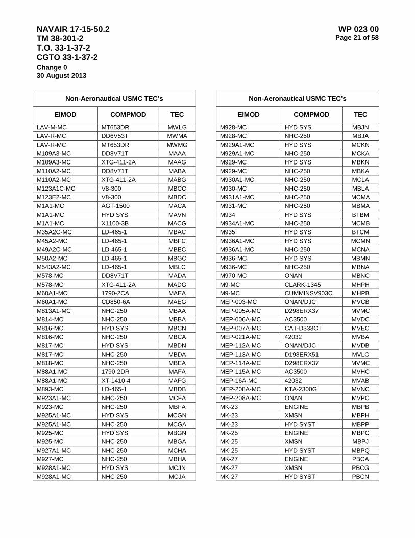
NAVAIR 17-15-50.2 TM 38-301-2 T.O. 33-1-37-2 CGTO 33-1-37-2
WP 023 00 Page 21 of 58
Change 0 30 August 2013
Non-Aeronautical USMC TEC’s
EIMOD COMPMOD TEC
LAV-M-MC MT653DR MWLG LAV-R-MC DD6V53T MWMA LAV-R-MC MT653DR MWMG M109A3-MC DD8V71T MAAA M109A3-MC XTG-411-2A MAAG M110A2-MC DD8V71T MABA M110A2-MC XTG-411-2A MABG M123A1C-MC V8-300 MBCC M123E2-MC V8-300 MBDC M1A1-MC AGT-1500 MACA M1A1-MC HYD SYS MAVN M1A1-MC X1100-3B MACG M35A2C-MC LD-465-1 MBAC M45A2-MC LD-465-1 MBFC M49A2C-MC LD-465-1 MBEC M50A2-MC LD-465-1 MBGC M543A2-MC LD-465-1 MBLC M578-MC DD8V71T MADA M578-MC XTG-411-2A MADG M60A1-MC 1790-2CA MAEA M60A1-MC CD850-6A MAEG M813A1-MC NHC-250 MBAA M814-MC NHC-250 MBBA M816-MC HYD SYS MBCN M816-MC NHC-250 MBCA M817-MC HYD SYS MBDN M817-MC NHC-250 MBDA M818-MC NHC-250 MBEA M88A1-MC 1790-2DR MAFA M88A1-MC XT-1410-4 MAFG M893-MC LD-465-1 MBDB M923A1-MC NHC-250 MCFA M923-MC NHC-250 MBFA M925A1-MC HYD SYS MCGN M925A1-MC NHC-250 MCGA M925-MC HYD SYS MBGN M925-MC NHC-250 MBGA M927A1-MC NHC-250 MCHA M927-MC NHC-250 MBHA M928A1-MC HYD SYS MCJN M928A1-MC NHC-250 MCJA
Non-Aeronautical USMC TEC’s
EIMOD COMPMOD TEC
M928-MC HYD SYS MBJN M928-MC NHC-250 MBJA M929A1-MC HYD SYS MCKN M929A1-MC NHC-250 MCKA M929-MC HYD SYS MBKN M929-MC NHC-250 MBKA M930A1-MC NHC-250 MCLA M930-MC NHC-250 MBLA M931A1-MC NHC-250 MCMA M931-MC NHC-250 MBMA M934 HYD SYS BTBM M934A1-MC NHC-250 MCMB M935 HYD SYS BTCM M936A1-MC HYD SYS MCMN M936A1-MC NHC-250 MCNA M936-MC HYD SYS MBMN M936-MC NHC-250 MBNA M970-MC ONAN MBNC M9-MC CLARK-1345 MHPH M9-MC CUMMINSV903C MHPB MEP-003-MC ONAN/DJC MVCB MEP-005A-MC D298ERX37 MVMC MEP-006A-MC AC3500 MVDC MEP-007A-MC CAT-D333CT MVEC MEP-021A-MC 42032 MVBA MEP-112A-MC ONAN/DJC MVDB MEP-113A-MC D198ERX51 MVLC MEP-114A-MC D298ERX37 MVMC MEP-115A-MC AC3500 MVHC MEP-16A-MC 42032 MVAB MEP-208A-MC KTA-2300G MVNC MEP-208A-MC ONAN MVPC MK-23 ENGINE MBPB MK-23 XMSN MBPH MK-23 HYD SYST MBPP MK-25 ENGINE MBPC MK-25 XMSN MBPJ MK-25 HYD SYST MBPQ MK-27 ENGINE PBCA MK-27 XMSN PBCG MK-27 HYD SYST PBCN

NAVAIR 17-15-50.2 TM 38-301-2 T.O. 33-1-37-2 CGTO 33-1-37-2
WP 023 00 Page 22 of 58
Change 0 30 August 2013
Non-Aeronautical USMC TEC’s
EIMOD COMPMOD TEC
MK-28 ENGINE PBDA MK-28 XMSN PBDG MK-28 HYD SYST PBDN MK48 4X4-MC DD8V92TA MBPA MK48 4X4-MC HT740D MBPG MK48 4X4-MC HYD SYS MBPN P19A-MC ALLIS750DRD MBRH P19A-MC NHC-250 MBRB P250WDN-MC F2L511 MEMA RTCH-MC 3P9094 MDAW RTCH-MC CAT-3408T MDAC RTCH-MC CAT-5R3855 MDAJ RTCH-MC HYD SYS MDAN SCRAPER-MC 3406 MEHA SCRAPER-MC POWERSHIFT MEHG SLWT-4-MC 70823300 MAEB SLWT-4-MC CMD-2A-221 MAGN SLWT-4-MC DD8V71T MAEC SLWT-4-MC F301HY1PCNTB MAHN SLWT-4-MC MH30L MAEH SLWT-4-MC PAVC38RA MAFN SLWT-4-MC RSA 04K MAEN SWEEPER-MC 4239D MSEA SWEEPER-MC ALLISON-540 MSEG TRACTOR-MC 4WG-200 MJCG TRACTOR-MC 6076ADW02 MJCA TRACTOR-MC BENZ-320 MEDA TRACTOR-MC BENZ-MECH MEDG TRACTOR-MC CASE-6T590 MHPA TRACTOR-MC CASE-G107561 MHPG TRK FIRE-MC NTC-400 MTCA CSTRS WNCH GEARBOX DLCA WINCH-MC 1489 MDDN WINCH-MC 50438301 MDDB WINCH-MC DD453 MDDC WLDTLMTD-MC PERKINS4236 MEFC

NAVAIR 17-15-50.2 TM 38-301-2 T.O. 33-1-37-2 CGTO 33-1-37-2
WP 023 00 Page 23 of 58
Change 0 30 August 2013
Table 4 – Non-Aeronautical Type Equipment Codes Army Components
Non-Aeronautical Army TEC’s
EIMOD COMPMOD TEC
10000M 6BT5.9 DJFA 10000M FUNK-1723M DJFG 10000M HYD SYS DJFN 1200 CSG649 NC4A 1200 C-6 NC4G 1500M DD6V53 TVAA 140H CAT-3306 EHAB 140H CAT-1442234 EHAG 140H HYD SYS EHAM 175B CLK4000 EFBG 175B DD8V71N EFBF 175B HYD SYS EFBN 175B NT-855-C EFBB 1854 9.0L180F NB2A 1854 CM-5552D NB2G 1854 HYD SYS NB2N 2500L DD6V92 TCWA 2500L HT750DRD TCWG 250DCMS1 JD403 DWSA 250RPV DD453 DWLA 270-9 DD353 EU5A 3000 KW-N CB LSV16T PVDA 3000M 2067761 DJ8G 3000M C-180 DJ8A 35KVA GPT 30-150E TVYA 4200 3TNE78A NB5A 4200 4200HST NB5G 4200 HYD SYS NB5M 444C 6329 NA5A 444C NOII NA5G 444C HYD SYS NA5M 450D 4219 NA7A 450D NOII NA7G 450D HYD SYS NA7M 450E TO4276 NC3A 450E JD4SPD NC3G 450E HYD SYS NC3M 4700 T444E NA4A 4700 AT545 NA4G 4700 HYD SYS NA4M
Non-Aeronautical Army TEC’s
EIMOD COMPMOD TEC
4800 DT466 NB9A 4800 MT643 NB9G 4800 HYD SYS NB9M 5060 DD23010052 EMKG 5060 DD471T EMKA 515 D-359N NC2A 515 S710 NC2G 515 HYD SYS NC2M 530B LDS-465-1 TEDA 530BAM LDS-465-1 TEEA 544E HYD SYS TDBN 544E JD6059TDW04 TDBA 544E WG-120 TDBG 609-C F6L912B ZTCA 6000M 6BT5.9 TDHA 6000M FUNK-1723 TDHG 6000M HYD SYS TDHN 600TV75 T-1010 S-39 TVFA 613BSNS 8S3543 EHZG 613BSNS CAT-3208 EHZA 613BSNS HYD SYS EHZN 613BSNSI 8S3543 EJLG 613BSNSI CAT-3208 EJLA 613BSNSI HYD SYS EJLN 613BSS 8S3543 EH2G 613BSS CAT-3208 EH2A 613BSS HYD SYS EH2N 613BSSI 8S3543 EJKG 613BSSI CAT-3208 EJKA 613BSSI HYD SYS EJKN 613BWDNS 8S3543 EVGG 613BWDNS CAT-3208 EVGA 613BWDNS HYD SYS EVGN 613BWDS 8S3543 EVFG 613BWDS CAT-3208 EVFA 613BWDS HYD SYS EVFN 621B 3406 EH3A 621B 7G2780 EH3G 621B HYD SYS EH3N 645M AC3500 EFLA

NAVAIR 17-15-50.2 TM 38-301-2 T.O. 33-1-37-2 CGTO 33-1-37-2
WP 023 00 Page 24 of 58
Change 0 30 August 2013
Non-Aeronautical Army TEC’s
EIMOD COMPMOD TEC
645M HYD SYS EFLN 645M TT2420-1 EFLG 6M125 D2000X16 TVGA 750PQ DD6V71N TVJA 75TPH EAGLE N855-P235 TFAA 780T T4.236 E47A 950BNS 7G4851 EFWG 950BNS CAT-3304 EGEA 950BNS HYD SYS EFWN 950BNSCE 7G4851 EGEG 950BNSCE CAT-3304 EGEA 950BMSCE HYD SYS EGEN 950BS 7G4851 EFVG 950BS CAT-3304 EFVA 950BS HYD SYS EFVN 950BSCE 7G4851 EGFG 950BSCE CAT-3304 EGFA 950BSCE HYD SYS EGFN AMTC HYD SYS TMTN AN/MJQ-10A D298ERX37 VCOA AN/MJQ-11A CAT-D343TA VENA AN/MJQ-12A AC3500 VELA AN/MJQ-15 D198ERX51 VLOA AN/MJQ-18 D198ERX51 VLAA AN/MJQ-18 100-1345 VLAB AN/MJQ-21 T62T32A VIHA AN/MJQ-24 A04043B02 VICA AN/MJQ-35 DN2M VICD AN/MJQ-35A DN2M VICE AN/MJQ-36 DN2M VICF AN/MJQ-37 DN4M-1 VIDA AN/MJQ-38 DN4M-1 VIDB AN/MJQ-39 ISUZU-C240 VICJ AN/MJQ-40 JD4039T VICB AN/MJQ-41 JD6059T VICC AP308 4B3.96 DXLA AP308 FORD C-6 DXLG APP-1 GTCP85-127 VAFC ARTFT6 ALS 3331-1 DJCG ARTFT6 DD453N DJCF ARTFT6 HYD SYS DJCN
Non-Aeronautical Army TEC’s
EIMOD COMPMOD TEC
AT422T 13.9LFHR ELTG AT422T 6BTA5.9 ELTA AT422T HYD SYS ELTM B413 RTG3600C-S1 TVPB B8 4-53T NA9A B8 13.3HR28420 NA9G B8 HYD SYS NA9M BBBUESCSBMK1 10-18-002 XJGG BBBUESCSBMK1 SABRE 212 XJGA BBBUESCSBMK2 10-18-002 TWVG BBBUESCSBMK2 SAVE 212 TWVA BD 264B CO-5EN668 WACE BD 264B CO-6EN68 WACB BD 264B CO-DSM-6 WACC BD 264B CO-GAB4 WACA BD 264B FM-316A6 WACD BD-6802 NTA-855-63 WB1A BD-6802 KTA38-G2 WB1B BD-6802 HYD SYS WB1M BD-6802 HYD SYS ANC1 WB1N BD-6802 HYD SYS ANC2 WB2N BD-6802 HYD SYS ANC3 WB3N BIO-RAD FT-IR GRDA BP 4002 WAHA BP 4003 WAFA BRIDGE-MA DD8V71 TWDA BRIDGE-MA HT70 TWDG BSF-400 DD353 EXEA BSF-400 HYD SYS EXEN C350B DD353 TEHA C350B HYD SYS TEHN C350B-D DD353 TEWA C3508-D HYD SYS TEWN C530A 393303 EURG C530A DD353 EURA CAT-12 CAT-D333 EHKA CAT-120ROPS 3R9859 EHKG CAT-130G 5R6192 EHFG CAT-130G CAT-330DIT EHFA CAT-130G HYD SYS EHFN CAT-130GNS CAT-3304 EHNA

NAVAIR 17-15-50.2 TM 38-301-2 T.O. 33-1-37-2 CGTO 33-1-37-2
WP 023 00 Page 25 of 58
Change 0 30 August 2013
Non-Aeronautical Army TEC’s
EIMOD COMPMOD TEC
CAT-130GNS 5R6192 EHNG CAT-130GNS HYD SYS EHNN CAT-130GNSC 5R6192 EJJG CAT-130GNSC CAT-3304DIT EJJA CAT-130GNSC HYD SYS EJJN CAT-130GNSE 5R6192 TAAG CAT-130GNSE CAT-3304 TAAA CAT-130GNSE HYD SYS TAAN CAT-130GS 5R6192 EHPG CAT-130GS CAT-3304 EHPA CAT-130GS HYD SYS EHPN CAT-130GSCE 5R6192 TABG CAT-130GSCE CAT-3304 TABA CAT-130GSCE HYD SYS TABN CAT-814F 1223774 E5DG CAT-814F CAT-3306B E5DA CAT-814F HYD SYS E5DM CAT-815F 1223774 E5EG CAT-815F CAT-3306B E5EA CAT-815F HYD SYS E5EM CAT-816F 1223774 E5FG CAT-816F CAT-3306B E5FA CAT-816F HYD SYS E5FM CAT-D5 3S7094 EAPG CAT-D5 CAT-3306 E5FA CAT-D5 HYD SYS E5FM CAT-D5A 3S7094 EAPG CAT-D5A CAT-3306 EAPA CAT-D5A HYD SYS EANN CAT-D5B 3S7094 TEKG CAT-D5B 9P4905 TEKH CAT-D5B CAT-2WA1/UP TEKI CAT-D5B CAT-3306 TEKA CAT-D5B D5/3T3394 TEKJ CAT-D5B HYD SYS TEKN CAT-D7E CAT-D333 EA3G CAT-D7F 5R82 EA2G CAT-D7F CAT-3306 EA2A CAT-D7F CAT-6CYL638C EA2B CAT-D7F HYD SYS EA2N CAT-D7G 9P5382 TELG
Non-Aeronautical Army TEC’s
EIMOD COMPMOD TEC
CAT-D7G CAT-3306 TELA CAT-D7G HYD SYS TELN CAT-D7H 9P5382 TELH CAT-D7H CAT-3306 TELB CAT-D7H HYD SYS TELM CAT-D7R CAT-3306 TEMA CAT-D7R CAT-9TXI-UP TEMG CAT-D7R HYD SYS TEMN CAT-D8K 3N1869 EADG CAT-D8K CAT-D342 EADA CAT-D8K HYD SYS EADN CB-534B CAT-3054 E5BA CB-534B HYD SYS E5BN CS433C HYD SYS E5HM CS433C CAT-3054 E5KA CS563D CAT-3114 E5JA CS563D CAT-3116 E5JB CS563D CAT-3126 E5JC CS563D HYD SYS E5JM D424A A0403B02 TVPA D5 HYD SYS EAPM D5 ENG TS HYD SYS TB3N D5BNS CAT-2WA1/UP EBAH D5BNS CAT-3306 EBAA D5BNS D5/3T3394 EBAG D5BS CAT-2WA1/UP EBBH D5BS CAT-3306 EBBA D5BS D5/3T3394 EBBG D5BS HYD SYS EBBN D5BS1 CAT-2WA1/UP TFBA D5BS1 CAT-3306 TFBG D5BS1 D5/3394 TFBH D5BS1 HYD SYS TFBN D6 HYD SYS TCMM DV43 CAT-2408T DJNA DV43 CAT-3408 DJNB DV43 CAT-3P9094 DJNH DV43 CAT-5R3855 DJNG DV43 HYD SYS DJNN DV-100 HYD SYS EBCM DV-100 POWER SHIFT JCCG
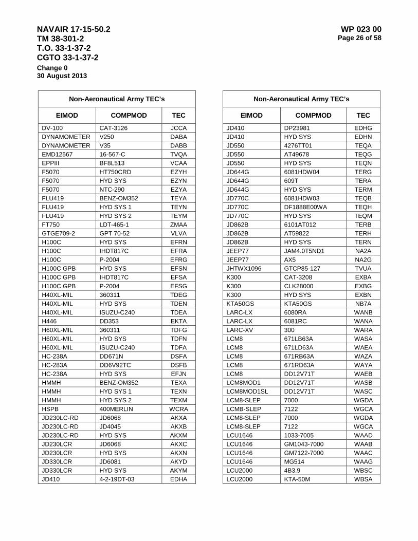
NAVAIR 17-15-50.2 TM 38-301-2 T.O. 33-1-37-2 CGTO 33-1-37-2
WP 023 00 Page 26 of 58
Change 0 30 August 2013
Non-Aeronautical Army TEC’s
EIMOD COMPMOD TEC
DV-100 CAT-3126 JCCA DYNAMOMETER V250 DABA DYNAMOMETER V35 DABB EMD12567 16-567-C TVQA EPPIII BF8L513 VCAA F5070 HT750CRD EZYH F5070 HYD SYS EZYN F5070 NTC-290 EZYA FLU419 BENZ-OM352 TEYA FLU419 HYD SYS 1 TEYN FLU419 HYD SYS 2 TEYM FT750 LDT-465-1 ZMAA GTGE709-2 GPT 70-52 VLVA H100C HYD SYS EFRN H100C IHDT817C EFRA H100C P-2004 EFRG H100C GPB HYD SYS EFSN H100C GPB IHDT817C EFSA H100C GPB P-2004 EFSG H40XL-MIL 360311 TDEG H40XL-MIL HYD SYS TDEN H40XL-MIL ISUZU-C240 TDEA H446 DD353 EKTA H60XL-MIL 360311 TDFG H60XL-MIL HYD SYS TDFN H60XL-MIL ISUZU-C240 TDFA HC-238A DD671N DSFA HC-283A DD6V92TC DSFB HC-238A HYD SYS EFJN HMMH BENZ-OM352 TEXA HMMH HYD SYS 1 TEXN HMMH HYD SYS 2 TEXM HSPB 400MERLIN WCRA JD230LC-RD JD6068 AKXA JD230LC-RD JD4045 AKXB JD230LC-RD HYD SYS AKXM JD230LCR JD6068 AKXC JD230LCR HYD SYS AKXN JD330LCR JD6081 AKYD JD330LCR HYD SYS AKYM JD410 4-2-19DT-03 EDHA
Non-Aeronautical Army TEC’s
EIMOD COMPMOD TEC
JD410 DP23981 EDHG JD410 HYD SYS EDHN JD550 4276TT01 TEQA JD550 AT49678 TEQG JD550 HYD SYS TEQN JD644G 6081HDW04 TERG JD644G 609T TERA JD644G HYD SYS TERM JD770C 6081HDW03 TEQB JD770C DF1888E00WA TEQH JD770C HYD SYS TEQM JD862B 6101AT012 TERB JD862B AT59822 TERH JD862B HYD SYS TERN JEEP77 JAM4.0T5ND1 NA2A JEEP77 AX5 NA2G JHTWX1096 GTCP85-127 TVUA K300 CAT-3208 EXBA K300 CLK28000 EXBG K300 HYD SYS EXBN KTA50GS KTA50GS NB7A LARC-LX 6080RA WANB LARC-LX 6081RC WANA LARC-XV 300 WARA LCM8 671LB63A WASA LCM8 671LD63A WAEA LCM8 671RB63A WAZA LCM8 671RD63A WAYA LCM8 DD12V71T WAEB LCM8MOD1 DD12V71T WASB LCM8MOD1SL DD12V71T WASC LCM8-SLEP 7000 WGDA LCMB-SLEP 7122 WGCA LCM8-SLEP 7000 WGDA LCM8-SLEP 7122 WGCA LCU1646 1033-7005 WAAD LCU1646 GM1043-7000 WAAB LCU1646 GM7122-7000 WAAC LCU1646 MG514 WAAG LCU2000 4B3.9 WBSC LCU2000 KTA-50M WBSA
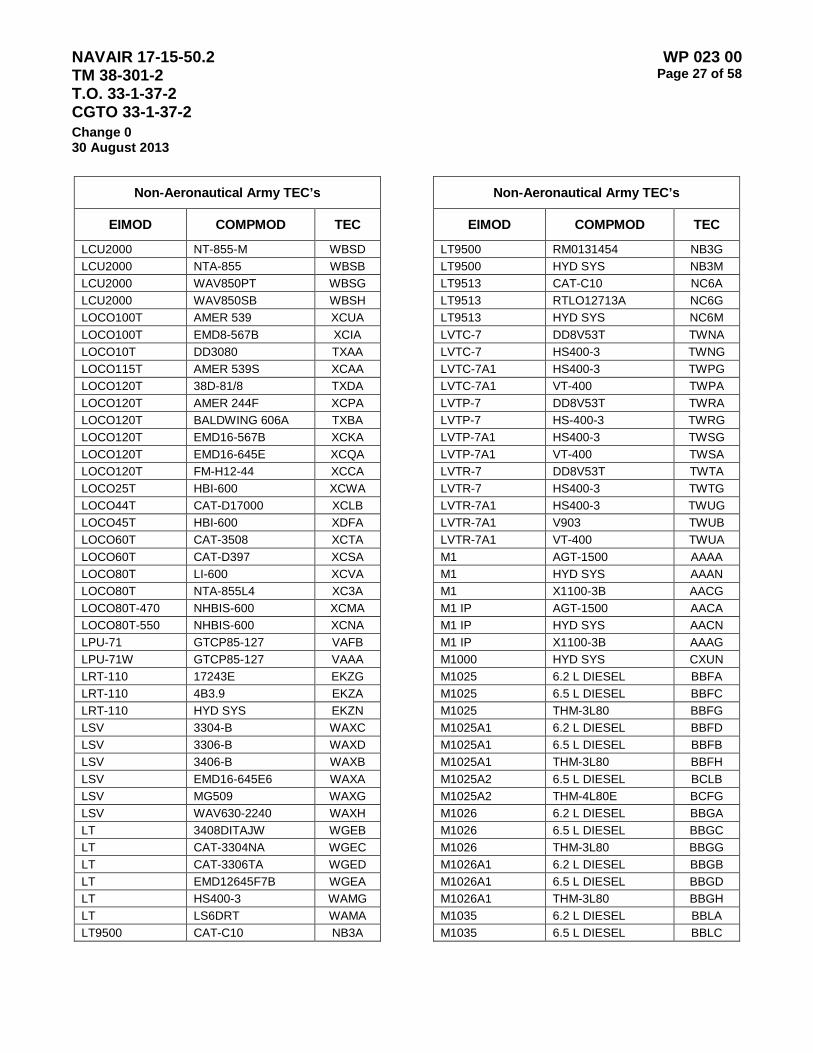
NAVAIR 17-15-50.2 TM 38-301-2 T.O. 33-1-37-2 CGTO 33-1-37-2
WP 023 00 Page 27 of 58
Change 0 30 August 2013
Non-Aeronautical Army TEC’s
EIMOD COMPMOD TEC
LCU2000 NT-855-M WBSD LCU2000 NTA-855 WBSB LCU2000 WAV850PT WBSG LCU2000 WAV850SB WBSH LOCO100T AMER 539 XCUA LOCO100T EMD8-567B XCIA LOCO10T DD3080 TXAA LOCO115T AMER 539S XCAA LOCO120T 38D-81/8 TXDA LOCO120T AMER 244F XCPA LOCO120T BALDWING 606A TXBA LOCO120T EMD16-567B XCKA LOCO120T EMD16-645E XCQA LOCO120T FM-H12-44 XCCA LOCO25T HBI-600 XCWA LOCO44T CAT-D17000 XCLB LOCO45T HBI-600 XDFA LOCO60T CAT-3508 XCTA LOCO60T CAT-D397 XCSA LOCO80T LI-600 XCVA LOCO80T NTA-855L4 XC3A LOCO80T-470 NHBIS-600 XCMA LOCO80T-550 NHBIS-600 XCNA LPU-71 GTCP85-127 VAFB LPU-71W GTCP85-127 VAAA LRT-110 17243E EKZG LRT-110 4B3.9 EKZA LRT-110 HYD SYS EKZN LSV 3304-B WAXC LSV 3306-B WAXD LSV 3406-B WAXB LSV EMD16-645E6 WAXA LSV MG509 WAXG LSV WAV630-2240 WAXH LT 3408DITAJW WGEB LT CAT-3304NA WGEC LT CAT-3306TA WGED LT EMD12645F7B WGEA LT HS400-3 WAMG LT LS6DRT WAMA LT9500 CAT-C10 NB3A
Non-Aeronautical Army TEC’s
EIMOD COMPMOD TEC
LT9500 RM0131454 NB3G LT9500 HYD SYS NB3M LT9513 CAT-C10 NC6A LT9513 RTLO12713A NC6G LT9513 HYD SYS NC6M LVTC-7 DD8V53T TWNA LVTC-7 HS400-3 TWNG LVTC-7A1 HS400-3 TWPG LVTC-7A1 VT-400 TWPA LVTP-7 DD8V53T TWRA LVTP-7 HS-400-3 TWRG LVTP-7A1 HS400-3 TWSG LVTP-7A1 VT-400 TWSA LVTR-7 DD8V53T TWTA LVTR-7 HS400-3 TWTG LVTR-7A1 HS400-3 TWUG LVTR-7A1 V903 TWUB LVTR-7A1 VT-400 TWUA M1 AGT-1500 AAAA M1 HYD SYS AAAN M1 X1100-3B AACG M1 IP AGT-1500 AACA M1 IP HYD SYS AACN M1 IP X1100-3B AAAG M1000 HYD SYS CXUN M1025 6.2 L DIESEL BBFA M1025 6.5 L DIESEL BBFC M1025 THM-3L80 BBFG M1025A1 6.2 L DIESEL BBFD M1025A1 6.5 L DIESEL BBFB M1025A1 THM-3L80 BBFH M1025A2 6.5 L DIESEL BCLB M1025A2 THM-4L80E BCFG M1026 6.2 L DIESEL BBGA M1026 6.5 L DIESEL BBGC M1026 THM-3L80 BBGG M1026A1 6.2 L DIESEL BBGB M1026A1 6.5 L DIESEL BBGD M1026A1 THM-3L80 BBGH M1035 6.2 L DIESEL BBLA M1035 6.5 L DIESEL BBLC
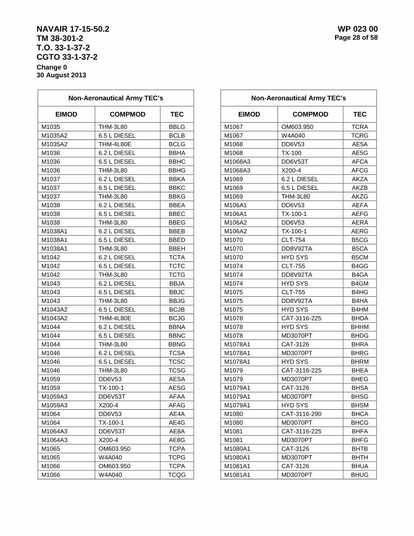
NAVAIR 17-15-50.2 TM 38-301-2 T.O. 33-1-37-2 CGTO 33-1-37-2
WP 023 00 Page 28 of 58
Change 0 30 August 2013
Non-Aeronautical Army TEC’s
EIMOD COMPMOD TEC
M1035 THM-3L80 BBLG M1035A2 6.5 L DIESEL BCLB M1035A2 THM-4L80E BCLG M1036 6.2 L DIESEL BBHA M1036 6.5 L DIESEL BBHC M1036 THM-3L80 BBHG M1037 6.2 L DIESEL BBKA M1037 6.5 L DIESEL BBKC M1037 THM-3L80 BBKG M1038 6.2 L DIESEL BBEA M1038 6.5 L DIESEL BBEC M1038 THM-3L80 BBEG M1038A1 6.2 L DIESEL BBEB M1038A1 6.5 L DIESEL BBED M1038A1 THM-3L80 BBEH M1042 6.2 L DIESEL TCTA M1042 6.5 L DIESEL TCTC M1042 THM-3L80 TCTG M1043 6.2 L DIESEL BBJA M1043 6.5 L DIESEL BBJC M1043 THM-3L80 BBJG M1043A2 6.5 L DIESEL BCJB M1043A2 THM-4L80E BCJG M1044 6.2 L DIESEL BBNA M1044 6.5 L DIESEL BBNC M1044 THM-3L80 BBNG M1046 6.2 L DIESEL TCSA M1046 6.5 L DIESEL TCSC M1046 THM-3L80 TCSG M1059 DD6V53 AESA M1059 TX-100-1 AESG M1059A3 DD6V53T AFAA M1059A3 X200-4 AFAG M1064 DD6V53 AE4A M1064 TX-100-1 AE4G M1064A3 DD6V53T AE8A M1064A3 X200-4 AE8G M1065 OM603.950 TCPA M1065 W4A040 TCPG M1066 OM603.950 TCPA M1066 W4A040 TCQG
Non-Aeronautical Army TEC’s
EIMOD COMPMOD TEC
M1067 OM603.950 TCRA M1067 W4A040 TCRG M1068 DD6V53 AE5A M1068 TX-100 AE5G M1068A3 DD6V53T AFCA M1068A3 X200-4 AFCG M1069 6.2 L DIESEL AKZA M1069 6.5 L DIESEL AKZB M1069 THM-3L80 AKZG M106A1 DD6V53 AEFA M106A1 TX-100-1 AEFG M106A2 DD6V53 AERA M106A2 TX-100-1 AERG M1070 CLT-754 B5CG M1070 DD8V92TA B5CA M1070 HYD SYS B5CM M1074 CLT-755 B4GG M1074 DD8V92TA B4GA M1074 HYD SYS B4GM M1075 CLT-755 B4HG M1075 DD8V92TA B4HA M1075 HYD SYS B4HM M1078 CAT-3116-225 BHDA M1078 HYD SYS BHHM M1078 MD3070PT BHDG M1078A1 CAT-3126 BHRA M1078A1 MD3070PT BHRG M1078A1 HYD SYS BHRM M1079 CAT-3116-225 BHEA M1079 MD3070PT BHEG M1079A1 CAT-3126 BHSA M1079A1 MD3070PT BHSG M1079A1 HYD SYS BHSM M1080 CAT-3116-290 BHCA M1080 MD3070PT BHCG M1081 CAT-3116-225 BHFA M1081 MD3070PT BHFG M1080A1 CAT-3126 BHTB M1080A1 MD3070PT BHTH M1081A1 CAT-3126 BHUA M1081A1 MD3070PT BHUG

NAVAIR 17-15-50.2 TM 38-301-2 T.O. 33-1-37-2 CGTO 33-1-37-2
WP 023 00 Page 29 of 58
Change 0 30 August 2013
Non-Aeronautical Army TEC’s
EIMOD COMPMOD TEC
M1081A1 HYD SYS BHUM M1083 CAT-3116-290 BR2A M1083 MD3070PT BR2G M1083A1 CAT-3126 BT9A M1083A1 MD3070PT BT9G M1083A1 HYD SYS BT9M M1084 CAT-3116-290 BR3A M1084 HYD SYS BR3N M1084 MD3070PT BR3G M1084A1 CAT-3126 BUBA M1084A1 MD3070PT BUBG M1084A1 HYD SYS BUBM M1085 CAT-3116-290 BR7A M1085 MD3070PT BR7G M1085A1 CAT-3126 BUGA M1085A1 MD3070PT BUGG M1085A1 HYD SYS BUGM M1086 CAT-3116-290 BR8A M1086 HYD SYS BR8N M1086 MD3070PT BR8G M1086A1 CAT-3126 BUHA M1086A1 MD3070PT BUHG M1086A1 HYD SYS BUHM M1087 CAT-3116-290 BT3A M1087 MD3070PT BT3G M1087A1 CAT-3126 BUTA M1087A1 MD3070PT BUTG M1088 CAT-3116-290 BTJA M1088 MD3070PT BTJG M1088A1 CAT-3126 BUCA M1088A1 MD3070PT BUCG M1088A1 HYD SYS BUCM M1089 CAT-3116-290 BR4A M1089 HYD SYS BR4N M1089 MD3070PT BR4G M1089A1 CAT-3126 BUDA M1089A1 MD3070PT BUDG M1089A1 HYD SYS BUDM M1090 CAT-3116-290 BR5A M1090 HYD SYS BR5N M1090 MD3070PT BR5G
Non-Aeronautical Army TEC’s
EIMOD COMPMOD TEC
M1090A1 CAT-3126 BUEA M1090A1 MD3070PT BUEG M1090A1 HYD SYS BUEM M1091 CAT-3116-290 BT2A M1091 MD3070PT BT2G M1091A1 CAT-3126 BUSA M1091A1 MD3070PT BUSG M1092 CAT-3116-290 BRZA M1092 MD3070PT BRZG M1092A1 CAT-3126 BT8A M1092A1 MD3070PT BT8G M1093 CAT-3116-290 BR9A M1093 MD3070PT BR9G M1093A1 CAT-3126 BUAA M1093A1 MD3070PT BUAG M1093A1 HYD SYS BUAM M1094 CAT-3116-290 BTKA M1094 HYD SYS BTKN M1094 MD3070PT BTKG M1094A1 CAT-3126 BUFA M1094A1 MD3070PT BUFG M1094A1 HYD SYS BUFM M1096 CAT-3116-290 BR6A M1096 HYD SYS BR6N M1096 MD3070PT BR6G M1097 6.2 L DIESEL BBMA M1097 THM-3L80 BBMG M1097 6.5 L DIESEL BBMC M1097A1 6.2 L DIESEL BBUA M1097A1 THM-3L80 BBUG M1097A2 6.5 L DIESEL BCMB M1097A2 THM-4L80E BCMG M109A3 LDT-465-1C BMJC M10A HYD SYS DJUN M10A IHCDT-466B DJUA M10A IHCS-700 DJUG M1109 6.2 L DIESEL B6AA M1109 THM-3L80 B6AG M1109 6.5 L DIESEL B6AC M1113 6.5 L DIESEL B6BA M1113 THM-4L80E B6BG
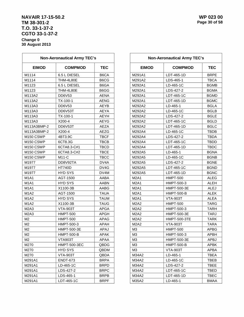
NAVAIR 17-15-50.2 TM 38-301-2 T.O. 33-1-37-2 CGTO 33-1-37-2
WP 023 00 Page 30 of 58
Change 0 30 August 2013
Non-Aeronautical Army TEC’s
EIMOD COMPMOD TEC
M1114 6.5 L DIESEL B6CA M1114 THM-4L80E B6CG M1123 6.5 L DIESEL B6GA M1123 THM-4L80E B6GG M113A2 DD6V53 AENA M113A2 TX-100-1 AENG M113A3 DD6V53 AEYB M113A3 DD6V53T AEYA M113A3 TX-100-1 AEYH M113A3 X200-4 AEYG M113A3BMP-2 DD6V53T AEZA M113A3BMP-2 X200-4 AEZG M150 CSWP 4BT3.9C TBCF M150 CSWP 6CT8.3G TBCB M150 CSWP 6CTA8.3-C#1 TBCD M150 CSWP 6CTA8.3-C#2 TBCE M150 CSWP M11-C TBCC M1977 DD8V92TA DV4A M1977 HT740D DV4G M1977 HYD SYS DV4M M1A1 AGT-1500 AABA M1A1 HYD SYS AABN M1A1 X1100-3B AABG M1A2 AGT-1500 TAUA M1A2 HYD SYS TAUM M1A2 X1100-3B TAUG M2A3 VTA-903T APGA M2A3 HMPT-500 APGH M2 HMPT-500 APAG M2 HMPT-500-3 APAH M2 HMPT-500-3E APAJ M2 HMPT-500-B APAK M2 VTA903T APAA M270 HMPT-500-3EC QBDG M270 HYD SYS QBDM M270 VTA-903T QBDA M291A1 ENDT-673 BRPA M291A1 LD-465-1C BRPD M291A1 LDS-427-2 BRPC M291A1 LDS-465-1 BRPB M291A1 LDT-465-1C BRPF
Non-Aeronautical Army TEC’s
EIMOD COMPMOD TEC
M291A1 LDT-465-1D BRPE M291A2 LDS-465-1 TBCA M292A1 LD-465-1C BGMB M292A1 LDS-427-2 BGMA M292A1 LDT-465-1C BGMD M292A1 LDT-465-1D BGMC M292A2 LD-465-1 BGLA M292A2 LD-465-1C BGLB M292A2 LDS-427-2 BGLE M292A2 LDT-465-1C BGLD M292A2 LDT-465-1D BGLC M292A4 LD-465-1C TBDB M292A4 LDS-427-2 TBDA M292A4 LDT-465-1C TBDD M292A4 LDT-465-1D TBDC M292A5 LD-465-1 BGNA M292A5 LD-465-1C BGNB M292A5 LDS-427-2 BGNE M292A5 LDT-465-1C BGND M292A5 LDT-465-1D BGNC M2A1 HMPT-500 ALEG M2A1 HMPT-500-3 ALEH M2A1 HMPT-500-3E ALEJ M2A1 HMPT-500-B ALEK M2A1 VTA-903T ALEA M2A2 HMPT-500 TARG M2A2 HMPT-500-3 TARH M2A2 HMPT-500-3E TARJ M2A2 HMPT-500-3TE TARK M2A2 VTA-903T TARA M3 HMPT-500 APBG M3 HMPT-500-3 APBH M3 HMPT-500-3E APBJ M3 HMPT-500-B APBK M3 VTA-903T APBA M34A2 LD-465-1 TBEA M34A2 LD-465-1C TBEB M34A2 LDS-427-2 TBEE M34A2 LDT-465-1C TBED M34A2 LDT-465-1D TBEC M35A2 LD-465-1 BMAA
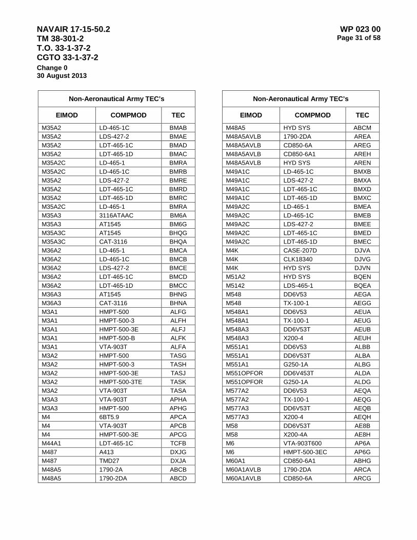
NAVAIR 17-15-50.2 TM 38-301-2 T.O. 33-1-37-2 CGTO 33-1-37-2
WP 023 00 Page 31 of 58
Change 0 30 August 2013
Non-Aeronautical Army TEC’s
EIMOD COMPMOD TEC
M35A2 LD-465-1C BMAB M35A2 LDS-427-2 BMAE M35A2 LDT-465-1C BMAD M35A2 LDT-465-1D BMAC M35A2C LD-465-1 BMRA M35A2C LD-465-1C BMRB M35A2 LDS-427-2 BMRE M35A2 LDT-465-1C BMRD M35A2 LDT-465-1D BMRC M35A2C LD-465-1 BMRA M35A3 3116ATAAC BM6A M35A3 AT1545 BM6G M35A3C AT1545 BHQG M35A3C CAT-3116 BHQA M36A2 LD-465-1 BMCA M36A2 LD-465-1C BMCB M36A2 LDS-427-2 BMCE M36A2 LDT-465-1C BMCD M36A2 LDT-465-1D BMCC M36A3 AT1545 BHNG M36A3 CAT-3116 BHNA M3A1 HMPT-500 ALFG M3A1 HMPT-500-3 ALFH M3A1 HMPT-500-3E ALFJ M3A1 HMPT-500-B ALFK M3A1 VTA-903T ALFA M3A2 HMPT-500 TASG M3A2 HMPT-500-3 TASH M3A2 HMPT-500-3E TASJ M3A2 HMPT-500-3TE TASK M3A2 VTA-903T TASA M3A3 VTA-903T APHA M3A3 HMPT-500 APHG M4 6BT5.9 APCA M4 VTA-903T APCB M4 HMPT-500-3E APCG M44A1 LDT-465-1C TCFB M487 A413 DXJG M487 TMD27 DXJA M48A5 1790-2A ABCB M48A5 1790-2DA ABCD
Non-Aeronautical Army TEC’s
EIMOD COMPMOD TEC
M48A5 HYD SYS ABCM M48A5AVLB 1790-2DA AREA M48A5AVLB CD850-6A AREG M48A5AVLB CD850-6A1 AREH M48A5AVLB HYD SYS AREN M49A1C LD-465-1C BMXB M49A1C LDS-427-2 BMXA M49A1C LDT-465-1C BMXD M49A1C LDT-465-1D BMXC M49A2C LD-465-1 BMEA M49A2C LD-465-1C BMEB M49A2C LDS-427-2 BMEE M49A2C LDT-465-1C BMED M49A2C LDT-465-1D BMEC M4K CASE-207D DJVA M4K CLK18340 DJVG M4K HYD SYS DJVN M51A2 HYD SYS BQEN M5142 LDS-465-1 BQEA M548 DD6V53 AEGA M548 TX-100-1 AEGG M548A1 DD6V53 AEUA M548A1 TX-100-1 AEUG M548A3 DD6V53T AEUB M548A3 X200-4 AEUH M551A1 DD6V53 ALBB M551A1 DD6V53T ALBA M551A1 G250-1A ALBG M551OPFOR DD6V453T ALDA M551OPFOR G250-1A ALDG M577A2 DD6V53 AEQA M577A2 TX-100-1 AEQG M577A3 DD6V53T AEQB M577A3 X200-4 AEQH M58 DD6V53T AE8B M58 X200-4A AE8H M6 VTA-903T600 AP6A M6 HMPT-500-3EC AP6G M60A1 CD850-6A1 ABHG M60A1AVLB 1790-2DA ARCA M60A1AVLB CD850-6A ARCG

NAVAIR 17-15-50.2 TM 38-301-2 T.O. 33-1-37-2 CGTO 33-1-37-2
WP 023 00 Page 32 of 58
Change 0 30 August 2013
Non-Aeronautical Army TEC’s
EIMOD COMPMOD TEC
M60A1AVLB CD850-6A1 ARCH M60A1AVLB HYD SYS ARCN M60A3 1790-2C ABBA M60A3 CD850-6A ABBG M60A3 CD850-6A1 ABBH M60A3 HYD SYS ABBN M7 VTA-903T AP7A M7 HMPT-500-3EC AP7G M764 LD-465-1 BMVA M792 DD353 BFAA M809 NHC-250 TBNA M809A1 NHC-250 TBPA M810 NHC-250 TBQA M811 NHC-250 BRNA M811A1 NHC-250 TBRA M811A2 NHC-250 TBSA M812 NHC-250 TBTA M812A1 NHC-250 TBUA M813 NHC-250 BSBA M813A1 NHC-250 BSDA M814 NHC-250 BSKA M815 NHC-250 BSEA M816 HYD SYS BSQN M816 NHC-250 BSQA M817 HYD SYS BSRN M817 NHC-250 BSRA M818 NHC-250 BSHA M819 HYD SYS BSLN M819 NHC-250 BSLA M820 NHC-250 BSMA M820A1 NHC-250 TBVA M820A2 NHC-250 BSNA M821 NHC-250 BSPA M876 HYD SYS BHAN M876 IHD190 BHAA M876 MT650 BHAG M877 CAT-11614457 B3GH M877 CAT-D333 B3GB M878 DD6V53 BTAA M877 PS4R219 B3GG M878 MT653 BTAG
Non-Aeronautical Army TEC’s
EIMOD COMPMOD TEC
M878A1 DD6V53T BTLA M878A1 MT653 BTLG M88A1 1790-2DR AQAA M88A1 HYD SYS AQAN M88A2 1790-8CR AQAB M88A2 HYD SYS AQAM M88A2 XT-1410-5A AQAH M9 HYD SYS ASAN M9 13.5HR3610-2 ASAG M9 V903 ASAA M901 DD6V53 AEMA M901A1 DD6V53 AEVA M901A1 TX-100-1 AEVG M911 CLBT750 B5BG M911 DD8V92T B5BA M911 DD8V92TA B5BB M911 HYD SYS B5BN M915 CAT-D7155 B4AG M915 NTC-400 B4AA M915A1 HT754CRD B4BG M915A1 NTC-400 B4BA M915A2 DD12.7L B4EA M915A2 DDHT740 B4EG M915A3 DDEC IV B4LA M915A3 HD4560P B4LG M915A4 BIG CAM I B4MA M915A4 HD4560P B4MG M916 CAT-D7155 B4CG M916 HYD SYS B4CN M916 NTC400 B4CA M916A1 DD12.7L B4FA M916A1 DDHT740 B4FG M916A1 HYD SYS B4FN M916A2 DDEC III B4JA M916A2 HT740 B4JG M916A2 HYD SYS B4JN M917 CAT-D7155 EZZG M917 HYD SYS EZZN M917 NTC-400 EZZA M917A1 DDC III E5CA

NAVAIR 17-15-50.2 TM 38-301-2 T.O. 33-1-37-2 CGTO 33-1-37-2
WP 023 00 Page 33 of 58
Change 0 30 August 2013
Non-Aeronautical Army TEC’s
EIMOD COMPMOD TEC
M917A1 HT740 E5CG M917A1 HYD SYS E5CN M917A1MCS DDEC III E5CB M917A1MCS HD456P E5CH M918 CAT-D7155 EXCG M918 HYD SYS EXCN M918 NTC-400 EXCA M919 CAT-D7155 EXDG M919 HYD SYS B4DN M919 NTC-400 EXDA M920 CAT-D7155 B4DG M920 HYD SYS B4DN M920 NTC-400 B4DA M923 MT654 BRYG M923 NHC-250 BRYA M923A1 MT654 BSSG M923A1 NHC-250 BSSA M923A2 6CTA0-8.3 BS7A M923A2 MT654 BS7G M924 MT654 BRXG M924 NHC-250 BRXA M924A1 MT654 BSUG M924A1 NHC-250 BSUA M925 HYD SYS BRTN M925 MT654 BRTG M925 NHC-250 BRTA M925A1 HYD SYS BSTN M925A1 MT654 BSTG M925A1 NHC-250 BSTA M925A2 6CTA-8.3 BS8A M925A2 MT654 BS8G M926 HYD SYS BRWN M926 MT654 BRWG M926 NHC-250 BRWA M926A1 HYD SYS BSVN M926A1 MT654 BSVG M926A1 NHC-250 BSVA M927 MT654 BRVG M927 NHC-250 BRVA M927A1 MT654 BSWG M927A1 NHC-250 BSWA
Non-Aeronautical Army TEC’s
EIMOD COMPMOD TEC
M927A2 6CTA-8.3 BS9A M927A2 MT654 BS9G M928 HYD SYS BRUN M928 MT654 BRUG M928 NHC-250 BSUA M928A1 HYD SYS TCHN M928A1 MT654 TCHG M928A1 NHC-250 TCHA M928A2 6CTA-8.3 BTMA M928A2 HYD SYS BTMN M928A2 MT654 BTMG M929 HYD SYS BTHN M929 MT654 BTHG M929 NHC-250 BTHA M929A1 HYD SYS BSYN M929A1 MT654 BSYG M929A1 NHC-250 BSYA M926A1 HYD SYS BSVN M929A2 6CTA-8.3 BTNA M929A2 HYD SYS BTGN M929A2 MT654 BTNG M930 HYD SYS BTGN M930 MT654 BTGG M930 NHC-250 BTGA M930A1 HYD SYS BSZN M930A1 MT6654 BSZG M930A1 NHC-250 BSZA M93A1FOX OM402A 559B M93A1FOX HP500 TYPE 6 559H M93A1FOX HYD SYS 559M M930A2 6CTA-8.3 BTOA M930A2 HYD SYS BTON M930A2 MT654 BTOG M931 MT654 BTEG M931 NHC-250 BTEA M931A1 MT654 BS2G M931A1 NHC-250 BS2A M931A2 6CTA-8.3 BTPA M931A2 MT654 BTPG M932 HYD SYS BTDN M932 MT654 BTPG

NAVAIR 17-15-50.2 TM 38-301-2 T.O. 33-1-37-2 CGTO 33-1-37-2
WP 023 00 Page 34 of 58
Change 0 30 August 2013
Non-Aeronautical Army TEC’s
EIMOD COMPMOD TEC
M932 NHC-250 BTDG M932A1 HYD SYS BS3N M932A1 MT654 BS3G M932A1 NHC-250 BS3A M932A2 6CTA-8.3 BTQA M932A2 HYD SYS BTQN M932A2 MT654 BTQG M934 MT654 BTBG M934 NHC-250 BTBA M934A1 MT654 BS4G M934A1 NHC-250 BS4A M931A2 6CTA-8.3 BTRA M931A2 MT654 BTRG M935 MT654 BTCG M935 NHC-250 BTCA M935A1 HYD SYS BS5M M935A1 MT654 BS5G M935A1 NHC-250 BS5A M935A2 6CTA-8.3 BTSA M935A2 MT654 BTSG M936 HYD SYS BTFN M936 MT654 BTFG M936 NHC-250 BTFA M936A1 HYD SYS BS6N M936A1 MT654 BS6G M936A1 NHC-250 BS6A M936A2 6CTA-8.3 BTTA M936A2 HYD SYS BTTN M936A2 MT654 BTTG M939 MT654 BRSG M939 NHC-250 BRSA M939A2 6CTA8.3 BRSB M939A2 MT654 BRSH M940 MT654 TBXG M940 NHC-250 TBXA M941 MT654 TBYG M941 NHC-250 TBYA M942 MT654 TBZG M942 NHC-250 TBZA M943 MT654 TCAG M943 NHC-250 TCAA
Non-Aeronautical Army TEC’s
EIMOD COMPMOD TEC
M944 MT654 TCBG M944 NHC-250 TCBA M945 MT654 TCCG M945 NHC-250 TCCA M966 6.2 L DIESEL BBCA M966 THM-3L80 BBCG M966 6.5 L DIESEL BBCC M966A1 6.2 L DIESEL BBCB M966A1 THM-3L80 BBCH M966A1 6.5 L DIESEL BBCD M973 OM617952 BXAA M973 W4A018 BXAG M973A1 OM603.950 BXBA M973A1 W4A040 BXBG M977 DD8V92TA B2GA M977 DDA-HT740D B2GG M977 HYD SYS B2GN M978 DD8V92TA B2HA M978 DDA-HT740D B2HG M978 HYD SYS B2HN M981 DD6V53 AETA M981 TX-100-1 AETG M981A1 DD6V53T TAQA M981A1 TX-100-1 TAQG M981A3 DD6V53T TAQB M981A3 X200-4 TAQH M983 DD8V92TA B2AA M983 DDA-HT740D B2AG M983 HYD SYS B2AN M984 DD8V92TA B2BA M984 DDA-HT740D B2BG M984 HYD SYS B2BN M984A1 DD8V92TA TCDA M984A1 DDA-HT740D TCDG M984A1 HYD SYS TCDN M985 DD8V92TA B2JA M985 DDA-HT740D B2JG M985 HYD SYS B2JN M985E1 DD8V92TA TCJA M985E1 DDA-HT740D TCJG M985E1 HYD SYS TCJN

NAVAIR 17-15-50.2 TM 38-301-2 T.O. 33-1-37-2 CGTO 33-1-37-2
WP 023 00 Page 35 of 58
Change 0 30 August 2013
Non-Aeronautical Army TEC’s
EIMOD COMPMOD TEC
M992A2 DD8V71TLHR TAWB M992A2 HYD SYS TAWN M992A2 XTG-411-4 TAWH M993 HMPT-500 TANG M993 HMPT-500-3 TANH M993 HMPT-500-3E TANJ M993 HMPT-500-B TANK M993 VTA-903T TANA M996 6.2 L DIESEL BBBA M996 THM-3L80 BBBG M996 6.5 L DIESEL BBBC M996A1 6.2 L DIESEL BBBB M996A1 THM-3L80 BBBH M996A1 6.5 L DIESEL BBBD M997 6.2 L DIESEL BBAA M997 THM-3L80 BBAG M997 6.5 L DIESEL BBAC M997A1 6.2 L DIESEL BBAB M997A1 THM-3L80 BBAH M997A1 6.5 L DIESEL BBAD M997A2 6.5 L DIESEL BCAC M997A2 THM-4L80E BCAG M998 6.2 L DIESEL BBDA M998 THM-3L80 BBDG M998 6.5 L DIESEL BBDD M998A1 6.2 L DIESEL BBDB M998A1 THM-3L80 BBDH M998A1 6.5 L DIESEL BBDE M998A2 6.5 L DIESEL BCDC M998A2 THM-4L80E BCDG MCD 4.236 NA6A MCD 542-L1 NA6G MCD HYD SYS NA6M MEMP, TN COE LVEA MEMP, TN COE LVFA MEMP, TN COE LVGA MEP-003A D198ERX51 VCDB MEP-003A 100-1345 VCDD MEP-003 100-345 VCDC MEP-004A D198ERX51 VCDA MEP-005A D298ERX37 VCCA
Non-Aeronautical Army TEC’s
EIMOD COMPMOD TEC
MEP-006A AC3500 VECA MEP-007A CAT-D333CT VCGA MEP-007B CAT-76-4106 VDSA MEP-009A CAT-D343TA VEGA MEP-009B CAT-D3434TA TVCA MEP-012A KTA-2300G VEPB MEP-029A VTA-1710G VFJA MEP-029A VTA-28G1 VFJB MEP-103A D198ERX51 VCEA MEP-104A D298ERX37 VCFA MEP-105A AC3500 VEDA MEP-106A CAT-D333CT VCHA MEP-108A CAT-D343TA VEVA MEP-113A D198ERX51 VLFA MEP-114A D298ERX37 VLGA MEP-115A AC3500 VLHA MEP-116A CAT-D333CT TVBA MEP-208A KTA-2300G VEPA MEP-360A GTCP36-50(H) UAGA MEP-360A HYD SYS UAGN MEP-362A TT10-1 VKEA MEP-36A 16-567-E4 TUSA MEP-36A50 16-567-E4 VEIA MEP-36A60 CAT-D398A VEHA MEP-404B T62T32A VIBA MEP-802A DN2M-1 VG2A MEP-803A DN4M VG3A MEP-804A C-240PW-28 VG4A MEP-805A JD4039T VG5A MEP-806A JD6059T VG7A MEP-812A DN2M-1 VG2B MEP-813A DN4M VG3B MEP-814A C-240PW-28 VN4B MEP-815A JD4039T VN5A MEP-816A JD6059T VN6A MEP-903A D722TB-11 VCJA MEP-903B D722TB-11 VCJB MEP-903C D722TB-11 VCJC MHE-269 A38714 DJ4A MHE-269 MHR18325 DJ4G MHE-270 1102T1236210 DJ6G
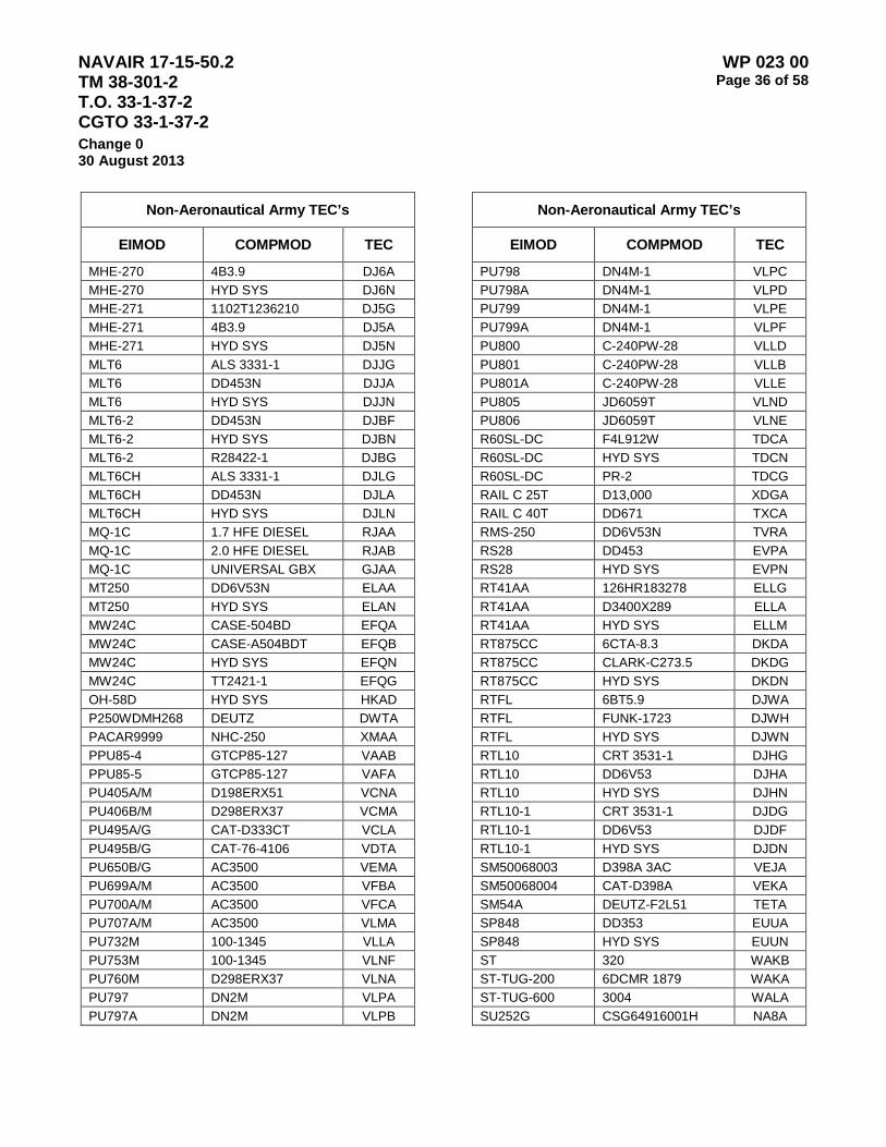
NAVAIR 17-15-50.2 TM 38-301-2 T.O. 33-1-37-2 CGTO 33-1-37-2
WP 023 00 Page 36 of 58
Change 0 30 August 2013
Non-Aeronautical Army TEC’s
EIMOD COMPMOD TEC
MHE-270 4B3.9 DJ6A MHE-270 HYD SYS DJ6N MHE-271 1102T1236210 DJ5G MHE-271 4B3.9 DJ5A MHE-271 HYD SYS DJ5N MLT6 ALS 3331-1 DJJG MLT6 DD453N DJJA MLT6 HYD SYS DJJN MLT6-2 DD453N DJBF MLT6-2 HYD SYS DJBN MLT6-2 R28422-1 DJBG MLT6CH ALS 3331-1 DJLG MLT6CH DD453N DJLA MLT6CH HYD SYS DJLN MQ-1C 1.7 HFE DIESEL RJAA MQ-1C 2.0 HFE DIESEL RJAB MQ-1C UNIVERSAL GBX GJAA MT250 DD6V53N ELAA MT250 HYD SYS ELAN MW24C CASE-504BD EFQA MW24C CASE-A504BDT EFQB MW24C HYD SYS EFQN MW24C TT2421-1 EFQG OH-58D HYD SYS HKAD P250WDMH268 DEUTZ DWTA PACAR9999 NHC-250 XMAA PPU85-4 GTCP85-127 VAAB PPU85-5 GTCP85-127 VAFA PU405A/M D198ERX51 VCNA PU406B/M D298ERX37 VCMA PU495A/G CAT-D333CT VCLA PU495B/G CAT-76-4106 VDTA PU650B/G AC3500 VEMA PU699A/M AC3500 VFBA PU700A/M AC3500 VFCA PU707A/M AC3500 VLMA PU732M 100-1345 VLLA PU753M 100-1345 VLNF PU760M D298ERX37 VLNA PU797 DN2M VLPA PU797A DN2M VLPB
Non-Aeronautical Army TEC’s
EIMOD COMPMOD TEC
PU798 DN4M-1 VLPC PU798A DN4M-1 VLPD PU799 DN4M-1 VLPE PU799A DN4M-1 VLPF PU800 C-240PW-28 VLLD PU801 C-240PW-28 VLLB PU801A C-240PW-28 VLLE PU805 JD6059T VLND PU806 JD6059T VLNE R60SL-DC F4L912W TDCA R60SL-DC HYD SYS TDCN R60SL-DC PR-2 TDCG RAIL C 25T D13,000 XDGA RAIL C 40T DD671 TXCA RMS-250 DD6V53N TVRA RS28 DD453 EVPA RS28 HYD SYS EVPN RT41AA 126HR183278 ELLG RT41AA D3400X289 ELLA RT41AA HYD SYS ELLM RT875CC 6CTA-8.3 DKDA RT875CC CLARK-C273.5 DKDG RT875CC HYD SYS DKDN RTFL 6BT5.9 DJWA RTFL FUNK-1723 DJWH RTFL HYD SYS DJWN RTL10 CRT 3531-1 DJHG RTL10 DD6V53 DJHA RTL10 HYD SYS DJHN RTL10-1 CRT 3531-1 DJDG RTL10-1 DD6V53 DJDF RTL10-1 HYD SYS DJDN SM50068003 D398A 3AC VEJA SM50068004 CAT-D398A VEKA SM54A DEUTZ-F2L51 TETA SP848 DD353 EUUA SP848 HYD SYS EUUN ST 320 WAKB ST-TUG-200 6DCMR 1879 WAKA ST-TUG-600 3004 WALA SU252G CSG64916001H NA8A

NAVAIR 17-15-50.2 TM 38-301-2 T.O. 33-1-37-2 CGTO 33-1-37-2
WP 023 00 Page 37 of 58
Change 0 30 August 2013
Non-Aeronautical Army TEC’s
EIMOD COMPMOD TEC
SU252G C-6 NA8G T449 180DAC TWWB T449 CAT-D375 TWWA TC6DO42 350LIDV85.7L NB4A TC6DO42 AT545 NB4G TC6DO42 3043LE NA3G TC6DO42 HYD SYS NB4M TMS-300-5 DD671 ELHA TMS-300-5 HYD SYS ELHN TO730HKEG 6BT5.9 E45A TO730HKEG HYD SYS E45N TUG-900 6B5.9-G1 WA2A TUG-900 KTA19-M3 WA2B UNKNOWN HYDRAULIC XXHN UNKNOWN MINERAL XXMX UNKNOWN SYNTHETIC XXSX US612ACD1 DEUTZ-91213 ZD8A PU802 C-240PW-28 VLLC PU803 JD4039T VLNB PU804 JD4039T VLNC
Non-Aeronautical Army TEC’s
EIMOD COMPMOD TEC
US90CCD1 DD353 ZHCA W150Y 28265 DJ7A W150Y AUTO79410 DJ7G W150Y HYD SYS DJ7M W15A ENDT-673 TEVA WC17 TMD NB6A WC17 W410TT NB6G WF1700/1000 DD8V92T ZM3A WF1700/1000 TD61-1168 ZM3G WPS6006 JD4039T VG6A XJJL72 RCR4.078GAEA NA3A XJJL72 3043LE NA3G XJJL72 TCR4.01BGFEK NB3B XM104 AGT-1500 ARDA XM104 X1100-3B ARDG XM104 HYD SYS ARDM

NAVAIR 17-15-50.2 TM 38-301-2 T.O. 33-1-37-2 CGTO 33-1-37-2
WP 023 00 Page 38 of 58
Change 0 30 August 2013
Table 5 – Non-Aeronautical Type Equipment Codes Army Corps of Engineers Components
Non-Aeronautical Army Corps TEC’s
EIMOD COMPMOD TEC
10235100 DD2A102916 852A 10245102 DD2A0105034 854A 10245102 DD2A0105612 853A 10245102 DD2A0106018 656A 10245102 DD2A0106038 855A 10245102 DD2A0106177 857A 175DG1803 NT-855 858A 22BM JN61 831A 250D33 CAT-D353 85DA 4031C DD4A171904 819A 500FD63D47A MT865PG270 85AA 599C DD471 81BA 67110431 LCN8 822A 71637305 DD16VA019218 85CA 71637305 DD16VA019219 85BA 76SX9E CAT-3304PC 85GA 80623400 DD6VF079684 8F1A 80827400 DD6VF079688 8F2A 80827402 DD80827402 EF3A ALEXANDER 271 893B ALEXANDER DD12V71 893A ALEXANDER MG512 893G B-40FT DD453 811A B-40FT HYD SYS 811N BAYFIELD DD671 8D7A BIENBILLE 371 8A2B BIENBILLE DD12V71 8A2A BIENBILLE MG514 8A2G BRAY DD692 81CA BRETON 15MOL3J1A 899B BRETON DD8V71 899A BRETON MH20L 899G BURRWOOD 271 898B BURRWOOD DD12V71T 898A BURRWOOD MG514 898G C-1303-24 AI45MSX8 8D3A CAT-130G 5R6192 861G CAT-130G 5R6192 862G CAT-130G CAT-3304 85HA CAT-130G CAT-3304DI 862A
Non-Aeronautical Army Corps TEC’s
EIMOD COMPMOD TEC
CAT-130G CAT-3304DIT 861A CAT-130G HYD SYS 861N CAT-130G HYD SYS 862N CAT-D4 CAT-3306 8B1A CAT-D4 CAT-7R559 8B7G CAT-D4 HYD SYS 8B1N CAT-D5 CAT-3306 8B3A CAT-D5 3S7094 8B3G CAT-D5 HYD SYS 8B3N CAT-D7E CAT-3R2211 8B2G CAT-D7E HYD SYS 8B2N CHALMETTE 8.0MDKD3CR 897B CHALMETTE DD8V71 897A CHALMETTE M20L 897G D6 CAT-D333 8B4A D7H CAT-3306B 8B6A DAVID BOYD DD8V92 89EA DULUTH AI45M5X8 8D8A DULUTH GM271G3 8D8B F800 C8.3 8C5A FAIRCHILD DD671 8D6A FORNEY DD371 8DAA FREDERICK DD271 8DBA G-1 DD353 851A GRANADA 271 896B GRANADA DD12V71T 896A GRANADA MG514 896G H60XL-MIL 360311 841G H60XL-MIL HYD SYS 841N H60XL-MIL ISUZU-C240 841A HAMMOND BAY DD671 8D4A HARVEY DD371 814A HODGE DD8V92 89CA HURON DD453 817A JD550 HYD SYS 8B5N JD550 JD4276TT01 8B5A JD550 JDAT49678 8B5G JOHN BOPP 8.0614D 895B JOHN BOPP DD8V92 895A JOHN BOPP MH20L 895G

NAVAIR 17-15-50.2 TM 38-301-2 T.O. 33-1-37-2 CGTO 33-1-37-2
WP 023 00 Page 39 of 58
Change 0 30 August 2013
Non-Aeronautical Army Corps TEC’s
EIMOD COMPMOD TEC
KENT 16V1499 8A3A KENT DD671 8A1A KENT DD671 8A3B KENT MG540 8A3G L9000 CAT-3406C 8C4A LABORDE 11.0KWD 89BA LABORDE DD8V71 894A LABORDE MH20L 894G LB-1 DD453 8E2A LB-1 HYD SYS 8E2N LT-18 GM3906 8D1A LUDINGTON GM371R641 8DCA M109A5 DD8V71T 3E7A M109A5 HYD SYS 3E7N M109A5 XTG-411-2A 3E7G M109A6 DD8V71T 3FCA M109A6 HYD SYS 3FCN M109A6 XTG-411-4 3FCG M4K CASE-207D 8C1A M4K CLK18340 8C1G M4K HYD SYS 8C1N M50A1 DD671 8C2A M578 DD8V71T 3LAA M578 HYD SYS 3LAN M578 XTG-411-2A 3LAG MANITOWAC DD353 812A MT250 HYD SYS 831N MW24C CASE-504BD 871A MW24C HYD SYS 871N MW24C TT24211 871G N CENTRAL DD8V71 89FA NI9752 DD671 83CA NICOLET DD471 818A P38 DD853 891A PAJ DD8V92 89DA PB-1 GMC871 881A PU406A/M D298ERX37 85FA RACINE DD353 8D2A RG4031C DD4A171903 81AA RT855B CAT-3116 832A RT855B HYD SYS 832M
Non-Aeronautical Army Corps TEC’s
EIMOD COMPMOD TEC
RT855B R32620-4 832G RTCH-MC 3P9094 MDAW RTCH-MC CAT-3408T MDAC RTCH-MC CAT-5R3855 MDAJ RTCH-MC HYD SYS MDAN S2200 NTC-240 8C3B S2200 NTC-300 8C3C S2200 NTC-855 8C3A SCOW #31 DD6068 815A SCOW #32 DD671 816A SHOALHUNTER CAT-3406B 824A SPD-1 DD371 8E4A SPD-1 DD6V71 8E4B SR-4 CAT-3304 85EA TAWAS BAY DDD671 8D9A TBCL4 DD16V149 8A4A TBCL4 DD671 8A4B TBCL4 MG540 8A4G TD-15C IHDT-466B 8B8A UPS-8 DD671 81DA USCCBMK1 363CI 821A VELER DD371 813A W-38 DDC671 892A W-38 MG509 892G W-46 8.0MKDB/1 89AB W-46 M20L 89AG W-48 DD8V71 89AA WHITEFISH DD12V71 8D5A XM93FOX HP500 TYPE 6 559G XM93FOX HYD SYS 559N XM93FOX OM402A 559A YF-865 DD371 8E6A YF-865 DD6V149 8E6B YSD-22 DD12V71 8E3A YSD-22 DD471 8E3B YSD-59 DD12V71 8E5A YSD-59 DD471 8E5B YSD-67 DD671 823B YSD-67 NTA855M 823A YSD-78 DD353 8E7A YSD-78 DD371 8E7B
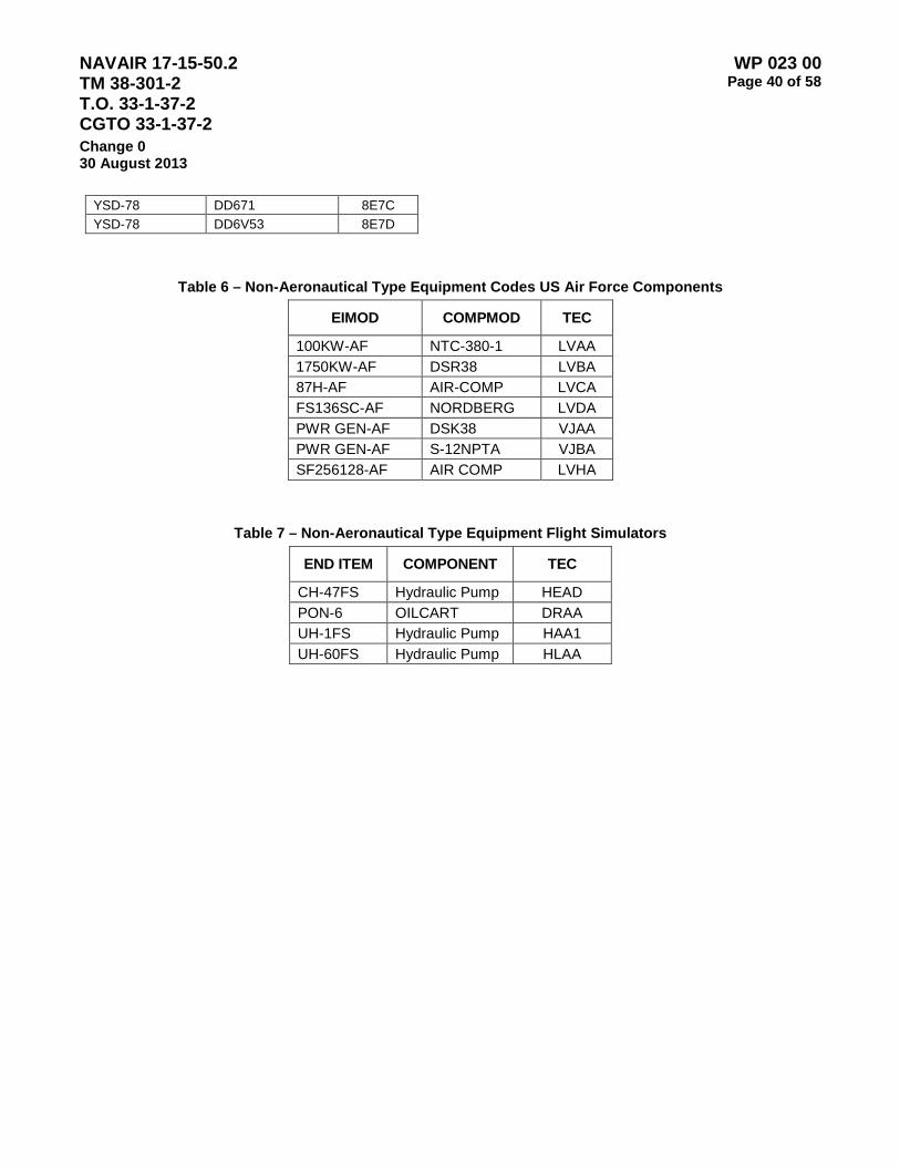
NAVAIR 17-15-50.2 TM 38-301-2 T.O. 33-1-37-2 CGTO 33-1-37-2
WP 023 00 Page 40 of 58
Change 0 30 August 2013
YSD-78 DD671 8E7C YSD-78 DD6V53 8E7D
Table 6 – Non-Aeronautical Type Equipment Codes US Air Force Components
EIMOD COMPMOD TEC
100KW-AF NTC-380-1 LVAA 1750KW-AF DSR38 LVBA 87H-AF AIR-COMP LVCA FS136SC-AF NORDBERG LVDA PWR GEN-AF DSK38 VJAA PWR GEN-AF S-12NPTA VJBA SF256128-AF AIR COMP LVHA
Table 7 – Non-Aeronautical Type Equipment Flight Simulators
END ITEM COMPONENT TEC
CH-47FS Hydraulic Pump HEAD PON-6 OILCART DRAA UH-1FS Hydraulic Pump HAA1 UH-60FS Hydraulic Pump HLAA

NAVAIR 17-15-50.2 TM 38-301-2 T.O. 33-1-37-2 CGTO 33-1-37-2
WP 023 00 Page 41 of 58
Change 0 30 August 2013
Table 8 – Non-Aeronautical Type Equipment US Navy Ships Equipment
Non-Aeronautical TEC’s US Navy Ships Equipment
End Item Component TEC
ANCHORS
ALL ANCHOR HYDRAULIC 1A01 ALL ANCHOR 80-90 1A02
CRANES
ALL CRANE 80-90 2A01 ALL CRANE HYDRAULIC 2A02 ALL CRANE 9250 2A03
HYDRAULIC EQUIPMENT
ALL HYDRAULIC POWER UNIT 3A01 AIR CONDITIONING AND REFRIGERATION
ALL AIR CONDITIONING/REFRIGERATION SW 68 4001 ALL AIR CONDITIONING/REFRIGERATION RC02 4002 ALL AIR CONDITIONING/REFRIGERATION RC04 4003 ALL AIR CONDITIONING/REFRIGERATION POE 48 4004
MISCELLANEOUS EQUIPMENT
ALL MISCELLANEOUS EQUIPMENT 2190 5A01 ALL MISCELLANEOUS EQUIPMENT 9250 5A02 ALL MISCELLANEOUS EQUIPMENT 23699 5A03 ALL MISCELLANEOUS EQUIPMENT HYDRAULIC 5A04 ALL MISCELLANEOUS EQUIPMENT 80-90 5A05
BLOWERS
ALL BLOWER 2190 6A0Y TURBO CHARGERS

NAVAIR 17-15-50.2 TM 38-301-2 T.O. 33-1-37-2 CGTO 33-1-37-2
WP 023 00 Page 42 of 58
Change 0 30 August 2013
Non-Aeronautical TEC’s US Navy Ships Equipment
End Item Component TEC
ALL TURBO CHARGERS 9250 7001
MISC GENERATORS
ALL MISC GENERATORS 9250 8001 ALL MISC GENERATORS 2190 8002
AIR COMPRESSORS
ALL AIR COMPRESSORS 2190 AA01 ALL AIR COMPRESSORS 9250 AA02 ALL AIR COMPRESSORS 23699 AA03 ALL AIR COMPRESSORS HYDRAULIC AA04
BEARINGS
ALL BEARINGS 2190 B001 CONTROLLABLE PITCH PROPELLERS
AOE 6 Class ROLLS ROYCE NAVY MARINES 245-6361975 C41M ARS 50 Class ROLLS ROYCE NAVY MARINES 7309 C50M CG 47 Class ROLLS ROYCE NAVY MARINES 115652102 C80M CG 66 Class ROLLS ROYCE NAVY MARINES 115652103 C8AM DD 963 Class ROLLS ROYCE NAVY MARINES 7309 CF0M DDG 51 Class ROLLS ROYCE NAVY MARINES 7309 CF1M DDG 993 Class ROLLS ROYCE NAVY MARINES 115657001 CF2M
FFG 7 Class ROLLS ROYCE NAVY MARINES 7309 CG0M LCAC Class DOWDY CO. LTD. CH0N LHD 1 Class ROLLS ROYCE NAVY MARINES 80-3S-CP CI1M LSD 41 Class ROLLS ROYCE NAVY MARINES 112152001 CN0M LSD 49 Class ROLLS ROYCE NAVY MARINES 112157071 CP0M
LST 1179 Class ROLLS ROYCE NAVY MARINES DWG110251003PORT CQ0M
MCM 1 Class ROLLS ROYCE NAVY MARINES 7309 CR0M MISC Class MISC CPP CH5M
WAGB 10 Class ROLLS ROYCE NAVY MARINES CU0M
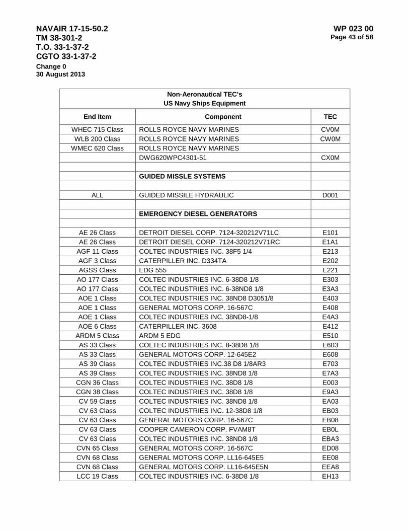
NAVAIR 17-15-50.2 TM 38-301-2 T.O. 33-1-37-2 CGTO 33-1-37-2
WP 023 00 Page 43 of 58
Change 0 30 August 2013
Non-Aeronautical TEC’s US Navy Ships Equipment
End Item Component TEC
WHEC 715 Class ROLLS ROYCE NAVY MARINES CV0M WLB 200 Class ROLLS ROYCE NAVY MARINES CW0M
WMEC 620 Class ROLLS ROYCE NAVY MARINES DWG620WPC4301-51 CX0M GUIDED MISSLE SYSTEMS
ALL GUIDED MISSILE HYDRAULIC D001 EMERGENCY DIESEL GENERATORS
AE 26 Class DETROIT DIESEL CORP. 7124-320212V71LC E101 AE 26 Class DETROIT DIESEL CORP. 7124-320212V71RC E1A1
AGF 11 Class COLTEC INDUSTRIES INC. 38F5 1/4 E213 AGF 3 Class CATERPILLER INC. D334TA E202 AGSS Class EDG 555 E221
AO 177 Class COLTEC INDUSTRIES INC. 6-38D8 1/8 E303 AO 177 Class COLTEC INDUSTRIES INC. 6-38ND8 1/8 E3A3 AOE 1 Class COLTEC INDUSTRIES INC. 38ND8 D3051/8 E403 AOE 1 Class GENERAL MOTORS CORP. 16-567C E408 AOE 1 Class COLTEC INDUSTRIES INC. 38ND8-1/8 E4A3 AOE 6 Class CATERPILLER INC. 3608 E412
ARDM 5 Class ARDM 5 EDG E510 AS 33 Class COLTEC INDUSTRIES INC. 8-38D8 1/8 E603 AS 33 Class GENERAL MOTORS CORP. 12-645E2 E608 AS 39 Class COLTEC INDUSTRIES INC.38 D8 1/8AR3 E703 AS 39 Class COLTEC INDUSTRIES INC. 38ND8 1/8 E7A3
CGN 36 Class COLTEC INDUSTRIES INC. 38D8 1/8 E003 CGN 38 Class COLTEC INDUSTRIES INC. 38D8 1/8 E9A3 CV 59 Class COLTEC INDUSTRIES INC. 38ND8 1/8 EA03 CV 63 Class COLTEC INDUSTRIES INC. 12-38D8 1/8 EB03 CV 63 Class GENERAL MOTORS CORP. 16-567C EB08 CV 63 Class COOPER CAMERON CORP. FVAM8T EB0L CV 63 Class COLTEC INDUSTRIES INC. 38ND8 1/8 EBA3
CVN 65 Class GENERAL MOTORS CORP. 16-567C ED08 CVN 68 Class GENERAL MOTORS CORP. LL16-645E5 EE08 CVN 68 Class GENERAL MOTORS CORP. LL16-645E5N EEA8 LCC 19 Class COLTEC INDUSTRIES INC. 6-38D8 1/8 EH13

NAVAIR 17-15-50.2 TM 38-301-2 T.O. 33-1-37-2 CGTO 33-1-37-2
WP 023 00 Page 44 of 58
Change 0 30 August 2013
Non-Aeronautical TEC’s US Navy Ships Equipment
End Item Component TEC
LHA 1 Class COLTEC INDUSRIES INC. 251C EI03 LHD 1 Class COLTEC INDUSTRIES INC. 251C EI13 LPD 1 Class COLTEC INDUSTRIES INC. 38F5 1/4 EJ03 LPD 14 Class DETROIT DIESEL CORP. 7123-730012V71RC EL01 LPD 7 Class COLTEC INDUSTRIES INC. 38F5 1/4 EK03 LSD 36 Class DETROIT DIESEL CORP. 7123-730012V71RC EM01 MCM Class MCM EDG ER00
MCS 12 Class COLTEC INDUSTRIES INC. 12-38D8 1/8 ER13 ALL MISC EDG EH50
SSBN 726 Class COLTEC INDUSTRIES INC. 38ND8 1/8 ET03 SSN 21 Class COLTEC INDUSTRIES INC. 38ND8 1/8 ET13 SSN 637 Class COLTEC INDUSTRIES INC. 38F5 1/4 ET23 SSN 640 Class COLTEC INDUSTRIES INC. 38F5 1/4 ET33 SSN 671 Class COLTEC INDUSTRIES INC. 38F5 1/4 ET43 SSN 688 Class COLTEC INDUSTRIES INC. 38ND8 1/8 ET53 WAGB 10 Class DETROIT DIESEL CORP. 16V149 EU01 WLB 200 Class CATERPILLER INC. 3406TA EW02 WLB 277 Class DETROIT DIESEL CORP. 8V-71 EW11 WLB 277 Class CATERPILLER INC. 3306DI EW12 WLIC 298 Class DETROIT DIESEL CORP. #6-71 EW51
WLIC 75301 Class DETROIT DIESEL CORP. #4-71 EW61 WLIC 75301 Class DETROIT DIESEL CORP. #6-71 EWB1
WLM 540 Class CATERPILLER INC. 406T EW82 WLR 311 Class DETROIT DIESEL CORP. #3-53 EW91
WLR 75401 Class DETROIT DIESEL CORP. #4-71 EWY1 WMEC Class CATERPILLER INC. 3306 EX02 WMEC Class CATERPILLER INC. D348TA EXA2
FIN STABLIZIERS
ALL FIN STABILIZER HYDRAULIC F001 GAS TURBINE ENGINES
AOE 6 Class GENERAL ELECTRIC CO LM2500 G41O CG 47 Class STEWART & STEVENSON SERVICES INC 139A200 G80J CG 47 Class GENERAL ELECTRIC CO LM2500 G80O DD 963 Class ROLLS ROYCE NAVY MARINES 501-K17 GF0M
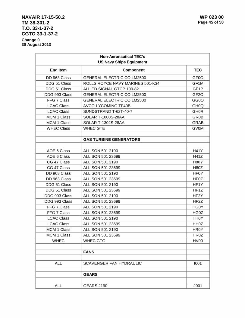
NAVAIR 17-15-50.2 TM 38-301-2 T.O. 33-1-37-2 CGTO 33-1-37-2
WP 023 00 Page 45 of 58
Change 0 30 August 2013
Non-Aeronautical TEC’s US Navy Ships Equipment
End Item Component TEC
DD 963 Class GENERAL ELECTRIC CO LM2500 GF0O DDG 51 Class ROLLS ROYCE NAVY MARINES 501-K34 GF1M DDG 51 Class ALLIED SIGNAL GTCP 100-82 GF1P DDG 993 Class GENERAL ELECTRIC CO LM2500 GF2O
FFG 7 Class GENERAL ELECTRIC CO LM2500 GG0O LCAC Class AVCO-LYCOMING TF40B GH0Q LCAC Class SUNDSTRAND T-62T-40-7 GH0R MCM 1 Class SOLAR T-1000S-28AA GR0B MCM 1 Class SOLAR T-1302S-28AA GRAB WHEC Class WHEC GTE GV0M
GAS TURBINE GENERATORS
AOE 6 Class ALLISON 501 2190 H41Y AOE 6 Class ALLISON 501 23699 H41Z CG 47 Class ALLISON 501 2190 H80Y CG 47 Class ALLISON 501 23699 H80Z DD 963 Class ALLISON 501 2190 HF0Y DD 963 Class ALLISON 501 23699 HF0Z DDG 51 Class ALLISON 501 2190 HF1Y DDG 51 Class ALLISON 501 23699 HF1Z DDG 993 Class ALLISON 501 2190 HF2Y DDG 993 Class ALLISON 501 23699 HF2Z
FFG 7 Class ALLISON 501 2190 HG0Y FFG 7 Class ALLISON 501 23699 HG0Z LCAC Class ALLISON 501 2190 HH0Y LCAC Class ALLISON 501 23699 HH0Z MCM 1 Class ALLISON 501 2190 HR0Y MCM 1 Class ALLISON 501 23699 HR0Z
WHEC WHEC GTG HV00 FANS
ALL SCAVENGER FAN HYDRAULIC I001 GEARS
ALL GEARS 2190 J001

NAVAIR 17-15-50.2 TM 38-301-2 T.O. 33-1-37-2 CGTO 33-1-37-2
WP 023 00 Page 46 of 58
Change 0 30 August 2013
Non-Aeronautical TEC’s US Navy Ships Equipment
End Item Component TEC
ALL GEARS 80-90 J002 ALL GEARS 23699 J003 ALL GEARS HYDRAULIC J004 ALL GEARS 9250 J005
ROCKER ARMS
LSD 36 CLASS COLTEC IND. INC. DIESEL ENG ROCKER ARMS KM03 LSD 41 CLASS COLTEC IND. INC. DIESEL ENG ROCKER ARMS KN03 LSD 49 CLASS COLTEC IND. INC. DIESEL ENG ROCKER ARMS KP03
ELEVATORS NON HYDRAULIC
CG 47 CLASS CG 47 ELEVATOR-NON HYDRAULIC L800 CV 63 CLASS WESTINGHOUSE LB07 CV 63 CLASS JARED INDUSTRIES INC LB0A CV 63 CLASS OTIS ELEVATOR CO LB0D
CVN 65 WESTINGHOUSE LD07 CVN 68 CLASS JARED INDUSTRIES INC LE0A CVN 68 CLASS RUCKER LE0E DD 963 CLASS DD 963 ELEVATOR NON HYDRAULIC LF00 FFG 7 CLASS FFG7 ELEVATOR NON HYDRAULIC LG00 LHA 1 CLASS JARED INDUSTRIES INC LI0A LHA 1 CLASS LHA1 ELEVATOR NON HYDRUALIC LI00 LHD 1 CLASS SCHINDLER ELEVATOR CORP LI0S LPD 7 CLASS LPD 7 ELEVATOR-NON HYDRAULIC LK00
MCS 12 CLASS JARED INDUSTRIES INC LR1A ELEVATORS HYDRAULIC
CG 47 CLASS CG 47 ELEVATOR HYDARULIC L8A0 CV 63 CLASS WESTINGHOUSE LBA7 CV 63 CLASS OTIS ELEVATOR CO LBAA CV 63 CLASS JARED INDUSTRIED INC LBAD
CVN 65 WESTINGHOUSE LDA7 CVN 68 CLASS RUCKER LEAA CVN 68 CLASS JARED INDUSTRIED INC LEAE
DD 963 DD 963 ELEVATOR HYDRAULI LFA0
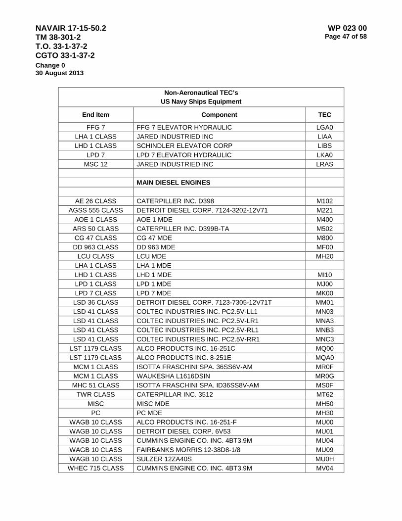
NAVAIR 17-15-50.2 TM 38-301-2 T.O. 33-1-37-2 CGTO 33-1-37-2
WP 023 00 Page 47 of 58
Change 0 30 August 2013
Non-Aeronautical TEC’s US Navy Ships Equipment
End Item Component TEC
FFG 7 FFG 7 ELEVATOR HYDRAULIC LGA0 LHA 1 CLASS JARED INDUSTRIED INC LIAA LHD 1 CLASS SCHINDLER ELEVATOR CORP LIBS
LPD 7 LPD 7 ELEVATOR HYDRAULIC LKA0 MSC 12 JARED INDUSTRIED INC LRAS
MAIN DIESEL ENGINES
AE 26 CLASS CATERPILLER INC. D398 M102 AGSS 555 CLASS DETROIT DIESEL CORP. 7124-3202-12V71 M221
AOE 1 CLASS AOE 1 MDE M400 ARS 50 CLASS CATERPILLER INC. D399B-TA M502 CG 47 CLASS CG 47 MDE M800 DD 963 CLASS DD 963 MDE MF00
LCU CLASS LCU MDE MH20 LHA 1 CLASS LHA 1 MDE LHD 1 CLASS LHD 1 MDE MI10 LPD 1 CLASS LPD 1 MDE MJ00 LPD 7 CLASS LPD 7 MDE MK00 LSD 36 CLASS DETROIT DIESEL CORP. 7123-7305-12V71T MM01 LSD 41 CLASS COLTEC INDUSTRIES INC. PC2.5V-LL1 MN03 LSD 41 CLASS COLTEC INDUSTRIES INC. PC2.5V-LR1 MNA3 LSD 41 CLASS COLTEC INDUSTRIES INC. PC2.5V-RL1 MNB3 LSD 41 CLASS COLTEC INDUSTRIES INC. PC2.5V-RR1 MNC3
LST 1179 CLASS ALCO PRODUCTS INC. 16-251C MQ00 LST 1179 CLASS ALCO PRODUCTS INC. 8-251E MQA0 MCM 1 CLASS ISOTTA FRASCHINI SPA. 36SS6V-AM MR0F MCM 1 CLASS WAUKESHA L1616DSIN MR0G MHC 51 CLASS ISOTTA FRASCHINI SPA. ID36SS8V-AM MS0F
TWR CLASS CATERPILLAR INC. 3512 MT62 MISC MISC MDE MH50 PC PC MDE MH30
WAGB 10 CLASS ALCO PRODUCTS INC. 16-251-F MU00 WAGB 10 CLASS DETROIT DIESEL CORP. 6V53 MU01 WAGB 10 CLASS CUMMINS ENGINE CO. INC. 4BT3.9M MU04 WAGB 10 CLASS FAIRBANKS MORRIS 12-38D8-1/8 MU09 WAGB 10 CLASS SULZER 12ZA40S MU0H WHEC 715 CLASS CUMMINS ENGINE CO. INC. 4BT3.9M MV04
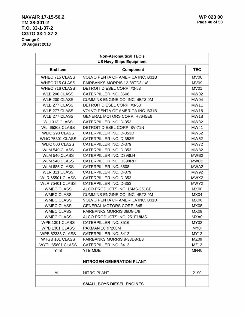
NAVAIR 17-15-50.2 TM 38-301-2 T.O. 33-1-37-2 CGTO 33-1-37-2
WP 023 00 Page 48 of 58
Change 0 30 August 2013
Non-Aeronautical TEC’s US Navy Ships Equipment
End Item Component TEC
WHEC 715 CLASS VOLVO PENTA OF AMERICA INC. B31B MV06 WHEC 715 CLASS FAIRBANKS MORRIS 12-38TD8-1/8 MV09 WHEC 716 CLASS DETROIT DIESEL CORP. #3-53 MV01 WLB 200 CLASS CATERPILLER INC. 3608 MW02 WLB 200 CLASS CUMMINS ENGINE CO. INC. 4BT3.9M MW04 WLB 277 CLASS DETROIT DIESEL CORP. #3-53 MW11 WLB 277 CLASS VOLVO PENTA OF AMERICA INC. B31B MW16 WLB 277 CLASS GENERAL MOTORS CORP. R8645E6 MW18 WLI 313 CLASS CATERPILLER INC. D-353 MW32
WLI 65303 CLASS DETROIT DIESEL CORP. 8V-71N MW41 WLIC 298 CLASS CATERPILLER INC. D-353D MW52
WLIC 75301 CLASS CATERPILLER INC. D-353E MW62 WLIC 800 CLASS CATERPILLER INC. D-379 MW72 WLM 540 CLASS CATERPILLER INC. D-353 MW82 WLM 540 CLASS CATERPILLER INC. D398LH MWB2 WLM 540 CLASS CATERPILLER INC. D398RH MWC2 WLM 685 CLASS CATERPILLER INC. 3508 MWA2 WLR 311 CLASS CATERPILLER INC. D-379 MW92
WLR 65501 CLASS CATERPILLER INC. D-353 MWX2 WLR 75401 CLASS CATERPILLER INC. D-353 MWY2
WMEC CLASS ALCO PRODUCTS INC. 16MS-251CE MX00 WMEC CLASS CUMMINS ENGINE CO. INC. 4BT3.9M MX04 WMEC CLASS VOLVO PENTA OF AMERICA INC. B31B MX06 WMEC CLASS GENERAL MOTORS CORP. 645 MX08 WMEC CLASS FAIRBANKS MORRIS 38D8-1/8 MX09 WMEC CLASS ALCO PRODUCTS INC. 251F18MS MXA0
WPB 1301 CLASS CATERPILLER INC. 3516 MY02 WPB 1301 CLASS PAXMAN 16RP200M MY0I WPB 82333 CLASS CATERPILLER INC. 3412 MY12 WTGB 101 CLASS FAIRBANKS MORRIS 8-38D8-1/8 MZ09
WYTL 65601 CLASS CATERPILLER INC. 3412 MZ12 YTB YTB MDE MH40
NITROGEN GENERATION PLANT
ALL NITRO PLANT 2190 SMALL BOYS DIESEL ENGINES

NAVAIR 17-15-50.2 TM 38-301-2 T.O. 33-1-37-2 CGTO 33-1-37-2
WP 023 00 Page 49 of 58
Change 0 30 August 2013
Non-Aeronautical TEC’s US Navy Ships Equipment
End Item Component TEC
AE 26 CLASS DETROIT DIESEL CORP. 5042-40004-53LD O101 AE 26 CLASS CUMMINS ENGINE CO. INC. 6BTA5.9-M O104 AE 26 CLASS WESTERBEKE CORP. 108O-14088 O105 AE 26 CLASS DETROIT DIESEL CORP. 5062-70006V53N O1A1 AE 26 CLASS WESTERBEKE CORP.4 –107 O1A5 AE 26 CLASS DETROIT DIESEL CORP. 6087M-ALUM O1B1 AE 26 CLASS DETROIT DIESEL CORP. 6-71RD706087M O1C1
AGF 11 CLASS DETROIT DIESEL CORP. 6121T6-71LC O211 AGF 11 CLASS WESTERBEKE CORP. 108U-14088 O215 AGF 3 CLASS DETROIT DIESEL CORP. 1062-7000 O201 AGF 3 CLASS WESTERBEKE CORP. 108O-14088 O205 AGF 3 CLASS DETROIT DIESEL CORP. 6072M6-71RC O2A1 AGF 3 CLASS DETROIT DIESEL CORP. 7082-7399 O2B1 AO 177 CLASS DETROIT DIESEL CORP. 1062-7000 O301 AO 177 CLASS CUMMINS ENGINE CO. INC. 6BTA5.9-M O304 AO 177 CLASS VOLVO PENTA OF AMERICA INC AQAD41A-DP290A O306 AO 177 CLASS DETROIT DIESEL CORP. 6072M6-71RC O3A1 AOE 1 CLASS DETROIT DIESEL CORP. 1062-7000 O401 AOE 1 CLASS CUMMINS ENGINE CO. INC. 6BTA5.9-M O404 AOE 1 CLASS WESTERBEKE CORP. 108U-14088 O405 AOE 1 CLASS DETROIT DIESEL CORP. 5062-70006V53N O4A1 AOE 1 CLASS CUMMINS ENGINE CO. INC. 6BTA5.9-M O4A4 AOE 1 CLASS WESTERBEKE CORP. 14088 SPEC B O4A5 AOE 1 CLASS DETROIT DIESEL CORP. 64HN9HTEXCH O4B1 AOE 1 CLASS DETROIT DIESEL CORP. 64HN9KCLG O4C1 AOE 6 CLASS DETROIT DIESEL CORP. 1062-7000 O411 AOE 6 CLASS CUMMINS ENGINE CO. INC. 4B3.9-M O414 AOE 6 CLASS VOLVO PENTA OF AMERICA INC AQAD41A-DP290A O416 AOE 6 CLASS CUMMINS ENGINE CO. INC. 6BTA5.9-M O4B4 AOE 6 CLASS CUMMINS ENGINE CO. INC. 6BTA5.9-M2 O4C4 AOE 6 CLASS DETROIT DIESEL CORP. 6072M6-71RC O4D1 ARS 50 CLASS DETROIT DIESEL CORP. 5042-40004-53LD O501 ARS 50 CLASS DETROIT DIESEL CORP. 5042-40004-53RB O5A1 AS 33 CLASS DETROIT DIESEL CORP. 1062-5000 O601 AS 33 CLASS CUMMINS ENGINE CO. INC. 6BTA5.9-M2 O604 AS 33 CLASS WESTERBEKE CORP. 4-107 O605 AS 33 CLASS ONAN CORP. 1.5OMDJF4R4686D O60C

NAVAIR 17-15-50.2 TM 38-301-2 T.O. 33-1-37-2 CGTO 33-1-37-2
WP 023 00 Page 50 of 58
Change 0 30 August 2013
Non-Aeronautical TEC’s US Navy Ships Equipment
End Item Component TEC
AS 33 CLASS DETROIT DIESEL CORP. 1062-5099 O6A1 AS 33 CLASS ONAN CORP. 1.5OMDJF4R4686D O6AC AS 33 CLASS DETROIT DIESEL CORP. 1062-7000 O6B1 AS 33 CLASS DETROIT DIESEL CORP. 6072M6-71RC O6C1 AS 33 CLASS DETROIT DIESEL CORP. 64HN9HTEXCH O6D1 AS 39 CLASS DETROIT DIESEL CORP. 1043-7005 O701 AS 39 CLASS COLTEC INDUSTRIES INC. 38D8 1/8AR3 O703 AS 39 CLASS WESTERBEKE CORP. 14088 SPEC B O705 AS 39 CLASS DETROIT DIESEL CORP. 1043-7005-4-71N O7A1 AS 39 CLASS WESTERBEKE CORP. 4-107 O7A5 AS 39 CLASS DETROIT DIESEL CORP. 1062-5099 O7B1 AS 39 CLASS DETROIT DIESEL CORP. 1062-6001 O7C1 AS 39 CLASS DETROIT DIESEL CORP. 5062-7000 O7D1 AS 39 CLASS DETROIT DIESEL CORP. 5062-70006V53N O7E1 AS 39 CLASS DETROIT DIESEL CORP. 6072M6-71RC O7F1 AS 39 CLASS DETROIT DIESEL CORP. 6088M O7G1 CG 47 CLASS DETROIT DIESEL CORP. 5062-3000 O801 CG 47 CLASS CUMMINS ENGINE CO. INC. 6BTA5.9-M O804 CG 47 CLASS VOLVO PENTA OF AMERICA INC AQAD41A-DP290A O806 CG 47 CLASS DETROIT DIESEL CORP. 5062-70006V53N O8A1
CGN 36 CLASS DETROIT DIESEL CORP. 1062-7000 O901 CGN 36 CLASS CUMMINS ENGINE CO. INC. 8BTA5.9-M O904 CGN 36 CLASS WESTERBEKE CORP. 108D-14088 O905 CGN 36 CLASS DETROIT DIESEL CORP. 5062-70006V53N O9A1 CGN 36 CLASS WESTERBEKE CORP. 14088 SPEC B O9A5 CGN 38 CLASS DETROIT DIESEL CORP. 5042-3000 O001 CGN 38 CLASS WESTERBEKE CORP. 4-107 O005 CGN 38 CLASS DETROIT DIESEL CORP. 5042-40004-53LD O0A1 CV 59 CLASS DETROIT DIESEL CORP. 6087M-STBD OA01 CV 59 CLASS WESTERBEKE CORP. 108U-14088 OA05 CV 59 CLASS VOLVO PENTA OF AMERICA INC AQAD41A-DP290A OA06 CV 59 CLASS DETROIT DIESEL CORP 6088M PORT OAA1 CV 59 CLASS WESTERBEKE CORP. 4-107 OAA5 CV 59 CLASS DETROIT DIESEL CORP. 64HNTEXCH OAB1 CV 59 CLASS DETROIT DIESEL CORP. 6-71RA6071MB OAC1 CV 63 CLASS DETROIT DIESEL CORP. 1062-7000 OB01 CV 63 CLASS WESTERBEKE CORP. 4-107 OB05 CV 63 CLASS VOLVO PENTA OF AMERICA INC AQAD41A-DP290A OB06
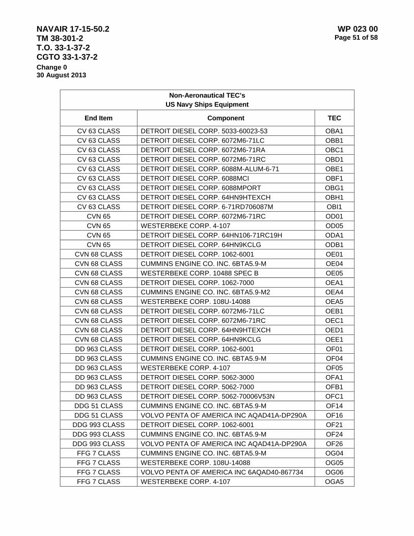
NAVAIR 17-15-50.2 TM 38-301-2 T.O. 33-1-37-2 CGTO 33-1-37-2
WP 023 00 Page 51 of 58
Change 0 30 August 2013
Non-Aeronautical TEC’s US Navy Ships Equipment
End Item Component TEC
CV 63 CLASS DETROIT DIESEL CORP. 5033-60023-53 OBA1 CV 63 CLASS DETROIT DIESEL CORP. 6072M6-71LC OBB1 CV 63 CLASS DETROIT DIESEL CORP. 6072M6-71RA OBC1 CV 63 CLASS DETROIT DIESEL CORP. 6072M6-71RC OBD1 CV 63 CLASS DETROIT DIESEL CORP. 6088M-ALUM-6-71 OBE1 CV 63 CLASS DETROIT DIESEL CORP. 6088MCI OBF1 CV 63 CLASS DETROIT DIESEL CORP. 6088MPORT OBG1 CV 63 CLASS DETROIT DIESEL CORP. 64HN9HTEXCH OBH1 CV 63 CLASS DETROIT DIESEL CORP. 6-71RD706087M OBI1
CVN 65 DETROIT DIESEL CORP. 6072M6-71RC OD01 CVN 65 WESTERBEKE CORP. 4-107 OD05 CVN 65 DETROIT DIESEL CORP. 64HN106-71RC19H ODA1 CVN 65 DETROIT DIESEL CORP. 64HN9KCLG ODB1
CVN 68 CLASS DETROIT DIESEL CORP. 1062-6001 OE01 CVN 68 CLASS CUMMINS ENGINE CO. INC. 6BTA5.9-M OE04 CVN 68 CLASS WESTERBEKE CORP. 10488 SPEC B OE05 CVN 68 CLASS DETROIT DIESEL CORP. 1062-7000 OEA1 CVN 68 CLASS CUMMINS ENGINE CO. INC. 6BTA5.9-M2 OEA4 CVN 68 CLASS WESTERBEKE CORP. 108U-14088 OEA5 CVN 68 CLASS DETROIT DIESEL CORP. 6072M6-71LC OEB1 CVN 68 CLASS DETROIT DIESEL CORP. 6072M6-71RC OEC1 CVN 68 CLASS DETROIT DIESEL CORP. 64HN9HTEXCH OED1 CVN 68 CLASS DETROIT DIESEL CORP. 64HN9KCLG OEE1 DD 963 CLASS DETROIT DIESEL CORP. 1062-6001 OF01 DD 963 CLASS CUMMINS ENGINE CO. INC. 6BTA5.9-M OF04 DD 963 CLASS WESTERBEKE CORP. 4-107 OF05 DD 963 CLASS DETROIT DIESEL CORP. 5062-3000 OFA1 DD 963 CLASS DETROIT DIESEL CORP. 5062-7000 OFB1 DD 963 CLASS DETROIT DIESEL CORP. 5062-70006V53N OFC1 DDG 51 CLASS CUMMINS ENGINE CO. INC. 6BTA5.9-M OF14 DDG 51 CLASS VOLVO PENTA OF AMERICA INC AQAD41A-DP290A OF16 DDG 993 CLASS DETROIT DIESEL CORP. 1062-6001 OF21 DDG 993 CLASS CUMMINS ENGINE CO. INC. 6BTA5.9-M OF24 DDG 993 CLASS VOLVO PENTA OF AMERICA INC AQAD41A-DP290A OF26
FFG 7 CLASS CUMMINS ENGINE CO. INC. 6BTA5.9-M OG04 FFG 7 CLASS WESTERBEKE CORP. 108U-14088 OG05 FFG 7 CLASS VOLVO PENTA OF AMERICA INC 6AQAD40-867734 OG06 FFG 7 CLASS WESTERBEKE CORP. 4-107 OGA5
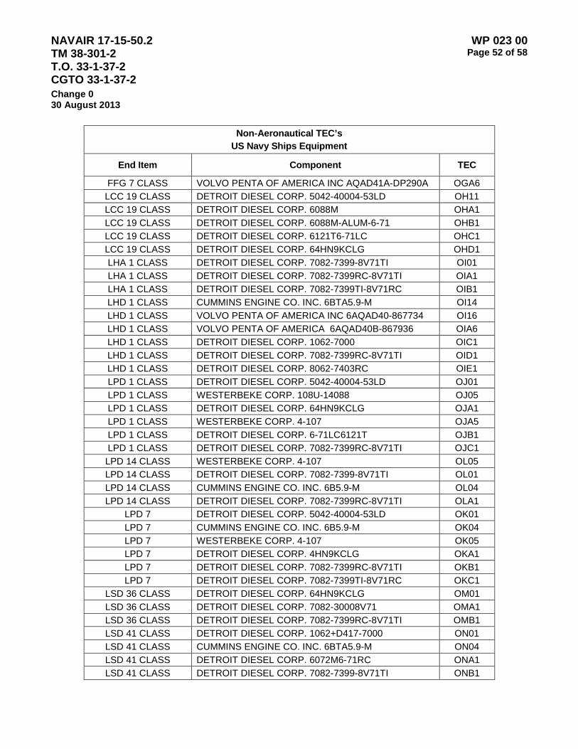
NAVAIR 17-15-50.2 TM 38-301-2 T.O. 33-1-37-2 CGTO 33-1-37-2
WP 023 00 Page 52 of 58
Change 0 30 August 2013
Non-Aeronautical TEC’s US Navy Ships Equipment
End Item Component TEC
FFG 7 CLASS VOLVO PENTA OF AMERICA INC AQAD41A-DP290A OGA6 LCC 19 CLASS DETROIT DIESEL CORP. 5042-40004-53LD OH11 LCC 19 CLASS DETROIT DIESEL CORP. 6088M OHA1 LCC 19 CLASS DETROIT DIESEL CORP. 6088M-ALUM-6-71 OHB1 LCC 19 CLASS DETROIT DIESEL CORP. 6121T6-71LC OHC1 LCC 19 CLASS DETROIT DIESEL CORP. 64HN9KCLG OHD1 LHA 1 CLASS DETROIT DIESEL CORP. 7082-7399-8V71TI OI01 LHA 1 CLASS DETROIT DIESEL CORP. 7082-7399RC-8V71TI OIA1 LHA 1 CLASS DETROIT DIESEL CORP. 7082-7399TI-8V71RC OIB1 LHD 1 CLASS CUMMINS ENGINE CO. INC. 6BTA5.9-M OI14 LHD 1 CLASS VOLVO PENTA OF AMERICA INC 6AQAD40-867734 OI16 LHD 1 CLASS VOLVO PENTA OF AMERICA 6AQAD40B-867936 OIA6 LHD 1 CLASS DETROIT DIESEL CORP. 1062-7000 OIC1 LHD 1 CLASS DETROIT DIESEL CORP. 7082-7399RC-8V71TI OID1 LHD 1 CLASS DETROIT DIESEL CORP. 8062-7403RC OIE1 LPD 1 CLASS DETROIT DIESEL CORP. 5042-40004-53LD OJ01 LPD 1 CLASS WESTERBEKE CORP. 108U-14088 OJ05 LPD 1 CLASS DETROIT DIESEL CORP. 64HN9KCLG OJA1 LPD 1 CLASS WESTERBEKE CORP. 4-107 OJA5 LPD 1 CLASS DETROIT DIESEL CORP. 6-71LC6121T OJB1 LPD 1 CLASS DETROIT DIESEL CORP. 7082-7399RC-8V71TI OJC1 LPD 14 CLASS WESTERBEKE CORP. 4-107 OL05 LPD 14 CLASS DETROIT DIESEL CORP. 7082-7399-8V71TI OL01 LPD 14 CLASS CUMMINS ENGINE CO. INC. 6B5.9-M OL04 LPD 14 CLASS DETROIT DIESEL CORP. 7082-7399RC-8V71TI OLA1
LPD 7 DETROIT DIESEL CORP. 5042-40004-53LD OK01 LPD 7 CUMMINS ENGINE CO. INC. 6B5.9-M OK04 LPD 7 WESTERBEKE CORP. 4-107 OK05 LPD 7 DETROIT DIESEL CORP. 4HN9KCLG OKA1 LPD 7 DETROIT DIESEL CORP. 7082-7399RC-8V71TI OKB1 LPD 7 DETROIT DIESEL CORP. 7082-7399TI-8V71RC OKC1
LSD 36 CLASS DETROIT DIESEL CORP. 64HN9KCLG OM01 LSD 36 CLASS DETROIT DIESEL CORP. 7082-30008V71 OMA1 LSD 36 CLASS DETROIT DIESEL CORP. 7082-7399RC-8V71TI OMB1 LSD 41 CLASS DETROIT DIESEL CORP. 1062+D417-7000 ON01 LSD 41 CLASS CUMMINS ENGINE CO. INC. 6BTA5.9-M ON04 LSD 41 CLASS DETROIT DIESEL CORP. 6072M6-71RC ONA1 LSD 41 CLASS DETROIT DIESEL CORP. 7082-7399-8V71TI ONB1

NAVAIR 17-15-50.2 TM 38-301-2 T.O. 33-1-37-2 CGTO 33-1-37-2
WP 023 00 Page 53 of 58
Change 0 30 August 2013
Non-Aeronautical TEC’s US Navy Ships Equipment
End Item Component TEC
LSD 41 CLASS DETROIT DIESEL CORP. 7082-7399RC-8V71TI ONC1 LSD 41 CLASS DETROIT DIESEL CORP. 7122-7000 OND1 LSD 41 CLASS DETROIT DIESEL CORP. 8062-7403RC ONE1
LST 1179 CLASS DETROIT DIESEL CORP. 64HN9KCLG OQ01 LST 1179 CLASS DETROIT DIESEL CORP. 7082-7399RC-8V71TI OQA1
MCS 12 CUMMINS ENGINE CO. INC. 4B3.9-M OR14 MCS 12 CUMMINS ENGINE CO. INC. 6BTA5.9-M ORA4
ALL MISC DIESEL ENGINE OH50 PUMPS
ALL PUMP 2190 LUBE P001 ALL PUMP 2190 P002 ALL PUMP 9250 P003
DAVIT
ALL DAVIT 2190 LUBE Q001 ALL DAVIT HYDRAULIC Q002
REDUCTION GEAR
AGF 11 CLASS REDUCTION GEAR 9250 R21W AOE 6 CLASS REDUCTION GEAR 2190 R41Y ARS 50 CLASS REDUCTION GEAR 9250 R50W CG 47 CLASS REDUCTION GEAR 2190 R80Y CG 47 CLASS REDUCTION GEAR 23699 R80Z CV 63 CLASS REDUCTION GEAR 9250 RB0W
CVN 65 CLASS REDUCTION GEAR 2190 RD0Y DD 963 CLASS REDUCTION GEAR 2190 RF0Y DD 963 CLASS REDUCTION GEAR 23699 RF0Z DDG 51 CLASS REDUCTION GEAR 23699 RF1Z DDG 993 CLASS REDUCTION GEAR 2190 RF2Y
FFG 7 CLASS REDUCTION GEAR 2190 RG0Y FFG 7 CLASS REDUCTION GEAR 23699 RG0Z LCAC CLASS REDUCTION GEAR 23699 RH0Z
LCC 19 CLASS REDUCTION GEAR 2190 RH1Y LCU CLASS REDUCTION GEAR 9250 RH2W
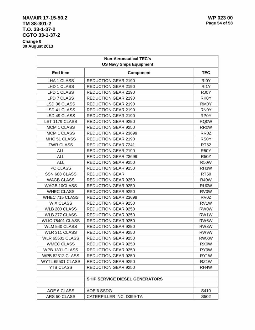
NAVAIR 17-15-50.2 TM 38-301-2 T.O. 33-1-37-2 CGTO 33-1-37-2
WP 023 00 Page 54 of 58
Change 0 30 August 2013
Non-Aeronautical TEC’s US Navy Ships Equipment
End Item Component TEC
LHA 1 CLASS REDUCTION GEAR 2190 RI0Y LHD 1 CLASS REDUCTION GEAR 2190 RI1Y LPD 1 CLASS REDUCTION GEAR 2190 RJ0Y LPD 7 CLASS REDUCTION GEAR 2190 RK0Y LSD 36 CLASS REDUCTION GEAR 2190 RM0Y LSD 41 CLASS REDUCTION GEAR 2190 RN0Y LSD 49 CLASS REDUCTION GEAR 2190 RP0Y
LST 1179 CLASS REDUCTION GEAR 9250 RQ0W MCM 1 CLASS REDUCTION GEAR 9250 RR0W MCM 1 CLASS REDUCTION GEAR 23699 RR0Z MHC 51 CLASS REDUCTION GEAR 2190 RS0Y
TWR CLASS REDUCTION GEAR 7241 RT62 ALL REDUCTION GEAR 2190 R50Y ALL REDUCTION GEAR 23699 R50Z ALL REDUCTION GEAR 9250 R50W
PC CLASS REDUCTION GEAR 9250 RH3W SSN 688 CLASS REDUCTION GEAR RT50 WAGB CLASS REDUCTION GEAR 9250 R40W
WAGB 10CLASS REDUCTION GEAR 9250 RU0W WHEC CLASS REDUCTION GEAR 9250 RV0W
WHEC 715 CLASS REDUCTION GEAR 23699 RV0Z WIX CLASS REDUCTION GEAR 9250 RV1W
WLB 200 CLASS REDUCTION GEAR 9250 RW0W WLB 277 CLASS REDUCTION GEAR 9250 RW1W
WLIC 75401 CLASS REDUCTION GEAR 9250 RW6W WLM 540 CLASS REDUCTION GEAR 9250 RW8W WLR 311 CLASS REDUCTION GEAR 9250 RW9W
WLR 65501 CLASS REDUCTION GEAR 9250 RWXW WMEC CLASS REDUCTION GEAR 9250 RX0W
WPB 1301 CLASS REDUCTION GEAR 9250 RY0W WPB 82312 CLASS REDUCTION GEAR 9250 RY1W WYTL 65501 CLASS REDUCTION GEAR 9250 RZ1W
YTB CLASS REDUCTION GEAR 9250 RH4W SHIP SERVICE DIESEL GENERATORS
AOE 6 CLASS AOE 6 SSDG S410 ARS 50 CLASS CATERPILLER INC. D399-TA S502

NAVAIR 17-15-50.2 TM 38-301-2 T.O. 33-1-37-2 CGTO 33-1-37-2
WP 023 00 Page 55 of 58
Change 0 30 August 2013
Non-Aeronautical TEC’s US Navy Ships Equipment
End Item Component TEC
FFG 7 CLASS STEWART & STEVENSON SERVICE 114D001 SG0J LCC 19 CLASS COLTEC INDUSTRIES INC. 6-38D8 1/8 SH13
LCU CLASS LCU SSDG SH20 LHD 1 CLASS LHD1 SSDG SI10 LSD 41 CLASS COLTEC INDUSTRIES INC.38ND8 1/8 SN03
LST 1179 CLASS ALCO PRODUCTS INC. 8-251-E SQ00 MCM CLASS MCM SSDG SR00 TWR CLASS CATERPILLAR INC. 3304 ST62
ALL MISC SSDG S500 PC CLASS PC SSDG SH30
WAGB 10 CLASS ALCO PRODUCTS INC. 8-251-E SU00 WAGB 10 CLASS CATERPILLER INC. D-379 SU02 WHEC 715 CLASS GENERAL MOTORS CORP. 8-645-E2 SV08 WHEC 715 CLASS GENERAL MOTORS CORP. 8-645-E2 SVA8 WHEC 715 CLASS GENERAL MOTORS CORP. 8-645-E2 SVB8 WHEC 715 CLASS GENERAL MOTORS CORP. 8-645-E2 SVC8 WLB 225 CLASS CATERPILLER INC. 3508 SW02 WLB 277 CLASS DETROIT DIESEL CORP. 6V-92 SW11 WLB 297 CLASS DETROIT DIESEL CORP. #6-71 SWA1 WLI 313 CLASS DETROIT DIESEL CORP. #3-71 SW31
WLI 65303 CLASS DETROIT DIESEL CORP. #2-71 SW41 WLIC 298 CLASS DETROIT DIESEL CORP. #3-71 SW51 WLIC 298 CLASS CATERPILLER INC. 3304 SW52 WLIC 800 CLASS DETROIT DIESEL CORP. #4-71 SW71 WLM 540 CLASS DETROIT DIESEL CORP. #6-71 SW81 WLM 540 CLASS CATERPILLER INC.340TA SW82 WLR 311 CLASS DETROIT DIESEL CORP. #4-71 SW91
WLR 65501 CLASS DETROIT DIESEL CORP. #3-71 SWX1 WLR 65501 CLASS CATERPILLER INC. 3304 SWX2 WLR 75401 CLASS DETROIT DIESEL CORP. #3-71 SWY1 WLR 75401 CLASS CATERPILLER INC. 3304 SWY2
WMEC CLASS CATERPILLER INC. 3406BDT SX02 WMEC CLASS CATERPILLER INC. D398B(TA) SXA2
WPB 1301 CLASS CATERPILLER INC. D3304BT SY02 WPB 82333 CLASS CUMMINS ENGINE CO. INC. 4B3.9GM SY14 WTGB 101 CLASS CATERPILLER INC. 3306B SZ02 WTGB 101 CLASS CUMMINS ENGINE CO. INC. 6BTA5.9-M2 SZ04 WTGB 101 CLASS MURPHY MP-24T SZ0K
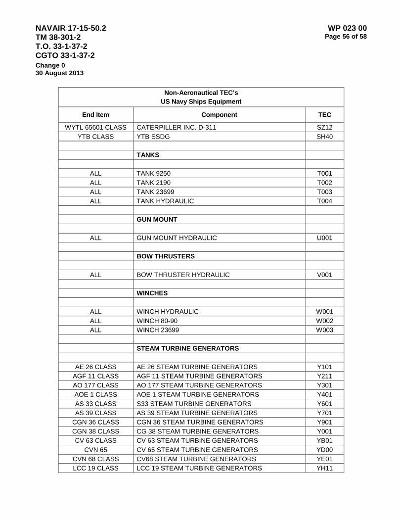
NAVAIR 17-15-50.2 TM 38-301-2 T.O. 33-1-37-2 CGTO 33-1-37-2
WP 023 00 Page 56 of 58
Change 0 30 August 2013
Non-Aeronautical TEC’s US Navy Ships Equipment
End Item Component TEC
WYTL 65601 CLASS CATERPILLER INC. D-311 SZ12 YTB CLASS YTB SSDG SH40
TANKS
ALL TANK 9250 T001 ALL TANK 2190 T002 ALL TANK 23699 T003 ALL TANK HYDRAULIC T004
GUN MOUNT
ALL GUN MOUNT HYDRAULIC U001 BOW THRUSTERS
ALL BOW THRUSTER HYDRAULIC V001 WINCHES
ALL WINCH HYDRAULIC W001 ALL WINCH 80-90 W002 ALL WINCH 23699 W003
STEAM TURBINE GENERATORS
AE 26 CLASS AE 26 STEAM TURBINE GENERATORS Y101 AGF 11 CLASS AGF 11 STEAM TURBINE GENERATORS Y211 AO 177 CLASS AO 177 STEAM TURBINE GENERATORS Y301 AOE 1 CLASS AOE 1 STEAM TURBINE GENERATORS Y401 AS 33 CLASS S33 STEAM TURBINE GENERATORS Y601 AS 39 CLASS AS 39 STEAM TURBINE GENERATORS Y701
CGN 36 CLASS CGN 36 STEAM TURBINE GENERATORS Y901 CGN 38 CLASS CG 38 STEAM TURBINE GENERATORS Y001 CV 63 CLASS CV 63 STEAM TURBINE GENERATORS YB01
CVN 65 CV 65 STEAM TURBINE GENERATORS YD00 CVN 68 CLASS CV68 STEAM TURBINE GENERATORS YE01 LCC 19 CLASS LCC 19 STEAM TURBINE GENERATORS YH11

NAVAIR 17-15-50.2 TM 38-301-2 T.O. 33-1-37-2 CGTO 33-1-37-2
WP 023 00 Page 57 of 58
Change 0 30 August 2013
Non-Aeronautical TEC’s US Navy Ships Equipment
End Item Component TEC
LHA 1 CLASS LHA 1 STEAM TURBINE GENERATORS YI01 LHD 1 CLASS LHD 1 STEAM TURBINE GENERATORS YI11 LPD 1 CLASS LPD1 STEAM TURBINE GENERATORS YJ01 LPD 7 CLASS LPD7 STEAM TURBINE GENERATORS YK01 LSD 36 CLASS LSD 36 STEAM TURBINE GENERATORS YM01
MCS 12 MCS 12 STEAM TURBINE GENERATORS YR11 SSBN 726 CLASS SSBN 726 STEAM TURBINE GENERATORS YT01 SSN 640 CLASS SSN 640 STEAM TURBINE GENERATORS YT31 SSN 671 CLASS SSN 671 STEAM TURBINE GENERATORS YT41 SSN 688 CLASS SSN 688 STEAM TURBINE GENERATORS YT51
AIR SUPPLY SYSTEMS
ALL AIR SUPPLY SYTEM 2190 Z001

NAVAIR 17-15-50.2 TM 38-301-2 T.O. 33-1-37-2 CGTO 33-1-37-2
WP 023 00 Page 58 of 58
Change 0 30 August 2013
This Page Intentionally Left Blank
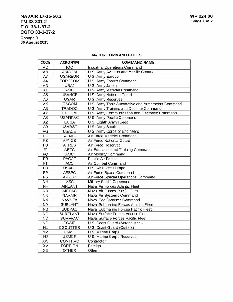
NAVAIR 17-15-50.2 TM 38-301-2 T.O. 33-1-37-2 CGTO 33-1-37-2
WP 024 00 Page 1 of 2
Change 0 30 August 2013
MAJOR COMMAND CODES
CODE ACRONYM COMMAND NAME AC IOC Industrial Operations Command AB AMCOM U.S. Army Aviation and Missile Command A7 USAREUR U.S. Army Europe A4 FORSCOM U.S. Army Forces Command AD USAJ U.S. Army Japan A1 AMC U.S. Army Materiel Command A5 USANGB U.S. Army National Guard A6 USAR U.S. Army Reserves AK TACOM U.S. Army Tank-Automotive and Armaments Command A3 TRADOC U.S. Army Training and Doctrine Command AY CECOM U.S. Army Communication and Electronic Command A8 USARPAC U.S. Army Pacific Command A2 EUSA U.S. Eighth Army Korea A9 USARSO U.S. Army South AG USACE U.S. Army Corps of Engineers FF AFMC Air Force Materiel Command FZ AFNGB Air Force National Guard FU AFRES Air Force Reserves FJ AETC Air Education and Training Command FQ AMC Air Mobility Command FR PACAF Pacific Air Force FT ACC Air Combat Command FD USAFE U.S. Air Force Europe FP AFSPC Air Force Space Command FS AFSOC Air Force Special Operations Command NH MSC Military Sealift Command NF AIRLANT Naval Air Forces Atlantic Fleet NR AIRPAC Naval Air Forces Pacific Fleet NN NAVAIR Naval Air Systems Command NX NAVSEA Naval Sea Systems Command NA SUBLANT Naval Submarine Forces Atlantic Fleet NB SUBPAC Naval Submarine Forces Pacific Fleet NC SURFLANT Naval Surface Forces Atlantic Fleet ND SURFPAC Naval Surface Forces Pacific Fleet NG CGAIR U.S. Coast Guard (Aeronautical) NL CGCUTTER U.S. Coast Guard (Cutters) NM USMC U.S. Marine Corps NJ USMCR U.S. Marine Corps Reserves XW CONTRAC Contractor XV FOREIGN Foreign XE OTHER Other

NAVAIR 17-15-50.2 TM 38-301-2 T.O. 33-1-37-2 CGTO 33-1-37-2
WP 024 00 Page 2 of 2
Change 0 30 August 2013
This Page Intentionally Left Blank