joint oil analysis program manual volume 3
TRANSCRIPT

(NAVY) NAVAIR 17-15-50.3 (ARMY) TM 38-301-3 (AIR FORCE) T.O. 33-1-37-3 (COAST GUARD) TO 33-1-37-3
30 April 2018 Change 1 – 30 June 2019
TECHNICAL MANUAL
JOINT OIL ANALYSIS PROGRAM MANUAL
VOLUME 3
LABORATORY ANALYTICAL METHODOLOGY AND EQUIPMENT CRITERIA (AERONAUTICAL)
This manual supersedes NAVAIR 17-15-50.3 dated 30 August 2013
and incorporates IRACs 39 and 40.
This manual is incomplete without NAVAIR-17-15-50.1, NAVAIR-17-15-50.2 and
NAVAIR-17-15-50.4
DISTRIBUTION STATEMENT A. Approved for public release; distribution is unlimited, determined on 30 August 2013. Other requests for this document shall be referred to Navy Oil Analysis Program, Naval Air Warfare Center, Aircraft Division, Air-4.4.6, 22229 Elmer Road, Patuxent River MD 20670-1534 for all volumes.
DESTRUCTION NOTICE - For unclassified, limited documents, destroy by any method that will prevent disclosure of contents or reconstruction of the document.
Published by direction of Commander, Naval Air Systems Command
under the authority of the Joint Oil Analysis Program Regulation AFI 21-131 (I), AR 700-132 and OPNAVINST 4731.1C.
0817LP1194960

(NAVY) NAVAIR 17-15-50.3 (ARMY) TM 38-301-3 (AIR FORCE) T.O. 33-1-37-3 (COAST GUARD) TO 33-1-37-3
Page A
30 April 2018 Change 1 – 30 June 2019
NUMERICAL INDEX OF EFFECTIVE WORK PACKAGES/PAGES
List of Current Changes Change # Date Change # Date
Original 0 30 April 2018 Change 1 30 June 2019
(Incorporates IRACs 39 and 40)
Only those work packages/pages assigned to the manual are listed in this index. Dispose of the superseded issues of the technical manuals. Superseded classified technical information shall be destroyed in accordance with applicable regulations. The portion of text affected in a changed or revised work package is indicated by change bars in the outer righthand margin.
Total number of pages in Volume 3 of this manual is 450.
Note: the HMWS WP for this manual is located in Volume 2
WP
Number Title Total
Number of Pages
Blank Pages
Change No.
Page A NUMERICAL INDEX OF EFFECTIVE WORK PACKAGES/PAGES A thru K 1 1
TPDR LIST OF TECHNICAL PUBLICATIONS DISCREPANCY REPORTS INCORPORATED
TPDR-1 thru TPDR-2 1 1
001 00 INTRODUCTION AND AERONAUTICAL EQUIPMENT WEAR METAL ANALYTICAL METHODOLOGY 1 THRU 10 1 1
002 00 DECISION MAKING GUIDANCE 1 THRU 2 1 0
003 00 STANDARD LAB RECOMMENDATION CODES - AERONAUTICAL AND AIR FORCE ALC DEPOT DECISION LOGIC 1 THRU 2 1 0
004 00 AIR FORCE LOGISTICS CENTER DEPOT OAP EVALUATION CRITERIA 1 THRU 2 1 0
005 00 ENGINE: J52-P-8B/-8C/-408/-408A/-408B (NAVY) AIRCRAFT: (A-4) (EA-6B) 1 THRU 4 0 0
006 00 ENGINE: J57-P-19/-29/-43/-59 AIRCRAFT: (B-52/C-135) 1 THRU 4 1 0
007 00 ENGINE: J60-P-3/-5 (AIR FORCE) AIRCRAFT: (T-39) 1 THRU 2 0 0
008 00 ENGINE: J60-P-3/-6 AND JT12A (NAVY) AIRCRAFT: (T-2B) (T-39D) (CT-39D) (CT-39G) 1 THRU 2 0 0
009 00 ENGINE: J69-T-25/-25A AIRCRAFT: (T-37) 1 THRU 2 0 0

(NAVY) NAVAIR 17-15-50.3 (ARMY) TM 38-301-3 (AIR FORCE) T.O. 33-1-37-3 (COAST GUARD) TO 33-1-37-3
Page B
30 April 2018 Change 1 – 30 June 2019
WP Number Title
Total Number of
Pages Blank Pages
Change No.
010 00 ENGINE: J75-P-13/-17/-19 AIRCRAFT: (U-2) 1 THRU 2 0 0
011 00 ENGINE: J79-GE-8/-10/-15/-17 AIRCRAFT: (F-4) 1 THRU 4 0 0
012 00 ENGINE: J85-GE-4A AIRCRAFT: (T-2C) 1 THRU 4 1 0
013 00 ENGINE: J85-GE-5/-13 AIRCRAFT: (T-38) (F-5) 1 THRU 4 1 0
014 00 ENGINE: J85-GE-21/-21B/-21C (NAVY) AIRCRAFT: (F-5E/F) 1 THRU 4 0 0
015 00 ENGINE: PT-6A-25 (NAVY) AIRCRAFT: (T-34C) 1 THRU 2 0 0
016 00 ENGINE: PT6A-34B AIRCRAFT: (T-44A/C) 1 THRU 2 0 0
017 00 ENGINE: PT6A-68 AIRCRAFT: (T-6A/B) 1 THRU 2 0 0
018 00 ENGINE: T53-L-13B, T53-L-703 (AIR FORCE) AIRCRAFT: (UH-1H, TH-1H) 1 THRU 2 1 0
019 00 ENGINE: T53-L-11/-13/-13B (ARMY) AIRCRAFT: (H -1) (ALL SERIES) 1 THRU 2 0 0
020 00 ENGINE: T55-L-712A/T55-L-714 AIRCRAFT: (CH-47C/D/F, MH-47E/G) 1 THRU 2 0 0
021 00 ENGINE: T56-A-(ALL SERIES) AIRCRAFT: (C-130) (E-2C) (E2-C+) (C-2) (P-3) 1 THRU 4 1 0
022 00 ENGINE: T58-GE-3/-8/-10 AIRCRAFT: (H-1) 1 THRU 2 0 0
023 00 ENGINE: T58-GE-16/-400B/-402 AIRCRAFT: (H-3) (H-46) 1 THRU 2 0 0
024 00 ENGINE: T63-A/-700/-720 (ARMY) AIRCRAFT: (OH-58A/C) 1 THRU 2 0 0
025 00 ENGINE: T64-GE-100/-413/-416/-416A/-416A+/-419 AIRCRAFT: (CH-53D/E) (MH-53E) 1 THRU 4 1 0
026 00 ENGINE: T64-P4D AIRCRAFT: (C-27) 1 THRU 2 1 0
027 00 ENGINE: T74-CP-702 (PT6-A-20/-27/-28/-29/-41/-42/-50) AIRCRAFT: (C-12/C/D) (UV-18) (SDS-30) 1 THRU 2 0 0
028 00 ENGINE: LTS 101-750A-1/B-2 AIRCRAFT: (HH-65A) 1 THRU 2 0 0

(NAVY) NAVAIR 17-15-50.3 (ARMY) TM 38-301-3 (AIR FORCE) T.O. 33-1-37-3 (COAST GUARD) TO 33-1-37-3
Page C
30 April 2018 Change 1 – 30 June 2019
WP Number Title
Total Number of
Pages Blank Pages
Change No.
029 00 ENGINE: T400-CP-400/-401, T400-WV-402 (NAVY) AIRCRAFT: (AH-1J) (UH-1N) (AH-1T) (VH-1N) 1 THRU 2 0 0
030 00 ENGINE: T400-CP-400 (AIR FORCE) AIRCRAFT: UH-1N 1 THRU 2 0 0
031 00 ENGINE: MK529-8X (NASA) AIRCRAFT: G-159 1 THRU 2 1 0
032 00 ENGINE: AE2100D3 (NAVY AND MARINES) AIRCRAFT: KC-130J 1 THRU 2 1 0
033 00 ENGINE: AE1107C AIRCRAFT: MV-22, CV-22 1 THRU 2 1 0
034 00 ENGINE: TF30-P-414A (NAVY) AIRCRAFT: F-14A 1 THRU 2 0 0
035 00 ENGINE: TF33-P-3/-103, TF33-P11A (WP57F) (NASA) AIRCRAFT: B-52 1 THRU 4 1 0
036 00 ENGINE: TF33-PW-102, JT3D-3B AIRCRAFT: C-18, C-135, C-137, (E-8) 1 THRU 4 1 0
037 00 ENGINE: TF33-P-5/-9 AIRCRAFT: C-135, E-8 1 THRU 4 1 0
038 00 ENGINE: TF33-P-7 AIRCRAFT: C-141 1 THRU 4 1 0
039 00 ENGINE: TF33-P-100 AIRCRAFT: E-3A 1 THRU 4 1 0
040 00 ENGINE: TF34-GE-100A (AIR FORCE) AIRCRAFT: A-10 1 THRU 4 0 0
041 00 ENGINE: TF34-GE-400B (NAVY) AIRCRAFT: S-3B 1 THRU 4 0 0
042 00 ENGINE: TF39-GE-1C (AIR FORCE) AIRCRAFT: C-5 1 THRU 4 0 0
043 00 ENGINE: TF41-A-2/-2A/-2B/-2C/-400/-402C/402D (NAVY) AIRCRAFT: A-7A/-7E/-7F/-7H, EA-7L, TA-7C 1 THRU 4 1 0
044 00 ENGINE: JT8D-9A (AIR FORCE) AIRCRAFT: VC-9C, C-9A, T-43A, C-22A/B 1 THRU 2 0 0
045 00 ENGINE: JT8D-9A (NAVY) AIRCRAFT: C-9B, DC-9 1 THRU 4 0 0
046 00 ENGINE: F100-PW-100/-200/-220/-229 (AIR FORCE) AIRCRAFT: F-15, F-16 1 THRU 6 1 0
047 00 ENGINE: F101-GE-102 (AIR FORCE) AIRCRAFT: B-1B 1 THRU 4 0 0

(NAVY) NAVAIR 17-15-50.3 (ARMY) TM 38-301-3 (AIR FORCE) T.O. 33-1-37-3 (COAST GUARD) TO 33-1-37-3
Page D
30 April 2018 Change 1 – 30 June 2019
WP Number Title
Total Number of
Pages Blank Pages
Change No.
048 00 ENGINE: F108-CF-100GE (AIR FORCE) AIRCRAFT: KC-135R 1 THRU 2 0 0
049 00 ENGINE: F110-GE-100 (AIR FORCE) AIRCRAFT: F-16 1 THRU 6 0 0
050 00 ENGINE: F110-GE0-129 (AIR FORCE) AIRCRAFT: F-16 1 THRU 6 0 0
051 00 ENGINE: F110-GE-400 (NAVY) AIRCRAFT: F-14B, F-14D 1 THRU 4 0 0
052 00 ENGINE: F118-GE-100 (AIR FORCE) AIRCRAFT: B-2 1 THRU 4 0 0
053 00 ENGINE: F118-GE-101 (AIR FORCE) AIRCRAFT: U2S 1 THRU 4 0 0
054 00 ENGINE: F119-PW-100A (AIR FORCE) AIRCRAFT: F-22 1 THRU 8 1 0
055 00 ENGINE: F402-RR-406B/-408A/-408B (USMC)) AIRCRAFT: TAV-8B, AV-8B 1 THRU 2 1 0
056 00 ENGINE: F404-GE-400/-402 (NAVY) AIRCRAFT: F/A-18A/B/C/D 1 THRU 2 0 0
057 00 ENGINE: F135-PW-100 / 400 / 600 (AIR FORCE, NAVY) AIRCRAFT: F-35 (F35A CTOL, F-35B STOVL, F35C CV) 1 THRU 4 1 0
058 00 ENGINE: ROLLS-ROYCE LIFTSYSTEM (AIR FORCE, NAVY) AIRCRAFT: F-35 JOINT STRIKE FIGHTER (F-35B STOVL) 1 THRU 2 0 0
059 00 ENGINE: CFM56-2A-2 (NAVY) AIRCRAFT: E-6A 1 THRU 2 0 0
060 00 ENGINE: CF6-50 (AIR FORCE) AIRCRAFT: E-4B 1 THRU 2 0 0
061 00 ENGINE: F404-GE-F1D2 (AIR FORCE) AIRCRAFT: F-117A 1 THRU 2 0 0
062 00 ENGINE: JT15D-5B (AIR FORCE) AIRCRAFT: T-1A 1 THRU 4 1 0
063 00 ENGINE: IO-360-C/D (AIR FORCE) AIRCRAFT: O-2, O-3 1 THRU 4 1 0
064 00 ENGINE: IO/O-470 (ALL SERIES) (AIR FORCE) AIRCRAFT: T-34, O-1, U-18 1 THRU 2 0 0
065 00 ENGINE: O-470-4 (NAVY) AIRCRAFT: T-34B 1 THRU 2 0 0
066 00 ENGINE: O-480 (ARMY) AIRCRAFT: U-4 1 THRU 2 0 0

(NAVY) NAVAIR 17-15-50.3 (ARMY) TM 38-301-3 (AIR FORCE) T.O. 33-1-37-3 (COAST GUARD) TO 33-1-37-3
Page E
30 April 2018 Change 1 – 30 June 2019
WP Number Title
Total Number of
Pages Blank Pages
Change No.
067 00 HUNTER HFE ENGINES (ARMY) INTERPRETATION AND CORRECTIVE ACTION GUIDE 1 THRU 2 0 0
068 00 AH-1W, HH-1N, UH-1N (NAVY, USMC) MAIN GEARBOX 1 THRU 2 1 0
069 00 AH-1W, HH-1N, UH-1N (NAVY, USMC)) 42° INTERMEDIATE GEARBOX 1 THRU 2 1 0
070 00 AH-1W, HH-1N, UH-1N (NAVY, U1SMC) 90° TAIL ROTOR GEARBOX 1 THRU 2 1 0
071 00 AH-1W, UH-1Y, AH-1Z (NAVY, USMC) COMBINING GEARBOX 1 THRU 2 1 0
072 00 UH-1Y, AH-1Z (NAVY, USMC) MAIN ROTOR GEARBOX (TRANSMISSION) 1 THRU 2 1 0
073 00 UH-1Y, AH-1Z (NAVY, USMC) INTERMEDIATE GEARBOX 1 THRU 2 1 0
074 00 UH-1Y, AH-1Z (NAVY, USMC) TAIL ROTOR GEARBOX 1 THRU 2 1 0
075 00 UH-1N (NAVY AND AIR FORCE) T400 COMBINING GEARBOX 1 THRU 2 0 0
076 00 H-1 (ALL SERIES) (ARMY AND AIR FORCE) TRANSMISSION 1 THRU 2 0 0
077 00 H-1 (ALL SERIES) (ARMY AND AIR FORCE) 42° INTERMEDIATE GEARBOX 1 THRU 2 0 0
078 00 H-1 (ALL SERIES) (ARMY AND AIR FORCE) 90° TAIL ROTOR GEARBOX 1 THRU 2 0 0
079 00 SH-2G (NAVY) MAIN GEARBOX 1 THRU 2 0 0
080 00 SH-2G (NAVY) INTERMEDIATE GEARBOX 1 THRU 2 0 0
081 00 SH-2G (NAVY) TAIL ROTOR GEARBOX 1 THRU 2 0 0
082 00 SH-2G (NAVY) COMBINING GEARBOX 1 THRU 2 0 0
083 00 H-3 (NAVY) TRANSMISSION 1 THRU 2 0 0
084 00 H-3 (NAVY) 42° INTERMEDIATE GEARBOX 1 THRU 2 0 0
085 00 H-3 (NAVY) TAIL ROTOR GEARBOX 1 THRU 2 0 0

(NAVY) NAVAIR 17-15-50.3 (ARMY) TM 38-301-3 (AIR FORCE) T.O. 33-1-37-3 (COAST GUARD) TO 33-1-37-3
Page F
30 April 2018 Change 1 – 30 June 2019
WP Number Title
Total Number of
Pages Blank Pages
Change No.
086 00 H-3, VH-3D (NAVY, USMC) MAIN TRANSMISSION 1 THRU 2 0 0
087 00 H-3, VH-3D (NAVY, USMC) 42° INTERMEDIATE GEARBOX 1 THRU 2 0 0
088 00 H-3, VH-3D (NAVY, USMC) TAIL ROTOR GEARBOX 1 THRU 2 0 0
089 00 MH-6H/-6J/-M/-6N, AH-6M (ARMY) MAIN TRANSMISSION 1 THRU 2 1 0
090 00 MH-6H/-6J/-M/-6N, AH-6M (ARMY) 90° TAIL ROTOR GEARBOX 1 THRU 2 1 0
091 00 CH-34C (NAVY) TRANSMISSION 1 THRU 2 0 0
092 00 CH-34C (NAVY) INTERMEDIATE TRANSMISSION 1 THRU 2 0 0
093 00 CH-34C (NAVY) TAIL ROTOR GEARBOX 1 THRU 2 0 0
094 00 H-43 (AIR FORCE) TRANSMISSION 1 THRU 2 0 0
095 00 H-46 (NAVY, USMC)) FORWARD GEARBOX 1 THRU 2 0 0
096 00 H-46 (NAVY, USMC) AFT GEARBOX 1 THRU 2 0 0
097 00 CH-47D/F, MH-47E/G (ARMY) ENGINE MECHANICAL TRANSMISSION 1 THRU 2 0 0
098 00 CH-47D/F MH-47E/G (ARMY) COMBINING TRANSMISSION 1 THRU 2 0 0
099 00 CH-47D/F MH-47DE/G (ARMY) FORWARD TRANSMISSION 1 THRU 2 0 0
100 00 CH-47D/F MH-47E/G (ARMY) AFT TRANSMISSION 1 THRU 2 1 0
101 00 HH-52 (NAVY, USCG) MAIN TRANSMISSION 1 THRU 2 0 0
102 00 HH-52 (NAVY, USCG) INTERMEDIATE GEARBOX 1 THRU 2 0 0
103 00 HH-52 (NAVY, USCG) TAIL ROTOR GEARBOX 1 THRU 2 0 0
104 00 CH-53E, MH-53E (NAVY, USMC) MAIN GEARBOX 1 THRU 2 0 1

(NAVY) NAVAIR 17-15-50.3 (ARMY) TM 38-301-3 (AIR FORCE) T.O. 33-1-37-3 (COAST GUARD) TO 33-1-37-3
Page G
30 April 2018 Change 1 – 30 June 2019
WP Number Title
Total Number of
Pages Blank Pages
Change No.
105 00 CH-53E, MH-53E (NAVY, USMC) INTERMEDIATE GEARBOX 1 THRU 2 0 1
106 00 CH-53E, MH-53E (NAVY, USMC) ACCESSORY GEARBOX 1 THRU 2 0 1
107 00 CH-53E, MH-53E (NAVY, USMC) NOSE GEARBOX 1 THRU 2 0 1
108 00 CH-53E, MH-53E (NAVY, USMC) TAIL ROTOR GEARBOX 1 THRU 4 1 1
109 00 H-53 (AIR FORCE) TRANSMISSION 1 THRU 2 1 0
110 00 H-57 (NAVY) MAIN GEARBOX 1 THRU 2 1 0
111 00 H-57 (NAVY) TAIL ROTOR GEARBOX 1 THRU 2 1 0
112 00 OH-58A/C (ARMY) TRANSMISSION 1 THRU 2 0 0
113 00 OH-58A/C (ARMY) 90° TAIL ROTOR GEARBOX 1 THRU 2 0 0
114 00 UH60A, EH-60A, HH-60A (ARMY) MAIN TRANSMISSION 1 THRU 2 0 0
115 00 UH-60L, UH-60M, EH-60L, (ARMY) HH-60L, MH-60L, MH-60K, MH-60M MAIN TRANSMISSION (3 MICRON FILTER)
1 THRU 2 0 0
116 00
UH-60A, UH-60L, UH-60M, EH-60A, EH-60L, HH-60A, HH-60L, MH-60K, MH-60L, MH-60M , BLACK HAWK, (ARMY) TAIL ROTOR GEARBOX
1 THRU 12 0 0
117 00 UH-60A, UH-60L, UH-60M, EH-60A, EH-60L, HH-60A, HH-60L, MH-60K, MH-60L, MH-60M, BLACK HAWK (ARMY) INTERMEDIATE GEARBOX
1 THRU 6 0 0
118 00 H-60, (NAVY, USMC, USCG SERIES) MAIN TRANSMISSION
1 THRU 4 1 1
119 00 H-60 (NAVY, USMC, USCG) INTERMEDIATE GEARBOX 1 THRU 8 1 1
120 00 H-60 (NAVY, USMC, USCG) TAIL ROTOR GEARBOX 1 THRU 8 0 1
121 00 VH-60N (NAVY, USMC) TAIL GEARBOX 1 THRU 10 0 0
(NAVY) NAVAIR 17-15-50.3 (ARMY) TM 38-301-3 (AIR FORCE) T.O. 33-1-37-3 (COAST GUARD) TO 33-1-37-3
Page H
30 April 2018 Change 1 – 30 June 2019
WP Number Title
Total Number of
Pages Blank Pages
Change No.
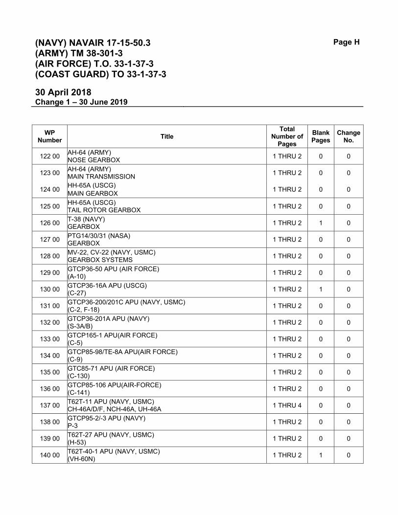
122 00 AH-64 (ARMY) NOSE GEARBOX 1 THRU 2 0 0
123 00 AH-64 (ARMY) MAIN TRANSMISSION 1 THRU 2 0 0
124 00 HH-65A (USCG) MAIN GEARBOX 1 THRU 2 0 0
125 00 HH-65A (USCG) TAIL ROTOR GEARBOX 1 THRU 2 0 0
126 00 T-38 (NAVY) GEARBOX 1 THRU 2 1 0
127 00 PTG14/30/31 (NASA) GEARBOX 1 THRU 2 0 0
128 00 MV-22, CV-22 (NAVY, USMC) GEARBOX SYSTEMS 1 THRU 2 0 0
129 00 GTCP36-50 APU (AIR FORCE) (A-10) 1 THRU 2 0 0
130 00 GTCP36-16A APU (USCG) (C-27) 1 THRU 2 1 0
131 00 GTCP36-200/201C APU (NAVY, USMC) (C-2, F-18) 1 THRU 2 0 0
132 00 GTCP36-201A APU (NAVY) (S-3A/B) 1 THRU 2 0 0
133 00 GTCP165-1 APU(AIR FORCE) (C-5) 1 THRU 2 0 0
134 00 GTCP85-98/TE-8A APU(AIR FORCE) (C-9) 1 THRU 2 0 0
135 00 GTC85-71 APU (AIR FORCE) (C-130) 1 THRU 2 0 0
136 00 GTCP85-106 APU(AIR-FORCE) (C-141) 1 THRU 2 0 0
137 00 T62T-11 APU (NAVY, USMC) CH-46A/D/F, NCH-46A, UH-46A 1 THRU 4 0 0
138 00 GTCP95-2/-3 APU (NAVY) P-3 1 THRU 2 0 0
139 00 T62T-27 APU (NAVY, USMC) (H-53) 1 THRU 2 0 0
140 00 T62T-40-1 APU (NAVY, USMC) (VH-60N) 1 THRU 2 1 0

(NAVY) NAVAIR 17-15-50.3 (ARMY) TM 38-301-3 (AIR FORCE) T.O. 33-1-37-3 (COAST GUARD) TO 33-1-37-3
Page I
30 April 2018 Change 1 – 30 June 2019
WP Number Title
Total Number of
Pages Blank Pages
Change No.
141 00 GTC85 (NAVY) GROUND SUPPORT EQUIPMENT 1 THRU 2 0 0
142 00 GTC85-180 (AIR FORCE) (M32A-60A) 1 THRU 2 0 0
143 00 GTCP85-397 (AIR FORCE) (M32A-60) 1 THRU 2 0 0
144 00 GTCP100 (NAVY) GROUND SUPPORT EQUIPMENT 1 THRU 2 0 0
145 00 T62T-32 (ARMY) (EMU-30) 1 THRU 2 0 0
146 00 A-4F/M (NAVY) CONSTANT SPEED DRIVE 1 THRU 2 0 0
147 00 EA-6B (NAVY) CONSTANT SPEED DRIVE 1 THRU 2 0 0
148 00 AV-8A, TAV-8A (NAVY, USMC) INTEGRATED DRIVE 1 THRU 2 0 0
149 00 F-14 (NAVY) CONSTANT SPEED DRIVE 1 THRU 2 0 0
150 00 S-3 (NAVY) INTEGRATED DRIVE GENERATOR 1 THRU 2 0 0
151 00 H-1 (ALL SERIES) (ARMY, AIR FORCE) HYDRAULIC SYSTEMS 1 THRU 2 0 0
152 00 CH-47 MH-47 (ALL SERIES) (ARMY) HYDRAULIC SYSTEMS 1 THRU 4 1 0
153 00 OH-58A/C (ARMY) HYDRAULIC SYSTEMS 1 THRU 2 0 0
154 00 CURRENT SERVICE EQUIPMENT NOT ENROLLED IN THE JOAP PROGRAM - NO SPECTROMETRIC SAMPLING REQUIRED
1 THRU 2 1 1
155 00 AVIATION TURBINE ENGINE SERVICING CARTS (ARMY, NAVY, AIR FORCE) 1 THRU 2 0 0
156 00 RR250-C20W (NAVY, USMC) MQ-8B ENGINE 1 THRU 2 0 0
157 00 CH-53K INTERMEDIATE GEARBOX (NAVY, USMC) 1 THRU 2 1 0
158 00 CH-53K TAIL ROTOR GEARBOX (NAVY, USMC) 1 THRU 2 1 0

(NAVY) NAVAIR 17-15-50.3 (ARMY) TM 38-301-3 (AIR FORCE) T.O. 33-1-37-3 (COAST GUARD) TO 33-1-37-3
Page J (Page K Blank)
30 April 2018 Change 1 – 30 June 2019
WP Number Title
Total Number of
Pages Blank Pages
Change No.
159 00 CH-53K MAIN GEARBOX (NAVY, USMC) 1 THRU 2 1 0
160 00 CH-53K NOSE GEARBOX (NAVY, USMC) 1 THRU 2 1 0

(NAVY) NAVAIR 17-15-50.3 (ARMY) TM 38-301-3 (AIR FORCE) T.O. 33-1-37-3 (COAST GUARD) TO 33-1-37-3
Page K (Page K Blank)
30 April 2018 Change 1 – 30 June 2019
This Page Intentionally Left Blank

(NAVY) NAVAIR 17-15-50.3 (ARMY) TM 38-301-3 (AIR FORCE) T.O. 33-1-37-3 (COAST GUARD) TO 33-1-37-3
TPDR-1 (TPDR-2 Blank)
30 April 2018 Change 1 – 30 June 2019
NAVAL AIR SYSTEMS COMMAND TECHNICAL MANUAL PROGRAM LIST OF TECHNICAL PUBLICATIONS DEFICIENCY REPORTS INCORPORATED
1. The TPDRs listed below have been incorporated in this issue.
Activity Report Control Number Location
FLTREADCEN EAST CHERRY POINT NC//JETT//
N65923-18-3056 Cherry Point NC Engineering
FLTREADCEN EAST CHERRY POINT NC//MMHISST//
N65923-18-3674 Cherry Point NC Engineering
FLTREADCEN EAST CHERRY POINT NC//JETT//
N65923-18-3833 Cherry Point NC Engineering
FLTREADCEN EAST CHERRY POINT NC//4.4.2.4//
N65923-18-4013 Cherry Point NC Engineering
FLTREADCEN EAST CHERRY POINT NC//MQ-8FST//
N65923-19-1412 Cherry Point NC Engineering

(NAVY) NAVAIR 17-15-50.3 (ARMY) TM 38-301-3 (AIR FORCE) T.O. 33-1-37-3 (COAST GUARD) TO 33-1-37-3
TPDR-2 (TPDR-2 Blank)
30 April 2018 Change 1 – 30 June 2019
This Page Intentionally Left Blank

NAVAIR 17-15-50.3 TM 38-301-3 T.O. 33-1-37-3 CGTO 33-1-37-3
WP 001 00 Page 1 of 10
Change 1 – 30 June 2019
INTRODUCTION AND AERONAUTICAL EQUIPMENT WEAR METAL ANALYTICAL METHODOLOGY
Table of Contents
Page 1. PURPOSE OF THE MANUAL ........................................................................................................................... 1 2. METHODOLOGY .............................................................................................................................................. 1 3. EVALUATING SAMPLE RESULTS ................................................................................................................... 3 4. SPECIAL INSTRUCTIONS ................................................................................................................................ 5 5. EVALUATING ENGINE/TRANSMISSION AND TEST CELL RESULTS .......................................................... 6 6. USAF/ALC DEPOT OAP EVALUATION CRITERIA ......................................................................................... 6 7. FERROGRAPHY (US ARMY) ........................................................................................................................... 7 8. FERROGRAPHIC EVALUATION OF AH-1 HELICOPTER SWASHPLATE AND THE SCISSORS
AND SLEVE ASSEMBLY ....................................................................................................................... 8 9. FERROGRAPHY AS A SUPPLEMENTAL OIL ANALYSIS PROCESS ............................................................ 9
1. PURPOSE OF THE MANUAL
a. Purpose. Volume 3 of the Joint Oil Analysis Program (JOAP) Manual presents the methodology for evaluating spectrometric analyses of samples from aeronautical equipment. The methodology enables an evaluator to identify wear metals present in the sample and their probable sources, to judge equipment condition, and to make recommendations which influence maintenance and operational decisions. Following these recommendations can enhance safety and equipment reliability and contribute to more effective and economic maintenance practices.
b. Applicability. The provisions of this manual apply to all activities of the Departments of the Army, Navy, and the Air Force participating in the JOAP and to laboratories operating under contract or mutual assistance agreements to provide Department of Defense JOAP support.
c. Manual Change Procedures. Detailed procedures for manual changes are contained in Volume 1.
2. METHODOLOGY. The JOAP aeronautical wear metal analytical methodology encompasses the interpretation of used oil sample analysis results, assessment of equipment condition based on the analysis results, diagnosis of the probable source(s) of the wear metal(s), and the issuance of accurate and effective equipment maintenance and/or operational recommendations to the operating activity. This methodology has the potential to standardize evaluator responses and to result in more accurate evaluation criteria and laboratory recommendations.
a. The aeronautical equipment wear metal analytical methodology uses three separate but interrelated sets of tables:

NAVAIR 17-15-50.3 TM 38-301-3 T.O. 33-1-37-3 CGTO 33-1-37-3
WP 001 00 Page 2 of 10
Change 1 – 30 June 2019
(1) Wear Metal Evaluation Criteria Tables are contained in Volume 3 Work Packages which are specific to Type Equipment and End Item. These tables provide wear metal range and trend values which relate the oil sample wear metal concentration to the expected condition of the equipment and/or the oil condition.
(2) Supplemental Diagnostic Guidance Tables. Many Volume 3 Work Packages also contain supplemental diagnostic guidance tables which provide additional wear metal diagnostic guidance for each type of equipment being evaluated to assist in identifying the most probable failing part of the equipment (source of the wear metal) when wear metals are present, singly or in combinations, at other than normal concentrations in the sample or when an abnormal trend is evident. Boxes are placed around elements that will be the primary indicators of a particular failing component.
(3) Decision Making Guidance Table (JOAP Volume 3, WP 002 00) which provides guidelines for the evaluator concerning appropriate recommendations that should be issued after the sample is analyzed.
(4) Volume 3, WP 154 00 contains a list of current service equipment not enrolled in the JOAP program for routine sampling and analysis.
b. Normally, separate Evaluation Criteria and Diagnostic Guidance Tables are provided for each type of equipment, but some tables are combined for different series engines on the same or similar end items. Separate tables are usually required because of differences in the normal sampling intervals, equipment operating characteristics, mission profiles and observed operating times required for wear metal concentrations to progress from normal to abnormal. These characteristics were combined to produce data used to establish wear metal ranges and trends. When possible, information compiled from JOAP-detected failures was used to establish the abnormal wear metal concentration. When this was not possible, the abnormal wear metal concentration was established using accepted statistical methods. The concentration ranges and trend values are continually analyzed and adjusted as required, using historical information, engineering reviews, and equipment teardown results. The sampling intervals, wear metal range limits, and trend values were established to reduce the possibility that the wear metal concentration may go from normal to abnormal without a sample being taken. The concept is one of increased surveillance by more frequent sampling as the wear concentrations increase. Information is provided on abnormal trend values because rapid metal-wear increases, even at low concentrations and within acceptable range limits, may be indicators of impending failure. Activities identifying a requirement to modify these tables for specific equipment should contact the cognizant engineering authority for the equipment involved.
c. If the necessity for making a maintenance recommendation is established, the Supplemental Diagnostic Guidance Tables may then be used to pinpoint possible problem areas and to help identify a specific recommendation. In many cases it is possible to give maintenance personnel an indication of what components in the equipment are wearing abnormally, based on the wear metals being produced.
d. The Decision Making Guide (JOAP Volume 3, WP 002 00) provides a logical sequence of action for the evaluator to follow in determining appropriate laboratory recommendations during the evaluation process. This table is structured so that a laboratory recommendation may be derived from a comparison of the latest oil sample analysis with the analysis of the previous sample with consideration of the trend as a factor. JOAP Volume 3, WP 002 00 is intended for use as a guide for the evaluator. When making a final determination of the appropriate recommendation, the evaluator must consider all the factors involved in the evaluation process. A recommendation for maintenance action is normally considered only after a special sample confirming the previous analysis. However, the evaluator may desire to issue a "do not

NAVAIR 17-15-50.3 TM 38-301-3 T.O. 33-1-37-3 CGTO 33-1-37-3
WP 001 00 Page 3 of 10
Change 1 – 30 June 2019
fly, do not operate" recommendation following an abnormal routine sample pending an evaluation of the special sample if the circumstances warrant such a recommendation. The laboratory recommendation codes in JOAP Volume 3, WP 002 00 are defined in JOAP Volume 3, WP 003 00 and are standard throughout the JOAP for aeronautical equipment. A recommendation code that is the most appropriate for the situation shall be assigned. However, the descriptive text accompanying the recommendation code may be modified to fit the situation, provided the basic definition of the code selected remains unchanged.
e. Sampling frequency is directly related to the probability of detecting impending failure which is, in turn, related to the rapidity of the failure mode. Although oil analysis is intended to provide a high probability of detection of impending failure, a reduced probability of detection may be tolerated in some cases for equipment with built-in redundancy such as multi-engined aircraft, or for systems with low safety risks associated with equipment malfunction or failure, such as aircraft auxiliary power units. Normal sampling frequency requirements, however, are determined by higher authority within each service, are mandatory, and are not subject to modification by laboratory or operating activities without official direction. Laboratories may, however, recommend increased sampling frequency for special samples when analysis results indicate the need for closer equipment monitoring on a temporary basis.
3. EVALUATING SAMPLE RESULTS.
a. Sample results shall be recorded to the tenths decimal place, not rounded to the whole number. It is recommended that labs utilize the RS 232 cable to automatically transfer spectrometer data to the OAP.EX.exe software to meet this requirement.
b. Fully automated laboratories will receive a computer-generated recommendation based on limits entered in the computer program. Although these limits are statistically correct, the computer-generated recommendation is considered as a guide and is not binding upon the evaluator. Evaluator experience and judgment are extremely important factors in determining an effective recommendation since the evaluator may use additional information not contained in the computer statistical program in order to arrive at a more accurate decision for a particular set of circumstances. The following procedure will be used by the evaluator in evaluating sample results:
NOTE
Investigate missing or unusual oil servicing records (such as no oil addition, or excessive oil addition) as these records are an important part of the sample evaluation process.
c. Determine the range for each critical wear metal concentration in the sample result from the appropriate engine/component wear metal Evaluation Criteria Table in Volume 3, WP 005 00 through WP 153 00. Critical wear metals (elements) which require oil analysis monitoring for the particular equipment have numerical criteria provided in the applicable equipment wear metal Evaluation Criteria Table. Data on the average concentration of other elements (listed below the table) are provided for information purposes. However, if unusual concentrations of these non-critical elements are found, they may also be used as a basis for maintenance recommendations or resampling requests.
d. Compare the wear metal concentration levels of the current sample with the levels of the previous sample to determine if changes are occurring which indicate developing or impending equipment problems. When evaluating a new or rebuilt engine, gearbox or component, you will not have previous sample data

NAVAIR 17-15-50.3 TM 38-301-3 T.O. 33-1-37-3 CGTO 33-1-37-3
WP 001 00 Page 4 of 10
Change 1 – 30 June 2019
for comparison. In this situation you will not be able to assess the trend but should simply assess the sample by comparing the results to the other limits found in the specific component’s guidance table.
e. Determine the wear metal trend between the last sample and the current sample and compare with the trend limit listed in the Evaluation Criteria Table. Most abnormal increases will usually be readily apparent. The trend limits in the tables are based on the wear metal concentration increase over a period of 10 equipment operating hours. Most intervals between samples will not be exactly 10 hours; therefore, a conversion must be made for approximate comparison purposes. A trend comparison may be made by dividing the wear metal increase between samples by the operating hours between samples and then multiplying the result by 10. For example: an increase of 2 ppm in 2 hours is roughly equivalent to a 10 ppm increase in 10 hours; and a 15 ppm increase over 25 hours is roughly equivalent to a 6 ppm increase in 10 hours. Trend values for 10 hours are calculated as follows:
A - B x 10 = trend value for 10 hours C - D A = ppm this sample B = ppm last sample C = operating hours this sample D = operating hours last sample
NOTE
The formula shown above for calculating trends is a quick way to determine the trend values. However, trends calculated using this formula for samples taken very frequently (less than 5 operating hours between samples) may be much less accurate and reliable than trends calculated for samples taken less frequently (more than 5 hours between samples). This possibility of error is due to spectrometer allowable tolerances and also to the possibility of a variance in the rate of wear metal production over a period of time. The calculated trends will be very helpful information in the evaluation process, but if samples taken more frequently, such as after each flight, once each flying day, etc. are being evaluated, the calculated trends are not considered accurate for use as equipment acceptable/not acceptable criteria. If the Abnormal Trend is listed as an asterisk (*), the value is too low to be determined.
f. Trend values included in the Evaluation Criteria Tables are intended as guidelines for the evaluator. There are many other factors that must be evaluated to determine actual equipment condition and whether laboratory recommendations to the customer are required. Generally, trends will fall into one of the following categories:
(1) Level (little or no change). Considered normal.
(2) Slightly to moderately increasing or decreasing. Usually considered normal because of spectrometer tolerances, sampling differences, and oil usage/addition factors.
(3) Sharply increasing or decreasing within trend limits. Usually indicative of problems. A sudden increase may indicate the start of an equipment problem, while a sudden decrease may indicate defective sampling procedures, oil addition or change without documentation, or sample identification problems. Recommend verification samples and/or decreased sampling interval for sharp increases, and investigate sampling procedures or undocumented oil addition for sharp decreases.

NAVAIR 17-15-50.3 TM 38-301-3 T.O. 33-1-37-3 CGTO 33-1-37-3
WP 001 00 Page 5 of 10
Change 1 – 30 June 2019
(4) Erratic increases and decreases of trend level. Usually indicates a problem in sampling procedure, (oil addition or change without documentation, sample identification, etc.), and should trigger a request to review activity sampling procedures and submit a monitored verification sample.
(5) Increases exceeding trend limits. Generally indicative of equipment problems. Consult Decision Making Guide and review equipment history. This normally results in a resample request and/or maintenance action recommendation.
NOTE
The above categories are subjective since no limiting increase or decrease point value within the trend limits may be assigned. Categorization of the severity of increases or decreases must be determined by each evaluator after considering all factors involved. The above listing is not considered complete but is provided to show that trend variances, even while still within limits, should be monitored to detect impending problems prior to development of component/system failures, whether action recommendations to operating activities are required or not.
g. Determine the appropriate recommendation using the Decision Making Guide. The majority of sample results will be normal, with the appropriate recommendation code of A. If a recommendation for maintenance action is indicated by the Decision Making Guide, the Supplemental Diagnostic Guidance Table should be reviewed. These tables may provide additional maintenance information concerning likely problem areas that may warrant inclusion in the laboratory recommendation/ maintenance advisory notification to the operating activity.
h. The above procedure can serve as a step-by-step operational guide for evaluator personnel with limited experience, while retaining considerable flexibility for use by an experienced evaluator who can readily take into account the many factors which influence evaluations and recommendations. The judgment and experience of the evaluator are an important part of the evaluation process and should not be subordinated by numerical data when unusual circumstances exist. In many cases, the Decision Making Guide provides options concerning specific recommendations to be issued by the evaluator after considering all information, time since overhaul, time since oil change, past component history, critical element(s), etc. Normally these optional recommendation codes will be sufficient, but in some cases the evaluator may use recommendations not listed as applicable, based upon a thorough evaluation of the circumstances.
NOTE
The wear metal ranges and trend criteria shown in Volume 3, WP 005 00 through WP 153 00 are intended as guidelines to represent normal situations and average equipment oil system condition as related to a numerical value. There will always be exceptions to the average situation, and it is in these cases particularly that the evaluator's experience and judgment must be carefully applied. Some equipment may be candidates for removal before the guidelines are exceeded, such as those with rapid, sharp increases in wear metal levels still within guidelines but accompanied by reported equipment symptoms/malfunctions indicative of internal problems. Conversely, other equipment may be candidates for continued operation when analysis guidelines are exceeded, such as steady, slow, increases in concentration levels that eventually exceed guidelines listed, but are within normal trends and there are no

NAVAIR 17-15-50.3 TM 38-301-3 T.O. 33-1-37-3 CGTO 33-1-37-3
WP 001 00 Page 6 of 10
Change 1 – 30 June 2019
other equipment operational data that indicates problems. However, in this situation the equipment would normally be sampled more frequently in order to minimize the possibility of missing an impending failure. Evaluators perceiving unusual situations such as these should contact the controlling/cognizant engineering authority for the specific equipment for guidance.
4. SPECIAL INSTRUCTIONS
a. Constant Speed Drive Units. Constant Speed Drives (CSDs) are not field repairable and must be returned to depot for overhaul. Every precaution must be taken to assure that no serviceable CSDs are removed from service due solely to decisions resulting from high spectrometric wear metal indications. All physical and functional inspections authorized must be used in conjunction with JOAP spectrometric analysis to ascertain that the CSD in question is in fact malfunctioning or is producing visible gross metal to an extent beyond acceptable limits before removal from service is recommended.
b. Helicopter Gearboxes and Transmissions. Under certain conditions the provisions of JOAP Volume 3, WP 002 00, Decision Making Guidance, may not fully apply. Water in helicopter gearboxes and transmissions may cause high wear metal indications (normally either high iron and copper or high iron, copper, magnesium, and aluminum as a result of internal component corrosion). When high wear metal readings of these elements are obtained, the samples should be examined for water content. If high or abnormal wear metals are detected and/or the water content of the oil is excessive (normally over 1000 PPM or 0.10%), the laboratory recommendation should be to drain the gearbox/transmission (and flush if applicable), re-service with new oil, perform serviceability check in accordance with applicable maintenance manuals, and to submit special oil samples both after serviceability check and after a specified number of flight hours both wear metal and water content analysis. Detailed instructions for evaluating a particular gearbox/transmission are included in the applicable Supplemental Diagnostic Guidance Tables for the specific equipment.
5. EVALUATING ENGINE / TRANSMISSION TEST CELL RESULTS. The information contained in the tables of this manual are not fully applicable to equipment oil samples taken during test cell operational testing following equipment overhaul due to (1) the overhaul process itself and the different rate of wear metal production of newly overhauled engines and transmissions, (2) the brief duration of engine run time and the impossibility of correlating results with trend tables, and (3) the differences between type equipment oil supply during test cell operation (i.e., some engines, as configured for test cell operation, do not include a complete oil system and an external oil supply is required).
a. Certain similarities do exist in determining acceptable wear metal levels and production rates for both test cell and operational engines. Any engine/transmission that exceeds the normal wear metal limit specified in the applicable Evaluation Criteria tables of this manual should be examined to determine the source of the wear metal. However, wear metal levels within the normal range as specified in this manual may also be judged as excessive for test cell purposes at the discretion of the cognizant/controlling engineering authority for the particular equipment. Since the time between oil samples is normally too brief to be useable as a trend in accordance with the Evaluation Criteria Tables of this manual, acceptable and unacceptable trend limits shall be as established by the cognizant/controlling engineering authority for the equipment involved.
b. Engines/transmissions subjected to repair/minor repair in which the oil system remained intact and no repair was accomplished that would affect the oil system wear metal generating pattern, may be

NAVAIR 17-15-50.3 TM 38-301-3 T.O. 33-1-37-3 CGTO 33-1-37-3
WP 001 00 Page 7 of 10
Change 1 – 30 June 2019
evaluated using the evaluation criteria of this manual despite the fact that trend values cannot normally be determined due to the brevity of the test cell operational run. Engines/transmissions in this category are normally subject to post-repair ground run and test flight sampling, and evaluator judgment must again play a large part in determining equipment acceptability for continued operation until sufficient operation time is accumulated to establish a documented equipment trend.
c. Questions concerning equipment test cell wear metal limits and trends should be addressed directly to the cognizant/controlling engineering authority for the particular type/model/series equipment involved.
6. USAF / ALC DEPOT OAP EVALUATION. The USAF Depot OAP evaluation criteria contained in JOAP Volume 3, WP 004 00 are for ALC Depot level use only. When the guidelines of JOAP Volume 3, WP 004 00 are exceeded, the Depot Decision Logic of JOAP Volume 3, WP 003 00, Table 2 should be used.
7. FERROGRAPHY (US ARMY). Ferrography is a fluid analysis technique that can be applied to the analysis of lubricating oils, hydraulic oils, and greases. Ferrography can be used not only to determine the size, shape, and type of wear metal particles being generated within a component, but also to determine the mode of wear (e.g., spalling, cuffing, and rubbing) producing the wear metal particles. Wear metal particles in the size range of 1 to 250 micrometers can be analyzed using ferrography, which makes it an effective supplemental oil analysis procedure. The ferrographic analysis of a lubricant sample is a three step process: (1) Processing the sample through the direct reading (DR) ferrograph, (2) Processing the sample through the analytical ferrograph and preparing the ferrogram, and (3) Examining the ferrogram under the ferroscope. All lubricant samples are mixed with a fixer solution, which aids in the flow of the sample across the substrate and in the development of the ferrogram.
a. The DR ferrograph is an instrument used to measure the concentration of wear metal particles and other debris in lubricants. The sample passes through a precipitator tube placed in a gradient magnetic field. The magnetic material contained in the sample is deposited in the tube and measured at two positions. The readings are indicated as DS (small, 1-2 micrometers) and DL (large, 5 micrometers or larger). This operation takes approximately 5 minutes and provides the information needed to determine if additional analysis is required. Criteria, with thresholds, are established for a component by evaluating numerous samplings of data over a period of time. If an established DR threshold is exceeded, the development of a ferrogram and its examination under the ferroscope is required. The DR ferrograph is not normally used in the analysis of grease samples.
b. The analytical ferrograph is used to prepare a ferrogram. This procedure involves pumping a lubricant sample across a substrate which has a non-wetting barrier applied to one side. The slide is mounted at a slight angle above a magnetic field gradient. Gravitational pull causes the lubricant sample to flow across the slide, and the ferrous particles in the sample are deposited in strings along the surface of the substrate. The largest ferrous particles are deposited at the entry area of the barrier on the substrate. Nonferrous particles are usually contaminated with small amounts of ferrous materials and as a result are attracted to the substrate. Precipitation also causes nonferrous particles to be deposited on the slide. After the lubricant sample is pumped across the substrate, a fixer solution is used to clean the substrate and remove any residual lubricant. After the solution dries, the wear metal particles continue to adhere to the barrier area of the substrate even after being removed from the magnetic field. The ferrogram is then analyzed under the ferroscope.
c. The ferroscope is a bichromatic microscope with filters and a polarizer to direct both transmitted and reflected light onto the ferrogram. The ferroscope can be fitted with a Polaroid camera or a 35 millimeter camera to produce pictures of ferrograms. It can also be fitted with a video monitor for remote viewing of the ferrogram. When examined with bichromatic light under various magnifications, prepared ferrograms

NAVAIR 17-15-50.3 TM 38-301-3 T.O. 33-1-37-3 CGTO 33-1-37-3
WP 001 00 Page 8 of 10
Change 1 – 30 June 2019
disclose relevant information about the wear particles. By observing color and shape and by using various lighting and heating techniques, ferrous and many nonferrous materials can be identified and the mode of wear determined. In order to analyze the ferrogram, the operator requires special training and experience. Once the evaluator is proficient in the operation of the ferrograph system and proficient in evaluation procedures and techniques, he can readily determine the size, shape, type, and amount of wear material. Additional tests such as heat treating and chemical analysis can be conducted to further determine wear metal particle characteristics when viewed under the ferroscope.
d. Modified ferrographic oil analysis procedures are used in the analysis of grease samples. The grease sample is diluted with 14 milliliters of fixer solution to break down the bonding material of the grease. The liquid is then allowed to flow across the substrate by utilizing gravitational flow.
NOTE
The peristaltic pump in the analytical ferrograph is not used.
The substrate is elevated at the entry end to reduce the amount of initial magnetic attraction of the wear particles in the diluted grease and to increase the flow rate across the substrate. The magnetic field aligns the ferrous particles in strings along the slide and the fixer solution is passed across the substrate to remove the residual grease. After drying, the substrate is analyzed under the ferroscope. Evaluation baselines and criteria are developed for each type of component analyzed. Evaluation guideline criteria are provided to Army Oil Analysis Program (AOAP) laboratories in the form of color photographs of samples containing various amounts and types of wear particles. Grease sample ferrograms are compared to these photographs and a subjective evaluation of the wear particle content of the ferrogram is made. A more detailed description of the evaluation process is contained in paragraph 8.
8. FERROGRAPHIC EVALUATION OF AH-1 HELICOPTER SWASHPLATE AND THE SCISSORS AND SLEEVE ASSEMBLY. The ferrographic evaluation of the grease sample is accomplished by comparing the analytical ferrogram with the evaluation guideline photographs furnished to each laboratory under separate cover. The DR ferrograph is not used at this time.
a. Evaluation of the swashplate and scissors and sleeve assemblies can be easily accomplished at or near the entry area using 100x magnification. The most critical types of wear particles found in the evaluation of these components are caused by spalling (contact stress fatigue) formed from the bearing race and balls. In the swashplate, these particles average between 50 and 200 micrometers but can reach 500 micrometers. For the scissors and sleeve assemblies, these particles average between 50 and 150 micrometers, but can be as large as 350 micrometers. A large increase in size and quantity of the spalling particles from one sample to the next is the most dangerous wear situation. A maintenance action may be necessary when the abnormal level of spalling wear (photograph 4) is reached.
b. Rubbing wear is caused by the bearing spinning or fretting and can be very dense in both the swashplate and scissors and sleeve grease samples. Increases in rubbing wear can be tolerated as long as the spalling particles do not increase in size and quantity. An example of this is found in photograph 8. The amount of spalling, marginal to high, makes this a more critical wear situation than that found in photograph 9, which shows abnormal rubbing wear. A removal recommendation could be based on abnormal rubbing wear, but generally the component should be closely monitored for a period of time rather than recommending immediate removal.
NAVAIR 17-15-50.3 TM 38-301-3 T.O. 33-1-37-3 CGTO 33-1-37-3
WP 001 00 Page 9 of 10
Change 1 – 30 June 2019
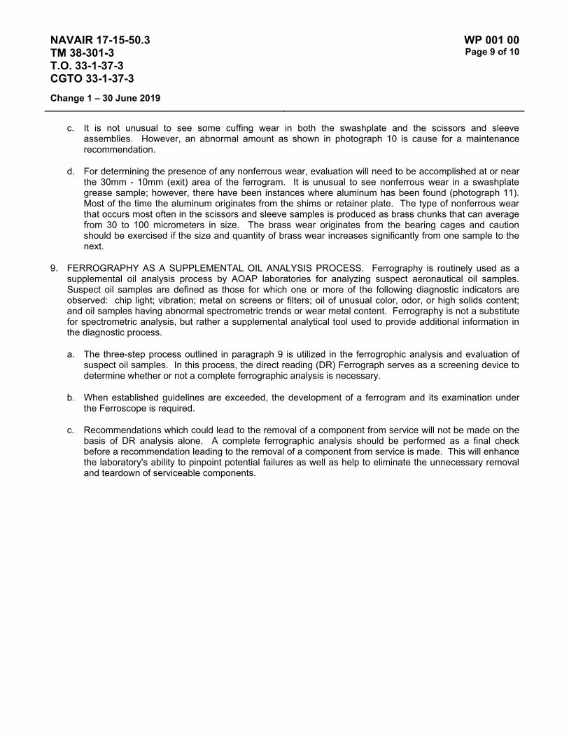
c. It is not unusual to see some cuffing wear in both the swashplate and the scissors and sleeve assemblies. However, an abnormal amount as shown in photograph 10 is cause for a maintenance recommendation.
d. For determining the presence of any nonferrous wear, evaluation will need to be accomplished at or near the 30mm - 10mm (exit) area of the ferrogram. It is unusual to see nonferrous wear in a swashplate grease sample; however, there have been instances where aluminum has been found (photograph 11). Most of the time the aluminum originates from the shims or retainer plate. The type of nonferrous wear that occurs most often in the scissors and sleeve samples is produced as brass chunks that can average from 30 to 100 micrometers in size. The brass wear originates from the bearing cages and caution should be exercised if the size and quantity of brass wear increases significantly from one sample to the next.
9. FERROGRAPHY AS A SUPPLEMENTAL OIL ANALYSIS PROCESS. Ferrography is routinely used as a supplemental oil analysis process by AOAP laboratories for analyzing suspect aeronautical oil samples. Suspect oil samples are defined as those for which one or more of the following diagnostic indicators are observed: chip light; vibration; metal on screens or filters; oil of unusual color, odor, or high solids content; and oil samples having abnormal spectrometric trends or wear metal content. Ferrography is not a substitute for spectrometric analysis, but rather a supplemental analytical tool used to provide additional information in the diagnostic process.
a. The three-step process outlined in paragraph 9 is utilized in the ferrogrophic analysis and evaluation of suspect oil samples. In this process, the direct reading (DR) Ferrograph serves as a screening device to determine whether or not a complete ferrographic analysis is necessary.
b. When established guidelines are exceeded, the development of a ferrogram and its examination under the Ferroscope is required.
c. Recommendations which could lead to the removal of a component from service will not be made on the basis of DR analysis alone. A complete ferrographic analysis should be performed as a final check before a recommendation leading to the removal of a component from service is made. This will enhance the laboratory's ability to pinpoint potential failures as well as help to eliminate the unnecessary removal and teardown of serviceable components.

NAVAIR 17-15-50.3 TM 38-301-3 T.O. 33-1-37-3 CGTO 33-1-37-3
WP 001 00 Page 10 of 10
Change 1 – 30 June 2019
This Page Intentionally Left Blank

NAVAIR 17-15-50.3 TM 38-301-3 T.O. 33-1-37-3 CGTO 33-1-37-3
WP 002 00 Page 1 of 2
30 April 2018
DECISION MAKING GUIDANCE
RECOMMENDATIONS
RANGE THIS SAMPLE
RANGE PREVIOUS SAMPLE
TREND CATEGORY I CATEGORY II
Normal
Normal routine N/A
Normal Abnormal resample or surveillance required surveillance required
Marginal N/A routine or resample required surveillance X 2 required High N/A routine or resample required surveillance X 2 required
Abnormal N/A routine or resample required surveillance X 2 required
Marginal
Normal routine or resample required surveillance required Normal Abnormal resample required surveillance required
Normal routine N/A Marginal Abnormal resample required surveillance required
High N/A routine or resample required surveillance X 2 required
High
Normal resample required surveillance required Normal Abnormal resample required resample or inspection
Normal surveillance required surveillance required Marginal Abnormal resample required resample or inspection
Normal surveillance required surveillance required High Abnormal resample required resample or inspection
Abnormal N/A resample or surveillance required surveillance X 2 required
Abnormal
Normal resample required surveillance required Normal Abnormal resample required resample or inspection
Normal surveillance required surveillance required Marginal Abnormal resample required resample or inspection
Normal surveillance required surveillance required High Abnormal resample required resample or inspection
Normal resample required resample or inspection Abnormal Abnormal inspection required inspection required
Routine samples: A Resample required: B, F, P - use most applicable Surveillance required: C, E - use most applicable. NOTE: (Air Force Labs) Surveillance Code required for
minimum of 3 flights if over 50% of oil is changed, to establish new baseline. Inspection required: H, R, T - use most applicable Self-explanatory: G, J, Q,W, Z NOTE: Two C codes should follow a J code to establish a new baseline. For all routine samples, recommendation in the Category I column will be used. For all laboratory requested special/verification samples, recommendation in Category II will be used.

NAVAIR 17-15-50.3 TM 38-301-3 T.O. 33-1-37-3 CGTO 33-1-37-3
WP 002 00 Page 2 of 2
30 April 2018
This Page Intentionally Left Blank

NAVAIR 17-15-50.3 TM 38-301-3 T.O. 33-1-37-3 CGTO 33-1-37-3
WP 003 00 Page 1 of 2
30 April 2018
STANDARD LAB RECOMMENDATION CODES - AERONAUTICAL AND AIR FORCE ALC DEPOT DECISION LOGIC
1. Refer to Volume 1 WP 005 00 for the Standard Lab Recommendation Codes
2. Air Force ALC Depot Decision Logic Flow Chart
Figure 1 - Air Force ALC Depot Decision Logic Flow Chart

NAVAIR 17-15-50.3 TM 38-301-3 T.O. 33-1-37-3 CGTO 33-1-37-3
WP 003 00 Page 2 of 2
30 April 2018
This Page Intentionally Left Blank

NAVAIR 17-15-50.3 TM 38-301-3 T.O. 33-1-37-3 CGTO 33-1-37-3
WP 004 00 Page 1 of 2
30 April 2018
AIR FORCE LOGISTICS CENTER DEPOT OAP EVALUATION CRITERIA
(Follow ALC Depot Decision Logic When Guidance are Exceeded.)
JOAP ATOMIC EMISSION Fe Ag Al Cr Cu Mg Ni Si Ti
J33 16 4 4 4 5 6 - - - J57-13/21/23 11 3 5 3 3 5 3 - 3 J57-19/29 11 3 5 3 3 5 3 - - J57-43/55/59 11 3 5 3 3 5 3 - 3 J75 9 3 4 4 2 4 - - 2 J79 19 3 3 5 3 7 3 - 3 F100 5 2 2 2 3 3 2 15 3 TF30-P3/7/9 7 2 2 4 3 4 3 - - TF30-P100 7 2 2 4 2 4 2 - 3 TF33-P3/5/9/11A 10 3 5 5 3 5 3 - 3 TF33-P7/7A/100A 10 3 5 5 3 5 3 - 3 TF39 9 3 2 2 5 6 3 25 3 TF41-A-1 12 3 3 4 8 4 3 - 3 TF41-A-2 12 3 3 4 5 4 3 - 3 T56-7/9/15 * 2 1 1 1 1 2 1 5 12 G56-7/9/15 * 2 1 1 1 1 2 1 4 1 T58-3/5 21 4 6 4 6 7 - - - T64 12 3 6 4 5 5 - - - GTC85-70 10 2 3 2 6 5 3 25 5 GTC85-71 8 1 3 2 6 4 3 25 3 GTCP85-108 5 2 2 2 6 2 2 25 2 GTCP85-180 10 3 4 3 6 3 3 25 - GTCP85-397 12 3 3 2 8 4 4 25 4 GTCP165-1 6 2 2 2 3 4 3 25 - T41M-9 50 1 5 4 6 6 2 25 3 NOTE: * Use difference between preliminary sample and acceptance sample. Change oil when Si level exceeds 20
ppm.

NAVAIR 17-15-50.3 TM 38-301-3 T.O. 33-1-37-3 CGTO 33-1-37-3
WP 004 00 Page 2 of 2
30 April 2018
This Page Intentionally Left Blank

NAVAIR 17-15-50.3 TM 38-301-3 T.O. 33-1-37-3 CGTO 33-1-37-3
WP 005 00 Page 1 of 4
30 April 2018
TYPE EQUIPMENT Aircraft Engine
MANUFACTURER Pratt & Whitney
EQUIPMENT/SYSTEM MODEL NUMBER/DESIGNATION
WEAPON SYSTEM PLATFORM(S)
JOAP TYPE EQUIPMENT CODE
J52-P-408 Gbx EA-6B EECB
J52-P-408 Tank EA-6B EECC
J52-P-8B EA-6B EEBB
J52-P-8B A-4 EEBA
J52-P-408 A-4 EECA
LUBRICATING OIL MIL-PRF-23699 (or MIL-PRF-7808 for cold weather ops)
TECHNICAL AUTHORITY NAVAIR J52 Engineering Team
STATUS In Use
Table 1 - JOAP ATOMIC EMISSION ROTRODE LIMITS
Fe Ag Al Cr Cu Mg Ti Si Mo B Zn
Abnormal Trend (PPM Increase in 10 Hrs)
3 1 2 1 2 2 3 5 1
Normal Range 0-5 0 0-2 0-1 0 0 0-1 0-10 0-1 Marginal Range 6-8 * 3-4 * 1 1 2-3 11-12 * High Range 9-11 * 5-6 * 2 2 4-5 13-14 * Abnormal ≥12 ≥1 ≥7 ≥2 ≥3 ≥3 ≥6 ≥15 ≥2 10 10
Fe Nos. 1, 4½, 5, and 6 roller bearing and races Nos. 2, 3, and 4 ball bearing and races Gearbox gears Front and main accessory drive gears
Fe Al Front accessory drive, No. 6 and main gearbox oil pumps

NAVAIR 17-15-50.3 TM 38-301-3 T.O. 33-1-37-3 CGTO 33-1-37-3
WP 005 00 Page 2 of 4
30 April 2018
Fe Ag Cu & Front accessory bearing cages
Si Sn Nos. 4 and 5 scavenge pump bearing cages No. 6 bearing cages
Mg Main accessory drive housing Main gearbox
Cu & Al Fe Main oil pump bushings
Ti & Fe Nos. 1 and 3 bearing hubs
Elevated boron (B) and/or zinc (Zn) concentrations usually indicate contamination with another oil type, primarily MIL-PRF-2104. Recommend resampling and retesting immediately. If new value exceeds 8.0 PPM, run check with D19-0 to ensure proper instrument function. When proper function is confirmed, report both results and suspected contamination with MIL-PRF-2104 to chain of command, maintenance chief, cognizant engineering authority (Army and Navy only), and other personnel as specified by local written procedures. Recommend flushing and retesting of contaminated pre-oilers, carts, or other reservoirs where contamination is found until both B and Zn concentrations fall below 8.0 PPM. Refer to JOAP Manual Volume 2, WP 021 00 for more information. Recommend segregation of confirmed or suspected contaminated stocks, and submit information (batch no., lot no., MIL-PRF, nature of problem, etc.) on such stocks through the Defense supply deficiency reporting system.
J-52 engines may not be operated until spectrometric oil analysis results have been received by the customer; therefore all J-52 samples shall be processed by the JOAP laboratory immediately upon receipt and before other samples previously received. Laboratory personnel shall immediately transmit results to the customer. Laboratory personnel shall log all phone calls, facsimiles and e-mails concerning transmission of results including time of sample receipt, time of results transmission, method of transmission and the name of the point of contact at the customer activity. Refer to the decision making flowchart in Figure 1.
1. If the Fe trend is at or exceeds the abnormal trend limit, AND if ANY ONE of the following elements: Ag, Cr or Mo is at or exceeds the abnormal trend limit issue advice code T, do not fly or operate, recommend engine removal.
2. If the Fe trend and the Ag trend is at or exceeds the abnormal trend limit, issue advice code T, do not fly or operate, recommend engine removal.
3. If the Fe is in the high range or the trend for Fe meets or exceeds the table limit, recommendation shall be code R, do not fly or operate, inspect filter using FDA. If the FDA inspection meets grounding criteria, assign code T, do not fly or operate, recommend engine removal. If the FDA inspection does not meet grounding criteria, place filter on a 25 hour cycle, place JOAP oil sampling on a 5 hour interval until results return to normal.
4. If Cr and/or Mo are abnormal and the Fe is in the normal range, recommend code C, resample after 5 hours, do not change oil. If the resample is abnormal, assign code T, do not fly or operate, recommend engine removal.

NAVAIR 17-15-50.3 TM 38-301-3 T.O. 33-1-37-3 CGTO 33-1-37-3
WP 005 00 Page 3 of 4
30 April 2018
5. If Ag is abnormal, recommend code R, do not fly or operate, inspect filter using FDA. If the FDA inspection meets grounding criteria, assign code T, do not fly or operate, recommend engine removal. If the FDA inspection does not meet grounding criteria, place filter on a 25 hour cycle, place JOAP oil sampling on a 5 hour interval until results return to normal.
6. If Si is abnormal, recommend code J, contamination confirmed, change oil, resample with normal sampling schedule.
NOTES
Increasing trend in Al - inspect gearbox main oil filter and main oil pump housing for scoring.
All bearing journals except titanium may be chrome plated during overhaul.
Oil pump gear journals may be chrome plated during overhaul.

NAVAIR 17-15-50.3 TM 38-301-3 T.O. 33-1-37-3 CGTO 33-1-37-3
WP 005 00 Page 4 of 4
30 April 2018
Figure 1 – Data Evaluation Flow Chart

NAVAIR 17-15-50.3 TM 38-301-3 T.O. 33-1-37-3 CGTO 33-1-37-3
WP 006 00 Page 1 of 4
30 April 2018
TYPE EQUIPMENT Aircraft Engine
MANUFACTURER Pratt & Whitney
EQUIPMENT/SYSTEM MODEL NUMBER/DESIGNATION
WEAPON SYSTEM PLATFORM(S)
JOAP TYPE EQUIPMENT CODE
J57-P-19/-29/-43/-59 B-52 N/A
J57-P-19/-29/-43/-59 C-135 N/A
LUBRICATING OIL MIL-PRF-23699 (or MIL-PRF-7808 for cold weather ops)
TECHNICAL AUTHORITY Air Force
STATUS Engines replaced – WP retained for reference.
Table 1 - JOAP ATOMIC EMISSION ROTRODE LIMITS
Fe Ag Al Cr Cu Mg Ti Si Mo B Zn
* Abnormal Trend (PPM Increase in 10 Hrs)
9 2 3 3 3 4 4
Normal Range 0-6 0 0-2 0 0-1 0-2 0-1 Marginal Range 7-10 1 3 1 2 3-4 2-3 High Range 11-16 2 4 2 3 5 4 Abnormal ≥17 ≥3 ≥5 ≥3 ≥4 ≥6 ≥5 10 10 10 NOTE: * If the calculated PPM trend value is equal to or greater than the trend PPM value limit, the engine has an
abnormal trend.
Elevated boron (B) and/or zinc (Zn) concentrations usually indicate contamination with another oil type, primarily MIL-PRF-2104. Recommend resampling and retesting immediately. If new value exceeds 8.0 PPM, run check with D19-0 to ensure proper instrument function. When proper function is confirmed, report both results and suspected contamination with MIL-PRF-2104 to chain of command, maintenance chief, cognizant engineering authority (Army and Navy only), and other personnel as specified by local written procedures. Recommend flushing and retesting of contaminated pre-oilers, carts, or other reservoirs where contamination is found until both B and Zn concentrations fall below 8.0 PPM. Refer to JOAP Manual Volume 2, WP 021 00 for more information. Recommend segregation of confirmed or suspected contaminated stocks, and submit information (batch no., lot no., MIL-PRF, nature of problem, etc.) on such stocks through the Defense supply deficiency reporting system.

NAVAIR 17-15-50.3 TM 38-301-3 T.O. 33-1-37-3 CGTO 33-1-37-3
WP 006 00 Page 2 of 4
30 April 2018
Elevated silicon (Si) concentration usually indicates contamination with soil, sand, or dust. If aluminum (Al) is also elevated, this suggests the presence of clay or soil. Recommend resampling and retesting immediately. If new value exceeds 8.0 PPM, run check with D19-0 to ensure proper instrument function. When proper function is confirmed, report both results and suspected contamination with soil, sand, or dust to chain of command, maintenance chief, cognizant engineering authority (Army and Navy only), and other personnel as specified by local written procedures. Recommend flushing and retesting of contaminated pre-oilers, carts, or other reservoirs where contamination is found until silicon concentration falls below 8.0 PPM. Refer to JOAP Manual Volume 2, WP 021 00 for more information. Recommend segregation of confirmed or suspected contaminated stocks, and submit information (batch no., lot no., MIL-PRF, nature of problem, etc.) on such stocks through the Defense supply deficiency reporting system.
Cu is the most significant and critical wear metal. When Cu is detected by itself in any amount, maintain close surveillance. Increasing trends in Cu are usually indicative of problem in the Nos. 2, 4, and/or No. 5 bearing. In cases of advanced wear, Cu may be accompanied by increases in Fe. Whenever Fe increases in combination with an increase in Cu, for J57-43/59 engines, first remove the angle drive and inspect the top roller bearing for cage separation, then for all engines, inspect for excessive Nos. 2, 4 and/or 5 bearing wear. Ag may also be detected in advance bearing wear. Increases in Mg usually indicate discrepancy in accessory gearbox (OPAH). When Mg is accompanied by an increase in Fe, the discrepancy is usually in the OPAH bearing area.
When Al increases to abnormal value or is accompanied by a small increase in Fe and, sometimes, Cu, the discrepancy is usually with the main lube pump or scavenge pump. Increases in Cr indicate excessive wear or failure of carbon seal. Increase in Ti indicates Nos. 1, 2, 2½, and/or No. 3 bearing hub wear in J57-43 engine. Increase in Al by itself to abnormal values may indicate a discrepancy in the angle drive coupling. Recommend an inspection to determine whether the angle drive coupling snap ring is out of place or bent in a manner to result in coupling rubbing. Although Pb is not a critical element it may be found in relatively high levels. If Pb only is high and other critical elements, i.e., iron, cooper, etc., are well within limits and Pb exceeds 50 PPM, recommend engine be placed on code “J” (drain and flush). If the Pb levels drop below 50 PPM after the first flight, place the engine on routine sampling intervals.
Ti Nos. 1, 2, 2½ and/or No. 3 bearing hubs (applicable to -43)
Fe Main bearing balls/rollers, races and seals Gearbox gears
Fe Al No. 6 scavenge oil pump (applicable to -43) Gearbox oil pump (applicable to -19/-59)
Fe Al Ag Cu Nos.4, 4½ and 5 scavenge oil pump
& Si Sn
Fe Ag Nos. 2½ and 3 bearing cages (2½ bearing applicable to -43)
Fe Ag Cu Gearbox governor and tach drive bearings

NAVAIR 17-15-50.3 TM 38-301-3 T.O. 33-1-37-3 CGTO 33-1-37-3
WP 006 00 Page 3 of 4
30 April 2018
Fe Ag Cu & Si Sn Gearbox bearing
Fe Mg No. 6 scavenge oil pump (applicable to -19)
Ag Cu & Si Sn Nos. 1, 2, 4, 4½, 5 and 6 bearing cages
Al Mg Gearbox housing and adapter
NOTE
All bearing journals, except those that are titanium, may be chrome plated during rework.

NAVAIR 17-15-50.3 TM 38-301-3 T.O. 33-1-37-3 CGTO 33-1-37-3
WP 006 00 Page 4 of 4
30 April 2018
This Page Intentionally Left Blank

NAVAIR 17-15-50.3 TM 38-301-3 T.O. 33-1-37-3 CGTO 33-1-37-3
WP 007 00 Page 1 of 2
30 April 2018
TYPE EQUIPMENT Aircraft Engine
MANUFACTURER Pratt & Whitney
EQUIPMENT/SYSTEM MODEL NUMBER/DESIGNATION
WEAPON SYSTEM PLATFORM(S)
JOAP TYPE EQUIPMENT CODE
J60-P-3A T-39 EHBA
LUBRICATING OIL MIL-PRF-7808
TECHNICAL AUTHORITY Air Force J60 Engineering Team
STATUS In Use
Table 1 - JOAP ATOMIC EMISSION ROTRODE LIMITS
Fe Ag Al Cr Cu Mg Ni Ti B Si Zn * Abnormal Trend (PPM Increase in 10 Hrs)
7 3 3 3 4 5 3
Normal Range 0-14 0-1 0-3 0-4 0-4 0-10 0-5 Marginal Range 15-21 2-7 4-6 5-7 5-7 11-15 6-7 High Range 22-34 8 7-11 8 8-14 16-24 8-9 Abnormal ≥35 ≥9 ≥12 ≥9 ≥15 ≥25 ≥10 10 10 10 NOTE: * If the calculated PPM trend value is equal to or greater than the trend PPM value limit, the engine has an
abnormal trend.
Elevated boron (B) and/or zinc (Zn) concentrations usually indicate contamination with another oil type, primarily MIL-PRF-2104. Recommend resampling and retesting immediately. If new value exceeds 8.0 PPM, run check with D19-0 to ensure proper instrument function. When proper function is confirmed, report both results and suspected contamination with MIL-PRF-2104 to chain of command, maintenance chief, cognizant engineering authority (Army and Navy only), and other personnel as specified by local written procedures. Recommend flushing and retesting of contaminated pre-oilers, carts, or other reservoirs where contamination is found until both B and Zn concentrations fall below 8.0 PPM. Refer to JOAP Manual Volume 2, WP 021 00 for more information. Recommend segregation of confirmed or suspected contaminated stocks, and submit information (batch no., lot no., MIL-PRF, nature of problem, etc.) on such stocks through the Defense supply deficiency reporting system.
Elevated silicon (Si) concentration usually indicates contamination with soil, sand, or dust. If aluminum (Al) is also elevated, this suggests the presence of clay or soil. Recommend resampling and retesting immediately. If new value exceeds 8.0 PPM, run check with D19-0 to ensure proper instrument function. When proper function is confirmed, report both results and suspected contamination with soil, sand, or dust to chain of command, maintenance chief, cognizant engineering authority (Army and Navy only), and other personnel as specified by local written procedures. Recommend flushing and retesting of contaminated pre-oilers, carts, or other reservoirs

NAVAIR 17-15-50.3 TM 38-301-3 T.O. 33-1-37-3 CGTO 33-1-37-3
WP 007 00 Page 2 of 2
30 April 2018
where contamination is found until silicon concentration falls below 8.0 PPM. Refer to JOAP Manual Volume 2, WP 021 00 for more information. Recommend segregation of confirmed or suspected contaminated stocks, and submit information (batch no., lot no., MIL-PRF, nature of problem, etc.) on such stocks through the Defense supply deficiency reporting system.
When Fe increases in combination with an increase in Mg, the discrepancy is usually with the accessory gear case. When Fe increases in combination with an increase in Cu, the discrepancy may be a main shaft bearing; usually No. 3. High Fe, Cu and Mg in combination usually indicate discrepancy with the tower shaft bearing. Increases in Mg by itself indicate defect in accessory gear case. Fuel contamination of oil indicates rupture of fuel oil cooler.
NOTE
High lead concentrations alone in J60 engine used oil DO NOT warrant engine removal and repair actions. Lead plating on No. 1 bearing, P/N 410787, is source of lead.
Fe Main bearing balls/rollers and races Gearbox gears
Fe Al Pressure and scavenge oil pump
Fe Ag Cu Gearbox bearings
& Si Sn
Ag Cu & Main bearing cages
Si Sn
Al Mg Gearbox housing and adapters
Ti Compressor rotor front hub
OIL CAPACITY AND CONSUMPTION INFORMATION
1. Oil capacity of the engine is 5 quarts. Ref. T.O. 1T-39A-2-1.
2. Allowable oil consumption rate (quantity per time) shall not exceed ¾ pint per hour (Ref T.O. 1T-39A-2-1).
3. Recommended engine oil consumption inspection interval: At 500-hour maintenance inspection or when engine is suspected of excessive oil usage.
4. Action to take if maximum oil consumption rate is exceeded: Identify/correct cause of high oil consumption.

NAVAIR 17-15-50.3 TM 38-301-3 T.O. 33-1-37-3 CGTO 33-1-37-3
WP 008 00 Page 1 of 2
30 April 2018
TYPE EQUIPMENT Aircraft Engine
MANUFACTURER Pratt & Whitney
EQUIPMENT/SYSTEM MODEL NUMBER/DESIGNATION
WEAPON SYSTEM PLATFORM(S)
JOAP TYPE EQUIPMENT CODE
J60-P-3 (NAVY) T-39 EHAA
J60-P-3A (NAVY) T-39 EHBA
JT-12A-8 (NAVY) T-39 KLAA
LUBRICATING OIL MIL-PRF-23699 (or MIL-PRF-7808 for cold weather ops)
TECHNICAL AUTHORITY NAVAIR J60 Engineering Team
STATUS In Use
Table 1 - JOAP ATOMIC EMISSION ROTRODE LIMITS
Fe Ag Al Cr Cu Mg Ti B Si Zn
Abnormal Trend (PPM Increase in 10 Hrs)
6 3 3 3 3 6 3
Normal Range 0-20 0-6 0-8 0-6 0-7 0-18 0-8 Marginal Range 21-25 7 9 7 8 19-22 9 High Range 26-30 8 10-11 8 9-11 23-26 10-11 Abnormal ≥31 ≥9 ≥12 ≥9 ≥12 ≥27 ≥12 10 10 10
Elevated boron (B) and/or zinc (Zn) concentrations usually indicate contamination with another oil type, primarily MIL-PRF-2104. Recommend resampling and retesting immediately. If new value exceeds 8.0 PPM, run check with D19-0 to ensure proper instrument function. When proper function is confirmed, report both results and suspected contamination with MIL-PRF-2104 to chain of command, maintenance chief, cognizant engineering authority (Army and Navy only), and other personnel as specified by local written procedures. Recommend flushing and retesting of contaminated pre-oilers, carts, or other reservoirs where contamination is found until both B and Zn concentrations fall below 8.0 PPM. Refer to JOAP Manual Volume 2, WP 021 00 for more information. Recommend segregation of confirmed or suspected contaminated stocks, and submit information (batch no., lot no., MIL-PRF, nature of problem, etc.) on such stocks through the Defense supply deficiency reporting system.
Elevated silicon (Si) concentration usually indicates contamination with soil, sand, or dust. If aluminum (Al) is also elevated, this suggests the presence of clay or soil. Recommend resampling and retesting immediately. If new value exceeds 8.0 PPM, run check with D19-0 to ensure proper instrument function. When proper function is confirmed, report both results and suspected contamination with soil, sand, or dust to chain of command, maintenance chief, cognizant engineering authority (Army and Navy only), and other personnel as specified by local written procedures. Recommend flushing and retesting of contaminated pre-oilers, carts, or other reservoirs

NAVAIR 17-15-50.3 TM 38-301-3 T.O. 33-1-37-3 CGTO 33-1-37-3
WP 008 00 Page 2 of 2
30 April 2018
where contamination is found until silicon concentration falls below 8.0 PPM. Refer to JOAP Manual Volume 2, WP 021 00 for more information. Recommend segregation of confirmed or suspected contaminated stocks, and submit information (batch no., lot no., MIL-PRF, nature of problem, etc.) on such stocks through the Defense supply deficiency reporting system.
When Fe increases in combination with an increase in Mg, the discrepancy is usually with the accessory gear case. When Fe increases in combination with an increase in Cu, the discrepancy may be a main shaft bearing, usually No. 3. High, Fe, Cu and Mg in combination usually indicates discrepancy with the tower shaft bearing. Increases in Mg by itself indicates defect in accessory gear case. Fuel contamination of oil indicates rupture of fuel oil cooler.
Fe Main bearing balls/rollers and races Gearbox gears
Fe Al Pressure and scavenge oil pump
Fe Ag Cu Gearbox bearings
& Si Sn
Ag Cu & Main bearing cages
Si Sn
Al Mg Gearbox housing and adapters
Ti Compressor rotor front hub

NAVAIR 17-15-50.3 TM 38-301-3 T.O. 33-1-37-3 CGTO 33-1-37-3
WP 009 00 Page 1 of 2
30 April 2018
TYPE EQUIPMENT Aircraft Engine
MANUFACTURER Teledyne CAE
EQUIPMENT/SYSTEM MODEL NUMBER/DESIGNATION
WEAPON SYSTEM PLATFORM(S)
JOAP TYPE EQUIPMENT CODE
J69-T-25/-25A T-37 EKAA
LUBRICATING OIL MIL-PRF-7808
TECHNICAL AUTHORITY Air Force
STATUS Aircraft Retired – WP retained for reference.
Table 1 - JOAP ATOMIC EMISSION ROTRODE LIMITS
Fe Ag Al Cr Cu Mg B Si Zn * Abnormal Trend (PPM Increase in 10 Hrs)*
8 3 4 4 3 4
Normal Range 0-8 0 0-1 0 0-7 0-2 Marginal Range 9-15 1-2 2-3 1-2 8-9 3-8 High Range 16-40 3-9 4-14 3-18 10-11 9-14 Abnormal ≥41 ≥10 ≥15 ≥19 ≥12 ≥15 10 10 10 NOTE: * If the calculated PPM trend value is equal to or greater than the trend PPM value limit, the engine has an
abnormal trend.
Elevated boron (B) and/or zinc (Zn) concentrations usually indicate contamination with another oil type, primarily MIL-PRF-2104. Recommend resampling and retesting immediately. If new value exceeds 8.0 PPM, run check with D19-0 to ensure proper instrument function. When proper function is confirmed, report both results and suspected contamination with MIL-PRF-2104 to chain of command, maintenance chief, cognizant engineering authority (Army and Navy only), and other personnel as specified by local written procedures. Recommend flushing and retesting of contaminated pre-oilers, carts, or other reservoirs where contamination is found until both B and Zn concentrations fall below 8.0 PPM. Refer to JOAP Manual Volume 2, WP 021 00 for more information. Recommend segregation of confirmed or suspected contaminated stocks, and submit information (batch no., lot no., MIL-PRF, nature of problem, etc.) on such stocks through the Defense supply deficiency reporting system.
Elevated silicon (Si) concentration usually indicates contamination with soil, sand, or dust. If aluminum (Al) is also elevated, this suggests the presence of clay or soil. Recommend resampling and retesting immediately. If new value exceeds 8.0 PPM, run check with D19-0 to ensure proper instrument function. When proper function is confirmed, report both results and suspected contamination with soil, sand, or dust to chain of command, maintenance chief, cognizant engineering authority (Army and Navy only), and other personnel as specified by local written procedures. Recommend flushing and retesting of contaminated pre-oilers, carts, or other reservoirs

NAVAIR 17-15-50.3 TM 38-301-3 T.O. 33-1-37-3 CGTO 33-1-37-3
WP 009 00 Page 2 of 2
30 April 2018
where contamination is found until silicon concentration falls below 8.0 PPM. Refer to JOAP Manual Volume 2, WP 021 00 for more information. Recommend segregation of confirmed or suspected contaminated stocks, and submit information (batch no., lot no., MIL-PRF, nature of problem, etc.) on such stocks through the Defense supply deficiency reporting system.
Any T-37 oil sample that flames up in the oil analysis spectrometer will prompt the JOAP lab to place the engine on code T (tear down). Fuel contamination of the oil will be reported to responsible activity when detected. Fe is principal wear metal. Gradual increase in Fe near or to the abnormal value over a long period of time (several hundred flying hours) is sometimes indicative of rotational movement of the No. 2 bearing. This rotational movement, or creep, characteristic is normal and is a design feature of the No. 2 bearing. Rapid increases in Fe are sometimes indicative of accessory drive gear shaft nut backing off because of a sheared tang on the nut lock.
Rapid increases in Al, to or exceeding abnormal value, can sometimes be attributed to improper stack up of the engine resulting in rub of the No. 2 bearing labyrinth seal against the turbine shaft. When Cr approaches the abnormal value, it is a possible indication of wear in the No. 2 bearing housing, or front and rear turbine shaft. Increases in Ag are indicative of bearing wear and are usually in combination with high Fe and Cu. Increases in Cu and Mg individually, or together, are an indication of problem in the accessory case section.
Fe Main bearing balls/rollers and races Starter generator and accessory drive gears Accessory case gears
Fe Al Accessory oil pump
& Cr
Fe Ag Cu Accessory case bearings
& Sn
Cu Sn Starter generator and accessory drive bearing cages
Al Mg Accessory case housing and adapters
OIL CAPACITY AND CONSUMPTION INFORMATION REFERENCE MATERIAL
1. The engine oil capacity is 6 quarts (4.5 usable quarts).
2. The allowable oil consumption rate is 1.5 quarts per hour.
3. Oil consumption inspection interval is after each flight, within 10 minutes of engine shutdown.
4. If maximum allowable oil consumption is exceeded, check lines and seals for leaks.

NAVAIR 17-15-50.3 TM 38-301-3 T.O. 33-1-37-3 CGTO 33-1-37-3
WP 010 00 Page 1 of 2
30 April 2018
TYPE EQUIPMENT Aircraft Engine
MANUFACTURER Pratt & Whitney
EQUIPMENT/SYSTEM MODEL NUMBER/DESIGNATION
WEAPON SYSTEM PLATFORM(S)
JOAP TYPE EQUIPMENT CODE
J75-P-13/-17/-19 U-2 N/A
LUBRICATING OIL MIL-PRF-7808
TECHNICAL AUTHORITY Air Force
STATUS Engine Retired – WP retained for reference.
Table 1 - JOAP ATOMIC EMISSION ROTRODE LIMITS
Fe Ag Al Cr Cu Mg Ti B Si Zn
Abnormal Trend (PPM Increase in 10 Hrs)
9 2 3 2 3 4 2
Normal Range 0-30 0-3 0-8 0-4 0-6 0-12 0-2 Marginal Range 31-37 N/A 9 5 7 13-15 3 High Range 38-44 4 10-11 6 8-9 16-17 4 Abnormal ≥45 ≥5 ≥12 ≥7 ≥10 ≥18 ≥5 10 10 10
Elevated boron (B) and/or zinc (Zn) concentrations usually indicate contamination with another oil type, primarily MIL-PRF-2104. Recommend resampling and retesting immediately. If new value exceeds 8.0 PPM, run check with D19-0 to ensure proper instrument function. When proper function is confirmed, report both results and suspected contamination with MIL-PRF-2104 to chain of command, maintenance chief, cognizant engineering authority (Army and Navy only), and other personnel as specified by local written procedures. Recommend flushing and retesting of contaminated pre-oilers, carts, or other reservoirs where contamination is found until both B and Zn concentrations fall below 8.0 PPM. Refer to JOAP Manual Volume 2, WP 021 00 for more information. Recommend segregation of confirmed or suspected contaminated stocks, and submit information (batch no., lot no., MIL-PRF, nature of problem, etc.) on such stocks through the Defense supply deficiency reporting system.
Elevated silicon (Si) concentration usually indicates contamination with soil, sand, or dust. If aluminum (Al) is also elevated, this suggests the presence of clay or soil. Recommend resampling and retesting immediately. If new value exceeds 8.0 PPM, run check with D19-0 to ensure proper instrument function. When proper function is confirmed, report both results and suspected contamination with soil, sand, or dust to chain of command, maintenance chief, cognizant engineering authority (Army and Navy only), and other personnel as specified by local written procedures. Recommend flushing and retesting of contaminated pre-oilers, carts, or other reservoirs where contamination is found until silicon concentration falls below 8.0 PPM. Refer to JOAP Manual Volume 2, WP 021 00 for more information. Recommend segregation of confirmed or suspected contaminated stocks, and submit information (batch no., lot no., MIL-PRF, nature of problem, etc.) on such stocks through the Defense

NAVAIR 17-15-50.3 TM 38-301-3 T.O. 33-1-37-3 CGTO 33-1-37-3
WP 010 00 Page 2 of 2
30 April 2018
supply deficiency reporting system.
High Fe or Fe in combination with Cu usually indicates bearing trouble, particularly Nos. 3, 4, or 5 bearings. Increase in Mg which may be accompanied with increase in Fe indicates possible discrepancy due to fretting of the bearing liner in the main gearbox. High Al and Fe may indicate defective oil pump. Ti is a significant wear metal. Increases in Ti are indicative of the spacer between Nos. 2, 2½ and 3 bearing turning on the shaft. High Fe together with high Ti indicates discrepancy in the Nos. 2, 2½ and No. 3 bearing area.
NOTE
High Al by itself may be indicative of worn threaded area on oil tank breather tee fitting and is due to movement of fitting.
Fe Main bearing balls/rollers, races, seals and housing Front accessory drive gears Main accessory drive gears and housing Main gearbox gears
Fe Al Front accessory drive oil pump Main gearbox oil pump
Fe Ag No. 3 bearing cages Main accessory drive bearings
Fe Ag Cu & Main gearbox bearings
Si Sn
Ag Cu & Nos. 1, 2, 2½, 4, 4½, 5 and 6 bearings cages
Si Sn
Mg Front accessory drive and main gearbox housing
Ti No. 2 hub shaft between Nos. 2, 2½, and 3 main bearing

NAVAIR 17-15-50.3 TM 38-301-3 T.O. 33-1-37-3 CGTO 33-1-37-3
WP 011 00 Page 1 of 4
30 April 2018
TYPE EQUIPMENT Aircraft Engine
MANUFACTURER General Electric
EQUIPMENT/SYSTEM MODEL NUMBER/DESIGNATION
WEAPON SYSTEM PLATFORM(S)
JOAP TYPE EQUIPMENT CODE
J79-GE-8/-10/-15/-17 F-4 EPEA
LUBRICATING OIL MIL-PRF-7808
TECHNICAL AUTHORITY Air Force
STATUS In Use
Table 1 - JOAP ATOMIC EMISSION ROTRODE LIMITS
Fe Ag Al Cr Cu Mg B Si Zn
Abnormal Trend (PPM Increase in 10 Hrs)
11 2 3 6 5 4
Normal Range 0-29 0-3 0-8 0-10 0-18 0-14 Marginal Range 30-36 4 9 11-12 19-22 15-17 High Range 37-44 5 10-11 13-14 23-27 18-21 Abnormal ≥45 ≥6 ≥12 ≥15 ≥28 ≥22 10 10 10
Elevated boron (B) and/or zinc (Zn) concentrations usually indicate contamination with another oil type, primarily MIL-PRF-2104. Recommend resampling and retesting immediately. If new value exceeds 8.0 PPM, run check with D19-0 to ensure proper instrument function. When proper function is confirmed, report both results and suspected contamination with MIL-PRF-2104 to chain of command, maintenance chief, cognizant engineering authority (Army and Navy only), and other personnel as specified by local written procedures. Recommend flushing and retesting of contaminated pre-oilers, carts, or other reservoirs where contamination is found until both B and Zn concentrations fall below 8.0 PPM. Refer to JOAP Manual Volume 2, WP 021 00 for more information. Recommend segregation of confirmed or suspected contaminated stocks, and submit information (batch no., lot no., MIL-PRF, nature of problem, etc.) on such stocks through the Defense supply deficiency reporting system.

NAVAIR 17-15-50.3 TM 38-301-3 T.O. 33-1-37-3 CGTO 33-1-37-3
WP 011 00 Page 2 of 4
30 April 2018
Elevated silicon (Si) concentration usually indicates contamination with soil, sand, or dust. If aluminum (Al) is also elevated, this suggests the presence of clay or soil. Recommend resampling and retesting immediately. If new value exceeds 8.0 PPM, run check with D19-0 to ensure proper instrument function. When proper function is confirmed, report both results and suspected contamination with soil, sand, or dust to chain of command, maintenance chief, cognizant engineering authority (Army and Navy only), and other personnel as specified by local written procedures. Recommend flushing and retesting of contaminated pre-oilers, carts, or other reservoirs where contamination is found until silicon concentration falls below 8.0 PPM. Refer to JOAP Manual Volume 2, WP 021 00 for more information. Recommend segregation of confirmed or suspected contaminated stocks, and submit information (batch no., lot no., MIL-PRF, nature of problem, etc.) on such stocks through the Defense supply deficiency reporting system.
Caution must be exercised when evaluating this system due to the common oil supply of engine and CSD. When Fe increases by itself or in combination with Cu, recommend transfer gearbox starter drive area be checked for loose nut on drive or for broken carbon seal. Also recommend inspection of the front of transfer gearbox for same problem and inspection of filters including CSD filter. When Cu increases in combination with Fe, but Cu is higher, the problem will usually be in the CSD. High Mg is usually indicative of discrepancy in the gearbox. Any increase in Ag in usually indicative of incipient No. 2 bearing failure and will be accompanied with high Fe with or without increases in Cu.
Fe & Ni Main bearing housings
Fe & Cr Afterburner fuel pump gears and bearings No. 2 bearings, balls and races
Fe & Cr Ni No. 1 bearing rollers, races and carbon seal runners Gearbox gears, shafts and splines
Fe & Cr Al or Ni No. 3 bearing rollers and races
Fe & Cr Cu or Ni Accessory variable nozzle actuator
Fe Cu & Al Si Accessory main lube and hydraulic pump
Fe Cu & Al Ni Accessory scavenge pumps
Fe Cu & Ag Cr Si Gearbox bearings
Fe Cu Mg & Al Constant speed drive
Fe Cu Ag* & Al Cr Sn Pb Ni Si Accessory variable nozzle pump

NAVAIR 17-15-50.3 TM 38-301-3 T.O. 33-1-37-3 CGTO 33-1-37-3
WP 011 00 Page 3 of 4
30 April 2018
*Ag in 1P, 1M and 1N pumps
Fe Cu Al Mg & Cr Ni Variable nozzle control valve
Cu & Ag Fe Si Main bearing cages and afterburner fuel pump bearing cages
Al Mg Gearbox castings
Cr & Fe Ni Main bearing seal races
Caution must be exercised when evaluating this system due to the common oil supply of engine and CSD. When Fe increases by itself or in combination with Cu, recommend transfer gearbox starter drive area be checked for loose nut on drive or for broken carbon seal. Also recommend inspection of the front of transfer gearbox for same problem and inspection of filters including CSD filter. When Cu increases in combination with Fe, but Cu is higher, the problem will usually be in the CSD. Also, increase in Mg and/or in combination with Fe and/or Cu may be caused by CSD's. The CSD should be removed and bench checked to determine if CSD replacement will eliminate the wear metal problems. High Mg is usually indicative of discrepancy in the gearbox.
Any increase in Ag is usually indicative of incipient No. 2 bearing failure and will be accompanied with high Fe with or without increases in Cu. When Fe increases 5 PPM, between consecutive oil samples from J79-15 and J79-17 engines without accompanying increases to other wear metals, it may be indicative of an afterburner fuel pump bearing failure. Check samples should be requested to confirm Fe increases. All unmodified afterburner fuel pumps (Part Number P/N 512D809P8, P9, P11, and P12) will be removed and sent to repairable supply. Fuel pumps with other part numbers may be retained but visually examined for discrepancies.
Fe & Ni Main bearing housings
Fe & Cr Afterburner fuel pump gears and bearings No. 2 bearings, balls and races
Fe & Cr Ni No. 1 bearing rollers, races and carbon seal runners Gearbox gears, shafts and splines
Fe & Cr Al or Ni No. 3 bearing rollers and races
Fe & Cr Cu or Ni Accessory variable nozzle actuator
Fe Cu & Al Si Accessory main lube and hydraulic pump
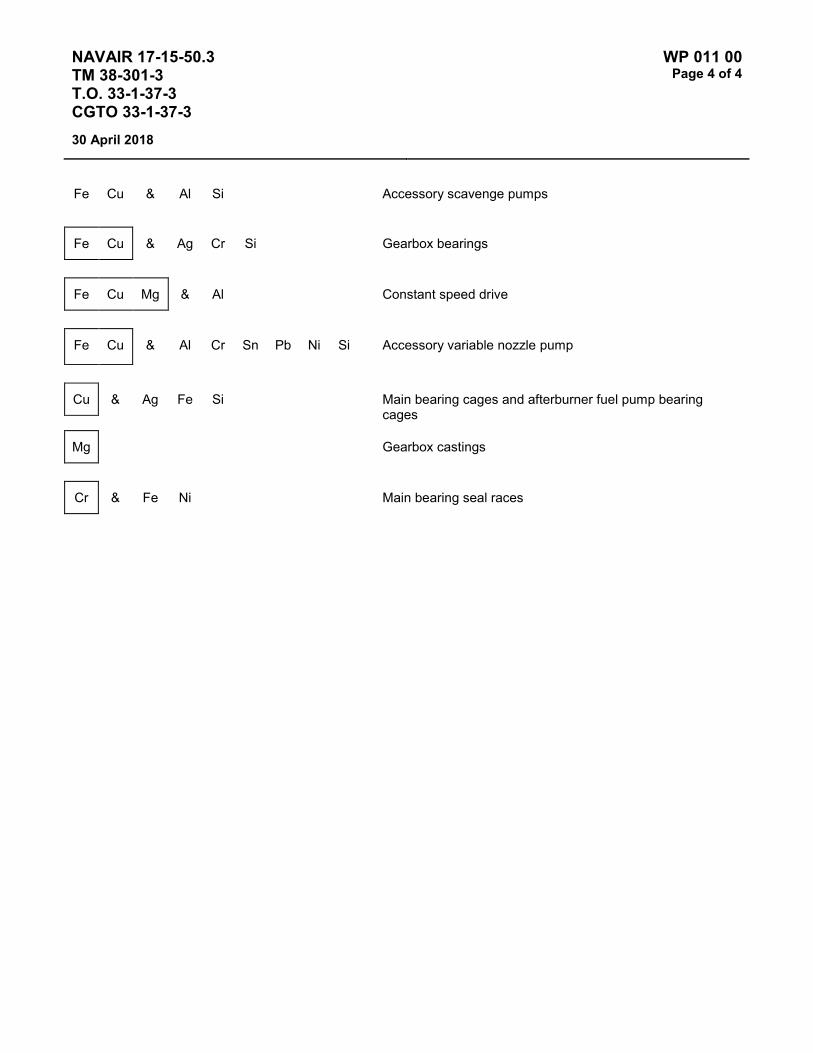
NAVAIR 17-15-50.3 TM 38-301-3 T.O. 33-1-37-3 CGTO 33-1-37-3
WP 011 00 Page 4 of 4
30 April 2018
Fe Cu & Al Si Accessory scavenge pumps
Fe Cu & Ag Cr Si Gearbox bearings
Fe Cu Mg & Al Constant speed drive
Fe Cu & Al Cr Sn Pb Ni Si Accessory variable nozzle pump
Cu & Ag Fe Si Main bearing cages and afterburner fuel pump bearing cages
Mg Gearbox castings
Cr & Fe Ni Main bearing seal races

NAVAIR 17-15-50.3 TM 38-301-3 T.O. 33-1-37-3 CGTO 33-1-37-3
WP 012 00 Page 1 of 4
30 April 2018
TYPE EQUIPMENT Aircraft Engine
MANUFACTURER General Electric
EQUIPMENT/SYSTEM MODEL NUMBER/DESIGNATION
WEAPON SYSTEM PLATFORM(S)
JOAP TYPE EQUIPMENT CODE
J85-GE-4A T-2C ERCA
J85-GE-4 T-2 ERBA
LUBRICATING OIL MIL-PRF-7808
TECHNICAL AUTHORITY Air Force
STATUS Aircraft retired – WP retained for reference.
Table 1 - JOAP ATOMIC EMISSION ROTRODE LIMITS
* Fe Ag Al Cr * Cu Mg B Si Zn
Abnormal Trend (PPM Increase in 10 Hrs)
9 3 4 3 5
Normal Range 0-35 0-5 0-12 0-4 0-16 Marginal Range 36-44 6-7 13-15 * 5-6 17-19 High Range * 45-53 8-10 16-17 13-14 20-23 Abnormal ≥54 ≥11 ≥18 ≥15 ≥24 10 10 10 NOTE: * Recommend remove if Fe and Cu are both in ranges indicated (High Fe and Marginal Cu). If iron (Fe) is in
the high range with copper (Cu) less than 5 PPM and nickel (Ni) is approximately 15% of the iron value, recommend that the unit be placed on 5 hour sampling intervals until next aircraft phase inspection or operated for 125 hours, whichever occurs first. Inspect compressor shaft for spline wear.
Elevated boron (B) and/or zinc (Zn) concentrations usually indicate contamination with another oil type, primarily MIL-PRF-2104. Recommend resampling and retesting immediately. If new value exceeds 8.0 PPM, run check with D19-0 to ensure proper instrument function. When proper function is confirmed, report both results and suspected contamination with MIL-PRF-2104 to chain of command, maintenance chief, cognizant engineering authority (Army and Navy only), and other personnel as specified by local written procedures. Recommend flushing and retesting of contaminated pre-oilers, carts, or other reservoirs where contamination is found until both B and Zn concentrations fall below 8.0 PPM. Refer to JOAP Manual Volume 2, WP 021 00 for more information. Recommend segregation of confirmed or suspected contaminated stocks, and submit information (batch no., lot no., MIL-PRF, nature of problem, etc.) on such stocks through the Defense supply deficiency reporting system.

NAVAIR 17-15-50.3 TM 38-301-3 T.O. 33-1-37-3 CGTO 33-1-37-3
WP 012 00 Page 2 of 4
30 April 2018
Elevated silicon (Si) concentration usually indicates contamination with soil, sand, or dust. If aluminum (Al) is also elevated, this suggests the presence of clay or soil. Recommend resampling and retesting immediately. If new value exceeds 8.0 PPM, run check with D19-0 to ensure proper instrument function. When proper function is confirmed, report both results and suspected contamination with soil, sand, or dust to chain of command, maintenance chief, cognizant engineering authority (Army and Navy only), and other personnel as specified by local written procedures. Recommend flushing and retesting of contaminated pre-oilers, carts, or other reservoirs where contamination is found until silicon concentration falls below 8.0 PPM. Refer to JOAP Manual Volume 2, WP 021 00 for more information. Recommend segregation of confirmed or suspected contaminated stocks, and submit information (batch no., lot no., MIL-PRF, nature of problem, etc.) on such stocks through the Defense supply deficiency reporting system.
When Fe trend is increasing and with increasing Cu, suspect main bearing or accessory bearing defect. Suspect first No. 1 main bearing; next, No. 2 main bearing or Axis "E" accessory bearing. High Fe is frequently due to Axis "C" aft carbon seal mating ring wearing into Axis "C" aft bearing inner race. High Fe is also due to combination of Axis "B" forward and Axis "F" forward bearing outer races spinning in their housings.
J85 Power Plant Change 5 provides for chromium plating of Axis "B" forward, Axis "C" aft and Axis "D" forward bearing housings. This change should reduce high Fe. Outer races turning will show increasing and high chromium. Fuel contamination can be detected by the sampling catching fire. Small concentrations of fuel will be detected by odor. Recommend inspection of fuel heat exchanger or fuel pump.
Fe & Ni No. 1 bearing races
Fe & Cr No. 1 bearing rollers and front frame casing Nos. 2 and 3 bearing support Accessory drive gearbox and PTO bearing balls/rollers and races Accessory drive gearbox seal and bearing housings
Fe & Cr Ni Gearbox bearing spinning in liners, PTO scavenge tube Main bearing carbon seal runners No. 1 bearing compressor rotor front shaft No. 2 bearing locknut and compressor driveshaft No. 3 bearing locknut and turbine wheel shaft PTO radial driveshaft, bevel gears, bearing housing, axial bearing support and retainer Accessory lube and scavenge pump spur gear, lube filter and oil cooler valve Accessory drive gearbox shaft and bevel gears
Fe & Cr Accessory drive gearbox gear locknut
Ni Si

NAVAIR 17-15-50.3 TM 38-301-3 T.O. 33-1-37-3 CGTO 33-1-37-3
WP 012 00 Page 3 of 4
30 April 2018
Fe & Cr PTO and No. 2 bearing retainer
Ni Mg Accessory drive gearbox spanner nuts
Fe & Cr Al Nos. 2 and 3 bearing balls/rollers and races Accessory drive gearbox seal mating rings Accessory lube and scavenge pump rotors, liners and blades
Al Accessory oil cooler housing, oil pressure transducer and oil tank Rotor wear in front frame sump
Al & Mg Si Accessory filter bypass relief valve housing
Al & Cu Accessory lube and scavenge pump housing
Mg Si
Cu & Al Accessory lube and scavenge pump bearings
Fe Pb Si
Mg Si & Main and PTO bearing cages
Fe Ag Accessory drive gearbox bearing cages

NAVAIR 17-15-50.3 TM 38-301-3 T.O. 33-1-37-3 CGTO 33-1-37-3
WP 012 00 Page 4 of 4
30 April 2018
This Page Intentionally Left Blank

NAVAIR 17-15-50.3 TM 38-301-3 T.O. 33-1-37-3 CGTO 33-1-37-3
WP 013 00 Page 1 of 4
30 April 2018
TYPE EQUIPMENT Aircraft Engine
MANUFACTURER General Electric
EQUIPMENT/SYSTEM MODEL NUMBER/DESIGNATION
WEAPON SYSTEM PLATFORM(S)
JOAP TYPE EQUIPMENT CODE
J85-GE-5 T-38 ERDA
J85-GE-13 F-5 EREA
LUBRICATING OIL MIL-PRF-7808 or MIL-PRF-23699
TECHNICAL AUTHORITY Air Force
STATUS In Use
Table 1 - JOAP ATOMIC EMISSION ROTRODE LIMITS
Fe Ag Al Cr Cu Mg B Si Zn
* Abnormal Trend (PPM Increase in 10 Hrs)*
10 2 2 3 3 4
Normal Range 0-10 0 0-1 0 0-1 0-3 Marginal Range 11-28 1-2 2-3 1-2 2-4 4-10 High Range 29-49 3-6 4-7 3-8 5-11 11-21 Abnormal ≥50 ≥7 ≥8 ≥9 ≥12 ≥22 10 10 10 NOTE: * If the calculated PPM trend value is equal to or greater than the trend PPM value limit, the engine has an
abnormal trend.
Elevated boron (B) and/or zinc (Zn) concentrations usually indicate contamination with another oil type, primarily MIL-PRF-2104. Recommend resampling and retesting immediately. If new value exceeds 8.0 PPM, run check with D19-0 to ensure proper instrument function. When proper function is confirmed, report both results and suspected contamination with MIL-PRF-2104 to chain of command, maintenance chief, cognizant engineering authority (Army and Navy only), and other personnel as specified by local written procedures. Recommend flushing and retesting of contaminated pre-oilers, carts, or other reservoirs where contamination is found until both B and Zn concentrations fall below 8.0 PPM. Refer to JOAP Manual Volume 2, WP 021 00 for more information. Recommend segregation of confirmed or suspected contaminated stocks, and submit information (batch no., lot no., MIL-PRF, nature of problem, etc.) on such stocks through the Defense supply deficiency reporting system.
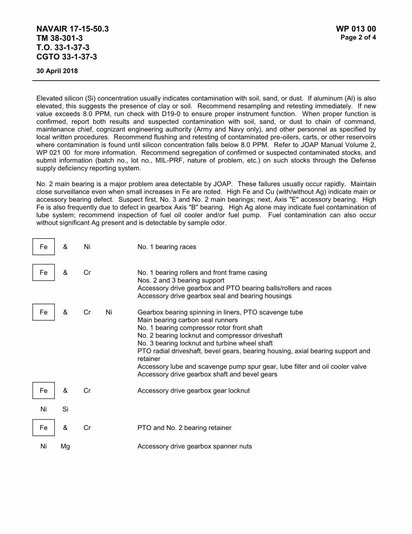
NAVAIR 17-15-50.3 TM 38-301-3 T.O. 33-1-37-3 CGTO 33-1-37-3
WP 013 00 Page 2 of 4
30 April 2018
Elevated silicon (Si) concentration usually indicates contamination with soil, sand, or dust. If aluminum (Al) is also elevated, this suggests the presence of clay or soil. Recommend resampling and retesting immediately. If new value exceeds 8.0 PPM, run check with D19-0 to ensure proper instrument function. When proper function is confirmed, report both results and suspected contamination with soil, sand, or dust to chain of command, maintenance chief, cognizant engineering authority (Army and Navy only), and other personnel as specified by local written procedures. Recommend flushing and retesting of contaminated pre-oilers, carts, or other reservoirs where contamination is found until silicon concentration falls below 8.0 PPM. Refer to JOAP Manual Volume 2, WP 021 00 for more information. Recommend segregation of confirmed or suspected contaminated stocks, and submit information (batch no., lot no., MIL-PRF, nature of problem, etc.) on such stocks through the Defense supply deficiency reporting system.
No. 2 main bearing is a major problem area detectable by JOAP. These failures usually occur rapidly. Maintain close surveillance even when small increases in Fe are noted. High Fe and Cu (with/without Ag) indicate main or accessory bearing defect. Suspect first, No. 3 and No. 2 main bearings; next, Axis "E" accessory bearing. High Fe is also frequently due to defect in gearbox Axis "B" bearing. High Ag alone may indicate fuel contamination of lube system; recommend inspection of fuel oil cooler and/or fuel pump. Fuel contamination can also occur without significant Ag present and is detectable by sample odor.
Fe & Ni No. 1 bearing races
Fe & Cr No. 1 bearing rollers and front frame casing Nos. 2 and 3 bearing support Accessory drive gearbox and PTO bearing balls/rollers and races Accessory drive gearbox seal and bearing housings
Fe & Cr Ni Gearbox bearing spinning in liners, PTO scavenge tube Main bearing carbon seal runners No. 1 bearing compressor rotor front shaft No. 2 bearing locknut and compressor driveshaft No. 3 bearing locknut and turbine wheel shaft PTO radial driveshaft, bevel gears, bearing housing, axial bearing support and retainer Accessory lube and scavenge pump spur gear, lube filter and oil cooler valve Accessory drive gearbox shaft and bevel gears
Fe & Cr Accessory drive gearbox gear locknut
Ni Si
Fe & Cr PTO and No. 2 bearing retainer
Ni Mg Accessory drive gearbox spanner nuts
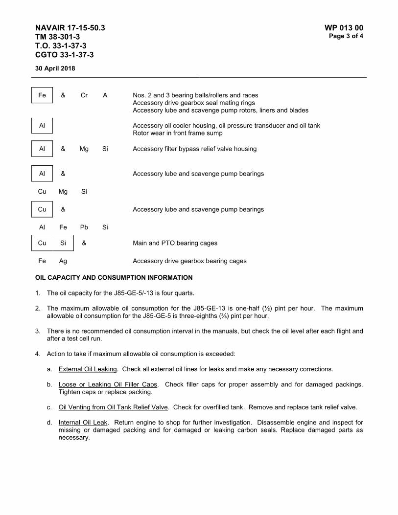
NAVAIR 17-15-50.3 TM 38-301-3 T.O. 33-1-37-3 CGTO 33-1-37-3
WP 013 00 Page 3 of 4
30 April 2018
Fe & Cr A Nos. 2 and 3 bearing balls/rollers and races Accessory drive gearbox seal mating rings Accessory lube and scavenge pump rotors, liners and blades
Al Accessory oil cooler housing, oil pressure transducer and oil tank Rotor wear in front frame sump
Al & Mg Si Accessory filter bypass relief valve housing
Al & Accessory lube and scavenge pump bearings
Cu Mg Si
Cu & Accessory lube and scavenge pump bearings
Al Fe Pb Si
Cu Si & Main and PTO bearing cages
Fe Ag Accessory drive gearbox bearing cages
OIL CAPACITY AND CONSUMPTION INFORMATION
1. The oil capacity for the J85-GE-5/-13 is four quarts.
2. The maximum allowable oil consumption for the J85-GE-13 is one-half (½) pint per hour. The maximum allowable oil consumption for the J85-GE-5 is three-eighths (⅜) pint per hour.
3. There is no recommended oil consumption interval in the manuals, but check the oil level after each flight and after a test cell run.
4. Action to take if maximum allowable oil consumption is exceeded:
a. External Oil Leaking. Check all external oil lines for leaks and make any necessary corrections.
b. Loose or Leaking Oil Filler Caps. Check filler caps for proper assembly and for damaged packings. Tighten caps or replace packing.
c. Oil Venting from Oil Tank Relief Valve. Check for overfilled tank. Remove and replace tank relief valve.
d. Internal Oil Leak. Return engine to shop for further investigation. Disassemble engine and inspect for missing or damaged packing and for damaged or leaking carbon seals. Replace damaged parts as necessary.

NAVAIR 17-15-50.3 TM 38-301-3 T.O. 33-1-37-3 CGTO 33-1-37-3
WP 013 00 Page 4 of 4
30 April 2018
This Page Intentionally left Blank

NAVAIR 17-15-50.3 TM 38-301-3 T.O. 33-1-37-3 CGTO 33-1-37-3
WP 014 00 Page 1 of 4
30 April 2018
TYPE EQUIPMENT Aircraft Engine
MANUFACTURER General Electric
EQUIPMENT/SYSTEM MODEL NUMBER/DESIGNATION
WEAPON SYSTEM PLATFORM(S)
JOAP TYPE EQUIPMENT CODE
J85-GE-21/-21B/-21C F-5E/F ERGA
LUBRICATING OIL MIL-PRF-23699 or MIL-PRF-7808
TECHNICAL AUTHORITY NAVAIR
STATUS In Use
Table 1 - JOAP ATOMIC EMISSION ROTRODE LIMITS
Fe Ag Al Cr Cu Mg Ti B Si Zn
* Abnormal Trend (PPM Increase in 10 Hrs)*
10 2 2 3 3 4 3
Normal Range 0-16 0-1 0-1 0-1 0-1 0-3 0-2 Marginal Range 17-38 2 2 2 2 4-9 3 High Range 39-49 3 3 3 3 10-15 4 Abnormal ≥50 ≥4 ≥4 ≥4 ≥4 ≥16 ≥5 10 10 10 NOTE: * If the calculated PPM trend value is equal to or greater than the trend PPM value limit, the engine has an
abnormal trend.
Elevated boron (B) and/or zinc (Zn) concentrations usually indicate contamination with another oil type, primarily MIL-PRF-2104. Recommend resampling and retesting immediately. If new value exceeds 8.0 PPM, run check with D19-0 to ensure proper instrument function. When proper function is confirmed, report both results and suspected contamination with MIL-PRF-2104 to chain of command, maintenance chief, cognizant engineering authority (Army and Navy only), and other personnel as specified by local written procedures. Recommend flushing and retesting of contaminated pre-oilers, carts, or other reservoirs where contamination is found until both B and Zn concentrations fall below 8.0 PPM. Refer to JOAP Manual Volume 2, WP 021 00 for more information. Recommend segregation of confirmed or suspected contaminated stocks, and submit information (batch no., lot no., MIL-PRF, nature of problem, etc.) on such stocks through the Defense supply deficiency reporting system.
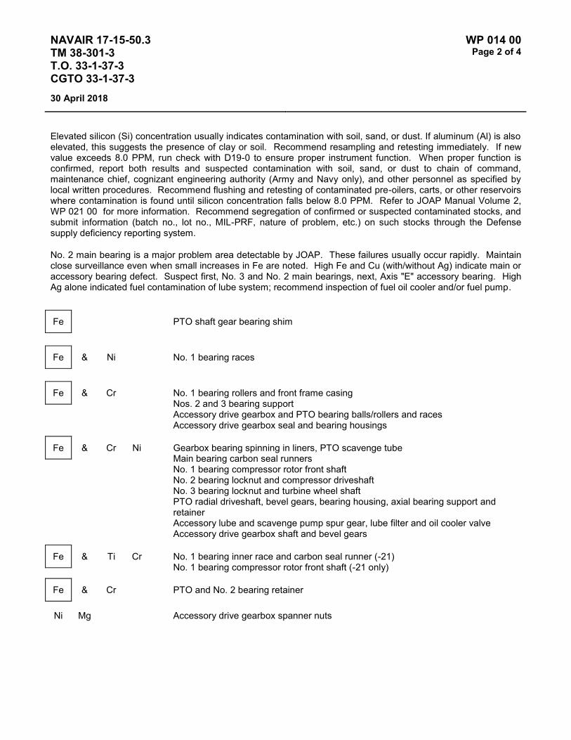
NAVAIR 17-15-50.3 TM 38-301-3 T.O. 33-1-37-3 CGTO 33-1-37-3
WP 014 00 Page 2 of 4
30 April 2018
Elevated silicon (Si) concentration usually indicates contamination with soil, sand, or dust. If aluminum (Al) is also elevated, this suggests the presence of clay or soil. Recommend resampling and retesting immediately. If new value exceeds 8.0 PPM, run check with D19-0 to ensure proper instrument function. When proper function is confirmed, report both results and suspected contamination with soil, sand, or dust to chain of command, maintenance chief, cognizant engineering authority (Army and Navy only), and other personnel as specified by local written procedures. Recommend flushing and retesting of contaminated pre-oilers, carts, or other reservoirs where contamination is found until silicon concentration falls below 8.0 PPM. Refer to JOAP Manual Volume 2, WP 021 00 for more information. Recommend segregation of confirmed or suspected contaminated stocks, and submit information (batch no., lot no., MIL-PRF, nature of problem, etc.) on such stocks through the Defense supply deficiency reporting system.
No. 2 main bearing is a major problem area detectable by JOAP. These failures usually occur rapidly. Maintain close surveillance even when small increases in Fe are noted. High Fe and Cu (with/without Ag) indicate main or accessory bearing defect. Suspect first, No. 3 and No. 2 main bearings, next, Axis "E" accessory bearing. High Ag alone indicated fuel contamination of lube system; recommend inspection of fuel oil cooler and/or fuel pump.
Fe PTO shaft gear bearing shim
Fe & Ni No. 1 bearing races
Fe & Cr No. 1 bearing rollers and front frame casing Nos. 2 and 3 bearing support Accessory drive gearbox and PTO bearing balls/rollers and races Accessory drive gearbox seal and bearing housings
Fe & Cr Ni Gearbox bearing spinning in liners, PTO scavenge tube Main bearing carbon seal runners No. 1 bearing compressor rotor front shaft No. 2 bearing locknut and compressor driveshaft No. 3 bearing locknut and turbine wheel shaft PTO radial driveshaft, bevel gears, bearing housing, axial bearing support and retainer Accessory lube and scavenge pump spur gear, lube filter and oil cooler valve Accessory drive gearbox shaft and bevel gears
Fe & Ti Cr No. 1 bearing inner race and carbon seal runner (-21) No. 1 bearing compressor rotor front shaft (-21 only)
Fe & Cr PTO and No. 2 bearing retainer
Ni Mg Accessory drive gearbox spanner nuts

NAVAIR 17-15-50.3 TM 38-301-3 T.O. 33-1-37-3 CGTO 33-1-37-3
WP 014 00 Page 3 of 4
30 April 2018
Fe & Accessory drive gearbox gear locknut
Cr Ni Si
Fe & Cr Al Nos. 2 and 3 bearing balls/rollers and races Accessory drive gearbox seal mating rings Accessory lube and scavenge pump rotors, liners and blades
Al Accessory oil cooler housing, oil pressure transducer and oil tank Rotor wear in front frame sump
Al & Mg Si Accessory filter bypass relief valve housing
Al & Accessory lube and scavenge pump bearings
Cu Mg Si
Cu & Accessory lube and scavenge pump bearings
Al Fe Pb Si
Cu Si & Main and PTO bearing cages
Fe Ag Accessory drive gearbox bearing cages
OIL CAPACITY AND CONSUMPTION INFORMATION
1. The oil capacity for the J85-GE-21 is four quarts.
2. The maximum allowable oil consumption rate (quantity per time) for the J85-GE-21 is one-half (½) pint per hour.
3. There is no recommended oil consumption interval in the manuals, but check the oil level after each flight and after a test cell run.
4. Action to take if maximum allowable oil consumption is exceeded:
a. External Oil Leaking. Check all external oil lines for leaks and make any necessary corrections.
b. Loose or Leaking Oil Filler Caps. Check filler caps for proper assembly and for damaged packings. Tighten caps or replace packing.
c. Oil Venting from Oil Tank Relief Valve. Check for overfilled tank. Remove and replace tank relief valve.

NAVAIR 17-15-50.3 TM 38-301-3 T.O. 33-1-37-3 CGTO 33-1-37-3
WP 014 00 Page 4 of 4
30 April 2018
d. Internal Oil Leak. Return engine to shop for further investigation. Disassemble engine and inspect for missing or damaged packings and for damaged or leaking carbon seals. Replace damaged parts as necessary.
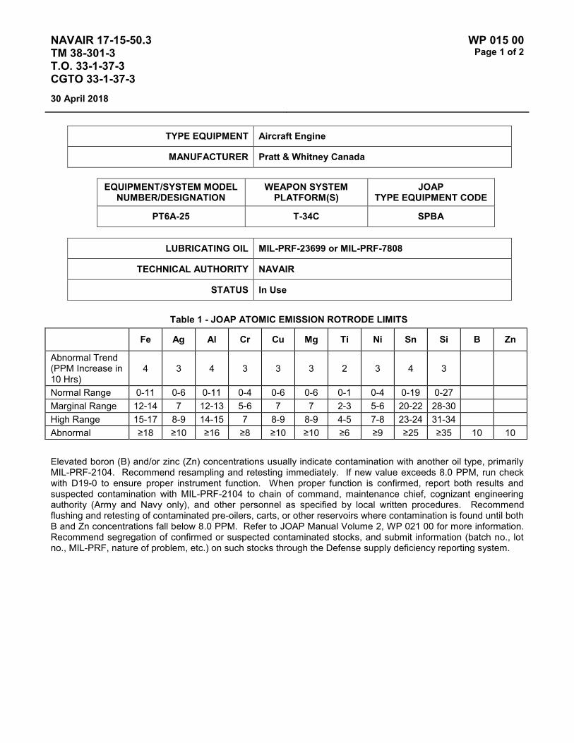
NAVAIR 17-15-50.3 TM 38-301-3 T.O. 33-1-37-3 CGTO 33-1-37-3
WP 015 00 Page 1 of 2
30 April 2018
TYPE EQUIPMENT Aircraft Engine
MANUFACTURER Pratt & Whitney Canada
EQUIPMENT/SYSTEM MODEL NUMBER/DESIGNATION
WEAPON SYSTEM PLATFORM(S)
JOAP TYPE EQUIPMENT CODE
PT6A-25 T-34C SPBA
LUBRICATING OIL MIL-PRF-23699 or MIL-PRF-7808
TECHNICAL AUTHORITY NAVAIR
STATUS In Use
Table 1 - JOAP ATOMIC EMISSION ROTRODE LIMITS
Fe Ag Al Cr Cu Mg Ti Ni Sn Si B Zn
Abnormal Trend (PPM Increase in 10 Hrs)
4 3 4 3 3 3 2 3 4 3
Normal Range 0-11 0-6 0-11 0-4 0-6 0-6 0-1 0-4 0-19 0-27 Marginal Range 12-14 7 12-13 5-6 7 7 2-3 5-6 20-22 28-30 High Range 15-17 8-9 14-15 7 8-9 8-9 4-5 7-8 23-24 31-34 Abnormal ≥18 ≥10 ≥16 ≥8 ≥10 ≥10 ≥6 ≥9 ≥25 ≥35 10 10
Elevated boron (B) and/or zinc (Zn) concentrations usually indicate contamination with another oil type, primarily MIL-PRF-2104. Recommend resampling and retesting immediately. If new value exceeds 8.0 PPM, run check with D19-0 to ensure proper instrument function. When proper function is confirmed, report both results and suspected contamination with MIL-PRF-2104 to chain of command, maintenance chief, cognizant engineering authority (Army and Navy only), and other personnel as specified by local written procedures. Recommend flushing and retesting of contaminated pre-oilers, carts, or other reservoirs where contamination is found until both B and Zn concentrations fall below 8.0 PPM. Refer to JOAP Manual Volume 2, WP 021 00 for more information. Recommend segregation of confirmed or suspected contaminated stocks, and submit information (batch no., lot no., MIL-PRF, nature of problem, etc.) on such stocks through the Defense supply deficiency reporting system.

NAVAIR 17-15-50.3 TM 38-301-3 T.O. 33-1-37-3 CGTO 33-1-37-3
WP 015 00 Page 2 of 2
30 April 2018
Fe Accessory gears, main bearings, races and splines
Fe Cu Ag Main bearings and bearing cages
Fe Cu Al Accessory bushing bearing turning in magnesium housing
Fe Cu Mg Accessory bushing bearing turning in magnesium housing
Ag Plating on bearing cages
Si Oil contamination
Sn Plating on planet gear bearing carriers

NAVAIR 17-15-50.3 TM 38-301-3 T.O. 33-1-37-3 CGTO 33-1-37-3
WP 016 00 Page 1 of 2
30 April 2018
TYPE EQUIPMENT Aircraft Engine
MANUFACTURER Pratt & Whitney Canada
EQUIPMENT/SYSTEM MODEL NUMBER/DESIGNATION
WEAPON SYSTEM PLATFORM(S)
JOAP TYPE EQUIPMENT CODE
PT6A-34B T-44A/B SPFB
LUBRICATING OIL MIL-PRF-23699 or MIL-PRF-7808
TECHNICAL AUTHORITY NAVAIR
STATUS In Use
Table 1 - JOAP ATOMIC EMISSION ROTRODE LIMITS
Fe Ag Al Cr Cu Mg Ti Ni Sn Si B Zn
Abnormal Trend (PPM Increase in 10 Hrs)
4 3 4 3 3 3 2 3 4 3
Normal Range 0-11 0-6 0-11 0-4 0-6 0-6 0-1 0-4 0-19 0-27 Marginal Range 12-14 7 12-13 5-6 7 7 2-3 5-6 20-22 28-30 High Range 15-17 8-9 14-15 7 8-9 8-9 4-5 7-8 23-24 31-34 Abnormal ≥18 ≥10 ≥16 ≥8 ≥10 ≥10 ≥6 ≥9 ≥25 ≥35 10 10
Elevated boron (B) and/or zinc (Zn) concentrations usually indicate contamination with another oil type, primarily MIL-PRF-2104. Recommend resampling and retesting immediately. If new value exceeds 8.0 PPM, run check with D19-0 to ensure proper instrument function. When proper function is confirmed, report both results and suspected contamination with MIL-PRF-2104 to chain of command, maintenance chief, cognizant engineering authority (Army and Navy only), and other personnel as specified by local written procedures. Recommend flushing and retesting of contaminated pre-oilers, carts, or other reservoirs where contamination is found until both B and Zn concentrations fall below 8.0 PPM. Refer to JOAP Manual Volume 2, WP 021 00 for more information. Recommend segregation of confirmed or suspected contaminated stocks, and submit information (batch no., lot no., MIL-PRF, nature of problem, etc.) on such stocks through the Defense supply deficiency reporting system.

NAVAIR 17-15-50.3 TM 38-301-3 T.O. 33-1-37-3 CGTO 33-1-37-3
WP 016 00 Page 2 of 2
30 April 2018
Fe Accessory gears, main bearings, races and splines
Fe Cu Ag Main bearings and bearing cages
Fe Cu Al Accessory bushing bearing turning in magnesium housing
Fe Cu Mg Accessory bushing bearing turning in magnesium housing
Ag Plating on bearing cages
Si Oil contamination
Sn Plating on planet gear bearing carriers

NAVAIR 17-15-50.3 TM 38-301-3 T.O. 33-1-37-3 CGTO 33-1-37-3
WP 017 00 Page 1 of 2
30 April 2018
TYPE EQUIPMENT Aircraft Engine
MANUFACTURER Pratt & Whitney Canada
EQUIPMENT/SYSTEM MODEL NUMBER/DESIGNATION
WEAPON SYSTEM PLATFORM(S)
JOAP TYPE EQUIPMENT CODE
PT6A-68 T-6A/B SPQA
LUBRICATING OIL MIL-PRF-23699
TECHNICAL AUTHORITY Air Force and NAVAIR
STATUS In Use
Table 1 - JOAP ATOMIC EMISSION ROTRODE LIMITS
Fe Ag Al Cr Cu Mg Ni Si Ti B Zn
Abnormal Trend (PPM Increase in 10 Hrs)
3 3 4 3 3 3 3 10 2
Normal Range 0-6 0-3 0-6 0-2 0-3 0-2 0-3 0-10 0-3 Marginal Range 7-11 4-6 7-11 3-4 4-6 3-4 4-5 11-27 4-5 High Range 12-15 7-8 12-16 5-6 7-9 5-6 6-7 28-34 6-7 Abnormal ≥16 ≥9 ≥17 ≥7 ≥10 ≥7 ≥8 ≥35 ≥8 10 10
Elevated boron (B) and/or zinc (Zn) concentrations usually indicate contamination with another oil type, primarily MIL-PRF-2104. Recommend resampling and retesting immediately. If new value exceeds 8.0 PPM, run check with D19-0 to ensure proper instrument function. When proper function is confirmed, report both results and suspected contamination with MIL-PRF-2104 to chain of command, maintenance chief, cognizant engineering authority (Army and Navy only), and other personnel as specified by local written procedures. Recommend flushing and retesting of contaminated pre-oilers, carts, or other reservoirs where contamination is found until both B and Zn concentrations fall below 8.0 PPM. Refer to JOAP Manual Volume 2, WP 021 00 for more information. Recommend segregation of confirmed or suspected contaminated stocks, and submit information (batch no., lot no., MIL-PRF, nature of problem, etc.) on such stocks through the Defense supply deficiency reporting system.
The corresponding recommended maintenance action for the PT6A-6B engine based on the JOAP results is as follows:
1. Normal or Marginal Range. Continue engine in service and maintain normal sampling schedule.
2. High or Abnormal Range.
a. Inspect the engine oil filter element. If the engine is serviceable per maintenance manual, continue in service.
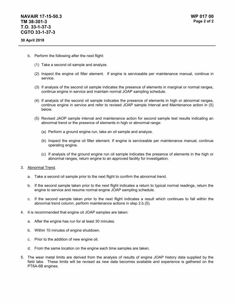
NAVAIR 17-15-50.3 TM 38-301-3 T.O. 33-1-37-3 CGTO 33-1-37-3
WP 017 00 Page 2 of 2
30 April 2018
b. Perform the following after the next flight:
(1) Take a second oil sample and analyze.
(2) Inspect the engine oil filter element. If engine is serviceable per maintenance manual, continue in service.
(3) If analysis of the second oil sample indicates the presence of elements in marginal or normal ranges, continue engine in service and maintain normal JOAP sampling schedule.
(4) If analysis of the second oil sample indicates the presence of elements in high or abnormal ranges, continue engine in service and refer to revised JOAP sample Interval and Maintenance action in (5) below.
(5) Revised JAOP sample interval and maintenance action for second sample test results indicating an abnormal trend or the presence of elements in high or abnormal range:
(a) Perform a ground engine run, take an oil sample and analyze.
(b) Inspect the engine oil filter element. If engine is serviceable per maintenance manual, continue operating engine.
(c) If analysis of the ground engine run oil sample indicates the presence of elements in the high or abnormal ranges, return engine to an approved facility for investigation.
3. Abnormal Trend.
a. Take a second oil sample prior to the next flight to confirm the abnormal trend.
b. If the second sample taken prior to the next flight indicates a return to typical normal readings, return the engine to service and resume normal engine JOAP sampling schedule.
c. If the second sample taken prior to the next flight indicates a result which continues to fall within the abnormal trend column, perform maintenance actions in step 2.b.(5).
4. It is recommended that engine oil JOAP samples are taken:
a. After the engine has run for at least 30 minutes.
b. Within 10 minutes of engine shutdown.
c. Prior to the addition of new engine oil.
d. From the same location on the engine each time samples are taken.
5. The wear metal limits are derived from the analysis of results of engine JOAP history data supplied by the field labs. These limits will be revised as new data becomes available and experience is gathered on the PT6A-6B engines.

NAVAIR 17-15-50.3 TM 38-301-3 T.O. 33-1-37-3 CGTO 33-1-37-3
WP 018 00 Page 1 of 2
30 April 2018
TYPE EQUIPMENT Aircraft Engine
MANUFACTURER Lycoming
EQUIPMENT/SYSTEM MODEL NUMBER/DESIGNATION
WEAPON SYSTEM PLATFORM(S)
JOAP TYPE EQUIPMENT CODE
T53-L-13B, T53-L-703 UH-1H, TH-1H SBEE
LUBRICATING OIL MIL-PRF-7808 or MIL-PRF-23699
TECHNICAL AUTHORITY Air Force
STATUS In Use
Table 1 - JOAP ATOMIC EMISSION ROTRODE LIMITS
Fe Ag Al Cr Cu Mg Si B Zn
* Abnormal Trend (PPM Increase in 10 Hrs)*
4 2 4 2 3 4 10
Normal Range 0-10 0 0 0 0 0 0-15 Marginal Range 11-16 1-3 1-12 1-6 1-9 1-12 16-40 High Range 17-19 4 13-14 7 10-11 13-14 41-49 Abnormal ≥20 ≥5 ≥15 ≥8 ≥12 ≥15 ≥50 10 10 NOTE: * If the calculated PPM trend value is equal to or greater than the trend PPM value limit, the engine has an
abnormal trend.
Elevated boron (B) and/or zinc (Zn) concentrations usually indicate contamination with another oil type, primarily MIL-PRF-2104. Recommend resampling and retesting immediately. If new value exceeds 8.0 PPM, run check with D19-0 to ensure proper instrument function. When proper function is confirmed, report both results and suspected contamination with MIL-PRF-2104 to chain of command, maintenance chief, cognizant engineering authority (Army and Navy only), and other personnel as specified by local written procedures. Recommend flushing and retesting of contaminated pre-oilers, carts, or other reservoirs where contamination is found until both B and Zn concentrations fall below 8.0 PPM. Refer to JOAP Manual Volume 2, WP 021 00 for more information. Recommend segregation of confirmed or suspected contaminated stocks, and submit information (batch no., lot no., MIL-PRF, nature of problem, etc.) on such stocks through the Defense supply deficiency reporting system.

NAVAIR 17-15-50.3 TM 38-301-3 T.O. 33-1-37-3 CGTO 33-1-37-3
WP 018 00 Page 2 of 2
30 April 2018
This Page Intentionally Left Blank

NAVAIR 17-15-50.3 TM 38-301-3 T.O. 33-1-37-3 CGTO 33-1-37-3
WP 019 00 Page 1 of 2
30 April 2018
TYPE EQUIPMENT Aircraft Engine
MANUFACTURER Lycoming
EQUIPMENT/SYSTEM MODEL NUMBER/DESIGNATION
WEAPON SYSTEM PLATFORM(S)
JOAP TYPE EQUIPMENT CODE
T53-L-13B UH-1H SBEE
T53-L-11 UH-1V SBCC
T53-L-13B UH-1V SBEG
T53-L-13B UH-1X SBEH
LUBRICATING OIL MIL-PRF-23699 or MIL-PRF-7808
TECHNICAL AUTHORITY Army Aviation Command
STATUS In Use
Table 1 - JOAP ATOMIC EMISSION ROTRODE LIMITS
Fe Al Cr Cu Mg Si B Zn
Abnormal Trend (PPM Increase in 10 Hrs)
3 2 2 2 2 4
Normal Range 0-6 0-1 0-1 0-2 0-3 0-15 Marginal Range 7 N/A 1 2 N/A 16-17 High Range 8-9 2 2 3 4 18-23 Abnormal ≥10 ≥3 ≥3 ≥4 ≥5 ≥24 10 10
Elevated boron (B) and/or zinc (Zn) concentrations usually indicate contamination with another oil type, primarily MIL-PRF-2104. Recommend resampling and retesting immediately. If new value exceeds 8.0 PPM, run check with D19-0 to ensure proper instrument function. When proper function is confirmed, report both results and suspected contamination with MIL-PRF-2104 to chain of command, maintenance chief, cognizant engineering authority (Army and Navy only), and other personnel as specified by local written procedures. Recommend flushing and retesting of contaminated pre-oilers, carts, or other reservoirs where contamination is found until both B and Zn concentrations fall below 8.0 PPM. Refer to JOAP Manual Volume 2, WP 021 00 for more information. Recommend segregation of confirmed or suspected contaminated stocks, and submit information (batch no., lot no., MIL-PRF, nature of problem, etc.) on such stocks through the Defense supply deficiency reporting system.

NAVAIR 17-15-50.3 TM 38-301-3 T.O. 33-1-37-3 CGTO 33-1-37-3
WP 019 00 Page 2 of 2
30 April 2018
Fe Bearing Speed reduction or accessory drive gearing, spacer, shims or splines
Fe & Cu Bearings
Fe Ag & Cu Main bearing or Gear Assemblies
Fe & Mg Accessory bearing lining and case
NOTES
1. Cr along with a sharp increase in Fe and oil consumption will be associated with plating wear on carbon seal journals.
2. High Si indicates contamination probably due to sampling error.
OIL CAPACITY AND CONSUMPTION INFORMATION AIR FORCE REFERENCE MATERIAL ONLY
T.O. Reference: 1H-1(H)H-2-1, Paragraph 2-82
1. Oil capacity of engine is 3.0 U.S. gallons.
2. Allowable oil consumption rate (quantity per time) is 3 pints per hour.
3. Recommended oil consumption inspection interval (if appropriate for your engine): After every flight during postflight inspection. Limit is 3 pints per hour.
4. Action to take if maximum allowable oil consumption is exceeded: Remove and repair engine at appropriate level maintenance, if not return to Depot.

NAVAIR 17-15-50.3 TM 38-301-3 T.O. 33-1-37-3 CGTO 33-1-37-3
WP 020 00 Page 1 of 2
30 April 2018
TYPE EQUIPMENT Aircraft Engine
MANUFACTURER Lycoming / Honeywell Aerospace
EQUIPMENT/SYSTEM MODEL NUMBER/DESIGNATION
WEAPON SYSTEM PLATFORM(S)
JOAP TYPE EQUIPMENT CODE
T55-L-712 CH-47D SCDB
T55-L-714 CH-47D SCED
T55-L-712 CH-47F SCEV
T55-L-714 CH-47F SCEE
T55-L-714 MH-47E SCDC
T55-GA-714A MH-47G SCEH
LUBRICATING OIL MIL-PRF-23699 or MIL-PRF-7808
TECHNICAL AUTHORITY Army Aviation Command
STATUS In Use
Table 1 - JOAP ATOMIC EMISSION ROTRODE LIMITS
Fe Ag Al Cr Cu Mg Si B Zn
Abnormal Trend (PPM Increase in 10 Hrs)
2 2 2 2 2 2 2
Normal Range 0-4 1 1 1 1 0-5 0-7 Marginal Range * 5 2 2 2 2 6-7 8-9 High Range 6 3 3 3 3 8 10-11 Abnormal ≥7 ≥4 ≥4 ≥4 ≥4 ≥9 ≥12 10 10
Elevated boron (B) and/or zinc (Zn) concentrations usually indicate contamination with another oil type, primarily MIL-PRF-2104. Recommend resampling and retesting immediately. If new value exceeds 8.0 PPM, run check with D19-0 to ensure proper instrument function. When proper function is confirmed, report both results and suspected contamination with MIL-PRF-2104 to chain of command, maintenance chief, cognizant engineering authority (Army and Navy only), and other personnel as specified by local written procedures. Recommend flushing and retesting of contaminated pre-oilers, carts, or other reservoirs where contamination is found until both B and Zn concentrations fall below 8.0 PPM. Refer to JOAP Manual Volume 2, WP 021 00 for more information. Recommend segregation of confirmed or suspected contaminated stocks, and submit information (batch no., lot no., MIL-PRF, nature of problem, etc.) on such stocks through the Defense supply deficiency reporting system.

NAVAIR 17-15-50.3 TM 38-301-3 T.O. 33-1-37-3 CGTO 33-1-37-3
WP 020 00 Page 2 of 2
30 April 2018
Elevated silicon (Si) concentration usually indicates contamination with soil, sand, or dust. If aluminum (Al) is also elevated, this suggests the presence of clay or soil. Recommend resampling and retesting immediately. If new value exceeds 8.0 PPM, run check with D19-0 to ensure proper instrument function. When proper function is confirmed, report both results and suspected contamination with soil, sand, or dust to chain of command, maintenance chief, cognizant engineering authority (Army and Navy only), and other personnel as specified by local written procedures. Recommend flushing and retesting of contaminated pre-oilers, carts, or other reservoirs where contamination is found until silicon concentration falls below 8.0 PPM. Refer to JOAP Manual Volume 2, WP 021 00 for more information. Recommend segregation of confirmed or suspected contaminated stocks, and submit information (batch no., lot no., MIL-PRF, nature of problem, etc.) on such stocks through the Defense supply deficiency reporting system.

NAVAIR 17-15-50.3 TM 38-301-3 T.O. 33-1-37-3 CGTO 33-1-37-3
WP 021 00 Page 1 of 4
30 April 2018
TYPE EQUIPMENT Aircraft Engine
MANUFACTURER Allison (Rolls Royce)
EQUIPMENT/SYSTEM MODEL NUMBER/DESIGNATION
WEAPON SYSTEM PLATFORM(S)
JOAP TYPE EQUIPMENT CODE
T56-A-15 C-130 SDFA
T56-A-15 Gbx C-130 GTMF
T56-A-7 C-130 SDAA
T56-A-9 C-130 SDCA
T56-A-9 Gbx C-130 GTMC
T56-A-10 Test Cell SDDX
T56-A-14 Test Cell SDEX
T56-A-16 Test Cell SDGX
T56-A-425 Test Cell SDHX
T56-A-426 Test Cell SDJX
T56-A-7B Test Cell SDBX
LUBRICATING OIL MIL-PRF-23699 or MIL-PRF-7808
TECHNICAL AUTHORITY NAVAIR
STATUS In Use (for test cell and special samples)
Table 1 - JOAP ATOMIC EMISSION ROTRODE LIMITS
Fe Ag Al Cr Cu Mg B Si Zn
Abnormal Trend (PPM Increase in 10 Hrs)
10 3 3 3 5 9
Normal Range 0-35 0-6 0-6 0-6 0-12 0-37 Marginal Range 36-45 7-9 7 7 13-18 38-48 High Range 46-54 10-11 8-9 8-9 19-24 49-59 Abnormal ≥55 ≥12 ≥10 ≥10 ≥25 ≥60 10 10 10

NAVAIR 17-15-50.3 TM 38-301-3 T.O. 33-1-37-3 CGTO 33-1-37-3
WP 021 00 Page 2 of 4
30 April 2018
Elevated boron (B) and/or zinc (Zn) concentrations usually indicate contamination with another oil type, primarily MIL-PRF-2104. Recommend resampling and retesting immediately. If new value exceeds 8.0 PPM, run check with D19-0 to ensure proper instrument function. When proper function is confirmed, report both results and suspected contamination with MIL-PRF-2104 to chain of command, maintenance chief, cognizant engineering authority (Army and Navy only), and other personnel as specified by local written procedures. Recommend flushing and retesting of contaminated pre-oilers, carts, or other reservoirs where contamination is found until both B and Zn concentrations fall below 8.0 PPM. Refer to JOAP Manual Volume 2, WP 021 00 for more information. Recommend segregation of confirmed or suspected contaminated stocks, and submit information (batch no., lot no., MIL-PRF, nature of problem, etc.) on such stocks through the Defense supply deficiency reporting system.
Elevated silicon (Si) concentration usually indicates contamination with soil, sand, or dust. If aluminum (Al) is also elevated, this suggests the presence of clay or soil. Recommend resampling and retesting immediately. If new value exceeds 8.0 PPM, run check with D19-0 to ensure proper instrument function. When proper function is confirmed, report both results and suspected contamination with soil, sand, or dust to chain of command, maintenance chief, cognizant engineering authority (Army and Navy only), and other personnel as specified by local written procedures. Recommend flushing and retesting of contaminated pre-oilers, carts, or other reservoirs where contamination is found until silicon concentration falls below 8.0 PPM. Refer to JOAP Manual Volume 2, WP 021 00 for more information. Recommend segregation of confirmed or suspected contaminated stocks, and submit information (batch no., lot no., MIL-PRF, nature of problem, etc.) on such stocks through the Defense supply deficiency reporting system.
Caution must be exercised when evaluating this system since the power section and reduction gearbox are lubricated with the same oil supply. Reduction gearbox lube pump failures are usually indicated when Mg increases with some increase in Fe and Cu in combination. Reduction gearbox lube pump should be visually inspected for galling of end plate and pump body. When Fe increase is more than Cu increase, accompanied by moderate increase in Mg and small amount of Cr and Ag, discrepancy is usually with reduction gearbox pinion bearing. When increase in Fe and Mg occur, accompanied by moderate increases in Cu with small amount of Cr and Ag, then discrepancy is usually in one of three components: Power section side gear bearing, accessory case bearing, or reduction gearbox oil pump drive gear bearing. A significant increase in Fe in absence of other wear metals may indicate discrepancy in reduction gear train and/or rear turbine scavenge pump assembly. Dislocation of main drive gear vibration dampener is usually indicated by a rapid increase in Mg with possibly some increase in Fe.
Inspection of vibration damper on G56/-7/15 may be accomplished through unused generator drive pad. Inspection on G56-9 requires removal of rear case.
Fe Main bearing balls/rollers and races Reduction gear assembly gears Accessory drive gears, shafts and splines
Fe Cu & Si Accessory diffuser scavenge pump
Fe Cu & Si Mg Accessory turbine scavenge pump

NAVAIR 17-15-50.3 TM 38-301-3 T.O. 33-1-37-3 CGTO 33-1-37-3
WP 021 00 Page 3 of 4
30 April 2018
Fe Mg Accessory drive housing
Mg Reduction gear assembly oil pump
Cu Mg Reduction gear assembly oil pump
Cu Ag & Fe Si Main bearing cages Reduction gear assembly bearings
NOTE
The T-56 engine has been removed from the oil analysis program by the US Air Force and US Navy. The information above is retained for information purposes.

NAVAIR 17-15-50.3 TM 38-301-3 T.O. 33-1-37-3 CGTO 33-1-37-3
WP 021 00 Page 4 of 4
30 April 2018
This Page Intentionally Left Blank

NAVAIR 17-15-50.3 TM 38-301-3 T.O. 33-1-37-3 CGTO 33-1-37-3
WP 022 00 Page 1 of 2
30 April 2018
TYPE EQUIPMENT Aircraft Engine
MANUFACTURER General Electric
EQUIPMENT/SYSTEM MODEL NUMBER/DESIGNATION
WEAPON SYSTEM PLATFORM(S)
JOAP TYPE EQUIPMENT CODE
T58-GE-3 H-3 SEAA
T58-GE-8 H-52 SECA
T58-GE-8F H-2 SEDA
T58-GE-8F H-3 SEDB
T58-GE-10 H-3 SEEA
T58-GE-10 H-46 SEEB
LUBRICATING OIL MIL-PRF-23699 or MIL-PRF-7808
TECHNICAL AUTHORITY NAVAIR
STATUS Engines replaced. WP retained for reference.
Table 1 - JOAP ATOMIC EMISSION ROTRODE LIMITS
Fe Ag Al Cr Cu Mg B Si Zn
Abnormal Trend (PPM Increase in 10 Hrs)
8 2 4 2 4 3
Normal Range 0-26 0-2 0-10 0-3 0-10 0-8 Marginal Range 27-32 N/A 11-12 N/A 11-12 9 High Range 33-39 3 13-14 4 13-14 10-11 Abnormal ≥40 ≥4 ≥15 ≥5 ≥15 ≥12 10 10 10
Elevated boron (B) and/or zinc (Zn) concentrations usually indicate contamination with another oil type, primarily MIL-PRF-2104. Recommend resampling and retesting immediately. If new value exceeds 8.0 PPM, run check with D19-0 to ensure proper instrument function. When proper function is confirmed, report both results and suspected contamination with MIL-PRF-2104 to chain of command, maintenance chief, cognizant engineering authority (Army and Navy only), and other personnel as specified by local written procedures. Recommend flushing and retesting of contaminated pre-oilers, carts, or other reservoirs where contamination is found until both B and Zn concentrations fall below 8.0 PPM. Refer to JOAP Manual Volume 2, WP 021 00 for more information. Recommend segregation of confirmed or suspected contaminated stocks, and submit information (batch no., lot no., MIL-PRF, nature of problem, etc.) on such stocks through the Defense supply deficiency reporting system.

NAVAIR 17-15-50.3 TM 38-301-3 T.O. 33-1-37-3 CGTO 33-1-37-3
WP 022 00 Page 2 of 2
30 April 2018
Elevated silicon (Si) concentration usually indicates contamination with soil, sand, or dust. If aluminum (Al) is also elevated, this suggests the presence of clay or soil. Recommend resampling and retesting immediately. If new value exceeds 8.0 PPM, run check with D19-0 to ensure proper instrument function. When proper function is confirmed, report both results and suspected contamination with soil, sand, or dust to chain of command, maintenance chief, cognizant engineering authority (Army and Navy only), and other personnel as specified by local written procedures. Recommend flushing and retesting of contaminated pre-oilers, carts, or other reservoirs where contamination is found until silicon concentration falls below 8.0 PPM. Refer to JOAP Manual Volume 2, WP 021 00 for more information. Recommend segregation of confirmed or suspected contaminated stocks, and submit information (batch no., lot no., MIL-PRF, nature of problem, etc.) on such stocks through the Defense supply deficiency reporting system.
Fe & Cr Accessory bearing outer race No. 3 bearing outer race No. 5 bearing outer race
Fe & Cr Ni Nos. 2 and 4 bearing outer race No. 4 bearing outer race Nos. 2, 4 and 5 bearing outer race
Fe Al & Cr Ni Power turbine forward seal No. 2 sump forward seal No. 2 sump seals
Al Lube pump
Cr No. 1 sump mating ring
Cu Accessory bearing cages Power turbine right angle drive worm gears
Cu & Ag Main engine bearing cages No. 3 sump static seal No. 2 sump rear seal
Pb Speed decreaser gearbox (SDG) forward and aft high speed and idler gear sleeve bearing

NAVAIR 17-15-50.3 TM 38-301-3 T.O. 33-1-37-3 CGTO 33-1-37-3
WP 023 00 Page 1 of 2
30 April 2018
TYPE EQUIPMENT Aircraft Engine
MANUFACTURER General Electric
EQUIPMENT/SYSTEM MODEL NUMBER/DESIGNATION
WEAPON SYSTEM PLATFORM(S)
JOAP TYPE EQUIPMENT CODE
T58-GE-16 H-46 SEFA
T58-GE-400 VH-3D SEGA
T58-GE-400B VH-3D SEHA
T58-GE-402 H-3 SEJA
T58-GE-402 H-46 SEJB
LUBRICATING OIL MIL-PRF-23699 or MIL-PRF-7808
TECHNICAL AUTHORITY NAVAIR (Air Force for H-3)
STATUS In Use
Table 1 - JOAP ATOMIC EMISSION ROTRODE LIMITS
Fe Ag Al Cr Cu Ni Mg B Si Zn
Abnormal Trend (PPM Increase in 10 Hrs)
5 2 2 2 2 2
Normal Range 0-10 0-2 0-3 0-1 0-3 0-2 Marginal Range 11-13 3-4 4-5 2 4-5 3 High Range 14-16 5 6 3 6 4 Abnormal ≥17 ≥6 ≥7 ≥4 ≥7 ≥5 10 30
Elevated boron (B) combined with high zinc (Zn) concentrations usually indicate contamination with another oil type, primarily MIL-PRF-2104. If both zinc (Zn) and boron (B) are elevated, recommend resampling and retesting immediately. Follow additional guidance in paragraph 3 below.
Fe & Cr Accessory bearing outer race No. 3 bearing outer race No. 5 bearing outer race
Fe & Cr Ni No. 4 bearing outer race

NAVAIR 17-15-50.3 TM 38-301-3 T.O. 33-1-37-3 CGTO 33-1-37-3
WP 023 00 Page 2 of 2
30 April 2018
Fe Al & Cr Ni Power turbine forward seal
Al Lube pump
Cu Accessory bearing cages Power turbine right angle drive worm gears
Cu & Ag Main engine bearing cages No. 3 sump static seal
1. Material compositions for all materials used in oil-wetted areas are outlined the NAVAIR 02B-105AHE-6-1 or NAVAIR 02B-105AHC-6-1 intermediate maintenance manuals. Refer to the intermediate maintenance manuals when any of the critical elements listed in the table above exceed abnormal limits or abnormal trends.
2. Other elements tested for the JOAP, but not listed above are either non-critical, or occur in such minute concentrations within components as to be not detectable without significant increases in critical elements. However, if unusual concentrations of these non-critical elements are found, they may indicate the need to issue a re-sampling request. Operators encountering unusual conditions should contact the cognizant engineering authority for further guidance.
3. A high JOAP zinc (Zn) level without high levels of any other element is a result of Zn from a brazing alloy dissolving into the oil and is not a reason to recommend oil change. However, copper (Cu) and Zn are contained in some accessory bearing cage materials and high levels of these combined elements are indicative of wear. Refer to NAVAIR 02B-105AHE-6-1 or NAVAIR 02B-105AHC-6-1. High Zn levels combined with high sodium (Na), magnesium (Mg) or boron (B) levels indicate oil contamination with petroleum based lubricants such as MIL-PRF-2104, MIL-PRF-21260, or MIL-PRF-2105. If Zn is detected above 25 PPM and Mg, Na or B is above 10 PPM, flush oil system in accordance with the applicable organizational level maintenance manual.
4. High silicon (Si) indicates contamination probably due to sampling error. However, consistently high Si of 30 PPM or more indicates oil system contamination with dirt or sand. In this case, the operator should recommend an oil system drain, flush and filter inspection in accordance with the applicable organizational level maintenance manual and sample after five hours of operation to ensure Si removal.
5. Wear metal increase of oil sample is not a reason for the oil system to be drained and flushed. Draining and flushing will impede the effectiveness of JOAP sampling by keeping wear metals below abnormal limits and will prevent detection of an impending failure. If an engine requires draining and flushing, particular attention must be paid to the trend of wear metals. If metal concentrations continue to rise after a drain and flush, it is an indication of accelerated internal component wear and not oil system contamination.
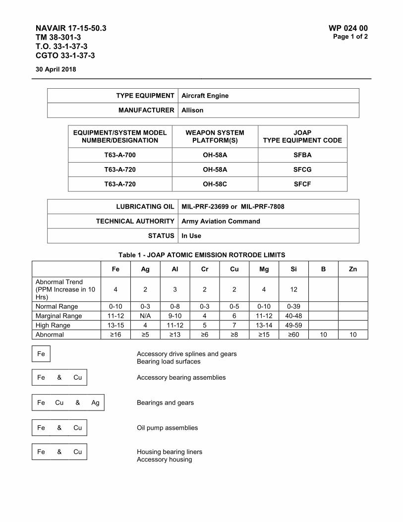
NAVAIR 17-15-50.3 TM 38-301-3 T.O. 33-1-37-3 CGTO 33-1-37-3
WP 024 00 Page 1 of 2
30 April 2018
TYPE EQUIPMENT Aircraft Engine
MANUFACTURER Allison
EQUIPMENT/SYSTEM MODEL NUMBER/DESIGNATION
WEAPON SYSTEM PLATFORM(S)
JOAP TYPE EQUIPMENT CODE
T63-A-700 OH-58A SFBA
T63-A-720 OH-58A SFCG
T63-A-720 OH-58C SFCF
LUBRICATING OIL MIL-PRF-23699 or MIL-PRF-7808
TECHNICAL AUTHORITY Army Aviation Command
STATUS In Use
Table 1 - JOAP ATOMIC EMISSION ROTRODE LIMITS
Fe Ag Al Cr Cu Mg Si B Zn
Abnormal Trend (PPM Increase in 10 Hrs)
4 2 3 2 2 4 12
Normal Range 0-10 0-3 0-8 0-3 0-5 0-10 0-39 Marginal Range 11-12 N/A 9-10 4 6 11-12 40-48 High Range 13-15 4 11-12 5 7 13-14 49-59 Abnormal ≥16 ≥5 ≥13 ≥6 ≥8 ≥15 ≥60 10 10
Fe Accessory drive splines and gears Bearing load surfaces
Fe & Cu Accessory bearing assemblies
Fe Cu & Ag Bearings and gears
Fe & Cu Oil pump assemblies
Fe & Cu Housing bearing liners Accessory housing

NAVAIR 17-15-50.3 TM 38-301-3 T.O. 33-1-37-3 CGTO 33-1-37-3
WP 024 00 Page 2 of 2
30 April 2018
Elevated boron (B) and/or zinc (Zn) concentrations usually indicate contamination with another oil type, primarily MIL-PRF-2104. Recommend resampling and retesting immediately. If new value exceeds 8.0 ppm, run check with D19-0 to ensure proper instrument function. When proper function is confirmed, report both results and suspected contamination with MIL-PRF-2104 to chain of command, maintenance chief, cognizant engineering authority (Army and Navy only), and other personnel as specified by local written procedures. Recommend flushing and retesting of contaminated pre-oilers, carts, or other reservoirs where contamination is found until both B and Zn concentrations fall below 8.0 ppm. Refer to JOAP Manual Volume 2, WP 021 00 for more information. Recommend segregation of confirmed or suspected contaminated stocks, and submit information (batch no., lot no., MIL-PRF, nature of problem, etc.) on such stocks through the Defense supply deficiency reporting system.
NOTES
Some older engines have a Ag cage and failure will show a continuing increase in Fe & Ag instead of Fe Cu & Ag.
High Si will show in the oil samples for the first for second oil changes on a new or overhauled engine.
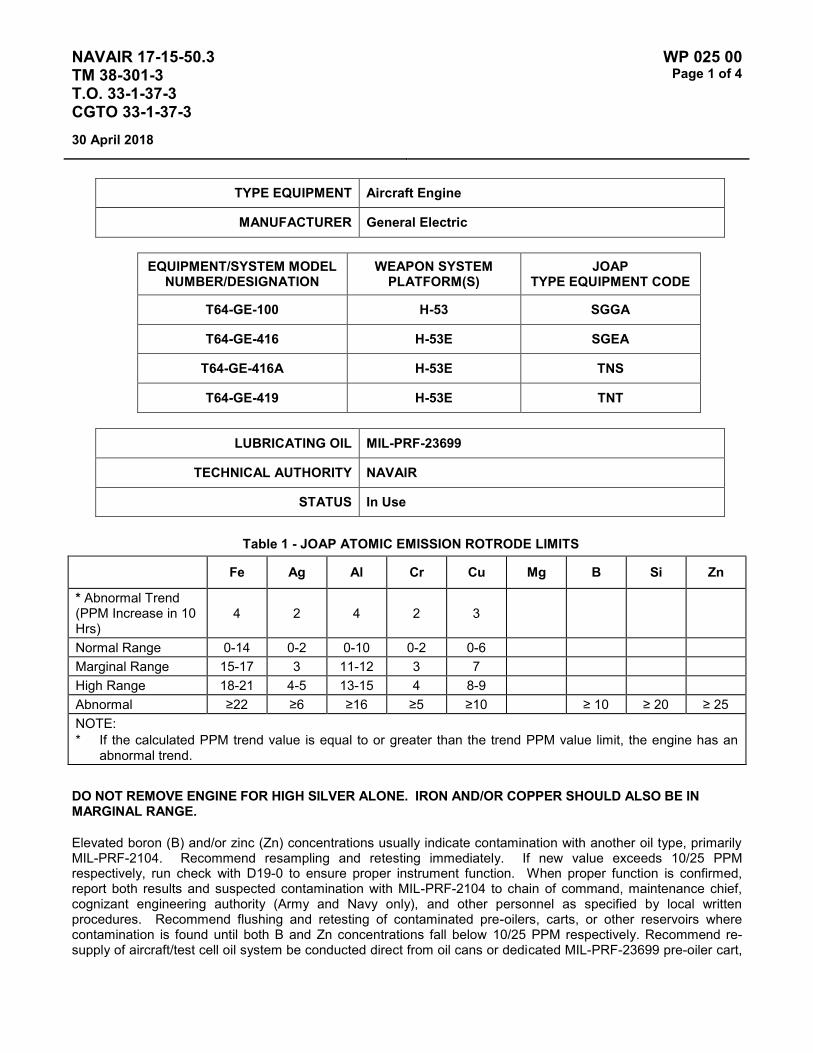
NAVAIR 17-15-50.3 TM 38-301-3 T.O. 33-1-37-3 CGTO 33-1-37-3
WP 025 00 Page 1 of 4
30 April 2018
TYPE EQUIPMENT Aircraft Engine
MANUFACTURER General Electric
EQUIPMENT/SYSTEM MODEL NUMBER/DESIGNATION
WEAPON SYSTEM PLATFORM(S)
JOAP TYPE EQUIPMENT CODE
T64-GE-100 H-53 SGGA
T64-GE-416 H-53E SGEA
T64-GE-416A H-53E TNS
T64-GE-419 H-53E TNT
LUBRICATING OIL MIL-PRF-23699
TECHNICAL AUTHORITY NAVAIR
STATUS In Use
Table 1 - JOAP ATOMIC EMISSION ROTRODE LIMITS
Fe Ag Al Cr Cu Mg B Si Zn
* Abnormal Trend (PPM Increase in 10 Hrs)
4 2 4 2 3
Normal Range 0-14 0-2 0-10 0-2 0-6 Marginal Range 15-17 3 11-12 3 7 High Range 18-21 4-5 13-15 4 8-9 Abnormal ≥22 ≥6 ≥16 ≥5 ≥10 ≥ 10 ≥ 20 ≥ 25 NOTE: * If the calculated PPM trend value is equal to or greater than the trend PPM value limit, the engine has an
abnormal trend.
DO NOT REMOVE ENGINE FOR HIGH SILVER ALONE. IRON AND/OR COPPER SHOULD ALSO BE IN MARGINAL RANGE.
Elevated boron (B) and/or zinc (Zn) concentrations usually indicate contamination with another oil type, primarily MIL-PRF-2104. Recommend resampling and retesting immediately. If new value exceeds 10/25 PPM respectively, run check with D19-0 to ensure proper instrument function. When proper function is confirmed, report both results and suspected contamination with MIL-PRF-2104 to chain of command, maintenance chief, cognizant engineering authority (Army and Navy only), and other personnel as specified by local written procedures. Recommend flushing and retesting of contaminated pre-oilers, carts, or other reservoirs where contamination is found until both B and Zn concentrations fall below 10/25 PPM respectively. Recommend re-supply of aircraft/test cell oil system be conducted direct from oil cans or dedicated MIL-PRF-23699 pre-oiler cart,

NAVAIR 17-15-50.3 TM 38-301-3 T.O. 33-1-37-3 CGTO 33-1-37-3
WP 025 00 Page 2 of 4
30 April 2018
or other reservoir. Refer to JOAP Manual Volume 2, WP 021 00 for more information. Recommend segregation of confirmed or suspected contaminated stocks, and submit information (batch no., lot no., MIL-PRF, nature of problem, etc.) on such stocks through the Defense supply deficiency reporting system.
Past contamination involving MIL-PRF-2104 due to zinc (Zn) on the T64 resulted in levels on the order of 100 ppm to 800 ppm. Contamination at this level over an extended period of time resulted in an increase in Silver (Ag). Contamination of this magnitude also requires flushing and retesting.
Elevated silicon (Si) concentration usually indicates contamination with soil, sand, or dust. If aluminum (Al) is also elevated, this suggests the presence of clay or soil. Recommend resampling and retesting immediately. If new value exceeds 20.0 PPM, run check with D19-0 to ensure proper instrument function. When proper function is confirmed, report both results and suspected contamination with soil, sand, or dust to chain of command, maintenance chief, cognizant engineering authority (Army and Navy only), and other personnel as specified by local written procedures. Recommend flushing and retesting of contaminated pre-oilers, carts, or other reservoirs where contamination is found until silicon concentration falls below 20.0 PPM. Refer to JOAP Manual Volume 2, WP 021 00 for more information. Recommend segregation of confirmed or suspected contaminated stocks, and submit information (batch no., lot no., MIL-PRF, nature of problem, etc.) on such stocks through the Defense supply deficiency reporting system.
Fe Main bearing balls, rollers and races, accessory gearbox gears and shafts, PTO gears
Fe Ag Accessory gearbox bearings
Fe Ag Power turbine shafts
Fe Ag Cu PTO bearings
Ag Cu Main bearing cages
Al Lube and scavenge oil pumps and thermal gradient housing
NOTE
Thermal gradient housing could be prime source of Al especially after heavy use of engine anti-icing system.
Consult NAVAIR 02B-105AJB-6-1 for additional information related to sources of wear metal contaminants in T64 engines.
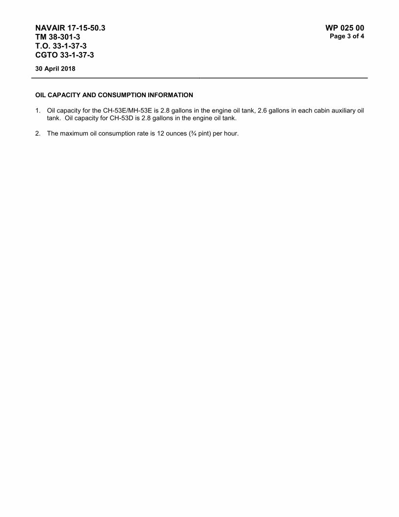
NAVAIR 17-15-50.3 TM 38-301-3 T.O. 33-1-37-3 CGTO 33-1-37-3
WP 025 00 Page 3 of 4
30 April 2018
OIL CAPACITY AND CONSUMPTION INFORMATION
1. Oil capacity for the CH-53E/MH-53E is 2.8 gallons in the engine oil tank, 2.6 gallons in each cabin auxiliary oil tank. Oil capacity for CH-53D is 2.8 gallons in the engine oil tank.
2. The maximum oil consumption rate is 12 ounces (¾ pint) per hour.

NAVAIR 17-15-50.3 TM 38-301-3 T.O. 33-1-37-3 CGTO 33-1-37-3
WP 025 00 Page 4 of 4
30 April 2018
This Page Intentionally left Blank

NAVAIR 17-15-50.3 TM 38-301-3 T.O. 33-1-37-3 CGTO 33-1-37-3
WP 026 00 Page 1 of 2
30 April 2018
TYPE EQUIPMENT Aircraft Engine
MANUFACTURER General Electric
EQUIPMENT/SYSTEM MODEL NUMBER/DESIGNATION
WEAPON SYSTEM PLATFORM(S)
JOAP TYPE EQUIPMENT CODE
T64-P4D C-27 SPLA
LUBRICATING OIL MIL-PRF-23699 or MIL-PRF-7808
TECHNICAL AUTHORITY Air Force
STATUS Aircraft and Engine Retired. WP retained for reference.
Table 1 - JOAP ATOMIC EMISSION ROTRODE LIMITS
Fe Ag Al Cr Cu Mg Na Ni Pb Si Sn Ti B Mo Zn B
* Abnormal Trend (PPM Increase in 10 Hrs)
4 2 4 2 3 6 4 4 10 10 10 4 4 4 4
Normal Range 0-14 0-2 0-10 0-2 0-6 0-7 0-6 0-6 0-14 0-14 0-12 0-6 0-6 0-6 0-6
Marginal Range 15-17 3 11-12 3 7 8 7 7 15-16 15-16 13-14 7 7 7 7
High Range 18-21 4-5 13-15 4 8-9 9 8 8 17-18 17-18 15-16 8 8 8 8 Abnormal ≥22 ≥6 ≥16 ≥5 ≥10 ≥10 ≥9 ≥9 ≥19 ≥19 ≥17 ≥9 ≥9 ≥9 ≥9 10 NOTE: * The value representing the PPM increase is the maximum allowable increase in an interval of 10 hours or less.
Elevated boron (B) and/or zinc (Zn) concentrations usually indicate contamination with another oil type, primarily MIL-PRF-2104. Recommend resampling and retesting immediately. If new value exceeds 8.0 PPM, run check with D19-0 to ensure proper instrument function. When proper function is confirmed, report both results and suspected contamination with MIL-PRF-2104 to chain of command, maintenance chief, cognizant engineering authority (Army and Navy only), and other personnel as specified by local written procedures. Recommend flushing and retesting of contaminated pre-oilers, carts, or other reservoirs where contamination is found until both B and Zn concentrations fall below 8.0 PPM. Refer to JOAP Manual Volume 2, WP 021 00 for more information. Recommend segregation of confirmed or suspected contaminated stocks, and submit information (batch no., lot no., MIL-PRF, nature of problem, etc.) on such stocks through the Defense supply deficiency reporting system.

NAVAIR 17-15-50.3 TM 38-301-3 T.O. 33-1-37-3 CGTO 33-1-37-3
WP 026 00 Page 2 of 2
30 April 2018
This Page Intentionally Left Blank
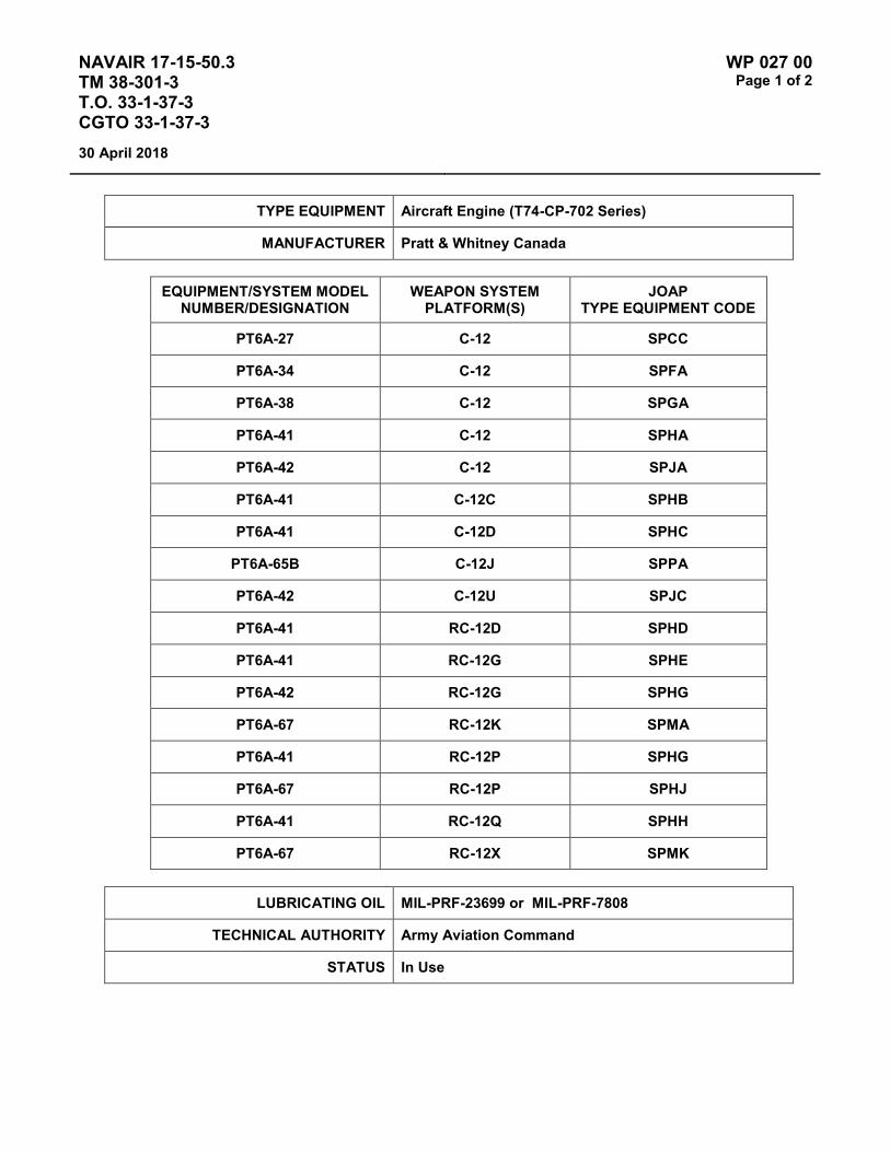
NAVAIR 17-15-50.3 TM 38-301-3 T.O. 33-1-37-3 CGTO 33-1-37-3
WP 027 00 Page 1 of 2
30 April 2018
TYPE EQUIPMENT Aircraft Engine (T74-CP-702 Series)
MANUFACTURER Pratt & Whitney Canada
EQUIPMENT/SYSTEM MODEL NUMBER/DESIGNATION
WEAPON SYSTEM PLATFORM(S)
JOAP TYPE EQUIPMENT CODE
PT6A-27 C-12 SPCC
PT6A-34 C-12 SPFA
PT6A-38 C-12 SPGA
PT6A-41 C-12 SPHA
PT6A-42 C-12 SPJA
PT6A-41 C-12C SPHB
PT6A-41 C-12D SPHC
PT6A-65B C-12J SPPA
PT6A-42 C-12U SPJC
PT6A-41 RC-12D SPHD
PT6A-41 RC-12G SPHE
PT6A-42 RC-12G SPHG
PT6A-67 RC-12K SPMA
PT6A-41 RC-12P SPHG
PT6A-67 RC-12P SPHJ
PT6A-41 RC-12Q SPHH
PT6A-67 RC-12X SPMK
LUBRICATING OIL MIL-PRF-23699 or MIL-PRF-7808
TECHNICAL AUTHORITY Army Aviation Command
STATUS In Use

NAVAIR 17-15-50.3 TM 38-301-3 T.O. 33-1-37-3 CGTO 33-1-37-3
WP 027 00 Page 2 of 2
30 April 2018
Table 1 - JOAP ATOMIC EMISSION ROTRODE LIMITS
Fe Ag Al Cr Cu Mg Si B Zn
Abnormal Trend (PPM Increase in 10 Hrs)
4 2 2 2 3 4 15
Normal Range 0-10 0-3 0-4 0-3 0-7 0-10 0-49 Marginal Range 11-12 N/A 5 4 8 11-12 50-60 High Range 13-14 4 6 5 9-10 13-14 61-74 Abnormal ≥15 ≥5 ≥7 ≥6 ≥11 ≥15 ≥75 10 10
Fe Accessory gears and splines Bearings, bearing load surfaces, bearing races
Fe & Cu Gears and bearing assemblies
Fe & Mg Housing and bearing liners
Fe Cu & Ag Main bearing
Fe Cu & Mg Accessory bushing in housing
Ag Bearing cages
Elevated boron (B) and/or zinc (Zn) concentrations usually indicate contamination with another oil type, primarily MIL-PRF-2104. Recommend resampling and retesting immediately. If new value exceeds 8.0 PPM, run check with D19-0 to ensure proper instrument function. When proper function is confirmed, report both results and suspected contamination with MIL-PRF-2104 to chain of command, maintenance chief, cognizant engineering authority (Army and Navy only), and other personnel as specified by local written procedures. Recommend flushing and retesting of contaminated pre-oilers, carts, or other reservoirs where contamination is found until both B and Zn concentrations fall below 8.0 PPM. Refer to JOAP Manual Volume 2, WP 021 00 for more information. Recommend segregation of confirmed or suspected contaminated stocks, and submit information (batch no., lot no., MIL-PRF, nature of problem, etc.) on such stocks through the Defense supply deficiency reporting system.
NOTES
High Si indicates contamination probably due to sand and dirt or silicon rubber parts. On infrequent occasions it could result from anti-foaming additive.
High Cu & Mg may be due to a bushing problem in the accessory housing.

NAVAIR 17-15-50.3 TM 38-301-3 T.O. 33-1-37-3 CGTO 33-1-37-3
WP 028 00 Page 1 of 2
30 April 2018
TYPE EQUIPMENT Aircraft Engine
MANUFACTURER Textron Lycoming
EQUIPMENT/SYSTEM MODEL NUMBER/DESIGNATION
WEAPON SYSTEM PLATFORM(S)
JOAP TYPE EQUIPMENT CODE
LTS-101-750A-1/B-2 HH-65A STAA
LUBRICATING OIL MIL-PRF-23699 or MIL-PRF-7808
TECHNICAL AUTHORITY US Coast Guard
STATUS In Use
Table 1 - JOAP ATOMIC EMISSION ROTRODE LIMITS
Fe Ag Al Cr Cu Mg B Si Zn
Abnormal Trend (PPM Increase in 10 Hrs)
3 3 3 3 3 3
Normal Range 0-3 0-2 0-4 0-2 0-2 0-4 Marginal Range 4 3 5-7 3 3 5-7 High Range 5 4 8-9 4 4 8-9 Abnormal ≥6 ≥5 ≥10 ≥5 ≥5 ≥10 10 10 10
Elevated boron (B) and/or zinc (Zn) concentrations usually indicate contamination with another oil type, primarily MIL-PRF-2104. Recommend resampling and retesting immediately. If new value exceeds 8.0 PPM, run check with D19-0 to ensure proper instrument function. When proper function is confirmed, report both results and suspected contamination with MIL-PRF-2104 to chain of command, maintenance chief, cognizant engineering authority (Army and Navy only), and other personnel as specified by local written procedures. Recommend flushing and retesting of contaminated pre-oilers, carts, or other reservoirs where contamination is found until both B and Zn concentrations fall below 8.0 PPM. Refer to JOAP Manual Volume 2, WP 021 00 for more information. Recommend segregation of confirmed or suspected contaminated stocks, and submit information (batch no., lot no., MIL-PRF, nature of problem, etc.) on such stocks through the Defense supply deficiency reporting system.

NAVAIR 17-15-50.3 TM 38-301-3 T.O. 33-1-37-3 CGTO 33-1-37-3
WP 028 00 Page 2 of 2
30 April 2018
Elevated silicon (Si) concentration usually indicates contamination with soil, sand, or dust. If aluminum (Al) is also elevated, this suggests the presence of clay or soil. Recommend resampling and retesting immediately. If new value exceeds 8.0 PPM, run check with D19-0 to ensure proper instrument function. When proper function is confirmed, report both results and suspected contamination with soil, sand, or dust to chain of command, maintenance chief, cognizant engineering authority (Army and Navy only), and other personnel as specified by local written procedures. Recommend flushing and retesting of contaminated pre-oilers, carts, or other reservoirs where contamination is found until silicon concentration falls below 8.0 PPM. Refer to JOAP Manual Volume 2, WP 021 00 for more information. Recommend segregation of confirmed or suspected contaminated stocks, and submit information (batch no., lot no., MIL-PRF, nature of problem, etc.) on such stocks through the Defense supply deficiency reporting system.
NOTES
Viscosity: Change oil if viscosity changes more than plus 25% or minus 10% of new oil viscosity
Water Limit: 0.100% or 1000 PPM
Fe Gears, bearings, bearing liners, oil pump or major support structures
Ag Bearing cages
Al Gearbox or inlet housing
Cr Power turbine shaft
Cu Bearing cages, oil pump

NAVAIR 17-15-50.3 TM 38-301-3 T.O. 33-1-37-3 CGTO 33-1-37-3
WP 029 00 Page 1 of 2
30 April 2018
TYPE EQUIPMENT Aircraft Engine
MANUFACTURER Pratt & Whitney Canada
EQUIPMENT/SYSTEM MODEL NUMBER/DESIGNATION
WEAPON SYSTEM PLATFORM(S)
JOAP TYPE EQUIPMENT CODE
T400-CP-400 H-1 SRAA
T400-CP-402 H-1 SRCA
T400-GE-401 VH-1N SRBB
T400-CP-400 UH-1N SRAB
LUBRICATING OIL MIL-PRF-23699 or MIL-PRF-7808
TECHNICAL AUTHORITY NAVAIR
STATUS Engine is not on a routine sampling program. WP is retain for reference.
Table 1 - JOAP ATOMIC EMISSION ROTRODE LIMITS
Fe Ag Al Cr Cu Mg B Si Zn
Abnormal Trend (PPM Increase in 10 Hrs)
4 3 3 2 2 2
Normal Range 0-10 0-2 0-6 0-2 0-5 0-3 Marginal Range 11-12 3-5 7 N/A 6 4 High Range 13-14 6-7 8-9 3 7 5 Abnormal ≥15 ≥8 ≥10 ≥4 ≥8 ≥6 10 10 10
Increases in Fe and Ag may be indicative of discrepancy in No. 5 bearing area if sample is taken from power section oil system. Increases in Fe in the third oil system may indicate a discrepancy in the clutch area.
Elevated boron (B) and/or zinc (Zn) concentrations usually indicate contamination with another oil type, primarily MIL-PRF-2104. Recommend resampling and retesting immediately. If new value exceeds 8.0 PPM, run check with D19-0 to ensure proper instrument function. When proper function is confirmed, report both results and suspected contamination with MIL-PRF-2104 to chain of command, maintenance chief, cognizant engineering authority (Army and Navy only), and other personnel as specified by local written procedures. Recommend flushing and retesting of contaminated pre-oilers, carts, or other reservoirs where contamination is found until both B and Zn concentrations fall below 8.0 PPM. Refer to JOAP Manual Volume 2, WP 021 00 for more information. Recommend segregation of confirmed or suspected contaminated stocks, and submit information (batch no., lot no., MIL-PRF, nature of problem, etc.) on such stocks through the Defense supply deficiency reporting system.

NAVAIR 17-15-50.3 TM 38-301-3 T.O. 33-1-37-3 CGTO 33-1-37-3
WP 029 00 Page 2 of 2
30 April 2018
Elevated silicon (Si) concentration usually indicates contamination with soil, sand, or dust. If aluminum (Al) is also elevated, this suggests the presence of clay or soil. Recommend resampling and retesting immediately. If new value exceeds 8.0 PPM, run check with D19-0 to ensure proper instrument function. When proper function is confirmed, report both results and suspected contamination with soil, sand, or dust to chain of command, maintenance chief, cognizant engineering authority (Army and Navy only), and other personnel as specified by local written procedures. Recommend flushing and retesting of contaminated pre-oilers, carts, or other reservoirs where contamination is found until silicon concentration falls below 8.0 PPM. Refer to JOAP Manual Volume 2, WP 021 00 for more information. Recommend segregation of confirmed or suspected contaminated stocks, and submit information (batch no., lot no., MIL-PRF, nature of problem, etc.) on such stocks through the Defense supply deficiency reporting system.
Fe Cr Power turbine rotor shaft, Nos. 1, 2, 3, and 4 bearing balls, rollers and races, compressor shaft, compressor air/oil seal, accessory gearbox bearing balls, rollers and races, reduction gearbox bearing balls, rollers and races.
Fe Ni Power turbine rotor shaft, compressor rotor shaft, air rotor seal, No. 1 bearing cage.
Fe Ni Cr Accessory gearbox gears and shafts, accessory gearbox oil pump gears and shafts, reduction gearbox gears and shafts, reduction gearbox oil pump gears and shafts.
Al Cu Mg Si Accessory gearbox housings, accessory gearbox oil pump housings, reduction gearbox housings, reduction gearbox oil pump housing and cover.
Cu Si Zn Fe Ag Nos. 2, 3, and 4 bearing cages, accessory gearbox bearing cages, reduction gearbox bearing cages.
Al Si Ni Cu Reduction gearbox sleeve bearings.
Al Cu Mg Reduction gearbox carrier oil seals.

NAVAIR 17-15-50.3 TM 38-301-3 T.O. 33-1-37-3 CGTO 33-1-37-3
WP 030 00 Page 1 of 2
30 April 2018
TYPE EQUIPMENT Aircraft Engine
MANUFACTURER Pratt & Whitney Canada
EQUIPMENT/SYSTEM MODEL NUMBER/DESIGNATION
WEAPON SYSTEM PLATFORM(S)
JOAP TYPE EQUIPMENT CODE
T400-CP-400 (Air Force) UH-1N SRAB
LUBRICATING OIL MIL-PRF-7808 or MIL-PRF-23699
TECHNICAL AUTHORITY Air Force
STATUS In Use
Table 1 - JOAP ATOMIC EMISSION ROTRODE LIMITS
Fe Ag Al Cr Cu Mg B Si Zn 1Abnormal Trend (PPM Increase in 10 Hrs)
4 3 3 2 2 2
Normal Range 0-2 0 0 0 0 0 Marginal Range 3-5 N/A 1 N/A 1 1 High Range 6-14 1-7 2-9 1-3 2-7 2-5 Abnormal ≥15 ≥8 ≥10 ≥4 ≥8 ≥6 10 10 10 1If the calculated PPM trend value is equal to or greater than the trend PPM value limit, the engine has an abnormal trend.
Increases in Fe and Ag may be indicative of discrepancy in No. 5 bearing area if sample is taken from power section oil system. Increases in Fe in the third oil system may indicate a discrepancy in the clutch area.
Elevated boron (B) and/or zinc (Zn) concentrations usually indicate contamination with another oil type, primarily MIL-PRF-2104. Recommend resampling and retesting immediately. If new value exceeds 8.0 PPM, run check with D19-0 to ensure proper instrument function. When proper function is confirmed, report both results and suspected contamination with MIL-PRF-2104 to chain of command, maintenance chief, cognizant engineering authority (Army and Navy only), and other personnel as specified by local written procedures. Recommend flushing and retesting of contaminated pre-oilers, carts, or other reservoirs where contamination is found until both B and Zn concentrations fall below 8.0 PPM. Refer to JOAP Manual Volume 2, WP 021 00 for more information. Recommend segregation of confirmed or suspected contaminated stocks, and submit information (batch no., lot no., MIL-PRF, nature of problem, etc.) on such stocks through the Defense supply deficiency reporting system.

NAVAIR 17-15-50.3 TM 38-301-3 T.O. 33-1-37-3 CGTO 33-1-37-3
WP 030 00 Page 2 of 2
30 April 2018
Elevated silicon (Si) concentration usually indicates contamination with soil, sand, or dust. If aluminum (Al) is also elevated, this suggests the presence of clay or soil. Recommend resampling and retesting immediately. If new value exceeds 8.0 PPM, run check with D19-0 to ensure proper instrument function. When proper function is confirmed, report both results and suspected contamination with soil, sand, or dust to chain of command, maintenance chief, cognizant engineering authority (Army and Navy only), and other personnel as specified by local written procedures. Recommend flushing and retesting of contaminated pre-oilers, carts, or other reservoirs where contamination is found until silicon concentration falls below 8.0 PPM. Refer to JOAP Manual Volume 2, WP 021 00 for more information. Recommend segregation of confirmed or suspected contaminated stocks, and submit information (batch no., lot no., MIL-PRF, nature of problem, etc.) on such stocks through the Defense supply deficiency reporting system.
Fe Cr Power turbine rotor shaft, Nos. 1, 2, 3, and 4 bearing balls, rollers and races, compressor shaft, compressor air/oil seal, accessory gearbox bearing balls, rollers and races, reduction gearbox bearing balls, rollers and races.
Fe Ni Power turbine rotor shaft, compressor rotor shaft, air rotor seal, No. 1 bearing cage.
Fe Ni Cr Accessory gearbox gears and shafts, accessory gearbox oil pump gears and shafts, reduction gearbox gears and shafts, reduction gearbox oil pump gears and shafts.
Al Cu Mg Si Accessory gearbox housings, accessory gearbox oil pump housings, reduction gearbox housings, reduction gearbox oil pump housing and cover.
Cu Si Zn Fe Ag Nos. 2, 3, and 4 bearing cages, accessory gearbox bearing cages, reduction gearbox bearing cages.
Al Si Ni Cu Reduction gearbox sleeve bearings.
Al Cu Mg Reduction gearbox carrier oil seals.
OIL CAPACITY AND CONSUMPTION INFORMATION
1. Oil capacity of the engine is 5 quarts. Ref. T.O. 1T-39A-2-1.
2. Allowable oil consumption rate (quantity per time) shall not exceed ¾ pint per hour (Ref T.O. 1T-39A-2-1).
3. Recommended engine oil consumption inspection interval: At 500-hour maintenance inspection or when engine is suspected of excessive oil usage.
4. Action to take if maximum oil consumption rate is exceeded: Identify/correct cause of high oil consumption.

NAVAIR 17-15-50.3 TM 38-301-3 T.O. 33-1-37-3 CGTO 33-1-37-3
WP 031 00 Page 1 of 2
30 April 2018
TYPE EQUIPMENT Aircraft Engine
MANUFACTURER Rolls-Royce
EQUIPMENT/SYSTEM MODEL NUMBER/DESIGNATION
WEAPON SYSTEM PLATFORM(S)
JOAP TYPE EQUIPMENT CODE
MK-529-8X (NASA) G-159 SQAA
LUBRICATING OIL MIL-PRF-7808 or MIL-PRF-23699
TECHNICAL AUTHORITY NASA
STATUS In Use
Table 1 - JOAP ATOMIC EMISSION ROTRODE LIMITS
Fe Ag Al Cr Cu Mg B Si Zn
Abnormal Trend (PPM Increase in 10 Hrs)
4 4 3 4
Normal Range 0-13 0-10 0-6 0-10 Marginal Range 14-16 11-12 7 11-12 High Range 17-19 13-14 8-9 13-14 Abnormal ≥20 ≥15 ≥10 ≥15 10 10 10
Elevated boron (B) and/or zinc (Zn) concentrations usually indicate contamination with another oil type, primarily MIL-PRF-2104. Recommend resampling and retesting immediately. If new value exceeds 8.0 PPM, run check with D19-0 to ensure proper instrument function. When proper function is confirmed, report both results and suspected contamination with MIL-PRF-2104 to chain of command, maintenance chief, cognizant engineering authority (Army and Navy only), and other personnel as specified by local written procedures. Recommend flushing and retesting of contaminated pre-oilers, carts, or other reservoirs where contamination is found until both B and Zn concentrations fall below 8.0 PPM. Refer to JOAP Manual Volume 2, WP 021 00 for more information. Recommend segregation of confirmed or suspected contaminated stocks, and submit information (batch no., lot no., MIL-PRF, nature of problem, etc.) on such stocks through the Defense supply deficiency reporting system.
Elevated silicon (Si) concentration usually indicates contamination with soil, sand, or dust. If aluminum (Al) is also elevated, this suggests the presence of clay or soil. Recommend resampling and retesting immediately. If new value exceeds 8.0 PPM, run check with D19-0 to ensure proper instrument function. When proper function is confirmed, report both results and suspected contamination with soil, sand, or dust to chain of command, maintenance chief, cognizant engineering authority (Army and Navy only), and other personnel as specified by local written procedures. Recommend flushing and retesting of contaminated pre-oilers, carts, or other reservoirs where contamination is found until silicon concentration falls below 8.0 PPM. Refer to JOAP Manual Volume 2, WP 021 00 for more information. Recommend segregation of confirmed or suspected contaminated stocks, and submit information (batch no., lot no., MIL-PRF, nature of problem, etc.) on such stocks through the Defense supply deficiency reporting system.

NAVAIR 17-15-50.3 TM 38-301-3 T.O. 33-1-37-3 CGTO 33-1-37-3
WP 031 00 Page 2 of 2
30 April 2018
This Page Intentionally Left Blank
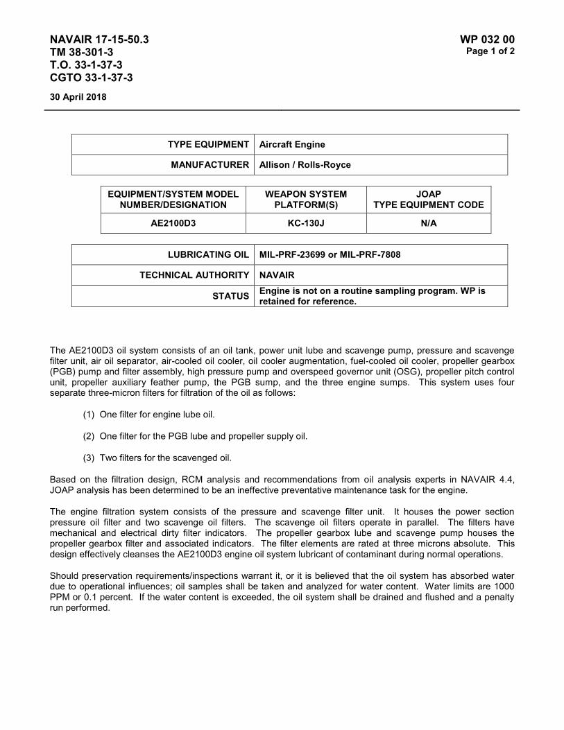
NAVAIR 17-15-50.3 TM 38-301-3 T.O. 33-1-37-3 CGTO 33-1-37-3
WP 032 00 Page 1 of 2
30 April 2018
TYPE EQUIPMENT Aircraft Engine
MANUFACTURER Allison / Rolls-Royce
EQUIPMENT/SYSTEM MODEL NUMBER/DESIGNATION
WEAPON SYSTEM PLATFORM(S)
JOAP TYPE EQUIPMENT CODE
AE2100D3 KC-130J N/A
LUBRICATING OIL MIL-PRF-23699 or MIL-PRF-7808
TECHNICAL AUTHORITY NAVAIR
STATUS Engine is not on a routine sampling program. WP is retained for reference.
The AE2100D3 oil system consists of an oil tank, power unit lube and scavenge pump, pressure and scavenge filter unit, air oil separator, air-cooled oil cooler, oil cooler augmentation, fuel-cooled oil cooler, propeller gearbox (PGB) pump and filter assembly, high pressure pump and overspeed governor unit (OSG), propeller pitch control unit, propeller auxiliary feather pump, the PGB sump, and the three engine sumps. This system uses four separate three-micron filters for filtration of the oil as follows:
(1) One filter for engine lube oil.
(2) One filter for the PGB lube and propeller supply oil.
(3) Two filters for the scavenged oil.
Based on the filtration design, RCM analysis and recommendations from oil analysis experts in NAVAIR 4.4, JOAP analysis has been determined to be an ineffective preventative maintenance task for the engine.
The engine filtration system consists of the pressure and scavenge filter unit. It houses the power section pressure oil filter and two scavenge oil filters. The scavenge oil filters operate in parallel. The filters have mechanical and electrical dirty filter indicators. The propeller gearbox lube and scavenge pump houses the propeller gearbox filter and associated indicators. The filter elements are rated at three microns absolute. This design effectively cleanses the AE2100D3 engine oil system lubricant of contaminant during normal operations.
Should preservation requirements/inspections warrant it, or it is believed that the oil system has absorbed water due to operational influences; oil samples shall be taken and analyzed for water content. Water limits are 1000 PPM or 0.1 percent. If the water content is exceeded, the oil system shall be drained and flushed and a penalty run performed.

NAVAIR 17-15-50.3 TM 38-301-3 T.O. 33-1-37-3 CGTO 33-1-37-3
WP 032 00 Page 2 of 2
30 April 2018
This Page Intentionally Left Blank
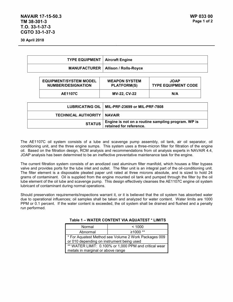
NAVAIR 17-15-50.3 TM 38-301-3 T.O. 33-1-37-3 CGTO 33-1-37-3
WP 033 00 Page 1 of 2
30 April 2018
TYPE EQUIPMENT Aircraft Engine
MANUFACTURER Allison / Rolls-Royce
EQUIPMENT/SYSTEM MODEL NUMBER/DESIGNATION
WEAPON SYSTEM PLATFORM(S)
JOAP TYPE EQUIPMENT CODE
AE1107C MV-22, CV-22 N/A
LUBRICATING OIL MIL-PRF-23699 or MIL-PRF-7808
TECHNICAL AUTHORITY NAVAIR
STATUS Engine is not on a routine sampling program. WP is retained for reference.
The AE1107C oil system consists of a lube and scavenge pump assembly, oil tank, air oil separator, oil conditioning unit, and the three engine sumps. This system uses a three-micron filter for filtration of the engine oil. Based on the filtration design, RCM analysis and recommendations from oil analysis experts in NAVAIR 4.4, JOAP analysis has been determined to be an ineffective preventative maintenance task for the engine.
The current filtration system consists of an anodized cast aluminum filter manifold, which houses a filter bypass valve and provides ports for the lube inlet and outlet. The filter unit is an integral part of the oil-conditioning unit. The filter element is a disposable pleated paper unit rated at three microns absolute, and is sized to hold 24 grams of contaminant. Oil is supplied from the engine mounted oil tank and pumped through the filter by the oil lube element of the oil lube and scavenge pump. This design effectively cleanses the AE1107C engine oil system lubricant of contaminant during normal operations.
Should preservation requirements/inspections warrant it, or it is believed that the oil system has absorbed water due to operational influences; oil samples shall be taken and analyzed for water content. Water limits are 1000 PPM or 0.1 percent. If the water content is exceeded, the oil system shall be drained and flushed and a penalty run performed.
Table 1 – WATER CONTENT VIA AQUATEST * LIMITS Normal < 1000
Abnormal ≥1000 ** * For Aquatest Method see Volume 2 Work Packages 009 or 010 depending on instrument being used ** WATER LIMIT: 0.100% or 1,000 PPM and critical wear metals in marginal or above range

NAVAIR 17-15-50.3 TM 38-301-3 T.O. 33-1-37-3 CGTO 33-1-37-3
WP 033 00 Page 2 of 2
30 April 2018
This Page Intentionally Left Blank

NAVAIR 17-15-50.3 TM 38-301-3 T.O. 33-1-37-3 CGTO 33-1-37-3
WP 034 00 Page 1 of 2
30 April 2018
TYPE EQUIPMENT Aircraft Engine
MANUFACTURER Pratt & Whitney
EQUIPMENT/SYSTEM MODEL NUMBER/DESIGNATION
WEAPON SYSTEM PLATFORM(S)
JOAP TYPE EQUIPMENT CODE
TF30-P-414A F-14A KAHA
LUBRICATING OIL MIL-PRF-23699 (or MIL-PRF-7808 for cold weather ops)
TECHNICAL AUTHORITY NAVAIR
STATUS Aircraft and Engine Retired – WP retained for reference.
Table 1 - JOAP ATOMIC EMISSION ROTRODE LIMITS
Fe Ag Al Cr Cu Mg Ni Ti B Si Zn
Abnormal Trend (PPM Increase in 10 Hrs)
4 3 3 3 4 3 4
Normal Range 0-16 6 0-3 0-6 0-16 0-6 0-11 Marginal Range 17-20 7-8 4 7 17-20 7 12-13 High Range 21-24 9 5 8-9 21-24 8-10 14-16 Abnormal ≥25 ≥10 ≥6 ≥10 ≥2 ≥11 ≥17 10 10 10
Teardown evaluations have identified the following areas to be most probable cause for certain wear metal indicators: Fe-main engine bearings, Mg-main gearbox, Ti-No. 2 bearing housing. Ag, Pb, Cu, Si individually are not cause for engine removal.
Elevated boron (B) and/or zinc (Zn) concentrations usually indicate contamination with another oil type, primarily MIL-PRF-2104. Recommend resampling and retesting immediately. If new value exceeds 8.0 PPM, run check with D19-0 to ensure proper instrument function. When proper function is confirmed, report both results and suspected contamination with MIL-PRF-2104 to chain of command, maintenance chief, cognizant engineering authority (Army and Navy only), and other personnel as specified by local written procedures. Recommend flushing and retesting of contaminated pre-oilers, carts, or other reservoirs where contamination is found until both B and Zn concentrations fall below 8.0 PPM. Refer to JOAP Manual Volume 2, WP 021 00 for more information. Recommend segregation of confirmed or suspected contaminated stocks, and submit information (batch no., lot no., MIL-PRF, nature of problem, etc.) on such stocks through the Defense supply deficiency reporting system.
Elevated silicon (Si) concentration usually indicates contamination with soil, sand, or dust. If aluminum (Al) is also elevated, this suggests the presence of clay or soil. Recommend resampling and retesting immediately. If new value exceeds 8.0 PPM, run check with D19-0 to ensure proper instrument function. When proper function is confirmed, report both results and suspected contamination with soil, sand, or dust to chain of command, maintenance chief, cognizant engineering authority (Army and Navy only), and other personnel as specified by local written procedures. Recommend flushing and retesting of contaminated pre-oilers, carts, or other reservoirs

NAVAIR 17-15-50.3 TM 38-301-3 T.O. 33-1-37-3 CGTO 33-1-37-3
WP 034 00 Page 2 of 2
30 April 2018
where contamination is found until silicon concentration falls below 8.0 PPM. Refer to JOAP Manual Volume 2, WP 021 00 for more information. Recommend segregation of confirmed or suspected contaminated stocks, and submit information (batch no., lot no., MIL-PRF, nature of problem, etc.) on such stocks through the Defense supply deficiency reporting system.
NOTE
Trend analysis is the best evaluation of engine condition. It is recommended that lab results be plotted on graphs to assist in evaluations. Engines which show no abnormal trend may reach the abnormal range until removal is recommended. Engines which show abnormal trend should be resampled for verification ASAP and evaluated using "Decision Making Guidance" table. Trend should always be based on PPM increase per 10 hour interval. Samples which show a significant drop in all wear metal (negative trend) should be resampled for verification ASAP and if confirmed a new oil baseline established by sampling every 5 hours for next 3 samples. Trend analysis done with less than 5 hours between samples are subject to error because the spectrometer tolerance of 1 PPM is averaged in the shorter time interval. Flushing oil system will not be accomplished unless an external contamination source can be identified.
Fe Main bearing ball/roller, races; Pump gears; Accessory drive shaft; Gearbox gears shaft and splines
Ag Cu Main, accessory, gearbox bearing cages
Al Gearbox oil pump housing; Nos. 4 and 5 scavenge pump housing
Fe Cr Nos. 2, 3, and 4 bearing seal plates
Mg No. 1 bearing housing; Gearbox housing
Ti Nos. 2 and 3 bearing support housing
Ti & Fe Cr Mo V Fan forward shaft spline wear or No. 1 or No. 2 bearing loose or fan forward shaft
Ni Nos. 4½ and 5 bearing seal liner No. 5 bearing compression springs

NAVAIR 17-15-50.3 TM 38-301-3 T.O. 33-1-37-3 CGTO 33-1-37-3
WP 035 00 Page 1 of 4
30 April 2018
TYPE EQUIPMENT Aircraft Engine
MANUFACTURER Pratt & Whitney
EQUIPMENT/SYSTEM MODEL NUMBER/DESIGNATION
WEAPON SYSTEM PLATFORM(S)
JOAP TYPE EQUIPMENT CODE
TF33-P-103 B-52 KCGA
LUBRICATING OIL MIL-PRF-7808
TECHNICAL AUTHORITY Air Force
STATUS In Use
Table 1 - JOAP ATOMIC EMISSION ROTRODE LIMITS
Fe Ag Al Cr Cu Mg Ti B Si Zn
* Abnormal Trend (PPM Increase in 10 Hrs)
8 2 2 3 2 5 3
Normal Range 0-3 0 0-2 0 0-1 0-1 0-2 Marginal Range 4-9 N/A 3 1 2 2 3 High Range 10-24 1 4 2 3 3 4 Abnormal ≥25 ≥2 ≥5 ≥3 ≥4 ≥4 ≥5 10 10 10 NOTE: * If the calculated PPM trend value is equal to or greater than the trend PPM value limit, the engine has an
abnormal trend.
Sudden increase in Mg indicates discrepancy in the accessory gearbox. All bearing journals except those that are titanium may be chrome plated during rework. Increases in titanium indicate bearing inner race turning on journal or hub.
Elevated boron (B) and/or zinc (Zn) concentrations usually indicate contamination with another oil type, primarily MIL-PRF-2104. Recommend resampling and retesting immediately. If new value exceeds 8.0 PPM, run check with D19-0 to ensure proper instrument function. When proper function is confirmed, report both results and suspected contamination with MIL-PRF-2104 to chain of command, maintenance chief, cognizant engineering authority (Army and Navy only), and other personnel as specified by local written procedures. Recommend flushing and retesting of contaminated pre-oilers, carts, or other reservoirs where contamination is found until both B and Zn concentrations fall below 8.0 PPM. Refer to JOAP Manual Volume 2, WP 021 00 for more information. Recommend segregation of confirmed or suspected contaminated stocks, and submit information (batch no., lot no., MIL-PRF, nature of problem, etc.) on such stocks through the Defense supply deficiency reporting system.

NAVAIR 17-15-50.3 TM 38-301-3 T.O. 33-1-37-3 CGTO 33-1-37-3
WP 035 00 Page 2 of 4
30 April 2018
Elevated silicon (Si) concentration usually indicates contamination with soil, sand, or dust. If aluminum (Al) is also elevated, this suggests the presence of clay or soil. Recommend resampling and retesting immediately. If new value exceeds 8.0 PPM, run check with D19-0 to ensure proper instrument function. When proper function is confirmed, report both results and suspected contamination with soil, sand, or dust to chain of command, maintenance chief, cognizant engineering authority (Army and Navy only), and other personnel as specified by local written procedures. Recommend flushing and retesting of contaminated pre-oilers, carts, or other reservoirs where contamination is found until silicon concentration falls below 8.0 PPM. Refer to JOAP Manual Volume 2, WP 021 00 for more information. Recommend segregation of confirmed or suspected contaminated stocks, and submit information (batch no., lot no., MIL-PRF, nature of problem, etc.) on such stocks through the Defense supply deficiency reporting system.
NOTES
TF33 engines that have experienced a rise in magnesium only may be returned to service after accomplishing the following procedures:
1. Establish that magnesium is the only metal that is experiencing an increase (Si does not apply to this). Most likely cause is oil relief valve rubbing. Shim is available to stop valve contact to eliminate the need for the following, recurring drain and flush.
2. Drain all oil (main) from the engine.
3. Inspect oil filter and sump screen for contaminants.
4. Inspect the front gearbox assembly (front door) for any signs of abnormal wear.
5. If the above procedures check ok, then fill the engine with oil and perform a run to reestablish the baseline.
6. Take a JOAP sample and if limits fall within parameters, the engine may be returned to service.
7. A follow-up JOAP must be taken after the first five hours of engine operation.
8. Follow any command guidance in reporting high magnesium occurrence.
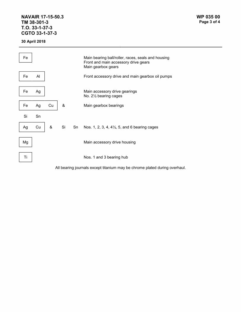
NAVAIR 17-15-50.3 TM 38-301-3 T.O. 33-1-37-3 CGTO 33-1-37-3
WP 035 00 Page 3 of 4
30 April 2018
Fe Main bearing ball/roller, races, seals and housing Front and main accessory drive gears Main gearbox gears
Fe Al Front accessory drive and main gearbox oil pumps
Fe Ag Main accessory drive gearings No. 2½ bearing cages
Fe Ag Cu & Main gearbox bearings
Si Sn
Ag Cu & Si Sn Nos. 1, 2, 3, 4, 4½, 5, and 6 bearing cages
Mg Main accessory drive housing
Ti Nos. 1 and 3 bearing hub
All bearing journals except titanium may be chrome plated during overhaul.

NAVAIR 17-15-50.3 TM 38-301-3 T.O. 33-1-37-3 CGTO 33-1-37-3
WP 035 00 Page 4 of 4
30 April 2018
This Page Intentionally Left Blank

NAVAIR 17-15-50.3 TM 38-301-3 T.O. 33-1-37-3 CGTO 33-1-37-3
WP 036 00 Page 1 of 4
30 April 2018
TYPE EQUIPMENT Aircraft Engine
MANUFACTURER Pratt & Whitney
EQUIPMENT/SYSTEM MODEL NUMBER/DESIGNATION
WEAPON SYSTEM PLATFORM(S)
JOAP TYPE EQUIPMENT CODE
TF33-PW-102 C-135 KCFA
TF33-PW-102 / JT3D-3B E-8 KCFD
LUBRICATING OIL MIL-PRF-7808
TECHNICAL AUTHORITY Air Force
STATUS In Use
Table 1 - JOAP ATOMIC EMISSION ROTRODE LIMITS
Fe Ag Al Cr Cu Mg Ti B Si Zn
* Abnormal Trend (PPM Increase in 10 Hrs)
4 2 2 3 2 2 3
Normal Range 0-2 0-1 0-1 0-1 0-1 0-1 0-2 Marginal Range 3-9 N/A 2-3 2 2 2 3 High Range 10-24 2 4 3 3 3 4 Abnormal ≥25 ≥3 ≥5 ≥4 ≥4 ≥4 ≥5 10 10 10 NOTE: * If the calculated PPM trend value is equal to or greater than the trend PPM value limit, the engine has an
abnormal trend.
Sudden increase in Mg indicates discrepancy in the accessory gearbox. All bearing journals except those that are titanium may be chrome plated during rework. Increases in titanium indicate bearing inner race turning on journal or hub.
Elevated boron (B) and/or zinc (Zn) concentrations usually indicate contamination with another oil type, primarily MIL-PRF-2104. Recommend resampling and retesting immediately. If new value exceeds 8.0 PPM, run check with D19-0 to ensure proper instrument function. When proper function is confirmed, report both results and suspected contamination with MIL-PRF-2104 to chain of command, maintenance chief, cognizant engineering authority (Army and Navy only), and other personnel as specified by local written procedures. Recommend flushing and retesting of contaminated pre-oilers, carts, or other reservoirs where contamination is found until both B and Zn concentrations fall below 8.0 PPM. Refer to JOAP Manual Volume 2, WP 021 00 for more information. Recommend segregation of confirmed or suspected contaminated stocks, and submit information (batch no., lot no., MIL-PRF, nature of problem, etc.) on such stocks through the Defense supply deficiency reporting system.

NAVAIR 17-15-50.3 TM 38-301-3 T.O. 33-1-37-3 CGTO 33-1-37-3
WP 036 00 Page 2 of 4
30 April 2018
Elevated silicon (Si) concentration usually indicates contamination with soil, sand, or dust. If aluminum (Al) is also elevated, this suggests the presence of clay or soil. Recommend resampling and retesting immediately. If new value exceeds 8.0 PPM, run check with D19-0 to ensure proper instrument function. When proper function is confirmed, report both results and suspected contamination with soil, sand, or dust to chain of command, maintenance chief, cognizant engineering authority (Army and Navy only), and other personnel as specified by local written procedures. Recommend flushing and retesting of contaminated pre-oilers, carts, or other reservoirs where contamination is found until silicon concentration falls below 8.0 PPM. Refer to JOAP Manual Volume 2, WP 021 00 for more information. Recommend segregation of confirmed or suspected contaminated stocks, and submit information (batch no., lot no., MIL-PRF, nature of problem, etc.) on such stocks through the Defense supply deficiency reporting system.
NOTES
TF33 engines that have experienced a rise in magnesium only may be returned to service after accomplishing the following procedures:
1. Establish that magnesium is the only metal that is experiencing an increase (Si does not apply to this). Most likely cause is oil relief valve rubbing. Shim is available to stop valve contact to eliminate the need for the following, recurring drain and flush.
2. Drain all oil (main) from the engine.
3. Inspect oil filter and sump screen for contaminants.
4. Inspect the front gearbox assembly (front door) for any signs of abnormal wear.
5. If the above procedures check ok, then fill the engine with oil and perform a run to reestablish the baseline.
6. Take a JOAP sample and if limits fall within parameters, the engine may be returned to service.
7. A follow-up JOAP must be taken after the first five hours of engine operation.
8. Follow any command guidance in reporting high magnesium occurrence.

NAVAIR 17-15-50.3 TM 38-301-3 T.O. 33-1-37-3 CGTO 33-1-37-3
WP 036 00 Page 3 of 4
30 April 2018
Fe Main bearing ball/roller, races, seals and housing Front and main accessory drive gears Main gearbox gears
Fe Al Front accessory drive and main gearbox oil pumps
Fe Ag Main accessory drive gearings No. 2½ bearing cages
Fe Ag Cu & Main gearbox bearings
Si Sn
Ag Cu & Si Sn Nos. 1, 2, 3, 4, 4½, 5 and 6 bearing cages
Mg Main accessory drive housing
Ti Nos. 1 and 3 bearing hub
All bearing journals except titanium may be chrome plated during overhaul.

NAVAIR 17-15-50.3 TM 38-301-3 T.O. 33-1-37-3 CGTO 33-1-37-3
WP 036 00 Page 4 of 4
30 April 2018
This Page Intentionally Left Blank

NAVAIR 17-15-50.3 TM 38-301-3 T.O. 33-1-37-3 CGTO 33-1-37-3
WP 037 00 Page 1 of 4
30 April 2018
TYPE EQUIPMENT Aircraft Engine
MANUFACTURER Pratt & Whitney
EQUIPMENT/SYSTEM MODEL NUMBER/DESIGNATION
WEAPON SYSTEM PLATFORM(S)
JOAP TYPE EQUIPMENT CODE
TF33-P-5 C-135 KCBA
TF33-P-9 E-8 KCDC
LUBRICATING OIL MIL-PRF-7808
TECHNICAL AUTHORITY Air Force
STATUS In Use
Table 1 - JOAP ATOMIC EMISSION ROTRODE LIMITS
Fe Ag Al Cr Cu Mg Ti B Si Zn
* Abnormal Trend (PPM Increase in 10 Hrs)
8 2 2 3 2 5 3
Normal Range 0-19 0-1 0-1 0-5 0-1 0-5 0-2 Marginal Range 20-37 N/A 2-5 6-7 2 6-18 3-4 High Range 38-49 2 6 8-9 3 19 5 Abnormal ≥50 ≥3 ≥7 ≥10 ≥4 ≥20 ≥6 10 10 10 NOTES: * If the calculated PPM trend value is equal to or greater than the trend PPM value limit, the engine has an
abnormal trend.
Sudden increase in Mg indicates discrepancy in the accessory gearbox. All bearing journals except those that are titanium may be chrome plated during rework. Increases in titanium indicate bearing inner race turning on journal or hub.
Elevated boron (B) and/or zinc (Zn) concentrations usually indicate contamination with another oil type, primarily MIL-PRF-2104. Recommend resampling and retesting immediately. If new value exceeds 8.0 PPM, run check with D19-0 to ensure proper instrument function. When proper function is confirmed, report both results and suspected contamination with MIL-PRF-2104 to chain of command, maintenance chief, cognizant engineering authority (Army and Navy only), and other personnel as specified by local written procedures. Recommend flushing and retesting of contaminated pre-oilers, carts, or other reservoirs where contamination is found until both B and Zn concentrations fall below 8.0 PPM. Refer to JOAP Manual Volume 2, WP 021 00 for more information. Recommend segregation of confirmed or suspected contaminated stocks, and submit information (batch no., lot no., MIL-PRF, nature of problem, etc.) on such stocks through the Defense supply deficiency reporting system.

NAVAIR 17-15-50.3 TM 38-301-3 T.O. 33-1-37-3 CGTO 33-1-37-3
WP 037 00 Page 2 of 4
30 April 2018
Elevated silicon (Si) concentration usually indicates contamination with soil, sand, or dust. If aluminum (Al) is also elevated, this suggests the presence of clay or soil. Recommend resampling and retesting immediately. If new value exceeds 8.0 PPM, run check with D19-0 to ensure proper instrument function. When proper function is confirmed, report both results and suspected contamination with soil, sand, or dust to chain of command, maintenance chief, cognizant engineering authority (Army and Navy only), and other personnel as specified by local written procedures. Recommend flushing and retesting of contaminated pre-oilers, carts, or other reservoirs where contamination is found until silicon concentration falls below 8.0 PPM. Refer to JOAP Manual Volume 2, WP 021 00 for more information. Recommend segregation of confirmed or suspected contaminated stocks, and submit information (batch no., lot no., MIL-PRF, nature of problem, etc.) on such stocks through the Defense supply deficiency reporting system.
NOTES
TF33 engines that have experienced a rise in magnesium only may be returned to service after accomplishing the following procedures:
1. Establish that magnesium is the only metal that is experiencing an increase (Si does not apply to this). Most likely cause is oil relief valve rubbing. Shim is available to stop valve contact to eliminate the need for the following, recurring drain and flush.
2. Drain all oil (main) from the engine.
3. Inspect oil filter and sump screen for contaminants.
4. Inspect the front gearbox assembly (front door) for any signs of abnormal wear.
5. If the above procedures check ok, then fill the engine with oil and perform a run to reestablish the baseline.
6. Take a JOAP sample and if limits fall within parameters, the engine may be returned to service.
7. A follow-up JOAP must be taken after the first five hours of engine operation.
8. Follow any command guidance in reporting high magnesium occurrence.

NAVAIR 17-15-50.3 TM 38-301-3 T.O. 33-1-37-3 CGTO 33-1-37-3
WP 037 00 Page 3 of 4
30 April 2018
Fe Main bearing ball/roller, races, seals and housing Front and main accessory drive gears Main gearbox gears
Fe Al Front accessory drive and main gearbox oil pumps
Fe Ag Main accessory drive gearings No. 2½ bearing cages
Fe Ag Cu & Si Sn Main gearbox bearings
Si Sn
Ag Cu & Si Sn Nos. 1, 2, 3, 4, 4½, 5, and 6 bearing cages
Mg Main accessory drive housing
Ti Nos. 1 and 3 bearing hub
All bearing journals except titanium may be chrome plated during overhaul.

NAVAIR 17-15-50.3 TM 38-301-3 T.O. 33-1-37-3 CGTO 33-1-37-3
WP 037 00 Page 4 of 4
30 April 2018
This Page Intentionally Left Blank

NAVAIR 17-15-50.3 TM 38-301-3 T.O. 33-1-37-3 CGTO 33-1-37-3
WP 038 00 Page 1 of 4
30 April 2018
TYPE EQUIPMENT Aircraft Engine
MANUFACTURER Pratt & Whitney
EQUIPMENT/SYSTEM MODEL NUMBER/DESIGNATION
WEAPON SYSTEM PLATFORM(S)
JOAP TYPE EQUIPMENT CODE
TF33-P-7 C-141 KCCA
LUBRICATING OIL MIL-PRF-7808
TECHNICAL AUTHORITY Air Force
STATUS Aircraft and Engines Retired. WP retained for reference.
Table 1 - JOAP ATOMIC EMISSION ROTRODE LIMITS
Fe Ag Al Cr Cu Mg Ti B Si Zn
* Abnormal Trend (PPM Increase in 10 Hrs)
6 2 2 2 2 4 3
Normal Range 0-8 0-1 0-1 0-1 0-1 0-4 0-2 Marginal Range 9-21 N/A 2-3 2-3 2-3 5-6 3-4 High Range 22-31 2 4 4 4 7 5 Abnormal ≥32 ≥3 ≥5 ≥5 ≥5 ≥8 ≥6 10 10 10 NOTE: * If the calculated PPM trend value is equal to or greater than the trend PPM value limit, the engine has an
abnormal trend.
Sudden increase in Mg indicates discrepancy in the accessory gearbox. All bearing journals except those that are titanium may be chrome plated during rework. Increases in titanium indicate bearing inner race turning on journal or hub.
Elevated boron (B) and/or zinc (Zn) concentrations usually indicate contamination with another oil type, primarily MIL-PRF-2104. Recommend resampling and retesting immediately. If new value exceeds 8.0 PPM, run check with D19-0 to ensure proper instrument function. When proper function is confirmed, report both results and suspected contamination with MIL-PRF-2104 to chain of command, maintenance chief, cognizant engineering authority (Army and Navy only), and other personnel as specified by local written procedures. Recommend flushing and retesting of contaminated pre-oilers, carts, or other reservoirs where contamination is found until both B and Zn concentrations fall below 8.0 PPM. Refer to JOAP Manual Volume 2, WP 021 00 for more information. Recommend segregation of confirmed or suspected contaminated stocks, and submit information (batch no., lot no., MIL-PRF, nature of problem, etc.) on such stocks through the Defense supply deficiency reporting system.

NAVAIR 17-15-50.3 TM 38-301-3 T.O. 33-1-37-3 CGTO 33-1-37-3
WP 038 00 Page 2 of 4
30 April 2018
Elevated silicon (Si) concentration usually indicates contamination with soil, sand, or dust. If aluminum (Al) is also elevated, this suggests the presence of clay or soil. Recommend resampling and retesting immediately. If new value exceeds 8.0 PPM, run check with D19-0 to ensure proper instrument function. When proper function is confirmed, report both results and suspected contamination with soil, sand, or dust to chain of command, maintenance chief, cognizant engineering authority (Army and Navy only), and other personnel as specified by local written procedures. Recommend flushing and retesting of contaminated pre-oilers, carts, or other reservoirs where contamination is found until silicon concentration falls below 8.0 PPM. Refer to JOAP Manual Volume 2, WP 021 00 for more information. Recommend segregation of confirmed or suspected contaminated stocks, and submit information (batch no., lot no., MIL-PRF, nature of problem, etc.) on such stocks through the Defense supply deficiency reporting system.
NOTES
TF33 engines that have experienced a rise in magnesium only may be returned to service after accomplishing the following procedures:
1. Establish that magnesium is the only metal that is experiencing an increase (Si does not apply to this). Most likely cause is oil relief valve rubbing. Shim is available to stop valve contact to eliminate the need for the following, recurring drain and flush.
2. Drain all oil (main) from the engine.
3. Inspect oil filter and sump screen for contaminants.
4. Inspect the front gearbox assembly (front door) for any signs of abnormal wear.
5. If the above procedures check ok, then fill the engine with oil and perform a run to reestablish the baseline.
6. Take a JOAP sample and if limits fall within parameters, the engine may be returned to service.
7. A follow-up JOAP must be taken after the first five hours of engine operation.
8. Follow any command guidance in reporting high magnesium occurrence.

NAVAIR 17-15-50.3 TM 38-301-3 T.O. 33-1-37-3 CGTO 33-1-37-3
WP 038 00 Page 3 of 4
30 April 2018
Fe Main bearing ball/roller, races, seals and housing Front and main accessory drive gears Main gearbox gears
Fe Al Front accessory drive and main gearbox oil pumps
Fe Ag Main accessory drive gearings No. 2½ bearing cages
Fe Ag Cu & Si Sn Main gearbox bearings
Si Sn
Ag Cu & Si Sn Nos. 1, 2, 3, 4, 4½, 5, and 6 bearing cages
Mg Main accessory drive housing
Ti Nos. 1 and 3 bearing hub
All bearing journals except titanium may be chrome plated during overhaul.

NAVAIR 17-15-50.3 TM 38-301-3 T.O. 33-1-37-3 CGTO 33-1-37-3
WP 038 00 Page 4 of 4
30 April 2018
This Page Intentionally Left Blank
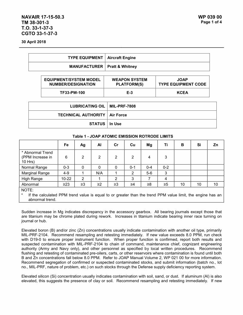
NAVAIR 17-15-50.3 TM 38-301-3 T.O. 33-1-37-3 CGTO 33-1-37-3
WP 039 00 Page 1 of 4
30 April 2018
TYPE EQUIPMENT Aircraft Engine
MANUFACTURER Pratt & Whitney
EQUIPMENT/SYSTEM MODEL NUMBER/DESIGNATION
WEAPON SYSTEM PLATFORM(S)
JOAP TYPE EQUIPMENT CODE
TF33-PW-100 E-3 KCEA
LUBRICATING OIL MIL-PRF-7808
TECHNICAL AUTHORITY Air Force
STATUS In Use
Table 1 - JOAP ATOMIC EMISSION ROTRODE LIMITS
Fe Ag Al Cr Cu Mg Ti B Si Zn
* Abnormal Trend (PPM Increase in 10 Hrs)
6 2 2 2 2 4 3
Normal Range 0-3 0 0 0 0-1 0-4 0-2 Marginal Range 4-9 1 N/A 1 2 5-6 3 High Range 10-22 2 1 2 3 7 4 Abnormal ≥23 ≥3 ≥2 ≥3 ≥4 ≥8 ≥5 10 10 10 NOTE: * If the calculated PPM trend value is equal to or greater than the trend PPM value limit, the engine has an
abnormal trend.
Sudden increase in Mg indicates discrepancy in the accessory gearbox. All bearing journals except those that are titanium may be chrome plated during rework. Increases in titanium indicate bearing inner race turning on journal or hub.
Elevated boron (B) and/or zinc (Zn) concentrations usually indicate contamination with another oil type, primarily MIL-PRF-2104. Recommend resampling and retesting immediately. If new value exceeds 8.0 PPM, run check with D19-0 to ensure proper instrument function. When proper function is confirmed, report both results and suspected contamination with MIL-PRF-2104 to chain of command, maintenance chief, cognizant engineering authority (Army and Navy only), and other personnel as specified by local written procedures. Recommend flushing and retesting of contaminated pre-oilers, carts, or other reservoirs where contamination is found until both B and Zn concentrations fall below 8.0 PPM. Refer to JOAP Manual Volume 2, WP 021 00 for more information. Recommend segregation of confirmed or suspected contaminated stocks, and submit information (batch no., lot no., MIL-PRF, nature of problem, etc.) on such stocks through the Defense supply deficiency reporting system.
Elevated silicon (Si) concentration usually indicates contamination with soil, sand, or dust. If aluminum (Al) is also elevated, this suggests the presence of clay or soil. Recommend resampling and retesting immediately. If new

NAVAIR 17-15-50.3 TM 38-301-3 T.O. 33-1-37-3 CGTO 33-1-37-3
WP 039 00 Page 2 of 4
30 April 2018
value exceeds 8.0 PPM, run check with D19-0 to ensure proper instrument function. When proper function is confirmed, report both results and suspected contamination with soil, sand, or dust to chain of command, maintenance chief, cognizant engineering authority (Army and Navy only), and other personnel as specified by local written procedures. Recommend flushing and retesting of contaminated pre-oilers, carts, or other reservoirs where contamination is found until silicon concentration falls below 8.0 PPM. Refer to JOAP Manual Volume 2, WP 021 00 for more information. Recommend segregation of confirmed or suspected contaminated stocks, and submit information (batch no., lot no., MIL-PRF, nature of problem, etc.) on such stocks through the Defense supply deficiency reporting system.
NOTES
TF33 engines that have experienced a rise in magnesium only may be returned to service after accomplishing the following procedures:
1. Establish that magnesium is the only metal that is experiencing an increase (Si does not apply to this). Most likely cause is oil relief valve rubbing. Shim is available to stop valve contact to eliminate the need for the following, recurring drain and flush.
2. Drain all oil (main) from the engine.
3. Inspect oil filter and sump screen for contaminants.
4. Inspect the front gearbox assembly (front door) for any signs of abnormal wear.
5. If the above procedures check ok, then fill the engine with oil and perform a run to reestablish the baseline.
6. Take a JOAP sample and if limits fall within parameters, the engine may be returned to service.
7. A follow-up JOAP must be taken after the first five hours of engine operation.
8. Follow any command guidance in reporting high magnesium occurrence.
Fe Main bearing ball/roller, races; seals and housing Front and main accessory drive gears Main gearbox gears
Fe Al Front accessory drive and main gearbox oil pumps
Fe Ag Main accessory drive gearings No. 2, 3, 4, 4½, 5, and 6 bearing cages
Fe Ag Cu & Main gearbox bearings

NAVAIR 17-15-50.3 TM 38-301-3 T.O. 33-1-37-3 CGTO 33-1-37-3
WP 039 00 Page 3 of 4
30 April 2018
Si Sn
Ag Cu & Si Sn Nos. 1and 2½ bearing cages
Mg Main accessory drive housing
Ti Nos. 1 and 3 bearing hub
NOTE
All bearing journals except titanium may be chrome plated during overhaul.

NAVAIR 17-15-50.3 TM 38-301-3 T.O. 33-1-37-3 CGTO 33-1-37-3
WP 039 00 Page 4 of 4
30 April 2018
This Page Intentionally Left Blank

NAVAIR 17-15-50.3 TM 38-301-3 T.O. 33-1-37-3 CGTO 33-1-37-3
WP 040 00 Page 1 of 4
30 April 2018
TYPE EQUIPMENT Aircraft Engine
MANUFACTURER General Electric
EQUIPMENT/SYSTEM MODEL NUMBER/DESIGNATION
WEAPON SYSTEM PLATFORM(S)
JOAP TYPE EQUIPMENT CODE
TF34-GE-100 A-10 KDAA
LUBRICATING OIL MIL-PRF-7808
TECHNICAL AUTHORITY Air Force
STATUS In Use
Table 1 - JOAP ATOMIC EMISSION ROTRODE LIMITS
** Fe *** Ag Al Cr Cu Mg Ni Ti B Si Zn
* Abnormal Trend (PPM Increase in 10 Hrs)
4 2 2 2 3 2 2
Normal Range 0-2 0 0 0 0 0 0-2 Marginal Range 3-6 N/A N/A 1 1 1 N/A High Range 7-17 1-5 1-5 2-4 2-13 2-6 3-4 Abnormal ≥18 ≥6 ≥6 ≥5 ≥14 ≥7 ≥5 10 10 10 NOTES: * If the calculated PPM trend value is equal to or greater than the trend PPM value limit, the engine has an
abnormal trend. ** See notes on next page. *** High Ag by itself is not cause for rejection of the engine.
Elevated boron (B) and/or zinc (Zn) concentrations usually indicate contamination with another oil type, primarily MIL-PRF-2104. Recommend resampling and retesting immediately. If new value exceeds 8.0 PPM, run check with D19-0 to ensure proper instrument function. When proper function is confirmed, report both results and suspected contamination with MIL-PRF-2104 to chain of command, maintenance chief, cognizant engineering authority (Army and Navy only), and other personnel as specified by local written procedures. Recommend flushing and retesting of contaminated pre-oilers, carts, or other reservoirs where contamination is found until both B and Zn concentrations fall below 8.0 PPM. Refer to JOAP Manual Volume 2, WP 021 00 for more information. Recommend segregation of confirmed or suspected contaminated stocks, and submit information (batch no., lot no., MIL-PRF, nature of problem, etc.) on such stocks through the Defense supply deficiency reporting system.
Elevated silicon (Si) concentration usually indicates contamination with soil, sand, or dust. If aluminum (Al) is also elevated, this suggests the presence of clay or soil. Recommend resampling and retesting immediately. If new value exceeds 8.0 PPM, run check with D19-0 to ensure proper instrument function. When proper function is confirmed, report both results and suspected contamination with soil, sand, or dust to chain of command,
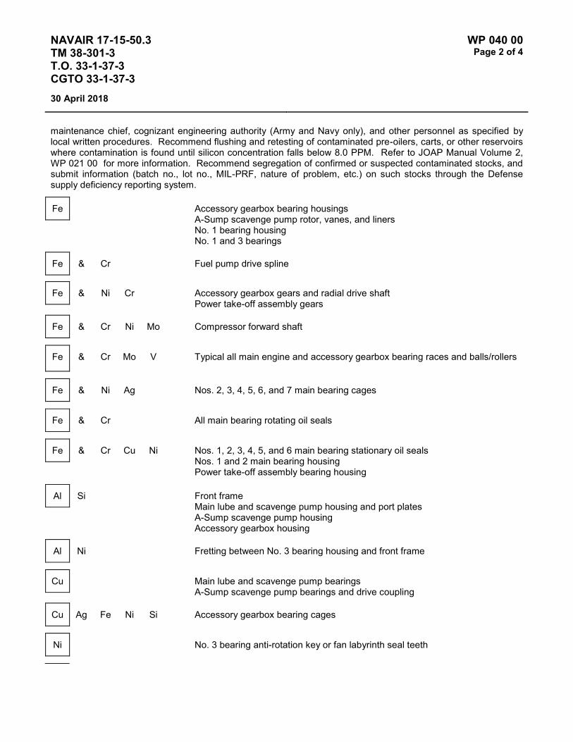
NAVAIR 17-15-50.3 TM 38-301-3 T.O. 33-1-37-3 CGTO 33-1-37-3
WP 040 00 Page 2 of 4
30 April 2018
maintenance chief, cognizant engineering authority (Army and Navy only), and other personnel as specified by local written procedures. Recommend flushing and retesting of contaminated pre-oilers, carts, or other reservoirs where contamination is found until silicon concentration falls below 8.0 PPM. Refer to JOAP Manual Volume 2, WP 021 00 for more information. Recommend segregation of confirmed or suspected contaminated stocks, and submit information (batch no., lot no., MIL-PRF, nature of problem, etc.) on such stocks through the Defense supply deficiency reporting system.
Fe Accessory gearbox bearing housings A-Sump scavenge pump rotor, vanes, and liners No. 1 bearing housing No. 1 and 3 bearings
Fe & Cr Fuel pump drive spline
Fe & Ni Cr Accessory gearbox gears and radial drive shaft Power take-off assembly gears
Fe & Cr Ni Mo Compressor forward shaft
Fe & Cr Mo V Typical all main engine and accessory gearbox bearing races and balls/rollers
Fe & Ni Ag Nos. 2, 3, 4, 5, 6, and 7 main bearing cages
Fe & Cr All main bearing rotating oil seals
Fe & Cr Cu Ni Nos. 1, 2, 3, 4, 5, and 6 main bearing stationary oil seals Nos. 1 and 2 main bearing housing Power take-off assembly bearing housing
Al Si Front frame Main lube and scavenge pump housing and port plates A-Sump scavenge pump housing Accessory gearbox housing
Al Ni Fretting between No. 3 bearing housing and front frame
Cu Main lube and scavenge pump bearings A-Sump scavenge pump bearings and drive coupling
Cu Ag Fe Ni Si Accessory gearbox bearing cages
Ni No. 3 bearing anti-rotation key or fan labyrinth seal teeth

NAVAIR 17-15-50.3 TM 38-301-3 T.O. 33-1-37-3 CGTO 33-1-37-3
WP 040 00 Page 3 of 4
30 April 2018
Ni & Fe Mo No. 7 main bearing rotating oil seal
Ni & Cr Fe Mo Nos. 3, 4, 5 and 7 main bearing housings
Ni & Cr Fe No. 6 main bearing housing
Ni & Cu Si Ag No. 1 main bearing cage
Ni & Al V Front fan shaft Power take-off assembly bearing housing No. 7 main bearing stationary oil seal
Ti & Fe Cr Mo V Fan forward shaft spline wear or No. 1 or No. 2 bearing loose on fan forward shaft
NOTES
1. A rapid increase of Fe could indicate No. 1 bearing spalling. This failure occurs quickly, often with OAP readings within normal range. If a 4 PPM increase of Fe, or if abnormal trend of any metal is noted, or if Fe increases in combination with a 2 PPM increase in two or more of Ag, Cr, or Ni between consecutive samples:
Perform chip detector inspection per T.O.'s 1A-10C-2-71JG-5 and 2JA18-2-2-1. If engine is not rejected for chip detector contamination, perform three ground runs: idle-80% (for 5 minutes) idle (for 5 minutes) per run and take OAP sample after each run.
a. If ground runs confirm the 4 PPM increase in Fe or abnormal trend, remove engine for teardown inspection.
b. If the 4 PPM increase in Fe or abnormal trend is not confirmed, place engine on special sampling after every flight until normal trend is firmly reestablished.
2. High Si indicates oil contamination, possibly from engine wash chemicals. Oil tank should be drained and reserviced.
3. Fuel contamination in oil indicates oil cooler leak.

NAVAIR 17-15-50.3 TM 38-301-3 T.O. 33-1-37-3 CGTO 33-1-37-3
WP 040 00 Page 4 of 4
30 April 2018
OIL CAPACITY AND C0NSUMPTION INFORMATION REFERENCE MATERIAL ONLY
1. T.O. Reference: 1A-10C-2-1-3, Chapter 3
2. Oil Capacity of the TF34-GE-100A engine is 7 quarts.
3. Allowable oil consumption rate (quantity per time) is one-half (½) pint per hour.
4. Recommended oil consumption inspection interval: Following the first flight of the day or as directed by T.O. 1A-10C-6.
5. Action to take if maximum oil consumption rate is exceeded: Troubleshoot in accordance with T.O. 1A-10C-2-71TS-1.

NAVAIR 17-15-50.3 TM 38-301-3 T.O. 33-1-37-3 CGTO 33-1-37-3
WP 041 00 Page 1 of 4
30 April 2018
TYPE EQUIPMENT Aircraft Engine
MANUFACTURER General Electric
EQUIPMENT/SYSTEM MODEL NUMBER/DESIGNATION
WEAPON SYSTEM PLATFORM(S)
JOAP TYPE EQUIPMENT CODE
TF34-GE-400B S-3B KDBA
LUBRICATING OIL MIL-PRF-23699 or MIL-PRF-7808 for cold weather ops.
TECHNICAL AUTHORITY NAVAIR
STATUS Aircraft and engine retired. WP retained for reference.
Table 1 - JOAP ATOMIC EMISSION ROTRODE LIMITS
Fe Ag Al Cr Cu Mg Ni Ti B Si Zn
Abnormal Trend (PPM Increase in 10 Hrs)
4 2 2 2 2 3 2 2
Normal Range 0-9 0-1 0 0-1 0-1 0-2 0-3 0-1 Marginal Range 10-14 2-5 1-3 2-5 2-4 3-10 4 3 High Range 15-17 6-7 4-5 6 5-10 11-13 5-6 4 Abnormal ≥18 ≥8 ≥6 ≥7 ≥11 ≥14 ≥7 ≥5 10 10 10
Elevated boron (B) and/or zinc (Zn) concentrations usually indicate contamination with another oil type, primarily MIL-PRF-2104. Recommend resampling and retesting immediately. If new value exceeds 8.0 PPM, run check with D19-0 to ensure proper instrument function. When proper function is confirmed, report both results and suspected contamination with MIL-PRF-2104 to chain of command, maintenance chief, cognizant engineering authority (Army and Navy only), and other personnel as specified by local written procedures. Recommend flushing and retesting of contaminated pre-oilers, carts, or other reservoirs where contamination is found until both B and Zn concentrations fall below 8.0 PPM. Refer to JOAP Manual Volume 2, WP 021 00 for more information. Recommend segregation of confirmed or suspected contaminated stocks, and submit information (batch no., lot no., MIL-PRF, nature of problem, etc.) on such stocks through the Defense supply deficiency reporting system.
Elevated silicon (Si) concentration usually indicates contamination with soil, sand, or dust. If aluminum (Al) is also elevated, this suggests the presence of clay or soil. Recommend resampling and retesting immediately. If new value exceeds 8.0 PPM, run check with D19-0 to ensure proper instrument function. When proper function is confirmed, report both results and suspected contamination with soil, sand, or dust to chain of command, maintenance chief, cognizant engineering authority (Army and Navy only), and other personnel as specified by local written procedures. Recommend flushing and retesting of contaminated pre-oilers, carts, or other reservoirs where contamination is found until silicon concentration falls below 8.0 PPM. Refer to JOAP Manual Volume 2, WP 021 00 for more information. Recommend segregation of confirmed or suspected contaminated stocks, and submit information (batch no., lot no., MIL-PRF, nature of problem, etc.) on such stocks through the Defense

NAVAIR 17-15-50.3 TM 38-301-3 T.O. 33-1-37-3 CGTO 33-1-37-3
WP 041 00 Page 2 of 4
30 April 2018
supply deficiency reporting system.
Fe Accessory gearbox bearing housings Main lube and scavenge pump generators and shaft A-Sump scavenge pump rotor, vanes, and liners
Fe & Cr Fuel pump drive spline
Fe & Ni Cr Accessory gearbox gears and radial drive shaft Power take-off assembly gears
Fe & Cr Compressor forward shaft
Ni Mo
Fe & Cr Typical all main engine and accessory gearbox bearing races and balls/rollers
Mo V
Fe & Ni Nos. 2, 3, 4, 5, 6, and 7 main bearing cages
Ag Plate
Fe & Cr Plate All main bearing rotating oil seals
Fe & Cr Cu Ni Nos. 1, 2, 3, 4, 5, and 6 main bearing stationary oil seals Nos. 1 and 2 main bearing housing Power take-off assembly bearing housing
Al Si Front frame Main lube and scavenge pump housing and port plates A-Sump scavenge pump housing Accessory gearbox housing
Cu Main lube and scavenge pump bearings A-Sump scavenge pump bearings and drive coupling
Cu & Si Zn Fe Accessory gearbox bearing cages
Ag Plate

NAVAIR 17-15-50.3 TM 38-301-3 T.O. 33-1-37-3 CGTO 33-1-37-3
WP 041 00 Page 3 of 4
30 April 2018
Ni & Fe Mo No. 7 main bearing rotating oil seal
Cr Plate
Ni & Cr Fe Mo Nos. 3, 4, 5 and 7 main bearing housings
Ni & Cr Fe No. 6 main bearing housing
Ni & Cu Si No. 1 main bearing cage
Ag Plate
Ni & Al V Front fan shaft Power take-off assembly bearing housing No. 7 main bearing stationary oil seal
Ag Silver, by itself, probably PTO spline wear

NAVAIR 17-15-50.3 TM 38-301-3 T.O. 33-1-37-3 CGTO 33-1-37-3
WP 041 00 Page 4 of 4
30 April 2018
NOTES
High Silver by itself is not cause for rejection of engine.
A rapid increase of Fe could indicate No. 1 bearing spalling. This failure occurs quickly, often with (oil analysis program) readings within normal range.
1. If a 4 PPM increase of Fe, or if abnormal trend of any metal is noted, or if Fe increases in combination with a 2 PPM increase in two or more of Ag, Cr, or Ni between consecutive samples.
Perform chip detector inspection per NAVAIR 01-S3AAA-2-4.6, WP 008 04. If engine is not rejected for chip detector contamination, perform three ground runs: Idle-80% (for 5 minutes) idle (for 5 minutes) per run and take oil analysis program sample after each run.
a. If ground runs confirm the 4 PPM increase in Fe or abnormal trend, remove engine for teardown inspection.
b. If the 4 PPM increase in Fe or abnormal trend is not confirmed, place engine on special sampling after every flight until normal trend is firmly reestablished.
2. High Si indicates oil contamination, possible from engine wash chemicals. Oil tank should be drained and reserviced.
3. Fuel contamination in oil indicates oil cooler leak.
4. High Al indicates possible contamination from hydraulic pump expansion plug.
5. The point of contact for this equipment is Graham Harlowe (Code 05311), DSN 963-7828 or FTS (510) 263-7828.

NAVAIR 17-15-50.3 TM 38-301-3 T.O. 33-1-37-3 CGTO 33-1-37-3
WP 042 00 Page 1 of 4
30 April 2018
TYPE EQUIPMENT Aircraft Engine
MANUFACTURER General Electric
EQUIPMENT/SYSTEM MODEL NUMBER/DESIGNATION
WEAPON SYSTEM PLATFORM(S)
JOAP TYPE EQUIPMENT CODE
TF39-GE-1 C-5 KGAA
LUBRICATING OIL MIL-PRF-7808
TECHNICAL AUTHORITY Air Force
STATUS In Use
Table 1 - JOAP ATOMIC EMISSION ROTRODE LIMITS
Fe Ag Al Cr Cu Mg Ti B Si Zn
* Abnormal Trend (PPM Increase in 10 Hrs)
25 3 8 4 4 10 8
Normal Range 0-12 0-1 0-1 0-1 0-6 0-40 0-3 Marginal Range 13-38 2-4 2-4 2 7-13 41-65 4-7
High Range 39-74 5-9 5-14 3-9 14-19 66-103 8-15
Abnormal ≥75 ≥10 ≥15 ≥10 ≥20 ≥104 ≥16 10 10 10 NOTE: * If the calculated PPM trend value is equal to or greater than the trend PPM value limit, the engine has an
abnormal trend.
Elevated boron (B) and/or zinc (Zn) concentrations usually indicate contamination with another oil type, primarily MIL-PRF-2104. Recommend resampling and retesting immediately. If new value exceeds 8.0 PPM, run check with D19-0 to ensure proper instrument function. When proper function is confirmed, report both results and suspected contamination with MIL-PRF-2104 to chain of command, maintenance chief, cognizant engineering authority (Army and Navy only), and other personnel as specified by local written procedures. Recommend flushing and retesting of contaminated pre-oilers, carts, or other reservoirs where contamination is found until both B and Zn concentrations fall below 8.0 PPM. Refer to JOAP Manual Volume 2, WP 021 00 for more information. Recommend segregation of confirmed or suspected contaminated stocks, and submit information (batch no., lot no., MIL-PRF, nature of problem, etc.) on such stocks through the Defense supply deficiency reporting system.
Elevated silicon (Si) concentration usually indicates contamination with soil, sand, or dust. If aluminum (Al) is also elevated, this suggests the presence of clay or soil. Recommend resampling and retesting immediately. If new value exceeds 8.0 PPM, run check with D19-0 to ensure proper instrument function. When proper function is confirmed, report both results and suspected contamination with soil, sand, or dust to chain of command, maintenance chief, cognizant engineering authority (Army and Navy only), and other personnel as specified by

NAVAIR 17-15-50.3 TM 38-301-3 T.O. 33-1-37-3 CGTO 33-1-37-3
WP 042 00 Page 2 of 4
30 April 2018
local written procedures. Recommend flushing and retesting of contaminated pre-oilers, carts, or other reservoirs where contamination is found until silicon concentration falls below 8.0 PPM. Refer to JOAP Manual Volume 2, WP 021 00 for more information. Recommend segregation of confirmed or suspected contaminated stocks, and submit information (batch no., lot no., MIL-PRF, nature of problem, etc.) on such stocks through the Defense supply deficiency reporting system.
Fe Inlet and transfer gearbox bearing housings and retainers
Fe & Ag Inlet and transfer gearbox shafts
Fe & Cr Inlet and transfer gearbox bearings and races No. 1 and 3 main bearing rollers and races
Fe & Ni No. 4B bearing housing spanner nut
Fe & Mn Lube and scavenge pump shaft and elements
Fe & Ag Ni No. 1 main bearing cages
Fe & Cr Ni Inlet and transfer gearbox gears
Fe & Cr Cu Ni Nos. 4, 6 and 7 main bearing rotating oil seals
Fe & Ag Cr Nos. 4, 5, 6 and 7 main bearing stationary air and oil seal
Cu Ni
Fe & Cr Mo V Nos. 2, 4, 5, 6 and 7 main bearing rollers and races No. 5 main bearing fan shaft
Fe & Ni Co Mo No. 2 main bearing fan shaft
Al & Mg Lube and scavenge pump air/oil separator seal
Al & Si Forward scavenge pump housing

NAVAIR 17-15-50.3 TM 38-301-3 T.O. 33-1-37-3 CGTO 33-1-37-3
WP 042 00 Page 3 of 4
30 April 2018
Al & Cu Si Lube and scavenge pump cover
Cu & Fe Ag Si No. 3 main bearing cages
Cu & Fe Ag Nos. 2, 4, 5, 6 and 7 main bearing cages
Si Zn Inlet and transfer gearbox cages
Cu & Al Zn Mn Lube and scavenge pump bearings
Mg & Zn Transfer gearbox housing
Ti & Al Sn No. 2 main bearing fan frame
Ti & Al V No. 1 main bearing fan stub shaft and rotating air and oil seal No. 3 main bearing stage two-rotor disc (rotating oil seal) No. 5 main bearing HP turbine rear shaft (rotating oil seal)
NOTE
Comparison of teardown findings with wear metal histories has shown that Fe wear metal increase rates of 1 PPM per operating hour appear to be normal and may be associated with gradual wear of the inlet gearbox splined adapter. Wear metal increase rates of 2 to 2½ PPM per operating hour appear to be abnormal and may be associated with more severe gearbox or engine bearing problems. High Ti and Fe may be caused by cracked and spinning No. 3 bearing inner race.
OIL CAPACITY AND CONSUMPTION INFORMATION
1. Oil capacity of engine: 9.1 gallons (at full mark on dipstick).
2. Allowable oil consumption rate: Reference T.O. 1C-5A-2-4, Table 3.1:
Home station: 2 pints per hour maximum
Enroute: 4 pints per hour maximum
3. Oil consumption inspection interval: Ref. T.O. 1C-5A-2-4, Table 3.1, as needed.

NAVAIR 17-15-50.3 TM 38-301-3 T.O. 33-1-37-3 CGTO 33-1-37-3
WP 042 00 Page 4 of 4
30 April 2018
4. Actions to take if maximum allowable oil consumption is exceeded:
Ref T.O. 1C-5A-2-4, Table 3.1
Correct fault or replace engine

NAVAIR 17-15-50.3 TM 38-301-3 T.O. 33-1-37-3 CGTO 33-1-37-3
WP 043 00 Page 1 of 4
30 April 2018
TYPE EQUIPMENT Aircraft Engine
MANUFACTURER Allison / Rolls Royce
EQUIPMENT/SYSTEM MODEL NUMBER/DESIGNATION
WEAPON SYSTEM PLATFORM(S)
JOAP TYPE EQUIPMENT CODE
TF41-A-2/-2A/-2B/-2C/-400/-402C/402D A-7 N/A
LUBRICATING OIL MIL-PRF-23699
TECHNICAL AUTHORITY NAVAIR
STATUS Aircraft and engine retired. WP retained for reference.
Table 1 - JOAP ATOMIC EMISSION ROTRODE LIMITS
* Fe * Ag * Al * Cu B ** Si Zn
Abnormal Trend 4 3 3 3 Normal Range 0-10 0-6 0-6 0-6 Marginal Range 11-12 7 7 7 High Range 13-15 8-9 8-9 8-9 Abnormal ≥16 ≥10 ≥10 ≥10 10 10 NOTES: * Refer to important Notes section on following page. Use lab advice code F in any case where TF41
engine oil samples have critical wearmetals at the upper limit of normal range or above and/or if the trend is abnormal. Other appropriate codes may be used after the code F recommendation.
** Refer to Note 3 for Si guidance.
Elevated boron (B) and/or zinc (Zn) concentrations usually indicate contamination with another oil type, primarily MIL-PRF-2104. Recommend resampling and retesting immediately. If new value exceeds 8.0 PPM, run check with D19-0 to ensure proper instrument function. When proper function is confirmed, report both results and suspected contamination with MIL-PRF-2104 to chain of command, maintenance chief, cognizant engineering authority (Army and Navy only), and other personnel as specified by local written procedures. Recommend flushing and retesting of contaminated pre-oilers, carts, or other reservoirs where contamination is found until both B and Zn concentrations fall below 8.0 PPM. Refer to JOAP Manual Volume 2, WP 021 00 for more information. Recommend segregation of confirmed or suspected contaminated stocks, and submit information (batch no., lot no., MIL-PRF, nature of problem, etc.) on such stocks through the Defense supply deficiency reporting system.
NOTES
1. Caution must be exercised when evaluating this engine due to high oil consumption and small oil tank capacity. Use of decision tables alone as a basis for evaluation may be misleading. Trend analysis must be utilized to successfully evaluate this engine. It is also recommended that test results be plotted on graphs to assist in evaluations. A developing trend may be

NAVAIR 17-15-50.3 TM 38-301-3 T.O. 33-1-37-3 CGTO 33-1-37-3
WP 043 00 Page 2 of 4
30 April 2018
indicated with increases of one or two PPM in one or more elements. If a developing trend is suspected by small increases of wear metal (s), one or two PPM, maintain close surveillance. DO NOT REQUEST DRAIN AND FLUSH. Use the next sample to confirm past results. If the suspected developing trend is 3 PPM or greater in one or more elements, immediately notify maintenance NOT TO ADD OR CHANGE OIL and request a check sample after 30 minutes ground run. If a trend continues to develop, in either situation, notify the propulsion branch chief and recommend positive maintenance action be taken.
2. Use lab advice code F in any case where TF41 engine oil samples have critical wear metals exceeding the normal range.
3. High silicon indicates contamination probably due to sampling error. However, consistently high silicon of 30 PPM or more indicates contamination. Flush oil system in accordance with NAVAIR 02B-5EA-6-1 or NAVAIR 01-45AAE/F-2-4.6 and sample after five hours of operation to ensure silicon removal.
4. Increases in Cu by itself may indicate defective bearing. Increases in Cu accompanied by increases in Fe may also indicate abnormal bearing wear and /or seal ring wear. Increases in Cr by itself in any amount may indicate rotation of no. 6 bearing outer race in housing. Increases in Cr accompanied by Fe may indicate piston ring seal wear and could result in excessive oil consumption. Increase in Al may indicate fretting internal gearbox cover and /or oil pump. Increases in Mg may indicate abnormal wear in high speed gearbox.
SOURCES OF WEAR:
Fe Main bearing races, rollers, balls, and sleeves. gearbox , No. 2 Bearing and oil pump gears, gearbox bearings and bearing carries, No.6 bearing oil seal liner, external gearbox , oil pump and nos. 3, 4 and 5 bearing shafts, (chromium plating under no. 4 bearing inner race is a repair procedure) and nos. 6 and 7 bearing housing. (chromium plating at split line and under outer race is a repair procedure.)
Fe & Cr Main bearing oil seal rings
Al Internal gearbox, oil pump and no. 2 bearing housing external gearbox air blown seals and accessories drive pads and scavenge oil pump housing
Cu Main bearing and gearbox cages and oil pump bushings
NOTES
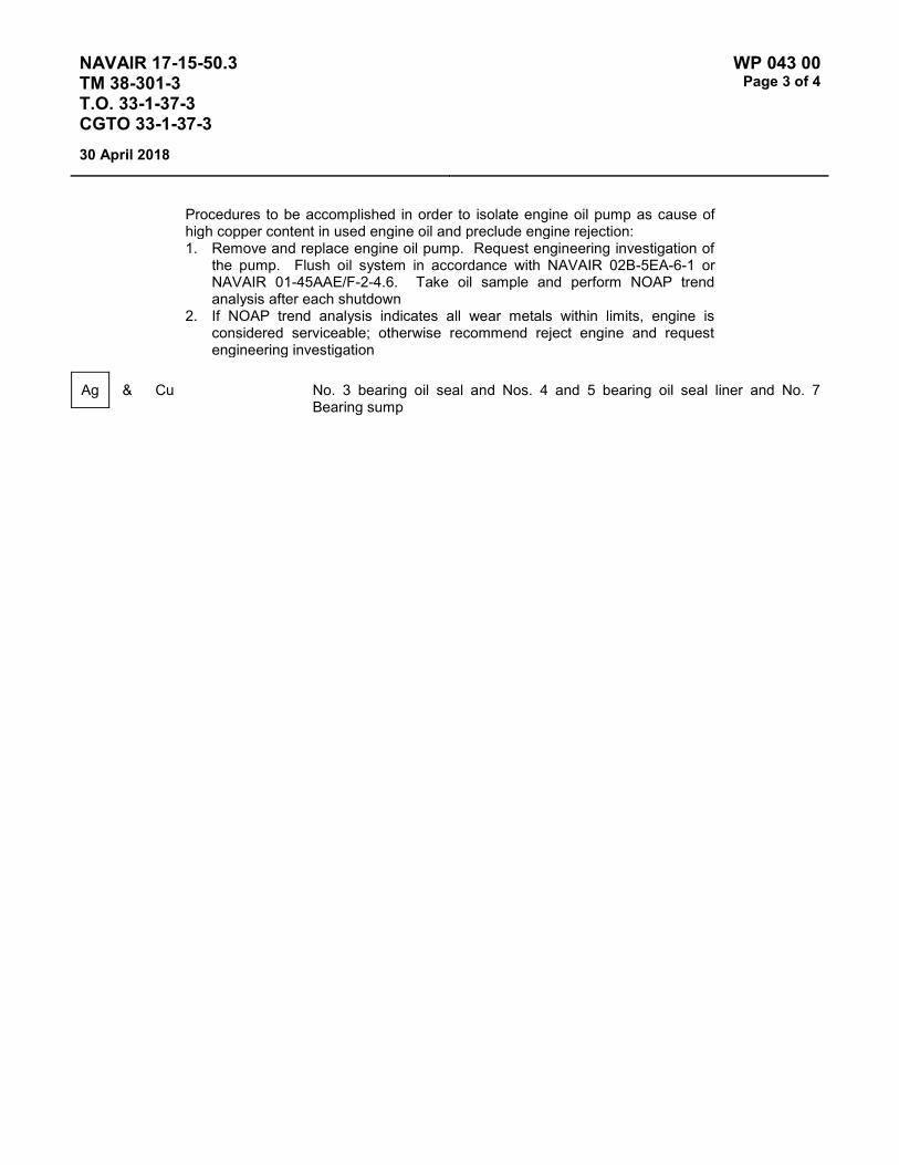
NAVAIR 17-15-50.3 TM 38-301-3 T.O. 33-1-37-3 CGTO 33-1-37-3
WP 043 00 Page 3 of 4
30 April 2018
Procedures to be accomplished in order to isolate engine oil pump as cause of high copper content in used engine oil and preclude engine rejection: 1. Remove and replace engine oil pump. Request engineering investigation of
the pump. Flush oil system in accordance with NAVAIR 02B-5EA-6-1 or NAVAIR 01-45AAE/F-2-4.6. Take oil sample and perform NOAP trend analysis after each shutdown
2. If NOAP trend analysis indicates all wear metals within limits, engine is considered serviceable; otherwise recommend reject engine and request engineering investigation
Ag & Cu No. 3 bearing oil seal and Nos. 4 and 5 bearing oil seal liner and No. 7 Bearing sump

NAVAIR 17-15-50.3 TM 38-301-3 T.O. 33-1-37-3 CGTO 33-1-37-3
WP 043 00 Page 4 of 4
30 April 2018
This Page Intentionally Left Blank

NAVAIR 17-15-50.3 TM 38-301-3 T.O. 33-1-37-3 CGTO 33-1-37-3
WP 044 00 Page 1 of 2
30 April 2018
TYPE EQUIPMENT Aircraft Engine
MANUFACTURER Pratt & Whitney
EQUIPMENT/SYSTEM MODEL NUMBER/DESIGNATION
WEAPON SYSTEM PLATFORM(S)
JOAP TYPE EQUIPMENT CODE
JT8D-9 C-9 KKBA
JT8D-7 C-22 KKAA
LUBRICATING OIL MIL-PRF-7808
TECHNICAL AUTHORITY Air Force
STATUS Aircraft and engine retired. WP retained for reference.
Table 1 - JOAP ATOMIC EMISSION ROTRODE LIMITS
Fe Ag Al Cr Cu Mg Ni Ti B Si Zn
Abnormal Trend (PPM Increase in 10 Hrs)
5 2 2 2 3 3 2 3 5
Normal Range 0-15 0-3 0-5 0-3 0-5 0-5 0-3 0-5 0-16 * Marginal Range 16-19 4-6 6-7 4-6 6-7 6-7 4-5 6-7 17-24 ** High Range 20-24 7-8 8-9 7-9 8-9 8-9 6-8 8-9 25-49 *** Abnormal ≥25 ≥9 ≥10 ≥10 ≥10 ≥10 ≥9 ≥10 10 ≥50 10 NOTES: * Reduce sampling interval by one-half. ** Resample each return to home station. *** Check main oil screen/filter for metal contamination; resample at every return to home station for 100 hours.
Elevated boron (B) and/or zinc (Zn) concentrations usually indicate contamination with another oil type, primarily MIL-PRF-2104. Recommend resampling and retesting immediately. If new value exceeds 8.0 PPM, run check with D19-0 to ensure proper instrument function. When proper function is confirmed, report both results and suspected contamination with MIL-PRF-2104 to chain of command, maintenance chief, cognizant engineering authority (Army and Navy only), and other personnel as specified by local written procedures. Recommend flushing and retesting of contaminated pre-oilers, carts, or other reservoirs where contamination is found until both B and Zn concentrations fall below 8.0 PPM. Refer to JOAP Manual Volume 2, WP 021 00 for more information. Recommend segregation of confirmed or suspected contaminated stocks, and submit information (batch no., lot no., MIL-PRF, nature of problem, etc.) on such stocks through the Defense supply deficiency reporting system.
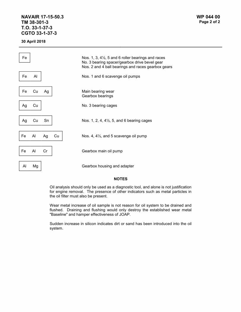
NAVAIR 17-15-50.3 TM 38-301-3 T.O. 33-1-37-3 CGTO 33-1-37-3
WP 044 00 Page 2 of 2
30 April 2018
Fe Nos. 1, 3, 4½, 5 and 6 roller bearings and races No. 3 bearing spacer/gearbox drive bevel gear Nos. 2 and 4 ball bearings and races gearbox gears
Fe Al Nos. 1 and 6 scavenge oil pumps
Fe Cu Ag Main bearing wear Gearbox bearings
Ag Cu No. 3 bearing cages
Ag Cu Sn Nos. 1, 2, 4, 4½, 5, and 6 bearing cages
Fe Al Ag Cu Nos. 4, 4½, and 5 scavenge oil pump
Fe Al Cr Gearbox main oil pump
Al Mg Gearbox housing and adapter
NOTES
Oil analysis should only be used as a diagnostic tool, and alone is not justification for engine removal. The presence of other indicators such as metal particles in the oil filter must also be present.
Wear metal increase of oil sample is not reason for oil system to be drained and flushed. Draining and flushing would only destroy the established wear metal "Baseline" and hamper effectiveness of JOAP.
Sudden increase in silicon indicates dirt or sand has been introduced into the oil system.

NAVAIR 17-15-50.3 TM 38-301-3 T.O. 33-1-37-3 CGTO 33-1-37-3
WP 045 00 Page 1 of 4
30 April 2018
TYPE EQUIPMENT Aircraft Engine
MANUFACTURER Pratt & Whitney
EQUIPMENT/SYSTEM MODEL NUMBER/DESIGNATION
WEAPON SYSTEM PLATFORM(S)
JOAP TYPE EQUIPMENT CODE
JT8D-9A C-9 KKBB
LUBRICATING OIL MIL-PRF-23699
TECHNICAL AUTHORITY NAVAIR
STATUS Aircraft retired. WP retained for reference.
Table 1 - JOAP ATOMIC EMISSION ROTRODE LIMITS
Fe Ag Al Cr Cu Mg Ni Ti B Si Zn
* Abnormal Trend (PPM Increase in 10 Hrs)
5 2 2 2 3 3 2 3 5
Normal Range 0-15 0-3 0-5 0-3 0-5 0-5 0-3 0-5 0-16 Marginal Range 16-19 4-6 6-7 4-6 6-7 6-7 4-5 6-7 17-24 High Range 20-24 7-8 8-9 7-9 8-9 8-9 6-8 8-9 25-49 Abnormal ≥25 ≥9 ≥10 ≥10 ≥10 ≥10 ≥9 ≥10 10 ≥50 10 NOTE: * If the calculated PPM trend value is equal to or greater than the trend PPM value limit, the engine has an
abnormal trend.
Elevated boron (B) and/or zinc (Zn) concentrations usually indicate contamination with another oil type, primarily MIL-PRF-2104. Recommend resampling and retesting immediately. If new value exceeds 8.0 PPM, run check with D19-0 to ensure proper instrument function. When proper function is confirmed, report both results and suspected contamination with MIL-PRF-2104 to chain of command, maintenance chief, cognizant engineering authority (Army and Navy only), and other personnel as specified by local written procedures. Recommend flushing and retesting of contaminated pre-oilers, carts, or other reservoirs where contamination is found until both B and Zn concentrations fall below 8.0 PPM. Refer to JOAP Manual Volume 2, WP 021 00 for more information. Recommend segregation of confirmed or suspected contaminated stocks, and submit information (batch no., lot no., MIL-PRF, nature of problem, etc.) on such stocks through the Defense supply deficiency reporting system.
NOTE
1. Marginal Range:
a. Reduce sampling interval to every 100 hours for 200 hours.
b. If PPM remains in marginal range or decreases to normal range, return

NAVAIR 17-15-50.3 TM 38-301-3 T.O. 33-1-37-3 CGTO 33-1-37-3
WP 045 00 Page 2 of 4
30 April 2018
to routine sampling intervals.
2. High Range:
a. Within 10 hours, visually inspect the oil filter and electrically inspect chip detectors in accordance with NAVAIR 01-C9B-2-79.
b. Resample oil and perform spectrometric oil analysis every 100 hours for 400 hours.
c. If PPM remains in the high range or decreases into marginal range, and no metal is evident in the oil system, return to routine oil sampling intervals.
3. Abnormal Range or Abnormal Trends:
a. Within 10 flight hours, remove and visually inspect main oil filter and chip detectors in accordance with NAVAIR 01-C9B-2-79.
b. Within 50 hours, resample oil for Spectrometric Analysis.
c. If PPM remains in the abnormal range after the 50 hour sample, the oil lab should contact the CFA for disposition prior to issuing further recommendations. The operator should contact the CFA for further direction through the appropriate chain of command.
CFA:
DSN: 342-3575/
COMM: (301) 342-3575
FAX: 342-3965
COMM: (301) 342-3965
MESSAGE: PROGMGR AIR TWO TWO SEVEN PATUXENT RIVER MD//2271B1//
MAILSTOP 34 CODE 2271B1
46989 MCLEOD ROAD
NAS PATUXENT RIVER MD 20670-5449
Fe Nos. 1, 3, 4½, 5 and 6 roller bearings and races, No. 3 bearing spacer/gearbox drive bevel gear Nos. 2 and 4 ball bearings and races gearbox gears
Fe Al Nos. 1 and 6 scavenge oil pumps

NAVAIR 17-15-50.3 TM 38-301-3 T.O. 33-1-37-3 CGTO 33-1-37-3
WP 045 00 Page 3 of 4
30 April 2018
Fe Cu Ag Main bearing wear
Ag Cu No. 3 bearing cages
Ag Cu Sn Nos. 1, 2, 4, 4½, 5 and 6 bearing cages
Fe Al Ag Cu Nos. 4, 4½, and 5 scavenge oil pump
Fe Al Cr Gearbox main oil pump
Al Mg Gearbox housing and adapter
NOTES
1. Abnormal concentration of wear metal discovered during Spectrometric Analysis should not by itself be justification for engine or oil-wetted component removal: a positive correlation should be made with other indicators, such as solid metal on chip detectors and/or solid metal in filter, vibration, burned oil, etc.
2. Engines with an indication of high or abnormal parts per million wear metal concentration should initially be inspected for solid particulate in the form of metal slivers, flakes, etc. If the initial inspection does not indicate solid particulate, then oil sampling should be accomplished at a reduced interval for a limited period of time, but without flight restriction. During the period of reduced sampling interval, operators should have an increased awareness of other oil system indicators.
3. Abnormal Fe and Cr concentrations at the microscopic level are not uncommon, and have been attributed to the following:
a. Rust accumulation on oil-wetted components: Rust within the engine oil system is not common, but may occur if the engine has been out of service for an extended period of time.
b. Bearing outer race slippages: Abnormal concentration of Fe may result if a bearing outer race slips within the bearing's liner. Bearing outer race to liner slippage is common within the gearbox. This condition may be temporary, or may continue without an adverse affect on component operation.
4. If increased wear metal concentrations are the result of a temporary condition, the levels will plateau, and eventually decrease through normal

NAVAIR 17-15-50.3 TM 38-301-3 T.O. 33-1-37-3 CGTO 33-1-37-3
WP 045 00 Page 4 of 4
30 April 2018
usage.
5. The oil system should not normally be drained and flushed, except if contaminated by hydraulic fluid, fuel, etc.
6. If darkening of the oil occurs, the most immediate concern is overheating of the oil. Oil overheating will generally be evidenced by darkening of the oil, accompanied by a burned oil smell (see P&W Maintenance Manual P/N 481671, Troubleshooting "Black Oil"). Synthetic ester-based aviation oils may undergo a color change in service. Synthetic turbo oils contain oxidation inhibitors in their formulations, and most, if not all, of the better oxidation inhibitors are photosensitive. A new oil, light straw in color, may go through all colors of the spectrum and end up jet black as it performs its service. The color is imparted by the oxidation inhibitor, which darkens as it performs its function.

NAVAIR 17-15-50.3 TM 38-301-3 T.O. 33-1-37-3 CGTO 33-1-37-3
WP 046 00 Page 1 of 6
30 April 2018
TYPE EQUIPMENT Aircraft Engine
MANUFACTURER Pratt & Whitney
EQUIPMENT/SYSTEM MODEL NUMBER/DESIGNATION
WEAPON SYSTEM PLATFORM(S)
JOAP TYPE EQUIPMENT CODE
F100-PW-100 F-15 FAAA
F100-PW-220 F-15 FACA
F100-PW-229 F-15 FADA
F100-PW-100 F-16 FAEA
F100-PW-200 F-16 FABA
F100-PW-220 F-16 FACB
F100-PW-229 F-16 FADB
LUBRICATING OIL MIL-PRF-7808
TECHNICAL AUTHORITY Air Force
STATUS In Use
Table 1 - JOAP ATOMIC EMISSION ROTRODE LIMITS
Fe Ag Al Cr Cu Mg Ni Ti B * Si Zn
Abnormal Trend (PPM Increase in 10 Hrs)
4 2 4 2 2 4
Normal Range 0-10 0-2 0-10 0-4 0-4 0-10 Marginal Range 11-12 N/A 11-12 5 5 11-12 High Range 13-14 3 13-14 6 6 13-14 Abnormal ≥15 ≥4 ≥15 ≥7 ≥7 ≥15 10 10 NOTE: * Refer to #4 in F-100 Decision Making Guidelines section for specific Si wear metal guidance.
Elevated boron (B) and/or zinc (Zn) concentrations usually indicate contamination with another oil type, primarily MIL-PRF-2104. Recommend resampling and retesting immediately. If new value exceeds 8.0 PPM, run check with D19-0 to ensure proper instrument function. When proper function is confirmed, report both results and suspected contamination with MIL-PRF-2104 to chain of command, maintenance chief, cognizant engineering authority (Army and Navy only), and other personnel as specified by local written procedures. Recommend flushing and retesting of contaminated pre-oilers, carts, or other reservoirs where contamination is found until both

NAVAIR 17-15-50.3 TM 38-301-3 T.O. 33-1-37-3 CGTO 33-1-37-3
WP 046 00 Page 2 of 6
30 April 2018
B and Zn concentrations fall below 8.0 PPM. Refer to JOAP Manual Volume 2, WP 021 00 for more information. Recommend segregation of confirmed or suspected contaminated stocks, and submit information (batch no., lot no., MIL-PRF, nature of problem, etc.) on such stocks through the Defense supply deficiency reporting system.
Fe and Ti are significant wear metals in this engine.
Fe Nos. 1, 2, 3, 4, and 5 bearing balls/rollers and races No. 1 area inner bearing sleeve No. 5 seal plate hub Accessory drive bearing balls/rollers, races and gears Gearbox baffle (loose retaining nut)
Ag Nos. 1, 2, 3, 4 and 5 accessory drive bearing cages
Fe & Ni No. 4 bearing spinning on high compressor hub
Ni No. 4 bearing spinning on high compressor hub
Ni Fe & Cr No. 4 bearing spinning on high compressor hub
Fe & Cr No. 4 bearing spinning on high compressor hub
Cr No. 4 bearing spinning on high compressor hub
Al Oil filter assembly, oil pump and accessory drive gearbox
Ti & Fe No. 5 bearing compartment
F-100 DECISION MAKING GUIDELINES
1. Engine teardown or surveillance is required for any of the following:
a. Any wear metal exceeds the abnormal limit. Teardown is required.
b. Fe or Ti increase by the value of their abnormal trend within a 10 hour engine operating period (total operating time). Surveillance is required for 10 hour total operating time.
c. While on surveillance for Fe, Fe increases above the value that caused surveillance by any amount. Teardown is required.

NAVAIR 17-15-50.3 TM 38-301-3 T.O. 33-1-37-3 CGTO 33-1-37-3
WP 046 00 Page 3 of 6
30 April 2018
d. While on surveillance for Ti, Ti increases above any other sample taken during surveillance by the abnormal trend value. Teardown is required.
e. Fe increases by the single sample jump limit, 5 PPM or more, between any two consecutive samples. Teardown is required.
f. Fe increases by the No. 4 bearing teardown limit, 9 PPM or more, within a 10 hour period. Teardown of the No. 4 bearing is required, unless positive identification of another wear source can be made.
g. All engines which have been disassembled for inspection due to Fe limits being exceeded. Surveillance is required for 10 hours total operating time.
2. Any sample value which requires the engine to be placed under surveillance or requires teardown shall be confirmed by a reburn. Proper engine personnel shall be notified immediately. When an engine is put on surveillance, request for oil filter and chip detector inspection should be made.
3. When a F100 engine is on surveillance, oil samples must be drawn after each flight and analysis results must be known before the next flight. All chip detectors must be checked each time a sample is drawn. During ground or test cell operation of an engine on surveillance, oil samples must be drawn at intervals no longer than one hour total operating time. After an oil sample is drawn, the engine may not be run for more than one hour before oil analysis results are available.
4. When silicon (Si) reaches or exceeds 15 PPM, drain and flush the oil. Also change the oil pressure transmitter if PN4039126; not required for PN4059195.
5. The main engine bearing may fail without indication reflected in the JOAP analysis. Spalling of these bearings is detected by chip detectors.
6. If the oil sample has an apparent burnt odor, notify proper engine personnel of condition.
NOTE
A burnt oil condition is typically, but not always, accompanied by a darkened oil color and obvious burnt odor. The condition is generated by a local heat source. A burnt oil condition cannot be detected by an atomic emission rotrode oil analysis spectometer.
OIL CAPACITY AND CONSUMPTION INFORMATION
1. The F100 oil capacity is 5 gallons.
2. Allowable oil consumption rate is 0.125 gallons/hour.
3. Oil level is checked after every flight and consumption rate calculated at that time.
4. Maintenance action is required if consumption rate is exceeded, per troubleshooting technical order.
NOTES
1. Actions required if abnormal range or trend samples is confirmed: contact

NAVAIR 17-15-50.3 TM 38-301-3 T.O. 33-1-37-3 CGTO 33-1-37-3
WP 046 00 Page 4 of 6
30 April 2018
and advise propulsion flight of recommendation JOAP Code "T". Propulsion management will evaluate and determine appropriate engine maintenance actions based on OAP and applicable on condition maintenance technical manual for burnt oil.
2. Oil samples subjected to thermal degradation usually exhibit a burnt odor.
3. Burnt oil can occur after only one flight.
EXAMPLE: PRIOR TO SURVEILLANCE (FOR FE INCREASE IN 10 ENGINE HOURS)
JOAP RECORD ACTION REQUIRED REASON
HRS SINCE OIL CHANGE FE (PPM)
84 4 86 5 91 6 92 6 93 5
10 HRS
95 6 4 PPM*
97 7 101 9 RETURN OF THIS
SAMPLE REQUIRED THIS SAMPLE REPRESENTS A 4 PPM INCREASE (OR GREATER) WITHIN THE LAST 10 ENGINE OPERATING HOURS
101 (REBURN) 9 PLACE ENGINE ON
SURVEILLANCE REBURN VERIFIES ACCURACY OF 9 PPM READING
10 HRS
* 4 PPM or greater using JOAP Atomic Emission.

NAVAIR 17-15-50.3 TM 38-301-3 T.O. 33-1-37-3 CGTO 33-1-37-3
WP 046 00 Page 5 of 6
30 April 2018
EXAMPLE: PRIOR TO SURVEILLANCE (FOR FE INCREASE IN 10 ENGINE HOURS)
JOAP RECORD ACTION REQUIRED REASON
HRS SINCE OIL CHANGE FE (PPM)
91 6 92 6
93 5 10
HRS
95 6 REBURN 97 7 101 9 101 9 4 PPM* SURVEILLANCE
102 8 103 10 ENGINE TEARDOWN
REQUIRED ENGINE TEARDOWN IS REQUIRED DUE TO INCREASE ABOVE 9 PPM WHICH CAUSED ORIGINAL SURVEILLANCE
* 4 PPM or greater using JOAP Atomic Emission.

NAVAIR 17-15-50.3 TM 38-301-3 T.O. 33-1-37-3 CGTO 33-1-37-3
WP 046 00 Page 6 of 6
30 April 2018
This Page Intentionally Left Blank

NAVAIR 17-15-50.3 TM 38-301-3 T.O. 33-1-37-3 CGTO 33-1-37-3
WP 047 00 Page 1 of 4
30 April 2018
TYPE EQUIPMENT Aircraft Engine
MANUFACTURER General Electric
EQUIPMENT/SYSTEM MODEL NUMBER/DESIGNATION
WEAPON SYSTEM PLATFORM(S)
JOAP TYPE EQUIPMENT CODE
F101-GE-102 B-1B FBAA
LUBRICATING OIL MIL-PRF-7808
TECHNICAL AUTHORITY Air Force
STATUS In Use
Table 1 - JOAP ATOMIC EMISSION ROTRODE LIMITS
Fe Ag Al Cr Cu Mg Ni Ti Mo B Si Zn
Abnormal Trend (PPM Increase in 10 Hrs)
3 2 2 2 4 2 2 2 2 5 2
Normal Range 0-8 0-3 0-3 0-6 0-12 0-6 0-5 0-5 0-2 0-12 0-2 Marginal Range 9-11 4-5 4-5 7-8 13-16 7-8 6-7 6-7 3 13-15 3 High Range 12-13 6 6 9 17-19 9 8 8 4 16-19 4 Abnormal ≥14 ≥7 ≥7 ≥10 ≥20 ≥10 ≥9 ≥9 ≥5 10 ≥20 ≥5
Refer to note 12 below for information concerning Pb.
Elevated boron (B) and/or zinc (Zn) concentrations usually indicate contamination with another oil type, primarily MIL-PRF-2104. Recommend resampling and retesting immediately. If new value exceeds 8.0 PPM, run check with D19-0 to ensure proper instrument function. When proper function is confirmed, report both results and suspected contamination with MIL-PRF-2104 to chain of command, maintenance chief, cognizant engineering authority (Army and Navy only), and other personnel as specified by local written procedures. Recommend flushing and retesting of contaminated pre-oilers, carts, or other reservoirs where contamination is found until both B and Zn concentrations fall below 8.0 PPM. Refer to JOAP Manual Volume 2, WP 021 00 for more information. Recommend segregation of confirmed or suspected contaminated stocks, and submit information (batch no., lot no., MIL-PRF, nature of problem, etc.) on such stocks through the Defense supply deficiency reporting system.
Fe & Cr Typical all main engine, accessory gearbox and inlet gearbox bearing races and balls/rollers
Fe & Ni Ag All main engine, accessory gearbox and inlet gearbox bearing cages

NAVAIR 17-15-50.3 TM 38-301-3 T.O. 33-1-37-3 CGTO 33-1-37-3
WP 047 00 Page 2 of 4
30 April 2018
Fe & Ni Cr Gear/gearshafts in accessory gearbox and inlet gearbox; aft lube/scavenge pump coupling shaft
Mg Accessory gearbox housing
Cr May be used on some bearing journals during rework - required on LP shaft journals for Nos. 4 and 5 bearing and on HP shaft bore for No. 4 outer ring
Fe & Cr Ni Cu Frame lab seals, rotating lab seals and inlet gearbox housing
Fe & Cr Carbon seal housings
Fe Seal races
Ti Fan frame, sump housings (fwd and mid), fan and HPC shafts, No. 3 rotating air seal
Ni & Cr Fe Turbine frame and LPT shaft
Fe & Cu Hydraulic pump piston, lube and scavenge pump, A8 actuators
Cu & Zn Boost pump bearings
Fe & Cr Mo Ni Augmentor pump
Fe & Cr Ni Alternator rotor hub
Al Alternator stator housing
Fe & Si Alternator core laminations
Si Hydraulic pump torque motor servo valve

NAVAIR 17-15-50.3 TM 38-301-3 T.O. 33-1-37-3 CGTO 33-1-37-3
WP 047 00 Page 3 of 4
30 April 2018
NOTES
1. A sudden increase (9-11 PPM) of Fe may indicate main bearing distress; small amounts or Ag may accompany the Fe.
2. A moderate increasing trend of Fe may indicate excessive wear of gears and gearshaft splines.
3. For a confirmed significant (8-9 PPM) Ti reading, the Nos 1, 2 and possible No. 3 bearing inner races may be turning on the inner race journals.
4. Lube and scavenge pump bearing distress may be indicated by trends in Fe and Cu together. Al may accompany the Fe and Cu.
5. Increasing trends in Fe may indicate gearbox problems. Mg and Ag wear metals may accompany the increase in Fe.
6. Cr is used on Nos. 4 and 5 bearing journals and may be used for repair of gearbox bearing journals. Increasing Cr may indicate inner race spinning on the journals.
7. Inspect chip detectors when increases in JOAP wear metals cause concern; debris in the chip detector may indicate part distress.
8. The main engine bearings may fail without indication reflected in the JOAP analysis. Spalling of these bearings is detected by chip detectors.
9. High Si indicates oil contamination, possibly from oil servicing cart, engine wash chemicals, or hydraulic pump torque motor servo valve damping fluid. High Si content in oil sampled from the Hydraulic Pump with Normal Range Si content in the oil sampled from the Lube and Scavenge Pump oil would indicate leakage of the Hydraulic Pump Torque Motor Servo Valve damping solution, Hydraulic Pump replacement is recommended. The oil-servicing cart should be checked for contamination and, if contamination is confirmed, shall be drained and flushed. The engine shall be drained and flushed to remove Si contamination. Post maintenance samples from the engine and oil-servicing cart, if applicable, shall be analyzed by the OAP laboratory to assure all Si contamination has been removed.
10. Boost pump bearing distress may be indicated by trends in Cu and Zn together.
11. When high JOAP levels (e.g., Cu) are noted, an additional sample should be taken from the hydraulic tank servicing tee to isolate the source to the lube or hydraulic components. When the hydraulic system is generating the wear metals, the contaminate level will be significantly higher in the hydraulic oil sample.

NAVAIR 17-15-50.3 TM 38-301-3 T.O. 33-1-37-3 CGTO 33-1-37-3
WP 047 00 Page 4 of 4
30 April 2018
12. Indications of Pb are not indicative of a need for further troubleshooting. Pb residue is a result of the tube forming process.
13. Increases or abnormal levels in Zn or Mo, with no accompanying wear metals, is not cause for engine removal. However, when these abnormal trends or levels occur, the oil cart should be checked for contamination.
OIL CAPACITY AND CONSUMPTION INFORMATION
1. Total oil capacity is 5.3 gallons (minimum).
2. Maximum oil consumption rate is 0.1 gallons per hour.
3. If oil consumption rate is exceeded, locate source of leakage and make necessary adjustments or part(s) replacement. If unable to locate source of leakage, contact Engine Program Manager for further action, (OC-ALC/LPARGA, DSN 336-4480).

NAVAIR 17-15-50.3 TM 38-301-3 T.O. 33-1-37-3 CGTO 33-1-37-3
WP 048 00 Page 1 of 2
30 April 2018
TYPE EQUIPMENT Aircraft Engine
MANUFACTURER CFM International
EQUIPMENT/SYSTEM MODEL NUMBER/DESIGNATION
WEAPON SYSTEM PLATFORM(S)
JOAP TYPE EQUIPMENT CODE
F108-CF-100 KC-135R FFAA
LUBRICATING OIL MIL-PRF-7808
TECHNICAL AUTHORITY Air Force
STATUS In Use
Table 1 - JOAP ATOMIC EMISSION ROTRODE LIMITS
Fe Ag Al Cr Cu Mg Ni Ti B Si Zn
Abnormal Trend (PPM Increase in 10 Hrs)
4 2 2 2 3 2 2
Normal Range 0-9 0-3 0-2 0-2 0-7 0-3 0-2 Marginal Range 10-13 4 3 3 8-10 4 3 High Range 14-17 5 4-5 4 11-12 5 4 Abnormal ≥18 ≥6 ≥6 ≥5 ≥13 ≥6 ≥5 10 10 10
Elevated boron (B) and/or zinc (Zn) concentrations usually indicate contamination with another oil type, primarily MIL-PRF-2104. Recommend resampling and retesting immediately. If new value exceeds 8.0 PPM, run check with D19-0 to ensure proper instrument function. When proper function is confirmed, report both results and suspected contamination with MIL-PRF-2104 to chain of command, maintenance chief, cognizant engineering authority (Army and Navy only), and other personnel as specified by local written procedures. Recommend flushing and retesting of contaminated pre-oilers, carts, or other reservoirs where contamination is found until both B and Zn concentrations fall below 8.0 PPM. Refer to JOAP Manual Volume 2, WP 021 00 for more information. Recommend segregation of confirmed or suspected contaminated stocks, and submit information (batch no., lot no., MIL-PRF, nature of problem, etc.) on such stocks through the Defense supply deficiency reporting system.
Elevated silicon (Si) concentration usually indicates contamination with soil, sand, or dust. If aluminum (Al) is also elevated, this suggests the presence of clay or soil. Recommend resampling and retesting immediately. If new value exceeds 8.0 PPM, run check with D19-0 to ensure proper instrument function. When proper function is confirmed, report both results and suspected contamination with soil, sand, or dust to chain of command, maintenance chief, cognizant engineering authority (Army and Navy only), and other personnel as specified by local written procedures. Recommend flushing and retesting of contaminated pre-oilers, carts, or other reservoirs where contamination is found until silicon concentration falls below 8.0 PPM. Refer to JOAP Manual Volume 2, WP 021 00 for more information. Recommend segregation of confirmed or suspected contaminated stocks, and submit information (batch no., lot no., MIL-PRF, nature of problem, etc.) on such stocks through the Defense

NAVAIR 17-15-50.3 TM 38-301-3 T.O. 33-1-37-3 CGTO 33-1-37-3
WP 048 00 Page 2 of 2
30 April 2018
supply deficiency reporting system.
Fe Nos. 1 and 2 main bearings
Fe Ag Nos. 4 and 5 main bearings
Fe Cu Ag Ti No. 3 main bearing (Ti hub)
Al Transfer gearbox, accessory gearbox, and lube pump housings
Fe Cu Ag Transfer gearbox and accessory gearbox bearings
Fe Ag Gears/gearshafts in transfer/accessory gearboxes
Fe Lube gears/shafts
Cr May be used on some bearing journals during overhaul
NOTES
1. A sudden increase (10-12 PPM) of Fe or an increase (5-7 PPM) of Fe in conjunction with an indication (2 PPM) of Cu can indicate main bearing distress. The No. 3 bearing is the only main bearing with significant copper. Small amounts of Ag may accompany the Fe or Fe and Cu.
2. A moderate increasing trend of Fe may indicate excessive spline wear on the IGB horizontal shaft spline.
3. For a confirmed significant (4-5 PPM) Ti reading, the No. 3 bearing inner race is turning on the hub.
4. Lube and scavenge pump bearing distress may be indicated by trends in Fe and Cu together. Al may accompany the Fe and Cu.
5. Increasing trends in Fe may indicate gearbox problems. Al, Cu and Ag wear metals may accompany the increase in Fe.
6. Cr may be used for rework of main bearing journals and gearbox bearing journals. Increasing Cr may indicate inner race spinning on the journals except No. 3 bearing.
7. Inspect chip detectors when increases in OAP wear metals cause concern. Debris in the chip detector may indicate part distress.
8. The No. 3 main bearing may fail without indications reflected in the oil analysis. These are spalling or instantaneous failures that are detected by chip detectors.

NAVAIR 17-15-50.3 TM 38-301-3 T.O. 33-1-37-3 CGTO 33-1-37-3
WP 049 00 Page 1 of 6
30 April 2018
TYPE EQUIPMENT Aircraft Engine
MANUFACTURER General Electric
EQUIPMENT/SYSTEM MODEL NUMBER/DESIGNATION
WEAPON SYSTEM PLATFORM(S)
JOAP TYPE EQUIPMENT CODE
F110-GE-100 F-16 FHAA
F110-GE-100B F-16 FHDA
LUBRICATING OIL MIL-PRF-7808
TECHNICAL AUTHORITY Air Force
STATUS In Use
Table 1 - JOAP ATOMIC EMISSION ROTRODE LIMITS
Fe Ag Al Cr ** Cu Mg Ni Ti Mo B Si Zn
* Abnormal Trend (PPM Increase in 10 Hrs)*
3 2 2 2 4 2 2 2 2 5 2
Normal Range 0-8 0-3 0-3 0-6 0-4 0-6 0-5 0-5 0-2 0-12 0-2
Marginal Range 9-11 4-5 4-5 7-8 5 7-8 6-7 6-7 3 13-15 3
High Range 12-13 6 6 9 6-10 9 8 8 4 16-19 4
Abnormal ≥14 ≥7 ≥7 ≥10 ≥11 ≥10 ≥9 ≥9 ≥5 10 ≥20 ≥5 NOTES: * If the calculated PPM trend value is equal to or greater than the trend PPM value limit, the engine has an abnormal trend. ** See paragraph 2b under Potential Sources of wear metals to aid in troubleshooting.
Elevated boron (B) and/or zinc (Zn) concentrations usually indicate contamination with another oil type, primarily MIL-PRF-2104. Recommend resampling and retesting immediately. If new value exceeds 8.0 PPM, run check with D19-0 to ensure proper instrument function. When proper function is confirmed, report both results and suspected contamination with MIL-PRF-2104 to chain of command, maintenance chief, cognizant engineering authority (Army and Navy only), and other personnel as specified by local written procedures. Recommend flushing and retesting of contaminated pre-oilers, carts, or other reservoirs where contamination is found until both B and Zn concentrations fall below 8.0 PPM. Refer to JOAP Manual Volume 2, WP 021 00 for more information. Recommend segregation of confirmed or suspected contaminated stocks, and submit information (batch no., lot no., MIL-PRF, nature of problem, etc.) on such stocks through the Defense supply deficiency reporting system.
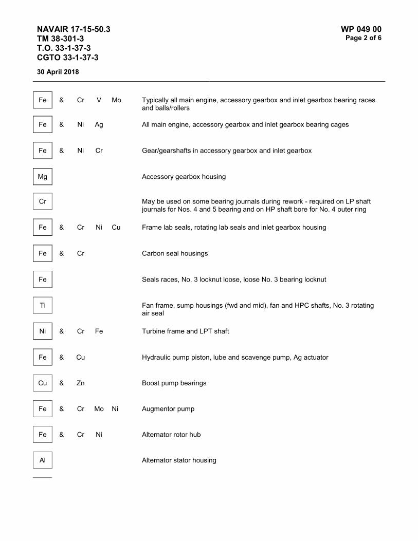
NAVAIR 17-15-50.3 TM 38-301-3 T.O. 33-1-37-3 CGTO 33-1-37-3
WP 049 00 Page 2 of 6
30 April 2018
Fe & Cr V Mo Typically all main engine, accessory gearbox and inlet gearbox bearing races and balls/rollers
Fe & Ni Ag All main engine, accessory gearbox and inlet gearbox bearing cages
Fe & Ni Cr Gear/gearshafts in accessory gearbox and inlet gearbox
Mg Accessory gearbox housing
Cr May be used on some bearing journals during rework - required on LP shaft journals for Nos. 4 and 5 bearing and on HP shaft bore for No. 4 outer ring
Fe & Cr Ni Cu Frame lab seals, rotating lab seals and inlet gearbox housing
Fe & Cr Carbon seal housings
Fe Seals races, No. 3 locknut loose, loose No. 3 bearing locknut
Ti Fan frame, sump housings (fwd and mid), fan and HPC shafts, No. 3 rotating air seal
Ni & Cr Fe Turbine frame and LPT shaft
Fe & Cu Hydraulic pump piston, lube and scavenge pump, Ag actuator
Cu & Zn Boost pump bearings
Fe & Cr Mo Ni Augmentor pump
Fe & Cr Ni Alternator rotor hub
Al Alternator stator housing

NAVAIR 17-15-50.3 TM 38-301-3 T.O. 33-1-37-3 CGTO 33-1-37-3
WP 049 00 Page 3 of 6
30 April 2018
Fe & Si Alternator core laminations
Ti & Fe Loose No. 3 locknut
Fe & Ti Ni Loose No. 3 bearing locking nut
Fe & Ti Loose No. 3 bearing locking nut, frame or shaft wear in forward area of mid sump
Ag & Cu Mg Zn Contaminated with 10W30 automotive oil
RECOMMENDATIONS, DIRECTIONS AND REQUIREMENTS
1. Historically, high or abnormal wear metal levels have been tracked to engine accessory item failures. Main engine bearing failures on the F110 engine are typically caused by spalling, which is detected by Chip detectors. Bearing failures may occur without any indication reflected in the JOAP analysis. Chip detector inspection results and JOAP analysis results may be used together to increase the accuracy of the evaluation process for the F110 engine.
2. Chip detectors shall be inspected when increases in JOAP wear metal concentrations cause concern or when the OAP lab request a Red cap sample. Debris on the chip detector may indicate part distress.
3. When high wear metal concentrations are noted, a sample would be taken from the hydraulic tank servicing port to isolate the wear metal source to either the lube oil or hydraulic components. When the hydraulic system is generating the wear metals, the concentration level will be significantly higher in the hydraulic oil sample. A significant rise in Fe accompanying Ti may indicate a loose No. 3 locknut.
4. When an F110 engine has a wear metal concentration in the high range, or a trend approaching the abnormal limit, the engine shall be placed on surveillance in accordance with T.O. IF-16C-2-70FI-00-11 and T.O. 33-1-37-3.
5. If an engine has been disassembled for inspection due to wear metal concentration limits being exceeded, that engine shall be placed on surveillance in accordance with T.O. IF-16C-2-70FI-00-11 or IF-16CG-70FI-00-11 and T.O. 33-1-37-3.
6. Any wear metal concentration which requires the engine to be placed on surveillance or requires engine maintenance shall be confirmed by analyzing a second sample taken from the suspect engine. The base engine manager shall be notified of any special sample red cap requests and engine surveillance code changes.
7. When an engine is on surveillance, oil filter and chip detector inspections shall be accomplished by the appropriate personnel each time an oil sample is taken. Results will be reported to the OAP laboratory and base engine manager. Again, JOAP analysis and chip detector inspection results shall be used together to effectively evaluate the condition of the F110 engine.

NAVAIR 17-15-50.3 TM 38-301-3 T.O. 33-1-37-3 CGTO 33-1-37-3
WP 049 00 Page 4 of 6
30 April 2018
8. When an F110 engine is on surveillance, oil samples shall be drawn after each flight and analysis results shall be known before the next flight. All aircraft on E code are restricted to the local area.
9. An engine on surveillance may be operated for maintenance or test cell operations as long as samples are taken and analyzed and results received at intervals not to exceed one hour engine operating time. Under no circumstances shall an engine be operated past the one hour time without having the sample results.
10. When an F110 engine is on surveillance, any of the following require maintenance action to correct problem(s) causing the wear metal increases:
a. If any wear metal concentration level moves into a higher range (i.e., marginal to high).
b. The wear metal trend continues to increase.
c. Chips are found on the chip detectors.
d. When a wear metal concentration level is in the abnormal category.
e. When element(s) exceed the abnormal trend limit.
11. Engines with less than 100 flying hours since new may exhibit Fe trending and concentrations that exceed the limits prescribed in the tables. This is due to initial break-in of oil lubricated parts and the cleaning action of the oil which may remove microscopic manufacturing residues. For such engines, the following iron trending and concentration limits apply, provided that all other wear metal concentrations, oil consumption and master chip detector (MCD) inspections are normal/within limits.
a. During the first 25 hours of flight, the maximum acceptable rate of Fe increase is 6 PPM in 10 engine flight hours (EFH), and the maximum acceptable concentration is 19 PPM.
b. Between 25 and 60 flight hours, Fe trending must not exceed 4 PPM in 10 EFH, and the concentration must not exceed 19 PPM.
c. Between 60 and 100 flight hours, Fe trending must not exceed 3 PPM in 10 EFH, and the concentration must not exceed 19 PPM. For any given engine, the rate at which the maximum concentration drops will depend on the rate of oil consumption. Once Fe trending has dropped to 3 PPM or less in 10 EFH, a drain and re-service may be performed to reduce any high concentrations of Fe.
d. Engines exhibiting Fe trend/concentration within these limits shall remain on normal surveillance (Code A). After the engine has accumulated 100 flight hours, the trending and concentration limits defined in the tables must be applied.
12. F110-GE-100 engine maximum allowable consumption is 1.5 half-pints per EOT. Consumption inspection is recommended at every servicing (calculated). If the maximum consumption rate is exceeded, troubleshooting per applicable technical order (2J-F110-3-9, 2J-F110-6-4, 2J-F110-6-13, or 1F-16CJ-70FI-00-11.)
13. F110-GE-100 engine lubrication system attributes differ according to which oil tank is mounted, as follows:

NAVAIR 17-15-50.3 TM 38-301-3 T.O. 33-1-37-3 CGTO 33-1-37-3
WP 049 00 Page 5 of 6
30 April 2018
P/N 1583M89G01 P/N 7127M47G02
Lube Capacity - Full (Half-Pints) 43 45
Volume from “Fill” Line to "Full" Line (Half-Pints) 3 6
POTENTIAL SOURCES OF WEAR METALS
1. Main Bearings or Gearshafts.
a. A sudden increase of Fe may indicate main bearing distress; small amounts of Ag and Ni may accompany the Fe.
b. A moderate increasing trend of Fe may indicate excessive wear of gears and gearshaft splines.
c. For a confirmed significant Ti reading (8-9 PPM for emission), the numbers 1 and 2, and possible number 3 bearing inner races may be turning on the inner race journals.
d. Increasing Cr may indicate the inner race may be spinning on the number 4 and 5 bearing journals.
e. An abnormal rise in Fe may indicate loose No. 3 bearing locking nut; this may be accompanied by rises in Ti or Ni.
2. Accessory Items.
a. Lube and scavenge pump distress may be indicated by increasing trends in Fe and Cu together. Al may accompany the Fe and Cu.
b. Following hydraulic pump replacement, a rise in Cu level may be expected during the break-in period (10-12 engine flight hours (EFH)). This trend will continue to rise during this period. A rise in Cu (3 PPM emission) in 15 EFH may indicate hydraulic pump head port relief valve failure. Troubleshoot per applicable technical order (2J-F100-3-9, 2J-F110-6-4, 2J-F110-6-13, or 1F-16CJ-70FI-00-11 for the F110-GE-100).
c. Boost pump bearing distress may be indicated by increasing trends in Cu and Zn together.
3. Gearbox.
a. Increasing trends in Fe may indicate gearbox problems. Mg and Ag wear metals may accompany the increase in Fe.
b. Chrome plating may be used for repair of gearbox bearing journals. Increasing Cr may indicate the bearing race may be spinning on the journals.
4. Miscellaneous.
a. High Si indicates oil contamination, possibly from the oil servicing cart. The oil servicing cart shall be checked for contamination and, if contamination is confirmed, shall be drained and flushed. The engine

NAVAIR 17-15-50.3 TM 38-301-3 T.O. 33-1-37-3 CGTO 33-1-37-3
WP 049 00 Page 6 of 6
30 April 2018
shall be drained and flushed to remove Si contamination. Post maintenance samples from the engine and oil servicing cart, if applicable, shall be analyzed by the OAP laboratory to assure all Si contamination has been removed.
b. Indications of Pb are not indicative of a need for further troubleshooting. Pb residue is a result of the tube forming process.
c. Increase or abnormal oil levels in Zn or Mo, with no significant accompanying wear metals are not cause for engine removal however, when abnormal trends or levels occur for Zn or Mo, the oil cart shall be checked for contamination.
d. A rise in Ag accompanied by a rise in Zn, Mg or Cu can be an indication that the engine has been contaminated with automotive oil (10W30, 10W40, etc.). Ag, Zn, Cu and Mg should stabilize after the engine has been drained and flushed. An Ag trend without Mg or Zn, or one which does not stabilize after the drain and flush is an indication that an engine bearing is deteriorating. Zn levels may remain high after the 10 flight hours of local operation. This is normal provided there is a general decreasing trend in Zn levels. Automotive oil contamination will not cause significant damage to oil system components. The oil servicing carts should also be inspected for contamination. Carts found to be contaminated should also be drained and flushed.
e, If darkening of the oil occurs, the most immediate concern is overheating of the oil. Oil overheating will generally be evidenced by darkening of the oil, accompanied by a burned oil smell. Black oil may also be an indication of abnormal carbon seal wear.
NOTE For unusual conditions not covered by this technical order or for technical assistance, contact OC-ALC/LPAAT at DSN 336-7714, commercial 405-736-7714.

NAVAIR 17-15-50.3 TM 38-301-3 T.O. 33-1-37-3 CGTO 33-1-37-3
WP 050 00 Page 1 of 6
30 April 2018
TYPE EQUIPMENT Aircraft Engine
MANUFACTURER General Electric
EQUIPMENT/SYSTEM MODEL NUMBER/DESIGNATION
WEAPON SYSTEM PLATFORM(S)
JOAP TYPE EQUIPMENT CODE
F110-GE-129 F-16 FHCA
LUBRICATING OIL MIL-PRF-7808
TECHNICAL AUTHORITY Air Force
STATUS In Use
Table 1 - JOAP ATOMIC EMISSION ROTRODE LIMITS
Fe Ag Al Cr Cu Mg Ni Ti Mo B Si Zn
Abnormal Trend (PPM Increase in 10 hrs)
3 2 2 2 4 2 2 2 2 5 2
Normal Range 0-8 0-3 0-3 0-6 0-12 0-6 0-5 0-5 0-2 0-12 0-2 Marginal Range 9-11 4-5 4-5 7-8 13-16 7-8 6-7 6-7 3 13-15 3 High Range 12-13 6 6 9 17-19 9 8 8 4 16-19 4 Abnormal ≥14 ≥7 ≥7 ≥10 ≥20 ≥10 ≥9 ≥9 ≥5 10 ≥20 ≥5
Elevated boron (B) and/or zinc (Zn) concentrations usually indicate contamination with another oil type, primarily MIL-PRF-2104. Recommend resampling and retesting immediately. If new value exceeds 8.0 PPM, run check with D19-0 to ensure proper instrument function. When proper function is confirmed, report both results and suspected contamination with MIL-PRF-2104 to chain of command, maintenance chief, cognizant engineering authority (Army and Navy only), and other personnel as specified by local written procedures. Recommend flushing and retesting of contaminated pre-oilers, carts, or other reservoirs where contamination is found until both B and Zn concentrations fall below 8.0 PPM. Refer to JOAP Manual Volume 2, WP 021 00 for more information. Recommend segregation of confirmed or suspected contaminated stocks, and submit information (batch no., lot no., MIL-PRF, nature of problem, etc.) on such stocks through the Defense supply deficiency reporting system.
Fe & Cr V Mo Typically all main engine, accessory gearbox and inlet gearbox bearing races and balls/rollers
Fe & Ni Ag All main engine, accessory gearbox and inlet gearbox bearing cages
Fe & Ni Cr Gear/gear shafts in accessory gearbox and inlet gearbox

NAVAIR 17-15-50.3 TM 38-301-3 T.O. 33-1-37-3 CGTO 33-1-37-3
WP 050 00 Page 2 of 6
30 April 2018
Mg Accessory gearbox housing
Cr May be used on some bearing journals during rework - required on LP shaft journals for Nos. 4 and 5 bearing and on HP shaft bore for No. 4 outer ring
Fe & Cr Ni Cu Frame lab seals, rotating lab seals and inlet gearbox housing
Fe & Cr Carbon seal housings
Fe Seals races, No. 3 locknut loose, loose No. 3 bearing locknut, fan frame, sump housings (fwd and mid), fan and HPC shafts, No. 3 rotating air seal
Ni & Cr Fe Turbine frame and LPT shaft
Fe & Cu Hydraulic pump piston, lube and scavenge, pump exhaust nozzle actuators
Cu & Zn Boost pump bearings
Fe & Cr Mo Ni Augmentor pump
Fe & Cr Ni Alternator rotor hub
Al Alternator stator housing
Fe & Si Alternator core laminations
Ti & Fe Loose No. 3 locknut
Fe & Ti Ni Loose No. 3 bearing locking nut
Fe & Ti Loose No. 3 bearing locking nut, frame or shaft wear in forward area of mid sump

NAVAIR 17-15-50.3 TM 38-301-3 T.O. 33-1-37-3 CGTO 33-1-37-3
WP 050 00 Page 3 of 6
30 April 2018
Ag & Cu Mg Zn Contaminated with 10W30 automotive oil
Zn Mo Contaminated with automotive oil
Si Hydraulic pump torque motor servo valve
RECOMMENDATIONS, DIRECTIONS AND REQUIREMENTS
1. Historically, high or abnormal wear metal levels have been tracked to engine accessory item failures. Main engine bearing failures on the F110 engine are typically caused by spalling, which is detected by chip detectors. Bearing failures may occur without any indication reflected in the JOAP analysis. Chip detector inspection results and JOAP analysis results may be used together to increase the accuracy of the evaluation process for the F110 engine.
2. Chip detectors shall be inspected when increase in JOAP wear metal concentrations cause concern or when the OAP lab request a red cap sample. Debris on the chip detector may indicate part distress.
3. When high wear metal concentrations requiring maintenance action are noted, a sample shall be taken from the hydraulic tank servicing port to isolate the wear metal source to either the lube oil or hydraulic components. When the hydraulic system is generating the wear metal, the concentration level will be significantly higher in the hydraulic oil sample. If a significant rise in Fe accompanies Ti, a loose No. 3 locknut may be indicated.
4. An engine shall be placed on surveillance when JOAP Volume 3, WP 003 00 decision making guidelines recommend any code except "A" or "A or B" the engine shall remain on surveillance until either JOAP Volume 3, WP 003 00 recommendation drops to "A" or "A or B", or troubleshooting and correction are required per step 10.
5. If an engine has been disassembled for inspection due to wear metal concentration limits being exceeded, that engine shall be placed on surveillance for 10 EFH.
6. Any wear metal concentration which requires the engine be placed on surveillance or requires engine maintenance shall be confirmed by analyzing a second sample taken from the suspect engine. The base engine manager shall be notified of any special red cap requests and engine surveillance code changes.
7. When an engine is on surveillance, chip detector inspection shall be accomplished by the appropriate personnel each time an oil sample is taken. Oil and hydraulic filters shall be inspected when first placed on surveillance. Results will be reported to the OAP laboratory and base engine manager. JOAP analysis and chip detector inspection results shall be used together to effectively evaluate the condition of the F110 engine.
8. When an F110 engine is on surveillance, oil samples shall be drawn after each flight and analysis results shall be known before the next flight. Flying shall be restricted to the local area, only if JOAP Volume 3, WP 003 00 recommends Code E or higher.

NAVAIR 17-15-50.3 TM 38-301-3 T.O. 33-1-37-3 CGTO 33-1-37-3
WP 050 00 Page 4 of 6
30 April 2018
9. Engines under surveillance maybe operated for maintenance or test cell operation for up to 2 hours engine operating time (EOT) before a sample must be taken, The engine may be operated for additional 2 hours EOT before the results of the first and second samples must be known.
10. Troubleshooting and corrective maintenance actions to correct the source of wear metals must be taken when JOAP Volume 3, WP 003 00 or OAP laboratory recommends code "H" or higher.
11. Engines with less than 100 flying hours since new may exhibit Fe trending and concentrations that exceed the limits prescribed in the tables. This is due to initial break-in of oil lubricated parts and the cleaning action of the oil which may remove microscopic manufacturing residues. For such engines, the following iron trending and concentration limits apply, provided that all other wear metal concentrations, oil consumption and master chip detector (MCD) inspections are normal/within limits.
a. During the first 25 hours of flight, the maximum acceptable rate of Fe increase is 6 PPM in 10 engine flight hours (EFH), and the maximum acceptable concentration is 19 PPM.
b. Between 25 and 60 flight hours, Fe trending must not exceed 4 PPM in 10 EFH, and the concentration must not exceed 19 PPM.
c. Between 60 and 100 flight hours, Fe trending must not exceed 3 PPM in 10 EFH, and the concentration must not exceed 19 PPM. For any given engine, the rate at which the maximum concentration drops will depend on the rate of oil consumption. Once Fe trending has dropped to 3 PPM or less in 10 EFH, a drain and re-service may be performed to reduce any high concentrations of Fe.
d. Engines exhibiting Fe trend/concentration within these limits shall remain on normal surveillance (Code A). After the engine has accumulated 100 flight hours, the trending and concentration limits defined in the tables must be applied.
12. F110-GE-129 Engine maximum allowable consumption is 1.5 half pints per EOT. Consumption inspection is recommended at every servicing (calculated). If the maximum consumption rate is exceeded, troubleshoot per applicable technical order (2J-F110-3-9, 2J-F110-6-4, 2J-F110-6-13, or 1F-16CJ-70FI-00-11).
13. For effect of oil servicing dilution the F110 typical lube system operating volume is 5 gallons.
POTENTIAL SOURCES OF WEAR METALS
1. Main Bearings or Gearshafts.
a. A sudden increase of Fe may indicate main bearing distress; small amounts of Ag and Ni may accompany the Fe.
b. A moderate increasing trend of Fe may indicate excessive wear of gears and gearshaft splines.
c. For a confirmed significant Ti reading (8-9 PPM for emission), the numbers 1 and 2, and possible number 3 bearing inner races may be turning on the inner race journals.
d. Increasing Cr may indicate the inner race may be spinning on the number 4 and 5 bearing journals.

NAVAIR 17-15-50.3 TM 38-301-3 T.O. 33-1-37-3 CGTO 33-1-37-3
WP 050 00 Page 5 of 6
30 April 2018
e. An abnormal rise in Fe may indicate loose No. 3 bearing locking nut: This may be accompanied by rises in Ti or Ni.
2. Accessory Items.
a. Lube and scavenge pump distress may be indicated by increasing trends in Fe and Cu together. Al may accompany the Fe and Cu.
b. Following hydraulic pump replacement, a rise in Cu level may be expected during the break-in period (10-12 engine flight hours (EFH)). his trend will continue to rise during this period. A rise in Cu (3 PPM emission) in 15 EFH may indicate hydraulic pump head port relief valve failure. Troubleshoot per applicable technical order (2J-F100-3-9, 2J-F110-6-4, 2J-F110-6-13, or IF-16CJ-70FI-00-11 for the F110-GE-129 engine).
c. Boost pump bearing distress may be indicated by increasing trends in Cu and Zn together.
3. Gearbox.
a. Increasing trends in Fe may indicate gearbox problems. Mg and Ag wear metals may accompany the increase in Fe.
b. Chrome plating may be used for repair of gearbox bearing journals. Increasing Cr may indicate the bearing race may be spinning on the journals.
4. Miscellaneous.
a. High Si indicates oil contamination, possibly from the oil servicing cart, engine wash chemicals, or hydraulic pump torque motor servo valve damping fluid. High Si content in oil sampled from the Hydraulic Pump with Normal Range Si content in the oil sampled from the Lube and Scavenge Pump oil would indicate leakage of the Hydraulic Pump Torque Motor Servo Valve damping solution, Hydraulic Pump replacement is recommended. The oil-servicing cart should be checked for contamination and, if contamination is confirmed, shall be drained and flushed. The engine shall be drained and flushed to remove Si contamination. Post maintenance samples from the engine and oil-servicing cart, if applicable, shall be analyzed by the OAP laboratory to assure all Si contamination has been removed.
b. Indications of Pb are not indicative of a need for further troubleshooting. Pb residue is a result of the tube forming process.
c. Increase or abnormal oil levels in Zn or Mo, with no significant accompanying wear metals are not cause for engine removal. However, when abnormal trends or levels occur for Zn or Mo, the oil cart shall be checked for contamination.

NAVAIR 17-15-50.3 TM 38-301-3 T.O. 33-1-37-3 CGTO 33-1-37-3
WP 050 00 Page 6 of 6
30 April 2018
d. A rise in Ag accompanied by a rise in Zn, Mg or Cu can be an indication that the engine has been contaminated with automotive oil (10W30, 10W40, etc.). Ag, Zn, Cu and Mg should stabilize after the engine has been drained and flushed. An Ag trend without Mg or Zn, or one which does not stabilize after the drain and flush is an indication that an engine bearing is deteriorating. Zn levels may remain high after the 10 flight hours of local operation. This is normal provided there is a general decreasing trend in Zn levels. Automotive oil contamination will not cause significant damage to oil system components. The oil servicing carts should also be inspected for contamination. Carts found to be contaminated should also be drained and flushed.
e. If darkening of the oil occurs, the most immediate concern is overheating of the oil. Oil overheating will generally be evidenced by darkening of the oil, accompanied by a burned oil smell. Black oil may also be an indication of abnormal carbon seal wear.
NOTE
For technical assistance, contact ASC/LPPH at DSN 785-7869 or COMM (937) 235-7869.

NAVAIR 17-15-50.3 TM 38-301-3 T.O. 33-1-37-3 CGTO 33-1-37-3
WP 051 00 Page 1 of 4
30 April 2018
TYPE EQUIPMENT Aircraft Engine
MANUFACTURER General Electric
EQUIPMENT/SYSTEM MODEL NUMBER/DESIGNATION
WEAPON SYSTEM PLATFORM(S)
JOAP TYPE EQUIPMENT CODE
F110-GE-400 F-14 FHBA
LUBRICATING OIL MIL-PRF-23699
TECHNICAL AUTHORITY NAVAIR
STATUS Aircraft retired. WP retained for reference.
Table 1 - JOAP ATOMIC EMISSION ROTRODE LIMITS
Fe Ag Al Cr Cu Ni Ti Mo B Si Zn
Abnormal Trend (PPM Increase in 10 Hrs)
3 2 2 2 4 2 2 2 2
Normal Range 0-8 0-3 0-3 0-6 0-12 0-5 0-5 0-2 0-2 Marginal Range 9-11 4-5 4-5 7-8 13-16 6-7 6-7 3 3 High Range 12-13 6 6 9 17-19 8 8 4 4 Abnormal ≥14 ≥7 ≥7 ≥10 ≥20 ≥9 ≥9 ≥5 10 10 ≥5+
Elevated boron (B) and/or zinc (Zn) concentrations usually indicate contamination with another oil type, primarily MIL-PRF-2104. Recommend resampling and retesting immediately. If new value exceeds 8.0 PPM, run check with D19-0 to ensure proper instrument function. When proper function is confirmed, report both results and suspected contamination with MIL-PRF-2104 to chain of command, maintenance chief, cognizant engineering authority (Army and Navy only), and other personnel as specified by local written procedures. Recommend flushing and retesting of contaminated pre-oilers, carts, or other reservoirs where contamination is found until both B and Zn concentrations fall below 8.0 PPM. Refer to JOAP Manual Volume 2, WP 021 00 for more information. Recommend segregation of confirmed or suspected contaminated stocks, and submit information (batch no., lot no., MIL-PRF, nature of problem, etc.) on such stocks through the Defense supply deficiency reporting system.

NAVAIR 17-15-50.3 TM 38-301-3 T.O. 33-1-37-3 CGTO 33-1-37-3
WP 051 00 Page 2 of 4
30 April 2018
Elevated silicon (Si) concentration usually indicates contamination with soil, sand, or dust. If aluminum (Al) is also elevated, this suggests the presence of clay or soil. Recommend resampling and retesting immediately. If new value exceeds 8.0 PPM, run check with D19-0 to ensure proper instrument function. When proper function is confirmed, report both results and suspected contamination with soil, sand, or dust to chain of command, maintenance chief, cognizant engineering authority (Army and Navy only), and other personnel as specified by local written procedures. Recommend flushing and retesting of contaminated pre-oilers, carts, or other reservoirs where contamination is found until silicon concentration falls below 8.0 PPM. Refer to JOAP Manual Volume 2, WP 021 00 for more information. Recommend segregation of confirmed or suspected contaminated stocks, and submit information (batch no., lot no., MIL-PRF, nature of problem, etc.) on such stocks through the Defense supply deficiency reporting system.
Fe & Cr V Mo Typical all main engine, accessory gearbox and inlet gearbox bearing races and balls/rollers
Fe & Ni Ag All main engine, accessory gearbox and inlet gearbox bearing cages
Fe & Ni Cr Gear/gearshafts in accessory gearbox and inlet gearbox; aft lube/scavenge pump coupling shaft
Al Accessory gearbox housing, alternator stator housing
Cr May be used on some bearing journals during rework - required on LP shaft journals for Nos. 4 and 5 bearing and on HP shaft bore for No. 4 outer ring
Fe & Cr Ni Cu Frame lab seals, rotating lab seals and inlet gearbox housing
Fe & Cr Carbon seal housings
Fe Seal races
Ti Fan frame, sump housings (fwd and mid), fan and HPC shafts, No. 3 rotating air seal
Ni & Cr Fe Turbine frame and LPT shaft
Fe & Cu Hydraulic pump piston, lube and scavenge pump, A8 actuators
Cu & Zn Boost pump bearings

NAVAIR 17-15-50.3 TM 38-301-3 T.O. 33-1-37-3 CGTO 33-1-37-3
WP 051 00 Page 3 of 4
30 April 2018
Fe & Cr Mo Ni Augmentor fuel pump
Fe & Cr Ni Alternator rotor hub
Fe & Si Alternator core laminations
Si Hydraulic pump torque motor servo valve
NOTES
1. A sudden increase (9-11 PPM for emission) of Fe may indicate main bearing distress; small amounts or Ag may accompany the Fe.
2. A moderate increasing trend of Fe may indicate excessive wear of gears and gearshaft splines.
3. For a confirmed significant (8-9 PPM) Ti reading, the Nos. 1, 2 and possible No. 3 bearing inner races may be turning on the inner race journals.
4. Lube and scavenge pump bearing distress may be indicated by trends in Fe and Cu together. Al may accompany the Fe and Cu.
5. Increasing trends in Fe may indicate gearbox problems. Mg and Ag wear metals may accompany the increase in Fe.
6. Cr is used on Nos. 4 and 5 bearing journals and may be used for repair of gearbox bearing journals. Increasing Cr may indicate inner race spinning on the journals.
7. Inspect chip detectors when increases in JOAP wear metals cause concern; debris in the chip detector may indicate part distress.
8. The main engine bearings may fail without indication reflected in the JOAP analysis. Spalling of these bearings is detected by chip detectors.

NAVAIR 17-15-50.3 TM 38-301-3 T.O. 33-1-37-3 CGTO 33-1-37-3
WP 051 00 Page 4 of 4
30 April 2018
9. High Si indicates oil contamination, possibly from the oil servicing cart, engine wash chemicals, or hydraulic pump torque motor servo valve damping fluid. High Si content in oil sampled from the Hydraulic Pump with Normal Range Si content in the oil sampled from the Lube and Scavenge Pump oil would indicate leakage of the Hydraulic Pump Torque Motor Servo Valve damping solution, Hydraulic Pump replacement is recommended. The oil-servicing cart should be checked for contamination and, if contamination is confirmed, shall be drained and flushed. The engine shall be drained and flushed to remove Si contamination. Post maintenance samples from the engine and oil-servicing cart, if applicable, shall be analyzed by the OAP laboratory to assure all Si contamination has been removed.
10. Abnormal trend or high level of Zn is not indicative of a failure unless accompanied with an abnormal trend or high level in Cu (fuel boost pump bearings).
11. Abnormal trend or high level or Mo is not indicative of a failure unless accompanied with an abnormal trend or high level in Fe and Cr.
12. When high levels of Fe or Cu are noted, additional oil samples should be taken from the hydraulic drain port on the oil tank. This may isolate the source of wear metal to either the lube system or hydraulic system. When the hydraulic system is generating wear metal, the wear metal concentration in the hydraulic oil sample will be significantly higher than the wear metal concentration in the lube oil sample.

NAVAIR 17-15-50.3 TM 38-301-3 T.O. 33-1-37-3 CGTO 33-1-37-3
WP 052 00 Page 1 of 4
30 April 2018
TYPE EQUIPMENT Aircraft Engine
MANUFACTURER General Electric
EQUIPMENT/SYSTEM MODEL NUMBER/DESIGNATION
WEAPON SYSTEM PLATFORM(S)
JOAP TYPE EQUIPMENT CODE
F118-GE-100 B-2 FKAA
LUBRICATING OIL MIL-PRF-7808
TECHNICAL AUTHORITY Air Force
STATUS In Use
Table 1 - JOAP ATOMIC EMISSION ROTRODE LIMITS
Fe Ag Al Cr Cu Mg Ni Ti Mo B Si Zn
Abnormal Trend (PPM Increase in 10 Hrs)
3 2 2 2 4 2 2 2 2 5 2
Normal Range 0-8 0-3 0-3 0-6 0-12 0-6 0-5 0-5 0-2 0-12 0-2 Marginal Range 9-11 4-5 4-5 7-8 13-16 7-8 6-7 6-7 3 13-15 3 High Range 12-13 6 6 9 17-19 9 8 8 4 16-19 4 Abnormal ≥14 ≥7 ≥ ≥10 ≥20 ≥10 ≥9 ≥9 ≥5 10 ≥20 ≥5
Elevated boron (B) and/or zinc (Zn) concentrations usually indicate contamination with another oil type, primarily MIL-PRF-2104. Recommend resampling and retesting immediately. If new value exceeds 8.0 PPM, run check with D19-0 to ensure proper instrument function. When proper function is confirmed, report both results and suspected contamination with MIL-PRF-2104 to chain of command, maintenance chief, cognizant engineering authority (Army and Navy only), and other personnel as specified by local written procedures. Recommend flushing and retesting of contaminated pre-oilers, carts, or other reservoirs where contamination is found until both B and Zn concentrations fall below 8.0 PPM. Refer to JOAP Manual Volume 2, WP 021 00 for more information. Recommend segregation of confirmed or suspected contaminated stocks, and submit information (batch no., lot no., MIL-PRF, nature of problem, etc.) on such stocks through the Defense supply deficiency reporting system.

NAVAIR 17-15-50.3 TM 38-301-3 T.O. 33-1-37-3 CGTO 33-1-37-3
WP 052 00 Page 2 of 4
30 April 2018
Fe & V Mo Typical all main engine, accessory gearbox and inlet gearbox bearing races and balls/rollers
Fe & Ni Ag All main engine, accessory gearbox and inlet gearbox bearing cages
Fe & Ni Cr Gear/gearshafts in accessory gearbox and inlet gearbox; aft lube/scavenge pump coupling shaft
Cr May be used on some bearing journals during rework - required on LP shaft journals for Nos. 4 and 5 bearing and on HP shaft bore for No. 4 outer ring
Fe & Cr Ni Cu Frame lab seals, rotating lab seals and inlet gearbox housing
Fe & Cr Carbon seal housings
Fe Seal races, loose No. 3 bearing locking nut
Ti Fan frame, sump housings (fwd and mid), fan and HPC shafts, No. 3 rotating air seal
Ni & Cr Fe Turbine frame and LPT shaft
Fe & Cu Lube supply and scavenge pump
Fe & Cr Ni Alternator rotor hub
Al Alternator stator housing and accessory gearbox housing
Fe & Si Alternator core laminations
Fe & Ti Ni Loose No. 3 bearing locking nut
Fe & Ti Loose No. 3 bearing locking nut, frame or shaft wear in forward or mid sump
NAVAIR 17-15-50.3 TM 38-301-3 T.O. 33-1-37-3 CGTO 33-1-37-3
WP 052 00 Page 3 of 4
30 April 2018
NOTES
1. Historically, high or abnormal wear metal levels have been tracked to engine accessory item failures. Main engine bearing failures on the F-118 engine are typically caused by spalling which is detected by the quantitative debris monitor QDM. Bearing failures may occur without any indication reflected in the JOAP analysis. QDM inspection and JOAP analysis results may be used together to increase the accuracy of the evaluation process for the F-118 engine.
2. QDM shall be inspected when increases in JOAP wear metal concentrations cause concern or when the OAP lab requests a special red cap sample. Debris on the QDM may indicate part distress.
POTENTIAL SOURCES OF WEAR METAL
1. Main Bearings or Gearboxes.
a. A sudden increase of iron Fe may indicate main bearing distress, small amounts of silver Ag and nickel Ni may accompany the Fe.
b. A moderate increasing trend of Fe may indicate excessive wear of gears and gear shafts splines.
c. For a confirmed significant titanium Ti readings, 8-9 PPM for emission rotrode, the numbers 1 and 2, and possibly number 3 bearing inner races may be turning on the inner race journals.
NOTE
If a significant rise in Fe accompanies Ti, this may indicate a loose number 3 locknut.
d. Increasing chromium Cr may indicate the inner race may be spinning on the numbers 4 and 5 bearing journals.
e. An abnormal rise in Fe may be accompanied by rises in Ti or Ni.
2. Accessory Items.
a. Lube and scavenge pump distress may be indicated by increasing trends in Fe and copper Cu together. Al may accompany the Fe and Cu.
3. Gearbox.
a. Increasing trends in Fe may indicate gearbox problems. Al and Ag wear metals may accompany the increase in Fe.
4. Miscellaneous.
a. High silicon Si indicates oil contamination, possibly from the oil servicing cart. The oil servicing cart and engine shall be checked from contamination and, if contamination is confirmed, both oil servicing cart and
NAVAIR 17-15-50.3 TM 38-301-3 T.O. 33-1-37-3 CGTO 33-1-37-3
WP 052 00 Page 4 of 4
30 April 2018
engine shall be drained and flushed to remove the Si contamination. Post maintenance samples from the engine and oil servicing cart, if applicable shall, be analyzed by the OAP laboratory personnel to ensure all Si contamination has been removed.
b. Indications of lead Pb are not indicative of a need for further troubleshooting. Pb residue is a result of the tube forming process.
c. Increase or abnormal PPM levels of zinc Zn, Mg, or molybdenum Mo, with no significant accompanying wear metals are not cause for engine removal, however, when abnormal trends or levels occur for Zn, Mg, or Mo, the oil cart shall be checked for contamination. The engine shall be drained and flushed to remove Zn, Mg, or Mo contamination. Post maintenance samples from the engine and oil servicing cart, if applicable, shall be analyzed by the OAP laboratory personnel to ensure all contamination has been removed.

NAVAIR 17-15-50.3 TM 38-301-3 T.O. 33-1-37-3 CGTO 33-1-37-3
WP 053 00 Page 1 of 4
30 April 2018
TYPE EQUIPMENT Aircraft Engine
MANUFACTURER General Electric
EQUIPMENT/SYSTEM MODEL NUMBER/DESIGNATION
WEAPON SYSTEM PLATFORM(S)
JOAP TYPE EQUIPMENT CODE
F118-GE-101 U-2S EMAC
LUBRICATING OIL MIL-PRF-7808
TECHNICAL AUTHORITY Air Force
STATUS In Use
Table 1 - JOAP ATOMIC EMISSION ROTRODE LIMITS
Fe Ag Al Cr Cu Mg Ni Ti Mo B Si Zn
* Abnormal Trend (PPM Increase in 10 Hrs)
3 2 2 2 4 2 2 2 2 5 2
Normal Range 0-8 0-3 0-3 0-6 0-12 0-6 0-5 0-5 0-2 0-12 0-2 Marginal Range 9-11 4-5 4-5 7-8 13-16 7-8 6-7 6-7 3 13-15 3 High Range 12-13 6 6 9 17-19 9 8 8 4 16-19 4 Abnormal ≥14 ≥7 ≥7 ≥10 ≥20 ≥10 ≥9 ≥9 ≥5 10 ≥20 5+ NOTE: * If the calculated PPM trend value is equal to or greater than the trend PPM value limit, the engine has an
abnormal trend.
Elevated boron (B) and/or zinc (Zn) concentrations usually indicate contamination with another oil type, primarily MIL-PRF-2104. Recommend resampling and retesting immediately. If new value exceeds 8.0 PPM, run check with D19-0 to ensure proper instrument function. When proper function is confirmed, report both results and suspected contamination with MIL-PRF-2104 to chain of command, maintenance chief, cognizant engineering authority (Army and Navy only), and other personnel as specified by local written procedures. Recommend flushing and retesting of contaminated pre-oilers, carts, or other reservoirs where contamination is found until both B and Zn concentrations fall below 8.0 PPM. Refer to JOAP Manual Volume 2, WP 021 00 for more information. Recommend segregation of confirmed or suspected contaminated stocks, and submit information (batch no., lot no., MIL-PRF, nature of problem, etc.) on such stocks through the Defense supply deficiency reporting system.
Fe & Cr V Mo Typical all main engine, accessory gearbox and inlet gearbox bearing races and balls/rollers
Fe & Ni Ag All main engine, accessory gearbox and inlet gearbox bearing cages
Fe & Ni Cr Gear/gearshafts in accessory gearbox and inlet gearbox

NAVAIR 17-15-50.3 TM 38-301-3 T.O. 33-1-37-3 CGTO 33-1-37-3
WP 053 00 Page 2 of 4
30 April 2018
Cr May be used on some bearing journals during rework - required on LP shaft journals for Nos. 4 and 5 bearing and on HP shaft bore for No. 4 outer ring
Fe & Cr Ni Cu Frame lab seals, rotating lab seals and inlet gearbox housing
Fe & Cr Carbon seal housings
Fe Seal races, loose No. 3 bearing locking nut
Ti Fan frame, sump housings (fwd and mid), fan and HPC shafts, No. 3 rotating air seal
Ni & Cr Fe Turbine frame and LPT shaft
Fe & Cu Lube supply and scavenge pump
Fe & Cr Ni Alternator rotor hub
Al Alternator stator housing, accessory gearbox housing
Fe & Si Alternator core laminations
Fe & Ti Ni Loose No. 3 bearing locking nut
Fe & Ti Loose No. 3 bearing locking nut, frame or shaft wear in forward or mid sump
Ag & Cu Mg Zn Contaminated with 10W30 automotive oil
RECOMMENDATIONS, DIRECTIONS AND REQUIREMENTS
1. Historically, high or abnormal wear metal levels have been tracked to engine accessory item failures. Main engine bearing failures are typically caused by spalling, which is detected by chip detectors. Bearing failures may occur without any indication reflected in the JOAP analysis. Chip detector inspection results and JOAP analysis results may be used together to increase the accuracy of the evaluation process.
2. Chip detectors shall be inspected when increases in the JOAP wear metal concentrations cause concern or when the OAP lab requests a special sample. Debris on the chip detector may indicate part distress.
3. When an engine has a wear metal concentration in the high range, or a trend approaching the abnormal limit, the engine shall be placed on surveillance with T.O. U-2S-2-4.
4. If an engine has been disassembled for inspection due to wear metal concentration limits being exceeded, that engine shall be placed on surveillance in accordance with T.O. U-2S-2-4.

NAVAIR 17-15-50.3 TM 38-301-3 T.O. 33-1-37-3 CGTO 33-1-37-3
WP 053 00 Page 3 of 4
30 April 2018
5. Any wear metal concentration which requires the engine to be placed on surveillance or requires engine maintenance shall be confirmed by analyzing a second sample taken from the suspect engine. The base engine manager shall be notified of any special sample requests and engine surveillance code changes.
6. When an engine is on surveillance, oil filter and chip detector inspections shall be accomplished by the appropriate personnel each time an oil sample is taken. Results will be reported to the OAP laboratory and base engine manager. Again, JOAP analysis and chip detector inspection results shall be used together to effectively evaluate the condition of the engine.
7. When an engine is on surveillance, oil samples shall be drawn after each flight and analysis results shall be known before the next flight. All flying is restricted to the local area.
8. An engine on surveillance may be operated for maintenance or test cell operations as long as samples are taken and analyzed and results received at intervals not to exceed one hour engine operating time. Under no circumstances shall an engine be operated past the one hour time without having the sample results.
9. When an engine is on surveillance, any of the following require maintenance action to correct the problem(s):
a. If any wear metal concentration level moves into the higher range (i.e. marginal to high).
b. The wear metal trend continues to increase.
c. Chips are found on the chip detector.
d. When a wear metal concentration level is in the abnormal category.
e. When element(s) exceed the abnormal trend limit.
10. Engines with less than 100 hours engine operating time since new may typically increase into the marginal or high range for Fe due to initial break-in of seals, etc. However, the Fe reading is not indicative of actual component failure, effective JOAP analysis and chip detector inspections are essential. If all other wear metals concentrations are normal, the Fe trend is normal and chip detector inspection is normal, then the engine may be returned to normal surveillance.
11. F118-GE-101 engine maximum allowable consumption is 0.10 gallons per hour. Consumption inspection is recommended at every servicing (calculated). If maximum consumption rate is exceeded, troubleshoot per applicable technical order U-2S-2-4.
POTENTIAL SOURCES OF WEAR METALS
1. Main Bearings or Gearshafts.
a. A sudden increase of Fe may indicate main bearing distress, small amounts of Ag and Ni may accompany the Fe.
b. A moderate increasing trend of Fe may indicate excessive wear of gears and gearshaft splines.
c. For a confirmed significant Ti reading (8-9 PPM), the numbers 1 and 2, and possibly number 3 bearing inner races may be turning on the inner race journals.
NAVAIR 17-15-50.3 TM 38-301-3 T.O. 33-1-37-3 CGTO 33-1-37-3
WP 053 00 Page 4 of 4
30 April 2018
d. Increasing Cr may indicate the inner race may be spinning on the numbers 4 and 5 bearing journals.
e. An abnormal rise in Fe may indicate a loose No. 3 bearing locking nut; this may be accompanied by rises in Ti or Ni.
2. Accessory Items. Lube and scavenge pump distress may be indicated by increasing trends in Fe and Cu together. Al may accompany the Fe and Cu.
3. Gearbox.
a. Increasing trends in Fe may indicate gearbox problems. Al and Ag wear metals may accompanying the increase in Fe.
b. Chrome plating may be used for repair of gearbox bearing journals. Increasing Cr may indicate the bearing race may be spinning on the journals.
4. Miscellaneous.
a. High Si indicates oil contamination, possibly from the oil servicing cart. The oil servicing cart shall be checked for contamination and, if contamination is confirmed, shall be drained and flushed. The engine shall be drained and flushed to remove Si contamination. Post maintenance samples from the engine and oil servicing cart, if applicable, shall be analyzed by the OAP laboratory to assure all Si contamination has been removed.
b. Indications of Pb are not indicative of a need for further troubleshooting. Pb residue is a result of the tube forming process.
c. Increases or abnormal levels of Zn or Mo, with no significant accompanying wear metals are not cause for engine removal. However, when abnormal trends or levels occur for Zn or Mo, the oil cart shall be checked for contamination.
d. A rise in Ag accompanied by a rise in Zn, Mg, or Cu can be an indication that the engine has been contaminated with automotive oil (10W30, 10W40, etc.). Ag, Zn, Cu, and Mg should stabilize after the engine has been drained and flushed. An Ag trend without Mg or Zn, or one which does not stabilize after the drain and flush is an indication that an engine bearing is deteriorating. Zn levels may remain high after the 10 flight hours of local operation. This is normal provided there is a general decreasing trend in Zn levels. Automotive oil contamination will not cause significant damage to oil system components The oil servicing carts should also be inspected for contamination. Carts found to be contaminated should also be drained and flushed.
e. If darkening of the oil occurs, the most immediate concern is overheating of the oil. Oil overheating will generally be evidenced by darkening of the oil, accompanied by a burned oil smell. Black oil may also be an indication of abnormal carbon seal wear.

NAVAIR 17-15-50.3 TM 38-301-3 T.O. 33-1-37-3 CGTO 33-1-37-3
WP 054 00 Page 1 of 8
30 April 2018
TYPE EQUIPMENT Aircraft Engine
MANUFACTURER Pratt & Whitney
EQUIPMENT/SYSTEM MODEL NUMBER/DESIGNATION
WEAPON SYSTEM PLATFORM(S)
JOAP TYPE EQUIPMENT CODE
F119-PW-100A F-22 FRAA
F119-PW-614C F-22 FRCA
F119-PW-611C F-22 FRBA
LUBRICATING OIL MIL-PRF-7808
TECHNICAL AUTHORITY Air Force F119 Propulsion Engineering Team
STATUS In Use
Table 1 - JOAP ATOMIC EMISSION ROTRODE LIMITS
Fe Ag Al Cr Cu Mg Ni Ti Si B Zn
Abnormal Trend (PPM Increase in 10 Hrs)
3 2 3 2 3 2 2 2 N/A
Normal Range 0-5 0-2 0-5 0-4 0-4 0-4 0-4 0-1 0-10 Marginal Range 6-7 N/A 6-7 5 5-7 5 5 N/A N/A High Range 8-9 3 8-9 6 8-9 6 6 2* N/A Abnormal ≥10 ≥4 ≥10 ≥7 ≥10 ≥7 ≥7 ≥3 ≥10 10 10
* Ti High Range exceedance: If three of the previous ten Ti readings are 2 PPM or higher, or if one Ti reading is 3 PPM or higher, proper engine personnel shall be notified immediately that the main fuel pump (MFP) and the oil must be replaced. See appropriate manual FRC in step 2 below. If only one or two readings are 2 PPM, no action is necessary.
Elevated boron (B) and/or zinc (Zn) concentrations usually indicate contamination with another oil type, primarily MIL-PRF-2104. Recommend resampling and retesting immediately. If new value exceeds 8.0 PPM, run check with D19-0 to ensure proper instrument function. When proper function is confirmed, report both results and suspected contamination with MIL-PRF-2104 to chain of command, maintenance chief, cognizant engineering authority (Army and Navy only), and other personnel as specified by local written procedures. Recommend flushing and retesting of contaminated pre-oilers, carts, or other reservoirs where contamination is found until both B and Zn concentrations fall below 8.0 PPM. Refer to JOAP Manual Volume 2, WP 021 00 for more information. Recommend segregation of confirmed or suspected contaminated stocks, and submit information (batch no., lot no., MIL-PRF, nature of problem, etc.) on such stocks through the Defense supply deficiency reporting system.

NAVAIR 17-15-50.3 TM 38-301-3 T.O. 33-1-37-3 CGTO 33-1-37-3
WP 054 00 Page 2 of 8
30 April 2018
F119 DECISION MAKING GUIDELINES
1. Teardown maintenance for the F119 is directed within the F-22 Integrated Maintenance Information System (IMIS) by Advanced Engine Failure Resolution (AEFR).
2. Manual JOAP Fault Report Codes (FRCs) entered in the New Failures Screen within the Process Failure Data application are utilized to create a JCN that will direct the appropriate engine teardown maintenance. Direct the appropriate maintenance personnel to enter one of the FRCs listed below. If the engine is to be removed from the aircraft for maintenance, enter the FRC after the removal has been documented in IMIS.
a. Manual JOAP FRCs: X=1 for left engine, 2 for right engine, 0 for uninstalled. Fe - 7900x3204 observed JOAP iron (Fe) beyond limits Ag - 7900x3208 observed JOAP silver (Ag) beyond limits Al - 7900x3201 observed JOAP aluminum (Al) beyond limits Cr - 7900x3202 observed JOAP chromium (Cr) beyond limits Cu - 7900x3203 observed JOAP copper (Cu) beyond limits Mg - 7900x3205 observed JOAP magnesium (Mg) beyond limits Ni - 7900x3206 observed JOAP nickel (Ni) beyond limits Ti - 7900x3209 observed JOAP titanium (Ti) beyond limits Si - 7900x3207 observed JOAP silicon (Si) beyond limits
3. Any sample value which requires the engine to be placed under surveillance or requires teardown shall be confirmed by a reburn. Proper engine personnel shall be notified immediately if the reburn confirms that surveillance or teardown is required. When an engine is put on surveillance, request for oil filter and chip detector inspection will be made. When an engine is on surveillance, all chip detectors are to be checked each time an oil sample is taken.
4. When an F119 engine is on surveillance, oil samples must be drawn after each flight and analysis results must be known before the next flight. During ground or test cell operation of an engine on surveillance, oil samples must be drawn at intervals no longer than one hour total operating time. After an oil sample is drawn, the engine may not be run for more than one hour before oil analysis results are available.
5. The main engine bearings may fail without indication reflected in the JOAP analysis. Spalling of these bearings is detected by chip detectors.
6. Engine teardown or surveillance is required for any of the following
a. Any wear metal exceeds the abnormal limit. Teardown is required. Enter the manual FRC for the appropriate JOAP wear metal on the New Failures screen within the Process Failure Data application in IMIS. The JCN created from this FRC will direct the appropriate maintenance.
b. Wear metal increase by the value of their abnormal trend within a 10 hour engine operating period (total operating time). Surveillance is required for a 10 hour total operating time period.
c. While on surveillance for an abnormal JOAP Fe trend, Fe increases above the value that caused surveillance by any amount. Teardown is required. Enter manual FRC 7900X3204 “observed JOAP iron (Fe) beyond limits.”
d. Ti increases by the value of the abnormal trend within a 10 hour engine operating period (total operating

NAVAIR 17-15-50.3 TM 38-301-3 T.O. 33-1-37-3 CGTO 33-1-37-3
WP 054 00 Page 3 of 8
30 April 2018
time). Proper engine personnel shall be notified immediately that the Main Fuel Pump and the oil must be replaced prior to surveillance. While on surveillance for Ti, Ti increases above any other sample taken during surveillance by the abnormal trend value. Teardown is required. Enter manual FRC 7900X3209 “observed JOAP titanium (Ti) beyond limits.”
e. Fe increases by the single sample jump limit (3 PPM or more) between any two consecutive samples, Teardown is required. Enter manual FRC 7900X3204 “observed JOAP iron (Fe) beyond limits.”
f. All engines which have been disassembled for inspection due to Fe limits being exceeded are to be placed on surveillance for 10 hours total operating time following repair.
7. When silicon (Si) reaches or exceeds 10 PPM in any two consecutive samples, the customer will perform F-22 IMIS task "test engine – perform oil contamination check run" (LCN A720000) or suitable drain and flush procedure.
8. If lead (Pb) or molybdenum (Mo) exceed 50 PPM, recommend suitable drain and flush procedure. No action is required for levels below 50 PPM.
9. Sodium (Na) or Tin (Sn) at levels exceeding 25 PPM may be indicative of oil cart contamination. Recommend suitable drain and flush procedure and check the servicing carts for contamination.
WEAR METAL SOURCES - Fe and Ti are significant wear metals in this engine.
1. Fe
- No. 1, 2, 3, 4, and 5 mainshaft balls/roller bearings (including races and rolling elements)
- Front, mid, and rear compartments
- Upper towershaft pinion gear/bull gear - mid compartment
- Upper towershaft ball/roller bearings - mid compartment
- Accessory ball/roller bearings - gearbox
- No. 3 bearing inner ring spinning on the bull gear – mid compartment
- Carbon seal runners - front, mid, and rear compartments
- Gear rotor wear - main oil pump
2. Ag
- Mainshaft, upper towershaft, and accessory bearing cages (silver plated) - gearbox, front, mid, and rear components
- No. 4 and 5 bearing nuts (silver plated) - rear compartment
- Upper towershaft pinion gear and gearbox spiral bevel gear (silver flash) - mid compartment

NAVAIR 17-15-50.3 TM 38-301-3 T.O. 33-1-37-3 CGTO 33-1-37-3
WP 054 00 Page 4 of 8
30 April 2018
- Bushings in oil pump (silver impregnated) - main oil pump
NOTE
Abnormal levels of silver can be attributed to motor oil contamination, check for high levels of zinc (i.e., >6 PPM)
3. Fe & Ni
- No. 4 bearing inner ring and no. 5 bearing inner ring spinning on shaft - rear compartment
- No. 5.5 carbon seal housing rubbing against oil slinger – rear compartment
- OD KE's spinning on HPT shaft - rear compartment
4. Fe & Ti
- No. 1 bearing inner ring spinning on the fan hub – front compartment
- No. 2 bearing inner ring spinning on the stub shaft - mid compartment
- No. 1, 3, and 5 bearing outer race bottoming on housing - front, mid, and rear compartments
- All carbon seal runners against seal housings (except 5.5 carbon seal runner) - front, mid, and rear compartments
5. Ni
- No. 4 bearing inner ring and no. 5 bearing inner ring spinning on shaft - rear compartment
- No. 5.5 carbon seal housing rubbing against oil slinger – rear compartment
- OD KE's spinning on HPT shaft - rear compartment
6. Ti
Main fuel pump – bearing liner
- No. 1 bearing inner ring spinning on the fan hub – front compartment
- No. 2 bearing inner ring spinning on the stub shaft – mid compartment
- All seal housings - front, mid, and rear compartments
- PTO shaft - gearbox
7. Fe, Ni, & Cr

NAVAIR 17-15-50.3 TM 38-301-3 T.O. 33-1-37-3 CGTO 33-1-37-3
WP 054 00 Page 5 of 8
30 April 2018
- No. 4 or no. 5 bearing inner ring spinning on its shaft – rear compartment
8. Fe & Cr
- No. 4 or no. 5 bearing inner ring spinning on its shaft – rear compartment
9. Mg
- Gearbox housing
- Lube scavenge pump housing (main oil pump)
10. Al
- Oil pump port plates and sleeve
11. Cu & Ni
– The 4/5 bearing compartment knife edge airseals rub against a copper-nickel abradable material. Ni and Cu levels near the top of the Normal range are expected for the first 50 hours of operation following abradable seal replacement. No maintenance is required during this 50-hour period unless there is an abnormal trend above the Normal range.
12. Sn
- External contaminant (servicing cart deterioration)
OIL CAPACITY AND CONSUMPTION INFORMATION
1. The F119 oil capacity is 13.2 quarts.
2. Oil level and consumption rate are monitored by the engine. FRCs processed in Debrief will direct any necessary maintenance.

NAVAIR 17-15-50.3 TM 38-301-3 T.O. 33-1-37-3 CGTO 33-1-37-3
WP 054 00 Page 6 of 8
30 April 2018
EXAMPLE: PRIOR TO SURVEILLANCE (FOR FE INCREASE IN 10 ENGINE HOURS)
JOAP RECORD ACTION REQUIRED REASON
HRS SINCE OIL CHANGE FE (PPM)
84 1 86 1 91 2 92 2 93 3
10 HRS
95 4 3 PPM*
97 5 101 5
REBURN OF THIS SAMPLE REQUIRED
THIS SAMPLE REPRESENTS A 3 PPM INCREASE (OR GREATER) WITHIN THE LAST 10 ENGINE OPERATING HOURS
101 (REBURN) 5 PLACE ENGINE ON
SURVEILLANCE REBURN VERIFIES ACCURACY OF 5 PPM READING

NAVAIR 17-15-50.3 TM 38-301-3 T.O. 33-1-37-3 CGTO 33-1-37-3
WP 054 00 Page 7 of 8
30 April 2018
EXAMPLE: PRIOR TO SURVEILLANCE (FOR FE INCREASE IN 10 ENGINE HOURS)
JOAP RECORD ACTION REQUIRED REASON
HRS SINCE OIL CHANGE FE (PPM)
91 6
92 6 93 5
10 HRS
95 6
REBURN 97 7 101 8 101 8 3 PPM REBURN OF THIS
SAMPLE REQUIRED THIS SAMPLE REPRESENTS A 3 PPM INCREASE (OR GREATER) WITHIN THE LAST 10 ENGINE OPERATING HOURS
SURVEILLANCE
102 8 103 10 ENGINE TEARDOWN
REQUIRED ENGINE TEARDOWN IS REQUIRED DUE TO INCREASE ABOVE 8 PPM WHICH CAUSED ORIGINAL SURVEILLANCE NOTE: ALSO EXCEEDS ABNORMAL LIMIT

NAVAIR 17-15-50.3 TM 38-301-3 T.O. 33-1-37-3 CGTO 33-1-37-3
WP 054 00 Page 8 of 8
30 April 2018
This Page Intentionally Left Blank

NAVAIR 17-15-50.3 TM 38-301-3 T.O. 33-1-37-3 CGTO 33-1-37-3
WP 055 00 Page 1 of 2
30 April 2018
TYPE EQUIPMENT Aircraft Engine
MANUFACTURER Rolls Royce
EQUIPMENT/SYSTEM MODEL NUMBER/DESIGNATION
WEAPON SYSTEM PLATFORM(S)
JOAP TYPE EQUIPMENT CODE
F402-RR-406A/B AV-8B / TAV-8B FMEA
F402-RR-408A/B AV-8B / TAV-8B FMFA
LUBRICATING OIL MIL-PRF-23699 or MIL-PRF-7808 for cold weather ops.
TECHNICAL AUTHORITY NAVAIR
STATUS In Use
Table 1 - JOAP ATOMIC EMISSION ROTRODE LIMITS
Fe Ag Al Cr Cu Mg B Si Zn
Abnormal Trend (PPM Increase in 10 Hrs)
Normal Range Marginal Range High Range Abnormal 10 10 10
Elevated boron (B) and/or zinc (Zn) concentrations usually indicate contamination with another oil type, primarily MIL-PRF-2104. Elevated silicon (Si) concentration usually indicates contamination with soil, sand, or dust. If a value for these elements exceeds 10.0 PPM, advise customer of possible contamination.
The F402 Engine Series (F402-RR-406A/B/408A/408B) utilizes Quantitative Debris Monitoring (QDM) as its primary oil monitoring system. QDM is performed at a recurring 15 hour interval. Samples should be processed to determine elemental composition and results recorded on OIL ANALYSIS REQUEST form. Return results to the requesting activity without recommendations or advice codes. QDM/NOAP procedures and limits are contained within the F402 Engine Standard Practices Manual, A1-F402B-SPM-000. All NOAP samples submitted are to be considered special samples. Results are to be transmitted to the submitting activity via phone, facsimile, or e-mail.

NAVAIR 17-15-50.3 TM 38-301-3 T.O. 33-1-37-3 CGTO 33-1-37-3
WP 055 00 Page 2 of 2
30 April 2018
This Page Intentionally Left Blank

NAVAIR 17-15-50.3 TM 38-301-3 T.O. 33-1-37-3 CGTO 33-1-37-3
WP 056 00 Page 1 of 2
30 April 2018
TYPE EQUIPMENT Aircraft Engine
MANUFACTURER General Electric
EQUIPMENT/SYSTEM MODEL NUMBER/DESIGNATION
WEAPON SYSTEM PLATFORM(S)
JOAP TYPE EQUIPMENT CODE
F404-GE-400 / -402 F/A-18A/B/C/D PPAA
LUBRICATING OIL MIL-PRF-23699 or MIL-PRF-7808 for cold weather ops.
TECHNICAL AUTHORITY NAVAIR
STATUS Engine is not routinely monitored. WP maintained for reference.
Table 1 - JOAP ATOMIC EMISSION ROTRODE LIMITS
Fe Ag Al Cr Cu Mg Ni Ti B Si Zn
Abnormal Trend (PPM Increase in 10 Hrs)
3 2 2 2 2 2 3
Normal Range 0-8 0-5 0-3 0-3 0-5 0-5 0-5 Marginal Range 9-11 6-7 4-6 4-6 6-7 6-7 6-7 High Range 12-14 8-9 7-9 7-9 8-9 8-9 8-9 Abnormal ≥15 ≥10 ≥10 ≥10 ≥10 ≥10 ≥10 10 10 10
Elevated boron (B) and/or zinc (Zn) concentrations usually indicate contamination with another oil type, primarily MIL-PRF-2104. Recommend resampling and retesting immediately. If new value exceeds 8.0 PPM, run check with D19-0 to ensure proper instrument function. When proper function is confirmed, report both results and suspected contamination with MIL-PRF-2104 to chain of command, maintenance chief, cognizant engineering authority (Army and Navy only), and other personnel as specified by local written procedures. Recommend flushing and retesting of contaminated pre-oilers, carts, or other reservoirs where contamination is found until both B and Zn concentrations fall below 8.0 PPM. Refer to JOAP Manual Volume 2, WP 021 00 for more information. Recommend segregation of confirmed or suspected contaminated stocks, and submit information (batch no., lot no., MIL-PRF, nature of problem, etc.) on such stocks through the Defense supply deficiency reporting system.

NAVAIR 17-15-50.3 TM 38-301-3 T.O. 33-1-37-3 CGTO 33-1-37-3
WP 056 00 Page 2 of 2
30 April 2018
Elevated silicon (Si) concentration usually indicates contamination with soil, sand, or dust. If aluminum (Al) is also elevated, this suggests the presence of clay or soil. Recommend resampling and retesting immediately. If new value exceeds 8.0 PPM, run check with D19-0 to ensure proper instrument function. When proper function is confirmed, report both results and suspected contamination with soil, sand, or dust to chain of command, maintenance chief, cognizant engineering authority (Army and Navy only), and other personnel as specified by local written procedures. Recommend flushing and retesting of contaminated pre-oilers, carts, or other reservoirs where contamination is found until silicon concentration falls below 8.0 PPM. Refer to JOAP Manual Volume 2, WP 021 00 for more information. Recommend segregation of confirmed or suspected contaminated stocks, and submit information (batch no., lot no., MIL-PRF, nature of problem, etc.) on such stocks through the Defense supply deficiency reporting system.
NOTES
The requirement for routine oil analysis on the F404-GE-400/402 engine installed in the FA-18/TF-18A aircraft has been deleted in accordance with NAVAIRSYSCOM ltr AIR-5361C4/CDT Ser 8 May 14 84. Evaluation criteria is being retained for reference and for use if directed by cognizant authority.
The requirement for special oil analysis sampling (reference NAVAIR 17-15-50.1) is optional. The F404-GE-400/402 engine is not on routine oil analysis; therefore, evaluation of special sampling results may be difficult. If necessary, contact cognizant engineering authority for assistance.

NAVAIR 17-15-50.3 TM 38-301-3 T.O. 33-1-37-3 CGTO 33-1-37-3
WP 057 00 Page 1 of 4
30 April 2018
TYPE EQUIPMENT Aircraft Engine
MANUFACTURER Pratt & Whitney
EQUIPMENT/SYSTEM MODEL NUMBER/DESIGNATION
WEAPON SYSTEM PLATFORM(S)
JOAP TYPE EQUIPMENT CODE
F135-PW-100 F35A/C CTOL/CV FSAA
F135-PW-600 F35B STOVL FSAB
LUBRICATING OIL MIL-PRF-23699 or MIL-PRF-7808 Grade 4
TECHNICAL AUTHORITY JSF Propulsion Engineering Team
STATUS In Use
Table 1 - JOAP ATOMIC EMISSION ROTRODE LIMITS
Fe Ag Al Cr Mg Ni Ti Si Cu B Zn
Abnormal Trend Increase in 10
engine operating hours
3 2 3 2 2 2 3 N/A 3 N/A N/A
Normal Range <5.5 <2.5 <10.5 <4.5 <4.5 <4.5 <5.5 <10.5 <4.5 N/A N/A
Marginal Range 5.5 ≤X< 7.5
N/A 10.5 ≤X< 12.5
4.5 ≤X< 5.5
4.5 ≤X< 5.5
4.5 ≤X< 5.5
5.5 ≤X< 7.5
N/A 4.5 ≤X< 7.5
N/A N/A
High Range 7.5 ≤X<
9
2.5 ≤X<
3
12.5 ≤X< 15
5.5 ≤X<
6
5.5 ≤X<
6
5.5 ≤X<
6
7.5 ≤X<
9 N/A
7.5 ≤X<
9 N/A N/A
Abnormal ≥9 ≥3 ≥15 ≥6 ≥6 ≥6 ≥9 ≥10 ≥9 ≥10 ≥10
NOTE
This section contains JOAP information for the F-35 Joint Strike Fighter (JSF) aircraft Main Engine Oil System. Oil sample analyses should fall within the normal range as defined above. When reporting results to the submitting squadron, Lab Operators should use Recommendation Code “X” for all samples which exceed the limits and refer to disposition and corrective actions IAW the F-35B Joint Strike Fighter (JSF) Joint Technical Data (JTD) DM F35-AAB-P7200010000-371B-B and F35-ACC-P7200010000-371B-B.

NAVAIR 17-15-50.3 TM 38-301-3 T.O. 33-1-37-3 CGTO 33-1-37-3
WP 057 00 Page 2 of 4
30 April 2018
The meaning of “Trend” is an increase of stated value in 10 engine operating hours (EOH).
NOTE
Elevated boron (B) and/or zinc (Zn) concentrations usually indicate contamination with another oil type, primarily MIL-PRF-2104. Lab Operators should use Recommendation Code “P” and recommend resampling and retesting immediately. If new value exceeds 8.0 PPM, run check with D19-0 to ensure proper instrument function. When proper function is confirmed, report both results and suspected contamination with MIL-PRF-2104 to chain of command, Maintenance chief, cognizant engineering authority and other personnel as specified by local written procedures. Recommend flushing and retesting of contaminated pre-oilers, carts, or other reservoirs where contamination is found until both B and Zn concentrations fall below 8.0 PPM or less. Refer to JOAP Manual Volume 2, WP 021 00 for more information. Recommend segregation of confirmed or suspected contaminated stocks, and submit information (batch no., lot no., MIL-PRF, nature of problem, etc.) on stocks through the Defense supply deficiency reporting system.
NOTE
Elevated silicon (Si) concentration usually indicates contamination with soil, sand, or dust. Recommend resampling.
NOTE
Samples taken in support of Oil Servicing Cart Sampling shall be compared to the in-service limits listed above.
NOTE
Elevated magnesium (Mg) concentrations within the F-35 engine indicate contamination issues as there are no Mg components within the system. Recommend resampling and retesting immediately. If new value exceeds limit, run check with D19-0 to ensure proper instrument function. When proper function is confirmed, report both results and suspected contamination to chain of command, Maintenance chief, cognizant engineering authority and other personnel as specified by local written procedures. Recommend flushing and retesting of contaminated pre-oilers, carts, or other reservoirs where contamination is found until Mg concentrations are 4.5 PPM or less. Refer to JOAP Manual Volume 2, WP 021 00 for more information. Recommend segregation of confirmed or suspected contaminated stocks, and submit information (batch no., lot no., MIL-PRF, nature of problem, etc.) on stocks through the Defense supply deficiency reporting system.

NAVAIR 17-15-50.3 TM 38-301-3 T.O. 33-1-37-3 CGTO 33-1-37-3
WP 057 00 Page 3 of 4
30 April 2018
NOTE
A burnt oil condition is typically, but not always, accompanied by a darkened oil color and obvious burnt odor. The condition is generated by a local heat source. A burnt oil condition cannot be detected by an atomic emission rotrode oil analysis spectometer. A burnt oil condition can be detected by an immediate objective, obvious, acrid smell. If the oil sample has an apparent burnt odor, notify proper engine personnel of condition. Darkened oil color alone does not indicate burnt oil. Reference JTD DM F35-AAB/ACC-P7200010000-371A-B.
NAVAIR 17-15-50.3 TM 38-301-3 T.O. 33-1-37-3 CGTO 33-1-37-3
WP 057 00 Page 4 of 4
30 April 2018
This Page Intentionally Left Blank

NAVAIR 17-15-50.3 TM 38-301-3 T.O. 33-1-37-3 CGTO 33-1-37-3
WP 058 00 Page 1 of 2
30 April 2018
TYPE EQUIPMENT Aircraft LiftFan (Navy and Marine Corps)
MANUFACTURER Rolls Royce
EQUIPMENT/SYSTEM MODEL NUMBER/DESIGNATION
WEAPON SYSTEM PLATFORM(S)
JOAP TYPE EQUIPMENT CODE
Rolls-Royce LiftFan F-35B STOVL FSAD
LUBRICATING OIL DOD-PRF-85734
TECHNICAL AUTHORITY JSF Propulsion Engineering Team
WP STATUS In Use
Table 1 - JOAP ATOMIC EMISSION ROTRODE LIMITS
Fe Ag Al Cr Cu Mg Ni Si Ti
Abnormal Trend Increase in 30
engine operating hours or 3 hours powered lift time
N/A N/A N/A N/A N/A N/A N/A N/A N/A
Normal Range < 10 < 2 < 10 < 2 < 2 < 2 < 2 < 15 < 5
Abnormal ≥ 10 ≥ 2 ≥ 10 ≥ 2 ≥ 2 ≥ 2 ≥ 2 ≥ 15 ≥ 5
Table 2 – WATER CONTENT VIA AQUATEST * LIMITS
Normal < 1500 Abnormal ≥ 1500
* For Aquatest Method see Volume 2 Work Packages 009 or 010 depending on instrument being used
NOTE
This section contains JOAP information for the F-35B Joint Strike Fighter (JSF) aircraft LiftFan Oil System. Oil sample analyses should fall within the normal range as defined above. Samples that are tested out of limits shall be dispositioned with corrective actions outlined IAW the F-35B Joint Strike Fighter (JSF) Joint Technical Data (JTD) DM F35-AAB-C8610100000-371A-B.
NOTE If oil analysis results show water content greater than 1500 PPM, monitor the LiftFan IAW JTD DM F35-AAB-C8610100000-371A-B. Submit a CAT II Action Request (AR), no immediate corrective action is required. The LiftFan is

NAVAIR 17-15-50.3 TM 38-301-3 T.O. 33-1-37-3 CGTO 33-1-37-3
WP 058 00 Page 2 of 2
30 April 2018
acceptable for continued service.
NOTE If oil analysis results show Silicon in Abnormal range, resample and if resample is still out of limits, drain and flush is recommended. The LiftFan is acceptable for continued service.
NOTE Elevated magnesium (Mg) concentrations within the F-35 Lift Fan indicate contamination issues as there are no Mg components within the system. Recommend resampling and retesting immediately. If new value exceeds limit, run check with D19-0 to ensure proper instrument function. When proper function is confirmed, report both results and suspected contamination to chain of command, Maintenance chief, cognizant engineering authority (Navy only), and other personnel as specified by local written procedures. Recommend flushing and retesting of contaminated pre-oilers, carts, or other reservoirs where contamination is found until Mg concentrations are 2.0 PPM or less.. Refer to JOAP Manual Volume VII, WP 021 00 for more information about contamination and to VIII WP 155 00 for information on limits for oil being issued by servicing carts.. Recommend segregation of confirmed or suspected contaminated stocks, and submit information (batch no., lot no., MIL-PRF, nature of problem, etc.) on stocks through the defense supply deficiency reporting system.

NAVAIR 17-15-50.3 TM 38-301-3 T.O. 33-1-37-3 CGTO 33-1-37-3
WP 059 00 Page 1 of 2
30 April 2018
TYPE EQUIPMENT Aircraft Engine
MANUFACTURER CFM International
EQUIPMENT/SYSTEM MODEL NUMBER/DESIGNATION
WEAPON SYSTEM PLATFORM(S)
JOAP TYPE EQUIPMENT CODE
CFM56-2A-2 E-6A FFAB
LUBRICATING OIL MIL-PRF-23699 or MIL-PRF-7808 for cold weather ops.
TECHNICAL AUTHORITY NAVAIR
STATUS Engine is not routinely monitored via an oil analysis program. WP is maintained for reference.
Table 1 - JOAP ATOMIC EMISSION ROTRODE LIMITS
Fe Ag Al Cr Cu Mg Ni Ti B Si Zn
Abnormal Trend (PPM Increase in 10 Hrs)
4 2 2 2 3 2 2
Normal Range 0-9 0-3 0-2 0-2 0-7 0-3 0-2 Marginal Range 10-13 4 3 3 8-10 4 3 High Range 14-17 5 4-5 4 11-12 5 4 Abnormal ≥18 ≥6 ≥6 ≥5 ≥13 ≥6 ≥5 10 10 10
Elevated boron (B) and/or zinc (Zn) concentrations usually indicate contamination with another oil type, primarily MIL-PRF-2104. Recommend resampling and retesting immediately. If new value exceeds 8.0 PPM, run check with D19-0 to ensure proper instrument function. When proper function is confirmed, report both results and suspected contamination with MIL-PRF-2104 to chain of command, maintenance chief, cognizant engineering authority (Army and Navy only), and other personnel as specified by local written procedures. Recommend flushing and retesting of contaminated pre-oilers, carts, or other reservoirs where contamination is found until both B and Zn concentrations fall below 8.0 PPM. Refer to JOAP Manual Volume 2, WP 021 00 for more information. Recommend segregation of confirmed or suspected contaminated stocks, and submit information (batch no., lot no., MIL-PRF, nature of problem, etc.) on such stocks through the Defense supply deficiency reporting system.
Elevated silicon (Si) concentration usually indicates contamination with soil, sand, or dust. If aluminum (Al) is also elevated, this suggests the presence of clay or soil. Recommend resampling and retesting immediately. If new value exceeds 8.0 PPM, run check with D19-0 to ensure proper instrument function. When proper function is confirmed, report both results and suspected contamination with soil, sand, or dust to chain of command, maintenance chief, cognizant engineering authority (Army and Navy only), and other personnel as specified by local written procedures. Recommend flushing and retesting of contaminated pre-oilers, carts, or other reservoirs where contamination is found until silicon concentration falls below 8.0 PPM. Refer to JOAP Manual Volume 2, WP 021 00 for more information. Recommend segregation of confirmed or suspected contaminated stocks, and submit information (batch no., lot no., MIL-PRF, nature of problem, etc.) on such stocks through the Defense supply deficiency reporting system.

NAVAIR 17-15-50.3 TM 38-301-3 T.O. 33-1-37-3 CGTO 33-1-37-3
WP 059 00 Page 2 of 2
30 April 2018
Fe Nos. 1 and 2 main bearings
Fe Ag Nos. 4 and 5 main bearings
Fe Cu Ag Ti No. 3 main bearing (Ti hub)
Al Transfer gearbox, accessory gearbox, and lube pump housings
Fe Cu Ag Transfer gearbox and accessory gearbox bearings
Fe Ag Gears/gearshafts in transfer/accessory gearboxes
Fe Lube gears/shafts
Cr May be used on some bearing journals during overhaul
1. A sudden increase (10-12 PPM AE) of Fe or an increase (5-7 PPM AE) of Fe in conjunction with an indication (2 PPM AE) of Cu can indicate main bearing distress. The No. 3 bearing is the only main bearing with significant copper. Small amounts of Ag may accompany the Fe or Fe and Cu.
2. A moderate increasing trend of Fe may indicate excessive spline wear on the IGB horizontal shaft spline.
3. For a confirmed significant (4-5 PPM AE) Ti reading, the No. 3 bearing inner race is turning on the hub.
4. Lube and scavenge pump bearing distress may be indicated by trends in Fe an Cu together. Al may accompany the Fe and Cu.
5. Increasing trends in Fe may indicate gearbox problems. Al, Cu and Ag wear metals may accompany the increase in Fe.
6. Cr may be used for rework of main bearing journals and gearbox bearing journals. Increasing Cr may indicate inner race spinning on the journals except No. 3 bearing.
7. Inspect chip detectors when increases in OAP wear metals cause concern. Debris in the chip detector may indicate part distress.
8. The No. 3 main bearing may fail without indications reflected in the oil analysis. These are spalling or instantaneous failures that are detected by chip detectors.

NAVAIR 17-15-50.3 TM 38-301-3 T.O. 33-1-37-3 CGTO 33-1-37-3
WP 060 00 Page 1 of 2
30 April 2018
TYPE EQUIPMENT Aircraft Engine
MANUFACTURER General Electric
EQUIPMENT/SYSTEM MODEL NUMBER/DESIGNATION
WEAPON SYSTEM PLATFORM(S)
JOAP TYPE EQUIPMENT CODE
CF6-50 E-4B N/A
LUBRICATING OIL MIL-PRF-23699 or MIL-PRF-7808 for cold weather ops.
TECHNICAL AUTHORITY Air Force
STATUS In Use
Table 1 - JOAP ATOMIC EMISSION ROTRODE LIMITS
Fe Ag Al Cr Cu Mg Ni Ti B Si Zn
Abnormal Trend (PPM Increase in 10 Hrs)
5.0 1.0 3.0 1.0 1.0 1.0 1.0 0.3 15.0
Normal Range 0-3.0 0-0.4 0-1.0 0-0.2 0-0.4 0-0.3 0-0.2 0-0.2 0-3.0 Marginal Range 3.1-7.0 0.5-1.0 1.1-3.0 0.3-0.7 0.5-1.0 0.4-2.0 0.3-0.7 0.3-1.2 3.1-15.0
High Range 7.1-10.0 1.1-1.5 3.1-7.0 0.8-1.5 1.1-1.5 2.1-4.0 0.8-1.5 1.3-2.0 15.1-50.0
Abnormal ≥10.1 ≥1.6 ≥7.1 ≥1.6 ≥1.6 ≥4 ≥1.6 ≥2. 10 ≥50.1 10
Elevated boron (B) and/or zinc (Zn) concentrations usually indicate contamination with another oil type, primarily MIL-PRF-2104. Recommend resampling and retesting immediately. If new value exceeds 8.0 PPM, run check with D19-0 to ensure proper instrument function. When proper function is confirmed, report both results and suspected contamination with MIL-PRF-2104 to chain of command, maintenance chief, cognizant engineering authority (Army and Navy only), and other personnel as specified by local written procedures. Recommend flushing and retesting of contaminated pre-oilers, carts, or other reservoirs where contamination is found until both B and Zn concentrations fall below 8.0 PPM. Refer to JOAP Manual Volume 2, WP 021 00 for more information. Recommend segregation of confirmed or suspected contaminated stocks, and submit information (batch no., lot no., MIL-PRF, nature of problem, etc.) on such stocks through the Defense supply deficiency reporting system.
Al Distress in no. 1 bearing aft housing, accessory gearbox, transfer gearbox, adapters inlet gear box, horizontal driveshaft, lube & scavenge pump housings.
Si If Si is greater than 50 PPM change engine oil.
Ti 0.3-2.0 PPM resample 1 time after 50 flight hours, or 20 cycles, whichever
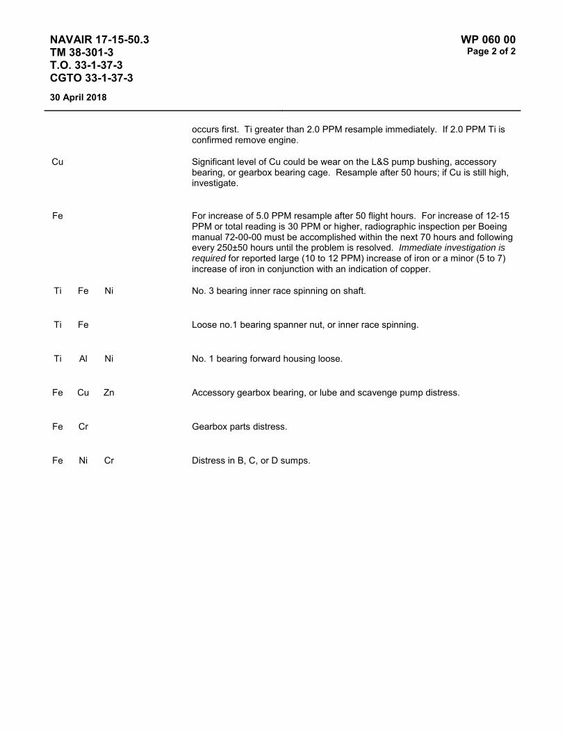
NAVAIR 17-15-50.3 TM 38-301-3 T.O. 33-1-37-3 CGTO 33-1-37-3
WP 060 00 Page 2 of 2
30 April 2018
occurs first. Ti greater than 2.0 PPM resample immediately. If 2.0 PPM Ti is confirmed remove engine.
Cu Significant level of Cu could be wear on the L&S pump bushing, accessory bearing, or gearbox bearing cage. Resample after 50 hours; if Cu is still high, investigate.
Fe For increase of 5.0 PPM resample after 50 flight hours. For increase of 12-15 PPM or total reading is 30 PPM or higher, radiographic inspection per Boeing manual 72-00-00 must be accomplished within the next 70 hours and following every 250±50 hours until the problem is resolved. Immediate investigation is required for reported large (10 to 12 PPM) increase of iron or a minor (5 to 7) increase of iron in conjunction with an indication of copper.
Ti Fe Ni No. 3 bearing inner race spinning on shaft.
Ti Fe Loose no.1 bearing spanner nut, or inner race spinning.
Ti Al Ni No. 1 bearing forward housing loose.
Fe Cu Zn Accessory gearbox bearing, or lube and scavenge pump distress.
Fe Cr Gearbox parts distress.
Fe Ni Cr Distress in B, C, or D sumps.

NAVAIR 17-15-50.3 TM 38-301-3 T.O. 33-1-37-3 CGTO 33-1-37-3
WP 061 00 Page 1 of 2
30 April 2018
TYPE EQUIPMENT Aircraft Engine
MANUFACTURER General Electric
EQUIPMENT/SYSTEM MODEL NUMBER/DESIGNATION
WEAPON SYSTEM PLATFORM(S)
JOAP TYPE EQUIPMENT CODE
F404-GE-F1D2 F-117A N/A
LUBRICATING OIL MIL-PRF-23699 or MIL-PRF-7808 for cold weather ops.
TECHNICAL AUTHORITY Air Force
STATUS Aircraft and engine retire. WP retained for reference.
Table 1 - JOAP ATOMIC EMISSION ROTRODE LIMITS
Fe Ag Al Cr Cu Mg Ni Ti B Si Zn
Abnormal Trend (PPM Increase in 10 Hrs)
3 3 2 2 2 3 3
Normal Range 0-8 0-6 0-3 0-3 0-5 0-6 0-6 Marginal Range 9 7 4 4 6 7 7 High Range 10-11 8-9 5 5 7 8-9 8-9 Abnormal ≥12 ≥10 ≥6 ≥6 ≥8 ≥10 ≥10 10 10 10
Elevated boron (B) and/or zinc (Zn) concentrations usually indicate contamination with another oil type, primarily MIL-PRF-2104. Recommend resampling and retesting immediately. If new value exceeds 8.0 PPM, run check with D19-0 to ensure proper instrument function. When proper function is confirmed, report both results and suspected contamination with MIL-PRF-2104 to chain of command, maintenance chief, cognizant engineering authority (Army and Navy only), and other personnel as specified by local written procedures. Recommend flushing and retesting of contaminated pre-oilers, carts, or other reservoirs where contamination is found until both B and Zn concentrations fall below 8.0 PPM. Refer to JOAP Manual Volume 2, WP 021 00 for more information. Recommend segregation of confirmed or suspected contaminated stocks, and submit information (batch no., lot no., MIL-PRF, nature of problem, etc.) on such stocks through the Defense supply deficiency reporting system.
Elevated silicon (Si) concentration usually indicates contamination with soil, sand, or dust. If aluminum (Al) is also elevated, this suggests the presence of clay or soil. Recommend resampling and retesting immediately. If new value exceeds 8.0 PPM, run check with D19-0 to ensure proper instrument function. When proper function is confirmed, report both results and suspected contamination with soil, sand, or dust to chain of command, maintenance chief, cognizant engineering authority (Army and Navy only), and other personnel as specified by local written procedures. Recommend flushing and retesting of contaminated pre-oilers, carts, or other reservoirs where contamination is found until silicon concentration falls below 8.0 PPM. Refer to JOAP Manual Volume 2, WP 021 00 for more information. Recommend segregation of confirmed or suspected contaminated stocks, and submit information (batch no., lot no., MIL-PRF, nature of problem, etc.) on such stocks through the Defense supply deficiency reporting system.

NAVAIR 17-15-50.3 TM 38-301-3 T.O. 33-1-37-3 CGTO 33-1-37-3
WP 061 00 Page 2 of 2
30 April 2018
NOTES
The requirement for the routine oil analysis on the F404-GE-F1D2 engine installed in the F-117A aircraft has been deleted in accordance with Air Force Message 031600Z Oct 90. Evaluation criteria is being retained for reference and for use as required during special sampling.
The F404-GE-F1D2 engine is not on routine oil analysis. Therefore evaluation of special sampling results may be difficult. If necessary contact cognizant engineering authority for assistance.
Fe & Cr Mo V Main Shaft Bearings
Fe & Ag Main Shaft Cages
Fe & Cr AGB and PTO Bearings
Fe & Ag AGB and PTO Cages
Al Lube and Scavenge Oil Pump
Fe & Ni AGB and PTO, gears, shafts, splines
NOTES
1. High Al (more than 10 PPM) on a newly installed engine generally indicates contamination from the oil tank, oil cooler or lube and scavenge pump.
2. Engine should not be operated if Fe content is 12 PPM or higher.
3. Analysis laboratory will report results of analysis performed to the owning laboratory.
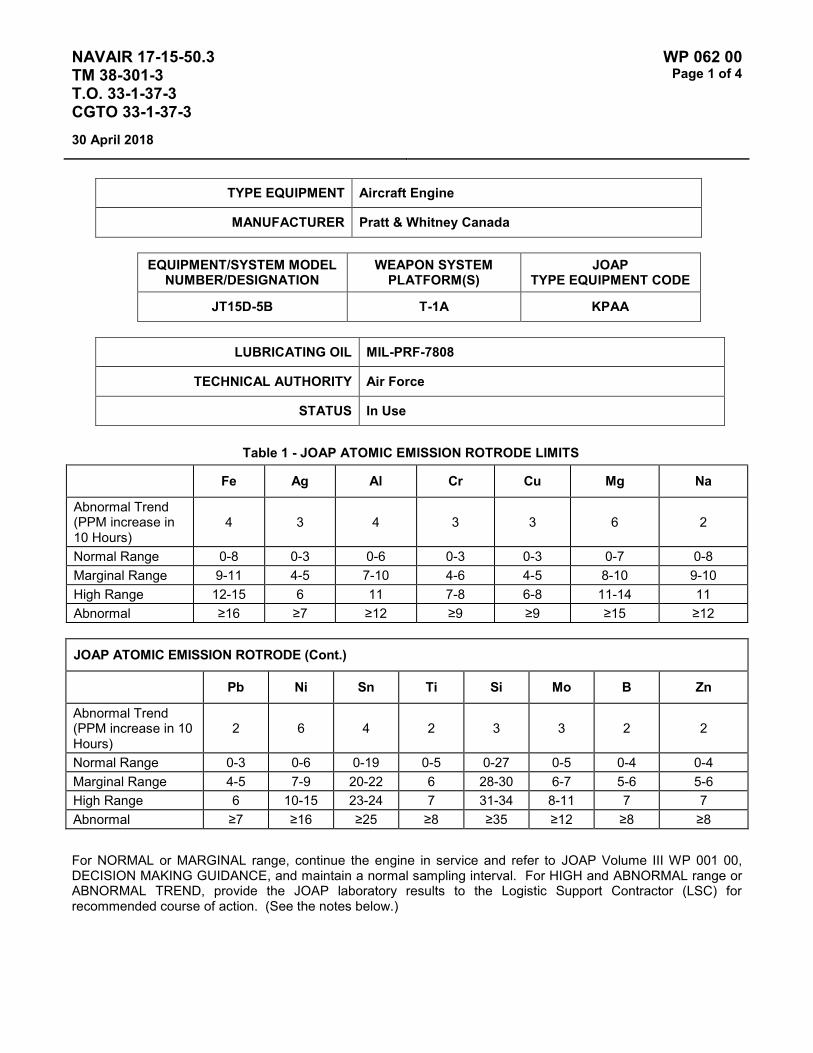
NAVAIR 17-15-50.3 TM 38-301-3 T.O. 33-1-37-3 CGTO 33-1-37-3
WP 062 00 Page 1 of 4
30 April 2018
TYPE EQUIPMENT Aircraft Engine
MANUFACTURER Pratt & Whitney Canada
EQUIPMENT/SYSTEM MODEL NUMBER/DESIGNATION
WEAPON SYSTEM PLATFORM(S)
JOAP TYPE EQUIPMENT CODE
JT15D-5B T-1A KPAA
LUBRICATING OIL MIL-PRF-7808
TECHNICAL AUTHORITY Air Force
STATUS In Use
Table 1 - JOAP ATOMIC EMISSION ROTRODE LIMITS
Fe Ag Al Cr Cu Mg Na
Abnormal Trend (PPM increase in 10 Hours)
4 3 4 3 3 6 2
Normal Range 0-8 0-3 0-6 0-3 0-3 0-7 0-8 Marginal Range 9-11 4-5 7-10 4-6 4-5 8-10 9-10 High Range 12-15 6 11 7-8 6-8 11-14 11 Abnormal ≥16 ≥7 ≥12 ≥9 ≥9 ≥15 ≥12
JOAP ATOMIC EMISSION ROTRODE (Cont.)
Pb Ni Sn Ti Si Mo B Zn
Abnormal Trend (PPM increase in 10 Hours)
2 6 4 2 3 3 2 2
Normal Range 0-3 0-6 0-19 0-5 0-27 0-5 0-4 0-4 Marginal Range 4-5 7-9 20-22 6 28-30 6-7 5-6 5-6 High Range 6 10-15 23-24 7 31-34 8-11 7 7 Abnormal ≥7 ≥16 ≥25 ≥8 ≥35 ≥12 ≥8 ≥8
For NORMAL or MARGINAL range, continue the engine in service and refer to JOAP Volume III WP 001 00, DECISION MAKING GUIDANCE, and maintain a normal sampling interval. For HIGH and ABNORMAL range or ABNORMAL TREND, provide the JOAP laboratory results to the Logistic Support Contractor (LSC) for recommended course of action. (See the notes below.)

NAVAIR 17-15-50.3 TM 38-301-3 T.O. 33-1-37-3 CGTO 33-1-37-3
WP 062 00 Page 2 of 4
30 April 2018
For the HIGH or ABNORMAL range, refer to JOAP Volume 3 WP 001 00, DECISION MAKING GUIDANCE, and proceed as follows: Provide maintenance personnel with the indicated engine components and advise them to check the engine oil filter element for blockage IAW 1T-1A-2-71GS-00-1. If the filter element is serviceable, continue in service. Perform the following steps after the shortest of the following intervals: between one and three hours of operation maximum, since the initial sample or after the next flight
a. Analyze a second engine oil sample. If analysis indicates the presence of elements in the MARGINAL or NORMAL ranges, continue the engine in service and maintain a normal sampling interval.
b. Inspect the engine oil filter element IAW 1T-1A-2-71GS-00-1. Advise the LSC of any contamination found.
c. If analysis of the second oil sample indicates the presence of elements in the HIGH or ABNORMAL ranges, perform the following steps.
(1) Obtain and analyze third and fourth engine oil samples during and after a one-hour engine ground run. Take the third sample after 30 minutes of operation and the fourth after the conclusion of the ground run.
(2) Inspect the engine oil filter element IAW 1T-1A-2-71GS-00-1. If the filter element is serviceable, continue in service.
(3) If analysis of the third and fourth samples indicate the presence of elements in the NORMAL range, continue the engine in service and return to the normal sampling interval.
(4) If analysis of the third and fourth samples indicate the presence of elements in the MARGINAL range, continue the engine in service with special sampling intervals.
(5) If analysis of the third and fourth samples indicate the presence of elements in the HIGH or ABNORMAL ranges, provide the JOAP laboratory results to the LSC for a recommended course of action.
Fe & Mo Cr V Mn Nos. 1, 2, 3, 3½ and 4 bearings and associated races.
Si Co W Ni Cu
Fe & Cr Mn Si Ni Accessory gearbox driveshaft upper and lower tower shaft bearings.
Cu Mo
Ag & Fe Ni Cr Mn Nos. 1, 2, 3, 3½, 4 and tower shaft bearing cages.

NAVAIR 17-15-50.3 TM 38-301-3 T.O. 33-1-37-3 CGTO 33-1-37-3
WP 062 00 Page 3 of 4
30 April 2018
Fe & Ni Cr Mn Cu Accessory gearbox and oil pump gears.
Si Mo
Fe & Cr Mn Si Ni No. 4 bearing air seal (on LPT rotor).
Cu Mo
Al & Sn Cu Ni Accessory gearbox plain bearings, oil check valve housings.
Al & Si Cu Mg Oil pump housing, upper tower shaft bearing housing.
Al & Cu Mg Mn Accessory gearbox scavenge strainer transfer tube.
NOTE
The first two elements are the two most predominant wear elements (in sequence) for each of the components.
INSPECTION RECOMMENDATIONS
If bearing or keywasher material is found in the filter element and is at or above the normal range, provide the JOAP laboratory results to the LSC for a recommended course of action.
If gear material is found, make sure that procedures in 1T-1A-2-71GS-00-1 are completed and advise the laboratory of the results.

NAVAIR 17-15-50.3 TM 38-301-3 T.O. 33-1-37-3 CGTO 33-1-37-3
WP 062 00 Page 4 of 4
30 April 2018
This Page Intentionally Left Blank

NAVAIR 17-15-50.3 TM 38-301-3 T.O. 33-1-37-3 CGTO 33-1-37-3
WP 063 00 Page 1 of 4
30 April 2018
TYPE EQUIPMENT Aircraft Engine
MANUFACTURER Lycoming
EQUIPMENT/SYSTEM MODEL NUMBER/DESIGNATION
WEAPON SYSTEM PLATFORM(S)
JOAP TYPE EQUIPMENT CODE
IO-360-C/D O-2 RBAA
LUBRICATING OIL Lycoming Spec No. 301
TECHNICAL AUTHORITY Air Force
STATUS Aircraft and Engine retired. WP no longer updated but retained for reference purposes.
Table 1 - JOAP ATOMIC EMISSION ROTRODE LIMITS
Fe Ag Al Cr Cu Mg B Si Zn
* Abnormal Trend (PPM Increase in 10 Hrs)
28 3 11 4 8 4
Normal Range 0-91 0-6 0-36 0-13 0-26 0-13 Marginal Range 92-112 7 37-44 14-16 27-32 14-16 High Range 113-139 8-9 45-54 17-19 33-39 17-19 Abnormal ≥140 ≥10 ≥55 ≥20 ≥40 ≥20 10 10 10 NOTE: * If the calculated PPM trend value is equal to or greater than the trend PPM value limit, the engine has an
abnormal trend.
Increases in Fe and Cr are indicative ring/cylinder wear. Increase in Cu by itself, or in combination with Fe, indicates rod and main bearing discrepancy.
Elevated boron (B) and/or zinc (Zn) concentrations usually indicate contamination with another oil type, primarily MIL-PRF-2104. Recommend resampling and retesting immediately. If new value exceeds 8.0 PPM, run check with D19-0 to ensure proper instrument function. When proper function is confirmed, report both results and suspected contamination with MIL-PRF-2104 to chain of command, maintenance chief, cognizant engineering authority (Army and Navy only), and other personnel as specified by local written procedures. Recommend flushing and retesting of contaminated pre-oilers, carts, or other reservoirs where contamination is found until both B and Zn concentrations fall below 8.0 PPM. Refer to JOAP Manual Volume 2, WP 021 00 for more information. Recommend segregation of confirmed or suspected contaminated stocks, and submit information (batch no., lot no., MIL-PRF, nature of problem, etc.) on such stocks through the Defense supply deficiency reporting system.
Elevated silicon (Si) concentration usually indicates contamination with soil, sand, or dust. If aluminum (Al) is also elevated, this suggests the presence of clay or soil. Recommend resampling and retesting immediately. If new

NAVAIR 17-15-50.3 TM 38-301-3 T.O. 33-1-37-3 CGTO 33-1-37-3
WP 063 00 Page 2 of 4
30 April 2018
value exceeds 8.0 PPM, run check with D19-0 to ensure proper instrument function. When proper function is confirmed, report both results and suspected contamination with soil, sand, or dust to chain of command, maintenance chief, cognizant engineering authority (Army and Navy only), and other personnel as specified by local written procedures. Recommend flushing and retesting of contaminated pre-oilers, carts, or other reservoirs where contamination is found until silicon concentration falls below 8.0 PPM. Refer to JOAP Manual Volume 2, WP 021 00 for more information. Recommend segregation of confirmed or suspected contaminated stocks, and submit information (batch no., lot no., MIL-PRF, nature of problem, etc.) on such stocks through the Defense supply deficiency reporting system.
NOTE
O-series engines are "wet sump" (oil pan) type engines and oil tank capacity is small. This causes tendency for sample contamination. Frequent oil change interval (50 hours) must be considered when evaluating JOAP results. An orange colored band at the cylinder base indicates chrome plated barrels. Engines thus equipped should be expected to produce high chrome wear metal during break-in period (up to 150 hours), but should decrease and stabilize thereafter. Laboratory personnel should inquire whether engines producing high chrome wear metals are equipped with chrome plated cylinders, and base maintenance recommendations upon this knowledge
Fe Push rods, camshaft, cylinder barrels, rocker arms, crankshaft, valve lifters, valve springs, washers
Fe Ni + Cr Oil pump gears, crankshaft cluster gear, governor drive gears, camshaft gears, piston rings
Cu Pb + Sn Valve rocker bushings, accessory drive bushings, main bearings, connecting rod bearings
Cu Sn + Zn Valve guides, piston pin bushings
Fe Cr Ni Valves
Si + W
Al Cu Ni + Mg Pistons, crankcase, cylinder head
Mg Cu + Al Crankcase rear cover
OIL CAPACITY AND CONSUMPTION INFORMATION
1. Oil capacity of the engine is 9 quarts. Minimum 6 quarts required for flight.
2. Allowable oil consumption rates (quantity per time):

NAVAIR 17-15-50.3 TM 38-301-3 T.O. 33-1-37-3 CGTO 33-1-37-3
WP 063 00 Page 3 of 4
30 April 2018
a. At full throttle: 2¾ pints per hour maximum (T.O. 1L-2A-1).
b. Normal: not to exceed 1½ pints per hour.
c. Recommended oil consumption inspection interval (if appropriate for your engine): Overhaul determinant; i.e. 900 accumulated hours since last overhaul.
d. Actions to take if maximum allowable oil consumption rate is exceeded: Overhaul engine.

NAVAIR 17-15-50.3 TM 38-301-3 T.O. 33-1-37-3 CGTO 33-1-37-3
WP 063 00 Page 4 of 4
30 April 2018
This Page Intentionally Left Blank
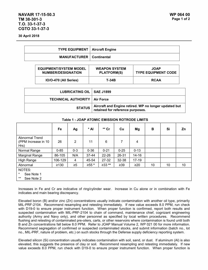
NAVAIR 17-15-50.3 TM 38-301-3 T.O. 33-1-37-3 CGTO 33-1-37-3
WP 064 00 Page 1 of 2
30 April 2018
TYPE EQUIPMENT Aircraft Engine
MANUFACTURER Continental
EQUIPMENT/SYSTEM MODEL NUMBER/DESIGNATION
WEAPON SYSTEM PLATFORM(S)
JOAP TYPE EQUIPMENT CODE
IO/O-470 (All Series) T-34B RCAA
LUBRICATING OIL SAE J1899
TECHNICAL AUTHORITY Air Force
STATUS Aircraft and Engine retired. WP no longer updated but retained for reference purposes.
Table 1 - JOAP ATOMIC EMISSION ROTRODE LIMITS
Fe Ag * Al ** Cr Cu Mg B Si Zn
Abnormal Trend (PPM Increase in 10 Hrs)
26 2 11 6 7 4
Normal Range 0-85 0-3 0-36 0-21 0-25 0-13 Marginal Range 86-105 N/A 37-44 22-26 26-31 14-16 High Range 106-129 4 45-54 27-32 32-38 17-19 Abnormal ≥130 ≥5 ≥55 * ≥33 ** ≥39 ≥20 10 10 10 NOTES: * See Note 1 ** See Note 2
Increases in Fe and Cr are indicative of ring/cylinder wear. Increase in Cu alone or in combination with Fe indicates and main bearing discrepancy.
Elevated boron (B) and/or zinc (Zn) concentrations usually indicate contamination with another oil type, primarily MIL-PRF-2104. Recommend resampling and retesting immediately. If new value exceeds 8.0 PPM, run check with D19-0 to ensure proper instrument function. When proper function is confirmed, report both results and suspected contamination with MIL-PRF-2104 to chain of command, maintenance chief, cognizant engineering authority (Army and Navy only), and other personnel as specified by local written procedures. Recommend flushing and retesting of contaminated pre-oilers, carts, or other reservoirs where contamination is found until both B and Zn concentrations fall below 8.0 PPM. Refer to JOAP Manual Volume 2, WP 021 00 for more information. Recommend segregation of confirmed or suspected contaminated stocks, and submit information (batch no., lot no., MIL-PRF, nature of problem, etc.) on such stocks through the Defense supply deficiency reporting system.
Elevated silicon (Si) concentration usually indicates contamination with soil, sand, or dust. If aluminum (Al) is also elevated, this suggests the presence of clay or soil. Recommend resampling and retesting immediately. If new value exceeds 8.0 PPM, run check with D19-0 to ensure proper instrument function. When proper function is
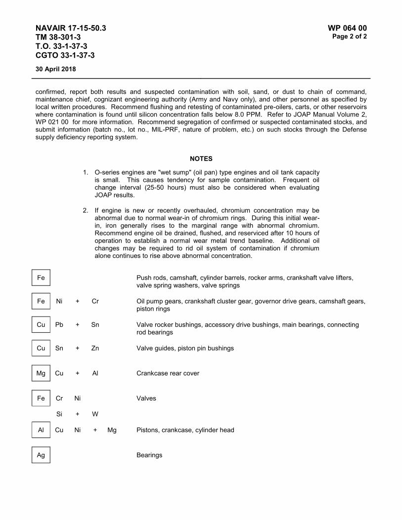
NAVAIR 17-15-50.3 TM 38-301-3 T.O. 33-1-37-3 CGTO 33-1-37-3
WP 064 00 Page 2 of 2
30 April 2018
confirmed, report both results and suspected contamination with soil, sand, or dust to chain of command, maintenance chief, cognizant engineering authority (Army and Navy only), and other personnel as specified by local written procedures. Recommend flushing and retesting of contaminated pre-oilers, carts, or other reservoirs where contamination is found until silicon concentration falls below 8.0 PPM. Refer to JOAP Manual Volume 2, WP 021 00 for more information. Recommend segregation of confirmed or suspected contaminated stocks, and submit information (batch no., lot no., MIL-PRF, nature of problem, etc.) on such stocks through the Defense supply deficiency reporting system.
NOTES
1. O-series engines are "wet sump" (oil pan) type engines and oil tank capacity is small. This causes tendency for sample contamination. Frequent oil change interval (25-50 hours) must also be considered when evaluating JOAP results.
2. If engine is new or recently overhauled, chromium concentration may be abnormal due to normal wear-in of chromium rings. During this initial wear-in, iron generally rises to the marginal range with abnormal chromium. Recommend engine oil be drained, flushed, and reserviced after 10 hours of operation to establish a normal wear metal trend baseline. Additional oil changes may be required to rid oil system of contamination if chromium alone continues to rise above abnormal concentration.
Fe Push rods, camshaft, cylinder barrels, rocker arms, crankshaft valve lifters, valve spring washers, valve springs
Fe Ni + Cr Oil pump gears, crankshaft cluster gear, governor drive gears, camshaft gears, piston rings
Cu Pb + Sn Valve rocker bushings, accessory drive bushings, main bearings, connecting rod bearings
Cu Sn + Zn Valve guides, piston pin bushings
Mg Cu + Al Crankcase rear cover
Fe Cr Ni Valves
Si + W
Al Cu Ni + Mg Pistons, crankcase, cylinder head
Ag Bearings

NAVAIR 17-15-50.3 TM 38-301-3 T.O. 33-1-37-3 CGTO 33-1-37-3
WP 065 00 Page 1 of 2
30 April 2018
TYPE EQUIPMENT Aircraft Engine
MANUFACTURER Continental
EQUIPMENT/SYSTEM MODEL NUMBER/DESIGNATION
WEAPON SYSTEM PLATFORM(S)
JOAP TYPE EQUIPMENT CODE
O-470-4 T-34B RCAA
LUBRICATING OIL SAE J1899
TECHNICAL AUTHORITY NAVAIR
STATUS Aircraft and Engine retired. WP no longer updated but retained for reference purposes.
Table 1 - JOAP ATOMIC EMISSION ROTRODE LIMITS
Fe Ag * Al Cr Cu Mg B Si Zn
Abnormal Trend (PPM Increase in 10 Hrs)
13 12 23 * 9
Normal Range 0-64 0-40 0-76 * 0-30
Marginal Range 65-78 41-50 77-96 * 31-36
High Range 79-91 51-59 97-115 * 37-46
Abnormal ≥92 ≥60 ≥116 * ≥47 10 10 10
NOTE: * For newly reworked engine with other metal normal (up to 150-200 operating hours after overhaul).
Increases in Fe and Al are indicative of upper cylinder problems. Increase in Cu or in combination with Fe indicates rod and main bearing wear.
Elevated boron (B) and/or zinc (Zn) concentrations usually indicate contamination with another oil type, primarily MIL-PRF-2104. Recommend resampling and retesting immediately. If new value exceeds 8.0 PPM, run check with D19-0 to ensure proper instrument function. When proper function is confirmed, report both results and suspected contamination with MIL-PRF-2104 to chain of command, maintenance chief, cognizant engineering authority (Army and Navy only), and other personnel as specified by local written procedures. Recommend flushing and retesting of contaminated pre-oilers, carts, or other reservoirs where contamination is found until both B and Zn concentrations fall below 8.0 PPM. Refer to JOAP Manual Volume 2, WP 021 00 for more information. Recommend segregation of confirmed or suspected contaminated stocks, and submit information (batch no., lot

NAVAIR 17-15-50.3 TM 38-301-3 T.O. 33-1-37-3 CGTO 33-1-37-3
WP 065 00 Page 2 of 2
30 April 2018
no., MIL-PRF, nature of problem, etc.) on such stocks through the Defense supply deficiency reporting system.
Elevated silicon (Si) concentration usually indicates contamination with soil, sand, or dust. If aluminum (Al) is also elevated, this suggests the presence of clay or soil. Recommend resampling and retesting immediately. If new value exceeds 8.0 PPM, run check with D19-0 to ensure proper instrument function. When proper function is confirmed, report both results and suspected contamination with soil, sand, or dust to chain of command, maintenance chief, cognizant engineering authority (Army and Navy only), and other personnel as specified by local written procedures. Recommend flushing and retesting of contaminated pre-oilers, carts, or other reservoirs where contamination is found until silicon concentration falls below 8.0 PPM. Refer to JOAP Manual Volume 2, WP 021 00 for more information. Recommend segregation of confirmed or suspected contaminated stocks, and submit information (batch no., lot no., MIL-PRF, nature of problem, etc.) on such stocks through the Defense supply deficiency reporting system.
Fe Push rods, camshaft, cylinder barrels, rocker arms, crankshaft valve lifters, valve spring washers, valve springs
Fe Ni + Cr Oil pump gears, crankshaft cluster gear, governor drive gears, camshaft gears, piston rings
Cu Pb + Sn Valve rocker bushings, accessory drive bushings, main bearings, connecting rod bearings
Cu Sn + Zn Valve guides, piston pin bushings
Fe Cr Ni Valves
Si + W
Al Cu Ni + Mg Pistons, crankcase, cylinder head
Mg Cu + Al Crankcase rear cover

NAVAIR 17-15-50.3 TM 38-301-3 T.O. 33-1-37-3 CGTO 33-1-37-3
WP 066 00 Page 1 of 2
30 April 2018
TYPE EQUIPMENT Aircraft Engine
MANUFACTURER Lycoming
EQUIPMENT/SYSTEM MODEL NUMBER/DESIGNATION
WEAPON SYSTEM PLATFORM(S)
JOAP TYPE EQUIPMENT CODE
O-480 U-4 N/A
LUBRICATING OIL SAE J1899
TECHNICAL AUTHORITY Army
STATUS Aircraft and Engine retired. WP no longer updated but retained for reference purposes.
Table 1 - JOAP ATOMIC EMISSION ROTRODE LIMITS
Fe Ag Al Cr Cu Mg B Si Zn
Abnormal Trend (PPM Increase in 10 Hrs)
21 2 9 20 10 4
Normal Range 0-72 0-3 0-30 0-65 0-33 0-14 Marginal Range 73-88 N/A 31-37 66-80 34-40 15-17 High Range 89-109 4 38-44 81-99 41-49 18-21 Abnormal ≥110 ≥5 ≥45 ≥100 ≥50 ≥22 10 10 10
High Al and/or Fe may indicate trouble in rocker boxes. Valve springs may be cutting into retainers, or thrust washers on rocker shaft may be wearing into side of rocker box.
Elevated boron (B) and/or zinc (Zn) concentrations usually indicate contamination with another oil type, primarily MIL-PRF-2104. Recommend resampling and retesting immediately. If new value exceeds 8.0 PPM, run check with D19-0 to ensure proper instrument function. When proper function is confirmed, report both results and suspected contamination with MIL-PRF-2104 to chain of command, maintenance chief, cognizant engineering authority (Army and Navy only), and other personnel as specified by local written procedures. Recommend flushing and retesting of contaminated pre-oilers, carts, or other reservoirs where contamination is found until both B and Zn concentrations fall below 8.0 PPM. Refer to JOAP Manual Volume 2, WP 021 00 for more information. Recommend segregation of confirmed or suspected contaminated stocks, and submit information (batch no., lot no., MIL-PRF, nature of problem, etc.) on such stocks through the Defense supply deficiency reporting system.
Elevated silicon (Si) concentration usually indicates contamination with soil, sand, or dust. If aluminum (Al) is also elevated, this suggests the presence of clay or soil. Recommend resampling and retesting immediately. If new value exceeds 8.0 PPM, run check with D19-0 to ensure proper instrument function. When proper function is confirmed, report both results and suspected contamination with soil, sand, or dust to chain of command, maintenance chief, cognizant engineering authority (Army and Navy only), and other personnel as specified by local written procedures. Recommend flushing and retesting of contaminated pre-oilers, carts, or other reservoirs

NAVAIR 17-15-50.3 TM 38-301-3 T.O. 33-1-37-3 CGTO 33-1-37-3
WP 066 00 Page 2 of 2
30 April 2018
where contamination is found until silicon concentration falls below 8.0 PPM. Refer to JOAP Manual Volume 2, WP 021 00 for more information. Recommend segregation of confirmed or suspected contaminated stocks, and submit information (batch no., lot no., MIL-PRF, nature of problem, etc.) on such stocks through the Defense supply deficiency reporting system.
Fe Cu Bearing wear
Fe Cr Al Rings, Piston, Cylinder wear
NOTES
O-series engines are "wet sump" (oil pan) type engines and oil tank capacity is small. This causes tendency for sample contamination. Frequent oil change interval (25-50 hours) must also be considered when evaluating JOAP results.

NAVAIR 17-15-50.3 TM 38-301-3 T.O. 33-1-37-3 CGTO 33-1-37-3
WP 067 00 Page 1 of 2
30 April 2018
TYPE EQUIPMENT HUNTER Heavy Fuel Engine (HFE)
MANUFACTURER Northrop Grumman
EQUIPMENT/SYSTEM MODEL NUMBER/DESIGNATION
WEAPON SYSTEM PLATFORM(S)
JOAP TYPE EQUIPMENT CODE
Hunter HFE Engine MQ-5B RJAA
LUBRICATING OIL Mobil 0W40
TECHNICAL AUTHORITY Army Aviation Command
STATUS In Use
INTERPRETATION AND CORRECTIVE ACTION GUIDE
TABLE 1. Corrective Action Codes OK No action required. Oil sample is within acceptable tolerances. C Change oil and oil filter E Replace engine. Send removed engine to depot for evaluation.
Analysis Parameter
Viscosity Kv100Cst
TBN D4739 *
TBN D2896
TAN D664
Oxidation/ Nitration (FT-IR)
Normal Range 11–18 OK >4 OK >6 OK <1 OK <1 OK Borderline Range ** 18–20 OK 2–4 OK 4–6 OK 1–3 OK 10–25 OK
Warning Range <10 or >20 C <2 C <4 C >3 C >25 C NOTES: * If new TBN is known, the warning range is a reduction greater than 50%. ** Ok for continued use. The next oil sample, however, will likely fall in the warning range requiring an oil and
filter change.

NAVAIR 17-15-50.3 TM 38-301-3 T.O. 33-1-37-3 CGTO 33-1-37-3
WP 067 00 Page 2 of 2
30 April 2018
Recommended Oil Analysis Wear Metal Limits ***
Wear Metal (PPM)
Aluminum (Al)
Chromium (Cr)
Copper (Cu)
Iron (Fe)
Lead (Pb)
Nickel (Ni)
Tin (Sn)
Normal <10 OK <5 OK <10 OK <100 OK <20 OK <5 OK <10 OK
Borderline Range 9-19 C 4–14 C 1 –25 C 101–199 C 21–49 C 6–10 C 11-25 C
Warning >20 E >15 E >25 E >200 E >50 E >10 E >25 E
Recommended Oil Analysis Contamination Limits ***
Analysis Parameter
Dirt (Silicon,
PPM) %Soot
(Weight)
Coolant (PPM) %Water
(Volume) %Fuel
(Volume) Potassium (K)
Sodium (Na) Glycol
Normal <25 OK <3 OK <20 OK <40 OK <20 OK <0.25 OK <2 OK Borderline >25 C >3 C >20 OK >40 C >20 C >0.25 C >2 C Warning >50 C *** >6 C *** >50 E >100 E >50 E >0.5 E >5 E
NOTE: *** Some parameters are interactive. The presence of any combination of the below requires engine removal
and return to the depot for evaluation: 1. Fe in the borderline range AND Cr in the borderline range AND Silicon. 2. Pb in the borderline range AND Sn in the borderline range. 3. Fe in the borderline range AND soot.

NAVAIR 17-15-50.3 TM 38-301-3 T.O. 33-1-37-3 CGTO 33-1-37-3
WP 068 00 Page 1 of 2
30 April 2018
TYPE EQUIPMENT MAIN TRANSMISSION (NAVY / USMC AH-1W, UH-1N)
MANUFACTURER Bell Helicopter Textron, Inc.
EQUIPMENT/SYSTEM MODEL NUMBER/DESIGNATION
WEAPON SYSTEM PLATFORM(S)
JOAP TYPE EQUIPMENT CODE
MainXmsn AH-1W AHAX1
MainXmsn UH-1N GAMN
LUBRICATING OIL DOD-PRF-85734 (Alternative oil: MIL-PRF-23699 or MIL-PRF-7808)
TECHNICAL AUTHORITY NAVAIRSYSCOM
STATUS In Use
Wear metal analysis is not required. Frequent oil changes and 3 micron filtration disrupt the normal oil analysis trending to the point where it is not a consistent indicator of gearbox condition.
Table 1 – WATER CONTENT VIA AQUATEST * LIMITS Normal ≤ 1200
Abnormal >1200 ** * For Aquatest Method see Volume 2 Work Packages 009 or 010 depending on instrument being used
Water content analysis is required in accordance with Organizational Level Maintenance Instructions. Primary concern for water content analysis is proper adherence to NAVAIR 15-01-500 manual to maintain gearboxes during periods of inactivity. Water content entering into preservation, during preservation (if type I or type II preservation is utilized), and when depreserving gearboxes is 1200 ppm with no action required. If aircraft can be operated, water content may be as high as 1500 ppm, but aircraft must be operated sufficiently to reduce water content below 1200 ppm. If aircraft cannot be operated when water content is between 1200 ppm and 1500 ppm or if water content exceeds 1500 ppm, gearbox shall be drained and flushed as necessary to correct high water content.

NAVAIR 17-15-50.3 TM 38-301-3 T.O. 33-1-37-3 CGTO 33-1-37-3
WP 068 00 Page 2 of 2
30 April 2018
This Page Intentionally Left Blank
NAVAIR 17-15-50.3 TM 38-301-3 T.O. 33-1-37-3 CGTO 33-1-37-3
WP 069 00 Page 1 of 2
30 April 2018
TYPE EQUIPMENT 42 DEGREE (INTERMEDIATE) GEARBOX (NAVY / USMC AH-1W, UH-1N)
MANUFACTURER Bell Helicopter Textron, Inc.
EQUIPMENT/SYSTEM MODEL NUMBER/DESIGNATION
WEAPON SYSTEM PLATFORM(S)
JOAP TYPE EQUIPMENT CODE
42/Int Gbx AH-1W AHAX2
42/Int Gbx UH-1N GAIN
LUBRICATING OIL DOD-PRF-85734 (Alternative oil: MIL-PRF-23699 or MIL-PRF-7808)
TECHNICAL AUTHORITY NAVAIRSYSCOM
STATUS In Use
Wear metal analysis is not required. Frequent oil changes disrupt the normal oil analysis trending to the point where it is not a consistent indicator of gearbox condition.
Table 1 – WATER CONTENT VIA AQUATEST * LIMITS Normal ≤ 1200
Abnormal >1200 ** * For Aquatest Method see Volume 2 Work Packages 009 or 010 depending on instrument being used
Water content analysis is required in accordance with Organizational Level Maintenance Instructions. Primary concern for water content analysis is proper adherence to NAVAIR 15-01-500 manual to maintain gearboxes during periods of inactivity. Water content entering into preservation, during preservation (if type I or type II preservation is utilized), and when depreserving gearboxes is 1200 ppm with no action required. If aircraft can be operated, water content may be as high as 1500 ppm, but aircraft must be operated sufficiently to reduce water content below 1200 ppm. If aircraft cannot be operated when water content is between 1200 ppm and 1500 ppm or if water content exceeds 1500 ppm, gearbox shall be drained and flushed as necessary to correct high water content.

NAVAIR 17-15-50.3 TM 38-301-3 T.O. 33-1-37-3 CGTO 33-1-37-3
WP 069 00 Page 2 of 2
30 April 2018
This Page Intentionally Left Blank

NAVAIR 17-15-50.3 TM 38-301-3 T.O. 33-1-37-3 CGTO 33-1-37-3
WP 070 00 Page 1 of 2
30 April 2018
TYPE EQUIPMENT 90 DEGREE (TAIL ROTOR) GEARBOX (NAVY / USMC AH-1W, UH-1N)
MANUFACTURER Bell Helicopter Textron, Inc.
EQUIPMENT/SYSTEM MODEL NUMBER/DESIGNATION
WEAPON SYSTEM PLATFORM(S)
JOAP TYPE EQUIPMENT CODE
90/Tail Gbx AH-1W AHAX3
90/Tail Gbx UH-1N GATN
LUBRICATING OIL DOD-PRF-85734 (Alternative oil: MIL-PRF-23699 or MIL-PRF-7808)
TECHNICAL AUTHORITY NAVAIRSYSCOM
STATUS In Use
Wear metal analysis is not required. Frequent oil changes disrupt the normal oil analysis trending to the point where it is not a consistent indicator of gearbox condition.
Table 1 – WATER CONTENT VIA AQUATEST * LIMITS Normal ≤ 1200
Abnormal >1200 ** * For Aquatest Method see Volume 2 Work Packages 009 or 010 depending on instrument being used
Water content analysis is required in accordance with Organizational Level Maintenance Instructions. Primary concern for water content analysis is proper adherence to NAVAIR 15-01-500 manual to maintain gearboxes during periods of inactivity. Water content entering into preservation, during preservation (if type I or type II preservation is utilized), and when depreserving gearboxes is 1200 ppm with no action required. If aircraft can be operated, water content may be as high as 1500 ppm, but aircraft must be operated sufficiently to reduce water content below 1200 ppm. If aircraft cannot be operated when water content is between 1200 ppm and 1500 ppm or if water content exceeds 1500 ppm, gearbox shall be drained and flushed as necessary to correct high water content.

NAVAIR 17-15-50.3 TM 38-301-3 T.O. 33-1-37-3 CGTO 33-1-37-3
WP 070 00 Page 2 of 2
30 April 2018
This Page Intentionally Left Blank

NAVAIR 17-15-50.3 TM 38-301-3 T.O. 33-1-37-3 CGTO 33-1-37-3
WP 071 00 Page 1 of 2
30 April 2018
TYPE EQUIPMENT COMBINING GEARBOX (NAVY / USMC AH-1W, UH-1Y, AH-1Z)
MANUFACTURER Bell Helicopter Textron, Inc.
EQUIPMENT/SYSTEM MODEL NUMBER/DESIGNATION
WEAPON SYSTEM PLATFORM(S)
JOAP TYPE EQUIPMENT CODE
Eng Comb Gbx AH-1W AHAX4
Eng Comb Gbx UH-1Y AHAA4
Eng Comb Gbx AH-1Z AHAB4
LUBRICATING OIL DOD-PRF-85734 (Alternative oil: MIL-PRF-23699 or MIL-PRF-7808)
TECHNICAL AUTHORITY NAVAIRSYSCOM
STATUS In Use
Wear metal analysis is not required. Frequent oil changes and 3 micron filtration disrupt the normal oil analysis trending to the point where it is not a consistent indicator of gearbox condition.
Table 1 – WATER CONTENT VIA AQUATEST * LIMITS Normal ≤ 1200
Abnormal >1200 ** * For Aquatest Method see Volume 2 Work Packages 009 or 010 depending on instrument being used
Water content analysis is required in accordance with Organizational Level Maintenance Instructions. Primary concern for water content analysis is proper adherence to NAVAIR 15-01-500 manual to maintain gearboxes during periods of inactivity. Water content entering into preservation, during preservation (if type I or type II preservation is utilized), and when depreserving gearboxes is 1200 ppm with no action required. If aircraft can be operated, water content may be as high as 1500 ppm, but aircraft must be operated sufficiently to reduce water content below 1200 ppm. If aircraft cannot be operated when water content is between 1200 ppm and 1500 ppm or if water content exceeds 1500 ppm, gearbox shall be drained and flushed as necessary to correct high water content.

NAVAIR 17-15-50.3 TM 38-301-3 T.O. 33-1-37-3 CGTO 33-1-37-3
WP 071 00 Page 2 of 2
30 April 2018
This Page Intentionally Left Blank

NAVAIR 17-15-50.3 TM 38-301-3 T.O. 33-1-37-3 CGTO 33-1-37-3
WP 072 00 Page 1 of 2
30 April 2018
TYPE EQUIPMENT MAIN ROTOR GEARBOX (TRANSMISSION) (NAVY / USMC UH-1Y, AH-1Z)
MANUFACTURER Bell Helicopter Textron, Inc.
EQUIPMENT/SYSTEM MODEL NUMBER/DESIGNATION
WEAPON SYSTEM PLATFORM(S)
JOAP TYPE EQUIPMENT CODE
Main Xmsn UH-1Y AHAA1
Main Xmsn AH-1Z AHAB1
LUBRICATING OIL DOD-PRF-85734 (Alternative oil: MIL-PRF-23699 or MIL-PRF-7808)
TECHNICAL AUTHORITY NAVAIRSYSCOM
STATUS In Use
Wear metal analysis is not required. Frequent oil changes and 3 micron filtration disrupt the normal oil analysis trending to the point where it is not a consistent indicator of gearbox condition.
Table 1 – WATER CONTENT VIA AQUATEST * LIMITS Normal ≤ 1200
Abnormal >1200 ** * For Aquatest Method see Volume 2 Work Packages 009 or 010 depending on instrument being used
Water content analysis is required in accordance with Organizational Level Maintenance Instructions. Primary concern for water content analysis is proper adherence to NAVAIR 15-01-500 manual to maintain gearboxes during periods of inactivity. Water content entering into preservation, during preservation (if type I or type II preservation is utilized), and when depreserving gearboxes is 1200 ppm with no action required. If aircraft can be operated, water content may be as high as 1500 ppm, but aircraft must be operated sufficiently to reduce water content below 1200 ppm. If aircraft cannot be operated when water content is between 1200 ppm and 1500 ppm or if water content exceeds 1500 ppm, gearbox shall be drained and purged as necessary to correct high water content.
Additional water content analysis is required due to main rotor mast seal design issues. Water content analysis is also required in accordance with Special/Conditional/Preservation Maintenance Requirement Cards. Water content limits are 1200 ppm with no action required. If aircraft can be operated, water content may be as high as 1500 ppm, but aircraft must be operated sufficiently to reduce water content below 1200 ppm. If aircraft cannot be operated when water content is between 1200 ppm and 1500 ppm or if water content exceeds 1500 ppm, gearbox shall be drained and purged as necessary to correct high water content.

NAVAIR 17-15-50.3 TM 38-301-3 T.O. 33-1-37-3 CGTO 33-1-37-3
WP 072 00 Page 2 of 2
30 April 2018
This Page Intentionally Left Blank

NAVAIR 17-15-50.3 TM 38-301-3 T.O. 33-1-37-3 CGTO 33-1-37-3
WP 073 00 Page 1 of 2
30 April 2018
TYPE EQUIPMENT INTERMEDIATE GEARBOX (NAVY / USMC UH-1Y, AH-1Z)
MANUFACTURER Bell Helicopter Textron, Inc.
EQUIPMENT/SYSTEM MODEL NUMBER/DESIGNATION
WEAPON SYSTEM PLATFORM(S)
JOAP TYPE EQUIPMENT CODE
42/Int Gbx UH-1Y AHAA2
42/Int Gbx AH-1Z AHAB2
LUBRICATING OIL DOD-PRF-85734 (Alternative oil: MIL-PRF-23699 or MIL-PRF-7808)
TECHNICAL AUTHORITY NAVAIRSYSCOM
STATUS In Use
Wear metal analysis is not required. Frequent oil changes disrupt the normal oil analysis trending to the point where it is not a consistent indicator of gearbox condition.
Table 1 – WATER CONTENT VIA AQUATEST * LIMITS Normal ≤ 1200
Abnormal >1200 ** * For Aquatest Method see Volume 2 Work Packages 009 or 010 depending on instrument being used
Water content analysis is required in accordance with Organizational Level Maintenance Instructions. Primary concern for water content analysis is proper adherence to NAVAIR 15-01-500 manual to maintain gearboxes during periods of inactivity. Water content entering into preservation, during preservation (if type I or type II preservation is utilized), and when depreserving gearboxes is 1200 ppm with no action required. If aircraft can be operated, water content may be as high as 1500 ppm, but aircraft must be operated sufficiently to reduce water content below 1200 ppm. If aircraft cannot be operated when water content is between 1200 ppm and 1500 ppm or if water content exceeds 1500 ppm, gearbox shall be drained and flushed as necessary to correct high water content.
NAVAIR 17-15-50.3 TM 38-301-3 T.O. 33-1-37-3 CGTO 33-1-37-3
WP 073 00 Page 2 of 2
30 April 2018
This Page Intentionally Left Blank
NAVAIR 17-15-50.3 TM 38-301-3 T.O. 33-1-37-3 CGTO 33-1-37-3
WP 074 00 Page 1 of 2
30 April 2018
TYPE EQUIPMENT TAIL ROTOR GEARBOX (NAVY / USMC UH-1Y, AH-1Z)
MANUFACTURER Bell Helicopter Textron, Inc.
EQUIPMENT/SYSTEM MODEL NUMBER/DESIGNATION
WEAPON SYSTEM PLATFORM(S)
JOAP TYPE EQUIPMENT CODE
90/Tail Gbx UH-1Y AHAA3
90/Tail Gbx AH-1Z AHAB3
LUBRICATING OIL DOD-PRF-85734 (Alternative oil: MIL-PRF-23699 or MIL-PRF-7808)
TECHNICAL AUTHORITY NAVAIRSYSCOM
STATUS In Use
Wear metal analysis is not required. Frequent oil changes disrupt the normal oil analysis trending to the point where it is not a consistent indicator of gearbox condition.
Table 1 – WATER CONTENT VIA AQUATEST * LIMITS Normal ≤ 1200
Abnormal >1200 ** * For Aquatest Method see Volume 2 Work Packages 009 or 010 depending on instrument being used
Water content analysis is required in accordance with Organizational Level Maintenance Instructions. Primary concern for water content analysis is proper adherence to NAVAIR 15-01-500 manual to maintain gearboxes during periods of inactivity. Water content entering into preservation, during preservation (if type I or type II preservation is utilized), and when depreserving gearboxes is 1200 ppm with no action required. If aircraft can be operated, water content may be as high as 1500 ppm, but aircraft must be operated sufficiently to reduce water content below 1200 ppm. If aircraft cannot be operated when water content is between 1200 ppm and 1500 ppm or if water content exceeds 1500 ppm, gearbox shall be drained and flushed as necessary to correct high water content.

NAVAIR 17-15-50.3 TM 38-301-3 T.O. 33-1-37-3 CGTO 33-1-37-3
WP 074 00 Page 2 of 2
30 April 2018
This Page Intentionally Left Blank

NAVAIR 17-15-50.3 TM 38-301-3 T.O. 33-1-37-3 CGTO 33-1-37-3
WP 075 00 Page 1 of 2
30 April 2018
TYPE EQUIPMENT T400 COMBINING GEARBOX
MANUFACTURER Pratt and Whitney Canada
EQUIPMENT/SYSTEM MODEL NUMBER/DESIGNATION
WEAPON SYSTEM PLATFORM(S)
JOAP TYPE EQUIPMENT CODE
Eng Comb Gbx UH-1N GAEN
LUBRICATING OIL DOD-PRF-85734
TECHNICAL AUTHORITY AIR FORCE
STATUS In Use
Table 1 - JOAP ATOMIC EMISSION ROTRODE LIMITS
Fe Ag Al Cr Cu Mg B Si Zn
Abnormal Trend (PPM Increase in 10 Hrs)
5 2 3 5
Normal Range 0-16 0-6 0-10 0-17 0-10 Marginal Range 17-19 7 11-12 18-21 High Range 20-24 8-9 13-14 22-25 Abnormal ≥25 10+ ≥15 ≥26 10 >10 10
Table 2 – WATER CONTENT VIA AQUATEST * LIMITS Normal ≤ 1000
Abnormal >1000 ** * For Aquatest Method see Volume 2 Work Packages 009 or 010 depending on instrument being used

NAVAIR 17-15-50.3 TM 38-301-3 T.O. 33-1-37-3 CGTO 33-1-37-3
WP 075 00 Page 2 of 2
30 April 2018
Elevated boron (B) and/or zinc (Zn) concentrations usually indicate contamination with another oil type, primarily MIL-PRF-2104. Recommend resampling and retesting immediately. If new value exceeds 8.0 PPM, run check with D19-0 to ensure proper instrument function. When proper function is confirmed, report both results and suspected contamination with MIL-PRF-2104 to chain of command, maintenance chief, cognizant engineering authority (Army and Navy only), and other personnel as specified by local written procedures. Recommend flushing and retesting of contaminated pre-oilers, carts, or other reservoirs where contamination is found until both B and Zn concentrations fall below 8.0 PPM. Refer to JOAP Manual Volume 2, WP 021 00 for more information. Recommend segregation of confirmed or suspected contaminated stocks, and submit information (batch no., lot no., MIL-PRF, nature of problem, etc.) on such stocks through the Defense supply deficiency reporting system.
Elevated silicon (Si) concentration usually indicates contamination with soil, sand, or dust. If aluminum (Al) is also elevated, this suggests the presence of clay or soil. Recommend resampling and retesting immediately. If new value exceeds 8.0 PPM, run check with D19-0 to ensure proper instrument function. When proper function is confirmed, report both results and suspected contamination with soil, sand, or dust to chain of command, maintenance chief, cognizant engineering authority (Army and Navy only), and other personnel as specified by local written procedures. Recommend flushing and retesting of contaminated pre-oilers, carts, or other reservoirs where contamination is found until silicon concentration falls below 8.0 PPM. Refer to JOAP Manual Volume 2, WP 021 00 for more information. Recommend segregation of confirmed or suspected contaminated stocks, and submit information (batch no., lot no., MIL-PRF, nature of problem, etc.) on such stocks through the Defense supply deficiency reporting system.

NAVAIR 17-15-50.3 TM 38-301-3 T.O. 33-1-37-3 CGTO 33-1-37-3
WP 076 00 Page 1 of 2
30 April 2018
TYPE EQUIPMENT MAIN TRANSMISSION H-1 (ALL SERIES) (ARMY AND AIR FORCE)
MANUFACTURER Bell Helicopter
EQUIPMENT/SYSTEM MODEL NUMBER/DESIGNATION
WEAPON SYSTEM PLATFORM(S)
JOAP TYPE EQUIPMENT CODE
Main Xmsn UH-1N (Air Force) GAMN
Main Xmsn UH-1H (Army) GAMH
Main Xmsn UH-1V (Army) GAMV
Main Xmsn UH-1X (Army) GAMX
LUBRICATING OIL DOD-PRF-85734 (Alternative oil: MIL-PRF-23699 or MIL-PRF-7808)
TECHNICAL AUTHORITY Army Aviation Command
STATUS In Use
Table 1 - JOAP ATOMIC EMISSION ROTRODE LIMITS
Fe Ag Al Cr Cu Mg B Si Zn
Abnormal Trend (PPM Increase in 10 Hrs)
6 2 7 2 4 3 7
Normal Range 0-21 0-3 0-25 0-3 0-13 0-8 0-23 Marginal Range 22-26 N/A 26-31 4 14-16 9 24-28 High Range 27-31 4 32-38 5 17-19 10-11 29-34 Abnormal ≥32 ≥5 ≥39 ≥6 ≥20 ≥12 10 ≥35 10
Fe Bearing load surface, main drive, Accessory gearing and splines
Fe & Cu Bearing assemblies Mast and input quill bearing assembly
Fe Cu & Ag Input and output quill bearing assemblies
Fe & Al Lower mast bearing oil distribution ring

NAVAIR 17-15-50.3 TM 38-301-3 T.O. 33-1-37-3 CGTO 33-1-37-3
WP 076 00 Page 2 of 2
30 April 2018
Fe & Mg Gearing and housing
Al Oil deflector plate input quill
Elevated boron (B) and/or zinc (Zn) concentrations usually indicate contamination with another oil type, primarily MIL-PRF-2104. Recommend resampling and retesting immediately. If new value exceeds 8.0 PPM, run check with D19-0 to ensure proper instrument function. When proper function is confirmed, report both results and suspected contamination with MIL-PRF-2104 to chain of command, maintenance chief, cognizant engineering authority (Army and Navy only), and other personnel as specified by local written procedures. Recommend flushing and retesting of contaminated pre-oilers, carts, or other reservoirs where contamination is found until both B and Zn concentrations fall below 8.0 PPM. Refer to JOAP Manual Volume 2, WP 021 00 for more information. Recommend segregation of confirmed or suspected contaminated stocks, and submit information (batch no., lot no., MIL-PRF, nature of problem, etc.) on such stocks through the Defense supply deficiency reporting system.
NOTES
High concentration of Fe & Mg should be expected to increase after extended periods of inactivity because of corrosion.
Mast bearing shims manufactured from Al are being replaced with steel counterpart at overhaul.
High Si indicates contamination probably due to sampling error.

NAVAIR 17-15-50.3 TM 38-301-3 T.O. 33-1-37-3 CGTO 33-1-37-3
WP 077 00 Page 1 of 2
30 April 2018
TYPE EQUIPMENT 42° INTERMEDIATE GEARBOX H-1 (ALL SERIES) (ARMY AND AIR FORCE)
MANUFACTURER Bell Helicopter
EQUIPMENT/SYSTEM MODEL NUMBER/DESIGNATION
WEAPON SYSTEM PLATFORM(S)
JOAP TYPE EQUIPMENT CODE
42/Int Gbx UH-1N (Air Force) GAIN
42/Int Gbx UH-1H (Army) GAIH
42/Int Gbx UH-1V (Army) GAIV
42/Int Gbx UH-1X (Army) GAIX
LUBRICATING OIL DOD-PRF-85734 (Alternative oil: MIL-PRF-23699 or MIL-PRF-7808)
TECHNICAL AUTHORITY Army Aviation Command
STATUS In Use
Table 1 - JOAP ATOMIC EMISSION ROTRODE LIMITS
Fe Ag Al Cr Cu Mg B Si Zn
Abnormal Trend (PPM Increase in 10 Hrs)
12 4 2 7 10 15
Normal Range 0-40 0-14 0-5 0-24 0-33 0-48 Marginal Range 41-49 15-17 6 25-29 34-40 49-59 High Range 50-61 18-21 7 30-36 41-49 60-74 Abnormal ≥62 ≥22 ≥8 ≥37 ≥50 10 ≥75 10
Fe Bevel gears and bearing load surfaces
Fe & Cu Bevel gears and bearing assembly
Fe Cu & Al Bearing assembly and liners
Fe & Al Bearing liners in quill plate
Fe Al & Mg Gearing and case

NAVAIR 17-15-50.3 TM 38-301-3 T.O. 33-1-37-3 CGTO 33-1-37-3
WP 077 00 Page 2 of 2
30 April 2018
Elevated boron (B) and/or zinc (Zn) concentrations usually indicate contamination with another oil type, primarily MIL-PRF-2104. Recommend resampling and retesting immediately. If new value exceeds 8.0 PPM, run check with D19-0 to ensure proper instrument function. When proper function is confirmed, report both results and suspected contamination with MIL-PRF-2104 to chain of command, maintenance chief, cognizant engineering authority (Army and Navy only), and other personnel as specified by local written procedures. Recommend flushing and retesting of contaminated pre-oilers, carts, or other reservoirs where contamination is found until both B and Zn concentrations fall below 8.0 PPM. Refer to JOAP Manual Volume 2, WP 021 00 for more information. Recommend segregation of confirmed or suspected contaminated stocks, and submit information (batch no., lot no., MIL-PRF, nature of problem, etc.) on such stocks through the Defense supply deficiency reporting system.
NOTES
1. Tail rotor or drive line vibration may induce temporary high concentration of Fe, Cu & Al.
2. Fe, Cu & Mg should be expected to increase sharply after extended periods of inactivity because of corrosion.
3. Ag has been reported to occur in some gearboxes at very high levels. Silver in these cases was used as a gear flashing to establish wear patterns for gear tracking and should not be considered as a critical wear metal.

NAVAIR 17-15-50.3 TM 38-301-3 T.O. 33-1-37-3 CGTO 33-1-37-3
WP 078 00 Page 1 of 2
30 April 2018
TYPE EQUIPMENT 90° TAIL ROTOR GEARBOX H-1 (ALL SERIES) (ARMY AND AIR FORCE)
MANUFACTURER Bell Helicopter
EQUIPMENT/SYSTEM MODEL NUMBER/DESIGNATION
WEAPON SYSTEM PLATFORM(S)
JOAP TYPE EQUIPMENT CODE
90/Tail Gbx UH-1N (Air Force) GATN
90/Tail Gbx UH-1H (Army) GATH
90/Tail Gbx UH-1V (Army) GATV
90/Tail Gbx UH-1X (Army) GATX
LUBRICATING OIL DOD-PRF-85734 (Alternative oil: MIL-PRF-23699 or MIL-PRF-7808)
TECHNICAL AUTHORITY Army Aviation Command
STATUS In Use
Table 1 - JOAP ATOMIC EMISSION ROTRODE LIMITS
Fe Ag Al Cr Cu Mg B Si Zn
Abnormal Trend (PPM Increase in 10 Hrs)
26 10 4 26 15 20
Normal Range 0-85 0-35 0-10 0-85 0-48 0-65 Marginal Range 86-105 36-43 11-12 86-105 49-59 66-80 High Range 106-129 44-52 13-15 106-129 60-74 81-99 Abnormal ≥130 ≥53 ≥16 ≥130 ≥75 10 ≥100 10
Fe Bevel gears and bearing load surfaces
Fe Cu & Al Bearing assembly and liners
Fe & Al Bearing liners in quill plate
Fe Al & Mg Gearing and case

NAVAIR 17-15-50.3 TM 38-301-3 T.O. 33-1-37-3 CGTO 33-1-37-3
WP 078 00 Page 2 of 2
30 April 2018
Elevated boron (B) and/or zinc (Zn) concentrations usually indicate contamination with another oil type, primarily MIL-PRF-2104. Recommend resampling and retesting immediately. If new value exceeds 8.0 PPM, run check with D19-0 to ensure proper instrument function. When proper function is confirmed, report both results and suspected contamination with MIL-PRF-2104 to chain of command, maintenance chief, cognizant engineering authority (Army and Navy only), and other personnel as specified by local written procedures. Recommend flushing and retesting of contaminated pre-oilers, carts, or other reservoirs where contamination is found until both B and Zn concentrations fall below 8.0 PPM. Refer to JOAP Manual Volume 2, WP 021 00 for more information. Recommend segregation of confirmed or suspected contaminated stocks, and submit information (batch no., lot no., MIL-PRF, nature of problem, etc.) on such stocks through the Defense supply deficiency reporting system.
NOTES
1. Temporary high concentration of Fe, Cu, and Al may result from tail rotor or drive line vibration.
2. The concentration of Fe, Al & Mg should be expected to increase sharply after extended periods of inactivity because of corrosion.
3. High concentration of Fe, Cu & Mg may result from excessive lubrication of tail rotor cross head bearing forcing grease and external debris into contact with gearbox oil. Flushing overcomes the problem but requires a 10 minute ground operation following each drain and reservice.
4. Inspect the aluminum wool in the filter cap for deterioration when excessive aluminum wear metal is detected in oil samples.

NAVAIR 17-15-50.3 TM 38-301-3 T.O. 33-1-37-3 CGTO 33-1-37-3
WP 079 00 Page 1 of 2
30 April 2018
TYPE EQUIPMENT MAIN GEARBOX SH-2G (NAVY)
MANUFACTURER Kaman Helicopter
EQUIPMENT/SYSTEM MODEL NUMBER/DESIGNATION
WEAPON SYSTEM PLATFORM(S)
JOAP TYPE EQUIPMENT CODE
Main Xmsn H-2 GBMA
Main Xmsn SH-2G GBMG
LUBRICATING OIL DOD-PRF-85734 (Alternative oil: MIL-PRF-23699 or MIL-PRF-7808)
TECHNICAL AUTHORITY NAVAIR
STATUS Aircraft Retired. WP Maintained for Reference.
Table 1 - JOAP ATOMIC EMISSION ROTRODE LIMITS
Fe Ag Al Cr Cu Mg Ni Ti B Si Zn
Abnormal Trend (PPM Increase in 10 Hrs)
17 4 6 10 6 6
Normal Range 0-60 0-12 0-20 0-18 0-18 0-18 Marginal Range 61-70 13-15 21-25 19-22 19-22 19-22 High Range 71-86 16-17 26-30 23-26 23-26 23-26 Abnormal ≥87 ≥18 ≥31 ≥27 ≥27 ≥27 10 10 10
Table 2 – WATER CONTENT VIA AQUATEST * LIMITS Normal ≤ 1000
Abnormal >1000 * For Aquatest Method see Volume 2 Work Packages 009 or 010 depending on instrument being used
The main gearbox shares a common oil system with the combining gearbox with oil filters both in the oil pump and in the scavenge oil return line. Normal wear particles will continue to increase until the gearbox is drained, flushed, and reserviced in accordance with NAVAIR 01-260HCD-2-4.1. Water in the oil will cause high iron and magnesium because of corrosion. When high or abnormal wear metals are detected and/or the water content of the oil exceeds 1,000 PPM (0.100 percent)*, the laboratory recommendation should be "flush gearbox, reservice and perform serviceability check in accordance with NAVAIR 01-260HCD-2-4.1. Submit oil sample after

NAVAIR 17-15-50.3 TM 38-301-3 T.O. 33-1-37-3 CGTO 33-1-37-3
WP 079 00 Page 2 of 2
30 April 2018
serviceability check and special oil sample after 10 flight hours of operation for both wear metals and water content."
*Water content check dependent on special equipment availability.
High metal readings without exceeding 100 PPM water content may result in a laboratory recommendation for flushing or removal of the gearbox. A minimum of two consecutive high readings is required prior to recommending flushing or gearbox removal unless secondary indications (chips, unusual noise, etc.) are present. Inform CFA when recommending flushing. CFA concurrence is required prior to recommending gearbox removal. Furnish CFA with five previous NOAP readings when recommending gearbox removal. CFA is NOAP readings when recommending gearbox removal.
Elevated boron (B) and/or zinc (Zn) concentrations usually indicate contamination with another oil type, primarily MIL-PRF-2104. Recommend resampling and retesting immediately. If new value exceeds 8.0 PPM, run check with D19-0 to ensure proper instrument function. When proper function is confirmed, report both results and suspected contamination with MIL-PRF-2104 to chain of command, maintenance chief, cognizant engineering authority (Army and Navy only), and other personnel as specified by local written procedures. Recommend flushing and retesting of contaminated pre-oilers, carts, or other reservoirs where contamination is found until both B and Zn concentrations fall below 8.0 PPM. Refer to JOAP Manual Volume 2, WP 021 00 for more information. Recommend segregation of confirmed or suspected contaminated stocks, and submit information (batch no., lot no., MIL-PRF, nature of problem, etc.) on such stocks through the Defense supply deficiency reporting system.
Elevated silicon (Si) concentration usually indicates contamination with soil, sand, or dust. If aluminum (Al) is also elevated, this suggests the presence of clay or soil. Recommend resampling and retesting immediately. If new value exceeds 8.0 PPM, run check with D19-0 to ensure proper instrument function. When proper function is confirmed, report both results and suspected contamination with soil, sand, or dust to chain of command, maintenance chief, cognizant engineering authority (Army and Navy only), and other personnel as specified by local written procedures. Recommend flushing and retesting of contaminated pre-oilers, carts, or other reservoirs where contamination is found until silicon concentration falls below 8.0 PPM. Refer to JOAP Manual Volume 2, WP 021 00 for more information. Recommend segregation of confirmed or suspected contaminated stocks, and submit information (batch no., lot no., MIL-PRF, nature of problem, etc.) on such stocks through the Defense supply deficiency reporting system.

NAVAIR 17-15-50.3 TM 38-301-3 T.O. 33-1-37-3 CGTO 33-1-37-3
WP 080 00 Page 1 of 2
30 April 2018
TYPE EQUIPMENT INTERMEDIATE GEARBOX SH-2G (NAVY)
MANUFACTURER Kaman Helicopter
EQUIPMENT/SYSTEM MODEL NUMBER/DESIGNATION
WEAPON SYSTEM PLATFORM(S)
JOAP TYPE EQUIPMENT CODE
42/Int Gbx H-2 GBIA
42/Int Gbx SH-2G GBIG
LUBRICATING OIL DOD-PRF-85734 (Alternative oil: MIL-PRF-23699 or MIL-PRF-7808)
TECHNICAL AUTHORITY NAVAIR
STATUS Aircraft Retired. WP Maintained for Reference.
Table 1 - JOAP ATOMIC EMISSION ROTRODE LIMITS
Fe Ag Al Cr Cu Mg B Si Zn
Abnormal Trend (PPM Increase in 10 Hrs)
16 8 6 10
Normal Range 0-54 0-25 0-20 0-26 Marginal Range 55-64 26-31 21-25 27-32 High Range 65-80 32-37 26-30 33-39 Abnormal ≥81 ≥38 ≥31 ≥40 10 10 10
Table 2 – WATER CONTENT VIA AQUATEST * LIMITS Normal ≤ 1000
Abnormal >1000 ** * For Aquatest Method see Volume 2 Work Packages 009 or 010 depending on instrument being used
The intermediate gearbox has a self-contained oil system without an oil filter. Normal wear particles will continue to increase until the gearbox is drained, flushed and re-serviced in accordance with NAVAIR 01-260HCD-2-4.1. Water in the oil will cause high iron and magnesium because of corrosion. When high or abnormal wear metal readings are obtained, check the oil for water content. If high or abnormal wear metals are detected and/or the water content of the oil exceeds 1,000 PPM (0.100 percent)*, the laboratory recommendation should be "flush gearbox, re-service and perform serviceability check in accordance with NAVAIR 01-260HCD-2-4.1. Submit oil
NAVAIR 17-15-50.3 TM 38-301-3 T.O. 33-1-37-3 CGTO 33-1-37-3
WP 080 00 Page 2 of 2
30 April 2018
sample after serviceability check and special oil sample after 10 flight hours of operation for both wear metals and water content."
*Water content check dependent on special equipment availability.
High metal readings without exceeding 100 PPM water content may result in a laboratory recommendation for flushing or removal of the gearbox. A minimum of two consecutive high readings is required prior to recommending flushing or gearbox removal. Furnish CFA with five previous NOAP readings when recommending gearbox removal.
Elevated boron (B) and/or zinc (Zn) concentrations usually indicate contamination with another oil type, primarily MIL-PRF-2104. Recommend resampling and retesting immediately. If new value exceeds 8.0 PPM, run check with D19-0 to ensure proper instrument function. When proper function is confirmed, report both results and suspected contamination with MIL-PRF-2104 to chain of command, maintenance chief, cognizant engineering authority (Army and Navy only), and other personnel as specified by local written procedures. Recommend flushing and retesting of contaminated pre-oilers, carts, or other reservoirs where contamination is found until both B and Zn concentrations fall below 8.0 PPM. Refer to JOAP Manual Volume 2, WP 021 00 for more information. Recommend segregation of confirmed or suspected contaminated stocks, and submit information (batch no., lot no., MIL-PRF, nature of problem, etc.) on such stocks through the Defense supply deficiency reporting system.
Elevated silicon (Si) concentration usually indicates contamination with soil, sand, or dust. If aluminum (Al) is also elevated, this suggests the presence of clay or soil. Recommend resampling and retesting immediately. If new value exceeds 8.0 PPM, run check with D19-0 to ensure proper instrument function. When proper function is confirmed, report both results and suspected contamination with soil, sand, or dust to chain of command, maintenance chief, cognizant engineering authority (Army and Navy only), and other personnel as specified by local written procedures. Recommend flushing and retesting of contaminated pre-oilers, carts, or other reservoirs where contamination is found until silicon concentration falls below 8.0 PPM. Refer to JOAP Manual Volume 2, WP 021 00 for more information. Recommend segregation of confirmed or suspected contaminated stocks, and submit information (batch no., lot no., MIL-PRF, nature of problem, etc.) on such stocks through the Defense supply deficiency reporting system.

NAVAIR 17-15-50.3 TM 38-301-3 T.O. 33-1-37-3 CGTO 33-1-37-3
WP 081 00 Page 1 of 2
30 April 2018
TYPE EQUIPMENT TAIL ROTOR GEARBOX SH-2G (NAVY)
MANUFACTURER Kaman Helicopter
EQUIPMENT/SYSTEM MODEL NUMBER/DESIGNATION
WEAPON SYSTEM PLATFORM(S)
JOAP TYPE EQUIPMENT CODE
90/Tail Gbx H-2 GBTA
90/Tail Gbx SH-2G GBTG
LUBRICATING OIL DOD-PRF-85734 (Alternative oil: MIL-PRF-23699 or MIL-PRF-7808)
TECHNICAL AUTHORITY NAVAIR
STATUS Aircraft Retired. WP Maintained for Reference.
Table 1 - JOAP ATOMIC EMISSION ROTRODE LIMITS
Fe Ag Al Cr Cu Mg B Si Zn
Abnormal Trend (PPM Increase in 10 Hrs)
17 4 6 10
Normal Range 0-60 0-12 0-20 0-18 Marginal Range 61-70 13-15 21-25 19-22 High Range 71-86 16-17 26-30 23-26 Abnormal ≥87 ≥18 ≥31 ≥27 10 10 10
Table 2 – WATER CONTENT VIA AQUATEST * LIMITS Normal ≤ 1000
Abnormal >1000 * For Aquatest Method see Volume 2 Work Packages 009 or 010 depending on instrument being used
The tail rotor gearbox has a self-contained gearbox without an oil filter. Normal wear particles will continue to increase until the gearbox is drained, flushed and re-serviced in accordance with NAVAIR 01-260HCD-2-4.1. Water in the oil will cause either high iron and copper or high iron, copper, magnesium and aluminum because of corrosion. When high or abnormal wear metal readings are obtained, check the oil for water content. If high or abnormal wear metals are detected and/or the water content of the oil exceeds 1,000 (0.100 percent)*, the laboratory recommendation should be "flush gearbox, re-service and perform serviceability check in accordance with NAVAIR 01-260HCD-2-4.1. Submit oil sample after serviceability check and special oil sample after 10 flight

NAVAIR 17-15-50.3 TM 38-301-3 T.O. 33-1-37-3 CGTO 33-1-37-3
WP 081 00 Page 2 of 2
30 April 2018
hours of operation for both wear metals and water content."
*Water content check dependent on special equipment availability.
High metal readings without exceeding 1000 PPM water content may result in a laboratory recommendation for flushing or removal of the gearbox. A minimum of two consecutive high readings is required prior to recommending flushing or gearbox removal unless secondary indications (chips, unusual noise, etc.) are present. Inform CFA when recommending flushing. CFA concurrence is required prior to recommending gearbox removal. Furnish CFA with five previous NOAP readings when recommending gearbox removal.
Elevated boron (B) and/or zinc (Zn) concentrations usually indicate contamination with another oil type, primarily MIL-PRF-2104. Recommend resampling and retesting immediately. If new value exceeds 8.0 PPM, run check with D19-0 to ensure proper instrument function. When proper function is confirmed, report both results and suspected contamination with MIL-PRF-2104 to chain of command, maintenance chief, cognizant engineering authority (Army and Navy only), and other personnel as specified by local written procedures. Recommend flushing and retesting of contaminated pre-oilers, carts, or other reservoirs where contamination is found until both B and Zn concentrations fall below 8.0 PPM. Refer to JOAP Manual Volume 2, WP 021 00 for more information. Recommend segregation of confirmed or suspected contaminated stocks, and submit information (batch no., lot no., MIL-PRF, nature of problem, etc.) on such stocks through the Defense supply deficiency reporting system.
Elevated silicon (Si) concentration usually indicates contamination with soil, sand, or dust. If aluminum (Al) is also elevated, this suggests the presence of clay or soil. Recommend resampling and retesting immediately. If new value exceeds 8.0 PPM, run check with D19-0 to ensure proper instrument function. When proper function is confirmed, report both results and suspected contamination with soil, sand, or dust to chain of command, maintenance chief, cognizant engineering authority (Army and Navy only), and other personnel as specified by local written procedures. Recommend flushing and retesting of contaminated pre-oilers, carts, or other reservoirs where contamination is found until silicon concentration falls below 8.0 PPM. Refer to JOAP Manual Volume 2, WP 021 00 for more information. Recommend segregation of confirmed or suspected contaminated stocks, and submit information (batch no., lot no., MIL-PRF, nature of problem, etc.) on such stocks through the Defense supply deficiency reporting system.

NAVAIR 17-15-50.3 TM 38-301-3 T.O. 33-1-37-3 CGTO 33-1-37-3
WP 082 00 Page 1 of 2
30 April 2018
TYPE EQUIPMENT COMBINING GEARBOX SH-2G (NAVY)
MANUFACTURER Kaman Helicopter
EQUIPMENT/SYSTEM MODEL NUMBER/DESIGNATION
WEAPON SYSTEM PLATFORM(S)
JOAP TYPE EQUIPMENT CODE
#1 Nose Gbx SH-2G GB1G
#2 Nose Gbx SH-2G GB2G
LUBRICATING OIL DOD-PRF-85734 (Alternative oil: MIL-PRF-23699 or MIL-PRF-7808)
TECHNICAL AUTHORITY NAVAIR
STATUS Aircraft Retired. WP Maintained for Reference.
Table 1 - JOAP ATOMIC EMISSION ROTRODE LIMITS
Fe Ag Al Cr Cu Mg Ni B Si Zn
Abnormal Trend (PPM Increase in 10 Hrs)
17 4 6 10 6
Normal Range 0-60 0-12 0-20 0-18 0-18 Marginal Range 61-70 13-15 21-25 19-22 19-22 High Range 71-86 16-17 26-30 23-26 23-26 Abnormal ≥87 ≥18 ≥31 ≥27 ≥27 10 10 10
Table 2 – WATER CONTENT VIA AQUATEST * LIMITS Normal ≤ 1000
Abnormal >1000 * For Aquatest Method see Volume 2 Work Packages 009 or 010 depending on instrument being used
The combining gearbox shares a common oil system with the main gearbox with oil filters both in the oil pump and in the scavenge oil return line. Normal wear particles will continue to increase until the gearbox is drained, flushed and re-serviced in accordance with NAVAIR 01-260HCD-2-4.1. Water in the oil will cause high iron and magnesium because of corrosion. When high or abnormal wear metal readings are obtained, check the oil for water content. If high or abnormal wear metals are detected and/or the water content of the oil exceeds 1,000 (0.100 percent)*, the laboratory recommendation should be "flush gearbox, re-service and perform serviceability

NAVAIR 17-15-50.3 TM 38-301-3 T.O. 33-1-37-3 CGTO 33-1-37-3
WP 082 00 Page 2 of 2
30 April 2018
check in accordance with NAVAIR 01-260HCD-2-4.1. Submit oil sample after serviceability check and special oil sample after 10 flight hours of operation for both wear metals and water content."
*Water content check dependent on special equipment availability.
High metal readings without exceeding 1000 PPM water content may result in a laboratory recommendation for flushing or removal of the gearbox. A minimum of two consecutive high readings is required prior to recommending flushing or gearbox removal unless secondary indications (chips, unusual noise, etc.) are present. Inform CFA when recommending flushing. CFA concurrence is required prior to recommending gearbox removal. Furnish CFA with five previous NOAP readings when recommending gearbox removal.
Elevated boron (B) and/or zinc (Zn) concentrations usually indicate contamination with another oil type, primarily MIL-PRF-2104. Recommend resampling and retesting immediately. If new value exceeds 8.0 PPM, run check with D19-0 to ensure proper instrument function. When proper function is confirmed, report both results and suspected contamination with MIL-PRF-2104 to chain of command, maintenance chief, cognizant engineering authority (Army and Navy only), and other personnel as specified by local written procedures. Recommend flushing and retesting of contaminated pre-oilers, carts, or other reservoirs where contamination is found until both B and Zn concentrations fall below 8.0 PPM. Refer to JOAP Manual Volume 2, WP 021 00 for more information. Recommend segregation of confirmed or suspected contaminated stocks, and submit information (batch no., lot no., MIL-PRF, nature of problem, etc.) on such stocks through the Defense supply deficiency reporting system.
Elevated silicon (Si) concentration usually indicates contamination with soil, sand, or dust. If aluminum (Al) is also elevated, this suggests the presence of clay or soil. Recommend resampling and retesting immediately. If new value exceeds 8.0 PPM, run check with D19-0 to ensure proper instrument function. When proper function is confirmed, report both results and suspected contamination with soil, sand, or dust to chain of command, maintenance chief, cognizant engineering authority (Army and Navy only), and other personnel as specified by local written procedures. Recommend flushing and retesting of contaminated pre-oilers, carts, or other reservoirs where contamination is found until silicon concentration falls below 8.0 PPM. Refer to JOAP Manual Volume 2, WP 021 00 for more information. Recommend segregation of confirmed or suspected contaminated stocks, and submit information (batch no., lot no., MIL-PRF, nature of problem, etc.) on such stocks through the Defense supply deficiency reporting system.

NAVAIR 17-15-50.3 TM 38-301-3 T.O. 33-1-37-3 CGTO 33-1-37-3
WP 083 00 Page 1 of 2
30 April 2018
TYPE EQUIPMENT MAIN TRANSMISSION H-3 (NAVY)
MANUFACTURER Sikorsky
EQUIPMENT/SYSTEM MODEL NUMBER/DESIGNATION
WEAPON SYSTEM PLATFORM(S)
JOAP TYPE EQUIPMENT CODE
Main Xmsn H-3 Unassigned
LUBRICATING OIL DOD-PRF-85734 (Alternative oil: MIL-PRF-23699 or MIL-PRF-7808)
TECHNICAL AUTHORITY NAVAIRSYSCOM
STATUS Aircraft retired. WP retained for reference.
Table 1 - JOAP ATOMIC EMISSION ROTRODE LIMITS
Fe Ag Al Cr Cu Mg B Si Zn
Abnormal Trend (PPM Increase in 10 Hrs)
10 2 4 2 5 4
Normal Range 0-33 0-4 0-10 0-5 0-16 0-13 Marginal Range 34-40 5 11-12 6 17-20 14-16 High Range 41-49 6 13-14 7 21-24 17-19 Abnormal ≥50 ≥7 ≥15 ≥8 ≥25 ≥20 10 10 10
Table 2 – WATER CONTENT VIA AQUATEST * LIMITS Normal ≤ 1000
Abnormal >1000 * For Aquatest Method see Volume 2 Work Packages 009 or 010 depending on instrument being used
Fe alone usually indicates discrepancy in spider gear reduction area. Cu wear metals associated with oil pump bushing accessory drive wheel or main mast bushing bearing.
Water in the oil could cause high iron, copper, magnesium or aluminum due to corrosion. If high or abnormal wear metals are obtained and high water is detected on two consecutive samples, the laboratory recommendation may be to flush Main Transmission, reservice and perform serviceability check. Info CFA when recommending flushing.
Elevated boron (B) and/or zinc (Zn) concentrations usually indicate contamination with another oil type, primarily

NAVAIR 17-15-50.3 TM 38-301-3 T.O. 33-1-37-3 CGTO 33-1-37-3
WP 083 00 Page 2 of 2
30 April 2018
MIL-PRF-2104. Recommend resampling and retesting immediately. If new value exceeds 8.0 PPM, run check with D19-0 to ensure proper instrument function. When proper function is confirmed, report both results and suspected contamination with MIL-PRF-2104 to chain of command, maintenance chief, cognizant engineering authority (Army and Navy only), and other personnel as specified by local written procedures. Recommend flushing and retesting of contaminated pre-oilers, carts, or other reservoirs where contamination is found until both B and Zn concentrations fall below 8.0 PPM. Refer to JOAP Manual Volume 2, WP 021 00 for more information. Recommend segregation of confirmed or suspected contaminated stocks, and submit information (batch no., lot no., MIL-PRF, nature of problem, etc.) on such stocks through the Defense supply deficiency reporting system.
Elevated silicon (Si) concentration usually indicates contamination with soil, sand, or dust. If aluminum (Al) is also elevated, this suggests the presence of clay or soil. Recommend resampling and retesting immediately. If new value exceeds 8.0 PPM, run check with D19-0 to ensure proper instrument function. When proper function is confirmed, report both results and suspected contamination with soil, sand, or dust to chain of command, maintenance chief, cognizant engineering authority (Army and Navy only), and other personnel as specified by local written procedures. Recommend flushing and retesting of contaminated pre-oilers, carts, or other reservoirs where contamination is found until silicon concentration falls below 8.0 PPM. Refer to JOAP Manual Volume 2, WP 021 00 for more information. Recommend segregation of confirmed or suspected contaminated stocks, and submit information (batch no., lot no., MIL-PRF, nature of problem, etc.) on such stocks through the Defense supply deficiency reporting system.

NAVAIR 17-15-50.3 TM 38-301-3 T.O. 33-1-37-3 CGTO 33-1-37-3
WP 084 00 Page 1 of 2
30 April 2018
TYPE EQUIPMENT 42° INTERMEDIATE GEARBOX H-3 (NAVY)
MANUFACTURER Sikorsky
EQUIPMENT/SYSTEM MODEL NUMBER/DESIGNATION
WEAPON SYSTEM PLATFORM(S)
JOAP TYPE EQUIPMENT CODE
42/Int Gbx H-3 GCIA
LUBRICATING OIL DOD-PRF-85734 (Alternative oil: MIL-PRF-23699 or MIL-PRF-7808)
TECHNICAL AUTHORITY NAVAIRSYSCOM
STATUS Aircraft retired. WP retained for reference.
Table 1 - JOAP ATOMIC EMISSION ROTRODE LIMITS
Fe Ag Al Cr Cu Mg B Si Zn
Abnormal Trend (PPM Increase in 10 Hrs)
13 3 8 8
Normal Range 0-43 0-10 0-27 0-27 Marginal Range 44-53 11-12 28-33 28-33 High Range 54-63 13-15 34-40 34-40 Abnormal ≥64 ≥16 ≥41 ≥41 10 10 10
Table 2 – WATER CONTENT VIA AQUATEST * LIMITS Normal ≤ 1000
Abnormal >1000 * For Aquatest Method see Volume 2 Work Packages 009 or 010 depending on instrument being used
Water in the oil could cause high iron, copper, magnesium or aluminum due to corrosion. If high or abnormal wear metals are obtained and high water is detected on two consecutive samples, the laboratory recommendation may be to flush gearbox, re-service and perform serviceability check. Info CFA when recommending flushing.
Elevated boron (B) and/or zinc (Zn) concentrations usually indicate contamination with another oil type, primarily MIL-PRF-2104. Recommend resampling and retesting immediately. If new value exceeds 8.0 PPM, run check with D19-0 to ensure proper instrument function. When proper function is confirmed, report both results and suspected contamination with MIL-PRF-2104 to chain of command, maintenance chief, cognizant engineering

NAVAIR 17-15-50.3 TM 38-301-3 T.O. 33-1-37-3 CGTO 33-1-37-3
WP 084 00 Page 2 of 2
30 April 2018
authority (Army and Navy only), and other personnel as specified by local written procedures. Recommend flushing and retesting of contaminated pre-oilers, carts, or other reservoirs where contamination is found until both B and Zn concentrations fall below 8.0 PPM. Refer to JOAP Manual Volume 2, WP 021 00 for more information. Recommend segregation of confirmed or suspected contaminated stocks, and submit information (batch no., lot no., MIL-PRF, nature of problem, etc.) on such stocks through the Defense supply deficiency reporting system.
Elevated silicon (Si) concentration usually indicates contamination with soil, sand, or dust. If aluminum (Al) is also elevated, this suggests the presence of clay or soil. Recommend resampling and retesting immediately. If new value exceeds 8.0 PPM, run check with D19-0 to ensure proper instrument function. When proper function is confirmed, report both results and suspected contamination with soil, sand, or dust to chain of command, maintenance chief, cognizant engineering authority (Army and Navy only), and other personnel as specified by local written procedures. Recommend flushing and retesting of contaminated pre-oilers, carts, or other reservoirs where contamination is found until silicon concentration falls below 8.0 PPM. Refer to JOAP Manual Volume 2, WP 021 00 for more information. Recommend segregation of confirmed or suspected contaminated stocks, and submit information (batch no., lot no., MIL-PRF, nature of problem, etc.) on such stocks through the Defense supply deficiency reporting system.
NOTES
Special samples may be recommended anytime unusual readings are obtained.
High metal readings without high water may result in a laboratory recommendation for flushing or removal of a gearbox. A minimum of two consecutive high readings is required prior to recommending flush or removing a gearbox unless other evidence (chiplights, fragments, unusual noise, etc.) is found. Info CFA when recommending flushing. CFA concurrence is required prior to a recommendation for gearbox removal due to high readings. Furnish CFA with 5 previous NOAP readings when recommending gearbox removal.

NAVAIR 17-15-50.3 TM 38-301-3 T.O. 33-1-37-3 CGTO 33-1-37-3
WP 085 00 Page 1 of 2
30 April 2018
TYPE EQUIPMENT TAIL ROTOR GEARBOX H-3 (NAVY)
MANUFACTURER Sikorsky
EQUIPMENT/SYSTEM MODEL NUMBER/DESIGNATION
WEAPON SYSTEM PLATFORM(S)
JOAP TYPE EQUIPMENT CODE
90/Tail Gbx H-3 GCTA
LUBRICATING OIL DOD-PRF-85734 (Alternative oil: MIL-PRF-23699 or MIL-PRF-7808)
TECHNICAL AUTHORITY NAVAIRSYSCOM
STATUS Aircraft retired. WP retained for reference.
Table 1 - JOAP ATOMIC EMISSION ROTRODE LIMITS
Fe Ag Al Cr Cu Mg B Si Zn
Abnormal Trend (PPM Increase in 10 Hrs)
16 3 14 13
Normal Range 0-52 0-10 0-60 0-54 Marginal Range 53-64 11-12 61-74 55-66 High Range 65-80 13-15 75-89 67-81 Abnormal ≥81 ≥16 ≥90 ≥82 10 10 10
Table 2 – WATER CONTENT VIA AQUATEST * LIMITS Normal ≤ 1000
Abnormal >1000 * For Aquatest Method see Volume 2 Work Packages 009 or 010 depending on instrument being used
Fe Bearing assemblies, gears and bevel gears
Fe Cu Pitch control rod and sleeve bearing Output shaft bearing assembly
Al Shims
Mg Fe Housing and bearing liners

NAVAIR 17-15-50.3 TM 38-301-3 T.O. 33-1-37-3 CGTO 33-1-37-3
WP 085 00 Page 2 of 2
30 April 2018
Water in the oil could cause high iron, copper, magnesium or aluminum due to corrosion. If high or abnormal wear metals are obtained and high water is detected on two consecutive samples, the laboratory recommendation may be to flush gearbox, re-service and perform serviceability check. Info CFA when recommending flushing.
Elevated boron (B) and/or zinc (Zn) concentrations usually indicate contamination with another oil type, primarily MIL-PRF-2104. Recommend resampling and retesting immediately. If new value exceeds 8.0 PPM, run check with D19-0 to ensure proper instrument function. When proper function is confirmed, report both results and suspected contamination with MIL-PRF-2104 to chain of command, maintenance chief, cognizant engineering authority (Army and Navy only), and other personnel as specified by local written procedures. Recommend flushing and retesting of contaminated pre-oilers, carts, or other reservoirs where contamination is found until both B and Zn concentrations fall below 8.0 PPM. Refer to JOAP Manual Volume 2, WP 021 00 for more information. Recommend segregation of confirmed or suspected contaminated stocks, and submit information (batch no., lot no., MIL-PRF, nature of problem, etc.) on such stocks through the Defense supply deficiency reporting system.
Elevated silicon (Si) concentration usually indicates contamination with soil, sand, or dust. If aluminum (Al) is also elevated, this suggests the presence of clay or soil. Recommend resampling and retesting immediately. If new value exceeds 8.0 PPM, run check with D19-0 to ensure proper instrument function. When proper function is confirmed, report both results and suspected contamination with soil, sand, or dust to chain of command, maintenance chief, cognizant engineering authority (Army and Navy only), and other personnel as specified by local written procedures. Recommend flushing and retesting of contaminated pre-oilers, carts, or other reservoirs where contamination is found until silicon concentration falls below 8.0 PPM. Refer to JOAP Manual Volume 2, WP 021 00 for more information. Recommend segregation of confirmed or suspected contaminated stocks, and submit information (batch no., lot no., MIL-PRF, nature of problem, etc.) on such stocks through the Defense supply deficiency reporting system.
NOTES
Special samples may be recommended anytime unusual readings are obtained.
High metal readings without high water may result in a laboratory recommendation for flushing or removal of a gearbox. A minimum of two consecutive high readings is required prior to recommending flushing or removing a gearbox unless other evidence (chiplights, fragments, unusual noise, etc.) is found. Info CFA when recommending flushing. CFA concurrence is required prior to a recommendation for gearbox removal due to high readings. Furnish CFA with 5 previous NOAP readings when recommending gearbox removal.

NAVAIR 17-15-50.3 TM 38-301-3 T.O. 33-1-37-3 CGTO 33-1-37-3
WP 086 00 Page 1 of 2
30 April 2018
TYPE EQUIPMENT MAIN TRANSMISSION H-3 (NAVY)
MANUFACTURER Sikorsky
EQUIPMENT/SYSTEM MODEL NUMBER/DESIGNATION
WEAPON SYSTEM PLATFORM(S)
JOAP TYPE EQUIPMENT CODE
Main Xmsn VH-3D GCMD
LUBRICATING OIL DOD-PRF-85734 (Alternative oil: MIL-PRF-23699 or MIL-PRF-7808)
TECHNICAL AUTHORITY NAVAIRSYSCOM
STATUS In Use
Table 1 - JOAP ATOMIC EMISSION ROTRODE LIMITS
Fe Ag Al Cr Cu Mg B Si Zn
Abnormal Trend (PPM Increase in 10 Hrs)
10 2 4 2 5 4
Normal Range 0-33 0-4 0-10 0-5 0-16 0-13 Marginal Range 34-40 5 11-12 6 17-20 14-16 High Range 41-49 6 13-14 7 21-24 17-19 Abnormal ≥50 ≥7 ≥15 ≥8 ≥25 ≥20 10 10 10
Table 2 – WATER CONTENT VIA AQUATEST * LIMITS Normal ≤ 1000
Abnormal >1000 * For Aquatest Method see Volume 2 Work Packages 009 or 010 depending on instrument being used
Elevated boron (B) and/or zinc (Zn) concentrations usually indicate contamination with another oil type, primarily MIL-PRF-2104. Recommend resampling and retesting immediately. If new value exceeds 8.0 PPM, run check with D19-0 to ensure proper instrument function. When proper function is confirmed, report both results and suspected contamination with MIL-PRF-2104 to chain of command, maintenance chief, cognizant engineering authority (Army and Navy only), and other personnel as specified by local written procedures. Recommend flushing and retesting of contaminated pre-oilers, carts, or other reservoirs where contamination is found until both B and Zn concentrations fall below 8.0 PPM. Refer to JOAP Manual Volume 2, WP 021 00 for more information. Recommend segregation of confirmed or suspected contaminated stocks, and submit information (batch no., lot no., MIL-PRF, nature of problem, etc.) on such stocks through the Defense supply deficiency reporting system.
Elevated silicon (Si) concentration usually indicates contamination with soil, sand, or dust. If aluminum (Al) is also elevated, this suggests the presence of clay or soil. Recommend resampling and retesting immediately. If new
NAVAIR 17-15-50.3 TM 38-301-3 T.O. 33-1-37-3 CGTO 33-1-37-3
WP 086 00 Page 2 of 2
30 April 2018
value exceeds 8.0 PPM, run check with D19-0 to ensure proper instrument function. When proper function is confirmed, report both results and suspected contamination with soil, sand, or dust to chain of command, maintenance chief, cognizant engineering authority (Army and Navy only), and other personnel as specified by local written procedures. Recommend flushing and retesting of contaminated pre-oilers, carts, or other reservoirs where contamination is found until silicon concentration falls below 8.0 PPM. Refer to JOAP Manual Volume 2, WP 021 00 for more information. Recommend segregation of confirmed or suspected contaminated stocks, and submit information (batch no., lot no., MIL-PRF, nature of problem, etc.) on such stocks through the Defense supply deficiency reporting system.
Fe: Iron may indicate either wear or corrosion. Iron alone usually indicates discrepancy in spider gear reduction area.
Al: Aluminum contamination only would indicate corrosion. Aluminum detected with other wear metals indicates wear/fretting.
Ag: Silver usually indicates discrepancy with the plating on male splines of bevel gears.
Cr: Chromium is associated with plating on flange sleeves and shafts.
Cu: Copper wear metals are normally associated with oil pump bushing accessory drive wheel or main mast bushing bearing.
Mg: Magnesium detected in a new or freshly reworked transmission indicates minor manufacture/assembly debris from housing. Otherwise, magnesium contamination indicates internal corrosion or abrasive wear.
All oil samples shall be checked for water content. Water limit is 1,000 PPM or 0.100 percent. Water in main transmission may cause high wear metal indications (normally either high iron, copper, magnesium and/or aluminum) as a result of internal components corrosion. When high or abnormal wear metals are detected and/or the water content of the oil exceeds 1,000 PPM (0.100 percent), the laboratory’s recommendation should be to drain, flush, re-service with new oil and perform a serviceability check in accordance with the applicable service manuals. Submit oil samples after serviceability check and a special oil sample approximately each 10 flight hours for the next 30 flight hours.
NOTES
Special samples may be recommended anytime unusual readings are obtained.
High metal readings without high water may result in a laboratory recommendation for flushing or removal of a main transmission. A minimum of two consecutive high readings is required prior to recommending flushing or removing a main transmission unless other evidence (chiplights, fragments, unusual noise, etc.) is found. Info CFA when recommending flushing. CFA (Navy H-3s) or VH In-Service Class Desk (VH-3Ds) concurrence is required prior to recommendation for main transmission removal due to high readings. Furnish CFA or VH In-Service Class Desk with five previous oil analysis readings when recommending a main transmission removal.

NAVAIR 17-15-50.3 TM 38-301-3 T.O. 33-1-37-3 CGTO 33-1-37-3
WP 087 00 Page 1 of 2
30 April 2018
TYPE EQUIPMENT 42° INTERMEDIATE GEARBOX VH-3D (NAVY)
MANUFACTURER Sikorsky
EQUIPMENT/SYSTEM MODEL NUMBER/DESIGNATION
WEAPON SYSTEM PLATFORM(S)
JOAP TYPE EQUIPMENT CODE
42/Int Gbx VH-3D GCID
LUBRICATING OIL DOD-PRF-85734 (Alternative oil: MIL-PRF-23699 or MIL-PRF-7808)
TECHNICAL AUTHORITY NAVAIRSYSCOM
STATUS In Use
Table 1 - JOAP ATOMIC EMISSION ROTRODE LIMITS
Fe Ag Al Cr Cu Mg B Si Zn
Abnormal Trend (PPM Increase in 10 Hrs)
13 3 8 8
Normal Range 0-43 0-10 0-27 0-27 Marginal Range 44-53 11-12 28-33 28-33 High Range 54-63 13-15 34-40 34-40 Abnormal ≥64 ≥16 ≥41 ≥41 10 10 10
Table 2 – WATER CONTENT VIA AQUATEST * LIMITS Normal ≤ 1000
Abnormal >1000 * For Aquatest Method see Volume 2 Work Packages 009 or 010 depending on instrument being used
Fe: Iron may indicate either wear or corrosion. Iron alone usually indicates discrepancy in bearing assemblies, gears and bevel gears.
Al: Aluminum contamination only would indicate corrosion. Aluminum detected with other wear metals indicates wear/fretting.
Cu: Copper wear metals are normally associated with bushings and bearing assembly.
Mg: Magnesium detected in a new or freshly reworked gearbox indicates minor manufacturing/assembly debris from housing. Otherwise magnesium contamination indicates internal corrosion or abrasive wear.

NAVAIR 17-15-50.3 TM 38-301-3 T.O. 33-1-37-3 CGTO 33-1-37-3
WP 087 00 Page 2 of 2
30 April 2018
Elevated boron (B) and/or zinc (Zn) concentrations usually indicate contamination with another oil type, primarily MIL-PRF-2104. Recommend resampling and retesting immediately. If new value exceeds 8.0 PPM, run check with D19-0 to ensure proper instrument function. When proper function is confirmed, report both results and suspected contamination with MIL-PRF-2104 to chain of command, maintenance chief, cognizant engineering authority (Army and Navy only), and other personnel as specified by local written procedures. Recommend flushing and retesting of contaminated pre-oilers, carts, or other reservoirs where contamination is found until both B and Zn concentrations fall below 8.0 PPM. Refer to JOAP Manual Volume 2, WP 021 00 for more information. Recommend segregation of confirmed or suspected contaminated stocks, and submit information (batch no., lot no., MIL-PRF, nature of problem, etc.) on such stocks through the Defense supply deficiency reporting system.
Elevated silicon (Si) concentration usually indicates contamination with soil, sand, or dust. If aluminum (Al) is also elevated, this suggests the presence of clay or soil. Recommend resampling and retesting immediately. If new value exceeds 8.0 PPM, run check with D19-0 to ensure proper instrument function. When proper function is confirmed, report both results and suspected contamination with soil, sand, or dust to chain of command, maintenance chief, cognizant engineering authority (Army and Navy only), and other personnel as specified by local written procedures. Recommend flushing and retesting of contaminated pre-oilers, carts, or other reservoirs where contamination is found until silicon concentration falls below 8.0 PPM. Refer to JOAP Manual Volume 2, WP 021 00 for more information. Recommend segregation of confirmed or suspected contaminated stocks, and submit information (batch no., lot no., MIL-PRF, nature of problem, etc.) on such stocks through the Defense supply deficiency reporting system.
The intermediate gearbox has a self-contained splash lubricated air cooled oil system without an oil filter. Normal wear metal particles will continue to increase until the gearbox is drained and re-serviced in accordance with the appropriate maintenance manual.
All oil samples shall be checked for water content. Water limit is 1,000 PPM or 0.100 percent. Water in the intermediate gearbox may cause high wear metal indications (normally either high iron, copper, magnesium and/or aluminum) as a result of internal components corrosion. When high or abnormal wear metals are detected and/or the water content of the oil exceeds 1,000 PPM (0.100 percent), the laboratory’s recommendation should be to drain, flush, re-service with new oil and perform a serviceability check in accordance with the applicable service manuals. Submit oil samples after serviceability check and a special oil sample approximately each 10 flight hours for the next 30 flight hours.
NOTES
Special samples may be recommended anytime unusual readings are obtained.
High metal readings without high water may result in a laboratory recommendation for flushing or removal of the intermediate gearbox. A minimum of two consecutive high readings is required prior to recommending flushing or removing the intermediate gearbox unless other evidence (chiplights, fragments, unusual noise, etc.) is found. Info CFA when recommending flushing. CFA (Navy H-3s) or VH In-Service Class Desk (VH-3Ds) concurrence is required prior to recommendation for intermediate gearbox removal due to high readings. Furnish CFA or VH In-Service Class Desk with five previous oil analysis readings when recommending intermediate gearbox removal.

NAVAIR 17-15-50.3 TM 38-301-3 T.O. 33-1-37-3 CGTO 33-1-37-3
WP 088 00 Page 1 of 2
30 April 2018
TYPE EQUIPMENT TAIL ROTOR GEARBOX VH-3D (NAVY)
MANUFACTURER Sikorsky
EQUIPMENT/SYSTEM MODEL NUMBER/DESIGNATION
WEAPON SYSTEM PLATFORM(S)
JOAP TYPE EQUIPMENT CODE
90/Tail Gbx VH-3D GCTD
LUBRICATING OIL DOD-PRF-85734 (Alternative oil: MIL-PRF-23699 or MIL-PRF-7808)
TECHNICAL AUTHORITY NAVAIRSYSCOM
STATUS In Use
Table 1 - JOAP ATOMIC EMISSION ROTRODE LIMITS
Fe Ag Al Cr Cu Mg B Si Zn
Abnormal Trend (PPM Increase in 10 Hrs)
16 3 14 13
Normal Range 0-52 0-10 0-60 0-54 Marginal Range 53-64 11-12 61-74 55-66 High Range 65-80 13-15 75-89 67-81 Abnormal ≥81 ≥16 ≥90 ≥82 10 10 10
Fe: Iron may indicate either wear or corrosion. Iron alone usually indicates discrepancy in bearing assemblies, gears and bevel gears.
Al: Aluminum contamination only would indicate corrosion. Aluminum detected with other wear metals indicates wear/fretting of shims.
Cu: Copper wear metals are normally associated with pitch control rod and sleeve bearing, and output shaft bearing assembly.
Mg: Magnesium detected in a new or freshly reworked tail rotor gearbox indicates minor manufacturing/assembly debris from housing. Otherwise magnesium contamination indicates internal corrosion or abrasive wear of bearing liners.
Elevated boron (B) and/or zinc (Zn) concentrations usually indicate contamination with another oil type, primarily MIL-PRF-2104. Recommend resampling and retesting immediately. If new value exceeds 8.0 PPM, run check with D19-0 to ensure proper instrument function. When proper function is confirmed, report both results and suspected contamination with MIL-PRF-2104 to chain of command, maintenance chief, cognizant engineering authority (Army and Navy only), and other personnel as specified by local written procedures. Recommend

NAVAIR 17-15-50.3 TM 38-301-3 T.O. 33-1-37-3 CGTO 33-1-37-3
WP 088 00 Page 2 of 2
30 April 2018
flushing and retesting of contaminated pre-oilers, carts, or other reservoirs where contamination is found until both B and Zn concentrations fall below 8.0 PPM. Refer to JOAP Manual Volume 2, WP 021 00 for more information. Recommend segregation of confirmed or suspected contaminated stocks, and submit information (batch no., lot no., MIL-PRF, nature of problem, etc.) on such stocks through the Defense supply deficiency reporting system.
Elevated silicon (Si) concentration usually indicates contamination with soil, sand, or dust. If aluminum (Al) is also elevated, this suggests the presence of clay or soil. Recommend resampling and retesting immediately. If new value exceeds 8.0 PPM, run check with D19-0 to ensure proper instrument function. When proper function is confirmed, report both results and suspected contamination with soil, sand, or dust to chain of command, maintenance chief, cognizant engineering authority (Army and Navy only), and other personnel as specified by local written procedures. Recommend flushing and retesting of contaminated pre-oilers, carts, or other reservoirs where contamination is found until silicon concentration falls below 8.0 PPM. JOAP Manual Volume 2, WP 021 00 for more information. Recommend segregation of confirmed or suspected contaminated stocks, and submit information (batch no., lot no., MIL-PRF, nature of problem, etc.) on such stocks through the Defense supply deficiency reporting system.
The tail rotor gearbox has a self-contained splash lubricated air cooled oil system without an oil filter. Normal wear metal particles will continue to increase until the gearbox is drained and re-serviced in accordance with the appropriate maintenance manual.
All oil samples shall be checked for water content. Water limit is 1,000 PPM or 0.100 percent. Water in the tail rotor gearbox may cause high wear metal indications (normally either high iron, copper, magnesium and/or aluminum) as a result of internal components corrosion. When high or abnormal wear metals are detected and/or the water content of the oil exceeds 1,000 PPM (0.100 percent), the laboratory’s recommendation should be to drain, flush, re-service with new oil and perform a serviceability check in accordance with the applicable service manuals. Submit oil samples after serviceability check and a special oil sample approximately each 10 flight hours for the next 30 flight hours.
NOTES
Special samples may be recommended anytime unusual readings are obtained.
High metal readings without high water may result in a laboratory recommendation for flushing or removal of the tail rotor gearbox. A minimum of two consecutive high readings is required prior to recommending flushing or removing a tail rotor gearbox unless other evidence (chiplights, fragments, unusual noise, etc.) is found. Info CFA when recommending flushing. CFA (Navy H-3s) or VH In-Service Class Desk (VH-3Ds) concurrence is required prior to recommendation for gearbox removal due to high readings. Furnish CFA or VH In-Service Class Desk with five previous oil analysis readings when recommending tail rotor gearbox removal.

NAVAIR 17-15-50.3 TM 38-301-3 T.O. 33-1-37-3 CGTO 33-1-37-3
WP 089 00 Page 1 of 2
30 April 2018
TYPE EQUIPMENT MAIN TRANSMISSION MH-6H/-6J/-M/-6N, AH-6M
MANUFACTURER Boeing
EQUIPMENT/SYSTEM MODEL NUMBER/DESIGNATION
WEAPON SYSTEM PLATFORM(S)
JOAP TYPE EQUIPMENT CODE
Main Xmsn MH-6H Unassigned
Main Xmsn MH-6J Unassigned
Main Xmsn MH-6M Unassigned
Main Xmsn MH-6N Unassigned
Main Xmsn AH-6M Unassigned
LUBRICATING OIL DOD-PRF-85734 (Alternative oil: MIL-PRF-23699 or MIL-PRF-7808)
TECHNICAL AUTHORITY Army Aviation Command
STATUS In Use
Table 1 - JOAP ATOMIC EMISSION ROTRODE LIMITS
Fe Ag Al Cr Cu Mg B Si Zn
Abnormal Trend (PPM Increase in 10 Hrs)
24 2 4 2 3 9 7
Normal Range 0-81 0-4 0-14 0-5 0-8 0-32 0-24 Marginal Range 82-105 5 15-17 6 9 33-39 25-29 High Range 106-123 6 18-22 7 10-11 40-48 30-36 Abnormal ≥124 ≥7 ≥23 ≥8 ≥12 ≥49 10 ≥37 10
Elevated boron (B) and/or zinc (Zn) concentrations usually indicate contamination with another oil type, primarily MIL-PRF-2104. Recommend resampling and retesting immediately. If new value exceeds 8.0 PPM, run check with D19-0 to ensure proper instrument function. When proper function is confirmed, report both results and suspected contamination with MIL-PRF-2104 to chain of command, maintenance chief, cognizant engineering authority (Army and Navy only), and other personnel as specified by local written procedures. Recommend flushing and retesting of contaminated pre-oilers, carts, or other reservoirs where contamination is found until both B and Zn concentrations fall below 8.0 PPM. Refer to JOAP Manual Volume 2, WP 021 00 for more information. Recommend segregation of confirmed or suspected contaminated stocks, and submit information (batch no., lot no., MIL-PRF, nature of problem, etc.) on such stocks through the Defense supply deficiency reporting system.

NAVAIR 17-15-50.3 TM 38-301-3 T.O. 33-1-37-3 CGTO 33-1-37-3
WP 089 00 Page 2 of 2
30 April 2018
This Page Intentionally Left Blank

NAVAIR 17-15-50.3 TM 38-301-3 T.O. 33-1-37-3 CGTO 33-1-37-3
WP 090 00 Page 1 of 2
30 April 2018
TYPE EQUIPMENT 90° TAIL ROTOR GEARBOX MH-6H/-6J/-M/-6N, AH-6M
MANUFACTURER Boeing
EQUIPMENT/SYSTEM MODEL NUMBER/DESIGNATION
WEAPON SYSTEM PLATFORM(S)
JOAP TYPE EQUIPMENT CODE
90/Tail Gbx MH-6H Unassigned
90/Tail Gbx MH-6J Unassigned
90/Tail Gbx MH-6M Unassigned
90/Tail Gbx MH-6N Unassigned
90/Tail Gbx AH-6M Unassigned
LUBRICATING OIL DOD-PRF-85734 (Alternative oil: MIL-PRF-23699 or MIL-PRF-7808)
TECHNICAL AUTHORITY Army Aviation Command
STATUS In Use
Table 1 - JOAP ATOMIC EMISSION ROTRODE LIMITS
Fe Ag Al Cr Cu Mg B Si Zn
Abnormal Trend (PPM Increase in 10 Hrs)
14 3 3 3 4 7 7
Normal Range 0-47 0-9 0-9 0-5 0-14 0-24 0-24 Marginal Range 48-58 10-11 10-11 6 15-17 25-29 25-28 High Range 59-71 12-13 12-13 7-8 18-22 30-36 29-35 Abnormal ≥72 ≥14 ≥14 ≥9 ≥23 ≥37 10 ≥36 10
Elevated boron (B) and/or zinc (Zn) concentrations usually indicate contamination with another oil type, primarily MIL-PRF-2104. Recommend resampling and retesting immediately. If new value exceeds 8.0 PPM, run check with D19-0 to ensure proper instrument function. When proper function is confirmed, report both results and suspected contamination with MIL-PRF-2104 to chain of command, maintenance chief, cognizant engineering authority (Army and Navy only), and other personnel as specified by local written procedures. Recommend flushing and retesting of contaminated pre-oilers, carts, or other reservoirs where contamination is found until both B and Zn concentrations fall below 8.0 PPM. Refer to JOAP Manual Volume 2, WP 021 00 for more information. Recommend segregation of confirmed or suspected contaminated stocks, and submit information (batch no., lot no., MIL-PRF, nature of problem, etc.) on such stocks through the Defense supply deficiency reporting system.

NAVAIR 17-15-50.3 TM 38-301-3 T.O. 33-1-37-3 CGTO 33-1-37-3
WP 090 00 Page 2 of 2
30 April 2018
This Page Intentionally Left Blank

NAVAIR 17-15-50.3 TM 38-301-3 T.O. 33-1-37-3 CGTO 33-1-37-3
WP 091 00 Page 1 of 2
30 April 2018
TYPE EQUIPMENT MAIN TRANSMISSION CH-34C
MANUFACTURER Sikorsky
EQUIPMENT/SYSTEM MODEL NUMBER/DESIGNATION
WEAPON SYSTEM PLATFORM(S)
JOAP TYPE EQUIPMENT CODE
Main Xmsn CH-34C Unassigned
LUBRICATING OIL N/A
TECHNICAL AUTHORITY NAVAIR
STATUS Aircraft Retired. WP retained for reference.
Table 1 - JOAP ATOMIC EMISSION ROTRODE LIMITS
Fe Ag Al Cr Cu Mg B Si Zn
Abnormal Trend (PPM Increase in 10 Hrs)
12 2 4 4 11 4 5
Normal Range 0-40 0-3 0-10 0-12 0-36 0-13 0-18 Marginal Range 41-50 N/A 11-12 13-14 37-44 14-16 19-22 High Range 51-61 4 13-15 15-18 45-54 17-20 23-26 Abnormal ≥62 ≥5 ≥16 ≥19 ≥55 ≥21 10 ≥27 10
Fe Bearings and gears
Fe & Cu Bearings and races
Fe & Mg Bearing
Elevated boron (B) and/or zinc (Zn) concentrations usually indicate contamination with another oil type, primarily MIL-PRF-2104. Recommend resampling and retesting immediately. If new value exceeds 8.0 PPM, run check with D19-0 to ensure proper instrument function. When proper function is confirmed, report both results and suspected contamination with MIL-PRF-2104 to chain of command, maintenance chief, cognizant engineering authority (Army and Navy only), and other personnel as specified by local written procedures. Recommend flushing and retesting of contaminated pre-oilers, carts, or other reservoirs where contamination is found until both B and Zn concentrations fall below 8.0 PPM. Refer to JOAP Manual Volume 2, WP 021 00 for more information. Recommend segregation of confirmed or suspected contaminated stocks, and submit information (batch no., lot no., MIL-PRF, nature of problem, etc.) on such stocks through the Defense supply deficiency reporting system.
NAVAIR 17-15-50.3 TM 38-301-3 T.O. 33-1-37-3 CGTO 33-1-37-3
WP 091 00 Page 2 of 2
30 April 2018
NOTES
High concentration of Fe & Mg could also indicate corrosion due to moisture in the system.
High concentration Si indicates contamination probably due to sand and dirt or silicon rubber parts or presence of anti-foaming additive.
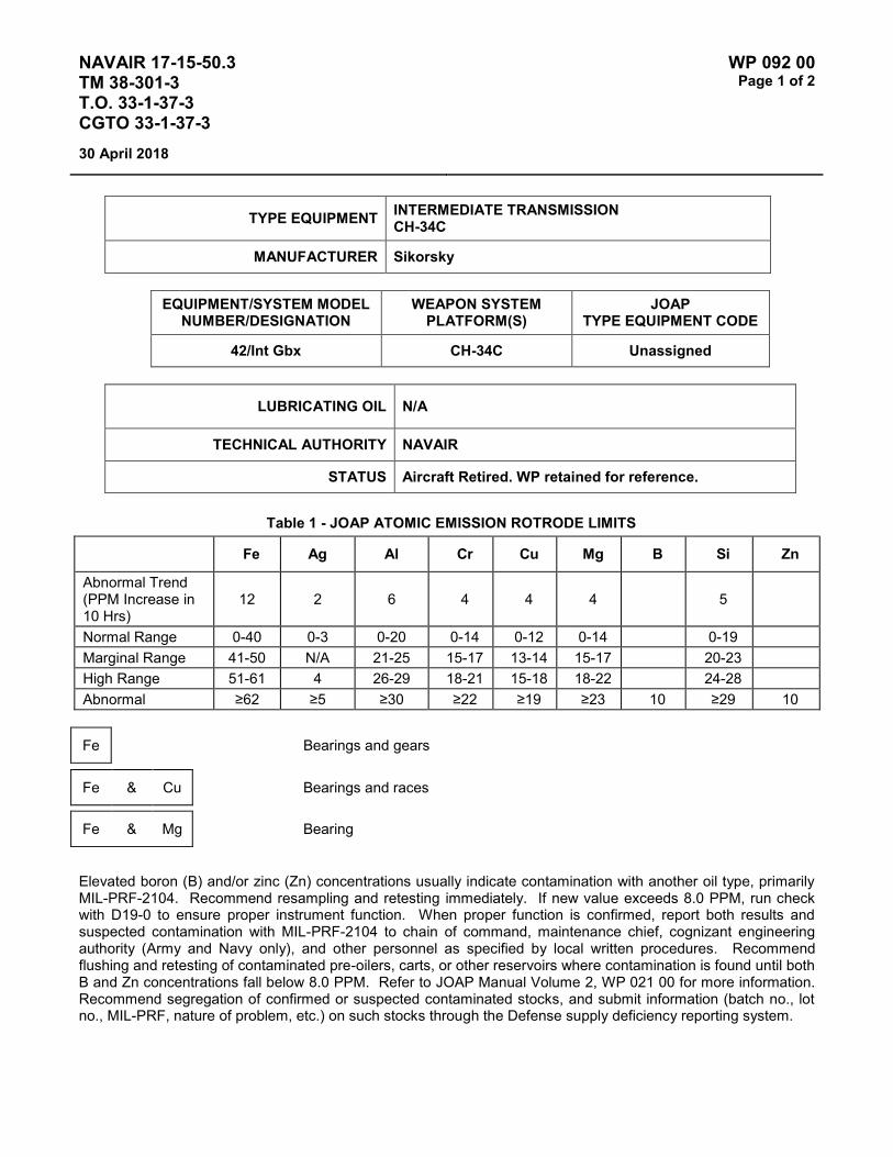
NAVAIR 17-15-50.3 TM 38-301-3 T.O. 33-1-37-3 CGTO 33-1-37-3
WP 092 00 Page 1 of 2
30 April 2018
TYPE EQUIPMENT INTERMEDIATE TRANSMISSION CH-34C
MANUFACTURER Sikorsky
EQUIPMENT/SYSTEM MODEL NUMBER/DESIGNATION
WEAPON SYSTEM PLATFORM(S)
JOAP TYPE EQUIPMENT CODE
42/Int Gbx CH-34C Unassigned
LUBRICATING OIL N/A
TECHNICAL AUTHORITY NAVAIR
STATUS Aircraft Retired. WP retained for reference.
Table 1 - JOAP ATOMIC EMISSION ROTRODE LIMITS
Fe Ag Al Cr Cu Mg B Si Zn
Abnormal Trend (PPM Increase in 10 Hrs)
12 2 6 4 4 4 5
Normal Range 0-40 0-3 0-20 0-14 0-12 0-14 0-19 Marginal Range 41-50 N/A 21-25 15-17 13-14 15-17 20-23 High Range 51-61 4 26-29 18-21 15-18 18-22 24-28 Abnormal ≥62 ≥5 ≥30 ≥22 ≥19 ≥23 10 ≥29 10
Fe Bearings and gears
Fe & Cu Bearings and races
Fe & Mg Bearing
Elevated boron (B) and/or zinc (Zn) concentrations usually indicate contamination with another oil type, primarily MIL-PRF-2104. Recommend resampling and retesting immediately. If new value exceeds 8.0 PPM, run check with D19-0 to ensure proper instrument function. When proper function is confirmed, report both results and suspected contamination with MIL-PRF-2104 to chain of command, maintenance chief, cognizant engineering authority (Army and Navy only), and other personnel as specified by local written procedures. Recommend flushing and retesting of contaminated pre-oilers, carts, or other reservoirs where contamination is found until both B and Zn concentrations fall below 8.0 PPM. Refer to JOAP Manual Volume 2, WP 021 00 for more information. Recommend segregation of confirmed or suspected contaminated stocks, and submit information (batch no., lot no., MIL-PRF, nature of problem, etc.) on such stocks through the Defense supply deficiency reporting system.

NAVAIR 17-15-50.3 TM 38-301-3 T.O. 33-1-37-3 CGTO 33-1-37-3
WP 092 00 Page 2 of 2
30 April 2018
NOTES
High concentration of Fe & Mg could also indicate corrosion due to moisture in the system.
High concentration Si indicates contamination probably due to sand and dirt or silicon rubber parts or presence of anti-foaming additive.

NAVAIR 17-15-50.3 TM 38-301-3 T.O. 33-1-37-3 CGTO 33-1-37-3
WP 093 00 Page 1 of 2
30 April 2018
TYPE EQUIPMENT TAIL ROTOR GEARBOX CH-34C
MANUFACTURER Sikorsky
EQUIPMENT/SYSTEM MODEL NUMBER/DESIGNATION
WEAPON SYSTEM PLATFORM(S)
JOAP TYPE EQUIPMENT CODE
90/Tail Gbx CH-34C Unassigned
LUBRICATING OIL N/A
TECHNICAL AUTHORITY NAVAIR
STATUS Aircraft Retired. WP retained for reference.
Table 1 - JOAP ATOMIC EMISSION ROTRODE LIMITS
Fe Ag Al Cr Cu Mg B Si Zn
Abnormal Trend (PPM Increase in 10 Hrs)
12 2 5 4 4 4 5
Normal Range 0-40 0-3 0-19 0-12 0-11 0-11 0-18 Marginal Range 41-50 N/A 20-23 13-15 12-13 12-13 19-22 High Range 51-61 4 24-28 16-17 14-16 14-16 23-26 Abnormal ≥62 ≥5 ≥29 ≥18 ≥17 ≥17 10 ≥27 10
Fe Bearings and gears
Fe & Cu Bearings and races
Fe & Mg Bearing liner rotating in housing
Fe & Al Bearing rotating in quill housing
Elevated boron (B) and/or zinc (Zn) concentrations usually indicate contamination with another oil type, primarily MIL-PRF-2104. Recommend resampling and retesting immediately. If new value exceeds 8.0 PPM, run check with D19-0 to ensure proper instrument function. When proper function is confirmed, report both results and suspected contamination with MIL-PRF-2104 to chain of command, maintenance chief, cognizant engineering authority (Army and Navy only), and other personnel as specified by local written procedures. Recommend flushing and retesting of contaminated pre-oilers, carts, or other reservoirs where contamination is found until both B and Zn concentrations fall below 8.0 PPM. Refer to JOAP Manual Volume 2, WP 021 00 for more information.

NAVAIR 17-15-50.3 TM 38-301-3 T.O. 33-1-37-3 CGTO 33-1-37-3
WP 093 00 Page 2 of 2
30 April 2018
Recommend segregation of confirmed or suspected contaminated stocks, and submit information (batch no., lot no., MIL-PRF, nature of problem, etc.) on such stocks through the Defense supply deficiency reporting system.
NOTES
High concentration of Fe & Mg could also indicate corrosion due to moisture in the system.
High concentration Si indicates contamination probably due to sand and dirt or silicon rubber parts or presence of anti-foaming additive.

NAVAIR 17-15-50.3 TM 38-301-3 T.O. 33-1-37-3 CGTO 33-1-37-3
WP 094 00 Page 1 of 2
30 April 2018
TYPE EQUIPMENT MAIN TRANSMISSION H-43
MANUFACTURER Kaman
EQUIPMENT/SYSTEM MODEL NUMBER/DESIGNATION
WEAPON SYSTEM PLATFORM(S)
JOAP TYPE EQUIPMENT CODE
Main Xmsn H-43 Unassigned
LUBRICATING OIL N/A
TECHNICAL AUTHORITY Air Force
STATUS Aircraft Retired. WP retained for reference.
Table 1 - JOAP ATOMIC EMISSION ROTRODE LIMITS
Fe Ag Al Cr Cu Mg B Si Zn
Abnormal Trend (PPM Increase in 10 Hrs)
12 2 4 2 3 3
Normal Range 0-39 0-3 0-10 0-3 0-6 0-6 Marginal Range 40-48 N/A 11-12 N/A 7 7 High Range 49-59 4 13-14 4 8-9 8-9 Abnormal ≥60 ≥5 ≥15 ≥5 ≥10 ≥10 10 10 10
Samples frequently contaminated; when this occurs all wear metals will be high; recommend resample.
Elevated boron (B) and/or zinc (Zn) concentrations usually indicate contamination with another oil type, primarily MIL-PRF-2104. Recommend resampling and retesting immediately. If new value exceeds 8.0 PPM, run check with D19-0 to ensure proper instrument function. When proper function is confirmed, report both results and suspected contamination with MIL-PRF-2104 to chain of command, maintenance chief, cognizant engineering authority (Army and Navy only), and other personnel as specified by local written procedures. Recommend flushing and retesting of contaminated pre-oilers, carts, or other reservoirs where contamination is found until both B and Zn concentrations fall below 8.0 PPM. Refer to JOAP Manual Volume 2, WP 021 00 for more information. Recommend segregation of confirmed or suspected contaminated stocks, and submit information (batch no., lot no., MIL-PRF, nature of problem, etc.) on such stocks through the Defense supply deficiency reporting system.
Elevated silicon (Si) concentration usually indicates contamination with soil, sand, or dust. If aluminum (Al) is also elevated, this suggests the presence of clay or soil. Recommend resampling and retesting immediately. If new value exceeds 8.0 PPM, run check with D19-0 to ensure proper instrument function. When proper function is confirmed, report both results and suspected contamination with soil, sand, or dust to chain of command, maintenance chief, cognizant engineering authority (Army and Navy only), and other personnel as specified by local written procedures. Recommend flushing and retesting of contaminated pre-oilers, carts, or other reservoirs

NAVAIR 17-15-50.3 TM 38-301-3 T.O. 33-1-37-3 CGTO 33-1-37-3
WP 094 00 Page 2 of 2
30 April 2018
where contamination is found until silicon concentration falls below 8.0 PPM. Refer to JOAP Manual Volume 2, WP 021 00 for more information. Recommend segregation of confirmed or suspected contaminated stocks, and submit information (batch no., lot no., MIL-PRF, nature of problem, etc.) on such stocks through the Defense supply deficiency reporting system.

NAVAIR 17-15-50.3 TM 38-301-3 T.O. 33-1-37-3 CGTO 33-1-37-3
WP 095 00 Page 1 of 2
30 April 2018
TYPE EQUIPMENT FORWARD GEARBOX H-46 (NAVY / USMC)
MANUFACTURER Boeing Vertol
EQUIPMENT/SYSTEM MODEL NUMBER/DESIGNATION
WEAPON SYSTEM PLATFORM(S)
JOAP TYPE EQUIPMENT CODE
Fwd Xmsn H-46 GDFA
LUBRICATING OIL DOD-PRF-85734 (Alternative oil: MIL-PRF-23699 or MIL-PRF-7808)
TECHNICAL AUTHORITY NAVAIRSYSCOM
STATUS In Use
Table 1 - JOAP ATOMIC EMISSION ROTRODE LIMITS
Fe Ag Al Cr Cu Mg B Si Zn
Abnormal Trend (PPM Increase in 10 Hrs)
13 12 4 5
Normal Range 0-42 0-40 0-10 0-17 Marginal Range 43-52 41-50 11-12 18-21 High Range 53-63 51-58 13-14 22-25 Abnormal ≥64 ≥59 ≥15 ≥26 10 10 10
Fe Bearing assemblies
Cu Sump filter or inlet filter, bearing cages
Al & Fe Upper case and bearing assemblies
Mg & Fe Lower case and bearing assemblies, corrosion
Elevated boron (B) and/or zinc (Zn) concentrations usually indicate contamination with another oil type, primarily MIL-PRF-2104. Recommend resampling and retesting immediately. If new value exceeds 8.0 PPM, run check with D19-0 to ensure proper instrument function. When proper function is confirmed, report both results and suspected contamination with MIL-PRF-2104 to chain of command, maintenance chief, cognizant engineering authority (Army and Navy only), and other personnel as specified by local written procedures. Recommend flushing and retesting of contaminated pre-oilers, carts, or other reservoirs where contamination is found until both B and Zn concentrations fall below 8.0 PPM. Refer to JOAP Manual Volume 2, WP 021 00 for more information. Recommend segregation of confirmed or suspected contaminated stocks, and submit information (batch no., lot

NAVAIR 17-15-50.3 TM 38-301-3 T.O. 33-1-37-3 CGTO 33-1-37-3
WP 095 00 Page 2 of 2
30 April 2018
no., MIL-PRF, nature of problem, etc.) on such stocks through the Defense supply deficiency reporting system.
Elevated silicon (Si) concentration usually indicates contamination with soil, sand, or dust. If aluminum (Al) is also elevated, this suggests the presence of clay or soil. Recommend resampling and retesting immediately. If new value exceeds 8.0 PPM, run check with D19-0 to ensure proper instrument function. When proper function is confirmed, report both results and suspected contamination with soil, sand, or dust to chain of command, maintenance chief, cognizant engineering authority (Army and Navy only), and other personnel as specified by local written procedures. Recommend flushing and retesting of contaminated pre-oilers, carts, or other reservoirs where contamination is found until silicon concentration falls below 8.0 PPM. Refer to JOAP Manual Volume 2, WP 021 00 for more information. Recommend segregation of confirmed or suspected contaminated stocks, and submit information (batch no., lot no., MIL-PRF, nature of problem, etc.) on such stocks through the Defense supply deficiency reporting system.

NAVAIR 17-15-50.3 TM 38-301-3 T.O. 33-1-37-3 CGTO 33-1-37-3
WP 096 00 Page 1 of 2
30 April 2018
TYPE EQUIPMENT AFT GEARBOX H-46 (NAVY / USMC)
MANUFACTURER Boeing Vertol
EQUIPMENT/SYSTEM MODEL NUMBER/DESIGNATION
WEAPON SYSTEM PLATFORM(S)
JOAP TYPE EQUIPMENT CODE
Aft Xmsn H-46 GDAA
LUBRICATING OIL DOD-PRF-85734 (Alternative oil: MIL-PRF-23699 or MIL-PRF-7808)
TECHNICAL AUTHORITY NAVAIRSYSCOM
STATUS In Use
Table 1 - JOAP ATOMIC EMISSION ROTRODE LIMITS
Fe Ag Al Cr Cu Mg B Si Zn
Abnormal Trend (PPM Increase in 10 Hrs)
14 12 5 5
Normal Range 0-46 0-40 0-17 0-17 Marginal Range 47-56 41-50 18-21 18-21 High Range 57-69 51-58 22-25 22-25 Abnormal ≥70 ≥59 ≥26 ≥26 10 10 10
Fe Bearing assemblies
Fe & Cu Bearing assemblies
Fe & Mg Bearings and transmission cases
Elevated boron (B) and/or zinc (Zn) concentrations usually indicate contamination with another oil type, primarily MIL-PRF-2104. Recommend resampling and retesting immediately. If new value exceeds 8.0 PPM, run check with D19-0 to ensure proper instrument function. When proper function is confirmed, report both results and suspected contamination with MIL-PRF-2104 to chain of command, maintenance chief, cognizant engineering authority (Army and Navy only), and other personnel as specified by local written procedures. Recommend flushing and retesting of contaminated pre-oilers, carts, or other reservoirs where contamination is found until both B and Zn concentrations fall below 8.0 PPM. Refer to JOAP Manual Volume 2, WP 021 00 for more information. Recommend segregation of confirmed or suspected contaminated stocks, and submit information (batch no., lot no., MIL-PRF, nature of problem, etc.) on such stocks through the Defense supply deficiency reporting system.

NAVAIR 17-15-50.3 TM 38-301-3 T.O. 33-1-37-3 CGTO 33-1-37-3
WP 096 00 Page 2 of 2
30 April 2018
Elevated silicon (Si) concentration usually indicates contamination with soil, sand, or dust. If aluminum (Al) is also elevated, this suggests the presence of clay or soil. Recommend resampling and retesting immediately. If new value exceeds 8.0 PPM, run check with D19-0 to ensure proper instrument function. When proper function is confirmed, report both results and suspected contamination with soil, sand, or dust to chain of command, maintenance chief, cognizant engineering authority (Army and Navy only), and other personnel as specified by local written procedures. Recommend flushing and retesting of contaminated pre-oilers, carts, or other reservoirs where contamination is found until silicon concentration falls below 8.0 PPM. Refer to JOAP Manual Volume 2, WP 021 00 for more information. Recommend segregation of confirmed or suspected contaminated stocks, and submit information (batch no., lot no., MIL-PRF, nature of problem, etc.) on such stocks through the Defense supply deficiency reporting system.
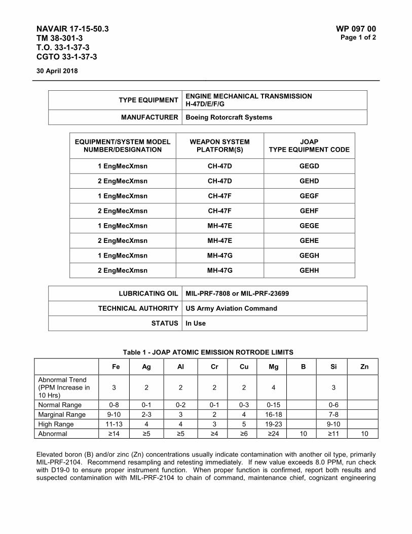
NAVAIR 17-15-50.3 TM 38-301-3 T.O. 33-1-37-3 CGTO 33-1-37-3
WP 097 00 Page 1 of 2
30 April 2018
TYPE EQUIPMENT ENGINE MECHANICAL TRANSMISSION H-47D/E/F/G
MANUFACTURER Boeing Rotorcraft Systems
EQUIPMENT/SYSTEM MODEL NUMBER/DESIGNATION
WEAPON SYSTEM PLATFORM(S)
JOAP TYPE EQUIPMENT CODE
1 EngMecXmsn CH-47D GEGD
2 EngMecXmsn CH-47D GEHD
1 EngMecXmsn CH-47F GEGF
2 EngMecXmsn CH-47F GEHF
1 EngMecXmsn MH-47E GEGE
2 EngMecXmsn MH-47E GEHE
1 EngMecXmsn MH-47G GEGH
2 EngMecXmsn MH-47G GEHH
LUBRICATING OIL MIL-PRF-7808 or MIL-PRF-23699
TECHNICAL AUTHORITY US Army Aviation Command
STATUS In Use
Table 1 - JOAP ATOMIC EMISSION ROTRODE LIMITS
Fe Ag Al Cr Cu Mg B Si Zn
Abnormal Trend (PPM Increase in 10 Hrs)
3 2 2 2 2 4 3
Normal Range 0-8 0-1 0-2 0-1 0-3 0-15 0-6 Marginal Range 9-10 2-3 3 2 4 16-18 7-8 High Range 11-13 4 4 3 5 19-23 9-10 Abnormal ≥14 ≥5 ≥5 ≥4 ≥6 ≥24 10 ≥11 10
Elevated boron (B) and/or zinc (Zn) concentrations usually indicate contamination with another oil type, primarily MIL-PRF-2104. Recommend resampling and retesting immediately. If new value exceeds 8.0 PPM, run check with D19-0 to ensure proper instrument function. When proper function is confirmed, report both results and suspected contamination with MIL-PRF-2104 to chain of command, maintenance chief, cognizant engineering

NAVAIR 17-15-50.3 TM 38-301-3 T.O. 33-1-37-3 CGTO 33-1-37-3
WP 097 00 Page 2 of 2
30 April 2018
authority (Army and Navy only), and other personnel as specified by local written procedures. Recommend flushing and retesting of contaminated pre-oilers, carts, or other reservoirs where contamination is found until both B and Zn concentrations fall below 8.0 PPM. Refer to JOAP Manual Volume 2, WP 021 00 for more information. Recommend segregation of confirmed or suspected contaminated stocks, and submit information (batch no., lot no., MIL-PRF, nature of problem, etc.) on such stocks through the Defense supply deficiency reporting system.
Elevated silicon (Si) concentration usually indicates contamination with soil, sand, or dust. If aluminum (Al) is also elevated, this suggests the presence of clay or soil. Recommend resampling and retesting immediately. If new value exceeds 8.0 PPM, run check with D19-0 to ensure proper instrument function. When proper function is confirmed, report both results and suspected contamination with soil, sand, or dust to chain of command, maintenance chief, cognizant engineering authority (Army and Navy only), and other personnel as specified by local written procedures. Recommend flushing and retesting of contaminated pre-oilers, carts, or other reservoirs where contamination is found until silicon concentration falls below 8.0 PPM. Refer to JOAP Manual Volume 2, WP 021 00 for more information. Recommend segregation of confirmed or suspected contaminated stocks, and submit information (batch no., lot no., MIL-PRF, nature of problem, etc.) on such stocks through the Defense supply deficiency reporting system.

NAVAIR 17-15-50.3 TM 38-301-3 T.O. 33-1-37-3 CGTO 33-1-37-3
WP 098 00 Page 1 of 2
30 April 2018
TYPE EQUIPMENT COMBINING TRANSMISSION H-47D/E/F/G
MANUFACTURER Boeing Rotorcraft Systems
EQUIPMENT/SYSTEM MODEL NUMBER/DESIGNATION
WEAPON SYSTEM PLATFORM(S)
JOAP TYPE EQUIPMENT CODE
Eng Comb Xmsn CH-47D GEED
Eng Comb Xmsn CH-47F GEEF
Eng Comb Xmsn MH-47E GEEE
Eng Comb Xmsn MH-47G GEEH
LUBRICATING OIL MIL-PRF-7808 or MIL-PRF-23699
TECHNICAL AUTHORITY US Army Aviation Command
STATUS In Use
Table 1 - JOAP ATOMIC EMISSION ROTRODE LIMITS
Fe Ag Al Cr Cu Mg B Si Zn
Abnormal Trend (PPM Increase in 10 Hrs)
3 2 2 2 2 4 3
Normal Range 0-8 1 0-2 1 0-2 0-14 0-7 Marginal Range 9-10 2 3 2 3 15-18 8-9 High Range 11-13 3 4 3 4 19-22 10 Abnormal ≥14 ≥4 ≥5 ≥4 ≥5 ≥23 10 ≥11 10
Elevated boron (B) and/or zinc (Zn) concentrations usually indicate contamination with another oil type, primarily MIL-PRF-2104. Recommend resampling and retesting immediately. If new value exceeds 8.0 PPM, run check with D19-0 to ensure proper instrument function. When proper function is confirmed, report both results and suspected contamination with MIL-PRF-2104 to chain of command, maintenance chief, cognizant engineering authority (Army and Navy only), and other personnel as specified by local written procedures. Recommend flushing and retesting of contaminated pre-oilers, carts, or other reservoirs where contamination is found until both B and Zn concentrations fall below 8.0 PPM. Refer to JOAP Manual Volume 2, WP 021 00 for more information. Recommend segregation of confirmed or suspected contaminated stocks, and submit information (batch no., lot no., MIL-PRF, nature of problem, etc.) on such stocks through the Defense supply deficiency reporting system.
Elevated silicon (Si) concentration usually indicates contamination with soil, sand, or dust. If aluminum (Al) is also elevated, this suggests the presence of clay or soil. Recommend resampling and retesting immediately. If new value exceeds 8.0 PPM, run check with D19-0 to ensure proper instrument function. When proper function is

NAVAIR 17-15-50.3 TM 38-301-3 T.O. 33-1-37-3 CGTO 33-1-37-3
WP 098 00 Page 2 of 2
30 April 2018
confirmed, report both results and suspected contamination with soil, sand, or dust to chain of command, maintenance chief, cognizant engineering authority (Army and Navy only), and other personnel as specified by local written procedures. Recommend flushing and retesting of contaminated pre-oilers, carts, or other reservoirs where contamination is found until silicon concentration falls below 8.0 PPM. Refer to JOAP Manual Volume 2, WP 021 00 for more information. Recommend segregation of confirmed or suspected contaminated stocks, and submit information (batch no., lot no., MIL-PRF, nature of problem, etc.) on such stocks through the Defense supply deficiency reporting system.
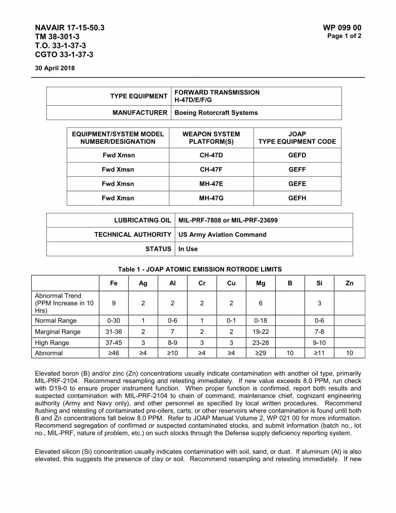
NAVAIR 17-15-50.3 TM 38-301-3 T.O. 33-1-37-3 CGTO 33-1-37-3
WP 099 00 Page 1 of 2
30 April 2018
TYPE EQUIPMENT FORWARD TRANSMISSION H-47D/E/F/G
MANUFACTURER Boeing Rotorcraft Systems
EQUIPMENT/SYSTEM MODEL NUMBER/DESIGNATION
WEAPON SYSTEM PLATFORM(S)
JOAP TYPE EQUIPMENT CODE
Fwd Xmsn CH-47D GEFD
Fwd Xmsn CH-47F GEFF
Fwd Xmsn MH-47E GEFE
Fwd Xmsn MH-47G GEFH
LUBRICATING OIL MIL-PRF-7808 or MIL-PRF-23699
TECHNICAL AUTHORITY US Army Aviation Command
STATUS In Use
Table 1 - JOAP ATOMIC EMISSION ROTRODE LIMITS
Fe Ag Al Cr Cu Mg B Si Zn
Abnormal Trend (PPM Increase in 10 Hrs)
9 2 2 2 2 6 3
Normal Range 0-30 1 0-6 1 0-1 0-18 0-6
Marginal Range 31-36 2 7 2 2 19-22 7-8
High Range 37-45 3 8-9 3 3 23-28 9-10 Abnormal ≥46 ≥4 ≥10 ≥4 ≥4 ≥29 10 ≥11 10
Elevated boron (B) and/or zinc (Zn) concentrations usually indicate contamination with another oil type, primarily MIL-PRF-2104. Recommend resampling and retesting immediately. If new value exceeds 8.0 PPM, run check with D19-0 to ensure proper instrument function. When proper function is confirmed, report both results and suspected contamination with MIL-PRF-2104 to chain of command, maintenance chief, cognizant engineering authority (Army and Navy only), and other personnel as specified by local written procedures. Recommend flushing and retesting of contaminated pre-oilers, carts, or other reservoirs where contamination is found until both B and Zn concentrations fall below 8.0 PPM. Refer to JOAP Manual Volume 2, WP 021 00 for more information. Recommend segregation of confirmed or suspected contaminated stocks, and submit information (batch no., lot no., MIL-PRF, nature of problem, etc.) on such stocks through the Defense supply deficiency reporting system.
Elevated silicon (Si) concentration usually indicates contamination with soil, sand, or dust. If aluminum (Al) is also elevated, this suggests the presence of clay or soil. Recommend resampling and retesting immediately. If new

NAVAIR 17-15-50.3 TM 38-301-3 T.O. 33-1-37-3 CGTO 33-1-37-3
WP 099 00 Page 2 of 2
30 April 2018
value exceeds 8.0 PPM, run check with D19-0 to ensure proper instrument function. When proper function is confirmed, report both results and suspected contamination with soil, sand, or dust to chain of command, maintenance chief, cognizant engineering authority (Army and Navy only), and other personnel as specified by local written procedures. Recommend flushing and retesting of contaminated pre-oilers, carts, or other reservoirs where contamination is found until silicon concentration falls below 8.0 PPM. Refer to JOAP Manual Volume 2, WP 021 00 for more information. Recommend segregation of confirmed or suspected contaminated stocks, and submit information (batch no., lot no., MIL-PRF, nature of problem, etc.) on such stocks through the Defense supply deficiency reporting system.

NAVAIR 17-15-50.3 TM 38-301-3 T.O. 33-1-37-3 CGTO 33-1-37-3
WP 100 00 Page 1 of 2
30 April 2018
TYPE EQUIPMENT Aft Transmission H-47D/E/F/G
MANUFACTURER Boeing
EQUIPMENT/SYSTEM MODEL NUMBER/DESIGNATION
WEAPON SYSTEM PLATFORM(S)
JOAP TYPE EQUIPMENT CODE
Aft Xmsn CH-47D GEAD
Aft Xmsn CH-47F GEAF
Aft Xmsn MH-47E GEAE
Aft Xmsn MH-47G GEAH
LUBRICATING OIL MIL-PRF-7808 or MIL-PRF-23699
TECHNICAL AUTHORITY US Army Aviation Command
STATUS In Use
Table 1 - JOAP ATOMIC EMISSION ROTRODE LIMITS
Fe Ag Al Cr Cu Mg B Si Zn
Abnormal Trend (PPM Increase in 10 Hrs)
9 2 2 2 2 10 10
Normal Range 0-27 1 0-4 1 0-2 0-33 0-32 Marginal Range 28-33 2 5 2 3 34-40 33-40 High Range 34-41 3 6 3 4 41-50 41-50 Abnormal ≥42 ≥4 ≥7 ≥4 ≥5 ≥51 10 ≥51 10
Elevated boron (B) and/or zinc (Zn) concentrations usually indicate contamination with another oil type, primarily MIL-PRF-2104. Recommend resampling and retesting immediately. If new value exceeds 8.0 PPM, run check with D19-0 to ensure proper instrument function. When proper function is confirmed, report both results and suspected contamination with MIL-PRF-2104 to chain of command, maintenance chief, cognizant engineering authority (Army and Navy only), and other personnel as specified by local written procedures. Recommend flushing and retesting of contaminated pre-oilers, carts, or other reservoirs where contamination is found until both B and Zn concentrations fall below 8.0 PPM. Refer to JOAP Manual Volume 2, WP 021 00 for more information. Recommend segregation of confirmed or suspected contaminated stocks, and submit information (batch no., lot no., MIL-PRF, nature of problem, etc.) on such stocks through the Defense supply deficiency reporting system.

NAVAIR 17-15-50.3 TM 38-301-3 T.O. 33-1-37-3 CGTO 33-1-37-3
WP 100 00 Page 2 of 2
30 April 2018
This Page Intentionally Left Blank

NAVAIR 17-15-50.3 TM 38-301-3 T.O. 33-1-37-3 CGTO 33-1-37-3
WP 101 00 Page 1 of 2
30 April 2018
TYPE EQUIPMENT MAIN TRANSMISSION HH-52 (NAVY AND COAST GUARD)
MANUFACTURER Sikorsky
EQUIPMENT/SYSTEM MODEL NUMBER/DESIGNATION
WEAPON SYSTEM PLATFORM(S)
JOAP TYPE EQUIPMENT CODE
Main Xmsn HH-52 GRMA
LUBRICATING OIL MIL-PRF-23699
TECHNICAL AUTHORITY NAVAIR
STATUS Aircraft Retired. WP retained for reference.
Table 1 - JOAP ATOMIC EMISSION ROTRODE LIMITS
Fe Ag Al Cr Cu Mg B Si Zn
Abnormal Trend (PPM Increase in 10 Hrs)
23 6 8
Normal Range 0-76 0-20 0-26 Marginal Range 77-88 21-25 27-32 High Range 89-114 26-29 33-39 Abnormal ≥115 ≥30 ≥40 10 10 10
Copper is commonly manifest in low-time boxes as extremely thin, foil-like flakes of bright copper in the chip detector, screen, and filters. It often shows up during the post run-in filter checks on green gearboxes. Contamination of this requires a serviceability check to verify that it is benign, and will generally diminish drastically within about 10 flight hours. Continue to be wary of any contamination in the form of granules or chunks.
Contamination may also be detected during spectrometric analysis of gearbox oil, particularly in a high-time box, and the copper level may exceed published limits. In that case, check the filters and perform a serviceability check if necessary. Barring secondary indications, continue the gearbox in service and monitor gradual copper increases.
Elevated boron (B) and/or zinc (Zn) concentrations usually indicate contamination with another oil type, primarily MIL-PRF-2104. Recommend resampling and retesting immediately. If new value exceeds 8.0 PPM, run check with D19-0 to ensure proper instrument function. When proper function is confirmed, report both results and suspected contamination with MIL-PRF-2104 to chain of command, maintenance chief, cognizant engineering authority (Army and Navy only), and other personnel as specified by local written procedures. Recommend flushing and retesting of contaminated pre-oilers, carts, or other reservoirs where contamination is found until both B and Zn concentrations fall below 8.0 PPM. Refer to JOAP Manual Volume 2, WP 021 00 for more information. Recommend segregation of confirmed or suspected contaminated stocks, and submit information (batch no., lot

NAVAIR 17-15-50.3 TM 38-301-3 T.O. 33-1-37-3 CGTO 33-1-37-3
WP 101 00 Page 2 of 2
30 April 2018
no., MIL-PRF, nature of problem, etc.) on such stocks through the Defense supply deficiency reporting system.
Elevated silicon (Si) concentration usually indicates contamination with soil, sand, or dust. If aluminum (Al) is also elevated, this suggests the presence of clay or soil. Recommend resampling and retesting immediately. If new value exceeds 8.0 PPM, run check with D19-0 to ensure proper instrument function. When proper function is confirmed, report both results and suspected contamination with soil, sand, or dust to chain of command, maintenance chief, cognizant engineering authority (Army and Navy only), and other personnel as specified by local written procedures. Recommend flushing and retesting of contaminated pre-oilers, carts, or other reservoirs where contamination is found until silicon concentration falls below 8.0 PPM. Refer to JOAP Manual Volume 2, WP 021 00 for more information. Recommend segregation of confirmed or suspected contaminated stocks, and submit information (batch no., lot no., MIL-PRF, nature of problem, etc.) on such stocks through the Defense supply deficiency reporting system.
Cu Flash copper plating on planetary gears

NAVAIR 17-15-50.3 TM 38-301-3 T.O. 33-1-37-3 CGTO 33-1-37-3
WP 102 00 Page 1 of 2
30 April 2018
TYPE EQUIPMENT INTERMEDIATE TRANSMISSION HH-52 (NAVY AND COAST GUARD)
MANUFACTURER Sikorsky
EQUIPMENT/SYSTEM MODEL NUMBER/DESIGNATION
WEAPON SYSTEM PLATFORM(S)
JOAP TYPE EQUIPMENT CODE
42/Int Gbx HH-52 GRIA
LUBRICATING OIL MIL-PRF-23699
TECHNICAL AUTHORITY NAVAIR
STATUS Aircraft Retired. WP retained for reference.
Table 1 - JOAP ATOMIC EMISSION ROTRODE LIMITS
Fe Ag Al Cr Cu Mg B Si Zn
Abnormal Trend (PPM Increase in 10 Hrs)
12 6 8
Normal Range 0-124 0-20 0-26 Marginal Range 125-144 21-25 27-32 High Range 145-164 26-29 33-39 Abnormal ≥165 ≥30 ≥40 10 10 10
Elevated boron (B) and/or zinc (Zn) concentrations usually indicate contamination with another oil type, primarily MIL-PRF-2104. Recommend resampling and retesting immediately. If new value exceeds 8.0 PPM, run check with D19-0 to ensure proper instrument function. When proper function is confirmed, report both results and suspected contamination with MIL-PRF-2104 to chain of command, maintenance chief, cognizant engineering authority (Army and Navy only), and other personnel as specified by local written procedures. Recommend flushing and retesting of contaminated pre-oilers, carts, or other reservoirs where contamination is found until both B and Zn concentrations fall below 8.0 PPM. Refer to JOAP Manual Volume 2, WP 021 00 for more information. Recommend segregation of confirmed or suspected contaminated stocks, and submit information (batch no., lot no., MIL-PRF, nature of problem, etc.) on such stocks through the Defense supply deficiency reporting system.
Elevated silicon (Si) concentration usually indicates contamination with soil, sand, or dust. If aluminum (Al) is also elevated, this suggests the presence of clay or soil. Recommend resampling and retesting immediately. If new value exceeds 8.0 PPM, run check with D19-0 to ensure proper instrument function. When proper function is confirmed, report both results and suspected contamination with soil, sand, or dust to chain of command, maintenance chief, cognizant engineering authority (Army and Navy only), and other personnel as specified by local written procedures. Recommend flushing and retesting of contaminated pre-oilers, carts, or other reservoirs where contamination is found until silicon concentration falls below 8.0 PPM. Refer to JOAP Manual Volume 2, WP 021 00 for more information. Recommend segregation of confirmed or suspected contaminated stocks, and

NAVAIR 17-15-50.3 TM 38-301-3 T.O. 33-1-37-3 CGTO 33-1-37-3
WP 102 00 Page 2 of 2
30 April 2018
submit information (batch no., lot no., MIL-PRF, nature of problem, etc.) on such stocks through the Defense supply deficiency reporting system.

NAVAIR 17-15-50.3 TM 38-301-3 T.O. 33-1-37-3 CGTO 33-1-37-3
WP 103 00 Page 1 of 2
30 April 2018
TYPE EQUIPMENT TAIL ROTOR GEARBOX HH-52 (NAVY AND COAST GUARD)
MANUFACTURER Sikorsky
EQUIPMENT/SYSTEM MODEL NUMBER/DESIGNATION
WEAPON SYSTEM PLATFORM(S)
JOAP TYPE EQUIPMENT CODE
90/Tail Gbx HH-52 GRTA
LUBRICATING OIL MIL-PRF-23699
TECHNICAL AUTHORITY NAVAIR
STATUS Aircraft Retired. WP retained for reference.
Table 1 - JOAP ATOMIC EMISSION ROTRODE LIMITS
Fe Ag Al Cr Cu Mg B Si Zn
Abnormal Trend (PPM Increase in 10 Hrs)
12 6 8
Normal Range 0-124 0-20 0-26 Marginal Range 125-144 21-25 27-32 High Range 145-164 26-29 33-39 Abnormal ≥165 ≥30 ≥40 10 10 10
Elevated boron (B) and/or zinc (Zn) concentrations usually indicate contamination with another oil type, primarily MIL-PRF-2104. Recommend resampling and retesting immediately. If new value exceeds 8.0 PPM, run check with D19-0 to ensure proper instrument function. When proper function is confirmed, report both results and suspected contamination with MIL-PRF-2104 to chain of command, maintenance chief, cognizant engineering authority (Army and Navy only), and other personnel as specified by local written procedures. Recommend flushing and retesting of contaminated pre-oilers, carts, or other reservoirs where contamination is found until both B and Zn concentrations fall below 8.0 PPM. Refer to JOAP Manual Volume 2, WP 021 00 for more information. Recommend segregation of confirmed or suspected contaminated stocks, and submit information (batch no., lot no., MIL-PRF, nature of problem, etc.) on such stocks through the Defense supply deficiency reporting system.
Elevated silicon (Si) concentration usually indicates contamination with soil, sand, or dust. If aluminum (Al) is also elevated, this suggests the presence of clay or soil. Recommend resampling and retesting immediately. If new value exceeds 8.0 PPM, run check with D19-0 to ensure proper instrument function. When proper function is confirmed, report both results and suspected contamination with soil, sand, or dust to chain of command, maintenance chief, cognizant engineering authority (Army and Navy only), and other personnel as specified by local written procedures. Recommend flushing and retesting of contaminated pre-oilers, carts, or other reservoirs where contamination is found until silicon concentration falls below 8.0 PPM. Refer to JOAP Manual Volume 2, WP 021 00 for more information. Recommend segregation of confirmed or suspected contaminated stocks, and

NAVAIR 17-15-50.3 TM 38-301-3 T.O. 33-1-37-3 CGTO 33-1-37-3
WP 103 00 Page 2 of 2
30 April 2018
submit information (batch no., lot no., MIL-PRF, nature of problem, etc.) on such stocks through the Defense supply deficiency reporting system.
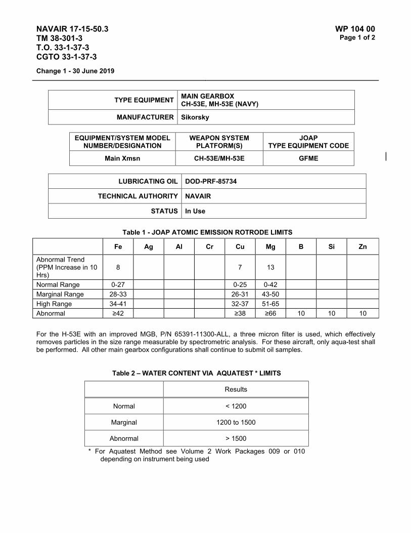
NAVAIR 17-15-50.3 TM 38-301-3 T.O. 33-1-37-3 CGTO 33-1-37-3
WP 104 00 Page 1 of 2
Change 1 - 30 June 2019
TYPE EQUIPMENT MAIN GEARBOX CH-53E, MH-53E (NAVY)
MANUFACTURER Sikorsky
EQUIPMENT/SYSTEM MODEL NUMBER/DESIGNATION
WEAPON SYSTEM PLATFORM(S)
JOAP TYPE EQUIPMENT CODE
Main Xmsn CH-53E/MH-53E GFME
LUBRICATING OIL DOD-PRF-85734
TECHNICAL AUTHORITY NAVAIR
STATUS In Use
Table 1 - JOAP ATOMIC EMISSION ROTRODE LIMITS
Fe Ag Al Cr Cu Mg B Si Zn
Abnormal Trend (PPM Increase in 10 Hrs)
8 7 13
Normal Range 0-27 0-25 0-42 Marginal Range 28-33 26-31 43-50 High Range 34-41 32-37 51-65 Abnormal ≥42 ≥38 ≥66 10 10 10
For the H-53E with an improved MGB, P/N 65391-11300-ALL, a three micron filter is used, which effectively removes particles in the size range measurable by spectrometric analysis. For these aircraft, only aqua-test shall be performed. All other main gearbox configurations shall continue to submit oil samples.
Table 2 – WATER CONTENT VIA AQUATEST * LIMITS
Results
Normal < 1200
Marginal 1200 to 1500
Abnormal > 1500
* For Aquatest Method see Volume 2 Work Packages 009 or 010 depending on instrument being used

NAVAIR 17-15-50.3 TM 38-301-3 T.O. 33-1-37-3 CGTO 33-1-37-3
WP 104 00 Page 2 of 2
Change 1 - 30 June 2019
For all MGBs. water content limit shall be 1200 PPM (0.120 percent). For all configurations of MGB, water content that exceeds 1500 PPM shall result in a laboratory recommendation of *J": Change oil; sample after first flight. Water content between 1200 and 1500 PPM shall result in a laboratory recommendation "C": Do not change oil; resample after first flight. If resample results in water content still above 1200 PPM, laboratory recommendation shall be "J": Change oil; sample after first flight.
Water in the oil could cause high iron, copper, magnesium, or aluminum due to corrosion. If high or abnormal wear metals are obtained and high water is detected on two consecutive samples, the laboratory recommendations may be to drain gearbox, reservice and perform serviceability check. Info CFA when recommending flushing.
Elevated boron (B) and/or zinc (Zn) concentrations usually indicate contamination with another oil type, primarily MIL-PRF-2104. Recommend resampling and retesting immediately. If new value exceeds 8.0 PPM, run check with D19-0 to ensure proper instrument function. When proper function is confirmed, report both results and suspected contamination with MIL-PRF-2104 to chain of command, maintenance chief, cognizant engineering authority (Army and Navy only), and other personnel as specified by local written procedures. Recommend flushing and retesting of contaminated pre-oilers, carts, or other reservoirs where contamination is found until both B and Zn concentrations fall below 8.0 PPM. Refer to JOAP Manual Volume 2, WP 021 00 for more information. Recommend segregation of confirmed or suspected contaminated stocks, and submit information (batch no., lot no., MIL-PRF, nature of problem, etc.) on such stocks through the Defense supply deficiency reporting system.
Elevated silicon (Si) concentration usually indicates contamination with soil, sand, or dust. If aluminum (Al) is also elevated, this suggests the presence of clay or soil. Recommend resampling and retesting immediately. If new value exceeds 8.0 PPM, run check with D19-0 to ensure proper instrument function. When proper function is confirmed, report both results and suspected contamination with soil, sand, or dust to chain of command, maintenance chief, cognizant engineering authority (Army and Navy only), and other personnel as specified by local written procedures. Recommend flushing and retesting of contaminated pre-oilers, carts, or other reservoirs where contamination is found until silicon concentration falls below 8.0 PPM. Refer to JOAP Manual Volume 2, WP 021 00 for more information. Recommend segregation of confirmed or suspected contaminated stocks, and submit information (batch no., lot no., MIL-PRF, nature of problem, etc.) on such stocks through the Defense supply deficiency reporting system.
NOTES
Special samples may be recommended anytime unusual readings are obtained.
High metal readings without high water may result in a laboratory recommendation for flushing or removal of a gearbox. A minimum of two consecutive high readings is required prior to recommending flushing or removing gearbox unless other evidence (chiplights, fragments, unusual noise, etc.) is found. Info CFA when recommending flushing. CFA concurrence is required prior to a recommendation for gearbox removal due to high readings. Furnish CFA with 5 previous NOAP readings when recommending gearbox removal.

NAVAIR 17-15-50.3 TM 38-301-3 T.O. 33-1-37-3 CGTO 33-1-37-3
WP 105 00 Page 1 of 2
Change 1 - 30 June 2019
TYPE EQUIPMENT INTERMEDIATE GEARBOX CH-53E, MH-53E (NAVY)
MANUFACTURER Sikorsky
EQUIPMENT/SYSTEM MODEL NUMBER/DESIGNATION
WEAPON SYSTEM PLATFORM(S)
JOAP TYPE EQUIPMENT CODE
42/Int Gbx CH-53E/MH-53E GFIE
LUBRICATING OIL DOD-PRF-85734
TECHNICAL AUTHORITY NAVAIR
STATUS In Use
Table 1 - JOAP ATOMIC EMISSION ROTRODE LIMITS
Fe Ag Al Cr Cu Mg B Si Zn
Abnormal Trend (PPM Increase in 10 Hrs)
14 4 6
Normal Range 0-46 0-13 0-20 Marginal Range 47-56 14-16 21-25 High Range 57-69 17-19 26-30 Abnormal ≥70 ≥20 ≥31 10 10 10
Table 2 – WATER CONTENT VIA AQUATEST * LIMITS
Results
Normal < 1200
Marginal 1200 to 1500
Abnormal > 1500
* For Aquatest Method see Volume 2 Work Packages 009 or 010 depending on instrument being used
All oil samples shall be checked for water content. Water limit shall be 1200 PPM (0.120 percent). Water content that exceeds 1500 PPM shall result in a laboratory recommendation of "J": Change oil; sample after first flight. Water content between 1200 and 1500 PPM shall result in a laboratory recommendation "C": Do not change oil;

NAVAIR 17-15-50.3 TM 38-301-3 T.O. 33-1-37-3 CGTO 33-1-37-3
WP 105 00 Page 2 of 2
Change 1 - 30 June 2019
resample after first flight. If resample results in water content still above 1200 PPM, laboratory recommendation shall be "J": Change oil; sample after first flight.
Water in the oil could cause high iron, copper, magnesium, or aluminum due to corrosion. If high or abnormal wear metals are obtained and high water is detected on two consecutive samples, the laboratory recommendations may be to drain gearbox, reservice and perform serviceability check. Info CFA when recommending flushing.
Elevated boron (B) and/or zinc (Zn) concentrations usually indicate contamination with another oil type, primarily MIL-PRF-2104. Recommend resampling and retesting immediately. If new value exceeds 8.0 PPM, run check with D19-0 to ensure proper instrument function. When proper function is confirmed, report both results and suspected contamination with MIL-PRF-2104 to chain of command, maintenance chief, cognizant engineering authority (Army and Navy only), and other personnel as specified by local written procedures. Recommend flushing and retesting of contaminated pre-oilers, carts, or other reservoirs where contamination is found until both B and Zn concentrations fall below 8.0 PPM. Refer to JOAP Manual Volume 2, WP 021 00 for more information. Recommend segregation of confirmed or suspected contaminated stocks, and submit information (batch no., lot no., MIL-PRF, nature of problem, etc.) on such stocks through the Defense supply deficiency reporting system.
Elevated silicon (Si) concentration usually indicates contamination with soil, sand, or dust. If aluminum (Al) is also elevated, this suggests the presence of clay or soil. Recommend resampling and retesting immediately. If new value exceeds 8.0 PPM, run check with D19-0 to ensure proper instrument function. When proper function is confirmed, report both results and suspected contamination with soil, sand, or dust to chain of command, maintenance chief, cognizant engineering authority (Army and Navy only), and other personnel as specified by local written procedures. Recommend flushing and retesting of contaminated pre-oilers, carts, or other reservoirs where contamination is found until silicon concentration falls below 8.0 PPM. Refer to JOAP Manual Volume 2, WP 021 00 for more information. Recommend segregation of confirmed or suspected contaminated stocks, and submit information (batch no., lot no., MIL-PRF, nature of problem, etc.) on such stocks through the Defense supply deficiency reporting system.
NOTES
Special samples may be recommended anytime unusual readings are obtained.
High metal readings without high water may result in a laboratory recommendation for flushing or removal of a gearbox. A minimum of two consecutive high readings is required prior to recommending flushing or removing gearbox unless other evidence (chiplights, fragments, unusual noise, etc.) is found. Info CFA when recommending flushing. CFA concurrence is required prior to a recommendation for gearbox removal due to high readings. Furnish CFA with 5 previous NOAP readings when recommending gearbox removal.

NAVAIR 17-15-50.3 TM 38-301-3 T.O. 33-1-37-3 CGTO 33-1-37-3
WP 106 00 Page 1 of 2
Change 1 - 30 June 2019
TYPE EQUIPMENT ACCESSORY GEARBOX CH-53E, MH-53E (NAVY)
MANUFACTURER Sikorsky
EQUIPMENT/SYSTEM MODEL NUMBER/DESIGNATION
WEAPON SYSTEM PLATFORM(S)
JOAP TYPE EQUIPMENT CODE
Acessory Gbx CH-53E/MH-53E GFCE
LUBRICATING OIL DOD-PRF-85734
TECHNICAL AUTHORITY NAVAIR
STATUS In Use
Table 1 - JOAP ATOMIC EMISSION ROTRODE LIMITS
Fe Ag Al Cr Cu Mg B Si Zn
Abnormal Trend (PPM Increase in 10 Hrs)
17 3 6 10
Normal Range 0-56 0-12 0-20 0-40 Marginal Range 57-68 13-15 21-25 41-50 High Range 69-85 16-17 26-30 51-58 Abnormal ≥86 ≥18 ≥31 ≥59 10 10 10
Table 2 – WATER CONTENT VIA AQUATEST * LIMITS
Results
Normal < 1200
Marginal 1200 to 1500
Abnormal > 1500
* For Aquatest Method see Volume 2 Work Packages 009 or 010 depending on instrument being used
All oil samples shall be checked for water content. Water limit shall be 1200 PPM (0.120 percent). Water content that exceeds 1500 PPM shall result in a laboratory recommendation of "J": Change oil; sample after first flight. Water content between 1200 and 1500 PPM shall result in a laboratory recommendation "C": Do not change oil;

NAVAIR 17-15-50.3 TM 38-301-3 T.O. 33-1-37-3 CGTO 33-1-37-3
WP 106 00 Page 2 of 2
Change 1 - 30 June 2019
resample after first flight. If resample results in water content still above 1200 PPM, laboratory recommendation shall be "J": Change oil; sample after first flight.
Water in the oil could cause high iron, copper, magnesium, or aluminum due to corrosion. If high or abnormal wear metals are obtained and high water is detected on two consecutive samples, the laboratory recommendations may be to drain gearbox, reservice and perform serviceability check. Info CFA when recommending flushing.
Elevated boron (B) and/or zinc (Zn) concentrations usually indicate contamination with another oil type, primarily MIL-PRF-2104. Recommend resampling and retesting immediately. If new value exceeds 8.0 PPM, run check with D19-0 to ensure proper instrument function. When proper function is confirmed, report both results and suspected contamination with MIL-PRF-2104 to chain of command, maintenance chief, cognizant engineering authority (Army and Navy only), and other personnel as specified by local written procedures. Recommend flushing and retesting of contaminated pre-oilers, carts, or other reservoirs where contamination is found until both B and Zn concentrations fall below 8.0 PPM. Refer to JOAP Manual Volume 2, WP 021 00 for more information. Recommend segregation of confirmed or suspected contaminated stocks, and submit information (batch no., lot no., MIL-PRF, nature of problem, etc.) on such stocks through the Defense supply deficiency reporting system.
Elevated silicon (Si) concentration usually indicates contamination with soil, sand, or dust. If aluminum (Al) is also elevated, this suggests the presence of clay or soil. Recommend resampling and retesting immediately. If new value exceeds 8.0 PPM, run check with D19-0 to ensure proper instrument function. When proper function is confirmed, report both results and suspected contamination with soil, sand, or dust to chain of command, maintenance chief, cognizant engineering authority (Army and Navy only), and other personnel as specified by local written procedures. Recommend flushing and retesting of contaminated pre-oilers, carts, or other reservoirs where contamination is found until silicon concentration falls below 8.0 PPM. Recommend segregation of confirmed or suspected contaminated stocks, and submit information (batch no., lot no., MIL-PRF, nature of problem, etc.) on such stocks through the Defense supply deficiency reporting system.
NOTES
Special samples may be recommended anytime unusual readings are obtained.
High metal readings without high water may result in a laboratory recommendation for flushing or removal of a gearbox. A minimum of two consecutive high readings is required prior to recommending flushing or removing gearbox unless other evidence (chiplights, fragments, unusual noise, etc.) is found. Info CFA when recommending flushing. CFA concurrence is required prior to a recommendation for gearbox removal due to high readings. Furnish CFA with 5 previous NOAP readings when recommending gearbox removal.
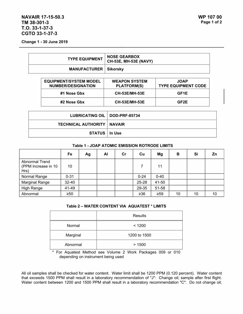
NAVAIR 17-15-50.3 TM 38-301-3 T.O. 33-1-37-3 CGTO 33-1-37-3
WP 107 00 Page 1 of 2
Change 1 - 30 June 2019
TYPE EQUIPMENT NOSE GEARBOX CH-53E, MH-53E (NAVY)
MANUFACTURER Sikorsky
EQUIPMENT/SYSTEM MODEL NUMBER/DESIGNATION
WEAPON SYSTEM PLATFORM(S)
JOAP TYPE EQUIPMENT CODE
#1 Nose Gbx CH-53E/MH-53E GF1E
#2 Nose Gbx CH-53E/MH-53E GF2E
LUBRICATING OIL DOD-PRF-85734
TECHNICAL AUTHORITY NAVAIR
STATUS In Use
Table 1 - JOAP ATOMIC EMISSION ROTRODE LIMITS
Fe Ag Al Cr Cu Mg B Si Zn
Abnormal Trend (PPM Increase in 10 Hrs)
10 7 11
Normal Range 0-31 0-24 0-40 Marginal Range 32-40 25-28 41-50 High Range 41-49 29-35 51-58 Abnormal ≥50 ≥36 ≥59 10 10 10
Table 2 – WATER CONTENT VIA AQUATEST * LIMITS
Results
Normal < 1200
Marginal 1200 to 1500
Abnormal > 1500
* For Aquatest Method see Volume 2 Work Packages 009 or 010 depending on instrument being used
All oil samples shall be checked for water content. Water limit shall be 1200 PPM (0.120 percent). Water content that exceeds 1500 PPM shall result in a laboratory recommendation of "J": Change oil; sample after first flight. Water content between 1200 and 1500 PPM shall result in a laboratory recommendation "C": Do not change oil;

NAVAIR 17-15-50.3 TM 38-301-3 T.O. 33-1-37-3 CGTO 33-1-37-3
WP 107 00 Page 2 of 2
Change 1 - 30 June 2019
resample after first flight. If resample results in water content still above 1200 PPM, laboratory recommendation shall be "J": Change oil; sample after first flight.
Water in the oil could cause high iron, copper, magnesium, or aluminum due to corrosion. If high or abnormal wear metals are obtained and high water is detected on two consecutive samples, the laboratory recommendations may be to drain gearbox, reservice and perform serviceability check. Info CFA when recommending flushing.
Elevated boron (B) and/or zinc (Zn) concentrations usually indicate contamination with another oil type, primarily MIL-PRF-2104. Recommend resampling and retesting immediately. If new value exceeds 8.0 PPM, run check with D19-0 to ensure proper instrument function. When proper function is confirmed, report both results and suspected contamination with MIL-PRF-2104 to chain of command, maintenance chief, cognizant engineering authority (Army and Navy only), and other personnel as specified by local written procedures. Recommend flushing and retesting of contaminated pre-oilers, carts, or other reservoirs where contamination is found until both B and Zn concentrations fall below 8.0 PPM. Refer to JOAP Manual Volume 2, WP 021 00 for more information. Recommend segregation of confirmed or suspected contaminated stocks, and submit information (batch no., lot no., MIL-PRF, nature of problem, etc.) on such stocks through the Defense supply deficiency reporting system.
Elevated silicon (Si) concentration usually indicates contamination with soil, sand, or dust. If aluminum (Al) is also elevated, this suggests the presence of clay or soil. Recommend resampling and retesting immediately. If new value exceeds 8.0 PPM, run check with D19-0 to ensure proper instrument function. When proper function is confirmed, report both results and suspected contamination with soil, sand, or dust to chain of command, maintenance chief, cognizant engineering authority (Army and Navy only), and other personnel as specified by local written procedures. Recommend flushing and retesting of contaminated pre-oilers, carts, or other reservoirs where contamination is found until silicon concentration falls below 8.0 PPM. Refer to JOAP Manual Volume 2, WP 021 00 for more information. Recommend segregation of confirmed or suspected contaminated stocks, and submit information (batch no., lot no., MIL-PRF, nature of problem, etc.) on such stocks through the Defense supply deficiency reporting system.
NOTES
Special samples may be recommended anytime unusual readings are obtained.
High metal readings without high water may result in a laboratory recommendation for flushing or removal of a gearbox. A minimum of two consecutive high readings is required prior to recommending flushing or removing gearbox unless other evidence (chiplights, fragments, unusual noise, etc.) is found. Info CFA when recommending flushing. CFA concurrence is required prior to a recommendation for gearbox removal due to high readings. Furnish CFA with 5 previous NOAP readings when recommending gearbox removal.

NAVAIR 17-15-50.3 TM 38-301-3 T.O. 33-1-37-3 CGTO 33-1-37-3
WP 108 00 Page 1 of 4
Change 1 - 30 June 2019
TYPE EQUIPMENT TAIL ROTOR GEARBOX CH-53E, MH-53E (NAVY)
MANUFACTURER Sikorsky
EQUIPMENT/SYSTEM MODEL NUMBER/DESIGNATION
WEAPON SYSTEM PLATFORM(S)
JOAP TYPE EQUIPMENT CODE
90/Tail Gbx CH-53E/MH-53E GFTE
LUBRICATING OIL DOD-PRF-85734
TECHNICAL AUTHORITY NAVAIR
STATUS In Use
Table 1 - JOAP ATOMIC EMISSION ROTRODE LIMITS
Fe Ag Al Cr Cu Mg Ti B Si Zn
Abnormal Trend (PPM Increase in 10 Hrs)
20 10 6 30
Normal Range 0-64 0-40 0-20 0-150 Marginal Range 65-76 41-50 21-25 151-200 High Range 77-99 51-58 26-30 201-249 Abnormal ≥100 ≥59 ≥31 ≥250 10 10 10
Table 2 – WATER CONTENT VIA AQUATEST * LIMITS
Results
Normal < 1200
Marginal 1200 to 1500
Abnormal > 1500
* For Aquatest Method see Volume 2 Work Packages 009 or 010 depending on instrument being used
All oil samples shall be checked for water content. Water limit shall be 1200 PPM (0.120 percent). Water content that exceeds 1500 PPM shall result in a laboratory recommendation of "J": Change oil; sample after first flight. Water content between 1200 and 1500 PPM shall result in a laboratory recommendation "C": Do not change oil;

NAVAIR 17-15-50.3 TM 38-301-3 T.O. 33-1-37-3 CGTO 33-1-37-3
WP 108 00 Page 2 of 4
Change 1 - 30 June 2019
resample after first flight. If resample results in water content still above 1200 PPM, laboratory recommendation shall be "J": Change oil; sample after first flight.
Water in the oil could cause high iron, copper, magnesium, or aluminum due to corrosion. If high or abnormal wear metals are obtained and high water is detected on two consecutive samples, the laboratory recommendations may be to drain gearbox, reservice and perform serviceability check. Info CFA when recommending flushing.
Common sources of titanium are the splines on the small shaft attached to the pitch change shaft and the wearing action of the pitch change shaft moving the tail rotor gearbox output shaft.
High readings of titanium are common and should not be of concern. An increase of titanium, copper, and iron should not be a matter of concern until the abnormal level of iron and titanium are exceeded. At this time the gearbox should be removed and replace.
Elevated boron (B) and/or zinc (Zn) concentrations usually indicate contamination with another oil type, primarily MIL-PRF-2104. Recommend resampling and retesting immediately. If new value exceeds 8.0 PPM, run check with D19-0 to ensure proper instrument function. When proper function is confirmed, report both results and suspected contamination with MIL-PRF-2104 to chain of command, maintenance chief, cognizant engineering authority (Army and Navy only), and other personnel as specified by local written procedures. Recommend flushing and retesting of contaminated pre-oilers, carts, or other reservoirs where contamination is found until both B and Zn concentrations fall below 8.0 PPM. Refer to JOAP Manual Volume 2, WP 021 00 for more information. Recommend segregation of confirmed or suspected contaminated stocks, and submit information (batch no., lot no., MIL-PRF, nature of problem, etc.) on such stocks through the Defense supply deficiency reporting system.
Elevated silicon (Si) concentration usually indicates contamination with soil, sand, or dust. If aluminum (Al) is also elevated, this suggests the presence of clay or soil. Recommend resampling and retesting immediately. If new value exceeds 8.0 PPM, run check with D19-0 to ensure proper instrument function. When proper function is confirmed, report both results and suspected contamination with soil, sand, or dust to chain of command, maintenance chief, cognizant engineering authority (Army and Navy only), and other personnel as specified by local written procedures. Recommend flushing and retesting of contaminated pre-oilers, carts, or other reservoirs where contamination is found until silicon concentration falls below 8.0 PPM. Refer to JOAP Manual Volume 2, WP 021 00 for more information. Recommend segregation of confirmed or suspected contaminated stocks, and submit information (batch no., lot no., MIL-PRF, nature of problem, etc.) on such stocks through the Defense supply deficiency reporting system.
NOTES
Special samples may be recommended anytime unusual readings are obtained.
High metal readings without high water may result in a laboratory recommendation for flushing or removal of a gearbox. A minimum of two consecutive high readings is required prior to recommending flushing or removing gearbox unless other evidence (chiplights, fragments, unusual noise, etc.) is found. Info CFA when recommending flushing. CFA concurrence is required prior to a recommendation for gearbox removal due to high readings. Furnish CFA with 5 previous NOAP readings when recommending gearbox removal.

NAVAIR 17-15-50.3 TM 38-301-3 T.O. 33-1-37-3 CGTO 33-1-37-3
WP 108 00 Page 3 of 4
Change 1 - 30 June 2019
NOTE
CFA concurrence for removal is not necessary when the increase in titanium is abnormal over three consecutive readings.
Ti A reading in excess of 150 PPM will require monitoring. Do not allow an oil change at this time. Remove the pitch change shaft when Ti reaches high range of 250 PPM. These high readings indicate wear to the inner shaft splines and to the output shaft.
Fe Ti Cu Increasing high readings of Fe, Ti, and Cu indicate excessive wear to the gearbox and pitch change shaft. When the Fe readings reach the abnormal level, remove gearbox and pitch change shaft. Do not allow an oil change during the period of increasing wear metal.

NAVAIR 17-15-50.3 TM 38-301-3 T.O. 33-1-37-3 CGTO 33-1-37-3
WP 108 00 Page 4 of 4
Change 1 - 30 June 2019
This Page Intentionally Left Blank
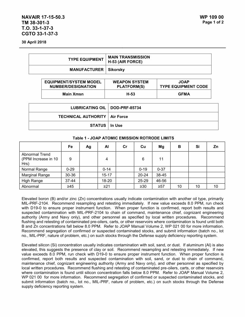
NAVAIR 17-15-50.3 TM 38-301-3 T.O. 33-1-37-3 CGTO 33-1-37-3
WP 109 00 Page 1 of 2
30 April 2018
TYPE EQUIPMENT MAIN TRANSMISSION H-53 (AIR FORCE)
MANUFACTURER Sikorsky
EQUIPMENT/SYSTEM MODEL NUMBER/DESIGNATION
WEAPON SYSTEM PLATFORM(S)
JOAP TYPE EQUIPMENT CODE
Main Xmsn H-53 GFMA
LUBRICATING OIL DOD-PRF-85734
TECHNICAL AUTHORITY Air Force
STATUS In Use
Table 1 - JOAP ATOMIC EMISSION ROTRODE LIMITS
Fe Ag Al Cr Cu Mg B Si Zn
Abnormal Trend (PPM Increase in 10 Hrs)
9 4 6 11
Normal Range 0-29 0-14 0-19 0-37 Marginal Range 30-36 15-17 20-24 38-45 High Range 37-44 18-20 25-29 46-56 Abnormal ≥45 ≥21 ≥30 ≥57 10 10 10
Elevated boron (B) and/or zinc (Zn) concentrations usually indicate contamination with another oil type, primarily MIL-PRF-2104. Recommend resampling and retesting immediately. If new value exceeds 8.0 PPM, run check with D19-0 to ensure proper instrument function. When proper function is confirmed, report both results and suspected contamination with MIL-PRF-2104 to chain of command, maintenance chief, cognizant engineering authority (Army and Navy only), and other personnel as specified by local written procedures. Recommend flushing and retesting of contaminated pre-oilers, carts, or other reservoirs where contamination is found until both B and Zn concentrations fall below 8.0 PPM. Refer to JOAP Manual Volume 2, WP 021 00 for more information. Recommend segregation of confirmed or suspected contaminated stocks, and submit information (batch no., lot no., MIL-PRF, nature of problem, etc.) on such stocks through the Defense supply deficiency reporting system.
Elevated silicon (Si) concentration usually indicates contamination with soil, sand, or dust. If aluminum (Al) is also elevated, this suggests the presence of clay or soil. Recommend resampling and retesting immediately. If new value exceeds 8.0 PPM, run check with D19-0 to ensure proper instrument function. When proper function is confirmed, report both results and suspected contamination with soil, sand, or dust to chain of command, maintenance chief, cognizant engineering authority (Army and Navy only), and other personnel as specified by local written procedures. Recommend flushing and retesting of contaminated pre-oilers, carts, or other reservoirs where contamination is found until silicon concentration falls below 8.0 PPM. Refer to JOAP Manual Volume 2, WP 021 00 for more information. Recommend segregation of confirmed or suspected contaminated stocks, and submit information (batch no., lot no., MIL-PRF, nature of problem, etc.) on such stocks through the Defense supply deficiency reporting system.

NAVAIR 17-15-50.3 TM 38-301-3 T.O. 33-1-37-3 CGTO 33-1-37-3
WP 109 00 Page 2 of 2
30 April 2018
This Page Intentionally Left Blank

NAVAIR 17-15-50.3 TM 38-301-3 T.O. 33-1-37-3 CGTO 33-1-37-3
WP 110 00 Page 1 of 2
30 April 2018
TYPE EQUIPMENT MAIN GEARBOX H-57 (NAVY)
MANUFACTURER Bell Helicopter Textron
EQUIPMENT/SYSTEM MODEL NUMBER/DESIGNATION
WEAPON SYSTEM PLATFORM(S)
JOAP TYPE EQUIPMENT CODE
Main Xmsn TH-57B GSMB
LUBRICATING OIL DOD-PRF-85734
TECHNICAL AUTHORITY NAVAIR
STATUS In Use
Table 1 - JOAP ATOMIC EMISSION ROTRODE LIMITS
Fe Ag Al Cr Cu Mg B Si Zn
Abnormal Trend (PPM Increase in 10 Hrs)
26 6 6 13
Normal Range 0-85 0-20 0-20 0-42 Marginal Range 86-105 21-25 21-25 43-52 High Range 106-129 26-30 26-30 53-64 Abnormal ≥130 ≥31 ≥31 ≥65 10 10 10
Elevated boron (B) and/or zinc (Zn) concentrations usually indicate contamination with another oil type, primarily MIL-PRF-2104. Recommend resampling and retesting immediately. If new value exceeds 8.0 PPM, run check with D19-0 to ensure proper instrument function. When proper function is confirmed, report both results and suspected contamination with MIL-PRF-2104 to chain of command, maintenance chief, cognizant engineering authority (Army and Navy only), and other personnel as specified by local written procedures. Recommend flushing and retesting of contaminated pre-oilers, carts, or other reservoirs where contamination is found until both B and Zn concentrations fall below 8.0 PPM. Refer to JOAP Manual Volume 2, WP 021 00 for more information. Recommend segregation of confirmed or suspected contaminated stocks, and submit information (batch no., lot no., MIL-PRF, nature of problem, etc.) on such stocks through the Defense supply deficiency reporting system.
Elevated silicon (Si) concentration usually indicates contamination with soil, sand, or dust. If aluminum (Al) is also elevated, this suggests the presence of clay or soil. Recommend resampling and retesting immediately. If new value exceeds 8.0 PPM, run check with D19-0 to ensure proper instrument function. When proper function is confirmed, report both results and suspected contamination with soil, sand, or dust to chain of command, maintenance chief, cognizant engineering authority (Army and Navy only), and other personnel as specified by local written procedures. Recommend flushing and retesting of contaminated pre-oilers, carts, or other reservoirs where contamination is found until silicon concentration falls below 8.0 PPM. Refer to JOAP Manual Volume 2, WP 021 00 for more information. Recommend segregation of confirmed or suspected contaminated stocks, and submit information (batch no., lot no., MIL-PRF, nature of problem, etc.) on such stocks through the Defense supply deficiency reporting system.

NAVAIR 17-15-50.3 TM 38-301-3 T.O. 33-1-37-3 CGTO 33-1-37-3
WP 110 00 Page 2 of 2
30 April 2018
This Page Intentionally Left Blank

NAVAIR 17-15-50.3 TM 38-301-3 T.O. 33-1-37-3 CGTO 33-1-37-3
WP 111 00 Page 1 of 2
30 April 2018
TYPE EQUIPMENT TAIL ROTOR GEARBOX H-57 (NAVY)
MANUFACTURER Bell Helicopter Textron
EQUIPMENT/SYSTEM MODEL NUMBER/DESIGNATION
WEAPON SYSTEM PLATFORM(S)
JOAP TYPE EQUIPMENT CODE
90/Tail Gbx TH-57B GSTB
LUBRICATING OIL DOD-PRF-85734
TECHNICAL AUTHORITY NAVAIR
STATUS In Use
Table 1 - JOAP ATOMIC EMISSION ROTRODE LIMITS
Fe Ag Al Cr Cu Mg B Si Zn
Abnormal Trend (PPM Increase in 10 Hrs)
23 6 13
Normal Range 0-76 0-20 0-42 Marginal Range 77-92 21-25 43-52 High Range 93-114 26-30 53-64 Abnormal ≥115 ≥31+ ≥65 10 10 10
Elevated boron (B) and/or zinc (Zn) concentrations usually indicate contamination with another oil type, primarily MIL-PRF-2104. Recommend resampling and retesting immediately. If new value exceeds 8.0 PPM, run check with D19-0 to ensure proper instrument function. When proper function is confirmed, report both results and suspected contamination with MIL-PRF-2104 to chain of command, maintenance chief, cognizant engineering authority (Army and Navy only), and other personnel as specified by local written procedures. Recommend flushing and retesting of contaminated pre-oilers, carts, or other reservoirs where contamination is found until both B and Zn concentrations fall below 8.0 PPM. Refer to JOAP Manual Volume 2, WP 021 00 for more information. Recommend segregation of confirmed or suspected contaminated stocks, and submit information (batch no., lot no., MIL-PRF, nature of problem, etc.) on such stocks through the Defense supply deficiency reporting system.
Elevated silicon (Si) concentration usually indicates contamination with soil, sand, or dust. If aluminum (Al) is also elevated, this suggests the presence of clay or soil. Recommend resampling and retesting immediately. If new value exceeds 8.0 PPM, run check with D19-0 to ensure proper instrument function. When proper function is confirmed, report both results and suspected contamination with soil, sand, or dust to chain of command, maintenance chief, cognizant engineering authority (Army and Navy only), and other personnel as specified by local written procedures. Recommend flushing and retesting of contaminated pre-oilers, carts, or other reservoirs where contamination is found until silicon concentration falls below 8.0 PPM. Refer to JOAP Manual Volume 2, WP 021 00 for more information. Recommend segregation of confirmed or suspected contaminated stocks, and submit information (batch no., lot no., MIL-PRF, nature of problem, etc.) on such stocks through the Defense supply deficiency reporting system.

NAVAIR 17-15-50.3 TM 38-301-3 T.O. 33-1-37-3 CGTO 33-1-37-3
WP 111 00 Page 2 of 2
30 April 2018
This Page Intentionally Left Blank

NAVAIR 17-15-50.3 TM 38-301-3 T.O. 33-1-37-3 CGTO 33-1-37-3
WP 112 00 Page 1 of 2
30 April 2018
TYPE EQUIPMENT MAIN TRANSMISSION OH-58A/C (ARMY)
MANUFACTURER Bell Helicopter
EQUIPMENT/SYSTEM MODEL NUMBER/DESIGNATION
WEAPON SYSTEM PLATFORM(S)
JOAP TYPE EQUIPMENT CODE
Main Xmsn OH-58A GKMA
Main Xmsn OH-58C GKMC
LUBRICATING OIL MIL-PRF-23699, MIL-PRF-7808 or DOD-PRF-85734
TECHNICAL AUTHORITY Army Aviation Command
STATUS In Use
Table 1 - JOAP ATOMIC EMISSION ROTRODE LIMITS
Fe Ag Al Cr Cu Mg Mo B Si Zn
Abnormal Trend (PPM Increase in 10 Hrs)
4 2 4 3 3 4 8
Normal Range 0-15 0-3 0-13 0-6 0-8 0-12 0-26 Marginal Range 16-18 N/A 14-16 7 9-10 13-15 27-32 High Range 19-23 4 17-19 8-9 11-12 16-17 33-39 Abnormal ≥24 ≥5 ≥20 ≥10 ≥13 ≥18 10 ≥40 10
Fe Main drive oil pump gearing Bearing load surfaces
Fe & Cu Bearing assemblies
Fe & Al Upper case and ring gear, oil pump assembly Lower mast bearing and support plate
Fe Al & Cu Planetary bearing assemblies
Fe & Mg Transmission lower case

NAVAIR 17-15-50.3 TM 38-301-3 T.O. 33-1-37-3 CGTO 33-1-37-3
WP 112 00 Page 2 of 2
30 April 2018
Elevated boron (B) and/or zinc (Zn) concentrations usually indicate contamination with another oil type, primarily MIL-PRF-2104. Recommend resampling and retesting immediately. If new value exceeds 8.0 PPM, run check with D19-0 to ensure proper instrument function. When proper function is confirmed, report both results and suspected contamination with MIL-PRF-2104 to chain of command, maintenance chief, cognizant engineering authority (Army and Navy only), and other personnel as specified by local written procedures. Recommend flushing and retesting of contaminated pre-oilers, carts, or other reservoirs where contamination is found until both B and Zn concentrations fall below 8.0 PPM. Refer to JOAP Manual Volume 2, WP 021 00 for more information. Recommend segregation of confirmed or suspected contaminated stocks, and submit information (batch no., lot no., MIL-PRF, nature of problem, etc.) on such stocks through the Defense supply deficiency reporting system.
NOTE
High concentration of Fe and Mg indicates possible corrosion in the transmission lower case and metal concentration will probably increase after extended periods of inactivity.

NAVAIR 17-15-50.3 TM 38-301-3 T.O. 33-1-37-3 CGTO 33-1-37-3
WP 113 00 Page 1 of 2
30 April 2018
TYPE EQUIPMENT 90° TAIL ROTOR GEARBOX OH-58A/C (ARMY)
MANUFACTURER Bell Helicopter
EQUIPMENT/SYSTEM MODEL NUMBER/DESIGNATION
WEAPON SYSTEM PLATFORM(S)
JOAP TYPE EQUIPMENT CODE
90/Tail Gbx OH-58A GKTA
90/Tail Gbx OH-58C GKTC
LUBRICATING OIL MIL-PRF-23699, MIL-PRF-7808 or DOD-PRF-85734
TECHNICAL AUTHORITY Army Aviation Command
STATUS In Use
Table 1 - JOAP ATOMIC EMISSION ROTRODE LIMITS
Fe Ag Al Cr Cu Mg Mo B Si Zn
Abnormal Trend (PPM Increase in 10 Hrs)
15 2 4 4 4 8 26
Normal Range 0-50 0-5 0-11 0-14 0-14 0-27 0-86 Marginal Range 51-62 6 12-13 15-17 15-17 28-33 87-106 High Range 63-76 7 14-16 18-21 18-22 34-41 107-131 Abnormal ≥77 ≥8 ≥17 ≥22 ≥23 ≥42 10 ≥132 10
Fe Bevel gears Bearing load surfaces and gearlock seal spring on shaft
Fe Cu & Ag Bearing gears and bearing assemblies
Fe & Al Bearing liner in quill plate
Fe & Mg Gearing and Case
Elevated boron (B) and/or zinc (Zn) concentrations usually indicate contamination with another oil type, primarily MIL-PRF-2104. Recommend resampling and retesting immediately. If new value exceeds 8.0 PPM, run check with D19-0 to ensure proper instrument function. When proper function is confirmed, report both results and suspected contamination with MIL-PRF-2104 to chain of command, maintenance chief, cognizant engineering authority (Army and Navy only), and other personnel as specified by local written procedures. Recommend flushing and retesting of contaminated pre-oilers, carts, or other reservoirs where contamination is found until both

NAVAIR 17-15-50.3 TM 38-301-3 T.O. 33-1-37-3 CGTO 33-1-37-3
WP 113 00 Page 2 of 2
30 April 2018
B and Zn concentrations fall below 8.0 PPM. Refer to JOAP Manual Volume 2, WP 021 00 for more information. Recommend segregation of confirmed or suspected contaminated stocks, and submit information (batch no., lot no., MIL-PRF, nature of problem, etc.) on such stocks through the Defense supply deficiency reporting system.
NOTES
1. Tail rotor or drive line vibration may induce temporary high level of Fe, Cu & Al.
2. High Fe & Mg indicate possible corrosion in the gearing and case. Concentration will probably increase after extended periods of inactivity.
3. Inspect the aluminum wool in the oil filter cap for deterioration when excessive aluminum wear metal is detected in oil samples from OH-58 90˚ gearbox.

NAVAIR 17-15-50.3 TM 38-301-3 T.O. 33-1-37-3 CGTO 33-1-37-3
WP 114 00 Page 1 of 2
30 April 2018
TYPE EQUIPMENT H-60A MAIN TRANSMISSION (ARMY)
MANUFACTURER Sikorsky
EQUIPMENT/SYSTEM MODEL NUMBER/DESIGNATION
WEAPON SYSTEM PLATFORM(S)
JOAP TYPE EQUIPMENT CODE
MainXmsn UH-60A GLMK
MainXmsn(3µ) UH-60A GLMA
MainXmsn EH-60A GLMM
MainXmsn(3µ) EH-60A GLMC
MainXmsn HH-60A GLMP
MAIN XMSN-3µ HH-60A GLMS
LUBRICATING OIL MIL-PRF-7808, MIL-PRF-23699 or DOD-PRF-85734
TECHNICAL AUTHORITY US Army Aviation Command
STATUS In Use
Table 1 - JOAP ATOMIC EMISSION ROTRODE LIMITS
Fe Ag Al Cr Cu Mg Mo B Si Zn
Abnormal Trend (PPM Increase in 10 Hrs)
7 2 2 4 4 2 4
Normal Range 0-25 0-2 0-2 0-10 0-13 0-2 0-13 Marginal Range 26-31 3 3 11-12 14-16 3 14-16 High Range 32-37 4 4 13-14 17-19 4 17-19 Abnormal ≥38 ≥5 ≥5 ≥15 ≥20 ≥5 ≥20
Table 2 – WATER CONTENT VIA AQUATEST * LIMITS Normal < 1200
Abnormal ≥ 1200 * For Aquatest Method see Volume 2 Work Packages 009 or 010 depending on instrument being used

NAVAIR 17-15-50.3 TM 38-301-3 T.O. 33-1-37-3 CGTO 33-1-37-3
WP 114 00 Page 2 of 2
30 April 2018
NOTES
Ag - Silver has been used in plating some splines and gears. When values greater than 5 PPM are observed, a serviceability check should be requested. Instructions for transmissions serviceability check are provided in TM 55-1520-237-23-7.
Cr/Mo - Chromium and molybdenum should not be considered critical metals unless iron is present in abnormal concentrations.
Mg/Al - Magnesium and aluminum are usually observed wherever corrosion exists. However, when iron, magnesium, and aluminum are present in abnormal concentrations, microscopic inspection of debris should be performed to determine whether metal is due to wear or corrosion.
Si - The probable sources of silicon are contamination and anti-foaming agents in lubricants. When the source of silicon is contamination, the component should be drained, flushed, serviced with new oil, and sampled after 5 hours of operation to assure removal of abrasive contaminants.
Elevated boron (B) and/or zinc (Zn) concentrations usually indicate contamination with another oil type, primarily MIL-PRF-2104. Recommend resampling and retesting immediately. If new value exceeds 8.0 PPM, run check with D19-0 to ensure proper instrument function. When proper function is confirmed, report both results and suspected contamination with MIL-PRF-2104 to chain of command, maintenance chief, cognizant engineering authority (Army and Navy only), and other personnel as specified by local written procedures. Recommend flushing and retesting of contaminated pre-oilers, carts, or other reservoirs where contamination is found until both B and Zn concentrations fall below 8.0 PPM. Refer to JOAP Manual Volume 2, WP 021 00 for more information. Recommend segregation of confirmed or suspected contaminated stocks, and submit information (batch no., lot no., MIL-PRF, nature of problem, etc.) on such stocks through the Defense supply deficiency reporting system.
NOTE
Wear particles found in an oil sample will give a false indication. Oil samples are taken from the sump, which is on the upstream side of the filter. When the rotors stop turning, the oil slowly drains and flushes the debris trapped by the filter into the sump.
The main transmission consists of a main module, two input modules and two accessory modules. The main transmission has a single lubrication system that lubricates the modules listed above as well as the gearbox driven generators. For the UH-60A, EH-60A, HH-60A, aircraft, spectrometric analysis is required. Oil physical properties should also be checked for the following: water content, viscosity (40 C & 100 C), total acid number (TAN), particle count (cleanliness). For these U.S. Army aircraft, main transmission water content limit shall be 1200 PPM (0.120%). For all configurations of main transmissions, water content that exceeds 1500 PPM shall result in a laboratory recommendation “J”: change oil; sample after first flight. Water content between 1200 and 1500 PPM shall result in a laboratory recommendation “C”: do not change oil; resample after first flight. If resample results in water content still above 1200 PPM, laboratory recommendation shall be “J”: change oil; sample after first flight. If a condition exists which is not covered by the information below contact the Aviation Engineering Directorate, Utility Division (RDMR-AEU): [email protected].

NAVAIR 17-15-50.3 TM 38-301-3 T.O. 33-1-37-3 CGTO 33-1-37-3
WP 115 00 Page 1 of 2
30 April 2018
TYPE EQUIPMENT H-60L/M/K MAIN TRANSMISSION (3 MICRON FILTER)
MANUFACTURER Sikorsky
EQUIPMENT/SYSTEM MODEL NUMBER/DESIGNATION
WEAPON SYSTEM PLATFORM(S)
JOAP TYPE EQUIPMENT CODE
MainXmsn EH-60L GLML
MainXmsn UH-60L GLMD
MainXmsn UH-60M GLMQ
MainXmsn HH-60L GLMI
MainXmsn MH-60L GLMG
MainXmsn MH-60K N/A
MainXmsn MH-60M GLMR
LUBRICATING OIL DOD-PRF-85734 (Alternative oil: MIL-PRF-23699 or MIL-PRF-7808)
TECHNICAL AUTHORITYS US Army Aviation Command
Table 1 – WATER CONTENT VIA AQUATEST * LIMITS
Results
Normal < 1200
Marginal 1200 to 1500
Abnormal > 1500
* For Aquatest Method see Volume 2 Work Packages 009 or 010 depending on instrument being used

NAVAIR 17-15-50.3 TM 38-301-3 T.O. 33-1-37-3 CGTO 33-1-37-3
WP 115 00 Page 2 of 2
30 April 2018
NOTE
Wear particles found in an oil sample will give a false indication. Oil samples are taken from the sump, which is on the upstream side of the 3-micron filter. When the rotors stop turning, the oil slowly drains and flushes the debris trapped by the filter into the sump.
The main transmission consists of a main module, two input modules and two accessory modules. The main transmission has a single lubrication system that lubricates the modules listed above as well as the gearbox driven generators. For the UH-60L, UH-60M, EH-60L, HH-60L, MH-60L, MH-60K, and MH-60M aircraft, a 3-micron filter is used which effectively removes particles in the size range measurable by spectrometric analysis. Oil physical properties should be checked for the following: water content, viscosity (40 C & 100 C), total acid number (TAN), and particle count (cleanliness). For these U.S. Army aircraft, main transmission water content limit shall be 1200 PPM (0.120%). For all configurations of main transmissions, water content that exceeds 1500 PPM shall result in a laboratory recommendation “J”: change oil; sample after first flight. Water content between 1200 and 1500 PPM shall result in a laboratory recommendation “C”: do not change oil; resample after first flight. If resample results in water content still above 1200 PPM, laboratory recommendation shall be “J”: change oil; sample after first flight. If a condition exists which is not covered by the information below contact the Aviation Engineering Directorate, Utility Division (RDMR-AEU): [email protected].
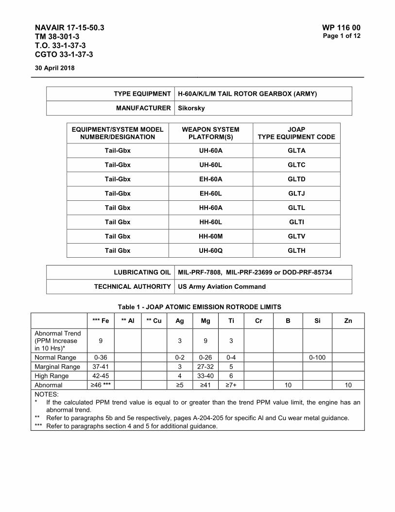
NAVAIR 17-15-50.3 TM 38-301-3 T.O. 33-1-37-3 CGTO 33-1-37-3
WP 116 00 Page 1 of 12
30 April 2018
TYPE EQUIPMENT H-60A/K/L/M TAIL ROTOR GEARBOX (ARMY)
MANUFACTURER Sikorsky
EQUIPMENT/SYSTEM MODEL NUMBER/DESIGNATION
WEAPON SYSTEM PLATFORM(S)
JOAP TYPE EQUIPMENT CODE
Tail-Gbx UH-60A GLTA
Tail-Gbx UH-60L GLTC
Tail-Gbx EH-60A GLTD
Tail-Gbx EH-60L GLTJ
Tail Gbx HH-60A GLTL
Tail Gbx HH-60L GLTI
Tail Gbx HH-60M GLTV
Tail Gbx UH-60Q GLTH
LUBRICATING OIL MIL-PRF-7808, MIL-PRF-23699 or DOD-PRF-85734
TECHNICAL AUTHORITY US Army Aviation Command
Table 1 - JOAP ATOMIC EMISSION ROTRODE LIMITS
*** Fe ** Al ** Cu Ag Mg Ti Cr B Si Zn
Abnormal Trend (PPM Increase in 10 Hrs)*
9 3 9 3
Normal Range 0-36 0-2 0-26 0-4 0-100 Marginal Range 37-41 3 27-32 5 High Range 42-45 4 33-40 6 Abnormal ≥46 *** ≥5 ≥41 ≥7+ 10 10 NOTES: * If the calculated PPM trend value is equal to or greater than the trend PPM value limit, the engine has an
abnormal trend. ** Refer to paragraphs 5b and 5e respectively, pages A-204-205 for specific Al and Cu wear metal guidance. *** Refer to paragraphs section 4 and 5 for additional guidance.

NAVAIR 17-15-50.3 TM 38-301-3 T.O. 33-1-37-3 CGTO 33-1-37-3
WP 116 00 Page 2 of 12
30 April 2018
Table 2 – WATER CONTENT VIA AQUATEST * LIMITS
Normal < 1200 Abnormal ≥ 1200
* For Aquatest Method see Volume 2 Work Packages 009 or 010 depending on instrument being used
For the UH-60L, UH-60M, EH-60L, HH-60L, MH-60L, MH-60K, and MH-60M tail rotor gearbox, spectrometric analysis is required. Oil physical properties should also be checked for the following: water content, viscosity (40 C & 100 C), total acid number (TAN), and particle count (cleanliness).
Additional guidance specific to the Army H-60 Black Hawk helicopter is located on page A-210.
Elevated boron (B) and/or zinc (Zn) concentrations usually indicate contamination with another oil type, primarily MIL-PRF-2104. Recommend resampling and retesting immediately. If new value exceeds 8.0 PPM, run check with D19-0 to ensure proper instrument function. When proper function is confirmed, report both results and suspected contamination with MIL-PRF-2104 to chain of command, maintenance chief, cognizant engineering authority (Army and Navy only), and other personnel as specified by local written procedures. Recommend flushing and retesting of contaminated pre-oilers, carts, or other reservoirs where contamination is found until both B and Zn concentrations fall below 8.0 PPM. Refer to JOAP Manual Volume 2, WP 021 00 for more information. Recommend segregation of confirmed or suspected contaminated stocks, and submit information (batch no., lot no., MIL-PRF, nature of problem, etc.) on such stocks through the Defense supply deficiency reporting system.
Elevated silicon (Si) concentration usually indicates contamination with soil, sand, or dust. If aluminum (Al) is also elevated, this suggests the presence of clay or soil. Recommend re-sampling and retesting immediately. If new value exceeds 8.0 PPM, run check with D19-0 to ensure proper instrument function. When proper function is confirmed, report both results and suspected contamination with soil, sand, or dust to chain of command, maintenance chief, cognizant engineering authority (Army and Navy only), and other personnel as specified by local written procedures. Recommend flushing and retesting of contaminated pre-oilers, carts, or other reservoirs where contamination is found until silicon concentration falls below 8.0 PPM. Refer to JOAP Manual Volume 2, WP 021 00 for more information. Recommend segregation of confirmed or suspected contaminated stocks, and submit information (batch no., lot no., MIL-PRF, nature of problem, etc.) on such stocks through the Defense supply deficiency reporting system. The following information is provided to assist oil analysis laboratory personnel in determining tail rotor gearbox condition based upon an analysis of the gearbox lubricant. The following information does not cover every possible wear mode or operational characteristic. The information is intended to assist the lab personnel in making a determination of the health of the gearbox. If a situation exists that is not covered by the following information, or if additional information or clarification of existing information is desired, contact AMCOM Engineering, AMSRD-AMR-AE-P-M, DSN: 897-9103.
1. The BLACK HAWK tail rotor gearbox changes the speed and angle of drive from the tail drive shaft to the tail rotor blades and pitch control mechanism. See Figure 1. The major components of the tail rotor gearbox include the housings (input, center, and output), the input bevel pinion and the output bevel gear, four (4) tapered roller bearings, an input flange, an inboard retention plate, and input and output seals. See Figure 2 for the location of the major components. The tail rotor gearbox is operated with the tail rotor servo and pitch control shaft installed into the gearbox. See Figure 3.

NAVAIR 17-15-50.3 TM 38-301-3 T.O. 33-1-37-3 CGTO 33-1-37-3
WP 116 00 Page 3 of 12
30 April 2018
2. The tail rotor gearbox utilized a self-contained splash-type lube system without an oil filter. Normal wear particles will increase in number until the gearbox is drained and flushed. Either DOD-L-85734, MIL-L-23699, or MIL-L-7808 lubricant is used in the gearbox. The gearbox contains approximately 2.75 pints of lubricant. The gearbox lubricant is replaced every 720 flight hours.
a. MIL-L-23699 is the most common lubricant in use in the field. It is being replaced by the DOD-L-85734 lubricant, which is now the primary lubricant. DOD-L-85734 lubricant is similar to MIL-L-23699 (e.g., it has the same viscosity), but has the addition of EP (Extreme Pressure) additives to improve its performance with loaded gear meshes. Field units should notify the lab if a change to DOD-L-85734 lubricant is in order to establish a baseline for this lubricant. Establishment of a baseline is essential in analyzing tail rotor gearboxes using the DOD-L-85734 lubricant. MIL-L-7808 lubricant will continue to be used for cold-weather operation.
b. When used in gearboxes which had been operated with MIL-L-23699 or MIL-L-7808 lubricant, the DOD-L-85734 lubricant has a detergent effect. This may cause an increase in wear metal levels as seen in spectrometric analysis of oil samples. Lab personnel should use caution when analyzing oil samples in these cases, as the increase in wear metal levels may give the same indications that component wear would give. After gearboxes which have changed to DOD-L-85734 have operated for 50 - 100 flight hours, have the unit perform a drain and flush to remove wear metals from the gearbox.
c. Oil analysis laboratory personnel should not hesitate to request a drain and flush of the tail rotor gearbox if they believe it is warranted. Removal of contaminants and wear particles from the gearbox lubricant is the best method to prolong gearbox life and prevent future problems. Drain and flush procedures are given in paragraph 7 below.

NAVAIR 17-15-50.3 TM 38-301-3 T.O. 33-1-37-3 CGTO 33-1-37-3
WP 116 00 Page 4 of 12
30 April 2018
3. Oil analysis lab personnel may receive oil samples either from a regular interval sampling, or whenever the field unit experiences a problem with the tail rotor gearbox on their aircraft. The regular sampling interval is 40 flight hours. The most common cause for field units to send a special sample to the oil analysis laboratory is when there are chips present in the gearbox. Table 3 gives the chip evaluation criteria for tail rotor gearboxes. These criteria may be used by laboratory personnel to assist in the evaluation of the condition of a tail rotor gearbox from which chips were identified.
FIGURE 1. Tail Rotor Gearbox
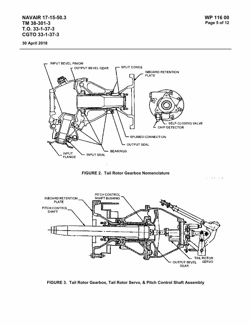
NAVAIR 17-15-50.3 TM 38-301-3 T.O. 33-1-37-3 CGTO 33-1-37-3
WP 116 00 Page 5 of 12
30 April 2018
FIGURE 2. Tail Rotor Gearbox Nomenclature
FIGURE 3. Tail Rotor Gearbox, Tail Rotor Servo, & Pitch Control Shaft Assembly

NAVAIR 17-15-50.3 TM 38-301-3 T.O. 33-1-37-3 CGTO 33-1-37-3
WP 116 00 Page 6 of 12
30 April 2018
TABLE 3. Chip Evaluation Criteria
MATERIAL TYPE - QUANTITY - SIZE ACTION REQUIRED
Magnetic (Steel) Particles too small to measure None
Less than 10 particles, none over 1/32" diameter and 1/4" long.
Perform a serviceability check IAW applicable aircraft maintenance manual.
Splinters or granular particles.
Perform a serviceability check IAW applicable aircraft maintenance manual.
Chips exceeding the size and/or number criteria above.
Replace tail rotor gearbox.
Non-Magnetic All particle sizes. Perform a serviceability check IAW applicable aircraft maintenance manual.
4. All oil samples submitted for analysis should be checked for water contamination. The limit is 1200 PPM or 0.120%. Gearboxes with water contamination should be drained and flushed per paragraph 7 below in an attempt to prevent gearbox housing corrosion. See paragraph 6b for further information.
5. Sources of wear metal elements in oil samples are given in Table 5.
a. Iron (Fe). Iron wear particles may indicate wear of the gears, bearings, bearing liners, or pitch control shaft. For further information on iron wear metal, see paragraph 6a below.
b. Aluminum (Al). Aluminum wear particles may indicate wear of the inboard retention split cones (copper would also be present), or corrosion of the input pinion plug. Aluminum is not used as a primary means of detecting component wear. If titanium is normal, no action is required.
c. Titanium (Ti). Titanium wear particles may indicate wear of the inboard retention plate splines or the input flange splines. Wear of the inboard retention plate splines would also result in high aluminum and copper wear metal levels. Wear of the input flange splines would also result in high aluminum wear metal levels. Performance of torque checks on the nuts/bolts connecting the input flange/inboard retention plate to the gearbox is used to determine if wear of these splines is present. See also paragraph 6c and 6d below.
d. Magnesium (Mg). Magnesium wear particles usually indicate that corrosion of the gearbox housing(s) is present. The most common location of gearbox corrosion is the tail rotor servo bore area. See also paragraph 6b below.
NOTES
The unit will submit a baseline sample 9 – 13 hours after installation of new oilite bushing.
The oil may not have been changed when the pitch change shaft with the oilite bushing was installed in the tail rotor gearbox.

NAVAIR 17-15-50.3 TM 38-301-3 T.O. 33-1-37-3 CGTO 33-1-37-3
WP 116 00 Page 7 of 12
30 April 2018
e. Copper (Cu). Copper is not a critical wear metal in the H-60 tail rotor gearbox. Copper usually indicates wear on the pitch change shaft oilite bronze bushing from sliding contact with the inner diameter of the steel output bevel gear. Iron from the bevel gear will often accompany copper. Wear on the oilite bushing is common and is the subject of dimensional inspection during scheduled removals. Wear is typically greater in the first 100 – 200 flight hours on a new bushing installation. Wear is the greatest with a new bushing in a 70358-26600-044 tail rotor gearbox. (The –044 gearbox contains the output bevel gear with shotpeened inner diameter, which has a rougher surface finish, thereby causing greater abrasion on the oilite bushing.)
Because wear is common and regular scheduled inspections gage wear on the oilite bushing, limited maintenance action is recommended for copper or copper/iron contamination in the first 100 hours of service on a new bushing. The only exception to this is if copper levels exceed 200 PPM and/or copper is accompanied by other critical wear metals. (See Table 4 for applicable maintenance actions and other critical wear metal criteria.) Between 100 – 200 flight hours, maintenance actions should be limited to oil change if the copper level exceeds 100 PPM, provided other critical wear metals are not involved. After 200 flight hours, a dimensional inspection of the bushing should be performed only when copper levels exceed 75 PPM for two consecutive monitoring intervals. Other sources of copper in the tail rotor gearbox are the aluminum bronze split cones on the inboard retention plate and the cage material on the duplex ball bearing in the tail rotor servo coupling. Split cones can contribute copper and aluminum to the oil if wear/fretting occurs. (See supplementary information for aluminum.) The duplex ball bearing is inside the pitch change shaft and is not normally exposed to oil flow.
TABLE 4. Excessive Copper Wear
Hours (since new bushing) Cu (PPM) ACTION
100 200 No maintenance required
100 200 Drain, refill. Sample @ 25 hours
100 & 200 100 No maintenance required
100 & 200 100 Drain, refill @ 200 hrs since new bushing
200 75 No maintenance required
200 75 * Perform dimensional inspection of bushing
NOTE: * For two consecutive sampling periods.
f. Silver (Ag). Silver is used as plating on the input pinion and output gear splines. Presence of silver wear particles usually indicates spline wear is occurring. Performance of torque checks on the nuts/bolts connecting the input flange/inboard retention plate to the gearbox is used to determine if wear of these splines is present. See also paragraphs 6c and 6d below.
g. Chromium (Cr). Chromium is present in some steels, and as a plating on the input/output seal wear sleeves. The presence of chromium wear particles may indicate wear of the seal sleeves, which would be detected through excessive seal leakage.
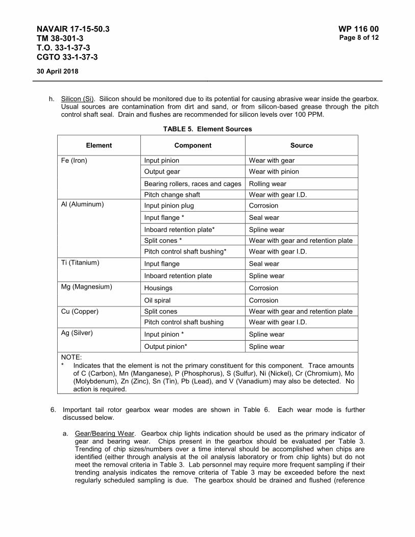
NAVAIR 17-15-50.3 TM 38-301-3 T.O. 33-1-37-3 CGTO 33-1-37-3
WP 116 00 Page 8 of 12
30 April 2018
h. Silicon (Si). Silicon should be monitored due to its potential for causing abrasive wear inside the gearbox. Usual sources are contamination from dirt and sand, or from silicon-based grease through the pitch control shaft seal. Drain and flushes are recommended for silicon levels over 100 PPM.
TABLE 5. Element Sources
Element Component Source
Fe (Iron) Input pinion Wear with gear Output gear Wear with pinion
Bearing rollers, races and cages Rolling wear Pitch change shaft Wear with gear I.D.
Al (Aluminum) Input pinion plug Corrosion
Input flange * Seal wear
Inboard retention plate* Spline wear Split cones * Wear with gear and retention plate Pitch control shaft bushing* Wear with gear I.D.
Ti (Titanium) Input flange Seal wear
Inboard retention plate Spline wear Mg (Magnesium) Housings Corrosion
Oil spiral Corrosion Cu (Copper) Split cones Wear with gear and retention plate
Pitch control shaft bushing Wear with gear I.D. Ag (Silver) Input pinion * Spline wear
Output pinion* Spline wear NOTE: * Indicates that the element is not the primary constituent for this component. Trace amounts
of C (Carbon), Mn (Manganese), P (Phosphorus), S (Sulfur), Ni (Nickel), Cr (Chromium), Mo (Molybdenum), Zn (Zinc), Sn (Tin), Pb (Lead), and V (Vanadium) may also be detected. No action is required.
6. Important tail rotor gearbox wear modes are shown in Table 6. Each wear mode is further discussed below.
a. Gear/Bearing Wear. Gearbox chip lights indication should be used as the primary indicator of gear and bearing wear. Chips present in the gearbox should be evaluated per Table 3. Trending of chip sizes/numbers over a time interval should be accomplished when chips are identified (either through analysis at the oil analysis laboratory or from chip lights) but do not meet the removal criteria in Table 3. Lab personnel may require more frequent sampling if their trending analysis indicates the remove criteria of Table 3 may be exceeded before the next regularly scheduled sampling is due. The gearbox should be drained and flushed (reference

NAVAIR 17-15-50.3 TM 38-301-3 T.O. 33-1-37-3 CGTO 33-1-37-3
WP 116 00 Page 9 of 12
30 April 2018
paragraph 7) as needed to remove any particles that may cause further wear if allowed to remain inside the gearbox. Indications of iron wear metal in spectrometric analysis samples without accompanying chip lights, Ferrographic, or microscopic indications shall be tracked but shall not be cause for recommendations for removal/replacement of the gearbox.
TABLE 6. Wear Modes and Diagnostic Methods
Wear Mode Diagnostic Method Criteria
Gear Wear Chip lights -or-Ferrographic/microscopic.
Table 3. Chip size/count.
Bearing Wear Chip lights -or-Ferrographic/microscopic.
Table 3. Chip size/count.
Housing Corrosion Spectrometric. Magnesium PPM level.
Inboard Retention Plate Output Gear Spline Wear
Spectrometric -and- Inboard retention plate nut bolt torque check (per TM55-1520-237-23)
Titanium and Aluminum PPM levels. Failure to stabilize torque (per TM55-1520-237-23)
Split Cone Wear Spectrometric -and- Inboard retention plate nut Bolt torque check (per TM55-1520-237-23)
Copper and Aluminum PPM levels. Failure to stabilize torque (perTM55-1520-237-23)
Pitch Control Shaft Bushing Wear
Inspection (Phase, per TM55-1520-237-PMS-2)
Bushing OD (per TM55-1520-237-PMS-2)
b. Housing Corrosion. Housing corrosion is identified by an increase in magnesium wear metal levels in spectrometric analysis results. At the first instance of an upward trend in magnesium levels, recommend the unit drain and flush the tail rotor gearbox (reference paragraph 7) to insure any water contamination is removed. If magnesium wear metal levels increase past the high range, recommend the unit remove the tail rotor servo and inspect the servo bore area and the gearbox ID for signs of corrosion. If corrosion is found it should be repaired per TM55-1520-237-23. If the corrosion cannot be repaired in the field, the gearbox should be replaced. If corrosion cannot be identified, and magnesium wear metal levels continue to increase into the abnormal range, the gearbox should be removed. Lab personnel may require more frequent sampling if a trending analysis indicates the magnesium wear metal level may exceed the abnormal range before the next regularly scheduled sampling is due.

NAVAIR 17-15-50.3 TM 38-301-3 T.O. 33-1-37-3 CGTO 33-1-37-3
WP 116 00 Page 10 of 12
30 April 2018
c. Inboard Retention Plate/Output Gear Spline Wear. Wear of the inboard intention plate/output gear splines is characterized by an increase in the levels of Ti (titanium), Al (aluminum), and Ag (silver) wear metals. An increase in aluminum wear metal levels alone, without an accompanying rise in titanium wear metal levels, does not explicitly indicate spline wear. Titanium and/or aluminum levels may be in the marginal/high range on new gearboxes (less than 100 flight hours since new/overhauled) due to normal break-in wear of the internal components. If spline wear is suspected (titanium in the high/abnormal range), recommend that the unit perform an inboard retention plate nut bolt torque check, and report their findings (bolt torques) and observations to the lab. Do not recommend removal of the inboard retention plate to inspect the split cones/splines. This action should only be taken as a direct result of the torque check. If no action is required from this check, continue to track titanium levels. Do not recommend further action unless titanium levels increase over an additional 100 flight hours. If the levels increase over this interval, recommend another inboard retention plate nut bolt/input flange nut torque check be accomplished.
d. Split Cone Wear. Wear of the split cones is not easily identified in the tail rotor gearbox. Wear of the split cones would result in an increase in copper and aluminum wear metal levels. However, increases in copper wear metal levels due to wear of the pitch control shaft bushing usually masks any increase in copper levels associated with wear of the split cones. The presence of high levels of aluminum in spectrometric analysis is not indicative of split cone wear. Wear of the inboard retention plate spline and of the pitch control shaft bushing also contribute to high aluminum wear metals levels.
e. Pitch Control Shaft Bushing Wear. Wear of this bushing is characterized by high (in some cases, extremely high – up to 200 PPM) levels of copper wear metal in the oil samples. This is especially common on newer gearboxes. This wear is expected due to normal wear-in and is not cause for additional maintenance. The unit is required to perform a dimensional inspection of this bushing for wear every 720 hours. A dimensional inspection of the bushing OD may also be recommended when the copper level exceeds 75 PPM for two consecutive 40 hour sampling periods.
7. Field units should use the following drain and flush procedures to ensure all contaminants/wear metals are removed from the inside of the gearbox:
a. Remove filler cap.
b. Drain gearbox.
c. Remove chip detector self-closing valve.
d. Place a funnel under the chip detector self-closing valve opening. Place a 2-gallon container under the funnel.
CAUTION
Damage to equipment will occur if foreign objects enter gearbox. Foreign objects may enter gearbox when tail rotor servo is removed. Ensure that no foreign objects enter the gearbox during performance of this task.
e. Remove tail rotor servo.

NAVAIR 17-15-50.3 TM 38-301-3 T.O. 33-1-37-3 CGTO 33-1-37-3
WP 116 00 Page 11 of 12
30 April 2018
f. Inspect inside of tail rotor gearbox, especially the inside diameter of the input bevel pinion, for buildup of sludge and debris accumulation. Remove sludge/debris using a clean dry cloth. Ensure no debris is left inside the gearbox.
g. Flush gearbox with clean lube oil. Repeat using clean oil until oil drained from gearbox is clean with no trace or debris. Ensure oil stream is directed against entire inside of gearbox to ensure all debris is flushed from the gearbox.
h. Install chip detector self-closing valve, chip detector, and electrical connector.
i. Install tail rotor servo.
j. Fill gearbox with proper amount of oil.
k. Reinstall filler cap.
l. Make sure area is clean and free of foreign material.
8. The following requirements are for oil sampling of the tail rotor gearbox used on Army H-60 Black Hawk Helicopters:
a. Water content shall be checked on every sample. Maximum water concentration is 1200 PPM.
b. The primary serviceability criteria for this component is the presence of chips sufficient to cause a chip light indication. Oil analysis shall be used primarily to trend increases in Fe levels, and to ensure that the lubricant condition is acceptable, and that the lubricant is free of harmful contamination.
c. Spectrometric criteria are given in TM 38-301 except as follows. A spectrometric analysis shall be conducted on all samples. Results shall be interpreted as follows:
(1) Fe. If the iron concentration is greater than 46 PPM, or if an increase of more than 18 PPM occurs between any two consecutive samples, a Ferrographic or microscopic analysis must be performed. The results of the Ferrographic or microscopic analysis must support the spectrometric analysis findings before a recommendation for removal is issued.
(2) Mg. If the magnesium concentration exceeds 50 PPM, have the unit replace the lubricant, and inspect the gearbox for signs of corrosion, especially at the interface between the center housing and the servo. Continue to monitor the magnesium level. If magnesium continues to increase, have the unit drain and flush the component at the next PMS-2 phase inspection. More frequent lubricant change is not required. Removal of the gearbox shall be based upon the results of the gearbox corrosion inspection.
(3) Si. If silicon concentrations exceed 100 PPM, have the unit replace the lubricant. If silicon continues to increase, have the unit drain and flush the component at the next PMS-2 phase inspection. More frequent lubricant change is not required.
(4) Cr. Do not track chromium. Chromium is used as a plating on seal wear sleeves and the pitch change shaft. Other inspections are in place to maintain these items.

NAVAIR 17-15-50.3 TM 38-301-3 T.O. 33-1-37-3 CGTO 33-1-37-3
WP 116 00 Page 12 of 12
30 April 2018
(5) Al, Ni, Sn, Pb, Ag, Na, B, Mo, Zn. Do not track these elements. Do not recommend maintenance based on concentrations of these elements.
d. MIL-L-23699E C/I (Corrosion Inhibiting) oil exhibits a detergent action when added to or used in place of MIL-L-23699D oil in tail rotor gearboxes. This could cause false high Fe concentration levels in spectrometric analysis results. Request AOAP laboratories use the following procedure to determine if Fe concentration levels flagged during spectrometric analysis results were the result of detergency action:
(1) Perform a spectrometric analysis of the oil sample.
(2) Record the Fe concentration (PPM level).
(3) Filter the sample through a Millipore (0.45 micron) filter.
(4) Rerun the spectrometric analysis using the filtered sample.
(5) If there is no debris present in the filter and the level of Fe in the second spectrometric analysis remains at approximately the same level as the first sample, then the Fe in the sample is in the form of soluble iron. If there is a difference, then the difference should be used when evaluating the engine IAW TM 38-301-3 guidelines. However, if nonmagnetic wear particles are present, perform the test in paragraph (6).
(6) Ferrographic analysis will be performed using the Direct Reading (DR) ferrograph to record the small to large particle wear particle readings. If they are within prescribed ratio limits, then a Ferrogram will not be required. If they exceed the prescribed DR limits, then a Ferrogram will be performed to validate the abnormal internal wear. Maintenance recommendation will then be made in accordance with component guidelines.

NAVAIR 17-15-50.3 TM 38-301-3 T.O. 33-1-37-3 CGTO 33-1-37-3
WP 117 00 Page 1 of 6
30 April 2018
TYPE EQUIPMENT H-60 (ALL SERIES) INTERMEDIATE GEARBOX (ARMY)
MANUFACTURER Sikorsky
EQUIPMENT/SYSTEM MODEL NUMBER/DESIGNATION
WEAPON SYSTEM PLATFORM(S)
JOAP TYPE EQUIPMENT CODE
Int Gbx UH-60A GLIA
Int Gbx UH-60L GLIC
Int Gbx UH-60Q GLIH
Int Gbx EH-60A GLID
Int Gbx EH-60L GLIJ
Int Gbx HH-60A GLIL
Int Gbx HH-60L GLII
Int Gbx HH-60M GLN1
LUBRICATING OIL MIL-PRF-7808, MIL-PRF-23699 or DOD-PRF-85734
TECHNICAL AUTHORITY US Army Aviation Command
STATUS In Use
Table 1 - JOAP ATOMIC EMISSION ROTRODE LIMITS
Fe Ag Al Mg Ti Cu B Si Zn
Abnormal Trend (PPM Increase in 10 Hrs)
9 3 3 9 3 9
Normal Range 0-31 0-2 0-2 0-13 0-3 0-11 0-60 Marginal Range 32-44 3 3 14-24 4 12-21 High Range 45-50 4 4 25-32 5 22-29 Abnormal ≥51 ≥5 ≥5 ≥33 ≥6 ≥30 10 10

NAVAIR 17-15-50.3 TM 38-301-3 T.O. 33-1-37-3 CGTO 33-1-37-3
WP 117 00 Page 2 of 6
30 April 2018
Table 2 – WATER CONTENT VIA AQUATEST * LIMITS Normal < 1200
Abnormal ≥ 1200 * For Aquatest Method see Volume 2 Work Packages 009 or 010 depending on instrument being used
The intermediate gearbox has a self-contained splash-lube oil system without an oil filter. Normal wear particles will continue to increase until the gearbox is drained and serviced in accordance with the general aircraft information manual. For the UH-60L, UH-60M, EH-60L, HH-60L, MH-60L, MH-60K, and MH-60M intermediate gearbox, spectrometric analysis is required. Oil physical properties should also be checked for the following: water content, viscosity (40 C & 100 C), total acid number (TAN), particle count (cleanliness.
All oil samples shall be checked for water content. Water limit: 1200 PPM. Water in the oil can lead to corrosion which will cause iron and/or magnesium wear metals to appear in the oil analysis. The following supplementary information describes sources of individual wear metals and recommended maintenance actions depending on contamination level and trend. For these U.S. Army aircraft, the intermediate gearbox water content limit shall be 1200 PPM (0.120%). For all configurations of intermediate gearboxes, water content that exceeds 1500 PPM shall result in a laboratory recommendation “J”: change oil; sample after first flight. Water content between 1200 and 1500 PPM shall result in a laboratory recommendation “C”: do not change oil; resample after first flight. If resample results in water content still above 1200 PPM, laboratory recommendation shall be “J”: change oil; sample after first flight. If a condition exists which is not covered by the information below contact the Aviation Engineering Directorate, Utility Division (RDMR-AEU): [email protected].
Elevated boron (B) and/or zinc (Zn) concentrations usually indicate contamination with another oil type, primarily MIL-PRF-2104. Recommend resampling and retesting immediately. If new value exceeds 8.0 PPM, run check with D19-0 to ensure proper instrument function. When proper function is confirmed, report both results and suspected contamination with MIL-PRF-2104 to chain of command, maintenance chief, cognizant engineering authority (Army and Navy only), and other personnel as specified by local written procedures. Recommend flushing and retesting of contaminated pre-oilers, carts, or other reservoirs where contamination is found until both B and Zn concentrations fall below 8.0 PPM. Refer to JOAP Manual Volume 2, WP 021 00 for more information. Recommend segregation of confirmed or suspected contaminated stocks, and submit information (batch no., lot no., MIL-PRF, nature of problem, etc.) on such stocks through the Defense supply deficiency reporting system.

NAVAIR 17-15-50.3 TM 38-301-3 T.O. 33-1-37-3 CGTO 33-1-37-3
WP 117 00 Page 3 of 6
30 April 2018
Fe - Iron may indicate wear or corrosion of input pinion gear, output bevel gear, bearings, or liners. If iron level enters marginal or high range, recommendation shall be to "Submit oil samples approximately each 10 flight hours for the next 30 flight hours. Do not change oil at this time. If iron level does not increase to abnormal upward trend occurs, change oil to remove potentially abrasive iron particles and return to normal sampling". If abnormal iron level or abnormal upward trend occurs, recommendation shall be to "Change oil, submit sample after initial turn-up, and submit samples approximately each 10 flight hours for next 30 flight hours. If iron level remains below marginal range and non abnormal upward trend occurs within this 30 hour period, return to normal sampling". If iron level climbs to marginal range or above or if abnormal upward trend occurs within this period, recommendation shall be to "Perform serviceability check of intermediate gearbox in accordance with aircraft general information manual."
Ag - Primary source of silver in the intermediate gearbox is plating on male splines on the input opinion and output bevel gears. These splines mate with the input and output flange splines. Though not in wetted area of gearbox, wear particles can in some cases migrate through faying surfaces into oil system. Secondary source of silver in intermediate gearbox is plating on inner diameters of input and output flange sleeves. These surfaces are press fit onto flanges and are not subject to normal wear. If silver level enters marginal or high range, recommendation shall be to "Submit oil samples approximately each 10 flight hours for the next 30 flight hours. Do not change oil at this time. If silver level does not increase to abnormal range and no abnormal upward trend occurs within this period, change oil at the end of the 30 hour period and return to normal sampling". If silver level enters abnormal range, or if abnormal upward trend in silver occurs, recommendation shall be to discontinue flight operations and check for proper torque on input and output flange nuts per transmission system maintenance manual. If proper torque is confirmed, recommendation shall be to "Change oil, submit oil sample after initial turn-ups, and submit oil sample approximately each 10 flight hours for the next 30 flight hours. If silver level remains below marginal range and no abnormal upward trend occurs within this 30 flight hour period, return to normal sampling". If silver level returns to marginal range or above or if abnormal upward trend in silver level occurs within this 30 flight hour period, recommendation shall be to "Immediately discontinue further flight operations, remove input and output flanges, and inspect flange splines and gear splines for fretting/wear in accordance with system maintenance manual".
NAVAIR 17-15-50.3 TM 38-301-3 T.O. 33-1-37-3 CGTO 33-1-37-3
WP 117 00 Page 4 of 6
30 April 2018
Al - There are two components in the intermediate gearbox that might produce aluminum wear particles under specific wear conditions. Wear/fretting on the input and output flanges can produce aluminum and titanium. A third and fourth component, the input pinion and output bevel gear plugs, are 2024 aluminum, but are not normally subject to service wear. If aluminum level enters marginal or high range, recommendation shall be to "Submit oil samples approximately each 10 flight hours for the next 30 flight hours. Do not change oil at this time. If contamination does not increase to abnormal range and no abnormal upward trend occurs at any time within this period, change oil and return to normal sampling". If aluminum level enters abnormal range or if abnormal upward trend occurs, recommendation shall be to "Discontinue flight operations and check for proper torque on the input and output flange nuts in accordance with transmission system maintenance manual". If proper torque is confirmed, recommendation shall be to "Change oil and submit oil sample after initial turnup and approximately each 10 flight hour period, return to normal sampling". If aluminum level returns to high or abnormal range, or if abnormal upward trend recurs at any time within this 30 flight hour period, recommendation shall be to immediately discontinue further flight operations, remove input and output flange and inspect flange splines for fretting/wear in accordance with transmission system maintenance manual.
Mg - With a new or freshly reworked gearbox, magnesium usually indicates minor manufacturing/assembly debris from housings. Otherwise, magnesium contamination indicates internal corrosion or abrasive wear. Magnesium components in the intermediate gearbox include the input housing, center housing, output housing, and the lubrication spiral which provides oil to the output bearing on the output bevel gear. Due to moisture accumulation, vulnerability to corrosion is increased if intermediate gearbox has been serviced but has not been operational for an extended period. If corrosion occurs due to moisture contamination, magnesium is sometimes accompanied by iron. If magnesium level enters marginal or high range, recommendation shall be to "Sample at approximately 10 flight hours interval for next 30 flight hours. Do not change oil at this time. If magnesium level does not increase to abnormal range and no abnormal upward trend occurs in this initial 30 flight hour period, return to normal sampling". Maintain normal sampling interval thereafter until abnormal level or abnormal upward trend occurs. Due to relative softness of magnesium alloys in this gearbox, risk of abrasion is not sufficient to justify oil change unless abnormal upward trend occurs or magnesium level enters abnormal range. If magnesium level enters abnormal range or if abnormal upward trend occurs, recommendation shall be to "change oil, submit turn-up sample, and submit samples approximately 10 flight hours for next 30 flight hours. If magnesium level remains below marginal level and no abnormal upward trend occurs within this 30 flight hour period, return to normal sampling." If magnesium level returns to marginal range or above, or if abnormal upward trend occurs, recommendation shall be to "Submit oil samples approximately each 10 flight hours until intermediate gearbox can be removed due to internal corrosion/wear".
NAVAIR 17-15-50.3 TM 38-301-3 T.O. 33-1-37-3 CGTO 33-1-37-3
WP 117 00 Page 5 of 6
30 April 2018
Ti - Titanium particles may be indicative of fretting/wear on the input and output flange splines. Aluminum wear particles should accompany the titanium, since there is aluminum in the titanium alloy for both flanges. If titanium level enters marginal or high range, recommendation shall be to "Submit oil samples approximately each 10 flight hours for the next 30 flight hours. Do not change oil at this time. If titanium level does not increase to abnormal range during this period, and no abnormal upward trend occurs, change oil at the end of the 30 hour period to remove potentially abrasive titanium particles, and return to normal sampling." If titanium level enters abnormal range, or if abnormal upward trend in titanium occurs, recommendation shall be to "Discontinue flight operations and check for proper torque on input and output flange nuts in accordance with transmission system maintenance manual". If proper torque is confirmed, recommendation shall be to "Change oil, submit oil sample after initial turn-up, and submit oil sample approximately each 10 flight hours for the next 30 flight hours. If titanium level remains below marginal range and no abnormal upward trend occurs by the end of this 30 flight hour period, return to normal sampling". If titanium level returns to marginal range or above, or if abnormal upward trend in titanium level recurs at any time within this 30 flight hour period, recommendation shall be to "Immediately discontinue further flight operations, remove input and output flanges and inspect flange splines and bevel gear splines for fretting/wear in accordance with transmission system maintenance manual".
Cr - Chromium in the intermediate gearbox indicates wear of input and/or output flange sleeves from seal rubbing. Normal service wear on either sleeve is benign and requires no maintenance action until leakage rate exceeds allowable limits.
Cu - Copper is an alternative to silver plating on the splines of the input pinion and output bevel gears. If copper level enters marginal or high range, recommendation shall be to "Submit oil samples approximately each 10 flight hours for the next 30 flight hours. Do not change oil at this time. If copper level does not increase to abnormal range and no abnormal upward trend occurs within this period, change oil at the end of the 30 hour period and return to normal sampling". If copper level enters abnormal range, or if abnormal upward trend in copper occurs, recommendation shall be to discontinue flight operations and check for proper torque on input and output flange nuts in accordance with transmission system maintenance manual". If proper torque is confirmed, recommendation shall be to "Change oil, submit oil sample after initial turn-up, and submit oil sample approximately each 10 flight hours for the next 30 flight hours. If copper level remains below marginal range and no abnormal upward trend occurs within this 30 flight hour period, return to normal sampling". If copper level returns to marginal range or above or if abnormal upward trend in copper level occurs within this 30 flight hour period, recommendation shall be to "Immediately discontinue further flight operations, remove input and output flanges, and inspect flange splines and gear splines for fretting/wear in accordance with transmission system maintenance manual".

NAVAIR 17-15-50.3 TM 38-301-3 T.O. 33-1-37-3 CGTO 33-1-37-3
WP 117 00 Page 6 of 6
30 April 2018
Ni - Nickel is a component of steels used in gears, bearings, and sleeves in this gearbox. It is also used as a base plating for the chrome layer used on the input and output flange sleeves. Because plating applications are under 0.005-0.007 inch layer of chrome, wear on nickel plating would be preceded by abnormal levels of chromium. More likely source of nickel is wear or corrosion of a gear, bearing, or sleeve. Because steels will normally produce iron in greater quantity, iron level is used for maintenance decisions on these components (See supplementary information above on iron).
Si - Silicon is not a critical wear metal in the intermediate gearbox, but should be monitored due to the potential for abrasion if levels grow too high. The probable source of silicon is contamination from sand. Oil change shall be recommended for verified silicon level over 60 PPM.
Pb - Lead may appear, but does not impact operation of aircraft. Continue to operate aircraft with no corrective action required.

NAVAIR 17-15-50.3 TM 38-301-3 T.O. 33-1-37-3 CGTO 33-1-37-3
WP 118 00 Page 1 of 4
Change 1 - 30 June 2019
TYPE EQUIPMENT H-60 MAIN TRANSMISSION (NAVY, MC & CG Series)
MANUFACTURER Sikorsky
EQUIPMENT/SYSTEM MODEL NUMBER/DESIGNATION
WEAPON SYSTEM PLATFORM(S)
JOAP TYPE EQUIPMENT CODE
MainXmsn HH-60H AHZE1
MainXmsn MH-60R AHZS1
MainXmsn MH-60S AHZN1
MainXmsn SH-60B AHZA1
MainXmsn SH-60F AHZB1
LUBRICATING OIL DOD-PRF-85734 (Alternative oil: MIL-PRF-23699 and MIL-PRF-7808)
TECHNICAL AUTHORITY NAVAIRSYSCOM
STATUS In Use
1. The main transmission consists of a main module, two input modules and two accessory modules. The main transmission has a single lubrication system that lubricates the modules listed above as well as the gearbox driven generators.
Tables 1 and 2 apply to aircraft is active status. Table 3 applies to aircraft that have been inducted into maintenance under the integrated maintenance plan.
Table 1 – WATER CONTENT VIA HABCO WATER SENSOR * LIMITS
Results
Normal < 1640
Marginal 1640 to 1940
Abnormal > 1940
* For HABCO Water Sensor Method see Volume 2 Work Package 025

NAVAIR 17-15-50.3 TM 38-301-3 T.O. 33-1-37-3 CGTO 33-1-37-3
WP 118 00 Page 2 of 4
Change 1 - 30 June 2019
Table 2 – WATER CONTENT VIA AQUATEST * LIMITS
Results
Normal < 1200
Marginal 1200 to 1500
Abnormal > 1500
* For Aquatest Method see Volume 2 Work Packages 009 or 010 depending on instrument being used
Table 3 – WATER CONTENT VIA AQUATEST * LIMITS FOR AIRCRAFT IN INTEGRATED MAINTENANCE PLAN MAINTENANCE
STATUS
Results
Normal < 1000
Abnormal > 1000
* For Aquatest Method see Volume 2 Work Packages 009 or 010 depending on instrument being used
2. For the SH-60B, SH-60F, HH-60H, MH-60S, MH-60R (with main module 70351-38100) and VH60N (with main module 70351-84100), a 3-micron filter is used which effectively removes particles in the size range measurable by spectrometric analysis. For the main transmission, oil samples will only be checked for water content.
A. When using HABCO water sensor (part number HBWV37L-X or WV2037) to determine water content, limit shall be 1640 ppm (0.164 percent). Water content that exceeds 1940 ppm shall result in a laboratory recommendation "J: Change oil; sample after first flight." Water content between 1640 ppm and 1940 ppm shall result in a laboratory recommendation "C: Do not change oil; resample after first flight." If resample results in water content still above 1640 ppm, laboratory recommendation shall be "J: Change oil; sample after first flight."
B. When using any other equipment to determine water content, limit shall be 1200 ppm (0.120 percent). Water content that exceeds 1500 ppm shall result in a laboratory recommendation ‘J: Change oil; sample after first flight." Water content between 1200 ppm and 1500 ppm shall result in a laboratory recommendation "C: Do not change oil; resample after first flight." If resample results in water content still above 1200 ppm, laboratory recommendation shall be "J: Change oil; sample after first flight."
C. Table 3 above applies to aircraft which have been inducted into maintenance under the integrated maintenance plan. Any samples which are 1,000 ppm or higher shall require the draining and refilling of the transmission with fresh oil. The laboratory recommendation shall be "J: Change oil”.

NAVAIR 17-15-50.3 TM 38-301-3 T.O. 33-1-37-3 CGTO 33-1-37-3
WP 118 00 Page 3 of 4
Change 1 - 30 June 2019
NOTE
Water content of the oil can not be trended. Baseline oil samples tested for water content after an oil change should be issued either an ‘A-Code’ or a ‘J-Code’ recommendation.
3. For more information or clarification regarding the VH-60N contact PMA-274 VH In-Service Class Desk at DSN 757-5475.
NOTE
Wear particles found in an oil sample will give a false indication. Oil samples are taken from the sump, which is on the upstream side of the 3-micron filter. When the rotors stop turning, the oil slowly drains and flushes the debris trapped by the filter into the sump.

NAVAIR 17-15-50.3 TM 38-301-3 T.O. 33-1-37-3 CGTO 33-1-37-3
WP 118 00 Page 4 of 4
Change 1 - 30 June 2019
This Page Intentionally Left Blank

NAVAIR 17-15-50.3 TM 38-301-3 T.O. 33-1-37-3 CGTO 33-1-37-3
WP 119 00 Page 1 of 8
Change 1 – 30 June 2019
TYPE EQUIPMENT H-60 INTERMEDIATE GEARBOX (NAVY, MC & CG Series)
MANUFACTURER Sikorsky
EQUIPMENT/SYSTEM MODEL NUMBER/DESIGNATION
WEAPON SYSTEM PLATFORM(S)
JOAP TYPE EQUIPMENT CODE
Int Gbx HH-60H AHZE2
Int Gbx MH-60R AHZS2
Int Gbx MH-60S AHZN2
Int Gbx SH-60B AHZA2
Int GBX SH-60F AHZB2
LUBRICATING OIL DOD-PRF-85734 (Alternative oil: MIL-PRF-23699 and MIL-PRF-7808)
TECHNICAL AUTHORITY NAVAIRSYSCOM
STATUS In Use
Table 1 - JOAP ATOMIC EMISSION ROTRODE
Fe Ag Mg Ti Cu B Si Zn
Abnormal Trend (PPM Increase in 10 Hrs)
9 3 9 3 9
Normal Range 0-31 0-2 0-13 0-3 0-11 0-60 Marginal Range 32-44 3 14-24 4 12-21 High Range 45-50 4 25-32 5 22-29 Abnormal ≥51 ≥5 ≥33 ≥6 ≥30 10 10
NAVAIR 17-15-50.3 TM 38-301-3 T.O. 33-1-37-3 CGTO 33-1-37-3
WP 119 00 Page 2 of 8
Change 1 – 30 June 2019
Table 2 – WATER CONTENT VIA HABCO WATER SENSOR * LIMITS
Results
Normal < 1640
Marginal 1640 to 1940
Abnormal > 1940
* For HABCO Water Sensor Method see Volume 2 Work Package 025
Table 3 – WATER CONTENT VIA AQUATEST * LIMITS
Results
Normal < 1200
Marginal 1200 to 1500
Abnormal > 1500
* For Aquatest Method see Volume 2 Work Packages 009 or 010 depending on instrument being used
Table 4 – WATER CONTENT VIA AQUATEST * LIMITS FOR AIRCRAFT IN INTEGRATED MAINTENANCE PLAN MAINTENANCE
STATUS
Results
Normal < 1000
Abnormal > 1000
* For Aquatest Method see Volume 2 Work Packages 009 or 010 depending on instrument being used
WATER LIMIT: All oil samples shall be checked for water content. Water in the oil can lead to corrosion which will cause iron and/or magnesium wear metals to appear in the oil analysis. Limits are as follows:
A. When using HABCO water sensor (part number HBWV37L-X or WV2037) to determine water content, limit shall be 1640 ppm (0.164 percent). Water content that exceeds 1940 ppm shall result in a laboratory recommendation "J: Change oil; sample after first flight." Water content between 1640 ppm and 1940 ppm shall result in a laboratory recommendation "C: Do not change oil; resample after first flight." If

NAVAIR 17-15-50.3 TM 38-301-3 T.O. 33-1-37-3 CGTO 33-1-37-3
WP 119 00 Page 3 of 8
Change 1 – 30 June 2019
resample results in water content still above 1640 ppm, laboratory recommendation shall be "J: Change oil; sample after first flight."
B. When using any other equipment to determine water content, limit shall be 1200 ppm (0.120 percent). Water content that exceeds 1500 ppm shall result in a laboratory recommendation ‘J: Change oil; sample after first flight." Water content between 1200 ppm and 1500 ppm shall result in a laboratory recommendation "C: Do not change oil; resample after first flight." If resample results in water content still above 1200 ppm, laboratory recommendation shall be "J: Change oil; sample after first flight."
C. Table 4 above applies to aircraft which have been inducted into maintenance under the integrated maintenance plan. Any samples which are 1,000 ppm or higher shall require the draining and refilling of the gearbox with fresh oil. The laboratory recommendation shall be "J: Change oil”.
NOTE
Water content of the oil can not be trended. Baseline oil samples tested for water content after an oil change should be issued either an ‘A-Code’ or a ‘J-Code’ recommendation. Provide recommendations as normal for high wear metal content on baseline samples.
The intermediate gearbox has a self-contained splash-lube oil system without an oil filter. Normal wear particles will continue to increase until the gearbox is drained and re-serviced in accordance with the general aircraft information manual.
Elevated boron (B) and/or zinc (Zn) concentrations usually indicate contamination with another oil type, primarily MIL-PRF-2104. Recommend re-sampling and retesting immediately. If new value exceeds 8.0 PPM, run check with D19-0 to ensure proper instrument function. When proper function is confirmed, report both results and suspected contamination with MIL-PRF-2104 to chain of command, maintenance chief, cognizant engineering authority (Army and Navy only), and other personnel as specified by local written procedures. Recommend flushing and retesting of contaminated pre-oilers, carts, or other reservoirs where contamination is found until both B and Zn concentrations fall below 8.0 PPM. Refer to JOAP Manual Volume 2, WP 021 00 for more information. Recommend segregation of confirmed or suspected contaminated stocks, and submit information (batch no., lot no., MIL-PRF, nature of problem, etc.) on such stocks through the Defense supply deficiency reporting system.
The following supplementary information describes sources of individual wear metals and recommended maintenance actions depending on contamination level and trend. For the SH-60B, SH-60F, HH-60H, MH-60S, and MH-60R aircraft, contact MMHISST.1 at Fleet Readiness Center East, Cherry Pt. for further information or clarification. For the UH-60A, UH-60L, EH-60A, MH-60L and MH-60K aircraft, contact AMCOM Engineering, AMSAM-RD-AE-P. For the VH-60N aircraft, contact PMA-274 In-Service Class Desk.

NAVAIR 17-15-50.3 TM 38-301-3 T.O. 33-1-37-3 CGTO 33-1-37-3
WP 119 00 Page 4 of 8
Change 1 – 30 June 2019
NOTE
For all Navy/Coast Guard aircraft, a recommendation for immediate maintenance before further flight may have serious impact and is to be issued only in accordance with the instructions below. Any recommendation involving immediate maintenance before further flight shall be accompanied by a priority naval message to citing Bureau Number, operating activity, gearbox type, serial number, oil analysis history, and recommendation. For Navy models message addressee is FLTREADCEN EAST CHERRY POINT NC/MMHISST.1. And for Coast Guard models use COGARD AR SC ELIZABETH CITY NC//H60 ENG//.
Fe - Iron may indicate wear or corrosion of input pinion gear, output bevel gear, bearings, or liners. If iron level enters marginal or high range, recommendation shall be to "Submit oil samples approximately each 10 flight hours for the next 30 flight hours. Do not change oil at this time. If iron level does not increase to abnormal upward trend, change oil to remove potentially abrasive iron particles and return to normal sampling". If abnormal iron level or abnormal upward trend occurs, recommendation shall be to "Change oil, submit sample after initial turn-up, and submit samples approximately each 10 flight hours for next 30 flight hours. If iron level remains below marginal range and non abnormal upward trend occurs within this 30 hour period, return to normal sampling". If iron level climbs to marginal range or above or if abnormal upward trend occurs within this period, recommendation shall be to "Perform serviceability check of intermediate gearbox in accordance with aircraft general information manual.” Do not recommend removal of gearbox based upon Fe only.
Ag - Primary source of silver in the intermediate gearbox is plating on male splines on the input opinion and output bevel gears. These splines mate with the input and output flange splines. Though not in wetted area of gearbox, wear particles can in some cases migrate through faying surfaces into oil system. Secondary source of silver in intermediate gearbox is plating on inner diameters of input and output flange sleeves. These surfaces are press fit onto flanges and are not subject to normal wear. If silver level enters marginal or high range, recommendation shall be to "Submit oil samples approximately each 10 flight hours for the next 30 flight hours. Do not change oil at this time. If silver level does not increase to abnormal range and no abnormal upward trend occurs within this period, change oil at the end of the 30 hour period and return to normal sampling". If silver level enters abnormal range, or if abnormal upward trend in silver occurs, recommendation shall be to discontinue flight operations and check for proper torque on input and output flange nuts per transmission system maintenance manual. If proper torque is confirmed, recommendation shall be to "Change oil, submit oil sample after initial turn-ups, and submit oil sample approximately each 10 flight hours for the next 30 flight hours. If silver level remains below marginal range and no abnormal upward trend occurs within this 30 flight hour period, return to normal sampling". If silver level returns to marginal range or above or if abnormal upward trend in silver level occurs within this 30 flight hour period, recommendation shall be to "Immediately discontinue further flight operations, remove input and output flanges, and inspect flange splines and gear splines for fretting/wear in accordance with system maintenance manual".
NAVAIR 17-15-50.3 TM 38-301-3 T.O. 33-1-37-3 CGTO 33-1-37-3
WP 119 00 Page 5 of 8
Change 1 – 30 June 2019
Al - Aluminum by itself is not considered a critical wear metal in the intermediate gearbox. Under specific wear conditions, wear/fretting on the input and output flanges can produce aluminum particles however, the homogenous composition of the alloy is primarily titanium. Third and fourth components, the filler cap and chip detector, are partially manufactured from aluminum alloys. Fifth and sixth components, input pinion and output bevel gear plugs, are 2024 aluminum, but are not normally subject to service wear.
Mg - With a new or freshly reworked gearbox, magnesium usually indicates minor manufacturing/assembly debris from housings. Otherwise, magnesium contamination indicates internal corrosion or abrasive wear. Magnesium components in the intermediate gearbox include the input housing, center housing, output housing, and the lubrication spiral which provides oil to the output bearing on the output bevel gear. Due to moisture accumulation, vulnerability to corrosion is increased if intermediate gearbox has been serviced but has not been operational for an extended period. If corrosion occurs due to moisture contamination, magnesium is sometimes accompanied by iron. If magnesium level enters marginal or high range, recommendation shall be to "Sample at approximately 10 flight hours interval for next 30 flight hours. Do not change oil at this time. If magnesium level does not increase to abnormal range and no abnormal upward trend occurs in this initial 30 flight hour period, return to normal sampling". Maintain normal sampling interval thereafter until abnormal level or abnormal upward trend occurs. Due to relative softness of magnesium alloys in this gearbox, risk of abrasion is not sufficient to justify oil change unless abnormal upward trend occurs or magnesium level enters abnormal range. If magnesium level enters abnormal range or if abnormal upward trend occurs, recommendation shall be to "change oil, submit turn-up sample, and submit samples approximately 10 flight hours for next 30 flight hours. If magnesium level remains below marginal level and no abnormal upward trend occurs within this 30 flight hour period, return to normal sampling." If magnesium level returns to marginal range or above, or if abnormal upward trend occurs, recommendation shall be to "Submit oil samples approximately each 10 flight hours until intermediate gearbox can be removed due to internal corrosion/wear".
Ti - Titanium particles may be indicative of fretting/wear on the input and output flange splines. Aluminum wear particles should accompany the titanium, since there is aluminum in the titanium alloy for both flanges. If titanium level enters marginal or high range, recommendation shall be to "Submit oil samples approximately each 10 flight hours for the next 30 flight hours. Do not change oil at this time. If titanium level does not increase to abnormal range during this period, and no abnormal upward trend occurs, change oil at the end of the 30 hour period to remove potentially abrasive titanium particles, and return to normal sampling." If titanium level enters abnormal range, or if abnormal upward trend in titanium occurs, recommendation shall be to "Discontinue flight operations and check for proper torque on input and output flange nuts in accordance with transmission system maintenance manual". If proper torque is confirmed, recommendation shall be to "Change oil, submit oil sample after initial turn-up, and submit oil sample approximately each 10 flight hours for the next 30 flight hours. If titanium level remains below marginal range and no abnormal upward trend occurs by the end of this 30 flight hour period, return to normal sampling". If titanium level returns to

NAVAIR 17-15-50.3 TM 38-301-3 T.O. 33-1-37-3 CGTO 33-1-37-3
WP 119 00 Page 6 of 8
Change 1 – 30 June 2019
marginal range or above, or if abnormal upward trend in titanium level recurs at any time within this 30 flight hour period, recommendation shall be to "Immediately discontinue further flight operations, remove input and output flanges and inspect flange splines and bevel gear splines for fretting/wear in accordance with transmission system maintenance manual".
Cr - Chromium in the intermediate gearbox indicates wear of input and/or output flange sleeves from seal rubbing. Normal service wear on either sleeve is benign and requires no maintenance action until leakage rate exceeds allowable limits.
Cu - Copper is an alternative to silver plating on the splines of the input pinion and output bevel gears. If copper level enters marginal or high range, recommendation shall be to "Submit oil samples approximately each 10 flight hours for the next 30 flight hours. Do not change oil at this time. If copper level does not increase to abnormal range and no abnormal upward trend occurs within this period, change oil at the end of the 30 hour period and return to normal sampling". If copper level enters abnormal range, or if abnormal upward trend in copper occurs, recommendation shall be to “Discontinue flight operations and check for proper torque on input and output flange nuts in accordance with transmission system maintenance manual". If proper torque is confirmed, recommendation shall be to "Change oil, submit oil sample after initial turn-up, and submit oil sample approximately each 10 flight hours for the next 30 flight hours. If copper level remains below marginal range and no abnormal upward trend occurs within this 30 flight hour period, return to normal sampling". If copper level returns to marginal range or above or if abnormal upward trend in copper level occurs within this 30 flight hour period, recommendation shall be to "Immediately discontinue further flight operations, remove input and output flanges, and inspect flange splines and gear splines for fretting/wear in accordance with transmission system maintenance manual".
Ni - Nickel is a component of steels used in gears, bearings, and sleeves in this gearbox. It is also used as a base plating for the chrome layer used on the input and output flange sleeves. Because plating applications are under 0.005-0.007 inch layer of chrome, wear on nickel plating would be preceded by abnormal levels of chromium. More likely source of nickel is wear or corrosion of a gear, bearing, or sleeve. Because steels will normally produce iron in greater quantity, iron level is used for maintenance decisions on these components (See supplementary information above on iron).
Si - Silicon is not a critical wear metal in the intermediate gearbox, but should be monitored due to the potential for abrasion if levels grow too high. The probable source of silicon is contamination from sand. Oil change shall be recommended for verified silicon level over 60 PPM.
Pb Lead may appear, but does not impact operation of aircraft. Continue to operate aircraft with no corrective action required.

NAVAIR 17-15-50.3 TM 38-301-3 T.O. 33-1-37-3 CGTO 33-1-37-3
WP 119 00 Page 7 of 8
Change 1 – 30 June 2019
Contact the H-60 Drive Systems Fleet Support Team via email at [email protected] if addition information and/or guidance is needed.

NAVAIR 17-15-50.3 TM 38-301-3 T.O. 33-1-37-3 CGTO 33-1-37-3
WP 119 00 Page 8 of 8
Change 1 – 30 June 2019
This Page Intentionally Left Blank

NAVAIR 17-15-50.3 TM 38-301-3 T.O. 33-1-37-3 CGTO 33-1-37-3
WP 120 00 Page 1 of 8
Change 1 - 30 June 2019
TYPE EQUIPMENT H-60 TAIL ROTOR GEARBOX (NAVY, MC & CG Series except VH-60N)
MANUFACTURER Sikorsky
EQUIPMENT/SYSTEM MODEL NUMBER/DESIGNATION
WEAPON SYSTEM PLATFORM(S)
JOAP TYPE EQUIPMENT CODE
Tail Gbx HH-60H AHZE3
Tail Gbx MH-60R AHZS3
Tail Gbx MH-60S AHZN3
Tail Gbx SH-60B AHZA3
Tail GBX SH-60F AHZB3
LUBRICATING OIL DOD-PRF-85734 (Alternate oil: MIL-PRF-23699 and MIL-PRF-7808)
TECHNICAL AUTHORITY NAVAIRSYSCOM
STATUS In Use
Tables 1 thru 3 apply only to aircraft in an operational status. Table 4 applies only to aircraft in a non-operational status such
as a depot level integrated maintenance plan (IMP) or preservation. Oil samples from non-operational aircraft do not require
wear metal analysis. Laboratory recommendation for non-operational aircraft should be based on water content only.
Table 1 - JOAP ATOMIC EMISSION ROTRODE
Fe Ag Al Mg Ti * Cu B Si Zn
Abnormal Trend (PPM Increase in 10 Hrs)
9 3 9 3
Normal Range 0-36 0-2 0-26 0-4 0-75 0-100 Marginal Range 37-41 3 27-32 5 High Range 42-45 4 33-40 6 Abnormal ≥46 ≥5 ≥41 ≥7 10 10 NOTE: * Refer to page 6 for specific Cu wear metal guidance.

NAVAIR 17-15-50.3 TM 38-301-3 T.O. 33-1-37-3 CGTO 33-1-37-3
WP 120 00 Page 2 of 8
Change 1 - 30 June 2019
Table 2 – WATER CONTENT VIA HABCO WATER SENSOR * LIMITS
Results
Normal < 1640
Marginal 1640 to 1940
Abnormal > 1940
* For HABCO Water Sensor Method see Volume 2 Work Package 025
Table 3 – WATER CONTENT VIA AQUATEST * LIMITS
Results
Normal < 1200
Marginal 1200 to 1500
Abnormal > 1500
* For Aquatest Method see Volume 2 Work Packages 009 or 010 depending on instrument being used
Table 4 – WATER CONTENT VIA AQUATEST * LIMITS FOR AIRCRAFT IN PRESERVATION OR IMP STATUS
Results
Normal < 1000
Abnormal > 1000
* For Aquatest Method see Volume 2 Work Packages 009 or 010 depending on instrument being used
WATER LIMIT: All oil samples shall be checked for water content. Water in the oil can lead to corrosion which will cause iron and/or magnesium wear metals to appear in the oil analysis. Water in the oil can also lead to the formation and accumulation of sludge/deposits in the low areas of the gearbox, resulting from a breakdown of the oil. If sludge or deposits are suspected to contaminate the oil, then remove the tail rotor servo and inspect for

NAVAIR 17-15-50.3 TM 38-301-3 T.O. 33-1-37-3 CGTO 33-1-37-3
WP 120 00 Page 3 of 8
Change 1 - 30 June 2019
sludge deposit accumulation in the gearbox and the I.D. of the pinion. Remove any accumulation with a clean dry low lint cloth. Limits are as follows:
A. When using HABCO water sensor (part number HBWV37L-X or WV2037) to determine water content, limit shall be 1640 ppm (0.164 percent). Water content that exceeds 1940 ppm shall result in a laboratory recommendation "J: Change oil; sample after first flight." Water content between 1640 ppm and 1940 ppm shall result in a laboratory recommendation "C: Do not change oil; resample after first flight." If resample results in water content still above 1640 ppm, laboratory recommendation shall be "J: Change oil; sample after first flight."
B. When using any other equipment to determine water content, limit shall be 1200 ppm (0.120 percent). Water content that exceeds 1500 ppm shall result in a laboratory recommendation ‘J: Change oil; sample after first flight." Water content between 1200 ppm and 1500 ppm shall result in a laboratory recommendation "C: Do not change oil; resample after first flight." If resample results in water content still above 1200 ppm, laboratory recommendation shall be "J: Change oil; sample after first flight."
C. Table 4 above applies only to aircraft which have been inducted into preservation status or IMP maintenance. Any samples which are 1,000 ppm or higher shall require the draining and re-servicing of the gearbox with fresh oil. The laboratory recommendation shall be "J: Change oil”.
NOTE
Water content of the oil can not be trended. Baseline oil samples tested for water content after an oil change should be issued either an ‘A-Code’ or a ‘J-Code’ recommendation. Provide recommendations as normal for high wear metal content on baseline samples.
The tail rotor gearbox has a self-contained splash lube oil system without an oil filter. Normal wear particles and/or corrosion particles will continue to increase until the gearbox is drained and re-serviced in accordance with aircraft information manual.
The following supplementary information describes sources of individual wear metals and recommended maintenance actions depending on contamination level and trend. Contact MMHISST.1 at Fleet Readiness Center East, Cherry Point, NC for further information or clarification.
Elevated boron (B) and/or zinc (Zn) concentrations usually indicate contamination with another oil type, primarily MIL-PRF-2104. Recommend resampling and retesting immediately. If new value exceeds 8.0 PPM, run check with D19-0 to ensure proper instrument function. When proper function is confirmed, report both results and suspected contamination with MIL-PRF-2104 to chain of command, maintenance chief, cognizant engineering authority (Army and Navy only), and other personnel as specified by local written procedures. Recommend flushing and retesting of contaminated pre-oilers, carts, or other reservoirs where contamination is found until both B and Zn concentrations fall below 8.0 PPM. Refer to JOAP Manual Volume 2, WP 021 00 for more information. Recommend segregation of confirmed or suspected contaminated stocks, and submit information (batch no., lot no., MIL-PRF, nature of problem, etc.) on such stocks through the Defense supply deficiency reporting system.

NAVAIR 17-15-50.3 TM 38-301-3 T.O. 33-1-37-3 CGTO 33-1-37-3
WP 120 00 Page 4 of 8
Change 1 - 30 June 2019
NOTE
Recommendation for immediate maintenance before further flight have serious impact and are to be issued only in accordance with the instructions below. Navy recommendations involving immediate maintenance before further flight shall be accompanied by a priority Naval message citing bureau number, operating activity, gearbox type, serial number, NOAP history, and recommendation. Messages on Navy aircraft shall be addressed to FLTREADCEN EAST CHERRY POINT NC/MMHISST.1. .
Fe - If accompanied by copper, see the supplementary information for copper. By itself, iron may indicate wear or corrosion of the pinion gear, bevel gear, bearings, or liners. If iron level enters the marginal or high range without accompanying copper, the recommendation shall be "Submit oil samples approximately each 10 flight hours for the next 30 flight hours. Do not change oil at this time. If iron level does not increase to abnormal range during this period, and no abnormal upward trend occurs, change oil to remove potentially abrasive iron particles and return to normal sampling. If an abnormal iron level or abnormal upward trend occurs, without accompanying copper, the recommendation shall be "Change oil, submit sample after initial turn-up, and submit samples approximately each 10 flight hours for next 30 flight hours. If iron level remains below marginal range and no abnormal upward trend occurs within this 30 hour period, return to normal sampling". If the iron level climbs to the marginal range or above or if an abnormal upward trend occurs within this period, the recommendation shall be to "Perform serviceability check of tail rotor gearbox in accordance with the general aircraft information manual". Do not recommend removal of gearbox based on Fe only.
Ag - Primary sources of silver in the tail rotor gearbox are plating on male splines on bevel gear and pinion gear. These splines mate with inboard retention plate splines and input flange splines, respectively. Though not in wetted area of the gearbox, wear particles can, in some cases, migrate through faying surfaces into the oil system. Secondary sources of silver in the tail rotor gearbox are plating on inner diameters of inboard retention plate sleeve and input flange sleeve. These surfaces are press fit onto the retention plate and input flange, respectively, and are not subject to normal wear. If the silver level enters the marginal or high range, the recommendation shall be "Submit oil samples approximately each 10 flight hours for the next 30 flights hours. Do not change oil at this time. If silver level does not increase to abnormal range and no abnormal upward trend occurs within this period, change oil at the end of the 30 hour period and return to normal sampling".
If silver level enters the abnormal range, or if an abnormal upward trend in the silver level occurs, the recommendation shall be "Discontinue flight operations and check for proper torque on inboard retention plate bolts and on input flange nut in accordance with transmission system maintenance manual". If proper torque is confirmed, the recommendation shall be "Change oil, submit oil sample after initial tuneup, and submit oil sample approximately each 10 flight hours for the next 30 our period, return to normal sampling". If the silver level returns to the marginal range or above, or if an abnormal upward trend in the silver level occurs within this 30 flight hour period, the recommendation shall be "Immediately discontinue further flight

NAVAIR 17-15-50.3 TM 38-301-3 T.O. 33-1-37-3 CGTO 33-1-37-3
WP 120 00 Page 5 of 8
Change 1 - 30 June 2019
operations, remove inboard retention plate, and inspect retention plate splines, bevel gear splines, and split cones for fretting/wear, in accordance with transmission system maintenance manual. If no discrepancies are identified in this inspection, remove input flange and inspect input flange splines and pinion gear splines for fretting/wear."
Al - Aluminum by itself is not considered a critical wear metal in the tail gearbox. If Titanium is normal, no action is required. Aluminum contamination only would indicate internal corrosion. The three aluminum components that typically give apparent indications of wear resulting from corrosion are the input pinion plug, the filler cap assembly and the chip detector assembly. These components are not normally subject to service wear. Most probable source of corrosion product is the input pinion plug, a low point in the gearbox. Wear/fretting on the inboard retention plate split cones can produce aluminum and copper. If wear/fretting on the split cones is occurring, titanium will begin to show in the oil samples.
Mg - With a new or freshly reworked gearbox, magnesium usually indicates minor manufacturing/assembly debris from housings. Otherwise, magnesium contamination indicates internal corrosion or abrasive wear. Magnesium components in the tail rotor gearbox include the input housing, center housing, output housing, and the lubrication spiral that provides oil to the output bearing on the bevel gear. To date, most internal tail rotor gearbox corrosion has originated at the servo bore area, which is accessible for inspection after removal of the tail rotor servo and pitch change shaft assembly. Due to moisture accumulation, vulnerability to corrosion is increased if the tail rotor gearbox has been serviced but has not been operational for an extended period. If corrosion occurs due to moisture contamination, magnesium is sometimes accompanied by iron. If the magnesium level enters the marginal or high range, the recommendation shall be "Sample at approximately 10 flight hour interval for next 30 flight hours. Do not change oil at this time. If magnesium level does not increase to abnormal range and no abnormal upward trend occurs in the initial 30 flight hour period, return to normal sampling". Maintain a normal sampling interval thereafter until an abnormal level or abnormal upward trend occurs. Due to the relative softness of magnesium alloys in this gearbox, risk of abrasion is not sufficient to justify oil change unless an abnormal upward trend occurs or the magnesium level enters an abnormal range. If the magnesium level enters the abnormal range or if an abnormal upward trend occurs, the recommendation shall be "Change oil, submit turn-up sample, and submit samples approximately each 10 flight hours for next 30 flight hours. If magnesium level remains below marginal level and no abnormal upward trend occurs within this 30 flight hour period, return to normal sampling". If the magnesium level returns to the marginal range or above, or if an abnormal upward trend occurs, the recommendation shall be "Remove tail rotor servo and pitch change shaft assembly at next phase inspection and inspect servo bore area of tail rotor gearbox housing, as well as visible internal areas of tail rotor gearbox, for evidence of corrosion. If corrosion is found, repair in accordance with H-60 aircraft corrosion control manual. If no corrosion is evident, serviceability check is recommended in accordance with general aircraft information manual.”
NAVAIR 17-15-50.3 TM 38-301-3 T.O. 33-1-37-3 CGTO 33-1-37-3
WP 120 00 Page 6 of 8
Change 1 - 30 June 2019
Ti - Titanium wear particles can be extremely serious in this gearbox. Titanium particles may be indicative of wear in the splines between the inboard retention plate and the output bevel gear, or in the splines between the input flange and the pinion gear. Aluminum wear particles should accompany the titanium, since there is aluminum in the titanium alloy for both the inboard retention plate and the input flange. If inboard retention plate spline wear is the cause of wear particles, aluminum and copper will usually be contributed through wear on the aluminum-bronze split cones.
If titanium level enters the marginal or high range and is accompanied by aluminum levels in the same range, the recommendation shall be, "Submit samples approximately every 10 flight hours for the next 30 flight hours. Do not change oil at this time.” If contamination does not increase to abnormal range and no abnormal trend occurs at any time within this period, change oil and return to normal sampling. If the titanium level enters the abnormal range or if an abnormal upward trend occurs and is accompanied by aluminum levels in the same range or greater, verify immediately with a second sample. If verified, recommendation shall be, "Discontinue flight operations and check for proper torque on inboard retention plate bolts and the input flange nut in accordance with the transmission manual". If proper torque is confirmed, the recommendation shall be "Change oil and submit oil sample after initial turn-up and approximately each 10 flight hours for the next 30 flight hours. If titanium level remains below the marginal range, with aluminum levels in the same range, and no abnormal trend occurs during this 30 flight hour period, return to normal sampling". If the titanium level returns to the high or abnormal range, accompanied by aluminum in the same range, or if an abnormal trend occurs at any time within the 30 flight hour period, the recommendation shall be, "Immediately discontinue further flight operations, remove the tail rotor servo and inspect for sludge/deposit accumulation in the gearbox and in the I.D. of the input pinion. Remove any accumulation with clean dry low lint cloth. If no discrepancies are identified in this inspection, remove inboard retention plate, inspect the retention plate splines, bevel gear splines and split cone for fretting/wear in accordance with the transmission system manual. If no discrepancies are identified in this inspection, remove the input flange and inspect the input flange splines and pinion gear splines.”
Cr - Chromium in the tail rotor gearbox indicates wear of the input flange sleeve, inboard retention plate sleeve, or pitch change shaft outer diameter. Normal service wear on either the input flange sleeve or inboard retention plate sleeve is benign and requires no maintenance action until leakage rate exceeds allowable limits of the general aircraft information manual. Existing 300 hour scheduled removal and inspection of the pitch change shaft is adequate for monitoring normal wear of the pitch change shaft outer diameter. If the chromium level grows beyond 25 PPM, abnormal wear may exist. The recommendation for chromium above 25 PPM shall be "Remove pitch change shaft assembly at earliest opportunity and inspect for unusual wear on shaft outer diameter.”
NOTES
The squadron will submit a baseline sample 9 – 13 hours after installation of new oilite bushing.

NAVAIR 17-15-50.3 TM 38-301-3 T.O. 33-1-37-3 CGTO 33-1-37-3
WP 120 00 Page 7 of 8
Change 1 - 30 June 2019
The oil may not have been changed when the pitch change shaft with the oilite bushing was installed in the tail rotor gearbox.
Cu Copper is not a critical wear metal in the H-60 tail rotor gearbox. Copper usually indicates wear on the pitch change shaft oilite bronze bushing from sliding contact with the inner diameter of the steel output bevel gear. Iron from the bevel gear will often accompany copper. Wear on the oilite bushing is common and is the subject of dimensional inspection during scheduled removals. Wear is typically greater in the first 100 – 200 flight hours on a new bushing installation. Wear is the greatest with a new bushing in a 70358-26600-044 tail rotor gearbox. (The –044 gearbox contains the output bevel gear with shotpeened inner diameter, which has a rougher surface finish, thereby causing greater abrasion on the oilite bushing.) Because wear is common and regular scheduled inspections gage wear on the oilite bushing, limited maintenance action is recommended for copper or copper/iron contamination in the first 100 hours of service on a new bushing.
The only exception to this is if copper levels exceed 200 PPM and/or copper is accompanied by other critical wear metals. (See Table 5 for applicable maintenance actions and other critical wear metal criteria.) Between 100 – 200 flight hours, maintenance actions should be limited to oil change if the copper level exceeds 100 PPM, provided other wear metals are not involved. After 200 flight hours, a dimensional inspection of the bushing should be performed only when copper levels exceed 75 PPM for two consecutive monitoring intervals. Other sources of copper in the tail rotor gearbox are the aluminum bronze split cones on the inboard retention plate and the cage material on the duplex ball bearing in the tail rotor servo coupling. Split cones can contribute copper and aluminum to the oil if wear/fretting occurs. (See supplementary information for aluminum.) The duplex ball bearing is inside the pitch change shaft and is not normally exposed to oil flow.
Table 5. Copper Levels Between 100 and 200 PPM
Hours (since new bushing) Cu (PPM) Action
100 200 No maintenance required 100 200 Drain, refill. Sample @ 25 hours
100 & 200 100 No maintenance required 100 & 200 100 Drain, refill @ 200 hrs since new bushing
200 75 No maintenance required 200 75 * Perform dimensional inspection of bushing
NOTE: * For two consecutive 60-hour samples

NAVAIR 17-15-50.3 TM 38-301-3 T.O. 33-1-37-3 CGTO 33-1-37-3
WP 120 00 Page 8 of 8
Change 1 - 30 June 2019
Mo - Molybdenum is not regarded as a critical wear metal in the H-60 tail rotor gearbox. Sources are solid film lube on the inner diameter of the bevel gear or grease used to lubricate the inboard retention plate splines on installation.
Ni - Nickel is not regarded as a critical wear metal in the tail rotor gearbox. Nickel sources are either benign wear or wear that is more accurately signaled by another wear metal. Most likely source of nickel wear is wear on nickel plating on outer diameter of inboard retention plate sleeve. Sleeve provides contact surface for output oil seal and can result in oil leakage if wear becomes excessive. Leakage should be detectable by routine inspection before if exceeds allowable limits.
Other sources of nickel are as follows:
Nickel is used as base plating on input flange sleeve inner diameter and pitch change shaft outer diameter. Because this base plating is under 0.005-0.007 inch of chrome plating, abnormal levels of chromium would be evident in the oil samples for some time before wear penetrated to nickel plating. Practically all steel alloys used in tail rotor gearbox components include a small percentage of nickel. This includes gears, bearings, liners, servo fitting and link, bolts, washers and nuts. Because these alloys are all over 90 percent iron, wear on a steel component would produce many times more iron than nickel.
Monel safety wire is used to safety the connecting bolt between connecting link and fitting inside pitch change shaft assembly. This link and fitting, together with duplex ball bearing set, provide the connection between tail rotor servo and pitch change shaft that allows shaft to rotate while simultaneously moving axially with servo inputs. Monel is approximately 60-65 percent nickel and 30 percent copper. Because this safety wire is not normally subject to wear and is not exposed to significant amounts of oil, contribution to NOAP is questionable.
Si - Silicon is not a critical wear metal in the tail rotor gearbox, but should be monitored due to the potential for abrasion if levels grow too high. The probable sources of silicon are contamination from sand or from leakage of silicon base grease through the pitch change shaft sear. Oil change shall be recommended for verified silicon level over 100 PPM.

NAVAIR 17-15-50.3 TM 38-301-3 T.O. 33-1-37-3 CGTO 33-1-37-3
WP 121 00 Page 1 of 10
30 April 2018
TYPE EQUIPMENT VH-60N TAIL GEARBOX (NAVY)
MANUFACTURER Sikorsky
EQUIPMENT/SYSTEM MODEL NUMBER/DESIGNATION
WEAPON SYSTEM PLATFORM(S)
JOAP TYPE EQUIPMENT CODE
Tail Gbx VH-60N GLIT
LUBRICATING OIL DOD-PRF-85734 (Alternative oil: MIL-PRF-23699 and MIL-PRF-7808)
TECHNICAL AUTHORITY NAVAIRSYSCOM PMA-274 VH In-Service Class Desk, at DSN 757-5475
STATUS In Use
Table 1 - JOAP ATOMIC EMISSION ROTRODE
Fe ** Al ** Cu Ag Mg Ti B *** Si Zn * Abnormal Trend (PPM Increase in 10 Hrs)*
9 3 9 3
Normal Range 0-36 0-2 0-26 0-4 0-100 Marginal Range 37-41 3 27-32 5
High Range 42-45 4 33-40 6 Abnormal ≥46 **** >5 >41 ≥7 10 10 NOTES: * If the calculated PPM trend value is equal to or greater than the trend PPM value limit, the transmission has an
abnormal trend. ** For use of Al and Cu wear metal concentrations, see paragraphs 5b and 5e respectively. *** Si < 100 PPM. **** Trend may be higher for new, overhauled, or DLI gearboxes (see para. 6a).
Table 2 – WATER CONTENT VIA AQUATEST * LIMITS
Normal ≤ 1200 Abnormal > 1200
* For Aquatest Method see Volume 2 Work Packages 009 or 010 depending on instrument being used

NAVAIR 17-15-50.3 TM 38-301-3 T.O. 33-1-37-3 CGTO 33-1-37-3
WP 121 00 Page 2 of 10
30 April 2018
Elevated boron (B) and/or zinc (Zn) concentrations usually indicate contamination with another oil type, primarily MIL-PRF-2104. Recommend resampling and retesting immediately. If new value exceeds 8.0 PPM, run check with D19-0 to ensure proper instrument function. When proper function is confirmed, report both results and suspected contamination with MIL-PRF-2104 to chain of command, maintenance chief, cognizant engineering authority (Army and Navy only), and other personnel as specified by local written procedures. Recommend flushing and retesting of contaminated pre-oilers, carts, or other reservoirs where contamination is found until both B and Zn concentrations fall below 8.0 PPM. Refer to JOAP Manual Volume 2, WP 021 00 for more information. Recommend segregation of confirmed or suspected contaminated stocks, and submit information (batch no., lot no., MIL-PRF, nature of problem, etc.) on such stocks through the Defense supply deficiency reporting system.
NOTE
The following information is provided to assist oil analysis laboratory personnel in determining tail rotor gearbox condition based upon an analysis of the gearbox lubricant. The following information does not cover every possible wear mode or operational characteristic. The information is intended to assist the lab personnel in making a determination of the health of the gearbox. If a situation exists that is not covered by the following information, or if additional information or clarification of existing information is desired, contact PMA-274 VH In-Service Class Desk, at DSN 757-5475.
1. The VH-60N tail rotor gearbox changes the speed and angle of drive from the tail drive shaft to the tail rotor blades and pitch control mechanism. See Figure 1. The major components of the tail rotor gearbox include the housings (input, center, and output), the input bevel pinion and the output bevel gear, four (4) tapered roller bearings, an input flange, an inboard retention plate, and input and output seals. See Figure 2 for the location of the major components. The tail rotor gearbox is operated with the tail rotor servo and pitch control shaft installed into the gearbox. See Figure 3.
2. The tail rotor gearbox utilized a self-contained splash-type lube system without an oil filter. Normal wear particles will increase in number until the gearbox is drained and flushed. Either DOD-L-85734, MIL-L-23699, or MIL-L-7808 lubricant is used in the gearbox. The gearbox contains approximately 2.75 pints of lubricant. The gearbox lubricant is replaced every B and D Phase IAW A1-H60VA-MRC-400.
a. MIL-L-23699 is one of the most common lubricant in use. It is being replaced by the DOD-L-85734 lubricant, which is now the primary lubricant. DOD-L-85734 lubricant is similar to MIL-L-23699 (e.g., it has the same viscosity), but has the addition of EP (Extreme Pressure) additives to improve its performance with loaded gear meshes. The Squadron should notify the lab if a change to DOD-L-85734 lubricant is made in order to establish a baseline for this lubricant. Establishment of a baseline is essential in analyzing tail rotor gearboxes using the DOD-L-85734 lubricant. MIL-L-7808 lubricant will continue to be used for cold-weather operation. When used in gearboxes which had been operated with MIL-L-23699 or MIL-L-7808 lubricant, the DOD-L-85734 lubricant has a detergent effect. This may cause an increase in wear metal levels as seen in spectrometric analysis of oil samples. Lab personnel should use caution when analyzing oil samples in these cases, as the increase in wear metal levels may give the same indications that component wear would give. After gearboxes which have changed to DOD-L-85734 have operated for 50 - 100 flight hours, have the Squadron perform a drain and flush to remove wear metals from the gearbox.

NAVAIR 17-15-50.3 TM 38-301-3 T.O. 33-1-37-3 CGTO 33-1-37-3
WP 121 00 Page 3 of 10
30 April 2018
b. Oil analysis laboratory personnel should not hesitate to request a drain and flush of the tail rotor gearbox if they believe it is warranted. Removal of contaminants and wear particles from the gearbox lubricant is the best method to prolong gearbox life and prevent future problems. Drain and flush procedures are given in paragraph 7 below.
3. Oil analysis lab personnel may receive oil samples either from a regular interval sampling, or whenever the Squadron experiences a problem with the tail rotor gearbox on their aircraft. The regular sampling interval is 30 flight hours IAW A1-H60VA-MRC-350. The most common cause for a Squadron to send a special sample to the oil analysis laboratory is when there are chips present in the gearbox. Table 3 gives the chip evaluation criteria for tail rotor gearboxes. This criteria may be used by laboratory personnel to assist in the evaluation of the condition of a tail rotor gearbox from which chips were identified.
4. All oil samples submitted for analysis should be checked for water contamination. The limit is 1200 PPM or 0.120 percent. Gearboxes with water contamination should be drained and flushed per paragraph 7 below in an attempt to prevent gearbox housing corrosion. See paragraph 6b for further information.
Figure 1. Tail Rotor Gearbox

NAVAIR 17-15-50.3 TM 38-301-3 T.O. 33-1-37-3 CGTO 33-1-37-3
WP 121 00 Page 4 of 10
30 April 2018
Figure 2. Tail Rotor Gearbox Nomenclature
Figure 3. Tail Rotor Gearbox, Tail Rotor Servo, & Pitch Control Shaft Assembly

NAVAIR 17-15-50.3 TM 38-301-3 T.O. 33-1-37-3 CGTO 33-1-37-3
WP 121 00 Page 5 of 10
30 April 2018
Table 3. Chip Evaluation Criteria
MATERIAL TYPE - QUANTITY - SIZE ACTION REQUIRED
Magnetic (Steel) Particles too small to measure None
Less than 10 particles, none over 1/32" diameter and 1/4" long.
Perform a serviceability check IAW applicable aircraft maintenance manual.
Splinters or granular particles. Perform a serviceability check IAW applicable aircraft maintenance manual.
Chips exceeding the size and/or number criteria above. Replace tail rotor gearbox.
Non-Magnetic All particle sizes. Perform a serviceability check IAW applicable aircraft maintenance manual.
5. Sources of wear metal elements in oil samples are given in Table 5.
a. Iron (Fe). Iron wear particles may indicate wear of the gears, bearings, bearing liners, or pitch control shaft. For further information on iron wear metal, see paragraph 6a below.
b. Aluminum (Al). Aluminum wear particles may indicate wear of the inboard retention split cones (copper would also be present), or corrosion of the input pinion plug. Aluminum is not used as a primary means of detecting component wear. If titanium is normal, no action is required.
c. Titanium (Ti). Titanium wear particles may indicate wear of the inboard retention plate splines or the input flange splines. Wear of the inboard retention plate splines would also result in high aluminum and copper wear metal levels. Wear of the input flange splines would also result in high aluminum wear metal levels. Performance of torque checks on the nuts/bolts connecting the input flange/inboard retention plate to the gearbox is used to determine if wear of these splines is present. See also paragraph 6c and 6d below.
d. Magnesium (Mg). Magnesium wear particles usually indicate that corrosion of the gearbox housing(s) is present. The most common location of gearbox corrosion is the tail rotor servo bore area. See also paragraph 6b below.
NOTES
The squadron will submit a baseline sample 9 – 13 hours after installation of new oilite bushing.
The oil may not have been changed when the pitch change shaft with the oilite bushing was installed in the tail rotor gearbox.
e. Copper (Cu). Copper is not a critical wear metal in the VH-60N tail rotor gearbox. Copper usually indicates wear on the pitch change shaft oilite bronze bushing from sliding contact with the inner diameter of the steel output bevel gear. Iron from the bevel gear will often accompany copper. Wear on the oilite

NAVAIR 17-15-50.3 TM 38-301-3 T.O. 33-1-37-3 CGTO 33-1-37-3
WP 121 00 Page 6 of 10
30 April 2018
bushing is common and is the subject of dimensional inspection during scheduled removals. Wear is typically greater in the first 100 – 200 flight hours on a new bushing installation. Wear is the greatest with a new bushing in a 70358-26600-044 tail rotor gearbox. (The –044 gearbox contains the output bevel gear with shotpeened inner diameter, which has a rougher surface finish, thereby causing greater abrasion on the oilite bushing.) Because wear is common and regular scheduled inspections gage wear on the oilite bushing, limited maintenance action is recommended for copper or copper/iron contamination in the first 100 hours of service on a new bushing. The only exception to this is if copper levels exceed 200 PPM and/or copper is accompanied by other critical wear metals. (See Table 4 for applicable maintenance actions and other critical wear metal criteria.) Between 100 – 200 flight hours, maintenance actions should be limited to oil change if the copper level exceeds 100 PPM, provided other critical wear metals are not involved. After 200 flight hours, a dimensional inspection of the bushing should be performed only when copper levels exceed 75 PPM for two consecutive monitoring intervals. Other sources of copper in the tail rotor gearbox are the aluminum bronze split cones on the inboard retention plate and the cage material on the duplex ball bearing in the tail rotor servo coupling. Split cones can contribute copper and aluminum to the oil if wear/fretting occurs. (See supplementary information for aluminum.) The duplex ball bearing is inside the pitch change shaft and is not normally exposed to oil flow.
Table 4. Excessive Copper Wear
Hours Cu (PPM) Action
(since new bushing)
≤ 100 ≤ 200 No maintenance required
≤ 100 > 200 Drain, refill. Sample at 25 hours
>100 & d 200 ≤ 100 No maintenance required
>100 & d 200 > 100 Drain, refill @ 200 hrs since new bushing
> 200 ≤ 75 No maintenance required
> 200 > 75 * Perform dimensional inspection of bushing NOTE: * For two consecutive 30-hour samples.
f. Silver (Ag). Silver is used as plating on the input pinion and output gear splines. Presence of silver wear particles usually indicates spline wear is occurring. Performance of torque checks on the nuts/bolts connecting the input flange/inboard retention plate to the gearbox is used to determine if wear of these splines is present. See also paragraphs 6c and 6d below.
g. Chromium (Cr). Chromium in the tail gearbox indicates wear of input and/or output flange sleeves. Normal service wear on either sleeve is benign and requires no maintenance action until leakage rate exceeds allowable limits of general aircraft information manual.
h. Silicon (Si). Silicon should be monitored due to its potential for causing abrasive wear inside the gearbox. Usual sources are contamination from dirt and sand, or from silicon-based grease through the pitch control shaft seal. Drain and flushes are recommended for silicon levels over 100 PPM.

NAVAIR 17-15-50.3 TM 38-301-3 T.O. 33-1-37-3 CGTO 33-1-37-3
WP 121 00 Page 7 of 10
30 April 2018
i. Lead (Pb). Lead may appear but does not impact operation of aircraft. Continue to operate with no corrective action required.
j. Nickel (Ni). Nickel is a component of steels used in gears, bearings, and sleeves in the gearbox. It is also used as a base plating for a chrome layer used on the input and output flange sleeves. Because plating applications are under 0.005-0.007 inch layer of chrome, wear on nickel plating would be preceded by abnormal levels of chromium. More likely source of nickel is wear or corrosion of a gear, bearing, or sleeve. Because steels will normally produce iron in greater quantity, iron level is used for maintenance decisions on these components. (See supplementary information above on iron).
Table 5. Element Sources
Element Component Source
Fe (Iron) Input pinion Wear with gear. Output gear Wear with pinion. Bearing rollers, races and cages Rolling wear. Pitch change shaft Wear with gear I.D. Al (Aluminum) Input pinion plug Corrosion. Input flange * Seal wear. Inboard retention Plate * Spline wear. Split cones * Wear with gear and retention plate. Pitch control shaft bushing * Wear with gear I.D. Ti (Titanium) Input flange Seal wear. Inboard retention plate Spline wear. Mg (Magnesium) Housings. Corrosion. Oil spiral. Corrosion. Cu (Copper) Split cones Wear with gear and retention plate. Pitch control shaft bushing Wear with gear I.D. Ag (Silver) Input pinion * Spline wear. Output pinion * Spline wear. NOTE: * Indicates that the element is not the primary constituent for this component.
Trace amounts of C (Carbon), Mn (Manganese), P (Phosphorus), S (Sulfur), Ni (Nickel), Cr (Chromium), Mo (Molybdenum), Zn (Zinc), Sn (Tin), Pb (Lead), and V (Vanadium) may also be detected. No action is required.
6. Important tail rotor gearbox wear modes are shown in Table 6. Each wear mode is further discussed below.
a. Gear/bearing wear. Gearbox chip lights indication should be used as the primary indicator of gear and bearing wear. Chips present in the gearbox should be evaluated per Table 3. Trending of chip sizes/numbers over a time interval should be accomplished when chips are identified (either through analysis at the oil analysis laboratory or from chip lights) but do not meet the removal criteria in Table 3. Lab personnel may require more frequent sampling if their trending analysis indicates the remove criteria

NAVAIR 17-15-50.3 TM 38-301-3 T.O. 33-1-37-3 CGTO 33-1-37-3
WP 121 00 Page 8 of 10
30 April 2018
of Table 3 may be exceeded before the next regularly scheduled sampling is due. Regardless of whether there were chips, the gearbox should be drained and flushed (ref. Paragraph 7) as needed to remove any particles that may cause further wear if allowed to remain inside the gearbox. Indications of iron wear metal in spectrometric analysis samples without accompanying chip lights, Ferrographic, or microscopic indications shall be tracked but shall not be cause for recommendations for removal/replacement of the gearbox. Because pitch change shaft bushing wear is common, and regular scheduled inspections gage the wear on the oilite bushing, no maintenance action is recommended for iron contamination when accompanied by copper in the first 100 hours of service with a new bushing. However, maintenance action is recommended for iron contamination when accompanied by other critical wear metals (see supplementary information for applicable wear metal) in the first 100 hours of service with a new bushing. After initial 100 flight hours, maintenance action should be limited to oil change if iron level exceeds 45 PPM, provided other critical wear metals are not involved.
Table 6. Wear Modes and Diagnostic Methods
Wear Mode Diagnostic Method Criteria
Gear Wear. Chip lights -or- Ferrographic/microscopic.
Table 3. Chip size/count.
Bearing Wear. Chip lights -or-Ferrographic/microscopic.
Table 3. Chip size/count.
Housing Corrosion. Spectrometric. Magnesium PPM level.
Inboard Retention Plate/Output Gear Spline Wear.
Spectrometric -and- Inboard retention plate nut bolt torque check (per applicable aircraft maintenance manual)
Titanium and Aluminum PPM levels. Failure to stabilize torque (per applicable aircraft maintenance manual)
Split Cone Wear. Spectrometric -and- Inboard retention plate nut Bolt torque check (per applicable aircraft maintenance manual)
Copper and Aluminum PPM levels. Failure to stabilize torque (per applicable aircraft maintenance manual
Pitch Control Shaft Bushing Wear.
Inspection (Phase, per A1-H60VA-MRC-400)
Bushing OD (per A1-H60VA-MRC-400)
b. Housing corrosion. Housing corrosion is identified by an increase in magnesium wear metal levels in spectrometric analysis results. At the first instance of an upward trend in magnesium levels, recommend the Squadron drain and flush the tail rotor gearbox (reference paragraph 7) to insure any water contamination is removed. If magnesium wear metal levels increase past the high range, recommend the Squadron remove the tail rotor servo and inspect the servo bore area and the gearbox ID for signs of corrosion. If corrosion is found it should be repaired per applicable aircraft maintenance manual. If the corrosion cannot be repaired, the gearbox should be replaced. If corrosion cannot be identified, and magnesium wear metal levels continue to increase into the abnormal range, the gearbox should be replaced. Lab personnel may require more frequent sampling if a trending analysis indicates the magnesium wear metal level may exceed the abnormal range before the next regularly scheduled sampling is due.

NAVAIR 17-15-50.3 TM 38-301-3 T.O. 33-1-37-3 CGTO 33-1-37-3
WP 121 00 Page 9 of 10
30 April 2018
c. Inboard retention plate/output gear spline wear. Wear of the inboard intention plate/output gear splines is characterized by an increase in the levels of Ti (titanium), Al (aluminum), and Ag (silver) wear metals. An increase in aluminum wear metal levels alone, without an accompanying rise in titanium wear metal levels, does not explicitly indicate spline wear. Titanium and/or aluminum levels may be in the marginal/high range on new gearboxes (less than 100 flight hours since new/overhauled) due to normal break-in wear of the internal components. If spline wear is suspected (titanium in the high/abnormal range), recommend that the Squadron perform an inboard retention plate nut bolt torque check, and report their findings (bolt torques) and observations to the lab. Do not recommend removal of the inboard retention plate to inspect the split cones/splines. This action should only be taken as a direct result of the torque check. If no action is required from this check, continue to track titanium levels. Do not recommend further action unless titanium levels increase over an additional 100 flight hours. If the levels increase over this interval, recommend another inboard retention plate nut bolt/input flange nut torque check be accomplished.
d. Split cone wear. Wear of the split cones is not easily identified in the tail rotor gearbox. Wear of the split cones would result in an increase in copper and aluminum wear metal levels. However, increases in copper wear metal levels due to wear of the pitch control shaft bushing usually masks any increase in copper levels associated with wear of the split cones. The presence of high levels of aluminum in spectrometric analysis is not indicative of split cone wear. Wear of the inboard retention plate spline and of the pitch control shaft bushing also contribute to high aluminum wear metals levels.
e. Pitch control shaft bushing wear. Wear of this bushing is characterized by high (in some cases extremely high – up to 200 PPM) levels of copper and (up to 60 PPM) of iron wear metal in the oil samples. This is especially common on new, overhauled, or DLI (Depot Level Inspected) gearboxes. This wear is expected due to normal wear-in and is not cause for additional maintenance. The Squadron is required to perform a dimensional inspection of this bushing for wear every 500 hours. Because wear is common and regular scheduled inspections gage wear on the oilite bushing, no maintenance action is recommended for copper or copper accompanied by other critical wear metals (see supplementary information for applicable wear metal). After the initial 100 flight hours, maintenance action should be limited to oil change if the copper level exceeds 100 PPM, provided other critical wear metals are not involved. Other sources of copper in the tail gearbox are the aluminum bronze split cones on the inboard retention plate and the cage material on the duplex ball bearing in the tail rotor servo coupling. Split cones can contribute copper and aluminum if wear/fretting occurs (see supplementary information for aluminum). The duplex ball bearing is inside the pitch change shaft and is not normally exposed to oil flow. After 200 hours of operations, since new, overhaul or DLI, a dimensional inspection of the bushing OD may also be recommended when the copper level exceeds 75 PPM for two consecutive 30-hour sampling periods.
7. The Squadron should use the following drain and flush procedures to insure all contaminants/wear metals are removed from the inside of the gearbox.
a. Remove filler cap.
b. Drain gearbox.
c. Remove chip detector self-closing valve.
d. Place a funnel under the chip detector self-closing valve opening. Place a 2 gallon container under the funnel.

NAVAIR 17-15-50.3 TM 38-301-3 T.O. 33-1-37-3 CGTO 33-1-37-3
WP 121 00 Page 10 of 10
30 April 2018
CAUTION
Damage to equipment will occur if foreign objects enter gearbox. Foreign objects may enter gearbox when tail rotor servo is removed. Ensure that no foreign objects enter the gearbox during performance of this task.
e. Remove tail rotor servo.
f. Inspect inside of tail rotor gearbox, especially the inside diameter of the input bevel pinion, for buildup of sludge and debris accumulation. Remove sludge/debris using a clean dry cloth. Insure no debris is left inside the gearbox.
g. Flush gearbox with clean lube oil. Repeat using clean oil until oil drained from gearbox is clean with no trace or debris. Insure oil stream is directed against entire inside of gearbox to insure all debris is flushed from the gearbox.
h. Install chip detector self-closing valve, chip detector, and electrical connector.
i. Install tail rotor servo.
j. Fill gearbox with proper amount of oil.
k. Reinstall filler cap.
l. Make sure area is clean and free of foreign material.

NAVAIR 17-15-50.3 TM 38-301-3 T.O. 33-1-37-3 CGTO 33-1-37-3
WP 122 00 Page 1 of 2
30 April 2018
TYPE EQUIPMENT NOSE GEARBOX AH-64 (ARMY)
MANUFACTURER Boeing
EQUIPMENT/SYSTEM MODEL NUMBER/DESIGNATION
WEAPON SYSTEM PLATFORM(S)
JOAP TYPE EQUIPMENT CODE
#1 Nose Gbx AH-64 GM1A
#2 Nose Gbx AH-64 GM2A
LUBRICATING OIL MIL-PRF-7808 or MIL-PRF-23699
TECHNICAL AUTHORITY US Army Aviation Command
STATUS In Use
Table 1 - JOAP ATOMIC EMISSION ROTRODE LIMITS
Fe Ag Al Cr Cu Mg B Si Zn
Abnormal Trend (PPM Increase in 10 hrs)
10 5 10 5 10 5
Normal Range 0-50 0-10 0-10 0-10 0-50 0-10 Marginal Range 51-60 11-15 11-30 11-15 51-60 11-15 High Range 61-70 16-20 31-50 16-20 61-70 16-20 Abnormal ≥71 ≥21 ≥51 ≥21 ≥71 ≥10 ≥21 ≥10
Table 2 – WATER CONTENT VIA AQUATEST * LIMITS Normal < 1000
Abnormal ≥1000 ** * For Aquatest Method see Volume 2 Work Packages 009 or 010 depending on instrument being used ** WATER LIMIT: 0.100% or 1,000 PPM and critical wear metals in marginal or above range
Elevated boron (B) and/or zinc (Zn) concentrations usually indicate contamination with another oil type, primarily MIL-PRF-2104. Recommend resampling and retesting immediately. If new value exceeds 10.0 PPM, run check with D19-0 to ensure proper instrument function. When proper function is confirmed, report both results and suspected contamination with MIL-PRF-2104 to chain of command, maintenance chief, cognizant engineering

NAVAIR 17-15-50.3 TM 38-301-3 T.O. 33-1-37-3 CGTO 33-1-37-3
WP 122 00 Page 2 of 2
30 April 2018
authority (Army and Navy only), and other personnel as specified by local written procedures. Recommend flushing and retesting of contaminated pre-oilers, carts, or other reservoirs where contamination is found until both B and Zn concentrations fall below 10.0 PPM. Refer to JOAP Manual Volume 2, WP 021 00 for more information. Recommend segregation of confirmed or suspected contaminated stocks, and submit information (batch no., lot no., MIL-PRF, nature of problem, etc.) on such stocks through the Defense supply deficiency reporting system.
Elevated silicon (Si) concentration usually indicates contamination with soil, sand, or dust. If aluminum (Al) is also elevated, this suggests the presence of clay or soil. Recommend resampling and retesting immediately. If new value exceeds 21.0 PPM, run check with D19-0 to ensure proper instrument function. When proper function is confirmed, report both results and suspected contamination with soil, sand, or dust to chain of command, maintenance chief, cognizant engineering authority (Army and Navy only), and other personnel as specified by local written procedures. Recommend flushing and retesting of contaminated pre-oilers, carts, or other reservoirs where contamination is found until silicon concentration falls below 21.0 PPM. Refer to JOAP Manual Volume 2, WP 021 00 for more information. Recommend segregation of confirmed or suspected contaminated stocks, and submit information (batch no., lot no., MIL-PRF, nature of problem, etc.) on such stocks through the Defense supply deficiency reporting system.

NAVAIR 17-15-50.3 TM 38-301-3 T.O. 33-1-37-3 CGTO 33-1-37-3
WP 123 00 Page 1 of 2
30 April 2018
TYPE EQUIPMENT MAIN TRANSMISSION AH-64 (ARMY)
MANUFACTURER Boeing
EQUIPMENT/SYSTEM MODEL NUMBER/DESIGNATION
WEAPON SYSTEM PLATFORM(S)
JOAP TYPE EQUIPMENT CODE
Main Xmsn AH-64 GMMA
LUBRICATING OIL MIL-PRF-7808 or MIL-PRF-23699
TECHNICAL AUTHORITY US Army Aviation Command
STATUS In Use
Table 1 - JOAP ATOMIC EMISSION ROTRODE LIMITS
Fe Ag Al Cr Cu Mg B Si Zn
Abnormal Trend (PPM Increase in 10 Hrs)
10 5 10 5 10 5
Normal Range 0-50 0-10 0-10 0-10 0-50 0-10 Marginal Range 51-60 11-15 11-30 11-15 51-60 11-15 High Range 61-70 16-20 31-50 16-20 61-70 16-20 Abnormal ≥71 ≥21 ≥51 ≥21 ≥71 ≥10 ≥21 ≥10
Table 2 – WATER CONTENT VIA AQUATEST * LIMITS Normal < 1000
Abnormal ≥1000 ** * For Aquatest Method see Volume 2 Work Packages 009 or 010 depending on instrument being used ** WATER LIMIT: 0.100% or 1,000 PPM and critical wear metals in marginal or above range
Elevated boron (B) and/or zinc (Zn) concentrations usually indicate contamination with another oil type, primarily MIL-PRF-2104. Recommend resampling and retesting immediately. If new value exceeds 10.0 PPM, run check with D19-0 to ensure proper instrument function. When proper function is confirmed, report both results and suspected contamination with MIL-PRF-2104 to chain of command, maintenance chief, cognizant engineering authority (Army and Navy only), and other personnel as specified by local written procedures. Recommend flushing and retesting of contaminated pre-oilers, carts, or other reservoirs where contamination is found until both

NAVAIR 17-15-50.3 TM 38-301-3 T.O. 33-1-37-3 CGTO 33-1-37-3
WP 123 00 Page 2 of 2
30 April 2018
B and Zn concentrations fall below 10.0 PPM. Refer to JOAP Manual Volume 2, WP 021 00 for more information. Recommend segregation of confirmed or suspected contaminated stocks, and submit information (batch no., lot no., MIL-PRF, nature of problem, etc.) on such stocks through the Defense supply deficiency reporting system.
Elevated silicon (Si) concentration usually indicates contamination with soil, sand, or dust. If aluminum (Al) is also elevated, this suggests the presence of clay or soil. Recommend resampling and retesting immediately. If new value exceeds 21.0 PPM, run check with D19-0 to ensure proper instrument function. When proper function is confirmed, report both results and suspected contamination with soil, sand, or dust to chain of command, maintenance chief, cognizant engineering authority (Army and Navy only), and other personnel as specified by local written procedures. Recommend flushing and retesting of contaminated pre-oilers, carts, or other reservoirs where contamination is found until silicon concentration falls below 21.0 PPM. Refer to JOAP Manual Volume 2, WP 021 00 for more information. Recommend segregation of confirmed or suspected contaminated stocks, and submit information (batch no., lot no., MIL-PRF, nature of problem, etc.) on such stocks through the Defense supply deficiency reporting system.
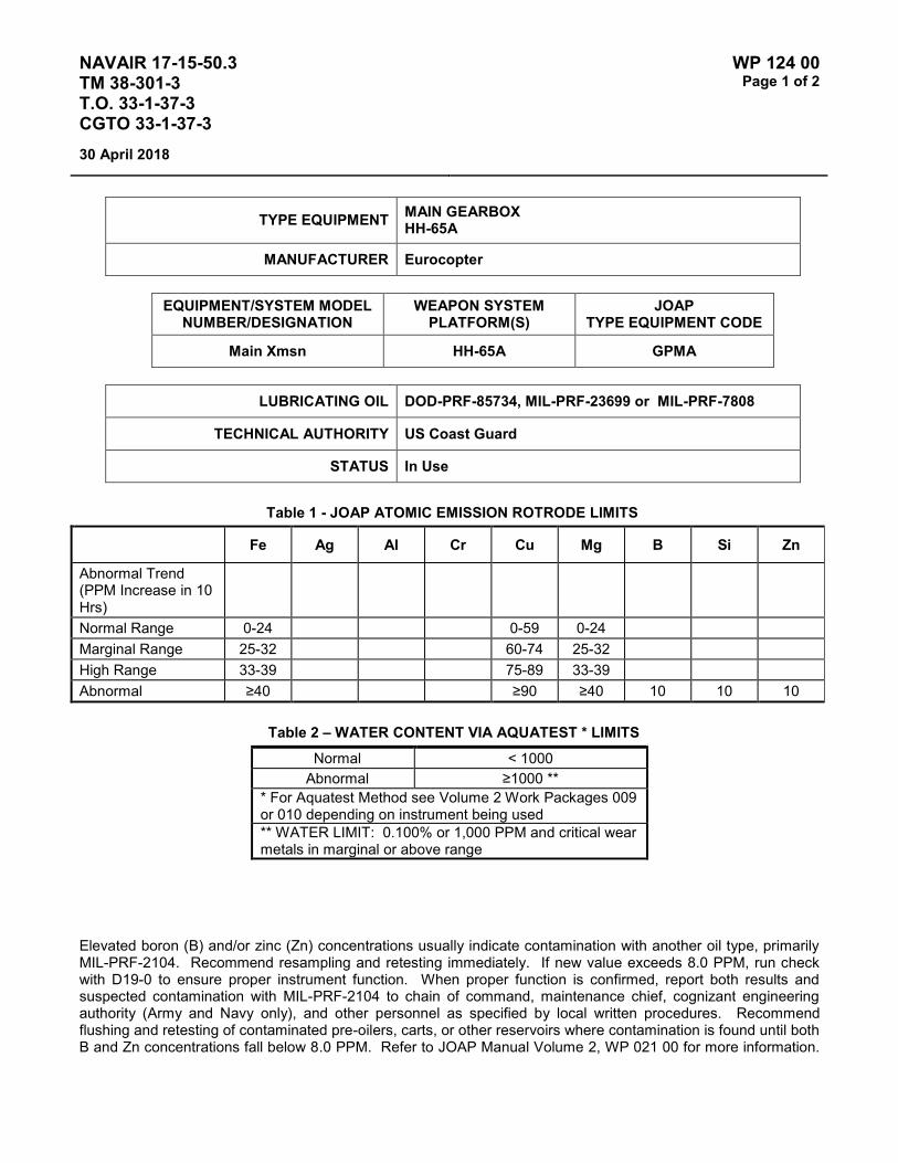
NAVAIR 17-15-50.3 TM 38-301-3 T.O. 33-1-37-3 CGTO 33-1-37-3
WP 124 00 Page 1 of 2
30 April 2018
TYPE EQUIPMENT MAIN GEARBOX HH-65A
MANUFACTURER Eurocopter
EQUIPMENT/SYSTEM MODEL NUMBER/DESIGNATION
WEAPON SYSTEM PLATFORM(S)
JOAP TYPE EQUIPMENT CODE
Main Xmsn HH-65A GPMA
LUBRICATING OIL DOD-PRF-85734, MIL-PRF-23699 or MIL-PRF-7808
TECHNICAL AUTHORITY US Coast Guard
STATUS In Use
Table 1 - JOAP ATOMIC EMISSION ROTRODE LIMITS
Fe Ag Al Cr Cu Mg B Si Zn
Abnormal Trend (PPM Increase in 10 Hrs)
Normal Range 0-24 0-59 0-24 Marginal Range 25-32 60-74 25-32 High Range 33-39 75-89 33-39 Abnormal ≥40 ≥90 ≥40 10 10 10
Table 2 – WATER CONTENT VIA AQUATEST * LIMITS Normal < 1000
Abnormal ≥1000 ** * For Aquatest Method see Volume 2 Work Packages 009 or 010 depending on instrument being used ** WATER LIMIT: 0.100% or 1,000 PPM and critical wear metals in marginal or above range
Elevated boron (B) and/or zinc (Zn) concentrations usually indicate contamination with another oil type, primarily MIL-PRF-2104. Recommend resampling and retesting immediately. If new value exceeds 8.0 PPM, run check with D19-0 to ensure proper instrument function. When proper function is confirmed, report both results and suspected contamination with MIL-PRF-2104 to chain of command, maintenance chief, cognizant engineering authority (Army and Navy only), and other personnel as specified by local written procedures. Recommend flushing and retesting of contaminated pre-oilers, carts, or other reservoirs where contamination is found until both B and Zn concentrations fall below 8.0 PPM. Refer to JOAP Manual Volume 2, WP 021 00 for more information.

NAVAIR 17-15-50.3 TM 38-301-3 T.O. 33-1-37-3 CGTO 33-1-37-3
WP 124 00 Page 2 of 2
30 April 2018
Recommend segregation of confirmed or suspected contaminated stocks, and submit information (batch no., lot no., MIL-PRF, nature of problem, etc.) on such stocks through the Defense supply deficiency reporting system.
Elevated silicon (Si) concentration usually indicates contamination with soil, sand, or dust. If aluminum (Al) is also elevated, this suggests the presence of clay or soil. Recommend resampling and retesting immediately. If new value exceeds 8.0 PPM, run check with D19-0 to ensure proper instrument function. When proper function is confirmed, report both results and suspected contamination with soil, sand, or dust to chain of command, maintenance chief, cognizant engineering authority (Army and Navy only), and other personnel as specified by local written procedures. Recommend flushing and retesting of contaminated pre-oilers, carts, or other reservoirs where contamination is found until silicon concentration falls below 8.0 PPM. Refer to JOAP Manual Volume 2, WP 021 00 for more information. Recommend segregation of confirmed or suspected contaminated stocks, and submit information (batch no., lot no., MIL-PRF, nature of problem, etc.) on such stocks through the Defense supply deficiency reporting system.

NAVAIR 17-15-50.3 TM 38-301-3 T.O. 33-1-37-3 CGTO 33-1-37-3
WP 125 00 Page 1 of 2
30 April 2018
TYPE EQUIPMENT TAIL ROTOR GEARBOX HH-65A
MANUFACTURER Eurocopter
EQUIPMENT/SYSTEM MODEL NUMBER/DESIGNATION
WEAPON SYSTEM PLATFORM(S)
JOAP TYPE EQUIPMENT CODE
90/Tail Gbx HH-65A GPTA
LUBRICATING OIL DOD-PRF-85734, MIL-PRF-23699 or MIL-PRF-7808
TECHNICAL AUTHORITY US Coast Guard
STATUS In Use
Table 1 - JOAP ATOMIC EMISSION ROTRODE LIMITS
Fe Ag Al Cr Cu Mg B Si Zn
Abnormal Trend (PPM Increase in 10 Hrs)
Normal Range 0-79 0-59 0-24 Marginal Range 80-89 60-74 25-32 High Range 90-99 75-89 33-39 Abnormal ≥100 ≥90 ≥40 10 10 10
Table 2 – WATER CONTENT VIA AQUATEST * LIMITS Normal < 1000
Abnormal ≥1000 ** * For Aquatest Method see Volume 2 Work Packages 009 or 010 depending on instrument being used ** WATER LIMIT: 0.100% or 1,000 PPM and critical wear metals in marginal or above range
Elevated boron (B) and/or zinc (Zn) concentrations usually indicate contamination with another oil type, primarily MIL-PRF-2104. Recommend resampling and retesting immediately. If new value exceeds 8.0 PPM, run check with D19-0 to ensure proper instrument function. When proper function is confirmed, report both results and suspected contamination with MIL-PRF-2104 to chain of command, maintenance chief, cognizant engineering authority (Army and Navy only), and other personnel as specified by local written procedures. Recommend flushing and retesting of contaminated pre-oilers, carts, or other reservoirs where contamination is found until both

NAVAIR 17-15-50.3 TM 38-301-3 T.O. 33-1-37-3 CGTO 33-1-37-3
WP 125 00 Page 2 of 2
30 April 2018
B and Zn concentrations fall below 8.0 PPM. Refer to JOAP Manual Volume 2, WP 021 00 for more information. Recommend segregation of confirmed or suspected contaminated stocks, and submit information (batch no., lot no., MIL-PRF, nature of problem, etc.) on such stocks through the Defense supply deficiency reporting system.
Elevated silicon (Si) concentration usually indicates contamination with soil, sand, or dust. If aluminum (Al) is also elevated, this suggests the presence of clay or soil. Recommend resampling and retesting immediately. If new value exceeds 8.0 PPM, run check with D19-0 to ensure proper instrument function. When proper function is confirmed, report both results and suspected contamination with soil, sand, or dust to chain of command, maintenance chief, cognizant engineering authority (Army and Navy only), and other personnel as specified by local written procedures. Recommend flushing and retesting of contaminated pre-oilers, carts, or other reservoirs where contamination is found until silicon concentration falls below 8.0 PPM. Refer to JOAP Manual Volume 2, WP 021 00 for more information. Recommend segregation of confirmed or suspected contaminated stocks, and submit information (batch no., lot no., MIL-PRF, nature of problem, etc.) on such stocks through the Defense supply deficiency reporting system.

NAVAIR 17-15-50.3 TM 38-301-3 T.O. 33-1-37-3 CGTO 33-1-37-3
WP 126 00 Page 1 of 2
30 April 2018
TYPE EQUIPMENT ENGINE GEARBOX T-38 (NAVY)
MANUFACTURER General Electric
EQUIPMENT/SYSTEM MODEL NUMBER/DESIGNATION
WEAPON SYSTEM PLATFORM(S)
JOAP TYPE EQUIPMENT CODE
Eng Gbx T-38 N/A
LUBRICATING OIL MIL-PRF-23699 or MIL-PRF-7808
TECHNICAL AUTHORITY NAVAIR
STATUS Aircraft Retired. WP retained for reference.
Table 1 - JOAP ATOMIC EMISSION ROTRODE LIMITS
Fe Ag Al Cr Cu Mg B Si Zn
Abnormal Trend (PPM Increase in 10 Hrs)
18 4 4 9
Normal Range 0-58 0-15 0-11 0-28 Marginal Range 59-70 16-18 12-13 29-34 High Range 71-86 19-23 14-16 35-42 Abnormal ≥87 ≥24 ≥17 ≥43 10 10 10
Elevated boron (B) and/or zinc (Zn) concentrations usually indicate contamination with another oil type, primarily MIL-PRF-2104. Recommend resampling and retesting immediately. If new value exceeds 8.0 PPM, run check with D19-0 to ensure proper instrument function. When proper function is confirmed, report both results and suspected contamination with MIL-PRF-2104 to chain of command, maintenance chief, cognizant engineering authority (Army and Navy only), and other personnel as specified by local written procedures. Recommend flushing and retesting of contaminated pre-oilers, carts, or other reservoirs where contamination is found until both B and Zn concentrations fall below 8.0 PPM. Refer to JOAP Manual Volume 2, WP 021 00 for more information. Recommend segregation of confirmed or suspected contaminated stocks, and submit information (batch no., lot no., MIL-PRF, nature of problem, etc.) on such stocks through the Defense supply deficiency reporting system.
Elevated silicon (Si) concentration usually indicates contamination with soil, sand, or dust. If aluminum (Al) is also elevated, this suggests the presence of clay or soil. Recommend resampling and retesting immediately. If new value exceeds 8.0 PPM, run check with D19-0 to ensure proper instrument function. When proper function is confirmed, report both results and suspected contamination with soil, sand, or dust to chain of command, maintenance chief, cognizant engineering authority (Army and Navy only), and other personnel as specified by local written procedures. Recommend flushing and retesting of contaminated pre-oilers, carts, or other reservoirs where contamination is found until silicon concentration falls below 8.0 PPM. Refer to JOAP Manual Volume 2, WP 021 00 for more information. Recommend segregation of confirmed or suspected contaminated stocks, and submit information (batch no., lot no., MIL-PRF, nature of problem, etc.) on such stocks through the Defense supply deficiency reporting system.

NAVAIR 17-15-50.3 TM 38-301-3 T.O. 33-1-37-3 CGTO 33-1-37-3
WP 126 00 Page 2 of 2
30 April 2018
This Page Intentionally Left Blank
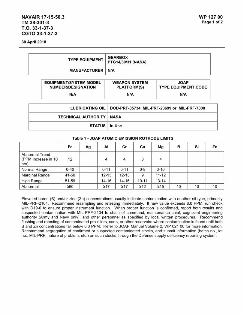
NAVAIR 17-15-50.3 TM 38-301-3 T.O. 33-1-37-3 CGTO 33-1-37-3
WP 127 00 Page 1 of 2
30 April 2018
TYPE EQUIPMENT GEARBOX PTG14/30/31 (NASA)
MANUFACTURER N/A
EQUIPMENT/SYSTEM MODEL NUMBER/DESIGNATION
WEAPON SYSTEM PLATFORM(S)
JOAP TYPE EQUIPMENT CODE
N/A N/A N/A
LUBRICATING OIL DOD-PRF-85734, MIL-PRF-23699 or MIL-PRF-7808
TECHNICAL AUTHORITY NASA
STATUS In Use
Table 1 - JOAP ATOMIC EMISSION ROTRODE LIMITS
Fe Ag Al Cr Cu Mg B Si Zn
Abnormal Trend (PPM Increase in 10 hrs)
12 4 4 3 4
Normal Range 0-40 0-11 0-11 0-8 0-10 Marginal Range 41-50 12-13 12-13 9 11-12 High Range 51-59 14-16 14-16 10-11 13-14 Abnormal ≥60 ≥17 ≥17 ≥12 ≥15 10 10 10
Elevated boron (B) and/or zinc (Zn) concentrations usually indicate contamination with another oil type, primarily MIL-PRF-2104. Recommend resampling and retesting immediately. If new value exceeds 8.0 PPM, run check with D19-0 to ensure proper instrument function. When proper function is confirmed, report both results and suspected contamination with MIL-PRF-2104 to chain of command, maintenance chief, cognizant engineering authority (Army and Navy only), and other personnel as specified by local written procedures. Recommend flushing and retesting of contaminated pre-oilers, carts, or other reservoirs where contamination is found until both B and Zn concentrations fall below 8.0 PPM. Refer to JOAP Manual Volume 2, WP 021 00 for more information. Recommend segregation of confirmed or suspected contaminated stocks, and submit information (batch no., lot no., MIL-PRF, nature of problem, etc.) on such stocks through the Defense supply deficiency reporting system.

NAVAIR 17-15-50.3 TM 38-301-3 T.O. 33-1-37-3 CGTO 33-1-37-3
WP 127 00 Page 2 of 2
30 April 2018
Elevated silicon (Si) concentration usually indicates contamination with soil, sand, or dust. If aluminum (Al) is also elevated, this suggests the presence of clay or soil. Recommend resampling and retesting immediately. If new value exceeds 8.0 PPM, run check with D19-0 to ensure proper instrument function. When proper function is confirmed, report both results and suspected contamination with soil, sand, or dust to chain of command, maintenance chief, cognizant engineering authority (Army and Navy only), and other personnel as specified by local written procedures. Recommend flushing and retesting of contaminated pre-oilers, carts, or other reservoirs where contamination is found until silicon concentration falls below 8.0 PPM. Refer to JOAP Manual Volume 2, WP 021 00 for more information. Recommend segregation of confirmed or suspected contaminated stocks, and submit information (batch no., lot no., MIL-PRF, nature of problem, etc.) on such stocks through the Defense supply deficiency reporting system.

NAVAIR 17-15-50.3 TM 38-301-3 T.O. 33-1-37-3 CGTO 33-1-37-3
WP 128 00 Page 1 of 2
30 April 2018
TYPE EQUIPMENT GEARBOX SYSTEMS MV-22, CV-22
MANUFACTURER Bell Boeing
EQUIPMENT/SYSTEM MODEL NUMBER/DESIGNATION
WEAPON SYSTEM PLATFORM(S)
JOAP TYPE EQUIPMENT CODE
Mid-Wing Gbx CV-22 GVBC
Prop Rotor Gbx CV-22 GVDC
Tilt Axis Gbx CV-22 GVJC
Emer Lube Res CV-22 DVAC
Mid-Wing Gbx MV-22 GVBM
Prop Rotor Gbx MV-22 GVDM
Tilt Axis Gbx MV-22 GVJM
Emer Lube Res MV-22 DVAM
LUBRICATING OIL DOD-PRF-85734, MIL-PRF-23699 or MIL-PRF-7808
TECHNICAL AUTHORITY NAVAIR
STATUS In Use
The MV-22 and CV-22 gearbox systems are comprised of one mid-wing gearbox (MWGB), two prop-rotor gearboxes (PRGB), two tilt-axis gearboxes and the emergency reservoir system (ELS). These systems use a fine filtration system of 3 and 40 micron filters, with desiccate filters to remove moisture from the air. Based on the filtration design, RCM analysis and recommendation from oil analysis experts in NAVAIR 4.4, JOAP analysis has been determined to be an ineffective preventive maintenance task for the drive system.
The current filtration consists of a manifold assembly, filter bowl assembly, primary filter element assembly and secondary filter element assembly. The oil enters the filter assembly from the oil coolers at an unregulated pressure of 93 to 170 PSIG. Pressure regulated and filtered oil is delivered through the filter, which acts to remove air and debris scavenged from the PRGB cavities before returning to the reservoir. This design effectively cleanses the V-22 drive system gearbox lubricants during normal operations.

NAVAIR 17-15-50.3 TM 38-301-3 T.O. 33-1-37-3 CGTO 33-1-37-3
WP 128 00 Page 2 of 2
30 April 2018
Table 1 – WATER CONTENT VIA AQUATEST * LIMITS Normal ≤ 1000
Abnormal > 1000 * For Aquatest Method see Volume 2 Work Packages 009 or 010 depending on instrument being used
Should the desiccant filter become saturated and change from the normal blue color, it can no longer adequately remove moisture from air inhaled into the gearbox. Oil samples shall be taken and analyzed for water content for this condition and as further directed by the IETMS. Water limits are 1000 PPM or 0.100 percent. If water content exceeds the allowed limits, (1) the drive system oil shall be drained and the system re-serviced and (2) the desiccant filter must be changed. Refer to the applicable V-22 IETMS for any additional conditions requiring analysis and details on the associated maintenance requirements.
NOTE
Water Content Testing is only applicable to Navy and Marine Corps Aircraft. USAF Aircraft are not tested for Water Content.

NAVAIR 17-15-50.3 TM 38-301-3 T.O. 33-1-37-3 CGTO 33-1-37-3
WP 129 00 Page 1 of 2
30 April 2018
TYPE EQUIPMENT GTCP36-50 (APU) A-10
MANUFACTURER Honeywell Aerospace
EQUIPMENT/SYSTEM MODEL NUMBER/DESIGNATION
WEAPON SYSTEM PLATFORM(S)
JOAP TYPE EQUIPMENT CODE
GTCP36-50 A-10 DCBA
LUBRICATING OIL MIL-PRF-7808 or MIL-PRF-23699
TECHNICAL AUTHORITY Air Force
STATUS In Use
Table 1 - JOAP ATOMIC EMISSION ROTRODE LIMITS
Fe Ag Al Cr Cu Mg Sn B Si Zn
Abnormal Trend (PPM Increase in 10 Hrs)
5 2 2 2 6 2 5
Normal Range 0-12 0-3 0-3 0-3 0-15 0-3 0-12 Marginal Range 13-16 N/A N/A N/A 16-20 N/A 13-15 High Range 17-20 4-5 4-5 4-5 21-23 4-5 16-18 Abnormal ≥21 ≥6 ≥6 ≥ ≥24 ≥6 ≥19 10 10 10
Elevated boron (B) and/or zinc (Zn) concentrations usually indicate contamination with another oil type, primarily MIL-PRF-2104. Recommend resampling and retesting immediately. If new value exceeds 8.0 PPM, run check with D19-0 to ensure proper instrument function. When proper function is confirmed, report both results and suspected contamination with MIL-PRF-2104 to chain of command, maintenance chief, cognizant engineering authority (Army and Navy only), and other personnel as specified by local written procedures. Recommend flushing and retesting of contaminated pre-oilers, carts, or other reservoirs where contamination is found until both B and Zn concentrations fall below 8.0 PPM. Refer to JOAP Manual Volume 2, WP 021 00 for more information. Recommend segregation of confirmed or suspected contaminated stocks, and submit information (batch no., lot no., MIL-PRF, nature of problem, etc.) on such stocks through the Defense supply deficiency reporting system.

NAVAIR 17-15-50.3 TM 38-301-3 T.O. 33-1-37-3 CGTO 33-1-37-3
WP 129 00 Page 2 of 2
30 April 2018
Elevated silicon (Si) concentration usually indicates contamination with soil, sand, or dust. If aluminum (Al) is also elevated, this suggests the presence of clay or soil. Recommend resampling and retesting immediately. If new value exceeds 8.0 PPM, run check with D19-0 to ensure proper instrument function. When proper function is confirmed, report both results and suspected contamination with soil, sand, or dust to chain of command, maintenance chief, cognizant engineering authority (Army and Navy only), and other personnel as specified by local written procedures. Recommend flushing and retesting of contaminated pre-oilers, carts, or other reservoirs where contamination is found until silicon concentration falls below 8.0 PPM. Refer to JOAP Manual Volume 2, WP 021 00 for more information. Recommend segregation of confirmed or suspected contaminated stocks, and submit information (batch no., lot no., MIL-PRF, nature of problem, etc.) on such stocks through the Defense supply deficiency reporting system.
Fe Starter clutch shaft Oil pump gear, shaft Generator and hydraulic drive gears Ring gear Planetary & sun gears, and shafts
Fe & Cr Generator and hydraulic pad bearings Main drive bearings Idler gear bearings Planetary gear bearings
Fe Cr & Mo Main shaft bearings
Al Gearbox housing Oil pump housing
Cu & Sn Oil pump bushing Starter clutch bearings
Ag (Plating) Main shaft rear bearing

NAVAIR 17-15-50.3 TM 38-301-3 T.O. 33-1-37-3 CGTO 33-1-37-3
WP 130 00 Page 1 of 2
30 April 2018
TYPE EQUIPMENT GTCP36-16A (APU) C-27
MANUFACTURER Honeywell Aerospace
EQUIPMENT/SYSTEM MODEL NUMBER/DESIGNATION
WEAPON SYSTEM PLATFORM(S)
JOAP TYPE EQUIPMENT CODE
GTCP36-16 C-27 DCGA
LUBRICATING OIL MIL-PRF-7808 or MIL-PRF-23699
TECHNICAL AUTHORITY US Coast Guard
STATUS In Use
Table 1 - JOAP ATOMIC EMISSION ROTRODE LIMITS
Fe Ag Al Cr Cu Mg Ni Pb Si Sn Ti Mo B Zn
Abnormal Trend (PPM Increase in 10 Hrs)
5 2 2 2 6 2 4 8 6 5 2 4
Normal Range 0-12 0-3 0-3 0-3 0-15 0-8 0-5 0-
26 0-15
0-12 0-3 0-5
Marginal Range 13-16 4 4 4 16-20
9-11 6 27-
36 16-17
13-15 4 6
High Range 17-20 5 5 5 21-23
12-14 7 37-
42 18-19
16-18 5 7
Abnormal ≥21 ≥6 ≥6 ≥6 ≥24 ≥15 ≥8 ≥43 ≥20 ≥19 ≥6 ≥8 10 10
Elevated boron (B) and/or zinc (Zn) concentrations usually indicate contamination with another oil type, primarily MIL-PRF-2104. Recommend resampling and retesting immediately. If new value exceeds 8.0 PPM, run check with D19-0 to ensure proper instrument function. When proper function is confirmed, report both results and suspected contamination with MIL-PRF-2104 to chain of command, maintenance chief, cognizant engineering authority (Army and Navy only), and other personnel as specified by local written procedures. Recommend flushing and retesting of contaminated pre-oilers, carts, or other reservoirs where contamination is found until both B and Zn concentrations fall below 8.0 PPM. Refer to JOAP Manual Volume 2, WP 021 00 for more information. Recommend segregation of confirmed or suspected contaminated stocks, and submit information (batch no., lot no., MIL-PRF, nature of problem, etc.) on such stocks through the Defense supply deficiency reporting system.

NAVAIR 17-15-50.3 TM 38-301-3 T.O. 33-1-37-3 CGTO 33-1-37-3
WP 130 00 Page 2 of 2
30 April 2018
This Page Intentionally Left Blank

NAVAIR 17-15-50.3 TM 38-301-3 T.O. 33-1-37-3 CGTO 33-1-37-3
WP 131 00 Page 1 of 2
30 April 2018
TYPE EQUIPMENT GTCP36-200/201C (APU) (C-2, F-18)
MANUFACTURER Honeywell Aerospace
EQUIPMENT/SYSTEM MODEL NUMBER/DESIGNATION
WEAPON SYSTEM PLATFORM(S)
JOAP TYPE EQUIPMENT CODE
GTCP36-200 F-18 DCDA
GTCP36-201C C-2 DCAA
LUBRICATING OIL MIL-PRF-7808 or MIL-PRF-23699
TECHNICAL AUTHORITY NAVAIR
STATUS In Use
Table 1 - JOAP ATOMIC EMISSION ROTRODE LIMITS
Fe Ag Al Cr Cu Mg Ti B Si Zn
Abnormal Trend (PPM Increase in 10 Hrs)
4 2 2 2 3 3
Normal Range 0-9 0-4 0-3 0-3 0-5 0-5 Marginal Range 10 5 4 4 6 6 High Range 11-12 6 5 5 7-8 7-8 Abnormal ≥13 ≥7 ≥6 ≥6 ≥9 ≥9 10 10 10
Elevated boron (B) and/or zinc (Zn) concentrations usually indicate contamination with another oil type, primarily MIL-PRF-2104. Recommend resampling and retesting immediately. If new value exceeds 8.0 PPM, run check with D19-0 to ensure proper instrument function. When proper function is confirmed, report both results and suspected contamination with MIL-PRF-2104 to chain of command, maintenance chief, cognizant engineering authority (Army and Navy only), and other personnel as specified by local written procedures. Recommend flushing and retesting of contaminated pre-oilers, carts, or other reservoirs where contamination is found until both B and Zn concentrations fall below 8.0 PPM. Refer to JOAP Manual Volume 2, WP 021 00 for more information. Recommend segregation of confirmed or suspected contaminated stocks, and submit information (batch no., lot no., MIL-PRF, nature of problem, etc.) on such stocks through the Defense supply deficiency reporting system.
Elevated silicon (Si) concentration usually indicates contamination with soil, sand, or dust. If aluminum (Al) is also elevated, this suggests the presence of clay or soil. Recommend resampling and retesting immediately. If new value exceeds 8.0 PPM, run check with D19-0 to ensure proper instrument function. When proper function is confirmed, report both results and suspected contamination with soil, sand, or dust to chain of command, maintenance chief, cognizant engineering authority (Army and Navy only), and other personnel as specified by local written procedures. Recommend flushing and retesting of contaminated pre-oilers, carts, or other reservoirs where contamination is found until silicon concentration falls below 8.0 PPM. Refer to JOAP Manual Volume 2,

NAVAIR 17-15-50.3 TM 38-301-3 T.O. 33-1-37-3 CGTO 33-1-37-3
WP 131 00 Page 2 of 2
30 April 2018
WP 021 00 for more information. Recommend segregation of confirmed or suspected contaminated stocks, and submit information (batch no., lot no., MIL-PRF, nature of problem, etc.) on such stocks through the Defense supply deficiency reporting system.
In the event any critical element (wear metal) increases to the high range or an abnormal trend is indicated, take the following steps:
1. Confirm by obtaining check sample.
2. Drain oil in accordance with maintenance manual Al-C2AHA-GAI-200, reservice, conduct a 15-minute operational run, and send oil sample to JOAP/NOAP lab.
3. If metal concentration range is abnormal, replace APU.
4. If metal concentration range is below range, release for flight and take additional samples after 1 hour operation. If an abnormal trend is indicated, recommend removal, and request an engineering investigation.
5. Recommend close surveillance for the next 10 operating hours after the initial abnormal analysis.
NOTE
The requirement for routine oil analysis on the GTCP36-200 APU in the F-18 series aircraft has been deleted. Evaluation criteria is being retained for reference and use as directed by cognizant authority.

NAVAIR 17-15-50.3 TM 38-301-3 T.O. 33-1-37-3 CGTO 33-1-37-3
WP 132 00 Page 1 of 2
30 April 2018
TYPE EQUIPMENT GTCP36-201A (APU) (S-3A/B)
MANUFACTURER Honeywell Aerospace
EQUIPMENT/SYSTEM MODEL NUMBER/DESIGNATION
WEAPON SYSTEM PLATFORM(S)
JOAP TYPE EQUIPMENT CODE
GTCP36-201A S-3A/B DCAB
LUBRICATING OIL MIL-PRF-7808 or MIL-PRF-23699
TECHNICAL AUTHORITY NAVAIR
STATUS Aircraft and APU retired. WP retained for reference.
Table 1 - JOAP ATOMIC EMISSION ROTRODE LIMITS
Fe Ag Al Cr Cu Mg Ti B Si Zn
Abnormal Trend (PPM Increase in 10 Hrs)
4 2 2 4 3 3
Normal Range 0-9 0-4 0-3 0-6 0-5 0-5 Marginal Range 10 5 4 7-9 6 6 High Range 11-12 6 5 10-12 7-8 7-8 Abnormal ≥13 ≥7 ≥6 ≥13 ≥9 ≥9 10 10 10
Elevated boron (B) and/or zinc (Zn) concentrations usually indicate contamination with another oil type, primarily MIL-PRF-2104. Recommend resampling and retesting immediately. If new value exceeds 8.0 PPM, run check with D19-0 to ensure proper instrument function. When proper function is confirmed, report both results and suspected contamination with MIL-PRF-2104 to chain of command, maintenance chief, cognizant engineering authority (Army and Navy only), and other personnel as specified by local written procedures. Recommend flushing and retesting of contaminated pre-oilers, carts, or other reservoirs where contamination is found until both B and Zn concentrations fall below 8.0 PPM. Refer to JOAP Manual Volume 2, WP 021 00 for more information. Recommend segregation of confirmed or suspected contaminated stocks, and submit information (batch no., lot no., MIL-PRF, nature of problem, etc.) on such stocks through the Defense supply deficiency reporting system.

NAVAIR 17-15-50.3 TM 38-301-3 T.O. 33-1-37-3 CGTO 33-1-37-3
WP 132 00 Page 2 of 2
30 April 2018
Elevated silicon (Si) concentration usually indicates contamination with soil, sand, or dust. If aluminum (Al) is also elevated, this suggests the presence of clay or soil. Recommend resampling and retesting immediately. If new value exceeds 8.0 PPM, run check with D19-0 to ensure proper instrument function. When proper function is confirmed, report both results and suspected contamination with soil, sand, or dust to chain of command, maintenance chief, cognizant engineering authority (Army and Navy only), and other personnel as specified by local written procedures. Recommend flushing and retesting of contaminated pre-oilers, carts, or other reservoirs where contamination is found until silicon concentration falls below 8.0 PPM. Refer to JOAP Manual Volume 2, WP 021 00 for more information. Recommend segregation of confirmed or suspected contaminated stocks, and submit information (batch no., lot no., MIL-PRF, nature of problem, etc.) on such stocks through the Defense supply deficiency reporting system.
In the event any critical element (wear metal) increases to the high range or an abnormal trend is indicated, take the following steps:
1. Confirm by obtaining check sample.
2. Drain oil in accordance with maintenance manual NAVAIR 01-S3AAA-2-4.4.1, flush or change filters (2), reservice, conduct a 15-minute operational run, and send oil sample to JOAP/NOAP lab.
3. If metal concentration range is abnormal, replace APU.
4. If metal concentration range is below range, release for flight and take additional samples after 1 hour operation. If an abnormal trend is indicated, recommend removal and request an engineering investigation.
5. Recommend close surveillance for the next 10 operating hours after the initial abnormal analysis.

NAVAIR 17-15-50.3 TM 38-301-3 T.O. 33-1-37-3 CGTO 33-1-37-3
WP 133 00 Page 1 of 2
30 April 2018
TYPE EQUIPMENT GTCP165-1 (APU) (C-5)
MANUFACTURER Honeywell Aerospace
EQUIPMENT/SYSTEM MODEL NUMBER/DESIGNATION
WEAPON SYSTEM PLATFORM(S)
JOAP TYPE EQUIPMENT CODE
GTCP165-1 C-5 DLAA
LUBRICATING OIL MIL-PRF-7808 or MIL-PRF-23699
TECHNICAL AUTHORITY Air Force
STATUS In Use
Table 1 - JOAP ATOMIC EMISSION ROTRODE LIMITS
Fe Ag Al Cr Cu Mg B Si Zn
Abnormal Trend (PPM Increase in 10 Hrs)
10 2 4 2 4 10
Normal Range 0-33 0-3 0-10 0-3 0-13 0-33 Marginal Range 34-40 N/A 11-12 4 14-16 34-40 High Range 41-49 4 13-14 5 17-19 41-49 Abnormal ≥50 ≥5 ≥15 ≥6 ≥20 ≥50 10 10 10
Elevated boron (B) and/or zinc (Zn) concentrations usually indicate contamination with another oil type, primarily MIL-PRF-2104. Recommend resampling and retesting immediately. If new value exceeds 8.0 PPM, run check with D19-0 to ensure proper instrument function. When proper function is confirmed, report both results and suspected contamination with MIL-PRF-2104 to chain of command, maintenance chief, cognizant engineering authority (Army and Navy only), and other personnel as specified by local written procedures. Recommend flushing and retesting of contaminated pre-oilers, carts, or other reservoirs where contamination is found until both B and Zn concentrations fall below 8.0 PPM. Refer to JOAP Manual Volume 2, WP 021 00 for more information. Recommend segregation of confirmed or suspected contaminated stocks, and submit information (batch no., lot no., MIL-PRF, nature of problem, etc.) on such stocks through the Defense supply deficiency reporting system.

NAVAIR 17-15-50.3 TM 38-301-3 T.O. 33-1-37-3 CGTO 33-1-37-3
WP 133 00 Page 2 of 2
30 April 2018
Elevated silicon (Si) concentration usually indicates contamination with soil, sand, or dust. If aluminum (Al) is also elevated, this suggests the presence of clay or soil. Recommend resampling and retesting immediately. If new value exceeds 8.0 PPM, run check with D19-0 to ensure proper instrument function. When proper function is confirmed, report both results and suspected contamination with soil, sand, or dust to chain of command, maintenance chief, cognizant engineering authority (Army and Navy only), and other personnel as specified by local written procedures. Recommend flushing and retesting of contaminated pre-oilers, carts, or other reservoirs where contamination is found until silicon concentration falls below 8.0 PPM. Refer to JOAP Manual Volume 2, WP 021 00 for more information. Recommend segregation of confirmed or suspected contaminated stocks, and submit information (batch no., lot no., MIL-PRF, nature of problem, etc.) on such stocks through the Defense supply deficiency reporting system.

NAVAIR 17-15-50.3 TM 38-301-3 T.O. 33-1-37-3 CGTO 33-1-37-3
WP 134 00 Page 1 of 2
30 April 2018
TYPE EQUIPMENT GTCP85-98/TE-8A (APU) (C-9) (AIR FORCE)
MANUFACTURER Honeywell Aerospace
EQUIPMENT/SYSTEM MODEL NUMBER/DESIGNATION
WEAPON SYSTEM PLATFORM(S)
JOAP TYPE EQUIPMENT CODE
GTCP85-98/TE-8A C-9 N/A
LUBRICATING OIL MIL-PRF-7808 or MIL-PRF-23699
TECHNICAL AUTHORITY Air Force
STATUS Aircraft and APU retired. WP retained for reference.
Table 1 - JOAP ATOMIC EMISSION ROTRODE LIMITS
Fe Ag Al Cr Cu Mg Sn B Si Zn
Abnormal Trend (PPM Increase in 10 Hrs)
2 2 2 2 2 2 5
Normal Range 0-5 0-1 0-1 0-1 0-5 0-3 0-11 Marginal Range 6 N/A N/A N/A 6-7 N/A 12-13 High Range 7 2 2 2 8 4 14 Abnormal ≥8 ≥3 ≥3 ≥3 ≥9 ≥ ≥15 10 10 10
Elevated boron (B) and/or zinc (Zn) concentrations usually indicate contamination with another oil type, primarily MIL-PRF-2104. Recommend resampling and retesting immediately. If new value exceeds 8.0 PPM, run check with D19-0 to ensure proper instrument function. When proper function is confirmed, report both results and suspected contamination with MIL-PRF-2104 to chain of command, maintenance chief, cognizant engineering authority (Army and Navy only), and other personnel as specified by local written procedures. Recommend flushing and retesting of contaminated pre-oilers, carts, or other reservoirs where contamination is found until both B and Zn concentrations fall below 8.0 PPM. Refer to JOAP Manual Volume 2, WP 021 00 for more information. Recommend segregation of confirmed or suspected contaminated stocks, and submit information (batch no., lot no., MIL-PRF, nature of problem, etc.) on such stocks through the Defense supply deficiency reporting system.
Elevated silicon (Si) concentration usually indicates contamination with soil, sand, or dust. If aluminum (Al) is also elevated, this suggests the presence of clay or soil. Recommend resampling and retesting immediately. If new value exceeds 8.0 PPM, run check with D19-0 to ensure proper instrument function. When proper function is confirmed, report both results and suspected contamination with soil, sand, or dust to chain of command, maintenance chief, cognizant engineering authority (Army and Navy only), and other personnel as specified by local written procedures. Recommend flushing and retesting of contaminated pre-oilers, carts, or other reservoirs where contamination is found until silicon concentration falls below 8.0 PPM. Refer to JOAP Manual Volume 2, WP 021 00 for more information. Recommend segregation of confirmed or suspected contaminated stocks, and

NAVAIR 17-15-50.3 TM 38-301-3 T.O. 33-1-37-3 CGTO 33-1-37-3
WP 134 00 Page 2 of 2
30 April 2018
submit information (batch no., lot no., MIL-PRF, nature of problem, etc.) on such stocks through the Defense supply deficiency reporting system.

NAVAIR 17-15-50.3 TM 38-301-3 T.O. 33-1-37-3 CGTO 33-1-37-3
WP 135 00 Page 1 of 2
30 April 2018
TYPE EQUIPMENT GTCP85-71 (APU) (C-130)
MANUFACTURER Honeywell Aerospace
EQUIPMENT/SYSTEM MODEL NUMBER/DESIGNATION
WEAPON SYSTEM PLATFORM(S)
JOAP TYPE EQUIPMENT CODE
GTC85-71 C-130 DGEA
LUBRICATING OIL MIL-PRF-7808 or MIL-PRF-23699
TECHNICAL AUTHORITY Air Force
STATUS Aircraft and APU retired. WP retained for reference.
Table 1 - JOAP ATOMIC EMISSION ROTRODE LIMITS
Fe Ag Al Cr Cu Mg B Si Zn
Abnormal Trend (PPM Increase in 10 Hrs)
8 * 3 2 3 3
Normal Range 0-29 0-1 0-6 0-2 0-8 0-7 Marginal Range 30-35 N/A 7 N/A 9-10 8 High Range 36-43 2 8-9 3 11-12 9-10 Abnormal ≥44 ≥3 ≥10 ≥4 ≥13 ≥11 10 10 10
Elevated boron (B) and/or zinc (Zn) concentrations usually indicate contamination with another oil type, primarily MIL-PRF-2104. Recommend resampling and retesting immediately. If new value exceeds 8.0 PPM, run check with D19-0 to ensure proper instrument function. When proper function is confirmed, report both results and suspected contamination with MIL-PRF-2104 to chain of command, maintenance chief, cognizant engineering authority (Army and Navy only), and other personnel as specified by local written procedures. Recommend flushing and retesting of contaminated pre-oilers, carts, or other reservoirs where contamination is found until both B and Zn concentrations fall below 8.0 PPM. Refer to JOAP Manual Volume 2, WP 021 00 for more information. Recommend segregation of confirmed or suspected contaminated stocks, and submit information (batch no., lot no., MIL-PRF, nature of problem, etc.) on such stocks through the Defense supply deficiency reporting system.
Elevated silicon (Si) concentration usually indicates contamination with soil, sand, or dust. If aluminum (Al) is also elevated, this suggests the presence of clay or soil. Recommend resampling and retesting immediately. If new value exceeds 8.0 PPM, run check with D19-0 to ensure proper instrument function. When proper function is confirmed, report both results and suspected contamination with soil, sand, or dust to chain of command, maintenance chief, cognizant engineering authority (Army and Navy only), and other personnel as specified by local written procedures. Recommend flushing and retesting of contaminated pre-oilers, carts, or other reservoirs where contamination is found until silicon concentration falls below 8.0 PPM. Refer to JOAP Manual Volume 2,

NAVAIR 17-15-50.3 TM 38-301-3 T.O. 33-1-37-3 CGTO 33-1-37-3
WP 135 00 Page 2 of 2
30 April 2018
WP 021 00 for more information. Recommend segregation of confirmed or suspected contaminated stocks, and submit information (batch no., lot no., MIL-PRF, nature of problem, etc.) on such stocks through the Defense supply deficiency reporting system.
Fe & Cr Bearing rollers and races.
Fe & Ni Oil pump gears and shaft.
Fe & Cr Ni Turbine and aft compressor carbon seal races. Turbine section bearing spacer and housing. Aft compressor section shaft and bearing mount. Accessory assembly carbon seal rotors, gears, shafts, bearing housing, retainers and carries. Output geardrive seal runners and bearing retainer gasket seals. Forward compressor assembly shaft and inlet compressor seal races.
Cu Oil pump bushings.
Cu & Ag Turbine section bearing cages.
Cu & Sn Output geardrive bearing cages. Aft compressor section bearing cages. Oil pump gear pins.
Cu & Ag Sn Accessory assembly bearing cages.
Al & Cu Forward compressor assembly bearing and seal housing. Oil pump body, cover and plate assembly.
Mg Accessory case assembly.
Al & Mg Output geardrive housing.
Al & Ni Cr Output geardrive gears.
Ni & Cr Fe Turbine wheel shaft.
Sn & Fe Cu Forward compressor assembly sleeve bearing.

NAVAIR 17-15-50.3 TM 38-301-3 T.O. 33-1-37-3 CGTO 33-1-37-3
WP 136 00 Page 1 of 2
30 April 2018
TYPE EQUIPMENT GTCP85-106 (APU) (C-141)
MANUFACTURER Honeywell Aerospace
EQUIPMENT/SYSTEM MODEL NUMBER/DESIGNATION
WEAPON SYSTEM PLATFORM(S)
JOAP TYPE EQUIPMENT CODE
GTC85-106 C-141 DJAA
LUBRICATING OIL MIL-PRF-7808 or MIL-PRF-23699
TECHNICAL AUTHORITY Air Force
STATUS Aircraft and APU retired. WP retained for reference.
Table 1 - JOAP ATOMIC EMISSION ROTRODE LIMITS
*Fe Ag Al Cr *Cu Mg B Si Zn
Abnormal Trend (PPM Increase in 10 Hrs)
13 2 4 2 5 3
Normal Range 0-43 0-2 0-10 0-4 0-20 0-6 Marginal Range 44-53 N/A 11-12 5 21-28 7 High Range 54-65 3 13-14 6 29-34 8-9 Abnormal ≥66 ≥4 ≥15 ≥7 ≥35 ≥10 10 10 10 NOTE: * Increase in Fe and Cu indicates discrepancy in starter clutch area.
Elevated boron (B) and/or zinc (Zn) concentrations usually indicate contamination with another oil type, primarily MIL-PRF-2104. Recommend resampling and retesting immediately. If new value exceeds 8.0 PPM, run check with D19-0 to ensure proper instrument function. When proper function is confirmed, report both results and suspected contamination with MIL-PRF-2104 to chain of command, maintenance chief, cognizant engineering authority (Army and Navy only), and other personnel as specified by local written procedures. Recommend flushing and retesting of contaminated pre-oilers, carts, or other reservoirs where contamination is found until both B and Zn concentrations fall below 8.0 PPM. Refer to JOAP Manual Volume 2, WP 021 00 for more information. Recommend segregation of confirmed or suspected contaminated stocks, and submit information (batch no., lot no., MIL-PRF, nature of problem, etc.) on such stocks through the Defense supply deficiency reporting system.
Elevated silicon (Si) concentration usually indicates contamination with soil, sand, or dust. If aluminum (Al) is also elevated, this suggests the presence of clay or soil. Recommend resampling and retesting immediately. If new value exceeds 8.0 PPM, run check with D19-0 to ensure proper instrument function. When proper function is confirmed, report both results and suspected contamination with soil, sand, or dust to chain of command, maintenance chief, cognizant engineering authority (Army and Navy only), and other personnel as specified by local written procedures. Recommend flushing and retesting of contaminated pre-oilers, carts, or other reservoirs where contamination is found until silicon concentration falls below 8.0 PPM. Refer to JOAP Manual Volume 2, WP 021 00 for more information. Recommend segregation of confirmed or suspected contaminated stocks, and

NAVAIR 17-15-50.3 TM 38-301-3 T.O. 33-1-37-3 CGTO 33-1-37-3
WP 136 00 Page 2 of 2
30 April 2018
submit information (batch no., lot no., MIL-PRF, nature of problem, etc.) on such stocks through the Defense supply deficiency reporting system.
Fe & Cr Bearing rollers and races
Al Bearing sleeve
Fe & Ni Oil pump gears and shaft
Fe & Cr Ni Turbine and aft compressor carbon seal races Turbine section bearing spacer and housing Aft compressor section shaft and bearing mount Accessory assembly carbon seal rotors, gears, shafts, bearing housing, retainers and carries Output geardrive seal runners and bearing retainer gasket seals Forward compressor assembly shaft and inlet compressor seal races
Cu Oil pump bushings
Cu & Ag Turbine section bearing cages
Cu & Sn Output geardrive bearing cages Aft compressor section bearing cages Oil pump gear pins
Cu & Ag Sn Accessory assembly bearing cages
Al & Cu Forward compressor assembly bearing and seal housing Oil pump body, cover and plate assembly
Mg Accessory case assembly GTCP85-106 (Cont.) (C-141 APU)
Al & Mg Output geardrive housing
Al & Ni Cr Output geardrive gears
Ni & Cr Fe Turbine wheel shaft
Sn & Fe Cu Forward compressor assembly sleeve bearing

NAVAIR 17-15-50.3 TM 38-301-3 T.O. 33-1-37-3 CGTO 33-1-37-3
WP 137 00 Page 1 of 2
30 April 2018
TYPE EQUIPMENT T62T-11 (APU) CH-46A/D/F, NCH-46A, UH-46A (NAVY)
MANUFACTURER Solar
EQUIPMENT/SYSTEM MODEL NUMBER/DESIGNATION
WEAPON SYSTEM PLATFORM(S)
JOAP TYPE EQUIPMENT CODE
T62T-11 H-46 DBAA
LUBRICATING OIL MIL-PRF-7808 or MIL-PRF-23699
TECHNICAL AUTHORITY NAVAIR
STATUS In Use
Table 1 - JOAP ATOMIC EMISSION ROTRODE LIMITS
Fe Ag Al Cr Cu Mg B Si Zn
Abnormal Trend (PPM Increase in 10 Hrs)
4 4 3 3
Normal Range 0-13 0-10 0-8 0-8 Marginal Range 14-16 11-12 9 9 High Range 17-19 13-14 10-11 10-11 Abnormal ≥20 ≥15 ≥12 ≥12 10 10 10
Elevated boron (B) and/or zinc (Zn) concentrations usually indicate contamination with another oil type, primarily MIL-PRF-2104. Recommend resampling and retesting immediately. If new value exceeds 8.0 PPM, run check with D19-0 to ensure proper instrument function. When proper function is confirmed, report both results and suspected contamination with MIL-PRF-2104 to chain of command, maintenance chief, cognizant engineering authority (Army and Navy only), and other personnel as specified by local written procedures. Recommend flushing and retesting of contaminated pre-oilers, carts, or other reservoirs where contamination is found until both B and Zn concentrations fall below 8.0 PPM. Refer to JOAP Manual Volume 2, WP 021 00 for more information. Recommend segregation of confirmed or suspected contaminated stocks, and submit information (batch no., lot no., MIL-PRF, nature of problem, etc.) on such stocks through the Defense supply deficiency reporting system.
Elevated silicon (Si) concentration usually indicates contamination with soil, sand, or dust. If aluminum (Al) is also elevated, this suggests the presence of clay or soil. Recommend resampling and retesting immediately. If new value exceeds 8.0 PPM, run check with D19-0 to ensure proper instrument function. When proper function is confirmed, report both results and suspected contamination with soil, sand, or dust to chain of command, maintenance chief, cognizant engineering authority (Army and Navy only), and other personnel as specified by local written procedures. Recommend flushing and retesting of contaminated pre-oilers, carts, or other reservoirs where contamination is found until silicon concentration falls below 8.0 PPM. Refer to JOAP Manual Volume 2, WP 021 00 for more information. Recommend segregation of confirmed or suspected contaminated stocks, and

NAVAIR 17-15-50.3 TM 38-301-3 T.O. 33-1-37-3 CGTO 33-1-37-3
WP 137 00 Page 2 of 2
30 April 2018
submit information (batch no., lot no., MIL-PRF, nature of problem, etc.) on such stocks through the Defense supply deficiency reporting system.
NOTE
The point of contact for this equipment is Tad Tsukida (Code 05325), DSN 993-7801 or FTS (510) 263-7801.

NAVAIR 17-15-50.3 TM 38-301-3 T.O. 33-1-37-3 CGTO 33-1-37-3
WP 138 00 Page 1 of 2
30 April 2018
TYPE EQUIPMENT GTCP95-2/-3 (APU) P-3 (NAVY)
MANUFACTURER Honeywell Aerospace
EQUIPMENT/SYSTEM MODEL NUMBER/DESIGNATION
WEAPON SYSTEM PLATFORM(S)
JOAP TYPE EQUIPMENT CODE
GTCP95-2/-3 P-3 DKAA
LUBRICATING OIL MIL-PRF-7808 or MIL-PRF-23699
TECHNICAL AUTHORITY NAVAIR
STATUS In Use
Table 1 - JOAP ATOMIC EMISSION ROTRODE LIMITS
Fe Ag Al Cr Cu Mg B Si Zn
Abnormal Trend (PPM Increase in 10 Hrs)
6 4 4 6
Normal Range 0-18 0-12 0-13 0-20 Marginal Range 19-22 13-15 14-16 21-25 High Range 23-26 16-17 17-19 26-29 Abnormal ≥27 ≥18 ≥20 ≥30 10 10 10
Elevated boron (B) and/or zinc (Zn) concentrations usually indicate contamination with another oil type, primarily MIL-PRF-2104. Recommend resampling and retesting immediately. If new value exceeds 8.0 PPM, run check with D19-0 to ensure proper instrument function. When proper function is confirmed, report both results and suspected contamination with MIL-PRF-2104 to chain of command, maintenance chief, cognizant engineering authority (Army and Navy only), and other personnel as specified by local written procedures. Recommend flushing and retesting of contaminated pre-oilers, carts, or other reservoirs where contamination is found until both B and Zn concentrations fall below 8.0 PPM. Refer to JOAP Manual Volume 2, WP 021 00 for more information. Recommend segregation of confirmed or suspected contaminated stocks, and submit information (batch no., lot no., MIL-PRF, nature of problem, etc.) on such stocks through the Defense supply deficiency reporting system.
Elevated silicon (Si) concentration usually indicates contamination with soil, sand, or dust. If aluminum (Al) is also elevated, this suggests the presence of clay or soil. Recommend resampling and retesting immediately. If new value exceeds 8.0 PPM, run check with D19-0 to ensure proper instrument function. When proper function is confirmed, report both results and suspected contamination with soil, sand, or dust to chain of command, maintenance chief, cognizant engineering authority (Army and Navy only), and other personnel as specified by local written procedures. Recommend flushing and retesting of contaminated pre-oilers, carts, or other reservoirs where contamination is found until silicon concentration falls below 8.0 PPM. Refer to JOAP Manual Volume 2, WP 021 00 for more information. Recommend segregation of confirmed or suspected contaminated stocks, and

NAVAIR 17-15-50.3 TM 38-301-3 T.O. 33-1-37-3 CGTO 33-1-37-3
WP 138 00 Page 2 of 2
30 April 2018
submit information (batch no., lot no., MIL-PRF, nature of problem, etc.) on such stocks through the Defense supply deficiency reporting system.
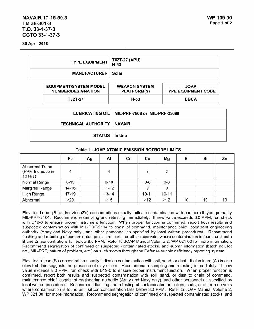
NAVAIR 17-15-50.3 TM 38-301-3 T.O. 33-1-37-3 CGTO 33-1-37-3
WP 139 00 Page 1 of 2
30 April 2018
TYPE EQUIPMENT T62T-27 (APU) H-53
MANUFACTURER Solar
EQUIPMENT/SYSTEM MODEL NUMBER/DESIGNATION
WEAPON SYSTEM PLATFORM(S)
JOAP TYPE EQUIPMENT CODE
T62T-27 H-53 DBCA
LUBRICATING OIL MIL-PRF-7808 or MIL-PRF-23699
TECHNICAL AUTHORITY NAVAIR
STATUS In Use
Table 1 - JOAP ATOMIC EMISSION ROTRODE LIMITS
Fe Ag Al Cr Cu Mg B Si Zn
Abnormal Trend (PPM Increase in 10 Hrs)
4 4 3 3
Normal Range 0-13 0-10 0-8 0-8 Marginal Range 14-16 11-12 9 9 High Range 17-19 13-14 10-11 10-11 Abnormal ≥20 ≥15 ≥12 ≥12 10 10 10
Elevated boron (B) and/or zinc (Zn) concentrations usually indicate contamination with another oil type, primarily MIL-PRF-2104. Recommend resampling and retesting immediately. If new value exceeds 8.0 PPM, run check with D19-0 to ensure proper instrument function. When proper function is confirmed, report both results and suspected contamination with MIL-PRF-2104 to chain of command, maintenance chief, cognizant engineering authority (Army and Navy only), and other personnel as specified by local written procedures. Recommend flushing and retesting of contaminated pre-oilers, carts, or other reservoirs where contamination is found until both B and Zn concentrations fall below 8.0 PPM. Refer to JOAP Manual Volume 2, WP 021 00 for more information. Recommend segregation of confirmed or suspected contaminated stocks, and submit information (batch no., lot no., MIL-PRF, nature of problem, etc.) on such stocks through the Defense supply deficiency reporting system.
Elevated silicon (Si) concentration usually indicates contamination with soil, sand, or dust. If aluminum (Al) is also elevated, this suggests the presence of clay or soil. Recommend resampling and retesting immediately. If new value exceeds 8.0 PPM, run check with D19-0 to ensure proper instrument function. When proper function is confirmed, report both results and suspected contamination with soil, sand, or dust to chain of command, maintenance chief, cognizant engineering authority (Army and Navy only), and other personnel as specified by local written procedures. Recommend flushing and retesting of contaminated pre-oilers, carts, or other reservoirs where contamination is found until silicon concentration falls below 8.0 PPM. Refer to JOAP Manual Volume 2, WP 021 00 for more information. Recommend segregation of confirmed or suspected contaminated stocks, and

NAVAIR 17-15-50.3 TM 38-301-3 T.O. 33-1-37-3 CGTO 33-1-37-3
WP 139 00 Page 2 of 2
30 April 2018
submit information (batch no., lot no., MIL-PRF, nature of problem, etc.) on such stocks through the Defense supply deficiency reporting system.
NOTE
The point of contact for this equipment is Graham Harlowe (Code 05311), DSN 993-7828 or FTS (510) 263-7828.

NAVAIR 17-15-50.3 TM 38-301-3 T.O. 33-1-37-3 CGTO 33-1-37-3
WP 140 00 Page 1 of 2
30 April 2018
TYPE EQUIPMENT T62T-40-1 (APU) VH-60N
MANUFACTURER Solar
EQUIPMENT/SYSTEM MODEL NUMBER/DESIGNATION
WEAPON SYSTEM PLATFORM(S)
JOAP TYPE EQUIPMENT CODE
T62T-40-1 VH-60N N/A
LUBRICATING OIL MIL-PRF-7808 or MIL-PRF-23699
TECHNICAL AUTHORITY NAVAIR
STATUS In Use
Table 1 - JOAP ATOMIC EMISSION ROTRODE LIMITS
Fe Ag Al Cr Cu Mg Mo B Si Zn
Abnormal Trend (PPM Increase in 10 Hrs)
3 2 2 2 2 9
Normal Range 0-6 0-2 0-2 0-2 0-2 0-30 Marginal Range 7 3 3 3 3 31-37 High Range 8-9 4 4 4 4 38-44 Abnormal ≥10 ≥5 ≥5 ≥5 ≥5 10 ≥45 10
Elevated boron (B) and/or zinc (Zn) concentrations usually indicate contamination with another oil type, primarily MIL-PRF-2104. Recommend resampling and retesting immediately. If new value exceeds 8.0 PPM, run check with D19-0 to ensure proper instrument function. When proper function is confirmed, report both results and suspected contamination with MIL-PRF-2104 to chain of command, maintenance chief, cognizant engineering authority (Army and Navy only), and other personnel as specified by local written procedures. Recommend flushing and retesting of contaminated pre-oilers, carts, or other reservoirs where contamination is found until both B and Zn concentrations fall below 8.0 PPM. Refer to JOAP Manual Volume 2, WP 021 00 for more information. Recommend segregation of confirmed or suspected contaminated stocks, and submit information (batch no., lot no., MIL-PRF, nature of problem, etc.) on such stocks through the Defense supply deficiency reporting system.
NOTES
Mg/Al - Magnesium and aluminum are usually observed wherever corrosion exists. However, when iron, magnesium, aluminum are present in abnormal concentrations, microscopic inspection of debris should be performed to determine whether metal is due to wear or corrosion.
Cr/Mo - Chromium and molybdenum should not be considered critical metals unless iron is present in abnormal concentrations.

NAVAIR 17-15-50.3 TM 38-301-3 T.O. 33-1-37-3 CGTO 33-1-37-3
WP 140 00 Page 2 of 2
30 April 2018
This Page Intentionally Left Blank

NAVAIR 17-15-50.3 TM 38-301-3 T.O. 33-1-37-3 CGTO 33-1-37-3
WP 141 00 Page 1 of 2
30 April 2018
TYPE EQUIPMENT GTC85 GROUND SUPPORT EQUIPMENT (NAVY)
MANUFACTURER Honeywell Garrett
EQUIPMENT/SYSTEM MODEL NUMBER/DESIGNATION
WEAPON SYSTEM PLATFORM(S)
JOAP TYPE EQUIPMENT CODE
GTC85 GSE N/A
LUBRICATING OIL MIL-PRF-23699
TECHNICAL AUTHORITY NAVAIR
STATUS In Use
Table 1 - JOAP ATOMIC EMISSION ROTRODE LIMITS
Fe Ag Al Cr Cu Mg B Si Zn
Abnormal Trend (PPM Increase in 10 Hrs)
3 3 3 3
Normal Range 0-8 0-6 0-7 0-6 Marginal Range 9 7 8 7 High Range 10-11 8-9 9-10 8-9 Abnormal ≥12 ≥10 ≥11 ≥10 10 10 10
Elevated boron (B) and/or zinc (Zn) concentrations usually indicate contamination with another oil type, primarily MIL-PRF-2104. Recommend resampling and retesting immediately. If new value exceeds 8.0 PPM, run check with D19-0 to ensure proper instrument function. When proper function is confirmed, report both results and suspected contamination with MIL-PRF-2104 to chain of command, maintenance chief, cognizant engineering authority (Army and Navy only), and other personnel as specified by local written procedures. Recommend flushing and retesting of contaminated pre-oilers, carts, or other reservoirs where contamination is found until both B and Zn concentrations fall below 8.0 PPM. Refer to JOAP Manual Volume 2, WP 021 00 for more information. Recommend segregation of confirmed or suspected contaminated stocks, and submit information (batch no., lot no., MIL-PRF, nature of problem, etc.) on such stocks through the Defense supply deficiency reporting system.
Elevated silicon (Si) concentration usually indicates contamination with soil, sand, or dust. If aluminum (Al) is also elevated, this suggests the presence of clay or soil. Recommend resampling and retesting immediately. If new value exceeds 8.0 PPM, run check with D19-0 to ensure proper instrument function. When proper function is confirmed, report both results and suspected contamination with soil, sand, or dust to chain of command, maintenance chief, cognizant engineering authority (Army and Navy only), and other personnel as specified by local written procedures. Recommend flushing and retesting of contaminated pre-oilers, carts, or other reservoirs where contamination is found until silicon concentration falls below 8.0 PPM. Refer to JOAP Manual Volume 2, WP 021 00 for more information. Recommend segregation of confirmed or suspected contaminated stocks, and

NAVAIR 17-15-50.3 TM 38-301-3 T.O. 33-1-37-3 CGTO 33-1-37-3
WP 141 00 Page 2 of 2
30 April 2018
submit information (batch no., lot no., MIL-PRF, nature of problem, etc.) on such stocks through the Defense supply deficiency reporting system.

NAVAIR 17-15-50.3 TM 38-301-3 T.O. 33-1-37-3 CGTO 33-1-37-3
WP 142 00 Page 1 of 2
30 April 2018
TYPE EQUIPMENT GTC85-180 M32A-60
MANUFACTURER Honeywell Garrett
EQUIPMENT/SYSTEM MODEL NUMBER/DESIGNATION
WEAPON SYSTEM PLATFORM(S)
JOAP TYPE EQUIPMENT CODE
GTCP 85-180 M32A-60 DJBB
LUBRICATING OIL MIL-PRF-23699 or MIL-PRF-7808
TECHNICAL AUTHORITY Air Force
STATUS In Use
Table 1 - JOAP ATOMIC EMISSION ROTRODE LIMITS
*Fe Ag Al Cr *Cu Mg B Si Zn
Abnormal Trend (PPM Increase in 10 Hrs)
9 2 4 2 4 3
Normal Range 0-29 0-2 0-10 0-4 0-13 0-6 Marginal Range 30-36 N/A 11-12 5 14-16 7 High Range 37-44 3 13-14 6 17-19 8-9 Abnormal ≥45 ≥4 ≥15 ≥7 ≥20 ≥10 10 10 10 NOTE: * Increase in Fe and Cu indicates discrepancy in starter clutch area.
Elevated boron (B) and/or zinc (Zn) concentrations usually indicate contamination with another oil type, primarily MIL-PRF-2104. Recommend resampling and retesting immediately. If new value exceeds 8.0 PPM, run check with D19-0 to ensure proper instrument function. When proper function is confirmed, report both results and suspected contamination with MIL-PRF-2104 to chain of command, maintenance chief, cognizant engineering authority (Army and Navy only), and other personnel as specified by local written procedures. Recommend flushing and retesting of contaminated pre-oilers, carts, or other reservoirs where contamination is found until both B and Zn concentrations fall below 8.0 PPM. Refer to JOAP Manual Volume 2, WP 021 00 for more information. Recommend segregation of confirmed or suspected contaminated stocks, and submit information (batch no., lot no., MIL-PRF, nature of problem, etc.) on such stocks through the Defense supply deficiency reporting system.
Elevated silicon (Si) concentration usually indicates contamination with soil, sand, or dust. If aluminum (Al) is also elevated, this suggests the presence of clay or soil. Recommend resampling and retesting immediately. If new value exceeds 8.0 PPM, run check with D19-0 to ensure proper instrument function. When proper function is confirmed, report both results and suspected contamination with soil, sand, or dust to chain of command, maintenance chief, cognizant engineering authority (Army and Navy only), and other personnel as specified by local written procedures. Recommend flushing and retesting of contaminated pre-oilers, carts, or other reservoirs

NAVAIR 17-15-50.3 TM 38-301-3 T.O. 33-1-37-3 CGTO 33-1-37-3
WP 142 00 Page 2 of 2
30 April 2018
where contamination is found until silicon concentration falls below 8.0 PPM. Refer to JOAP Manual Volume 2, WP 021 00 for more information. Recommend segregation of confirmed or suspected contaminated stocks, and submit information (batch no., lot no., MIL-PRF, nature of problem, etc.) on such stocks through the Defense supply deficiency reporting system.

NAVAIR 17-15-50.3 TM 38-301-3 T.O. 33-1-37-3 CGTO 33-1-37-3
WP 143 00 Page 1 of 2
30 April 2018
TYPE EQUIPMENT GTCP85-397 M32A-60
MANUFACTURER Honeywell Garrett
EQUIPMENT/SYSTEM MODEL NUMBER/DESIGNATION
WEAPON SYSTEM PLATFORM(S)
JOAP TYPE EQUIPMENT CODE
GTCP 85-397 M32A-60 DJCA
LUBRICATING OIL MIL-PRF-23699 or MIL-PRF-7808
TECHNICAL AUTHORITY Air Force
STATUS In Use
Table 1 - JOAP ATOMIC EMISSION ROTRODE LIMITS
*Fe Ag Al Cr *Cu Mg B Si Zn
Abnormal Trend (PPM Increase in 10 Hrs)
11 2 4 3 4 3
Normal Range 0-36 0-5 0-10 0-8 0-13 0-8 Marginal Range 37-44 6 11-12 9 14-16 9 High Range 45-54 7 13-14 10-11 17-19 10-11 Abnormal ≥55 ≥8 ≥15 ≥12 ≥20 ≥12 10 10 10 NOTE: * Increase in Fe and Cu indicates discrepancy in bearing area.
Elevated boron (B) and/or zinc (Zn) concentrations usually indicate contamination with another oil type, primarily MIL-PRF-2104. Recommend resampling and retesting immediately. If new value exceeds 8.0 PPM, run check with D19-0 to ensure proper instrument function. When proper function is confirmed, report both results and suspected contamination with MIL-PRF-2104 to chain of command, maintenance chief, cognizant engineering authority (Army and Navy only), and other personnel as specified by local written procedures. Recommend flushing and retesting of contaminated pre-oilers, carts, or other reservoirs where contamination is found until both B and Zn concentrations fall below 8.0 PPM. Refer to JOAP Manual Volume 2, WP 021 00 for more information. Recommend segregation of confirmed or suspected contaminated stocks, and submit information (batch no., lot no., MIL-PRF, nature of problem, etc.) on such stocks through the Defense supply deficiency reporting system.
Elevated silicon (Si) concentration usually indicates contamination with soil, sand, or dust. If aluminum (Al) is also elevated, this suggests the presence of clay or soil. Recommend resampling and retesting immediately. If new value exceeds 8.0 PPM, run check with D19-0 to ensure proper instrument function. When proper function is confirmed, report both results and suspected contamination with soil, sand, or dust to chain of command, maintenance chief, cognizant engineering authority (Army and Navy only), and other personnel as specified by local written procedures. Recommend flushing and retesting of contaminated pre-oilers, carts, or other reservoirs

NAVAIR 17-15-50.3 TM 38-301-3 T.O. 33-1-37-3 CGTO 33-1-37-3
WP 143 00 Page 2 of 2
30 April 2018
where contamination is found until silicon concentration falls below 8.0 PPM. Refer to JOAP Manual Volume 2, WP 021 00 for more information. Recommend segregation of confirmed or suspected contaminated stocks, and submit information (batch no., lot no., MIL-PRF, nature of problem, etc.) on such stocks through the Defense supply deficiency reporting system.
Fe & Cr Bearing rollers and races
Fe & Ni Oil pump gears and shaft
Fe & Cr Ni Turbine and aft compressor carbon seal races Turbine section bearing spacer and housing Aft compressor section shaft and bearing mount Accessory assembly carbon seal rotors, gears, shafts, bearing housing, retainers and carriers Output geardrive seal runners and bearing retainer gasket seals Forward compressor assembly shaft and inlet compressor seal races
Cu Oil pump bushings
Cu & Ag Turbine section bearing cages
Cu & Sn Output geardrive bearing cages Aft compressor section bearing cages Oil pump gear pins
Cu & Ag Sn Accessory assembly bearing cages
Al & Cu Forward compressor assembly bearing and seal housing Oil pump body, cover and plate assembly
Mg Accessory case assembly
Al & Mg Output geardrive housing
Al & Ni Cr Output geardrive gears
Ni & Cr Fe Turbine wheel shaft
Sn & Fe Cu Forward compressor assembly sleeve bearing

NAVAIR 17-15-50.3 TM 38-301-3 T.O. 33-1-37-3 CGTO 33-1-37-3
WP 144 00 Page 1 of 2
30 April 2018
TYPE EQUIPMENT GTCP100 GROUND SUPPORT EQUIPMENT (NAVY)
MANUFACTURER Honeywell Garrett
EQUIPMENT/SYSTEM MODEL NUMBER/DESIGNATION
WEAPON SYSTEM PLATFORM(S)
JOAP TYPE EQUIPMENT CODE
GTCP 100 GSE N/A
LUBRICATING OIL MIL-PRF-23699 or MIL-PRF-7808
TECHNICAL AUTHORITY NAVAIR
STATUS In Use
Table 1 - JOAP ATOMIC EMISSION ROTRODE LIMITS
Fe Ag Al Cr Cu Mg B Si Zn
Abnormal Trend (PPM Increase in 10 Hrs)
4 3
Normal Range 0-13 0-7 Marginal Range 14-16 8 High Range 17-19 9-10 Abnormal ≥20 ≥11 10 10 10
Elevated boron (B) and/or zinc (Zn) concentrations usually indicate contamination with another oil type, primarily MIL-PRF-2104. Recommend resampling and retesting immediately. If new value exceeds 8.0 PPM, run check with D19-0 to ensure proper instrument function. When proper function is confirmed, report both results and suspected contamination with MIL-PRF-2104 to chain of command, maintenance chief, cognizant engineering authority (Army and Navy only), and other personnel as specified by local written procedures. Recommend flushing and retesting of contaminated pre-oilers, carts, or other reservoirs where contamination is found until both B and Zn concentrations fall below 8.0 PPM. Refer to JOAP Manual Volume 2, WP 021 00 for more information. Recommend segregation of confirmed or suspected contaminated stocks, and submit information (batch no., lot no., MIL-PRF, nature of problem, etc.) on such stocks through the Defense supply deficiency reporting system.
Elevated silicon (Si) concentration usually indicates contamination with soil, sand, or dust. If aluminum (Al) is also elevated, this suggests the presence of clay or soil. Recommend resampling and retesting immediately. If new value exceeds 8.0 PPM, run check with D19-0 to ensure proper instrument function. When proper function is confirmed, report both results and suspected contamination with soil, sand, or dust to chain of command, maintenance chief, cognizant engineering authority (Army and Navy only), and other personnel as specified by local written procedures. Recommend flushing and retesting of contaminated pre-oilers, carts, or other reservoirs where contamination is found until silicon concentration falls below 8.0 PPM. Refer JOAP Manual Volume 2, WP 021 00 for more information. Recommend segregation of confirmed or suspected contaminated stocks, and

NAVAIR 17-15-50.3 TM 38-301-3 T.O. 33-1-37-3 CGTO 33-1-37-3
WP 144 00 Page 2 of 2
30 April 2018
submit information (batch no., lot no., MIL-PRF, nature of problem, etc.) on such stocks through the Defense supply deficiency reporting system.

NAVAIR 17-15-50.3 TM 38-301-3 T.O. 33-1-37-3 CGTO 33-1-37-3
WP 145 00 Page 1 of 2
30 April 2018
TYPE EQUIPMENT T62T-32 EMU-30, EMU-36
MANUFACTURER Solar
EQUIPMENT/SYSTEM MODEL NUMBER/DESIGNATION
WEAPON SYSTEM PLATFORM(S)
JOAP TYPE EQUIPMENT CODE
T62T-32 EMU-30 DBDA
T62T-32 EMU-36 DBDB
LUBRICATING OIL MIL-PRF-23699 or MIL-PRF-7808
TECHNICAL AUTHORITY Army
STATUS In Use
Table 1 - JOAP ATOMIC EMISSION ROTRODE LIMITS
Fe Ag Al Cr Cu Mg B Si Zn
Abnormal Trend (PPM Increase in 10 Hrs)
4 2 2 2 3 3
Normal Range 0-13 0-3 0-3 0-3 0-8 0-8 Marginal Range 14-16 N/A 4 N/A 9 9 High Range 17-19 4 5 4 10-11 10-11 Abnormal ≥20 ≥5 ≥6 ≥5 ≥12 ≥12 10 10 10
Elevated boron (B) and/or zinc (Zn) concentrations usually indicate contamination with another oil type, primarily MIL-PRF-2104. Recommend resampling and retesting immediately. If new value exceeds 8.0 PPM, run check with D19-0 to ensure proper instrument function. When proper function is confirmed, report both results and suspected contamination with MIL-PRF-2104 to chain of command, maintenance chief, cognizant engineering authority (Army and Navy only), and other personnel as specified by local written procedures. Recommend flushing and retesting of contaminated pre-oilers, carts, or other reservoirs where contamination is found until both B and Zn concentrations fall below 8.0 PPM. Refer to JOAP Manual Volume 2, WP 021 00 for more information. Recommend segregation of confirmed or suspected contaminated stocks, and submit information (batch no., lot no., MIL-PRF, nature of problem, etc.) on such stocks through the Defense supply deficiency reporting system.
Elevated silicon (Si) concentration usually indicates contamination with soil, sand, or dust. If aluminum (Al) is also elevated, this suggests the presence of clay or soil. Recommend resampling and retesting immediately. If new value exceeds 8.0 PPM, run check with D19-0 to ensure proper instrument function. When proper function is confirmed, report both results and suspected contamination with soil, sand, or dust to chain of command, maintenance chief, cognizant engineering authority (Army and Navy only), and other personnel as specified by local written procedures. Recommend flushing and retesting of contaminated pre-oilers, carts, or other reservoirs

NAVAIR 17-15-50.3 TM 38-301-3 T.O. 33-1-37-3 CGTO 33-1-37-3
WP 145 00 Page 2 of 2
30 April 2018
where contamination is found until silicon concentration falls below 8.0 PPM. Refer to JOAP Manual Volume 2, WP 021 00 for more information. Recommend segregation of confirmed or suspected contaminated stocks, and submit information (batch no., lot no., MIL-PRF, nature of problem, etc.) on such stocks through the Defense supply deficiency reporting system.
Fe Oil pump gears
Fe Cr Bearing balls, rollers and races
Fe Ni Accessory drive gears, compressor shaft
Fe Ni & Cr Accessory drive planet gear, accessory drive main gear, compressor-to-turbine seal
Mg Al & Zn Reduction drive assembly housings, reduction drive housing cover
Al Cu Mg & Si Compressor housing, oil pump housings
Cu Si Zn Fe Ag Turbine section bearing cages
Al Mg Reduction drive bearing cages

NAVAIR 17-15-50.3 TM 38-301-3 T.O. 33-1-37-3 CGTO 33-1-37-3
WP 146 00 Page 1 of 2
30 April 2018
TYPE EQUIPMENT A-4F/M CONSTANT SPEED DRIVE (NAVY)
MANUFACTURER Sundstrand
EQUIPMENT/SYSTEM MODEL NUMBER/DESIGNATION
WEAPON SYSTEM PLATFORM(S)
JOAP TYPE EQUIPMENT CODE
CSD A-4F/M DSAA
LUBRICATING OIL MIL-PRF-23699 or MIL-PRF-7808
TECHNICAL AUTHORITY NAVAIR
STATUS Aircraft and CSD Retired. WP retained for reference.
Table 1 - JOAP ATOMIC EMISSION ROTRODE LIMITS
Fe Ag Al Cr Cu Mg B Si Zn
Abnormal Trend (PPM Increase in 10 Hrs)
17 6
Normal Range 0-56 0-20 Marginal Range 57-68 21-25 High Range 69-84 26-29 Abnormal ≥85 ≥30 10 10 10
Elevated boron (B) and/or zinc (Zn) concentrations usually indicate contamination with another oil type, primarily MIL-PRF-2104. Recommend resampling and retesting immediately. If new value exceeds 8.0 PPM, run check with D19-0 to ensure proper instrument function. When proper function is confirmed, report both results and suspected contamination with MIL-PRF-2104 to chain of command, maintenance chief, cognizant engineering authority (Army and Navy only), and other personnel as specified by local written procedures. Recommend flushing and retesting of contaminated pre-oilers, carts, or other reservoirs where contamination is found until both B and Zn concentrations fall below 8.0 PPM. Refer to JOAP Manual Volume 2, WP 021 00 for more information. Recommend segregation of confirmed or suspected contaminated stocks, and submit information (batch no., lot no., MIL-PRF, nature of problem, etc.) on such stocks through the Defense supply deficiency reporting system.
Elevated silicon (Si) concentration usually indicates contamination with soil, sand, or dust. If aluminum (Al) is also elevated, this suggests the presence of clay or soil. Recommend resampling and retesting immediately. If new value exceeds 8.0 PPM, run check with D19-0 to ensure proper instrument function. When proper function is confirmed, report both results and suspected contamination with soil, sand, or dust to chain of command, maintenance chief, cognizant engineering authority (Army and Navy only), and other personnel as specified by local written procedures. Recommend flushing and retesting of contaminated pre-oilers, carts, or other reservoirs where contamination is found until silicon concentration falls below 8.0 PPM. Refer to JOAP Manual Volume 2,

NAVAIR 17-15-50.3 TM 38-301-3 T.O. 33-1-37-3 CGTO 33-1-37-3
WP 146 00 Page 2 of 2
30 April 2018
WP 021 00 for more information. Recommend segregation of confirmed or suspected contaminated stocks, and submit information (batch no., lot no., MIL-PRF, nature of problem, etc.) on such stocks through the Defense supply deficiency reporting system.

NAVAIR 17-15-50.3 TM 38-301-3 T.O. 33-1-37-3 CGTO 33-1-37-3
WP 147 00 Page 1 of 2
30 April 2018
TYPE EQUIPMENT EA-6B CONSTANT SPEED DRIVE (NAVY)
MANUFACTURER Sundstrand
EQUIPMENT/SYSTEM MODEL NUMBER/DESIGNATION
WEAPON SYSTEM PLATFORM(S)
JOAP TYPE EQUIPMENT CODE
CSD EA-6B DSBA
LUBRICATING OIL MIL-PRF-23699 or MIL-PRF-7808
TECHNICAL AUTHORITY NAVAIR
STATUS In Use
Table 1 - JOAP ATOMIC EMISSION ROTRODE LIMITS
Fe Ag Al Cr Cu Mg B Si Zn
Abnormal Trend (PPM Increase in 10 Hrs)
4 4 6 4
Normal Range 0-12 0-12 0-25 0-13 Marginal Range 13-15 13-15 26-31 14-16 High Range 16-17 16-17 32-38 17-19 Abnormal ≥18 ≥18 ≥39 ≥20 10 10 10
Elevated boron (B) and/or zinc (Zn) concentrations usually indicate contamination with another oil type, primarily MIL-PRF-2104. Recommend resampling and retesting immediately. If new value exceeds 8.0 PPM, run check with D19-0 to ensure proper instrument function. When proper function is confirmed, report both results and suspected contamination with MIL-PRF-2104 to chain of command, maintenance chief, cognizant engineering authority (Army and Navy only), and other personnel as specified by local written procedures. Recommend flushing and retesting of contaminated pre-oilers, carts, or other reservoirs where contamination is found until both B and Zn concentrations fall below 8.0 PPM. Refer to JOAP Manual Volume 2, WP 021 00 for more information. Recommend segregation of confirmed or suspected contaminated stocks, and submit information (batch no., lot no., MIL-PRF, nature of problem, etc.) on such stocks through the Defense supply deficiency reporting system.
Elevated silicon (Si) concentration usually indicates contamination with soil, sand, or dust. If aluminum (Al) is also elevated, this suggests the presence of clay or soil. Recommend resampling and retesting immediately. If new value exceeds 8.0 PPM, run check with D19-0 to ensure proper instrument function. When proper function is confirmed, report both results and suspected contamination with soil, sand, or dust to chain of command, maintenance chief, cognizant engineering authority (Army and Navy only), and other personnel as specified by local written procedures. Recommend flushing and retesting of contaminated pre-oilers, carts, or other reservoirs where contamination is found until silicon concentration falls below 8.0 PPM. Refer to JOAP Manual Volume 2, WP 021 00 for more information. Recommend segregation of confirmed or suspected contaminated stocks, and

NAVAIR 17-15-50.3 TM 38-301-3 T.O. 33-1-37-3 CGTO 33-1-37-3
WP 147 00 Page 2 of 2
30 April 2018
submit information (batch no., lot no., MIL-PRF, nature of problem, etc.) on such stocks through the Defense supply deficiency reporting system.

NAVAIR 17-15-50.3 TM 38-301-3 T.O. 33-1-37-3 CGTO 33-1-37-3
WP 148 00 Page 1 of 2
30 April 2018
TYPE EQUIPMENT AV-8A, TAV-8A INTEGRATED DRIVE (NAVY)
MANUFACTURER UTC Aerospace - Sundstrand
EQUIPMENT/SYSTEM MODEL NUMBER/DESIGNATION
WEAPON SYSTEM PLATFORM(S)
JOAP TYPE EQUIPMENT CODE
ING DR GEN AV-8A, TAV-8A DPAA
LUBRICATING OIL MIL-PRF-23699 or MIL-PRF-7808
TECHNICAL AUTHORITY NAVAIR
STATUS Component Retired. WP retained for reference.
Table 1 - JOAP ATOMIC EMISSION ROTRODE LIMITS
Fe Ag Al Cr Cu Mg B Si Zn
Abnormal Trend (PPM Increase in 10 Hrs)
7 4 3 4 4
Normal Range 0-24 0-13 0-6 0-11 0-10 Marginal Range 25-29 14-16 7 12-13 11-12 High Range 30-36 17-19 8-9 14-16 13-14 Abnormal ≥37 ≥20 ≥10 ≥17 ≥15 10 10 10
Elevated boron (B) and/or zinc (Zn) concentrations usually indicate contamination with another oil type, primarily MIL-PRF-2104. Recommend resampling and retesting immediately. If new value exceeds 8.0 PPM, run check with D19-0 to ensure proper instrument function. When proper function is confirmed, report both results and suspected contamination with MIL-PRF-2104 to chain of command, maintenance chief, cognizant engineering authority (Army and Navy only), and other personnel as specified by local written procedures. Recommend flushing and retesting of contaminated pre-oilers, carts, or other reservoirs where contamination is found until both B and Zn concentrations fall below 8.0 PPM. Refer to JOAP Manual Volume 2, WP 021 00 for more information. Recommend segregation of confirmed or suspected contaminated stocks, and submit information (batch no., lot no., MIL-PRF, nature of problem, etc.) on such stocks through the Defense supply deficiency reporting system.
Elevated silicon (Si) concentration usually indicates contamination with soil, sand, or dust. If aluminum (Al) is also elevated, this suggests the presence of clay or soil. Recommend resampling and retesting immediately. If new value exceeds 8.0 PPM, run check with D19-0 to ensure proper instrument function. When proper function is confirmed, report both results and suspected contamination with soil, sand, or dust to chain of command, maintenance chief, cognizant engineering authority (Army and Navy only), and other personnel as specified by local written procedures. Recommend flushing and retesting of contaminated pre-oilers, carts, or other reservoirs where contamination is found until silicon concentration falls below 8.0 PPM. Refer to JOAP Manual Volume 2, WP 021 00 for more information. Recommend segregation of confirmed or suspected contaminated stocks, and

NAVAIR 17-15-50.3 TM 38-301-3 T.O. 33-1-37-3 CGTO 33-1-37-3
WP 148 00 Page 2 of 2
30 April 2018
submit information (batch no., lot no., MIL-PRF, nature of problem, etc.) on such stocks through the Defense supply deficiency reporting system.

NAVAIR 17-15-50.3 TM 38-301-3 T.O. 33-1-37-3 CGTO 33-1-37-3
WP 149 00 Page 1 of 2
30 April 2018
TYPE EQUIPMENT F-14 CONSTANT SPEED DRIVE (NAVY)
MANUFACTURER UTC Aerospace - Sundstrand
EQUIPMENT/SYSTEM MODEL NUMBER/DESIGNATION
WEAPON SYSTEM PLATFORM(S)
JOAP TYPE EQUIPMENT CODE
CSD F-14 DSEA
LUBRICATING OIL MIL-PRF-23699 or MIL-PRF-7808
TECHNICAL AUTHORITY NAVAIR
STATUS Aircraft and CSD retired. WP retained for reference.
Table 1 - JOAP ATOMIC EMISSION ROTRODE LIMITS
Fe Ag Al Cr Cu Mg B Si Zn
Abnormal Trend (PPM Increase in 10 Hrs)
4 4
Normal Range 0-14 0-13 Marginal Range 15-17 14-16 High Range 18-21 17-19 Abnormal ≥22 ≥20 10 10 10
Elevated boron (B) and/or zinc (Zn) concentrations usually indicate contamination with another oil type, primarily MIL-PRF-2104. Recommend resampling and retesting immediately. If new value exceeds 8.0 PPM, run check with D19-0 to ensure proper instrument function. When proper function is confirmed, report both results and suspected contamination with MIL-PRF-2104 to chain of command, maintenance chief, cognizant engineering authority (Army and Navy only), and other personnel as specified by local written procedures. Recommend flushing and retesting of contaminated pre-oilers, carts, or other reservoirs where contamination is found until both B and Zn concentrations fall below 8.0 PPM. Refer to JOAP Manual Volume 2, WP 021 00 for more information. Recommend segregation of confirmed or suspected contaminated stocks, and submit information (batch no., lot no., MIL-PRF, nature of problem, etc.) on such stocks through the Defense supply deficiency reporting system.
Elevated silicon (Si) concentration usually indicates contamination with soil, sand, or dust. If aluminum (Al) is also elevated, this suggests the presence of clay or soil. Recommend resampling and retesting immediately. If new value exceeds 8.0 PPM, run check with D19-0 to ensure proper instrument function. When proper function is confirmed, report both results and suspected contamination with soil, sand, or dust to chain of command, maintenance chief, cognizant engineering authority (Army and Navy only), and other personnel as specified by local written procedures. Recommend flushing and retesting of contaminated pre-oilers, carts, or other reservoirs where contamination is found until silicon concentration falls below 8.0 PPM. Refer to JOAP Manual Volume 2, WP 021 00 for more information. Recommend segregation of confirmed or suspected contaminated stocks, and

NAVAIR 17-15-50.3 TM 38-301-3 T.O. 33-1-37-3 CGTO 33-1-37-3
WP 149 00 Page 2 of 2
30 April 2018
submit information (batch no., lot no., MIL-PRF, nature of problem, etc.) on such stocks through the Defense supply deficiency reporting system.

NAVAIR 17-15-50.3 TM 38-301-3 T.O. 33-1-37-3 CGTO 33-1-37-3
WP 150 00 Page 1 of 2
30 April 2018
TYPE EQUIPMENT S-3 INTEGRATED DRIVE GENERATOR (NAVY)
MANUFACTURER UTC Aerospace - Sundstrand
EQUIPMENT/SYSTEM MODEL NUMBER/DESIGNATION
WEAPON SYSTEM PLATFORM(S)
JOAP TYPE EQUIPMENT CODE
INT DR GEN S-3 N/A
LUBRICATING OIL MIL-PRF-23699 or MIL-PRF-7808
TECHNICAL AUTHORITY NAVAIR
STATUS Aircraft and CSD retired. WP retained for reference.
Table 1 - JOAP ATOMIC EMISSION ROTRODE LIMITS
Fe Ag Al Cr Cu *Mg B Si Zn
Abnormal Trend (PPM Increase in 10 Hrs)
15 3 11 20
Normal Range 0-48 0-8 *0-29 0-64 Marginal Range 49-54 9 30-35 65-80 High Range 55-72 10-11 36-43 81-99 Abnormal ≥73 ≥12 ≥44 ≥100 10 10 10 NOTE: * If Mg is 30 PPM or above and confirmed by repeat (Check Sample), recommend Code J
Elevated boron (B) and/or zinc (Zn) concentrations usually indicate contamination with another oil type, primarily MIL-PRF-2104. Recommend resampling and retesting immediately. If new value exceeds 8.0 PPM, run check with D19-0 to ensure proper instrument function. When proper function is confirmed, report both results and suspected contamination with MIL-PRF-2104 to chain of command, maintenance chief, cognizant engineering authority (Army and Navy only), and other personnel as specified by local written procedures. Recommend flushing and retesting of contaminated pre-oilers, carts, or other reservoirs where contamination is found until both B and Zn concentrations fall below 8.0 PPM. Refer to JOAP Manual Volume 2, WP 021 00 for more information. Recommend segregation of confirmed or suspected contaminated stocks, and submit information (batch no., lot no., MIL-PRF, nature of problem, etc.) on such stocks through the Defense supply deficiency reporting system.
Elevated silicon (Si) concentration usually indicates contamination with soil, sand, or dust. If aluminum (Al) is also elevated, this suggests the presence of clay or soil. Recommend resampling and retesting immediately. If new value exceeds 8.0 PPM, run check with D19-0 to ensure proper instrument function. When proper function is confirmed, report both results and suspected contamination with soil, sand, or dust to chain of command, maintenance chief, cognizant engineering authority (Army and Navy only), and other personnel as specified by local written procedures. Recommend flushing and retesting of contaminated pre-oilers, carts, or other reservoirs

NAVAIR 17-15-50.3 TM 38-301-3 T.O. 33-1-37-3 CGTO 33-1-37-3
WP 150 00 Page 2 of 2
30 April 2018
where contamination is found until silicon concentration falls below 8.0 PPM. Refer to JOAP Manual Volume 2, WP 021 00 for more information. Recommend segregation of confirmed or suspected contaminated stocks, and submit information (batch no., lot no., MIL-PRF, nature of problem, etc.) on such stocks through the Defense supply deficiency reporting system.

NAVAIR 17-15-50.3 TM 38-301-3 T.O. 33-1-37-3 CGTO 33-1-37-3
WP 151 00 Page 1 of 2
30 April 2018
TYPE EQUIPMENT HYDRAULIC SYSTEMS (ARMY AND AIR FORCE) H-1 (ALL SERIES)
MANUFACTURER Bell Boeing
EQUIPMENT/SYSTEM MODEL NUMBER/DESIGNATION
WEAPON SYSTEM PLATFORM(S)
JOAP TYPE EQUIPMENT CODE
Hyd Sys UH-1B HAAB
Hyd Sys UH-1C HAAC
Hyd Pump UH-1FS HAA1
Hyd Sys UH-1H HAAH
Hyd Sys 1 UH-1M HA1M
Hyd Sys 2 UH-1M HA2M
Hyd Sys UH-1N HAA4
Hyd Sys UH-1V HAAV
Hyd Sys UH-1X HAAX
LUBRICATING OIL MIL-PRF-83282, MIL-PRF-87257 or MIL-PRF-5606
TECHNICAL AUTHORITY Army
STATUS In Use
Table 1 - JOAP ATOMIC EMISSION ROTRODE LIMITS
Fe Ag Al Cr Cu Mg B Si Zn
Abnormal Trend (PPM Increase in 10 Hrs)
4 7 2 4 4 9
Normal Range 0-13 0-25 0-5 0-12 0-14 0-30 Marginal Range 14-16 26-31 6 13-14 15-17 31-37 High Range 17-20 32-38 7 15-18 18-21 38-44 Abnormal ≥21 ≥39 ≥8 ≥19 ≥22 10 ≥45 10
Elevated boron (B) and/or zinc (Zn) concentrations usually indicate contamination with another oil type, primarily MIL-PRF-2104. Recommend resampling and retesting immediately. If new value exceeds 8.0 PPM, run check with D19-0 to ensure proper instrument function. When proper function is confirmed, report both results and

NAVAIR 17-15-50.3 TM 38-301-3 T.O. 33-1-37-3 CGTO 33-1-37-3
WP 151 00 Page 2 of 2
30 April 2018
suspected contamination with MIL-PRF-2104 to chain of command, maintenance chief, cognizant engineering authority (Army and Navy only), and other personnel as specified by local written procedures. Recommend flushing and retesting of contaminated pre-oilers, carts, or other reservoirs where contamination is found until both B and Zn concentrations fall below 8.0 PPM. Refer to JOAP Manual Volume 2, WP 021 00 for more information. Recommend segregation of confirmed or suspected contaminated stocks, and submit information (batch no., lot no., MIL-PRF, nature of problem, etc.) on such stocks through the Defense supply deficiency reporting system.
Fe Pump piston shoe plate and bearing assemblies
Fe & Cu Pump piston cylinder body
Al Servo cylinder walls
Al & Si Servo cylinder body and seals
Mg Pump bearing liners
NOTES
1. High concentration of Fe and Mg accompanied by a chalky color in the fluid's appearance normally indicates moisture and system corrosion.
2. High concentration of Al and Si may also indicate contamination from ground test unit.

NAVAIR 17-15-50.3 TM 38-301-3 T.O. 33-1-37-3 CGTO 33-1-37-3
WP 152 00 Page 1 of 4
30 April 2018
TYPE EQUIPMENT HYDRAULIC SYSTEMS (ARMY) CH-47 MH-47 (ALL SERIES)
MANUFACTURER Bell Boeing
EQUIPMENT/SYSTEM MODEL NUMBER/DESIGNATION
WEAPON SYSTEM PLATFORM(S)
JOAP TYPE EQUIPMENT CODE
Hyd Sys 1 CH-47A HE1A
Hyd Sys 2 CH-47A HE2A
Hyd Sys 3 CH-47A HE3A
Hyd Sys 1 CH-47B HE1B
Hyd Sys 2 CH-47B HE2B
Hyd Sys 3 CH-47B HE3B
Hyd Sys 1 CH-47C HE1C
Hyd Sys 2 CH-47C HE2C
Hyd Sys 3 CH-47C HE3C
Hyd Sys 1 CH-47D HE1D
Hyd Sys 2 CH-47D HE2D
Hyd Sys 3 CH-47D HE3D
Hyd Sys 1 CH-47F HE1F
Hyd Sys 2 CH-47F HE2F
Hyd Sys 3 CH-47F HE3F
Hyd Sys 1 MH-47D HE1G
Hyd Sys 2 MH-47D HE2G
Hyd Sys 3 MH-47D HE3G
Hyd Sys 1 MH-47E HE1E
Hyd Sys 2 MH-47E HE2E
Hyd Sys 3 MH-47E HE3E
Hyd Sys 1 MH-47G HE1H

NAVAIR 17-15-50.3 TM 38-301-3 T.O. 33-1-37-3 CGTO 33-1-37-3
WP 152 00 Page 2 of 4
30 April 2018
EQUIPMENT/SYSTEM MODEL NUMBER/DESIGNATION
WEAPON SYSTEM PLATFORM(S)
JOAP TYPE EQUIPMENT CODE
Hyd Sys 2 MH-47G HE2H
Hyd Sys 3 MH-47G HE3H
LUBRICATING OIL MIL-PRF-83282, MIL-PRF-87257 or MIL-PRF-5606
TECHNICAL AUTHORITY Army
STATUS In Use
Table 1 - JOAP ATOMIC EMISSION ROTRODE LIMITS
Fe Ag Al Cr Cu Mg B Si Zn
Abnormal Trend (PPM Increase in 10 Hrs)
4 4 4 5 4 5
Normal Range 0-15 0-14 0-13 0-18 0-15 0-19 Marginal Range 16-18 15-17 14-16 19-22 16-18 20-23 High Range 19-23 18-21 17-20 23-26 19-23 24-28 Abnormal ≥24 ≥22 ≥21 ≥27 ≥24 10 ≥29 10
Elevated boron (B) and/or zinc (Zn) concentrations usually indicate contamination with another oil type, primarily MIL-PRF-2104. Recommend resampling and retesting immediately. If new value exceeds 8.0 PPM, run check with D19-0 to ensure proper instrument function. When proper function is confirmed, report both results and suspected contamination with MIL-PRF-2104 to chain of command, maintenance chief, cognizant engineering authority (Army and Navy only), and other personnel as specified by local written procedures. Recommend flushing and retesting of contaminated pre-oilers, carts, or other reservoirs where contamination is found until both B and Zn concentrations fall below 8.0 PPM. Refer to JOAP Manual Volume 2, WP 021 00 for more information. Recommend segregation of confirmed or suspected contaminated stocks, and submit information (batch no., lot no., MIL-PRF, nature of problem, etc.) on such stocks through the Defense supply deficiency reporting system.
NOTE
There is no requirement for routine oil analysis on the CH-47 and MH-47 hydraulic system. Evaluation criteria are being retained for reference and for use if directed by cognizant authority.

NAVAIR 17-15-50.3 TM 38-301-3 T.O. 33-1-37-3 CGTO 33-1-37-3
WP 152 00 Page 3 of 4
30 April 2018
Fe Pump piston shoe plate or bearing assembly
Fe & Cu Pump piston and cylinder wall
Al Servo cylinder walls and valve bodies
Al & Si Servo cylinder walls and seals
Fe & Mg Pump bearing liner
NOTES
1. High concentration of Fe and Mg accompanied by a chalky color in the fluid's appearance normally indicates moisture.
2. High concentration of Al and Si may also indicate contamination from ground test unit.

NAVAIR 17-15-50.3 TM 38-301-3 T.O. 33-1-37-3 CGTO 33-1-37-3
WP 152 00 Page 4 of 4
30 April 2018
This Page Intentionally Left Blank

NAVAIR 17-15-50.3 TM 38-301-3 T.O. 33-1-37-3 CGTO 33-1-37-3
WP 153 00 Page 1 of 2
30 April 2018
TYPE EQUIPMENT HYDRAULIC SYSTEMS OH-58A/C
MANUFACTURER Bell Boeing
EQUIPMENT/SYSTEM MODEL NUMBER/DESIGNATION
WEAPON SYSTEM PLATFORM(S)
JOAP TYPE EQUIPMENT CODE
Hyd Sys OH-58A HKAA
Hyd Sys OH-58C HKAC
LUBRICATING OIL MIL-PRF-83282, MIL-PRF-87257 or MIL-PRF-5606
TECHNICAL AUTHORITY Army
STATUS In Use
Table 1 - JOAP ATOMIC EMISSION ROTRODE LIMITS
Fe Ag Al Cr Cu Mg B Si Zn
Abnormal Trend (PPM Increase in 10 Hrs)
4 9 3 4 11 7
Normal Range 0-24 0-32 0-9 0-14 0-38 0-25 Marginal Range 25-29 33-39 10-11 15-17 39-47 26-31 High Range 30-36 40-48 12-13 18-22 48-58 32-38 Abnormal ≥37 ≥49 ≥14 ≥23 ≥59 10 ≥39 10
Elevated boron (B) and/or zinc (Zn) concentrations usually indicate contamination with another oil type, primarily MIL-PRF-2104. Recommend resampling and retesting immediately. If new value exceeds 8.0 PPM, run check with D19-0 to ensure proper instrument function. When proper function is confirmed, report both results and suspected contamination with MIL-PRF-2104 to chain of command, maintenance chief, cognizant engineering authority (Army and Navy only), and other personnel as specified by local written procedures. Recommend flushing and retesting of contaminated pre-oilers, carts, or other reservoirs where contamination is found until both B and Zn concentrations fall below 8.0 PPM. Refer to JOAP Manual Volume 2, WP 021 00 for more information. Recommend segregation of confirmed or suspected contaminated stocks, and submit information (batch no., lot no., MIL-PRF, nature of problem, etc.) on such stocks through the Defense supply deficiency reporting system.
Fe Pump piston shoe plates Piston cylinder body or bearing assemblies
Fe & Cu Pump piston shoes and cage retainer

NAVAIR 17-15-50.3 TM 38-301-3 T.O. 33-1-37-3 CGTO 33-1-37-3
WP 153 00 Page 2 of 2
30 April 2018
Al Servo cylinder walls
Al & Si Servo cylinder walls and seals
Mg Pump bearing liner ,
NOTE
High concentration of Fe and Mg sometimes accompanied by a dark, chalky color in the fluid's appearance normally indicates corrosion due to moisture.

NAVAIR 17-15-50.3 TM 38-301-3 T.O. 33-1-37-3 CGTO 33-1-37-3
WP 154 00 Page 1 of 2
Change 1 - 30 June 2019
CURRENT SERVICE EQUIPMENT NOT ENROLLED IN THE JOAP PROGRAM - NO SPECTROMETRIC SAMPLING REQUIRED.
End Item Engine/Component AH-1W T700-401
AH-64 Engine,
Intermediate Gearbox, Tail Rotor Gearbox
C-17 F117-PW-100 C-130/E-2C/E2-C+/C-2/P-3 T56 (all series – Air Force) F/A-18A/B/C/D & TF-18A F404-GE-400/402
F/A-18A/B/C/D GTCP36-200 F/A-18E/F F414-GE-400
H-60 (Air Force)
T700 Engine, Main Transmission,
Intermediate Gearbox, Tail Gearbox
HH-60H, MH-60S, SH-60B/F T700-401C KC-135R/T F108-CF-100GE
P8A CFM56-7B RC-135U/V/W TF33-P-5, TF33-P-9, F108-CF-201A
S-3B TF34-GE-400B SH-60 Main Gearbox T-43A JT8D-9A
UH-1N (Navy) T400-CP-400 UH-60A Engine
MQ-8B Main Rotor Transmission, Tail Rotor Transmission
MQ-8C Engine,
Main Rotor Transmission, Tail Rotor Transmission
NOTE
The KC-10 with the CF6-50C2 engines are sampled and monitored by the KC-10 Contractor Support Facility. Accordingly, no guidance is included in this manual.

NAVAIR 17-15-50.3 TM 38-301-3 T.O. 33-1-37-3 CGTO 33-1-37-3
WP 154 00 Page 2 of 2
Change 1 - 30 June 2019
This Page Intentionally Left Blank

NAVAIR 17-15-50.3 TM 38-301-3 T.O. 33-1-37-3 CGTO 33-1-37-3
WP 155 00 Page 1 of 2
30 April 2018
TYPE EQUIPMENT Aviation Turbine Engine Servicing Carts
MANUFACTURER N/A (Multiple Manufacturers) EQUIPMENT/SYSTEM MODEL
NUMBER/DESIGNATION N/A (Various Models)
WEAPON SYSTEM PLATFORM(S) N/A (Various Platforms)
STATUS In Use
Table 1 - JOAP ATOMIC EMISSION ROTRODE LIMITS FOR MIL-PRF-23699 SERVICING CARTS
LUBRICATING OIL MIL-PRF-23699 Turbine Engine Oil (All Classes – C/I, STD, HTS, EE)
JOAP TYPE EQUIPMENT CODE DRAB
TECHNICAL AUTHORITY NAVAIR
Al Fe Cr Ag Cu Sn Mg Ni Ti Si Zn Pb Mo B Na
Maximum 2 2 2 1 1 11 2 2 2 10 2 2 3 2 2
Notes: 1. Na is not limited in the specification; however testing of new production batches of oil has found this to be a
reasonable limit.
2. See Special Note below on possible turbine engine oil contaminants
Table 2 - JOAP ATOMIC EMISSION ROTRODE LIMITS FOR MIL-PRF-7808 SERVICING CARTS
LUBRICATING OIL MIL-PRF-7808 Turbine Engine Oil (All Classes – Grade 3 and Grade 4)
JOAP TYPE EQUIPMENT CODE DRAA
TECHNICAL AUTHORITY AIR FORCE
Al Fe Cr Ag Cu Sn Mg Ni Ti Si Zn Pb Mo B Na
Maximum 2 2 2 1 1 11 2 2 1 2 2 2 3 2 2
Note: 1. Zn, Pb, Mo, B and Na are not limited in the specification; however testing of new production batches of oil has
found this to be a reasonable limit.
2. See Special Note below on possible turbine engine oil contaminants
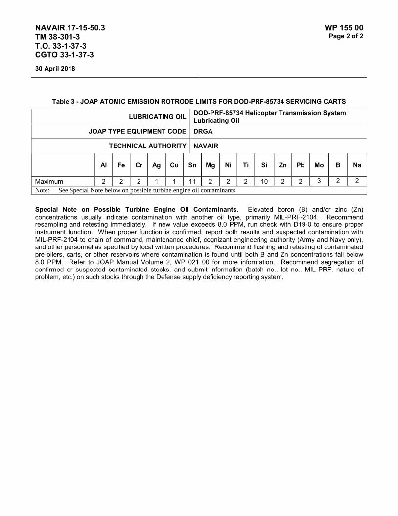
NAVAIR 17-15-50.3 TM 38-301-3 T.O. 33-1-37-3 CGTO 33-1-37-3
WP 155 00 Page 2 of 2
30 April 2018
Table 3 - JOAP ATOMIC EMISSION ROTRODE LIMITS FOR DOD-PRF-85734 SERVICING CARTS
LUBRICATING OIL DOD-PRF-85734 Helicopter Transmission System Lubricating Oil
JOAP TYPE EQUIPMENT CODE DRGA
TECHNICAL AUTHORITY NAVAIR
Al Fe Cr Ag Cu Sn Mg Ni Ti Si Zn Pb Mo B Na
Maximum 2 2 2 1 1 11 2 2 2 10 2 2 3 2 2
Note: See Special Note below on possible turbine engine oil contaminants
Special Note on Possible Turbine Engine Oil Contaminants. Elevated boron (B) and/or zinc (Zn) concentrations usually indicate contamination with another oil type, primarily MIL-PRF-2104. Recommend resampling and retesting immediately. If new value exceeds 8.0 PPM, run check with D19-0 to ensure proper instrument function. When proper function is confirmed, report both results and suspected contamination with MIL-PRF-2104 to chain of command, maintenance chief, cognizant engineering authority (Army and Navy only), and other personnel as specified by local written procedures. Recommend flushing and retesting of contaminated pre-oilers, carts, or other reservoirs where contamination is found until both B and Zn concentrations fall below 8.0 PPM. Refer to JOAP Manual Volume 2, WP 021 00 for more information. Recommend segregation of confirmed or suspected contaminated stocks, and submit information (batch no., lot no., MIL-PRF, nature of problem, etc.) on such stocks through the Defense supply deficiency reporting system.

NAVAIR 17-15-50.3 TM 38-301-3 T.O. 33-1-37-3 CGTO 33-1-37-3
WP 156 00 Page 1 of 2
30 April 2018
TYPE EQUIPMENT Aircraft Engine
MANUFACTURER Rolls Royce
EQUIPMENT/SYSTEM MODEL NUMBER/DESIGNATION
WEAPON SYSTEM PLATFORM(S)
JOAP TYPE EQUIPMENT CODE
RR250-C20W MQ-8B RQAA
LUBRICATING OIL MIL-PRF-23699
TECHNICAL AUTHORITY NAVAIR-4.4.2.3 / MQ-8B Propulsion Engineering Team
STATUS In Use
Table 1 - JOAP ATOMIC EMISSION ROTRODE LIMITS
Fe Ag Al Cr Cu Mg Si B Zn
Abnormal Trend (PPM Increase in 10 Hrs)
4 2 3 2 2 4 12
Normal Range 0-10 0-3 0-8 0-3 0-5 0-10 0-39 Marginal Range 11-12 N/A 9-10 4 6 11-12 40-48 High Range 13-15 4 11-12 5 7 13-14 49-59 Abnormal ≥16 ≥5 ≥13 ≥6 ≥8 ≥15 ≥60 10 10
Fe Accessory drive splines and gears Bearing load surfaces
Fe & Cu Accessory bearing assemblies
Fe Cu & Ag Bearings and gears
Fe & Cu Oil pump assemblies
Fe & Cu Housing bearing liners Accessory housing
NAVAIR 17-15-50.3 TM 38-301-3 T.O. 33-1-37-3 CGTO 33-1-37-3
WP 156 00 Page 2 of 2
30 April 2018
Elevated boron (B) and/or zinc (Zn) concentrations usually indicate contamination with another oil type, primarily MIL-PRF-2104. Recommend resampling and retesting immediately. If new value exceeds 8.0 ppm, run check with D19-0 to ensure proper instrument function. When proper function is confirmed, report both results and suspected contamination with MIL-PRF-2104 to chain of command, maintenance chief, cognizant engineering authority (Army and Navy only), and other personnel as specified by local written procedures. Recommend flushing and retesting of contaminated pre-oilers, carts, or other reservoirs where contamination is found until both B and Zn concentrations fall below 8.0 ppm. Refer to JOAP Manual Volume 2, WP 021 00 for more information. Recommend segregation of confirmed or suspected contaminated stocks, and submit information (batch no., lot no., MIL-PRF, nature of problem, etc.) on such stocks through the Defense supply deficiency reporting system.
NOTES
Some older engines have a Ag cage and failure will show a continuing increase in Fe & Ag instead of Fe Cu & Ag.
High Si will show in the oil samples for the first for second oil changes on a new or overhauled engine.

NAVAIR 17-15-50.3 TM 38-301-3 T.O. 33-1-37-3 CGTO 33-1-37-3
WP 157 00 Page 1 of 2
30 April 2018
TYPE EQUIPMENT INTERMEDIATE GEARBOX CH-53K (NAVY)
MANUFACTURER Sikorsky
EQUIPMENT/SYSTEM MODEL NUMBER/DESIGNATION
WEAPON SYSTEM PLATFORM(S)
JOAP TYPE EQUIPMENT CODE
Int Gbx CH-53K Not Assigned
LUBRICATING OIL DOD-PRF-85734
TECHNICAL AUTHORITY NAVAIR
STATUS In Use
Table 1 – WATER CONTENT VIA AQUATEST * LIMITS
Results
Normal < 1200
Marginal 1200 to 1500
Abnormal > 1500
* For Aquatest Method see Volume 2 Work Packages 009 or 010 depending on instrument being used
All oil samples shall be checked for water content. Water limit shall be 1200 PPM (0.120 percent). Water content that exceeds 1500 PPM shall result in a laboratory recommendation of "J": Change oil; sample after first flight. Water content between 1200 and 1500 PPM shall result in a laboratory recommendation "C": Do not change oil; resample after first flight. If resample results in water content still above 1200 PPM, laboratory recommendation shall be "J": Change oil; sample after first flight.

NAVAIR 17-15-50.3 TM 38-301-3 T.O. 33-1-37-3 CGTO 33-1-37-3
WP 157 00 Page 2 of 2
30 April 2018
This Page Intentionally Left Blank

NAVAIR 17-15-50.3 TM 38-301-3 T.O. 33-1-37-3 CGTO 33-1-37-3
WP 158 00 Page 1 of 2
30 April 2018
TYPE EQUIPMENT TAIL ROTOR GEARBOX CH-53K (NAVY)
MANUFACTURER Sikorsky
EQUIPMENT/SYSTEM MODEL NUMBER/DESIGNATION
WEAPON SYSTEM PLATFORM(S)
JOAP TYPE EQUIPMENT CODE
Tail Rotor Gbx CH-53K Not Assigned
LUBRICATING OIL DOD-PRF-85734
TECHNICAL AUTHORITY NAVAIR
STATUS In Use
Table 1 – WATER CONTENT VIA AQUATEST * LIMITS
Results
Normal < 1200
Marginal 1200 to 1500
Abnormal > 1500
* For Aquatest Method see Volume 2 Work Packages 009 or 010 depending on instrument being used
All oil samples shall be checked for water content. Water limit shall be 1200 PPM (0.120 percent). Water content that exceeds 1500 PPM shall result in a laboratory recommendation of "J": Change oil; sample after first flight. Water content between 1200 and 1500 PPM shall result in a laboratory recommendation "C": Do not change oil; resample after first flight. If resample results in water content still above 1200 PPM, laboratory recommendation shall be "J": Change oil; sample after first flight.

NAVAIR 17-15-50.3 TM 38-301-3 T.O. 33-1-37-3 CGTO 33-1-37-3
WP 158 00 Page 2 of 2
30 April 2018
This Page Intentionally Left Blank

NAVAIR 17-15-50.3 TM 38-301-3 T.O. 33-1-37-3 CGTO 33-1-37-3
WP 159 00 Page 1 of 2
30 April 2018
TYPE EQUIPMENT MAIN GEARBOX CH-53K (NAVY)
MANUFACTURER Sikorsky
EQUIPMENT/SYSTEM MODEL NUMBER/DESIGNATION
WEAPON SYSTEM PLATFORM(S)
JOAP TYPE EQUIPMENT CODE
Main Gbx CH-53K Not Assigned
LUBRICATING OIL DOD-PRF-85734
TECHNICAL AUTHORITY NAVAIR
STATUS In Use
Table 1 – WATER CONTENT VIA AQUATEST * LIMITS
Results
Normal < 1200
Marginal 1200 to 1500
Abnormal > 1500
* For Aquatest Method see Volume 2 Work Packages 009 or 010 depending on instrument being used
All oil samples shall be checked for water content. Water limit shall be 1200 PPM (0.120 percent). Water content that exceeds 1500 PPM shall result in a laboratory recommendation of "J": Change oil; sample after first flight. Water content between 1200 and 1500 PPM shall result in a laboratory recommendation "C": Do not change oil; resample after first flight. If resample results in water content still above 1200 PPM, laboratory recommendation shall be "J": Change oil; sample after first flight.

NAVAIR 17-15-50.3 TM 38-301-3 T.O. 33-1-37-3 CGTO 33-1-37-3
WP 159 00 Page 2 of 2
30 April 2018
This Page Intentionally Left Blank
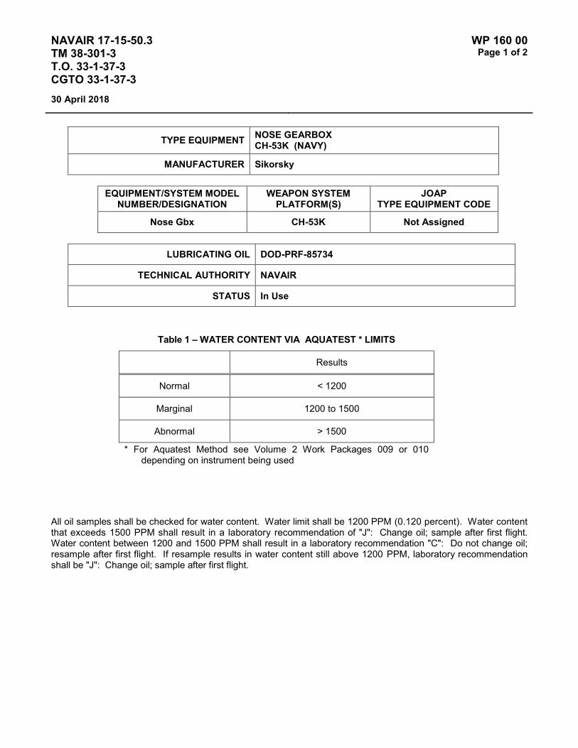
NAVAIR 17-15-50.3 TM 38-301-3 T.O. 33-1-37-3 CGTO 33-1-37-3
WP 160 00 Page 1 of 2
30 April 2018
TYPE EQUIPMENT NOSE GEARBOX CH-53K (NAVY)
MANUFACTURER Sikorsky
EQUIPMENT/SYSTEM MODEL NUMBER/DESIGNATION
WEAPON SYSTEM PLATFORM(S)
JOAP TYPE EQUIPMENT CODE
Nose Gbx CH-53K Not Assigned
LUBRICATING OIL DOD-PRF-85734
TECHNICAL AUTHORITY NAVAIR
STATUS In Use
Table 1 – WATER CONTENT VIA AQUATEST * LIMITS
Results
Normal < 1200
Marginal 1200 to 1500
Abnormal > 1500
* For Aquatest Method see Volume 2 Work Packages 009 or 010 depending on instrument being used
All oil samples shall be checked for water content. Water limit shall be 1200 PPM (0.120 percent). Water content that exceeds 1500 PPM shall result in a laboratory recommendation of "J": Change oil; sample after first flight. Water content between 1200 and 1500 PPM shall result in a laboratory recommendation "C": Do not change oil; resample after first flight. If resample results in water content still above 1200 PPM, laboratory recommendation shall be "J": Change oil; sample after first flight.

NAVAIR 17-15-50.3 TM 38-301-3 T.O. 33-1-37-3 CGTO 33-1-37-3
WP 160 00 Page 2 of 2
30 April 2018
This Page Intentionally Left Blank