jkr lecture design and construction of roads on...
TRANSCRIPT
JKR LECTURE
Design and construction of
roads on soft clay
Dr C T Toh, Ir Chee Sai Kim
DR C T TOH CONSULATANT
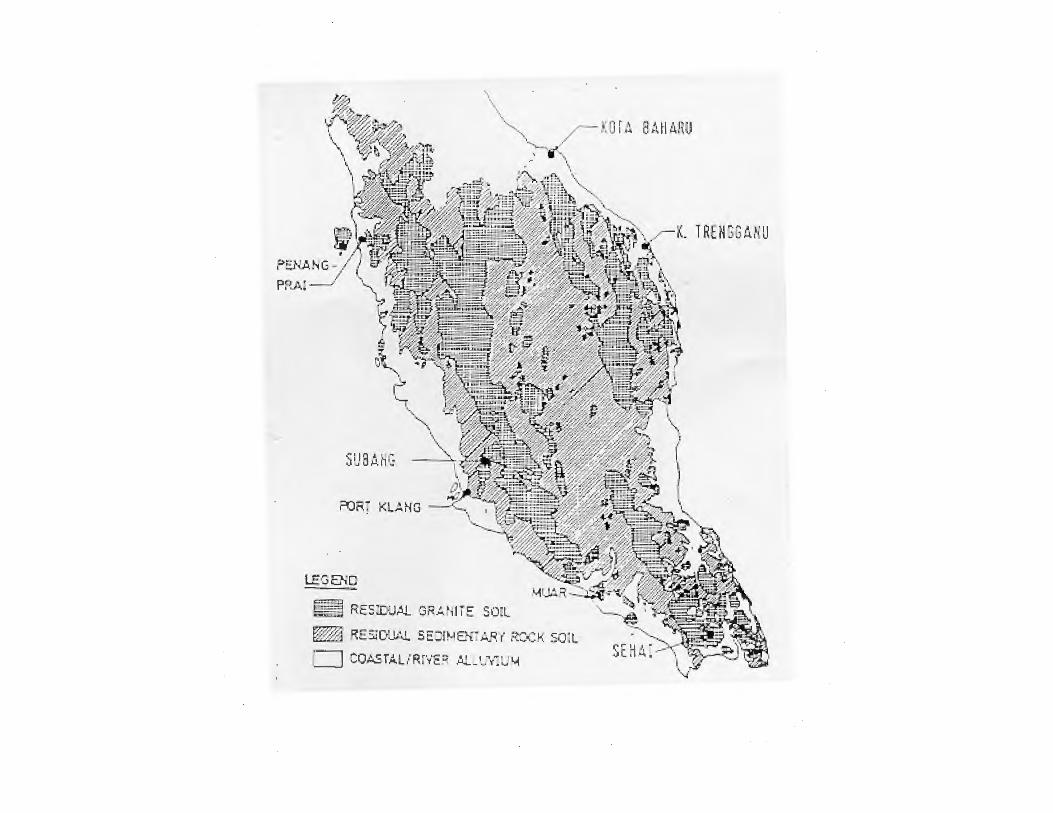
DISTRIBUTION OF SOFT CLAY
• LOW LYING AREAS ON THE WEST
COAST AND EAST COAST OF
PENINSULAR MALAYSIA.
• COASTAL AND ALLUVIAL PLAINS OF
SABAH AND SARAWAK.
SU8Ah~
.~ RES:O:.JAL OR'Atlli !:: SO"L
~ RE5JC(IA1. SE~H-tEN ~M'r' RXK SOiL
c::J CO~TAURf'v'E~ AL-'~~r":L' l-1
8AH 4JW
~~K- T RtNSGMiU

.~
~ ~
Ple i .s:!ocenf! ond Re".;:en t sedim.en ts ; rna in 1,. · r loodplai~5 and del lOS wi!h lcw_lying, f.hll land"$. ·
Pu: ~ P"l.f!iS.t(l.::en.e :sedlrn..el'lt(l-r}' rock$: lr»d\lir:.lling !o mou.n to in 4;1\.1"5- te-1 H:t in .
.... ··
T~
LSK wd
major urba.n centres: [fl So r a ... mk

SOFT CLAY TOPICS
(i) Stability
(ii) Settlement
(iii) Actual behavior of embankments
(iv) Embankment stabilization and settlement mitigation

SOFT CLAY STABILITY TOPICS
• Mechanism of instability and the development of the mechanism
• Methods of stability analysis
• Relevant parameters and factors affecting stability
• Soil investigation to obtain relevant parameters
• Design factors of safety
• Lateral movements
SOFT CLAY SETTLEMENT
TOPICS
• Consolidation
• Relevant soil investigation
• Methods of analysis
SOFT CLAY. EMBANKMENT
BEHAVIOR
• Pore pressure behavior
• Pre-consoIidation pressure
• Lateral movements
• Undrained and drained volume change
• Settlement due to lateral movements
• Gain in strength

SOFT CLAY TREATMENT
TOPICSPurpose of treatment :
• Mitigate long term settlement
• Enhance the stability of the embankment
• Reduce lateral movements
METHODS
• Stability berms
• Stage construction with gain in strength
• Preload / surcharge
• Vertical drains
• Stone columns
• Pile embankments
SOFT CLAY STABILITY
MECHANISMS
• Slope failure mostly circular extending into
the soft clay.
• However if thin soft clay present failure
can be planar.

Soft clay. stability
Soft clay stability
METHODS OF STABILITY ANALYSIS
Soft clay stability. Critical
conditions
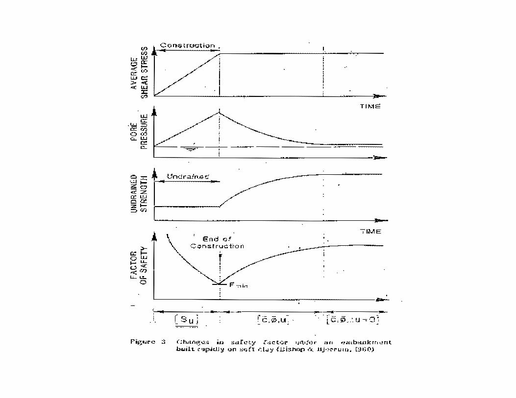
• Embankment instability mostly occur within a short period (days or a few weeks) after completion of embankment construction when pore pressures highest
• Short term conditions critical
• Use total stress analysis. No need to know pore pressure distribution. Use un-drained shear strength.
• Can also use effective stress analysis but this will require knowledge of pore pressures
TIM::::
-;-IME
L-------------------------------~~~--~---------------~
--~~~~~----------------------------·-------r ·- - -. C,0,U~
( ~ hlLn~1.2:.:;; in :=;af 1.:! ty i>J.C tOt'" •JI:l.•.:'O r i":l t1 •..!'J(Lb~.LJ:Ik rr• 1...! r1 t .I.M..IH t "'.l!p.ic.JJ '1 on };-~:; f1 r. L-:.1 't { ll is.nnp a. J:l.j-~C""r u Ill. [~I) f:l)

PARAMETERS
TOTAL STRESS ANALYSIS:
• Un-drained shear strength of the soft clay. Best to use the vane shear strength.Cu or Suv
• No need to consider pore pressures. Total implies all effects encompassed in the un-drained shear strength.
• Shear strength of the embankment fill material. Usually c and phi

PARAMETERS
EFFECTIVE STRESS ANALYSIS
• C’ AND PHI’ OF SOFT CLAY
• C’ AND PHI’ OF EMBANKMENT
• PORE PRESSURES THROUGHOUT
SOFT CLAY AT FULL EMBANKMENT
HEIGHT – This is difficult and will need a
coupled effective stress finite element with
consolidation to estimate.
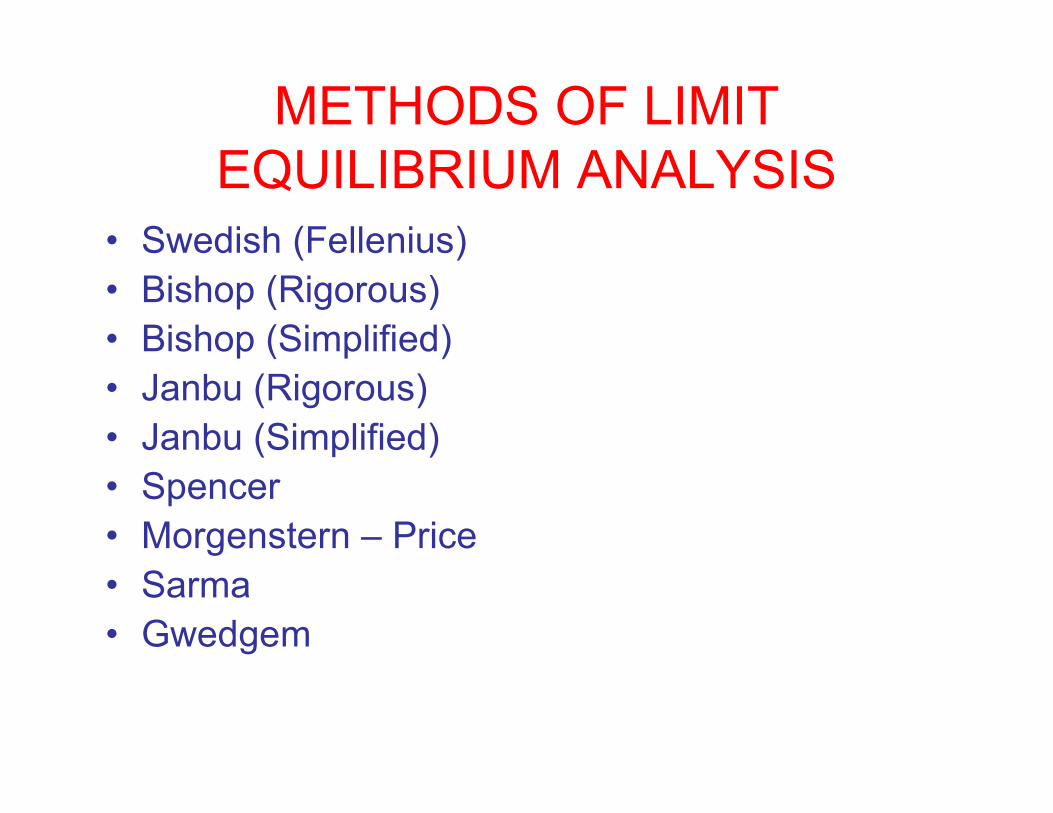
METHODS OF LIMIT
EQUILIBRIUM ANALYSIS
• Swedish (Fellenius)
• Bishop (Rigorous)
• Bishop (Simplified)
• Janbu (Rigorous)
• Janbu (Simplified)
• Spencer
• Morgenstern – Price
• Sarma
• Gwedgem
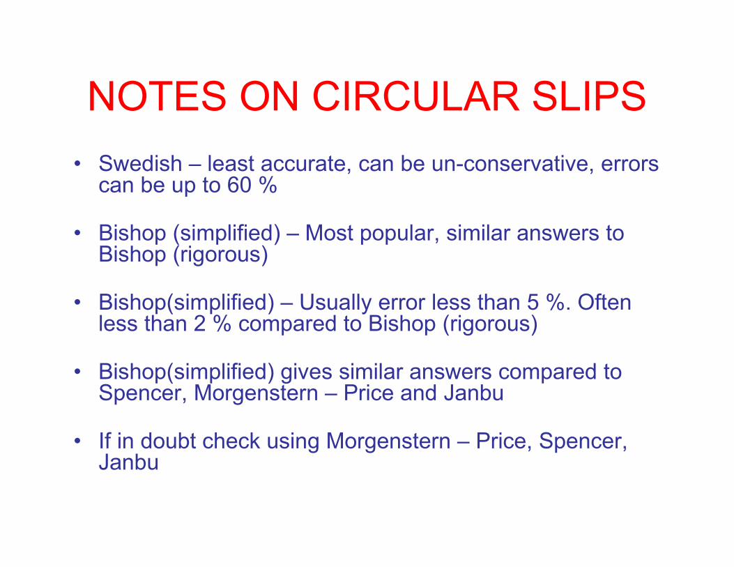
NOTES ON CIRCULAR SLIPS
• Swedish – least accurate, can be un-conservative, errors can be up to 60 %
• Bishop (simplified) – Most popular, similar answers to Bishop (rigorous)
• Bishop(simplified) – Usually error less than 5 %. Often less than 2 % compared to Bishop (rigorous)
• Bishop(simplified) gives similar answers compared to Spencer, Morgenstern – Price and Janbu
• If in doubt check using Morgenstern – Price, Spencer, Janbu
Comparisons on circular slips by
Whitman & Bailey (1967)
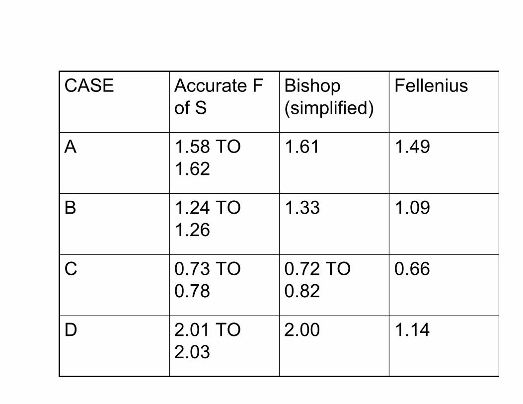
1.142.002.01 TO
2.03
D
0.660.72 TO
0.82
0.73 TO
0.78
C
1.091.331.24 TO
1.26
B
1.491.611.58 TO
1.62
A
FelleniusBishop
(simplified)
Accurate F
of S
CASE

COMPARISONS OF METHODS
OF STABILITY ANALYSIS BY
FREDLUND AND KRAHN

1.341.831.191.741.452.04Janbu
1.251.831.121.771.382.08Morgenster
n - Price
1.251.831.121.761.372.07Spencer
1.251.831.121.771.382.08Bishop
(simplified)
654321Method /
case
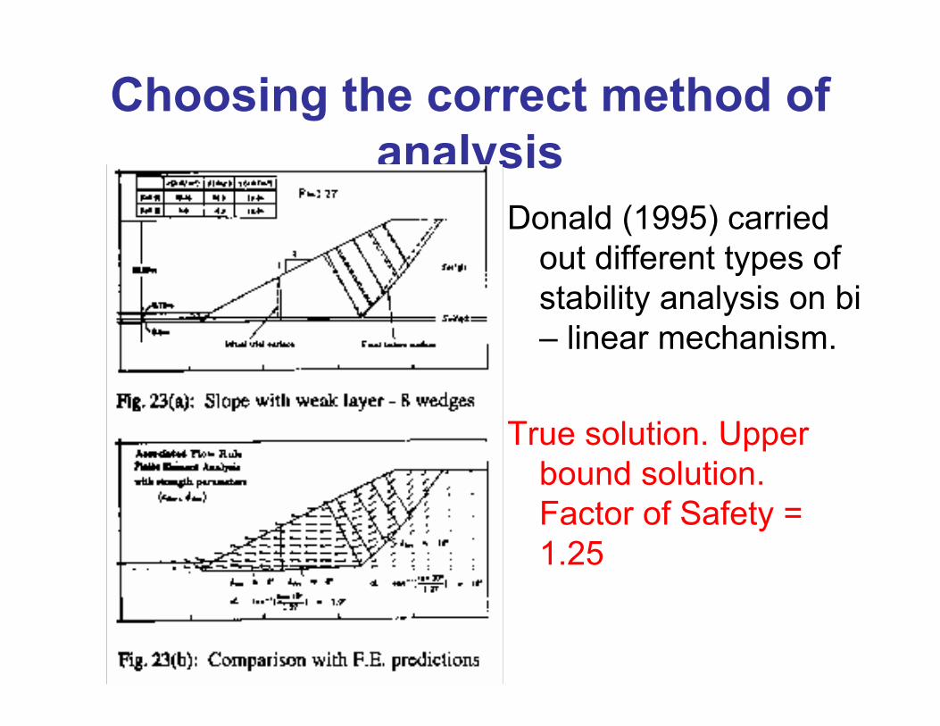
Choosing the correct method of
analysis
Donald (1995) carried
out different types of
stability analysis on bi
– linear mechanism.
True solution. Upper
bound solution.
Factor of Safety =
1.25
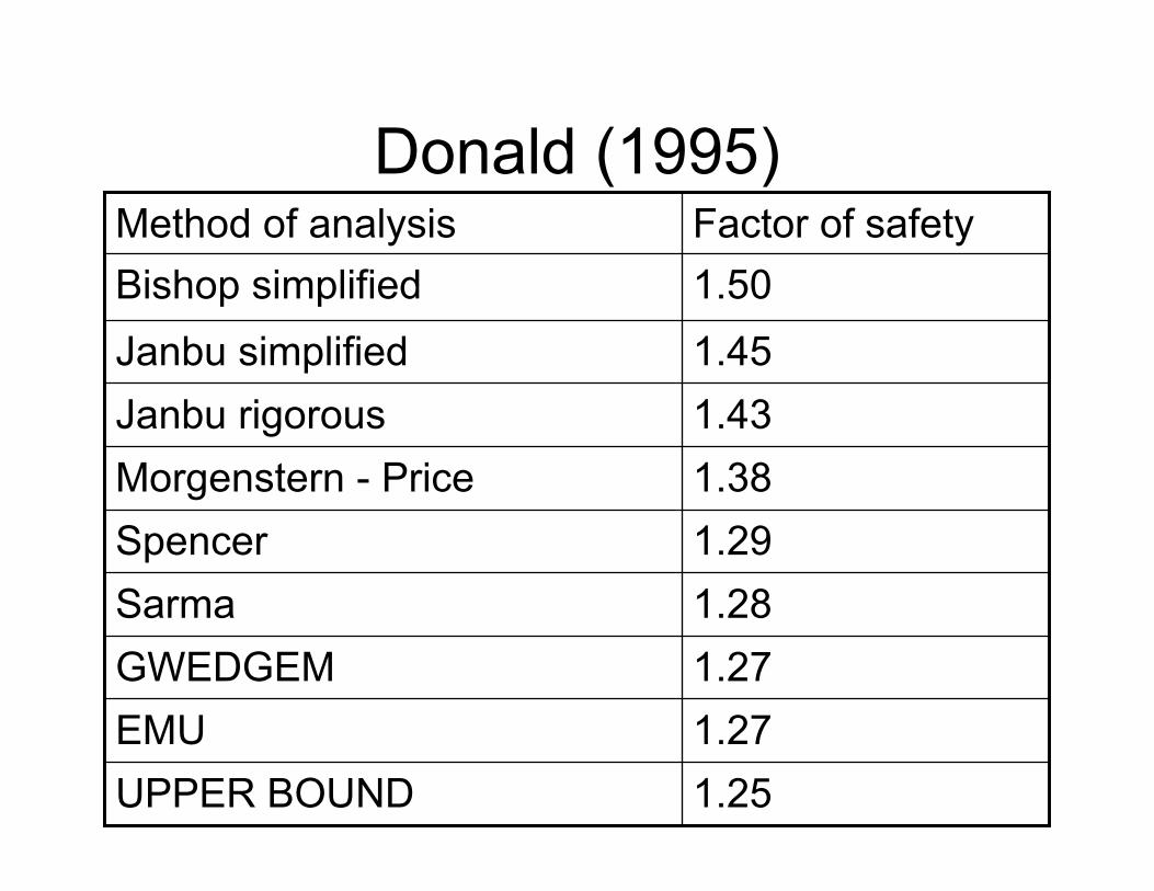
Donald (1995)
1.25UPPER BOUND
1.27EMU
1.27GWEDGEM
1.28Sarma
1.29Spencer
1.38Morgenstern - Price
1.43Janbu rigorous
1.45Janbu simplified
1.50Bishop simplified
Factor of safetyMethod of analysis

Soft clay total stress parameters
VANE
• Most common method of strength indexing
• Approximate empirical tool for strength
measurement, need to relate the vane
shear strength to the actual shear strength
by back analysis of failed embankments
• Bjerrum, Larsson and Ladd correction
factors
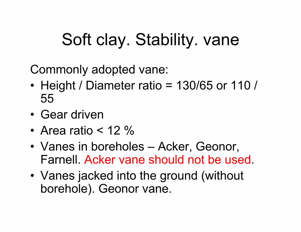
Soft clay. Stability. vane
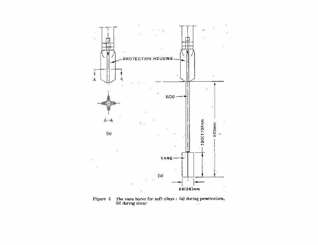
Commonly adopted vane:
• Height / Diameter ratio = 130/65 or 110 / 55
• Gear driven
• Area ratio < 12 %
• Vanes in boreholes – Acker, Geonor, Farnell. Acker vane should not be used.
• Vanes jacked into the ground (without borehole). Geonor vane.
. 1
+ I
A-A
(a}
PROTECTION HOUSING
VA N E -----t-"
(b)
I I ~
l 65{55)mm
!
E. E· E ,-. E 0 0 -- 0 , ....... lr.l
0 Q? .....
J
Figur~ 5 The vane borer- ror soft clays; (a) during penetrntiont (b) during shear

Soft clay. Stability. vane
Test procedure
• Penetrate vane beneath borehole depth – 3 diameter (BS) or 5 diameter (Chandler) or 500 mm (Norwegian)
• Rate of rotation – 6 to 12 degree / min
• Time to failure – 5 min (BS) ; 1 to 3 min (Norwegian)
• If carried out inside borehole, can be disturbed and lower shear strengths. Preferable independent of borehole
Soft clay. Stability. vane
• In 1973, Bjerrum showed that embankments on
soft clay failed when using vanes to design even
if F of S > 1.0 theoretically.
• Bjerrum attributed this to:
(i) vane shear tests carried out at high strain rate
overestimates field undisturbed strength
(ii) Vane unable to measure the effects of
anisotropy – different strengths in horizontal and
vertical directions
Soft clay, stability. Vane
Wroth (1974) quoting the work of Donald et
al (1977) and Menzies & Merrifield(1980)
concluded:
Shear stress distribution around the vane is
different from that assumed when
computing the vane shear strength from
the measured torque.
Soft clay. Stability. vane
Donald et al 91973) and Tavenas & Leroueil
(1980) concluded:
(i) On the complexity in analyzing the vane
(ii) At best an approximate tool for indexing
strength
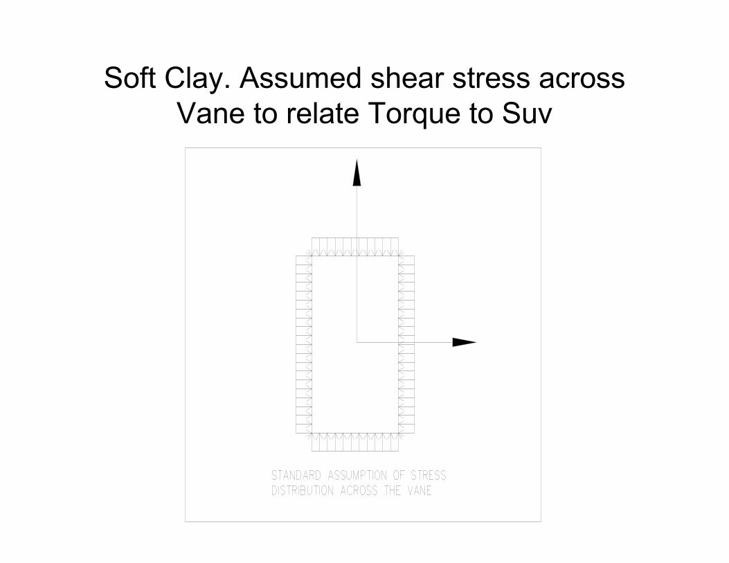
Soft Clay. Assumed shear stress across
Vane to relate Torque to Suv
ANALYSIS OF VANE TO GET
SUV
• Measure torque
• Torque = (Suv x top area of vane x
moment arm) + (Suv x side perimeter area
of vane x moment arm).
• Assume Suv same throughout
• Torque gives Suv
ANALYSIS OF VANE TO GET
SUV
Torque =
Suv x 3.14 x d2 / 4 x d /4 +
Suv x 3.14 x d x l x d/2
Measure torque and calculate Suv
Basic problem is asumption that Suvconstant across the top and side of vane
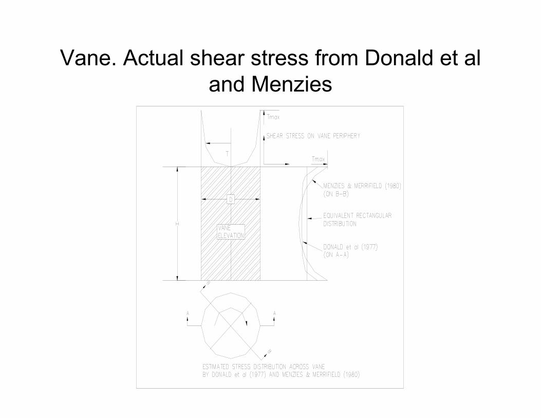
Vane. Actual shear stress from Donald et al
and Menzies

Error in basic assumption
• Analysis of Suv distribution across
diameter and height of vane implies that
basic assumption to relate Torque to Suv
is not correct
• Therefore there is need to correct vane
shear strengths
Soft clay. Stability. vane
Methods of indexing vane:
• Bjerrum correction factor dependent on
plasticity index
• Larsson correction factor dependent on
liquid limits
Undrained shear strength = correction factor
x Vane shear strength
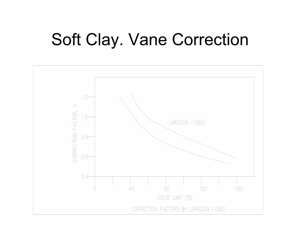
Soft Clay. Vane Correction
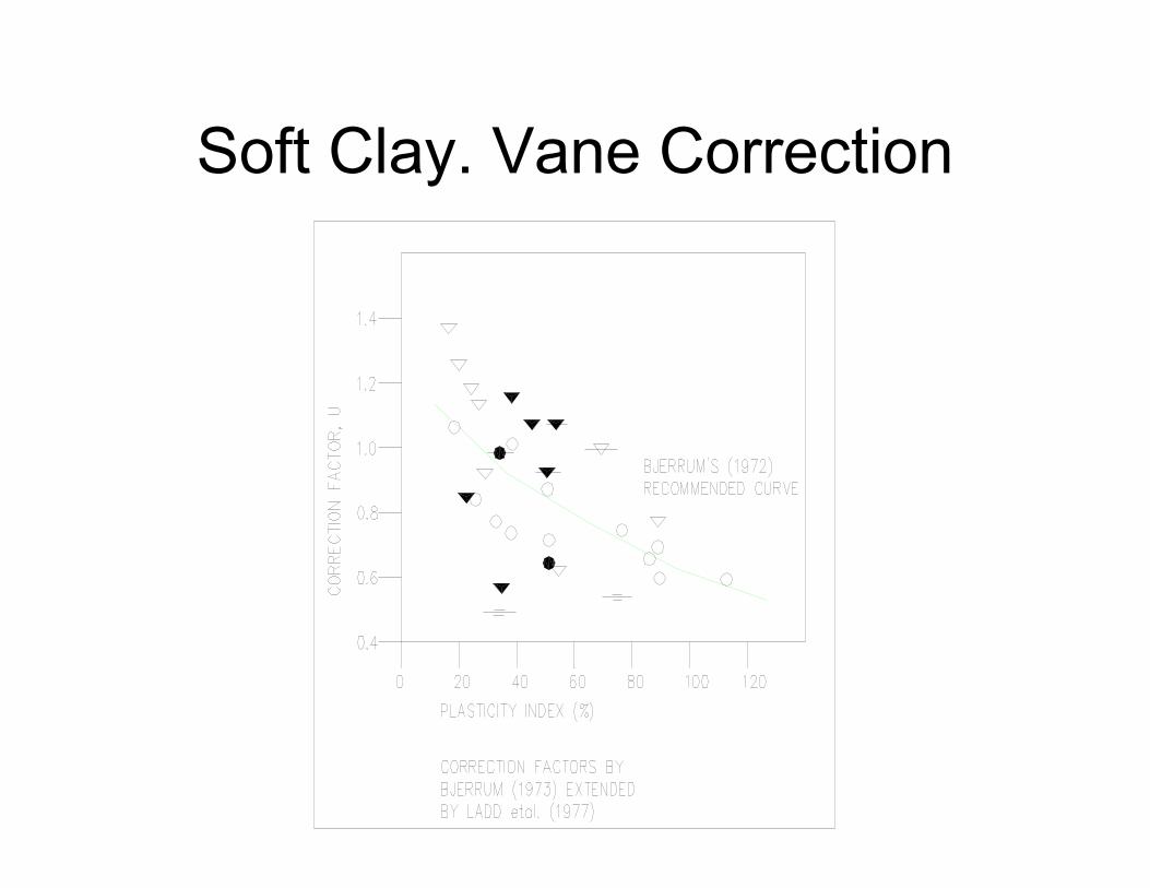
Soft Clay. Vane Correction
Soft clay. Stability. Local correction
factors
Chee Sai Kim has analyzed a number of
embankment failures in soft clay and
compared against the properties of the
soft clay.
The correction factors are plotted against
the set of international data. The trends
are similar.
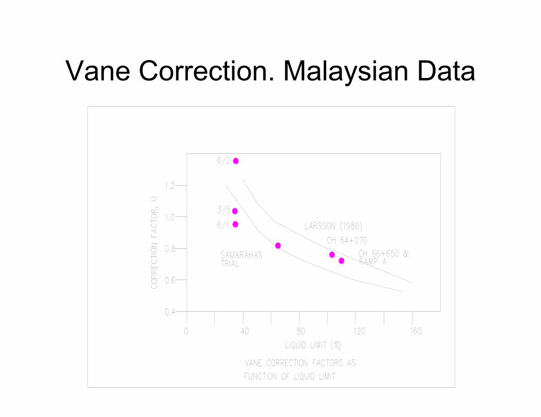
Vane Correction. Malaysian Data
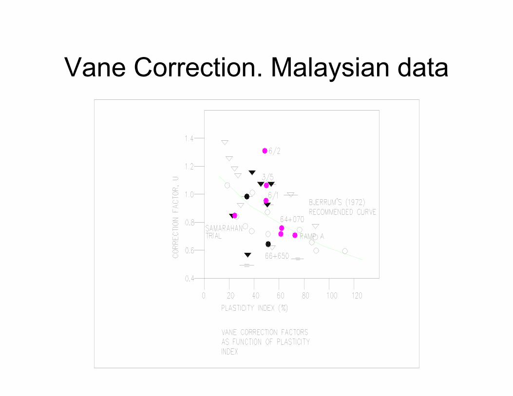
Vane Correction. Malaysian data
Soft clay. Stability. Factors of
safety
JKR. Immediate at end of construction without considering effects of gain in strength = 1.2
Should try to obtain 1.4 to 1.5 if gain in strength not considered.
If stage construction with gain in strength required, at each stage the F. of S. with gain in strength at each stage should be 1.2
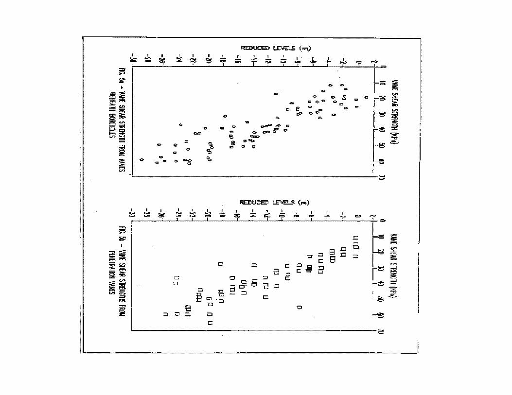
Soft Clay. Stability. vane
Scatter in vane shear strength expected at
any location:
• Natural variability of the soil e.g. sand
lenses, organic matter, etc
• Deviation from standard method of testing
• Variations in degree of disturbance due to
rotation of the vane during insertion
I &::
I ....,. - I I -......, - -
0
I i\lii':
..!.. I I
- ..,:. =
0
I. 1:;111
I
~ I - --
~--------------------------------------~--------------------~-----------~
I g
-. ...
I .....:. -- I -.....
B
I I 1 ~ ~ 0:
..!.. ,
...... ~ I
I;' I
c::
e:
0
I -0'1
I ...... I ..,..
a c Be
~--------------------------------~----------------------------------------~
Soft clay. Stability. vane
Scatter would imply that any site there must be
sufficient number of vane tests to ensure that the
complete range of the scatter is actually
captured.
Designer must then decide whether to use lower
bound, median or some other values.
Computation of median values should not include
exceptionally high values which may be due to
tests in sand layer, shells, roots, etc
Soft clay. Stability. Choice of
strength
Generally vane correction factors should be
applied to median values
Lesser or no correction factors if lower bound vane
shear strengths are adopted.
Usually applying correction factor to median would
result in near lower bound conditions.
Also designer need to make judgment about
degree of disturbance if vane tests in boreholes
Soft clay. Stability. Strength
• Vane shear strengths from vanes in
boreholes generally lower compared to
jack – in vanes because of borehole
disturbance.
• There is a natural scatter in the vane
shear strength results due to natural
heterogeinity.

Soft clay. settlement
Basic parameters for analysis:
• Depth and thickness of the different layers;
• Drainage boundaries – sand layers
• Over consolidation ratio OCR
• Cc / ( 1 +eo) – compressibility index after pc
• Cr / (1 + eo) – compressibilty index before pc
• Cv - coefficient consolidation after pc
• Cvr - coefficient consolidation before pc
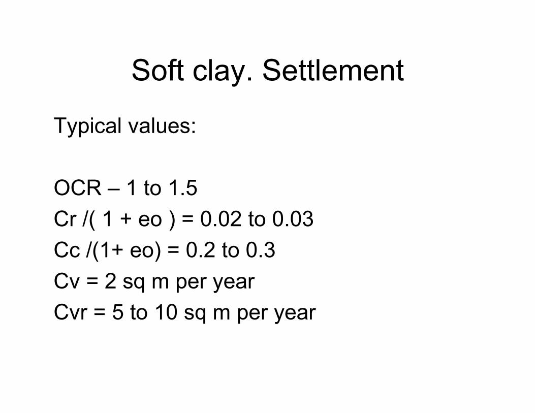
Soft clay. Settlement
Typical values:
OCR – 1 to 1.5
Cr /( 1 + eo ) = 0.02 to 0.03
Cc /(1+ eo) = 0.2 to 0.3
Cv = 2 sq m per year
Cvr = 5 to 10 sq m per year

Soft clay. Settlement
Soil investigation method
• Boreholes
• Undisturbed samples – use stationary thin wall piston sampler for minimal disturbance
• Laboratory oedometer tests. Should modify BS standard for load increments. Use small (10 kPa) pressure increments until pass pc.
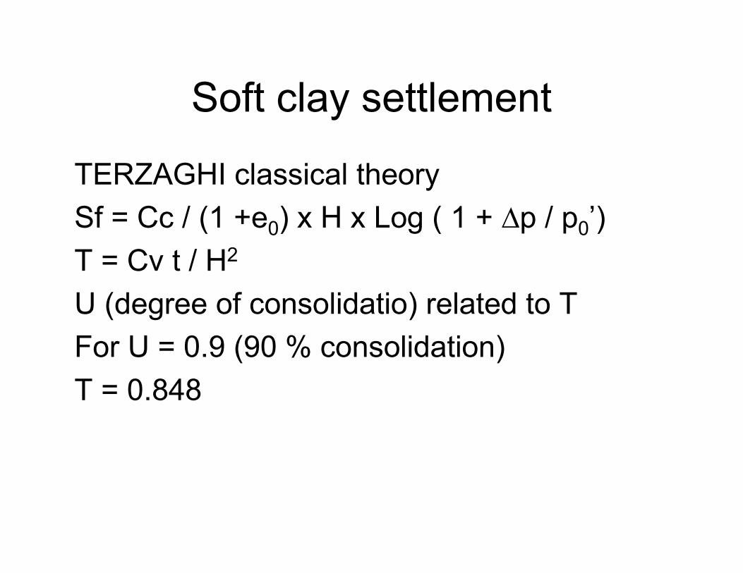
Soft clay settlement
TERZAGHI classical theory
Sf = Cc / (1 +e0) x H x Log ( 1 + ∆p / p0’)
T = Cv t / H2
U (degree of consolidatio) related to T
For U = 0.9 (90 % consolidation)
T = 0.848

Soft clay settlement
Problem is Terzaghi theory is for a point in the soil layer.
In calculating U and time, often simplify by using H as the drainage distance.
This is not correct and leads to incorrect answers
Proper analysis of Terzaghi equation requires finite difference or finite element numerical methods
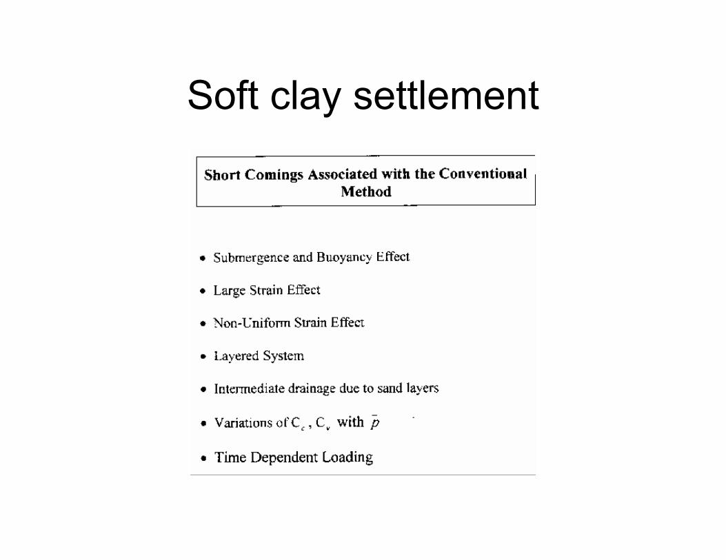
Soft clay settlement
Soft clay settlement
Conventional hand calculations using charts
not accurate
Not possible to calculate time effects for
layered soils using hand calculations and
charts
Require finite difference (1 dimensional) or
finite element (2 dimensional) methods

Soft clay settlement
Design criteria:
Peninsular MHA JKR – Post construction
settlement less than 10 % of total consolidation
settlement
Sarawak JKR – Post construction settlement of
200 mm over first 3 post construction years or
over first 5 post construction years
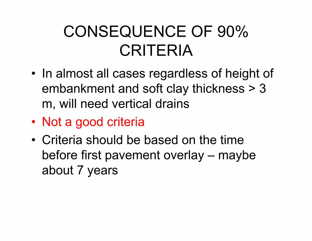
CONSEQUENCE OF 90%
CRITERIA
• In almost all cases regardless of height of
embankment and soft clay thickness > 3
m, will need vertical drains
• Not a good criteria
• Criteria should be based on the time
before first pavement overlay – maybe
about 7 years

Soft Clay. Embankment behavior
pore pressures
2 TO 3 DISTINCT PHASES
3RD PHASE NEAR
INSTABILITY

Soft clay. Embankment behavior
pore pressures

Soft clay. Embankment behavior

Soft clay. Embankment behavior

Embankment behavior
Settlement that is measured is due to two
components:
• Consolidation settlement
• Lateral movements causing embankment
to settle

Soft clay. Embankment behavior
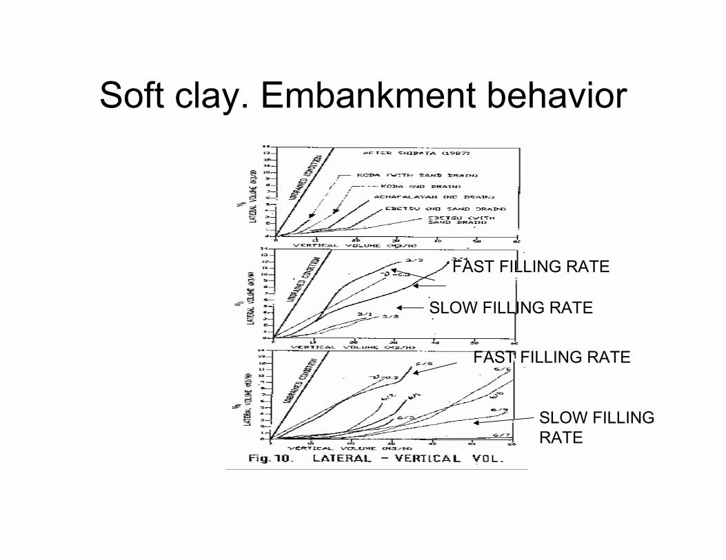
Soft clay. Embankment behavior
FAST FILLING RATE
SLOW FILLING RATE
FAST FILLING RATE
SLOW FILLING
RATE
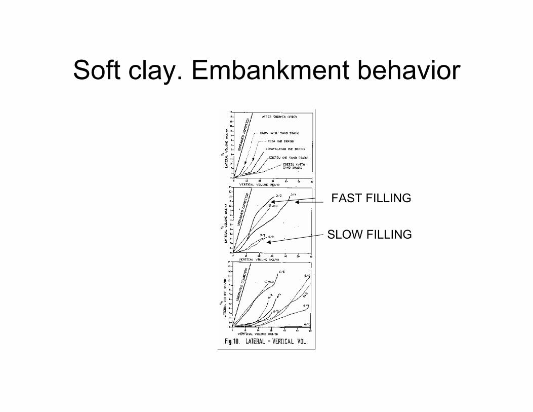
Soft clay. Embankment behavior
FAST FILLING
SLOW FILLING
EMBANKMENT FILLING RATE
• SLOW FILLING RATE RESULTS IN
LARGER CONSOLIDATION AND LESS
LATERAL MOVEMENT
• FASTER FILLING RESULTS IN HIGHER
PORE PRESSURES, HIGHER LATERAL
MOVEMENTS AND LOW DEGREE OF
CONSOLIDATION
EMBANKMENT FILLING RATE
• FAST RATE OF FILLING CAN LEAD TO
TENSION CRACKS
• PREFER TO KEEP FILLING RATE TO
LESS THAN 500 MM (TWO LAYERS A
WEEK) IF NO STONE COLUMNS

Soft clay. Embankment behavior
SH = LATERAL
COMPONENT
ST = TOTAL
SETTLEMENT
SC = CONSOLIDATION
COMPONENT
SC = ST - SH
SLOW FILLING
HIGH DEGREE
OF CONSOLIDATION
LOW SH HIGH SC
FAST FILLING
LOW DEGREE
CONSOLIDATION
HIGH SH
LOWER SC

INCLINOMETER U LATERAL MOVEMENT
Z
DEPTH
SHEAR STRAIN = ∆U / ∆ Z
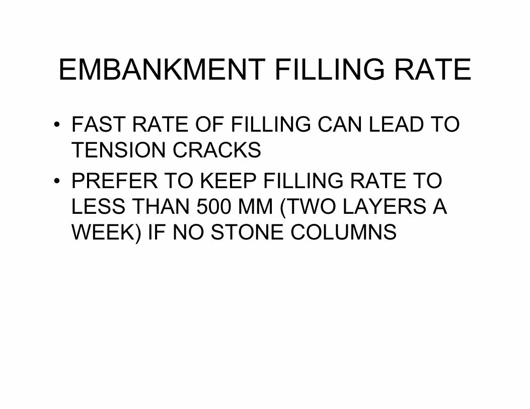
Soft clay. Embankment behavior
up to failure
CENTRE PIEZO
EDGE PIEZO
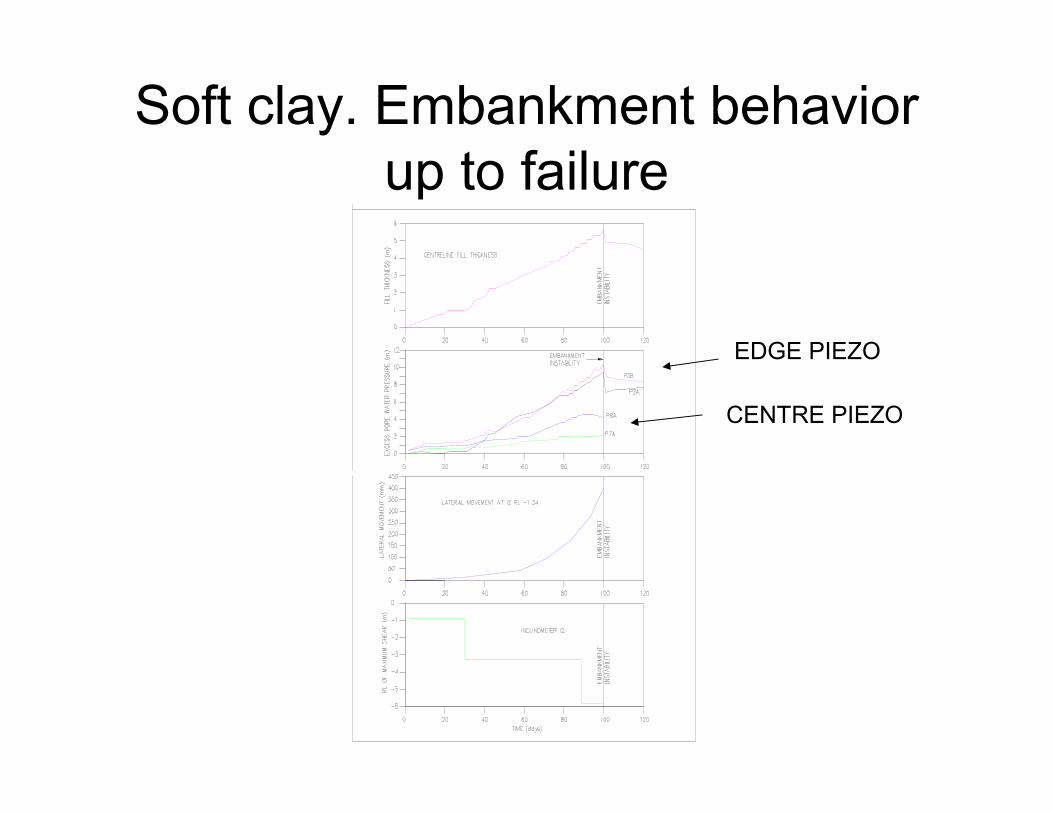
Soft clay. Embankment behavior
up to failure

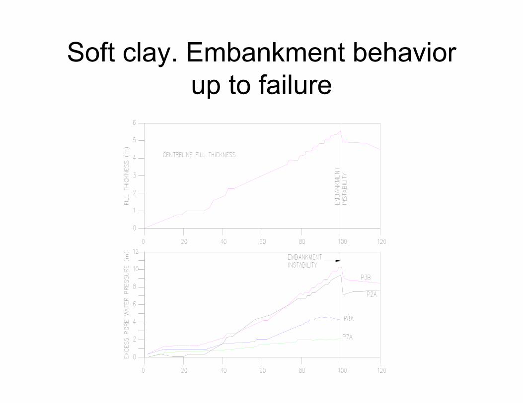
Soft clay. Embankment behavior
up to failure

Soft clay. Stability back analysis
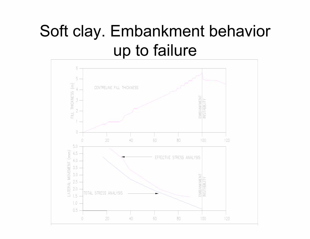
Soft clay. Embankment behavior
up to failure

Soft Clay. Stability. Backanalysis

Soft clay. Stability back analysis
GAIN IN STRENGTH
• Yes if there is consolidation;
• Lesser if there has been larger lateral
movements (Sh high) and lower degree of
consolidation (Sc low)
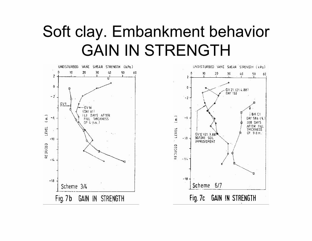
Soft clay. Embankment behavior
GAIN IN STRENGTH

Soft clay. Embankment behavior
GAIN IN STRENGTH
COMMON METHODS OF SOFT
CLAY TREATMENT
• Surcharge without prefabricated vertical
drains
• Surcharge with prefabricated vertical
drains
• Stone columns
• Pile embankments

SURCHARGE WITHOUT PVD
• Just build embankment to a height higher
than the final height and allow the
embankment to settle until an acceptable
post construction settlement.
• Consolidation settlement analysis as
discussed earlier
SURCHARGE WITH PVD
• Use prefabricated vertical drains to
accelerate consolidation settlement and
reduce surcharge time.
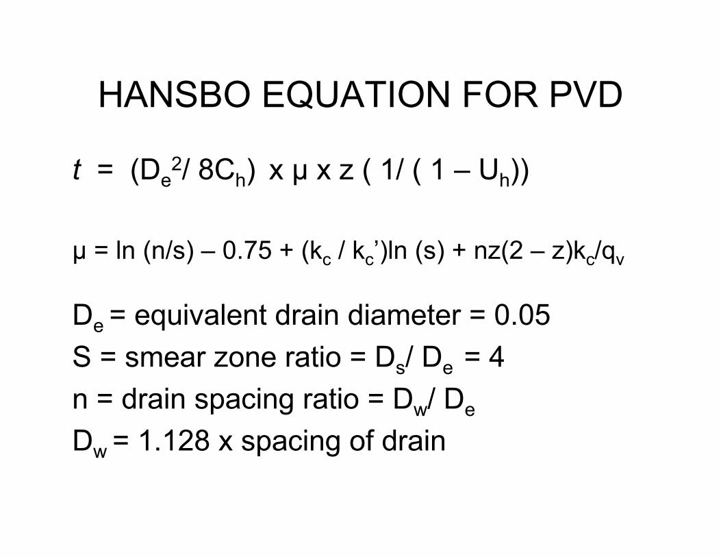
HANSBO EQUATION FOR PVD
t = (De2/ 8Ch) x µ x z ( 1/ ( 1 – Uh))
µ = ln (n/s) – 0.75 + (kc / kc’)ln (s) + nz(2 – z)kc/qv
De = equivalent drain diameter = 0.05
S = smear zone ratio = Ds/ De = 4
n = drain spacing ratio = Dw/ De
Dw = 1.128 x spacing of drain
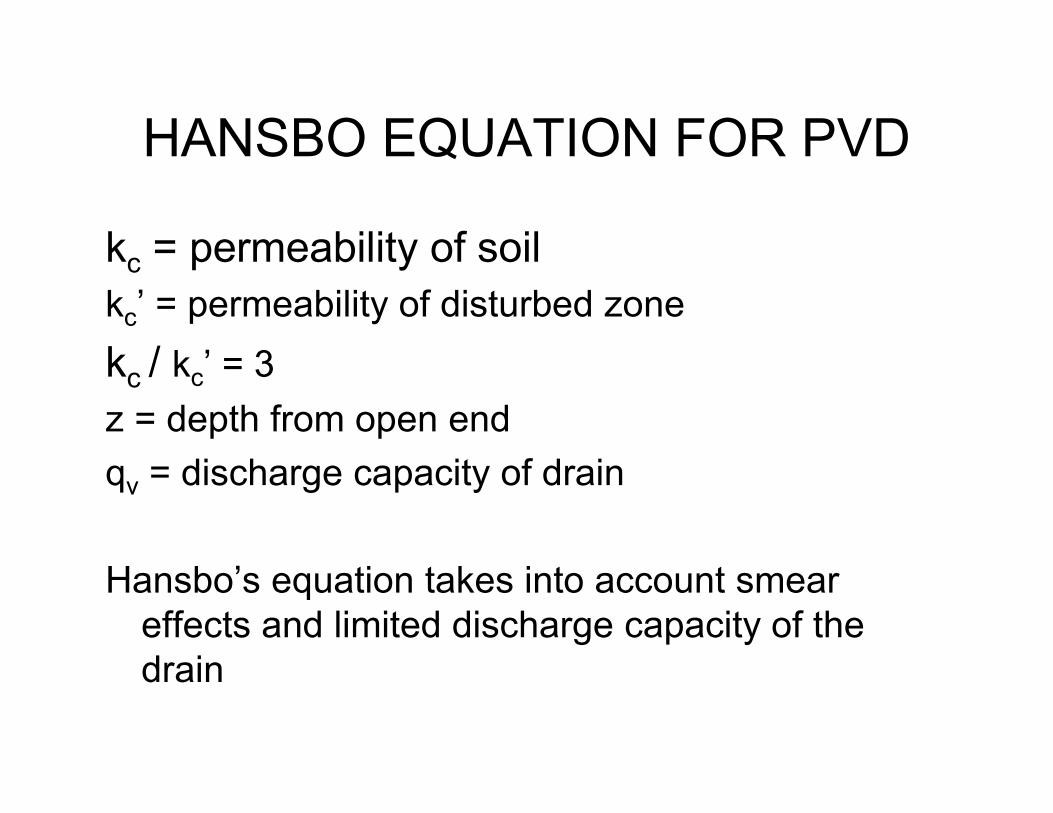
HANSBO EQUATION FOR PVD
kc = permeability of soil
kc’ = permeability of disturbed zone
kc / kc’ = 3
z = depth from open end
qv = discharge capacity of drain
Hansbo’s equation takes into account smear
effects and limited discharge capacity of the
drain
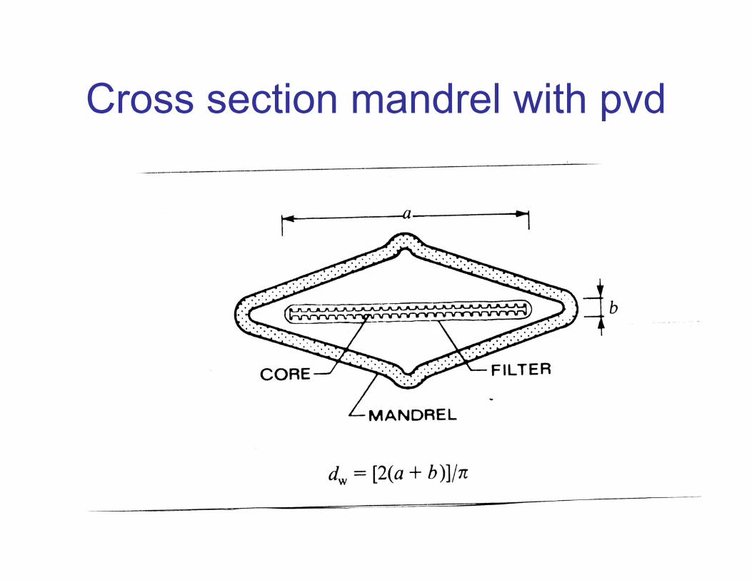
Cross section mandrel with pvd
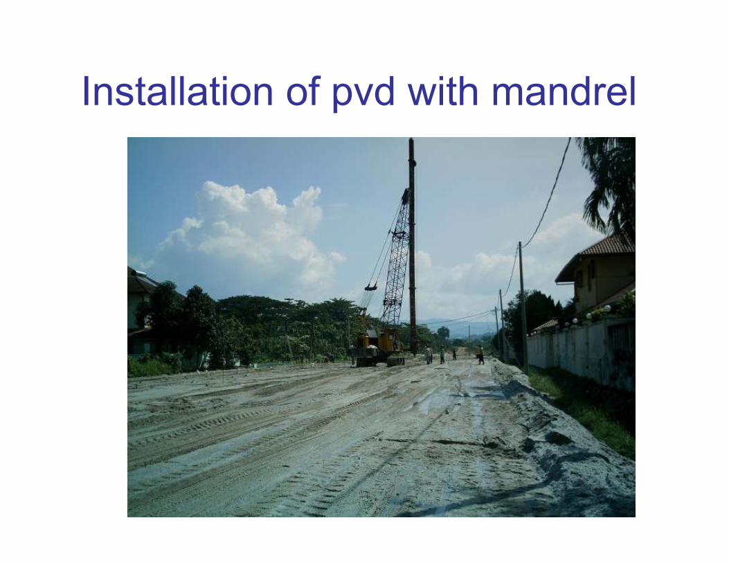
Installation of pvd with mandrel
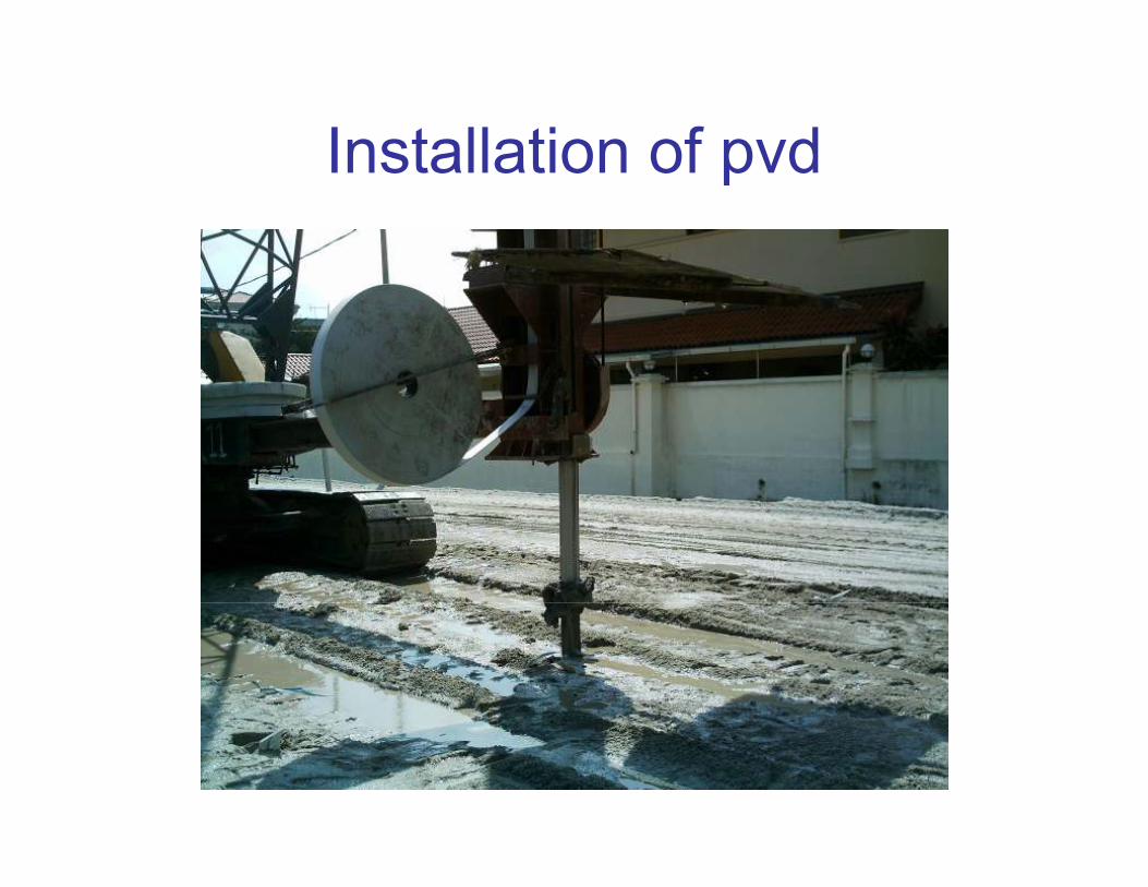
Installation of pvd
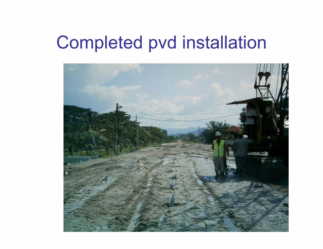
Completed pvd installation
STONE COLUMNS
STONE COLUMNS
• Adopted to stabilize the soft clays and
loose sands to support the highway
embankments and retaining walls.
• To ensure that adequate factor of safety
against stability
• To minimize post construction settlement
si c::i 0::::
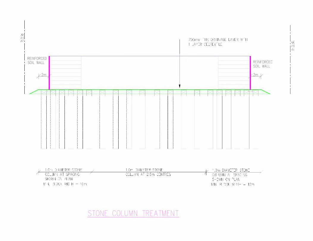
REINFORCED SOIL WALL
v2m 1
f I i I i I [ ,_1 f ~- 1 i I
I )- 1 [ ,_1 f )- 1 i I i I i I i I [ ,_ 1 I I i I i ,_1 I )- 1 LJ
1.0m DIAMETER STONE COLUMN AT SPACING SHOWN ON PLAN
MIN . BLOCK WIDTH = 10m
i:-0 ii':
1.0m DIAMETER STONE COLUMN AT 2.5m CENTRES
STONE COLUMN TREATMENT
-750mm THK DRAINAGE LAYER WITH 1 LA YEP GEOTEXTILE
H
H
H
H
H
1.0m DIAMETER STONE COLUMN AT SPACING SHOWN ON PLAN
REINFORCED SOIL WALL
2m~
MIN. BLOCK WIDTH = 10m
si c::i 0::::

STONE COLUMNS
• Developed by KELLER in 1957
• Method of constructing columns of
compacted stones through weak cohesive
soils by use of deep vibrators
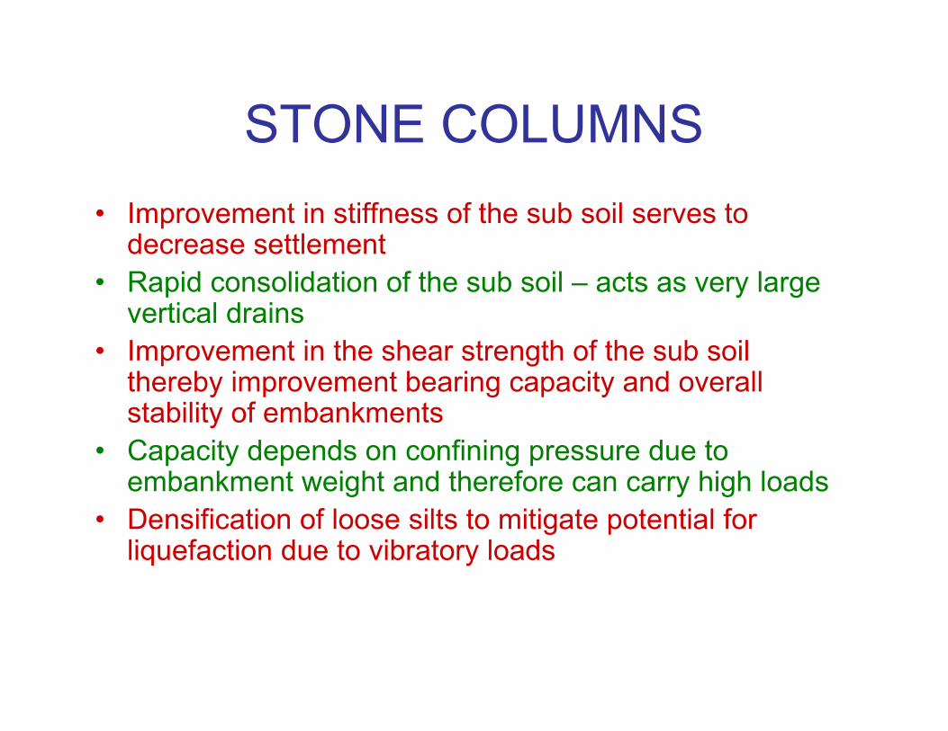
STONE COLUMNS
• Improvement in stiffness of the sub soil serves to decrease settlement
• Rapid consolidation of the sub soil – acts as very large vertical drains
• Improvement in the shear strength of the sub soil thereby improvement bearing capacity and overall stability of embankments
• Capacity depends on confining pressure due to embankment weight and therefore can carry high loads
• Densification of loose silts to mitigate potential for liquefaction due to vibratory loads
STONE COLUMNS
• Usually 800 mm to 1000 mm diameter
• Usual stone column spacing between 1.5
m and 2.5 m centers
• Depth usually between 6 m and 20 m
CONSTRUCTION OF STONE
COLUMNS
• Vibrator to penetrate to design depth
• Penetration by jacking – in (dry method) or by flushing – in with water (wet method),
• Fill the resulting cavity with clean, hard, inert stones.
• Necessary for the stone fill to be introduced and compacted in stages.
• Each charge of stones to be thoroughly compacted.
WET and DRY METHODS
Two methods of forming stone columns:
• WET method where water is used to flush
out soils and stones fed into the hole –
VIBRO REPLACEMENT
• DRY method where mandrel is jacked into
the ground and stones fed through
mandrel – VIBRO- DISPLACEMENT

Stone Column Installation MethodStone Column Installation Method
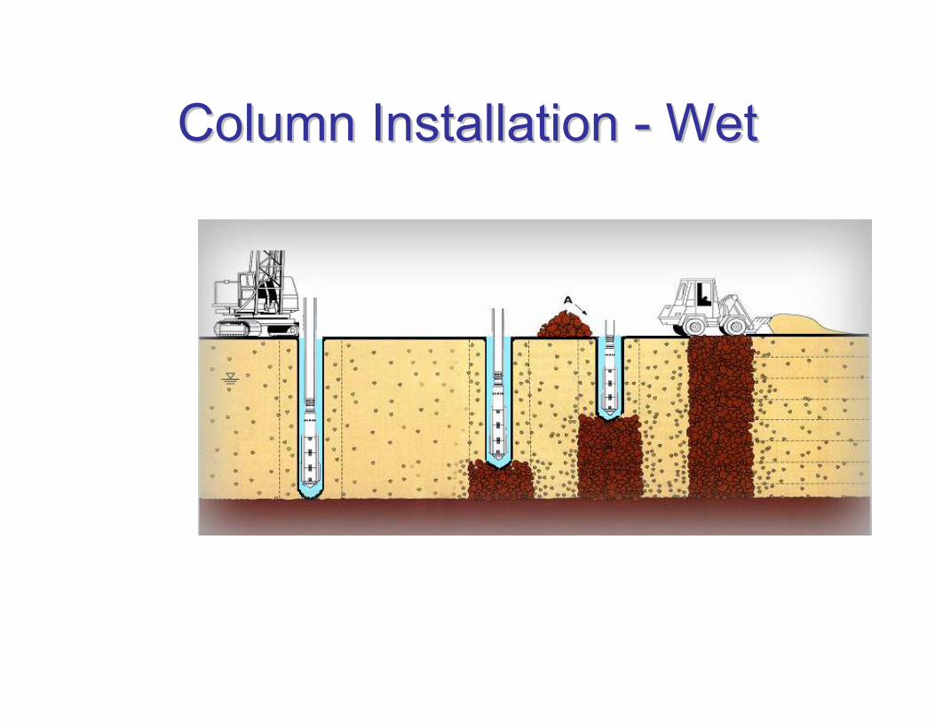
Column Installation Column Installation -- WetWet

Column Installation Column Installation -- DryDry
Differences between dry and wet
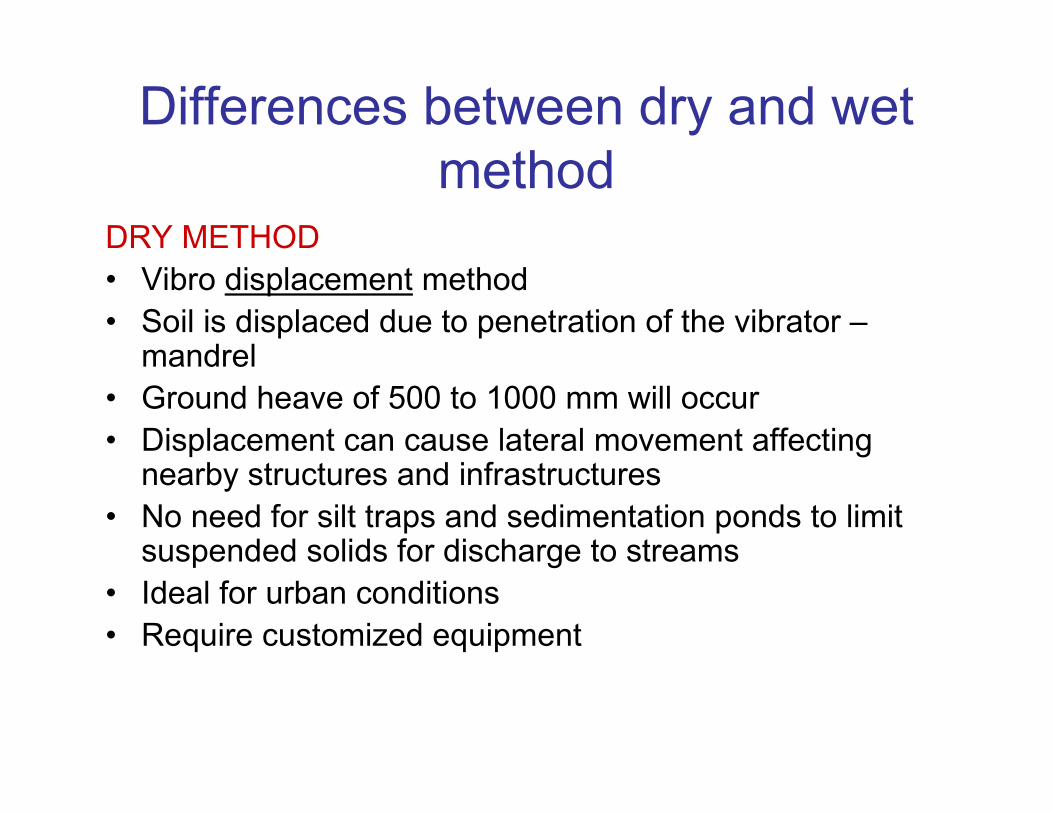
methodDRY METHOD
• Vibro displacement method
• Soil is displaced due to penetration of the vibrator –mandrel
• Ground heave of 500 to 1000 mm will occur
• Displacement can cause lateral movement affecting nearby structures and infrastructures
• No need for silt traps and sedimentation ponds to limit suspended solids for discharge to streams
• Ideal for urban conditions
• Require customized equipment
Differences between dry and wet
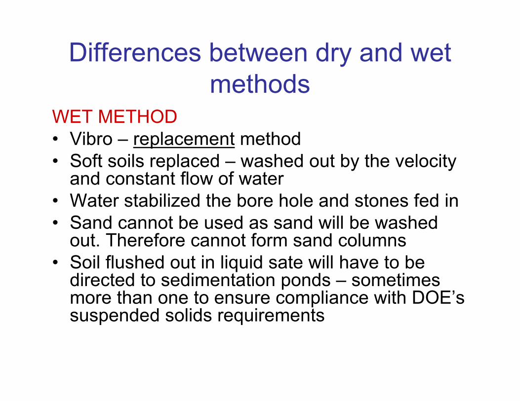
methodsWET METHOD
• Vibro – replacement method
• Soft soils replaced – washed out by the velocity and constant flow of water
• Water stabilized the bore hole and stones fed in
• Sand cannot be used as sand will be washed out. Therefore cannot form sand columns
• Soil flushed out in liquid sate will have to be directed to sedimentation ponds – sometimes more than one to ensure compliance with DOE’ssuspended solids requirements
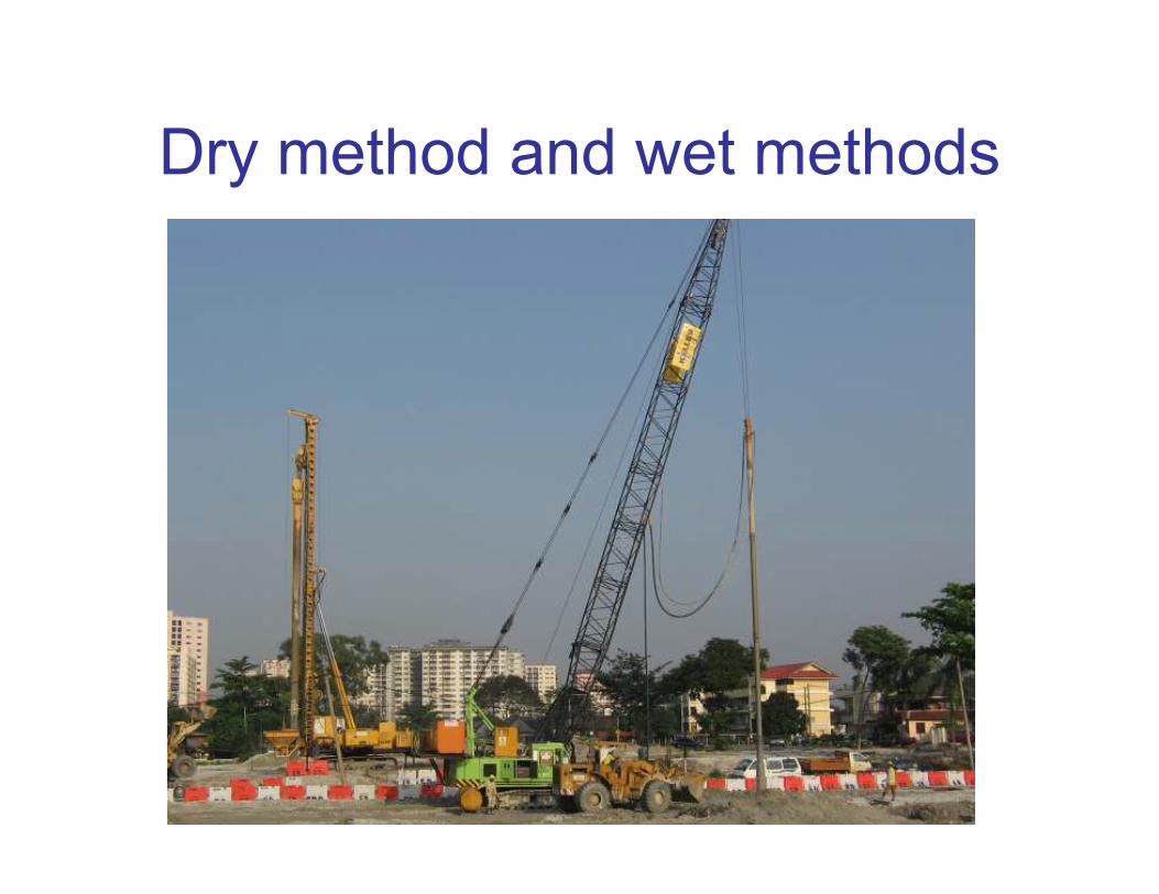
Dry method and wet methods

Placing stones into hopper – dry
method

Placing stones into hopper – dry
method
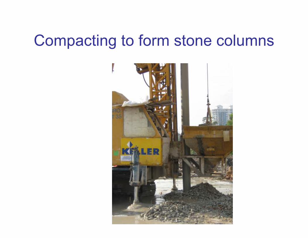
Compacting to form stone columns
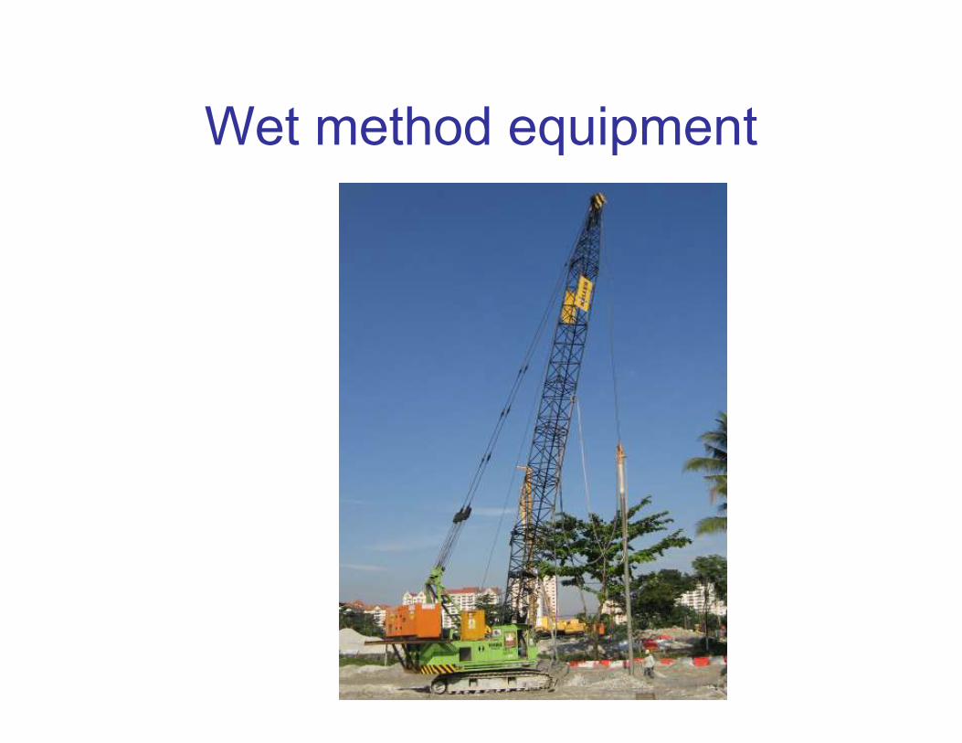
Wet method equipment

Forming stone columns wet
method
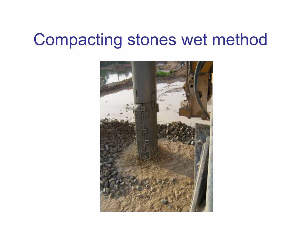
Compacting stones wet method
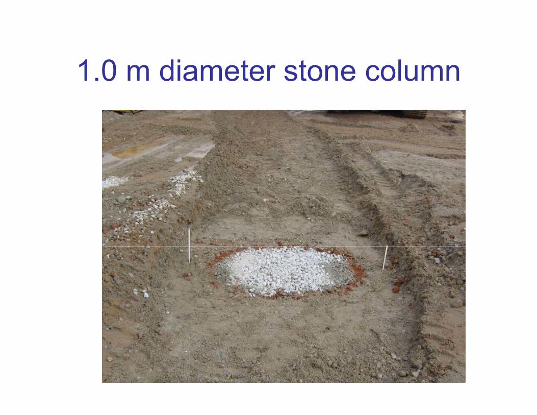
1.0 m diameter stone column
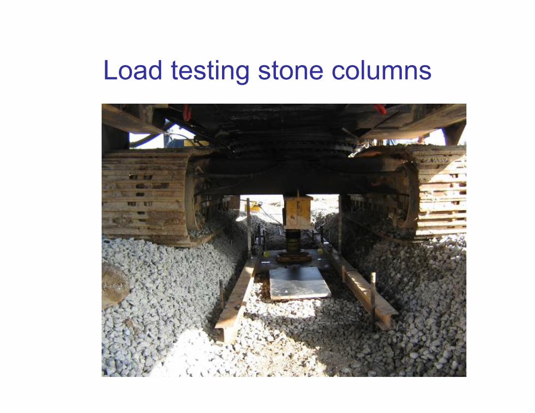
Load testing stone columns
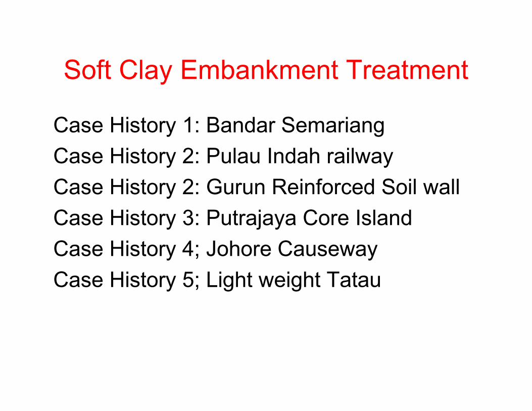
Soft Clay Embankment Treatment
Case History 1: Bandar Semariang
Case History 2: Pulau Indah railway
Case History 2: Gurun Reinforced Soil wall
Case History 3: Putrajaya Core Island
Case History 4; Johore Causeway
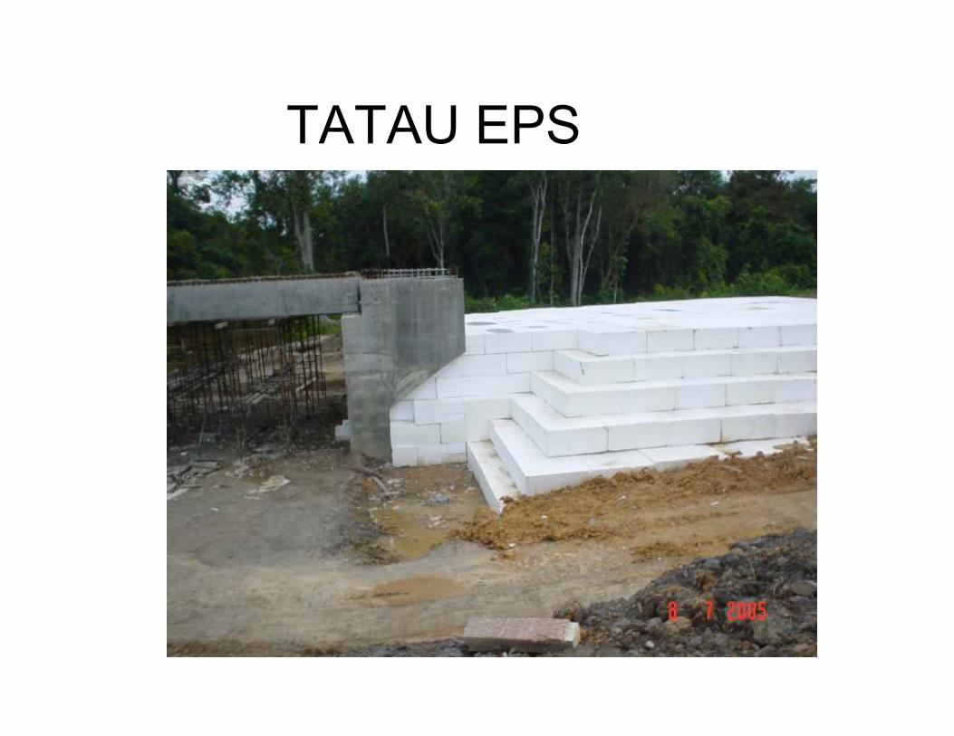
Case History 5; Light weight Tatau
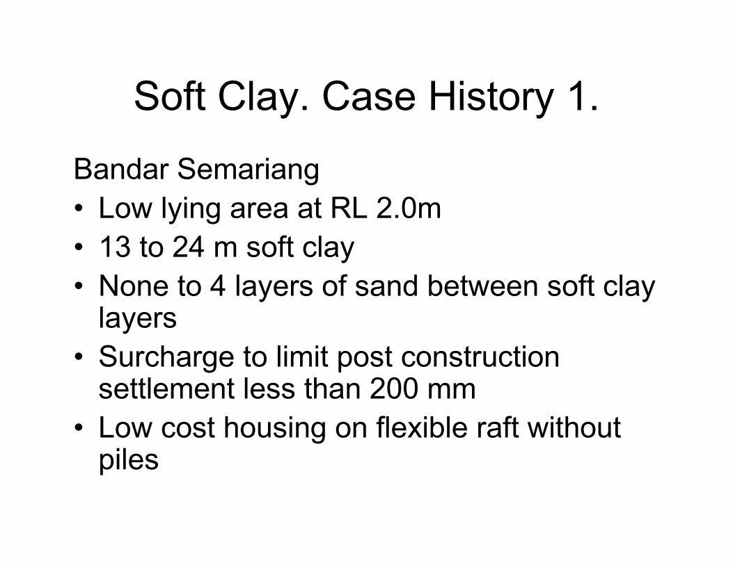
Soft Clay. Case History 1.
Bandar Semariang
• Low lying area at RL 2.0m
• 13 to 24 m soft clay
• None to 4 layers of sand between soft clay layers
• Surcharge to limit post construction settlement less than 200 mm
• Low cost housing on flexible raft without piles
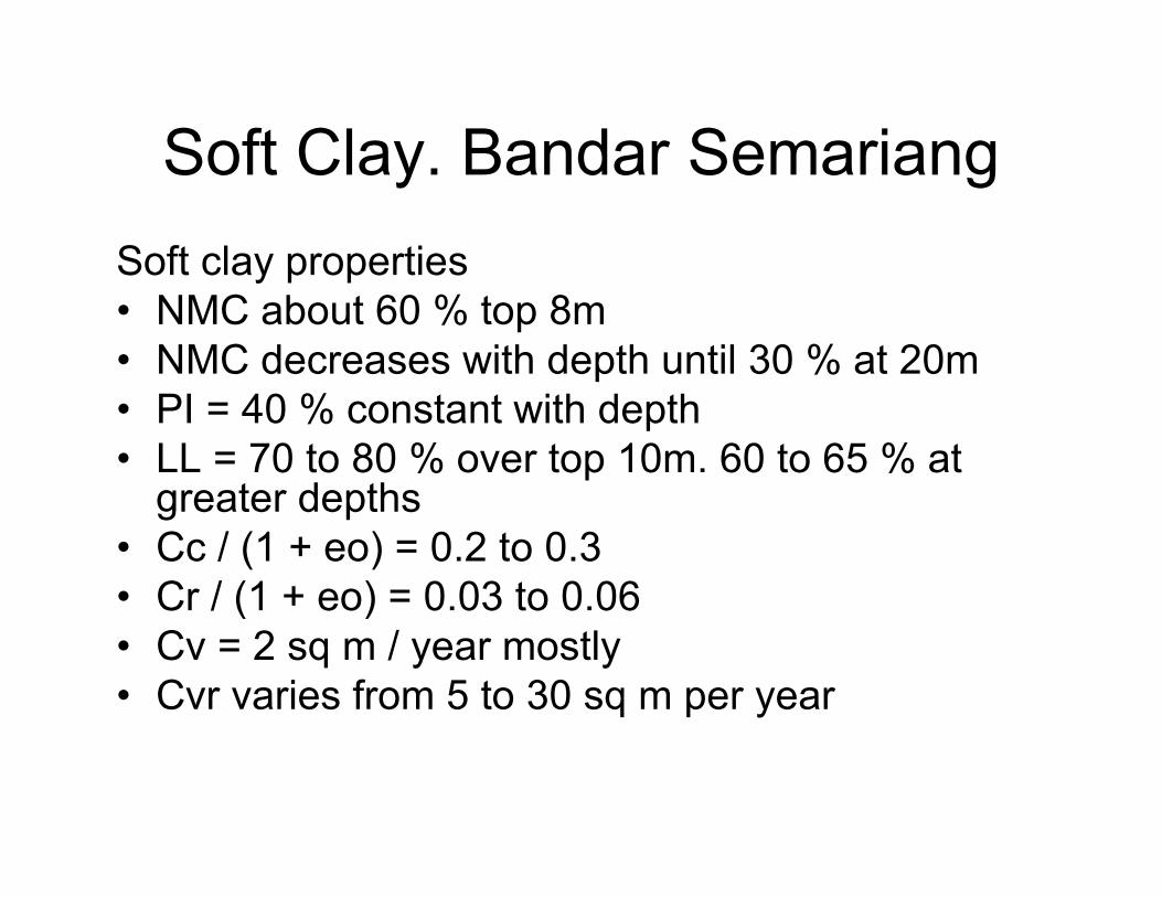
Soft Clay. Bandar Semariang
Soft clay properties
• NMC about 60 % top 8m
• NMC decreases with depth until 30 % at 20m
• PI = 40 % constant with depth
• LL = 70 to 80 % over top 10m. 60 to 65 % at greater depths
• Cc / (1 + eo) = 0.2 to 0.3
• Cr / (1 + eo) = 0.03 to 0.06
• Cv = 2 sq m / year mostly
• Cvr varies from 5 to 30 sq m per year
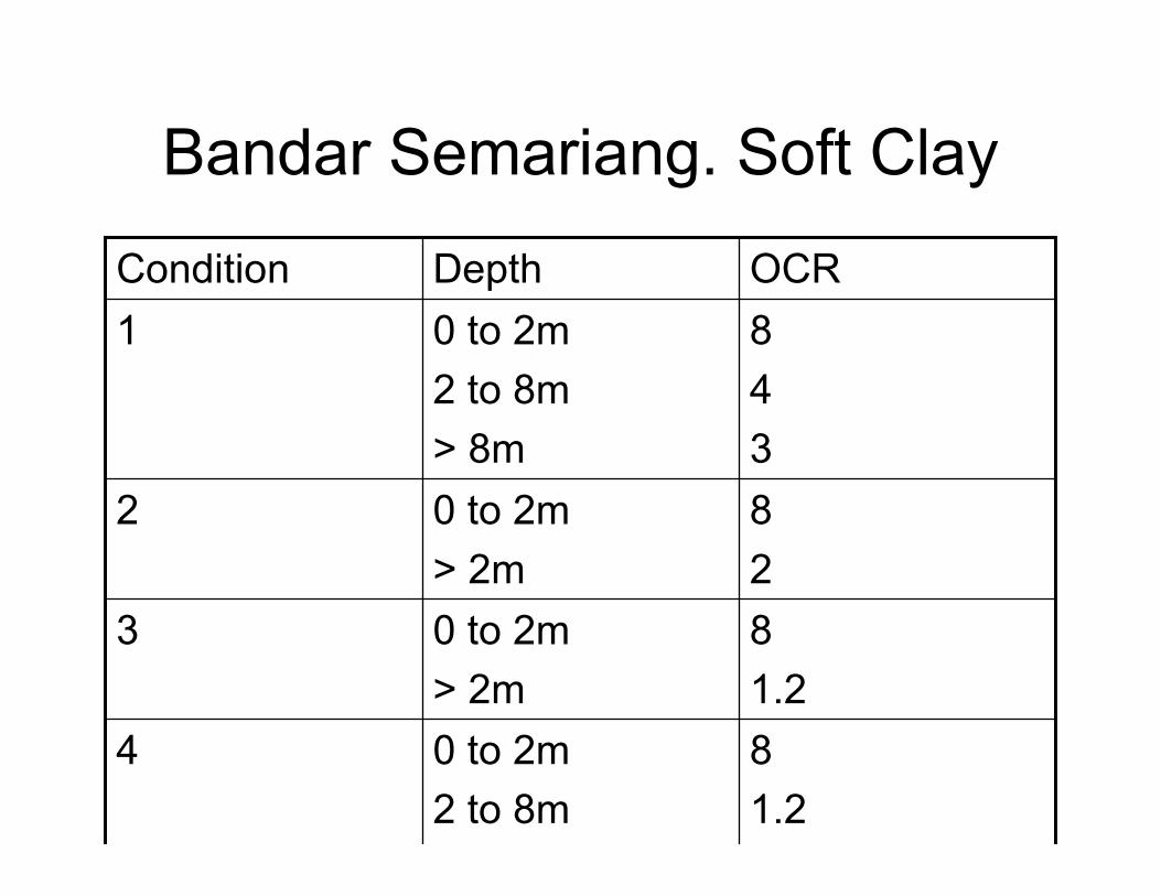
Bandar Semariang. Soft Clay
8
1.2
0 to 2m
2 to 8m
4
8
1.2
0 to 2m
> 2m
3
8
2
0 to 2m
> 2m
2
8
4
3
0 to 2m
2 to 8m
> 8m
1
OCRDepthCondition
Bandar Semariang. Soft clay
Condition 1 will have least settlement
Condition 4 will have highest settlement
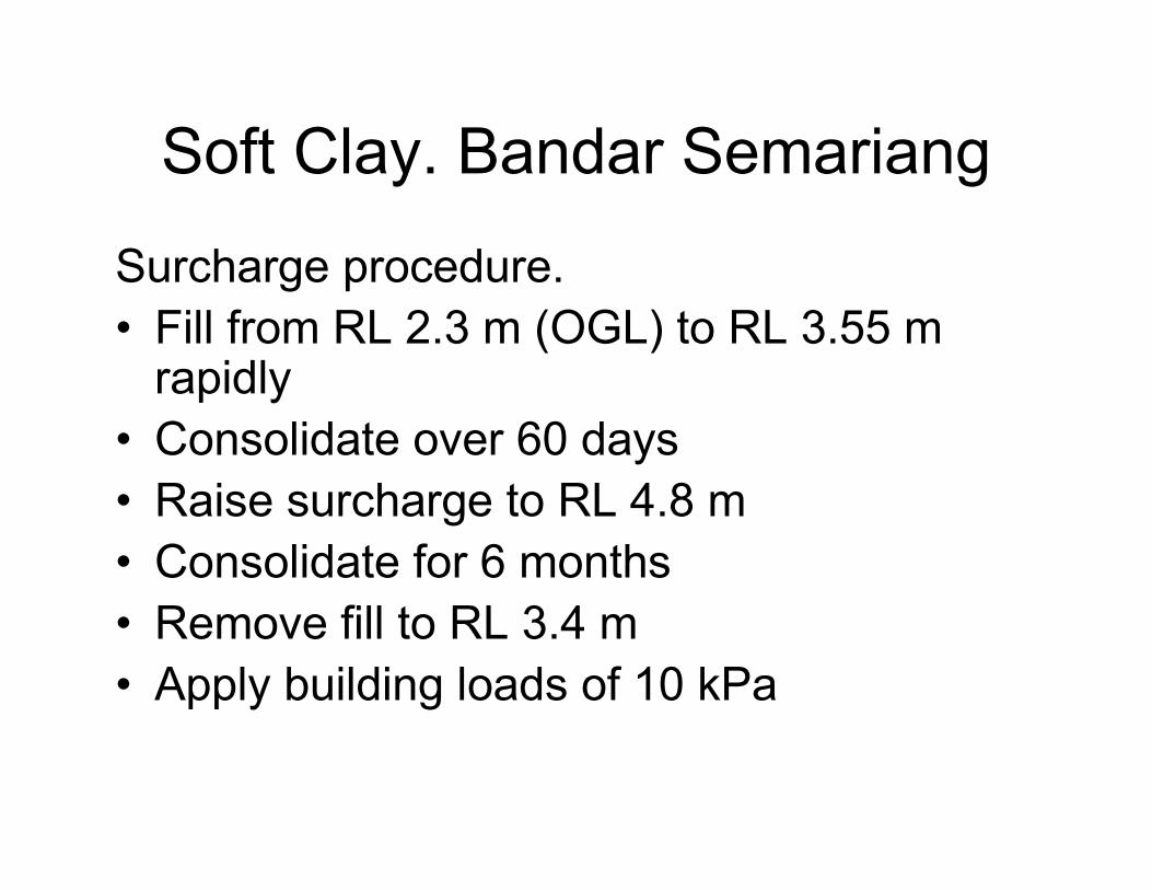
Soft Clay. Bandar Semariang
Surcharge procedure.
• Fill from RL 2.3 m (OGL) to RL 3.55 m rapidly
• Consolidate over 60 days
• Raise surcharge to RL 4.8 m
• Consolidate for 6 months
• Remove fill to RL 3.4 m
• Apply building loads of 10 kPa

Soft Clay. Bandar Semariang
Theoretical finite difference analysis.
• Soft clay thickness : 15 to 26 m
• Cvr = 5 to 30 sq m per year
• OCR Condition1
• Settlement at end of surcharge = 180 to 290 mm
• Post construction settlement = 70 to 120 mm
• Clay thickness will influence settlement only after 1 ½ years
• Heave immediately after removal surcharge. After 30 days settlement resumes
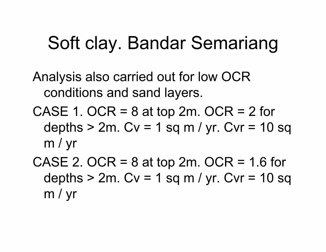
Soft clay. Bandar Semariang
Analysis also carried out for low OCR
conditions and sand layers.
CASE 1. OCR = 8 at top 2m. OCR = 2 for
depths > 2m. Cv = 1 sq m / yr. Cvr = 10 sq
m / yr
CASE 2. OCR = 8 at top 2m. OCR = 1.6 for
depths > 2m. Cv = 1 sq m / yr. Cvr = 10 sq
m / yr
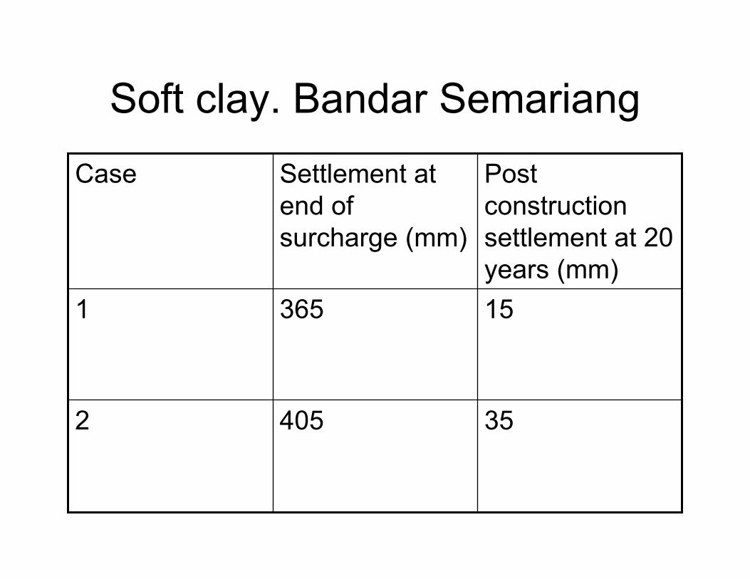
Soft clay. Bandar Semariang
354052
153651
Post
construction
settlement at 20
years (mm)
Settlement at
end of
surcharge (mm)
Case

Soft Clay. Bandar Semariang
Sand lenses cause settlement to occur
quicker. Therefore settlement during
surcharge higher. Long term settlement
lower.

Soft clay. Bandar Semariang
Settlement measurements
Set 1. Similar to Condition1. High OCR. Cvr
= 5 and 15 sq m per year
Set II. Similar to Condition1. High OCR. Cvr
= 30 sq m per year
Set III. Similar to multiple sand lenses
condition.
Soft Clay. Bandar Semariang
Surcharge area by area.
Successfully implemented.
Buildings constructed.

Soft Clay. Bandar Semariang. Cv

Soft clay. Bandar Semariang. Cvr
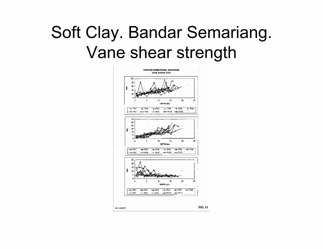
Soft Clay. Bandar Semariang.
Vane shear strength

Soft clay. Bandar Semariang.
Settlement analysis
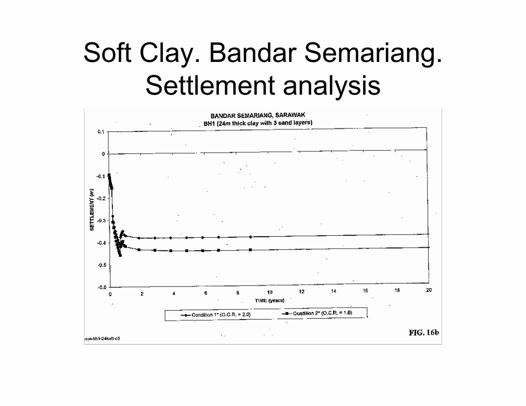
Soft Clay. Bandar Semariang.
Settlement analysis
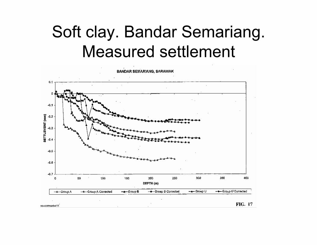
Soft clay. Bandar Semariang.
Measured settlement
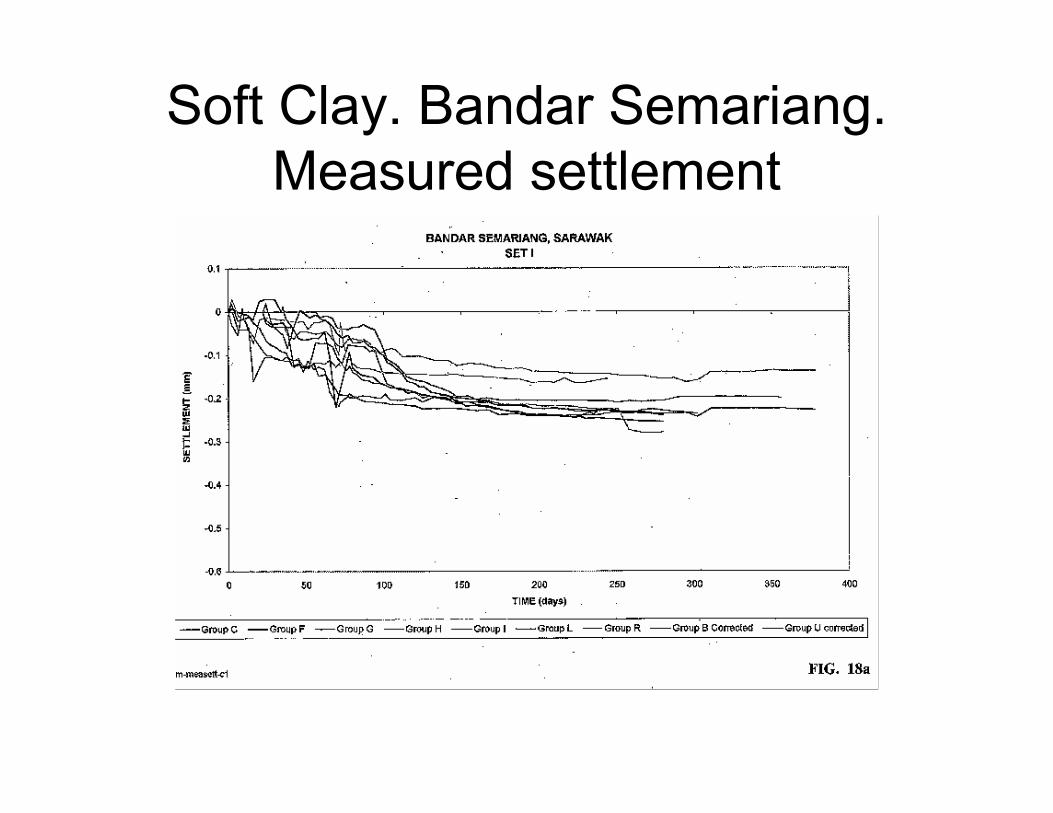
Soft Clay. Bandar Semariang.
Measured settlement

Soft Clay. Bandar Semariang.
Measured settlement

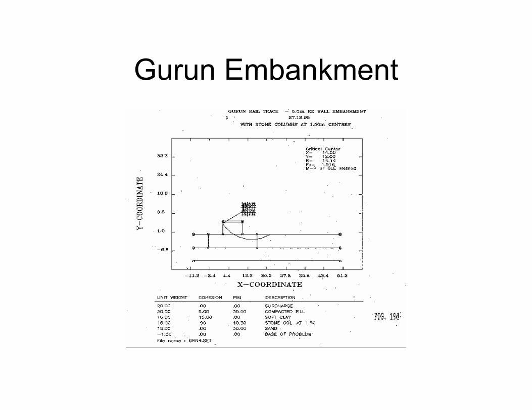
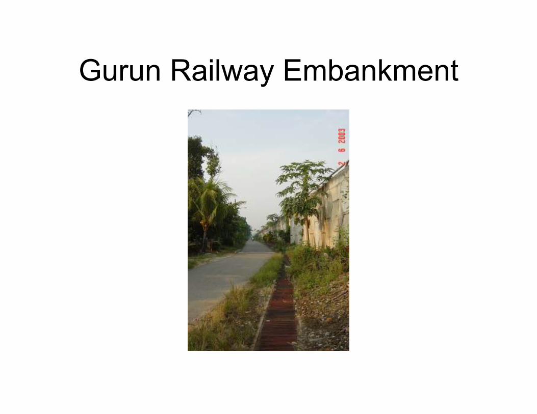
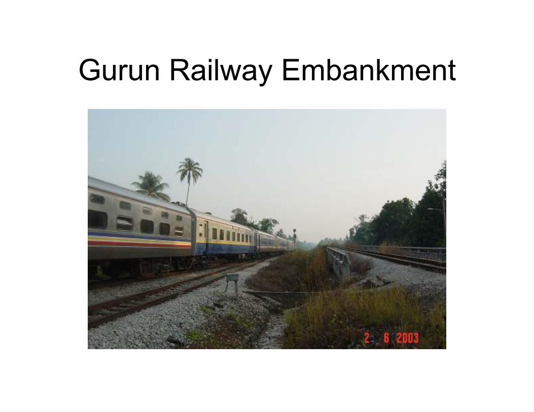
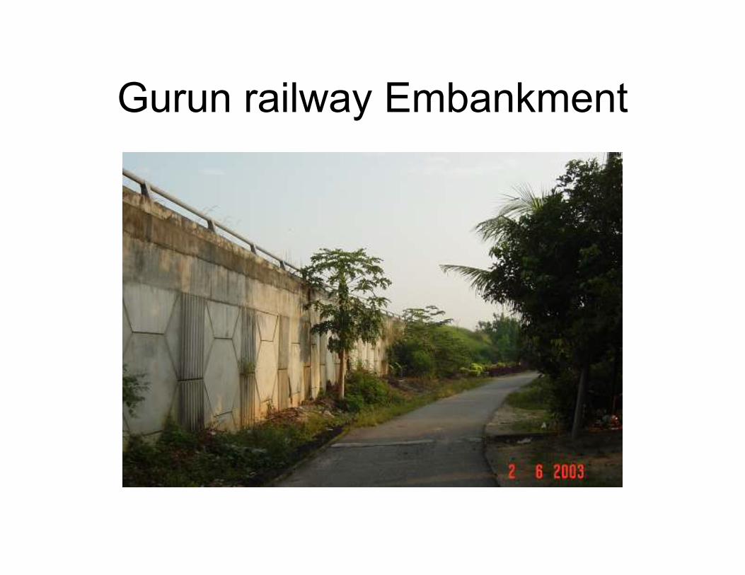
Soft Clay. Gurun Railway Wall
• Double sided Reinforced Soil wall with railway track.
• 6 m soft clay.
• Vane shear strength = 10 to 30 kpa
• OCR = 3.0
• Cc / (1 + eo) = 0.1 to 0.3
• Cv = 4 to 7 sq m /yr
• NMC = 40 %
• PI = 20 %
Soft Clay. Gurun Railway
Stabilized with stone columns

Gurun Embankment
Gurun Embankment
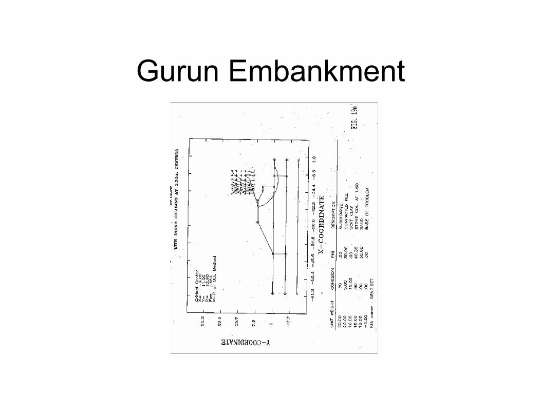
Gurun Embankment
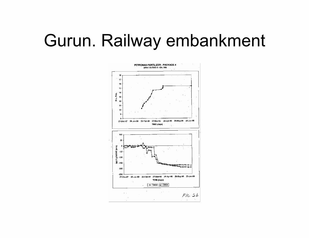
Gurun. Railway embankment

Gurun railway Embankment
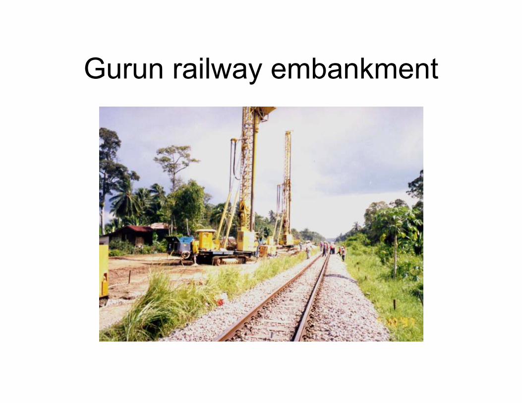
Gurun railway embankment
Gurun Railway Embankment
Gurun Railway Embankment
Gurun railway Embankment
SOFT CLAY CASE HISTORY
PUTRA JAYA CORE ISLAND.
17 m high embankment on soft clay
Soft clay average 4 to 9 m deep
Embankments to form the banks of the
Putra jaya lake
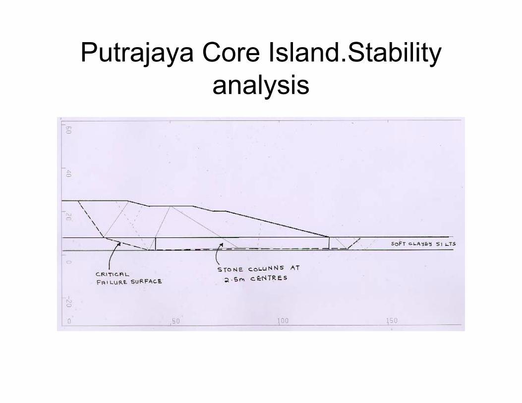
Putrajaya Core Island.Stability
analysis

.. Pi .5 r"'"" , ... , .... ~"'"
I
EMBANKMENT ON STONE COLUMNS AT BOUlEVARD; PUTRAJA YA
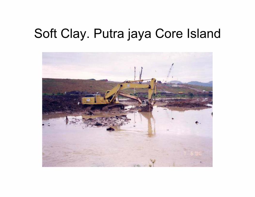
Soft Clay. Putra jaya Core Island
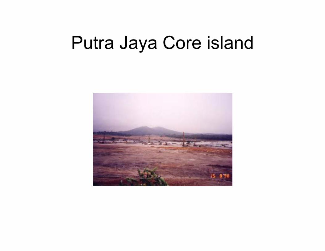
Putra Jaya Core island

Putra jaya Core Island. Stone
columns

Putra jaya Core Island. Stone
column load test

Putra jaya Stone column. Wet
method
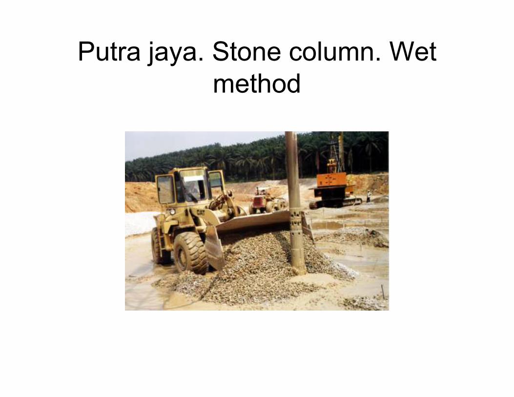
Putra jaya. Stone column. Wet
method
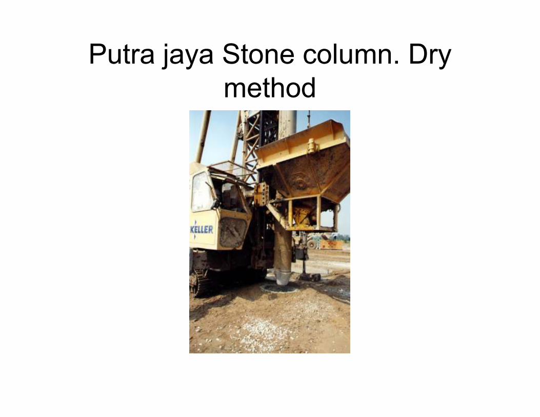
Putra jaya Stone column. Dry
method
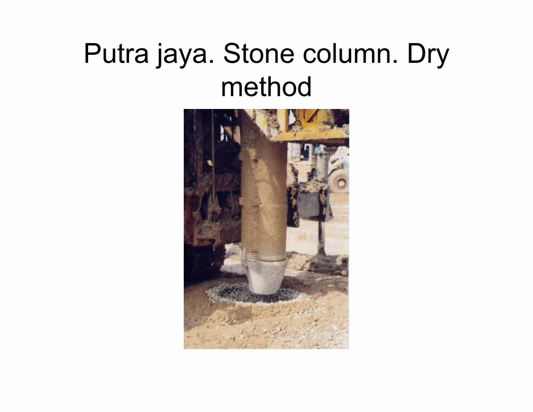
Putra jaya. Stone column. Dry
method

Putra jaya. Stone column
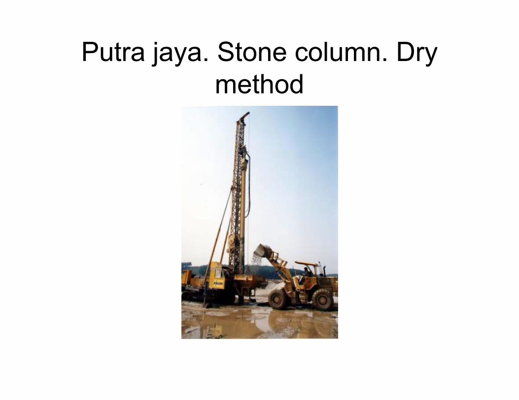
Putra jaya. Stone column. Dry
method

Putra jaya. Approach embankment
on stone column
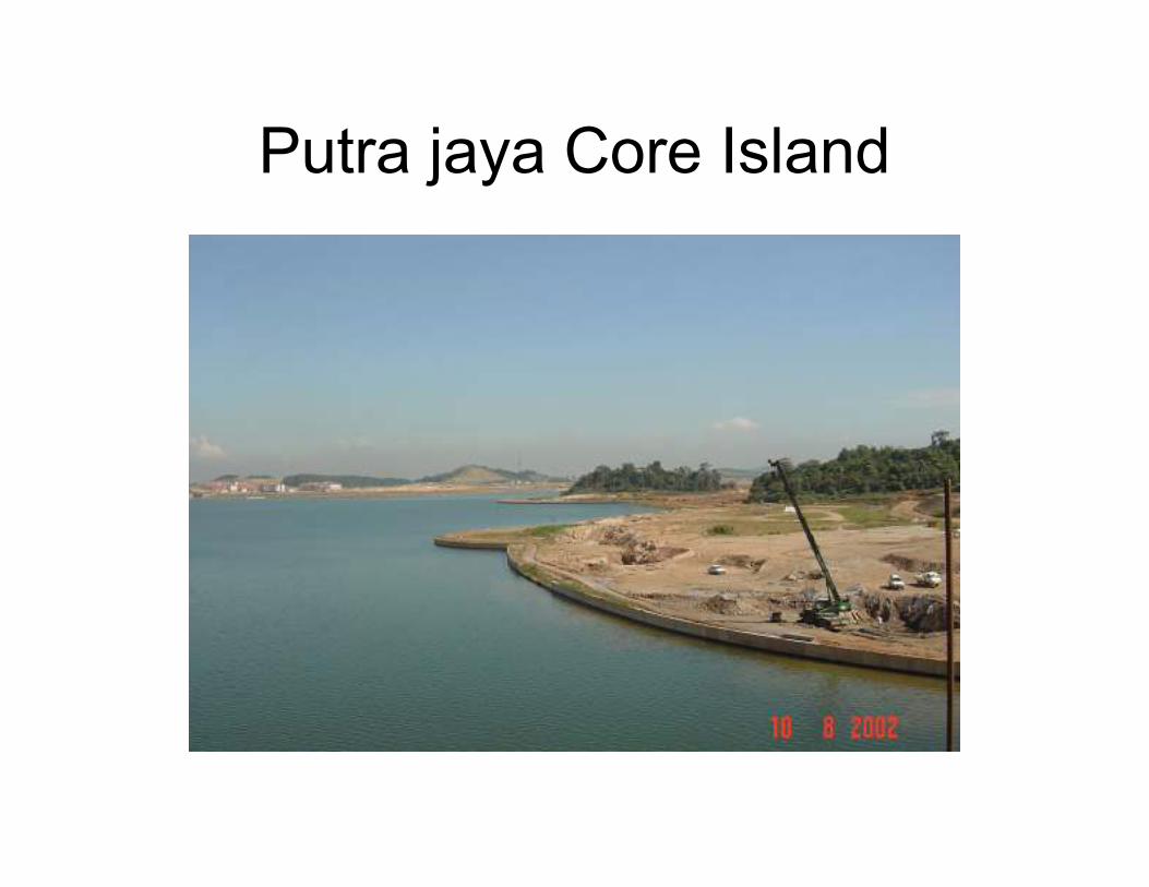
Putra jaya Core Island
SOFT CLAY CASE HISTORY
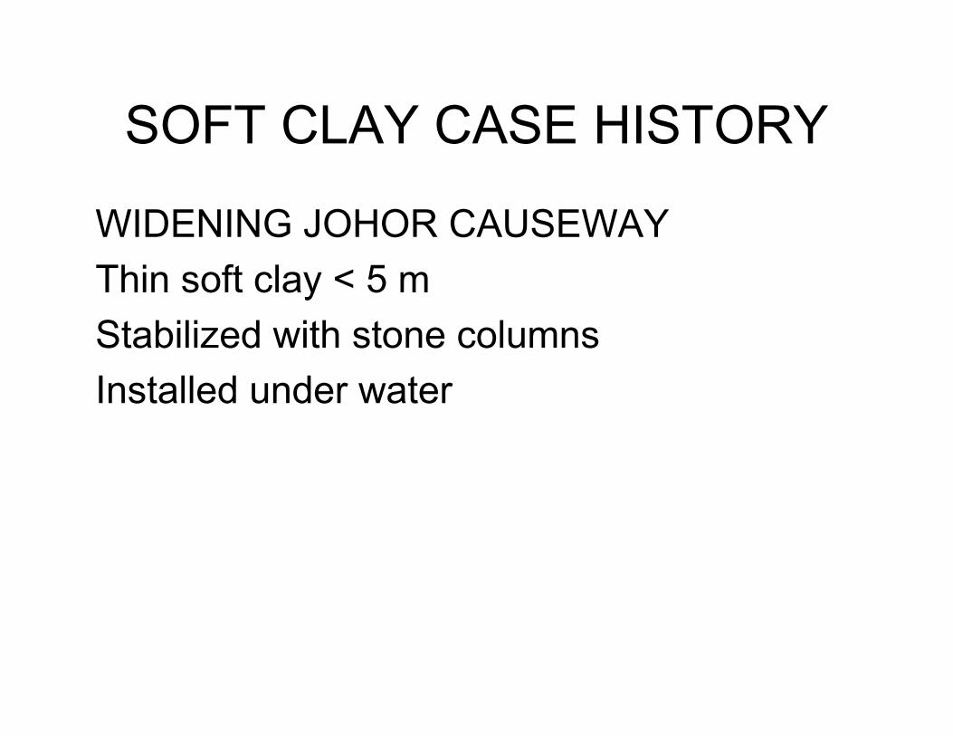
WIDENING JOHOR CAUSEWAY
Thin soft clay < 5 m
Stabilized with stone columns
Installed under water

Johore. Causeway widening.
Stone columns

JOHORE CAUSEWAY
Crane hung method stone
columns

Johore Causeway. Crane hung
method stone columns

Johore Causeway. Crane hung
method stone columns

Johore Causeway. Crane hung
method stone column
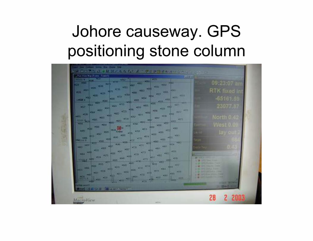
Johore causeway. GPS
positioning stone column
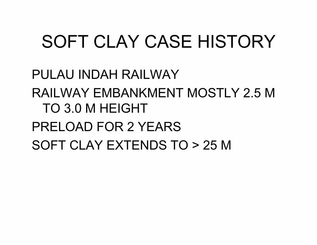
SOFT CLAY CASE HISTORY
PULAU INDAH RAILWAY
RAILWAY EMBANKMENT MOSTLY 2.5 M
TO 3.0 M HEIGHT
PRELOAD FOR 2 YEARS
SOFT CLAY EXTENDS TO > 25 M

SOFT CLAY. PULAU INDAH RAIL
Type B1 – Embankment height up to 2.0 m.
Preload without vertical drains
Type B2 – Embankment height 2 to 3 m. 10
m long prefabricated vertical drains to gain
strength for stability
Transition Pile Embankment with 175 x 175
piles at 500 cntres
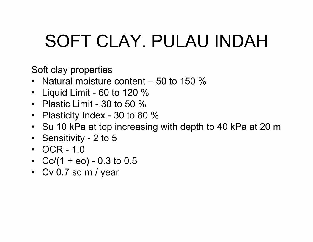
SOFT CLAY. PULAU INDAH
Soft clay properties
• Natural moisture content – 50 to 150 %
• Liquid Limit - 60 to 120 %
• Plastic Limit - 30 to 50 %
• Plasticity Index - 30 to 80 %
• Su 10 kPa at top increasing with depth to 40 kPa at 20 m
• Sensitivity - 2 to 5
• OCR - 1.0
• Cc/(1 + eo) - 0.3 to 0.5
• Cv 0.7 sq m / year
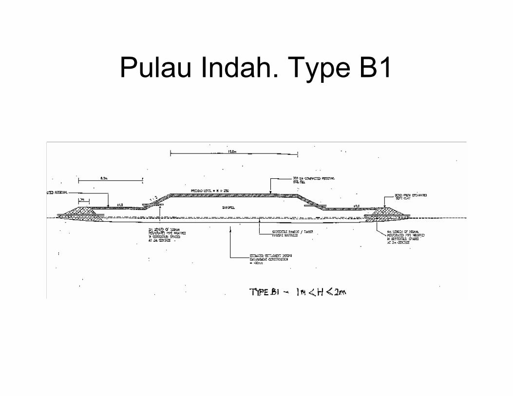
Pulau Indah. Type B1
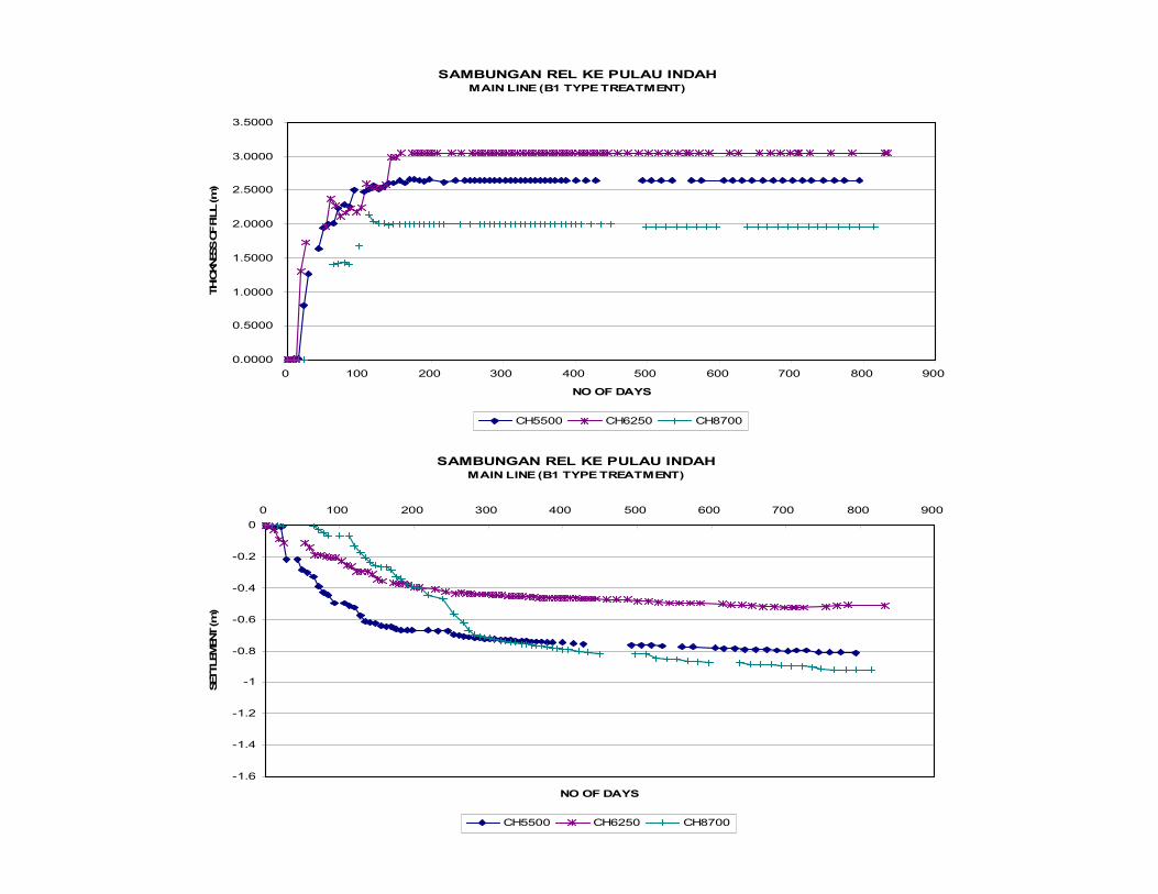
SAMBUNGAN REL KE PULAU INDAH MAIN LINE (B1 TYPE TREATMENT)
0.0000
0.5000
1.0000
1.5000
2.0000
2.5000
3.0000
3.5000
0 100 200 300 400 500 600 700 800 900
NO OF DAYS
THICKNESS OF FILL (m)
CH5500 CH6250 CH8700
SAMBUNGAN REL KE PULAU INDAH MAIN LINE (B1 TYPE TREATMENT)
-1.6
-1.4
-1.2
-1
-0.8
-0.6
-0.4
-0.2
0
0 100 200 300 400 500 600 700 800 900
NO OF DAYS
SETTLEMENT (m)
CH5500 CH6250 CH8700
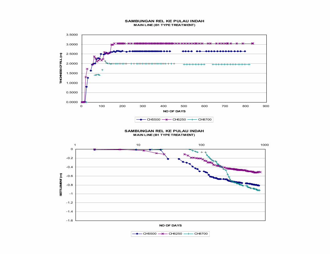
SAMBUNGAN REL KE PULAU INDAH MAIN LINE (B1 TYPE TREATMENT)
0.0000
0.5000
1.0000
1.5000
2.0000
2.5000
3.0000
3.5000
0 100 200 300 400 500 600 700 800 900
NO OF DAYS
THICKNESS OF FILL (m)
CH5500 CH6250 CH8700
SAMBUNGAN REL KE PULAU INDAH MAIN LINE (B1 TYPE TREATMENT)
-1.6
-1.4
-1.2
-1
-0.8
-0.6
-0.4
-0.2
0
1 10 100 1000
NO OF DAYS
SETTLEMENT (m)
CH5500 CH6250 CH8700
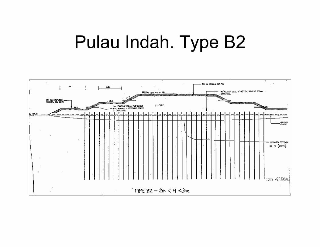
Pulau Indah. Type B2
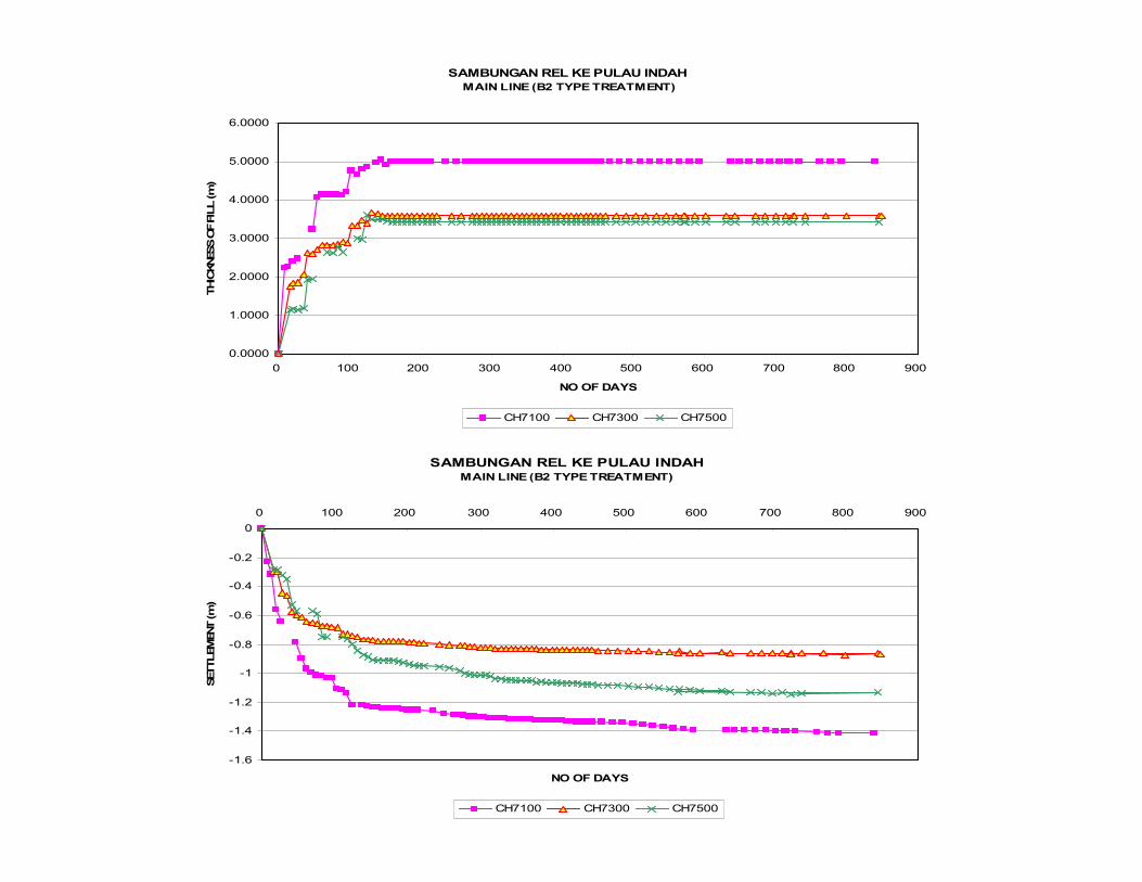
SAMBUNGAN REL KE PULAU INDAH
MAIN LINE (B2 TYPE TREATMENT)
0.0000
1.0000
2.0000
3.0000
4.0000
5.0000
6.0000
0 100 200 300 400 500 600 700 800 900
NO OF DAYS
THICKNESS OF FILL (m)
CH7100 CH7300 CH7500
SAMBUNGAN REL KE PULAU INDAH MAIN LINE (B2 TYPE TREATMENT)
-1.6
-1.4
-1.2
-1
-0.8
-0.6
-0.4
-0.2
0
0 100 200 300 400 500 600 700 800 900
NO OF DAYS
SETTLEMENT (m)
CH7100 CH7300 CH7500

SAMBUNGAN REL KE PULAU INDAH
MAIN LINE (B2 TYPE TREATMENT)
0.0000
1.0000
2.0000
3.0000
4.0000
5.0000
6.0000
0 100 200 300 400 500 600 700 800 900
NO OF DAYS
THICKNESS OF FILL (m)
CH7100 CH7300 CH7500
SAMBUNGAN REL KE PULAU INDAH MAIN LINE (B2 TYPE TREATMENT)
-1.6
-1.4
-1.2
-1
-0.8
-0.6
-0.4
-0.2
0
1 10 100 1000
NO OF DAYS
SETTLEMENT (m)
CH7100 CH7300 CH7500
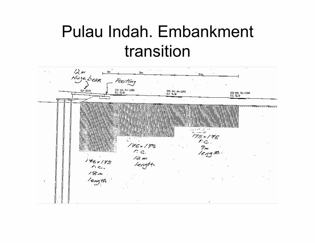
Pulau Indah. Embankment
transition
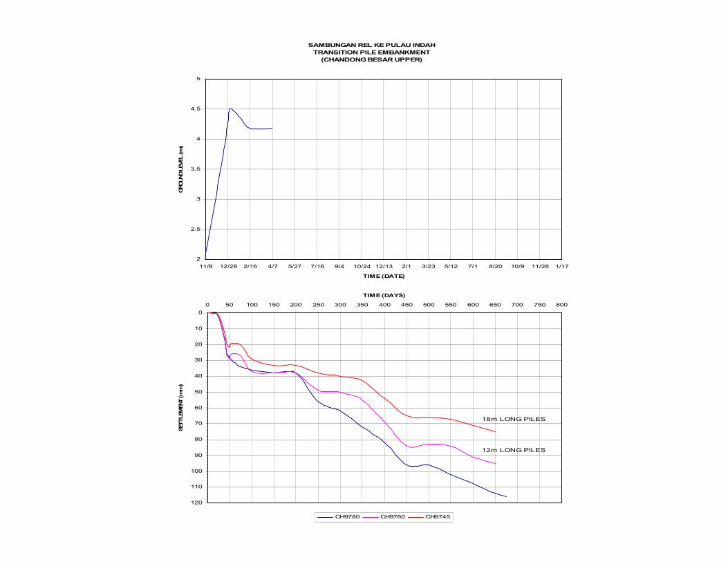
SAMBUNGAN REL KE PULAU INDAH
TRANSITION PILE EMBANKMENT
(CHANDONG BESAR UPPER)
2
2.5
3
3.5
4
4.5
5
11/8 12/28 2/16 4/7 5/27 7/16 9/4 10/24 12/13 2/1 3/23 5/12 7/1 8/20 10/9 11/28 1/17
TIME (DATE)
GROUND LEVEL (m)
0
10
20
30
40
50
60
70
80
90
100
110
120
0 50 100 150 200 250 300 350 400 450 500 550 600 650 700 750 800
TIME (DAYS)
SETTLEMENT (mm)
CH9780 CH9760 CH9745
12m LONG PILES
18m LONG PILES
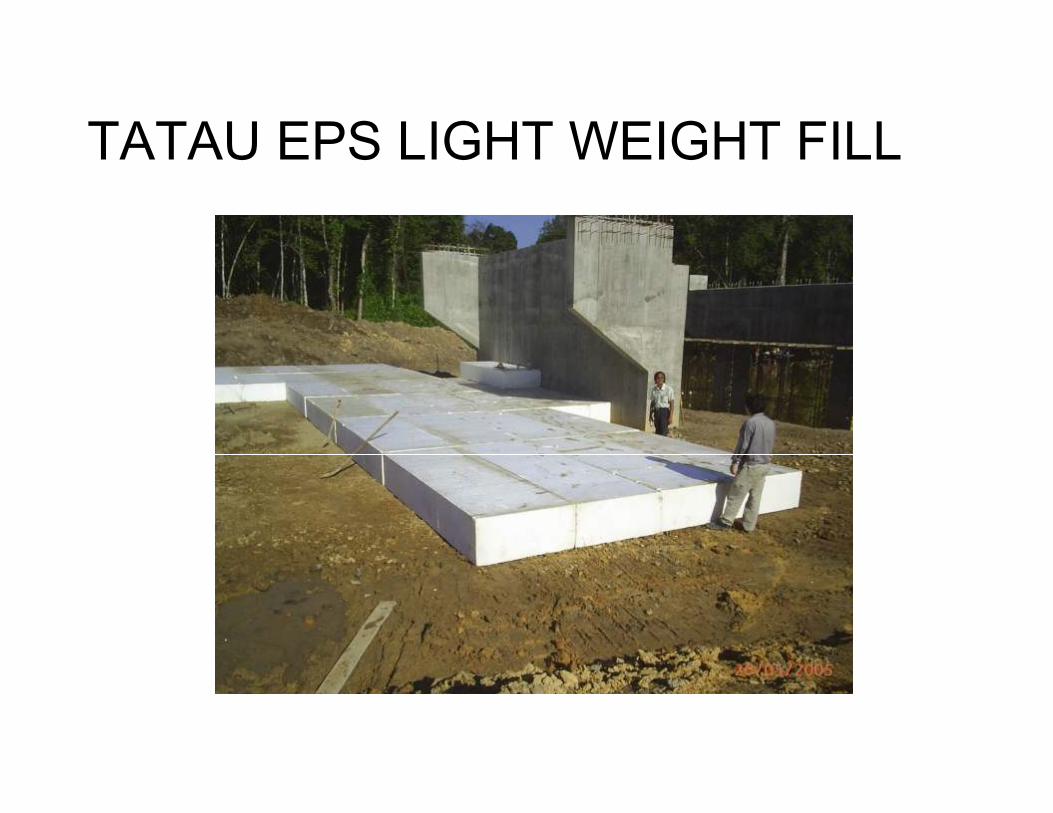
TATAU EPS LIGHT WEIGHT FILL
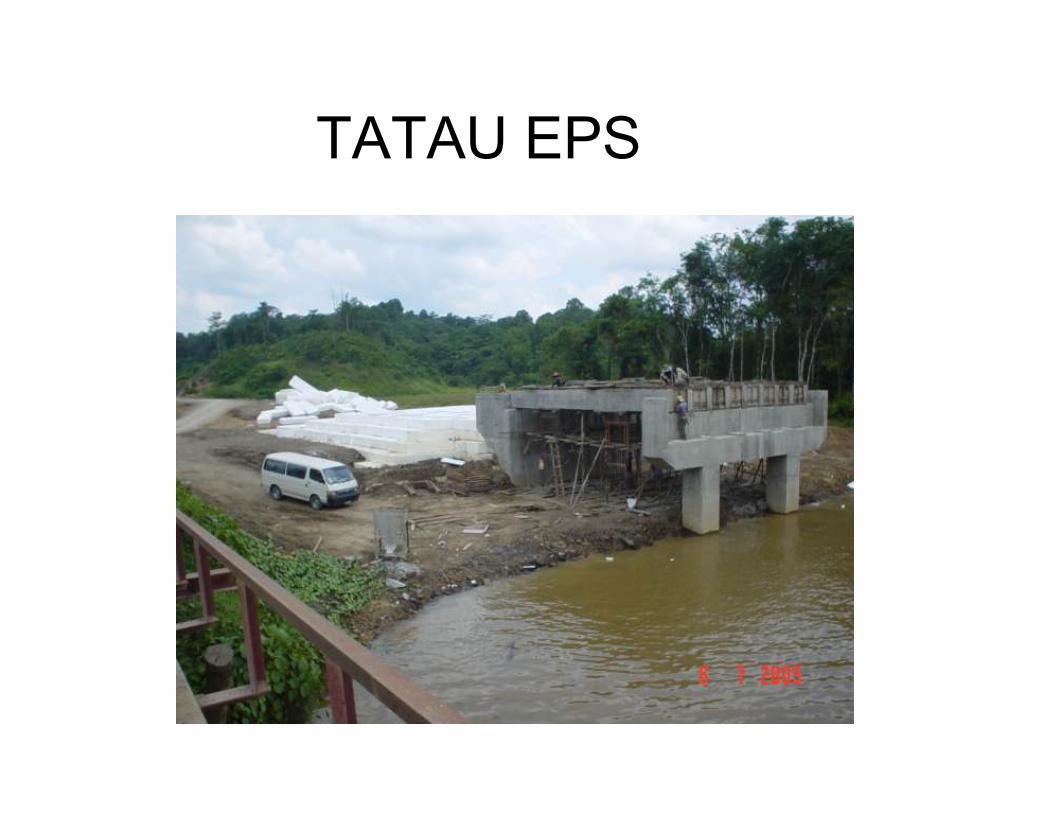
TATAU EPS
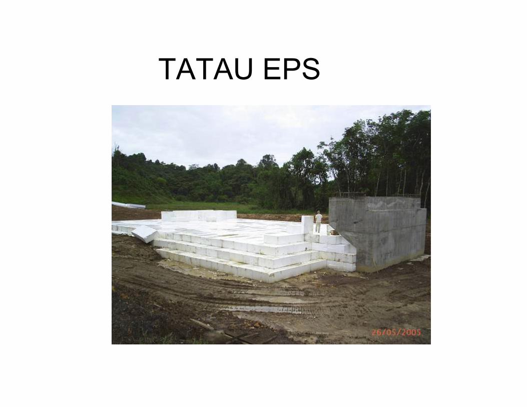
TATAU EPS

TATAU EPS
TATAU EPS
END OF LECTURE
THANK YOU