working in roads and trench construction
TRANSCRIPT

Version: 12 November 2012 Page 1 of 32
Engineering Appendix Four
Working in Roads and Trench Construction
1. INTRODUCTION ........................................................................................................... 3
2. PLANNING AND COORDINATION .............................................................................. 3
2.1 Liaison Meetings ............................................................................................................................................ 3
2.2 General Requirements for Location of Utility Services ................................................................................... 4
3. CORRIDOR ACCESS REQUEST (CAR) ...................................................................... 5
3.1 Lodgement of the CAR ................................................................................................................................... 5
3.2 Receipt and Evaluation of the CAR ................................................................................................................. 5
3.3 Information to be Provided with the CAR ...................................................................................................... 6
3.4 Major Works .................................................................................................................................................. 6
3.5 Works Access Permit ...................................................................................................................................... 7
3.6 Works Completion ......................................................................................................................................... 7
3.7 Warranty Period ............................................................................................................................................ 8
3.8 Completion of Maintenance Period ............................................................................................................... 8
3.9 Public Liability ................................................................................................................................................ 8
3.10 Emergency Contact Details ............................................................................................................................. 9
4. GENERAL REQUIREMENTS ....................................................................................... 9
4.1 Protection of Existing Assets (Road, Utility Structures, Survey Marks) ........................................................... 9
4.2 Maintaining Stormwater Networks ...............................................................................................................10
4.3 Trenchless Construction ................................................................................................................................11
4.4 Working in the Vicinity of Trees ....................................................................................................................11
5. LOCATING EXISTING UNDERGROUND UTILITY STRUCTURES........................... 12
5.1 General Procedures for Location ...................................................................................................................12
5.2 Finding Unmarked Assets owned by Others ..................................................................................................13
5.3 Locating Traffic Signal Assets ........................................................................................................................13
Working in Roads and Trench Construction
--> _ref <-- ### Invalid Field Definition ### --> _format <-- ### Invalid Field Definition ###
Version: 12 November 2012 Page 2 of 32
6. SITE MANAGEMENT ................................................................................................. 14
6.1 General .........................................................................................................................................................14
6.2 Pollution Control ...........................................................................................................................................14
6.3 Traffic Management ......................................................................................................................................14
6.4 Hours of Work ...............................................................................................................................................15
6.5 Noise and Vibration Management ................................................................................................................15
6.6 Public Relations and Communication ............................................................................................................15
6.7 Signage for Works in Transport Corridors .....................................................................................................16
7. PROCEDURES FOR UNDERTAKING EMERGENCY WORKS................................. 17
8. TRENCHING PROCEDURES ..................................................................................... 17
8.1 General .........................................................................................................................................................17
8.2 Trench Cutting and Excavation ......................................................................................................................17
8.3 Backfill Materials ..........................................................................................................................................20
8.4 Backfill Placement and Compaction ..............................................................................................................21
8.5 Compaction Testing ......................................................................................................................................23
9. SURFACE LAYER REINSTATEMENT ....................................................................... 24
9.1 General Requirements ..................................................................................................................................24
9.2 Reinstatement near a Joint or Edge ..............................................................................................................25
9.3 Trench Reinstatement in Driveways ..............................................................................................................26
9.4 Temporary Surface Reinstatement ................................................................................................................26
9.5 Specific Requirements for Different Surface Types........................................................................................27
9.6 Special Paving, Amenity Areas and Decorative Areas ....................................................................................29
9.7 Road Markings, Signs and Furniture ..............................................................................................................29
9.8 Trench Excavation in Grassed Areas ..............................................................................................................30 9.8.1 General ............................................................................................................................................................ 30 9.8.2 Compaction ..................................................................................................................................................... 31 9.8.3 Grass Seed ....................................................................................................................................................... 31
10. BONDS ....................................................................................................................... 31
Drawing 1 ..................................................................................................................................................................32
Working in Roads and Trench Construction
--> _ref <-- ### Invalid Field Definition ### --> _format <-- ### Invalid Field Definition ###
Version: 12 November 2012 Page 3 of 32
1. INTRODUCTION
All works including road closures for street parades, designated parking space temporarily unavailable, work on footpaths, vehicle crossing construction, tree work, scaffolding and crane work within roads must have a Works Access Permit (WAP). This must be approved by Horowhenua District Council and/or the New Zealand Transport Agency for State Highways. Council is using the National Code of Practice for Utility Operator's Access to Transport Corridors effective from 1 January 2012 as the basis for access to the roading network. Some of these requirements have been modified in this document to localise the National Code for Council use.
2. PLANNING AND COORDINATION
For work in or on roads all Parties should cooperate, collaborate and engage with each other constructively through open communication and maintain formal and informal communications. The Horowhenua District Council Roading Services Manager shall:
a) coordinate works in the Transport Corridor including providing advice on other Parties’ Planned Works programmes and leading coordination meetings;
b) set Reasonable Conditions for any Works in the Transport Corridor which are consistent with the National Code; and
c) ensure and enforce compliance with these Conditions and with the Code. The Horowhenua District Council Corridor Manager shall:
d) receive and process notifications of proposed Works in the Transport Corridor; Where State highways pass through urban areas, the Corridor Manager's role may be split between the NZTA and Council. In this instance, the point of contact is the NZTA and it is the responsibility of the NZTA to coordinate the response. The Utility Operator (including Council's Water, Wastewater and Stormwater installations) must:
e) notify the Roading Services Manager of any Planned Works in the Transport Corridor, in a wider planning sense, and notify the Corridor Manager (through the "beforeUdig CAR Manager" service) in relation to specific Works,
f) comply with the National Code and with any reasonable conditions set by the Corridor Manager in relation to its Works, and
g) participate as required in coordination and liaison meetings.
2.1 Liaison Meetings
The Roading Services Manager holds 3-4 month liaison meetings:
a) These meetings are to improve coordination and planning of activities in the Transport Corridor between all Parties.
b) Additional strategic high level planning meetings will be held to discuss annual plans, longer term planning and coordination.
Working in Roads and Trench Construction
--> _ref <-- ### Invalid Field Definition ### --> _format <-- ### Invalid Field Definition ###
Version: 12 November 2012 Page 4 of 32
The primary objective of the liaison meetings is to share information and coordinate work programmes to minimise disruption and damage during Works. A person of appropriate authority should represent each Party at the meetings. Liaison meetings are also an opportunity to discuss matters such as:
c) further simplification of processes for Works that do not require opening or breaking up a Road or that are on a low Traffic volume road;
d) processes for dealing with emergency situations in Transport Corridors;
e) consideration of opportunities to use or remove redundant or abandoned assets, and/or to install ducts for future use;
f) processes for working around trees;
g) the development of Corridor Management Policy, frameworks or procedures to ensure coordinated outcomes are achieved that address all Parties’ needs;
h) consideration of issues relating to ‘lifelines’ co-location (for example, where having a number of highly critical assets in the same Transport Corridor creates a point of significant vulnerability);
i) working together to enable development within the Transport Corridor, such as consideration of relocation of Utility Structures where appropriate and practicable.
The Roading Services Manager should liaise with all Council officers in relation to any other requirements (such as safety, parks, reserves, trees) with respect to working in the Transport Corridor.
2.2 General Requirements for Location of Utility Services
a) Where practicable, Utility Services must be positioned in the Transport Corridor:
as close as possible to the property boundary.
in an area designated for, or already used by, Utility Services.
parallel or perpendicular to the Road centreline (to ensure that new Work does not intrude into space that could inhibit future use by others).
outside the Carriageway (particularly where the operating speed is greater than 70km/h).
with at least 300mm separation, and ideally with 1m separation, from the kerb and channel or vertical front face of a catch pit, sump or subsoil drainage area, leaving this area free for its land drainage function.
to maintain the following minimum footpath widths: 1.5m in residential areas, 2.5m in Commercial Areas, and 1.8m (3m preferred) for combined foot/cycle paths.
b) The location of services shall be approved by the Corridor Manager.
c) In identifying the proposed Utility Service location the following should be considered:
spacing and location in accordance with the statutory and declared operational requirements of Utility Operators and Council (such as subdivision standards, NZS 4404 Land Development and Subdivision Infrastructure or Council Drawing 1 attached).
using the preferred lay position, which is the ‘back Berm’ (where the front Berm is the zone between the kerb and the footpath and the back Berm is the remainder of the area to the property boundary).
Working in Roads and Trench Construction
--> _ref <-- ### Invalid Field Definition ### --> _format <-- ### Invalid Field Definition ###
Version: 12 November 2012 Page 5 of 32
best use of available underground space, such as installing multiple ducts in a vertical configuration where it is practicable and not likely to cause conflict between longitudinal and lateral lines.
minimising effects on existing above-ground Utility Services, trees and street furniture.
not unreasonably inhibiting the free flow of Traffic, including pedestrians, especially on busy Roads (consideration should be given to using less busy Roads).
placing bulk Utility Services beneath the Carriageway outside of wheel track alignments in urban areas (to free Berm space for other Utility Structures).
positioning Utility Services so that access to maintain and develop the network can be undertaken while minimising the effect on Traffic.
minimising the number of transverse crossings in the Transport Corridor.
minimising impacts on other Utility Operators and property owners and occupiers.
coordinating Works with other Parties.
avoiding Roads with high speeds, Traffic volumes or of other significance to one of the Parties for some reason (more appropriate in a Greenfields situation).
The risks of land stability or earth movement, if placing Utility Services in embankments (specialist technical investigation may be required).
Duct colours for the different Utility Services must be in accordance with the guidelines as specified in Clause 34 of the Department of Labour Guide for Safety with Underground Services (2002).
3. CORRIDOR ACCESS REQUEST (CAR)
3.1 Lodgement of the CAR
a) The Corridor Access Request (CAR) constitutes formal notice of intention to carry out Works in the Transport Corridor.
b) The number of CAR applications required must be the minimum to efficiently achieve the co-ordination of Works between Parties.
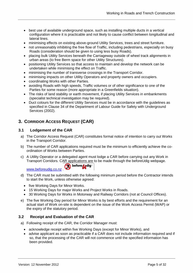
c) A Utility Operator or a delegated agent must lodge a CAR before carrying out any Work in Transport Corridors. CAR applications are to be made through the beforeUdig webpage.
www.beforeudig.co.nz
d) The CAR must be submitted with the following minimum period before the Contractor intends to start the Work, unless otherwise agreed:
five Working Days for Minor Works.
15 Working Days for major Works and Project Works in Roads.
30 Working Days for Works in Motorway and Railway Corridors (not at Council Offices).
e) The five Working Day period for Minor Works is by best efforts and the requirement for an actual start of Work on-site is dependent on the issue of the Work Access Permit (WAP) or the expiry of the statutory period.
3.2 Receipt and Evaluation of the CAR
a) Following receipt of the CAR, the Corridor Manager must:
acknowledge receipt within five Working Days (except for Minor Works), and
advise applicant as soon as practicable if a CAR does not include information required and if so, that the processing of the CAR will not commence until the specified information has been provided.
Working in Roads and Trench Construction
--> _ref <-- ### Invalid Field Definition ### --> _format <-- ### Invalid Field Definition ###
Version: 12 November 2012 Page 6 of 32
b) Following receipt of the full information required for the CAR, the Corridor Manager must:
advise the Utility Operator or Contactor of the reasonable conditions for access to the road as soon as practicable and no later than the timeframes stated above.
3.3 Information to be Provided with the CAR
a) A Utility Operator or Contractor must submit the following information with a CAR for Major Works and Project Works:
A site-specific Traffic Management Plan (TMP) that:
is approved by a suitably qualified person, as defined in NZTA manuals, and accepted by
the Corridor Manager.
demonstrates that safety and other impacts on road users and workers are protected.
complies with CoPTTM for State Highways and the Local Roads Supplement for Local
Roads and any special requirements of the Corridor Manager.
A Plan indicating the proposed scope and scale of the Works, including depth and route of
proposed Utility Structures and the location of nearby Utility Structures, kerbs, footpaths,
trees and street furniture;
Details of other Utility Operators that may be affected and evidence they have been
consulted;
Details of when the Work is scheduled including times of day as well as dates; and
Proposed location of any chambers or above-ground Utility Structures.
b) Additional information may be required when:
the location of the Work Site moves to a position not described on the WAP or CAR, or
the Utility Operator does not complete the Works within six months of the issue of the WAP (or other period agreed between the Parties).
3.4 Major Works
Means maintenance or construction Work in, on, along, over, across or under the Transport Corridor, which includes Works undertaken in any of the following situations:
a) A Trench extending more than 20m along the Road.
b) A traffic lane needing to be closed on a Arterial or Collector Road.
c) A Road closed for more than two minutes during peak Traffic, or business hours in Central Business Districts.
d) Work affecting metered parking or other restricted parking areas for more than two hours during normal business hours.
e) Work affecting a Road Structure such as a bridge, tunnel, or retaining wall.
f) Work needing to be done outside normal hours of work.
g) Work restricting property access for more than ten minutes for business or one hour for residential.
h) Diverting a footpath for more than eight hours.
i) A financial contribution is sought from the Roading Services Manager, such as towards the reinstatement of the road surface.
Working in Roads and Trench Construction
--> _ref <-- ### Invalid Field Definition ### --> _format <-- ### Invalid Field Definition ###
Version: 12 November 2012 Page 7 of 32
Notwithstanding these specific criteria, where, due to the scope, location, time, or duration of the Works, the Corridor Manager and Utility Operator or Contractor agree that the Works cause minimal inconvenience to users of the Transport Corridor, the Works will be considered to be Minor Works.
3.5 Works Access Permit
The Utility Operator and/or Contractor must:
a) not start the Work until a WAP has been issued or until 15 Working Days after the CAR is lodged, whichever comes first subject to acknowledgement that the CAR was lodged,
b) ensure that all Works comply with the conditions of the WAP, and approved TMP, issued for those Works,
c) keep a copy of the WAP, including conditions, on-site while Work is being carried out, and
d) complete the Works within six months of issue of the WAP.
3.6 Works Completion
As soon as practicable but within ten Working Days of the completion of all Work for which a WAP has been issued, the Utility Operator and/or Contractor must inform the Corridor Manager that the works have been completed. The Utility Operator and/or Contractor notify the following;
a) Any amendments to information supplied on the original CAR, as necessary to describe accurately the location and extent of the work.
b) Quality assurance records or certification. c) A written statement confirming that the completed Works fully comply with the conditions
imposed by the WAP, signed by a person authorised to bind the Utility Operator. d) Details of any outstanding Work that the Utility Operator has agreed to complete, for example,
permanent surfacing or road marking. e) Parties are encouraged to undertake joint inspections as soon as Works have been
completed or are close to completion, depending on the nature of the Works. This will expedite the approval process for all Parties and enable the early disclosure of any issues with the quality of the Transport Corridor or the standard of re-instatement.
The Corridor Manager will as soon as practicable, but within ten Working Days, either:
f) Acknowledge Practical Completion has been achieved, or
g) Request further information if the information lodged is not adequate, or
h) Advise the Utility Operator or Contractor that an inspection of the Works is required, or
i) Carry out the inspection jointly if the Utility Operator or Contractor requires.
Within ten Working Days of completing the inspection the Corridor Manager must advise the Utility Operator and or Contractor if:
j) there are any issues with the quality of the Transport Corridor and the standard of reinstatement, and
k) there are any additional actions required to ensure the completed Works are of the required standard and comply with the WAP.

Working in Roads and Trench Construction
--> _ref <-- ### Invalid Field Definition ### --> _format <-- ### Invalid Field Definition ###
Version: 12 November 2012 Page 8 of 32
The Utility Operator and/or Contractor must promptly complete any work required at its own cost and advise the Corridor Manager once those remedial works have been completed. The Corridor Manager must then complete any additional inspections as soon as practicable (but no later than ten Working Days after notification of the works completion) and advise the Utility Operator if the Works are accepted as complete or if further actions are required.
3.7 Warranty Period
The Utility Operator and/or asset owner must:
a) warrant all Works that have been completed for a period of two years after the date that the Corridor Manager agrees to Practical Completion (except where those Works have been impacted by subsequent Works by other third parties).
b) undertake any repair or maintenance Work required to those Works for that period within an agreed timeframe when notified in writing by the Corridor Manager, and
c) warrant substantial repairs for a further two years. The Warranty Period may be shortened by agreement. A Warranty or the expiration of a Warranty does not restrict liability for other breaches of either the National Code or of common law, which extends beyond the Warranty period.
3.8 Completion of Maintenance Period
Immediately after the end of the two year Warranty/Maintenance Period the Utility Operator and/or Contractor must:
a) complete a maintenance inspection and carry out any repair or maintenance work required; and
b) notify the Corridor Manager that the Warranty/Maintenance Period has ended. The Corridor Manager must as soon as practicable, but within ten working days:
c) acknowledge the completion of Warranty/Maintenance period.
d) request further information if the notice as lodged is not adequate, or
e) advise the Utility Operator and/or Contractor that an inspection of the Works is required as above.
3.9 Public Liability
The Utility Operator and/or Contractor must have sufficient Public Liability cover that:
a) extends for a minimum of two years from the date of the completion of the Works or longer if agreed with the Corridor Manager but not longer than six years; and
b) includes all reasonably foreseeable risks normally applicable to construction Work in Transport Corridors including vibration or dust damage to property and compensation costs due to removal of support to land.
The Corridor Manager will approve the form, terms and value of the cover. The cover should be sufficient to indemnify the Council against any claims of loss or damage to property of Council or

Working in Roads and Trench Construction
--> _ref <-- ### Invalid Field Definition ### --> _format <-- ### Invalid Field Definition ###
Version: 12 November 2012 Page 9 of 32
Parties claiming against the Council that may arise out of, or in consequence of, the construction or maintenance (or lack of) of the Works.
3.10 Emergency Contact Details
Prior to undertaking any Works, the Utility Operator and Contractor must exchange contact details with the Corridor Manager for use in emergency situations.
4. GENERAL REQUIREMENTS
4.1 Protection of Existing Assets (Road, Utility Structures, Survey Marks)
When undertaking Works in Roads, all Parties must:
a) comply with the Department of Labour Guide for Safety with Underground Services.
b) take measures to ensure all existing Utility Structures that may be affected by site construction are not damaged during the course of the Work.
c) carry out its Work in a manner that protects the separation requirements of other Utility Operators as provided for in relevant codes and regulations.
d) maintain the integrity of, and not destabilise, any embankments or adjoining properties when they are working in or near them and maintain safety distances for Utility Structures if they modify embankments or Road surfaces.
e) where survey marks are likely to be disturbed or damaged, the agency responsible for maintaining the survey marks, Land Information New Zealand or Horowhenua District Council must be notified and arrangements must be made to replace or offset the marks prior to the Work being undertaken.
Before undertaking Works, the Utility Operator and/or Contractor must:
f) carry out a site assessment.
g) record the existing condition of all surfaces and above-ground Utility Structures in the immediate vicinity of the Work Site.
h) take photos to record the pre-existing condition of the Work Site, particularly any existing damage.
All traffic signal ducts, cables, chambers and poles affected by the Works must be reinstated by the Utility Operator and/or Contractor as soon as practicable and in any event within 48 hours of final reinstatement of the excavation in the immediate vicinity. If damage is caused to any Road, property or utility assets:
i) the Utility Operator and/or Contractor must notify the Corridor Manager and the respective Utility Operator and/or Contractor of any damage caused to its assets or property as a direct result of the Work it is undertaking.
j) if it is not clear who or what was responsible for the damage, all relevant parties involved with the particular Works that have resulted in the damage must cooperate with the owner of the damaged assets in identifying the Party responsible for the damage;
Working in Roads and Trench Construction
--> _ref <-- ### Invalid Field Definition ### --> _format <-- ### Invalid Field Definition ###
Version: 12 November 2012 Page 10 of 32
k) noticeable settlement in carriageways and footpaths must be rectified within the period set out in the defects notice.
l) all other Road or Motorway assets, properties and existing Utility Structures that are damaged by any Work must be repaired as soon as practicable after the damage occurs. The affected Utility Operator responsible for the Utility Structure or the Corridor Manager must decide who will carry out the repair Work.
Damage may include, but is not limited to, subsidence or settlement of Trenches or Road infrastructure, Road surface deterioration such as erosion of poor surface material, the appearance of the joint crack through the joint sealing or pot holing of the adjoining surface at the edge of the Work. It also includes damage to any or all adjacent utility infrastructure affected by the Works and any vehicles or any other private property damaged during the implementation of the Works. The Utility Operator and/or Contractor is responsible for all Work it undertakes within the Transport Corridor and if any damage to other Parties’ assets is found, the Party that finds the damage should notify the Utility Operator who should follow this up.
4.2 Maintaining Stormwater Networks
Contractors must:
a) take appropriate steps to keep excavations free of water, to minimise risks associated with rainfall and subsoil drainage.
b) install appropriate drainage or flow control devices where a Contractor cuts across a slope or intersects a subterranean groundwater flow path, as agreed with Horizons Regional Council and the Corridor Manager.
c) protect any roadside stormwater systems that are potentially affected by the Works. In Road situations where there is no kerb, the water channel is either the clearly formed side drain, or must be taken as a 2m wide zone along which any stormwater can flow on the edge of the Road formation.
d) assess whether additional consents or conditions are required, or when modifications to existing consents are required, when working in the vicinity of roadside stormwater systems.
e) retain existing formed and natural stormwater drainage paths during Works and fully reinstate after Works, including stormwater drainage lines from residential private property.
Contractors should also consider the following:
f) Roadside drains are generally the stormwater drainage channels for adjoining land as well as the Road itself, and therefore can carry significant flows. Roads may also operate as the secondary flow path for stormwater run-off in heavy rainfall events;
g) an increasing number of roadside stormwater treatment and disposal systems exist for road run-off. These systems are generally consented under the Resource Management Act;
h) Parties should take care in low lying areas where the natural groundwater level may be close to the ground surface; dewatering may not be practical in these circumstances.
All soakpits and private stormwater drainage lines from residential private property kerbs may exist (often at shallow depths) and allowances for them in construction and reinstatement Work must be made.
Working in Roads and Trench Construction
--> _ref <-- ### Invalid Field Definition ### --> _format <-- ### Invalid Field Definition ###
Version: 12 November 2012 Page 11 of 32
4.3 Trenchless Construction
When using trenchless construction, the Contractor must:
a) agree the construction technique with the Corridor Manager, taking into account the design requirement and site constraints.
b) use plans, locators and trial excavations as appropriate to locate existing Utility Structures in the same way as for excavation methods.
The Contractor must use trenchless construction in Main Roads, particularly in the Carriageway, unless it can demonstrate that this is not reasonable or practicable. Reticulation by trenchless construction rather than open trenching is encouraged to minimise any adverse effects on the Transport Corridor, unless it is impracticable, technically infeasible, unsafe, uneconomic or represents an unacceptable level of risk to other underground Utility Structures. When using trenchless construction, the Parties should also consider:
c) increasing clearances from other Utility Structures, taking into account factors such as the construction of adjacent plant, ground conditions, bore diameter, the accuracy and reliability of the technique/equipment being used and whether the other Utility Structures are parallel to or crossing the proposed line.
d) increasing minimum cover requirements due to soil conditions and their potential to deflect the bore or drill.
e) exercising special care to ensure that other underground Utility Structures are not damaged.
4.4 Working in the Vicinity of Trees
The Contractor must:
a) comply with the rules in the relevant District Plan or any specific resource consent related to the affected trees.
b) have a best-practice management plan for working within the drip line of trees (see Figure 1-1) and carry out such Works in accordance with this plan and provide the management plan to the Corridor Manager on request.
c) comply with the Electricity (Hazards from Trees) Regulations 2003, where applicable, when working within the canopy of trees.
d) comply with the requirement of NZECP 34 when using machinery close to overhead conductors (refer also to the Department of Labour Approved Code of Practice for Safety and Health in Tree Work: Part 1 Arboriculture and Part 2: Maintenance of Trees Around Power Lines).
In developing the management plan, the following matters should be considered:
e) providing guidelines for when expert assistance or advice should be required.
f) when hand excavation may be required.
g) methodologies for cutting roots.

Working in Roads and Trench Construction
--> _ref <-- ### Invalid Field Definition ### --> _format <-- ### Invalid Field Definition ###
Version: 12 November 2012 Page 12 of 32
h) when an experienced person should carry out the pruning required.
i) where practicable, use of trenchless methods near trees and shrubs.
j) retaining larger roots in an undamaged state, protected from drying and, where exposed, backfill as soon as possible.
k) take care when working with trees in the vicinity of other Utility Structures as moving the tree may cause physical damage to other Utility Structures.
l) use adequate measures to protect trees and shrubs when working with machinery in close proximity to established trees and shrubs.
m) mitigation for removal of trees to accommodate infrastructure.
Figure 1-1: Tree Dripline Calculation.
5. LOCATING EXISTING UNDERGROUND UTILITY STRUCTURES
5.1 General Procedures for Location
Before commencing Work, the Party undertaking the Work must:
a) identify and notify the Utility Operators including Council Water and Wastewater Managers and the Corridor Manager to obtain requirements essential for Work under, adjacent to or over their Utility Structures and Road Structures. Note: Council Water, Stormwater and Wastewater Services Managers are separate to the Corridor Manager and must be consulted independently of the Corridor Manager.
b) have located all affected underground Utility Structures and Road Structures, such as Traffic light loops, fibre cables etc, in accordance with the requirements of the Roading Services Manager and Utility Operators responsible for their affected Utility Structures and Road Structures.
c) where excavations are required to locate the structures, employ safe digging practices; and
d) if the Party cannot locate an identified structure in close proximity to the identified location, notify the respective Utility Operator and/or Contractor or Corridor Manager who is responsible for identifying or correctly locating its assets.
During underground Work, the Utility Operator and/or Contractor must:
e) comply with the safe digging requirements in Department of Labour Guide for Safety with Underground Services (2002).

Working in Roads and Trench Construction
--> _ref <-- ### Invalid Field Definition ### --> _format <-- ### Invalid Field Definition ###
Version: 12 November 2012 Page 13 of 32
f) allow other Utility Operators to observe Work in close proximity to their Utility Structures.
All Parties should always assume that underground Utility Structures are present until it is proved otherwise. Utility Operators with Utility Structures in proximity to the Works may assist by marking their service locations on the ground. If another Party affects the Work of a Utility Operator by not reasonably complying with their obligations under the National Code, the affected Utility Operator may seek to recover any additional costs incurred by it from the Party that failed to comply.
5.2 Finding Unmarked Assets owned by Others
Where a Party or its agent locates or exposes assets not shown (or shown inaccurately) on any plan:
a) the Party must notify the owner of that asset of the true location, and the owner of that asset must amend its records and notify the Corridor Manager accordingly; or
b) if the Utility Operator is unidentified, the Party must notify the Corridor Manager and the Corridor Manager must promptly try to identify and notify the Utility Structure’s existence and location to the owner; and
c) the Party that owns that Utility Structure must promptly provide any assistance reasonably required.
During underground Work, the Contractor should:
d) make allowance for unforeseen delays due to the discovery of unmarked or unknown Utility Structures; and
e) assume that there is a field (subsoil) drain located under all kerbs or water channels, at a depth of up to 1m (these are not normally marked on plans).
5.3 Locating Traffic Signal Assets
Before any excavation or saw cutting Work near Traffic lights the Utility Operator and/or Contractor must liaise with the Corridor Manager to verify the location of cables and detector loops. Before any excavation or saw cutting Work near Traffic lights the Utility Operator and/or Contractor must liaise with the Corridor Manager to verify the location of cables and detector loops.
Signal pole
6m (approx)
Detector loop
Signal toby
Signal cable
(schematic only)
Limit line
Kerb
Advance loops
(at some intersections)
varies
Figure 1-2: Indicative locations for Traffic signal cables, power cables and detector loops
Working in Roads and Trench Construction
--> _ref <-- ### Invalid Field Definition ### --> _format <-- ### Invalid Field Definition ###
Version: 12 November 2012 Page 14 of 32
6. SITE MANAGEMENT
6.1 General
The construction site shall at all times be clearly defined and barricaded where appropriate, including any area of the Corridor used for storage or that does not have a proper temporary surface for public use. The Utility Operator and/or Contractor must also ensure:
a) the size of the Work and the Road portion of the site is kept as small as is reasonably possible.
b) the site is kept tidy at all times.
c) safe provision is made for all Transport Corridor users including traffic, trains, pedestrians and cyclists.
d) access to properties adjacent to the site is avoided or minimised to the extent reasonably practicable.
e) stormwater and siltation control is managed.
f) at completion, the area must be tidied and left in a similar or better condition to that which existed before the Works commenced.
6.2 Pollution Control
Utility Operators have a duty to comply with the Resource Management Act, including a duty to avoid unauthorised discharge of contaminants to open water channels. Utility Operators and/or Contractors should:
a) identify environmental risks and include sufficient written instructions and supervision included in their contracts to avoid discharges of contaminants to the environment from its own or Contractor activities.
b) ensure that the Contractor is aware of the potential issues and has appropriate action plans.
c) protect ground and surface water from point source pollution and minimise any impacts on waterways.
6.3 Traffic Management
a) The Utility Operator an/ or Contractor must implement the approved TMP, agreed as part of the CAR process, throughout the duration of the Works.
b) If a Work Site audit shows that the Traffic Management Plan does not comply with the above or any other condition, the Utility Operator and/or Contractor must remedy the non-compliance immediately, or cease working until authorised to recommence, except for that Work required to ensure the safety of the Work Site.
Working in Roads and Trench Construction
--> _ref <-- ### Invalid Field Definition ### --> _format <-- ### Invalid Field Definition ###
Version: 12 November 2012 Page 15 of 32
c) The Utility Operator and/or Contractor must follow all instructions given by an officer of the NZ Police in respect of traffic management, except that any Work Site ordered closed must be made safe before it is vacated.
6.4 Hours of Work
Unless the Corridor Manager is convinced that the benefits to the public good outweigh the disadvantages, hours of work shall be restricted as detailed below:
a) Construction work shall only be permitted between the hours of 7am to 7pm Monday to Friday and 8am to 4pm on Saturday. No works shall be permitted on Sundays or on Public Holidays. No works shall be undertaken outside these hours without written approval.
b) Hours of work outside the above shall be agreed between the Parties or specified in the WAP; and
c) Work shall be carried out outside peak traffic flows (except for Emergency Works), unless otherwise agreed.
Hours of Work may be restricted to limit interference with property access, or to minimise noise, other environmental impacts and Traffic congestion. Where the Hours of Work may be severely restricted the Parties may agree on special arrangements to work extended hours.
6.5 Noise and Vibration Management
The Utility Operator and/or Contractor must:
a) comply with the limits specified in New Zealand Standard NZS 6803: 1999, Acoustics – Construction Noise and District Plan provisions relating to construction noise; and
b) resolve excessive noise and vibration conditions where they occur as a result of the Works.
Utility Operators and/or Contractor shall:
c) address noise management in its Work planning.
d) muffle all plant and equipment in accordance with good industry practice.
e) avoid unreasonable nuisance and use methods that minimise noise levels, such as avoiding the use of breakers and other similar loud noise when required to work at night.
f) take additional care when undertaking Work adjacent to asbestos pipes, as these are prone to failure when subjected to vibration.
6.6 Public Relations and Communication
All parties must keep affected parties appropriately informed of proposed Works and Works in progress. A written communication strategy must be prepared when the Corridor Manager specifies in the WAP. A sample communication checklist can be provided. A written strategy may be appropriate where Major Works or Project Works may have a significant effect on the Public or property owners or occupiers.
Working in Roads and Trench Construction
--> _ref <-- ### Invalid Field Definition ### --> _format <-- ### Invalid Field Definition ###
Version: 12 November 2012 Page 16 of 32
The WAP may also specify communications such as:
production and distribution of a suitable leaflet advising the Public of the forthcoming project at
least one month before Work starts.
advertisement/public notice in specified local newspapers and/or "leaflet drop" at least two
Working Days before Work is started.
advertisement/public notice on specified local major radio stations in advance of the Work and
throughout the period of the Work (typically before and during peak traffic times).
6.7 Signage for Works in Transport Corridors
The Utility Operator and/or Contractor must display signs for Major Works or Project Works, unless otherwise agreed with the Corridor Manager, as follows:
a) placed at each end of the Work Site.
b) erected a minimum of two days prior to construction.
c) minimum dimensions of 1,200mm by 800mm.
d) clearly visible to pedestrians and other Traffic.
e) include the name of the Utility Operator and Contractor, the nature of the Works, the likely duration and contact details.
f) with colour and font size conforming to either the Roading Services Manager’s requirements or the requirements of the NZTA Manual of Traffic Signs and Markings (MOTSAM).
The signs must, where practicable:
g) be at right angles to the Road centreline.
h) not obstruct access to private property.
i) not obstruct visibility at pedestrian crossings or intersections or advertising signs without the permission of the owner.
j) not be on a handrail, fence or tree.
k) not be on a pole or structure without first obtaining the agreement of the owner.
l) not obstruct the visibility of road users, particularly at or near intersections or entrances.
m) not physically obstruct road users including pedestrians and cyclists.
n) be at least 2.4m above ground level if mounted above pedestrian areas.
o) have lateral clearance from the Carriageway edge and minimum mounting height as per MOTSAM.
p) be on frangible (easily broken) posts, if placed in the clear zone as defined in Part 6 of the NZTA’s State Highway Geometric Design Manual.
The Utility Operator and/or Contractor must remove signs immediately the Work has been finished and the site cleared.
Working in Roads and Trench Construction
--> _ref <-- ### Invalid Field Definition ### --> _format <-- ### Invalid Field Definition ###
Version: 12 November 2012 Page 17 of 32
7. PROCEDURES FOR UNDERTAKING EMERGENCY WORKS
In carrying out Emergency Works, the Utility Operator and/or Contractor must:
a) comply with any legislative provisions relating to Emergency Works.
b) undertake notifications and obtain approvals as soon as practicable (within 2 days).
c) before starting Work, secure the working area and apply safety measures to protect workers and the Public.
d) identify the location of other Utility Structures prior to Works starting.
Under section 77(5) of the Government Roading Powers Act, the Corridor Manager has the power to carry out Work in an emergency and the duty to notify the Utility Operator as soon as possible.
In the event of an Emergency, the Corridor Manager should determine (in discussion, where possible, with other affected Utility Operators) the appropriate course of action to ensure the community’s needs are best served.
8. TRENCHING PROCEDURES
8.1 General
Utility Operators and/or Contractors must operate and manage Work Sites with Trenches:
a) to protect public safety at all times.
b) to avoid impacts on other assets (for example, collapse of kerbing support).
c) in accordance with the Department of Labour Approved Code of Practice for Safety in Excavations and Shafts for Foundations (1995).
d) in compliance with all other requirements of the National Code.
8.2 Trench Cutting and Excavation
Prior to the excavation of the Trench:
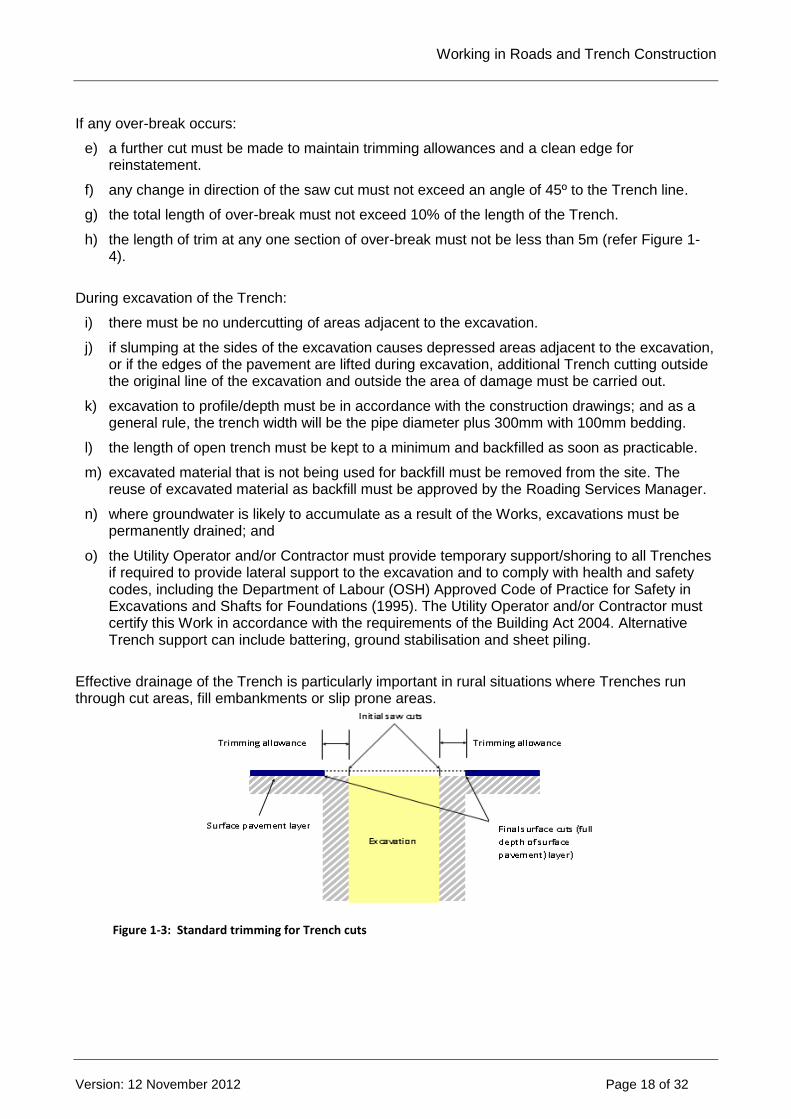
a) any concrete, asphalt or chip seal surfaces must be cut with a power saw in a clean, straight line through the full thickness of the surface layer.
b) the separation distance from the original saw cut (the trimming allowance, refer Figure 1-3) must be a minimum of 150mm, but more may be required to maintain the integrity of the final Trench reinstatement.
c) if necessary, a second saw-cut must be made to ensure that all edges are straight, smooth, parallel to the line of the Trench and that minimum Trench trimming allowance is achieved.
d) all joints must be cut to a depth sufficient to avoid disturbance of adjoining pavement. The depth of cutting must be not less than 30mm, or for concrete carriageways, footpaths and vehicle crossings the depth must be not less than 80% through the concrete pavement layer.
Working in Roads and Trench Construction
--> _ref <-- ### Invalid Field Definition ### --> _format <-- ### Invalid Field Definition ###
Version: 12 November 2012 Page 18 of 32
If any over-break occurs:
e) a further cut must be made to maintain trimming allowances and a clean edge for reinstatement.
f) any change in direction of the saw cut must not exceed an angle of 45º to the Trench line.
g) the total length of over-break must not exceed 10% of the length of the Trench.
h) the length of trim at any one section of over-break must not be less than 5m (refer Figure 1-4).
During excavation of the Trench:
i) there must be no undercutting of areas adjacent to the excavation.
j) if slumping at the sides of the excavation causes depressed areas adjacent to the excavation, or if the edges of the pavement are lifted during excavation, additional Trench cutting outside the original line of the excavation and outside the area of damage must be carried out.
k) excavation to profile/depth must be in accordance with the construction drawings; and as a general rule, the trench width will be the pipe diameter plus 300mm with 100mm bedding.
l) the length of open trench must be kept to a minimum and backfilled as soon as practicable.
m) excavated material that is not being used for backfill must be removed from the site. The reuse of excavated material as backfill must be approved by the Roading Services Manager.
n) where groundwater is likely to accumulate as a result of the Works, excavations must be permanently drained; and
o) the Utility Operator and/or Contractor must provide temporary support/shoring to all Trenches if required to provide lateral support to the excavation and to comply with health and safety codes, including the Department of Labour (OSH) Approved Code of Practice for Safety in Excavations and Shafts for Foundations (1995). The Utility Operator and/or Contractor must certify this Work in accordance with the requirements of the Building Act 2004. Alternative Trench support can include battering, ground stabilisation and sheet piling.
Effective drainage of the Trench is particularly important in rural situations where Trenches run through cut areas, fill embankments or slip prone areas.
Figure 1-3: Standard trimming for Trench cuts

Working in Roads and Trench Construction
--> _ref <-- ### Invalid Field Definition ### --> _format <-- ### Invalid Field Definition ###
Version: 12 November 2012 Page 19 of 32
Figure 1-4: Parallel cutting of joints
After backfill and prior to surface reinstatement, the Contractor must re-cut surfaces if required, to achieve a neat simple pattern for reinstatement and to maintain minimum trimming allowances. Generally this will mean parallel saw cuts on the sides of any area, but for open graded porous asphalt saw cutting is not the recommended method. When a Trench turns a corner, additional allowances must be made, as shown in Figure 1-5.
Figure 1-5: Trench excavation with corners
Figure 1-6 is an example of how an irregular excavation should be expanded to form a more regular shape to minimise disruption to the surface.
Figure 1-6: Finishing of irregular shaped excavations
Trimming allowance
Surface cut to form a neat rectangular or square shape Existing road surface
Working in Roads and Trench Construction
--> _ref <-- ### Invalid Field Definition ### --> _format <-- ### Invalid Field Definition ###
Version: 12 November 2012 Page 20 of 32
8.3 Backfill Materials
All backfill materials:
a) must be in accordance with recognised standards and approved by the Roading Services Manager;
b) must be adequate to ensure that the backfilled area can at least match the pre-Trench subsurface integrity;
c) must be of sufficient quality and strength to support the imposed loading, including Traffic and Road construction loading; and
d) where concrete or other stabilised layers, including geotextile material, exist in the Road pavement, the Contractor must reinstate the Trench with similar material (further guidance on concrete reinstatement is included in Section 9.5).
Thermally-stable backfill:
e) where thermally-stable backfill is required (typically for power cables), the Utility Operator, power cable owner and Corridor Manager must agree on the compaction and standard, prior to CAR application, and put these in the WAP; and
f) when excavations make contact with Trenches of power cables laid in thermally stable backfill, the Contractor must restore the thermally stable backfill to the standards applying before the excavation.
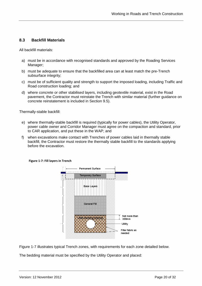
Figure 1-7: Fill layers in Trench
Figure 1-7 illustrates typical Trench zones, with requirements for each zone detailed below. The bedding material must be specified by the Utility Operator and placed:
Working in Roads and Trench Construction
--> _ref <-- ### Invalid Field Definition ### --> _format <-- ### Invalid Field Definition ###
Version: 12 November 2012 Page 21 of 32
g) in a loose state (sand must be dampened) and tamped to achieve compaction and surround of Utility; or
h) in a fluidised state where specifically approved by the Corridor Manager; and
i) to a depth of not less than 100mm or more than 300 mm above the top of the Utility Structure, unless a variance is agreed between the Utility Operator and Corridor Manager.
General fill:
j) in road carriageway, shoulder and footpath, general fill must be well graded granular material free of deleterious material with maximum stone size 75mm;
k) where the Utility Operator and/or Contractor uses suitable excavated material in berms, the required compaction standards must be achieved (refer Section 8.5).
Base layers – Road Carriageways - where there is more than one base layer:
l) the lower base layer (subbase) material must be well-graded crushed granular, with maximum aggregate size 65mm, and a controlled grading curve and weathering and crushing resistance; and
m) the upper base layer (basecourse) for the carriageway being a minimum of 300mm , or the whole basecourse if it is a single layer, must comply with NZTA specification TNZ M/4: Basecourse aggregate, unless the Corridor Manager has approved an alternative basecourse product specification.
Base layers – Footpaths: must be well graded GAP40 granular material. Berms generally do not need a separate base layer other than general fill. Prior to backfilling, excavated material that is unsuitable for backfilling must be removed from site and not be used to backfill Trenches.
8.4 Backfill Placement and Compaction
Placement and compaction of all layers must:
a) be in layers not exceeding 200mm (solid) thickness;
b) allow for appropriate compaction methods around the Utility Structures;
c) have mechanical compaction completed for each subsequent layer in turn; and
d) ensure lapping of any geotextile material in accordance with the manufacturer’s specification.
During backfilling and compaction:
e) care must be taken to ensure no damage occurs to Utility Structures during compaction; and
f) if over break or other disturbance of the pavement layers occurs, the surface of such areas must be re-cut, excavated and backfilled in compliance with this Section.
Where the strata exposed as side walls of a Trench is considered relatively soft such that there may be risk of settlement arising from ongoing post-construction penetration of the granular fill material into the Trench sides, the Utility Operator should discuss backfill options with the Corridor Manager. These may include, for example, the application of a geo-textile liner in the Trench, or the use of modified (lime or cement-treated) granular materials in the vicinity of the soft layer/s.
Working in Roads and Trench Construction
--> _ref <-- ### Invalid Field Definition ### --> _format <-- ### Invalid Field Definition ###
Version: 12 November 2012 Page 22 of 32
Compaction must:
g) be carried out using suitable plant and equipment to achieve the specifications in Section 8.5; and
h) be confirmed by a Clegg hammer, or an agreed alternative, for subbase and deeper fill.
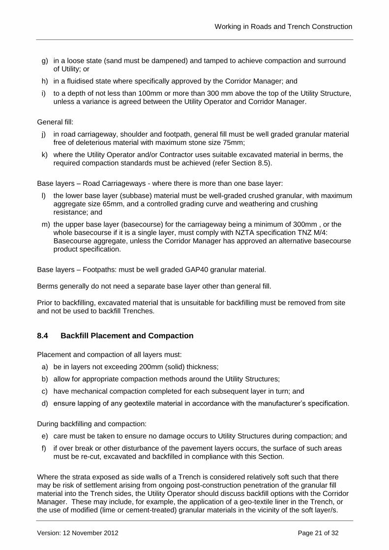
When reinstating excavated concrete layers in the carriageway, the Utility Operator and/or Contractor must ensure that the new concrete:
i) retains at least the performance characteristics of the existing layer.
j) is installed at a minimum depth of 250mm.
k) has a 28-day compressive strength of 20 MPa.
l) is manufactured in accordance with New Zealand Standards NZS 3104: 2003, Specification for concrete production – high grade and special grade or NZS 3109:1997, Concrete construction.
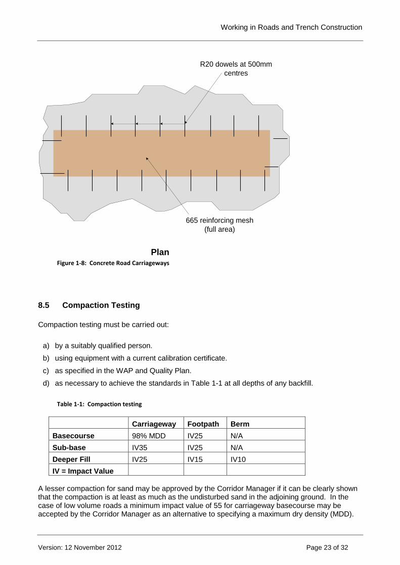
m) interlocks with the old concrete using R20 steel reinforcing bars placed centrally perpendicular to the face at 500mm spacings along all joint faces. The bars must be bonded 250mm into the existing concrete and extend into the new concrete a minimum of 250mm. The concrete must be reinforced with 665 steel mesh placed centrally. Where expansion or contraction joints are affected these must be reinstated.
n) has a coarse broom finished surface and matches the line and crossfall of the Road surface, with allowance for asphalt overlay to be placed to the same thickness as on adjacent pavement as appropriate.
When reinstating concrete in any other areas, the concrete used should be of similar type and finish as the adjacent concrete.
Subgrade
Concrete
Concrete depth as in
adjoining pavement
but not less than 250mm
665 reinforcing mesh
Existing
reinforcing
800mm suggested
minimum width
excavation
500mm R20 dowels
firmly grouted 250mm
into drilled holes
Elevation
Wearing Surface
(eg asphalt)
Working in Roads and Trench Construction
--> _ref <-- ### Invalid Field Definition ### --> _format <-- ### Invalid Field Definition ###
Version: 12 November 2012 Page 23 of 32
R20 dowels at 500mm
centres
665 reinforcing mesh
(full area)
Plan
Figure 1-8: Concrete Road Carriageways
8.5 Compaction Testing
Compaction testing must be carried out:
a) by a suitably qualified person.
b) using equipment with a current calibration certificate.
c) as specified in the WAP and Quality Plan.
d) as necessary to achieve the standards in Table 1-1 at all depths of any backfill.
Table 1-1: Compaction testing
Carriageway Footpath Berm
Basecourse 98% MDD IV25 N/A
Sub-base IV35 IV25 N/A
Deeper Fill IV25 IV15 IV10
IV = Impact Value
A lesser compaction for sand may be approved by the Corridor Manager if it can be clearly shown that the compaction is at least as much as the undisturbed sand in the adjoining ground. In the case of low volume roads a minimum impact value of 55 for carriageway basecourse may be accepted by the Corridor Manager as an alternative to specifying a maximum dry density (MDD).
Working in Roads and Trench Construction
--> _ref <-- ### Invalid Field Definition ### --> _format <-- ### Invalid Field Definition ###
Version: 12 November 2012 Page 24 of 32
A testing regime must be carried out as agreed with the Corridor Manager or, in the absence of any agreement, as outlined below:
e) for trenches in berms, tests at a rate of at least one test per layer of backfill per 15m of Trench, with a minimum of two tests.
f) for trenches in carriageways or under footpaths, tests at a rate of at least one test per layer of backfill per 5m of Trench with a minimum of two tests.
g) where the excavated area is greater than 0.5m2 and less than 5m2, tests at a rate of one test per backfill layer or, for larger excavations, one test per 5m2.
h) all test locations must be uniformly spaced in the pavement.
i) tests must be carried out on every lift of each tested backfill layer to be assured of proper compaction of all of the backfill.
Complying with the above specifications does not remove the responsibility of the Utility Operator and/or Contractor to ensure that no settlement occurs.
Also note that:
Subject to satisfactory test results the above frequency of testing may be reduced with the prior agreement of the Corridor Manager.
The Clegg hammer may be used for testing of general fill and base layers but not for the upper base layer of Carriageways.
Clegg hammer tests only indicate the compaction of the lift last laid of any backfill layer. The impact tester method covers material of 37.5mm and down and may not be suitable for subbase material with larger stone sizes.
The Utility Operator must retain the test records and make them available to the Corridor Manager on request and failure to do so may require the warranty period to be extended to 4 years.
9. SURFACE LAYER REINSTATEMENT
9.1 General Requirements
The Utility Operator and/or Contractor must:
a) use suitably qualified and experienced persons for the construction of Road surfacing; and
b) comply with the National Code and relevant industry standards.
The Contractor must, unless otherwise agreed with the Corridor Manager:
c) not open Trenched sites to Traffic until temporary or permanent resurfacing is in place.
d) not use temporary resurfacing unless permanent resurfacing is not practicable.
e) have permanent resurfacing in place within seven days of completion of backfill or temporary surfacing.
The Contractor must ensure the reinstated surfacing:
f) is installed in clean, long, straight lines parallel to the kerb or footpath, or for transverse Trenches, perpendicular to the kerb and channel.
Working in Roads and Trench Construction
--> _ref <-- ### Invalid Field Definition ### --> _format <-- ### Invalid Field Definition ###
Version: 12 November 2012 Page 25 of 32
g) uses materials that match the surrounding surface in type, quality, texture, skid resistance and strength.
h) matches at least the pre-existing surface in smoothness or ride quality for vehicles (vertical movements).
i) has a finished surface level and adjoining surface shaped to avoid ponding of surface water, such that the deviation of the surface from a 3m straight edge does not exceed 5mm.
j) does not vary more than 5mm in any location from the original surface.
k) is continuously graded towards stormwater drainage channels or gully entries.
l) has no lips greater than 3mm high in pedestrian surfaces.
If the Corridor Manager requires a Road surface level survey prior to Work commencing, the Utility Operator must at its own cost carry out a survey that:
m) measures the surface level at 5m intervals on each kerb and immediately around the proposed excavation.
n) is accurate and has sufficient offset marks for levels to be re-established at the same points at any stage of the Work.
At the Corridor Manager’s request, the Utility Operator must carry out Road surface roughness testing on a before and after basis for large projects.
9.2 Reinstatement near a Joint or Edge
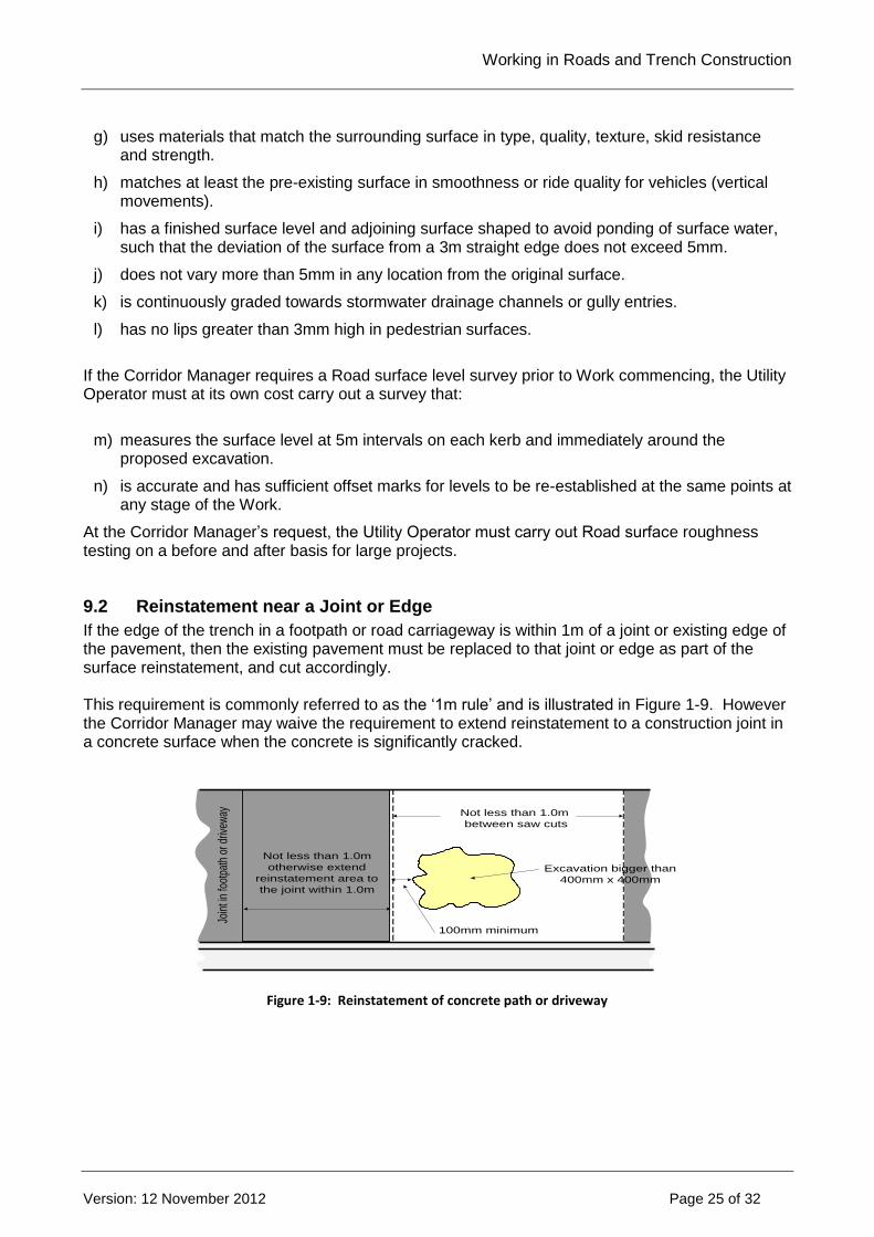
If the edge of the trench in a footpath or road carriageway is within 1m of a joint or existing edge of the pavement, then the existing pavement must be replaced to that joint or edge as part of the surface reinstatement, and cut accordingly. This requirement is commonly referred to as the ‘1m rule’ and is illustrated in Figure 1-9. However the Corridor Manager may waive the requirement to extend reinstatement to a construction joint in a concrete surface when the concrete is significantly cracked.
100mm minimum
Not less than 1.0m
otherwise extend
reinstatement area to
the joint within 1.0m
Excavation bigger than
400mm x 400mm
Not less than 1.0m
between saw cuts
Join
t in
foot
path
or d
rivew
ay
Figure 1-9: Reinstatement of concrete path or driveway
Working in Roads and Trench Construction
--> _ref <-- ### Invalid Field Definition ### --> _format <-- ### Invalid Field Definition ###
Version: 12 November 2012 Page 26 of 32
9.3 Trench Reinstatement in Driveways
Where possible all entranceways are to be direct drilled or thrust under. If that is unable to be carried out then the following applies: 9.3.1 Heavy Duty Vehicle Crossing Heavy duty vehicle crossings are continuously reinforced. After disturbance of concrete crossings by surface openings, the area reinstated shall satisfy either of the following:
If the crossing depth kerb face to boundary is less than 3.0 metre and the crossing width less than 3.5 metre then the entire crossing shall be removed and replaced, including the kerb.
For larger crossings, no more than one saw cut may be made in the crossing either parallel with the road or perpendicular as applicable. The part of the crossing between the new saw cut and the nearest edge of the crossing shall be replaced. For this option steel dowels shall be drilled into the cut edge of the old crossing to ensure adequate shear capacity. On completion of the reinstatement the crossing shall have no more than one joint between the edges of the crossing and the joint shall be no closer than 1.5 metre from any edge of the crossing.
If these conditions cannot be complied with then the entire crossing shall be replaced. 9.3.2 Residential Vehicle Crossing Trenches parallel with kerb/path/berm line
If the crossing depth is 3 metre or less then the entire crossing shall be replaced.
If the crossing depth is greater than 3 metres then a partial reinstatement may be undertaken provided all of the following conditions are satisfied. The reinstatement surface shall not be less than 200mm wider each side than the trench width nor less than a total of 1.0 metre in total width. On completion of the reinstatement the crossing shall have no more than one joint between edges of the crossing and the joint shall be no closer than 1.0 metre from any edge of the crossing.
Trenches transverse to the kerb/path/berm line
Trench resurfacing shall be at least 200mm wider each side than the trench width and on completion of the reinstatement the crossing shall have no more than one joint between edges of the crossing and the joint shall be no closer than 1 metre from any edge of the crossing. If this cannot be complied with then the full crossing is to be replaced.
9.4 Temporary Surface Reinstatement
Temporary surfaces constructed by the Contractor must be:
a) ’cold mix‘ asphalt or an equivalent approved by the Corridor Manager.
b) at a surface level between 5mm below and 15mm above the original surface level, with a lip not greater than 5mm in any part of the surface.
c) laid in a manner and to a depth that is durable for both vehicular and pedestrian use.
d) maintained by the Utility Operator and/or Contractor until permanent surfacing has been undertaken, including undertaking any repairs as soon as possible if damaged.
e) fully removed prior to reinstatement with permanent materials.
Working in Roads and Trench Construction
--> _ref <-- ### Invalid Field Definition ### --> _format <-- ### Invalid Field Definition ###
Version: 12 November 2012 Page 27 of 32
Where the Utility Operator and/or Contractor considers that special circumstances (but not at pedestrian crossings) require leaving an area of road carriageway and footpath without a proper temporary surface, the Utility Operator and/or Contractor must:
f) seek prior agreement from the Corridor Manager.
g) provide additional ‘Uneven Surface’ and ‘Speed Restriction’ signage.
h) maintain the surface within agreed tolerances of the surrounding surface level.
i) reinstate the surface with a proper temporary surface within one Working Day or as agreed with the Corridor Manager.
Where steel plates are used, they must:
j) be in place for no more than seven days or as agreed with the Corridor Manager.
k) have their use approved by the Corridor Manager.
l) be securely fixed in place to prevent dislodgement and to not be a nuisance or danger to passing traffic (vehicles, pedestrians, cyclists), users of local properties.
m) be skid resistant, secured and cushioned to prevent them from rocking, moving or creating noise.
n) be of sufficient strength and quality to support imposed Traffic loading.
o) have appropriate signposting with temporary speed restrictions and hazard warnings (refer CoPTTM; for Local Roads, see the Local Roads Supplement).
p) have a ramp formed and filleted to ensure safe pedestrian and vehicular access.
q) have any temporary markings required by the Corridor Manager.
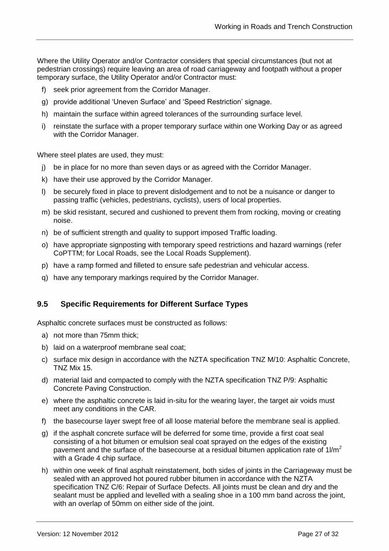
9.5 Specific Requirements for Different Surface Types
Asphaltic concrete surfaces must be constructed as follows:
a) not more than 75mm thick;
b) laid on a waterproof membrane seal coat;
c) surface mix design in accordance with the NZTA specification TNZ M/10: Asphaltic Concrete, TNZ Mix 15.
d) material laid and compacted to comply with the NZTA specification TNZ P/9: Asphaltic Concrete Paving Construction.
e) where the asphaltic concrete is laid in-situ for the wearing layer, the target air voids must meet any conditions in the CAR.
f) the basecourse layer swept free of all loose material before the membrane seal is applied.
g) if the asphalt concrete surface will be deferred for some time, provide a first coat seal consisting of a hot bitumen or emulsion seal coat sprayed on the edges of the existing pavement and the surface of the basecourse at a residual bitumen application rate of 1l/m2 with a Grade 4 chip surface.
h) within one week of final asphalt reinstatement, both sides of joints in the Carriageway must be sealed with an approved hot poured rubber bitumen in accordance with the NZTA specification TNZ C/6: Repair of Surface Defects. All joints must be clean and dry and the sealant must be applied and levelled with a sealing shoe in a 100 mm band across the joint, with an overlap of 50mm on either side of the joint.

Working in Roads and Trench Construction
--> _ref <-- ### Invalid Field Definition ### --> _format <-- ### Invalid Field Definition ###
Version: 12 November 2012 Page 28 of 32
Note that the limited thickness of asphalt and limited width usually makes use of instrument confirmation impractical. Paver-laid asphaltic concrete is recommended to achieve the density and surface level tolerances of this Code. Extra care should be taken with hand-placed asphaltic concrete. Open graded porous asphaltic surface must comply with the following requirements:
i) surface mix design, paver laying and compacting must be undertaken in accordance with the NZTA specification TNZ P/11: Open Graded Porous Asphalt.
j) the base of all areas to be covered by the porous asphaltic concrete must be chip sealed evenly with a bitumen emulsion complying with the NZTA specification TNZ M/1: Roading Bitumen's.
k) the surface must be laid on self-draining waterproof surfaces.
l) joint sealing must be undertaken as per Sections 5.6.4.1(g) and (h) above.
Structural asphalt concrete surfaces must:
m) be specifically designed and constructed to restore the structural integrity of the original pavement.
n) have reinstatement details approved by the Corridor Manager.
Chip seal Carriageways must:
o) be reinstated using a two coat chip seal. The first coat must be a coarse grade chip (e.g. Grade 3) and the second coat a finer grade (e.g. Grade 4 or 5) to visually blend with the existing adjacent surfacing. The second coat must overlap the existing surface by not less than 100mm;
p) where the area being reinstated is adjacent to a concrete channel, the new seal must overlap the channel by a minimum of 50mm; and
q) be laid in accordance with the NZTA specification TNZ P/3: First Coat Sealing and the Chip sealing in New Zealand Handbook.
Texturised asphalt reinstatement must:
r) be laid in accordance with the NZTA specifications TNZ P/4: Resealing or TNZ P/17: Performance Based Specification for Bituminous Reseals; and
s) within one year of the initial reinstatement, the area must be texturised with a single or two coat chip seal, with chip size selected to visually blend with the existing adjacent surface. The seal coat must overlap the existing surface by not less than 100mm.
Instead of the Contractor carrying out the Work, the Corridor Manager and Utility Operator and/or Contractor may agree an equivalent fee to transfer the responsibility for texturising to the Corridor Manager. Segmental block paved surfaces must:
t) be reinstated in the same materials and to a standard at least equivalent to the original surface in accordance with NZS 3116.
u) be laid in accordance with the requirements of the manufacturer and the Corridor Manager.
v) have any chipped or damaged blocks replaced with the same type.

Working in Roads and Trench Construction
--> _ref <-- ### Invalid Field Definition ### --> _format <-- ### Invalid Field Definition ###
Version: 12 November 2012 Page 29 of 32
w) where reinstating around surface features in coloured concrete to match blocks, the concrete must not extend more than one block length from the base of the pole or feature.
To re-establish a tight interlocking pattern with specified joint widths, it may be necessary to remove adjoining blocks and relay them up to a bordering physical feature such as the Road kerb.
9.6 Special Paving, Amenity Areas and Decorative Areas
Special Paving Areas must:
a) be reinstated by a specialist Contractor.
b) match the original standard, with the same quality, texture, type, colour and material of the existing pavement and minimal visible evidence of the Trench reinstatement.
c) have the whole panel replaced, where the paving is laid out in panels.
d) match any special treatments used in the existing construction (e.g. geogrid membranes, chip seal, high friction surface, grooved asphaltic concrete).
e) use alternatives agreed with the Corridor Manager, where matching materials are not available.
Some treatments such as geogrids need extended excavation to properly anchor the product. Amenity and special decorative areas must:
f) be reinstated by a Contractor approved by the Corridor Manager.
g) match the original standard, with the same quality, texture, type, colour and material as the existing pavement with minimal visible evidence of the Trench reinstatement.
h) have any urban design features, architectural finishes, gardens, artworks and landscaping properly reinstated to the pre-existing condition.
9.7 Road Markings, Signs and Furniture
The Utility Operator and/or Contractor must ensure that road markings are:
a) recorded prior to being impacted by Works, including description of markings by type, their location and any special items;
b) located by way of an offset at the side of the Road to enable accurate remarking; and
c) reinstated prior to completion of Works and, in urban areas, preferably prior to reopening the lane or road to Traffic.
The Utility Operator and/or Contractor should take photographic evidence of pre-existing markings where significant impacts on markings are expected. The Corridor Manager may hold records of existing road markings and, if so, should make this available as required. The Utility Operator and/or Contractor must ensure that temporary road markings, where required for Traffic safety purposes, are:
d) of an approved type and suitable for the purpose as specified by the Corridor Manager;

Working in Roads and Trench Construction
--> _ref <-- ### Invalid Field Definition ### --> _format <-- ### Invalid Field Definition ###
Version: 12 November 2012 Page 30 of 32
e) in place prior to Traffic usage of the Road surface areas affected;
f) in an effective condition for the period of use until the permanent situation is established;
g) fully removed prior to re-opening the area.
The Utility Operator and/or Contractor must ensure that signs, furniture and lids:
h) are protected and maintained during the Work;
i) are replaced if they become damaged or lost prior to completion of the Work; and
j) have utility chamber lids and covers restored to the finished road level.
The Corridor Manager may carry out reinstatement of signs and markings on behalf of the Utility Operator at the Utility Operator’s cost, if not reinstated within a reasonable timeframe. The specification, location and marking of fire hydrants must be in accordance with SNZ PAS 4509, Appendix L.
The Utility Operator and/or Contractor must ensure that:
k) fire hydrant box lids are not covered over during Works;
l) fire hydrant box lids remain identifiable during Works;
m) full markings indicating the location of fire hydrants are visible before the Contractor leaves the site.
n) water meter reading markings on the roads edge are reinstated if damaged or 'lost".
Temporary markings include:
o) the yellow fire hydrant box lid;
p) an indicator plate or marker post at the edge of the road or footpath.
Some markings may not be affected, such as painted hydrant covers, which would serve as temporary markers until full markings were reinstated.
9.8 Trench Excavation in Grassed Areas
9.8.1 General
Repairs shall generally involve:
a) Removal of excess material and cart from the site (maintain or improve drainage shaping).
b) Backfilling and compacting with excavated material.
c) Reinstate disturbed surfaces with approved topsoil and sow as described below.
d) All stones or debris shall be removed from the topsoil prior to sowing.
e) Regular maintenance shall be undertaken until the grass is 100% established.
The repair work is to be executed with particular care to ensure that:
f) The finished surface is flush with adjacent surfaces.
g) There is no subsidence over a period of 24 months.
Working in Roads and Trench Construction
--> _ref <-- ### Invalid Field Definition ### --> _format <-- ### Invalid Field Definition ###
Version: 12 November 2012 Page 31 of 32
h) In all cases the Contractor must continue to maintain water, re-seed, re-topsoil or fertilise the berm until a dense grass strike has been achieved. Stones, basecourse and other debris must be removed from the berm surface before Practical Completion.
i) On confirmation that a dense grass strike has been achieved, the berm works will be practically completed.
9.8.2 Compaction
All backfill material (excluding the 100mm depth of topsoil) shall be compacted using mechanically operated compaction equipment. Compaction shall be carried out in layers not exceeding 300mm in loose depth and the resulting density must not be less than 90% of the in-situ compacted density as determined by NZS 4402: 1986 Section 4.1.1.
9.8.3 Grass Seed
Upon attaining the final surface levels, the minimum 100mm topsoil shall be rolled and sown with an approved grass seed mixture containing no noxious weed and shall be evenly spread at a rate of 20 grams per square metre (20gm/m²). Unless otherwise directed in writing, a suitable seed mixture for grassing all disturbed grass areas shall be:
85% amenity turf ryegrass
15% red fescue Prior to sowing, the surface shall be broken up and raked to a fine tilth. The seed shall be evenly spread and thoroughly raked in, followed by a light rolling or tamping of the surface.
10. BONDS
If a contractor is issued three or more non-conformance notices within a 6 month period then that contractor shall be required to enter into a bond with Council for any future works or for the works that are non-complying. The security shall be satisfied by either the execution of a bond by a surety acceptable to Council or by payment to Council of cash in the amount of the bond. The release of the bond shall be initiated by either the contractor completing a period of 6 months without the need for any further non-compliance notices being issued, or by completing the bonded works to Council’s satisfaction, whichever is longer. The amount of the bond shall be set by the Council upon receipt of:
Two quotes for identical work from independent contractors on their company letterhead
A copy of the engineering conditions from any relevant subdivision or land use consent
Copy of the engineering plans detailing the location and dimensions of, and quantity of materials required for, the bonded works
The date by which the work will be completed. The amount of the bond shall be 50% greater than the estimate of the cost of the work.
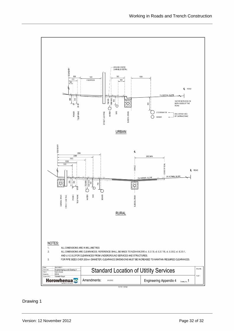
Working in Roads and Trench Construction
--> _ref <-- ### Invalid Field Definition ### --> _format <-- ### Invalid Field Definition ###
Version: 12 November 2012 Page 32 of 32
Drawing 1