jis c 1211-2 - zb.guaihou.comzb.guaihou.com/stdpool/jis c1211-2-2009-en.pdf · jis c 60068-2-27...
TRANSCRIPT

JIS C 1211-2 :2009
JAPANESE INDUSTRIAL STANDARD
Translated and Published by
Japanese Standards Association
Alternating-current watt-hour meters (for direct connection) - Part 2: Measuring instruments used in transaction or certification
ICS 17.220.20
Reference number: JIS C 1211-2 : 2009 (E)
PROTECTED BY COPYRIGHT 26 S

C 1211-2 : 2009
Date of Establishment: 2009-04-20
Date of Public Notice in Official Gazette: 2009-04-20
Investigated by: Japanese Industrial Standards Committee
Standards Board
Technical Committee on Testing and Measurement Technology
© JSA 2010
JIS C 1211-2:2009, First English edition published in 2010-06
Translated and published by: Japanese Standards Association 4-1-24, Akasaka, Minato-ku, Tokyo, 107-8440 JAPAN
In the event of any doubts arising as to the contents, the original JIS is to be the final authority.
All rights reserved. Unless otherwise specified, no part of this publication may be reproduced or utilized in any form or by any means, electronic or mechanical, including photocopying and microfilm, without permission in writing from the publisher.
Printed in Japan KKiAT
PROTECTED BY COPYRIGHT
C 1211-2 : 2009
Contents
Page
Introduction·········································· ...................................................... ·························1
1 Scope················································· ...................................................... ·····················1
2 Normative references ...................................................... ··········································1
3 Terms and definitions ............................................................................................... 1
4 Classification .............................................................................................................. 4
5 Marking ..................................................................................................... ··················5 5.1 Meter ............................................................................................................ ···············5
5.2 Separable indication mechanism .. ···········································································6
6 Performance ............................................................................................................... 6
6.1 Verification tolerance ...................................................... ··········································6 6.2 Electrical performance .............................................................................................. 6
6.3 Mechanical performance ...................................................... ···································13
6.4 Temperature rise of current coil and terminal···················································17 6.5 Insulation performance···························································································17 6.6 Weather resistance ...................................................... ············································17 6.7 Material ............................................................................................................ ········20
7 Test methods ............................................................................................................ 20
7.1 Instrumental error test ...................................................... ····································20 7.2 Test of electrical performance ...................................................... ·························21 7.3 Test of mechanical performance ...................................................... ······················31
7.4 Temperature rise test of current coil and terminal··········································· 35 7.5 Test of insulation performance ...................................................... ························36 7.6 Weather resistance test ...................................................... ····································37 7.7 Test of material ...................................................... ·················································43
8 Verification··············································································································· 43
9 Inspection during use ...................................................... ·······································43
10 Correspondence relation ...................................................... ···································44
Annex A (normative) Method of verification ...................................................... ········45
Annex B (normative) Inspection during use ...................................................... ········46
(i)
PROTECTED BY COPYRIGHT
C 1211-2 : 2009
Foreword
This translation has been made based on the original Japanese Industrial Standard established by the Minister of Economy, Trade and Industry through deliberations at the Japanese Industrial Standards Committee in accordance with the Industrial Standardization Law.
Consequently JIS C 1211: 1995 was withdrawn and partially replaced with this Standard.
This JIS document is protected by the Copyright Law.
Attention is drawn to the possibility that some parts of this Standard may conflict with a patent right, application for a patent after opening to the public, utility model right or application for registration of utility model after opening to the public which have technical properties. The relevant Minister and the Japanese Industrial Standards Committee are not responsible for identifying the patent right, application for a patent after opening to the public, utility model right or application for registration of utility model after opening to the public which have the said technical properties.
JIS C 1211 consists of the following 2 parts under the general title "Alternatingcurrent watt-hour meters (for direct connection}":
Part 1: General measuring instrument
Part 2: Measuring instruments used in transaction or certification
Cii)
PROTECTED BY COPYRIGHT
JAPANESE INDUSTRIAL STANDARD JIS C 1211-2 : 2009
Alternating-current watt-hour meters (for direct connection)-Part 2: Measuring instruments used in
transaction or certification
In troduction
This Japanese Industrial Standard is established for the purpose of specifying the technical standards and test methods concerning structure and performance requirements of the alternating-current watt-hour meters (for direct connection), among other requirements stipulated for the specified measuring instruments given in Measurement Act. The conformance of the watt-hour meter with this Standard, by itself, is not to certify that the meter has passed the verification test stipulated in Measurement Act. Furthermore, the watt-hour meters (for direct connection) cannot be given the marking stipulated in Article 19 of the Industrial Standardization Law, which indicates their conformity with this Standard.
1 Scope
This Standard specifies the induction type and the electronic normal watt-hour meters which are used for measurement in transaction or certification in Japan, and used independently without combining with an instrument transformer, in single-phase two-wire system, single-phase three-wire system, three-phase three-wire system and three-phase four-wire system circuits (hereafter referred to as "meters").
Other requirements than specified in this Standard shall be in accordance with JIS C 1210.
2 Norma ti ve references
The following standards contain provisions which, through reference in this text, constitute provisions of this Standard. The most recent editions of the standards (including amendments) indicated below shall be applied.
JIS C 1210 General rules for electricity meters
JIS C 60068-2-6 Environmental testing Part 2: Tests-Test Fc: Vibration (sinusoidal)
JIS C 60068-2-27 Basic environmental testing procedures Part 2: Tests, Test Ea and guidance: Shock
JIS K 2246 Rust preventive oils
JIS Z 2371 Methods of salt spray testing
3 Terms and definitions
For the purposes of this Standard, the terms and definitions given in JIS C 1210 and the following definitions apply.
PROTECTED BY COPYRIGHT
2 C 1211-2 : 2009
3.1 indication mechanism
a set of scale marks which indicate a measurement value continuously or intermittently at regular intervals
3.2 separable indication mechanism
an indication mechanism which is separated from the main body of a meter by a cord, etc., or externally connected to it by a connector, etc.
3.3 instrumental error
the rate of the value obtained by subtracting a true value from a measurement value to the true value
NOTE: In JIS C 1211-1, it is referred to as "error."
3.4 instrumental error test
a test to judge, by measuring the instrumental error of a meter, whether the meter conforms to the technical standards concerning structure stipulated in Measurement Act
3.5 verification
an inspection of specified measuring instruments stipulated in Measurement Act
NOTE: It is stipulated in the Measurement Act that the verifications are to be performed, depending on the classification of the specified measuring instrument, by the prefectural governor, a designated verification body, National Institute of Advanced Industrial Science and Technology, and Japan Electric Meters Inspection Corporation.
3.6 inspection during use
an inspection of performance, etc. of meters being used in the market, conducted after the manufacture of electric meters and instrument transformers
3.7 verification tolerance
tolerance expressed by the absolute value of an instrumental error in verification
3.8 user's tolerance
tolerance expressed by the absolute value of an instrumental error in inspection during use
3.9 type approval marking
marking which indicates that the meter belongs to a certified type of specified measuring instruments stipulated in the Measurement Act
3.10 electronic meter
a meter which measures and operates by using electronic parts such as semiconductors
3.11 induction type meter
a meter which operates by electric currents induced in an induction movable element (generally a disk) due to electric currents passing in a fixed coil
PROTECTED BY COPYRIGHT
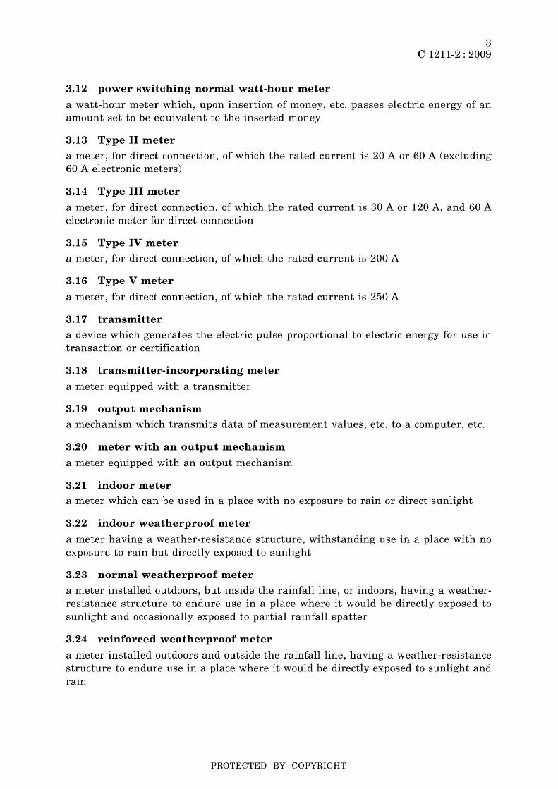
3.12 power switching normal watt-hour meter
3 C 1211-2 : 2009
a watt-hour meter which, upon insertion of money, etc. passes electric energy of an amount set to be equivalent to the inserted money
3.13 Type II meter
a meter, for direct connection, of which the rated current is 20 A or 60 A (excluding 60 A electronic meters)
3.14 Type III meter
a meter, for direct connection, of which the rated current is 30 A or 120 A, and 60 A electronic meter for direct connection
3.15 Type IV meter
a meter, for direct connection, of which the rated current is 200 A
3.16 Type V meter
a meter, for direct connection, of which the rated current is 250 A
3.1 7 transmitter
a device which generates the electric pulse proportional to electric energy for use in transaction or certification
3.18 transmitter-incorporating meter
a meter equipped with a transmitter
3.19 ou tpu t mechanism
a mechanism which transmits data of measurement values, etc. to a computer, etc.
3.20 meter with an output mechanism
a meter equipped with an output mechanism
3.21 indoor meter
a meter which can be used in a place with no exposure to rain or direct sunlight
3.22 indoor weatherproof meter
a meter having a weather-resistance structure, withstanding use in a place with no exposure to rain but directly exposed to sunlight
3.23 normal weatherproof meter
a meter installed outdoors, but inside the rainfall line, or indoors, having a weatherresistance structure to endure use in a place where it would be directly exposed to sunlight and occasionally exposed to partial rainfall spatter
3.24 reinforced weatherproof meter
a meter installed outdoors and outside the rainfall line, having a weather-resistance structure to endure use in a place where it would be directly exposed to sunlight and raIn
PROTECTED BY COPYRIGHT
4 C 1211-2 : 2009
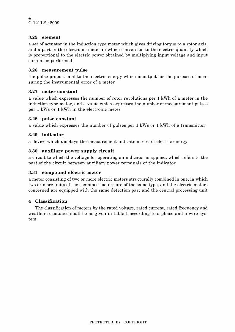
3.25 element
a set of actuator in the induction type meter which gives driving torque to a rotor axis, and a part in the electronic meter in which conversion to the electric quantity which is proportional to the electric power obtained by multiplying input voltage and input current is performed
3.26 measurement pulse
the pulse proportional to the electric energy which is output for the purpose of measuring the instrumental error of a meter
3.27 meter constant
a value which expresses the number of rotor revolutions per 1 kWh of a meter in the induction type meter, and a value which expresses the number of measurement pulses per 1 k W s or 1 kWh in the electronic meter
3.28 pulse constant
a value which expresses the number of pulses per 1 kWs or 1 kWh of a transmitter
3.29 indicator
a device which displays the measurement indication, etc. of electric energy
3.30 auxiliary power supply circuit
a circuit to which the voltage for operating an indicator is applied, which refers to the part of the circuit between auxiliary power terminals of the indicator
3.31 compound electric meter
a meter consisting of two or more electric meters structurally combined in one, in which two or more units of the combined meters are of the same type, and the electric meters concerned are equipped with the same detection part and the central processing unit
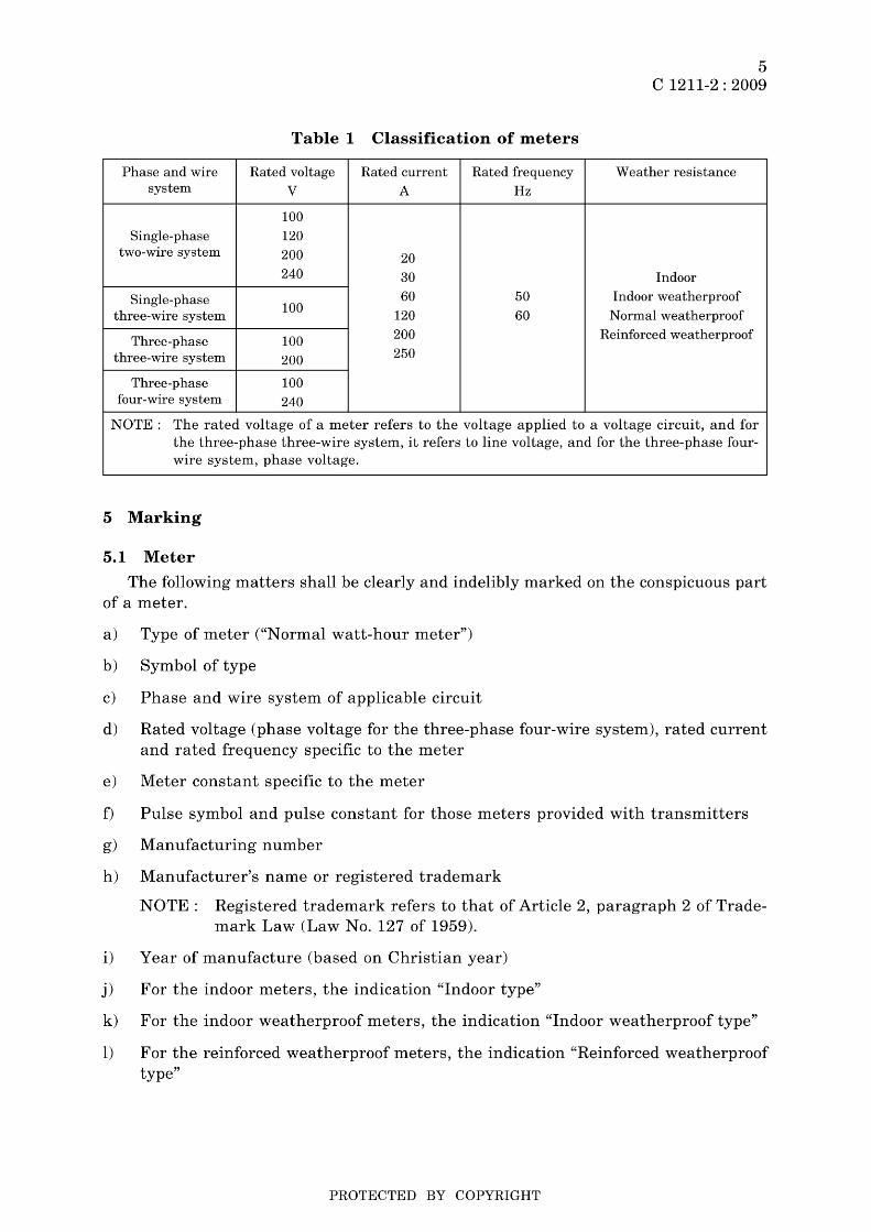
4 Classification
The classification of meters by the rated voltage, rated current, rated frequency and weather resistance shall be as given in table 1 according to a phase and a wire system.
PROTECTED BY COPYRIGHT
Phase and wire system
Single-phase two-wire system
Single-phase three-wire system
Three-phase three-wire system
Three-phase four-wire system
Table 1 Classification of meters
Rated voltage Rated current Rated frequency
V A Hz
100 120 200 20 240 30
60 50 100 120 60
100 200
200 250
100 240
5 C 1211-2 : 2009
Weather resistance
Indoor Indoor weatherproof
Normal weatherproof Reinforced weatherproof
NOTE: The rated voltage of a meter refers to the voltage applied to a voltage circuit, and for the three-phase three-wire system, it refers to line voltage, and for the three-phase four-wire system, phase voltage.
5 Marking
5.1 Meter
The following matters shall be clearly and indelibly marked on the conspicuous part of a meter.
a) Type of meter ("Normal watt-hour meter")
b) Symbol of type
c) Phase and wire system of applicable circuit
d) Rated voltage (phase voltage for the three-phase four-wire system), rated current and rated frequency specific to the meter
e) Meter constant specific to the meter
f) Pulse symbol and pulse constant for those meters provided with transmitters
g) Manufacturing number
h) Manufacturer's name or registered trademark
NOTE: Registered trademark refers to that of Article 2, paragraph 2 of Trade-mark Law (Law No. 127 of 1959).
i) Year of manufacture (based on Christian year)
j) For the indoor meters, the indication "Indoor type"
k) For the indoor weatherproof meters, the indication "Indoor weatherproof type"
1) For the reinforced weatherproof meters, the indication "Reinforced weatherproof type"
PROTECTED BY COPYRIGHT
6 C 1211-2 : 2009
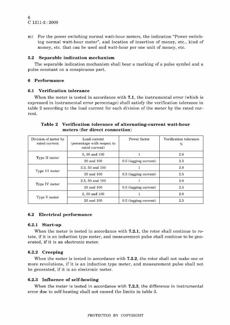
m) For the power switching normal watt-hour meters, the indication "Power switching normal watt-hour meter", and location of insertion of money, etc., kind of money, etc. that can be used and watt-hour per one unit of money, etc.
5.2 Separable indication mechanism
The separable indication mechanism shall bear a marking of a pulse symbol and a pulse constant on a conspicuous part.
6 Performance
6.1 Verification tolerance
When the meter is tested in accordance with 7.1, the instrumental error (which is expressed in instrumental error percentage) shall satisfy the verification tolerance in table 2 according to the load current for each division of the meter by the rated current.
Table 2 Verification tolerance of alternating-current watt-hour meters (for direct connection)
Division of meter by Load current Power factor Verification tolerance rated current (percentage with respect to %
rated current)
5,50 and 100 1 2.0 Type II meter
20 and 100 0.5 (lagging current) 2.5
3.3, 50 and 100 1 2.0 Type III meter
20 and 100 0.5 (lagging current) 2.5
2.5, 50 and 100 1 2.0 Type IV meter
20 and 100 0.5 (lagging current) 2.5
2,50 and 100 1 2.0 Type V meter
20 and 100 0.5 (lagging current) 2.5
6.2 Electrical performance
6.2.1 Start-up
When the meter is tested in accordance with 7.2.1, the rotor shall continue to rotate, if it is an induction type meter, and measurement pulse shall continue to be generated, if it is an electronic meter.
6.2.2 Creeping
When the meter is tested in accordance with 7.2.2, the rotor shall not make one or more revolutions, if it is an induction type meter, and measurement pulse shall not be generated, if it is an electronic meter.
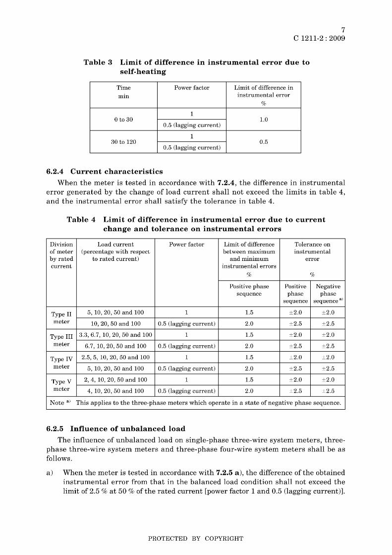
6.2.3 Influence of self-heating
When the meter is tested in accordance with 7.2.3, the difference in instrumental error due to self-heating shall not exceed the limits in table 3.
PROTECTED BY COPYRIGHT
7 C 1211-2 : 2009
Table 3 Limit of difference in instrumental error due to self-heating
Time Power factor Limit of difference in
min instrumental error
%
1 o to 30 1.0
0.5 (lagging current)
1 30 to 120 0.5
0.5 (lagging current)
6.2.4 Current characteristics
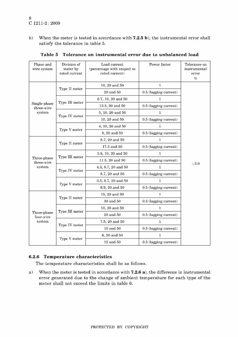
When the meter is tested in accordance with 7.2.4, the difference in instrumental error generated by the change of load current shall not exceed the limits in table 4, and the instrumental error shall satisfy the tolerance in table 4.
Table 4 Limit of difference in instrumental error due to current change and tolerance on instrumental errors
Division Load current Power factor Limit of difference Tolerance on of meter (percentage with respect between maximum instrumental by rated to rated current) and minimum error current instrumental errors
% %
Positive phase Positive Negative sequence phase phase
sequence sequence a)
Type II 5, 10, 20, 50 and 100 1 1.5 ±2.0 ±2.0
meter 10,20,50 and 100 0.5 (lagging current) 2.0 ±2.5 ±2.5
Type III 3.3,6.7, 10,20,50 and 100 1 1.5 ±2.0 ±2.0
meter 6.7, 10,20,50 and 100 0.5 (lagging current) 2.0 ±2.5 ±2.5
Type IV 2.5, 5, 10,20, 50 and 100 1 1.5 ±2.0 ±2.0
meter 5, 10, 20, 50 and 100 0.5 (lagging current) 2.0 ±2.5 ±2.5
Type V 2,4, 10, 20, 50 and 100 1 1.5 ±2.0 ±2.0
meter 4, 10, 20, 50 and 100 0.5 (lagging current) 2.0 ±2.5 ±2.5
Note a) This applies to the three-phase meters which operate in a state of negative phase sequence.
6.2.5 Influence of unbalanced load
The influence of unbalanced load on single-phase three-wire system meters, threephase three-wire system meters and three-phase four-wire system meters shall be as follows.
a) When the meter is tested in accordance with 7.2.5 a), the difference of the obtained instrumental error from that in the balanced load condition shall not exceed the limit of 2.5 % at 50 % of the rated current [power factor 1 and 0.5 (lagging current)].
PROTECTED BY COPYRIGHT
8 C 1211-2 : 2009
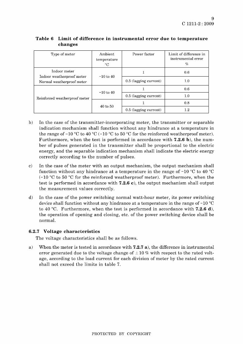
b) When the meter is tested in accordance with 7.2.5 b), the instrumental error shall satisfy the tolerance in table 5.
Table 5 Tolerance on instrumental error due to unbalanced load
Phase and Division of Load current Power factor Tolerance on wire system meter by (percentage with respect to instrumental
rated current rated current) error
%
10,20 and 50 1 Type II meter
20 and 50 0.5 (lagging current)
6.7, 10,20 and 50 1 Single-phase Type III meter
three-wire 13.3, 20 and 50 0.5 (lagging current)
system 5, 10, 20 and 50 1 Type IV meter
10,20 and 50 0.5 (lagging current)
4, 10, 20 and 50 1 Type V meter
8,20 and 50 0.5 (lagging current)
8.7,20 and 50 1 Type II meter
17.3 and 50 0.5 (lagging current)
5.8, 10, 20 and 50 1 Three-phase Type III meter
three-wire 11.5, 20 and 50 0.5 (lagging current)
±3.0 system 4.3, 8.7, 20 and 50 1
Type IV meter 8.7,20 and 50 0.5 (lagging current)
3.5,8.7, 20 and 50 1 Type V meter
6.9, 20 and 50 0.5 (lagging current)
15,20 and 50 1 Type II meter
30 and 50 0.5 (lagging current)
10,20 and 50 1 Three-phase Type III meter
four-wire 20 and 50 0.5 (lagging current)
system 7.5, 20 and 50 1 Type IV meter
15 and 50 0.5 (lagging current)
6,20 and 50 1 Type V meter
12 and 50 0.5 (lagging current)
6.2.6 Temperature characteristics
The temperature characteristics shall be as follows.
a) When the meter is tested in accordance with 7.2.6 a), the difference in instrumental error generated due to the change of ambient temperature for each type of the meter shall not exceed the limits in table 6.
PROTECTED BY COPYRIGHT
9 C 1211-2 : 2009
Table 6 Limit of difference in instrumental error due to temperature changes
Type of meter Ambient Power factor Limit of difference in
temperature instrumental error
°C %
Indoor meter 1 0.6 Indoor weatherproof meter -10 to 40
Normal weatherproof meter 0.5 (lagging current) 1.0
1 0.6 -10 to 40
Reinforced weatherproof meter 0.5 (lagging current) 1.0
1 0.8 40 to 50
0.5 (lagging current) 1.2
b) In the case of the transmitter-incorporating meter, the transmitter or separable indication mechanism shall function without any hindrance at a temperature in the range of -10°C to 40°C (-10°C to 50°C for the reinforced weatherproof meter). Furthermore, when the test is performed in accordance with 7.2.6 b), the number of pulses generated in the transmitter shall be proportional to the electric energy, and the separable indication mechanism shall indicate the electric energy correctly according to the number of pulses.
c) In the case of the meter with an output mechanism, the output mechanism shall function without any hindrance at a temperature in the range of -10°C to 40°C (-10°C to 50°C for the reinforced weatherproof meter). Furthermore, when the test is performed in accordance with 7.2.6 c), the output mechanism shall output the measurement values correctly.
d) In the case of the power switching normal watt-hour meter, its power switching device shall function without any hindrance at a temperature in the range of -10°C to 40°C. Furthermore, when the test is performed in accordance with 7.2.6 d), the operation of opening and closing, etc. of the power switching device shall be normal.
6.2.7 Voltage characteristics
The voltage characteristics shall be as follows.
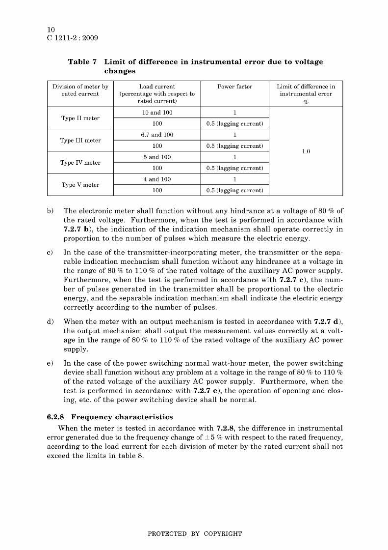
a) When the meter is tested in accordance with 7.2.7 a), the difference in instrumental error generated due to the voltage change of ± 10 % with respect to the rated voltage, according to the load current for each division of meter by the rated current shall not exceed the limits in table 7.
PROTECTED BY COPYRIGHT
10 C 1211-2 : 2009
Table 7 Limit of difference in instrumental error due to voltage changes
Division of meter by Load current Power factor Limit of difference in rated current (percentage with respect to instrumental error
rated current) %
10 and 100 1 Type II meter
100 0.5 (lagging current)
6.7 and 100 1 Type III meter
100 0.5 (lagging current) 1.0
5 and 100 1 Type IV meter
100 0.5 (lagging current)
4 and 100 1 Type V meter
100 0.5 (lagging current)
b) The electronic meter shall function without any hindrance at a voltage of 80 % of the rated voltage. Furthermore, when the test is performed in accordance with 7.2.7 b), the indication of the indication mechanism shall operate correctly in proportion to the number of pulses which measure the electric energy.
c) In the case of the transmitter-incorporating meter, the transmitter or the separable indication mechanism shall function without any hindrance at a voltage in the range of 80 % to 110 % of the rated voltage of the auxiliary AC power supply. Furthermore, when the test is performed in accordance with 7.2.7 c), the number of pulses generated in the transmitter shall be proportional to the electric energy, and the separable indication mechanism shall indicate the electric energy correctly according to the number of pulses.
d) When the meter with an output mechanism is tested in accordance with 7.2.7 d), the output mechanism shall output the measurement values correctly at a voltage in the range of 80 % to 110 % of the rated voltage of the auxiliary AC power supply.
e) In the case of the power switching normal watt-hour meter, the power switching device shall function without any problem at a voltage in the range of 80 % to 110 % of the rated voltage of the auxiliary AC power supply. Furthermore, when the test is performed in accordance with 7.2.7 e), the operation of opening and closing, etc. of the power switching device shall be normal.
6.2.8 Frequency characteristics
When the meter is tested in accordance with 7.2.8, the difference in instrumental error generated due to the frequency change of ± 5 % with respect to the rated frequency, according to the load current for each division of meter by the rated current shall not exceed the limits in table 8.
PROTECTED BY COPYRIGHT

11 C 1211-2 : 2009
Table 8 Limit of difference in instrumental error due to frequency change
Division of meter by Load current Power factor Limit of difference in rated current (percentage with respect to instrumental error
rated current) %
10 and 100 1 1.0 Type II meter
50 0.5 (lagging current) 2.0
6.7 and 100 1 1.0 Type III meter
50 0.5 (lagging current) 2.0
5 and 100 1 1.0 Type IV meter
50 0.5 (lagging current) 2.0
4 and 100 1 1.0 Type V meter
50 0.5 (lagging current) 2.0
6.2.9 Influence of external magnetic field
The influence of external magnetic field shall be as follows.
a) When the meter is tested in accordance with 7.2.9 a), the difference in instrumental error generated by giving an external magnetic field according to the load current for each division of meter by the rated current shall not exceed the limits in table 9.
Table 9 Limit of difference in instrumental error due to external magnetic field
Division of meter by Load current Limit of difference in rated current (percentage with respect to instrumental error
rated current) %
Type II meter 10
Type III meter 6.7 1.0
Type IV meter 5
Type V meter 4
b) When the transmitter-incorporating meter is tested in accordance with 7.2.9 b), the number of pulses generated in the transmitter shall be correctly proportional to the electric energy.
c) When the meter with an output mechanism is tested in accordance with 7.2.9 c), the output mechanism shall output the measurement values correctly.
d) When the power switching normal watt-hour meter is tested in accordance with 7.2.9 d), the operation of opening and closing, etc. of the power switching device shall be normal.
PROTECTED BY COPYRIGHT
12 C 1211-2 : 2009
6.2.10 Influence of waveform
When the meter is tested in accordance with 7.2.10, the difference in instrumental error generated due to the inclusion of third harmonics shall not exceed the limit of 1.0 %.
6.2.11 Influence of overcurrent
The influence of overcurrent shall be as follows.
a) When the meter is tested in accordance with 7.2.11 a), improper temperature rise, or electric or mechanical damage shall not occur, and the difference in instrumental error generated by passing overcurrent shall not exceed the limit of 1.0 %.
b) When the transmitter-incorporating meter is tested in accordance with 7.2.11 b), the number of pulses generated in the transmitter shall be correctly proportional to the electric energy.
c) When the meter with an output mechanism is tested in accordance with 7.2.11 c), the output mechanism shall output the measurement values correctly.
d) When the power switching normal watt-hour meter is tested in accordance with 7.2.11 d), the operation of opening and closing, etc. of the power switching device shall be normal.
6.2.12 Influence of reverse current
The influence of the reverse current on the induction type meter equipped with a reversal preventing device or the electronic meter equipped with a function in which reverse current is not measured shall be as follows.
a) When the meter is tested in accordance with 7.2.12 a), in the case of the induction type meter, the rotor shall stop before it rotates once, and in the case of the electronic meter, measurement pulses shall not be generated.
b) When the transmitter-incorporating meter is tested in accordance with 7.2.12 b), in the case of the induction type meter, the number of pulses generated in the transmitter shall not exceed the number of pulses generated when the rotor makes one revolution, and in the case of the electronic meter, a pulse shall not be generated in the transmitter.
c) When the meter with an output mechanism is tested in accordance with 7.2.12 c), the output mechanism shall output the measurement values correctly.
6.2.13 Influence of voltage unbalance
For the electronic meter equipped with the function of open-phase protection, when it is tested in accordance with 7.2.13, the difference of the obtained instrumental error from that in the voltage balance condition shall not exceed the limit of 4.0 %.
6.2.14 Influence of interruption to service
The influence of interruption to service shall be as follows.
a) The electronic meter, when tested in accordance with 7.2.14 a) and 7.2.14 b), shall indicate the electric energy correctly.
PROTECTED BY COPYRIGHT

13 C 1211-2 : 2009
b) The power switching device of a power switching normal watt-hour meter, when it is tested in accordance with 7.2.14 c), shall operate normally.
6.2.15 Influence of static electricity
When the electronic meter is tested in accordance with 7.2.15, during the electrostatic-discharge application, the indication 1) shall not change, and after the electrostaticdischarge application, the meter shall be free from damage and the indication 1) shall not change, and the instrumental error shall satisfy the tolerance of ± 2.0 % for power factor 1, and the tolerance of ± 2.5 % for power factor 0.5 (lagging current) according to the load current. Furthermore, the meter with an output mechanism shall output the measurement values correctly after the electrostatic-discharge application.
Note 1) It applies to the indication used in transaction or certification of the meter concerned.
6.2.16 Influence of impulsive noise
When the electronic meter is tested in accordance with 7.2.16, the difference in instrumental error generated by applying impulsive noise shall not exceed the limit of 2.0 %. Furthermore, the meter with an output mechanism shall output the measurement values correctly after impulsive noise application.
6.2.17 Influence of electromagnetic waves
When the electronic meter is tested in accordance with 7.2.17, after it is irradiated with electromagnetic waves with the rated voltage of rated frequency applied, the indication 1) of the meter shall not change, and the difference in instrumental error generated by irradiating it with electromagnetic waves shall not exceed the limit of 3.0 %. Furthermore, the meter with an output mechanism shall output the measurement values correctly after it is irradiated with electromagnetic waves.
6.3 Mechanical performance
6.3.1 Mechanism, etc.
The bearing, indication mechanism, transmitter, output mechanism and power switching device of a meter shall be as follows.
a) When the meter is tested in accordance with 7.3.1 a), the difference between the maximum and the minimum instrumental errors shall not exceed the limit of 1.0 %.
b) When the induction type meter is tested in accordance with 7.3.1 b), the difference between the average of the instrumental errors in 7.3.1 a) and the instrumental error when two counting figure drums step up at the same time shall not exceed the limit of 1.0 %.
c) When the induction type meter is tested in accordance with 7.3.1 c), the difference between instrumental errors before and after the removal of an indication mechanism shall not exceed the limit of 2.0 %.
d) When the meter is tested in accordance with 7.3.1 d), the difference of the instrumental error obtained for each lapse of 500 h from that obtained immediately after the test start shall not exceed the limit of 1.0 %.
PROTECTED BY COPYRIGHT

14 C 1211-2 : 2009
e) When the transmitter-incorporating meter is tested in accordance with 7.3.1 e), the number of pulses generated in the transmitter shall be correctly proportional to the electric energy.
f) When the meter with an output mechanism is tested in accordance with 7.3.1 f), the output mechanism shall output the measurement values correctly.
g) When the power switching normal watt-hour meter is tested in accordance with 7.3.1 g), its power switching device shall not have a short-circuit of the switch, welding of the point of contact, or any electrical or mechanical abnormality.
6.3.2 Transmitter
When the transmitter-incorporating meter is tested in accordance with 7.3.2, the number of pulses generated in the transmitter shall be correctly proportional to electric energy, and the separable indication mechanism shall indicate electric energy correctly according to the number of pulses.
6.3.3 Output mechanism
When the meter with output mechanism is tested in accordance with 7.3.3, the output mechanism shall output the measurement values correctly.
6.3.4 Influence of inclination
The influence of the inclination of the induction type meter, and the electronic meter of which the mounting posture is restricted shall be as follows.
a) When the meter is tested in accordance with 7.3.4 a), the difference of the instrumental errors from that in the normal posture shall not exceed the limits in table 10 according to the load current for each division of meter by the rated current.
Table 10 Limit of difference in instrumental error caused by inclination
Division of meter by Load current Limit of difference in rated current (percentage with respect to instrumental error
rated current) %
5 2.0 Type II meter
50 and 100 1.0
3.3 2.0 Type III meter
50 and 100 1.0
2.5 2.0 Type IV meter
50 and 100 1.0
2 2.0 Type V meter
50 and 100 1.0
b) When the transmitter-incorporating meter is tested in accordance with 7.3.4 b), the number of pulses generated in the transmitter shall be correctly proportional to the electric energy.
PROTECTED BY COPYRIGHT

15 C 1211-2 : 2009
c) When the power switching normal watt-hour meter is tested in accordance with 7.3.4 c), the operation of opening and closing, etc. of the power switching device shall be normal.
6.3.5 Influence of vibration
The influence of vibration shall be as follows.
a) The meter, when it is tested in accordance with 7.3.5 a), shall not generate mechanical damage. Furthermore, according to the load current for each division of meter by the rated current, the difference in instrumental error generated by applying the vibration shall not exceed the limits in table 11.
Table 11 Limit of difference in instrumental error caused by vibration
Division of meter by Load current Power factor Limit of difference in rated current (percentage with respect to instrumental error
rated current) %
5 1.3 1
Type II meter 50 and 100 1.0
10, 50 and 100 0.5 (lagging current) 1.3
3.3 1.3 1
Type III meter 50 and 100 1.0
6.7, 50 and 100 0.5 (lagging current) 1.3
2.5 1.3 1
Type IV meter 50 and 100 1.0
5,50 and 100 0.5 (lagging current) 1.3
2 1.3 1
Type V meter 50 and 100 1.0
4,50 and 100 0.5 (lagging current) 1.3
b) When the transmitter-incorporating meter is tested in accordance with 7.3.5 b), the number of pulses generated in the transmitter shall be correctly proportional to the electric energy.
c) When the meter with an output mechanism is tested in accordance with 7.3.5 c), the output mechanism shall output the measurement values correctly.
d) When the power switching normal watt-hour meter is tested in accordance with 7.3.5 d), the operation of opening and closing, etc. of the power switching device shall be normal.
6.3.6 Influence of impact
The influence of impact shall be as follows.
a) The meter, when tested in accordance with 7.3.6 a), shall not generate mechanical damage. Furthermore, according to the load current for each division of meter by the rated current, the difference in instrumental error generated by applying the impact shall not exceed the limits in table 12.
PROTECTED BY COPYRIGHT

16 C 1211-2 : 2009
b) When the transmitter-incorporating meter is tested in accordance with 7.3.6 b), the number of pulses generated in the transmitter shall be correctly proportional to the electric energy.
c) When the meter with an output mechanism is tested in accordance with 7.3.6 c), the output mechanism shall output the measurement values correctly.
d) When the power switching normal watt-hour meter is tested in accordance with 7.3.6 d), the operation of opening and closing, etc. of the power switching device shall be normal.
Table 12 Limit of difference in instrumental error due to impact
Division of meter by Load current Power factor Limit of difference in rated current (percentage with respect to instrumental error
rated current) %
5 1.3 1
Type II meter 50 and 100 1.0
10, 50 and 100 0.5 (lagging current) 1.3
3.3 1.3 1
Type III meter 50 and 100 1.0
6.7,50 and 100 0.5 (lagging current) 1.3
2.5 1.3 1
Type IV meter 50 and 100 1.0
5,50 and 100 0.5 (lagging current) 1.3
2 1.3 1
Type V meter 50 and 100 1.0
4,50 and 100 0.5 (lagging current) 1.3
6.3.7 Power switching device
The power switching device shall be as follows.
a) The power switching device of a power switching normal watt-hour meter, when the written amount of the money, etc. is inserted, shall indicate the numerical value of the amount of the inserted money, etc. or the electric energy equivalent to that.
b) The power switching device of a power switching normal watt-hour meter shall operate normally when the written amount of the money, etc. is inserted, and shall complete the operation when the indication mechanism indicates that the electric energy equivalent to the set amount has passed the meter concerned.
c) When the power switching normal watt-hour meter is tested in accordance with 7.3.7, the operation of opening and closing, etc. of the power switching device shall be normal, and the difference between the value obtained by subtracting the electric energy equivalent to the instrumental error from the indicated electric energy of the indication mechanism until the operation is completed and the electric energy
PROTECTED BY COPYRIGHT
17 C 1211-2 : 2009
per one unit of the written amount of money, etc. shall not exceed 0.2 % of the electric energy per one unit of the written amount of money, etc.
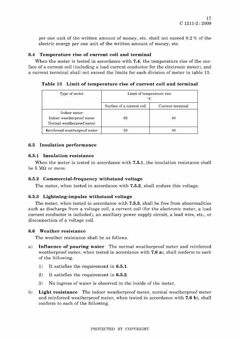
6.4 Temperature rise of current coil and terminal
When the meter is tested in accordance with 7.4, the temperature rise of the surface of a current coil (including a load current conductor for the electronic meter), and a current terminal shall not exceed the limits for each division of meter in table 13.
Table 13 Limit of temperature rise of current coil and terminal
Type of meter Limit of temperature rise °C
Surface of a current coil Current terminal
Indoor meter
Indoor weatherproof meter 65 40
Normal weatherproof meter
Reinforced weatherproof meter 55 40
6.5 Insulation performance
6.5.1 Insulation resistance
When the meter is tested in accordance with 7.5.1, the insulation resistance shall be 5 MQ or more.
6.5.2 Commercial-frequency withstand voltage
The meter, when tested in accordance with 7.5.2, shall endure this voltage.
6.5.3 Lightning-impulse withstand voltage
The meter, when tested in accordance with 7.5.3, shall be free from abnormalities such as discharge from a voltage coil, a current coil (for the electronic meter, a load current conductor is included), an auxiliary power supply circuit, a lead wire, etc., or disconnection of a voltage coil.
6.6 Weather resistance
The weather resistance shall be as follows.
a) Influence of pouring water The normal weatherproof meter and reinforced weatherproof meter, when tested in accordance with 7.6 a), shall conform to each of the following.
1) It satisfies the requirement in 6.5.1.
2) It satisfies the requirement in 6.5.2.
3) No ingress of water is observed in the inside of the meter.
b) Light resistance The indoor weatherproof meter, normal weatherproof meter and reinforced weatherproof meter, when tested in accordance with 7.6 b), shall conform to each of the following.
PROTECTED BY COPYRIGHT
18 C 1211-2 : 2009
1) When the test is performed in accordance with 7.6 b) 1), the following change shall not be observed.
Progressive rusting of a metal part
Cracking, blistering, peeling and noticeable discoloration of the painted surface
Cracking, blistering and degradation of the cover or packing
Cracking, deformation and degradation of the inside and outside of the outer case, in the case of the meter made of synthetic resin
Discoloration of the nameplate, the test label, the indicator, and the cover, of such a degree that recognition of the letters or signs in them is difficult
2) The normal weatherproof meter and reinforced weatherproof meter made of synthetic resin, when tested in accordance with 7.6 b) 2), shall be free from the following changes:
Cracking, deformation and degradation of the inside and outside of the outer case
Breakage by a spring hammer shock test
c) Influence of humidity and sulfurous acid gas The influence of humidity and sulfurous acid gas shall be as follows.
1) The normal weatherproof meter and reinforced weatherproof meter, when tested in accordance with 7.6 c) 1) and 7.6 c) 2), shall conform to each of the following.
1.1) It satisfies the requirement in 6.5.1.
1.2) It satisfies the requirement in 6.5.2.
1.3) The clearness of the indication of the indicator is not impaired due to cloudiness inside the cover continuously for 24 h or more.
1.4) When one week has elapsed following 1.3), reading the indicator is not impaired due to cloudiness caused by deposits of crystals inside the cover.
2) The normal weatherproof meter and reinforced weatherproof meter, when tested in accordance with 7.6 c) 3), shall be free from the following changes:
Progressive rusting of a metal part
Cracking, blistering, peeling and noticeable discoloration of the painted surface
Cracking, blistering and degradation of packing
Cracking, deformation and degradation of the inside and outside of the outer case in the case of the meter made of synthetic resin
3) The normal weatherproof meter and reinforced weatherproof meter made of synthetic resin, when tested in accordance with 7.6 c) 4), shall be free from breakage.
PROTECTED BY COPYRIGHT

19 C 1211-2 : 2009
d) Influence of salt spray The influence of salt spray shall be as follows.
1) The normal weatherproof meter and reinforced weatherproof meter, when tested in accordance with 7.6 d) 1), shall be free from the following changes:
Noticeable and progressive rusting of a metal part and progressive rusting for the reinforced weatherproof meter
Cracking, blistering, peeling and noticeable discoloration of the painted surface
Cracking, blistering and degradation of packing
Cracking, deformation and degradation of the inside and outside of the outer case in the case of the meter made of synthetic resin
2) The normal weatherproof meter and reinforced weatherproof meter made of synthetic resin, when tested in accordance with 7.6 d) 2), shall be free from breakage.
e) Influence of packing aging The influence of packing aging shall be as follows.
1) The normal weatherproof meter and reinforced weatherproof meter, when tested in accordance with 7.6 e) 1), shall conform to each of the following.
1.1) It satisfies the requirement in 6.5.1.
1.2) It satisfies the requirement in 6.5.2.
1.3) No ingress of water is observed in the inside of the meter.
1.4) There is be no cracking, blistering, degradation of packing or defect in packing effect.
1.5) In the case of the meter made of synthetic resin, there is no cracking, deformation or degradation in the packing or on the inside and outside of the outer case.
2) The normal weatherproof meter and reinforced weatherproof meter made of synthetic resin, when tested in accordance with 7.6 e) 2), shall be free from breakage.
f) Influence of high temperature and rapid cooling The normal weatherproof meter and reinforced weatherproof meter, when tested in accordance with 7.6 f), shall be free from abnormalities such as cracks in the glass part of the cover and if it is a meter made of synthetic resin, on the inside and the outside of the outer case.
g) Influence of high temperature and high humidity When the electronic meter is tested in accordance with 7.6 g), the difference of the obtained instrumental error from that in the standard state 2) shall not exceed the limit of 2.4 % for power factor 1 and the limit of 3.0 % for power factor 0.5 (lagging current).
Note 2) The standard state refers to the state of the meter after it was left to stand in air at a temperature of 23°C and a humidity of 65 % for 3 h.
PROTECTED BY COPYRIGHT
20 C 1211-2 : 2009
h) Influence of temperature cycle When the electronic meter is tested in accordance with 7.6 h), the difference in instrumental error with respect to the instrumental error measured at the test start at the temperature of 23°C shall not exceed the limit of 1.0 %.
i) Thickness of paint film When the reinforced weatherproof meter (except for those made of synthetic resin) is tested in accordance with 7.6 i), the paint film thickness of the outer case shall be 30 ~m or more.
6.7 Material
The material shall be as follows.
a) The outer case (base, cover and terminal cover) of the meter made of synthetic resin, the terminal box or the test piece, when they are tested in accordance with 7.7 a), shall be free from flame or red heat by contact of a glow wire, or after a glow wire is removed, flame or red heat shall disappear within 30 s without burning out the outer case and terminal box or the test piece. In the case of the test using a test piece, there shall be no burnt deposit in the wooden board placed under the test piece and a thin paper shall not be ignited.
b) The outer case (base, cover surface including a window and terminal cover) of the meter made of synthetic resin, when it is tested in accordance with 7.7 b), shall not be broken. Furthermore, the meter shall be free from any defects in the function.
7 Test methods
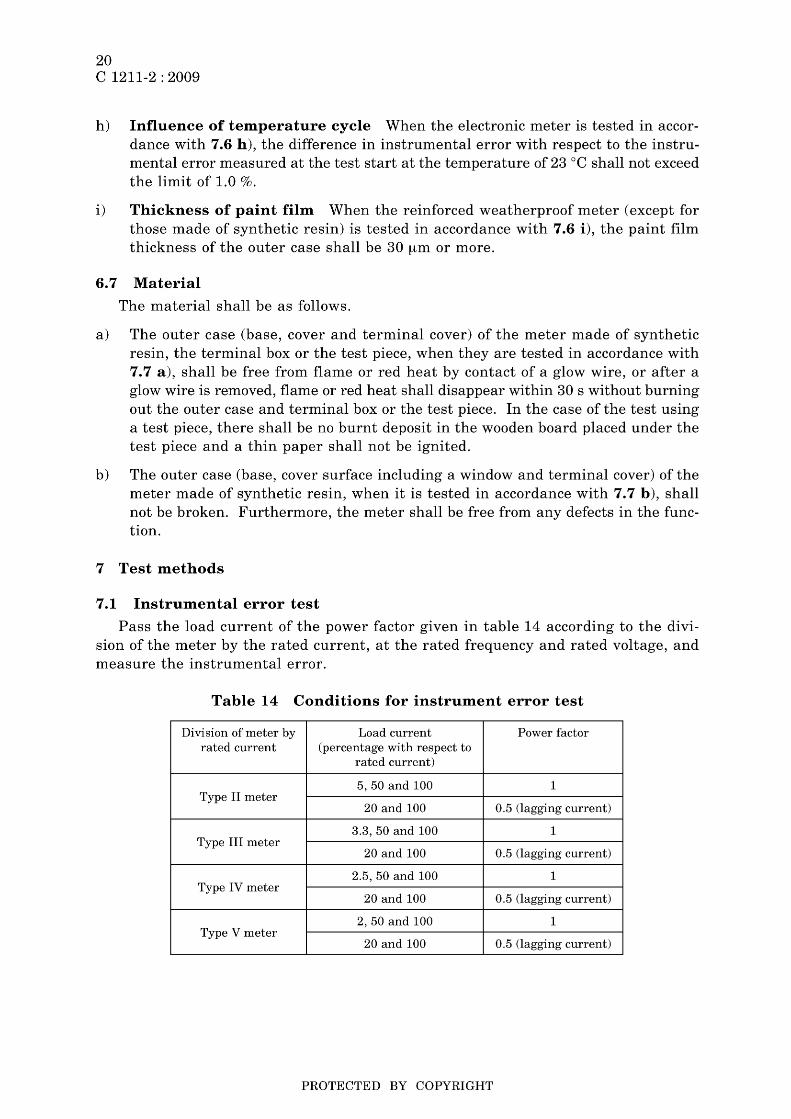
7.1 Instrumental error test
Pass the load current of the power factor given in table 14 according to the division of the meter by the rated current, at the rated frequency and rated voltage, and measure the instrumental error.
Table 14 Conditions for instrument error test
Division of meter by Load current Power factor rated current (percentage with respect to
rated current)
5,50 and 100 1 Type II meter
20 and 100 0.5 (lagging current)
3.3, 50 and 100 1 Type III meter
20 and 100 0.5 (lagging current)
2.5, 50 and 100 1 Type IV meter
20 and 100 0.5 (lagging current)
2,50 and 100 1 Type V meter
20 and 100 0.5 (lagging current)
PROTECTED BY COPYRIGHT

7.2 Test of electrical performance
7.2.1 Start-up
21 C 1211-2 : 2009
Pass the load current of power factor 1 given in table 15 according to the division of the meter by the rated current, at the rated frequency and rated voltage. In the case of the induction type meter, examine if the rotor makes one or more revolutions. In the case of the electronic meter, calculate the number of the measurement pulses generated during 10 s from the meter constant, and if the obtained number of pulses is less than 2 pulses, examine if the measurement pulse is generated in succession for a period of time required for 2 or more pulses to be generated, and if the obtained number of pulses is 2 pulses or more, for the duration of 10 s.
Table 15 Conditions for start-up test
Division of meter by Load current rated current (ratio with respect to rated current)
Type II meter 1/250
Type III meter 1/375
Type IV meter 1/500
Type V meter 11625
7.2.2 Creeping
Apply the voltage of 110 % of the rated voltage at the rated frequency, and examine if the rotor of an induction type meter stops before it rotates once. For the electronic meter, examine if the measurement pulse is not generated for 90 s when the time calculated according to the following formula is 90 s or less, and for the time obtained as the calculated result when it is more than 90 s.
where, k: meter constant (pulse/kWs)
m: measurement element number
Un: rated voltage (V)
In: rated current (A)
7.2.3 Influence of self-heating
The test shall be performed as follows.
a) After applying the rated voltage for 1 h at the rated frequency, when further passing the rated currents of power factor 1 and 0.5 (lagging current), obtain the difference between instrumental error measured immediately after passing the rated current and that measured 30 min thereafter, and between the instrumental error measured 30 min and that measured 120 min after passing the rated current, respectively.
PROTECTED BY COPYRIGHT
22 C 1211-2 : 2009
b) While applying the rated voltage at the rated frequency, when passing the rated currents of power factor 1 and 0.5 (lagging current), obtain the difference between the instrumental error measured immediately after passing the rated current and that measured 30 min thereafter, and between the instrumental error measured 30 min and that measured 120 min after passing the rated current, respectively.
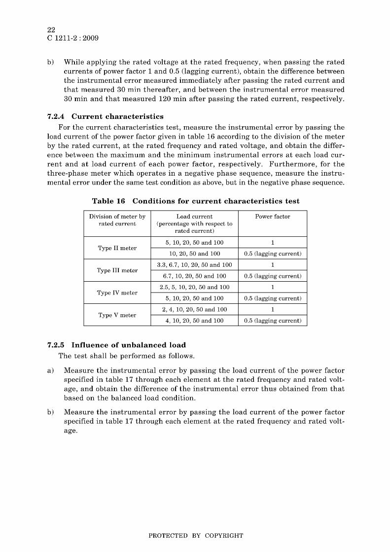
7.2.4 Current characteristics
For the current characteristics test, measure the instrumental error by passing the load current of the power factor given in table 16 according to the division of the meter by the rated current, at the rated frequency and rated voltage, and obtain the difference between the maximum and the minimum instrumental errors at each load current and at load current of each power factor, respectively. Furthermore, for the three-phase meter which operates in a negative phase sequence, measure the instrumental error under the same test condition as above, but in the negative phase sequence.
Table 16 Conditions for current characteristics test
Di vision of meter by Load current rated current (percentage with respect to
rated current)
5, 10, 20, 50 and 100 Type II meter
10, 20, 50 and 100
3.3,6.7,10,20,50 and 100 Type III meter
6.7,10,20,50 and 100
2.5, 5, 10, 20, 50 and 100 Type IV meter
5, 10, 20, 50 and 100
2, 4, 10, 20, 50 and 100 Type V meter
4, 10, 20, 50 and 100
7.2.5 Influence of unbalanced load
The test shall be performed as follows.
Power factor
1
0.5 (lagging current)
1
0.5 (lagging current)
1
0.5 (lagging current)
1
0.5 (lagging current)
a) Measure the instrumental error by passing the load current of the power factor specified in table 17 through each element at the rated frequency and rated voltage, and obtain the difference of the instrumental error thus obtained from that based on the balanced load condition.
b) Measure the instrumental error by passing the load current of the power factor specified in table 17 through each element at the rated frequency and rated voltage.
PROTECTED BY COPYRIGHT
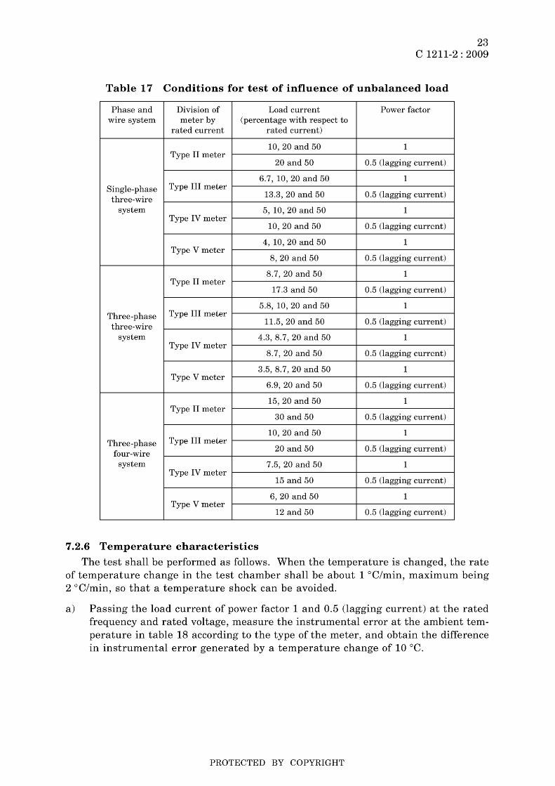
23 C 1211-2 : 2009
Table 17 Conditions for test of influence of unbalanced load
Phase and Division of Load current Power factor wire system meter by (percentage with respect to
rated current rated current)
10,20 and 50 1 Type II meter
20 and 50 0.5 (lagging current)
6.7, 10, 20 and 50 1 Single-phase Type III meter
three-wire 13.3, 20 and 50 0.5 (lagging current)
system 5, 10, 20 and 50 1 Type IV meter
10,20 and 50 0.5 (lagging current)
4, 10, 20 and 50 1 Type V meter
8,20 and 50 0.5 (lagging current)
8.7, 20 and 50 1 Type II meter
17.3 and 50 0.5 (lagging current)
5.8, 10, 20 and 50 1 Three-phase Type III meter
three-wire 11.5, 20 and 50 0.5 (lagging current)
system 4.3, 8.7, 20 and 50 1 Type IV meter
8.7,20 and 50 0.5 (lagging current)
3.5, 8.7, 20 and 50 1 Type V meter
6.9, 20 and 50 0.5 (lagging current)
15,20 and 50 1 Type II meter
30 and 50 0.5 (lagging current)
10,20 and 50 1 Three-phase Type III meter
four-wire 20 and 50 0.5 (lagging current)
system 7.5, 20 and 50 1 Type IV meter
15 and 50 0.5 (lagging current)
6,20 and 50 1 Type V meter
12 and 50 0.5 (lagging current)
7.2.6 Temperature characteristics
The test shall be performed as follows. When the temperature is changed, the rate of temperature change in the test chamber shall be about 1 °C/min, maximum being 2 °C/min, so that a temperature shock can be avoided.
a) Passing the load current of power factor 1 and 0.5 (lagging current) at the rated frequency and rated voltage, measure the instrumental error at the ambient temperature in table 18 according to the type of the meter, and obtain the difference in instrumental error generated by a temperature change of 10°C.
PROTECTED BY COPYRIGHT

24 C 1211-2 : 2009
Table 18 Conditions for temperature characteristics test
Type of meter Ambient temperature
°C
Indoor meter
Indoor weatherproof meter -10,0, 10, 20, 30 and 40
Normal weatherproof meter
Reinforced weatherproof meter -10,0, 10, 20, 30, 40 and 50
b) For the transmitter-incorporating meter, in addition to the test in 7.2.6 a), pass the rated currents of power factor 1 and 0.5 (lagging current) at the rated frequency and rated voltage, and measure the number of pulses generated at the transmitter with the ambient temperature kept at -10°C and 40°C (50°C for the reinforced weatherproof meter), respectively.
c) For the test of the meter with an output mechanism, in addition to the test in 7.2.6 a), when applying the rated frequency and rated voltage at -10°C and 40°C (50°C for the reinforced weatherproof meter), the output mechanism shall output the measurement values correctly.
d) For the test of the power switching normal watt-hour meter, in addition to the test in 7.2.6 a), pass the rated currents of power factor 1 and 0.5 (lagging current) at the rated frequency and rated voltage at a temperature of -10°C and 40°C, and examine if the power switching device correctly operates when the money, etc. of which the amount is written on the power switching device is inserted.
7.2.7 Voltage characteristics
The test shall be performed as follows.
a) Change the voltage to 90 %, 100 % and 110 % of the rated voltage at the rated frequency, and pass the load current of the power factor given in table 19 according to the division of the meter by the rated current. Measure the instrumental error, and obtain the difference in instrumental error generated by the voltage change from the rated voltage.
Table 19 Conditions for voltage characteristics test
Division of meter by Load current Power factor rated current (percentage with respect to
rated current)
10 and 100 1 Type II meter
100 0.5 (lagging current)
6.7 and 100 1 Type III meter
100 0.5 (lagging current)
5 and 100 1 Type IV meter
100 0.5 (lagging current)
4 and 100 1 Type V meter
100 0.5 (lagging current)
PROTECTED BY COPYRIGHT

25 C 1211-2 : 2009
b) For the test of the electronic meter, in addition to the test in 7.2.7 a), pass the rated current of power factor 1 at the voltage of 80 % of the rated voltage at the rated frequency, measure the number of pulses which measure the electric energy, and examine the indication of the indication mechanism.
c) For the test of the transmitter-incorporating meter, in addition to the test in 7.2.7 a), apply the voltages of 80 % and 110 % of the rated voltage of the auxiliary AC power supply, and measure the number of pulses generated in the transmitter.
d) For the test of the meter with an output mechanism, in addition to the test in 7.2.7 a), apply the voltages of 80 % and 110 % of the rated voltage of the auxiliary AC power supply, and examine if the output mechanism outputs the measurement values correctly.
e) For the test of the power switching normal watt-hour meter, in addition to the test in 7.2.7 a), apply the voltages of 80 % and 110 % of the rated voltage of the auxiliary AC power supply, and examine if the power switching device operates correctly when the money, etc. of which the amount is written on the power switching device is inserted.
7.2.8 Frequency characteristics
Change the frequency to 95 %, 100 % and 105 % of the rated frequency at the rated voltage, and pass the load current of the power factor given in table 20 according to the division of the meter by the rated current. Measure the instrumental error, and obtain the difference in instrumental error generated by the frequency change from the rated frequency.
Table 20 Conditions for frequency characteristics test
Division of meter by Load current rated current (percentage with respect to
rated current)
10 and 100 Type II meter
50
6.7 and 100 Type III meter
50
5 and 100 Type IV meter
50
4 and 100 Type V meter
50
7.2.9 Influence of external magnetic field
The test shall be performed as follows.
Power factor
1
0.5 (lagging current)
1
0.5 (lagging current)
1
0.5 (lagging current)
1
0.5 (lagging current)
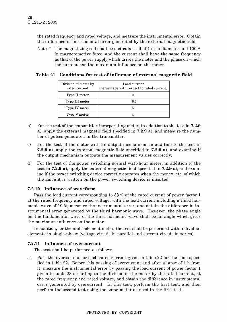
a) With the meter placed at the center of the magnetizing coiI 3), apply the magnetic field generated by the coil to the meter in the direction where the magnetic field has the maximum influence on the meter. Pass the load current, of power factor 1 given in table 21 according to the division of the meter by the rated current, at
PROTECTED BY COPYRIGHT
26 C 1211-2 : 2009
the rated frequency and rated voltage, and measure the instrumental error. Obtain the difference in instrumental error generated by the external magnetic field.
Note 3) The magnetizing coil shall be a circular coil of 1 m in diameter and 100 A in magnetomotive force, and the current shall have the same frequency as that of the power supply which drives the meter and the phase on which the current has the maximum influence on the meter.
Table 21 Conditions for test of influence of external magnetic field
Division of meter by Load current rated current (percentage with respect to rated current)
Type II meter 10
Type III meter 6.7
Type IV meter 5
Type V meter 4
b) For the test of the transmitter-incorporating meter, in addition to the test in 7.2.9 a), apply the external magnetic field specified in 7.2.9 a), and measure the number of pulses generated in the transmitter.
c) For the test of the meter with an output mechanism, in addition to the test in 7.2.9 a), apply the external magnetic field specified in 7.2.9 a), and examine if the output mechanism outputs the measurement values correctly.
d) For the test of the power switching normal watt-hour meter, in addition to the test in 7.2.9 a), apply the external magnetic field specified in 7.2.9 a), and examine if the power switching device correctly operates when the money, etc. of which the amount is written on the power switching device is inserted.
7.2.10 Influence of waveform
Pass the load current corresponding to 33 % of the rated current of power factor 1 at the rated frequency and rated voltage, with the load current including a third harmonic wave of 10 %, measure the instrumental error, and obtain the difference in instrumental error generated by the third harmonic wave. However, the phase angle for the fundamental wave of the third harmonic wave shall be an angle which gives the maximum influence on the meter.
In addition, for the multi-element meter, the test shall be performed with individual elements in single-phase (voltage circuit in parallel and current circuit in series).
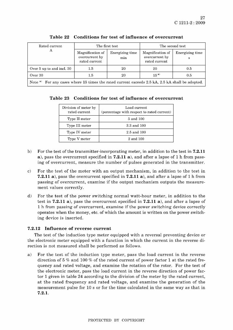
7.2.11 Influence of overcurrent The test shall be performed as follows.
a) Pass the overcurrent for each rated current given in table 22 for the time specified in table 22. Before this passing of overcurrent and after a lapse of 1 h from it, measure the instrumental error by passing the load current of power factor 1 given in table 23 according to the division of the meter by the rated current, at the rated frequency and rated voltage, and obtain the difference in instrumental error generated by overcurrent. In this test, perform the first test, and then perform the second test using the same meter as used in the first test.
PROTECTED BY COPYRIGHT
27 C 1211-2 : 2009
Table 22 Conditions for test of influence of overcurrent
Rated current The first test The second test A
Magnification of Energizing time Magnification of Energizing time overcurrent by min overcurrent by s rated current rated current
Over 5 up to and incl. 30 1.5 20 20 0.5
Over 30 1.5 20 15 a) 0.5
Note a) For any cases where 15 times the rated current exceeds 2.5 kA, 2.5 kA shall be adopted.
Table 23 Conditions for test of influence of overcurrent
Division of meter by Load current rated current (percentage with respect to rated current)
Type II meter 5 and 100
Type III meter 3.3 and 100
Type IV meter 2.5 and 100
Type V meter 2 and 100
b) For the test of the transmitter-incorporating meter, in addition to the test in 7.2.11 a), pass the overcurrent specified in 7.2.11 a), and after a lapse of 1 h from passing of overcurrent, measure the number of pulses generated in the transmitter.
c) For the test of the meter with an output mechanism, in addition to the test in 7.2.11 a), pass the overcurrent specified in 7.2.11 a), and after a lapse of 1 h from passing of overcurrent, examine if the output mechanism outputs the measurement values correctly.
d) For the test of the power switching normal watt-hour meter, in addition to the test in 7.2.11 a), pass the overcurrent specified in 7.2.11 a), and after a lapse of 1 h from passing of overcurrent, examine if the power switching device correctly operates when the money, etc. of which the amount is written on the power switching device is inserted.
7.2.12 Influence of reverse current
The test of the induction type meter equipped with a reversal preventing device or the electronic meter equipped with a function in which the current in the reverse direction is not measured shall be performed as follows.
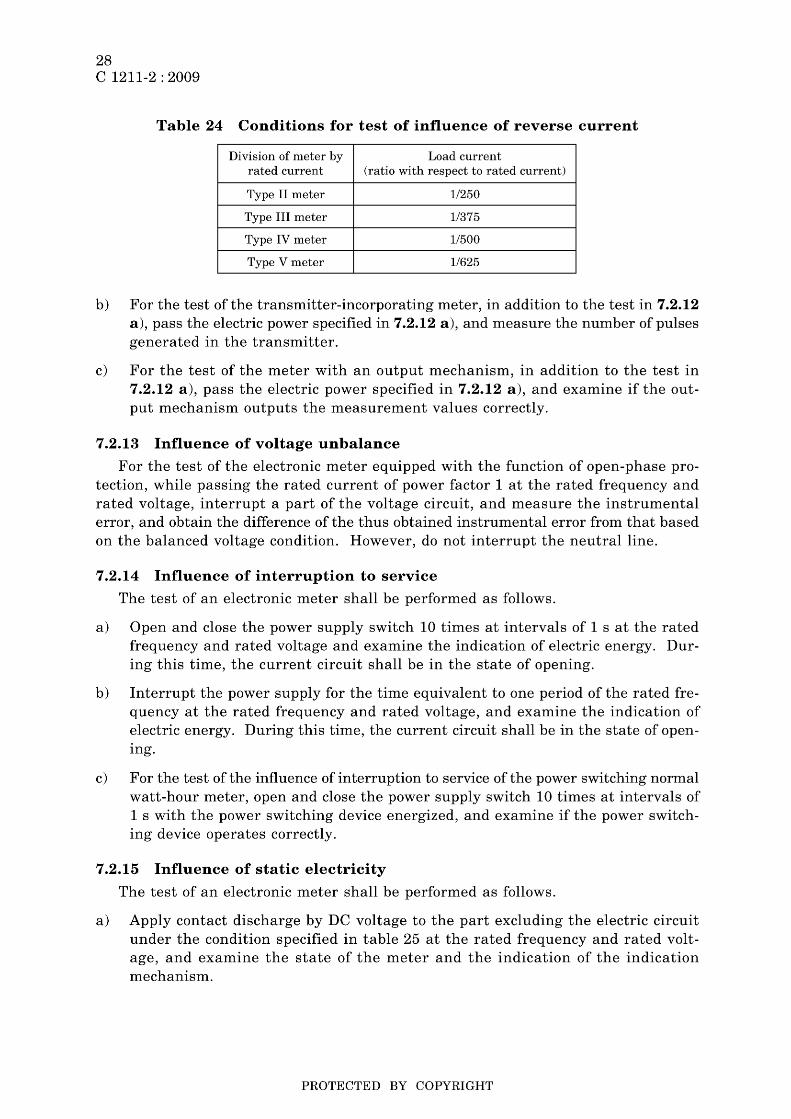
a) For the test of the induction type meter, pass the load current in the reverse direction of 5 % and 100 % of the rated current of power factor 1 at the rated frequency and rated voltage, and examine the rotation of the rotor. For the test of the electronic meter, pass the load current in the reverse direction of power factor 1 given in table 24 according to the division of the meter by the rated current, at the rated frequency and rated voltage, and examine the generation of the measurement pulse for 10 s or for the time calculated in the same way as that in 7.2.1.
PROTECTED BY COPYRIGHT
28 C 1211-2 : 2009
Table 24 Conditions for test of influence of reverse current
Division of meter by Load current rated current (ratio with respect to rated current)
Type II meter 1/250
Type III meter 1/375
Type IV meter 1/500
Type V meter 11625
b) For the test of the transmitter-incorporating meter, in addition to the test in 7.2.12 a), pass the electric power specified in 7.2.12 a), and measure the number of pulses generated in the transmitter.
c) For the test of the meter with an output mechanism, in addition to the test in 7.2.12 a), pass the electric power specified in 7.2.12 a), and examine if the output mechanism outputs the measurement values correctly.
7.2.13 Influence of voltage unbalance
For the test of the electronic meter equipped with the function of open-phase protection, while passing the rated current of power factor 1 at the rated frequency and rated voltage, interrupt a part of the voltage circuit, and measure the instrumental error, and obtain the difference of the thus obtained instrumental error from that based on the balanced voltage condition. However, do not interrupt the neutral line.
7.2.14 Influence of interruption to service
The test of an electronic meter shall be performed as follows.
a) Open and close the power supply switch 10 times at intervals of 1 s at the rated frequency and rated voltage and examine the indication of electric energy. During this time, the current circuit shall be in the state of opening.
b) Interrupt the power supply for the time equivalent to one period of the rated frequency at the rated frequency and rated voltage, and examine the indication of electric energy. During this time, the current circuit shall be in the state of opening.
c) For the test of the influence of interruption to service of the power switching normal watt-hour meter, open and close the power supply switch 10 times at intervals of 1 s with the power switching device energized, and examine if the power switching device operates correctly.
7.2.15 Influence of static electricity
The test of an electronic meter shall be performed as follows.
a) Apply contact discharge by DC voltage to the part excluding the electric circuit under the condition specified in table 25 at the rated frequency and rated voltage, and examine the state of the meter and the indication of the indication mechanism.
PROTECTED BY COPYRIGHT

29 C 1211-2 : 2009
b) In addition to the test in 7.2.15 a), when applying the electrostatic discharge specified in 7.2.15 a), pass the load current of the power factor specified in table 26 at the rated frequency and rated voltage, and measure the instrumental error before and after application of electrostatic discharge.
c) For the test of the meter with an output mechanism, in addition to the tests in 7.2.15 a) and 7.2.15 b), after applying the electrostatic discharge specified in 7.2.15 a), examine if the output mechanism outputs the measurement values correctly.
Table 25 Conditions of electrostatic discharge
Item Conditions
Electrostatic capacity 150 pF
N umber of times of discharge 10 times
Discharge gap Continuously at intervals of 1 s min.
Applied voltage in contact discharge 8 kV in DC voltage
Discharge resistance 330 Q
Table 26 Conditions for test of influence of static electricity
Division of meter by Load current Power factor rated current (percentage with respect to
rated current)
5 and 100 1 Type II meter
100 0.5 (lagging)
3.3 and 100 1 Type III meter
100 0.5 (lagging)
2.5 and 100 1 Type IV meter
100 0.5 (lagging)
2 and 100 1 Type V meter
100 0.5 (lagging)
7.2.16 Influence of impulsive noise The test of an electronic meter shall be performed as follows.
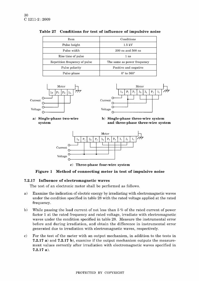
a) Measure the instrumental error while passing the load current of not less than 5 % of the rated current of power factor 1 at the rated frequency and rated voltage (for the single-phase three-wire system meter and three-phase meter, singlephase voltage equal to the rated voltage), and applying the impulsive noise between the voltage circuit and the base, and between the current circuit and the base as shown in figure 1 under the condition specified in table 27 using a pulse generator of 50 Q in output impedance, and then obtain the difference in instrumental error generated by applying the impulsive noise, respectively.
b) For the test of the meter with an output mechanism, in addition to the test in 7.2.16 a), after applying the impulsive noise specified in 7.2.16 a), examine if the output mechanism outputs the measurement values correctly.
PROTECTED BY COPYRIGHT
30 C 1211-2 : 2009
Table 27 Conditions for test of influence of impulsive noise
Item Conditions
Pulse height 1.5 kV
Pulse width 200 ns and 500 ns
Rise time of pulse 1 ns
Repetition frequency of pulse The same as power frequency
Pulse polarity Positive and negative
Pulse phase 0° to 360°
Current Current
Voltage Voltage
a) Single-phase two-wire system
Current
Voltage
b) Single-phase three-wire system and three-phase three-wire system
c) Three-phase four-wire system
Figure 1 Method of connecting meter in test of impulsive noise
7.2.17 Influence of electromagnetic waves
The test of an electronic meter shall be performed as follows.
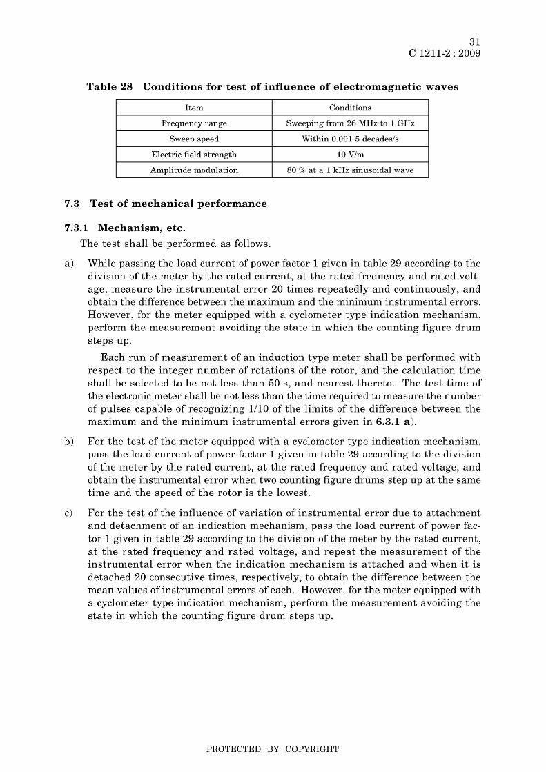
a) Examine the indication of electric energy by irradiating with electromagnetic waves under the condition specified in table 28 with the rated voltage applied at the rated frequency.
b) While passing the load current of not less than 5 % of the rated current of power factor 1 at the rated frequency and rated voltage, irradiate with electromagnetic waves under the condition specified in table 28. Measure the instrumental error before and during irradiation, and obtain the difference in instrumental error generated due to irradiation with electromagnetic waves, respectively.
c) For the test of the meter with an output mechanism, in addition to the tests in 7.2.17 a) and 7.2.17 b), examine if the output mechanism outputs the measurement values correctly after irradiation with electromagnetic waves specified in 7.2.17 a).
PROTECTED BY COPYRIGHT
31 C 1211-2 : 2009
Table 28 Conditions for test of influence of electromagnetic waves
Item Conditions
Frequency range Sweeping from 26 MHz to 1 GHz
Sweep speed Within 0.001 5 decades/s
Electric field strength 10V/m
Amplitude modulation 80 % at a 1 kHz sinusoidal wave
7.3 Test of mechanical performance
7.3.1 Mechanism, etc.
The test shall be performed as follows.
a) While passing the load current of power factor 1 given in table 29 according to the division of the meter by the rated current, at the rated frequency and rated voltage, measure the instrumental error 20 times repeatedly and continuously, and obtain the difference between the maximum and the minimum instrumental errors. However, for the meter equipped with a cyclometer type indication mechanism, perform the measurement avoiding the state in which the counting figure drum steps up.
Each run of measurement of an induction type meter shall be performed with respect to the integer number of rotations of the rotor, and the calculation time shall be selected to be not less than 50 s, and nearest thereto. The test time of the electronic meter shall be not less than the time required to measure the number of pulses capable of recognizing 1/10 of the limits of the difference between the maximum and the minimum instrumental errors given in 6.3.1 a).
b) For the test of the meter equipped with a cyclometer type indication mechanism, pass the load current of power factor 1 given in table 29 according to the division of the meter by the rated current, at the rated frequency and rated voltage, and obtain the instrumental error when two counting figure drums step up at the same time and the speed of the rotor is the lowest.
c) For the test of the influence of variation of instrumental error due to attachment and detachment of an indication mechanism, pass the load current of power factor 1 given in table 29 according to the division of the meter by the rated current, at the rated frequency and rated voltage, and repeat the measurement of the instrumental error when the indication mechanism is attached and when it is detached 20 consecutive times, respectively, to obtain the difference between the mean values of instrumental errors of each. However, for the meter equipped with a cyclometer type indication mechanism, perform the measurement avoiding the state in which the counting figure drum steps up.
PROTECTED BY COPYRIGHT

32 C 1211-2 : 2009
Table 29 Conditions for test of influence of light load instrumental error variation and detachment/attachment of indication mechanism
Division of meter by Load current rated current (percentage with respect to rated current)
Type II meter 5
Type III meter 3.3
Type IV meter 2.5
Type V meter 2
d) For the test of the influence of continuous operation, apply the impact of maximum acceleration 500 m/s2 to the meter once in each of the two directions (parallel and perpendicular to the rotor axis), in the case of the induction type meter, and apply the temperature cycle in 7.6 h) to the meter once, in the case of the electronic meter, and while passing the rated current of power factor 1 at the rated frequency and rated voltage and running the meter for 1 000 h continuous operation, measure the instrumental error immediately after the test start and in each lapse of 500 h according to the following method. Obtain the average value of the instrumental errors for each lapse of 500 h from after the test start, and obtain the difference between averages of each.
1) For the test of each elapsed time, at the rated frequency and rated voltage, pass the load current of power factor 1 given in table 30 according to the division of the meter by the rated current.
2) Test the meter according to 7.2.1, 7.2.2 and 7.3.1 a) before and after this test.
Table 30 Conditions for test of influence of continuous operation
Division of meter by Load current rated current (percentage with respect to rated current)
Type II meter 5 and 100
Type III meter 3.3 and 100
Type IV meter 2.5 and 100
Type V meter 2 and 100
e) Test the transmitter-incorporating meter in accordance with 7.3.1 d), and measure the number of pulses generated in the transmitter.
f) Test the meter with an output mechanism in accordance with 7.3.1 d) and examine if the output mechanism outputs the measurement values correctly.
g) For the test of the power switching normal watt-hour meter, in addition to the tests in 7.3.1 a) and 7.3.1 d), while passing the rated current of power factor 1 at the rated frequency and rated voltage, perform the opening and closing operation of the power switching device 5 000 times, and then examine if the power switching device correctly operates when the money, etc. of which the amount is written on the power switching device is inserted.
PROTECTED BY COPYRIGHT

7.3.2 Transmitter
33 C 1211-2 : 2009
For the test of the transmitter, while passing the rated current of power factor 1 at the rated frequency and rated voltage, and applying the rated voltage of the auxiliary AC power supply to the transmitter, measure the number of pulses generated in the transmitter. Furthermore, examine if the separable indication mechanism indicates the electric energy correctly.
7.3.3 Output mechanism
For the test of the output mechanism, pass the rated current of power factor 1 at the rated frequency and rated voltage, and apply the rated voltage of the auxiliary AC power supply to the output mechanism, to examine if the output mechanism outputs the measurement values correctly.
7.3.4 Influence of inclination
The test shall be performed as follows.
a) While passing the load current of power factor 1 given in table 31 according to the division of the meter by the rated current at the rated frequency and rated voltage, measure the instrumental error at each 3° inclination of the meter from the normal posture toward the frontward, backward, right and left directions, and obtain the difference between the errors at respective inclined postures and the error at the normal posture, respectively.
Table 31 Conditions for test of influence of inclination
Division of meter by Load current rated current (percentage with respect to rated current)
Type II meter 5,50 and 100
Type III meter 3.3, 50 and 100
Type IV meter 2.5, 50 and 100
Type V meter 2,50 and 100
b) For the test of the transmitter-incorporating meter, in addition to the test in 7.3.4 a), apply the inclination specified in 7.3.4 a), and measure the number of pulses generated in the transmitter.
c) For the test of the power switching normal watt-hour meter, in addition to the test in 7.3.4 a), apply the inclination specified in 7.3.4 a), and examine if the power switching device operates correctly when the money, etc. of which the amount is written on the power switching device is inserted.
7.3.5 Influence of vibration The test shall be performed as follows.
a) When vibration of 16.7 Hz in frequency and 4 mm in total amplitude (peak-to-peak amplitude) is applied to the meter for 1 h in each of the upward and downward, right and left, and forward and backward directions with respect to the normal posture of the meter in accordance with the method in JIS C 60068-2-6, examine if there is any mechanical damage due to application of each vibration. Further,
PROTECTED BY COPYRIGHT
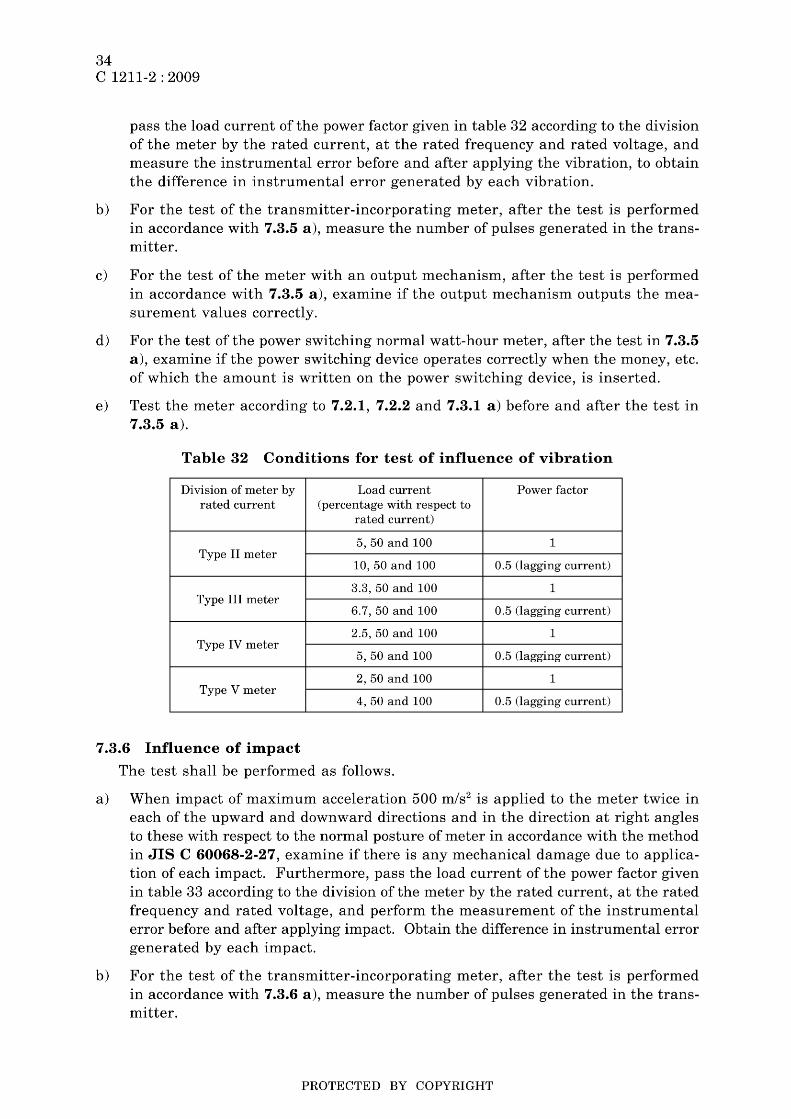
34 C 1211-2 : 2009
pass the load current of the power factor given in table 32 according to the division of the meter by the rated current, at the rated frequency and rated voltage, and measure the instrumental error before and after applying the vibration, to obtain the difference in instrumental error generated by each vibration.
b) For the test of the transmitter-incorporating meter, after the test is performed in accordance with 7.3.5 a), measure the number of pulses generated in the transmitter.
c) For the test of the meter with an output mechanism, after the test is performed in accordance with 7.3.5 a), examine if the output mechanism outputs the measurement values correctly.
d) For the test of the power switching normal watt-hour meter, after the test in 7.3.5 a), examine if the power switching device operates correctly when the money, etc. of which the amount is written on the power switching device, is inserted.
e) Test the meter according to 7.2.1, 7.2.2 and 7.3.1 a) before and after the test in 7.3.5 a).
Table 32 Conditions for test of influence of vibration
Division of meter by Load current Power factor rated current (percentage with respect to
rated current)
5,50 and 100 1 Type II meter
10, 50 and 100 0.5 (lagging current)
3.3, 50 and 100 1 Type III meter
6.7,50 and 100 0.5 (lagging current)
2.5, 50 and 100 1 Type IV meter
5,50 and 100 0.5 (lagging current)
2,50 and 100 1 Type V meter
4,50 and 100 0.5 (lagging current)
7.3.6 Influence of impact
The test shall be performed as follows.
a) When impact of maximum acceleration 500 m/s2 is applied to the meter twice in each of the upward and downward directions and in the direction at right angles to these with respect to the normal posture of meter in accordance with the method in JIS C 60068-2-27, examine if there is any mechanical damage due to application of each impact. Furthermore, pass the load current of the power factor given in table 33 according to the division of the meter by the rated current, at the rated frequency and rated voltage, and perform the measurement of the instrumental error before and after applying impact. Obtain the difference in instrumental error generated by each impact.
b) For the test of the transmitter-incorporating meter, after the test is performed in accordance with 7.3.6 a), measure the number of pulses generated in the transmitter.
PROTECTED BY COPYRIGHT
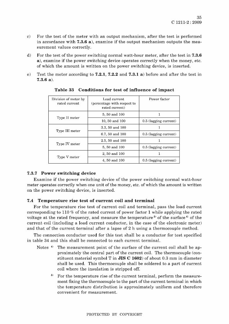
35 C 1211-2 : 2009
c) For the test of the meter with an output mechanism, after the test is performed in accordance with 7.3.6 a), examine if the output mechanism outputs the measurement values correctly.
d) For the test of the power switching normal watt-hour meter, after the test in 7.3.6 a), examine if the power switching device operates correctly when the money, etc. of which the amount is written on the power switching device, is inserted.
e) Test the meter according to 7.2.1, 7.2.2 and 7.3.1 a) before and after the test in 7.3.6 a).
Table 33 Conditions for test of influence of impact
Division of meter by Load current Power factor rated current (percentage with respect to
rated current)
5,50 and 100 1 Type II meter
10, 50 and 100 0.5 (lagging current)
3.3, 50 and 100 1 Type III meter
6.7, 50 and 100 0.5 (lagging current)
2.5, 50 and 100 1 Type IV meter
5,50 and 100 0.5 (lagging current)
2,50 and 100 1 Type V meter
4,50 and 100 0.5 (lagging current)
7.3.7 Power switching device
Examine if the power switching device of the power switching normal watt-hour meter operates correctly when one unit of the money, etc. of which the amount is written on the power switching device, is inserted.
7.4 Temperature rise test of current coil and terminal
For the temperature rise test of current coil and terminal, pass the load current corresponding to 110 % of the rated current of power factor 1 while applying the rated voltage at the rated frequency, and measure the temperature 5) of the surface 4) of the current coil (including a load current conductor, in the case of the electronic meter) and that of the current terminal after a lapse of 2 h using a thermocouple method.
The connection conductor used for this test shall be a conductor for test specified in table 34 and this shall be connected to each current terminal.
Notes 4) The measurement point of the surface of the current coil shall be approximately the central part of the current coil. The thermocouple (constituent material symbol T in JIS C 1602) of about 0.3 mm in diameter shall be used. This thermocouple shall be soldered to a part of current coil where the insulation is stripped off.
5) For the temperature rise of the current terminal, perform the measurement fixing the thermocouple to the part of the current terminal in which the temperature distribution is approximately uniform and therefore convenient for measurement.
PROTECTED BY COPYRIGHT
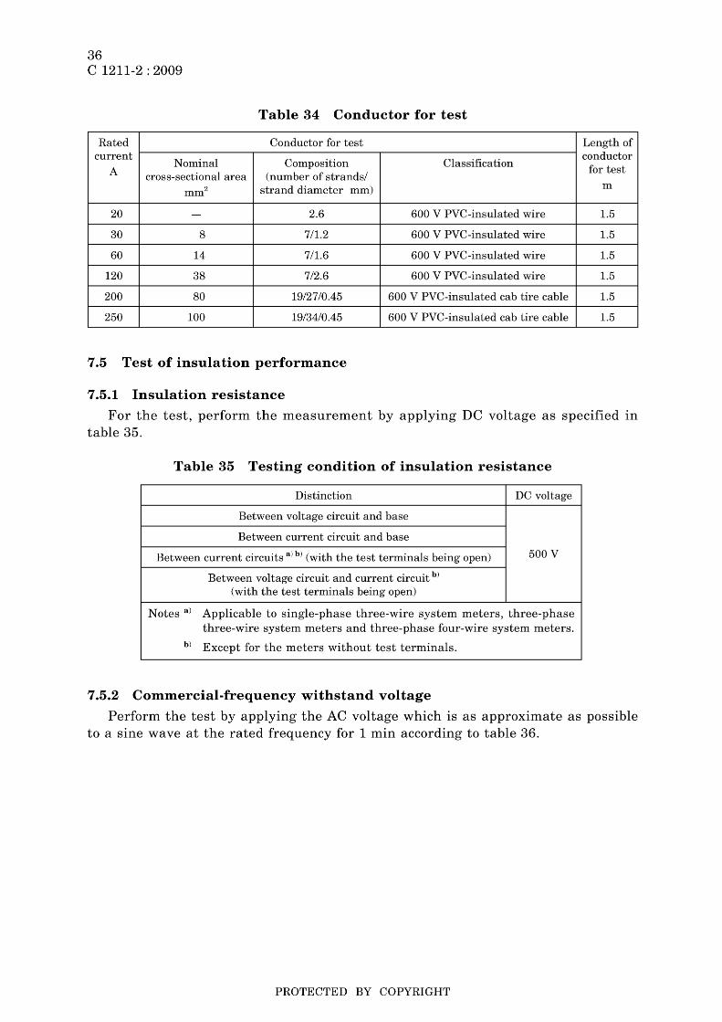
36 C 1211-2 : 2009
Table 34 Conductor for test
Rated Conductor for test Length of current
Nominal Composition Classifica tion conductor
A cross-sectional area (number of strandsl for test
mm2 strand diameter mm) m
20 - 2.6 600 V PVC-insulated wire 1.5
30 8 7/1.2 600 V PVC-insulated wire 1.5
60 14 7/1.6 600 V PVC-insulated wire 1.5
120 38 7/2.6 600 V PVC-insulated wire 1.5
200 80 19/27/0.45 600 V PVC-insulated cab tire cable 1.5
250 100 19/34/0.45 600 V PVC-insulated cab tire cable 1.5
7.5 Test of insulation performance
7.5.1 Insulation resistance
For the test, perform the measurement by applying DC voltage as specified in table 35.
Table 35 Testing condition of insulation resistance
Distinction DC voltage
Between voltage circuit and base
Between current circuit and base
Between current circuits alb) (with the test terminals being open) 500 V
Between voltage circuit and current circuit b)
(with the test terminals being open)
Notes a) Applicable to single-phase three-wire system meters, three-phase three-wire system meters and three-phase four-wire system meters.
b) Except for the meters without test terminals.
7.5.2 Commercial-frequency withstand voltage
Perform the test by applying the AC voltage which is as approximate as possible to a sine wave at the rated frequency for 1 min according to table 36.
PROTECTED BY COPYRIGHT
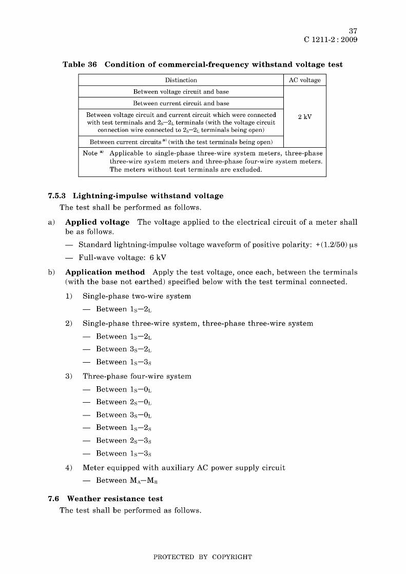
37 C 1211-2 : 2009
Table 36 Condition of commercial-frequency withstand voltage test
Distinction AC voltage
Between voltage circuit and base
Between current circuit and base
Between voltage circuit and current circuit which were connected 2 kV with test terminals and 2s-2L terminals (with the voltage circuit
connection wire connected to 2s-2L terminals being open)
Between current circuits a) (with the test terminals being open)
Note a) Applicable to single-phase three-wire system meters, three-phase three-wire system meters and three-phase four-wire system meters. The meters without test terminals are excluded.
7.5.3 Lightning-impulse withstand voltage
The test shall be performed as follows.
a) Applied voltage The voltage applied to the electrical circuit of a meter shall be as follows.
Standard lightning-impulse voltage waveform of positive polarity: + (1.2/50) ,"",S
Full-wave voltage: 6 kV
b) Application method Apply the test voltage, once each, between the terminals (with the base not earthed) specified below with the test terminal connected.
1) Single-phase two-wire system
- Between 18 -2L
2) Single-phase three-wire system, three-phase three-wire system
Between 18 -2L
Between 38 -2L
Between 18 -38
3) Three-phase four-wire system
Between 18 -OL
Between 28 -OL
Between 38 -OL
Between 18 -28
Between 28 -38
Between 18 -38
4) Meter equipped with auxiliary AC power supply circuit
- Between MA-MB
7.6 Weather resistance test
The test shall be performed as follows.
PROTECTED BY COPYRIGHT
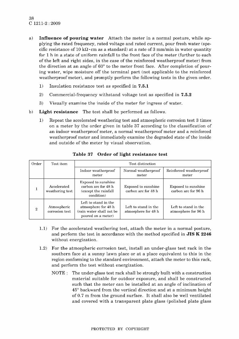
38 C 1211-2 : 2009
a) Influence of pouring water Attach the meter in a normal posture, while applying the rated frequency, rated voltage and rated current, pour fresh water (specific resistance of 10 kQ . cm as a standard) at a rate of 3 mm/min in water quantity for 1 h in a state of uniform rainfall to the front face of the meter (further to each of the left and right sides, in the case of the reinforced weatherproof meter) from the direction at an angle of 60° to the meter front face. After completion of pouring water, wipe moisture off the terminal part (not applicable to the reinforced weatherproof meter), and promptly perform the following tests in the given order.
1) Insulation resistance test as specified in 7.5.1
2) Commercial-frequency withstand voltage test as specified in 7.5.2
3) Visually examine the inside of the meter for ingress of water.
b) Light resistance The test shall be performed as follows.
1) Repeat the accelerated weathering test and atmospheric corrosion test 3 times on a meter by the order given in table 37 according to the classification of an indoor weatherproof meter, a normal weatherproof meter and a reinforced weatherproof meter and immediately examine the degraded state of the inside and outside of the meter by visual observation.
Table 37 Order of light resistance test
Order Test item Test distinction
1
2
Indoor weatherproof Normal weatherproof Reinforced weatherproof meter meter meter
Exposed to sunshine Accelerated carbon arc for 48 h Exposed to sunshine Exposed to sunshine
weathering test (except the rainfall carbon arc for 48 h carbon arc for 96 h condition)
Left to stand in the Atmospheric atmosphere for 48 h Left to stand in the Left to stand in the corrosion test (rain water shall not be atmosphere for 48 h atmosphere for 96 h
poured on a meter)
1.1) For the accelerated weathering test, attach the meter in a normal posture, and perform the test in accordance with the method specified in JIS K 2246 without energization.
1.2) For the atmospheric corrosion test, install an under-glass test rack in the southern face at a sunny lawn place or at a place equivalent to this in the region conforming to the standard environment, attach the meter to this rack, and perform the test without energization.
NOTE: The under-glass test rack shall be strongly built with a construction material suitable for outdoor exposure, and shall be constructed such that the meter can be installed at an angle of inclination of 45° backward from the vertical direction and at a minimum height of 0.7 m from the ground surface. It shall also be well ventilated and covered with a transparent plate glass (polished plate glass
PROTECTED BY COPYRIGHT
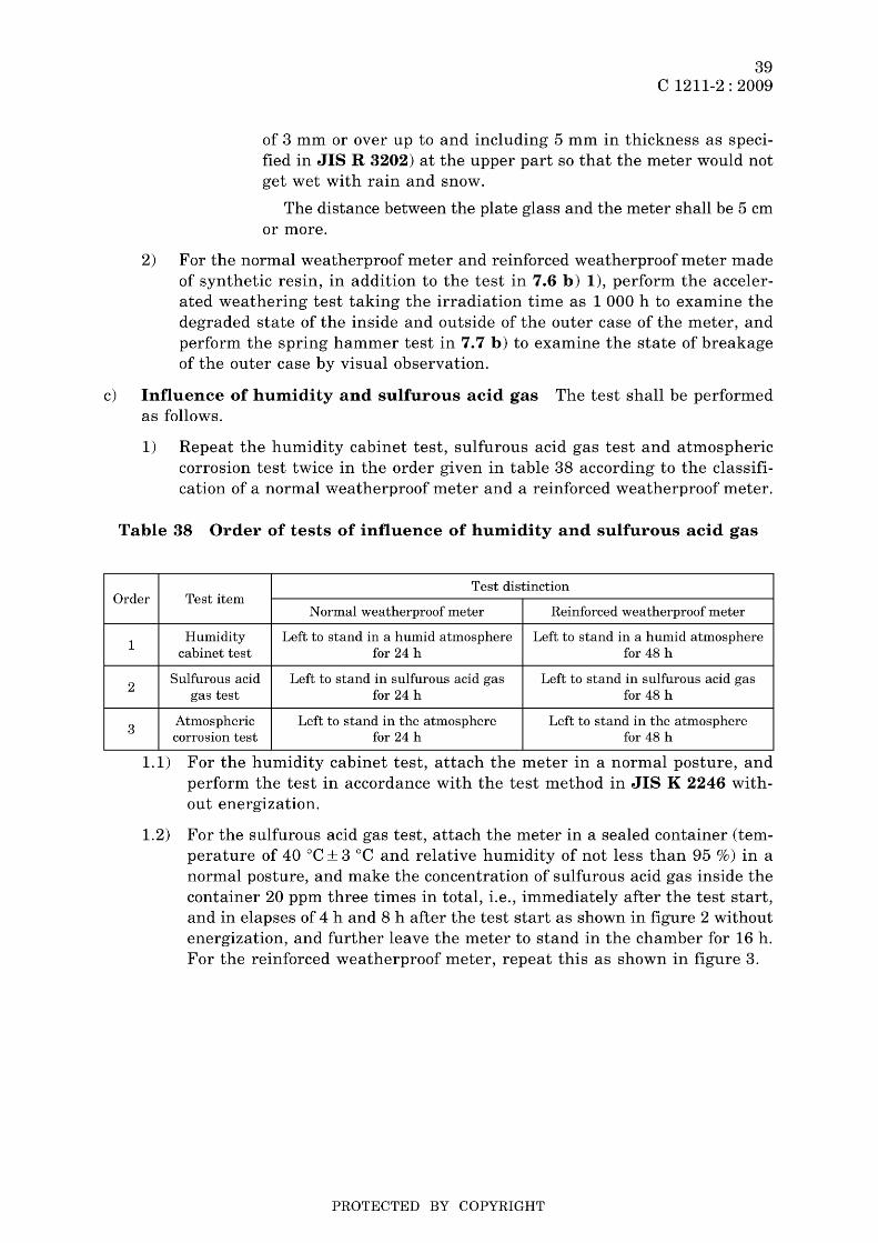
39 C 1211-2 : 2009
of 3 mm or over up to and including 5 mm in thickness as specified in JIS R 3202) at the upper part so that the meter would not get wet with rain and snow.
The distance between the plate glass and the meter shall be 5 cm or more.
2) For the normal weatherproof meter and reinforced weatherproof meter made of synthetic resin, in addition to the test in 7.6 b) 1), perform the accelerated weathering test taking the irradiation time as 1 000 h to examine the degraded state of the inside and outside of the outer case of the meter, and perform the spring hammer test in 7.7 b) to examine the state of breakage of the outer case by visual observation.
c) Influence of humidity and sulfurous acid gas The test shall be performed as follows.
1) Repeat the humidity cabinet test, sulfurous acid gas test and atmospheric corrosion test twice in the order given in table 38 according to the classification of a normal weatherproof meter and a reinforced weatherproof meter.
Table 38 Order of tests of influence of humidity and sulfurous acid gas
Test distinction Order Test item
1
2
3
Normal weatherproof meter Reinforced weatherproof meter
Humidity Left to stand in a humid atmosphere Left to stand in a humid atmosphere cabinet test for 24 h for 48 h
Sulfurous acid Left to stand in sulfurous acid gas Left to stand in sulfurous acid gas gas test for 24 h for 48 h
Atmospheric Left to stand in the atmosphere Left to stand in the atmosphere corrosion test for 24 h for 48 h
1.1) For the humidity cabinet test, attach the meter in a normal posture, and perform the test in accordance with the test method in JIS K 2246 without energization.
1.2) For the sulfurous acid gas test, attach the meter in a sealed container (temperature of 40°C ± 3 °C and relative humidity of not less than 95 %) in a normal posture, and make the concentration of sulfurous acid gas inside the container 20 ppm three times in total, i.e., immediately after the test start, and in elapses of 4 hand 8 h after the test start as shown in figure 2 without energization, and further leave the meter to stand in the chamber for 16 h. For the reinforced weatherproof meter, repeat this as shown in figure 3.
PROTECTED BY COPYRIGHT
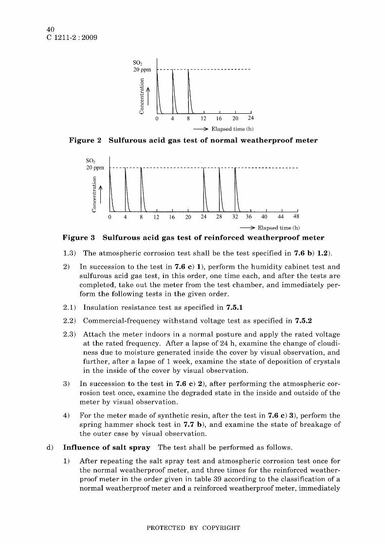
40 C 1211-2 : 2009
S02 20 ppm
~ o
11 ~ o o
o 4 8 12 16 20 24
--?- Elapsed time (h)
Figure 2 Sulfurous acid gas test of normal weatherproof meter
S02 20ppm -------- ---------------------- ---- ------------------
I I I \ I I I I
o 4 8 12 16 20 24 28 32 36 40 44 48
--?- Elapsed time (h)
Figure 3 Sulfurous acid gas test of reinforced weatherproof meter
1.3) The atmospheric corrosion test shall be the test specified in 7.6 b) 1.2).
2) In succession to the test in 7.6 c) 1), perform the humidity cabinet test and sulfurous acid gas test, in this order, one time each, and after the tests are completed, take out the meter from the test chamber, and immediately perform the following tests in the given order.
2.1) Insulation resistance test as specified in 7.5.1
2.2) Commercial-frequency withstand voltage test as specified in 7.5.2
2.3) Attach the meter indoors in a normal posture and apply the rated voltage at the rated frequency. After a lapse of 24 h, examine the change of cloudiness due to moisture generated inside the cover by visual observation, and further, after a lapse of 1 week, examine the state of deposition of crystals in the inside of the cover by visual observation.
3) In succession to the test in 7.6 c) 2), after performing the atmospheric corrosion test once, examine the degraded state in the inside and outside of the meter by visual observation.
4) For the meter made of synthetic resin, after the test in 7.6 c) 3), perform the spring hammer shock test in 7.7 b), and examine the state of breakage of the outer case by visual observation.
d) Influence of salt spray The test shall be performed as follows.
1) After repeating the salt spray test and atmospheric corrosion test once for the normal weatherproof meter, and three times for the reinforced weatherproof meter in the order given in table 39 according to the classification of a normal weatherproof meter and a reinforced weatherproof meter, immediately
PROTECTED BY COPYRIGHT

Order
1
2
41 C 1211-2 : 2009
examine the degraded state in the inside and outside of the meter by visual observation.
Table 39 Conditions for test of influence of salt spray
Test distinction Test item
Normal weatherproof meter Reinforced weatherproof meter
Salt spray test Sal t spray for 24 hours Salt spray for 48 hours
Atmospheric Left to stand in the atmosphere Left to stand in the atmosphere corrosion test for 24 h for 48 h
1.1) For the salt spray test, attach the meter in a normal posture, and perform the test in accordance with the test method in JIS Z 2371 without energization.
1.2) The atmospheric corrosion test shall be the test as specified in 7.6 b) 1.2).
2) For the meter made of synthetic resin, after the test in 7.6 d) 1), perform the spring hammer shock test in 7.7 b), and examine the state of breakage of the outer case by visual observation.
e) Influence of packing aging The test shall be performed as follows.
1) For the test of the influence of packing aging, after applying the temperature change to the meter in the order given in table 40 without energization, further perform the test in 7.6 a), and examine the state of packing aging by visual observation.
Table 40 Order of tests of influence of packing aging
Order Temperature Test time Condition °C h
1 70± 2 48 In circulation air
2 20± 15 3 -
3 -20± 2 10 Thermostatic oven
4 20± 15 3 -
2) For the meter made of synthetic resin, after the test in 7.6 e) 1), perform the spring hammer shock test in 7.7 b), and examine the state of breakage of the outer case by visual observation.
f) Influence of high temperature and rapid cooling Leave the meter to stand in a thermostatic oven maintained at a temperature of 50°C ± 2 °C for 1 h without energization, then take it out immediately and attach it in a normal posture. Pour fresh water of a temperature of 10°C ± 2 °C at a rate of 3 mm/min in water quantity for 1 min in a state of uniform rainfall to the meter from the direction at an angle of about 60° with respect to the front face of the meter, and examine the existence of abnormalities in the cover by visual observation. For the reinforced weatherproof meter, perform the test in the thermostatic oven with the rated current passed at the rated frequency and rated voltage.
PROTECTED BY COPYRIGHT
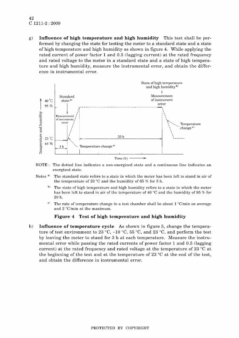
42 C 1211-2 : 2009
g) Influence of high temperature and high humidity This test shall be performed by changing the state for testing the meter to a standard state and a state of high temperature and high humidity as shown in figure 4. While applying the rated current of power factor 1 and 0.5 (lagging current) at the rated frequency and rated voltage to the meter in a standard state and a state of high temperature and high humidity, measure the instrumental error, and obtain the difference in instrumental error.
t 40 'c ~ I 95 % ,
Standard state a)
State of high temperature and high humidity b)
~ Measurement of instrument
r------------------------------------/ \ 1
error
Measurement / \ of instrument / \
error / ~ Temperature / \ change c)
I \ I \
I 20 h \
--~:-~ Temperature change oj ,-----
I Time (h) )I
NOTE: The dotted line indicates a non-energized state and a continuous line indicates an energized state.
Notes a) The standard state refers to a state in which the meter has been left to stand in air of the temperature of 23°C and the humidity of 65 % for 3 h.
b) The state of high temperature and high humidity refers to a state in which the meter has been left to stand in air of the temperature of 40°C and the humidity of 95 % for 20 h.
c) The rate of temperature change in a test chamber shall be about 1°C/min on average and 2 DC/min at the maximum.
Figure 4 Test of high temperature and high humidity
h) Influence of temperature cycle As shown in figure 5, change the temperature of test environment to 23°C, -10°C, 55°C, and 23 °C, and perform the test by leaving the meter to stand for 3 h at each temperature. Measure the instrumental error while passing the rated currents of power factor 1 and 0.5 (lagging current) at the rated frequency and rated voltage at the temperature of 23°C at the beginning of the test and at the temperature of 23 °C at the end of the test, and obtain the difference in instrumental error.
PROTECTED BY COPYRIGHT
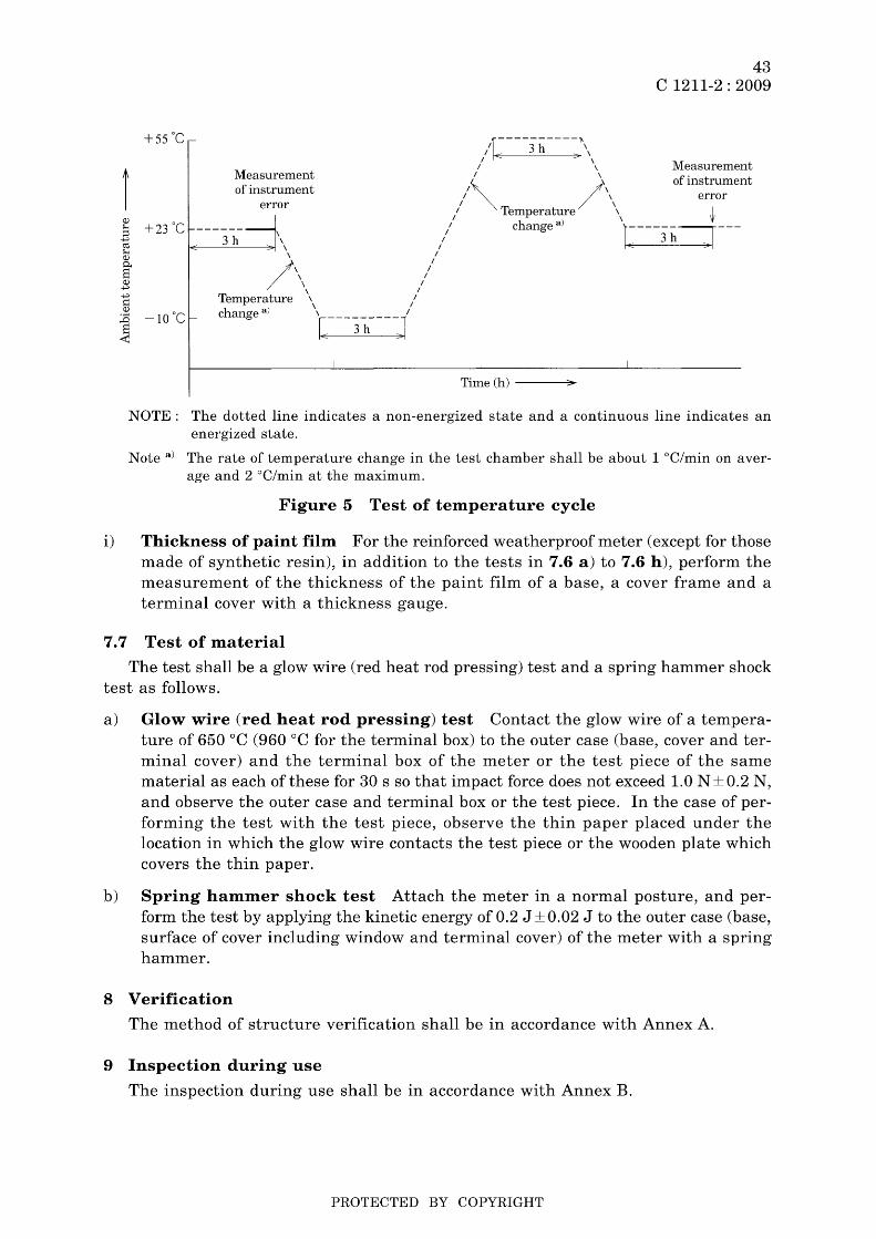
Measurement of instrument
error
3h , ,
~---~ , ,
/ ' / , I , I , I
Temperature \ /
change a) t---"3-h----J1
I
Ir----3h----J, / e::: :?' \
I ,
43 C 1211-2 : 2009
Measurement of instrument 1\ /',
I ~ , error / Temperature \ I
I )' IjI / change a r----3h--r---
I e::: ->1
Time (h) ~
NOTE: The dotted line indicates a non-energized state and a continuous line indicates an energized state.
Note a) The rate of temperature change in the test chamber shall be about 1 °C/min on average and 2 °C/min at the maximum.
Figure 5 Test of temperature cycle
i) Thickness of paint film For the reinforced weatherproof meter (except for those made of synthetic resin), in addition to the tests in 7.6 a) to 7.6 h), perform the measurement of the thickness of the paint film of a base, a cover frame and a terminal cover with a thickness gauge.
7.7 Test of material
The test shall be a glow wire (red heat rod pressing) test and a spring hammer shock test as follows.
a) Glow wire (red heat rod pressing) test Contact the glow wire of a temperature of 650°C (960°C for the terminal box) to the outer case (base, cover and terminal cover) and the terminal box of the meter or the test piece of the same material as each of these for 30 s so that impact force does not exceed 1.0 N ± 0.2 N, and observe the outer case and terminal box or the test piece. In the case of performing the test with the test piece, observe the thin paper placed under the location in which the glow wire contacts the test piece or the wooden plate which covers the thin paper.
b) Spring hammer shock test Attach the meter in a normal posture, and perform the test by applying the kinetic energy of 0.2 J ±0.02 J to the outer case (base, surface of cover including window and terminal cover) of the meter with a spring hammer.
8 Verification
The method of structure verification shall be in accordance with Annex A.
9 Inspection during use
The inspection during use shall be in accordance with Annex B.
PROTECTED BY COPYRIGHT
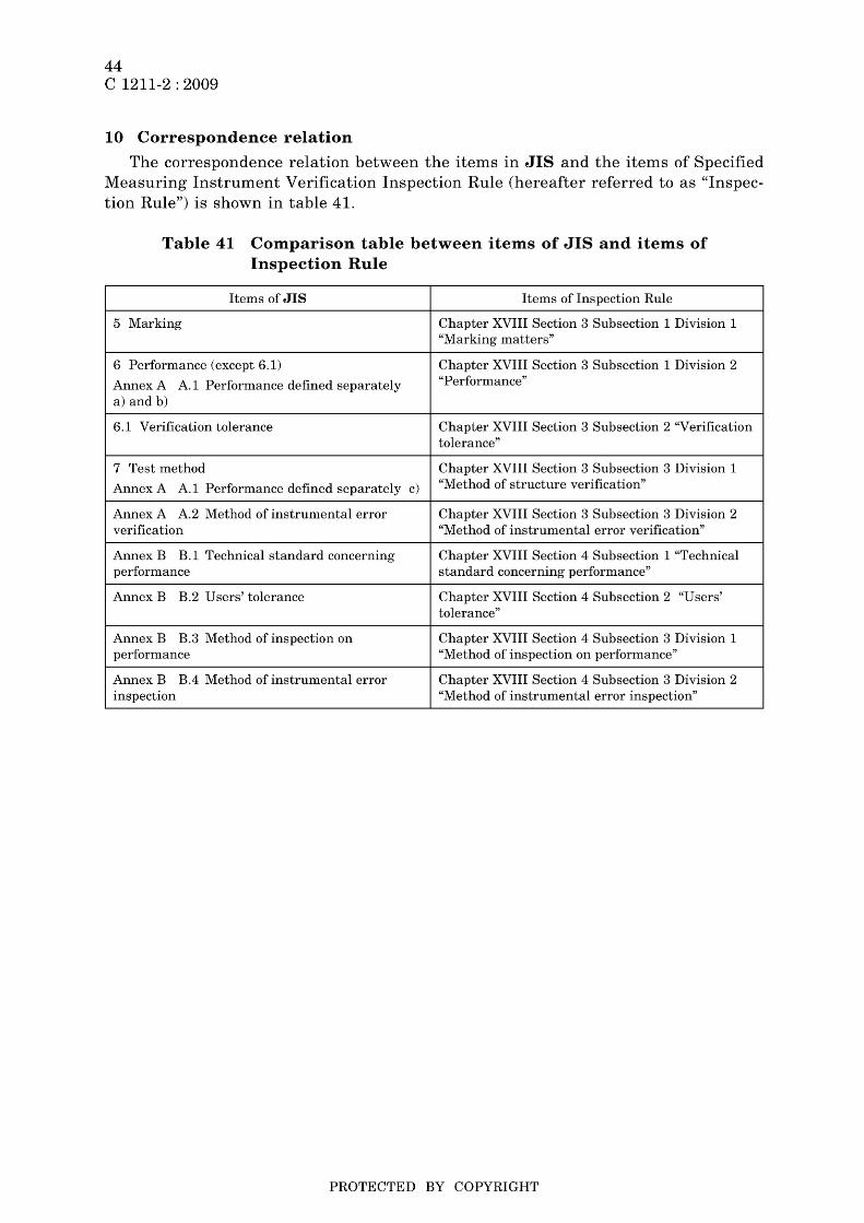
44 C 1211-2 : 2009
10 Correspondence relation
The correspondence relation between the items in JIS and the items of Specified Measuring Instrument Verification Inspection Rule (hereafter referred to as "Inspection Rule") is shown in table 41.
Table 41 Comparison table between items of JIS and items of Inspection Rule
Items of JIS Items of Inspection Rule
5 Marking Chapter XVIII Section 3 Subsection 1 Division 1 "Marking matters"
6 Performance (except 6.1) Chapter XVIII Section 3 Subsection 1 Division 2
AnnexA A.1 Performance defined separately "Performance"
a) and b)
6.1 Verification tolerance Chapter XVIII Section 3 Subsection 2 "Verification tolerance"
7 Test method Chapter XVIII Section 3 Subsection 3 Division 1
AnnexA A.1 Performance defined separately c) "Method of structure verification"
AnnexA A.2 Method of instrumental error Chapter XVIII Section 3 Subsection 3 Division 2 verification "Method of instrumental error verification"
Annex B B.1 Technical standard concerning Chapter XVIII Section 4 Subsection 1 "Technical performance standard concerning performance"
Annex B B.2 Users'tolerance Chapter XVIII Section 4 Subsection 2 "Users' tolerance"
Annex B B.3 Method of inspection on Chapter XVIII Section 4 Subsection 3 Division 1 performance "Method of inspection on performance"
Annex B B.4 Method of instrumental error Chapter XVIII Section 4 Subsection 3 Division 2 inspection "Method of instrumental error inspection"
PROTECTED BY COPYRIGHT

Annex A (normative)
Method of verification
A.l Performance defined separately
45 C 1211-2 : 2009
The performance defined separately and the test method shall be as follows.
a) The performance defined separately shall be in accordance with 6.2.1, 6.2.2,6.3.2, 6.3.7, 6.5.1 and 6.6 i).
b) The performance defined separately of a single-phase three-wire system meter shall be in accordance with the test method in A.l a), and 6.2.5.
c) The test method of the performance defined separately shall be in accordance with 7.2.1,7.2.2, 7.2.5, 7.3.2, 7.3.7,7.5.1 and 7.6 i). However, for the test of whether a single-phase three-wire system meter conforms to the specification in 6.2.5 which is applied as specified in A.l b), irrespective of the specification in 7.2.5, in the case where the load current corresponding to 50 % of the rated current of power factor 1 at the rated frequency and rated voltage is passed, the test may be performed by measuring the instrumental error in a state of balanced load and the instrumental error in a state of unbalanced load and calculating the difference between them. In this case, the calculated difference shall not exceed the limit of 2.5 %. Furthermore, for the test in 7.6 i), acceptance may be judged by visually confirming that the paint film thickness is equivalent or superior to that of the meter of which the paint film thickness of the outer case has been confirmed to be 30 ~m or more.
A.2 Method of instrumental error verification
The instrumental error verification of a watt-hour meter shall be performed as follows.
a) Perform the instrumental error verification of each watt-hour meter in accordance with 7.1.
b) For two or more watt-hour meters contained in a compound electric meter, the instrumental error inspection may be performed on anyone watt-hour meter from among the watt-hour meters of the greatest maximum electric power in accordance with 7.1, and for other watt-hour meters, the inspection may be performed on any one watt-hour meter selected from among them.
c) Perform the measurement of the instrumental error with the reference watt-hour meter stipulated in Article 4 of Inspection Rule of Verification Standards.
PROTECTED BY COPYRIGHT
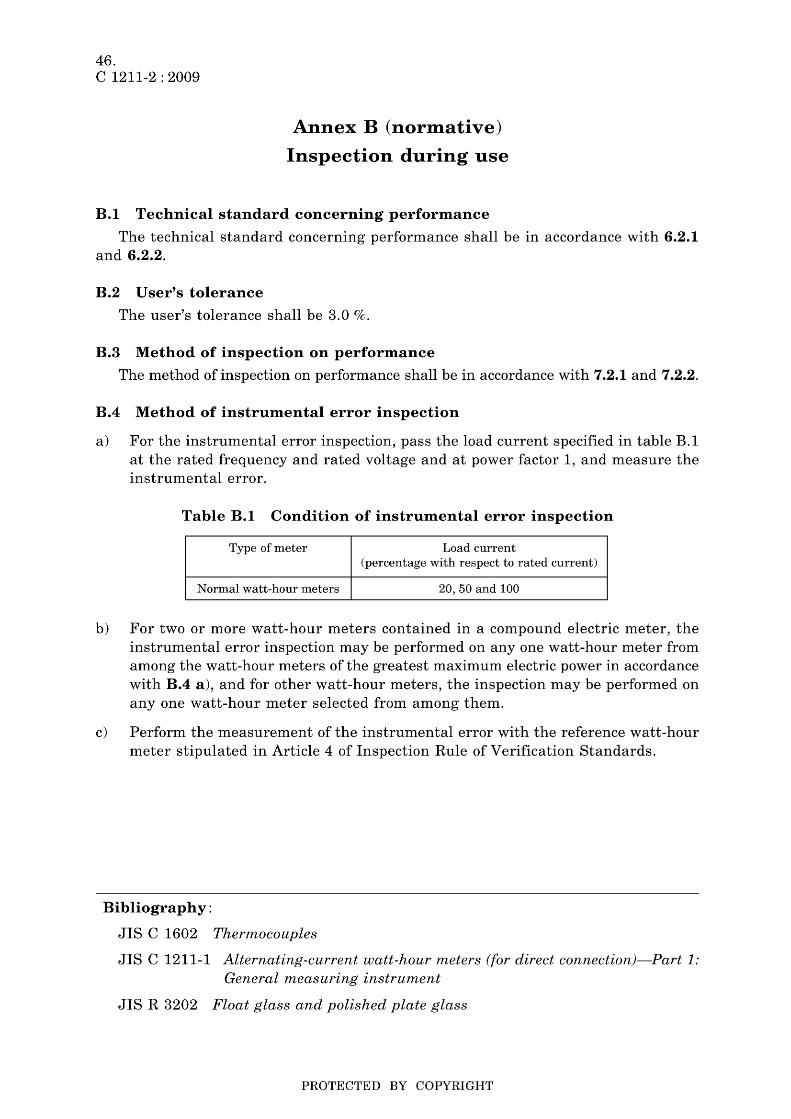
46. C 1211-2 : 2009
Annex B (normative)
Inspection during use
B.l Technical standard concerning performance
The technical standard concerning performance shall be in accordance with 6.2.1 and 6.2.2.
B.2 User's tolerance
The user's tolerance shall be 3.0 %.
B.3 Method of inspection on performance
The method of inspection on performance shall be in accordance with 7.2.1 and 7.2.2.
B.4 Method of instrumental error inspection
a) For the instrumental error inspection, pass the load current specified in table B.1 at the rated frequency and rated voltage and at power factor 1, and measure the instrumental error.
Table B.l Condition of instrumental error inspection
Type of meter Load current (percentage with respect to rated current)
Normal watt-hour meters 20,50 and 100
b) For two or more watt-hour meters contained in a compound electric meter, the instrumental error inspection may be performed on anyone watt-hour meter from among the watt-hour meters of the greatest maximum electric power in accordance with B.4 a), and for other watt-hour meters, the inspection may be performed on anyone watt-hour meter selected from among them.
c) Perform the measurement of the instrumental error with the reference watt-hour meter stipulated in Article 4 of Inspection Rule of Verification Standards.
Bibliography:
JIS C 1602 Thermocouples
JIS C 1211-1 Alternating-current watt-hour meters (for direct connection}-Part 1: General measuring instrument
JIS R 3202 Float glass and polished plate glass
PROTECTED BY COPYRIGHT

Errata for JIS (English edition) are printed in Standardization and Quality Control, published monthly by the Japanese Standards Association, and also provided to subscribers of JIS (English edition) in Monthly Information.
Errata will be provided upon request, please contact: Standards Publishing Department, Japanese Standards Association 4-1-24, Akasaka, Minato-ku, Tokyo, 107-8440 JAPAN TEL. 03-3583-8002 FAX. 03-3583-0462
PROTECTED BY COPYRIGHT