jeppiaar engineering...
TRANSCRIPT

JEPPIAAR ENGINEERING COLLEGE
Jeppiaar Nagar, Rajiv Gandhi Salai – 600 119
DEPARTMENT OF MECHANICAL ENGINEERING
QUESTION BANK
III SEMESTER
CE6451 – FLUID MECHANICS AND MACHINERY Regulation – 2013

JEPPIAAR ENGINEERING COLLEGE
Vision of Institution
To build Jeppiaar Engineering College as an institution of academic excellence in
technological and management education to become a world class university.
Mission of Institution
To excel in teaching and learning, research and innovation by promoting the
principles of scientific analysis and creative thinking.
To participate in the production, development and dissemination of knowledge and
interact with national and international communities.
To equip students with values, ethics and life skills needed to enrich their lives and
enable them to meaningfully contribute to the progress of society.
To prepare students for higher studies and lifelong learning, enrich them with the
practical and entrepreneurial skills necessary to excel as future professionals and
contribute to Nation’s economy.
PO1 Engineering knowledge: Apply the knowledge of mathematics, science, engineering fundamentals, and
an engineering specialization to the solution of complex engineering problems.
PO2 Problem analysis: Identify, formulate, review research literature, and analyze complex engineering
problems reaching substantiated conclusions using first principles of mathematics, natural sciences, and
engineering sciences.
PO3 Design/development of solutions: Design solutions for complex engineering problems and design
system components or processes that meet the specified needs with appropriate consideration for the
public health and safety, and the cultural, societal, and environmental considerations
PO4 Conduct investigations of complex problems: Use research-based knowledge and research methods
including design of experiments, analysis and interpretation of data, and synthesis of the information to
provide valid conclusions.
PO5 Modern tool usage: Create, select, and apply appropriate techniques, resources, and modern
engineering and IT tools including prediction and modeling to complex engineering activities with an
understanding of the limitations.
PO6 The engineer and society: Apply reasoning informed by the contextual knowledge to assess societal,
health, safety, legal and cultural issues and the consequent responsibilities relevant to the professional
engineering practice.
PO7 Environment and sustainability: Understand the impact of the professional engineering solutions in
societal and environmental contexts, and demonstrate the knowledge of, and need for sustainable
development.
PO8 Ethics: Apply ethical principles and commit to professional ethics and responsibilities and norms of the
engineering practice.
PO9 Individual and team work: Function effectively as an individual, and as a member or leader in diverse
teams, and in multidisciplinary settings.
PO10 Communication: Communicate effectively on complex engineering activities with the engineering
community and with society at large, such as, being able to comprehend and write effective reports and
design documentation, make effective presentations, and give and receive clear instructions.
PO11 Project management and finance: Demonstrate knowledge and understanding of the engineering and
management principles and apply these to one’s own work, as a member and leader in a team, to
manage projects and in multidisciplinary environments.
PO12 Life-long learning: Recognize the need for, and have the preparation and ability to engage in
independent and life-long learning in the broadest context of technological change.

JEPPIAAR ENGINEERING COLLEGE
DEPARTMENT OF MECHANICAL ENGINEERING
Vision of the Department
To create excellent professionals in the field of Mechanical Engineering and to uplift the quality of
technical education on par with the International Standards.
Department Mission
1. To reinforce the fundamentals of Science and Mathematics to Mechanical Engineering and
critically and relatively investigate complex mechanical systems and processes.
2. To engage in the production, expansion and practice of advanced engineering applications
through knowledge sharing activities by interacting with global communities and industries.
3. To equip students with engineering ethics, professional roles, corporate social
responsibility and life skills and apply them for the betterment of society.
4. To promote higher studies and lifelong learning and entrepreneurial skills and develop
excellent professionals for empowering nation’s economy.
PEO’s
1. To enrich the technical knowledge of design, manufacturing and management of mechanical
systems and develop creative and analytical thinking in research.
2. To relate, strengthen and develop the theoretical knowledge of the Mechanical Engineering
by exhibiting various concepts applied through diverse industrial exposures and experts’
guidance.
3. Facilitate the students to communicate effectively on complex social, professional and
engineering activities with strict adherence to ethical principles.
4. Create awareness for independent and life long learning and develop the ability to keep
abreast of modern trends and adopt them for personal technological growth of the
nation.
PSO’s
1. To understand the basic concept of various mechanical engineering field such as design,
manufacturing, thermal and industrial engineering.
2. To apply the knowledge in advanced mechanical system and processes by using design and
analysis techniques.
3. To develop student’s professional skills to meet the industry requirements and entrepreneurial
skills for improving nation’s economy stronger.

JEPPIAAR ENGINEERING COLLEGE
Jeppiaar Nagar, Rajiv Gandhi Salai – 600 119
DEPARTMENT OF MECHANICAL ENGINEERING
QUESTION BANK
SUBJECT : CE6451 – FLUID MECHANICA AND MACHINERY
YEAR /SEM: II /III
UNIT I FLUID PROPERTIES AND FLOW CHARACTERISTICS
Units and dimensions- Properties of fluids- mass density, specific weight, specific volume, specific
gravity, viscosity, compressibility, vapor pressure, surface tension and capillarity. Flow characteristics
– concept of control volume - application of continuity equation, energy equation and momentum
equation.
PART – A CO Mapping : C204.1
Q.No Questions BT Level
Competence PO
1 Define density or mass density. BTL-1 Remembering PO2,PO3
2 Define specific weight or weight density. BTL-1 Remembering PO1,PO4,PO12
3 Define specific volume. BTL-1 Remembering PO2,PO4
4 Define dynamic viscosity. BTL-1 Remembering PO2,PO3
5 Define Kinematic viscosity BTL-1 Remembering PO1,PO2
6 What are the types of fluids? BTL-1 Remembering PO1,PO2
7 Define Compressibility. BTL-1 Remembering PO1,PO3
8 Define Surface Tension. BTL-1 Remembering PO1,PO2
9 Expression for Surface tension on a liquid droplet. BTL-3 Applying PO1,PO2,PO3
10 Define Capillarity. BTL-1 Remembering PO1,PO3
11 Define Vapour Pressure. BTL-1 Understanding PO1,PO2,PO12
12 Define Control Volume. BTL-1 Remembering PO2,PO3
13 Write the continuity equation. [ BTL-1 Remembering PO1,PO3
14 List the types of fluid flow. BTL-4 Analyzing PO1,PO2
15 Define Steady and Unsteady flow. BTL-1 Remembering PO1,PO2,PO12
16 Define Uniform and Non-uniform flow. BTL-1 Remembering PO1,PO2
17 Compare Laminar and Turbulent flow. BTL-2 Understanding PO1,PO3,PO4
18 Define Compressible and incompressible flow BTL-1 Remembering PO1,PO2
19 Define Rotational and Ir-rotational flow. BTL-1 Remembering PO1,PO12
20 Define One, Two and Three dimensional flow. BTL-1 Remembering PO1,PO2
21 Write the Bernoulli’s equation applied between two
sections BTL-3 Applying PO1,PO2,PO12
22 State the assumptions used in deriving Bernoulli’s
equation BTL-1 Evaluating PO2,PO12

23 Write the Bernoulli’s equation applied between two
sections with losses. BTL-3 Applying PO1
24 List the instruments works on the basis of Bernoulli’s
equation. BTL-4 Analyzing PO1,PO12
25 Define Impulse Momentum Equation (or)
Momentum Equation. BTL-1 Remembering PO1,PO12
26 What is meant by continuum? BTL-1 Understanding PO1,PO8,PO11
27 What is the difference between guage pressure and
absolute pressure? BTL-1 Understanding PO2
28 Differentiate between solids and liquids. BTL-2 Understanding PO2
29 Define buoyancy. BTL-1 Remembering PO1
30 State Pascal’s law. BTL-1 Remembering PO1,PO3
31 Mention the uses of a manometer. BTL-2 Understanding PO1
32 What are Non-Newtonian fluids? Give examples. BTL-1 Remembering PO1,PO3
33 What is the variation of viscosity with temperature BTL-1 Remembering PO1
34 Find the height of a mountain where the atmospheric
pressure is 730mm of Hg at Normal conditions. BTL-5 Evaluating PO1,PO3
35 State Pascal’s hydrostatic law. BTL-1 Remembering PO1
PART – B & C
1
State Bernoulli’s theorem and assumptions for steady
flow of an incompressible fluid.
BTL-1 Remembering PO1,PO2,PO4
2
The space between two square flat parallel plate is
filled with oil. Each side of the plate is 600mm. The
thickness of the oil films is 12.5mm. The upper plate,
which moves at 2.5m /s, requires a force of 98.1 N to
maintain the speed. Determine
i.The dynamic viscosity of the oil in poise.
ii.The kinematic viscosity of the oil in strokes if the
specific gravity of the oil is 0.95.
BTL-5 Evaluating PO1,PO2,PO3,PO11
3
A U-tube is made of two capillaries of diameter 1mm
and 1.5mm respectively. The tube is kept vertically
and partially filled with water of surface tension
0.0736 N/m and zero contact angle. Calculate the
difference in the levels of the menisci caused by the
capillary.
BTL-5 Evaluating PO1,PO2.PO3,PO12
4
A pipe line 60cm in diameter bifurcates at a Y-
junction into two branches 40cm and 30cm in
diameter. If the rate of flow in the main pipe is
1.5m3/s and the mean velocity of flow in the 30cm
BTL-5 Evaluating PO1,PO2,PO4,PO11

pipe is 7.5m/s. Determine the rate of flow in the
40cm pipe.
5
Explain in detail the Newton’s law of viscosity.
Briefly classify the fluids based on the density and
viscosity. Give the limitations of applicability of
Newton’s law of viscosity.
BTL-2 Understanding PO1,PO2,PO4,PO12
6
Derive energy equations and state the assumptions
made while deriving the equations.
BTL-3 Applying PO1,PO3,PO11,PO12
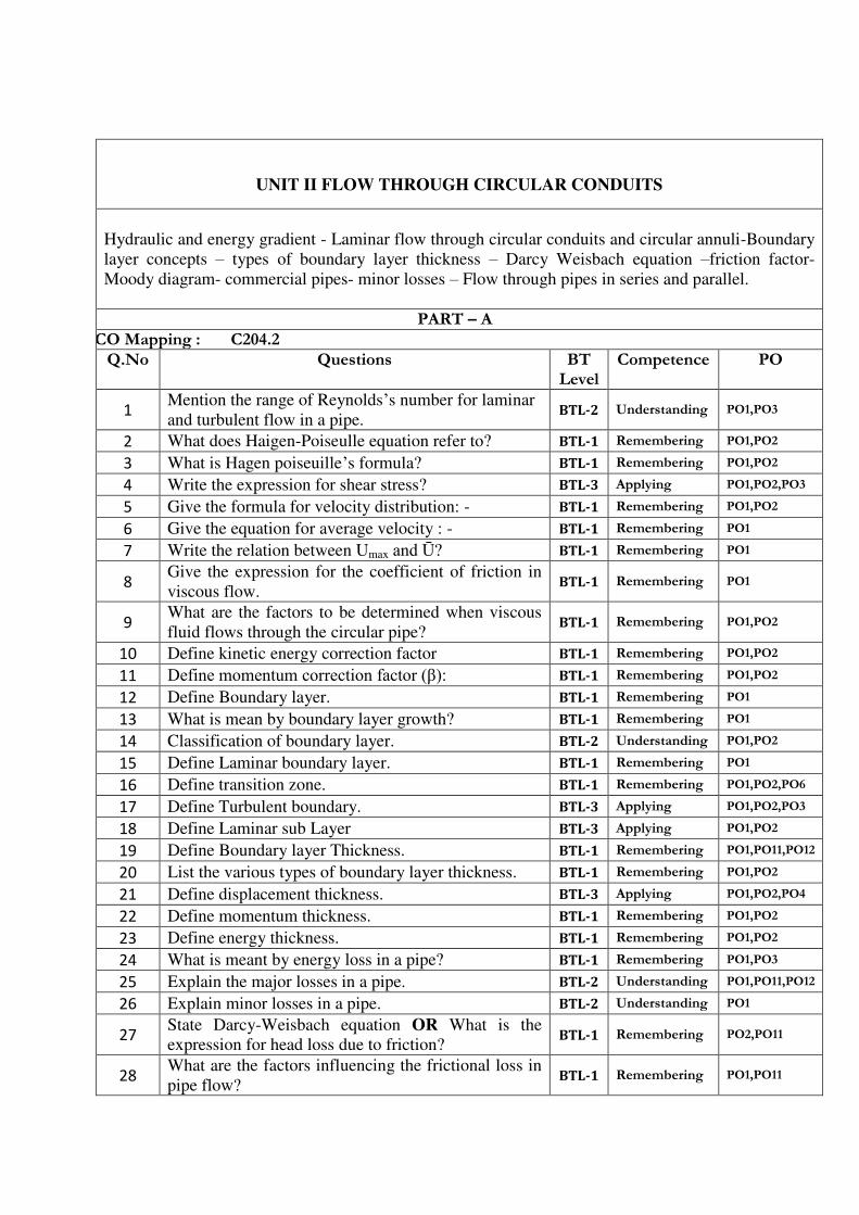
UNIT II FLOW THROUGH CIRCULAR CONDUITS
Hydraulic and energy gradient - Laminar flow through circular conduits and circular annuli-Boundary
layer concepts – types of boundary layer thickness – Darcy Weisbach equation –friction factor-
Moody diagram- commercial pipes- minor losses – Flow through pipes in series and parallel.
PART – A CO Mapping : C204.2
Q.No Questions BT Level
Competence PO
1 Mention the range of Reynolds’s number for laminar
and turbulent flow in a pipe. BTL-2 Understanding PO1,PO3
2 What does Haigen-Poiseulle equation refer to? BTL-1 Remembering PO1,PO2
3 What is Hagen poiseuille’s formula? BTL-1 Remembering PO1,PO2
4 Write the expression for shear stress? BTL-3 Applying PO1,PO2,PO3
5 Give the formula for velocity distribution: - BTL-1 Remembering PO1,PO2
6 Give the equation for average velocity : - BTL-1 Remembering PO1
7 Write the relation between Umax and Ū? BTL-1 Remembering PO1
8 Give the expression for the coefficient of friction in
viscous flow. BTL-1 Remembering PO1
9 What are the factors to be determined when viscous
fluid flows through the circular pipe? BTL-1 Remembering PO1,PO2
10 Define kinetic energy correction factor BTL-1 Remembering PO1,PO2
11 Define momentum correction factor ( ): BTL-1 Remembering PO1,PO2
12 Define Boundary layer. BTL-1 Remembering PO1
13 What is mean by boundary layer growth? BTL-1 Remembering PO1
14 Classification of boundary layer. BTL-2 Understanding PO1,PO2
15 Define Laminar boundary layer. BTL-1 Remembering PO1
16 Define transition zone. BTL-1 Remembering PO1,PO2,PO6
17 Define Turbulent boundary. BTL-3 Applying PO1,PO2,PO3
18 Define Laminar sub Layer BTL-3 Applying PO1,PO2
19 Define Boundary layer Thickness. BTL-1 Remembering PO1,PO11,PO12
20 List the various types of boundary layer thickness. BTL-1 Remembering PO1,PO2
21 Define displacement thickness. BTL-3 Applying PO1,PO2,PO4
22 Define momentum thickness. BTL-1 Remembering PO1,PO2
23 Define energy thickness. BTL-1 Remembering PO1,PO2
24 What is meant by energy loss in a pipe? BTL-1 Remembering PO1,PO3
25 Explain the major losses in a pipe. BTL-2 Understanding PO1,PO11,PO12
26 Explain minor losses in a pipe. BTL-2 Understanding PO1
27 State Darcy-Weisbach equation OR What is the
expression for head loss due to friction? BTL-1 Remembering PO2,PO11
28 What are the factors influencing the frictional loss in
pipe flow? BTL-1 Remembering PO1,PO11
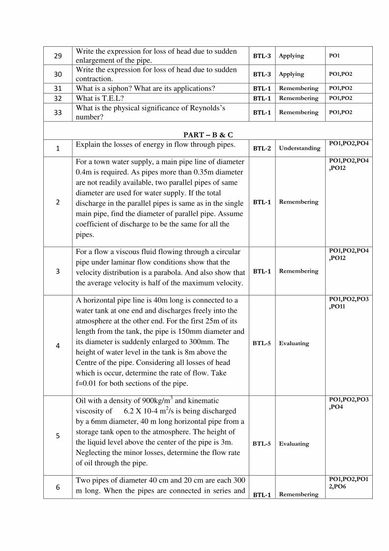
29 Write the expression for loss of head due to sudden
enlargement of the pipe. BTL-3 Applying PO1
30 Write the expression for loss of head due to sudden
contraction. BTL-3 Applying PO1,PO2
31 What is a siphon? What are its applications? BTL-1 Remembering PO1,PO2
32 What is T.E.L? BTL-1 Remembering PO1,PO2
33 What is the physical significance of Reynolds’s
number? BTL-1 Remembering PO1,PO2
PART – B & C
1 Explain the losses of energy in flow through pipes.
BTL-2 Understanding PO1,PO2,PO4
2
For a town water supply, a main pipe line of diameter
0.4m is required. As pipes more than 0.35m diameter
are not readily available, two parallel pipes of same
diameter are used for water supply. If the total
discharge in the parallel pipes is same as in the single
main pipe, find the diameter of parallel pipe. Assume
coefficient of discharge to be the same for all the
pipes.
BTL-1 Remembering
PO1,PO2,PO4,PO12
3
For a flow a viscous fluid flowing through a circular
pipe under laminar flow conditions show that the
velocity distribution is a parabola. And also show that
the average velocity is half of the maximum velocity.
BTL-1 Remembering
PO1,PO2,PO4,PO12
4
A horizontal pipe line is 40m long is connected to a
water tank at one end and discharges freely into the
atmosphere at the other end. For the first 25m of its
length from the tank, the pipe is 150mm diameter and
its diameter is suddenly enlarged to 300mm. The
height of water level in the tank is 8m above the
Centre of the pipe. Considering all losses of head
which is occur, determine the rate of flow. Take
f=0.01 for both sections of the pipe.
BTL-5
Evaluating
PO1,PO2,PO3,PO11
5
Oil with a density of 900kg/m3 and kinematic
viscosity of 6.2 X 10⁻⁴ m2/s is being discharged
by a 6mm diameter, 40 m long horizontal pipe from a
storage tank open to the atmosphere. The height of
the liquid level above the center of the pipe is 3m.
Neglecting the minor losses, determine the flow rate
of oil through the pipe.
BTL-5
Evaluating
PO1,PO2,PO3,PO4
6
Two pipes of diameter 40 cm and 20 cm are each 300
m long. When the pipes are connected in series and
BTL-1
Remembering
PO1,PO2,PO12,PO6

discharge through the pipe line is 0.10 m3/sec, find
the loss of head incurred. What would be the loss of
head in the system to pass the same total discharge
when the pipes are connected in parallel? Take f =
0.0075 for each pipe.

UNIT III DIMENSIONAL ANALYSIS
Need for dimensional analysis – methods of dimensional analysis – Similitude –types of similitude -
Dimensionless parameters- application of dimensionless parameters – Model analysis.
PART – A CO Mapping : C204.3
Q.No Questions BT Level
Competence PO
1 Define dimensional analysis. BTL-1 Remembering PO1,PO2
2 Write the uses of dimension analysis? BTL-3 Applying PO1,PO2
3 List the primary and derived quantities. BTL-1 Remembering PO1,PO2
4 What do you understand by fundamental units and
derived units? BTL-1 Remembering PO1,PO2
5 Define dimensional homogeneity. BTL-1 Remembering PO2,PO3
6 Mention the methods available for dimensional
analysis. BTL-2 Understanding PO1,PO3
7 State Buckingham’s π theorem. BTL-1 Remembering PO1,PO2,PO12
8 List the repeating variables used in Buckingham π theorem.
BTL-1 Remembering PO1,PO12
9 Define model and prototype. BTL-1 Remembering PO1,PO2
10 Write the advantages of model analysis. BTL-3 Applying PO1,PO2
11 List the types of similarities or similitude used in
model analysis. BTL-3 Applying PO1,PO2,PO3
12 Define geometric similarities BTL-1 Remembering PO1,PO6
13 Define kinematic similarities BTL-1 Remembering PO1,PO2
14 Define dynamic similarities BTL-1 Remembering PO1,PO2,PO3
15 Mention the various forces considered in fluid flow. BTL-2 Understanding PO1,PO2,PO3
16 Define model law or similarity law. BTL-1 Remembering PO1,PO2,PO12
17 List the various model laws applied in model
analysis. BTL-1 Remembering PO2,PO12
18 State Reynold’s model law
BTL-1 Remembering PO2,PO3
19 State Froude’s model law BTL-1 Remembering PO1,PO4
20 State Euler’s model law BTL-1 Remembering PO1,PO2,PO4
21 State Weber’s model law BTL-1 Remembering PO2,PO4
22 State Mach’s model law BTL-1 Remembering PO2,PO3,PO4
23 Classify the hydraulic models. BTL-2 Understanding PO1,PO2
24 Define undistorted model BTL-1 Remembering PO1,PO2
25 Define distorted model BTL-1 Remembering PO1,PO2
26 Define Scale effect BTL-2 Understanding PO2
27 List the advantages of distorted model. BTL-2 Understanding PO1
28 What are the uses of dimensional homogeneity? BTL-1 Remembering PO1,PO2,PO3
29 What are the points to be remembered while deriving
expressions using dimensional analysis? BTL-1 Remembering PO1,PO2
30 Define Mach number. BTL-1 Remembering PO1,PO2
31 State the methods of dimensional analysis. BTL-1 Remembering PO1,PO2

32 State the Euler model law and give its significance. BTL-1 Remembering PO1,PO2
PART – B & C
1
What are the significance and the role of the
following parameters?
i. Reynolds’s number
ii. Froude number
iii. Mach number
iv. Weber number
BTL-1 Remembering
PO1,PO2,PO12
2
The resisting force F of a plane during flight can be
considered as dependent upon the length of aircraft
(l), Velocity (v) air viscosity ( ), air density (ρ) and
bulk modulus of air (k). Express the functional
relationship between these variables using
dimensional analysis. Explain the physical
significance of the dimensionless groups arrived.
BTL-2 Understanding
PO1,PO3,PO12
3
The efficiency of a fan depends on density, viscosity
of the fluid, angular velocity, diameter of rotor and
discharge. Express in terms of NON-
DIMENSIONAL PARAMETERS. Using
Buckingham’s theorem.
BTL-2 Understanding
PO1,PO3,PO12
4
A geometrically similar model of an air duct is built
to 1/25 scale and tested with water which is 50 times
more viscous and 800 times denser than air. When
tested under dynamically similar conditions, the
pressure drop is 200 kN/m2 in the model. Find the
corresponding pressure drop in the full scale
prototype and express in cm of water.
BTL-1 Remembering
PO1,PO3,PO4
5
The power developed by hydraulic machines is found
to depend on the head h, flow rate Q, density ρ , speed N, runner diameter D, and acceleration due to
gravity g. Obtain suitable dimensionless parameters
to correlate experimental results.
BTL-4 Analyzing PO1,PO2,PO4
6
The capillary rise h is found to be influenced by the
tube diameter D, density ρ , gravitational acceleration g and surface tension σ . Determine the dimensionless parameters for the correlation of
experimental results.
BTL-5
Evaluating
PO1,PO2,PO4


UNIT IV PUMPS
Impact of jets - Euler’s equation - Theory of roto-dynamic machines – various efficiencies– velocity
components at entry and exit of the rotor- velocity triangles - Centrifugal pumps– working principle -
work done by the impeller - performance curves - Reciprocating pump- working principle – Rotary
pumps –classification.
PART – A CO Mapping : C204.4
Q.No Questions BT Level
Competence PO
1 What is meant by Pump? BTL-1 Remembering PO1,PO2,PO12
2 Mention main components of Centrifugal pump. BTL-2 Understanding PO1,PO2,PO12
3 What is meant by Priming? BTL-1 Remembering PO1,PO2
4 Define Manometric head.[ BTL-1 Remembering PO1,PO2
5 Define Mechanical efficiency. BTL-1 Remembering PO1,PO2
6 Define overall efficiency. BTL-1 Remembering PO1,PO3
7 Define speed ratio. BTL-1 Remembering PO1,PO3,PO4
8 Define flow ratio. BTL-1 Remembering PO1,PO2
9 Mention main components of Reciprocating pump. BTL-2 Understanding PO2,PO3,PO4
10 Define Slip of reciprocating pump. BTL-1 Remembering PO1,PO3,PO4
11 When the negative slip does occur? BTL-1 Remembering PO2,PO3
12 What is indicator diagram? BTL-1 Remembering PO2,PO3,PO4
13 What is meant by Cavitations? BTL-1 Remembering PO1,PO2
14 What are rotary pumps? BTL-1 Remembering PO1,PO2,PO4
15 What is meant by NPSH? BTL-1 Remembering PO1,PO2,PO3
16 List the losses in centrifugal pump BTL-1 Remembering PO1,PO2,PO4
17 Mention the working principle of an Air-vessel. BTL-2 Understanding PO1,PO2,PO3
18 Can actual discharge be greater than theoretical
discharge in a reciprocating pump? BTL-2 Understanding PO1,PO2
19 Which factor determines the maximum speed of a
reciprocating pump? BTL-1 Remembering PO1,PO2,PO3
20 What are the functions of an air vessel? BTL-3 Applying PO1,PO12
21 What is specific speed of a pump? How are pumps
classified based on this number? BTL-1 Remembering PO1,PO3
22 When will you select a reciprocating pump? BTL-1 Remembering PO1,PO11
23 What are Roto dynamic pumps? Give examples. BTL-1 Remembering PO1,PO3
24 Write short notes on types of rotary pumps. BTL-1 Remembering PO1,PO2,PO3,PO12
25 Derive an expression for the work saved in a
reciprocating pump by using air vessel. BTL-2 Understanding
PO1,PO2,PO3,PO11,PO12
26 Classify pumps on the basis of transfer of mechanical
energy. BTL-2 Understanding
PO1,PO2,PO3,PO11,PO12
27 Explain about the types of Gear pump. BTL-2 Understanding PO1,PO2,PO3,PO11,PO12

28 Draw a neat sketch of Vane pump. BTL-1 Remembering PO1,PO2,PO3,PO11,PO12
29 Draw a neat sketch of Lobe pump. BTL-1 Remembering PO1,PO2,PO3,PO11,PO12
30 Draw a neat sketch of Screw pump. BTL-1 Remembering PO1,PO2,PO3,PO11,PO12
31 Why the reciprocating pump is called a positive
displacement pump? BTL-1 Remembering
PO1,PO2,PO3,PO11,PO12
32 Brief an acceleration head. BTL-1 Remembering PO1,PO2,PO3,PO11,PO12
PART – B & C
1
Explain the working principle of single and double
acting reciprocating pumps, centrifugal pump with
neat diagram in detail. Also explain the effects of
inertia pressure and friction on the performance of
the pump using indicator diagrams with and without
air vessel.
BTL-2 Understanding
PO1,PO4,
2
Explain the working principle of screw pump, gear
pump, lobe pump, and vane pump. BTL-2 Understanding
PO1,PO2,PO3
3
A single acting reciprocatory pump has a plunger of
diameter 30cm and stroke of 20cm. If the speed of
the pumps is 30rpm and it delivers 6.5lit/s of water,
find the coefficient of discharge and the percentage
slip of the pump.
BTL-1 Remembering
PO1,PO3,PO4
4
Explain about indicator diagram & characteristic
curves of pumps with neat sketch. BTL-2 Understanding
PO1,PO2,PO3,PO4
5
A centrifugal pump with an impeller diameter of
0.4m runs at 1450rpm. The angle at outlet of the
backward curved vane is 25° with tangent. The flow
velocity remains constant at 3m/s. If the manometric
efficiency is 84%. Determine the fraction of the
kinetic energy at outlet recovered as static head.
BLT-5 Evaluating PO1,PO3,PO4
6
Explain the working principle of double acting
reciprocating pump. BTL-2 Understanding
PO1,PO2,PO4,PO6

UNIT V TURBINES
Classification of turbines – heads and efficiencies – velocity triangles. Axial, radial and mixed flow
turbines. Pelton wheel, Francis turbine and Kaplan turbines- working principles - work done by water
on the runner – draft tube. Specific speed - unit quantities – performance curves for turbines –
governing of turbines.
PART – A CO Mapping : C204.5
Q.No Questions BT Level
Competence PO
1 Define hydraulic machines. BTL-1 Remembering PO1,PO2,PO4
2 Give example for a low head, medium head and high
head turbine. BTL-2 Understanding PO1,PO2,PO3
3 What is impulse turbine? Give example. BTL-1 Remembering PO1,PO2
4 What is reaction turbine? Give example. BTL-1 Remembering PO1,PO2,PO3
5 What is axial flow turbine? BTL-1 Remembering PO1,PO2
6 What is mixed flow turbine? BTL-1 Remembering PO1,PO2
7 What is the function of spear and nozzle? BTL-1 Remembering PO1,PO2,PO3
8 Define gross head and net or effective head. BTL-1 Remembering PO1,PO2,PO12
9 Define hydraulic efficiency. BTL-1 Remembering PO1,PO2
10 Define mechanical efficiency. BTL-1 Remembering PO1,PO3
11 Define volumetric efficiency. BTL-1 Remembering PO1,PO4
12 Define over all efficiency. BTL-1 Evaluating PO1,PO12
13 State Euler turbine equation?[ BTL-1 Remembering PO1,PO2,PO3
14 Classify turbines according to head. BTL-2 Understanding PO1,PO2
15 Give example for a low head, medium head and high
head turbine. BTL-1 Remembering PO1,PO2,PO3
16 What are the functions of a draft tube? BTL-1 Remembering PO1,PO3
17 Differentiate between the turbines and pumps. BTL-4 Analyzing PO1,PO12
18 What are high head turbines? Give examples. BTL-1 Remembering PO1,PO12
19 What are the different types of draft tubes? BTL-1 Remembering PO1,PO2,PO11
20 What is the function of spear and nozzle? BTL-1 Remembering PO1,PO2
21 Draw velocity triangle diagram for Francis turbine.
BTL-1 Remembering PO1,PO2,PO12
22 Draw velocity triangle diagram for Kaplan turbine.
BTL-1 Remembering PO1,PO2,PO3
23 Classify turbines according to head. BTL-2 Understanding PO1,PO2,PO12
24 How do you classify turbines based on flow direction
and working medium. BTL-1 Remembering PO1,PO2,PO4
25 What is meant by governing of turbines? BTL-1 Remembering PO1,PO3,PO4
26 What is a draft tube? In which type of turbine it is
mostly used? BTL-1 Remembering PO1,PO2,PO3
27 Describe the application of turbine. BTL-2 Understanding PO1,PO2,PO4,

PO12
28 Define the specific speed of a turbine. BTL-1 Remembering PO1,PO2,PO4,PO12
29 Draw velocity triangle diagram for Pelton wheel
turbine. BTL-1 Remembering
PO1,PO2,PO4,PO12
30 List the types of dynamic analysis problems. BTL-1 Remembering PO1,PO2,PO3
31 State the principles on which turbo –machines are
based. BTL-1 Remembering
PO1,PO2,PO4,PO12
32 What is meant by inward radial flow turbine. BTL-4 Analyzing PO1,PO2,PO3
PART – B & C
1
A reaction turbine at 450 rpm, head 120 m, diameter
at inlet 120 cm, flow area 0.4 m2 has angles made by
absolute and relative velocities at inlet 20° and 60°
respectively. Find volume flow rate, H.P and
Efficiency.
BTL-1 Remembering
PO1,PO2,PO3,PO12
2
An inward flow reaction turbine having an overall
efficiency of 80% is required to deliver 136kw. The
head H is 16 m and the peripheral velocity is
3.3√ H . The radial velocity of flow at inlet is 1.1 √ H . The runner rotates at 120rpm. The hydraulic
losses in the turbine are 15% of the flow available
energy. Determine (i) diameter of the runner (ii)
guide vane angle (iii) the runner blade angle at inlet
(iv) the discharge through the turbine.
BLT-5 Evaluating PO1,PO2,PO3
3
A kaplan turbine delivers 10 MW under a head of
25m. The hub and tip diameters are 1.2m and 3m.
Hydraulic and overall efficiencies are 0.90 and 0.85.
If both velocity triangles are right angled triangles,
determine the speed, guide blade outlet angle and
blade outlet angle.
BLT-5 Evaluating PO1,PO2,PO12
4
Discuss characteristics curve, load efficiencies of
turbines.
BLT-6 Creating PO1,PO3,PO6
5 Explain the working principle of reaction turbine. BLT-2 Understanding PO1,PO2,PO4
6 Explain the working principle of impulse turbine. BLT-2 Understanding PO1,PO2,PO4

UNIT I FLUID PROPERTIES AND FLOW CHARACTERISTICS
Units and dimensions- Properties of fluids- mass density, specific weight, specific volume, specific gravity,
viscosity, compressibility, vapor pressure, surface tension and capillarity. Flow characteristics – concept of
control volume - application of continuity equation, energy equation and momentum equation.
PART-A 1. Define density or mass density. (May/June2013)
Density of a fluid is defined as the ratio of the mass of a fluid to its volume.
Density, ρ = mass/volume (Kg/m3
)
ρwater
= 1000 Kg/m3
2. Define specific weight or weight density. (May/June2013) Specific weight or weight density of a fluid is defined as the ratio between the weight of a fluid to its
volume.
Specific weight, = weight/volume (N/m3
)
= ρg
water = 9810 N/m
3
3. Define specific volume. (May/June 2012)
Specific volume of a fluid is defined as the volume of fluid occupied by an unit wt or unit mass of a fluid.
Specific volume vs = volume/ wt = 1/ = 1/ρg ----- for liquids Specific volume vs = volume/ mass = 1/ρ ----- for gases .
4. Define dynamic viscosity. (Nov/Dec 2010) Viscosity is defined as the property of fluid which offers resistance to the movement of one layer of fluid
over another adjacent layer of the fluid.
ζ = du
-----
dy
μ – dynamic viscosity or viscosity or coefficient of viscosity (N-s/m2
)
1 N-s/m2
= 1 Pa-s = 10 Poise
5. Define Kinematic viscosity. (Nov/Dec 2011,14)
It is defined as the ratio between the dynamic viscosity and density of fluid.
= /ρ (m2
/s)
1 m2
/s = 10000 Stokes (or) 1 stoke = 10-4
m2
/s
6. Types of fluids. (May/June2012) Ideal fluid, Real fluid, Newtonian fluid, Non-Newtonian fluid, Ideal Plastic fluid.
7. Define Compressibility. (May/June 2013) It is defined as the ratio of volumetric strain to compressive stress.
Compressibility, = (d Vol/ Vol) / dp (m2
/N)
8. Define Surface Tension. (May/June 2013) Surface tension is defined as the tensile force acting on the surface of the liquid in contact with a gas or on
the surface between two immiscible liquids such that the contact surface behaves like a membrane under
tension.
Surface Tension, σ = Force/Length (N/m) σ
water = 0.0725 N/m σ
Mercury = 0.52 N/m
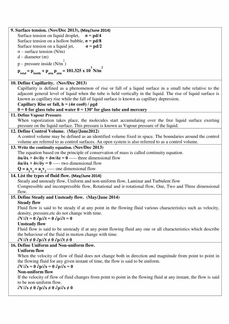
9. Surface tension. (Nov/Dec 2013), (May/June 2014)
Surface tension on liquid droplet, σ = pd/4 Surface tension on a hollow bubble, σ = pd/8 Surface tension on a liquid jet, σ = pd/2 σ – surface tension (N/m)
d – diameter (m)
p – pressure inside (N/m2
)
ptotal
= pinside
+ patm
patm
= 101.325 x 10³
N/m2
10. Define Capillarity. (Nov/Dec 2013) Capillarity is defined as a phenomenon of rise or fall of a liquid surface in a small tube relative to the
adjacent general level of liquid when the tube is held vertically in the liquid. The rise of liquid surface is
known as capillary rise while the fall of liquid surface is known as capillary depression.
Capillary Rise or fall, h = (4σ cosθ) / ρgd θ = 0 for glass tube and water θ = 130º for glass tube and mercury
11. Define Vapour Pressure.
When vaporization takes place, the molecules start accumulating over the free liquid surface exerting
pressure on the liquid surface. This pressure is known as Vapour pressure of the liquid.
12. Define Control Volume. (May/June2012) A control volume may be defined as an identified volume fixed in space. The boundaries around the control
volume are referred to as control surfaces. An open system is also referred to as a control volume.
13. Write the continuity equation. (Nov/Dec 2013)
The equation based on the principle of conservation of mass is called continuity equation.
δu/δx + δv/δy + δw/δz = 0 ----- three dimensional flow
δu/δx + δv/δy = 0 ----- two dimensional flow
Q = a1v
1 = a
2v
2 ----- one dimensional flow
14. List the types of fluid flow. (May/June 2014)
Steady and unsteady flow, Uniform and non-uniform flow, Laminar and Turbulent flow
Compressible and incompressible flow, Rotational and ir-rotational flow, One, Two and Three dimensional
flow.
15. Define Steady and Unsteady flow. (May/June 2014)
Steady flow Fluid flow is said to be steady if at any point in the flowing fluid various characteristics such as velocity,
density, pressure,etc do not change with time.
∂V/∂t = 0 ∂p/∂t = 0 ∂ρ/∂t = 0 Unsteady flow Fluid flow is said to be unsteady if at any point flowing fluid any one or all characteristics which describe
the behaviour of the fluid in motion change with time.
∂V/∂t ≠ 0 ∂p/∂t ≠ 0 ∂ρ/∂t ≠ 0 16. Define Uniform and Non-uniform flow.
Uniform flow When the velocity of flow of fluid does not change both in direction and magnitude from point to point in
the flowing fluid for any given instant of time, the flow is said to be uniform.
∂V/∂s = 0 ∂p/∂s = 0 ∂ρ/∂s = 0 Non-uniform flow If the velocity of flow of fluid changes from point to point in the flowing fluid at any instant, the flow is said
to be non-uniform flow.
∂V/∂s ≠ 0 ∂p/∂s ≠ 0 ∂ρ/∂s ≠ 0
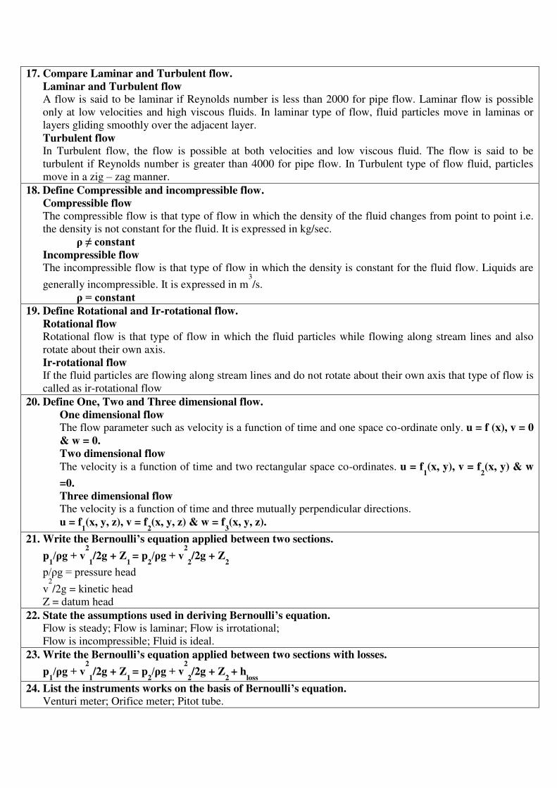
17. Compare Laminar and Turbulent flow.
Laminar and Turbulent flow A flow is said to be laminar if Reynolds number is less than 2000 for pipe flow. Laminar flow is possible
only at low velocities and high viscous fluids. In laminar type of flow, fluid particles move in laminas or
layers gliding smoothly over the adjacent layer.
Turbulent flow In Turbulent flow, the flow is possible at both velocities and low viscous fluid. The flow is said to be
turbulent if Reynolds number is greater than 4000 for pipe flow. In Turbulent type of flow fluid, particles
move in a zig – zag manner.
18. Define Compressible and incompressible flow.
Compressible flow The compressible flow is that type of flow in which the density of the fluid changes from point to point i.e.
the density is not constant for the fluid. It is expressed in kg/sec.
ρ ≠ constant Incompressible flow The incompressible flow is that type of flow in which the density is constant for the fluid flow. Liquids are
generally incompressible. It is expressed in m3
/s.
ρ = constant 19. Define Rotational and Ir-rotational flow.
Rotational flow Rotational flow is that type of flow in which the fluid particles while flowing along stream lines and also
rotate about their own axis.
Ir-rotational flow If the fluid particles are flowing along stream lines and do not rotate about their own axis that type of flow is
called as ir-rotational flow
20. Define One, Two and Three dimensional flow.
One dimensional flow The flow parameter such as velocity is a function of time and one space co-ordinate only. u = f (x), v = 0
& w = 0.
Two dimensional flow
The velocity is a function of time and two rectangular space co-ordinates. u = f1(x, y), v = f
2(x, y) & w
=0.
Three dimensional flow The velocity is a function of time and three mutually perpendicular directions.
u = f1(x, y, z), v = f
2(x, y, z) & w = f
3(x, y, z).
21. Write the Bernoulli’s equation applied between two sections.
p1/ρg + v
2
1/2g + Z
1 = p
2/ρg + v
2
2/2g + Z
2
p/ρg = pressure head v
2
/2g = kinetic head
Z = datum head
22. State the assumptions used in deriving Bernoulli’s equation. Flow is steady; Flow is laminar; Flow is irrotational;
Flow is incompressible; Fluid is ideal.
23. Write the Bernoulli’s equation applied between two sections with losses.
p1/ρg + v
2
1/2g + Z
1 = p
2/ρg + v
2
2/2g + Z
2 + h
loss
24. List the instruments works on the basis of Bernoulli’s equation. Venturi meter; Orifice meter; Pitot tube.

25. Define Impulse Momentum Equation (or) Momentum Equation. The total force acting on fluid is equal to rate of change of momentum. According to Newton’s second law
of motion, F = ma
F dt = d(mv)
26. Write the expression for loss of head at the entrance of the pipe.
hi =0.5V2
/2g hi = Loss of head at entrance of pipe. V = Velocity of liquid at inlet of the pipe.
27. Write the expression for loss of head at exit of the pipe.
ho = V2
/2g Where, ho = Loss of head at exit of the pipe.
V = Velocity of liquid at inlet and outlet of the pipe.
28. Give an expression for loss of head due to an obstruction in pipe. (May/June 2013)
Loss of head due to an obstruction = V2
/ 2g ( A/ Cc (A-a ) -1 )2
Where, A = area of pipe, a = Max area of obstruction,
V = Velocity of liquid in pipe A-a = Area of flow of liquid
29. What is compound pipe or pipes in series? When the pipes of different length and different diameters are connected end to end, then the pipes are called
as compound pipes or pipes in series.
30. What is mean by parallel pipe? and write the governing equations. ( Nov/Dec 2011) When the pipe divides into two or more branches and again join together downstream to form a single
pipe then it is called as pipes in parallel. The governing equations are:
Q1
= Q2
+ Q3 h
f1 = h
f2
PART-B
1. State Bernoulli’s theorem and assumptions for steady flow of an incompressible fluid. (May/June 2013)
Refer: “Dr.R.KBANSAL, “Fluid Mechanics and Machinery”, ”, Page No from 6 to 7 and from 10 to 11.
2. The space between two square flat parallel plate is filled with oil. Each side of the plate is 600mm. The
thickness of the oil films is 12.5mm. The upper plate, which moves at 2.5m /s, requires a force of 98.1 N to
maintain the speed. Determine
(i) The dynamic viscosity of the oil in poise.
(ii) The kinematic viscosity of the oil in strokes if the specific gravity of the oil is 0.95.
(May/June 2013)
Refer: “Dr.R.KBANSAL, “Fluid Mechanics and Machinery”, Page No from 6 to 7 and from 10 to 11.
3. A U-tube is made of two capillaries of diameter 1mm and 1.5mm respectively. The tube is kept
vertically and partially filled with water of surface tension 0.0736 N/m and zero contact angle. Calculate
the difference in the levels of the menisci caused by the capillary.
(May/June 2012)
Refer: “Dr.R.KBANSAL, “Fluid Mechanics and Machinery”, Page No from 6 to 7 and from 10 to 11.
4. A pipe line 60cm in diameter bifurcates at a Y-junction into two branches 40cm and 30cm in diameter.
If the rate of flow in the main pipe is 1.5m3/s and the mean velocity of flow in the 30cm pipe is 7.5m/s.
Determine the rate of flow in the 40cm pipe. (May/June 2012)
Refer: “Dr.R.KBANSAL, “Fluid Mechanics and Machinery”, ”, Page No from 6 to 7 and from 10 to 11
5. Explain in detail the Newton’s law of viscosity. Briefly classify the fluids based on the density and
viscosity. Give the limitations of applicability of Newton’s law of viscosity. (May/June 2014)
Refer: Dr.R.KBANSAL, Fluid Mechanics and Machinery , , Page No from 6 to 7 and from 10 to 11
6. Derive energy equations and state the assumptions made while deriving the equations.May/June 2014)

Refer: “Dr.R.KBANSAL, “Fluid Mechanics and Machinery”, ”, Page No from 6 to 7 and from 10 to 11
UNIT II FLOW THROUGH CIRCULAR CONDUITS
Hydraulic and energy gradient - Laminar flow through circular conduits and circular annuli-Boundary layer
concepts – types of boundary layer thickness – Darcy Weisbach equation –friction factor- Moody diagram-
commercial pipes- minor losses – Flow through pipes in series and parallel.
PART-A 1. Mention the range of Reynold’s number for laminar and turbulent flow in a pipe. (May/June 2014)
If the Reynold’s number is less than 2000, the flow is laminar. But if the Reynold’s number is greater than
4000, the flow is turbulent flow.
2. What does Haigen-Poiseulle equation refer to? (Nov/Dec 2011)
The equation refers to the value of loss of head in a pipe of length ‘L’ due to viscosity in a laminar flow.
3. What is Hagen poiseuille’s formula? (May/June 2012)
(P1-P
2) / ρg = h
f = 32 ŪL / ρgD
2
The expression is known as Hagen poiseuille formula.
Where P1-P
2 / ρg = Loss of pressure head, Ū= Average velocity,
μ = Coefficient of viscosity, D = Diameter of pipe, L = Length of pipe
4. Write the expression for shear stress? (Nov/Dec 2012)
Shear stress ζ = - (∂p/∂x) (r/2) ζmax = - (∂p/∂x) (R/2)
5. Give the formula for velocity distribution: - (Nov/Dec 2012) The formula for velocity distribution is given as
u = - (¼ ) (∂p/∂x) (R2
-r2
) Where R = Radius of the pipe, r = Radius of the fluid element
6. Give the equation for average velocity : - (May/June 2013) The equation for average velocity is given as
Ū = - (1/8 ) (∂p/∂x) R2
Where R = Radius of the pipe
7. Write the relation between Umax and Ū? (May/June 2013)
Umax / Ū = { - (¼ ) (∂p/∂x) R2
} / { - ⅛ (∂p/∂x) R2
}
Umax / Ū = 2 8. Give the expression for the coefficient of friction in viscous flow? (Nov/Dec 2013)
Coefficient of friction between pipe and fluid in viscous flow f =16/ Re
Where, f = Re = Reynolds number
9. What are the factors to be determined when viscous fluid flows through the circular pipe? (Nov/Dec
2013)
The factors to be determined are:
i. Velocity distribution across the section.
ii. Ratio of maximum velocity to the average velocity.
iii. Shear stress distribution.
iv. Drop of pressure for a given length.
10. Define kinetic energy correction factor. Kinetic energy factor is defined as the ratio of the kinetic energy of the flow per sec based on actual

velocity across a section to the kinetic energy of the flow per sec based on average velocity across the
same section. It is denoted by (α). K. E factor (α) = K.E per sec based on actual velocity / K.E per sec based on Average velocity
11. Define momentum correction factor ( ): It is defined as the ratio of momentum of the flow per sec based on actual velocity to the momentum of
the flow per sec based on average velocity across the section.
= Momentum per sec based on actual velocity/Momentum Per sec based on average velocity 12. Define Boundary layer.
When a real fluid flow passed a solid boundary, fluid layer is adhered to the solid boundary. Due to
adhesion fluid undergoes retardation thereby developing a small region in the immediate vicinity of the
boundary. This region is known as boundary layer.
13. What is mean by boundary layer growth?
At subsequent points downstream of the leading edge, the boundary layer region increases because the
retarded fluid is further retarded. This is referred as growth of boundary layer.
14. Classification of boundary layer. (i) Laminar boundary layer, (ii) Transition zone, (iii) Turbulent boundary layer.
15. Define Laminar boundary layer. Near the leading edge of the surface of the plate the thickness of boundary layer is small and flow is laminar.
This layer of fluid is said to be laminar boundary layer.
The length of the plate from the leading edge, upto which laminar boundary layer exists is called as laminar
zone. In this zone the velocity profile is parabolic.
16. Define transition zone.
After laminar zone, the laminar boundary layer becomes unstable and the fluid motion transformed to
turbulent boundary layer. This short length over which the changes taking place is called as transition zone.
17. Define Turbulent boundary. Further downstream of transition zone, the boundary layer is turbulent and continuous to grow in thickness.
This layer of boundary is called turbulent boundary layer. .
18. Define Laminar sub Layer. (May/June 2013)
In the turbulent boundary layer zone, adjacent to the solid surface of the plate the velocity variation is
influenced by viscous effects. Due to very small thickness, the velocity distribution is almost linear. This region
is known as laminar sub layer.
19. Define Boundary layer Thickness. It is defined as the distance from the solid boundary measured in y-direction to the point, where the velocity
of fluid is approximately equal to 0.99 times the free stream velocity (U) of the fluid. It is denoted by δ. 20. List the various types of boundary layer thickness.
Displacement thickness(δ*), Momentum thickness(θ), Energy thickness(δ**) 21. Define displacement thickness. The displacement thickness (δ) is defined as the distance by which the boundary should be displaced to
compensate for the reduction in flow rate on account of boundary layer formation.
δ* = ∫ [ 1 – (u/U) ] dy
22. Define momentum thickness. (May/June 2013)
The momentum thickness (θ) is defined as the distance by which the boundary should be displaced to compensate for the reduction in momentum of the flowing fluid on account of boundary layer formation.
θ = ∫ [ (u/U) – (u/U)2
] dy
23. Define energy thickness. The energy thickness (δ**) is defined as the distance by which the boundary should be displaced to compensate for the reduction in kinetic energy of the flowing fluid on account of boundary layer formation.

δ** = ∫ [ (u/U) – (u/U)3
] dy
24. What is meant by energy loss in a pipe? When the fluid flows through a pipe, it looses some energy or head due to frictional resistance and other
reasons. It is called energy loss. The losses are classified as; Major losses and Minor losses.
25. Explain the major losses in a pipe. The major energy losses in a pipe is mainly due to the frictional resistance caused by the shear force between
the fluid particles and boundary walls of the pipe and also due to viscosity of the fluid.
26. Explain minor losses in a pipe. The loss of energy or head due to change of velocity of the flowing fluid in magnitude or direction is called
minor losses. It includes: sudden expansion of the pipe, sudden contraction of the pipe, bend in a pipe, pipe
fittings and obstruction in the pipe, etc.
27. State Darcy-Weisbach equation OR What is the expression for head loss due to friction?
hf = 4flv
2
/ 2gd
where, hf = Head loss due to friction (m), L = Length of the pipe (m),
d = Diameter of the pipe (m), V = Velocity of flow (m/sec)
f = Coefficient of friction
28. What are the factors influencing the frictional loss in pipe flow? Frictional resistance for the turbulent flow is,
i. Proportional to vn
where v varies from 1.5 to 2.0.
ii. Proportional to the density of fluid.
iii. Proportional to the area of surface in contact.
iv. Independent of pressure.
v. Depend on the nature of the surface in contact.
29. Write the expression for loss of head due to sudden enlargement of the pipe.
hexp
= (V1-V
2)2
/2g
Where, hexp
= Loss of head due to sudden enlargement of pipe.
V1
= Velocity of flow at pipe 1; V2
= Velocity of flow at pipe 2.
30. Write the expression for loss of head due to sudden contraction. (May/June 2012)
hcon
=0.5 V2
/2g
hcon
= Loss of head due to sudden contraction. V = Velocity at outlet of pipe.
PART-B& PART-C 1. Explain the losses of energy in flow through pipes.
Refer: ““Dr.R.KBANSAL, “Fluid Mechanics and Machinery”, ”, Page No from 6 to 7 and from 10 to 11. 2. For a town water supply, a main pipe line of diameter 0.4m is required. As pipes more than 0.35m
diameter are not readily available, two parallel pipes of same diameter are used for water supply. If the
total discharge in the parallel pipes is same as in the single main pipe, find the diameter of parallel pipe.
Assume coefficient of discharge to be the same for all the pipes.
Refer: ““Dr.R.KBANSAL, “Fluid Mechanics and Machinery”, ”, Page No from 6 to 7 and from 10 to 11. 3. For a flow a viscous fluid flowing through a circular pipe under laminar flow conditions show that the
velocity distribution is a parabola. And also show that the average velocity is half of the maximum
velocity. (May/June 2012)
Refer: ““Dr.R.KBANSAL, “Fluid Mechanics and Machinery”, ”, Page No from 6 to 7 and from 10 to 11. 4. A horizontal pipe line is 40m long is connected to a water tank at one end and discharges freely into the
atmosphere at the other end. For the first 25m of its length from the tank, the pipe is 150mm diameter
and its diameter is suddenly enlarged to 300mm. The height of water level in the tank is 8m above the

Centre of the pipe. Considering all losses of head which is occur, determine the rate of flow. Take f=0.01
for both sections of the pipe. (May/June 2012)
Refer: ““Dr.R.KBANSAL, “Fluid Mechanics and Machinery”, ”, Page No from 6 to 7 and from 10 to 11. 5. Oil with a density of 900kg/m3 and kinematic viscosity of 6.2 X 10⁻⁴ m2/s is being discharged by a
6mm diameter, 40 m long horizontal pipe from a storage tank open to the atmosphere. The height of the
liquid level above the center of the pipe is 3m. Neglecting the minor losses, determine the flow rate of oil
through the pipe. (Nov/Dec 2012)
Refer: ““Dr.R.KBANSAL, “Fluid Mechanics and Machinery”, ”, Page No from 6 to 7 and from 10 to 11. 6. Two pipes of diameter 40 cm and 20 cm are each 300 m long. When the pipes are connected in series
and discharge through the pipe line is 0.10 m3/sec, find the loss of head incurred. What would be the loss
of head in the system to pass the same total discharge when the pipes are connected in parallel? Take f =
0.0075 for each pipe. (Nov/Dec 2012)
Refer: ““Dr.R.KBANSAL, “Fluid Mechanics and Machinery”, ”, Page No from 6 to 7 and from 10 to 11.
UNIT III DIMENSIONAL ANALYSIS
Need for dimensional analysis – methods of dimensional analysis – Similitude –types of similitude - Dimensionless
parameters- application of dimensionless parameters – Model analysis.
PART-A 1. Define dimensional analysis. (Nov/Dec 2013)
Dimensional analysis is a mathematical technique which makes use of the study of dimensions as an aid to solution
of several engineering problems. It plays an important role in research work.
2. Write the uses of dimension analysis. (May/June 2012)
• It helps in testing the dimensional homogeneity of any equation of fluid motion. • It helps in deriving equations expressed in terms of non-dimensional parameters.
• It helps in planning model tests and presenting experimental results in a systematic manner.
3. List the primary and derived quantities. (May/June 2012) Primary or Fundamental quantities: The various physical quantities used to describe a given phenomenon can
be described by a set of quantities which are independent of each other. These quantities are known as
fundamental quantities or primary quantities. Mass (M), Length (L), Time (T) and Temperature (θ) are the fundamental quantities.
Secondary or Derived quantities: All other quantities such as area, volume, velocity, acceleration, energy,
power, etc are termed as derived quantities or secondary quantities because they can be expressed by primary
quantities.
4. Write the dimensions for the followings. (May/June 2012)
Dynamic viscosity (μ) – ML-1
T-2
, Force (F) - MLT-2
,
Mass density (ρ) – ML-3
, Power (P) -ML2
T-3
5. Define dimensional homogeneity. (Nov/Dec2012) An equation is said to be dimensionally homogeneous if the dimensions of the terms on its LHS are same as the
dimensions of the terms on its RHS.
6. Mention the methods available for dimensional analysis. (Nov/Dec2012) Rayleigh method, Buckinghum π method
7. State Buckingham’s π theorem. May/June 2013) It states that “if there are ‘n’ variables (both independent & dependent variables) in a physical phenomenon and if
these variables contain ‘m’ functional dimensions and are related by a dimensionally homogeneous equation, and then
the variables are arranged into n-m dimensionless terms. Each term is called π term”.
8. List the repeating variables used in Buckingham π theorem. (May/June 2013)
Geometrical Properties – l, d, H, h, etc,
Flow Properties – v, a, g, ω, Q, etc, Fluid Properties – ρ, μ, , etc.
9. Define model and prototype. The small scale replica of an actual structure or the machine is known as its Model, while the actual structure or
machine is called as its Prototype. Mostly models are much smaller than the corresponding prototype.
10. Write the advantages of model analysis. • Model test are quite economical and convenient. • Alterations can be continued until most suitable design is obtained. • Modification of prototype based on the model results. • The information about the performance of prototype can be obtained well in advance.
11. List the types of similarities or similitude used in model analysis.
Geometric similarities, Kinematic similarities, Dynamic similarities
12. Define geometric similarities. It exists between the model and prototype if the ratio of corresponding lengths, dimensions in the model and the
prototype are equal. Such a ratio is known as “Scale Ratio”.
13. Define kinematic similarities. (May/June 2012)
It exists between the model and prototype if the paths of the homogeneous moving particles are geometrically
similar and if the ratio of the flow properties is equal.
14. Define dynamic similarities. It exits between model and the prototype which are geometrically and kinematically similar and if the ratio of all
forces acting on the model and prototype are equal.
15. Mention the various forces considered in fluid flow. Inertia force, Viscous force, Gravity force,
Pressure force, Surface Tension force, Elasticity force
16. Define model law or similarity law. The condition for existence of completely dynamic similarity between a model and its prototype are denoted by
equation obtained from dimensionless numbers. The laws on which the models are designed for dynamic similarity
are called Model laws or Laws of Similarity.
17. List the various model laws applied in model analysis. Reynold’s Model Law, Froude’s Model Law,
Euler’s Model Law, Weber Model Law, Mach Model Law
18. State Reynold’s model law. For the flow, where in addition to inertia force the viscous force is the only other predominant force, the
similarity of flow in the model and its prototype can be established, if the Renold’s number is same for both
the systems. This is known as Reynold’s model law. Re(p)
= Re(m)
19. State Froude’s model law.
When the forces of gravity can be considered to be the only predominant force which controls the motion in
addition to the force of inertia, the dynamic similarities of the flow in any two such systems can be established,
if the Froude number for both the system is the same. This is known as Froude Model Law. Fr(p)
= Fr (m)
20. State Euler’s model law. (May/June 2014) In a fluid system where supplied pressures are the controlling forces in addition to inertia forces and other forces
are either entirely absent or in-significant the Euler’s number for both the model and prototype which known as Euler
Model Law.
21. State Weber’s model law. When surface tension effect predominates in addition to inertia force then the dynamic similarity is obtained by

equating the Weber’s number for both model and its prototype, which is called as Weber Model Law.
22. State Mach’s model law. If in any phenomenon only the forces resulting from elastic compression are significant in addition to inertia
forces and all other forces may be neglected, then the dynamic similarity between model and its prototype may be
achieved by equating the Mach’s number for both the systems. This is known Mach Model Law.
23. Classify the hydraulic models. The hydraulic models are classified as: Undistorted model & Distorted model
24. Define undistorted model. An undistorted model is that which is geometrically similar to its prototype, i.e. the scale ratio for corresponding
linear dimensions of the model and its prototype are same.
25. Define distorted model. Distorted models are those in which one or more terms of the model are not identical with their counterparts in the
prototype.
26. Define Scale effect. An effect in fluid flow that results from changing the scale, but not the shape, of a body around which the flow passes.
27. List the advantages of distorted model. • The results in steeper water surface slopes and magnification of wave heights in model can be obtained by
providing true vertical structure with accuracy.
• The model size can be reduced to lower down the cast.
• Sufficient tractate force can be developed to produce bed movement with a small model. 28. Write the dimensions for the followings. Applications of FMS installations are in the following areas.
Quantities Symbol Unit Dimension
Area A m2
L2
Volume V m3
L3
Angle Α Deg. Or Rad M0
L0
T0
Velocity v m/s LT-1
Angular Velocity ω Rad/s T-1
Speed N rpm T-1
Acceleration a m/s2
LT-2
Gravitational Acceleration g m/s2
LT-2
Discharge Q m3
/s L3
T-1
Discharge per meter run q m2
/s L2
T-1
Mass Density ρ Kg/m3
ML3
Sp. Weight or Unit Weight N/m3
ML-2
T-2
Dynamic Viscosity N-s/m2
ML-1
T-1
Kinematic viscosity m2
/s L2
T-1
Force or Weight F or W N MLT-2
Pressure or Pressure intensity p N/m2
or Pa ML-1
T-2
Modulus of Elasticity E N/m2
or Pa ML-1
T-2
Bulk Modulus K N/m2
or Pa ML-1
T-2
Workdone or Energy W or E N-m ML2
T-2

Torque T N-m ML2
T-2
Power P N-m/s or J/s or Watt ML2
T-3
29. Give the benefits of FMS. The benefits that can be expected from an FMS include
• Increased machine utilization
• Fewer machines required
• Reduction in factory floor space required
¨ Greater responsiveness to change
• Reduced inventory requirements
• 1ower manufacturing lead times
• Reduced direct labour requirements and higher labor productivity
• Opportunity for unattended production
30. List any two advantages and disadvantages of FMS implementation.
Advantages
• Faster, lower-cost changes from one part to another which will improve capital utilization.
• 1ower direct labor cost, due to the reduction in number of workers. Disadvantages
• Substantial pre-planning activity.
• Expensive, costing millions of dollars.
31. How does FMS classified based on level of flexibility? FMS classified based on level of flexibility as,
• Production flexibility
• Machine flexibility
• Mix flexibility
• Product flexibility
PART-B& PART-C
1. What are the significance and the role of the following parameters?
i. Reynold’s number
ii. Froude number
iii. Mach number
iv. Weber number (May/June 2013)
v.
Refer: “Mikell “Dr.R.KBANSAL, “Fluid Mechanics and Machinery”, ”, Page No from 6 to 7 and from 10 to 11. 2. The resisting force F of a plane during flight can be considered as dependent upon the length of aircraft (l),
Velocity (v) air viscosity ( ), air density (ρ) and bulk modulus of air (k). Express the functional relationship between these variables using dimensional analysis. Explain the physical significance of the dimensionless
groups arrived. (May/June 2013)
Refer: ““Dr.R.KBANSAL, “Fluid Mechanics and Machinery”, ”, Page No from 6 to 7 and from 10 to 11.
3. The efficiency of a fan depends on density, viscosity of the fluid, angular velocity, diameter of rotor and
discharge. Express in terms of NON-DIMENSIONAL PARAMETERS. Using Buckingham’s theorem.
(May/June 2012)
Refer: ““Dr.R.KBANSAL, “Fluid Mechanics and Machinery”, ”, Page No from 6 to 7 and from 10 to 11. 4. A geometrically similar model of an air duct is built to 1/25 scale and tested with water which is 50 times
more viscous and 800 times denser than air. When tested under dynamically similar conditions, the pressure

drop is 200 kN/m2 in the model. Find the corresponding pressure drop in the full scale prototype and express in
cm of water. (May/June 2012)
Refer: ““Dr.R.KBANSAL, “Fluid Mechanics and Machinery”, ”, Page No from 6 to 7 and from 10 to 11.
5. The power developed by hydraulic machines is found to depend on the head h, flow rate Q, density ρ , speed N, runner diameter D, and acceleration due to gravity g. Obtain suitable dimensionless parameters to correlate
experimental results. (May/June 2014)
Refer: “Mikell “Dr.R.KBANSAL, “Fluid Mechanics and Machinery”, ”, Page No from 6 to 7 and from 10 to 11.
6.The capillary rise h is found to be influenced by the tube diameter D, density ρ , gravitational acceleration gand surface tension σ . Determine the dimensionless parameters for the correlation of experimental results.
(May/June 2013)
Refer: ““Dr.R.KBANSAL, “Fluid Mechanics and Machinery”, ”, Page No from 6 to 7 and from 10 to 11. UNIT IV PUMPS
Impact of jets - Euler’s equation - Theory of roto-dynamic machines – various efficiencies– velocity components at
entry and exit of the rotor- velocity triangles - Centrifugal pumps– working principle - work done by the impeller -
performance curves - Reciprocating pump- working principle – Rotary pumps –classification.
PART-A 1. What is meant by Pump? (Nov/Dec 2011)
A pump is device which converts mechanical energy into hydraulic energy.
2. Mention main components of Centrifugal pump. (Nov/Dec 2011)
i) Impeller ii) Casing
iii) Suction pipe,strainer & Foot valve iv) Delivery pipe & Delivery valve
3. What is meant by Priming? (May/June 2014) The delivery valve is closed and the suction pipe, casing and portion of the
delivery pipe upto delivery valve are completely filled with the liquid so that no air pocket is left. This is called as
priming.
4. Define Manometric head. (May/June 2012) It is the head against which a centrifugal pump work.
5. Define Mechanical efficiency.(May/June 2013)
It is defined as the ratio of the power actually delivered by the impeller to the power supplied to the shaft.
6. Define overall efficiency. (Nov/Dec 2012)
It is the ratio of power output of the pump to the power input to the pump.
7. Define speed ratio, flow ratio. (May/June 2013) Speed ratio: It is the ratio of peripheral speed at outlet to the theoretical velocity of jet corresponding to manometric
head.
Flow ratio: It is the ratio of the velocity of flow at exit to the theoretical velocity of jet corresponding to manometric
head.
8. Mention main components of Reciprocating pump. (May/June 2013)
Piton or Plunger
Suction and delivery pipe
Crank and Connecting rod
9. Define Slip of reciprocating pump. When the negative slip does occur? ( May/june 2013) The difference between the theoretical discharge and actual discharge is called slip of the pump.
But in sometimes actual discharge may be higher then theoretical discharge, in such a case coefficient of discharge is
greater then unity and the slip will be negative called as negative slip.
10. What is indicator diagram? (Nov/Dec 2013) Indicator diagram is nothing but a graph plotted between the pressure head in the cylinder and the distance

traveled by the piston from inner dead center for one complete revolution of the crank.
11. What is meant by Cavitations? It is defined phenomenon of formation of vapor bubbles of a flowing liquid in a region where the pressure of the
liquid falls below its vapor pressure and the sudden collapsing of theses vapor bubbles in a region of high pressure.
12. What are rotary pumps? Rotary pumps resemble like a centrifugal pumps in appearance. But the working method differs. Uniform
discharge and positive displacement can be obtained by using these rotary pumps, It has the combined advantages of
both centrifugal and reciprocating pumps.
13. What is meant by NPSH? The net positive suction head (NPSH), The minimum pressure required at the suction port of the pump to keep the
pump from cavitating. NPSHA is a function of your system and must be calculated, whereas NPSHR is a function of
the pump and must be provided by the pump manufacturer.
14. List the losses in centrifugal pump.
• Mechanical friction power loss due to friction between the fixed and rotating parts in the bearing and stuffing
boxes.
• Disc friction power loss due to friction between the rotating faces of the impeller (or disc) and the liquid. • Leakage and recirculation power loss. This is due to loss of liquid from the pump and recirculation of the liquid in
the impeller. The pressure difference between impeller tip and eye can cause a recirculation of a small volume of
liquid, thus reducing the flow rate at outlet of the impeller.
15. Mention main components of Centrifugal pump.
i) Impeller ii) Casing
iii) Suction pipe, strainer & Foot valve iv) Delivery pipe & Delivery valve
16. Mention main components of Reciprocating pump.
`# Piton or Plunger
# Suction and delivery pipe
# Crank and Connecting rod
17. What is the role of process planning in CIM architecture?
The process planning function can ensure the profitability or non profitability of a part being manufactured
because of the myriad ways in which a part can be produced.
18. What is dispatching? Dispatching is the function of releasing all required items needed to perform an operation on a part so that part
production may be accomplished at the time planned by the scheduling function.
19. What about shop-floor information? Shop-floor information system is responsible for getting the required information down to the processing
equipment local controllers and sequencing controllers as well as capturing real-time status data from the equipment
and parts so that the feedback loops can effect corrections or normal continuation of operation as required.
20. Explain PDM. Product Data Management (PDM) or Product Information Management (PIM) systems provide the tools to
control access to and manage all product definition date. It does this by maintaining information (meta-data) about
product information. Product Data Management (PDM) systems, when tightly integrated with other product
development tools does this transparently and with minimal additional effort on the part of the user.
21. List different types of production monitoring system. Three types production/ process monitoring systems are:
Data acquisition systems
Data logging system
Multilevel scanning
22. What are the inputs to MRP system? (May/June 2012)
Master production schedule
Bill of material file
Inventory record file
23.Write down three phases of shop floor control.( Nov/Dec 2012) (i) Order release,
(ii) Order scheduling
(iii) Order progress
24.What is meant by procurement lead time?(Nov/Dec 2012) The procurement lead time is the interval (usually in months) between the initiation of procurement action and
the receipt into the supply system of the material produced.
25. What is meant by fixed order quantity model? (Nov/Dec 2013)
In fixed order quantity model, the size of the order (i,e, order quantity) is predetermined fixed, but the time of
its placement (i.e, ordering time) is allowed to vary depending upon the fluctuation of demand.
26. What is foreign key? A key used in one table to represent the value of a primary key in a related table. While primary keys must
contain unique values, foreign keys may have duplicates. For instance, if we use student ID as the primary key
in a Students table (each student has a unique ID), we could use student ID as a foreign key.
27. What is normalization? The process of structuring data to minimize duplication and inconsistencies. The process usually involves
breaking down a single table into two or more tables and defining relationships between those tables. Normalization is
usually done in stages, with each stage applying more rigorous rules to the types of information which can be stored in
a table.
28. Mention the different levels of data modelling. The Data structures are created within a database. The extent of the relationships among them, plays an
important role in determining the effectiveness of DBMS. Therefore the database design becomes a crucial activity in
the database environment. The task of Database design is made simpler when data models are used. Models are
''Simplified abstractions of real-world events or conditions".
For example, such abstractions will enable us to explore the characteristics of entities and the relationships that
can be created among such entities. If the models are not logically sound, the database designs derived from them will
not deliver the database system's promise of effective information drawn from an efficient database.
29. What is Network Data Model? A network data model is simply a graph wherein nodes represent unique records, and links between nodes
represent association between the corresponding records.
30. What is Hierarchical Data Model?
The hierarchical data model is similar to the network data model except that the relationships among the
records are represented in the form of tree structure.
PART-B& PART-C
1. Explain the working principle of single and double acting reciprocating pumps, centrifugal pump with neat
diagram in detail. Also explain the effects of inertia pressure and friction on the performance of the pump
using indicator diagrams with and without air vessel.
Refer: “Dr.R.KBANSAL, “Fluid Mechanics and Machinery”, ”, Page No from 6 to 7 and from 10 to 11.
2. Explain the working principle of screw pump, gear pump, lobe pump, and vane pump.
.Refer: ““Dr.R.KBANSAL, “Fluid Mechanics and Machinery”, ”, Page No from 6 to 7 and from 10 to 11.
3. A single acting reciprocatory pump has a plunger of diameter 30cm and stroke of 20cm. If the speed of the
pumps is 30rpm and it delivers 6.5lit/s of water, find the coefficient of discharge and the percentage slip of the
pump.

Refer: ““Dr.R.KBANSAL, “Fluid Mechanics and Machinery”, ”, Page No from 6 to 7 and from 10 to 11.
4. Explain about indicator diagram & characteristic curves of pumps with neat sketch.
Refer: ““Dr.R.KBANSAL, “Fluid Mechanics and Machinery”, ”, Page No from 6 to 7 and from 10 to 11.
5. A centrifugal pump with an impeller diameter of 0.4m runs at 1450rpm. The angle at outlet of the backward
curved vane is 25° with tangent. The flow velocity remains constant at 3m/s. If the manometric efficiency is
84%. Determine the fraction of the kinetic energy at outlet recovered as static head.
Refer: ““Dr.R.KBANSAL, “Fluid Mechanics and Machinery”, ”, Page No from 6 to 7 and from 10 to 11.
5. Explain the working principle of double acting reciprocating pump.
Refer: Dr.R.KBANSAL, Fluid Mechanics and Machinery , , Page No from 6 to 7 and from 10 to 11.
UNIT V TURBINES
Classification of turbines – heads and efficiencies – velocity triangles. Axial, radial and mixed flow turbines. Pelton
wheel, Francis turbine and Kaplan turbines- working principles - work done by water on the runner – draft tube.
Specific speed - unit quantities – performance curves for turbines – governing of turbines.
PART-A 1. Define hydraulic machines. Hydraulic machines which convert the energy of flowing water into mechanical Energy
2. Give example for a low head, medium head and high head turbine. Low head turbine – Kaplan turbine
Medium head turbine – Modern Francis turbine
High head turbine – Pelton wheel
3. What is impulse turbine? Give example. (May/june 2012)
In impulse turbine all the energy converted into kinetic energy. From these the turbine will develop high kinetic
energy power. This turbine is called impulse turbine. Example: Pelton turbine
4. What is reaction turbine? Give example.(May/June 2014) In a reaction turbine, the runner utilizes both potential and kinetic energies. Here portion of potential energy is
converted into kinetic energy before entering into the turbine. Example: Francis and Kaplan turbine.
5. What is axial flow turbine? (May/June 2014)
In axial flow turbine water flows parallel to the axis of the turbine shaft. Example: Kaplan turbine
6. What is mixed flow turbine? (Nov/Dec 2013) In mixed flow water enters the blades radially and comes out axially, parallel to the turbine shaft. Example:
Modern Francis turbine.
7. What is the function of spear and nozzle? (May/June 2014)
The nozzle is used to convert whole hydraulic energy into kinetic energy. Thus the nozzle delivers high speed jet.
To regulate the water flow through the nozzle and to obtain a good jet of water spear or nozzle is arranged.
8. Define gross head and net or effective head. (Nov 2012) Gross Head: The gross head is the difference between the water level at the reservoir and the level at the tailstock.
Effective Head: The head available at the inlet of the turbine.
9. Define hydraulic efficiency. It is defined as the ratio of power developed by the runner to the power supplied by the water jet.
10. Define mechanical efficiency. (May/June 2013) It is defined as the ratio of power available at the turbine shaft to the power developed by the turbine runner.
11. Define volumetric efficiency. It is defined as the volume of water actually striking the buckets to the total water supplied by the jet.

12. Define overall efficiency.
It is defined as the ratio of power available at the turbine shaft to the power available from the water jet.
13. State Euler turbine equation. The equation is based on the concepts of conservation of angular momentum and conservation of energy.
14. What are the methods of robot programming? (or) List out four methods of entering commands into the
robot controller memory. (Nov 2014) • On-line programming
• Lead through programming
• Textual robot languages
• Walk-through programming
• Mechanical programming
• Task programming
• Off-line programming
15. What are the ways of accomplishing lead through programming?
• Powered Lead through
• Manual Lead through 16. What are the components of DDC? (Nov/Dec 2011)
Transducer , sensors, and associated instrumentation
Actuators (process interface devices)
Digital computer
Analog to digital convertor (ADC)
Digital to analog convertor (DAC)
Input and output multiplexers
17. What is direct digital control? Nov/Dec 2013 Direct digital control is a computer process control system in which certain components in a conventional
analog control system are replaced by the digital computer.
18. Describe CIM data transmission methods.
The transmission of binary data across a link can be accomplished either in parallel mode or serial
mode,
In parallel mode multiple data are sent with each clock pulse, while, in serial method , one bit is sent
with each clock pulse.
19. What are the two types of channel?
Two basic channel types are used in data communications. They are
i) Analog type ii) Digital type
20. List the characteristics of channel. The channel characteristics are
i) Electronic noise ii) Signal attenuation
iii) Analog channel capacity iv) Digital channel capacity
21. What is channel bandwidth?
An analog signal can vary from a minimum to maximum frequency. The di (Terence between the lowest
and the highest frequency of a single analog is the bandwidth of that signal. The mathematical formula for
frequency is,
Velocity
Frequency = ———————
Wavelength
22. What are two types of transmission mode?
There are three transmission modes available. They arc
i) Simplex ii) Half-duplex iii) Duplex.
They can be applied to both analog and digital channels.

23. What is modulation?
The process of varying amplitude or frequency or phase of the carrier signal in accordance with the
instantaneous value of the information signal is known as modulation.
24. What is demodulation? The process of separating the original information signal from the modulated carrier signal is known as
demodulation. It is the inverse process of modulation.
25. What are the reasons for using LAN? 1. LAN allows for decentralization of various data processing functions.
2 LAN allows departments to share hardware.
3. LAN allows for the electronic transfer of text.
4. LAN allows for communication between organizations.
5. LAN allows information to be shared.
26. What are the features of LAN? i) Compatibility ii) Protected Mode Operation
iii) Internetworking iv) Growth Path and Modularity
v) System Reliability
27. Define topology and explain its classification. The pattern of interconnection of nodes in a network is called topology. Topcigy can also be defined as the
geometric arrangement of workstations and the links among them.
The types of LAN topology are i) Bus topology ii) Ring topology iii) Star topology iv) Mesh topology
28. What are the Advantages of LAN? • LAN is suited to any type of application. • It provides data integrity. • Any number of users can be accommodated. • A LAN can fit any site requirements. • It is flexible and growth-oriented.
• LAN provides a cost-effective multi user computer environment.
• Data transfer rates are above 10 Mbps. • It all lows sharing of mass central storage and printers. • It allows file/record locking.
29. Define OSI.
Open systems interconnection (OSI) reference model is an international standards organization (ISO)
standard that specifies the conceptual structure of systems that are to communicate with each other.
30. List out the layers of OSI model.
Seven layers in OSI model
i) Physical layer
ii) Data link layer
iii) Network layer
iv) Transport layer
v) Session layer
vi) Presentation layer
vii) Application layer
PART-B& PART-C
1. A reaction turbine at 450 rpm, head 120 m, diameter at inlet 120 cm, flow area 0.4 m2 has angles made by
absolute and relative velocities at inlet 20° and 60° respectively. Find volume flow rate, H.P and Efficiency.
(May/June 2013)
Refer: ““Dr.R.KBANSAL, “Fluid Mechanics and Machinery”, ”, Page No from 6 to 7 and from 10 to 11.
2. An inward flow reaction turbine having an overall efficiency of 80% is required to deliver 136kw. The
head H is 16 m and the peripheral velocity is 3.3√ H . The radial velocity of flow at inlet is 1.1 √ H .

The runner rotates at 120rpm. The hydraulic losses in the turbine are 15% of the flow available energy.
Determine (i) diameter of the runner (ii) guide vane angle (iii) the runner blade angle at inlet (iv) the
discharge through the turbine.
Refer: ““Dr.R.KBANSAL, “Fluid Mechanics and Machinery”, ”, Page No from 6 to 7 and from 10 to 11.
3. A kaplan turbine delivers 10 MW under a head of 25m. The hub and tip diameters are 1.2m and 3m.
Hydraulic and overall efficiencies are 0.90 and 0.85. If both velocity triangles are right angled triangles,
determine the speed, guide blade outlet angle and blade outlet angle. (May/June 2014)
Refer: ““Dr.R.KBANSAL, “Fluid Mechanics and Machinery”, ”, Page No from 6 to 7 and from 10 to 11.
4. Discuss characteristics curve, load efficiencies of turbines.
Refer: Dr.R.KBANSAL, Fluid Mechanics and Machinery , , Page No from 6 to 7 and from 10 to 11.
5. Explain the working principle of reaction turbine. (Nov/ Dec 2013)
Refer: ““Dr.R.KBANSAL, “Fluid Mechanics and Machinery”, ”, Page No from 6 to 7 and from 10 to 11.
6. Explain the working principle of impulse turbine.
Refer: Dr.R.KBANSAL, Fluid Mechanics and Machinery , , Page No from 6 to 7 and from 10 to 11.