jeep grand cherokee instrukcija (angliski) - silberauto · introduction congratulations on...
TRANSCRIPT

Grand CherokeeO P E R AT I N G I N F O R M AT I O N


Table of Contents1 INTRODUCTION . . . . . . . . . . . . . . . . . . . . . . . . . . . . . . . . . . . . . . . . . . . . . . . . . . . . . . . . . . . . . . . . . . . . . . 3
2 GRAPHICAL TABLE OF CONTENTS . . . . . . . . . . . . . . . . . . . . . . . . . . . . . . . . . . . . . . . . . . . . . . . . . . . . . . . . . . 7
3 GETTING TO KNOW YOUR VEHICLE . . . . . . . . . . . . . . . . . . . . . . . . . . . . . . . . . . . . . . . . . . . . . . . . . . . . . . . . . 13
4 GETTING TO KNOW YOUR INSTRUMENT PANEL . . . . . . . . . . . . . . . . . . . . . . . . . . . . . . . . . . . . . . . . . . . . . . . . . 75
5 SAFETY . . . . . . . . . . . . . . . . . . . . . . . . . . . . . . . . . . . . . . . . . . . . . . . . . . . . . . . . . . . . . . . . . . . . . . . . . 107
6 STARTING AND OPERATING . . . . . . . . . . . . . . . . . . . . . . . . . . . . . . . . . . . . . . . . . . . . . . . . . . . . . . . . . . . . . 155
7 IN CASE OF EMERGENCY . . . . . . . . . . . . . . . . . . . . . . . . . . . . . . . . . . . . . . . . . . . . . . . . . . . . . . . . . . . . . . 245
8 SERVICING AND MAINTENANCE . . . . . . . . . . . . . . . . . . . . . . . . . . . . . . . . . . . . . . . . . . . . . . . . . . . . . . . . . . 271
9 TECHNICAL SPECIFICATIONS . . . . . . . . . . . . . . . . . . . . . . . . . . . . . . . . . . . . . . . . . . . . . . . . . . . . . . . . . . . . 319
10 MULTIMEDIA . . . . . . . . . . . . . . . . . . . . . . . . . . . . . . . . . . . . . . . . . . . . . . . . . . . . . . . . . . . . . . . . . . . . . . 327
11 CUSTOMER ASSISTANCE . . . . . . . . . . . . . . . . . . . . . . . . . . . . . . . . . . . . . . . . . . . . . . . . . . . . . . . . . . . . . . 383
12 INDEX . . . . . . . . . . . . . . . . . . . . . . . . . . . . . . . . . . . . . . . . . . . . . . . . . . . . . . . . . . . . . . . . . . . . . . . . . . 407
1

2

1INTRODUCTION
• INTRODUCTION . . . . . . . . . . . . . . . . . . . . . . . . . . . . . . . . . . .4• ROLLOVER WARNING . . . . . . . . . . . . . . . . . . . . . . . . . . . . . . .4• IMPORTANT NOTICE. . . . . . . . . . . . . . . . . . . . . . . . . . . . . . . . .5• HOW TO USE THIS MANUAL . . . . . . . . . . . . . . . . . . . . . . . . . . .5
• Essential Information . . . . . . . . . . . . . . . . . . . . . . . . . . . . . . .5• Symbols . . . . . . . . . . . . . . . . . . . . . . . . . . . . . . . . . . . . . . .5
• WARNINGS AND CAUTIONS . . . . . . . . . . . . . . . . . . . . . . . . . . .6• VEHICLE MODIFICATIONS/ALTERATIONS . . . . . . . . . . . . . . . . . . .6
3

INTRODUCTIONCongratulations on selecting your new FCA USLLC vehicle. Be assured that it represents pre-cision workmanship, distinctive styling, and highquality.
This is a specialized utility vehicle. It can goplaces and perform tasks that conventional pas-senger cars are not intended. It handles andmaneuvers differently from many passengercars both on-road and off-road, so take time tobecome familiar with your vehicle.
The two-wheel drive version of this vehicle wasdesigned for on-road use only. It is not intendedfor off-road driving or use in other severe con-ditions suited for a four-wheel drive vehicle.
Before you start to drive this vehicle, read theOwner’s Manual and all the Supplements. Besure you are familiar with all vehicle controls,particularly those used for braking, steering, andtransmission and transfer case shifting. Learnhow your vehicle handles on different roadsurfaces. Your driving skills will improve withexperience, but as in driving any vehicle, take iteasy as you begin. When driving off-road orworking the vehicle, don’t overload it or expect itto overcome the forces of nature. Always ob-serve local laws wherever you drive.
As with other vehicles of this type, failure tooperate this vehicle correctly may result in lossof control or a collision. Be sure to read the“Driving Tips” in “Starting And Operating” forfurther information.
NOTE:After reviewing the owner information, itshould be stored in the vehicle for conve-nient referencing and remain with the ve-hicle when sold.
Failure to operate this vehicle correctly mayresult in loss of control or a collision.
Operating this vehicle at excessive speeds orwhile intoxicated may result in loss of control,collision with other vehicles or objects, going offthe road, or overturning; any of which may leadto serious injury or death. Also, failure to useseat belts subjects the driver and passengers toa greater risk of injury or death.
To keep your vehicle running at its best, haveyour vehicle serviced at recommended intervalsby an authorized dealer or distributor who hasthe qualified personnel, special tools and equip-ment to perform all service.
The manufacturer and its distributors are vitallyinterested in your complete satisfaction with thisvehicle. If you encounter a service or warrantyproblem which is not resolved to your satisfac-tion, discuss the matter with your authorizeddealer or distributor’s management.
Your authorized dealer or distributor will behappy to assist you with any questions aboutyour vehicle.
ROLLOVER WARNINGUtility vehicles have a significantly higher rolloverrate than other types of vehicles. This vehicle hasa higher ground clearance and a higher center ofgravity than many passenger vehicles. It is ca-pable of performing better in a wide variety ofoff-road applications. Driven in an unsafe manner,all vehicles can go out of control. Because of thehigher center of gravity, if this vehicle is out ofcontrol it may roll over when some other vehiclesmay not.
Do not attempt sharp turns, abrupt maneuvers, orother unsafe driving actions that can cause loss ofvehicle control. Failure to operate this vehiclesafely may result in a collision, rollover of thevehicle, and severe or fatal injury. Drive carefully.
Failure to use the driver and passenger seatbelts provided is a major cause of severe or fatalinjury. In a rollover crash, an unbelted person issignificantly more likely to die than a personwearing a seat belt. Always buckle up.
Rollover Warning Label
4

IMPORTANT NOTICEALL MATERIAL CONTAINED IN THIS PUBLI-CATION IS BASED ON THE LATEST INFOR-MATION AVAILABLE AT TIME OF PUBLICA-TION APPROVAL. THE RIGHT IS RESERVEDTO PUBLISH REVISIONS AT ANY TIME.
This Owner’s Manual has been prepared withthe assistance of service and engineering spe-cialists to acquaint you with the operation andmaintenance of your new vehicle. It is supple-mented by a Warranty Information Booklet andvarious customer-oriented documents. You areurged to read these publications carefully. Fol-lowing the instructions and recommendations inthis Owner’s Manual will help assure safe andenjoyable operation of your vehicle.
After you have read the Owner’s Manual, it shouldbe stored in the vehicle for convenient referenceand remain with the vehicle when sold.
The manufacturer reserves the right to makechanges in design and specifications, and/or tomake additions to or improvements in its prod-ucts without imposing any obligations upon itselfto install them on products previously manufac-tured.
The Owner’s Manual illustrates and describesthe features that are standard or available asextra cost options. Therefore, some of theequipment and accessories in this publicationmay not appear on your vehicle.
NOTE:Be sure to read the Owner’s Manual firstbefore driving your vehicle and before at-taching or installing parts/accessories ormaking other modifications to the vehicle.
In view of the many replacement parts andaccessories from various manufacturers avail-able on the market, the manufacturer cannot becertain that the driving safety of your vehicle willnot be impaired by the attachment or installationof such parts. Even if such parts are officially-approved (for example, by a general operatingpermit for the part or by constructing the part inan officially approved design), or if an individualoperating permit was issued for the vehicle afterthe attachment or installation of such parts, itcannot be implicitly assumed that the drivingsafety of your vehicle is unimpaired. Therefore,neither experts nor official agencies are liable.The manufacturer only assumes responsibilitywhen parts, which are expressly authorized orrecommended by the manufacturer, are at-tached or installed at an authorized dealer. Thesame applies when modifications to the originalcondition are subsequently made on the manu-facturer’s vehicles.
Your warranties do not cover any part that themanufacturer did not supply. Nor do they coverthe cost of any repairs or adjustments that mightbe caused or needed because of the installation
or use of non-manufacturer parts, components,equipment, materials, or additives. Nor do yourwarranties cover the costs of repairing damageor conditions caused by any changes to yourvehicle that do not comply with the manufactur-ers specifications.
Original MOPAR® parts and accessories andother products approved by the manufacturer,including qualified advice, are available at yourauthorized dealer.
HOW TO USE THIS MANUAL
Essential InformationConsult the Table of Contents to determinewhich section contains the information you de-sire.
Since the specification of your vehicle dependson the items of equipment ordered, certaindescriptions and illustrations may differ fromyour vehicle’s equipment.
The detailed index at the back of this Owner’sManual contains a complete listing of all sub-jects.
SymbolsConsult the following table for a description ofthe symbols that may be used on your vehicle orthroughout this Owner’s Manual:
5

WARNINGS AND CAUTIONSThis Owner’s Manual contains WARNINGSagainst operating procedures that could result ina collision, bodily injury and/or death. It alsocontains CAUTIONS against procedures thatcould result in damage to your vehicle. If you donot read this entire Owner’s Manual, you maymiss important information. Observe all Warn-ings and Cautions.
VEHICLE MODIFICATIONS/ALTERATIONS
WARNING!
Any modifications or alterations to this vehiclecould seriously affect its roadworthiness andsafety and may lead to a collision resulting inserious injury or death.
6

2GRAPHICAL TABLE OF CONTENTS
• FRONT VIEW . . . . . . . . . . . . . . . . . . . . . . . . . . . . . . . . . . . . .8• REAR VIEW . . . . . . . . . . . . . . . . . . . . . . . . . . . . . . . . . . . . . .9• INSTRUMENT PANEL. . . . . . . . . . . . . . . . . . . . . . . . . . . . . . . .10• INTERIOR . . . . . . . . . . . . . . . . . . . . . . . . . . . . . . . . . . . . . . .11
7

FRONT VIEW
Front View
1 — Hood/Engine Compartment2 — Windshield3 — Headlights
4 — Wheels/Tires5 — Exterior Mirrors6 — Doors
8

REAR VIEW
Rear View
1 — Rear Lights2 — Rear Windshield Wiper3 — Liftgate
9

INSTRUMENT PANEL
Instrument Panel
1 — Air Vents2 — Multifunction Lever3 — Steering Wheel
4 — Instrument Cluster5 — Paddle Shifter6 — Glove Compartment
10

INTERIOR
Interior Features
1 — Power Window Switches2 — Seats3 — Transmission Gear Selector
4 — Climate Controls5 — Switch Panel6 — Uconnect Radio
11

12

3GETTING TO KNOW YOUR VEHICLE
• KEYS . . . . . . . . . . . . . . . . . . . . . . . . . . . . . . . . . . . . . . . . .18• Key Fob . . . . . . . . . . . . . . . . . . . . . . . . . . . . . . . . . . . . . .18
• STEERING WHEEL LOCK — IF EQUIPPED . . . . . . . . . . . . . . . . . .20• IGNITION SWITCH. . . . . . . . . . . . . . . . . . . . . . . . . . . . . . . . . .20
• Keyless Enter-N-Go — Ignition . . . . . . . . . . . . . . . . . . . . . . . . .20• Vehicle On Message . . . . . . . . . . . . . . . . . . . . . . . . . . . . . . .21
• REMOTE STARTING SYSTEM — IF EQUIPPED . . . . . . . . . . . . . . .22• How To Use Remote Start . . . . . . . . . . . . . . . . . . . . . . . . . . . .22• Remote Start Abort Message . . . . . . . . . . . . . . . . . . . . . . . . . .22• To Enter Remote Start Mode . . . . . . . . . . . . . . . . . . . . . . . . . .23• To Exit Remote Start Mode Without Driving The Vehicle . . . . . . . . .23• To Exit Remote Start Mode And Drive The Vehicle . . . . . . . . . . . . .23• Comfort Systems — If Equipped . . . . . . . . . . . . . . . . . . . . . . . .23
• SENTRY KEY. . . . . . . . . . . . . . . . . . . . . . . . . . . . . . . . . . . . .23• Customer Key Programming . . . . . . . . . . . . . . . . . . . . . . . . . .24• Replacement Keys . . . . . . . . . . . . . . . . . . . . . . . . . . . . . . . .24
• VEHICLE SECURITY ALARM — IF EQUIPPED . . . . . . . . . . . . . . . .24• Rearming Of The System . . . . . . . . . . . . . . . . . . . . . . . . . . . .24• To Arm The System . . . . . . . . . . . . . . . . . . . . . . . . . . . . . . .24• To Disarm The System . . . . . . . . . . . . . . . . . . . . . . . . . . . . .25• Security System Manual Override . . . . . . . . . . . . . . . . . . . . . . .25• Tamper Alert. . . . . . . . . . . . . . . . . . . . . . . . . . . . . . . . . . . .25
13

• DOORS . . . . . . . . . . . . . . . . . . . . . . . . . . . . . . . . . . . . . . . .25• Manual Door Locks. . . . . . . . . . . . . . . . . . . . . . . . . . . . . . . .25• Power Door Locks . . . . . . . . . . . . . . . . . . . . . . . . . . . . . . . .26• Keyless Enter-N-Go — Passive Entry . . . . . . . . . . . . . . . . . . . .26• Automatic Unlock Doors On Exit . . . . . . . . . . . . . . . . . . . . . . .28• Child-Protection Door Lock System — Rear Doors . . . . . . . . . . . .28
• SEATS . . . . . . . . . . . . . . . . . . . . . . . . . . . . . . . . . . . . . . . .29• Manual Adjustment (Front Seats) . . . . . . . . . . . . . . . . . . . . . . .29• Manual Adjustment (Rear Seats) . . . . . . . . . . . . . . . . . . . . . . .31• Power Adjustment (Front Seats) — If Equipped . . . . . . . . . . . . . .32• Driver Memory Seat — If Equipped . . . . . . . . . . . . . . . . . . . . . .33• Heated Seats — If Equipped . . . . . . . . . . . . . . . . . . . . . . . . . .35• Front Ventilated Seats — If Equipped . . . . . . . . . . . . . . . . . . . .36
• HEAD RESTRAINTS . . . . . . . . . . . . . . . . . . . . . . . . . . . . . . . .36• Supplemental Active Head Restraints — Front Seats. . . . . . . . . . . .37• Head Restraints — Rear Seats . . . . . . . . . . . . . . . . . . . . . . . . .38
• STEERING WHEEL . . . . . . . . . . . . . . . . . . . . . . . . . . . . . . . . .38• Tilt/Telescoping Steering Column . . . . . . . . . . . . . . . . . . . . . . .38• Power Tilt/Telescoping Steering Column — If Equipped . . . . . . . . .39• Heated Steering Wheel — If Equipped . . . . . . . . . . . . . . . . . . . .39
• MIRRORS . . . . . . . . . . . . . . . . . . . . . . . . . . . . . . . . . . . . . .40• Inside Day/Night Mirror — If Equipped . . . . . . . . . . . . . . . . . . . .40• Automatic Dimming Mirror — If Equipped . . . . . . . . . . . . . . . . . .40• Outside Mirrors . . . . . . . . . . . . . . . . . . . . . . . . . . . . . . . . .40• Outside Automatic Dimming Mirrors — If Equipped . . . . . . . . . . . .41• Outside Mirrors Folding Feature . . . . . . . . . . . . . . . . . . . . . . .41• Power Mirrors . . . . . . . . . . . . . . . . . . . . . . . . . . . . . . . . . .41• Tilt Side Mirrors In Reverse (Available With Memory Seat Only) —
If Equipped . . . . . . . . . . . . . . . . . . . . . . . . . . . . . . . . . . . .41
14

• Power Folding Outside Mirrors — If Equipped. . . . . . . . . . . . . . . .41• Illuminated Vanity Mirrors . . . . . . . . . . . . . . . . . . . . . . . . . . .42• Sun Visor “Slide-On-Rod” Feature — If Equipped . . . . . . . . . . . . .42
• EXTERIOR LIGHTS . . . . . . . . . . . . . . . . . . . . . . . . . . . . . . . . .43• Headlight Switch . . . . . . . . . . . . . . . . . . . . . . . . . . . . . . . . .43• Automatic Headlights — If Equipped . . . . . . . . . . . . . . . . . . . . .43• Automatic Headlight Leveling — HID Headlights Only . . . . . . . . . . .43• Adaptive Bi-Xenon High Intensity Discharge Headlights —
If Equipped . . . . . . . . . . . . . . . . . . . . . . . . . . . . . . . . . . . .43• Parking Lights And Panel Lights. . . . . . . . . . . . . . . . . . . . . . . .43• Headlights On Automatically With Wipers . . . . . . . . . . . . . . . . . .44• Headlight Delay . . . . . . . . . . . . . . . . . . . . . . . . . . . . . . . . . .44• Lights-On Reminder . . . . . . . . . . . . . . . . . . . . . . . . . . . . . . .44• Daytime Running Lights — If Equipped . . . . . . . . . . . . . . . . . . .44• Front And Rear Fog Lights — If Equipped . . . . . . . . . . . . . . . . . .44• Multifunction Lever . . . . . . . . . . . . . . . . . . . . . . . . . . . . . . .45• Turn Signals . . . . . . . . . . . . . . . . . . . . . . . . . . . . . . . . . . . .45• Lane Change Assist — If Equipped . . . . . . . . . . . . . . . . . . . . . .45• High/Low Beam Switch . . . . . . . . . . . . . . . . . . . . . . . . . . . . .45• Flash-To-Pass . . . . . . . . . . . . . . . . . . . . . . . . . . . . . . . . . .45• Automatic High Beam — If Equipped . . . . . . . . . . . . . . . . . . . . .45• Battery Saver . . . . . . . . . . . . . . . . . . . . . . . . . . . . . . . . . . .45
• INTERIOR LIGHTS . . . . . . . . . . . . . . . . . . . . . . . . . . . . . . . . .46• Courtesy Lights. . . . . . . . . . . . . . . . . . . . . . . . . . . . . . . . . .46
• WINDSHIELD WIPERS AND WASHERS . . . . . . . . . . . . . . . . . . . .47• Windshield Wiper Operation . . . . . . . . . . . . . . . . . . . . . . . . . .47• Intermittent Wiper System . . . . . . . . . . . . . . . . . . . . . . . . . . .48• Windshield Washer Operation . . . . . . . . . . . . . . . . . . . . . . . . .48• Mist . . . . . . . . . . . . . . . . . . . . . . . . . . . . . . . . . . . . . . . . .48• Rain Sensing Wipers — If Equipped . . . . . . . . . . . . . . . . . . . . .48• Rear Window Wiper/Washer . . . . . . . . . . . . . . . . . . . . . . . . . .49
15

• HEADLIGHT WASHERS — IF EQUIPPED . . . . . . . . . . . . . . . . . . .49• CLIMATE CONTROLS . . . . . . . . . . . . . . . . . . . . . . . . . . . . . . .50
• Overview . . . . . . . . . . . . . . . . . . . . . . . . . . . . . . . . . . . . .50• Automatic Temperature Control (ATC) — If Equipped . . . . . . . . . . .56• Operating Tips . . . . . . . . . . . . . . . . . . . . . . . . . . . . . . . . . .57
• WINDOWS . . . . . . . . . . . . . . . . . . . . . . . . . . . . . . . . . . . . . .59• Power Window Controls . . . . . . . . . . . . . . . . . . . . . . . . . . . .59• Auto-Down Feature . . . . . . . . . . . . . . . . . . . . . . . . . . . . . . .59• Auto-Up Feature With Anti-Pinch Protection . . . . . . . . . . . . . . . .59• Reset Auto-Up. . . . . . . . . . . . . . . . . . . . . . . . . . . . . . . . . . .59• Window Lockout Switch. . . . . . . . . . . . . . . . . . . . . . . . . . . . .60• Wind Buffeting . . . . . . . . . . . . . . . . . . . . . . . . . . . . . . . . . .60
• POWER SUNROOF — IF EQUIPPED . . . . . . . . . . . . . . . . . . . . . .60• Opening Sunroof . . . . . . . . . . . . . . . . . . . . . . . . . . . . . . . . .60• Closing Sunroof . . . . . . . . . . . . . . . . . . . . . . . . . . . . . . . . .61• Wind Buffeting . . . . . . . . . . . . . . . . . . . . . . . . . . . . . . . . . .61• Sunshade Operation . . . . . . . . . . . . . . . . . . . . . . . . . . . . . . .61• Pinch Protect Feature . . . . . . . . . . . . . . . . . . . . . . . . . . . . . .61• Venting Sunroof — Express . . . . . . . . . . . . . . . . . . . . . . . . . .61• Sunroof Maintenance . . . . . . . . . . . . . . . . . . . . . . . . . . . . . .61• Ignition Off Operation . . . . . . . . . . . . . . . . . . . . . . . . . . . . . .61• Relearn Procedure . . . . . . . . . . . . . . . . . . . . . . . . . . . . . . . .61
• COMMANDVIEW SUNROOF WITH POWER SHADE —IF EQUIPPED . . . . . . . . . . . . . . . . . . . . . . . . . . . . . . . . . . . .62• Opening Sunroof . . . . . . . . . . . . . . . . . . . . . . . . . . . . . . . . .62• Closing Sunroof . . . . . . . . . . . . . . . . . . . . . . . . . . . . . . . . .63• Opening Power Shade . . . . . . . . . . . . . . . . . . . . . . . . . . . . . .63• Closing Power Shade . . . . . . . . . . . . . . . . . . . . . . . . . . . . . .63• Venting Sunroof — Express . . . . . . . . . . . . . . . . . . . . . . . . . .63• Pinch Protect Feature . . . . . . . . . . . . . . . . . . . . . . . . . . . . . .63• Wind Buffeting . . . . . . . . . . . . . . . . . . . . . . . . . . . . . . . . . .64• Sunroof Maintenance . . . . . . . . . . . . . . . . . . . . . . . . . . . . . .64• Ignition Off Operation . . . . . . . . . . . . . . . . . . . . . . . . . . . . . .64
16

• HOOD . . . . . . . . . . . . . . . . . . . . . . . . . . . . . . . . . . . . . . . . .64• To Open The Hood . . . . . . . . . . . . . . . . . . . . . . . . . . . . . . .64• Closing The Hood . . . . . . . . . . . . . . . . . . . . . . . . . . . . . . . .64
• LIFTGATE . . . . . . . . . . . . . . . . . . . . . . . . . . . . . . . . . . . . . .65• Opening . . . . . . . . . . . . . . . . . . . . . . . . . . . . . . . . . . . . . .65• Closing . . . . . . . . . . . . . . . . . . . . . . . . . . . . . . . . . . . . . .65• Power Liftgate — If Equipped . . . . . . . . . . . . . . . . . . . . . . . . .66• Cargo Area Features . . . . . . . . . . . . . . . . . . . . . . . . . . . . . .67
• INTERNAL EQUIPMENT . . . . . . . . . . . . . . . . . . . . . . . . . . . . . .69• Storage. . . . . . . . . . . . . . . . . . . . . . . . . . . . . . . . . . . . . . .69• Cupholders . . . . . . . . . . . . . . . . . . . . . . . . . . . . . . . . . . . .71• Sun Visor “Slide-On-Rod” Feature — If Equipped . . . . . . . . . . . . .71• Electrical Power Outlets . . . . . . . . . . . . . . . . . . . . . . . . . . . .71• Power Inverter — If Equipped . . . . . . . . . . . . . . . . . . . . . . . . .73
• ROOF LUGGAGE RACK — IF EQUIPPED . . . . . . . . . . . . . . . . . . .73
17

KEYSYour vehicle uses a keyless ignition system. Theignition system consists of a key fob with Re-mote Keyless Entry (RKE) and a START/STOPpush button ignition system. The Remote Key-less Entry system consists of a key fob andKeyless Enter-N-Go feature.
NOTE:The passive entry key fob if left inside thecar may not be found by the passive entrycontrol module if it is located next to a cellphone, laptop, or other electronic devices,since they could block the frequency signal.
Key FobThe key fob allows you to lock or unlock thedoors and liftgate from distances up to approxi-mately 66 ft (20 m) using a handheld key fob.The key fob does not need to be pointed at thevehicle to activate the system.
NOTE:In the ON/RUN position, the lock button isdisabled. Only the unlock button is enabled.
To Unlock The Doors And LiftgatePush the interior door unlock button on the doorpanel.
Push and release the unlock button on the keyfob once to unlock the driver’s door or twicewithin five seconds to unlock all doors and theliftgate.
All doors can be programmed to unlock on the firstpush of the unlock button. Refer to “UconnectSettings” in “Multimedia” for further information.
The turn signal lights will flash to acknowledgethe unlock signal. The illuminated entry systemwill be activated.
1st Push Of Key Fob Unlock Button
This feature lets you program the system tounlock either the driver’s door or all doors on thefirst push of the unlock button on the key fob. Tochange the current setting, refer to “UconnectSettings” in “Multimedia” for further information.
NOTE:If the vehicle is equipped with Passive Entry,refer to “Keyless Enter-N-Go — Passive En-try” located in “Doors” in “Getting To KnowYour Vehicle” for further information.
To Lock The Doors And LiftgatePush and release the lock button on the key fobto lock all doors and liftgate.
The turn signal lights will flash and the horn willchirp to acknowledge the signal. Refer to“Uconnect Settings” located in “Multimedia” forfurther programmable information.
If the vehicle is equipped with Passive Entry,refer to “Keyless Enter-N-Go — Passive Entry”located in “Doors” in “Getting To Know YourVehicle” for further information.
If one or more doors are open, or the liftgate isopen, the doors will lock. The doors will unlock
Key Fob
Key Fob With Emergency Key
18

again automatically if the key is left inside thepassenger compartment, otherwise the doorswill stay locked.
Key Fob Battery ReplacementThe recommended replacement battery is oneCR2032 battery.
NOTE:
• Perchlorate Material — special handlingmay apply.
• Do not touch the battery terminals that areon the back housing or the printed circuitboard.
1. Remove the emergency key by sliding themechanical latch on the back of the key fobsideways with your thumb and then pull thekey out with your other hand.
2. Insert the tip of the emergency key or a#2 flat blade screwdriver into the slot andgently pry the two halves of the key fob apart.Make sure not to damage the seal duringremoval.
3. Remove the battery by turning the backcover over (battery facing downward) andtapping it lightly on a solid surface such as atable or similar, and then replace the battery.When replacing the battery, match the + signon the battery to the + sign on the inside ofthe battery clip, located on the back cover.Avoid touching the new battery with yourfingers. Skin oils may cause battery deterio-ration. If you touch a battery, clean it withrubbing alcohol.
4. To assemble the key fob case, snap the twohalves together.
Remove The Emergency Key
1 — Emergency Key Release Button2 — Emergency Key
Emergency Key Removal
Separating Case With A Coin
Key Fob Battery Replacement
1 — Key Fob Battery
19

Programming Additional Key FobsProgramming the key fob may be performed byan authorized dealer.
Request For Additional Key Fobs
NOTE:Only key fobs that are programmed to thevehicle electronics can be used to start andoperate the vehicle. Once a key fob is pro-grammed to a vehicle, it cannot be pro-grammed to any other vehicle.
WARNING!
• Always remove the key fobs from the ve-hicle and lock all doors when leaving thevehicle unattended.
• Always remember to place the ignition inthe OFF mode.
Duplication of key fobs may be performed at anauthorized dealer. This procedure consists ofprogramming a blank key fob to the vehicleelectronics. A blank key fob is one that hasnever been programmed.
NOTE:When having the Sentry Key ImmobilizerSystem serviced, bring all vehicle keys withyou to an authorized dealer.
STEERING WHEEL LOCK — IFEQUIPPEDYour vehicle may be equipped with a passiveelectronic steering wheel lock. This lock pre-vents steering the vehicle with the ignition OFF.The steering wheel lock releases with the igni-tion ON. If the lock does not disengage and thevehicle does not start, turn the wheel to the leftand right to disengage the lock.
IGNITION SWITCH
Keyless Enter-N-Go — IgnitionThis feature allows the driver to operate theignition switch with the push of a button as longas the key fob is in the passenger compartment.
The Keyless Push Button Ignition has threeoperating positions which are labeled and willilluminate when in position. The three positionsare OFF, ACC, and RUN.
NOTE:If the ignition switch does not change withthe push of a button, the key fob may have alow or dead battery. In this situation, a backup method can be used to operate the igni-tion switch. Put the nose side (side oppositeof the emergency key) of the key fob againstthe ENGINE START/STOP button and pushto operate the ignition switch.
The push button ignition can be placed in thefollowing positions:
OFF
• The engine is stopped.
• Some electrical devices (e.g. Central locking,alarm, etc.) are still available.
ACC
• Engine is not started.
• Some Electrical devices are available.
RUN
• Driving position.
• All the electrical devices are available.
START/STOP Ignition Button
20

WARNING!
• When leaving the vehicle, always removethe key fob from the vehicle and lock yourvehicle.
• Never leave children alone in a vehicle, orwith access to an unlocked vehicle.
• Allowing children to be in a vehicle unat-tended is dangerous for a number of rea-sons. A child or others could be seriously orfatally injured. Children should be warnednot to touch the parking brake, brake pedalor the gear selector.
• Do not leave the key fob in or near thevehicle, or in a location accessible to chil-dren, and do not leave the ignition of avehicle equipped with Keyless Enter-N-Goin the ON/RUNmode. A child could operatepower windows, other controls, or movethe vehicle.
• Do not leave children or animals insideparked vehicles in hot weather. Interiorheat build-up may cause serious injury ordeath.
CAUTION!
An unlocked vehicle is an invitation forthieves. Always remove key fob from thevehicle and lock all doors when leaving thevehicle unattended.
NOTE:Refer to �Starting Procedures,� in �StartingAnd Operating.� for further information.
Vehicle On MessageWhen opening the driver’s door when the igni-tion is in RUN (engine not running), a chime willsound to remind you to place the ignition in theOFF position. In addition to the chime, themessage will display “Ignition Or Accessory On”in the cluster.
NOTE:The power window switches and power sun-roof (if equipped) will remain active up to tenminutes after the ignition is cycled to theOFF position. Opening either front door willcancel this feature. The time for this featureis programmable.
WARNING!
• Before exiting a vehicle, always shift theautomatic transmission into PARK, applythe parking brake, place the engine in theOFF position, remove the key fob from thevehicle and lock your vehicle. If equippedwith Keyless Enter-N-Go, always makesure the keyless ignition is in “OFF” posi-tion, remove the key fob from the vehicleand lock the vehicle.
• Never leave children alone in a vehicle, orwith access to an unlocked vehicle.
• Allowing children to be in a vehicle unat-tended is dangerous for a number of rea-sons. A child or others could be seriously orfatally injured. Children should be warnednot to touch the parking brake, brake pedalor the gear selector.
• Do not leave the key fob in or near thevehicle, or in a location accessible to chil-dren, and do not leave the ignition of avehicle equipped with Keyless Enter-N-Goin the ON/RUNmode. A child could operatepower windows, other controls, or movethe vehicle.
• Do not leave children or animals insideparked vehicles in hot weather. Interiorheat build-up may cause serious injury ordeath.
21

CAUTION!
An unlocked vehicle is an invitation forthieves. Always remove key fob from thevehicle and lock all doors when leaving thevehicle unattended.
REMOTE STARTING SYSTEM— IF EQUIPPED
This system uses the key fob tostart the engine conveniently fromoutside the vehicle while still main-taining security. The system has arange of 328 ft (100 m).
The Remote Starting System also activates theClimate Control, vented seats (if equipped) intemperatures above 80° F (26.7° C), and theoptional heated seats, and optional heatedsteering wheel in temperatures below 40° F(4.4° C). Refer to “Front Heated Seats” and“Front Ventilated Seats” in “Seats” in this sectionfor further information.
NOTE:
• The vehicle must be equipped with anautomatic transmission to be equippedwith Remote Start.
• Obstructions between the vehicle and keyfob may reduce this range.
WARNING!
• Do not start or run an engine in a closedgarage or confined area. Exhaust gas con-tains Carbon Monoxide (CO) which is odor-less and colorless. Carbon Monoxide ispoisonous and can cause you or others tobe severely injured or killed when inhaled.
• Keep key fobs away from children. Opera-tion of the Remote Start System, windows,door locks or other controls could causeyou and others to be severely injured orkilled.
How To Use Remote Start• Push Remote Start button on the key fobtwice within five seconds. Pushing the Re-mote Start button a third time shuts theengine off.
• With remote start, the engine will only run for15 minutes (time out) unless the ignition isplaced in the ON/RUN position.
• The vehicle must be manually started with apush of the ignition START/STOP button aftertwo consecutive time outs.
All of the following conditions must be metbefore the engine will remote start:
• Gear Selector in PARK
• Doors closed
• Hood closed
• Liftgate closed
• Hazard switch off
• Brake switch inactive (brake pedal notpushed)
• Battery at an acceptable charge level
• System not disabled from previous remotestart event
• Vehicle alarm system indicator flashing
• Ignition in STOP/OFF position
• Fuel level meets minimum requirement
WARNING!
Do not start or run an engine in a closedgarage or confined area. Exhaust gas con-tains Carbon Monoxide (CO) which is odor-less and colorless. Carbon Monoxide is poi-sonous and can cause serious injury or deathwhen inhaled.Keep key fobs away from children. Operationof the Remote Start System, windows, doorlocks or other controls could cause seriousinjury or death.
Remote Start Abort MessageThe following messages will display in the in-strument cluster display if the vehicle fails toremote start or exits remote start prematurely:
• Remote Start Cancelled — Door Open
22

• Remote Start Cancelled — Hood Open
• Remote Start Cancelled — Fuel Low
• Remote Start Aborted Timer Expired
• Remote Start Aborted Trunk Open
• Remote Start Disabled — Start Vehicle ToReset
The instrument cluster display message staysactive until the ignition is turned to the ON/RUNposition.
To Enter Remote Start ModePush and release the Remote Start button onthe key fob twice within five seconds. Thevehicle doors will lock, the turn signals will flashtwice, and the horn will chirp twice. Then theengine will start, and the vehicle will remain inthe Remote Start mode for a 15-minute cycle.
NOTE:
• If an engine fault is present or fuel level islow, the vehicle will start and then shutdown in 10 seconds.
• The park lamps will turn on and remain onduring Remote Start mode.
• For security, power window operation isdisabled when the vehicle is in the Re-mote Start mode.
• The engine can be started two consecu-tive times (two 15-minute cycles) with thekey fob. However, the ignition must be
placed in the ON/RUN position before youcan repeat the start sequence for a thirdcycle.
To Exit Remote Start Mode WithoutDriving The VehiclePush and release the Remote Start button onetime or allow the remote start cycle to completethe entire 15-minute cycle.
NOTE:To avoid unintentional shutdowns, the sys-tem will disable the one time push of theRemote Start button for two seconds afterreceiving a valid Remote Start request.
To Exit Remote Start Mode AndDrive The VehicleBefore the end of 15-minute cycle, push andrelease the unlock button on the key fob tounlock the doors, or unlock the vehicle usingKeyless Enter-N-Go — Passive Entry via thedoor handles, and disarm the Vehicle SecurityAlarm (if equipped). Then, prior to the end of the15-minute cycle, push and release the START/STOP button.
NOTE:For vehicles equipped with the KeylessEnter-N-Go — Passive Entry feature, themessage “Remote Start Active — Push StartButton” will display in the instrument clusterdisplay until you push the ignition STARTbutton.
Comfort Systems — If EquippedWhen Remote Start is activated, Auto-Comfortwill work anytime the temperature conditions arecorrect. When the feature is enabled, regardlessof Remote Start or regular keyless start, thedriver heated seat features will automaticallyturn on in cold weather. In warm weather, thedriver vented seat feature will automatically turnon when the Remote Start is activated. Thesefeatures will stay on through the duration ofRemote Start or until the ignition is placed in theON/RUN position.
NOTE:The Auto Comfort System can be activatedand deactivated through the Uconnect sys-tem. For more information on Comfort Sys-tem operation, refer to “Uconnect Settings”in “Multimedia” for further information.
SENTRY KEYThe Sentry Key Immobilizer system preventsunauthorized vehicle operation by disabling theengine. The system does not need to be armedor activated. Operation is automatic, regardlessof whether the vehicle is locked or unlocked.
The system uses a key fob, keyless push buttonignition and a RF receiver to prevent unauthor-ized vehicle operation. Therefore, only key fobsthat are programmed to the vehicle can be usedto start and operate the vehicle. The system willnot allow the engine to crank if an invalid key fobis used to start and operate the vehicle. The
23

system will shut the engine off in two seconds ifan invalid key fob is used to start the engine.
After turning the ignition switch to the ON/RUNposition, the Vehicle Security Light will turn onfor three seconds for a bulb check. If the lightremains on after the bulb check, it indicates thatthere is a problem with the electronics. In addi-tion, if the light begins to flash after the bulbcheck, it indicates that someone used an invalidkey fob to start the engine. Either of theseconditions will result in the engine being shut offafter two seconds.
If the Vehicle Security Light turns on duringnormal vehicle operation (vehicle running forlonger than 10 seconds), it indicates that there isa fault in the electronics. Should this occur, havethe vehicle serviced as soon as possible by anauthorized dealer.
CAUTION!
The Sentry Key Immobilizer system is notcompatible with some aftermarket remotestarting systems. Use of these systems mayresult in vehicle starting problems and loss ofsecurity protection.
All of the key fobs provided with your newvehicle have been programmed to the vehicleelectronics.
Customer Key ProgrammingProgramming key fobs may be performed at anauthorized dealer.
Replacement KeysNOTE:Only key fobs that are programmed to thevehicle electronics can be used to start andoperate the vehicle. Once a key fob is pro-grammed to a vehicle, it cannot be pro-grammed to any other vehicle.
CAUTION!
• Always remove the key fobs from the ve-hicle and lock all doors when leaving thevehicle unattended.
• For vehicles equipped with Keyless Enter-N-Go — Ignition, always remember toplace the ignition in the OFF position.
NOTE:Duplication of key fobs may be performed atan authorized dealer. This procedure con-sists of programming a blank key fob to thevehicle electronics. A blank key fob is onethat has never been programmed.
When having the Sentry Key Immobilizer Sys-tem serviced, bring all vehicle keys with you toan authorized dealer.
VEHICLE SECURITY ALARM —IF EQUIPPEDThe vehicle security alarm monitors the vehicledoors, hood, liftgate, and the Keyless Enter-N-Go — Ignition for unauthorized operation.While the vehicle security alarm is armed, inte-rior switches for door locks and liftgate releaseare disabled. If something triggers the alarm, thevehicle security alarm will provide the followingaudible and visible signals:
• The horn will pulse
• The turn signals will flash
• The vehicle security light in the instrumentcluster will flash
Rearming Of The SystemIf something triggers the alarm, and no action istaken to disarm it, the vehicle security alarm willturn the horn off after approximately 90 seconds,and then the vehicle security alarm will rearmitself.
To Arm The SystemFollow these steps to arm the vehicle securityalarm:
1. Make sure the vehicle’s ignition is placed inthe “OFF” mode.
• For vehicles equipped with Keyless Entry,make sure the vehicle’s keyless ignitionsystem is OFF.
24

2. Perform one of the following methods to lockthe vehicle:
• Push the lock button on the interior powerdoor lock switch with the driver and/orpassenger door open.
• Push the lock button on the exterior Pas-sive Entry Door Handle with a valid key fobavailable in the same exterior zone (refer to"Doors" in "Getting To Know Your Vehicle"for further information).
• Push the lock button on the key fob.3. If any doors are open, close them.
To Disarm The SystemThe vehicle security alarm can be disarmedusing any of the following methods:
• Push the unlock button on the key fob.
• Grasp the passive entry door handle to un-lock the door, refer to "Doors" in "Getting ToKnow Your Vehicle" for further information.
• Cycle the ignition out of the off mode todisarm the system.
NOTE:
• The driver’s door key cylinder and theliftgate button on the key fob cannot armor disarm the vehicle security alarm.
• The vehicle security alarm remains armedduring power liftgate entry. Pushing theliftgate button will not disarm the vehiclesecurity alarm. If someone enters the ve-
hicle through the liftgate and opens anydoor, the alarm will sound.
• When the vehicle security alarm is armed,the interior power door lock switches willnot unlock the doors.
The vehicle security alarm is designed to protectyour vehicle. However, you can create condi-tions where the system will give you a falsealarm. If one of the previously described armingsequences has occurred, the vehicle securityalarm will arm regardless of whether you are inthe vehicle or not. If you remain in the vehicleand open a door, the alarm will sound. If thisoccurs, disarm the vehicle security alarm.
If the vehicle security alarm is armed and thebattery becomes disconnected, the vehicle se-curity alarm will remain armed when the batteryis reconnected; the exterior lights will flash, andthe horn will sound. If this occurs, disarm thevehicle security alarm.
Security System Manual OverrideThe vehicle security alarm will not arm if youlock the doors using the manual door lockplunger.
Tamper AlertIf something has triggered the vehicle securityalarm in your absence, the horn will sound threetimes and the exterior lights will blink three timeswhen you disarm the vehicle security alarm.Check the vehicle for tampering.
DOORS
Manual Door LocksThe power door locks can be manually lockedfrom inside the vehicle by using the door lockknob. To lock each door, push the door lockknob on each door trim panel downward. Tounlock the front doors, pull the inside doorhandle to the first detent. To unlock the reardoors, pull the door lock knob on the door trimpanel upward. If the lock knob is down when thedoor is closed, the door will lock. Therefore,make sure the key fob is not inside the vehiclebefore closing the door.
NOTE:Manually locking the vehicle will not arm theVehicle Security Alarm.
WARNING!
• For personal security and safety in theevent of a collision, lock the vehicle doorsbefore you drive as well as when you parkand leave the vehicle.
(Continued)
25

WARNING! (Continued)
• When leaving the vehicle, always removethe key fob from the vehicle and lock yourvehicle. If equipped with Keyless Enter-N-Go — Ignition, always make sure thekeyless ignition node is in “OFF” mode,remove the key fob from the vehicle andlock the vehicle. Unsupervised use of ve-hicle equipment may cause severe per-sonal injuries or death.
• Never leave children alone in a vehicle, orwith access to an unlocked vehicle. Allow-ing children to be in a vehicle unattended isdangerous for a number of reasons. A childor others could be seriously or fatally in-jured. Children should be warned not totouch the parking brake, brake pedal or thegear selector.
• Do not leave the key fob in or near thevehicle, or in a location accessible to chil-dren, and do not leave the ignition of avehicle equipped with Keyless Enter-N-Go— Ignition the ACC or ON/RUN mode. Achild could operate power windows, othercontrols, or move the vehicle.
Power Door LocksThe power door lock switches are located oneach front door panel. Push the switch to lock orunlock the doors.
The driver’s door will unlock automatically if thekeys are found inside the car when door lockbutton on trim is used to lock the door. At thethird attempt, the doors will lock even if the keyis inside.
If the door lock switch is pushed while theignition is in ACC or ON/RUN and the driver’sdoor is open, the doors will not lock.
If a rear door is locked, it cannot be opened frominside the vehicle without first unlocking thedoor. The door may be unlocked manually byraising the lock knob.
Keyless Enter-N-Go — Passive EntryThe Passive Entry system is an enhancement tothe vehicle’s key fob and a feature of KeylessEnter-N-Go — Passive Entry. This feature al-lows you to lock and unlock the vehicle’s door(s)and fuel door without having to push the key foblock or unlock buttons.
NOTE:
• Passive Entry may be programmed ON/OFF; refer to “Uconnect Settings” in “Mul-timedia” for further information.
• If wearing gloves on your hands, or if ithas been raining/snowing on the PassiveEntry door handle, the unlock sensitivitycan be affected, resulting in a slower re-sponse time.
• If the vehicle is unlocked by Passive Entryand no door is opened within 60 seconds,the vehicle will re-lock and if equipped willarm the security alarm.
To Unlock From The Driver Side
With a valid Passive Entry key fob within 5 ft(1.5 m) of the driver’s door handle, grab the frontdriver door handle to unlock the driver’s doorautomatically.
Power Door Lock Switch
Grab The Door Handle To Unlock
26

NOTE:If “Unlock All Doors 1st Press” is pro-grammed all doors will unlock when yougrab hold of the front driver’s door handle.To select between “Unlock Driver Door 1stPush” and “Unlock All Doors 1st Press,”refer to “Uconnect Settings” in “Multimedia”for further information.
To Unlock From The Passenger Side
With a valid Passive Entry key fob within 5 ft(1.5 m) of the passenger door handle, grab thefront passenger door handle to unlock all fourdoors and the liftgate automatically.
NOTE:All doors will unlock when the front passen-ger door handle is grabbed regardless of thedriver’s door unlock preference setting (“Un-lock Driver Door 1st Press” or “Unlock AllDoors 1st Press”).
Preventing Inadvertent Locking Of PassiveEntry Key Fob In Vehicle (FOBIK-Safe)
To minimize the possibility of unintentionallylocking a Passive Entry key fob inside yourvehicle, the Passive Entry system is equippedwith an automatic door unlock feature which willfunction if the ignition switch is in the OFFposition.
FOBIK-Safe only executes in vehicles with pas-sive entry. There are five situations that trigger aFOBIK-Safe search in any passive entry ve-hicle:
• A lock request is made by a valid PassiveEntry key fob while a door is open.
• A lock request is made by the Passive Entrydoor handle while a door is open.
• A lock request is made by the door panelswitch while the door is open.
• When the vehicle security alarm is in pre-armor armed status and the liftgate transitionsfrom open to closed.
• When the liftgate transitions from opened toclosed and remote start is active.
When any of these situations occur, after allopen doors are shut, the FOBIK-Safe search willbe executed. If it finds a Passive Entry key fobinside the car, the car will unlock and alert thecustomer.
NOTE:The vehicle will only unlock the doors whena valid Passive Entry key fob is detectedinside the vehicle. The vehicle will not un-lock the doors when any of the followingconditions are true:
• The doors are manually locked using thedoor lock knobs.
• Three attempts are made to lock the doorsusing the door panel switch and thenclose the doors.
• There is a valid Passive Entry key foboutside the vehicle within 5 ft. (1.5 m) of aPassive Entry door handle.
To Lock The Vehicle’s Doors And Liftgate
With one of the vehicle’s Passive Entry key fobwithin 5 ft (1.5 m) of the driver or passenger frontdoor handles, pushing the passive entry lockbutton will lock the vehicle.
DO NOT grab the door handle, when pushingthe door handle lock button. This could unlockthe door(s).
Push The Door Handle Button To Lock
27

NOTE:
• After pushing the door handle button, youmust wait two seconds before you canlock or unlock the doors, using eitherPassive Entry door handle. This is done toallow you to check if the vehicle is lockedby pulling the door handle without thevehicle reacting and unlocking.
• If Passive Entry is disabled usingUconnect System, the key protection de-scribed in �Preventing Inadvertent Lock-ing of Passive Entry Key Fob in Vehicle�remains active/functional.
• The Passive Entry system will not operateif the key fob battery is dead.
The vehicle doors can also be locked by usingthe lock button located on the vehicle’s interiordoor panel.
To Unlock/Enter The Liftgate
The liftgate passive entry unlock feature is builtinto the electronic liftgate release. With a validPassive Entry key fob within 5 ft (1.5 m) of theliftgate, push the electronic liftgate release toopen with one fluid motion.
To Lock The Liftgate
With a valid Passive Entry key fob within 5 ft(1.5 m) of the liftgate, push the passive entrylock button located on the outside liftgate doorhandle.
NOTE:The liftgate passive entry lock button willlock all doors and the liftgate. The liftgateunlock feature is built into the electronicliftgate release.
Automatic Unlock Doors On ExitThe doors will unlock automatically on vehicleswith power door locks if:
1. The Automatic Unlock Doors On Exit featureis enabled.
2. All doors are closed.
3. The transmission gear selector was not inPARK, then is placed in PARK.
4. Any door is opened.
Child-Protection Door Lock System— Rear DoorsTo provide a safer environment for small chil-dren riding in the rear seats, the rear doors areequipped with a Child-Protection Door Locksystem.
To use the system, open each rear door, use aflat blade screwdriver (or emergency key) androtate the dial to the lock or unlock position.When the system on a door is engaged, thatdoor can only be opened by using the outsidedoor handle even if the inside door lock is in theunlocked position.
DO NOT Grab The Door Handle When Locking
Electronic Liftgate Release/Liftgate PassiveEntry Location
1 — Electronic Liftgate Release2 — Lock Button Location
28

NOTE:
• When the child lock system is engaged,the door can be opened only by using theoutside door handle even though the in-side door lock is in the unlocked position.
• After disengaging the Child-ProtectionDoor Lock system, always test the doorfrom the inside to make certain it is in thedesired position.
• After engaging the Child-Protection DoorLock system, always test the door fromthe inside to make certain it is in thedesired position.
• For emergency exit with the system en-gaged, pull up on the door lock knob(unlocked position), roll down the window,and open the door with the outside doorhandle.
WARNING!
Avoid trapping anyone in a vehicle in acollision. Remember that the rear doors canonly be opened from the outside when theChild-Protection locks are engaged (locked).
SEATSSeats are a part of the Occupant RestraintSystem of the vehicle.
WARNING!
• It is dangerous to ride in a cargo area,inside or outside of a vehicle. In a collision,people riding in these areas are more likelyto be seriously injured or killed.
• Do not allow people to ride in any area ofyour vehicle that is not equipped with seatsand seat belts. In a collision, people ridingin these areas are more likely to be seri-ously injured or killed.
• Be sure everyone in your vehicle is in aseat and using a seat belt properly.
Manual Adjustment (Front Seats)
WARNING!
• Adjusting a seat while the vehicle is movingis dangerous. The sudden movement ofthe seat could cause you to lose control.The seat belt might not be adjusted prop-erly and you could be injured. Adjust theseat only while the vehicle is parked.
• Do not ride with the seatback reclined sothat the shoulder belt is no longer restingagainst your chest. In a collision you couldslide under the seat belt and be seriouslyor even fatally injured. Use the recliner onlywhen the vehicle is parked.
Manual Front Seats Forward/RearwardAdjustmentSome models may be equipped with a manualfront passenger seat. The seat can be adjustedforward or rearward by using a bar located bythe front of the seat cushion, near the floor.
Child-Protection Door Lock Function
29

While sitting in the seat, lift up on the bar locatedunder the seat cushion and move the seatforward or rearward. Release the bar once youhave reached the desired position. Then, usingbody pressure, move forward and rearward onthe seat to be sure that the seat adjusters havelatched.
WARNING!
• Adjusting a seat while driving may be dan-gerous. Moving a seat while driving couldresult in loss of control which could cause acollision and serious injury or death.
• Seats should be adjusted before fasteningthe seat belts and while the vehicle isparked. Serious injury or death could resultfrom a poorly adjusted seat belt.
Manual Front Passenger SeatbackAdjustment — ReclineTo adjust the seatback, lift the lever located onthe outboard side of the seat, lean back to thedesired position and release the lever. To returnthe seatback, lift the lever, lean forward andrelease the lever.
WARNING!
Do not ride with the seatback reclined so thatthe shoulder belt is no longer resting againstyour chest. In a collision you could slideunder the seat belt, which could result inserious injury or death.
Front Passenger Seat Fold-Flat Feature —If EquippedTo fold the seatback to the flat load-floor posi-tion, lift the recline lever and push the seatbackforward. To return to the seating position, raisethe seatback and lock it into place.
WARNING!
• Adjusting a seat while the vehicle is movingis dangerous. The sudden movement ofthe seat could cause you to lose control.The seat belt might not be properly ad-justed, and you could be severely injuredor killed. Only adjust a seat while thevehicle is parked.
(Continued)
Adjustment Bar
Recline LeverFold-Flat Passenger Seat
30

WARNING! (Continued)
• Do not ride with the seatback reclined sothat the seat belt is no longer restingagainst your chest. In a collision, you couldslide under the seat belt and be severelyinjured or killed. Use the recliner only whenthe vehicle is parked.
CAUTION!
Do not place any article under a power seator impede its ability to move as it may causedamage to the seat controls. Seat travel maybecome limited if movement is stopped by anobstruction in the seat’s path.
Manual Adjustment (Rear Seats)To Lower Rear SeatEither side of the rear seat can be lowered toallow for extended cargo space and still main-tain some rear seating room.
NOTE:Be sure that the front seats are fully uprightand positioned forward. This will allow therear seatback to fold down easily.
1. Pull upward on the release lever to releasethe seat.
NOTE:
• Do not fold the 60% rear seat down withthe left outboard or rear center seat beltbuckled.
• Do not fold the 40% rear seat down withthe right outboard seat belt buckled.
2. Fold the rear seat completely forward.
NOTE:You may experience deformation in the seatcushion from the seat belt buckles if theseats are left folded for an extended periodof time. This is normal and by simply open-ing the seats to the open position, over timethe seat cushion will return to its normalshape.
To Raise Rear SeatRaise the rear seatback and lock it into place. Ifinterference from the cargo area prevents theseatback from fully locking, you will have diffi-culty returning the seat to its proper position.
WARNING!
• Be certain that the seatback is securelylocked into position. If the seatback is notsecurely locked into position the seat willnot provide the proper stability for childseats and/or passengers. An improperlylatched seat could cause serious injury.
• The cargo area in the rear of the vehicle(with the rear seatbacks in the locked-up orfolded down position) should not be usedas a play area by children when the vehicleis in motion. They could be seriously in-jured in a collision. Children should beseated and using the proper restraint sys-tem.
Rear Seat Release
Rear Seat Folded
31

Reclining Rear SeatTo recline the seatback, lift the lever located onthe outboard side of the seat, lean back andrelease the lever at the desired position. Toreturn the seatback, lift the lever, lean forwardand release the lever.
WARNING!
Do not ride with the seatback reclined so thatthe shoulder belt is no longer resting againstyour chest. In a collision you could slideunder the seat belt, which could result inserious injury or death.
Power Adjustment (Front Seats) — IfEquippedSome models may be equipped with eight-waypower driver and front passenger seats. Thepower seat switches are located on the out-
board side of the seat. There are two switchesthat control the movement of the seat cushionand the seatback.
Adjusting The Seat Forward Or RearwardThe seat can be adjusted both forward andrearward. Push the seat switch forward or rear-ward. The seat will move in the direction of theswitch. Release the switch when the desiredposition has been reached.
Adjusting The Seat Up Or DownThe height of the seats can be adjusted up ordown. Pull upward or push downward on theseat switch, the seat will move in the direction ofthe switch. Release the switch when the desiredposition has been reached.
Tilting The Seat Up Or DownThe angle of the seat cushion can be adjustedup or down. Pull upward or push downward onthe front of the seat switch. The front of the seatcushion will move in the direction of the switch.Release the switch when the desired positionhas been reached.
Reclining The SeatbackThe angle of the seatback can be adjustedforward or rearward. Push the seatback switchforward or rearward, the seat will move in thedirection of the switch. Release the switch whenthe desired position is reached.
WARNING!
• Adjusting a seat while driving may be dan-gerous. Moving a seat while driving couldresult in loss of control which could cause acollision and serious injury or death.
• Seats should be adjusted before fasteningthe seat belts and while the vehicle isparked. Serious injury or death could resultfrom a poorly adjusted seat belt.
• Do not ride with the seatback reclined sothat the shoulder belt is no longer restingagainst your chest. In a collision you couldslide under the seat belt, which could resultin serious injury or death.
Rear Seat Release
Power Seat Switches
1 — Seatback Switch2 — Seat Switch
32

CAUTION!
Do not place any article under a power seator impede its ability to move as it may causedamage to the seat controls. Seat travel maybecome limited if movement is stopped by anobstruction in the seat’s path.
Power Lumbar — If EquippedVehicles equipped with power driver or passen-ger seats may also be equipped with powerlumbar. The power lumbar switch is located onthe outboard side of the power seat. Push theswitch forward to increase the lumbar support.Push the switch rearward to decrease the lum-bar support. Pushing upward or downward onthe switch will raise and lower the position of thesupport.
Driver Memory Seat — If EquippedThis feature allows the driver to store up to twodifferent memory profiles for easy recall through
a memory switch. Each memory profile containsdesired position settings for the driver seat, sidemirrors, and power tilt and telescopic steeringcolumn (if equipped) and a set of desired radiostation presets. Your key fob can also be pro-grammed to recall the same positions when theunlock button is pushed.
NOTE:Your vehicle is equipped with two key fobs,one key fob can be linked to memory posi-tion 1 and the other key fob can be linked tomemory position 2.
The memory seat switch is located on thedriver’s door trim panel. The switch consists ofthree buttons:
• The set (S) button, which is used to activatethe memory save function.
• The (1) and (2) buttons which are used torecall either of two pre-programmed memoryprofiles.
Programming The Memory Feature
NOTE:To create a new memory profile, perform thefollowing:
1. Cycle the vehicle’s ignition to the ON/RUNposition (Do not start the engine).
2. Adjust all memory profile settings to desiredpreferences (i.e., seat, side mirror, power tiltand telescopic steering column [if equipped],and radio station presets).
3. Push and release the set (S) button on thememory switch.
4. Within five seconds, push and release eitherof the memory buttons (1) or (2). The instru-ment cluster display will display whichmemory position has been set.
NOTE:
• Memory profiles can be set without thevehicle in PARK, but the vehicle must bein PARK to recall a memory profile.
• To set a memory profile to your key fob,refer to “Linking And Unlinking The Re-mote Keyless Entry Key Fob To Memory”in this section.
Linking And Unlinking The Remote KeylessEntry Key Fob To MemoryYour key fobs can be programmed to recall oneof two pre-programmed memory profiles bypushing the unlock button on the key fob.
Power Lumbar Switch
Memory Seat Switch
33

NOTE:Before programming your key fobs you mustselect the “Memory Linked To FOB” featurethrough the Uconnect system screen. Referto “Uconnect Settings” in “Multimedia” forfurther information.
To program your key fobs, perform the following:
1. Cycle the vehicle’s ignition to the OFF posi-tion.
2. Select a desired memory profile (1) or (2).
NOTE:If a memory profile has not already been set,refer to �Programming The Memory Feature�
in this section for instructions on how to seta memory profile.
3. Once the profile has been recalled, push andrelease the set (S) button on the memoryswitch.
4. Within five seconds, push and release button(1) or (2) accordingly. “Memory Profile Set”(1) or (2) will display in the instrument cluster.
5. Push and release the lock button on the keyfob within 10 seconds.
NOTE:Your key fobs can be unlinked to yourmemory settings by pushing the set (S) but-ton, and within 10 seconds, followed bypushing the unlock button on the key fob.
Memory Position Recall
NOTE:The vehicle must be in PARK to recallmemory positions. If a recall is attemptedwhen the vehicle is not in PARK, a messagewill be displayed in the instrument clusterdisplay.
Driver One Memory Position Recall
• To recall the memory settings for driver oneusing the memory switch, push memory but-ton number (1) on the memory switch.
• To recall the memory settings for driver oneusing the key fob, push the unlock button onthe key fob linked to memory position (1).
Driver Two Memory Position Recall
• To recall the memory setting for driver twousing the memory switch, push memory but-ton number (2) on the memory switch.
• To recall the memory settings for driver twousing the key fob, push the unlock button onthe key fob linked to memory position (2).
A recall can be cancelled by pushing any of thememory buttons during a recall (S, 1, or 2).When a recall is cancelled, the driver’s seat andsteering column (if equipped) stop moving. Adelay of one second will occur before anotherrecall can be selected.
Easy Entry/Exit SeatThis feature provides automatic driver seat po-sitioning to enhance driver mobility when enter-ing and exiting the vehicle.
The distance the driver seat moves depends onwhere you have the driver seat positioned whenyou cycle the vehicle’s ignition to the OFFposition.
• When you cycle the vehicle’s ignition to theOFF position, the driver seat will move about2.4 inches (60 mm) rearward if the driver seatposition is greater than or equal to 2.7 inches(67.7 mm) forward of the rear stop. The seatwill return to its previously set position whenyou cycle the vehicle’s ignition to the ACC orRUN position.
• The Easy Entry/Easy Exit feature is disabledwhen the driver seat position is less than0.9 of an inch (22.7 mm) forward of the rearstop. At this position, there is no benefit to thedriver by moving the seat for Easy Exit orEasy Entry.
Each stored memory setting will have an asso-ciated Easy Entry and Easy Exit position.
34

NOTE:The Easy Entry/Exit feature is not enabledwhen the vehicle is delivered from the fac-tory. The Easy Entry/Exit feature is enabled(or later disabled) through the program-mable features in the Uconnect system. Re-fer to “Instrument Cluster Display” in “Get-ting To Know Your Instrument Panel”.
Heated Seats — If EquippedOn some models, the front and rear seats maybe equipped with heaters located in the seatcushions and seat backs.
WARNING!
• Persons who are unable to feel pain to theskin because of advanced age, chronicillness, diabetes, spinal cord injury, medi-cation, alcohol use, exhaustion or otherphysical condition must exercise carewhen using the seat heater. It may causeburns even at low temperatures, especiallyif used for long periods of time
• Do not place anything on the seat or seat-back that insulates against heat, such as ablanket or cushion. This may cause theseat heater to overheat. Sitting in a seatthat has been overheated could causeserious burns due to the increased surfacetemperature of the seat.
Front Heated SeatsThe front heated seats control buttons are lo-cated within the climate or controls screen of thetouchscreen.
You can choose from HI, LO, or OFF heatsettings. The indicator arrows in touchscreenbuttons indicate the level of heat in use. Twoindicator arrows will illuminate for HI, one for LOand none for OFF.
• Press the heated seat button once to turnthe HI setting ON.
• Press the heated seat button a secondtime to turn the LO setting ON.
• Press the heated seat button a third timeto turn the heating elements OFF.
If the HI-level setting is selected, the system willautomatically switch to LO-level after approxi-mately 60 minutes of continuous operation. Atthat time, the display will change from HI to LO,indicating the change. The LO-level setting willturn OFF automatically after approximately 45minutes.
NOTE:
• Once a heat setting is selected, heat willbe felt within two to five minutes.
• The engine must be running for the heatedseats to operate.
Vehicles Equipped With Remote Start
On models that are equipped with remote start,the heated seats can be programmed to comeon during a remote start.
This feature can be programmed through theUconnect system. Refer to “Uconnect Settings”in “Multimedia” for further information.
WARNING!
• Persons who are unable to feel pain to theskin because of advanced age, chronicillness, diabetes, spinal cord injury, medi-cation, alcohol use, exhaustion or otherphysical condition must exercise carewhen using the seat heater. It may causeburns even at low temperatures, especiallyif used for long periods of time.
• Do not place anything on the seat or seat-back that insulates against heat, such as ablanket or cushion. This may cause theseat heater to overheat. Sitting in a seatthat has been overheated could causeserious burns due to the increased surfacetemperature of the seat.
Rear Heated Seats — If EquippedOn some models, the two rear outboard seatsmay be equipped with heated seats. There aretwo heated seat switches that allow the rear
35

passengers to operate the seats independently.The heated seat switches for each heater arelocated on the rear of the center console.
You can choose from HI, LO, or OFF heatsettings. Amber indicator lights in each switchindicate the level of heat in use. Two indicatorlights will illuminate for HI, one for LO and nonefor OFF.
Push the switch once to select HI-level heating. Push the switch a sec-ond time to select LO-level heating.Push the switch a third time to shutthe heating elements OFF.
When the HI-level setting is selected, the heaterwill provide a boosted heat level during the firstfour minutes of operation. Then, the heat outputwill drop to the normal HI-level. If the HI-levelsetting is selected, the system will automaticallyswitch to LO-level after approximately 60 min-utes of continuous operation. At that time, thenumber of indicator lights changes from two to
one, indicating the change. The LO-level settingwill turn OFF automatically after approximately45 minutes.
WARNING!
• Persons who are unable to feel pain to theskin because of advanced age, chronicillness, diabetes, spinal cord injury, medi-cation, alcohol use, exhaustion or otherphysical condition must exercise carewhen using the seat heater. It may causeburns even at low temperatures, especiallyif used for long periods of time.
• Do not place anything on the seat or seat-back that insulates against heat, such as ablanket or cushion. This may cause theseat heater to overheat. Sitting in a seatthat has been overheated could causeserious burns due to the increased surfacetemperature of the seat.
Front Ventilated Seats — If EquippedLocated in the seat cushion and seat back arefans that draw the air from the passenger com-partment and move air through fine perforationsin the seat cover to help keep the driver andfront passenger cooler in higher ambient tem-peratures. The fans operate at two speeds, HIand LO.
The front ventilated seats control buttons arelocated within the Uconnect system. You can
gain access to the control buttons through theclimate screen or the controls screen.
• Press the ventilated seat button once tochoose HI.
• Press the ventilated seat button a secondtime to choose LO.
• Press the ventilated seat button a thirdtime to turn the ventilated seat OFF.
NOTE:The engine must be running for the venti-lated seats to operate.
Vehicles Equipped With Remote Start
On models that are equipped with remote start,the ventilated seats can be programmed tocome on during a remote start.
This feature can be programmed through theUconnect system. Refer to “Uconnect Settings”in “Multimedia” for further information.
HEAD RESTRAINTSHead restraints are designed to reduce the riskof injury by restricting head movement in theevent of a rear-impact. Head restraints shouldbe adjusted so that the top of the head restraintis located above the top of your ear.
Rear Heated Seat Switches
36

WARNING!
• All occupants, including the driver, shouldnot operate a vehicle or sit in a vehicle’sseat until the head restraints are placed intheir proper positions in order to minimizethe risk of neck injury in the event of acrash.
• Head restraints should never be adjustedwhile the vehicle is in motion. Driving avehicle with the head restraints improperlyadjusted or removed could cause seriousinjury or death in the event of a collision.
Supplemental Active HeadRestraints — Front SeatsActive Head Restraints are passive, deployablecomponents, and vehicles with this equipmentcannot be readily identified by any markings,only through visual inspection of the head re-straint. TheActive Head Restraints (AHR) will besplit in two halves, with the front half being softfoam and trim, the back half being decorativeplastic.
When AHRs deploy during a rear impact, thefront half of the head restraint extends forwardto reduce the gap between the back of theoccupant’s head and the AHR. This system isdesign to reduce the risk of injury to the driver orfront passenger in certain types of rear impacts.Refer to “Occupant Restraints” in “Safety” forfurther information.
To raise the head restraint, pull upward on thehead restraint. To lower the head restraint, pushthe adjustment button, located at the base of thehead restraint, and push downward on the headrestraint.
For comfort the Active Head Restraints can betilted forward and rearward. To tilt the headrestraint closer to the back of your head, pullforward on the bottom of the head restraint.Push rearward on the bottom of the head re-straint to move the head restraint away fromyour head.
NOTE:
• The head restraints should only be re-moved by qualified technicians, for ser-vice purposes only. If either of the headrestraints require removal, see your au-thorized dealer.
Adjustment Button
Active Head Restraint (Normal Position)
Active Head Restraint (Tilted)
37

• In the event of deployment of an ActiveHead Restraint, refer to “OccupantRestraints/Resetting Active Head Re-straints (AHR)” in “Safety” for furtherinformation.
WARNING!
• All occupants, including the driver, shouldnot operate a vehicle or sit in a vehicle’sseat until the head restraints are placed intheir proper positions in order to minimizethe risk of neck injury in the event of acollision.
• Do not place items over the top of theActive Head Restraint, such as coats, seatcovers or portable DVD players. Theseitems may interfere with the operation ofthe Active Head Restraint in the event of acollision and could result in serious injuryor death.
• Active Head Restraints may be deployed ifthey are struck by an object such as ahand, foot or loose cargo. To avoid acci-dental deployment of the Active Head Re-straint ensure that all cargo is secured, asloose cargo could contact the Active HeadRestraint during sudden stops. Failure tofollow this warning could cause personalinjury if the Active Head Restraint is de-ployed.
Head Restraints — Rear SeatsThe head restraints on the outboard seats arenot adjustable. They automatically fold forwardwhen the rear seat is folded to a load floorposition but do not return to their normal positionwhen the rear seat is raised. After returningeither seat to its upright position, raise the headrestraint until it locks in place. The outboardhead restraints are not removable.
The center head restraint has limited adjust-ment. Lift upward on the head restraint to raiseit, or push downward on the head restraint tolower it.
WARNING!
Sitting in a seat with the head restraint in itslowered position could result in serious injuryor death in a collision. Always make sure theoutboard head restraints are in their uprightpositions when the seat is to be occupied.
NOTE:For proper routing of a Child Seat Tether,refer to “Occupant Restraints” in “Safety”for further information.
STEERING WHEEL
Tilt/Telescoping Steering ColumnThis feature allows you to tilt the steering col-umn upward or downward. It also allows you tolengthen or shorten the steering column. Thetilt/telescoping lever is located below the steer-ing wheel at the end of the steering column.
Rear Head Restraint
Tilt/Telescoping Lever
38

To unlock the steering column, push the leverdownward (toward the floor). To tilt the steeringcolumn, move the steering wheel upward ordownward as desired. To lengthen or shortenthe steering column, pull the steering wheeloutward or push it inward as desired. To lock thesteering column in position, push the lever up-ward until fully engaged.
WARNING!
Do not adjust the steering column whiledriving. Adjusting the steering column whiledriving or driving with the steering columnunlocked, could cause the driver to losecontrol of the vehicle. Failure to follow thiswarning may result in serious injury or death.
Power Tilt/Telescoping SteeringColumn — If EquippedThis feature allows you to tilt the steering col-umn upward or downward. It also allows you tolengthen or shorten the steering column. Thepower tilt/telescoping steering column lever islocated below the multifunction lever on thesteering column.
To tilt the steering column, move the lever up ordown as desired. To lengthen or shorten thesteering column, pull the lever toward you orpush the lever away from you as desired.
NOTE:For vehicles equipped with Driver MemorySeat, you can use your key fob or thememory switch on the driver’s door trimpanel to return the tilt/telescopic steeringcolumn to pre-programmed positions. Referto “Driver Memory Seat” in this section forfurther information.
WARNING!
Do not adjust the steering column whiledriving. Adjusting the steering column whiledriving or driving with the steering columnunlocked, could cause the driver to lose
(Continued)
WARNING! (Continued)
control of the vehicle. Failure to follow thiswarning may result in serious injury or death.
Heated Steering Wheel — IfEquippedThe steering wheel contains a heating elementthat helps warm your hands in cold weather. Theheated steering wheel has only one temperaturesetting. Once the heated steering wheel hasbeen turned on, it will operate for an average of80 minutes or more before automatically shut-ting off. This time may vary depending on thetemperature of the environment. The heatedsteering wheel can shut off early or may not turnon when the steering wheel is already warm.
The heated steering wheel control button islocated within the Uconnect system. You cangain access to the control button through theclimate screen or the controls screen.
• Press the heated steering wheel buttononce to turn the heating element on.
• Press the heated steering wheel button asecond time to turn the heating element off.
NOTE:The engine must be running for the heatedsteering wheel to operate.
Power Tilt/Telescoping Steering Column
39

Vehicles Equipped With Remote Start
On models that are equipped with remote start,the heated steering wheel can be programmedto come on during a remote start through theUconnect system. Refer to “Uconnect Settings”in “Multimedia” for further information.
WARNING!
• Persons who are unable to feel pain to theskin because of advanced age, chronicillness, diabetes, spinal cord injury, medi-cation, alcohol use, exhaustion, or otherphysical conditions must exercise carewhen using the steering wheel heater. Itmay cause burns even at low tempera-tures, especially if used for long periods.
• Do not place anything on the steeringwheel that insulates against heat, such asa blanket or steering wheel covers of anytype and material. This may cause thesteering wheel heater to overheat.
MIRRORS
Inside Day/Night Mirror — IfEquippedThe mirror head can be adjusted up, down, left,and right for various drivers. The mirror shouldbe adjusted to center on the view through therear window.
Headlight glare from vehicles behind you can bereduced by moving the small control under themirror to the night position (toward the rear ofthe vehicle). The mirror should be adjusted whileset in the day position (toward the windshield).
Automatic Dimming Mirror — IfEquippedThe mirror head can be adjusted up, down, left,and right for various drivers. The mirror shouldbe adjusted to center on the view through therear window.
This mirror automatically adjusts for headlightglare from vehicles behind you.
NOTE:The Automatic Dimming Mirror feature isdisabled when the vehicle is in REVERSE toimprove rear view viewing.
You can turn the feature on or off by pushing thebutton at the base of the mirror. A light in thebutton will illuminate to indicate when the dim-ming feature is activated.
CAUTION!
To avoid damage to the mirror during clean-ing, never spray any cleaning solution di-rectly onto the mirror. Apply the solution ontoa clean cloth and wipe the mirror clean.
Outside MirrorsTo receive maximum benefit, adjust the outsidemirror(s) to center on the adjacent lane of trafficwith a slight overlap of the view obtained on theinside mirror.
Adjusting Rearview MirrorAutomatic Dimming Mirror
40

WARNING!
Vehicles and other objects seen in an outsideconvex mirror will look smaller and fartheraway than they really are. Relying too muchon side convex mirrors could cause you tocollide with another vehicle or other object.Use your inside mirror when judging the sizeor distance of a vehicle seen in a side convexmirror.
Outside Automatic Dimming Mirrors— If EquippedThe outside mirrors will automatically adjust forglare from vehicles behind you. This feature iscontrolled by the inside automatic dimming mir-ror. The mirrors will automatically adjust forheadlight glare when the inside mirror adjusts.
Outside Mirrors Folding FeatureAll outside mirrors are hinged and may bemoved either forward or rearward to resist dam-age. The hinges have three detent positions:
• Full forward position
• Full rearward position
• Normal position
Power MirrorsThe power mirror switch is located on the driv-er’s side door trim panel.
The power mirror controls consist of mirrorselect buttons and a four-way mirror controlswitch. To adjust a mirror, push the mirror selectbutton for the mirror that you want to adjust.Using the mirror control switch, push on any ofthe four arrows for the direction that you wantthe mirror to move.
Power mirror preselected positions can be con-trolled by the optional Memory Seat Feature.Refer to “Driver Memory Seat” in “Getting ToKnow Your Vehicle” for further information.
Heated Mirrors — If Equipped
These mirrors are heated to melt frostor ice. This feature will be activatedwhenever you turn on the rear window
defroster (if equipped). Refer to “Climate Con-trols” for further information.
Tilt Side Mirrors In Reverse(Available With Memory Seat Only)— If EquippedTilt Side Mirrors in Reverse provides automaticoutside mirror positioning which will aid thedriver’s view of the ground rearward of the frontdoors. Outside mirrors will move slightly down-ward from the present position when the vehicleis shifted into REVERSE. Outside mirrors willthen return to the original position when thevehicle is shifted out of REVERSE position.Each stored memory seat setting will have anassociated Tilt Side Mirrors in Reverse position.
NOTE:The Tilt Side Mirrors in Reverse feature is notturned on when delivered from the factory.The Tilt Side Mirrors in Reverse feature canbe turned on and off using the UconnectSystem. Refer to “Uconnect Settings” in“Multimedia” for further information.
Power Folding Outside Mirrors — IfEquippedIf equipped with power folding mirrors, they canbe electrically folded rearward and unfolded intothe drive position.
The switch for the power folding mirrors islocated between the power mirror switches L(left) and R (right). Push the switch once and the
Power Mirror Switch
1 — Mirror Direction Control2 — Mirror Selection
41

mirrors will fold in, push the switch a secondtime and the mirrors will return to the normaldriving position.
If the mirror is manually folded after electricallycycled, a potential extra button push is requiredto get the mirrors back to the home position. Ifthe mirror does not electrically fold, check for iceor dirt build up at the pivot area which can causeexcessive drag.
Automatic Power Folding Mirrors
When the Automatic Fold Mirrors feature isenabled, the exterior mirrors will fold in whenexiting the vehicle (the ignition is OFF, all doorsare closed, and the doors are locked).
• If the exterior mirrors were auto-folded, theywill unfold when the ignition is turned ON.
• If the exterior mirrors were manually folded,they will not automatically unfold.
NOTE:The Automatic Fold/Unfold Mirrors feature isnot turned on when delivered from the fac-tory. The Automatic Fold/Unfold Mirrors fea-ture can be turned on and off using theUconnect System. Refer to “Uconnect Set-tings” in “Multimedia” for further informa-tion.
Resetting the Power Folding Outside Mirrors
You may need to reset the power folding mirrorsif the following occurs:
• The mirrors are accidentally blocked whilefolding.
• The mirrors are accidentally manuallyfolded/unfolded.
• The mirrors come out of the unfoldedposition.
• The mirrors shake and vibrate at normaldriving speeds.
To reset the power folding mirrors: Fold andunfold them by pressing the button (this mayrequire multiple button pushes). This resetsthem to their normal position.
Illuminated Vanity MirrorsTo access an illuminated vanity mirror, flip downone of the visors.
Lift the cover to reveal the mirror. The light willturn on automatically.
Sun Visor “Slide-On-Rod” Feature —If EquippedThe sun visor “Slide-On-Rod” feature allows foradditional flexibility in positioning the sun visorto block out the sun.
1. Fold down the sun visor.
2. Unclip the visor from the center clip.
3. Pivot the sun visor toward the side window.
4. Extend the sun visor blade for additional sunblockage.
NOTE:The sun visor blade can also be extendedwhile the sun visor is against the windshieldfor additional sun blockage through the frontof the vehicle.
Power Folding Mirror Switch
Illuminated Vanity Mirror
42

EXTERIOR LIGHTS
Headlight SwitchThe headlight switch is located on the left side ofthe instrument panel, next to the steering wheel.The headlight switch controls the operation ofthe headlights, parking lights, instrument panellights, cargo lights, and fog lights (if equipped).
To turn on the headlights, rotate theheadlight switch clockwise. Whenthe headlight switch is on, the park-ing lights, taillights, license platelight and instrument panel lights are
also turned on. To turn off the headlights, rotatethe headlight switch back to the O (off) position.
NOTE:
• Your vehicle is equipped with plasticheadlight and fog light (if equipped)
lenses that are lighter and less suscep-tible to stone breakage than glass lights.Plastic is not as scratch resistant as glassand therefore different lens cleaning pro-cedures must be followed.
• To minimize the possibility of scratchingthe lenses and reducing light output,avoid wiping with a dry cloth. To removeroad dirt, wash with a mild soap solutionfollowed by rinsing.
CAUTION!
Do not use abrasive cleaning components,solvents, steel wool or other abrasive mate-rials to clean the lenses.
Automatic Headlights — If EquippedThis system automatically turns the headlightson or off according to ambient light levels. Toturn the system on, rotate the headlight switch tothe A (AUTO) position.
When the system is on, the Headlight Delayfeature is also on. This means the headlights willstay on for up to 90 seconds after you turn theignition switch to the OFF position. To turn theautomatic headlights off, turn the headlightswitch out of the AUTO position.
NOTE:The engine must be running before the head-lights will turn on in the Automatic Mode.
Automatic Headlight Leveling — HIDHeadlights OnlyThis feature prevents the headlights from inter-fering with the vision of oncoming drivers. Head-light leveling automatically adjusts the height ofthe headlight beam in reaction to changes invehicle pitch.
Adaptive Bi-Xenon High IntensityDischarge Headlights — If EquippedThis system automatically swivels the headlightbeam pattern horizontally to provide increasedillumination in the direction the vehicle is steer-ing.
NOTE:
• Each time the Adaptive Headlight Systemis turned on, the headlights will initializeby performing a brief sequence of rota-tions.
• The Adaptive Headlight System is activeonly when the vehicle is moving forward.
The Adaptive Headlight System can be turnedon or off using the Uconnect System, refer to“Uconnect Settings” in “Multimedia” for furtherinformation.
Parking Lights And Panel Lights
To turn on the parking lights and instru-ment panel lights, rotate the headlight
Headlight Switch
43

switch clockwise. To turn off the parking lights,rotate the headlight switch back to the O (off)position.
Headlights On Automatically WithWipersIf your vehicle is equipped with Automatic Head-lights, it also has this customer-programmablefeature. When your headlights are in the auto-matic mode and the engine is running, they willautomatically turn on when the wiper system ison. This feature is programmable through theUconnect system screen. Refer to “UconnectSettings” in “Multimedia” for further information.
If your vehicle is equipped with a “Rain SensitiveWiper System” and it is activated, the headlightswill automatically turn on after the wipers com-plete five wipe cycles within approximately oneminute, and they will turn off approximately fourminutes after the wipers completely stop. Referto “Windshield Wipers And Washers” in thissection for further information.
NOTE:When your headlights come on during thedaytime, the instrument panel lights will au-tomatically dim to the lower nighttime inten-sity.
Headlight DelayTo aid in your exit, your vehicle is equipped witha headlight delay that will leave the headlightson for approximately up to 90 seconds. Thisdelay is initiated when the ignition is turned OFF
while the headlight switch is on, and then theheadlight switch is cycled off. Headlight delaycan be cancelled by either turning the headlightswitch on then off, or by turning the ignition ON.
NOTE:
• This feature can be programmed throughthe Uconnect system. Refer to “UconnectSettings” in “Multimedia” for further infor-mation.
• The headlight delay feature is automati-cally activated if the customer leaves theheadlight switch is in the AUTO positionwhen the ignition is place to the OFFposition.
Lights-On ReminderIf the headlights, parking lights or cargo lightsare left on after the ignition is turned OFF, achime will sound when the driver’s door isopened.
Daytime Running Lights — IfEquippedThe Daytime Running Lights (low intensity)come on whenever the engine is running, andthe transmission is not in the PARK position.The lights will remain on until the ignition isswitched to the OFF or ACC position or theparking brake is engaged.
NOTE:
• If a turn signal is activated, the DRL lampon the same side of the vehicle will turn
off for the duration of the turn signalactivation. Once the turn signal is no lon-ger active, the DRL lamp will illuminate.
• The DRL function may be disabledthrough the Uconnect system. Refer to“Uconnect Settings” in “Multimedia” forfurther information.
The headlight switch must be used for normalnighttime driving.
Front And Rear Fog Lights — IfEquippedThe front and rear fog lights may be operated asdesired when visibility is poor due to fog. The foglights will activate in the following order: Pushthe headlight switch once and the front fog lightscome on. Push the switch a second time and therear fog lights will come on (front fog lights stayon). Push the switch a third time and the rear foglights turn off (front fog stays on). Push theswitch a fourth times and the front fog turns off.
Fog Light Switch
44

NOTE:The headlight switch must first be turned tothe position lights or headlights positionbefore the fog lamp switch can be pushed in.
Multifunction LeverThe multifunction lever is located on the left sideof the steering column.
Turn SignalsMove the multifunction lever up or down and thearrows on each side of the instrument clusterflash to show proper operation of the front andrear turn signal lights.
NOTE:If either light remains on and does not flash,or there is a very fast flash rate, check for adefective outside light bulb. If an indicatorfails to light when the lever is moved, itwould suggest that the indicator bulb isdefective.
Lane Change Assist — If EquippedTap the lever up or down once, without movingbeyond the detent, and the turn signal (right orleft) will flash three times then automatically turnoff.
High/Low Beam SwitchPush the multifunction lever toward the instru-ment panel to switch the headlights to highbeams. Pulling the multifunction back towardthe steering wheel will turn the low beams backon, or shut the high beams off.
Flash-To-PassYou can signal another vehicle with your head-lights by lightly pulling the multifunction levertoward you. This will cause the headlights to turnon at high beam and remain on until the lever isreleased.
Automatic High Beam — If EquippedThe Automatic High Beam Headlamp Controlsystem provides increased forward lighting atnight by automating high beam control throughthe use of a digital camera mounted on theinside rearview mirror. This camera detects ve-hicle specific light and automatically switchesfrom high beams to low beams until the ap-proaching vehicle is out of view.
NOTE:
• The Automatic High Beam Headlamp Con-trol can be turned on or off using the
Uconnect System. Refer to “UconnectSettings” in “Multimedia” for further infor-mation.
• Broken, muddy, or obstructed headlightsand taillights of vehicles in the field ofview will cause headlights to remain onlonger (closer to the vehicle). Also, dirt,film, and other obstructions on the wind-shield or camera lens will cause the sys-tem to function improperly.
If the windshield or Automatic High Beam Head-lamp Control mirror is replaced, the mirror mustbe re-aimed to ensure proper performance. Seeyour local authorized dealer.
Battery SaverTo protect the life of your vehicle’s battery, loadshedding is provided for both the interior andexterior lights.
If the ignition is OFF and any door is left ajar for10 minutes or the dimmer control is rotated allthe way up to the dome on position for 10 min-utes, the interior lights will automatically turn off.
NOTE:Battery saver mode is cancelled if the igni-tion is ON.
If the headlights remain on while the ignition iscycled OFF, the exterior lights will automaticallyturn off after eight minutes. If the headlights areturned on and left on for eight minutes while theignition is OFF, the exterior lights will automati-cally turn off.
Multifunction Lever
45

NOTE:The battery saver mode is canceled if theignition is OFF and the headlamp switch is inthe park lamp position. The parking lampswill remain on and drain the vehicle’s bat-tery.
INTERIOR LIGHTSCourtesy and dome lights are turned on whenthe front doors are opened or when the dimmercontrol (rotating wheel on the right side of theheadlight switch) is rotated to its farthest upwardposition. If your vehicle is equipped with remotekeyless entry and the unlock button is pushedon the key fob, the courtesy and dome lights willturn on. When a door is open and the interiorlights are on, rotating the dimmer control all theway down, to the last (off) detent, will cause allthe interior lights to go out. This is also known asthe “Party” mode because it allows the doors tostay open for extended periods of time withoutdischarging the vehicle’s battery.
Courtesy LightsThe courtesy lights can be turned on by pushingthe top corner of the lens. To turn the lights off,push the lens a second time.
Front Map/Reading Lights — If EquippedThe front map/reading lights are mounted in theoverhead console.
Each light can be turned on by pushing a switchon either side of the console. These buttons arebacklit for night time visibility. To turn the lightsoff, push the switch a second time. The lights willalso turn on when the unlock button on theremote keyless entry key fob is pushed.
Courtesy Lights
Front Map/Reading Lights
Front Map/Reading Light Switches
46

Dimmer ControlsThe brightness of the instrument panel lightingcan be regulated by rotating the dimmer controlup (brighter) or down (dimmer). When the head-lights are on you can supplement the brightnessof the instrument cluster display, radio and over-head console by rotating the control to its far-thest position up until you hear a click. Thisfeature is termed the “Parade” mode and isuseful when headlights are required during theday.
Ambient Light — If EquippedThe overhead console is equipped with an am-bient light feature. This light casts illuminationfor improved visibility of the floor and centerconsole area.
WINDSHIELD WIPERS ANDWASHERSThe windshield wiper/washer controls are lo-cated on the multifunction lever on the left sideof the steering column. The front wipers areoperated by rotating a switch, located on theend of the lever. For information on the rearwiper/washer, refer to “Rear Window Wiper/Washer” in this section.
Windshield Wiper OperationRotate the end of the lever to one of the first fourdetent positions for intermittent settings, the fifthdetent for low wiper operation and the sixthdetent for high wiper operation.
CAUTION!
Always remove any buildup of snow thatprevents the windshield wiper blades fromreturning to the “park” position. If the wind-shield wiper switch is turned off, and theblades cannot return to the “park” position,damage to the wiper motor may occur.
Dimmer Control
Ambient Light
Multifunction Lever
Windshield Wiper Operation
47

Intermittent Wiper SystemUse one of the four intermittent wiper settingswhen weather conditions make a single wipingcycle, with a variable delay between cycles,desirable. At driving speeds above 10 mph(16 km/h), the delay can be regulated from amaximum of approximately 18 seconds be-tween cycles (first detent), to a cycle every onesecond (fourth detent).
NOTE:If the vehicle is moving less than 10 mph(16 km/h), delay times will be doubled.
Windshield Washer OperationTo use the washer, push on the end of the lever(toward the steering wheel) and hold while sprayis desired. If the lever is pushed while in theintermittent setting, the wipers will turn on andoperate for several wipe cycles after the end ofthe lever is released, and then resume theintermittent interval previously selected.
If the end of the lever is pushed while the wipersare in the off position, the wipers will operate forseveral wipe cycles, then turn off.
WARNING!
Sudden loss of visibility through the wind-shield could lead to a collision. You might notsee other vehicles or other obstacles. Toavoid sudden icing of the windshield duringfreezing weather, warm the windshield withthe defroster before and during windshieldwasher use.
MistUse the Mist feature when weather conditionsmake occasional usage of the wipers necessary.Rotate the end of the lever downward to theMIST position and release for a single wipingcycle.
NOTE:The Mist feature does not activate thewasher pump; therefore, no washer fluid willbe sprayed on the windshield. The washfunction must be used in order to spray thewindshield with washer fluid.
Rain Sensing Wipers — If EquippedThis feature senses moisture on the windshieldand automatically activates the wipers for thedriver. The feature is especially useful for roadsplash or overspray from the windshield wash-ers of the vehicle ahead. Rotate the end of themultifunction lever to one of four settings toactivate this feature.
The sensitivity of the system can be adjustedwith the multifunction lever. Wiper delay positionone is the least sensitive, and wiper delayposition four is the most sensitive. Setting threeshould be used for normal rain conditions. Set-tings one and two can be used if the driver
Intermittent Wiper Operation
Windshield Washer Operation
Mist Control
48

desires less wiper sensitivity. Setting four can beused if the driver desires more sensitivity. Placethe wiper switch in the OFF position when notusing the system.
NOTE:
• The Rain Sensing feature will not operatewhen the wiper switch is in the low orhigh-speed position.
• The Rain Sensing feature may not func-tion properly when ice, or dried salt wateris present on the windshield.
• Use of Rain-X or products containing waxor silicone may reduce Rain Sensingperformance.
• The Rain Sensing feature can be turnedon and off using the Uconnect System,refer to “Uconnect Settings” in “Multime-dia” for further information.
The Rain Sensing system has protection fea-tures for the wiper blades and arms, and will notoperate under the following conditions:
• Low Ambient Temperature — When theignition is first turned ON, the Rain Sensingsystem will not operate until the wiper switchis moved, vehicle speed is greater than3 mph (5 km/h), or the outside temperature isgreater than 32°F (0°C).
• Transmission In NEUTRAL Position —When the ignition is ON, and the automatictransmission is in the NEUTRAL position, theRain Sensing system will not operate until the
wiper switch is moved, vehicle speed is greaterthan 3 mph (5 km/h), or the gear selector ismoved out of the NEUTRAL position.
Rear Window Wiper/WasherThe rear wiper/washer controls are located onthe multifunction lever on the left side of thesteering column. The rear wiper/washer is oper-ated by rotating a switch, located at the middleof the lever.
Rotate the center portion of the leverupward to the first detent for intermit-tent operation and to the second detent
for continuous rear wiper operation.
Rotating the center portion upwardonce more will activate the washerpump which will continue to operate as
long as the switch is held. Upon release of theswitch, the wipers will resume the continuousrear wiper operation. When this rotary control isin the OFF position, rotating it downward willactivate the rear washer pump which will con-
tinue to operate as long as the switch is held.Once the switch is released it will return to theOFF position and the wipers will cycle severaltimes before returning to the parked position.
NOTE:As a protective measure, the pump will stopif the switch is held for more than 20 sec-onds. Once the switch is released the pumpwill resume normal operation.
If the rear wiper is operating when the ignition isturned OFF, the wiper will automatically return tothe “park” position.
HEADLIGHT WASHERS — IFEQUIPPEDThe multifunction lever operates the headlightwashers when the ignition switch is in the ONposition and the headlights are turned on. Themultifunction lever is located on the left side ofthe steering column.
To use the headlight washers, push the multi-function lever inward (toward the steering col-umn) and release it. The headlight washers willspray a timed high-pressure spray of washerfluid onto each headlight lens. In addition, thewindshield washers will spray the windshieldand the windshield wipers will cycle.
NOTE:After turning the ignition switch and head-lights ON, the headlight washers will operateon the first spray of the windshield washerand then every eleventh spray after that.
Rear Wiper/Washer Control
49

CLIMATE CONTROLS
OverviewThe Climate Control System allows you to regu-late the temperature, air flow, and direction of aircirculating throughout the vehicle. The controlsare located on the instrument panel below theradio.
Uconnect 5.0 Automatic Climate Controls
50

Uconnect 8.4/8.4 NAV Automatic Climate Controls
51

Control Descriptions
Icon Description
MAX A/C ButtonPress and release to change the current setting, the indicator illuminates when MAX A/C is on. Performing this functionagain will cause the MAX A/C operation to switch into manual mode and the MAX A/C indicator will turn off.
A/C ButtonPress and release to change the current setting. The indicator illuminates when A/C is on.
Recirculation ButtonPress and release this button on the touchscreen, or push the button on the faceplate, to change the system between re-circulation mode and outside air mode. Recirculation can be used when outside conditions such as smoke, odors, dust, orhigh humidity are present.
NOTE:
• Continuous use of the Recirculation mode may make the inside air stuffy and window fogging may occur.Extended use of this mode is not recommended.
• The use of the Recirculation mode in cold or damp weather could cause windows to fog on the inside, becauseof moisture buildup inside the vehicle. Select the outside air position for maximum defogging.
• Recirculation can be used in all modes except for Defrost.
• The A/C can be deselected manually without disturbing the mode control selection.
52

Icon Description
AUTO ButtonAutomatically controls the interior cabin temperature by adjusting airflow distribution and amount. Toggling this function willcause the system to switch between manual mode and automatic modes. Refer to “Automatic Operation” for more infor-mation.
Front Defrost ButtonThe Front Defrost button changes the current airflow setting to Defrost mode. The indicator illuminates when this featureis on. Air comes from the windshield and side window demist outlets. When the defrost button is selected, the blower levelmay increase. Use Defrost mode with maximum temperature settings for best windshield and side window defrosting anddefogging. When toggling the front defrost mode button, the climate system will return to previous setting.
Rear Defrost ButtonThe Rear Defrost Control button turns on the rear window defroster and the heated outside mirrors (if equipped). An indi-cator will illuminate when the rear window defroster is on. The rear window defroster automatically turns off after 10 min-utes.
Driver and Passenger Temperature Up and Down ButtonsProvides the driver and passenger with independent temperature control. Push the red button on the faceplate or touch-screen or press and slide the temperature bar towards the red arrow button on the touchscreen for warmer temperaturesettings. Push the blue button on the faceplate or touchscreen or press and slide the temperature bar towards the bluearrow button on the touchscreen for cooler temperature settings.
53

Icon Description
SYNC ButtonPress the SYNC button on the touchscreen to toggle the SYNC feature on/off. The SYNC indicator is illuminated whenthis feature is enabled. SYNC is used to synchronize the passenger temperature setting with the driver temperature set-ting. Changing the passenger’s temperature setting while in SYNC will automatically exit this feature.
Faceplate Knob
Touchscreen Buttons
Blower ControlBlower Control is used to regulate the amount of air forced through the climate system. There are seven blower speedsavailable. The speeds can be selected using either the blower control knob on the faceplate or the buttons on the touch-screen.• Faceplate: The blower speed increases as you turn the blower control knob clockwise from the lowest blower setting.The blower speed decreases as you turn the blower control knob counterclockwise.
• Touchscreen: Use the small blower icon to reduce the blower setting and the large blower icon to increase theblower setting. Blower can also be selected by pressing the blower bar area between the icons.
Panel ModePanel ModeAir comes from the outlets in the instrument panel. Each of these outlets can be individually adjusted to direct the flow ofair. The air vanes of the center outlets and outboard outlets can be moved up and down or side to side to regulate airflowdirection. There is a shut off wheel located below the air vanes to shut off or adjust the amount of airflow from these out-lets.
Bi-Level Mode Bi-Level ModeAir comes from the instrument panel outlets and floor outlets. A slight amount of air is directed through the defrost andside window demister outlets.
NOTE:Bi-Level mode is designed under comfort conditions to provide cooler air out of the panel outlets and warmer air from thefloor outlets.
54

Icon Description
Floor Mode
Floor ModeAir comes from the floor outlets. A slight amount of air is directed through the defrost and side window demister outlets.
Mix ModeMix ModeAir is directed through the floor, defrost, and side window demister outlets. This setting works best in cold or snowy condi-tions that require extra heat to the windshield. This setting is good for maintaining comfort while reducing moisture on thewindshield.
Climate Control OFF ButtonThis button turns the Climate Control System off.
CAUTION!
Failure to follow these cautions can causedamage to the heating elements:Use care when washing the inside of the rearwindow. Do not use abrasive window cleanerson the interior surface of the window. Use a softcloth and a mild washing solution, wiping par-allel to the heating elements. Labels can bepeeled off after soaking with warm water.
(Continued)
CAUTION! (Continued)
Do not use scrapers, sharp instruments, orabrasive window cleaners on the interiorsurface of the window.Keep all objects a safe distance from thewindow.
55

Climate Control Functions
A/C (Air Conditioning)
The Air Conditioning (A/C) button allows theoperator to manually activate or deactivate theair conditioning system. When the air condition-ing system is turned on, cool dehumidified airwill flow through the outlets into the cabin. Forimproved fuel economy, press the A/C button toturn off the air conditioning and manually adjustthe blower and airflow mode settings. Also,make sure to select only Panel, Bi-Level or Floormodes.
NOTE:
• If fog or mist appears on the windshield orside glass, select Defrost mode and in-crease blower speed if needed.
• If your air conditioning performanceseems lower than expected, check thefront of the A/C condenser (located infront of the radiator), for an accumulationof dirt or insects. Clean with a gentle waterspray from the front of the radiator andthrough the condenser.
MAX A/C
MAX A/C sets the control for maximum coolingperformance.
Press and release to toggle between MAX A/Cand the prior settings. The button illuminateswhen MAX A/C is on.
In MAX A/C, the blower level and mode positioncan be adjusted to desired user settings. Press-ing other settings will cause the MAX A/C op-eration to switch to the selected setting andMAX A/C to exit.
Recirculation
When outside air contains smoke, odors, or highhumidity, or if rapid cooling is desired, you maywish to recirculate interior air by pressing theRecirculation control button. The recirculationindicator will illuminate when this button is se-lected. Press the button a second time to turn offthe Recirculation mode and allow outside airinto the vehicle.
NOTE:In cold weather, use of recirculation modemay lead to excessive window fogging. Therecirculation feature may be unavailable(button on the touchscreen greyed out) ifconditions exist that could create fogging onthe inside of the windshield. On systemswith Manual Climate Controls, the Recircula-tion mode is not allowed in Defrost mode toimprove window clearing operation. Recir-culation will be disabled automatically if thismode is selected. Attempting to use Recir-culation while in this mode will cause theLED in the control button to blink and thenturn off.
Automatic Temperature Control(ATC) — If EquippedAutomatic Operation
1. Push the AUTO button on the faceplate, orthe AUTO button on the touchscreen on theAutomatic Temperature Control (ATC) Panel.
2. Next, adjust the temperature you would likethe system to maintain by adjusting the driverand passenger temperature control buttons.Once the desired temperature is displayed,the system will achieve and automaticallymaintain that comfort level.
3. When the system is set up for your comfortlevel, it is not necessary to change the set-tings. You will experience the greatest effi-ciency by simply allowing the system tofunction automatically.
NOTE:
• It is not necessary to move the tempera-ture settings for cold or hot vehicles. Thesystem automatically adjusts the tem-perature, mode, and blower speed to pro-vide comfort as quickly as possible.
• The temperature can be displayed in U.S.or Metric units by selecting the US/Metriccustomer-programmable feature. Refer tothe “Uconnect Settings” in “Multimedia”for further information.
56

To provide you with maximum comfort in theAutomatic mode during cold start-ups, theblower fan will remain on low until the enginewarms up. The blower will increase in speed andtransition into Auto mode.
Manual Operation OverrideThis system offers a full complement of manualoverride features. The AUTO symbol in the frontATC display will be turned off when the systemis being used in the manual mode.
NOTE:The system will not automatically sense thepresence of fog, mist or ice on the wind-shield. Defrost mode must be manually se-lected to clear the windshield and side glass.
Operating TipsNOTE:Refer to the chart at the end of this sectionfor suggested control settings for variousweather conditions.
Summer OperationThe engine cooling system must be protectedwith a high-quality antifreeze coolant to provideproper corrosion protection and to protectagainst engine overheating. OAT coolant (con-forming to MS.90032) is recommended.
Winter OperationTo ensure the best possible heater and defrosterperformance, make sure the engine coolingsystem is functioning properly and the properamount, type, and concentration of coolant isused. Use of the air Recirculation mode duringWinter months is not recommended, because itmay cause window fogging.
Vacation/StorageBefore you store your vehicle, or keep it out ofservice (i.e., vacation) for two weeks or more,run the air conditioning system at idle for aboutfive minutes, in fresh air with the blower settingon high. This will ensure adequate system lubri-cation to minimize the possibility of compressordamage when the system is started again.
Window FoggingVehicle windows tend to fog on the inside inmild, rainy and/or humid weather. To clear thewindows, select Defrost or Mix mode and in-crease the front blower speed. Do not use theRecirculation mode without A/C for long periods,as fogging may occur.
Outside Air IntakeMake sure the air intake, located directly in frontof the windshield, is free of obstructions such asleaves. Leaves collected in the air intake mayreduce airflow, and if they enter the plenum,they could plug the water drains. In wintermonths, make sure the air intake is clear of ice,slush, and snow.
Cabin Air FilterThe climate control system filters out dust andpollen from the air. Contact your authorizeddealer to service your cabin air filter, and to haveit replaced when needed.
57

Operating Tips Chart
58

WINDOWS
Power Window ControlsThe window controls on the driver’s door controlall the door windows.
There are single window controls on each pas-senger door trim panel, which operate the pas-senger door windows. The window controls willoperate only when the ignition is in the ACC orON/RUN position.
NOTE:For vehicles equipped with the Uconnect,the power window switches will remain ac-tive for up to 10 minutes after the ignition iscycled to the OFF position. Opening eitherfront door will cancel this feature. The time isprogrammable. Refer to “Uconnect Set-tings” in “Multimedia” for further informa-tion.
WARNING!
Never leave children unattended in a vehicle,and do not let children play with power win-dows. Do not leave the key fob in or near thevehicle, or in a location accessible to chil-dren, and do not leave the ignition of avehicle equipped with Keyless Enter-N-Go inthe ACC or ON/RUN mode. Occupants, par-ticularly unattended children, can becomeentrapped by the windows while operatingthe power window switches. Such entrap-ment may result in serious injury or death.
Auto-Down FeatureThe driver door power window switch and thepassenger door power window switches havean Auto-Down feature. Push the window switchdown, for a short period of time, and release andthe window will go down automatically.
To open the window part way, push the windowswitch down briefly and release it when youwant the window to stop.
To stop the window from going all the way downduring the Auto-Down operation, pull up on theswitch briefly.
Auto-Up Feature With Anti-PinchProtectionLift the window switch up, for a short period oftime, and release and the window will go upautomatically.
To stop the window from going all the way upduring the Auto-Up operation, push down on theswitch briefly.
To close the window part way, lift the windowswitch briefly and release it when you want thewindow to stop.
NOTE:
• If the window runs into any obstacle dur-ing auto-closure, it will reverse directionand then go back down. Remove the ob-stacle and use the window switch again toclose the window.
• Any impact due to rough road conditionsmay trigger the auto-reverse function un-expectedly during auto-closure. If thishappens, pull the switch lightly and holdto close the window manually.
WARNING!
There is no anti-pinch protection when thewindow is almost closed. To avoid personalinjury be sure to clear your arms, hands,fingers and all objects from the window pathbefore closing.
Reset Auto-UpShould the Auto-Up feature stop working, thewindow probably needs to be reset. To resetAuto-Up:
Power Window Switches
59

1. Pull the window switch up to close the win-dow completely and continue to hold theswitch up for an additional two seconds afterthe window is closed.
2. Push the window switch down firmly to openthe window completely and continue to holdthe switch down for an additional two sec-onds after the window is fully open.
Window Lockout SwitchThe window lockout switch on the driver’s doortrim panel allows you to disable the windowcontrols on the rear passenger doors. To disablethe window controls, push and release the win-dow lockout button (the indicator light on thebutton with turn on). To enable the windowcontrols, push and release the window lockoutbutton again (the indicator light on the button willturn back off).
Wind BuffetingWind buffeting can be described as the percep-tion of pressure on the ears or a helicopter-typesound in the ears. Your vehicle may exhibit windbuffeting with the windows down, or the sunroofin certain open or partially open positions. Thisis a normal occurrence and can be minimized. Ifthe buffeting occurs with the rear windows open,open the front and rear windows together tominimize the buffeting. If the buffeting occurswith the sunroof open, adjust the sunroof open-ing to minimize the buffeting or open any win-dow.
POWER SUNROOF — IFEQUIPPEDThe power sunroof switch is located betweenthe sun visors on the overhead console.
WARNING!
• Never leave children unattended in a ve-hicle, or with access to an unlocked ve-hicle. Never leave the key fob in or near thevehicle, or in a location accessible to chil-dren. Do not leave the ignition of a vehicleequipped with Keyless Enter-N-Go in theACC or ON/RUN mode. Occupants, par-ticularly unattended children, can becomeentrapped by the power sunroof while op-erating the power sunroof switch. Suchentrapment may result in serious injury ordeath.
• In a collision, there is a greater risk of beingthrown from a vehicle with an open sun-roof. You could also be seriously injured orkilled. Always fasten your seat belt properlyand make sure all passengers are alsoproperly secured.
• Do not allow small children to operate thesunroof. Never allow your fingers, otherbody parts, or any object, to projectthrough the sunroof opening. Injury mayresult.
Opening SunroofExpress
Push the switch rearward and release it withinone-half second and the sunroof will open auto-matically from any position. The sunroof will
Window Lockout Switch
Power Sunroof Switch
60

open fully and stop automatically. This is called“Express Open”. During Express Open opera-tion, any other actuation of the sunroof switchwill stop the sunroof.
Manual
To open the sunroof, push and hold the switchrearward to full open. Any release of the switchwill stop the movement. The sunroof and sun-shade will remain in a partially opened conditionuntil the sunroof switch is pushed again.
Closing SunroofExpress
Push the switch forward and release it withinone-half second and the sunroof will close au-tomatically from any position. The sunroof willclose fully and stop automatically. This is called“Express Close”. During Express Close opera-tion, any other actuation of the switch will stopthe sunroof.
Manual
To close the sunroof, push and hold the switch inthe forward position. Any release of the switchwill stop the movement and the sunroof willremain in a partially closed condition until thesunroof switch is pushed again.
Wind BuffetingWind buffeting can be described as the percep-tion of pressure on the ears or a helicopter-typesound in the ears. Your vehicle may exhibit windbuffeting with the windows down, or the sunroof
(if equipped) in certain open or partially openpositions. This is a normal occurrence and canbe minimized. If the buffeting occurs with therear windows open, then open the front and rearwindows together to minimize the buffeting. Ifthe buffeting occurs with the sunroof open,adjust the sunroof opening to minimize thebuffeting or open any window.
Sunshade OperationThe sunshade can be opened manually. How-ever, the sunshade will open automatically asthe sunroof opens.
NOTE:The sunshade cannot be closed if the sun-roof is open.
Pinch Protect FeatureThis feature will detect an obstruction in theopening of the sunroof during Express Closeoperation. If an obstruction in the path of thesunroof is detected, the sunroof will automati-cally retract. Remove the obstruction if thisoccurs.
NOTE:If three consecutive sunroof close attemptsresult in Pinch Protect reversals, Pinch Pro-tect will disable and the sunroof must beclosed in Manual Mode.
Venting Sunroof — ExpressPush and release the Vent button within one halfsecond and the sunroof will open to the vent
position. This is called “Express Vent” and it willoccur regardless of sunroof position. DuringExpress Vent operation, any movement of theswitch will stop the sunroof.
Sunroof MaintenanceUse only a non-abrasive cleaner and a soft clothto clean the glass panel.
Ignition Off OperationNOTE:
• The power sunroof switch can remain ac-tive in Accessory Delay for up to approxi-mately ten minutes after the vehicle’s ig-nition is placed to the OFF position.Opening either front door will cancel thisfeature.
• This feature is programmable using theUconnect System. Refer to “UconnectSettings” in “Multimedia” for furtherinformation.
Relearn ProcedureFor vehicles equipped with a single-pane sun-roof, there is a relearn procedure that allows youto calibrate the sunroof when the “Auto Up”feature stops working. To reset the sunroof,follow these steps:
1. Set the ignition to the ACC ON/RUN position.
2. Ensure that the sunroof is in the Fully Closedposition.
61

3. Push and hold the Close switch. The sunroofwill hit the hard stop and move to the Ventposition after 10 seconds.
4. Release the Close switch, then push andhold the Close switch again within 5 secondsto begin the teaching process. The sunroofwill complete one full cycle and return to theFully Closed position.
NOTE:If the Close switch is released anytime dur-ing the teach cycle, the procedure will needto be repeated starting from the first step.
5. Once the sunroof has stopped in the FullyClosed position, release the Close switch.The sunroof is now reset and ready to use.
COMMANDVIEW SUNROOFWITH POWER SHADE — IFEQUIPPEDThe CommandView sunroof switch is located tothe left between the sun visors on the overheadconsole.
The power shade switch is located to the rightbetween the sun visors on the overhead con-sole.
WARNING!
• Never leave children unattended in a ve-hicle, or with access to an unlocked ve-hicle. Never leave the key fob in or near thevehicle, or in a location accessible to chil-dren. Do not leave the ignition of a vehicleequipped with Keyless Enter-N-Go in theACC or ON/RUN mode. Occupants, par-ticularly unattended children, can becomeentrapped by the power sunroof while op-erating the power sunroof switch. Suchentrapment may result in serious injury ordeath.
(Continued)
WARNING! (Continued)
• In a collision, there is a greater risk of beingthrown from a vehicle with an open sun-roof. You could also be seriously injured orkilled. Always fasten your seat belt properlyand make sure all passengers are alsoproperly secured.
• Do not allow small children to operate thesunroof. Never allow your fingers, otherbody parts, or any object, to projectthrough the sunroof opening. Injury mayresult.
Opening SunroofThe sunroof has two programmed automaticstops for the sunroof open position; a comfortstop position and a full open position. Thecomfort stop position has been optimized tominimize wind buffeting.
Express
Push the switch rearward and release it withinone-half second. The sunroof will open auto-matically to the comfort stop position. Push theswitch rearward and release it again, the sun-roof will open to the full open position andautomatically stop. This is called “ExpressOpen”. During Express Open operation, anymovement of the sunroof switch will stop thesunroof.
CommandView Sunroof And Power ShadeSwitches
62

Manual Mode
To open the sunroof, push and hold the switchrearward. The sunroof will stop automatically atthe comfort stop position. Push and hold theswitch rearward again, the sunroof will open tothe full open position and automatically stop.Any release of the switch will stop the move-ment. The sunroof and sunshade will remain ina partially opened condition until the switch ispushed and held rearward again.
NOTE:If the sunshade is in the closed positionwhen Express or Manual Open operation isinitiated the sunshade will automaticallyopen to the half open position prior to thesunroof opening.
Closing SunroofExpress
Push the switch forward and release it withinone-half second and the sunroof will close au-tomatically from any position. The sunroof willclose fully and stop automatically. This is called“Express Close.” During Express Close opera-tion, any other actuation of the switch will stopthe sunroof.
Manual Mode
To close the sunroof, push and hold the switch inthe forward position. Any release of the switchwill stop the movement and the sunroof willremain in a partially closed condition until thesunroof switch is pushed again.
Opening Power ShadeExpress
Push the shade switch rearward and release itwithin one-half second and the shade will auto-matically open to the halfway position and stopautomatically. Push the switch a second timefrom the halfway position and the shade willautomatically open to the full open position andstop automatically. This is called “ExpressOpen”. During Express Open operation, anymovement of the shade switch will stop theshade.
Manual Mode
To open the shade, push and hold the switchrearward. The shade will open and stop auto-matically at the half-open position. Push andhold the shade switch rearward again and theshade will open automatically to the full-openposition. Any release of the switch will stop themovement and the shade will remain in a par-tially opened condition until the switch is pushedagain.
Closing Power ShadeExpress
Push the switch forward and release it withinone-half second and the shade will close auto-matically from any position. If the sunroof iscompletely closed the shade will close fully andstop automatically. This is called “ExpressClose”. During Express Close operation, anymovement of the switch will stop the shade.
NOTE:If the sunroof is open, the shade will close tothe half-open position. Pushing the shadeclose button again will automatically closeboth the sunroof and shade completely.
Manual
To close the shade, push and hold the switch inthe forward position. Any release of the switchwill stop the movement and the shade willremain in a partially closed condition until theswitch is pushed again.
Venting Sunroof — ExpressPush and release the "Vent" button within one-half second and the sunroof will open to the ventposition. This is called “Express Vent”, and it willoccur regardless of sunroof position. DuringExpress Vent operation, any movement of theswitch will stop the sunroof.
NOTE:If the sunshade is in the closed positionwhen the vent switch is pushed, the sun-shade will automatically cycle to the halfwayopen position prior to the sunroof openingto the Vent position.
Pinch Protect FeatureThis feature will detect an obstruction in theopening of the sunroof during Express Closeoperation. If an obstruction in the path of thesunroof is detected, the sunroof will automati-cally retract. Remove the obstruction if thisoccurs.
63

NOTE:If three consecutive sunroof close attemptsresult in Pinch Protect reversals, Pinch Pro-tect will disable and the sunroof must beclosed in Manual Mode.
Wind BuffetingWind buffeting can be described as the percep-tion of pressure on the ears or a helicopter-typesound in the ears. Your vehicle may exhibit windbuffeting with the windows down, or the sunroof(if equipped) in certain open or partially openpositions. This is a normal occurrence and canbe minimized. If the buffeting occurs with therear windows open, then open the front and rearwindows together to minimize the buffeting. Ifthe buffeting occurs with the sunroof open,adjust the sunroof opening to minimize thebuffeting or open any window.
Sunroof MaintenanceUse only a non-abrasive cleaner and a soft clothto clean the glass panel.
Ignition Off OperationNOTE:
• The power sunroof switch can remain ac-tive in Accessory Delay for up to approxi-mately ten minutes after the vehicle’s ig-nition is placed to the OFF position.Opening either front door will cancel thisfeature.
• This feature is programmable using theUconnect System. Refer to “UconnectSettings” in “Multimedia” for furtherinformation.
HOOD
To Open The HoodTo open the hood, two latches must be released.
1. Pull the release lever located below theinstrument panel and in front of the driver’sdoor.
2. Reach under the hood, move safety latch tothe left and lift the hood.
Closing The Hood1. Hold up the hood with one hand and with theother hand remove the support rod from itsseat and reinsert it into the locking tab.
2. Lower the hood to approximately 12 inches(30 cm) from the engine compartment anddrop it. Make sure that the hood is com-pletely closed.
WARNING!
Be sure the hood is fully latched beforedriving your vehicle. If the hood is not fullylatched, it could open when the vehicle is inmotion and block your vision. Failure to followthis warning could result in serious injury ordeath.
Hood Release
Safety Latch Location
64

CAUTION!
To prevent possible damage, do not slam thehood to close it. Lower hood to approximately12 inches (30 cm) and drop the hood toclose. Make sure hood is fully closed for bothlatches. Never drive vehicle unless hood isfully closed, with both latches engaged.
LIFTGATE
OpeningThe liftgate can be opened from inside thevehicle using the Power Liftgate button on theoverhead console, using the key fob outside ofthe vehicle or the Electronic Liftgate Release.
To Unlock/Enter The Liftgate
The liftgate may be released in several ways:
• Key fob
• Outside handle
• Button on Overhead Console
The liftgate passive entry unlock feature is builtinto the electronic liftgate release. With a validPassive Entry Key Fob within 5 ft (1.5 m) of theliftgate, push the electronic liftgate release toopen with one fluid motion. Push the button onthe key fob twice within five seconds to releasethe liftgate.
NOTE:If “Unlock All Doors 1st Press” is pro-grammed in the instrument cluster display,all doors will unlock when you push theelectronic release on the liftgate. If �UnlockDriver Door 1st Press� is programmed inUconnect, the liftgate will unlock when youpush the electronic release on the liftgate.Refer to “Uconnect Settings” in “Multime-dia” for further information.
NOTE:Use the power door lock switch on eitherfront door trim panel or the key fob to lockand unlock the liftgate. The manual doorlocks on the doors and the driver’s door lockcylinder will not lock and unlock the liftgate.
WARNING!
Driving with the liftgate open can allow poi-sonous exhaust gases into your vehicle. Youand your passengers could be injured bythese fumes. Keep the liftgate closed whenyou are operating the vehicle.
ClosingGrasp the liftgate closing handle and initiatelowering the liftgate. Release the handle whenthe liftgate takes over the closing effort.
To Lock The Liftgate
With a valid Passive Entry key fob within 5 ft(1.5 m) of the liftgate, pushing the KeylessEnter-N-Go— Passive Entry lock button locatedto the right of the outside handle release will lockthe vehicle.
NOTE:The liftgate unlock feature is built into theelectronic liftgate release.
Passive Entry/Lock Button Location
1 — Electronic LiftgateRelease
2 — Lock Button Loca-tion
65

Power Liftgate — If EquippedThe power liftgate may also be opened orclosed by pushing the liftgate button located onthe front overhead console. If the liftgate is fullyopen, the liftgate can be closed by pushing theliftgate button located on the left rear trim panel,near the liftgate opening. If the liftgate is inmotion, pushing the liftgate button located onthe left rear trim panel will reverse the liftgate.
When the liftgate button on the key fob ispushed two times, the turn signals will flash tosignal that the liftgate is opening or closing (ifFlash Lamps with Lock is enabled in theUconnect settings), and the liftgate chime will beaudible. Refer to "Uconnect Settings" in "Multi-media” for further information.
NOTE:
• In the event of a power malfunction to theliftgate, an emergency liftgate latch re-lease can be used to open the liftgate. Theemergency liftgate latch release can beaccessed through a snap-in cover locatedon the liftgate trim panel.
• If liftgate is left open for an extendedperiod of time, the liftgate may need to beclosed manually to reset power liftgatefunctionality.
WARNING!
During power operation, personal injury orcargo damage may occur. Ensure the liftgatetravel path is clear. Make sure the liftgate isclosed and latched before driving away.
NOTE:
• The power liftgate buttons will not operateif the vehicle is in gear or the vehiclespeed is above 0 MPH (0 km/h).
• The power liftgate will not operate in tem-peratures below −22°F (−30°C) or tem-peratures above 150° F (65° C). Be sure toremove any buildup of snow or ice fromthe liftgate before pushing any of thepower liftgate switches.
• If anything obstructs the power liftgatewhile it is closing or opening, the liftgatewill automatically reverse to the closed oropen position, provided it meets sufficientresistance.
• There are also pinch sensors attached tothe side of the liftgate. Light pressureanywhere along these strips will cause theliftgate to return to the open position.
• If the liftgate is not fully open, push theliftgate button on the key fob twice tooperate the liftgate.
• If the electronic liftgate release is pushedwhile the power liftgate is closing, theliftgate will reverse to the full openposition.
• If the electronic liftgate release is pushedwhile the power liftgate is opening, theliftgate motor will disengage to allowmanual operation.
• If the power liftgate encounters multipleobstructions within the same cycle, thesystem will automatically stop and theliftgate must be opened or closed manu-ally.
WARNING!
• Driving with the liftgate open can allowpoisonous exhaust gases into your vehicle.You and your passengers could be injuredby these fumes. Keep the liftgate closedwhen you are operating the vehicle.
• If you are required to drive with the liftgateopen, make sure that all windows areclosed, and the climate control blowerswitch is set at high speed. Do not use therecirculation mode.
66

Cargo Area FeaturesRechargeable FlashlightThe rechargeable flashlight is mounted on theleft side of the cargo area. The flashlight snapsout of the bezel when needed. The flashlightfeatures two bright LED light bulbs and is pow-ered by rechargeable lithium batteries that re-charge when snapped back into place.
Push in on the flashlight to release it.
To operate the flashlight, push the switch oncefor high, twice for low, and a third time to returnto off.
Cargo Storage BinsThere are up to four removable storage binslocated in the rear cargo area. There are twostorage bins located on either side of the cargoarea.
NOTE:If your vehicle is equipped with a rear sub-woofer, the storage bin on that side will notbe available.
Two additional storage bins are located underthe load floor. To access the lower storage bins,raise the load floor and attach the tether strap(attached to the bottom of the load floor) to theliftgate opening.
Push Flashlight To Release
Flashlight Power Switch
Rear Storage Bin
Tether Strap
Rear Lower Storage Bins
67

Retractable Cargo Area Cover — IfEquipped
NOTE:The purpose of this cover is for privacy, notto secure loads. It will not prevent cargofrom shifting or protect passengers fromloose cargo.To cover the cargo area:
1. Grasp the cover at the center handle. Pull itover the cargo area.
2. Insert the pins on the ends of the cover intothe slots in the pillar trim cover.
3. The liftgate may be opened with the cargocover in place.
WARNING!
In a collision, a loose cargo cover in thevehicle could cause injury. It could fly aroundin a sudden stop and strike someone in thevehicle. Do not store the cargo cover on thecargo floor or in the passenger compartment.Remove the cover from the vehicle whentaken from its mounting. Do not store it in thevehicle.
Rear Cargo Tie-DownsThe rear cargo tie-downs, located on the cargoarea floor, should be used to safely secure loadswhen the vehicle is moving.
WARNING!
• To help protect against personal injury,passengers should not be seated in therear cargo area. The rear cargo space isintended for load carrying purposes only,not for passengers, who should sit in seatsand use seat belts.
• Cargo tie-down hooks are not safe anchorsfor a child seat tether strap. In a suddenstop or accident, a hook could pull looseand allow the child seat to come loose. Achild could be badly injured. Use only theanchors provided for child seat tethers.
The weight and position of cargo and pas-sengers can change the vehicle center ofgravity and vehicle handling. To avoid loss ofcontrol resulting in personal injury, followthese guidelines for loading your vehicle:• Do not carry loads which exceed the loadlimits described on the label attached to theleft door or left door center pillar.
• Always place cargo evenly on the cargofloor. Put heavier objects as low and as farforward as possible.
• Place as much cargo as possible in front ofthe rear axle. Too much weight or improp-erly placed weight over or behind the rearaxle can cause the rear of the vehicle tosway.
(Continued)
Rear Cargo CoverRear Cargo Tie-Downs
68

WARNING! (Continued)
• Do not pile luggage or cargo higher thanthe top of the seatback. This could impairvisibility or become a dangerous projectilein a sudden stop or accident.
INTERNAL EQUIPMENT
StorageGlove CompartmentThe glove compartment is located on the pas-senger side of the instrument panel.
To open the glove compartment, pull outward onthe latch, and lower the glove compartmentdoor.
Door StorageLarge storage areas are built into the doorpanels for easy access.
Console FeaturesThe center console contains both an upper anda lower storage area.
To open the upper storage compartment, pullupward on the small latch located on the lid.
Lift upward on the larger of the latches to accessthe lower storage compartment.
Glove Compartment
Opened Glove Compartment
Door Panel Storage
Storage Compartment
Storage Compartment Latches
69

Your vehicle may have an optional CD or DVDplayer located in the center console.
WARNING!
Do not operate this vehicle with a consolecompartment lid in the open position. Driving
(Continued)
WARNING! (Continued)
with the console compartment lid open mayresult in injury in a collision.
Overhead ConsoleThe overhead console contains courtesy/reading lights and storage for sunglasses.Power liftgate and power sunroof switches mayalso be included, if equipped.
Front Map/Reading Lights — If Equipped
Lights are mounted in the overhead console.Each light can be turned on by pushing theswitch on either side of the console. Thesebuttons are backlit for night time visibility.
To turn the lights off, push the switch a secondtime. The lights also turn on when a door isopened. The lights will also turn on when theunlock button on the key fob is pushed.
Courtesy Lights
The courtesy lights can be turned on by pushingthe top corner of the lens. To turn the lights off,push the lens a second time.
Lower Storage Compartment
Lower Storage Compartment CD/DVD Player —If Equipped
Overhead Console
Front Map/Reading Lights
Front Map/Reading Light Switches
70

Sunglasses Bin Door
At the front of the console a compartment isprovided for the storage of a pair of sunglasses.The storage compartment access is a “push/push” design. Push the chrome pad on the doorto open. Push the chrome pad on the door toclose.
CupholdersThere are two cupholders for the front seatpassengers located in the center console.
There are two cupholders for the rear seatpassengers located in the fold-down center arm-rest.
Sun Visor “Slide-On-Rod” Feature —If EquippedThe sun visor “Slide-On-Rod” feature allows foradditional flexibility in positioning the sun visorto block out the sun.
1. Fold down the sun visor.
2. Unclip the visor from the center clip.
3. Pull the sun visor toward the inside rearviewmirror to extend it.
Electrical Power OutletsYour vehicle is equipped with 12 Volt (15 Amp)power outlets that can be used to power cellularphones, small electronics and other low pow-ered electrical accessories. The power outletsare labeled with either a “key” or a “battery”symbol to indicate how the outlet is powered.Power outlets labeled with a “key” are poweredwhen the ignition is in the ON or ACC position,while the outlets labeled with a “battery” areconnected directly to the battery and powered atall times.
NOTE:
• All accessories connected to the “battery”powered outlets should be removed orturned off when the vehicle is not in use toprotect the battery against discharge.
• To ensure proper cigar lighter operation, aMOPAR knob and element must be used.
Courtesy Lights
Sunglasses Bin Door
Front Cupholders
Rear Cupholders
71

CAUTION!
Power outlets are designed for accessoryplugs only. Do not insert any other object inthe power outlets as this will damage theoutlet and blow the fuse. Improper use of thepower outlet can cause damage not coveredby your New Vehicle Limited Warranty.
The front power outlet is located inside thestorage area on the center stack of the instru-ment panel. Push inward on the storage lid toopen the compartment and gain access to thispower outlet.
In addition to the front power outlet, there is alsoa power outlet located in the storage area of thecenter console.
The rear power outlet is located in the right rearcargo area.
NOTE:The rear power outlet can be switched fromswitched “ignition” only to constant “bat-tery” powered all the time. See your localauthorized dealer for details.
Front Power Outlet
Center Console Outlet
Rear Power Outlet
Power Outlet Right Rear Quarter Panel Fuse
Power Outlet Fuse Locations
1 — F104 Fuse 20 Amp Yellow Power Outlet Con-sole Bin2 — F90–F91 Fuse 20 Amp Yellow Power OutletRight Rear Quarter Panel3 — F93 Fuse 20 Amp Yellow Cigar Lighter Instru-ment Panel
72

WARNING!
To avoid serious injury or death:• Only devices designed for use in this typeof outlet should be inserted into any 12 Voltoutlet.
• Do not touch with wet hands.• Close the lid when not in use and whiledriving the vehicle.
• If this outlet is mishandled, it may cause anelectric shock and failure.
CAUTION!
• Many accessories that can be plugged indraw power from the vehicle’s battery,even when not in use (i.e., cellular phones,etc.). Eventually, if plugged in long enough,the vehicle’s battery will discharge suffi-ciently to degrade battery life and/or pre-vent the engine from starting.
• Accessories that draw higher power (i.e.,coolers, vacuum cleaners, lights, etc.) willdegrade the battery even more quickly.Only use these intermittently and withgreater caution.
(Continued)
CAUTION! (Continued)
• After the use of high power draw accesso-ries, or long periods of the vehicle notbeing started (with accessories stillplugged in), the vehicle must be driven asufficient length of time to allow the gen-erator to recharge the vehicle’s battery.
Power Inverter — If EquippedThere is a 115 or 230 Volt, 150 Watt inverteroutlet located on the back of the center consoleto convert DC current to AC current. This outletcan power cellular phones, electronics andother low power devices requiring power up to150 Watts. Certain high-end video games con-soles will exceed this power limit, as will mostnew computers and power tools.
The power inverter is designed with built-inoverload protection. If the power rating of
150 Watts is exceeded, the power inverter willautomatically shut down. Once the electricaldevice has been removed from the outlet theinverter should automatically reset. To avoidoverloading the circuit, check the power ratingson electrical devices prior to using the inverter.
WARNING!
To avoid serious injury or death:Do not insert any objects into the recep-tacles.Do not touch with wet hands.Close the lid when not in use.If this outlet is mishandled, it may cause anelectric shock and failure.
ROOF LUGGAGE RACK — IFEQUIPPEDThe crossbars and siderails are designed tocarry the weight on vehicles equipped with aluggage rack. The load must not exceed 150 lbs(68 kg), and should be uniformly distributed overthe luggage rack crossbars.
NOTE:If not equipped with crossbars, your autho-rized dealer can order and install MOPARcrossbars built specifically for this roof racksystem.
Distribute cargo weight evenly on the roof rackcrossbars. The roof rack does not increase the
Power Inverter
73

total load carrying capacity of the vehicle. Besure the total load of cargo inside the vehicleplus that on the external rack does not exceedthe maximum vehicle load capacity.
To move the crossbars, loosen the attachments,located at the upper edge of each crossbar,approximately eight turns using the anti-theftwrench provided with the MOPAR crossbars.Then, move the crossbar to the desired position,keeping the crossbars parallel to the rack frame.Once the crossbar is in the desired position,retighten the with the wrench to lock the cross-bar into position.
NOTE:
• To help control wind noise when thecrossbars are not in use, place the frontand rear crossbars approximately24 inches (61 cm) apart. Optimal noisereduction can then be achieved by adjust-ing the front crossbar forward or aft usingincrements of 1 inches (2.5 cm).
• If any cargo (or any metallic object) isplaced over the satellite radio antenna (ifequipped), you may experience interrup-tion of satellite radio reception. For im-proved satellite radio reception, avoidplacing the rear crossbar over the satelliteradio antenna.
WARNING!
Cargo must be securely tied down beforedriving your vehicle. Improperly securedloads can fly off the vehicle, particularly athigh speeds, resulting in personal injury orproperty damage. Follow the roof rack cau-tions when carrying cargo on your roof rack.
CAUTION!
• To prevent damage to the roof of yourvehicle, do not carry any loads on the roofrack without the crossbars installed. Theload should be secured and placed on topof the crossbars, not directly on the roof. Ifit is necessary to place the load on the roof,place a blanket or some other protectionbetween the load and the roof surface.
• To avoid damage to the roof rack andvehicle, do not exceed the maximum roofrack load capacity of 150 lb (68 kg). Alwaysdistribute heavy loads as evenly as pos-sible and secure the load appropriately.
• Long loads which extend over the wind-shield, such as wood panels or surfboards,or loads with large frontal area should besecured to both the front and rear of thevehicle.
(Continued)
CAUTION! (Continued)
• Travel at reduced speeds and turn cornerscarefully when carrying large or heavyloads on the roof rack. Wind forces, due tonatural causes or nearby truck traffic, canadd sudden upward lift to a load. This isespecially true on large flat loads and mayresult in damage to the cargo or yourvehicle.
74

4GETTING TO KNOW YOUR INSTRUMENT PANEL
• INSTRUMENT CLUSTER . . . . . . . . . . . . . . . . . . . . . . . . . . . . .76• Instrument Cluster Descriptions . . . . . . . . . . . . . . . . . . . . . . . .77
• INSTRUMENT CLUSTER DISPLAY — IF EQUIPPED . . . . . . . . . . . . .77• Instrument Cluster Display Location And Controls . . . . . . . . . . . . .77• Oil Change Reset . . . . . . . . . . . . . . . . . . . . . . . . . . . . . . . .78• Instrument Cluster Display Messages . . . . . . . . . . . . . . . . . . . .79• Instrument Cluster Display Menu Items . . . . . . . . . . . . . . . . . . .80• Battery Saver On/Battery Saver Mode Message — Electrical Load
Reduction Actions — If Equipped . . . . . . . . . . . . . . . . . . . . . . .82• TRIP COMPUTER . . . . . . . . . . . . . . . . . . . . . . . . . . . . . . . . . .83• WARNING/INDICATOR LIGHTS AND MESSAGES . . . . . . . . . . . . . .84
• Red Telltale Lights . . . . . . . . . . . . . . . . . . . . . . . . . . . . . . . .84• Yellow Telltale Lights . . . . . . . . . . . . . . . . . . . . . . . . . . . . . .90• Blue Telltale Lights . . . . . . . . . . . . . . . . . . . . . . . . . . . . . . . .99• Green Telltale Lights . . . . . . . . . . . . . . . . . . . . . . . . . . . . . . .99• White Telltale Lights . . . . . . . . . . . . . . . . . . . . . . . . . . . . . .103
• ONBOARD DIAGNOSTIC SYSTEM — OBD II . . . . . . . . . . . . . . . .105• Onboard Diagnostic System (OBD II) Cybersecurity . . . . . . . . . . .105
75

INSTRUMENT CLUSTER
Base Instrument Cluster
76

Instrument Cluster Descriptions1. Tachometer
• Indicates the engine speed in revolutionsper minute (RPM x 1000).
2. Speedometer
• Indicates vehicle speed.3. Temperature Gauge
• The temperature gauge shows enginecoolant temperature. Any reading withinthe normal range indicates that the enginecooling system is operating satisfactorily.
• The gauge pointer will likely indicate ahigher temperature when driving in hotweather or up mountain grades. It shouldnot be allowed to exceed the upper limits ofthe normal operating range.
WARNING!
A hot engine cooling system is dangerous.You or others could be badly burned bysteam or boiling coolant. You may want to callan authorized dealer for service if your ve-hicle overheats.
CAUTION!
Driving with a hot engine cooling systemcould damage your vehicle. If the tempera-
(Continued)
CAUTION! (Continued)
ture gauge reads “H” pull over and stop thevehicle. Idle the vehicle with the air condi-tioner turned off until the pointer drops backinto the normal range. If the pointer remainson the “H”, turn the engine off immediatelyand call an authorized dealer for service.
4. Fuel Gauge
• The pointer shows the level of fuel in thefuel tank when the ignition is in the ON/RUN position.
• The fuel pump symbol points to theside of the vehicle where the fuel door islocated.
5. Instrument Cluster Display
• The instrument cluster display features adriver-interactive display. Refer to “Instru-ment Cluster Display” in “Getting To KnowYour Instrument Panel” for further informa-tion.
INSTRUMENT CLUSTERDISPLAY — IF EQUIPPEDYour vehicle may be equipped with an instru-ment cluster display, which offers useful infor-mation to the driver. With the ignition in theSTOP/OFF mode, opening/closing of a door willactivate the display for viewing, and display thetotal miles, or kilometers, in the odometer. Yourinstrument cluster display is designed to display
important information about your vehicle’s sys-tems and features. Using a driver interactivedisplay located on the instrument panel, yourinstrument cluster display can show you howsystems are working and give you warningswhen they aren’t. The steering wheel mountedcontrols allow you to scroll through and enter themain menus and submenus. You can access thespecific information you want and make selec-tions and adjustments.
Instrument Cluster Display LocationAnd ControlsThe instrument cluster display is located in thecenter of the instrument cluster.
The Main Menu items consists of the following:
• Speedometer Main Gauge
• Vehicle Info
• Terrain — If Equipped
• Driver Assist — If Equipped
Instrument Cluster Display Location
77

• Fuel Economy
• Trip
• Stop/Start — If Equipped
• Audio
• Stored Messages
• Screen Setup
• Speed Warning — If Equipped
The system allows the driver to select informa-tion by pushing the following buttons mountedon the steering wheel:
• Up Arrow Button
Push and release the up arrowbutton to scroll upward through theMain Menu items.
• Down Arrow Button
Push and release the down arrowbutton to scroll downward throughthe Main Menu items.
• Right Arrow Button
Push and release the right arrowbutton to access the informationscreens or submenu screens of amain menu item.
• BACK/Left Arrow Button
Push and release the left arrowbutton to access the informationscreens or submenu screens of amain menu item.
• OK Button
Push the OK button to access/select the infor-mation screens or submenu screens of a MainMenu item. Push and hold the OK arrow buttonfor one second to reset displayed/selected fea-tures that can be reset.
Oil Change ResetYour vehicle is equipped with an engine oilchange indicator system. The “Oil Change Re-quired” message will display in the instrumentcluster display for five seconds after a singlechime has sounded, to indicate the next sched-
uled oil change interval. The engine oil changeindicator system is duty cycle based, whichmeans the engine oil change interval may fluc-tuate, dependent upon your personal drivingstyle.
Unless reset, this message will continue todisplay each time you cycle the ignition to theON/RUN position. To turn off the message tem-porarily, push and release the OK button. Toreset the oil change indicator system (afterperforming the scheduled maintenance), refer tothe following procedure.
Oil Change Reset Procedure
1. Without pushing the brake pedal, push andrelease the ENGINE START/STOP buttonand place the ignition to the ON/RUN posi-tion (do not start the engine).
2. Fully push the accelerator pedal, slowly,three times within 10 seconds.
3. Without pushing the brake pedal, push andrelease the ENGINE START/STOP buttononce to return the ignition to the OFF/LOCKposition.
NOTE:If the indicator message illuminates whenyou start the vehicle, the oil change indicatorsystem did not reset. If necessary, repeatthis procedure.
Instrument Cluster Display Control Buttons
78

Secondary Method For Oil Change Reset
1. Without pushing the brake pedal, push andrelease the ENGINE START/STOP buttonand place the ignition to the ON/RUN posi-tion (do not start the engine).
2. Navigate to "Oil Life" submenu in "VehicleInfo" in the instrument cluster display.
3. Push and hold the OK button until the gaugeresets to 100%.
Instrument Cluster DisplayMessagesIncludes the following, but not limited to:
• Front Seatbelts Unbuckled
• Driver Seat Belt Unbuckled
• Passenger Seat Belt Unbuckled
• Traction Control Off
• Washer Fluid Low
• Oil Pressure Low
• Oil Change Due
• Fuel Low
• Service Anti-lock Brake System
• Service Electronic Throttle Control
• Service Power Steering
• Cruise Off
• Cruise Ready
• ACC Override
• Cruise Set To XXX MPH
• Tire Pressure ScreenWith Low Tire(s) “InflateTire to XX”
• Service Tire Pressure System
• Speed Warning Set to XXX MPH
• Speed Warning Exceeded
• Parking Brake Engaged
• Brake Fluid Low
• Service Electronic Braking System
• Engine Temperature Hot
• Lights On
• Right Front Turn Signal Light Out
• Right Rear Turn Signal Light Out
• Left Front Turn Signal Light Out
• Left Rear Turn Signal Light Out
• Ignition or Accessory On
• Vehicle Not In Park
• Remote Start Active Push Start Button
• Remote Start Canceled Fuel Low
• Remote Start Canceled Too Cold
• Remote Start Canceled Door Open
• Remote Start Canceled Hood Open
• Remote Start Canceled Liftgate Open
• Remote Start Canceled Time Expired
• Remote Start Disabled Start To Reset
• Service Air Bag System
• Service Air Bag Warning Light
• Door Open
• Doors Open
• Liftgate Open
• Hood Open
• Shift Not Allowed
• Vehicle Speed Too High To Shift to D
• Vehicle Speed is Too High to Shift to R
• Vehicle Speed is Too High to Shift to P
• Service Transmission
• Service Shifter
• Service Air Suspension System
• Normal Ride Height Achieved
• Aerodynamic Ride Height Achieved
• Off Road 1 Ride Height Achieved
• Off Road 2 Ride Height Achieved
• Entry/Exit Ride Height Achieved
• Selected Ride Height Not Permitted
• Service Air Suspension System Immediately
• Reduce Speed To Maintain Selected RideHeight
79

• Air Suspension System Cooling Down PleaseWait
• Vehicle Cannot Be Lowered Door Open
• Air Suspension Temporarily Disabled
• Battery Low Start Engine To Change RideHeight
The Reconfigurable Telltales section are dividedinto the white or green telltales area on the right,and the amber or red telltales area on the left.
Instrument Cluster Display MenuItemsNOTE:The instrument cluster display menu itemsdisplay in the center of the instrument clus-ter. Menu items may vary depending on yourvehicle features.
SpeedometerPush and release the up or down arrow buttonuntil the speedometer menu title is displayed inthe instrument cluster display. Push and releasethe left or right arrow button to select the largeor small digital speedometer display. Push andrelease the OK button to toggle units (mphor km/h) of the speedometer.
Vehicle InfoPush and release the up or down arrow buttonuntil the Vehicle Info menu title is displayed inthe instrument cluster display. Push and releasethe left or right arrow button to scroll through
the information submenus and push and releasethe OK button to select or reset the resettablesubmenus:
Tire Pressure
Transmission Temperature
Oil Temperature
Oil Pressure — Gasoline Vehicle Only
Oil Life
Battery Voltage
Terrain — If EquippedSelec-Terrain
Air Suspension — If Equipped
Drivetrain:Front Wheel AngleT-CaseAxle Lock
• Wheel Articulation
Push and release the up or down arrow buttonuntil the Terrain icon/title is highlighted in theinstrument cluster display. Push and release theright or left arrow button to display the Selec-Terrain, Air Suspension, Drivetrain, and WheelArticulation.
Driver AssistPush and release the up or down arrow buttonuntil the Driver Assist menu title is displayed ishighlighted in the instrument cluster display.
Adaptive Cruise Control (ACC) Menu — IfEquipped
The instrument cluster display displays the cur-rent ACC system settings. The information dis-played depends on ACC system status.
Push the Adaptive Cruise Control (ACC) on/offbutton (located on the steering wheel) until oneof the following displays in the instrument clusterdisplay:
Adaptive Cruise Control Off
When ACC is deactivated, the display will read“Adaptive Cruise Control Off.”
Adaptive Cruise Control Ready
When ACC is activated but the vehicle speedsetting has not been selected, the display willread “Adaptive Cruise Control Ready.”
Push and release the SET + or the SET- button(located on the steering wheel) and the followingwill display in the instrument cluster display:
ACC SET
When ACC is set, the set speed will display inthe instrument cluster.
The ACC screen may display once again if anyACC activity occurs, which may include any ofthe following:
• Distance Setting Change
• System Cancel
• Driver Override
80

• System Off
• ACC Proximity Warning
• ACC Unavailable Warning
• The instrument cluster display will return tothe last display selected after five seconds ofno ACC display activity.
Refer to “Adaptive Cruise Control (ACC) — IfEquipped” in “Starting And Operating.” for fur-ther information.
LaneSense — If Equipped
The instrument cluster display displays the cur-rent LaneSense system settings. The informa-tion displayed depends on LaneSense systemstatus and the conditions that need to be met.Refer to “LaneSense — If Equipped” in “StartingAnd Operating” for further information.
Fuel EconomyPush and release the up or down arrow buttonuntil the Fuel Economy Icon is highlighted in theinstrument cluster display. Push and hold theOK button to reset average fuel economy fea-ture.
• Range – The display shows the estimateddistance (mi or km) that can be traveled withthe fuel remaining in the tank. When theRange value is less than 30 miles (48 km)estimated driving distance, the Range displaywill change to a “LOW FUEL” message. Add-ing a significant amount of fuel to the vehiclewill turn off the “LOW FUEL” message and a
new Range value will display. Range cannotbe reset through the OK button.
NOTE:Significant changes in driving style or ve-hicle loading will greatly affect the actualdrivable distance of the vehicle, regardlessof the Range displayed value.
• Average – The display shows the averagefuel economy (MPG, L/100 km. or km/L)since the last reset.
• Current – This display shows the current fueleconomy (MPG, L/100 km, km/L) form whiledriving.
Trip InfoPush and release the up or down arrow buttonuntil the Trip menu title is displayed in theinstrument cluster display. Toggle the left orright arrow button to select Trip A or Trip B. TheTrip information will display the following:
• Distance – Shows the total distance (mior km) traveled for Trip A or Trip B since thelast reset.
• Average Fuel Economy – Shows the averagefuel economy (MPG, L/100 km, or km/L) ofTrip A or Trip B since the last reset.
• Elapsed Time – Shows the total elapsed timeof travel since Trip A or Trip B has been reset.
Hold the OK button to reset feature information.
Stop/Start – If EquippedPush and release the up or down arrow buttonuntil the Stop/Start menu title is displayed in theinstrument cluster display.
AudioPush and release the up or down arrow buttonuntil the Audio menu title is displayed in theinstrument cluster display.
Stored MessagesPush and release the up or down arrow buttonuntil the Messages Menu Icon is highlighted inthe instrument cluster display. This featureshows the number of stored warning messages.Pushing the left or right arrow button will allowyou to scroll through the stored messages.
Screen SetupPush and release the up or down arrow buttonuntil the Screen Setup Menu Icon/Title is high-lighted in the instrument cluster display. Pushand release the OK button to enter the sub-menus and follow the prompts on the screen asneeded. The Screen Setup feature allows you tochange what information is displayed in theinstrument cluster as well as the location thatinformation is displayed.
Screen Setup Driver Selectable Items
Gear Display
• Full (default setting)
• Single
81

Upper Left
• None
• Compass (default setting)
• Outside Temp
• Time
• Range
• Fuel Economy Average
• Fuel Economy Current
• Trip A
• Trip B
Upper Right
• None
• Compass
• Outside Temp (default setting)
• Time
• Range
• Fuel Economy Average
• Fuel Economy Current
• Trip A
• Trip B
Defaults (Restores All Settings To DefaultSettings)
• Cancel
• Restore
Current Gear
• On
• Off (default setting)
Favorite Menus — Equipped
• Speedometer
• Vehicle Info
• Terrain (show/hide)
• Driver Assist (show/hide)
• Fuel Economy (show/hide)
• Trip Info (show/hide)
• Stop/Start
• Audio (show/hide)
• Messages
• Screen Setup
• Speed Warning (show/hide)
The menu with (show/hide) means user canpress OK button to choose show or hide thismenu on the instrument cluster display.
Speed Warning — If EquippedPush and release the up or down arrow buttonuntil the Speed Warning Menu icon/title is high-lighted in the instrument cluster display. Pushand release the OK button to enter speedwarning. Use the up or down arrow button toselect a desired speed, then push and releasethe OK button to set the speed. The SpeedWarning telltale will display in the instrument
cluster display, and a chime will sound with apop up warning message when the set speed isexceeded.
Battery Saver On/Battery SaverMode Message — Electrical LoadReduction Actions — If EquippedThis vehicle is equipped with an Intelligent Bat-tery Sensor (IBS) to perform additional monitor-ing of the electrical system and status of thevehicle battery.
In cases when the IBS detects charging systemfailure, or the vehicle battery conditions aredeteriorating, electrical load reduction actionswill take place to extend the driving time anddistance of the vehicle. This is done by reducingpower to or turning off non-essential electricalloads.
Load reduction is only active when the engine isrunning. It will display a message if there is arisk of battery depletion to the point where thevehicle may stall due to lack of electrical supply,or will not restart after the current drive cycle.
When load reduction is activated, the message“Battery Saver On” or “Battery Saver Mode” willappear in the instrument cluster display.
These messages indicate the vehicle batteryhas a low state of charge and continues to loseelectrical charge at a rate that the chargingsystem cannot sustain.
82

NOTE:
• The charging system is independent fromload reduction. The charging system per-forms a diagnostic on the charging sys-tem continuously.
• If the Battery Charge Warning Light is on itmay indicate a problem with the chargingsystem. Refer to “Battery Charge WarningLight” in “Warning And Indicator LightsAnd Messages” located in ”Getting ToKnow Your Instrument Panel” for furtherinformation.
The electrical loads that may be switched off (ifequipped), and vehicle functions which can beeffected by load reduction:
• Heated Seat/Vented Seats/Heated Wheel
• Heated/Cooled Cup Holders — If Equipped
• Rear Defroster And Heated Mirrors
• HVAC System
• 115V AC Power Inverter System
• Audio and Telematics System
Loss of the battery charge may indicate one ormore of the following conditions:
• The charging system cannot deliver enoughelectrical power to the vehicle system be-cause the electrical loads are larger than thecapability of charging system. The chargingsystem is still functioning properly.
• Turning on all possible vehicle electrical loads(e.g. HVAC to max settings, exterior andinterior lights, overloaded power outlets+12V, 115V AC, USB ports) during certaindriving conditions (city driving, towing, fre-quent stopping).
• Installing options like additional lights, upfitterelectrical accessories, audio systems, alarmsand similar devices.
• Unusual driving cycles (short trips separatedby long parking periods).
• The vehicle was parked for an extendedperiod of time (weeks, months).
• The battery was recently replaced and wasnot charged completely.
• The battery was discharged by an electricalload left on when the vehicle was parked.
• The battery was used for an extended periodwith the engine not running to supply radio,lights, chargers, +12V portable applianceslike vacuum cleaner’s, game consoles andsimilar devices.
What to do when an electrical load reductionaction message is present (“Battery SaverOn” or “Battery Saver Mode”)
During a trip:
• Reduce power to unnecessary loads if pos-sible:– Turn off redundant lights (interior or exte-rior)
– Check what may be plugged in to poweroutlets +12V, 115V AC, USB ports
– Check HVAC settings (blower, tempera-ture)
– Check the audio settings (volume)
After a trip:
• Check if any aftermarket equipment was installed(additional lights, upfitter electrical accessories,audio systems, alarms) and review specificationsif any (load and Ignition Off Draw currents).
• Evaluate the latest driving cycles (distance,driving time and parking time).
• The vehicle should have service performed if themessage is still present during consecutive tripsand the evaluation of the vehicle and drivingpattern did not help to identify the cause.
TRIP COMPUTERThe Trip Computer is located in the instrumentcluster display. Push and release the up ordown arrow button until “Trip Info” is highlightedin the instrument cluster display. Push and re-lease the left or right arrow buttons to selectTrip A or Trip B.
Trip A
• Shows the total distance traveled for Trip Asince the last reset.
• Shows the elapsed time traveled for Trip Asince the last reset.
83

Trip B
• Shows the total distance traveled for Trip Bsince the last reset.
• Shows the elapsed time traveled for Trip Bsince the last reset.
Elapsed Time
Shows the total elapsed time of travel since thelast reset when the ignition switch is in the ACCposition. Elapsed time will increment when theignition switch is in the ON or START position.
To Reset A Trip Function
Reset will only occur while a resettable functionis selected (highlighted). Push and hold the OKbutton to clear the resettable function beingdisplayed.
WARNING/INDICATOR LIGHTSAND MESSAGESThe warning/indicator light switches on in theinstrument panel together with a dedicated mes-sage and/or acoustic signal when applicable.These indications are indicative and precaution-
ary and as such must not be considered asexhaustive and/or alternative to the informationcontained in the Owner Manual, which you areadvised to read carefully in all cases. Alwaysrefer to the information in this chapter in theevent of a failure indication.
All active telltales will display first, if applicable.The system check menu may appear differentbased upon equipment options and current ve-hicle status. Some telltales are optional and maynot appear.
Red Telltale LightsSeat Belt Reminder Warning Light
Red Telltale Light What It Means
Seat Belt Reminder Warning LightWhen the ignition switch is first turned to ON/RUN, this light will turn on for four to eight seconds as a bulb check. Duringthe bulb check, if the driver’s or passenger seat belt is unbuckled, a chime will sound. After the bulb check or when driving,if the driver’s seat belt remains unbuckled, the Seat Belt Reminder Light will flash or remain on continuously and a chimewill sound. Refer to “Occupant Restraint Systems” in “Safety” for further information.
84

Air Bag Warning Light
Red Telltale Light What It Means
Air Bag Warning LightThis light will turn on for four to eight seconds as a bulb check when the ignition switch is first turned to ON/RUN. If thelight is either not on during startup, stays on, or turns on while driving, have the system inspected at an authorized dealeras soon as possible. This light will illuminate with a single chime when a fault with the Air Bag Warning Light has been de-tected, it will stay on until the fault is cleared. If the light comes on intermittently or remains on while driving, have an autho-rized dealer service the vehicle immediately. Refer to “Occupant Restraint Systems” in “Safety” for further information.
Brake Warning Light
Red Telltale Light What It Means
Brake Warning LightThis light monitors various brake functions, including brake fluid level and parking brake application. If the brake light turnson it may indicate that the parking brake is applied, that the brake fluid level is low, or that there is a problem with the anti-lock brake system reservoir.If the light remains on when the parking brake has been disengaged, and the fluid level is at the full mark on the mastercylinder reservoir, it indicates a possible brake hydraulic system malfunction or that a problem with the Brake Booster hasbeen detected by the Anti-Lock Brake System (ABS) / Electronic Stability Control (ESC) system. In this case, the light willremain on until the condition has been corrected. If the problem is related to the brake booster, the ABS pump will runwhen applying the brake, and a brake pedal pulsation may be felt during each stop.The dual brake system provides a reserve braking capacity in the event of a failure to a portion of the hydraulic system. Aleak in either half of the dual brake system is indicated by the Brake Warning Light, which will turn on when the brake fluidlevel in the master cylinder has dropped below a specified level.The light will remain on until the cause is corrected.
NOTE:The light may flash momentarily during sharp cornering maneuvers, which change fluid level conditions. The vehicle shouldhave service performed, and the brake fluid level checked.If brake failure is indicated, immediate repair is necessary.
85

WARNING!
Driving a vehicle with the red brake light on isdangerous. Part of the brake system mayhave failed. It will take longer to stop thevehicle. You could have a collision. Have thevehicle checked immediately.
Vehicles equipped with theAnti-Lock Brake Sys-tem (ABS) are also equipped with Electronic
Brake Force Distribution (EBD). In the event ofan EBD failure, the Brake Warning Light will turnon along with the ABS Light. Immediate repair tothe ABS system is required.
Operation of the Brake Warning Light can bechecked by turning the ignition switch from theOFF position to the ON/RUN position. The lightshould illuminate for approximately two sec-onds. The light should then turn off unless theparking brake is applied or a brake fault is
detected. If the light does not illuminate, havethe light inspected by an authorized dealer.
The light also will turn on when the parkingbrake is applied with the ignition switch in theON/RUN position.
NOTE:This light shows only that the parking brakeis applied. It does not show the degree ofbrake application.
Vehicle Security Warning Light
Red Telltale Light What It Means
Vehicle Security Warning LightThis light will flash at a fast rate for approximately 15 seconds when the vehicle security alarm is arming, and then will flashslowly until the vehicle is disarmed.
Oil Pressure Warning Light
Red Telltale Light What It Means
Oil Pressure Warning LightThis light indicates low engine oil pressure. If the light turns on while driving, stop the vehicle and shut off the engine assoon as possible. A chime will sound when this light turns on.Do not operate the vehicle until the cause is corrected. This light does not indicate how much oil is in the engine. The en-gine oil level must be checked under the hood.
86

Engine Temperature Warning Light
Red Warning Light What It Means
Engine Temperature Warning LightThis light warns of an overheated engine condition. As engine coolant temperatures rise and the gauge approaches H, thisindicator will illuminate and a single chime will sound after reaching a set threshold.If the light turns on while driving, safely pull over and stop the vehicle. If the A/C system is on, turn it off. Also, shift thetransmission into NEUTRAL and idle the vehicle. If the temperature reading does not return to normal, turn the engine offimmediately and call for service. Refer to “If Your Engine Overheats” in “In Case Of Emergency” for further information.
Oil Temperature Warning Light
Red Telltale Light What It Means
Oil Temperature Warning LightThis telltale indicates engine oil temperature is high. If the light turns on while driving, stop the vehicle and shut off the en-gine as soon as possible.
Battery Charge Warning Light
Red Telltale Light What It Means
Battery Charge Warning LightThis light illuminates when the battery is not charging properly. If it stays on while the engine is running, there may be amalfunction with the charging system. Contact your authorized dealer as soon as possible. This indicates a possible prob-lem with the electrical system or a related component.If jump starting is required, refer to “Jump-Starting” in “In Case Of Emergency.”
87

Electronic Throttle Control (ETC) Warning Light
Red Telltale Light What It Means
Electronic Throttle Control (ETC) Warning LightThis light informs you of a problem with the Electronic Throttle Control (ETC) system. If a problem is detected while the en-gine is running, the light will either stay on or flash depending on the nature of the problem. Cycle the ignition when the ve-hicle is safely and completely stopped and the transmission is placed in the PARK position. The light should turn off. If thelight remains on with the vehicle under power, your vehicle will usually be drivable; however, see an authorized dealer forservice as soon as possible.If the light continues to flash when the engine vehicle under power, immediate service is required and you may experiencereduced performance, and your vehicle may require towing. The light will come on when the ignition is placed in the ON/RUN position and remain on briefly as a bulb check. If the light does not come on during starting, have the system checkedby an authorized dealer.
Electric Power Steering Fail Warning Light
Red Telltale Light What It Means
Electric Power Steering Fail WarningThis light is used to manage the electrical warning of the EPS (Power Steering System). Refer to “Power Steering” in“Starting And Operating” for further information.
88

Door Open Warning Light
Red Telltale Light What It Means
Door Open Warning LightThis indicator will illuminate when a door is ajar/open and not fully closed.
NOTE:If the vehicle is moving, there will also be a single chime.
Liftgate Open Warning Light
Red Telltale Light What It Means
Liftgate Open Warning LightThis indicator will turn when the liftgate is open.
NOTE:If the vehicle is moving there will also be a single chime.
Transmission Temperature Warning Light
Red Telltale Light What It Means
Transmission Temperature Warning LightThis light indicates that the transmission fluid temperature is running hot. This may occur with severe usage. If this lightturns on, safely pull over and stop the vehicle. Then, shift the transmission into NEUTRAL and run the engine at idle orfaster until the light turns off.
89

WARNING!
If you continue operating the vehicle whenthe Transmission Temperature Warning Lightis illuminated you could cause the fluid to boilover, come in contact with hot engine orexhaust components and cause a fire.
CAUTION!
Continuous driving with the TransmissionTemperature Warning Light illuminated willeventually cause severe transmission dam-age or transmission failure.
Hood Open Warning Light
Red Telltale Light What It Means
Hood Open Warning LightThis indicator will illuminate when the hood is ajar/open and not fully closed.
Yellow Telltale LightsRear Fog Light Indicator
Yellow Telltale Light What It Means
Rear Fog Light IndicatorThis indicator will illuminate when the rear fog lights are on.
90

Engine Malfunction Warning Light
Yellow Telltale Light What It Means
Engine Check/Malfunction Indicator Light (MIL)The Engine Check/Malfunction Indicator Light (MIL) is a part of an Onboard Diagnostic System called OBD II that monitorsengine and automatic transmission control systems. The light will illuminate when the ignition is in the ON position beforeengine start. If the bulb does not come on when placing the ignition in the ON/RUN position, have the condition checkedpromptly.Certain conditions, such as a loose or missing gas cap, poor quality fuel, etc., may illuminate the light after engine start.The vehicle should be serviced if the light stays on through several typical driving styles. In most situations, the vehicle willdrive normally and will not require towing.When the engine is running, the MIL may flash to alert serious conditions that could lead to immediate loss of power or se-vere catalytic converter damage. The vehicle should be serviced as soon as possible if this occurs.
WARNING!
Amalfunctioning catalytic converter, as refer-enced above, can reach higher temperaturesthan in normal operating conditions. This cancause a fire if you drive slowly or park overflammable substances such as dry plants,wood, cardboard, etc. This could result indeath or serious injury to the driver, occu-pants or others.
CAUTION!
Prolonged driving with the Malfunction Indi-cator Light (MIL) on could cause damage tothe engine control system. It also could affectfuel economy and driveability. If the MIL isflashing, severe catalytic converter damageand power loss will soon occur. Immediateservice is required.
91

Electronic Stability Control (ESC) Indicator Light
Yellow Telltale Light What It Means
Electronic Stability Control (ESC) Indicator Light — If EquippedThe “ESC Indicator Light” in the instrument cluster will come on when the ignition is placed in the ON/RUN position. Itshould go out when the engine is running. If the “ESC Indicator Light” comes on continuously with the engine running, amalfunction has been detected in the ESC system. If this light remains on after several ignition cycles, and the vehicle hasbeen driven several miles (kilometers) at speeds greater than 30 mph (48 km/h), see your authorized dealer as soon aspossible to have the problem diagnosed and corrected.• The “ESC Off Indicator Light” and the “ESC Indicator Light” come on momentarily each time the ignition switch isplaced in the ON/RUN position.
• Each time the ignition is placed in the ON/RUN position, the ESC system will be ON, even if it was turned off previously.• The ESC system will make buzzing or clicking sounds when it is active. This is normal; the sounds will stop when ESCbecomes inactive following the maneuver that caused the ESC activation.
NOTE:This telltale indicates that an ESC event is active.
Electronic Stability Control (ESC) OFF Indicator Light — If Equipped
Yellow Telltale Light What It Means
Electronic Stability Control (ESC) OFF Indicator Light — If EquippedThis light indicates the Electronic Stability Control (ESC) is off.
92

Tire Pressure Monitoring System (TPMS) Warning Light
Yellow Telltale Light What It Means
Tire Pressure Monitoring Indicator LightThe warning light switches on and a message is displayed to indicate that the tire pressure is lower than the recommendedvalue and/or that slow pressure loss is occurring. In these cases, optimal tire duration and fuel consumption may not beguaranteed.Should one or more tires be in the condition mentioned above, the display will show the indications corresponding to eachtire in sequence.
CAUTION!
Do not continue driving with one or more flattires as handling may be compromised. Stopthe vehicle, avoiding sharp braking andsteering. Repair immediately using the dedi-cated tire repair kit and contact your autho-rized dealership as soon as possible.
Each tire, including the spare (if provided),should be checked monthly when cold andinflated to the inflation pressure recommendedby the vehicle manufacturer on the vehicle plac-ard or tire inflation pressure label. (If your ve-hicle has tires of a different size than the sizeindicated on the vehicle placard or tire inflationpressure label, you should determine the propertire inflation pressure for those tires.)
As an added safety feature, your vehicle hasbeen equipped with a tire pressure monitoringsystem (TPMS) that illuminates a low tire pres-sure telltale when one or more of your tires issignificantly under-inflated. Accordingly, when
the low tire pressure telltale illuminates, youshould stop and check your tires as soon aspossible, and inflate them to the proper pres-sure. Driving on a significantly under-inflated tirecauses the tire to overheat and can lead to tirefailure. Under-inflation also reduces fuel effi-ciency and tire tread life, and may affect thevehicle’s handling and stopping ability.
Please note that the TPMS is not a substitute forproper tire maintenance, and it is the driver’sresponsibility to maintain correct tire pressure,even if under-inflation has not reached the levelto trigger illumination of the TPMS low tirepressure telltale.
The TPMS malfunction indicator is combinedwith the low tire pressure telltale. When thesystem detects a malfunction, the telltale willflash for approximately one minute and thenremain continuously illuminated. This sequencewill continue upon subsequent vehicle start-upsas long as the malfunction exists.] When themalfunction indicator is illuminated, the systemmay not be able to detect or signal low tire
pressure as intended. TPMS malfunctions mayoccur for a variety of reasons, including theinstallation of replacement or alternate tires orwheels on the vehicle that prevent the TPMSfrom functioning properly. Always check theTPMS malfunction telltale after replacing one ormore tires or wheels on your vehicle to ensurethat the replacement or alternate tires andwheels allow the TPMS to continue to functionproperly.
NOTE:Some external parameters (eg; outdoor tem-perature) may affect TPMS info on your in-strument cluster.
CAUTION!
The TPMS has been optimized for the origi-nal equipment tires and wheels. TPMS pres-sures and warning have been established forthe tire size equipped on your vehicle. Unde-
(Continued)
93

CAUTION! (Continued)
sirable system operation or sensor damagemay result when using replacement equip-ment that is not of the same size, type, and/orstyle. Aftermarket wheels can cause sensor
(Continued)
CAUTION! (Continued)
damage. Using aftermarket tire sealants maycause the Tire Pressure Monitoring System(TPMS) sensor to become inoperable. Afterusing an aftermarket tire sealant it is recom-
(Continued)
CAUTION! (Continued)
mended that you take your vehicle to anauthorized dealer to have your sensor func-tion checked.
Anti-Lock Brake (ABS) Indicator Light
Yellow Telltale Light What It Means
Anti-Lock Brake (ABS) Indicator LightThis light monitors the Anti-Lock Brake System (ABS). The light will turn on when the ignition switch is placed in the ON/RUN position and may stay on for as long as four seconds.If the ABS light remains on or turns on while driving, then the Anti-Lock portion of the brake system is not functioning andservice is required. However, the conventional brake system will continue to operate normally if the brake warning light isnot on.If the ABS light is on, the brake system should be serviced as soon as possible to restore the benefits of Anti-Lock Brakes.If the ABS light does not turn on when the ignition switch is placed in the ON/RUN position, have the light inspected by anauthorized dealer.
Low Fuel Warning Light
Yellow Telltale Light What It Means
Low Fuel Indicator LightWhen the fuel level reaches approximately 2.4 gal (9.1 L) this light will turn on, and remain on until fuel is added.
94

Service Stop/Start System Indicator Light — If Equipped
Yellow Telltale Light What It Means
Service Stop/Start System Indicator LightThis telltale will turn on to indicate the Stop/Start system is not functioning properly and service is required.
Forward Collision Warning Off Warning (FCW) Light
Yellow Telltale Light What It Means
Forward Collision Off Indicator Light — If EquippedThis light indicates the Forward Collision Warning is off.
Service Forward Collision Warning (FCW) Light — If Equipped
Yellow Telltale Light What It Means
Service Forward Collision Warning Indicator LightThis light indicates a potential system fault with the FCW system. Refer to “Adaptive Cruise Control (ACC) — If Equipped”in “Starting And Operating” for further information.
95

Low Washer Fluid Indicator Light — If Equipped
Yellow Telltale Light What It Means
Low Washer Fluid Indicator Light — If EquippedThis indicator will illuminate when the windshield washer fluid is low.
Service Adaptive Cruise Control (ACC) System Indicator Light
Yellow Telltale Light What It Means
Service Adaptive Cruise Control Indicator LightThis light will turn on when a ACC is not operating and needs service. Refer to “Adaptive Cruise Control (ACC) — IfEquipped” in “Starting And Operating” for further information.
4WD Low Indicator Light — If Equipped
Yellow Telltale Light What It Means
4WD Low Indicator LightThis light alerts the driver that the vehicle is in the four-wheel drive LOW mode. The front and rear driveshafts are mechani-cally locked together forcing the front and rear wheels to rotate at the same speed. Low range provides a greater gear re-duction ratio to provide increased torque at the wheels.Refer to “Four-Wheel Drive Operation — If Equipped” in “Starting And Operating” for further information on four-wheel driveoperation and proper use.
96

This light alerts the driver that the vehicle is inthe four-wheel drive LOW mode. The front andrear driveshafts are mechanically locked to-gether forcing the front and rear wheels to rotateat the same speed. Low range provides agreater gear reduction ratio to provide increasedtorque at the wheels.
Refer to “Four-Wheel Drive Operation — IfEquipped” in “Starting And Operating” for furtherinformation on four-wheel drive operation andproper use.
LaneSense Indicator Light — If Equipped
Yellow Telltale Light What It Means
LaneSense Indicator Light — If EquippedThe LaneSense is solid yellow when the system senses a lane drift situation.The LaneSense is flashing yellow when the system senses the lane has been approached and is in a lane departure situa-tion.Refer to “LaneSense — If Equipped" in “Starting And Operating” for further information.
LaneSense Failure Indicator Light — If Equipped
Yellow Telltale Light What It Means
LaneSense Failure Indicator LightThis light will turn on when the LaneSense system is not operating and needs service. Please see your authorized dealer.
97

Air Suspension Light — If Equipped
Yellow Telltale Light What It Means
Air Suspension LightThis light will illuminate when the air suspension system is actively adjusting the ride height.
Service 4WD Indicator Light — If Equipped
Yellow Telltale Light What It Means
Service 4WD Indicator LightIf the light stays on or comes on during driving, it means that the 4WD system is not functioning properly and that service isrequired. We recommend you drive to the nearest service center and have the vehicle serviced immediately.
98

Blue Telltale LightsHigh Beam Indicator Light
Blue Telltale Light What It Means
High Beam Indicator LightThis indicator shows that the high beam headlights are on. Push the multifunction control lever away from you to switch theheadlights to high beam. Pull the lever toward you to switch the headlights back to low beam. Pull the lever toward you fora temporary high beam on, "flash to pass" scenario.
Green Telltale LightsPark/Headlight ON Indicator Light
Green Telltale Light What It Means
Park/Headlight ON Indicator LightThis indicator will illuminate when the park lights or headlights are turned on.
Front Fog Indicator Light — If Equipped
Green Telltale Light What It Means
Front Fog Indicator LightThis indicator will illuminate when the front fog lights are on.
99

Turn Signal Warning Lights
Green Telltale Light What It Means
Turn Signal Indicator LightsThe instrument cluster arrow will flash independently for the left or right turn signal as selected, as well as the exterior turnsignal lamp(s) (front and rear) as selected when the multifunction lever is moved down (left) or up (right).
NOTE:
• A continuous chime will sound if the vehicle is driven more than 1 mile (1.6 km) with either turn signal on.
• Check for an inoperative outside light bulb if either indicator flashes at a rapid rate.
Cruise Control Set Indicator Light — If Equipped
Green Telltale Light What It Means
Cruise Control Set Indicator LightThis light will turn on when the Speed Control is SET. Refer to “Speed Control — If Equipped” in “Starting And Operating”for further information.
100

Adaptive Cruise Control (ACC) Set With No Target Detected Light — If Equipped
Green Telltale Light What It Means
Adaptive Cruise Control (ACC) Set With No Target Detected Light — If EquippedThis light will turn on when the Adaptive Cruise Control is SET and there is no target vehicle detected. Refer to "AdaptiveCruise Control (ACC) — If Equipped" in "Starting And Operating" for further information.
Adaptive Cruise Control (ACC) Set With Target Detected Light — If Equipped
Green Telltale Light What It Means
Adaptive Cruise Control (ACC) Set With Target Detected Light — If EquippedThis light will turn on when the Adaptive Cruise Control is SET and the target vehicle is detected. Refer to "Adaptive CruiseControl (ACC) — If Equipped" in "Starting And Operating" for further information.
101

Sport Mode Indicator Light
Green Telltale Light What It Means
Sport Mode Indicator LightThis light will turn on when Sport Mode is active.
Stop/Start Active Indicator Light — If Equipped
Green Telltale Light What It Means
Stop/Start Active Indicator LightThis telltale will illuminate when the Stop/Start function is in “Autostop” mode.
LaneSense Indicator Light — If Equipped
Green Telltale Light What It Means
LaneSense Indicator LightThe LaneSense indicator is solid green when both lane markings have been detected and the system is “armed” to providevisual warnings in the instrument cluster display and a torque warning in the steering wheel if an unintentional lane depar-ture occurs. Refer to “LaneSense — If Equipped" in “Starting And Operating” for further information.
102

White Telltale LightsCruise Control Ready Indicator Light
White Telltale Light What It Means
Cruise Control Ready Indicator LightThis light will turn on when the cruise control is ready, but not set.
Adaptive Cruise Control (ACC) Ready Light — If Equipped
White Telltale Light What It Means
Adaptive Cruise Control (ACC) Ready Light — If EquippedThis light will turn on when the vehicle equipped with Adaptive Cruise Control (ACC) has been turned on and in the READYstate. Refer to “Adaptive Cruise Control (ACC) — If Equipped” in “Starting And Operating” for further information.
Selec Speed Control Indicator Light — If Equipped
White Telltale Light What It Means
Selec Speed Control Indicator LightThis light will turn on when “Selec Speed Control” is activated.To activate “Selec Speed Control”, assure the vehicle is Four Wheel Drive Low (4WD) and push the button on the Instru-ment Panel.
NOTE:If the vehicle is not in 4WD Low, “To Enter Selec-Speed Shift to 4WD Low” will appear in the instrument clusterdisplay.
103

LaneSense Indicator Light — If Equipped
White Telltale Light What It Means
LaneSense Indicator LightWhen the LaneSense system is ON, the LaneSense indicator is solid white when none or only the left or right lane markinghas been detected. The indicator will turn green when both lanes are detected and the system will be ready to provide vi-sual warnings in the instrument cluster display if an unintentional lane departure occurs. Refer to “LaneSense — IfEquipped" in “Starting And Operating” for further information.
Valet Mode Indicator Light
White Telltale Light What It Means
Valet Mode Indicator LightThis light will turn on when Valet Mode is active. Refer to “Drive Modes” in “Starting And Operating” for further informa-tion.
Hill Descent Control (HDC) Indicator Light — If Equipped
White Telltale Light What It Means
Hill Descent Control (HDC) Indicator LightThis indicator shows when the Hill Descent Control (HDC) feature is turned on. The lamp will be on solid when HDC isarmed. HDC can only be armed when the transfer case is in the “4WD LOW” position and the vehicle speed is less then30 mph (48 km/h). If these conditions are not met while attempting to use the HDC feature, the HDC indicator light will flashon/off.
104

ONBOARD DIAGNOSTICSYSTEM — OBD IIYour vehicle is equipped with a sophisticated On-board Diagnostic system called OBD II. This sys-tem monitors the performance of the emissions,engine, and automatic transmission control sys-tems. When these systems are operating properly,your vehicle will provide excellent performance andfuel economy, as well as engine emissions wellwithin current government regulations.
If any of these systems require service, the OBDII system will turn on the Malfunction IndicatorLight (MIL). It will also store diagnostic codesand other information to assist your servicetechnician in making repairs. Although your ve-hicle will usually be drivable and not needtowing, see your authorized dealer for serviceas soon as possible.
CAUTION!
• Prolonged driving with the MIL on couldcause further damage to the emission con-trol system. It could also affect fueleconomy and driveability. The vehicle mustbe serviced before any emissions tests canbe performed.
• If the MIL is flashing while the engine isrunning, severe catalytic converter dam-age and power loss will soon occur. Imme-diate service is required.
Onboard Diagnostic System (OBD II)CybersecurityYour vehicle is required to have an OnboardDiagnostic system (OBD II) and a connectionport to allow access to information related to theperformance of your emissions controls. Autho-rized service technicians may need to accessthis information to assist with the diagnosis andservice of your vehicle and emissions system.
WARNING!
• ONLY an authorized service technicianshould connect equipment to the OBD IIconnection port in order to diagnose orservice your vehicle.
(Continued)
WARNING! (Continued)
• If unauthorized equipment is connected tothe OBD II connection port, such as adriver-behavior tracking device, it may:• Be possible that vehicle systems, includ-ing safety related systems, could beimpaired or a loss of vehicle controlcould occur that may result in an acci-dent involving serious injury or death.
• Access, or allow others to access, infor-mation stored in your vehicle systems,including personal information.
For further information, refer to “Privacy Prac-tices” and “Uconnect CyberSecurity” in “AllAbout Uconnect Access” in your Owner’sManual Radio Supplement and “Cybersecurity”in “Multimedia”.
105

106

5SAFETY
• SAFETY FEATURES. . . . . . . . . . . . . . . . . . . . . . . . . . . . . . . .108• Anti-Lock Brake System (ABS) . . . . . . . . . . . . . . . . . . . . . . . .108• Electronic Brake Control System . . . . . . . . . . . . . . . . . . . . . .108
• AUXILIARY DRIVING SYSTEMS. . . . . . . . . . . . . . . . . . . . . . . . .117• Blind Spot Monitoring (BSM) — If Equipped . . . . . . . . . . . . . . . .117• Forward Collision Warning (FCW) With Mitigation . . . . . . . . . . . .120• Tire Pressure Monitor System (TPMS) . . . . . . . . . . . . . . . . . . .122
• OCCUPANT RESTRAINT SYSTEMS . . . . . . . . . . . . . . . . . . . . . .125• Occupant Restraint Systems Features . . . . . . . . . . . . . . . . . . .125• Important Safety Precautions . . . . . . . . . . . . . . . . . . . . . . . .126• Seat Belt Systems . . . . . . . . . . . . . . . . . . . . . . . . . . . . . . .126• Supplemental Restraint Systems (SRS) . . . . . . . . . . . . . . . . . . .133• Child Restraints — Carrying Children Safely . . . . . . . . . . . . . . .140• Transporting Pets . . . . . . . . . . . . . . . . . . . . . . . . . . . . . . .150
• SAFETY TIPS . . . . . . . . . . . . . . . . . . . . . . . . . . . . . . . . . . .150• Transporting Passengers . . . . . . . . . . . . . . . . . . . . . . . . . . .150• Exhaust Gas . . . . . . . . . . . . . . . . . . . . . . . . . . . . . . . . . . .151• Safety Checks You Should Make Inside The Vehicle . . . . . . . . . . .151• Periodic Safety Checks You Should Make Outside The Vehicle . . . .153
107

SAFETY FEATURES
Anti-Lock Brake System (ABS)The Anti-Lock Brake System (ABS) providesincreased vehicle stability and brake perfor-mance under most braking conditions. The sys-tem automatically prevents wheel lock, and en-hances vehicle control during braking.
The ABS performs a self-check cycle to ensurethat the ABS is working properly each time thevehicle is started and driven. During this self-check, you may hear a slight clicking sound aswell as some related motor noises.
ABS is activated during braking when the sys-tem detects one or more wheels begin to lock.Road conditions such as ice, snow, gravel,bumps, railroad tracks, loose debris, or panicstops may increase the likelihood of ABS acti-vation(s).
You also may experience the following whenABS activates:
• The ABS motor noise (it may continue to runfor a short time after the stop).
• The clicking sound of solenoid valves.
• Brake pedal pulsations.
• A slight drop of the brake pedal at the end ofthe stop.
These are all normal characteristics of ABS.
WARNING!
• The ABS contains sophisticated electronicequipment that may be susceptible to in-terference caused by improperly installedor high output radio transmitting equip-ment. This interference can cause possibleloss of anti-lock braking capability. Installa-tion of such equipment should be per-formed by qualified professionals.
• Pumping of theAnti-Lock Brakes will dimin-ish their effectiveness and may lead to acollision. Pumping makes the stopping dis-tance longer. Just press firmly on yourbrake pedal when you need to slow downor stop.
• TheABS cannot prevent the natural laws ofphysics from acting on the vehicle, nor canit increase braking or steering efficiencybeyond that afforded by the condition of thevehicle brakes and tires or the tractionafforded.
• The ABS cannot prevent collisions, includ-ing those resulting from excessive speed inturns, following another vehicle too closely,or hydroplaning.
• The capabilities of an ABS equipped ve-hicle must never be exploited in a recklessor dangerous manner that could jeopardizethe user’s safety or the safety of others.
ABS is designed to function with the OEM tires.Modification may result in degraded ABS perfor-mance.
Anti-Lock Brake Warning LightThe yellow “Anti-Lock Brake Warning Light” willturn on when the ignition is turned to the ON/RUN mode and may stay on for as long as fourseconds.
If the “Anti-Lock Brake Warning Light” remainson or comes on while driving, it indicates that theanti-lock portion of the brake system is notfunctioning and that service is required. How-ever, the conventional brake system will con-tinue to operate normally if the “Brake SystemWarning Light” is not on.
If the “Anti-Lock Brake Warning Light” is on, thebrake system should be serviced as soon aspossible to restore the benefits of anti-lockbrakes. If the “Anti-Lock Brake Warning Light”does not come on when the ignition is turned tothe ON/RUN mode, have the light repaired assoon as possible.
Electronic Brake Control SystemYour vehicle is equipped with an advancedElectronic Brake Control system (EBC). Thissystem includes Electronic Brake Force Distri-bution (EBD), Anti-Lock Brake System (ABS),Brake Assist System (BAS), Hill Start Assist(HSA), Traction Control System (TCS), Elec-tronic Stability Control (ESC), and ElectronicRoll Mitigation (ERM). These systems work to-
108

gether to enhance both vehicle stability andcontrol in various driving conditions.
Your vehicle may also be equipped with TrailerSway Control (TSC), Ready Alert Braking(RAB), Rain Brake Support (RBS), DynamicSteering Torque (DST), Hill Descent Control(HDC), and Selec-Speed Control (SSC).
Electronic Brake Force Distribution (EBD)This function manages the distribution of thebraking torque between the front and rear axlesby limiting braking pressure to the rear axle. Thisis done to prevent overslip of the rear wheels toavoid vehicle instability, and to prevent the rearaxle from entering ABS before the front axle.
Brake System Warning LightThe red “Brake System Warning Light” will turnon when the ignition is turned to the ON/RUNmode and may stay on for as long as fourseconds.
If the “Brake System Warning Light” remains onor comes on while driving, it indicates that thebrake system is not functioning properly andthat immediate service is required. If the “BrakeSystem Warning Light” does not come on whenthe ignition is turned to the ON/RUN mode, havethe light repaired as soon as possible.
Brake Assist System (BAS)The BAS is designed to optimize the vehicle’sbraking capability during emergency brakingmaneuvers. The system detects an emergencybraking situation by sensing the rate andamount of brake application and then applies
optimum pressure to the brakes. This can helpreduce braking distances. The BAS comple-ments the anti-lock brake system (ABS). Apply-ing the brakes very quickly results in the bestBAS assistance. To receive the benefit of thesystem, you must apply continuous brakingpressure during the stopping sequence, (do not“pump” the brakes). Do not reduce brake pedalpressure unless braking is no longer desired.Once the brake pedal is released, the BAS isdeactivated.
WARNING!
The Brake Assist System (BAS) cannot pre-vent the natural laws of physics from actingon the vehicle, nor can it increase the tractionafforded by prevailing road conditions. BAScannot prevent collisions, including those re-sulting from excessive speed in turns, drivingon very slippery surfaces, or hydroplaning.The capabilities of a BAS-equipped vehiclemust never be exploited in a reckless ordangerous manner, which could jeopardizethe user’s safety or the safety of others.
Hill Start Assist (HSA)The HSA system is designed to mitigate rollback from a complete stop while on an incline. Ifthe driver releases the brake while stopped onan incline, HSA will continue to hold the brakepressure for a short period. If the driver does notapply the throttle before this time expires, the
system will release brake pressure and thevehicle will roll down the hill as normal.
The following conditions must be met in orderfor HSA to activate:
• The feature must be enabled.
• The vehicle must be stopped.
• Park brake must be off.
• Driver door must be closed.
• The vehicle must be on a sufficient grade.
• The gear selection must match vehicle uphilldirection (i.e., vehicle facing uphill is in for-ward gear; vehicle backing uphill is in RE-VERSE gear).
• HSA will work in REVERSE gear and allforward gears. The system will not activate ifthe transmission is in PARK or NEUTRAL.For vehicles equipped with a manual trans-mission, if the clutch is pressed, HSA willremain active.
WARNING!
There may be situations where the Hill StartAssist (HSA) will not activate and slight roll-ing may occur, such as on minor hills or witha loaded vehicle, or while pulling a trailer.HSA is not a substitute for active drivinginvolvement. It is always the driver’s respon-
(Continued)
109

WARNING! (Continued)
sibility to be attentive to distance to othervehicles, people, and objects, and most im-portantly brake operation to ensure safe op-eration of the vehicle under all road condi-tions. Your complete attention is alwaysrequired while driving to maintain safe controlof your vehicle. Failure to follow these warn-ings can result in a collision or serious per-sonal injury.
Disabling And Enabling HSAThis feature can be turned on or turned off. Tochange the current setting, proceed as follows:
• If disabling HSA using your instrument clusterdisplay, refer to “Instrument Cluster Display”in “Getting To Know Your Instrument Panel”for further information.
• If disabling HSA using Uconnect Settings,refer to “Uconnect Settings” in “Multimedia”for further information.
For vehicles not equipped with an instrumentcluster display, perform the following steps:
1. Center the steering wheel (front wheelspointing straight forward).
2. Shift the transmission into PARK.
3. Apply the parking brake.
4. Start the engine.
5. Rotate the steering wheel slightly more thanone-half turn to the left.
6. Push the “ESC Off” button located in thelower switch bank below the climate controlfour times within 20 seconds. The “ESC OffIndicator Light” should turn on and turn offtwo times.
7. Rotate the steering wheel back to center andthen an additional slightly more than one-halfturn to the right.
8. Turn the ignition to the OFF mode and thenback to ON. If the sequence was completedproperly, the “ESC Off Indicator Light” willblink several times to confirm HSA is dis-abled.
9. Repeat these steps if you want to return thisfeature to its previous setting.
Towing With HSAHSA will also provide assistance to mitigate rollback while towing a trailer.
WARNING!
• If you use a trailer brake controller withyour trailer, the trailer brakes may be acti-vated and deactivated with the brakeswitch. If so, there may not be enoughbrake pressure to hold both the vehicle andthe trailer on a hill when the brake pedal isreleased. In order to avoid rolling down anincline while resuming acceleration, manu-ally activate the trailer brake or apply morevehicle brake pressure prior to releasingthe brake pedal.
• HSA is not a parking brake. Always applythe parking brake fully when leaving yourvehicle. Also, be certain to leave the trans-mission in PARK.
• Failure to follow these warnings can resultin a collision or serious personal injury.
Traction Control System (TCS)This system monitors the amount of wheel spinof each of the driven wheels. If wheel spin isdetected, the TCS may apply brake pressure tothe spinning wheel(s) and/or reduce enginepower to provide enhanced acceleration andstability. A feature of the TCS, Brake LimitedDifferential (BLD), functions similar to a limitedslip differential and controls the wheel spinacross a driven axle. If one wheel on a drivenaxle is spinning faster than the other, the systemwill apply the brake of the spinning wheel. This
110

will allow more engine torque to be applied tothe wheel that is not spinning. BLD may remainenabled even if TCS and ESC are in a reducedmode.
Electronic Stability Control (ESC)This system enhances directional control andstability of the vehicle under various drivingconditions. ESC corrects for oversteering orundersteering of the vehicle by applying thebrake of the appropriate wheel(s) to assist incounteracting the oversteer or understeer con-dition. Engine power may also be reduced tohelp the vehicle maintain the desired path.
ESC uses sensors in the vehicle to determinethe vehicle path intended by the driver andcompares it to the actual path of the vehicle.When the actual path does not match the in-tended path, ESC applies the brake of theappropriate wheel to assist in counteracting theoversteer or understeer condition.
• Oversteer — when the vehicle is turning morethan appropriate for the steering wheel posi-tion.
• Understeer — when the vehicle is turningless than appropriate for the steering wheelposition.
The “ESCActivation/Malfunction Indicator Light”located in the instrument cluster will start to flashas soon as the ESC system becomes active.The “ESCActivation/Malfunction Indicator Light”also flashes when the TCS is active. If the “ESCActivation/Malfunction Indicator Light” begins to
flash during acceleration, ease up on the accel-erator and apply as little throttle as possible. Besure to adapt your speed and driving to theprevailing road conditions.
WARNING!
• Electronic Stability Control (ESC) cannotprevent the natural laws of physics fromacting on the vehicle, nor can it increasethe traction afforded by prevailing roadconditions. ESC cannot prevent accidents,including those resulting from excessivespeed in turns, driving on very slipperysurfaces, or hydroplaning. ESC also can-not prevent accidents resulting from loss ofvehicle control due to inappropriate driverinput for the conditions. Only a safe, atten-tive, and skillful driver can prevent acci-dents. The capabilities of an ESC equippedvehicle must never be exploited in a reck-less or dangerous manner which couldjeopardize the user’s safety or the safety ofothers.
(Continued)
WARNING! (Continued)
• Vehicle modifications, or failure to properlymaintain your vehicle, may change thehandling characteristics of your vehicle,and may negatively affect the performanceof the ESC system. Changes to the steer-ing system, suspension, braking system,tire type and size or wheel size may ad-versely affect ESC performance. Improp-erly inflated and unevenly worn tires mayalso degrade ESC performance. Any ve-hicle modification or poor vehicle mainte-nance that reduces the effectiveness of theESC system can increase the risk of loss ofvehicle control, vehicle rollover, personalinjury and death.
ESC Operating Modes
NOTE:Depending upon model and mode of opera-tion, the ESC system may have multipleoperating modes.ESC On
This is the normal operating mode for the ESC.Whenever the vehicle is started, the ESC sys-tem will be in this mode. This mode should beused for most driving conditions. Alternate ESCmodes should only be used for specific reasonsas noted in the following paragraphs.
111

Partial Off
The “Partial Off” mode is intended for timeswhen a more spirited driving experience is de-sired. This mode may modify TCS and ESCthresholds for activation, which allows for morewheel spin than normally allowed. This modemay be useful if the vehicle becomes stuck.
To enter the “Partial Off” mode, momentarilypush the “ESC Off” switch and the “ESC OffIndicator Light” will illuminate. To turn the ESCon again, momentarily push the “ESC Off”switch and the “ESC Off Indicator Light” will turnoff.
NOTE:For vehicles with multiple partial ESC modesa momentary button push will toggle theESC mode. Multiple momentary buttonpushed may be required to return to ESC On.
NOTE:
• When in “Partial Off” mode, the TCS func-tionality of ESC, (except for the limitedslip feature described in the TCS section),has been disabled and the “ESC Off Indi-cator Light” will be illuminated. When in“Partial Off” mode, the engine power re-duction feature of TCS is disabled, and theenhanced vehicle stability offered by theESC system is reduced.
• Trailer Sway control (TSC) is disabledwhen the ESC system is in the “PartialOff” mode.
Full Off — If Equipped
This mode is intended for off-highway or off-roaduse only and should not be used on any publicroadways. In this mode, TCS and ESC featuresare turned OFF. To enter the “Full Off” mode,push and hold the “ESC Off” switch for fiveseconds while the vehicle is stopped with theengine running. After five seconds, a chime willsound, the “ESC Off Indicator Light” will illumi-nate, and the “ESC OFF” message will displayin the instrument cluster. To turn ESC ON again,momentarily push the “ESC Off” switch.
NOTE:System may switch from ESC “Full Off” to“Partial Off” mode when vehicle exceeds apredetermined speed. When the vehiclespeed slows below the predetermined speedthe system will return to ESC “Full Off”.
“Full Off” can only be achieved in Track Mode ifso equipped.
ESC modes may also be affected by drivemodes if so equipped.
WARNING!
• In the ESC “Full Off” mode, the enginetorque reduction and stability features aredisabled. Therefore, enhanced vehicle sta-bility offered by the ESC system is unavail-able. In an emergency evasive maneuver,the ESC system will not engage to assist inmaintaining stability. ESC “Full Off” mode isintended for off-highway or off-road useonly.
• With the ESC switched off, the enhancedvehicle stability offered by ESC is unavail-able. In an emergency evasive maneuver,the ESC system will not engage to assist inmaintaining stability. ESC “Full Off” mode isonly intended for off-highway or off-roaduse.
• The Electronic Stability Control (ESC) can-not prevent the natural laws of physicsfrom acting on the vehicle, nor can it in-crease the traction afforded by prevailingroad conditions. ESC cannot prevent allaccidents, including those resulting fromexcessive speed in turns, driving on veryslippery surfaces, or hydroplaning. ESCalso cannot prevent collisions.
112

ESC Activation/Malfunction Indicator Lightand ESC OFF Indicator Light
The “ESC Activation/MalfunctionIndicator Light” in the instrumentcluster will come on when the igni-tion is turned to the ON mode. Itshould go out with the engine run-ning. If the “ESC Activation/
Malfunction Indicator Light” comes on continu-ously with the engine running, a malfunction hasbeen detected in the ESC system. If this lightremains on after several ignition cycles, and thevehicle has been driven several miles (kilome-ters) at speeds greater than 30 mph (48 km/h),see your authorized dealer as soon as possibleto have the problem diagnosed and corrected.
The “ESCActivation/Malfunction Indicator Light”(located in the instrument cluster) starts to flashas soon as the tires lose traction and the ESCsystem becomes active. The “ESC Activation/Malfunction Indicator Light” also flashes whenTCS is active. If the “ESCActivation/MalfunctionIndicator Light” begins to flash during accelera-tion, ease up on the accelerator and apply aslittle throttle as possible. Be sure to adapt yourspeed and driving to the prevailing road condi-tions.
NOTE:
• The “ESC Activation/Malfunction Indica-tor Light” and the “ESC OFF IndicatorLight” come on momentarily each time theignition is turned ON.
• Each time the ignition is turned ON, theESC system will be on even if it wasturned off previously.
• The ESC system will make buzzing orclicking sounds when it is active. This isnormal; the sounds will stop when ESCbecomes inactive following the maneuverthat caused the ESC activation.
The “ESC OFF Indicator Light” in-dicates the customer has elected tohave the Electronic Stability Control(ESC) in a reduced mode.
Electronic Roll Mitigation (ERM)This system anticipates the potential for wheellift by monitoring the driver’s steering wheelinput and the speed of the vehicle. When ERMdetermines that the rate of change of the steer-ing wheel angle and vehicle’s speed are suffi-cient to potentially cause wheel lift, it thenapplies the appropriate brake and may alsoreduce engine power to lessen the chance thatwheel lift will occur. ERM can only reduce thechance of wheel lift occurring during severe orevasive driving maneuvers; it cannot preventwheel lift due to other factors, such as roadconditions, leaving the roadway, or striking ob-jects or other vehicles.
NOTE:ERM is disabled anytime the ESC is in “FullOff” mode (if equipped). Refer to “ElectronicStability Control (ESC)” in this section for acomplete explanation of the available ESCmodes.
WARNING!
Many factors, such as vehicle loading, roadconditions and driving conditions, influencethe chance that wheel lift or rollover mayoccur. ERM cannot prevent all wheel lift orroll overs, especially those that involve leav-ing the roadway or striking objects or othervehicles. The capabilities of an ERM-equipped vehicle must never be exploited ina reckless or dangerous manner which couldjeopardize the user’s safety or the safety ofothers.
Trailer Sway Control (TSC)TSC uses sensors in the vehicle to recognize anexcessively swaying trailer and will take theappropriate actions to attempt to stop the sway.TSC will become active automatically once anexcessively swaying trailer is recognized.
113

NOTE:TSC cannot stop all trailers from swaying.Always use caution when towing a trailerand follow the trailer tongue weight recom-mendations. Refer to “Trailer Towing” in“Starting And Operating” for further informa-tion.When TSC is functioning, the “ESC Activation/Malfunction Indicator Light” will flash, the enginepower may be reduced and you may feel thebrakes being applied to individual wheels toattempt to stop the trailer from swaying. TSC isdisabled when the ESC system is in the “PartialOff” or “Full Off” modes.
WARNING!
If TSC activates while driving, slow the ve-hicle down, stop at the nearest safe location,and adjust the trailer load to eliminate trailersway.
Ready Alert Braking (RAB)Ready Alert Braking may reduce the time re-quired to reach full braking during emergencybraking situations. It anticipates when an emer-gency braking situation may occur by monitoringhow fast the throttle is released by the driver.The EBC will prepare the brake system for apanic stop.
Rain Brake Support (RBS)Rain Brake Support may improve braking per-formance in wet conditions. It will periodicallyapply a small amount of brake pressure toremove any water buildup on the front brakerotors. It functions when the windshield wipersare in LO or HI speed. When Rain Brake Sup-port is active, there is no notification to the driverand no driver interaction is required.
Dynamic Steering Torque (DST)Dynamic Steering Torque is a feature of the ESCand Electric Power Steering (EPS) modules thatprovides torque at the steering wheel for certaindriving conditions in which the ESC module isdetecting vehicle instability. The torque that thesteering wheel receives is only meant to helpthe driver realize optimal steering behavior inorder to reach/maintain vehicle stability. Theonly notification the driver receives that thefeature is active is the torque applied to thesteering wheel.
NOTE:The DST feature is only meant to help thedriver realize the correct course of actionthrough small torques on the steering wheel,which means the effectiveness of the DSTfeature is highly dependent on the driver’ssensitivity and overall reaction to the appliedtorque. It is very important to realize that thisfeature will not steer the vehicle, meaningthe driver is still responsible for steering thevehicle.
Hill Descent Control (HDC) — If EquippedHDC is intended for low speed off road drivingwhile in 4WD Low Range. HDC maintains ve-hicle speed while descending hills during vari-ous driving situations. HDC controls vehiclespeed by actively controlling the brakes.
HDC has three states:
1. Off (feature is not enabled and will not acti-vate).
2. Enabled (feature is enabled and ready butactivation conditions are not met, or driver isactively overriding with brake or throttle ap-plication).
3. Active (feature is enabled and actively con-trolling vehicle speed).
Enabling HDC
HDC is enabled by pushing the HDC switch, butthe following conditions must also be met toenable HDC:
• Driveline is in 4WD Low Range
• Vehicle speed is below 5 mph (8 km/h).
• Parking brake is released.
• Driver door is closed.
Activating HDC
Once HDC is enabled it will activate automati-cally if driven down a grade of sufficient magni-tude. The set speed for HDC is selectable by the
114

driver, and can be adjusted by using the gearshift +/-. The following summarizes the HDC setspeeds:
HDC Target Set Speeds
• P = No set speed. HDC may be enabled butwill not activate
• R = 0.6 mph (1 km/h)
• N = 1.2 mph (2 km/h)
• D = 0.6 mph (1 km/h)
• 1st = 0.6 mph (1 km/h)
• 2nd = 1.2 mph (2 km/h)
• 3rd = 1.8 mph (3 km/h)
• 4th = 2.5 mph (4 km/h)
• 5th = 3.1 mph (5 km/h)
• 6th = 3.7 mph (6 km/h)
• 7th = 4.3 mph (7 km/h)
• 8th = 5.0 mph (8 km/h)
• 9th = 5.6 mph (9 km/h) – If Equipped
NOTE:During HDC the +/- shifter input is used forHDC target speed selection, but will notaffect the gear chosen by the transmission.When actively controlling HDC the transmis-sion will shift appropriately for the driver-selected set speed and corresponding driv-ing conditions.
Driver Override
The driver may override HDC activation withthrottle or brake application at anytime.
Deactivating HDC
HDC will be deactivated but remain available ifany of the following conditions occur:
• Driver overrides HDC set speed with throttleor brake application.
• Vehicle speed exceeds 20 mph (32 km/h) butremains below 40 mph (64 km/h).
• Vehicle is on a downhill grade of insufficientmagnitude, is on level ground, or is on anuphill grade.
• Vehicle is shifted to park.
Disabling HDC
HDC will be deactivated and disabled if any ofthe following conditions occur:
• The driver pushes the HDC switch.
• The driveline is shifted out of 4WD LowRange.
• The parking brake is applied.
• Driver door opens.
• The vehicle is driven greater than 20 mph(32 km/h) for greater than 70 seconds.
• The vehicle is driven greater than 40 mph(64 km/h) (HDC exits immediately).
• HDC detects excessive brake temperature.
Feedback To The Driver
The instrument cluster has an HDC icon and theHDC switch has an LED icon, which offersfeedback to the driver about the state HDC is in.
• The cluster icon and switch lamp will illumi-nate and remain on solid when HDC is en-abled or activated. This is the normal operat-ing condition for HDC.
• The cluster icon and switch lamp will flash forseveral seconds then extinguish when thedriver pushes the HDC switch but enableconditions are not met.
• The cluster icon and switch lamp will flash forseveral seconds then extinguish when HDCdisables due to excess speed.
• The cluster icon and switch lamp will flashwhen HDC deactivates due to overheatedbrakes. The flashing will stop and HDC willactivate again once the brakes have cooledsufficiently.
WARNING!
HDC is only intended to assist the driver incontrolling vehicle speed when descendinghills. The driver must remain attentive to thedriving conditions and is responsible formaintaining a safe vehicle speed.
115

Selec Speed Control (SSC) — If EquippedSSC is intended for off road driving in 4WD LowRange only. SSC maintains vehicle speed byactively controlling engine torque and brakes.
SSC has three states:
1. Off (feature is not enabled and will not acti-vate).
2. Enabled (feature is enabled and ready butactivation conditions are not met, or driver isactively overriding with brake or throttle ap-plication).
3. Active (feature is enabled and actively con-trolling vehicle speed).
Enabling SSC
SSC is enabled by pushing the SSC switch, butthe following conditions must also be met toenable SSC:
• Driveline is in 4WD Low Range.
• Vehicle speed is below 5 mph (8 km/h).
• Parking brake is released.
• Driver door is closed.
• Driver is not applying throttle.
Activating SSC
Once SSC is enabled it will activate automati-cally once the following conditions are met:
• Driver releases throttle.
• Driver releases brake.
• Transmission is in any selection other than P.
• Vehicle speed is below 20 mph (32 km/h).
The set speed for SSC is selectable by thedriver, and can be adjusted by using the gearshift +/-. Additionally, the SSC set speed may bereduced when climbing a grade and the level ofset speed reduction depends on the magnitudeof grade. The following summarizes the SSC setspeeds:
SSC Target Set Speeds
• 1st = .6 mph (1 km/h)
• 2nd = 1.2 mph (2 km/h)
• 3rd = 1.8 mph (3 km/h)
• 4th = 2.5 mph (4 km/h)
• 5th = 3.1 mph (5 km/h)
• 6th = 3.7 mph (6 km/h)
• 7th = 4.3 mph (7 km/h)
• 8th = 5 mph (8 km/h)
• 9th = 5.6 mph (9 km/h) – If Equipped
• REVERSE = .6 mph (1 km/h)
• NEUTRAL = 1.2 mph (2 km/h)
• PARK = SSC remains enabled but not active
NOTE:
• During SSC the +/- shifter input is used forSSC target speed selection but will notaffect the gear chosen by the transmis-
sion. While actively controlling SSC thetransmission will shift appropriately forthe driver-selected set speed and corre-sponding driving conditions.
• SSC performance is influenced by theTerrain Select mode. This difference maybe notable to the driver and may be per-ceived as a varying level ofaggressiveness.
Driver Override:
The driver may override SSC activation withthrottle or brake application at any time.
Deactivating SSC
SSC will be deactivated but remain available ifany of the following conditions occur:
• Driver overrides SSC set speed with throttleor brake application.
• Vehicle speed exceeds 20 mph (32 km/h) butremains below 40 mph (64 km/h).
• Vehicle is shifted to PARK.
Disabling SSC
SSC will deactivate and be disabled if any of thefollowing conditions occur:
• The driver pushes the SSC switch.
• The driveline is shifted out of 4WD LowRange.
• The parking brake is applied.
• Driver door opens.
116

• The vehicle is driven greater than 20 mph(32 km/h) for greater than 70 seconds.
• The vehicle is driven greater than 40 mph(64 km/h) (SSC exits immediately).
Feedback To The Driver:
The instrument cluster has an SSC icon and theSSC switch has an LED which offer feedback tothe driver about the state SSC is in.
• The cluster icon and switch lamp will illumi-nate and remain on solid when SSC is en-abled or activated. This is the normal operat-ing condition for SSC.
• The cluster icon and switch lamp will flash forseveral seconds then extinguish when thedriver pushes the SSC switch but enableconditions are not met.
• The cluster icon and switch lamp will flash forseveral seconds then extinguish when SSCdisables due to excess speed.
• The cluster icon and switch lamp will flashthen extinguish when SSC deactivates due tooverheated brakes.
WARNING!
SSC is only intended to assist the driver incontrolling vehicle speed when driving in offroad conditions. The driver must remain at-tentive to the driving conditions and is re-sponsible for maintaining a safe vehiclespeed.
AUXILIARY DRIVING SYSTEMS
Blind Spot Monitoring (BSM) — IfEquippedThe Blind Spot Monitoring (BSM) system usestwo radar-based sensors, located inside the rearbumper fascia, to detect highway licensablevehicles (automobiles, trucks, motorcycles, etc.)that enter the blind spot zones from the rear/front/side of the vehicle.
When the vehicle is started, the BSM warninglight will momentarily illuminate in both outsiderear view mirrors to let the driver know that thesystem is operational. The BSM system sensorsoperate when the vehicle is in any forward gearor REVERSE and enters stand-by mode whenthe vehicle is in PARK.
The BSM detection zone covers approximatelyone lane width on both sides of the vehicle 12 ft(3.8 m). The zone length starts at the outsiderear view mirror and extends approximately 10 ft
(3 m) beyond the rear bumper of the vehicle.The BSM system monitors the detection zoneson both sides of the vehicle when the vehiclespeed reaches approximately 6 mph (10 km/h)or higher and will alert the driver of vehicles inthese areas.
NOTE:
• The BSM system DOES NOT alert thedriver about rapidly approaching vehiclesthat are outside the detection zones.
• The BSM system detection zone DOESNOT change if your vehicle is towing atrailer. Therefore, visually verify the adja-cent lane is clear for both your vehicle andtrailer before making a lane change. If thetrailer or other object (i.e., bicycle, sportsequipment) extends beyond the side ofyour vehicle, this may result in the BSMwarning light remaining illuminated theentire time the vehicle is in a forward gear.
The area on the rear fascia where the radarsensors are located must remain free of snow,ice, and dirt/road contamination so that the BSMsystem can function properly. Do not block thearea of the rear fascia where the radar sensorsare located with foreign objects (bumper stick-ers, bicycle racks, etc.).
Rear Detection Zones
117

The BSM system notifies the driver of objects inthe detection zones by illuminating the BSMwarning light located in the outside mirrors inaddition to sounding an audible (chime) alertand reducing the radio volume. Refer to “ModesOf Operation” for further information.
The BSM system monitors the detection zonefrom three different entry points (side, rear, front)while driving to see if an alert is necessary. TheBSM system will issue an alert during thesetypes of zone entries.
Entering From The Side
Vehicles that move into your adjacent lanesfrom either side of the vehicle.
Entering From The Rear
Vehicles that come up from behind your vehicleon either side and enter the rear detection zonewith a relative speed of less than 30 mph(48 km/h).
Overtaking Traffic
If you pass another vehicle slowly with a relativespeed less than 15 mph (24 km/h) and thevehicle remains in the blind spot for approxi-mately 1.5 seconds, the warning light will beilluminated. If the difference in speed betweenthe two vehicles is greater than 15 mph (24 km/h), the warning light will not illuminate.
Sensor Location
Warning Light Location
Side Monitoring
Rear Monitoring
Overtaking/Approaching
118

The BSM system is designed not to issue analert on stationary objects such as guardrails,posts, walls, foliage, berms, etc. However, oc-casionally the system may alert on such objects.This is normal operation and your vehicle doesnot require service.
The BSM system will not alert you of objects thatare traveling in the opposite direction of thevehicle in adjacent lanes.
WARNING!
The Blind Spot Monitoring system is only anaid to help detect objects in the blind spotzones. The BSM system is not designed todetect pedestrians, bicyclists, or animals.Even if your vehicle is equipped with the BSMsystem, always check your vehicle’s mirrors,glance over your shoulder, and use your turnsignal before changing lanes. Failure to do socan result in serious injury or death.
Rear Cross Path (RCP)The Rear Cross Path (RCP) feature is intendedto aid the driver when backing out of parkingspaces where their vision of oncoming vehiclesmay be blocked. Proceed slowly and cautiouslyout of the parking space until the rear end of thevehicle is exposed. The RCP system will thenhave a clear view of the cross traffic and if anoncoming vehicle is detected, alert the driver.
RCP monitors the rear detection zones on bothsides of the vehicle, for objects that are movingtoward the side of the vehicle with a minimumspeed of approximately 3 mph (5 km/h), toobjects moving a maximum of approximately20 mph (32 km/h), such as in parking lot situa-tions.
NOTE:In a parking lot situation, oncoming vehiclescan be obscured by vehicles parked on ei-ther side. If the sensors are blocked by otherstructures or vehicles, the system will not beable to alert the driver.
When RCP is on and the vehicle is in RE-VERSE, the driver is alerted using both thevisual and audible alarms, including reducingthe radio volume.
Overtaking/Passing
Stationary Objects
Opposing Traffic RCP Detection Zones
119

WARNING!
Rear Cross Path Detection (RCP) is not aback up aid system. It is intended to be usedto help a driver detect an oncoming vehicle ina parking lot situation. Drivers must be care-ful when backing up, even when using RCP.Always check carefully behind your vehicle,look behind you, and be sure to check forpedestrians, animals, other vehicles, ob-structions, and blind spots before backing up.Failure to do so can result in serious injury ordeath.
Modes Of OperationThree selectable modes of operation are avail-able in the Uconnect System. Refer to“Uconnect Settings” in “Multimedia” for furtherinformation.
Blind Spot Alert Lights Only
When operating in Blind Spot Alert mode, theBSM system will provide a visual alert in theappropriate side view mirror based on a de-tected object. However, when the system isoperating in Rear Cross Path (RCP) mode, thesystem will respond with both visual and audiblealerts when a detected object is present. When-ever an audible alert is requested, the radio ismuted.
Blind Spot Alert Lights/Chime
When operating in Blind Spot Alert Lights/Chimemode, the BSM system will provide a visual alertin the appropriate side view mirror based on adetected object. If the turn signal is then acti-vated, and it corresponds to an alert present onthat side of the vehicle, an audible chime willalso be sounded. Whenever a turn signal anddetected object are present on the same side atthe same time, both the visual and audible alertswill be issued. In addition to the audible alert theradio (if on) will also be muted.
NOTE:Whenever an audible alert is requested bythe BSM system, the radio is also muted.
When the system is in RCP, the system shallrespond with both visual and audible alertswhen a detected object is present. Whenever anaudible alert is requested, the radio is alsomuted. Turn/hazard signal status is ignored; theRCP state always requests the chime.
Blind Spot Alert Off
When the BSM system is turned off there will beno visual or audible alerts from either the BSMor RCP systems.
NOTE:The BSM system will store the current oper-ating mode when the vehicle is shut off.Each time the vehicle is started the previ-ously stored mode will be recalled and used.
Forward Collision Warning (FCW)With MitigationThe Forward Collision Warning (FCW) systemwith Mitigation provides the driver with audiblewarnings, visual warnings (within the instrumentcluster display), and may apply a brake jerk towarn the driver when it detects a potential frontalcollision. The warnings and limited braking areintended to provide the driver with enough timeto react, avoid or mitigate the potential collision.
NOTE:FCW monitors the information from the for-ward looking sensors as well as the Elec-tronic Brake Controller (EBC), to calculatethe probability of a forward collision. Whenthe system determines that a forward colli-sion is probable, the driver will be providedwith audible and visual warnings and mayprovide a brake jerk warning. If the driverdoes not take action based upon these pro-gressive warnings, then the system will pro-vide a limited level of active braking to helpslow the vehicle and mitigate the potentialforward collision. If the driver reacts to thewarnings by braking and the system deter-mines that the driver intends to avoid thecollision by braking but has not appliedsufficient brake force, the system will com-pensate and provide additional brake forceas required.
120

If a Forward Collision Warning with Mitigationevent begins at a speed below 26 mph (42 km/h), the system may provide the maximum orpartial braking to mitigate the potential forwardcollision. If the Forward Collision Warning withMitigation event stops the vehicle completely,the system will hold the vehicle at a standstill fortwo seconds and then release the brakes.
When the system determines a collision with thevehicle in front of you is no longer probable, thewarning message will be deactivated.
NOTE:
• The minimum speed for FCW activation is1 mph (2 km/h).
• The FCW alerts may be triggered on ob-jects other than vehicles such as guardrails or sign posts based on the courseprediction. This is expected and is a partof normal FCW activation andfunctionality.
• It is unsafe to test the FCW system. Toprevent such misuse of the system, afterfour Active Braking events within an igni-tion cycle, the Active Braking portion ofFCW will be deactivated until the nextignition cycle.
• The FCW system is intended for on-roaduse only. If the vehicle is taken off-road,the FCW system should be deactivated toprevent unnecessary warnings to the sur-roundings. If the vehicle enters 4WD LowRange or ESC Full-Off Mode is active, theFCW system will be automatically deacti-vated.
WARNING!
Forward Collision Warning (FCW) is not in-tended to avoid a collision on its own, nor canFCW detect every type of potential collision.The driver has the responsibility to avoid acollision by controlling the vehicle via brakingand steering. Failure to follow this warningcould lead to serious injury or death.
Turning FCW On Or Off
NOTE:The default status of FCW is “on”, this al-lows the system to warn you of a possiblecollision with the vehicle in front of you.The forward collision button is located in theUconnect display in the controls settings.
To turn the FCW system off, press the forwardcollision button once.
To turn the FCW system back on, press theforward collision button again.
Changing the FCW status to “off” prevents thesystem from warning you of a possible collisionwith the vehicle in front of you.
NOTE:The FCW system state is defaulted to onfrom one ignition cycle to the next. If thesystem is turned off, it will reset to on whenthe vehicle is restarted.
Changing FCW And Active Braking StatusThe FCW Sensitivity And Active Braking Set-tings are programmable through the UconnectSystem. Refer to “Uconnect Settings” in “Multi-media” for further information.
The default status of FCW is the “Medium”setting and the Active Braking is in the “on”setting. This allows the system to warn the driverof a possible collision with the vehicle in frontusing audible/visual warnings and it appliesautonomous braking.
Changing the FCW status to “Far” setting allowsthe system to warn the driver of a possiblecollision with the vehicle in front using audible/visual warning when the latter is at a fartherdistance than "Medium" setting. This providesthe most reaction time to avoid a possiblecollision.
FCW Message
121

Changing the FCW status to the “Near” setting,allows the system to warn the driver of a pos-sible collision with the vehicle in front when thedistance between the vehicle in the front ismuch closer. This setting provides less reactiontime than the “Far” and “Medium” settings,which allows for a more dynamic driving expe-rience.
Changing the Active Braking status to “off” pre-vents the system from providing autonomousbraking, or additional brake support if the driveris not braking adequately in the event of apotential frontal collision.
NOTE:
• The system will retain the last settingselected by the driver after ignition shutdown.
• FCW may not react to irrelevant objectssuch as overhead objects, ground reflec-tions, objects not in the path of the ve-hicle, stationary objects that are far away,oncoming traffic, or leading vehicles withthe same or higher rate of speed.
• FCW will be disabled like ACC, with theunavailable screens.
FCW Limited WarningIf the instrument cluster displays “ACC/FCWLimited Functionality” or “ACC/FCW LimitedFunctionality Clean Front Windshield” momen-tarily, there may be a condition that limits FCWfunctionality. Although the vehicle is still drivableunder normal conditions, the active braking may
not be fully available. Once the condition thatlimited the system performance is no longerpresent, the system will return to its full perfor-mance state. If the problem persists, see yourauthorized dealer.
Service FCW WarningIf the system turns off, and the instrumentcluster displays:
• ACC/FCW Unavailable Service Required
• Cruise/FCW Unavailable Service Required
This indicates there is an internal system fault.Although the vehicle is still drivable under nor-mal conditions, have the system checked by anauthorized dealer.
Tire Pressure Monitor System(TPMS)NOTE:For vehicles equipped with run flat tires —When the TPMS indicates a tire pressure of14 psi (96 kPa) or lower, always check tirepressure and replace the tire at the firstopportunity. At inflation pressure of/or below14 psi (96 kPa) the tire is in the run-flat modeof operation. In this condition, it is recom-mended a vehicle maximum speed of 50 mph(80 km/h) for a maximum distance of50 miles (80 km). The manufacturer does notrecommend using the run flat feature whiledriving a vehicle loaded at full capacity ortowing a trailer.
The Tire Pressure Monitoring System (TPMS)will warn the driver of a low tire pressure basedon the vehicle recommended cold tire pressure.
The tire pressure will vary with temperature byabout 1 psi (7 kPa) for every 12°F (6.5°C). Thismeans that when the outside temperature de-creases, the tire pressure will decrease. Tirepressure should always be set based on coldinflation tire pressure. This is defined as the tirepressure after the vehicle has not been drivenfor at least three hours, or driven less than1 mile (1.6 km) after a three-hour period. Referto “Tires” in “Servicing And Maintenance”for information on how to properly inflate thevehicle’s tires. The tire pressure will also in-crease as the vehicle is driven - this is normaland there should be no adjustment for thisincreased pressure.
The TPMS will warn the driver of a low tirepressure if the tire pressure falls below the lowpressure warning threshold for any reason, in-cluding low temperature effects, or natural pres-sure loss through the tire.
The TPMS will continue to warn the driver of lowtire pressure as long as the condition exists, andwill not turn off until the tire pressure is at orabove recommended cold tire pressure. Oncethe low tire pressure warning has been illumi-nated, the tire pressure must be increased to therecommended cold tire pressure in order for theTire Pressure Monitoring Telltale Light to beturned off.
122

NOTE:When filling warm tires, the tire pressuremay need to be increased up to an additional4 psi (30 kPa) above the recommended coldplacard pressure in order to turn the TirePressure Monitoring Telltale Light off.
The system will automatically update and theTire Pressure Monitoring Telltale Light will extin-guish once the updated tire pressures havebeen received. The vehicle may need to bedriven for up to 10 minutes above 15 mph(24 km/h) to receive this information.
For example, your vehicle has a recommendedcold (parked for more than three hours) tirepressure of 33 psi (227 kPa). If the ambienttemperature is 68°F (20°C) and the measuredtire pressure is 28 psi (193 kPa), a temperaturedrop to 20°F (-7°C) will decrease the tire pres-sure to approximately 24 psi (165 kPa). This tirepressure is sufficiently low enough to turn ONthe Tire Pressure Monitoring Telltale Light. Driv-ing the vehicle may cause the tire pressure torise to approximately 28 psi (193 kPa), but theTire Pressure Monitoring Telltale Light will stillbe ON. In this situation, the Tire Pressure Moni-toring Telltale Light will turn OFF only after thetires have been inflated to the vehicle’s recom-mended cold tire pressure value.
CAUTION!
• The TPMS has been optimized for theoriginal equipment tires and wheels. TPMSpressures and warnings have been estab-lished for the tire size equipped on yourvehicle. Undesirable system operation orsensor damage may result when usingreplacement equipment that is not of thesame size, type, and/or style. Aftermarketwheels can cause sensor damage. Usingaftermarket tire sealants may cause theTire Pressure Monitoring System (TPMS)sensor to become inoperable. After usingan aftermarket tire sealant it is recom-mended that you take your vehicle to anauthorized dealership to have your sensorfunction checked.
• After inspecting or adjusting the tire pres-sure, always reinstall the valve stem cap.This will prevent moisture and dirt fromentering the valve stem, which could dam-age the Tire Pressure Monitoring Sensor.
NOTE:
• The TPMS is not intended to replace nor-mal tire care and maintenance, or to pro-vide warning of a tire failure or condition.
• The TPMS should not be used as a tirepressure gauge while adjusting your tirepressure.
• Driving on a significantly under-inflatedtire causes the tire to overheat and canlead to tire failure. Under-inflation alsoreduces fuel efficiency and tire tread life,and may affect the vehicle’s handling andstopping ability.
• The TPMS is not a substitute for propertire maintenance, and it is the driver’sresponsibility to maintain correct tirepressure using an accurate tire gauge,even if under-inflation has not reached thelevel to trigger illumination of the TirePressure Monitoring Telltale Light.
• Seasonal temperature changes will affecttire pressure, and the TPMS will monitorthe actual tire pressure in the tire.
Premium SystemThe Tire Pressure Monitor System (TPMS) useswireless technology with wheel rim-mountedelectronic sensors to monitor tire pressure lev-els. Sensors, mounted to each wheel as part ofthe valve stem, transmit tire pressure readingsto the Receiver Module.
123

NOTE:It is particularly important, for you to regu-larly check the tire pressure in all of yourtires and to maintain the proper pressure.
The Tire Pressure Monitor System (TPMS) con-sists of the following components:
• Receiver Module
• Four Tire Pressure Monitoring Sensors
• Various Tire Pressure Monitoring SystemMessages, which display in the instrumentcluster, and a graphic displaying tirepressures
• Tire Pressure Monitoring Telltale Light
Tire Pressure Monitoring Low PressureWarnings
The Tire Pressure Monitoring TelltaleLight will illuminate in the instrumentcluster, and an audible chime will be
activated, when one or more of the four activeroad tire pressures are low. In addition, theinstrument cluster will display a "Tire Low" mes-sage and a graphic display of the pressurevalue(s) with the low tire(s) in a different color.Refer to “Instrument Cluster Display” in “GettingTo Know Your Instrument Panel” for furtherinformation.
NOTE:Your system can be set to display pressureunits in PSI, BAR or kPa.
Should a low tire condition occur on any of thefour active road tire(s), you should stop as soonas possible, and inflate the low tire(s) that is in adifferent color on the graphic display to thevehicle’s recommended cold tire pressure.
NOTE:When filling warm tires, the tire pressuremay need to be increased up to an additional4 psi (30 kPa) above the recommended coldplacard pressure in order to turn the TirePressure Monitoring Telltale Light off.The system will automatically update, thegraphic display of the pressure value(s) willreturn to its original color and the Tire PressureMonitoring Telltale Light will extinguish once theupdated tire pressure(s) have been received.The vehicle may need to be driven for up to10 minutes above 15 mph (24 km/h) to receivethis information.
Service TPM System WarningThe Tire Pressure Monitoring Telltale Light willflash on and off for 75 seconds, and remain onsolid when a system fault is detected. Thesystem fault will also sound a chime. The instru-ment cluster display will display a “SERVICETPM SYSTEM” message for a minimum of fiveseconds. This message is then followed by agraphic display, with “- -“ in place of the pressurevalue(s), indicating which Tire Pressure Monitor-ing Sensor(s) is not being received.
If the ignition switch is cycled, this sequence willrepeat, providing the system fault still exists. Ifthe system fault no longer exists, the Tire Pres-sure Monitoring Telltale Light will no longer flash,the "SERVICE TPM SYSTEM" message will notbe present, and a pressure value will be dis-
Tire Pressure Monitor Display
Low Tire Pressure Monitor Display
124

played instead of dashes. A system fault canoccur by any of the following:
• Jamming due to electronic devices or drivingnext to facilities emitting the same RadioFrequencies as the TPM sensors.
• Installing some form of aftermarket windowtinting that affects radio wave signals.
• Lots of snow or ice around the wheels orwheel housings.
• Using tire chains on the vehicle.
• Using wheels/tires not equipped with TPMsensors.
NOTE:There is no tire pressure monitoring sensorin the spare tire. The TPMS will not be able tomonitor the tire pressure. If you install thespare tire in place of a road tire that has apressure below the low-pressure warninglimit, upon the next ignition switch cycle, theTire Pressure Monitoring Telltale Light willremain ON, a chime will sound, and theinstrument cluster display will still display apressure value in the different color graphicdisplay. After driving the vehicle for up to10 minutes above 15 mph (24 km/h), the TirePressure Monitoring Telltale Light will flashon and off for 75 seconds and then remainon solid. In addition, the instrument clusterdisplay will display a “SERVICE TPM SYS-TEM� message for five seconds and thendisplay dashes (- -) in place of the pressurevalue. For each subsequent ignition switch
cycle, a chime will sound, the Tire PressureMonitoring Telltale Light will flash on and offfor 75 seconds and then remain on solid, andthe instrument cluster display will display a�SERVICE TPM SYSTEM� message for fiveseconds and then display dashes (- -) inplace of the pressure value. Once you repairor replace the original road tire, and reinstallit on the vehicle in place of the spare tire, theTPMS will update automatically.
In addition, the Tire Pressure Monitoring TelltaleLight will turn OFF and the graphic in theinstrument cluster display will display a newpressure value instead of dashes (- -), as longas no tire pressure is below the low-pressurewarning limit in any of the four active road tires.The vehicle may need to be driven for up to10 minutes above 15 mph (24 km/h) in order forthe TPMS to receive this information.
TPMS Deactivation — If EquippedThe TPMS can be deactivated if replacing allfour wheel and tire assemblies (road tires) withwheel and tire assemblies that do not haveTPMS Sensors, such as when installing winterwheel and tire assemblies on your vehicle.
To deactivate the TPMS, first, replace all fourwheel and tire assemblies (road tires) with tiresnot equipped with Tire Pressure Monitoring(TPM) Sensors. Then, drive the vehicle for10 minutes above 15 mph (24 km/h). The TPMSwill chime, the "TPM Telltale Light" will flash onand off for 75 seconds and then remain on. Theinstrument cluster will display the “SERVICE
TPM SYSTEM” message and then displaydashes (--) in place of the pressure values.
Beginning with the next ignition cycle, the TPMSwill no longer chime or display the “SERVICETPM SYSTEM” message in the instrument clus-ter but dashes (--) will remain in place of thepressure values.
To reactivate the TPMS, replace all four wheeland tire assemblies (road tires) with tiresequipped with TPM sensors. Then, drive thevehicle for up to 10 minutes above 15 mph(24 km/h). The TPMS will chime, the "TPMTelltale Light" will flash on and off for 75 secondsand then turn off. The instrument cluster willdisplay the “SERVICE TPM SYSTEM” messageand then display pressure values in place of thedashes. On the next ignition cycle the "SER-VICE TPM SYSTEM"message will no longer bedisplayed as long as no system fault exists.
OCCUPANT RESTRAINTSYSTEMSSome of the most important safety features inyour vehicle are the restraint systems:
Occupant Restraint SystemsFeatures• Seat Belt Systems
• Supplemental Restraint Systems (SRS) AirBags
• Supplemental Active Head Restraints
125

• Child RestraintsSome of the safety features described in thissection may be standard equipment on somemodels, or may be optional equipment on oth-ers. If you are not sure, ask your authorizeddealer.
Important Safety PrecautionsPlease pay close attention to the information inthis section. It tells you how to use your restraintsystem properly, to keep you and your passen-gers as safe as possible.
Here are some simple steps you can take tominimize the risk of harm from a deploying airbag:
1. Children 12 years old and under shouldalways ride buckled up in a vehicle with arear seat.
2. If a child from 2 to 12 years old (not in arear-facing child restraint) must ride in the
front passenger seat, move the seat as farback as possible and use the proper childrestraint (refer to “Child Restraints” in thissection for further information).
3. Children that are not big enough to wear thevehicle seat belt properly (refer to “ChildRestraints” in this section for further informa-tion) should be secured in a vehicle with arear seat in child restraints or belt-positioningbooster seats. Older children who do not usechild restraints or belt-positioning boosterseats should ride properly buckled up in avehicle with a rear seat.
4. Never allow children to slide the shoulderbelt behind them or under their arm.
5. You should read the instructions providedwith your child restraint to make sure that youare using it properly.
6. All occupants should always wear their lapand shoulder belts properly.
7. The driver and front passenger seats shouldbe moved back as far as practical to allowthe front air bags room to inflate.
8. Do not lean against the door or window. Ifyour vehicle has side air bags, and deploy-ment occurs, the side air bags will inflateforcefully into the space between occupantsand the door and occupants could be injured.
9. If the air bag system in this vehicle needs tobe modified to accommodate a disabled per-son, refer to the “Customer Assistance” sec-tion for customer service contact information.
WARNING!
• Never place a rear-facing child restraint infront of an air bag. A deploying passengerfront air bag can cause death or seriousinjury to a child 12 years or younger, includ-ing a child in a rear-facing child restraint.
• Only use a rear-facing child restraint in avehicle with a rear seat.
Seat Belt SystemsBuckle up even though you are an excellentdriver, even on short trips. Someone on the roadmay be a poor driver and could cause a collisionthat includes you. This can happen far awayfrom home or on your own street.
Research has shown that seat belts save lives,and they can reduce the seriousness of injuriesin a collision. Some of the worst injuries happenwhen people are thrown from the vehicle. Seatbelts reduce the possibility of ejection and therisk of injury caused by striking the inside of thevehicle. Everyone in a motor vehicle should bebelted at all times.Warning Label On Front Passenger Sun Visor
126

Enhanced Seat Belt Use Reminder System(BeltAlert)Driver And Passenger BeltAlert — IfEquipped
BeltAlert is a feature intended to remind thedriver and outboard front seat passenger (ifequipped with outboard front passenger seatBeltAlert) to buckle their seat belts. The BeltAlert feature is active whenever the ignitionswitch is in the START or ON/RUN position.
Initial Indication
If the driver is unbuckled when the ignitionswitch is first in the START or ON/RUN position,a chime will signal for a few seconds. If thedriver or outboard front seat passenger (ifequipped with outboard front passenger seatBeltAlert) is unbuckled when the ignition switchis first in the START or ON/RUN position theSeat Belt Reminder Light will turn on and remainon until both outboard front seat belts are buck-led. The outboard front passenger seat BeltAlertis not active when an outboard front passengerseat is unoccupied.
BeltAlert Warning Sequence
The BeltAlert warning sequence is activatedwhen the vehicle is moving above a specifiedvehicle speed range and the driver or outboardfront seat passenger is unbuckled (if equippedwith outboard front passenger seat BeltAlert)(the outboard front passenger seat BeltAlert isnot active when the outboard front passengerseat is unoccupied). The BeltAlert warning se-
quence starts by blinking the Seat Belt Re-minder Light and sounding an intermittentchime. Once the BeltAlert warning sequencehas completed, the Seat Belt Reminder Lightwill remain on until the seat belts are buckled.The BeltAlert warning sequence may repeatbased on vehicle speed until the driver andoccupied outboard front seat passenger seatbelts are buckled. The driver should instruct alloccupants to buckle their seat belts.
Change Of Status
If the driver or outboard front seat passenger (ifequipped with outboard front passenger seatBeltAlert) unbuckles their seat belt while thevehicle is traveling, the BeltAlert warning se-quence will begin until the seat belts are buckledagain.
The outboard front passenger seat BeltAlert isnot active when the outboard front passengerseat is unoccupied. BeltAlert may be triggeredwhen an animal or other items are placed on theoutboard front passenger seat or when the seatis folded flat (if equipped). It is recommendedthat pets be restrained in the rear seat (ifequipped) in pet harnesses or pet carriers thatare secured by seat belts, and cargo is properlystowed.
BeltAlert can be activated or deactivated by yourauthorized dealer. FCA US LLC does not rec-ommend deactivating BeltAlert.
NOTE:If BeltAlert has been deactivated and thedriver or outboard front seat passenger (ifequipped with outboard front passengerseat BeltAlert) is unbuckled the Seat BeltReminder Light will turn on and remain onuntil the driver and outboard front seat pas-senger seat belts are buckled.
Lap/Shoulder BeltsAll seating positions in your vehicle areequipped with lap/shoulder belts.
The seat belt webbing retractor will lock onlyduring very sudden stops or collisions. Thisfeature allows the shoulder part of the seat beltto move freely with you under normal conditions.However, in a collision the seat belt will lock andreduce your risk of striking the inside of thevehicle or being thrown out of the vehicle.
WARNING!
• Relying on the air bags alone could lead tomore severe injuries in a collision. The airbags work with your seat belt to restrainyou properly. In some collisions, the airbags won’t deploy at all. Always wear yourseat belt even though you have air bags.
(Continued)
127

WARNING! (Continued)
• In a collision, you and your passengers cansuffer much greater injuries if you are notproperly buckled up. You can strike theinterior of your vehicle or other passen-gers, or you can be thrown out of thevehicle. Always be sure you and others inyour vehicle are buckled up properly.
• It is dangerous to ride in a cargo area,inside or outside of a vehicle. In a collision,people riding in these areas are more likelyto be seriously injured or killed.
• Do not allow people to ride in any area ofyour vehicle that is not equipped with seatsand seat belts.
• Be sure everyone in your vehicle is in aseat and using a seat belt properly. Occu-pants, including the driver, should alwayswear their seat belts whether or not an airbag is also provided at their seating posi-tion to minimize the risk of severe injury ordeath in the event of a crash.
• Wearing your seat belt incorrectly couldmake your injuries in a collision muchworse. You might suffer internal injuries, oryou could even slide out of the seat belt.Follow these instructions to wear your seatbelt safely and to keep your passengerssafe, too.
(Continued)
WARNING! (Continued)
• Two people should never be belted into asingle seat belt. People belted together cancrash into one another in a collision, hurt-ing one another badly. Never use a lap/shoulder belt or a lap belt for more thanone person, no matter what their size.
• A lap belt worn too high can increase therisk of injury in a collision. The seat beltforces won’t be at the strong hip and pelvicbones, but across your abdomen. Alwayswear the lap part of your seat belt as low aspossible and keep it snug.
• A twisted seat belt may not protect youproperly. In a collision, it could even cut intoyou. Be sure the seat belt is flat againstyour body, without twists. If you can’tstraighten a seat belt in your vehicle, take itto your authorized dealer immediately andhave it fixed.
• A seat belt that is buckled into the wrongbuckle will not protect you properly. The lapportion could ride too high on your body,possibly causing internal injuries. Alwaysbuckle your seat belt into the buckle near-est you.
(Continued)
WARNING! (Continued)
• A seat belt that is too loose will not protectyou properly. In a sudden stop, you couldmove too far forward, increasing the pos-sibility of injury. Wear your seat belt snugly.
• A seat belt that is worn under your arm isdangerous. Your body could strike the in-side surfaces of the vehicle in a collision,increasing head and neck injury. A seat beltworn under the arm can cause internalinjuries. Ribs aren’t as strong as shoulderbones. Wear the seat belt over your shoul-der so that your strongest bones will takethe force in a collision.
• A shoulder belt placed behind you will notprotect you from injury during a collision.You are more likely to hit your head in acollision if you do not wear your shoulderbelt. The lap and shoulder belt are meant tobe used together.
• A frayed or torn seat belt could rip apart ina collision and leave you with no protec-tion. Inspect the seat belt system periodi-cally, checking for cuts, frays, or looseparts. Damaged parts must be replacedimmediately. Do not disassemble or modifythe seat belt system. Seat belt assembliesmust be replaced after a collision.
128

Lap/Shoulder Belt Operating Instructions
1. Enter the vehicle and close the door. Sit backand adjust the seat.
2. The seat belt latch plate is above the back ofthe front seat, and next to your arm in therear seat (for vehicles equipped with a rearseat). Grasp the latch plate and pull out theseat belt. Slide the latch plate up the webbingas far as necessary to allow the seat belt togo around your lap.
3. When the seat belt is long enough to fit,insert the latch plate into the buckle until youhear a “click.”
4. Position the lap belt so that it is snug and lieslow across your hips, below your abdomen.To remove slack in the lap belt portion, pullup on the shoulder belt. To loosen the lap beltif it is too tight, tilt the latch plate and pull onthe lap belt. A snug seat belt reduces the riskof sliding under the seat belt in a collision.
5. Position the shoulder belt across the shoul-der and chest with minimal, if any slack sothat it is comfortable and not resting on yourneck. The retractor will withdraw any slack inthe shoulder belt.
6. To release the seat belt, push the red buttonon the buckle. The seat belt will automaticallyretract to its stowed position. If necessary,slide the latch plate down the webbing toallow the seat belt to retract fully.
Lap/Shoulder Belt Untwisting ProcedureUse the following procedure to untwist a twistedlap/shoulder belt.
1. Position the latch plate as close as possibleto the anchor point.
2. At about 6 to 12 inches (15 to 30 cm) abovethe latch plate, grasp and twist the seat beltwebbing 180 degrees to create a fold thatbegins immediately above the latch plate.
3. Slide the latch plate upward over the foldedwebbing. The folded webbing must enter theslot at the top of the latch plate.
4. Continue to slide the latch plate up until itclears the folded webbing and the seat belt isno longer twisted.
Pulling Out The Latch Plate
Inserting Latch Plate Into Buckle
Positioning The Lap Belt
129

Adjustable Upper Shoulder Belt AnchorageIn the driver and front passenger seats, the topof the shoulder belt can be adjusted upward ordownward to position the seat belt away fromyour neck. Push or squeeze the anchoragebutton to release the anchorage, and move it upor down to the position that serves you best.
As a guide, if you are shorter than average, youwill prefer the shoulder belt anchorage in a lowerposition, and if you are taller than average, youwill prefer the shoulder belt anchorage in ahigher position. After you release the anchoragebutton, try to move it up or down to make surethat it is locked in position.
NOTE:The adjustable upper shoulder belt anchor-age is equipped with an Easy Up feature.This feature allows the shoulder belt anchor-age to be adjusted in the upward positionwithout pushing or squeezing the releasebutton. To verify the shoulder belt anchorageis latched, pull downward on the shoulderbelt anchorage until it is locked into posi-tion.
WARNING!
• Wearing your seat belt incorrectly couldmake your injuries in a collision muchworse. You might suffer internal injuries, oryou could even slide out of the seat belt.Follow these instructions to wear your seatbelt safely and to keep your passengerssafe, too.
• Position the shoulder belt across the shoul-der and chest with minimal, if any slack sothat it is comfortable and not resting onyour neck. The retractor will withdraw anyslack in the shoulder belt.
• Misadjustment of the seat belt could re-duce the effectiveness of the safety belt ina crash.
Seat Belts And Pregnant Women
Seat belts must be worn by all occupants includ-ing pregnant women: the risk of injury in theevent of an accident is reduced for the motherand the unborn child if they are wearing a seatbelt.
Position the lap belt snug and low below theabdomen and across the strong bones of thehips. Place the shoulder belt across the chestand away from the neck. Never place the shoul-der belt behind the back or under the arm.
Seat Belt PretensionerThe front seat belt system is equipped withpretensioning devices that are designed to re-move slack from the seat belt in the event of acollision. These devices may improve the per-formance of the seat belt by removing slackfrom the seat belt early in a collision. Preten-sioners work for all size occupants, includingthose in child restraints.
Adjustable Anchorage
Pregnant Women And Seat Belts
130

NOTE:These devices are not a substitute for properseat belt placement by the occupant. Theseat belt still must be worn snugly andpositioned properly.
The pretensioners are triggered by the Occu-pant Restraint Controller (ORC). Like the airbags, the pretensioners are single use items. Adeployed pretensioner or a deployed air bagmust be replaced immediately.
Energy Management FeatureThis vehicle has a seat belt system with anEnergy Management feature in the front seatingpositions that may help further reduce the risk ofinjury in the event of a collision. The seat beltsystem has a retractor assembly that is de-signed to release webbing in a controlled man-ner.
Switchable Automatic Locking Retractors(ALR) — (If Equipped)The seat belts in the passenger seating posi-tions may be equipped with a Switchable Auto-matic Locking Retractor (ALR) which is used tosecure a child restraint system. For additionalinformation, refer to “Installing Child RestraintsUsing The Vehicle Seat Belt” under the “ChildRestraints” section of this manual. The figurebelow illustrates the locking feature for eachseating position.
If the passenger seating position is equippedwith anALR and is being used for normal usage,only pull the seat belt webbing out far enough tocomfortably wrap around the occupant’s mid-section so as to not activate the ALR. If the ALRis activated, you will hear a clicking sound as theseat belt retracts. Allow the webbing to retractcompletely in this case and then carefully pullout only the amount of webbing necessary tocomfortably wrap around the occupant’s mid-section. Slide the latch plate into the buckle untilyou hear a "click."
In Automatic Locking Mode, the shoulder belt isautomatically pre-locked. The seat belt will stillretract to remove any slack in the shoulder belt.Use the Automatic Locking Mode anytime achild restraint is installed in a seating positionthat has a seat belt with this feature. Children12 years old and under should always be prop-erly restrained in a vehicle with a rear seat.
WARNING!
• Never place a rear-facing child restraint infront of an air bag. A deploying passengerfront air bag can cause death or seriousinjury to a child 12 years or younger, includ-ing a child in a rear-facing child restraint.
• Only use a rear-facing child restraint in avehicle with a rear seat.
How To Engage The Automatic LockingMode
1. Buckle the combination lap and shoulderbelt.
2. Grasp the shoulder portion and pull down-ward until the entire seat belt is extracted.
3. Allow the seat belt to retract. As the seat beltretracts, you will hear a clicking sound. Thisindicates the seat belt is now in the Auto-matic Locking Mode.
How To Disengage The Automatic LockingMode
Unbuckle the combination lap/shoulder belt andallow it to retract completely to disengage theAutomatic Locking Mode and activate the ve-hicle sensitive (emergency) locking mode.
ALR — Switchable Automatic LockingRetractor
131

WARNING!
• The seat belt assembly must be replaced ifthe switchable Automatic Locking Retrac-tor (ALR) feature or any other seat beltfunction is not working properly whenchecked according to the procedures in theService Manual.
• Failure to replace the seat belt assemblycould increase the risk of injury in colli-sions.
• Do not use the Automatic Locking Mode torestrain occupants who are wearing theseat belt or children who are using boosterseats. The locked mode is only used toinstall rear-facing or forward-facing childrestraints that have a harness for restrain-ing the child.
Supplemental Active Head Restraints (AHR)These head restraints are passive, deployablecomponents, and vehicles with this equipmentcannot be readily identified by any markings,only through visual inspection of the head re-straint. The head restraint will be split in twohalves, with the front half being soft foam andtrim, the back half being decorative plastic.
How The Active Head Restraints (AHR) Work
The Occupant Restraint Controller (ORC) deter-mines whether the severity or type of rearimpact will require the Active Head Restraints(AHR) to deploy. If a rear impact requires de-ployment, both the driver and front passengerseat AHRs will be deployed.
When AHRs deploy during a rear impact, thefront half of the head restraint extends forwardto minimize the gap between the back of theoccupant’s head and the AHR. This system isdesigned to help prevent or reduce the extent ofinjuries to the driver and front passenger incertain types of rear impacts.
NOTE:The Active Head Restraints (AHR) may ormay not deploy in the event of a front or sideimpact. However, if during a front impact, asecondary rear impact occurs, the AHR maydeploy based on the severity and type of theimpact.
Active Head Restraint (AHR) Components:
WARNING!
• All occupants, including the driver, shouldnot operate a vehicle or sit in a vehicle’sseat until the head restraints are placed intheir proper positions in order to minimizethe risk of neck injury in the event of acollision.
(Continued)
Active Head Restraint (AHR) Components
1 — Head Restraint Front Half (Soft Foam andTrim)2 — Head Restraint Back Half (Decorative PlasticRear Cover)3 — Head Restraint Guide Tubes4 — Seatback
132

WARNING! (Continued)
• Do not place items over the top of theActive Head Restraint, such as coats, seatcovers or portable DVD players. Theseitems may interfere with the operation ofthe Active Head Restraint in the event of acollision and could result in serious injuryor death.
• Active Head Restraints may be deployed ifthey are struck by an object such as ahand, foot or loose cargo. To avoid acci-dental deployment of the Active Head Re-straint ensure that all cargo is secured, asloose cargo could contact the Active HeadRestraint during sudden stops. Failure tofollow this warning could cause personalinjury if the Active Head Restraint is de-ployed.
NOTE:For more information on properly adjustingand positioning the head restraint, refer to“Active Head Restraints” in “Getting ToKnow Your Vehicle.”
Resetting Active Head Restraints (AHR)
If the Active Head Restraints are triggered dur-ing a collision, the front half of the head restraintwill be extended forward and separated from therear half of the head restraint (see image). Donot drive your vehicle after the AHRs have
deployed. The head restraint must be reset intothe original position to best protect the occupantfor all types of collisions. An authorized FCA USLLC dealer must reset the AHRs on the driver’sand front passenger’s seat before driving. Per-sonally attempting to reset the AHRs may resultin damage to the AHRs that could impair theirfunction.
WARNING!
Deployed AHRs are not able to best protectyou in all types of collisions. Have deployedAHRs reset by an authorized dealer immedi-ately.
Supplemental Restraint Systems(SRS)Some of the safety features described in thissection may be standard equipment on somemodels, or may be optional equipment on oth-ers. If you are not sure, ask your authorizeddealer.
The air bag system must be ready to protect youin a collision. The Occupant Restraint Controller(ORC) monitors the internal circuits and inter-connecting wiring associated with the electricalAir Bag System Components. Your vehicle maybe equipped with the following Air Bag SystemComponents:
Air Bag System Components
• Occupant Restraint Controller (ORC)
• Air Bag Warning Light
• Steering Wheel and Column
• Instrument Panel
• Knee Impact Bolsters
• Driver and Front Passenger Air Bags
• Supplemental Side Air Bags
• Supplemental Knee Air Bags
• Front and Side Impact Sensors
• Seat Belt Pretensioners
• Seat Belt Buckle Switch
Air Bag Warning LightThe ORC monitors the readiness of the elec-
tronic parts of the air bag systemwhenever the ignition switch is inthe START or ON/RUN position. Ifthe ignition switch is in the OFFposition or in the ACC position, theair bag system is not on and the air
bags will not inflate.
The ORC contains a backup power supply sys-tem that may deploy the air bag system even ifthe battery loses power or it becomes discon-nected prior to deployment.
The ORC turns on the Air Bag Warning Light inthe instrument panel for approximately four toeight seconds for a self-check when the ignition
133

switch is first in the ON/RUN position. After theself-check, the Air Bag Warning Light will turnoff. If the ORC detects a malfunction in any partof the system, it turns on the Air Bag WarningLight, either momentarily or continuously. Asingle chime will sound to alert you if the lightcomes on again after initial startup.
The ORC also includes diagnostics that willilluminate the instrument panel Air Bag WarningLight if a malfunction is detected that couldaffect the air bag system. The diagnostics alsorecord the nature of the malfunction. While theair bag system is designed to be maintenancefree, if any of the following occurs, have anauthorized dealer service the air bag systemimmediately.
• The Air Bag Warning Light does not come onduring the four to eight seconds when theignition switch is first in the ON/RUN position.
• The Air Bag Warning Light remains on afterthe four to eight-second interval.
• The Air Bag Warning Light comes on intermit-tently or remains on while driving.
NOTE:If the speedometer, tachometer, or any en-gine related gauges are not working, theOccupant Restraint Controller (ORC) mayalso be disabled. In this condition the airbags may not be ready to inflate for yourprotection. Have an authorized dealer ser-vice the air bag system immediately.
WARNING!
Ignoring the Air Bag Warning Light in yourinstrument panel could mean you won’t havethe air bag system to protect you in a colli-sion. If the light does not come on as a bulbcheck when the ignition is first turned on,stays on after you start the vehicle, or if itcomes on as you drive, have an authorizeddealer service the air bag system immedi-ately.
Redundant Air Bag Warning LightIf a fault with the Air Bag WarningLight is detected, which could affectthe Supplemental Restraint System(SRS), the Redundant Air BagWarning Light will illuminate on the
instrument panel. The Redundant Air Bag Warn-ing Light will stay on until the fault is cleared. Inaddition, a single chime will sound to alert youthat the Redundant Air Bag Warning Light hascome on and a fault has been detected. If theRedundant Air Bag Warning Light comes onintermittently or remains on while driving havean authorized dealer service the vehicle imme-diately. For additional information regarding theRedundant Air Bag Warning Light, refer to“Warning/Indicator Lights And Messages” in“Getting to Know Your Instrument Panel” sectionof this manual.
Front Air BagsThis vehicle has front air bags and lap/shoulderbelts for both the driver and front passenger.The front air bags are a supplement to the seatbelt restraint systems. The driver front air bag ismounted in the center of the steering wheel. Thepassenger front air bag is mounted in the instru-ment panel, above the glove compartment. Thewords “SRS AIRBAG” or “AIRBAG” are em-bossed on the air bag covers.
134

WARNING!
• Being too close to the steering wheel orinstrument panel during front air bag de-ployment could cause serious injury, in-cluding death. Air bags need room to in-flate. Sit back, comfortably extending yourarms to reach the steering wheel or instru-ment panel.
(Continued)
WARNING! (Continued)
• Never place a rear-facing child restraint infront of an air bag. A deploying passengerfront air bag can cause death or seriousinjury to a child 12 years or younger, includ-ing a child in a rear-facing child restraint.
• Only use a rear-facing child restraint in avehicle with a rear seat.
Driver And Passenger Front Air BagFeaturesThe Advanced Front Air Bag system has multi-stage driver and front passenger air bags. Thissystem provides output appropriate to the se-verity and type of collision as determined by theOccupant Restraint Controller (ORC), whichmay receive information from the front impactsensors (if equipped) or other system compo-nents.
The first stage inflator is triggered immediatelyduring an impact that requires air bag deploy-ment. A low energy output is used in less severecollisions. A higher energy output is used formore severe collisions.
This vehicle may be equipped with a driverand/or front passenger seat belt buckle switchthat detects whether the driver or front passen-ger seat belt is buckled. The seat belt buckleswitch may adjust the inflation rate of the Ad-vanced Front Air Bags.
WARNING!
• No objects should be placed over or nearthe air bag on the instrument panel orsteering wheel because any such objectscould cause harm if the vehicle is in acollision severe enough to cause the airbag to inflate.
• Do not put anything on or around the airbag covers or attempt to open them manu-ally. You may damage the air bags and youcould be injured because the air bags mayno longer be functional. The protectivecovers for the air bag cushions are de-signed to open only when the air bags areinflating.
• Relying on the air bags alone could lead tomore severe injuries in a collision. The airbags work with your seat belt to restrainyou properly. In some collisions, air bagswon’t deploy at all. Always wear your seatbelts even though you have air bags.
Front Air Bag OperationFront Air Bags are designed to provide addi-tional protection by supplementing the seatbelts. Front air bags are not expected to reducethe risk of injury in rear, side, or rollover colli-sions. The front air bags will not deploy in allfrontal collisions, including some that may pro-duce substantial vehicle damage — for ex-
“Base” Front Air Bag And Knee BolsterLocations
1 — Driver And Passenger Front Air Bags2 — Passenger Knee Impact Bolster3 — Driver Knee Impact Bolster/SupplementalKnee Air Bag
135

ample, some pole collisions, truck underrides,and angle offset collisions.
On the other hand, depending on the type andlocation of impact, front air bags may deploy incrashes with little vehicle front-end damage butthat produce a severe initial deceleration.
Because air bag sensors measure vehicle de-celeration over time, vehicle speed and damageby themselves are not good indicators ofwhether or not an air bag should have deployed.
Seat belts are necessary for your protection inall collisions, and also are needed to help keepyou in position, away from an inflating air bag.
When the ORC detects a collision requiring thefront air bags, it signals the inflator units. A largequantity of non-toxic gas is generated to inflatethe front air bags.
The steering wheel hub trim cover and the upperright side of the instrument panel separate andfold out of the way as the air bags inflate to theirfull size. The front air bags fully inflate in lesstime than it takes to blink your eyes. The front airbags then quickly deflate while helping to re-strain the driver and front passenger.
Knee Impact BolstersThe Knee Impact Bolsters help protect theknees of the driver and front passenger, andposition the front occupants for improved inter-action with the front air bags.
WARNING!
• Do not drill, cut, or tamper with the kneeimpact bolsters in any way.
• Do not mount any accessories to the kneeimpact bolsters such as alarm lights, ste-reos, citizen band radios, etc.
Supplemental Driver Knee Air BagThis vehicle is equipped with a SupplementalDriver Knee Air Bag mounted in the instrumentpanel below the steering column. The Supple-mental Driver Knee Air Bag provides enhancedprotection during a frontal impact by workingtogether with the seat belts, pretensioners, andfront air bags.
Supplemental Side Air BagsYour vehicle is equipped with two types of sideair bags:
1. Supplemental Seat-Mounted Side AirBags (SABs): Located in the outboardside of the front seats. The SABs aremarked with a “SRS AIRBAG” or “AIR-BAG” label sewn into the outboard side ofthe seats.
The SABs may help to reduce the risk of occu-pant injury during certain side impacts and/orvehicle rollover events, in addition to the injuryreduction potential provided by the seat beltsand body structure.
When the SAB deploys, it opens the seam onthe outboard side of the seatback’s trim cover.The inflating SAB deploys through the seatseam into the space between the occupant andthe door. The SAB moves at a very high speedand with such a high force that it could injureoccupants if they are not seated properly, or ifitems are positioned in the area where the SABinflates. Children are at an even greater risk ofinjury from a deploying air bag.
Front Supplemental Seat-Mounted Side Air BagLabel
136

WARNING!
Do not use accessory seat covers or placeobjects between you and the Side Air Bags;the performance could be adversely affectedand/or objects could be pushed into you,causing serious injury.
2. Supplemental Side Air Bag Inflatable Cur-tains (SABICs): Located above the sidewindows. The trim covering the SABICs islabeled “SRS AIRBAG” or “AIRBAG.”
SABICs may help reduce the risk of head orother injuries to front and rear seat outboardoccupants in certain side impacts and/or vehiclerollover events, in addition to the injury reductionpotential provided by the seat belts and bodystructure.
The SABICs deploy downward, covering theside windows. An inflating SABIC pushes theoutside edge of the trim out of the way andcovers the window. The SABICs inflate withenough force to injure occupants if they are notbelted and seated properly, or if items arepositioned in the area where the SABICs inflate.Children are at an even greater risk of injuryfrom a deploying air bag.
WARNING!
• Do not stack luggage or other cargo uphigh enough to block the deployment of theSABICs. The trim covering above the sidewindows where the SABIC and its deploy-ment path are located should remain freefrom any obstructions.
• In order for the SABICs to work as in-tended, do not install any accessory itemsin your vehicle which could alter the roof.Do not add an aftermarket sunroof to yourvehicle. Do not add roof racks that requirepermanent attachments (bolts or screws)for installation on the vehicle roof. Do notdrill into the roof of the vehicle for anyreason.
The SABICs and SABs (Side Air Bags) aredesigned to activate in certain side impacts andcertain rollover events. The Occupant RestraintController (ORC) determines whether the de-ployment of the SideAir Bags in a particular side
impact or rollover event is appropriate, based onthe severity and type of collision. Vehicle dam-age by itself is not a good indicator of whether ornot Side Air Bags should have deployed.
Side Air Bags are a supplement to the seat beltrestraint system. Side Air Bags deploy in lesstime than it takes to blink your eyes.
WARNING!
• Occupants, including children, who are upagainst or very close to Side Air Bags canbe seriously injured or killed. Occupants,including children, should never lean on orsleep against the door, side windows, orarea where the side air bags inflate, even ifthey are in an infant or child restraint.
• Seat belts (and child restraints where ap-propriate) are necessary for your protec-tion in all collisions. They also help keepyou in position, away from an inflating SideAir Bag. To get the best protection from theSide Air Bags, occupants must wear theirseat belts properly and sit upright with theirbacks against the seats. Children must beproperly restrained in a child restraint orbooster seat that is appropriate for the sizeof the child.
(Continued)
Supplemental Side Air Bag Inflatable Curtain(SABIC) Label Location
137

WARNING! (Continued)
• Side Air Bags need room to inflate. Do notlean against the door or window. Sit uprightin the center of the seat.
• Being too close to the Side Air Bags duringdeployment could cause you to be severelyinjured or killed.
• Relying on the Side Air Bags alone couldlead to more severe injuries in a collision.The Side Air Bags work with your seat beltto restrain you properly. In some collisions,Side Air Bags won’t deploy at all. Alwayswear your seat belt even though you haveSide Air Bags.
NOTE:Air bag covers may not be obvious in theinterior trim, but they will open during airbag deployment.
Side Impacts
In side impacts, the side impact sensors aid theORC in determining the appropriate response toimpact events. The system is calibrated to de-ploy the Side Air Bags on the impact side of thevehicle during impacts that require Side Air Bagoccupant protection. In side impacts, the SideAir Bags deploy independently; a left side im-pact deploys the left Side Air Bags only and aright side impact deploys the right Side Air Bagsonly.
The Side Air Bags will not deploy in all sidecollisions, including some collisions at certainangles, or some side collisions that do notimpact the area of the passenger compartment.The Side Air Bags may deploy during angled oroffset frontal collisions where the front air bagsdeploy.
Rollover Events
Side Air Bags are designed to activate in certainrollover events. The ORC determines whetherthe deployment of the Side Air Bags in a par-ticular rollover event is appropriate, based onthe severity and type of collision. Vehicle dam-age by itself is not a good indicator of whether ornot Side Air Bags should have deployed.
The Side Air Bags will not deploy in all rolloverevents. The rollover sensing system determinesif a rollover event may be in progress andwhether deployment is appropriate. In the eventthe vehicle experiences a rollover or near roll-over event, and deployment of the Side Air Bagsis appropriate, the rollover sensing system willalso deploy the seat belt pretensioners on bothsides of the vehicle.
The SABICs may help reduce the risk of partialor complete ejection of vehicle occupantsthrough side windows in certain rollover or sideimpact events.
The Occupant Restraint Controller (ORC) moni-tors the internal circuits and interconnectingwiring associated with electrical Air Bag SystemComponents listed below:
Air Bag System Components
• Occupant Restraint Controller (ORC)
• Air Bag Warning Light
• Steering Wheel and Column
• Instrument Panel
• Knee Impact Bolsters
• Driver and Front Passenger Air Bags
• Supplemental Side Air Bags
• Supplemental Knee Air Bags
• Front and Side Impact Sensors
• Seat Belt Pretensioners
• Seat Belt Buckle Switch
If A Deployment OccursThe front air bags are designed to deflate im-mediately after deployment.
NOTE:Front and/or side air bags will not deploy inall collisions. This does not mean somethingis wrong with the air bag system.
If you do have a collision which deploys the airbags, any or all of the following may occur:
• The air bag material may sometimes causeabrasions and/or skin reddening to the occu-
138

pants as the air bags deploy and unfold. Theabrasions are similar to friction rope burns orthose you might get sliding along a carpet orgymnasium floor. They are not caused bycontact with chemicals. They are not perma-nent and normally heal quickly. However, ifyou haven’t healed significantly within a fewdays, or if you have any blistering, see yourdoctor immediately.
• As the air bags deflate, you may see somesmoke-like particles. The particles are a nor-mal by-product of the process that generatesthe non-toxic gas used for air bag inflation.These airborne particles may irritate the skin,eyes, nose, or throat. If you have skin or eyeirritation, rinse the area with cool water. Fornose or throat irritation, move to fresh air. Ifthe irritation continues, see your doctor. Ifthese particles settle on your clothing, followthe garment manufacturer’s instructions forcleaning.
Do not drive your vehicle after the air bags havedeployed. If you are involved in another colli-sion, the air bags will not be in place to protectyou.
WARNING!
Deployed air bags and seat belt pretension-ers cannot protect you in another collision.Have the air bags, seat belt pretensioners,and the seat belt retractor assemblies re-
(Continued)
WARNING! (Continued)
placed by an authorized dealer immediately.Also, have the Occupant Restraint ControllerSystem serviced as well.
NOTE:
• Air bag covers may not be obvious in theinterior trim, but they will open during airbag deployment.
• After any collision, the vehicle should betaken to an authorized dealer immediately.
Enhanced Accident Response SystemIn the event of an impact, if the communicationnetwork remains intact, and the power remainsintact, depending on the nature of the event, theORC will determine whether to have the En-hanced Accident Response System perform thefollowing functions:
• Cut off fuel to the engine.
• Flash hazard lights as long as the battery haspower or until the hazard light button ispressed. The hazard lights can be deacti-vated by pressing the hazard light button.
• Turn on the interior lights, which remain on aslong as the battery has power.
• Unlock the power door locks.
Enhanced Accident Response SystemReset ProcedureIn order to reset the Enhanced Accident Re-sponse System functions after an event, theignition switch must be changed from ignitionSTART or ON/RUN to ignition OFF. Carefullycheck the vehicle for fuel leaks in the enginecompartment and on the ground near the enginecompartment and fuel tank before resetting thesystem and starting the engine.
Maintaining Your Air Bag System
WARNING!
• Modifications to any part of the air bagsystem could cause it to fail when you needit. You could be injured if the air bag systemis not there to protect you. Do not modifythe components or wiring, including addingany kind of badges or stickers to the steer-ing wheel hub trim cover or the upper rightside of the instrument panel. Do not modifythe front bumper, vehicle body structure, oradd aftermarket side steps or runningboards.
• It is dangerous to try to repair any part ofthe air bag system yourself. Be sure to tellanyone who works on your vehicle that ithas an air bag system.
(Continued)
139

WARNING! (Continued)
• Do not attempt to modify any part of yourair bag system. The air bag may inflateaccidentally or may not function properly ifmodifications are made. Take your vehicleto an authorized dealer for any air bagsystem service. If your seat, including yourtrim cover and cushion, needs to be ser-viced in any way (including removal orloosening/tightening of seat attachmentbolts), take the vehicle to your authorizeddealer. Only manufacturer approved seataccessories may be used. If it is necessaryto modify the air bag system for personswith disabilities, contact your authorizeddealer.
Event Data Recorder (EDR)This vehicle is equipped with an event datarecorder (EDR). The main purpose of an EDR isto record, in certain crash or near crash-likesituations, such as an air bag deployment orhitting a road obstacle, data that will assist inunderstanding how a vehicle’s systems per-formed. The EDR is designed to record datarelated to vehicle dynamics and safety systemsfor a short period of time, typically 30 seconds orless. The EDR in this vehicle is designed torecord such data as:
• How various systems in your vehicle wereoperating;
• Whether or not the driver and passengersafety belts were buckled/fastened;
• How far (if at all) the driver was depressingthe accelerator and/or brake pedal; and,
• How fast the vehicle was traveling.
• These data can help provide a better under-standing of the circumstances in whichcrashes and injuries occur.
NOTE:EDR data are recorded by your vehicle onlyif a non-trivial crash situation occurs; nodata are recorded by the EDR under normaldriving conditions and no personal data(e.g., name, gender, age, and crash location)are recorded. However, other parties, suchas law enforcement, could combine the EDRdata with the type of personally identifyingdata routinely acquired during a crash inves-tigation.
To read data recorded by an EDR, specialequipment is required, and access to the vehicleor the EDR is needed. In addition to the vehiclemanufacturer, other parties, such as law en-forcement, that have the special equipment, canread the information if they have access to thevehicle or the EDR.
Child Restraints — CarryingChildren Safely
Everyone in your vehicle needs to be buckled upat all times, including babies and children. ECdirective 2003/20/EC requires proper use ofrestraints in all EC countries.
Children less than 1.5 meters tall and 12 yearsor younger should ride properly buckled up in arear seat, if available. According to crash statis-tics, children are safer when properly restrainedin the rear seats rather than in the front.
WARNING!
In a collision, an unrestrained child can be-come a projectile inside the vehicle. Theforce required to hold even an infant on yourlap could become so great that you could not
(Continued)
Child Restraint Safety Label
140

WARNING! (Continued)
hold the child, no matter how strong you are.The child and others could be badly injured.Any child riding in your vehicle should be in aproper restraint for the child’s size.
There are different sizes and types of restraintsfor children from newborn size to the childalmost large enough for an adult safety belt.Children should ride rearward facing as long aspossible; this is the most protected position for achild in the event of a crash. Always check thechild seat Owner’s Manual to make sure youhave the correct seat for your child. Carefullyread and follow all the instructions and warningsin the child restraint Owner’s Manual and on allthe labels attached to the child restraint.
In Europe, children restraint systems are de-fined by regulation ECE-R44, which dividesthem into five weight groups:
Restraint Group Weight Group
Group 0 up to 10 kg
Group 0+ up to 13 kg
Group 1 9-18 kg
Group 2 15-25 kg
Group 3 22-36 kg
Check the label of your child restraint. All ap-proved child restraints must include type-approval data and the control mark on its label.The label must be permanently secured to thechild restraint system. You should not removethis label from the child restraint.
WARNING!
Extreme Hazard! Do not place a rear-facingchild restraint in front of an active air bag.Refer to visor mounted labels for information.Deployment of the air bag in an accidentcould cause fatal injuries to the baby regard-less of the severity of the collision. It isadvisable to always carry children in a childrestraint system on the rear seat, which is themost protected position in the event of acollision.
“Universal” Child Restraint SystemsThe figures in the following sections are ex-amples of each type of universal child restraintsystem. Typical installations are shown. Alwaysinstall your child restraint system according tothe child restraint manufacturer’s instructions,which must be included with this type of restraintsystem.
See the section “Installing Child Restraints Us-ing the Vehicle Seat Belt” for the steps toproperly lock the seat belt over the child re-straint.
Child restraint systems with ISOFIX anchoragesare available for installing the child restraintsystem to the vehicle without using the vehicle’sseat belts.
Group 0 And 0+
Safety experts recommend that children riderearward facing in the vehicle as long as pos-sible. Infants up to 13 kg must be restrained in arear-facing seat like the child seat shown in fig.A. This type of child restraint supports the child’shead and does not induce stress on the neck inthe event of sudden decelerations or a crash.
The rear-facing child restraint is restrained bythe vehicle’s seat belts, as shown in fig. A. Thechild seat restrains the child with its own har-ness.
Fig. A
141

WARNING!
• Never place a rear-facing child restraint infront of an air bag. A deploying passengerAdvanced Front Air Bag can cause deathor serious injury to a child 12 years oryounger, including a child in a rear-facingchild restraint.
• Only use a rear-facing child restraint in avehicle with a rear seat.
Group 1
Children who weigh between 9 kg and 18 kgmay be carried in a Group 1, forward facing seatlike the one in fig. B. This type of child restraintis for older children who are too big for a Group0 or 0+ child restraint.
Group 2
Children who weigh between 15 kg and 25 kgand who are too big for the Group 1 childrestraint may use a Group 2 child restraintsystem.
As shown in fig. C, the Group 2 child restraintsystem positions the child correctly with respectto the seat belt so that the shoulder belt crossesthe child’s chest and not the neck, and the lapbelt is snug on the pelvis and not the abdomen.
Group 3
Children who weigh between 22 kg and 36 kgand who are tall enough to use the adult shoul-der belt may use a Group 3 child restraint.Group 3 child restraints position the lap belt onthe child’s pelvis. The child must be tall enoughthat the shoulder belt crosses the child’s chestand not their neck.
Fig. D shows an example of a Group 3 childrestraint system correctly positioning the childon the rear seat.
Fig. B
Fig. C Fig. D
142

WARNING!
• Improper installation can lead to failure ofan infant or child restraint. It could comeloose in a collision. The child could bebadly injured or killed. Follow the childrestraint manufacturer’s directions exactlywhen installing an infant or child restraint.
• After a child restraint is installed in thevehicle, do not move the vehicle seat for-ward or rearward because it can loosen thechild restraint attachments. Remove the
(Continued)
WARNING! (Continued)
child restraint before adjusting the vehicleseat position. When the vehicle seat hasbeen adjusted, reinstall the child restraint.
• When your child restraint is not in use,secure it in the vehicle with the seat belt orISOFIX anchorages, or remove it from thevehicle. Do not leave it loose in the vehicle.In a sudden stop or accident, it could strikethe occupants or seatbacks and causeserious personal injury.
Suitability Of Passenger Seats ForUniversal Child Restraint System UseAccording to the European Directive 2000/3/EC,the suitability of each passenger seat positionfor the installation of Universal Child RestraintSystems is shown in the following table:
Mass GroupUniversal Child Seating Position Chart (or other site)
Front Passenger Rear Outboard Rear Center
Group 0 - Up to 10 kg X U U
Group 0+ - Up to 13 kg X U U
Group 1 - 9 to 18 kg X U U
Group II & III - 15 to 36 kg X U U
Key of letters used in the table above:
• U = Suitable for “universal” category re-straints approved for use in this age/weightgroup.
• X = Seat position not suitable for children inthis age/weight group.
143

Seat Belts For Older ChildrenChildren over 1.50 m in height can wear seatbelts instead of using child restraints.
Use this simple 5-step test to decide whetherthe seat belt properly fits the child or if theyshould still use a Group 2 or Group 3 childrestraint to improve the fit of the seat belt:
1. Can the child sit all the way back against theback of the vehicle seat?
2. Do the child’s knees bend comfortably overthe front of the vehicle seat – while they arestill sitting all the way back?
3. Does the shoulder belt cross the child’sshoulder between their neck and arm?
4. Is the lap part of the belt as low as possible,touching the child’s thighs and not their stom-ach?
5. Can the child stay seated like this for thewhole trip?
If the answer to any of these questions was “no,”then the child still needs to use a Group 2 or3 child restraint in this vehicle. If the child isusing the lap/shoulder belt, check belt fit peri-odically and make sure the seat belt buckle islatched. A child’s squirming or slouching canmove the belt out of position. If the shoulder beltcontacts the face or neck, move the child closerto the center of the vehicle, or use a booster
seat to position the seat belt on the child cor-rectly.
WARNING!
Never allow a child to put the shoulder beltunder an arm or behind their back. In a crash,the shoulder belt will not protect a childproperly, which may result in serious injury ordeath. A child must always wear both the lapand shoulder portions of the seat belt cor-rectly.
ISOFIX Restraint System
Your vehicle is equipped with the child restraintanchorage system called ISOFIX. This systemallows ISOFIX-equipped child seats to be in-stalled without using the vehicle’s seat belts.The ISOFIX system has two lower anchorageslocated at the back of the seat cushion where it
meets the seatback and a top tether anchoragelocated behind the seating position.
An example of a Universal ISOFIX child restraintsystem for weight group 1 is shown in fig. E.ISOFIX child restraints are also available in theother weight groups.
Locating The ISOFIX Anchorages
The lower anchorages are roundbars that are found at the rear of theseat cushion where it meets theseatback, below the anchoragesymbols on the seatback. They arejust visible when you lean into the
rear seat to install the child restraint. You willeasily feel them if you run your finger along thegap between the seatback and seat cushion.
Fig. E
Rear Seat Lower Anchorages
144

Locating The Tether Anchorages
There are tether strap anchoragesbehind each rear seating positionlocated on the back of the seat. Toaccess them, pull the carpeted floorpanel away from the seat back, thiswill expose the top tether strap an-
chorages.
ISOFIX child restraint systems will be equippedwith a rigid bar on each side. Each will have aconnector to attach to the lower anchorage anda way to tighten the connection to the anchor-age. Forward-facing child restraints and somerear-facing child restraints may also beequipped with a tether strap. The tether strapwill have a hook at the end to attach to the toptether anchorage and a way to tighten the strapafter it is attached to the anchorage.
Center Seat ISOFIX
WARNING!
• Do not install a child restraint in the centerposition using the ISOFIX system. Thisposition is not approved for any type ofISOFIX child restraint system.
(Continued)
WARNING! (Continued)
• Do not install your ISOFIX child restraintsystem using the center tether anchorage.Use the seat belt to install a child seat inthe center seating position.
• Never use the same lower anchorage toattach more than one child restraint.Please refer to “Installing The ISOFIX ChildRestraint System” for typical installationinstructions.
Center Arm Rest TetherFor rear-facing child restraints secured in thecenter seat position with the vehicle seat belts,the rear center seat position has an armresttether that secures the arm rest in the upwardposition.
1. To access the center seat arm rest tether,first lower the arm rest. The tether is locatedbehind the armrest and hooked onto theplastic seat backing.
Pulling Down The Carpet Floor Panel ToAccess Top Tether Strap Anchorage
Pulling Down The Carpet Floor Panel ToAccess Top Tether Strap Anchorage
145

2. Pull down on the tether to unhook it from theplastic seat backing.
3. Raise the armrest and attach the tether hookto the strap located on the front of the armrest.
Always follow the directions of the child restraintmanufacturer when installing your child re-straint. Not all child restraint systems will beinstalled as described here.
Suitability Of Passenger Seats For ISOFIXChild Restraint System UseThe table below shows the various installationpossibilities for ISOFIX child restraint systemson seats fitted with ISOFIX anchorages in ac-cordance with European standard ECE 16.
Vehicle ISOFIX Positions Chart
Mass Group Size Class Fixture Front Passenger Rear Outboard Rt./Lt. Rear Center
Carrycot
F ISO/L1 X X X
G ISO/L2 X X X
(1) X X X
0 — up to 10 kgE ISO/R1 X IUF/IUF X
(1) X X X
0+ — up to 13 kg
E ISO/R1 X IUF/IUF X
D ISO/R2 X IUF/IUF X
C ISO/R3 X IUF/IUF X
(1) X X X
Center Seat Position Arm Rest Tether
Center Seat Position Arm Rest Tether Attached
146

Vehicle ISOFIX Positions Chart
Mass Group Size Class Fixture Front Passenger Rear Outboard Rt./Lt. Rear Center
I – 9 to 18 kg
D ISO/R2 X IUF/IUF X
C ISO/R3 X IUF/IUF X
B ISO/F2 X IUF/IUF X
B1 ISO/F2X X IUF/IUF X
A ISO/F3 X IUF/IUF X
(1) X X X
II – 15 to 25 kg (1) X X X
III – 22 to 36 kg (1) X X X
Key of letters used in the table above:
• (1) = For the CRS which do not carry theISO/XX size class identification (A to G), forthe applicable mass group, the car manufac-turer shall indicate the vehicle specific ISO-FIX child restraint system(s) recommendedfor each position.
• IUF = Suitable for ISOFIX forward child re-straint systems of universal category ap-proved for use in the mass group.
• X = ISOFIX position not suitable for ISOFIXchild restraint systems in this mass groupand/or this size class.
• *IUF = With the seat in the mid-track position,seat back must be adjusted so that it does nottouch the child seat.
• **IUF = The Carrycot F & G can only beinstalled with the convertible top in the downposition.
Always follow the directions of the childrestraint manufacturer when installing yourchild restraint. Not all child restraint systemswill be installed as described here. Whenusing a Universal ISOFIX child restraint sys-tem, you can only use approved child re-straint systems with the marking ECE R44(release R44/03 or superior) “Universal ISO-FIX”.
To Install An ISOFIX Child Restraint:If the selected seating position has a SwitchableAutomatic Locking Retractor (ALR) seat belt,stow the seat belt, following the instructionsbelow. See the section “Installing Child Re-
straints Using the Vehicle Seat Belt” to checkwhat type of seat belt each seating position has.
1. Loosen the adjusters on the lower connec-tors and on the tether strap of the child seatso that you can more easily attach the con-nectors to the vehicle anchorages.
2. Place the child seat between the lower an-chorages for that seating position. For somesecond row seats, you may need to reclinethe seat and / or raise the head restraint toget a better fit. If the rear seat can be movedforward and rearward in the vehicle, you maywish to move it to its rear-most position tomake room for the child seat. You may alsomove the front seat forward to allow moreroom for the child seat.
147

3. Attach the connectors of the child restraint tothe lower anchorages in the selected seatingposition.
4. If the child restraint has a tether strap, con-nect it to the top tether anchorage. See thesection “Installing Child Restraints Using theTop Tether Anchorage” for directions to at-tach a tether anchor.
5. Tighten all of the straps as you push the childrestraint rearward and downward into theseat. Remove slack in the straps accordingto the child restraint manufacturer’s instruc-tions.
6. Test that the child restraint is installed tightlyby pulling back and forth on the child seat atthe belt path. It should not move more than25 mm in any direction.
WARNING!
• Improper installation of a child restraint tothe ISOFIX anchorages can lead to failureof the restraint. The child could be badlyinjured or killed. Follow the child restraintmanufacturer’s directions exactly when in-stalling an infant or child restraint.
(Continued)
WARNING! (Continued)
• Child restraint anchorages are designed towithstand only those loads imposed bycorrectly-fitted child restraints. Under nocircumstances are they to be used for adultseat belts, harnesses, or for attachingother items or equipment to the vehicle.
• Install the child restraint system when thevehicle is stationary. The ISOFIX child re-straint system is correctly fixed to thebrackets when you hear the click.
Installing Child Restraints Using The TopTether Anchorage
1. Look behind the seating position where youplan to install the child restraint to find thetether anchorage. You may need to move theseat forward to provide better access to thetether anchorage. If there is no top tetheranchorage for that seating position, move thechild restraint to another position in the ve-hicle if one is available.
2. To access the top tether strap anchoragesbehind the rear seat, pull the carpeted floorpanel away from the seat back, this willexpose the top tether strap anchorages.
3. Route the tether strap to provide the mostdirect path for the strap between the anchorand the child seat. If your vehicle is equippedwith adjustable rear head restraints, raise thehead restraint, and where possible, route thetether strap under the head restraint andbetween the two posts. If not possible, lower
Pulling Down The Carpet Floor Panel ToAccess Top Tether Strap Anchorage
Top Tether Strap Anchorage (Located OnSeatback)
148

the head restraint and pass the tether straparound the outboard side of the head re-straint.
4. For the center seating position, route thetether strap over the seatback and headrestthen attach the hook to the tether anchorlocated on the back of the seat.
5. Attach the tether strap hook of the childrestraint to the top tether anchorage asshown in the diagram.
6. Remove slack in the tether strap according tothe child restraint manufacturer’s instruc-tions.
WARNING!
• The top tether anchorages are not visibleuntil the gap panel is folded down. Do notuse the visible cargo tie down hooks, lo-cated on the floor behind the seats, toattach a child restraint tether anchor.
• An incorrectly anchored tether strap couldlead to increased head motion and pos-sible injury to the child. Use only the an-chorage position directly behind the childseat to secure a child restraint top tetherstrap.
• If your vehicle is equipped with a split rearseat, make sure the tether strap does notslip into the opening between the seat-backs as you remove slack in the strap.
Installing Child Restraints Using TheVehicle Seat BeltChild restraint systems are designed to be se-cured in vehicle seats by lap belts or the lap beltportion of a lap/shoulder belt.
WARNING!
• Improper installation or failure to properlysecure a child restraint can lead to failureof the restraint. The child could be badlyinjured or killed.
(Continued)
WARNING! (Continued)
• Follow the child restraint manufacturer’sdirections exactly when installing an infantor child restraint.
The seat belts in the rear passenger seatingpositions are equipped with a Switchable Auto-matic Locking Retractor (ALR) that is designedto keep the lap portion of the seat belt tightaround the child restraint. The ALR retractor canbe “switched” into a locked mode by pulling all ofthe webbing out of the retractor and then lettingthe webbing retract back into the retractor. If it islocked, the ALR will make a clicking noise whilethe webbing is pulled back into the retractor.Refer to the “Automatic Locking Mode” descrip-tion in “Switchable Automatic Locking Retrac-tors (ALR)” under “Occupant Restraint Systems”for additional information on ALR.
How To Stow An Unused Switchable-ALR(ALR) Seat Belt:When using the ISOFIX attaching system toinstall a child restraint, stow all ALR seat beltsthat are not being used by other occupants orbeing used to secure child restraints. An unusedbelt could injure a child if they play with it andaccidentally lock the seat belt retractor. Beforeinstalling a child restraint using the ISOFIXsystem, buckle the seat belt behind the childrestraint and out of the child’s reach. If thebuckled seat belt interferes with the child re-straint installation, instead of buckling it behindthe child restraint, route the seat belt through the
Top Tether Strap Mounting
149

child restraint belt path and then buckle it. Donot lock the seat belt. Remind all children in thevehicle that the seat belts are not toys and thatthey should not play with them.
Installing A Child Restraint With ASwitchable Automatic Locking Retractor(ALR)Child restraint systems are designed to be se-cured in vehicle seats by lap belts or the lap beltportion of a lap/shoulder belt.
WARNING!
• Improper installation or failure to properlysecure a child restraint can lead to failureof the restraint. The child could be badlyinjured or killed.
• Follow the child restraint manufacturer’sdirections exactly when installing an infantor child restraint.
1. Place the child seat in the center of theseating position. For some second rowseats, you may need to recline the seatand/or raise the head restraint to get a betterfit. If the rear seat can be moved forward andrearward in the vehicle, you may wish tomove it to its rear-most position to makeroom for the child seat. You may also movethe front seat forward to allow more room forthe child seat.
2. Pull enough of the seat belt webbing from theretractor to pass it through the belt path ofthe child restraint. Do not twist the belt web-bing in the belt path.
3. Slide the latch plate into the buckle until youhear a “click.”
4. Pull on the webbing to make the lap portiontight against the child seat.
5. To lock the seat belt, pull down on theshoulder part of the belt until you have pulledall the seat belt webbing out of the retractor.Then, allow the webbing to retract back intothe retractor. As the webbing retracts, youwill hear a clicking sound. This means theseat belt is now in the Automatic Lockingmode.
6. Try to pull the webbing out of the retractor. Ifit is locked, you should not be able to pull outany webbing. If the retractor is not locked,repeat step 5.
7. Finally, pull up on any excess webbing totighten the lap portion around the child re-straint while you push the child restraintrearward and downward into the vehicleseat.
8. Test that the child restraint is installed tightlyby pulling back and forth on the child seat atthe belt path. It should not move more than25 mm in any direction.
Any seat belt system will loosen with time, socheck the belt occasionally, and pull it tight ifnecessary.
Transporting PetsAir Bags deploying in the front seat could harmyour pet. An unrestrained pet will be thrownabout and possibly injured, or injure a passen-ger during panic braking or in a collision.
Pets should be restrained in the rear seat in petharnesses or pet carriers that are secured byseat belts.
SAFETY TIPS
Transporting PassengersNEVER TRANSPORT PASSENGERS IN THECARGO AREA.
WARNING!
• Do not leave children or animals insideparked vehicles in hot weather. Interiorheat build-up may cause serious injury ordeath.
• It is extremely dangerous to ride in a cargoarea, inside or outside of a vehicle. In acollision, people riding in these areas aremore likely to be seriously injured or killed.
(Continued)
150

WARNING! (Continued)
• Do not allow people to ride in any area ofyour vehicle that is not equipped with seatsand seat belts.
• Be sure everyone in your vehicle is in aseat and using a seat belt properly.
Exhaust Gas
WARNING!
Exhaust gases can injure or kill. They containcarbon monoxide (CO), which is colorlessand odorless. Breathing it can make youunconscious and can eventually poison you.To avoid breathing (CO), follow these safetytips since vehicle equipped with a gas enginethe following applies:• Do not run the engine in a closed garage orin confined areas any longer than neededto move your vehicle in or out of the area.
• If you are required to drive with the trunk/liftgate/rear doors open, make sure that allwindows are closed and the climate controlBLOWER switch is set at high speed. DONOT use the recirculation mode.
(Continued)
WARNING! (Continued)
• If it is necessary to sit in a parked vehiclewith the engine running, adjust your heat-ing or cooling controls to force outside airinto the vehicle. Set the blower at highspeed.
The best protection against carbon monoxideentry into the vehicle body is a properly main-tained engine exhaust system.
Whenever a change is noticed in the sound ofthe exhaust system, when exhaust fumes canbe detected inside the vehicle, or when theunderside or rear of the vehicle is damaged,have a competent mechanic inspect the com-plete exhaust system and adjacent body areasfor broken, damaged, deteriorated, or misposi-tioned parts. Open seams or loose connectionscould permit exhaust fumes to seep into thepassenger compartment. In addition, inspect theexhaust system each time the vehicle is raisedfor lubrication or oil change. Replace as re-quired.
Safety Checks You Should MakeInside The VehicleSeat BeltsInspect the seat belt system periodically, check-ing for cuts, frays, and loose parts. Damagedparts must be replaced immediately. Do notdisassemble or modify the system.
Front seat belt assemblies must be replacedafter a collision. Rear seat belt assemblies mustbe replaced after a collision if they have beendamaged (i.e., bent retractor, torn webbing,etc.). If there is any question regarding seat beltor retractor condition, replace the seat belt.
Air Bag Warning LightThe Air Bag warning light will turn on for fourto eight seconds as a bulb check when theignition switch is first turned to ON/RUN. If thelight is either not on during starting, stays on, orturns on while driving, have the system in-spected at an authorized dealer as soon aspossible. This light will illuminate with a singlechime when a fault with the Air Bag WarningLight has been detected, it will stay on until thefault is cleared. If the light comes on intermit-tently or remains on while driving, have anauthorized dealer service the vehicle immedi-ately. Refer to “Occupant Restraint Systems” in“Safety” for further information.
DefrosterCheck operation by selecting the defrost modeand place the blower control on high speed. Youshould be able to feel the air directed against thewindshield. See your authorized dealer for ser-vice if your defroster is inoperable.
Floor Mat Safety InformationAlways use floor mats designed to fit yourvehicle. Only use a floor mat that does notinterfere with the operation of the accelerator,brake or clutch pedals. Only use a floor mat thatis securely attached using the floor mat fasten-
151

ers so it cannot slip out of position and interferewith the accelerator, brake or clutch pedals orimpair safe operation of your vehicle in otherways.
WARNING!
An improperly attached, damaged, folded, orstacked floor mat, or damaged floor matfasteners may cause your floor mat to inter-fere with the accelerator, brake, or clutchpedals and cause a loss of vehicle control. Toprevent SERIOUS INJURY or DEATH:• ALWAYS securely attach your floor matusing the floor mat fasteners. DO NOTinstall your floor mat upside down or turnyour floor mat over. Lightly pull to confirmmat is secured using the floor mat fasten-ers on a regular basis.
• ALWAYS REMOVE THE EXISTINGFLOORMAT FROM THE VEHICLE be-fore installing any other floor mat. NEVERinstall or stack an additional floor mat ontop of an existing floor mat.
(Continued)
WARNING! (Continued)
• ONLY install floor mats designed to fit yourvehicle. NEVER install a floor mat thatcannot be properly attached and securedto your vehicle. If a floor mat needs to bereplaced, only use a FCA approved floormat for the specific make, model, and yearof your vehicle.
• ONLY use the driver’s side floor mat on thedriver’s side floor area. To check for inter-ference, with the vehicle properly parkedwith the engine off, fully depress the accel-erator, the brake, and the clutch pedal (ifpresent) to check for interference. If yourfloor mat interferes with the operation ofany pedal, or is not secure to the floor,remove the floor mat from the vehicle andplace the floor mat in your trunk.
• ONLY use the passenger’s side floor maton the passenger’s side floor area.
• ALWAYS make sure objects cannot fall orslide into the driver’s side floor area whenthe vehicle is moving. Objects can becometrapped under accelerator, brake, or clutchpedals and could cause a loss of vehiclecontrol.
(Continued)
WARNING! (Continued)
• NEVER place any objects under the floormat (e.g., towels, keys, etc.). These ob-jects could change the position of the floormat and may cause interference with theaccelerator, brake, or clutch pedals.
• If the vehicle carpet has been removed andre-installed, always properly attach carpetto the floor and check the floor mat fasten-ers are secure to the vehicle carpet. Fullydepress each pedal to check for interfer-ence with the accelerator, brake, or clutchpedals then re-install the floor mats.
• It is recommended to only use mild soapand water to clean your floor mats. Aftercleaning, always check your floor mat hasbeen properly installed and is secured toyour vehicle using the floor mat fastenersby lightly pulling mat.
152

Periodic Safety Checks You ShouldMake Outside The VehicleTiresExamine tires for excessive tread wear anduneven wear patterns. Check for stones, nails,glass, or other objects lodged in the tread orsidewall. Inspect the tread for cuts and cracks.Inspect sidewalls for cuts, cracks, and bulges.Check the wheel nuts for tightness. Check thetires (including spare) for proper cold inflationpressure.
LightsHave someone observe the operation of brakelights and exterior lights while you work thecontrols. Check turn signal and high beam indi-cator lights on the instrument panel.
Door LatchesCheck for proper closing, latching, and locking.
Fluid LeaksCheck area under vehicle after overnight park-ing for fuel, engine coolant, oil, or other fluidleaks. Also, if gasoline fumes are detected or iffuel, or brake fluid leaks are suspected. Thecause should be located and correctedimmediately.
153

154

6STARTING AND OPERATING
• STARTING PROCEDURES — GASOLINE ENGINES . . . . . . . . . . . .159• Automatic Transmission . . . . . . . . . . . . . . . . . . . . . . . . . . .159• Normal Starting . . . . . . . . . . . . . . . . . . . . . . . . . . . . . . . . .159• If Engine Fails To Start . . . . . . . . . . . . . . . . . . . . . . . . . . . .160• Cold Weather Operation (Below –22°F Or −30°C) . . . . . . . . . . . . .160• After Starting . . . . . . . . . . . . . . . . . . . . . . . . . . . . . . . . . .160
• STARTING PROCEDURES — DIESEL ENGINES . . . . . . . . . . . . . .160• Automatic Transmission . . . . . . . . . . . . . . . . . . . . . . . . . . .161• Extreme Cold Weather . . . . . . . . . . . . . . . . . . . . . . . . . . . . .161• Normal Starting Procedure — Keyless Enter-N-Go . . . . . . . . . . . .161• Starting Fluids . . . . . . . . . . . . . . . . . . . . . . . . . . . . . . . . . .162
• NORMAL OPERATION — DIESEL ENGINE . . . . . . . . . . . . . . . . . .162• Cold Weather Precautions . . . . . . . . . . . . . . . . . . . . . . . . . .163• Engine Idling . . . . . . . . . . . . . . . . . . . . . . . . . . . . . . . . . .164• Stopping The Engine . . . . . . . . . . . . . . . . . . . . . . . . . . . . .164• Cooling System Tips — Automatic Transmission . . . . . . . . . . . . .165
• STOP/START SYSTEM — IF EQUIPPED . . . . . . . . . . . . . . . . . . .165• Automatic Mode . . . . . . . . . . . . . . . . . . . . . . . . . . . . . . . . .165• Possible Reasons The Engine Does Not Autostop . . . . . . . . . . . .166• To Start The Engine While In Autostop Mode . . . . . . . . . . . . . . .166• To Manually Turn Off The Stop/Start System . . . . . . . . . . . . . . .166• To Manually Turn On The Stop/Start System . . . . . . . . . . . . . . . .167• System Malfunction . . . . . . . . . . . . . . . . . . . . . . . . . . . . . .167
• ENGINE BLOCK HEATER — IF EQUIPPED . . . . . . . . . . . . . . . . .167• ENGINE BREAK-IN RECOMMENDATIONS — 3.6L & 5.7L ENGINES . .167• ENGINE BREAK-IN RECOMMENDATIONS — DIESEL ENGINES . . . .168
155

• PARKING BRAKE . . . . . . . . . . . . . . . . . . . . . . . . . . . . . . . . .168• AUTOMATIC TRANSMISSION . . . . . . . . . . . . . . . . . . . . . . . . .169
• Ignition Park Interlock . . . . . . . . . . . . . . . . . . . . . . . . . . . . .170• Brake/Transmission Shift Interlock System . . . . . . . . . . . . . . . .170• Fuel Economy (ECO) Mode . . . . . . . . . . . . . . . . . . . . . . . . . .170• Eight–Speed Automatic Transmission . . . . . . . . . . . . . . . . . . .171
• SPORT MODE — IF EQUIPPED . . . . . . . . . . . . . . . . . . . . . . . .175• FOUR WHEEL DRIVE OPERATION . . . . . . . . . . . . . . . . . . . . . .175
• Quadra-Trac I Operating Instructions/Precautions — If Equipped . . .175• Quadra-Trac II Operating Instructions/Precautions — If Equipped . . .176• Shift Positions . . . . . . . . . . . . . . . . . . . . . . . . . . . . . . . . . .176• Shifting Procedures. . . . . . . . . . . . . . . . . . . . . . . . . . . . . . .177• Quadra-Drive II System — If Equipped . . . . . . . . . . . . . . . . . . .178
• QUADRA-LIFT — IF EQUIPPED. . . . . . . . . . . . . . . . . . . . . . . . .178• Description . . . . . . . . . . . . . . . . . . . . . . . . . . . . . . . . . . .178• Air Suspension Modes . . . . . . . . . . . . . . . . . . . . . . . . . . . .180• Instrument Cluster Display Messages . . . . . . . . . . . . . . . . . . . .181• Operation . . . . . . . . . . . . . . . . . . . . . . . . . . . . . . . . . . . .181
• SELEC-TERRAIN — IF EQUIPPED . . . . . . . . . . . . . . . . . . . . . .182• Selec-Terrain Mode Selection . . . . . . . . . . . . . . . . . . . . . . . . .182• Instrument Cluster Display Messages . . . . . . . . . . . . . . . . . . . .183
• FUEL SAVER TECHNOLOGY 5.7L ENGINE ONLY — IF EQUIPPED . . .183• POWER STEERING . . . . . . . . . . . . . . . . . . . . . . . . . . . . . . . .183• SPEED CONTROL — IF EQUIPPED . . . . . . . . . . . . . . . . . . . . . .183
• To Activate . . . . . . . . . . . . . . . . . . . . . . . . . . . . . . . . . . .184• To Set A Desired Speed . . . . . . . . . . . . . . . . . . . . . . . . . . . .184• To Vary The Speed Setting . . . . . . . . . . . . . . . . . . . . . . . . . .184• To Accelerate For Passing . . . . . . . . . . . . . . . . . . . . . . . . . .185• To Resume Speed . . . . . . . . . . . . . . . . . . . . . . . . . . . . . . .185• To Deactivate . . . . . . . . . . . . . . . . . . . . . . . . . . . . . . . . . .185
• ADAPTIVE CRUISE CONTROL (ACC) — IF EQUIPPED . . . . . . . . . .185• Adaptive Cruise Control (ACC) Operation. . . . . . . . . . . . . . . . . .186• Activating Adaptive Cruise Control (ACC). . . . . . . . . . . . . . . . . .187• To Activate/Deactivate . . . . . . . . . . . . . . . . . . . . . . . . . . . . .187
156

• To Set A Desired ACC Speed . . . . . . . . . . . . . . . . . . . . . . . . .187• To Cancel. . . . . . . . . . . . . . . . . . . . . . . . . . . . . . . . . . . . .188• To Turn Off . . . . . . . . . . . . . . . . . . . . . . . . . . . . . . . . . . . .188• To Resume . . . . . . . . . . . . . . . . . . . . . . . . . . . . . . . . . . . .188• To Vary The Speed Setting . . . . . . . . . . . . . . . . . . . . . . . . . .188• Setting The Following Distance In ACC . . . . . . . . . . . . . . . . . . .189• Overtake Aid . . . . . . . . . . . . . . . . . . . . . . . . . . . . . . . . . . .191• ACC Operation At Stop. . . . . . . . . . . . . . . . . . . . . . . . . . . . .191• Adaptive Cruise Control (ACC) Menu . . . . . . . . . . . . . . . . . . . .191• Display Warnings And Maintenance . . . . . . . . . . . . . . . . . . . . .192• Precautions While Driving With ACC. . . . . . . . . . . . . . . . . . . . .193• Normal (Fixed Speed) Cruise Control Mode . . . . . . . . . . . . . . . .194
• PARKSENSE REAR PARK ASSIST — IF EQUIPPED . . . . . . . . . . . .196• ParkSense Sensors . . . . . . . . . . . . . . . . . . . . . . . . . . . . . . .197• ParkSense Warning Display . . . . . . . . . . . . . . . . . . . . . . . . . .197• ParkSense Display . . . . . . . . . . . . . . . . . . . . . . . . . . . . . . .197• Enabling And Disabling ParkSense . . . . . . . . . . . . . . . . . . . . .199• Service The ParkSense Rear Park Assist System . . . . . . . . . . . . .199• Cleaning The ParkSense System . . . . . . . . . . . . . . . . . . . . . . .200• ParkSense System Usage Precautions . . . . . . . . . . . . . . . . . . .200
• PARKSENSE FRONT AND REAR PARK ASSIST — IF EQUIPPED. . . .201• ParkSense Sensors . . . . . . . . . . . . . . . . . . . . . . . . . . . . . . .202• ParkSense Warning Display . . . . . . . . . . . . . . . . . . . . . . . . . .202• ParkSense Display . . . . . . . . . . . . . . . . . . . . . . . . . . . . . . .202• Enabling And Disabling ParkSense . . . . . . . . . . . . . . . . . . . . .205• Service The ParkSense Park Assist System . . . . . . . . . . . . . . . .205• Cleaning The ParkSense System . . . . . . . . . . . . . . . . . . . . . . .206• ParkSense System Usage Precautions . . . . . . . . . . . . . . . . . . .206
• PARKSENSE ACTIVE PARK ASSIST SYSTEM — IF EQUIPPED . . . . .207• Enabling And Disabling The ParkSense Active Park Assist System . .208• Parallel Parking Space Assistance Operation/Display. . . . . . . . . . .208• Perpendicular Parking Space Assistance Operation/Display . . . . . . .212
• LANESENSE — IF EQUIPPED . . . . . . . . . . . . . . . . . . . . . . . . .216• LaneSense Operation. . . . . . . . . . . . . . . . . . . . . . . . . . . . . .216
157

• Turning LaneSense On Or Off. . . . . . . . . . . . . . . . . . . . . . . . .217• LaneSense Warning Message . . . . . . . . . . . . . . . . . . . . . . . . .217• Changing LaneSense Status . . . . . . . . . . . . . . . . . . . . . . . . .219
• PARKVIEW REAR BACK UP CAMERA — IF EQUIPPED . . . . . . . . .219• REFUELING THE VEHICLE — GASOLINE ENGINE. . . . . . . . . . . . .221
• Emergency Fuel Filler Door Release . . . . . . . . . . . . . . . . . . . . .222• REFUELING THE VEHICLE — DIESEL ENGINE . . . . . . . . . . . . . .222
• Avoid Using Contaminated Fuel . . . . . . . . . . . . . . . . . . . . . . .223• Bulk Fuel Storage — Diesel Fuel . . . . . . . . . . . . . . . . . . . . . .223• Diesel Exhaust Fluid . . . . . . . . . . . . . . . . . . . . . . . . . . . . . .223• Diesel Exhaust Fluid Storage . . . . . . . . . . . . . . . . . . . . . . . . .224• Adding Diesel Exhaust Fluid . . . . . . . . . . . . . . . . . . . . . . . . .224
• TRAILER TOWING . . . . . . . . . . . . . . . . . . . . . . . . . . . . . . . .225• Common Towing Definitions . . . . . . . . . . . . . . . . . . . . . . . . .226• Breakaway Cable Attachment . . . . . . . . . . . . . . . . . . . . . . . . .226• Trailer Towing Weights (Maximum Trailer Weight Ratings) —
Non SRT . . . . . . . . . . . . . . . . . . . . . . . . . . . . . . . . . . . . .228• Trailer Hitch Receiver Cover Removal (Summit Models) — If
Equipped . . . . . . . . . . . . . . . . . . . . . . . . . . . . . . . . . . . . .229• Trailer And Tongue Weight . . . . . . . . . . . . . . . . . . . . . . . . . .229• Towing Requirements . . . . . . . . . . . . . . . . . . . . . . . . . . . . .229• Towing Tips . . . . . . . . . . . . . . . . . . . . . . . . . . . . . . . . . . .233
• RECREATIONAL TOWING (BEHIND MOTORHOME, ETC.) . . . . . . . .235• Towing This Vehicle Behind Another Vehicle . . . . . . . . . . . . . . . .235• Recreational Towing-Two Wheel Drive Models . . . . . . . . . . . . . . .235• Recreational Towing — Quadra-Trac I (Single-Speed Transfer Case)
Four-Wheel Drive Models . . . . . . . . . . . . . . . . . . . . . . . . . . .236• Recreational Towing — Quadra–Trac II/Quadra–Drive II Four-Wheel Drive
Models . . . . . . . . . . . . . . . . . . . . . . . . . . . . . . . . . . . . . .236• DRIVING TIPS . . . . . . . . . . . . . . . . . . . . . . . . . . . . . . . . . . .239
• On-Road Driving Tips . . . . . . . . . . . . . . . . . . . . . . . . . . . . .239• Off-Road Driving Tips . . . . . . . . . . . . . . . . . . . . . . . . . . . . .239
158

STARTING PROCEDURES —GASOLINE ENGINESBefore starting your vehicle, adjust your seat,adjust the inside and outside mirrors, fastenyour seat belt, and if present, instruct all otheroccupants to buckle their seat belts.
WARNING!
• Before exiting a vehicle, always shift theautomatic transmission into PARK and ap-ply the parking brake. Always make surethe keyless ignition node is in the “OFF”mode, remove the key fob from the vehicleand lock the vehicle.
• Never leave children alone in a vehicle, orwith access to an unlocked vehicle. Leav-ing children in a vehicle unattended isdangerous for a number of reasons. A childor others could be seriously or fatally in-jured. Children should be warned not totouch the parking brake, brake pedal or thegear selector.
• Do not leave the key fob in or near thevehicle, or in a location accessible to chil-dren, and do not leave the ignition of avehicle equipped with Keyless Enter-N-Goin the ACC or ON/RUN mode. A child couldoperate power windows, other controls, ormove the vehicle.
(Continued)
WARNING! (Continued)
• Do not leave children or animals insideparked vehicles in hot weather. Interiorheat build-up may cause serious injury ordeath.
Automatic TransmissionThe gear selector must be in the NEUTRAL orPARK position before you can start the engine.Apply the brakes before shifting into any drivinggear.
CAUTION!
Damage to the transmission may occur if thefollowing precautions are not observed:• Do not shift from REVERSE, PARK, orNEUTRAL into any forward gear when theengine is above idle speed.
• Shift into PARK only after the vehicle hascome to a complete stop.
• Shift into or out of REVERSE only after thevehicle has come to a complete stop andthe engine is at idle speed.
• Before shifting into any gear, make sureyour foot is firmly on the brake pedal.
Normal StartingTo Turn On The Engine Using The ENGINESTART/STOP Button
1. The transmission must be in PARK or NEU-TRAL.
2. Press and hold the brake pedal while push-ing the ENGINE START/STOP button once.
3. The system takes over and attempts to startthe vehicle. If the vehicle fails to start, thestarter will disengage automatically after10 seconds.
4. If you wish to stop the cranking of the engineprior to the engine starting, push the buttonagain.
NOTE:Normal starting of either a cold or a warmengine is obtained without pumping orpressing the accelerator pedal.
To Turn Off The Engine Using ENGINESTART/STOP Button
1. Place the gear selector in PARK, then pushand release the ENGINE START/STOP but-ton.
2. The ignition will return to the OFF mode.
3. If the gear selector is not in PARK, theENGINE START/STOP button must be heldfor two seconds or three short pushes in arow with the vehicle speed above 5 mph
159

(8 km/h) before the engine will shut off. Theignition will remain in the ACC mode until thegear selector is in PARK and the button ispushed twice to the OFF mode. If the gearselector is not in PARK and the ENGINESTART/STOP button is pushed once, theinstrument cluster will display a “Vehicle NotIn Park” message and the engine will remainrunning. Never leave a vehicle out of thePARK position, or it could roll.
NOTE:If the ignition is left in the ACC or RUN(engine not running) mode and the transmis-sion is in PARK, the system will automati-cally time out after 30 minutes of inactivityand the ignition will cycle to the OFF mode.
ENGINE START/STOP Button Functions —With Driver’s Foot OFF The Brake Pedal (InPARK Or NEUTRAL Position)
The ENGINE START/STOP button operatessimilar to an ignition switch. It has three modes,OFF, ACC, RUN. To change the ignition modeswithout starting the vehicle and use the acces-sories follow these steps:
• Starting with the ignition in the OFF mode,
• Push the ENGINE START/STOP button onceto place the ignition to the ACC mode (instru-ment cluster will display “ACC”),
• Push the ENGINE START/STOP button asecond time to place the ignition to the RUNmode (instrument cluster will display“ON/RUN”),
• Push the ENGINE START/STOP button athird time to return the ignition to the OFFmode (instrument cluster will display “OFF”).
If Engine Fails To Start
WARNING!
• Never pour fuel or other flammable liquidinto the throttle body air inlet opening in anattempt to start the vehicle. This couldresult in flash fire causing serious personalinjury.
• Do not attempt to push or tow your vehicleto get it started. Vehicles equipped with anautomatic transmission cannot be startedthis way. Unburned fuel could enter thecatalytic converter and once the enginehas started, ignite and damage the con-verter and vehicle.
• If the vehicle has a discharged battery,booster cables may be used to obtain astart from a booster battery or the battery inanother vehicle. This type of start can bedangerous if done improperly. Refer to“Jump-Starting Procedure” in “In Case OfEmergency” for further information.
Cold Weather Operation (Below–22°F Or −30°C)To ensure reliable starting at these tempera-tures, use of an externally powered electricengine block heater (available from your autho-rized dealer) is recommended.
After StartingThe idle speed is controlled automatically, and itwill decrease as the engine warms up.
STARTING PROCEDURES —DIESEL ENGINESBefore starting your vehicle, adjust your seat,both inside and outside mirrors, and fasten yourseat belts.
The starter is allowed to crank for up to 30-second intervals. Waiting a few minutes be-tween such intervals will protect the starter fromoverheating.
WARNING!
• Before exiting a vehicle, always shift theautomatic transmission into PARK and ap-ply the parking brake. Always make surethe keyless ignition node is in the “OFF”mode, remove the key fob from the vehicleand lock the vehicle.
(Continued)
160

WARNING! (Continued)
• Never leave children alone in a vehicle, orwith access to an unlocked vehicle. Leav-ing children in a vehicle unattended isdangerous for a number of reasons. A childor others could be seriously or fatally in-jured. Children should be warned not totouch the parking brake, brake pedal or thegear selector.
• Do not leave the key fob in or near thevehicle, or in a location accessible to chil-dren, and do not leave the ignition of avehicle equipped with Keyless Enter-N-Goin the ACC or ON/RUN mode. A child couldoperate power windows, other controls, ormove the vehicle.
• Do not leave children or animals insideparked vehicles in hot weather. Interiorheat build-up may cause serious injury ordeath.
NOTE:Engine start up in very low ambient tempera-ture could result in evident white smoke.This condition will disappear as the enginewarms up.
CAUTION!
• The engine is allowed to crank as long as30 seconds. If the engine fails to startduring this period, please wait at least twominutes for the starter to cool before re-peating start procedure.
• If the “Water in Fuel Indicator Light” re-mains on, DO NOT START engine beforeyou drain the water from the fuel filters toavoid engine damage. Refer to “DrainingFuel/Water Separator Filter” in “ServicingAnd Maintenance” for further information.
Automatic TransmissionStart the engine with the transmission gearselector in the PARK position. Apply the brakebefore shifting to any driving range.
Extreme Cold WeatherThe engine block heater is a resistance heaterinstalled in the water jacket of the engine. Itrequires a 110–115 Volt AC electrical outlet witha grounded, three-wire extension cord. Its use isrecommended for environments that routinelyfall below -10°F (-23°C). It should be used whenthe vehicle has not been running overnight orlonger periods and should be plugged in twohours prior to start. Its use is required for coldstarts with temperatures under -20°F (-28°C).
NOTE:The engine block heater cord is a factoryinstalled option. If your vehicle is notequipped, heater cords are available fromyour authorized MOPAR dealer.
• A 12 Volt heater built into the fuel filter hous-ing aids in preventing fuel gelling. It is con-trolled by a built-in thermostat.
• A Diesel Pre-Heat system both improves en-gine starting and reduces the amount of whitesmoke generated by a warming engine.
Normal Starting Procedure —Keyless Enter-N-GoObserve the instrument panel cluster lightswhen starting the engine.
NOTE:Normal starting of either a cold or a warmengine is obtained without pumping orpressing the accelerator pedal
1. Always apply the parking brake.
2. Press and hold the brake pedal while push-ing the ENGINE START/STOP button once.
161

NOTE:A delay of the start of up to five seconds ispossible under very cold conditions. The�Wait to Start� telltale will be illuminatedduring the pre-heat process, When the en-gine Wait To Start light goes off the enginewill automatically crank.
CAUTION!
If the “Water in Fuel Indicator Light” remainson, DO NOT START the engine before youdrain the water from the fuel filters to avoidengine damage. Refer to “Draining Fuel/Water Separator Filter” in “Servicing AndMaintenance” for further information.
3. The system will automatically engage thestarter to crank the engine. If the vehicle failsto start, the starter will disengage automati-cally after 25 seconds.
4. If you wish to stop the cranking of the engineprior to the engine starting, push the buttonagain.
5. Check that the oil pressure warning light hasturned off.
6. Release the parking brake.
Starting FluidsThe engine is equipped with a glow plug pre-heating system. If the instructions in this manualare followed, the engine should start in allconditions and no type of starting fluid should beused.
WARNING!
• Do not leave children or animals insideparked vehicles in hot weather. Interiorheat build up may cause serious injury ordeath.
• When leaving the vehicle, always makesure the keyless ignition node is in the“OFF” mode, remove the key fob from thevehicle and lock the vehicle.
• Never leave children alone in a vehicle, orwith access to an unlocked vehicle. Allow-ing children to be in a vehicle unattended isdangerous for a number of reasons. A childor others could be seriously or fatally in-jured. Children should be warned not totouch the parking brake, brake pedal or thegear selector.
(Continued)
WARNING! (Continued)
• Do not leave the key fob in or near thevehicle, or in a location accessible to chil-dren, and do not leave the ignition of avehicle equipped with Keyless Enter-N-Goin the ACC or ON/RUN mode. A child couldoperate power windows, other controls, ormove the vehicle.
NORMAL OPERATION —DIESEL ENGINEObserve the following when the diesel engine isoperating.
• All message center lights are off.
• Malfunction Indicator Light (MIL) is off.
• Engine Oil Pressure telltale is not illuminated.
• Voltmeter operation:
The voltmeter may show a gauge fluctuation atvarious engine temperatures. This is caused bythe glow plug heating system. The number ofcycles and the length of the cycling operation iscontrolled by the engine control module. Glowplug heater operation can run for several min-utes, once the heater operation is complete thevoltmeter needle will stabilize.
162

Cold Weather PrecautionsOperation in ambient temperature below 32°F(0°C) may require special considerations. Thefollowing charts suggest these options:
Fuel Operating Range
NOTE:Use “Ultra Low Sulfur Diesel Fuels” ONLY.
*No. 1 Ultra Low Sulfur Diesel Fuel should onlybe used where extended arctic conditions (0°F/-18°C) exist”.
Fuel Operating Range Chart
163

NOTE:
• Use of Climatized Ultra Low Sulfur DieselFuel or Number 1 Ultra Low Sulfur DieselFuel results in a noticeable decrease infuel economy.
• Climatized Ultra Low Sulfur Diesel Fuel isa blend of Number 2 Ultra Low Sulfur andNumber 1 Ultra Low Sulfur Diesel Fuelswhich reduces the temperature at whichwax crystals form in fuel.
• The fuel grade should be clearly markedon the pump at the fuel station.
• The engine requires the use of “Ultra LowSulfur Diesel Fuel”. Use of incorrect fuelcould result in engine and exhaust systemdamage. Refer to “Fuel Requirements” in“Technical Specifications” for further in-formation.
• If climatized or diesel Number 1 ULSD fuelis not available, and you are operating
below (20°F/-6°C), in sustained arctic con-ditions, Mopar Premium Diesel Fuel Treat-ment (or equivalent) is recommended toavoid gelling (see Fuel Operating RangeChart).
Engine Oil UsageRefer to “Dealer Service” in “Servicing AndMaintenance” for the correct engine oil viscosity.
Engine Warm-UpAvoid full throttle operation when the engine iscold. When starting a cold engine, bring theengine up to operating speed slowly to allow theoil pressure to stabilize as the engine warms up.
If temperatures are below 32°F (0°C), operatethe engine at moderate speeds for five minutesbefore full loads are applied.
Engine IdlingAvoid prolonged idling, long periods of idlingmay be harmful to your engine because com-
bustion chamber temperatures can drop so lowthat the fuel may not burn completely. Incom-plete combustion allows carbon and varnish toform on piston rings, cylinder head valves, andinjector nozzles. Also, the unburned fuel canenter the crankcase, diluting the oil and causingrapid wear to the engine.
Stopping The EngineAfter full load operation, idle the engine for a fewminutes before shutting it down. This idle periodwill allow the lubricating oil and coolant to carryexcess heat away from the turbocharger.
NOTE:Refer to the following chart for proper en-gine shutdown.
Driving Condition Load Turbocharger Temperature Idle Time (min.) Before EngineShutdown
Stop and Go Empty Cool None
Stop and Go Medium 0.5
Highway Speeds Medium Warm 1.0
City Traffic Maximum GCWR 1.5
Highway Speeds Maximum GCWR 2.0
Uphill Grade Maximum GCWR Hot 2.5
164

NOTE:Under certain conditions the engine fan willrun after the engine is turned off. Theseconditions are under high load and hightemperature conditions.
Cooling System Tips — AutomaticTransmissionTo reduce the potential for engine and transmis-sion overheating in high ambient temperatureconditions, take the following actions:
• City Driving — When stopped, shift the trans-mission into NEUTRAL and increase engineidle speed.
• Highway Driving — Reduce your speed.
• Up Steep Hills — Select a lower transmissiongear.
• Air Conditioning — Turn it off temporarily.
NOTE:If the coolant temperature is too high the A/Cwill automatically turn off.
Do Not Operate The Engine With Low OilPressureIf the low oil pressure warning light turns onwhile driving, stop the vehicle and shut down theengine as soon as possible. A chime will soundwhen the light turns on.
NOTE:Do not operate the vehicle until the cause iscorrected. This light does not show howmuch oil is in the engine. The engine oil levelmust be checked under the hood.
CAUTION!
If oil pressure falls to less than normal read-ings, shut the engine off immediately. Failureto do so could result in immediate and severeengine damage.
Do Not Operate The Engine With FailedPartsAll engine failures give some warning before theparts fail. Be on the alert for changes in perfor-mance, sounds, and visual evidence that theengine requires service. Some important cluesare:
• Engine misfiring or vibrating severely.
• Sudden loss of power.
• Unusual engine noises.
• Fuel, oil or coolant leaks.
• Sudden change, outside the normal operat-ing range, in the engine operatingtemperature.
• Excessive smoke.
• Oil pressure drop.
STOP/START SYSTEM — IFEQUIPPEDThe Stop/Start function is developed to reducefuel consumption. The system will stop theengine automatically during a vehicle stop if therequired conditions are met. Releasing thebrake pedal or pressing the accelerator pedalwill automatically re-start the engine.
Automatic Mode
The Stop/Start feature is enabledafter every normal customer enginestart. At that time, the system will gointo STOP/START READY and if allother conditions are met, can gointo a STOP/START AUTOSTOP
ACTIVE “Autostop” mode.
To Activate The Autostop Mode, The Follow-ing Must Occur:
• The system must be in STOP/START READYstate. A STOP/START READY message willbe displayed in the instrument cluster displaywithin the Stop/Start section. Refer to “Instru-ment Cluster Display” in “Getting To KnowYour Instrument Panel” for further informa-tion.
• The vehicle must be completely stopped.
• The shifter must be in a forward gear and thebrake pedal depressed.
165

The engine will shut down, the tachometer willmove to the zero position and the Stop/Starttelltale will illuminate indicating you are in Au-tostop. Customer settings will be maintainedupon return to an engine running condition.
Possible Reasons The Engine DoesNot AutostopPrior to engine shut down, the system will checkmany safety and comfort conditions to see ifthey are fulfilled. Detailed information about theoperation of the Stop/Start system may beviewed in the instrument cluster display Stop/Start Screen. In the following situations, theengine will not stop:
• Driver’s seat belt is not buckled.
• Driver’s door is not closed.
• Battery temperature is too warm or cold.
• Battery charge is low.
• The vehicle is on a steep grade.
• Cabin heating or cooling is in process and anacceptable cabin temperature has not beenachieved.
• HVAC is set to full defrost mode at a highblower speed.
• HVAC set to MAX A/C.
• Engine has not reached normal operatingtemperature.
• The transmission is not in a forward gear.
• Hood is open.
• Vehicle is in 4LO transfer case mode.
• Brake pedal is not pressed with sufficientpressure.
Other Factors Which Can Inhibit AutostopInclude:
• Accelerator pedal input.
• Engine temp too high.
• 5 MPH threshold not achieved from previousAUTOSTOP.
• Steering angle beyond threshold.
• ACC is on and speed is set.
It may be possible for the vehicle to be drivenseveral times without the STOP/START systemgoing into a STOP/START READY state undermore extreme conditions of the items listedabove.
To Start The Engine While InAutostop ModeWhile in a forward gear, the engine will startwhen the brake pedal is released or the throttlepedal is depressed. The transmission will auto-matically re-engage upon engine restart.
Conditions That Will Cause The Engine ToStart Automatically While In Autostop Mode:
• The transmission selector is moved out ofDRIVE.
• To maintain cabin temperature comfort.
• HVAC is set to full defrost mode.
• HVAC system temperature or fan speed ismanually adjusted.
• Battery voltage drops too low.
• Low brake vacuum (e.g. after several brakepedal applications).
• STOP/START OFF switch is pushed.
• A STOP/START system error occurs.
• 4WD system is put into 4LO mode.
To Manually Turn Off The Stop/StartSystem
1. Push the STOP/START OFF switch (locatedon the switch bank). The light on the switchwill illuminate.
2. The “STOP/START OFF” message will ap-pear in the instrument cluster display. Refer
STOP/START Off Switch
166

to “Instrument Cluster Display” in “Getting ToKnow Your Instrument Panel” for further in-formation.
3. At the next vehicle stop (after turning off theSTOP/START system), the engine will not bestopped.
4. The STOP/START system will reset itselfback to an ON condition every time theignition is turned off and back on.
To Manually Turn On The Stop/StartSystemPush the STOP/START Off switch (located onthe switch bank). The light on the switch will turnoff.
System MalfunctionIf there is a malfunction in the STOP/STARTsystem, the system will not shut down theengine. A “SERVICE STOP/START SYSTEM”message will appear in the instrument clusterdisplay. Refer to “Instrument Cluster Display“ in“Getting to Know Your Instrument Panel” forfurther information.
If the “SERVICE STOP/START SYSTEM” mes-sage appears in the instrument cluster display,have the system checked by your authorizeddealer.
ENGINE BLOCK HEATER — IFEQUIPPEDThe engine block heater warms the engine, andpermits quicker starts in cold weather. Connectthe cord to a standard 110-115 Volt AC electricaloutlet with a grounded, three-wire extensioncord.
The engine block heater must be plugged in atleast one hour to have an adequate warmingeffect on the engine.
The engine block heater cord is located:
• 3.6L Engine — Coiled and strapped to theengine oil dipstick tube.
• 5.7L Engine — Bundled and fastened to theinjector harness.
WARNING!
Remember to disconnect the engine blockheater cord before driving. Damage to the110-115 Volt electrical cord could cause elec-trocution.
ENGINE BREAK-INRECOMMENDATIONS — 3.6L &5.7L ENGINESFor vehicles equipped with the 3.6L or 5.7Luse the following engine break-in recom-mendations: A long break-in period is not re-
quired for the drivetrain (engine, transmission,clutch, and rear axle) in your new vehicle.
Drive moderately during the first 300 miles(500 km). After the initial 60 miles (100 km),speeds up to 50 or 55 mph (80 or 90 km/h) aredesirable.
While cruising, brief full-throttle accelerationwithin the limits of local traffic laws contributes toa good break-in. However, wide-open throttleacceleration in low gear can be detrimental andshould be avoided.
The engine oil, transmission fluid, and axlelubricant installed at the factory is high-qualityand energy-conserving. Oil, fluid, and lubricantchanges should be consistent with anticipatedclimate and conditions under which vehicle op-erations will occur. For the recommended vis-cosity and quality grades, refer to “Fluids AndLubricants” in "Technical Specifications”.
CAUTION!
Never use Non-Detergent Oil or Straight Min-eral Oil in the engine or damage may result.
167

NOTE:A new engine may consume some oil duringits first few thousand miles (kilometers) ofoperation. This should be considered a nor-mal part of the break-in and not interpretedas an indication of difficulty. Please checkyour oil level with the engine oil indicatoroften during the break in period. Add oil asrequired.
ENGINE BREAK-INRECOMMENDATIONS —DIESEL ENGINESThe diesel engine does not require a break-inperiod due to its construction. Normal operationis allowed, providing the following recommenda-tions are followed:
• Warm up the engine before placing it underload.
• Do not operate the engine at idle for pro-longed periods.
• Use the appropriate transmission gear toprevent engine lugging.
• Observe vehicle oil pressure and tempera-ture indicators.
• Check the coolant and oil levels frequently.
• Vary throttle position at highway speedswhen carrying or towing significant weight.
NOTE:Light duty operation such as light trailertowing or no load operation will extend thetime before the engine is at full efficiency.Reduced fuel economy and power may beseen at this time.
The engine oil installed in the engine at thefactory is a high-quality energy conserving typelubricant. Oil changes should be consistent withanticipated climate conditions under which ve-hicle operations will occur. The recommendedviscosity and quality grades are shown under“Fluids And Lubricants” in "Technical Specifica-tions” in this manual. NON-DETERGENT ORSTRAIGHT MINERAL OILS MUST NEVER BEUSED.
PARKING BRAKEBefore leaving the vehicle, make sure that theparking brake is fully applied and place the gearselector in the PARK position.
The foot operated parking brake is located be-low the lower left corner of the instrument panel.To apply the park brake, firmly push the parkbrake pedal fully. To release the parking brake,press the park brake pedal a second time andlet your foot up as you feel the brake disengage.
When the parking brake is applied with theignition switch in the ON position, the “Brake”Warning Light in the instrument cluster will illu-minate.
NOTE:
• When the parking brake is applied and thetransmission is placed in gear, the“Brake” Warning Light will flash. If vehiclespeed is detected, a chime will sound toalert the driver. Fully release the parkingbrake before attempting to move the ve-hicle.
• This light only shows that the parkingbrake is applied. It does not show thedegree of brake application.
When parking on a hill, it is important to turn thefront wheels toward the curb on a downhill gradeand away from the curb on an uphill grade.Apply the parking brake before placing the gearselector in PARK, otherwise the load on the
Parking Brake
168

transmission locking mechanism may make itdifficult to move the gear selector out of PARK.The parking brake should always be appliedwhenever the driver is not in the vehicle.
WARNING!
• Never use the PARK position as a substi-tute for the parking brake. Always apply theparking brake fully when parked to guardagainst vehicle movement and possibleinjury or damage.
• When leaving the vehicle, always removethe key fob from the ignition and lock yourvehicle.
• Never leave children alone in a vehicle, orwith access to an unlocked vehicle. Allow-ing children to be in a vehicle unattended isdangerous for a number of reasons. A childor others could be seriously or fatally in-jured. Children should be warned not totouch the parking brake, brake pedal or thegear selector.
• When leaving the vehicle, always makesure the keyless ignition node is in the“OFF” mode, remove the key fob from thevehicle and lock the vehicle.
(Continued)
WARNING! (Continued)
• Do not leave the key fob in or near thevehicle or in a location accessible to chil-dren, and do not leave the ignition of avehicle equipped with Keyless Enter-N-Goin the ACC or ON/RUN mode. A child couldoperate power windows, other controls, ormove the vehicle.
• Be sure the parking brake is fully disen-gaged before driving; failure to do so canlead to brake failure and a collision.
• Always fully apply the parking brake whenleaving your vehicle, or it may roll andcause damage or injury. Also be certain toleave the transmission in PARK. Failure todo so may allow the vehicle to roll andcause damage or injury.
CAUTION!
If the “Brake” Warning Light remains on withthe parking brake released, a brake systemmalfunction is indicated. Have the brake sys-tem serviced by an authorized dealer imme-diately.
AUTOMATIC TRANSMISSION
WARNING!
• Never use the PARK position as a substi-tute for the parking brake. Always apply theparking brake fully when exiting the vehicleto guard against vehicle movement andpossible injury or damage.
• Your vehicle could move and injure youand others if it is not in PARK. Check bytrying to move the transmission gear selec-tor out of PARK with the brake pedal re-leased. Make sure the transmission is inPARK before leaving the vehicle.
• The transmission may not engage PARK ifthe vehicle is moving. Always bring thevehicle to a complete stop before shifting toPARK, and verify that the transmissiongear position indicator solidly indicatesPARK (P) without blinking. Ensure that thevehicle is completely stopped, and thePARK position is properly indicated, beforeexiting the vehicle.
(Continued)
169

WARNING! (Continued)
• It is dangerous to shift out of PARK orNEUTRAL if the engine speed is higherthan idle speed. If your foot is not firmlypressing the brake pedal, the vehicle couldaccelerate quickly forward or in reverse.You could lose control of the vehicle and hitsomeone or something. Only shift into gearwhen the engine is idling normally and yourfoot is firmly pressing the brake pedal.
• Unintended movement of a vehicle couldinjure those in or near the vehicle. As withall vehicles, you should never exit a vehiclewhile the engine is running. Before exitinga vehicle, always apply the parking brake,shift the transmission into PARK, and turnthe ignition OFF. When the ignition is in theOFF mode, the transmission is locked inPARK, securing the vehicle against un-wanted movement.
• When leaving the vehicle, always makesure the ignition is in the OFF mode, re-move the key fob from the vehicle, and lockthe vehicle.
(Continued)
WARNING! (Continued)
• Never leave children alone in a vehicle, orwith access to an unlocked vehicle. Allow-ing children to be in a vehicle unattended isdangerous for a number of reasons. A childor others could be seriously or fatally in-jured. Children should be warned not totouch the parking brake, brake pedal or thetransmission gear selector.
• Do not leave the key fob in or near thevehicle (or in a location accessible to chil-dren), and do not leave the ignition in theACC or ON/RUN mode. A child could op-erate power windows, other controls, ormove the vehicle.
CAUTION!
Damage to the transmission may occur ifthe following precautions are not observed:• Shift into or out of PARK or REVERSE onlyafter the vehicle has come to a completestop.
• Do not shift between PARK, REVERSE,NEUTRAL, or DRIVE when the engine isabove idle speed.
• Before shifting into any gear, make sureyour foot is firmly pressing the brake pedal.
NOTE:You must press and hold the brake pedalwhile shifting out of PARK.
Ignition Park InterlockThis vehicle is equipped with a Ignition ParkInterlock which requires the transmission to bein PARK before the ignition can be turned to theOFF mode. This helps the driver avoid inadver-tently leaving the vehicle without placing thetransmission in PARK. This system also locksthe transmission in PARK whenever the ignitionis in the OFF mode.
Brake/Transmission Shift InterlockSystemThis vehicle is equipped with a Brake Transmis-sion Shift Interlock system (BTSI) that holds thetransmission gear selector in PARK unless thebrakes are applied. To shift the transmission outof PARK, the engine must be running and thebrake pedal must be pressed. The brake pedalmust also be pressed to shift from NEUTRALinto DRIVE or REVERSE when the vehicle isstopped or moving at low speeds.
Fuel Economy (ECO) ModeThe Fuel Economy (ECO) mode can improvethe vehicle’s overall fuel economy during normaldriving conditions. Push the “ECO” switch in thecenter stack of the instrument panel to activateor disable ECO mode. A light on the switchindicates when ECO mode is disabled.
170

When the Fuel Economy (ECO) Mode is en-gaged, the vehicle control systems will changethe following:
• The transmission will upshift sooner anddownshift later.
• The overall driving performance will be moreconservative.
• Vehicles with Quadra-Lift air suspension willoperate in "Aero"mode over a broader speedrange. Refer to the section on Quadra-Lift forfurther information.
• Some ECO mode functions may be tempo-rarily inhibited based on temperature andother factors.
Active Noise Cancellation — SummitModels OnlyYour vehicle is equipped with an Active NoiseCancellation System. This system uses fourmicrophones embedded in the headliner to de-tect undesirable exhaust noise, which some-
times occurs when operating in ECO mode. Anonboard frequency generator creates counter-acting sound waves through the audio system tohelp keep the vehicle quiet.
Eight–Speed AutomaticTransmissionThe transmission gear range (PRNDM) is dis-played both beside the gear selector and in theinstrument cluster. To select a gear range, pressthe lock button on the gear selector and movethe selector rearward or forward. To shift thetransmission out of PARK, the engine must berunning and the brake pedal must be pressed.You must also press the brake pedal to shiftfrom NEUTRAL into DRIVE or REVERSE whenthe vehicle is stopped or moving at low speeds(refer to “Brake/Transmission Shift InterlockSystem” in this section). Select the DRIVErange for normal driving.
The electronically-controlled transmissionadapts its shift schedule based on driver inputs,along with environmental and road conditions.The transmission electronics are self-calibrating; therefore, the first few shifts on anew vehicle may be somewhat abrupt. This is anormal condition, and precision shifts will de-velop within a few hundred miles (kilometers).
Only shift from DRIVE to PARK or REVERSEwhen the accelerator pedal is released and thevehicle is stopped. Be sure to keep your foot onthe brake pedal when shifting between thesegears.
The transmission gear selector provides PARK,REVERSE, NEUTRAL, DRIVE and MANUAL(AutoStick) shift positions. Manual shifts can bemade using the AutoStick shift control (refer to“AutoStick” in this section for further informa-tion). Toggling the gear selector forward (-) orrearward (+) while in the MANUAL (AutoStick)position (beside the DRIVE position), or tappingthe shift paddles (+/-), will manually select thetransmission gear, and will display the currentgear in the instrument cluster.
NOTE:If the gear selector cannot be moved to thePARK, REVERSE, or NEUTRAL position(when pushed forward), it is probably in theAutoStick (+/-) position (beside the DRIVEposition). In AutoStick mode, the transmis-sion gear (1, 2, 3, etc.) is displayed in theinstrument cluster. Move the gear selector tothe right (into the DRIVE [D] position) foraccess to PARK, REVERSE, and NEUTRAL.
Fuel Economy Mode Switch
Gear Selector
171

Gear RangesDO NOT race the engine when shifting fromPARK or NEUTRAL into another gear range.
NOTE:After selecting any gear range, wait a mo-ment to allow the selected gear to engagebefore accelerating. This is especially impor-tant when the engine is cold.
PARK (P)
This range supplements the parking brake bylocking the transmission. The engine can bestarted in this range. Never attempt to use PARKwhile the vehicle is in motion. Apply the parkingbrake when leaving the vehicle in this range.
When parking on a level surface, you may shiftthe transmission into PARK first, and then applythe parking brake.
When parking on a hill, apply the parking brakebefore shifting the transmission to PARK. As anadded precaution, turn the front wheels towardthe curb on a downhill grade and away from thecurb on an uphill grade.
When exiting the vehicle, always:
• Apply the parking brake,
• Shift the transmission into PARK,
• Turn the ignition OFF and,
• Remove the key fob from the vehicle.
NOTE:On four-wheel drive vehicles be sure that thetransfer case is in a drive position.
WARNING!
• Never use the PARK position as a substi-tute for the parking brake. Always apply theparking brake fully when exiting the vehicleto guard against vehicle movement andpossible injury or damage.
• Your vehicle could move and injure youand others if it is not in PARK. Check bytrying to move the transmission gear selec-tor out of PARK with the brake pedal re-leased. Make sure the transmission is inPARK before leaving the vehicle.
• The transmission may not engage PARK ifthe vehicle is moving. Always bring thevehicle to a complete stop before shifting toPARK, and verify that the transmissiongear position indicator solidly indicatesPARK (P) without blinking. Ensure that thevehicle is completely stopped, and thePARK position is properly indicated, beforeexiting the vehicle.
(Continued)
WARNING! (Continued)
• It is dangerous to shift out of PARK orNEUTRAL if the engine speed is higherthan idle speed. If your foot is not firmlypressing the brake pedal, the vehicle couldaccelerate quickly forward or in reverse.You could lose control of the vehicle and hitsomeone or something. Only shift into gearwhen the engine is idling normally and yourfoot is firmly pressing the brake pedal.
• Unintended movement of a vehicle couldinjure those in or near the vehicle. As withall vehicles, you should never exit a vehiclewhile the engine is running. Before exitinga vehicle, always apply the parking brake,shift the transmission into PARK, and turnthe ignition OFF. When the ignition is in theOFF mode, the transmission is locked inPARK, securing the vehicle against un-wanted movement.
• When leaving the vehicle, always makesure the ignition is in the OFF mode, re-move the key fob from the vehicle, and lockthe vehicle.
(Continued)
172

WARNING! (Continued)
• Never leave children alone in a vehicle, orwith access to an unlocked vehicle. Allow-ing children to be in a vehicle unattended isdangerous for a number of reasons. A childor others could be seriously or fatally in-jured. Children should be warned not totouch the parking brake, brake pedal or thetransmission gear selector.
• Do not leave the key fob in or near thevehicle (or in a location accessible to chil-dren), and do not leave the ignition in theACC or ON/RUN mode. A child could op-erate power windows, other controls, ormove the vehicle.
CAUTION!
• Before moving the transmission gear se-lector out of PARK, you must start theengine, and also press the brake pedal.Otherwise, damage to the gear selectorcould result.
• DO NOT race the engine when shiftingfrom PARK or NEUTRAL into another gearrange, as this can damage the drivetrain.
The following indicators should be used to en-sure that you have properly engaged the trans-mission into the PARK position:
• When shifting into PARK, press the lockbutton on the gear selector and firmly movethe selector all the way forward until it stopsand is fully seated.
• Look at the transmission gear position displayand verify that it indicates the PARK position(P), and is not blinking.
• With brake pedal released, verify that thegear selector will not move out of PARK.
NOTE:If the gear selector cannot be moved to thePARK position (when pushed forward), it isprobably in the AutoStick (+/-) position (be-side the DRIVE position). In AutoStick mode,the transmission gear (1, 2, 3, etc.) is dis-played in the instrument cluster. Move thegear selector to the right (into the DRIVE [D]position) for access to PARK, REVERSE, andNEUTRAL.
REVERSE (R)
This range is for moving the vehicle backward.Shift into REVERSE only after the vehicle hascome to a complete stop.
NEUTRAL (N)
Use this range when the vehicle is standing forprolonged periods with the engine running. Ap-ply the parking brake and shift the transmissioninto PARK if you must leave the vehicle.
WARNING!
Do not coast in NEUTRAL and never turn offthe ignition to coast down a hill. These areunsafe practices that limit your response tochanging traffic or road conditions. You mightlose control of the vehicle and have a colli-sion.
CAUTION!
Towing the vehicle, coasting, or driving forany other reason with the transmission inNEUTRAL can cause severe transmissiondamage. Refer to “Recreational Towing” in“Starting And Operating” and “Towing A Dis-abled Vehicle” in “In Case Of Emergency” forfurther information.
DRIVE (D)
This range should be used for most city andhighway driving. It provides the smoothest up-shifts and downshifts, and the best fueleconomy. The transmission automatically up-shifts through all forward gears. The DRIVEposition provides optimum driving characteris-tics under all normal operating conditions.
When frequent transmission shifting occurs(such as when operating the vehicle underheavy loading conditions, in hilly terrain, travel-ing into strong head winds, or while towing aheavy trailer), use the AutoStick shift control
173

(refer to "AutoStick" in this section for furtherinformation) to select a lower gear. Under theseconditions, using a lower gear will improve per-formance and extend transmission life by reduc-ing excessive shifting and heat buildup.
During extremely cold temperatures (-22°F[-30°C] or below), transmission operation maybe modified depending on engine and transmis-sion temperature as well as vehicle speed.Normal operation will resume once the trans-mission temperature has risen to a suitablelevel.
MANUAL (M)
The MANUAL (M, +/-) position (beside theDRIVE position) enables full manual control oftransmission shifting (also known as AutoStickmode; refer to “AutoStick” in this section forfurther information). Toggling the gear selectorforward (-) or rearward (+) while in the MANUAL(AutoStick) position will manually select thetransmission gear, and will display the currentgear in the instrument cluster.
Transmission Limp Home ModeTransmission function is monitored electroni-cally for abnormal conditions. If a condition isdetected that could result in transmission dam-age, Transmission Limp Home Mode is acti-vated. In this mode, the transmission may oper-ate only in certain gears, or may not shift at all.Vehicle performance may be severely degradedand the engine may stall. In some situations, thetransmission may not re-engage if the engine isturned off and restarted. The Malfunction Indi-
cator Light (MIL) may be illuminated. Amessagein the instrument cluster will inform the driver ofthe more serious conditions, and indicate whatactions may be necessary.
In the event of a momentary problem, the trans-mission can be reset to regain all forward gearsby performing the following steps:
NOTE:In cases where the instrument cluster mes-sage indicates the transmission may notre-engage after engine shutdown, performthis procedure only in a desired location(preferably, at your authorized dealer).
1. Stop the vehicle.
2. Shift the transmission into PARK, if possible.If not, shift the transmission to NEUTRAL.
3. Push and hold the ignition switch until theengine turns OFF.
4. Wait approximately 30 seconds.
5. Restart the engine.
6. Shift into the desired gear range. If theproblem is no longer detected, the transmis-sion will return to normal operation.
NOTE:Even if the transmission can be reset, werecommend that you visit your authorizeddealer at your earliest possible convenience.Your authorized dealer has diagnostic equip-ment to determine if the problem could re-cur.
If the transmission cannot be reset, authorizeddealer service is required.
AutoStickAutoStick is a driver-interactive transmissionfeature providing manual shift control, givingyou more control of the vehicle. AutoStick allowsyou to maximize engine braking, eliminate un-desirable upshifts and downshifts, and improveoverall vehicle performance. This system canalso provide you with more control during pass-ing, city driving, cold slippery conditions, moun-tain driving, trailer towing, and many other situ-ations.
Operation
To activate AutoStick mode, move the gearselector into the MANUAL (M) position (besidethe DRIVE position), or tap one of the shiftpaddles on the steering wheel. Tapping the (-)shift paddle to enter AutoStick mode will down-shift the transmission to the next lower gear,while tapping (+) to enter AutoStick mode willretain the current gear. The current transmissiongear will be displayed in the instrument cluster.In AutoStick mode, you can use the gear selec-tor (in the MANUAL position), or the shift
174

paddles, to manually shift the transmission. Tap-ping the gear selector forward (-) while in theMANUAL (M) position, or tapping the (-) shiftpaddle on the steering wheel, will downshift thetransmission to the next lower gear. Tapping theselector rearward (+) (or tapping the (+) shiftpaddle) will command an upshift.
NOTE:The shift paddles may be disabled (or re-enabled, as desired) using the UconnectPersonal Settings.
In AutoStick mode, the transmission will shift upor down when (+/-) is manually selected by thedriver (using the gear selector, or the shiftpaddles), unless an engine lugging or over-speed condition would result. It will remain in theselected gear until another upshift or downshiftis chosen, except as described below.
• The transmission will automatically downshiftas the vehicle slows (to prevent engine lug-ging) and will display the current gear.
• The transmission will automatically downshiftto first gear when coming to a stop. After astop, the driver should manually upshift (+)the transmission as the vehicle isaccelerated.
• You can start out, from a stop, in first orsecond gear (or third gear, in 4LO range,Snow mode, or Sand mode). Tapping (+) (at astop) will allow starting in second gear. Start-ing out in second or third gear can be helpfulin snowy or icy conditions.
• If a requested downshift would cause theengine to over-speed, that shift will not occur.
• The system will ignore attempts to upshift attoo low of a vehicle speed.
• Holding the (-) paddle depressed, or holdingthe gear selector in the (-) position, will down-shift the transmission to the lowest gear pos-sible at the current speed.
• Transmission shifting will be more noticeablewhen AutoStick is enabled.
• The system may revert to automatic shiftmode if a fault or overheat condition isdetected.
NOTE:When Selec-Speed or Hill Descent Control isenabled, AutoStick is not active.
To disengage AutoStick, return the gear selectorto the DRIVE position, or press and hold the (+)shift paddle (if the gear selector is already inDRIVE) until "D" is once again indicated in theinstrument cluster. You can shift in or out ofAutoStick at any time without taking your foot offthe accelerator pedal.
WARNING!
Do not downshift for additional engine brak-ing on a slippery surface. The drive wheelscould lose their grip and the vehicle couldskid, causing a collision or personal injury.
SPORT MODE — IF EQUIPPEDYour vehicle is equipped with a Sport Modefeature. This mode is a configuration set up fortypical enthusiast driving. The engine, transmis-sion, and steering systems are all set to theirSPORT settings. Sport Mode will provide im-proved throttle response and modified shiftingfor an enhanced driving experience, as well thegreatest amount of steering feel. This mode maybe activated and deactivated by pushing theSport button on the instrument panel switchbank.
FOUR WHEEL DRIVEOPERATION
Quadra-Trac I OperatingInstructions/Precautions — IfEquippedThe Quadra-Trac I is a single-speed (HI rangeonly) transfer case, which provides convenientfull-time four-wheel drive. No driver interaction isrequired. The Brake Traction Control (BTC) Sys-tem, which combines standard ABS and Trac-tion Control, provides resistance to any wheelthat is slipping to allow additional torque transferto wheels with traction.
175

NOTE:The Quadra-Trac I system is not appropriatefor conditions where 4WD LOW range isrecommended. Refer to “Off-Road DrivingTips” in “Starting And Operating” for furtherinformation.
Quadra-Trac II OperatingInstructions/Precautions — IfEquippedThe Quadra-Trac II transfer case is fully auto-matic in the normal driving 4WD AUTO mode.The Quadra-Trac II transfer case provides threemode positions:
• 4WD HI
• NEUTRAL
• 4WD LOW
This transfer case is fully automatic in the 4WDHI mode.
When additional traction is required, the 4WDLOW position can be used to lock the front andrear driveshafts together and force the front andrear wheels to rotate at the same speed. The4WD LOW position is intended for loose, slip-pery road surfaces only. Driving in the 4WDLOW position on dry, hard-surfaced roads maycause increased tire wear and damage to drive-line components.
When operating your vehicle in 4WD LOW, theengine speed is approximately three times thatof the 4WD HI position at a given road speed.
Take care not to overspeed the engine and donot exceed 25 mph (40 km/h).
Proper operation of four-wheel drive vehiclesdepends on tires of equal size, type, and circum-ference on each wheel. Any difference will ad-versely affect shifting and cause damage to thetransfer case.
Because four-wheel drive provides improvedtraction, there is a tendency to exceed safeturning and stopping speeds. Do not go fasterthan road conditions permit.
WARNING!
You or others could be injured or killed if youleave the vehicle unattended with the transfercase in the NEUTRAL position without firstfully engaging the parking brake. The transfercase NEUTRAL position disengages both thefront and rear drive shafts from the pow-ertrain and will allow the vehicle to roll, evenif the transmission is in PARK. The parkingbrake should always be applied when thedriver is not in the vehicle.
Shift PositionsFor additional information on the appropriateuse of each 4WD system mode position, see theinformation below:
4WD AUTOThis range is used on surfaces such as ice,snow, gravel, sand, and dry hard pavement.
NOTE:Refer to “Selec-Terrain – If Equipped” furtheron in this section for further information onthe various positions and their intended us-ages.
NEUTRALThis range disengages the driveline from thepowertrain. It is to be used for flat towing behindanother vehicle. Refer to “Recreational Towing”in “Starting And Operating” for further informa-tion.
WARNING!
You or others could be injured or killed if youleave the vehicle unattended with the transfercase in the NEUTRAL position without firstfully engaging the parking brake. The transfercase NEUTRAL position disengages both thefront and rear drive shafts from the pow-ertrain and will allow the vehicle to roll, evenif the transmission is in PARK. The parkingbrake should always be applied when thedriver is not in the vehicle.
4WD LOWThis range is for low speed four-wheel drive. Itprovides an additional gear reduction whichallows for increased torque to be delivered toboth the front and rear wheels while providingmaximum pulling power for loose, slippery roadsurfaces only. Do not exceed 25 mph (40 km/h).
176

NOTE:Refer to “Selec-Terrain – If Equipped” forfurther information on the various positionsand their intended usages.
Shifting Procedures4WD HI To 4WD LOWWith the vehicle at speeds of 0 to 3 mph (0 to5 km/h), the ignition switch in the ON position orthe engine running, shift the transmission into“N”, and push the “4WD LOW” button once onthe transfer case switch. The “4WD LOW” indi-cator light in the instrument cluster will begin toflash and remain on solid when the shift iscomplete.
NOTE:
4WD LOW To 4WD HIWith the vehicle at speeds of 0 to 3 mph (0 to5 km/h), the ignition switch in the ON position orthe engine running, shift the transmission intoNEUTRAL, and push the “4WD LOW” button
once on the transfer case switch. The “4WDLOW” indicator light in the instrument cluster willflash and go out when the shift is complete.
NOTE:
• If shift conditions/interlocks are not met,or a transfer case motor temperature pro-tection condition exists, a “For 4x4 HighSlow Below 3 mph (5 km/h) Put Trans in Npush 4 Low” message will flash from theinstrument cluster display. Refer to “In-strument Cluster Display” in “Getting ToKnow Your Instrument Panel” for furtherinformation.
• Shifting into or out of 4WD LOW is pos-sible with the vehicle completely stopped;however, difficulty may occur due to themating clutch teeth not being properlyaligned. Several attempts may be requiredfor clutch teeth alignment and shiftcompletion to occur. The preferredmethod is with the vehicle rolling 0 to3 mph (0 to 5 km/h). If the vehicle ismoving faster than 3 mph (5 km/h), thetransfer case will not allow the shift.
Shifting Into NEUTRAL (N)
WARNING!
You or others could be injured or killed if youleave the vehicle unattended with the transfercase in the NEUTRAL (N) position without
(Continued)
WARNING! (Continued)
first fully engaging the parking brake. TheNEUTRAL (N) position disengages both thefront and rear drive shafts from the pow-ertrain and will allow the vehicle to roll, evenif the transmission is in PARK. The parkingbrake should always be applied when thedriver is not in the vehicle.
1. Bring the vehicle to a complete stop, with theengine running.
2. Press and hold the brake pedal.
3. Shift the transmission into NEUTRAL.
4. If vehicle is equipped with Quadra-Lift airsuspension, ensure the vehicle is set toNormal Ride Height.
5. Using a ballpoint pen or similar object, pushand hold the recessed transfer case NEU-TRAL (N) button (located by the selectorswitch) for four seconds. The light behind theNEUTRAL (N) symbol will blink, indicatingshift in progress. The light will stop blinking(stay on solid) when the shift to NEUTRAL(N) is complete. A “NEUTRAL” message willappear in the instrument cluster display. Re-fer to “Instrument Cluster Display” in “GettingTo Know Your Instrument Panel” for furtherinformation.
Transfer Case Switch
177

6. After the shift is completed and the NEU-TRAL (N) light stays on, release the NEU-TRAL (N) button.
7. Shift the transmission into REVERSE.
8. Release the brake pedal for five seconds andensure that there is no vehicle movement.
NOTE:If shift conditions/interlocks are not met, a“To Tow Vehicle Safely, Read Neutral ShiftProcedure in Owner’s Manual” message willflash from the instrument cluster display.Refer to “Instrument Cluster Display” in“Getting To Know Your Instrument Panel” forfurther information.
Shifting Out Of NEUTRAL (N)Use the following procedure to prepare yourvehicle for normal usage.
1. Bring the vehicle to a complete stop.
2. Firmly apply the parking brake.
3. Start the engine.
4. Press and hold the brake pedal.
5. Shift the transmission into NEUTRAL.
6. Using a ballpoint pen or similar object, pushand hold the recessed transfer case NEU-TRAL (N) button (located by the selectorswitch) for one second.
7. When the NEUTRAL (N) indicator light turnsoff, release the NEUTRAL (N) button.
8. After the NEUTRAL (N) button has beenreleased, the transfer case will shift to theposition indicated by the selector switch.
Quadra-Drive II System — IfEquippedThe optional Quadra-Drive II System featurestwo torque transfer couplings. The couplingsinclude an Electronic Limited-Slip Differential(ELSD) rear axle and the Quadra-Trac II transfercase. The optional ELSD axle is fully automaticand requires no driver input to operate. Undernormal driving conditions, the unit functions as astandard axle, balancing torque evenly betweenleft and right wheels. With a traction differencebetween left and right wheels, the coupling willsense a speed difference. As one wheel beginsto spin faster than the other, torque will auto-matically transfer from the wheel that has lesstraction, to the wheel that has traction. While thetransfer case and axle coupling differ in design,their operation is similar. Follow the Quadra-Trac II transfer case shifting information, pre-ceding this section, for shifting this system.
QUADRA-LIFT — IF EQUIPPED
DescriptionThe Quadra-Lift air suspension system providesfull time load leveling capability along with thebenefit of vehicle height adjustment by the pushof a button. The vehicle will automatically raiseand lower the ride height to adapt to the appro-priate driving conditions. At higher speeds, thevehicle will lower to an aerodynamic ride heightand when operating in off-road modes, thevehicle will raise the ride height accordingly. The
NEUTRAL (N) Switch
NEUTRAL (N) Switch
178

buttons near the terrain switch in the centerconsole area can be used to set preferred rideheight to match the appropriate conditions.
• Normal Ride Height (NRH) – This is thestandard position of the suspension and ismeant for normal driving.
• Off-Road 1 (OR1) (Raises the vehicle ap-proximately 1.1 inches (28 mm) – This isthe primary position for all off-road drivinguntil OR2 is needed. A smoother and morecomfortable ride will result. Push the “UP”
button once from the NRH position while thevehicle speed is below 38 mph (61 km/h).When in the OR1 position, if the vehiclespeed remains between 40 mph (64 km/h)and 50 mph (80 km/h) for greater than20 seconds or if the vehicle speed exceeds50 mph (80 km/h), the vehicle will be auto-matically lowered to NRH. Refer to “DrivingTips” in “Starting And Operating” for furtherinformation.
• Off-Road 2 (OR2) (Raises the vehicle ap-proximately 2.2 inches (55 mm) – Thisposition is intended for off-roading use onlywhere maximum ground clearance is re-quired. To enter OR2, push the “UP” buttontwice from the NRH position or once from theOR1 position while vehicle speed is below20 mph (32 km/h). While in OR2, if the vehiclespeed exceeds 25 mph (40 km/h) the vehicleheight will be automatically lowered to OR1.Refer to “Driving Tips” in “Starting And Oper-ating” for further information.
• Aero Mode (Lowers the vehicle approxi-mately 0.6 inches (15 mm) – This positionprovides improved aerodynamics by loweringthe vehicle. The vehicle will automaticallyenter Aero Mode when the vehicle speedremains between 52 mph (83 km/h) and56 mph (90 km/h) for greater than 20 secondsor if the vehicle speed exceeds 56 mph(90 km/h). The vehicle will return to NRH fromAero Mode if the vehicle speed remains be-tween 20 mph (32 km/h) and 25 mph
(40 km/h) for greater than 20 seconds or if thevehicle speed falls below 20 mph (32 km/h).The vehicle will enter Aero Mode, regardlessof vehicle speed if the vehicle is in “SPORT”mode.
• Entry/Exit Mode (Lowers the vehicle ap-proximately 1.6 inches (40 mm) – Thisposition lowers the vehicle for easier passen-ger entry and exit as well as lowering the rearof the vehicle for easier loading and unload-ing of cargo. To enter Entry/Exit Mode, pushthe “DOWN” button once from (NRH) whilethe vehicle speed is below 25 mph (40 km/h).Once the vehicle speed goes below 15 mph(24 km/h) the vehicle height will begin tolower. If the vehicle speed remains between15 mph (24 km/h) and 25 mph (40 km/h) forgreater than 60 seconds, or the vehicle speedexceeds 25 mph (40 km/h) the Entry/ExitMode change will be cancelled. To exit Entry/Exit Mode, press the “Up” button once whilein Entry/Exit Mode or drive the vehicle over15 mph (24 km/h).
Selec-Terrain Switch
1 — UP Button2 — DOWN Button3 — Entry/Exit Mode Indicator Lamp (CustomerSelectable)4 — Normal Ride Height Indicator Lamp (Cus-tomer Selectable)5 — Off-Road 1 Indicator Lamp (Customer Select-able)6 — Off-Road 2 Indicator Lamp (Customer Select-able)
179

NOTE:Automatic lowering of the vehicle into Entry/Exit Mode can be enabled through theUconnect Touch-Screen Radio. If this featureis enabled, the vehicle will only lower if thegear selector is in �PARK�, the terrain switchis in �AUTO�, the transfer-case is in �AUTO”and the vehicle level should be either inNormal or Aero Mode. The Vehicle will notautomatically lower if the air suspensionlevel is in Off Rd 2 or Off Rd 1. If the vehicleis equipped with Intrusion Theft Module(ITM), the lowering will be suppressed whenthe ignition is switched OFF and the door isopen to prevent setting the alarm off.
The Selec-Terrain switch will automaticallychange the vehicle to the proper height basedon the position of the Selec-Terrain switch. Theheight can be changed from the default Selec-Terrain setting by normal use of the air suspen-sion buttons. Refer to “Selec-Terrain” in “Start-ing And Operating” for further information.
The system requires that the engine be runningfor all changes. When lowering the vehicle all ofthe doors, including the liftgate, must be closed.If a door is opened at any time while the vehicleis lowering the change will not be completeduntil the open door(s) is closed.
The Quadra-Lift air suspension system uses alifting and lowering pattern which keeps theheadlights from incorrectly shining into oncom-ing traffic. When raising the vehicle, the rear ofthe vehicle will move up first and then the front.When lowering the vehicle, the front will movedown first and then the rear.
After the engine is turned off, it may be noticedthat the air suspension system operates briefly,this is normal. The system is correcting theposition of the vehicle to ensure a proper ap-pearance.
To assist with changing a spare tire, the Quadra-Lift air suspension system has a feature whichallows the automatic leveling to be disabled.Refer to “Uconnect Settings” in “Multimedia” forfurther information.
NOTE:If equipped with a touch screen radio allenabling/disabling of air suspension fea-tures must be done through the radio. Referto “Uconnect Settings” in “Multimedia” forfurther information.
WARNING!
The air suspension system uses a high pres-sure volume of air to operate the system. Toavoid personal injury or damage to the sys-tem, see your authorized dealer for service.
Air Suspension ModesThe Air Suspension system has multiple modesto protect the system in unique situations:
Tire/Jack Mode
To assist with changing a spare tire, the airsuspension system has a feature which allowsthe automatic leveling to be disabled. Refer to“Uconnect Settings” in “Multimedia” for furtherinformation.
NOTE:This mode is intended to be enabled withengine running.
Auto Entry/Exit Mode
To assist in entering and exiting the vehicle, theair suspension system has a feature whichautomatically lowers the vehicle to entry/exitride height. Refer to “Uconnect Settings” in“Multimedia” for further information.
NOTE:This mode is intended to be enabled withengine running.
Transport Mode
To assist with flat bed towing, the air suspensionsystem has a feature which will put the vehicleinto Entry/Exit height and disable the automaticload leveling system. Refer to “Uconnect Set-tings” in “Multimedia” for further information.
180

NOTE:This mode is intended to be enabled withengine running.
Suspension Display Messages Mode
The “Suspension Display Messages” setting al-lows you to only display suspension warnings.Refer to “Uconnect Settings” in “Multimedia” forfurther information.
NOTE:This mode is intended to be enabled withengine running.
Wheel Alignment Mode
Before performing a wheel alignment this modemust be enabled. Refer to “Uconnect Settings”in “Multimedia” for further information.
NOTE:This mode is intended to be enabled withengine running.
If equipped with a touch screen radio allenabling/disabling of air suspension featuresmust be done through the radio. Refer to“Uconnect Settings” in “Multimedia” for furtherinformation.
Instrument Cluster DisplayMessagesWhen the appropriate conditions exist, a mes-sage will appear in the instrument cluster. Refer
to “Instrument Cluster Display” in “Getting ToKnow Your Instrument Panel” for further infor-mation.
OperationThe indicator lamps 3 through 6 will illuminate toshow the current position of the vehicle. Flash-ing indicator lamps will show a position whichthe system is working to achieve. When raising,if multiple indicator lamps are flashing on the“Up” button, the highest flashing indicator lampis the position the system is working to achieve.When lowering, if multiple indicators are flashingon the "Up" button the lowest solid indicatorlamp is the position the system is working toachieve.
Pushing the “UP” button once will move thesuspension one position higher from the currentposition, assuming all conditions are met (i.e.engine running, speed below threshold, etc).The “UP” button can be pushed multiple times,each push will raise the requested level by oneposition up to a maximum position of OR2 or thehighest position allowed based on current con-ditions (i.e. vehicle speed, etc).
Pushing the “DOWN” button once will move thesuspension one position lower from the currentlevel, assuming all conditions are met (i.e. en-gine running, doors closed, speed below thresh-old, etc). The “DOWN” button can be pressedmultiple times. Each push will lower the re-quested level by one position down to a mini-
mum of Park Mode or the lowest position al-lowed based on current conditions (i.e. vehiclespeed, etc.)
Automatic height changes will occur based onvehicle speed and the current vehicle height.The indicator lamps and instrument cluster dis-play messages will operate the same for auto-matic changes and user requested changes.
• Off-Road 2 (OR2) – Indicator lamps 4, 5, and6 will be illuminated when the vehicle is inOR2.
• Off-Road 1 (OR1) – Indicator lamps 4 and5 will be illuminated when the vehicle is inOR1.
• Normal Ride Height (NRH) – Indicator lamp4 will be illuminated when the vehicle is in thisposition.
• Entry/Exit Mode – Indicator lamp 3 will beilluminated when the vehicle is in Entry/ExitMode. If Entry/Exit Mode is requested whilevehicle speed is between 15 mph (24 km/h)and 25 mph (40 km/h), indicator lamp 4 willremain on solid and indicator lamp 3 will flashas the system waits for the vehicle to reducespeed. If vehicle speed is reduced to, andkept below, 15 mph (24 km/h) indicator lamp4 will turn off and indicator lamp 3 will flashuntil Entry/Exit Mode is achieved at whichpoint indicator lamp 3 will go solid. If duringthe height change to Entry/Exit Mode, thevehicle speed exceeds 15 mph (24 km/h), theheight change will be paused until the vehicle
181

speed either goes below 15 mph (24 km/h)and the height change continues to Entry/ExitMode, or exceeds 25 mph (40 km/h) and thevehicle height will return to NRH. Entry/ExitMode may be selected while the vehicle is notmoving provided that the engine is still run-ning and all doors remain closed.
• Transport Mode - No indicator lamps will beilluminated. Customer driving will disableTransport Mode.
• Tire/Jack Mode - Indicator lamps 3 and 6 willbe illuminated. Customer driving will disableTire/Jack Mode.
• Wheel Alignment Mode - Indicator lamps3 and 4 will be illuminated. Customer drivingwill disable Wheel Alignment Mode.
SELEC-TERRAIN — IFEQUIPPED
Selec-Terrain Mode SelectionSelec-Terrain combines the capabilities of thevehicle control systems, along with driver input,to provide the best performance for all terrains.
Selec-Terrain consists of the following positions:
• Snow – Tuning set for additional stability ininclement weather. Use on and off road onloose traction surfaces such as snow. Whenin Snow mode (depending on certain operat-ing conditions), the transmission may usesecond gear (rather than first gear) duringlaunches, to minimize wheel slippage. Ifequipped with air suspension, the default rideheight for Snow is Normal Ride Height(NRH).
• Auto – Fully automatic full time four-wheeldrive operation can be used on and off road.Balances traction with seamless steering feelto provide improved handling and accelera-tion over two-wheel drive vehicles. Ifequipped with air suspension, the level willchange to Normal Ride Height (NRH).
• Sand – Off road calibration for use on lowtraction surfaces such as sand or wet grass.Driveline is maximized for traction. Somebinding may be felt on less forgiving surfaces.The electronic brake controls are set to limittraction control management of throttle andwheel spin. If equipped with air suspension,the default ride height for Sand is NormalRide Height (NRH).
• Mud – Off road calibration for use on lowtraction surfaces such as mud. Driveline ismaximized for traction. Some binding may befelt on less forgiving surfaces. The electronicbrake controls are set to limit traction controlmanagement of throttle and wheel spin. Ifequipped with air suspension, the level willchange to Off Road 1.
• Rock – Off road calibration only available in4WD Low range. The vehicle is raised (ifequipped with Air Suspension) for improvedground clearance. Traction based tuning withimproved steer-ability for use on high tractionoff-road surfaces. Use for low speed ob-stacles such as large rocks, deep ruts, etc. Ifequipped with air suspension, the vehiclelevel will change to Off-Road 2. If the Selec-Terrain switch is in ROCK mode, and thetransfer case is switched from 4WD Low to4WD High, the Selec-Terrain system will re-turn to AUTO.
Selec-Terrain Switch
182

NOTE:Activate the Hill Descent Control or SelecSpeed Control for steep downhill control.See “Electronic Brake Control System” inthis section for further information.
Instrument Cluster DisplayMessagesWhen the appropriate conditions exist, a mes-sage will appear in the instrument cluster. Referto “Instrument Cluster Display” in “Getting ToKnow Your Instrument Panel” for further infor-mation.
FUEL SAVER TECHNOLOGY5.7L ENGINE ONLY — IFEQUIPPEDThis feature offers improved fuel economy byshutting off four of the engine’s eight cylindersduring light load and cruise conditions. Thesystem is automatic with no driver inputs oradditional driving skills required.
NOTE:This system may take some time to return tofull functionality after a battery disconnect.
POWER STEERINGThe electric power steering system will give yougood vehicle response and increased ease ofmaneuverability in tight spaces. The system willvary its assist to provide light efforts while
parking and good feel while driving. If the elec-tric steering system experiences a fault thatprevents it from providing assist, you will stillhave the ability to steer the vehicle manually.
Alternate electric power steering efforts can beselected through the Uconnect System. Refer to”Customer Programmable Features” within“Uconnect Settings” in “Multimedia” for furtherinformation.
WARNING!
Continued operation with reduced assistcould pose a safety risk to yourself andothers. Service should be obtained as soonas possible.
If the Electric Power Steering warn-ing icon is displayed and the “SER-VICE POWER STEERING” or the“POWER STEERING ASSIST OFF– SERVICE SYSTEM” message isdisplayed within the instrument
cluster display, this indicates the vehicle needsto be taken to the dealer for service. Refer to“Instrument Cluster Display” in “Getting To KnowYour Instrument Panel” for further information.
NOTE:
• Even if the power steering assistance isno longer operational, it is still possible tosteer the vehicle. Under these conditionsthere will be a substantial increase in
steering effort, especially at low speedsand during parking maneuvers.
• If the condition persists, see your autho-rized dealer for service.
SPEED CONTROL — IFEQUIPPEDWhen engaged, the Speed Control takes overaccelerator operations at speeds greater than25 mph (40 km/h).
The Speed Control buttons are located on theright side of the steering wheel.
Speed Control Buttons
1 — On/Off 4 — SET-/Decel2 — SET+/Accel 5 — CANC/Cancel3 — RES/Resume
183

NOTE:In order to ensure proper operation, theSpeed Control System has been designed toshut down if multiple Speed Control func-tions are operated at the same time. If thisoccurs, the Speed Control System can bereactivated by pushing the Speed Controlon/off button and resetting the desired ve-hicle set speed.
WARNING!
Speed Control can be dangerous where thesystem cannot maintain a constant speed.Your vehicle could go too fast for the condi-tions, and you could lose control and have anaccident. Do not use Speed Control in heavytraffic or on roads that are winding, icy,snow-covered or slippery.
To ActivatePush the on/off button to activate the SpeedControl. CRUISE CONTROL READY will ap-pear in the instrument cluster display to indicatethe Speed Control is on. To turn the system off,push the on/off button a second time. CRUISECONTROL OFF will appear in the instrumentcluster display to indicate the Speed Control isoff. The system should be turned off when not inuse.
WARNING!
Leaving the Speed Control system on whennot in use is dangerous. You could acciden-tally set the system or cause it to go fasterthan you want. You could lose control andhave an accident. Always leave the systemOFF when you are not using it.
To Set A Desired SpeedTurn the Speed Control on. When the vehiclehas reached the desired speed, push the SET(+) or SET (-) button and release. Release theaccelerator and the vehicle will operate at theselected speed. Once a speed has been, set amessage CRUISE CONTROL SET TO MPH(km/h) will appear indicating what speed wasset. A cruise indicator lamp, along with setspeed will also appear and stay on in theinstrument cluster when the speed is set.
To Vary The Speed SettingTo Increase Speed
When the Speed Control is set, you can in-crease speed by pushing the SET + button.
The driver’s preferred units can be selectedthrough the instrument panel settings ifequipped. Refer to “Getting To Know Your In-strument Panel” for more information. Thespeed increment shown is dependant on thechosen speed unit of U.S. (mph) or Metric(km/h):
U.S. Speed (mph)
• Pushing the SET + button once will result in a1 mph increase in set speed. Each subse-quent tap of the button results in an increaseof 1 mph.
• If the button is continually pushed, the setspeed will continue to increase until the but-ton is released, then the new set speed willbe established.
Metric Speed (km/h)
• Pushing the SET + button once will result in a1 km/h increase in set speed. Each subse-quent tap of the button results in an increaseof 1 km/h.
• If the button is continually pushed, the setspeed will continue to increase until the but-ton is released, then the new set speed willbe established.
To Decrease Speed
When the Speed Control is set, you can de-crease speed by pushing the SET - button.
The driver’s preferred units can be selectedthrough the instrument panel settings ifequipped. Refer to “Getting To Know Your In-strument Panel” for more information. Thespeed decrement shown is dependant on thechosen speed unit of U.S. (mph) or Metric(km/h):
184

U.S. Speed (mph)
• Pushing the SET - button once will result in a1 mph decrease in set speed. Each subse-quent tap of the button results in a decreaseof 1 mph.
• If the button is continually pushed, the setspeed will continue to decrease until thebutton is released, then the new set speedwill be established.
Metric Speed (km/h)
• Pushing the SET - button once will result in a1 km/h decrease in set speed. Each subse-quent tap of the button results in a decreaseof 1 km/h.
• If the button is continually pushed, the setspeed will continue to decrease until thebutton is released, then the new set speedwill be established.
To Accelerate For PassingPress the accelerator as you would normally.When the pedal is released, the vehicle willreturn to the set speed.
To Resume SpeedTo resume a previously set speed, push theRES button and release. Resume can be usedat any speed above 20 mph (32 km/h).
To DeactivateAsoft tap on the brake pedal, pushing the CANCbutton, or normal brake pressure while slowing
the vehicle will deactivate the Speed Controlwithout erasing the set speed from memory.
Pushing the on/off button or turning the ignitionswitch OFF erases the set speed from memory.
Using Speed Control On HillsThe transmission may downshift on hills tomaintain the vehicle set speed.
NOTE:The Speed Control system maintains speedup and down hills. A slight speed change onmoderate hills is normal.
On steep hills, a greater speed loss or gain mayoccur so it may be preferable to drive withoutSpeed Control.
WARNING!
Speed Control can be dangerous where thesystem cannot maintain a constant speed.Your vehicle could go too fast for the condi-tions, and you could lose control and have anaccident. Do not use Speed Control in heavytraffic or on roads that are winding, icy,snow-covered or slippery.
ADAPTIVE CRUISE CONTROL(ACC) — IF EQUIPPEDAdaptive Cruise Control (ACC) increases thedriving convenience provided by cruise controlwhile traveling on highways and major road-
ways. However, it is not a safety system and notdesigned to prevent collisions. Speed Controlfunction performs differently. Please refer to theproper section within this chapter.
ACC will allow you to keep cruise control en-gaged in light to moderate traffic conditionswithout the constant need to reset your cruisecontrol. ACC utilizes a radar sensor and aforward facing camera designed to detect avehicle directly ahead of you.
NOTE:
• If the sensor does not detect a vehicleahead of you, ACC will maintain a fixed setspeed.
• If the ACC sensor detects a vehicle ahead,ACC will apply limited braking or acceler-ate (not to exceed the original set speed)automatically to maintain a preset follow-ing distance, while matching the speed ofthe vehicle ahead.
The Cruise Control system has two controlmodes:
• Adaptive Cruise Control mode for maintainingan appropriate distance between vehicles.
• Normal (Fixed Speed) Cruise Control modefor cruising at a constant preset speed. Foradditional information, refer to “Normal (FixedSpeed) Cruise Control Mode” in this section.
185

NOTE:Normal (Fixed Speed) Cruise Control will notreact to preceding vehicles. Always be awareof the mode selected.
You can change the mode by using the CruiseControl buttons. The two control modes functiondifferently. Always confirm which mode is se-lected.
WARNING!
• Adaptive Cruise Control (ACC) is a conve-nience system. It is not a substitute foractive driving involvement. It is always thedriver’s responsibility to be attentive ofroad, traffic, and weather conditions, ve-hicle speed, distance to the vehicle ahead;and, most importantly, brake operation toensure safe operation of the vehicle underall road conditions. Your complete attentionis always required while driving to maintainsafe control of your vehicle. Failure tofollow these warnings can result in a colli-sion and death or serious personal injury.
• The ACC system:• Does not react to pedestrians, oncomingvehicles, and stationary objects (e.g., astopped vehicle in a traffic jam or adisabled vehicle).
(Continued)
WARNING! (Continued)
• Cannot take street, traffic, and weatherconditions into account, and may belimited upon adverse sight distance con-ditions.
• Does not always fully recognize com-plex driving conditions, which can resultin wrong or missing distance warnings.
• Will bring the vehicle to a complete stopwhile following a target vehicle and holdthe vehicle for approximately 3 minutesin the stop position. If the target vehicledoes not start moving within 3 minutesthe parking brake will be activated, andthe ACC system will be cancelled.
You should switch off the ACC system:• When driving in fog, heavy rain, heavysnow, sleet, heavy traffic, and complexdriving situations (i.e., in highway construc-tion zones).
• When entering a turn lane or highway offramp; when driving on roads that are wind-ing, icy, snow-covered, slippery, or havesteep uphill or downhill slopes.
• When towing a trailer up or down steepslopes.
• When circumstances do not allow safedriving at a constant speed.
Adaptive Cruise Control (ACC)OperationThe Speed Control buttons (located on the rightside of the steering wheel) operates the ACCsystem.
NOTE:Any chassis/suspension or tire size modifi-cations to the vehicle will effect the perfor-mance of the Adaptive Cruise Control andForward Collision Warning System.
Adaptive Cruise Control Buttons
1 — Normal (FixedSpeed) Cruise ControlOn/Off
5 — Distance SettingIncrease
2 — SET+/Accel 6 — Adaptive CruiseControl (ACC) On/Off
3 — RES/Resume 7 — Distance SettingDecrease
4 — SET-/Decel 8 — CANC/Cancel
186

Activating Adaptive Cruise Control(ACC)You can only engageACC if the vehicle speed isabove 0 mph (0 km/h).
The minimum set speed for the ACC system is19 mph (30 km/h).
When the system is turned on and in the readystate, the instrument cluster displays “ACCReady.”
When the system is off, the instrument clusterdisplays “Adaptive Cruise Control (ACC) Off.”
NOTE:You cannot engage ACC under the followingconditions:
• When in Four-Wheel Drive Low.
• When you apply the brakes.
• When the parking brake is set.
• When the automatic transmission is inPARK, REVERSE or NEUTRAL.
• When the vehicle speed is outside of thespeed range.
• When the brakes are overheated.
• When the driver’s door is open at lowspeeds.
• When the driver’s seat belt is unbuckled atlow speeds.
• ESC Full-Off Mode is active.
To Activate/DeactivatePush and release the Adaptive Cruise Control(ACC) on/off button. The ACC menu in theinstrument cluster displays “ACC Ready.”
To turn the system off, push and release theAdaptive Cruise Control (ACC) on/off buttonagain. At this time, the system will turn off andthe instrument cluster displays “Adaptive CruiseControl (ACC) Off.”
WARNING!
Leaving the Adaptive Cruise Control (ACC)system on when not in use is dangerous. Youcould accidentally set the system or cause itto go faster than you want. You could losecontrol and have a collision. Always leave thesystem off when you are not using it.
To Set A Desired ACC SpeedWhen the vehicle reaches the speed desired,push the SET + button or the SET - button andrelease. The instrument cluster display will dis-play the set speed.
If the system is set when the vehicle speed isbelow 19 mph (30 km/h), the set speed shall bedefaulted to 19 mph (30 km/h). If the system is
Adaptive Cruise Control Ready
Adaptive Cruise Control Off
187

set when the vehicle speed is above 19 mph(30 km/h), the set speed shall be the currentspeed of the vehicle.
NOTE:ACC cannot be set if there is a stationaryvehicle in front of your vehicle in closeproximity.
Remove your foot from the accelerator pedal. Ifyou do not, the vehicle may continue to accel-erate beyond the set speed. If this occurs:
• The message “DRIVER OVERRIDE” will dis-play in the instrument cluster display.
• The system will not be controlling the dis-tance between your vehicle and the vehicleahead. The vehicle speed will only be deter-mined by the position of the acceleratorpedal.
To CancelThe following conditions cancel the system:
• The brake pedal is applied.
• The CANC button is pushed.
• An Anti-Lock Brake System (ABS) eventoccurs.
• The gear selector is removed from the DRIVEposition.
• The Electronic Stability Control/Traction Con-trol System (ESC/TCS) activates.
• The vehicle parking brake is applied.
• Driver seatbelt is unbuckled at low speeds.
• Driver door is opened at low speeds.
• The driver switches ESC to full-off mode.
• The braking temperature exceeds normalrange (overheated).
• A Trailer Sway Control (TSC) event occurs.
To Turn OffThe system will turn off and clear the set speedin memory if:
• The Adaptive Cruise Control (ACC) on/offbutton is pushed.
• The Normal (Fixed Speed) Cruise Controlon/off button is pushed.
• The ignition is turned OFF.
• You switch to Four-Wheel Drive Low.
To ResumeIf there is a set speed in memory push the RES(resume) button and then remove your foot fromthe accelerator pedal. The instrument clusterdisplay will display the last set speed.
NOTE:
• If your vehicle stays at standstill for lon-ger than two seconds, then the systemwill cancel and the brake force will beramped-out. The driver will have to applythe brakes to keep the vehicle at a stand-still.
• ACC cannot be resumed if there is a sta-tionary vehicle in-front of your vehicle inclose proximity.
WARNING!
The Resume function should only be used iftraffic and road conditions permit. Resuminga set speed that is too high or too low forprevailing traffic and road conditions couldcause the vehicle to accelerate or deceleratetoo sharply for safe operation. Failure tofollow these warnings can result in a collisionand death or serious personal injury.
To Vary The Speed SettingTo Increase Speed
While ACC is set, you can increase the setspeed by pushing the SET + button.
The driver’s preferred units can be selectedthrough the instrument panel settings ifequipped. Refer to “Getting To Know Your In-strument Panel” for more information. Thespeed increment shown is dependant on thechosen speed unit of U.S. (mph) or Metric(km/h):
U.S. Speed (mph)
• Pushing the SET + button once will result in a1 mph increase in set speed. Each subse-quent tap of the button results in an increaseof 1 mph.
188

• If the button is continually pushed, the setspeed will continue to increase in 5 mphincrements until the button is released. Theincrease in set speed is reflected in theinstrument cluster display.
Metric Speed (km/h)
• Pushing the SET + button once will result in a1 km/h increase in set speed. Each subse-quent tap of the button results in an increaseof 1 km/h.
• If the button is continually pushed, the setspeed will continue to increase in 10 km/hincrements until the button is released. Theincrease in set speed is reflected in theinstrument cluster display.
To Decrease Speed
While ACC is set, the set speed can be de-creased by pushing the SET - button.
The driver’s preferred units can be selectedthrough the instrument panel settings ifequipped. Refer to “Getting To Know Your In-strument Panel” for more information. Thespeed decrement shown is dependant on thechosen speed unit of U.S. (mph) or Metric(km/h):
U.S. Speed (mph)
• Pushing the SET - button once will result in a1 mph decrease in set speed. Each subse-quent tap of the button results in a decreaseof 1 mph.
• If the button is continually pushed, the setspeed will continue to decrease in 5 mphdecrements until the button is released. Thedecrease in set speed is reflected in theinstrument cluster display.
Metric Speed (km/h)
• Pushing the SET - button once will result in a1 km/h decrease in set speed. Each subse-quent tap of the button results in a decreaseof 1 km/h.
• If the button is continually pushed, the setspeed will continue to decrease in 10 km/hdecrements until the button is released. Thedecrease in set speed is reflected in theinstrument cluster display.
NOTE:
• When you override and push the SET +button or SET - buttons, the new SetSpeed will be the current speed of thevehicle.
• When you use the SET - button to decel-erate, if the engine’s braking power doesnot slow the vehicle sufficiently to reachthe set speed, the brake system will auto-matically slow the vehicle.
• The ACC system applies the brake downto a full stop when following a targetvehicle. If an ACC host vehicle follows atarget vehicle to a standstill, the hostvehicle will release the vehicle brakes twoseconds after coming to a full stop.
• The ACC system maintains set speedwhen driving up hill and down hill. How-ever, a slight speed change on moderatehills is normal. In addition, downshiftingmay occur while climbing uphill or de-scending downhill. This is normal opera-tion and necessary to maintain set speed.When driving up hill and down hill, theACC system will cancel if the brakingtemperature exceeds normal range(overheated).
Setting The Following Distance InACCThe specified following distance for ACC can beset by varying the distance setting between fourbars (longest), three bars (long), two bars (me-dium) and one bar (short). Using this distancesetting and the vehicle speed, ACC calculatesand sets the distance to the vehicle ahead. Thisdistance setting displays in the instrument clus-ter display.
Distance Setting 4 Bars (Longest)
189

To increase the distance setting, push the Dis-tance Setting — Increase button and release.Each time the button is pushed, the distancesetting increases by one bar (longer).
To decrease the distance setting, push the Dis-tance Setting — Decrease button and release.Each time the button is pushed, the distancesetting decreases by one bar (shorter).
If there is no vehicle ahead, the vehicle willmaintain the set speed. If a slower movingvehicle is detected in the same lane, the instru-ment cluster displays the “Sensed Vehicle Indi-cator” icon, and the system adjusts vehiclespeed automatically to maintain the distancesetting, regardless of the set speed.
The vehicle will then maintain the set distanceuntil:
• The vehicle ahead accelerates to a speedabove the set speed.
• The vehicle ahead moves out of your lane orview of the sensor.
• The distance setting is changed.
• The system disengages. (Refer to the infor-mation on ACC Activation).
The maximum braking applied by ACC is lim-ited; however, the driver can always apply thebrakes manually, if necessary.
NOTE:The brake lights will illuminate whenever theACC system applies the brakes.
A Proximity Warning will alert the driver if ACCpredicts that its maximum braking level is notsufficient to maintain the set distance. If thisoccurs, a visual alert “BRAKE” will flash in theinstrument cluster display and a chime willsound while ACC continues to apply its maxi-mum braking capacity.
Distance Setting 3 Bars (Long)
Distance Setting 2 Bars (Medium)
Distance Setting 1 Bar (Short)
Brake Alert
190

NOTE:The “Brake!” Screen in the instrument clus-ter display is a warning for the driver to takeaction and does not necessarily mean thatthe Forward Collision Warning system isapplying the brakes autonomously.
Overtake AidWhen driving with ACC engaged and following avehicle, the system will provide an additionalacceleration up to theACC set speed to assist inpassing the vehicle. In locations with left handdrive traffic, an additional acceleration is trig-gered when the driver utilizes the left turn signaland will only be active when passing on the lefthand side. In locations with right hand drivetraffic, an additional acceleration is triggeredwhen the driver utilizes the right turn signal andwill only be active when passing on the righthand side.
NOTE:When the vehicle transitions from a locationwith left hand drive traffic to a location withright hand drive traffic or vice-versa, theACC system will automatically detect thedirection of traffic.
ACC Operation At StopIf the ACC system brings your vehicle to astandstill while following a target vehicle, if thetarget vehicle starts moving within two seconds
of your vehicle coming to a standstill, yourvehicle will resume motion without the need forany driver action.
If the target vehicle does not start moving withintwo seconds of your vehicle coming to a stand-still, the ACC with Stop system will cancel andthe brakes will release. A cancel message willdisplay on the instrument cluster display andproduce a warning chime. Driver interventionwill be required at this moment.
While ACC with Stop is holding your vehicle at astandstill, if the driver seatbelt is unbuckled orthe driver door is opened, the ACC with Stopsystem will cancel and the brakes will release. Acancel message will display on the instrumentcluster display and produce a warning chime.Driver intervention will be required at this mo-ment.
WARNING!
When the ACC system is resumed, the drivermust ensure that there are no pedestrians,vehicles or objects in the path of the vehicle.Failure to follow these warnings can result ina collision and death or serious personalinjury.
Adaptive Cruise Control (ACC) MenuThe instrument cluster display shows the cur-rent ACC system settings. The instrument clus-ter display is located in the center of the instru-
ment cluster. The information it displaysdepends on ACC system status.
Push the Adaptive Cruise Control (ACC) on/offbutton (located on the steering wheel) until oneof the following displays in the instrument clusterdisplay:
Adaptive Cruise Control Off
When ACC is deactivated, the display will read“Adaptive Cruise Control Off.”
Adaptive Cruise Control Ready
When ACC is activated but the vehicle speedsetting has not been selected, the display willread “Adaptive Cruise Control Ready.”
Push the SET + or the SET- button (located onthe steering wheel) and the following will displayin the instrument cluster display:
ACC SET
When ACC is set, the set speed will display inthe instrument cluster.
The ACC screen may display once again if anyACC activity occurs, which may include any ofthe following:
• System Cancel
• Driver Override
• System Off
• ACC Proximity Warning
• ACC Unavailable Warning
191

• The instrument cluster display will return tothe last display selected after five seconds ofno ACC display activity
Display Warnings And Maintenance“Wipe Front Radar Sensor In Front OfVehicle” WarningThe “ACC/FCW Unavailable Wipe Front RadarSensor” warning will display and also a chimewill indicate when conditions temporarily limitsystem performance.
This most often occurs at times of poor visibility,such as in snow or heavy rain. The ACC systemmay also become temporarily blinded due toobstructions, such as mud, dirt or ice. In thesecases, the instrument cluster display will display“ACC/FCW Unavailable Wipe Front Radar Sen-sor” and the system will deactivate.
The “ACC/FCW Unavailable Wipe Front RadarSensor” message can sometimes be displayedwhile driving in highly reflective areas (i.e. tun-nels with reflective tiles, or ice and snow). TheACC system will recover after the vehicle hasleft these areas. Under rare conditions, whenthe radar is not tracking any vehicles or objectsin its path this warning may temporarily occur.
NOTE:If the “ACC/FCW Unavailable Wipe FrontRadar Sensor” warning is active Normal(Fixed Speed) Cruise Control is still avail-able. For additional information refer to“Normal (Fixed Speed) Cruise ControlMode” in this section.
If weather conditions are not a factor, the drivershould examine the sensor. It may requirecleaning or removal of an obstruction. The sen-sor is located in the center of the vehicle behindthe lower grille.
To keep the ACC System operating properly, it isimportant to note the following maintenanceitems:
• Always keep the sensor clean. Carefully wipethe sensor lens with a soft cloth. Be cautiousnot to damage the sensor lens.
• Do not remove any screws from the sensor.Doing so could cause an ACC system mal-function or failure and require a sensorrealignment.
• If the sensor or front end of the vehicle isdamaged due to a collision, see your autho-rized dealer for service.
• Do not attach or install any accessories nearthe sensor, including transparent material oraftermarket grilles. Doing so could cause anACC system failure or malfunction.
When the condition that deactivated the systemis no longer present, the system will return to the“Adaptive Cruise Control Off” state and willresume function by simply reactivating it.
NOTE:
• If the “ACC/FCW Unavailable Wipe FrontRadar Sensor” message occurs fre-quently (e.g. more than once on every trip)without any snow, rain, mud, or otherobstruction, have the radar sensor re-aligned at your authorized dealer.
• Installing a snow plow, front-end protec-tor, an aftermarket grille or modifying thegrille is not recommended. Doing so mayblock the sensor and inhibit ACC/FCWoperation.
“Clean Front Windshield” WarningThe “ACC/FCW Limited Functionality CleanFront Windshield” warning will display and alsoa chime will indicate when conditions temporar-ily limit system performance. This most oftenoccurs at times of poor visibility, such as in snowor heavy rain and fog. The ACC system mayalso become temporarily blinded due to obstruc-tions, such as mud, dirt, or ice on windshield andfog on the inside of glass. In these cases, theinstrument cluster display will display “ACC/FCW Limited Functionality Clean Front Wind-shield” and the system will have degraded per-formance.
192

The “ACC/FCW Limited Functionality CleanFront Windshield” message can sometimes bedisplayed while driving in adverse weather con-ditions. The ACC/FCW system will recover afterthe vehicle has left these areas. Under rareconditions, when the camera is not tracking anyvehicles or objects in its path this warning maytemporarily occur.
If weather conditions are not a factor, the drivershould examine the windshield and the cameralocated on the back side of the inside rear viewmirror. They may require cleaning or removal ofan obstruction.
When the condition that created limited function-ality is no longer present, the system will returnto full functionality.
NOTE:If the “ACC/FCW Limited Functionality CleanFront Windshield” message occurs fre-quently (e.g. more than once on every trip)without any snow, rain, mud, or other ob-struction, have the windshield and forwardfacing camera inspected at your authorizeddealer.
Service ACC/FCW WarningIf the system turns off, and the instrumentcluster displays “ACC/FCW Unavailable ServiceRequired” or “Cruise/FCW Unavailable ServiceRequired”, there may be an internal system faultor a temporary malfunction that limits ACC func-tionality. Although the vehicle is still drivableunder normal conditions, ACC will be temporar-
ily unavailable. If this occurs, try activating ACCagain later, following an ignition cycle. If theproblem persists, see your authorized dealer.
Precautions While Driving With ACCIn certain driving situations, ACC may havedetection issues. In these cases, ACC maybrake late or unexpectedly. The driver needs tostay alert and may need to intervene.
Towing A TrailerTowing a trailer is not advised when using ACC.
Offset DrivingACC may not detect a vehicle in the same lanethat is offset from your direct line of travel, or avehicle merging in from a side lane. There maynot be sufficient distance to the vehicle ahead.The offset vehicle may move in and out of theline of travel, which can cause your vehicle tobrake or accelerate unexpectedly.
Turns And BendsWhen driving on a curve with ACC engaged, thesystem may decrease the vehicle speed andacceleration for stability reasons, with no targetvehicle detected. Once the vehicle is out of thecurve the system will resume your original SetSpeed. This is a part of normal ACC systemfunctionality.
NOTE:On tight turns ACC performance may belimited.
Offset Driving Condition Example
Turn Or Bend Example
193

Using ACC On HillsWhen driving on hills, ACC may not detect avehicle in your lane. Depending on the speed,vehicle load, traffic conditions, and the steep-ness of the hills, ACC performance may belimited.
Lane ChangingACC may not detect a vehicle until it is com-pletely in the lane in which you are traveling. Inthe illustration shown, ACC has not yet detectedthe vehicle changing lanes and it may not detectthe vehicle until it’s too late for the ACC systemto take action. ACC may not detect a vehicleuntil it is completely in the lane. There may notbe sufficient distance to the lane-changing ve-hicle. Always be attentive and ready to apply thebrakes if necessary.
Narrow VehiclesSome narrow vehicles traveling near the outeredges of the lane or edging into the lane are notdetected until they have moved fully into thelane. There may not be sufficient distance to thevehicle ahead.
Stationary Objects And VehiclesACC does not react to stationary objects andstationary vehicles. For example, ACC will not
react in situations where the vehicle you arefollowing exits your lane and the vehicle aheadis stopped in your lane. Always be attentive andready to apply the brakes if necessary.
Normal (Fixed Speed) Cruise ControlModeIn addition to Adaptive Cruise Control mode, aNormal (Fixed Speed) Cruise Control mode isavailable for cruising at fixed speeds. The Nor-mal (Fixed Speed) Cruise Control mode is de-signed to maintain a set cruising speed withoutrequiring the driver to operate the accelerator.Normal (Fixed Speed) Cruise Control can onlybe operated if the vehicle speed is above19 mph (30 km/h).
To change between the different control modes,push the Adaptive Cruise Control (ACC) on/offbutton which turns the ACC and the Normal(Fixed Speed) Cruise Control off. Pushing theNormal (Fixed Speed) Cruise Control on/off
ACC Hill Example
Lane Changing Example
Narrow Vehicle Example
Stationary Object And Stationary VehicleExample
194

button will result in turning on (changing to) theNormal (Fixed Speed) Cruise Control mode.
WARNING!
In the Normal (Fixed Speed) Cruise Controlmode, the system will not react to vehiclesahead. In addition, the proximity warningdoes not activate and no alarm will soundeven if you are too close to the vehicle aheadsince neither the presence of the vehicleahead nor the vehicle-to vehicle distance isdetected. Be sure to maintain a safe distancebetween your vehicle and the vehicle ahead.Always be aware which mode is selected.
To Set A Desired Speed
Turn the Normal (Fixed Speed)Cruise Control on. When the ve-hicle has reached the desiredspeed, push the SET (+) or SET (-)button and release. Release theaccelerator and the vehicle will op-
erate at the selected speed. Once a speed hasbeen set a message (CRUISE CONTROL SETTO MPH/KM) will appear indicating what speedwas set. This light will turn on when the systemis turned on via the on/off control. It turns greenwhen the cruise control is set.
To Vary The Speed SettingTo Increase Speed
When the Normal (Fixed Speed) Cruise Controlis set, you can increase speed by pushing theSET + button.
The driver’s preferred units can be selectedthrough the instrument panel settings ifequipped. Refer to “Getting To Know Your In-strument Panel” for more information. Thespeed increment shown is dependant on thespeed of U.S. (mph) or Metric (km/h) units:
U.S. Speed (mph)
• Pushing the SET + button once will result in a1 mph increase in set speed. Each subse-quent tap of the button results in an increaseof 1 mph.
• If the button is continually pushed, the setspeed will continue to increase in 5 mphincrements until the button is released. Theincrease in set speed is reflected in theinstrument cluster display.
Metric Speed (km/h)
• Pushing the SET + button once will result in a1 km/h increase in set speed. Each subse-quent tap of the button results in an increaseof 1 km/h.
• If the button is continually pushed, the setspeed will continue to increase in 10 km/hincrements until the button is released. Theincrease in set speed is reflected in theinstrument cluster display.
To Decrease Speed
When the Normal (Fixed Speed) Cruise Controlis set, you can decrease speed by pushing theSET - button.
The driver’s preferred units can be selectedthrough the instrument panel settings ifequipped. Refer to “Getting To Know Your In-strument Panel” for more information. Thespeed decrement shown is dependant on thespeed of U.S. (mph) or Metric (km/h) units:
U.S. Speed (mph)
• Pushing the SET - button once will result in a1 mph decrease in set speed. Each subse-quent tap of the button results in a decreaseof 1 mph.
• If the button is continually pushed, the setspeed will continue to decrease in 5 mphdecrements until the button is released. Thedecrease in set speed is reflected in theinstrument cluster display.
Metric Speed (km/h)
• Pushing the SET - button once will result in a1 km/h decrease in set speed. Each subse-quent tap of the button results in a decreaseof 1 km/h.
• If the button is continually pushed, the setspeed will continue to decrease in 10 km/hdecrements until the button is released. Thedecrease in set speed is reflected in theinstrument cluster display.
195

To CancelThe following conditions will cancel the Normal(Fixed Speed) Cruise Control without clearingthe memory:
• The brake pedal is applied.
• The CANC button is pushed.
• The Electronic Stability Control/Traction Con-trol System (ESC/TCS) activates.
• The vehicle parking brake is applied.
• The braking temperature exceeds normalrange (overheated).
• The gear selector is removed from the DRIVEposition.
• The driver switches ESC to full-off mode.
To Resume SpeedTo resume a previously set speed, push theRES button and release. Resume can be usedat any speed above 19 mph (30 km/h).
To Turn OffThe system will turn off and erase the set speedin memory if:
• The Normal (Fixed Speed) Cruise Controlon/off button is pushed.
• The ignition is turned OFF.
• You engage Four-Wheel Drive Low.
• The Adaptive Cruise Control (ACC) on/offbutton is pushed.
PARKSENSE REAR PARKASSIST — IF EQUIPPEDThe ParkSense Rear Park Assist system pro-vides visual and audible indications of the dis-tance between the rear fascia and a detectedobstacle when backing up, e.g. during a parkingmaneuver. If your vehicle is equipped with anAutomatic Transmission, the vehicle brakesmay be automatically applied and releasedwhen performing a reverse parking maneuver ifthe system detects a possible collision with anobstacle.
NOTE:
• The driver can override the automaticbraking function by pressing the gaspedal, turning ParkSense off viaParkSense switch, or changing the gearwhile the automatic brakes are being ap-plied.
• Automatic brakes will not be available ifESC is not available.
• Automatic brakes will not be available ifthere is a faulted condition detected withthe ParkSense Park Assist system or theBraking System Module.
• The automatic braking function may onlybe applied if the vehicle deceleration isnot enough to avoid colliding with a de-tected obstacle.
• The automatic braking function may notbe applied fast enough for obstacles that
move toward the rear of the vehicle fromthe left and/or right sides.
• The automatic braking function can beenabled/disabled from the Customer-Programmable Features section of theUconnect System.
• ParkSense will retain its last known con-figuration state for the automatic brakingfunction through ignition cycles.
The automatic braking function is intended toassist the driver in avoiding possible collisionswith detected obstacles when backing up inREVERSE gear.
NOTE:
• The driver is always responsible for con-trolling the vehicle.
• The system is provided to assist the driverand not to substitute the driver.
• The driver must stay in full control of thevehicle’s acceleration and braking and isresponsible for the vehicle’s movements.
Refer to ParkSense System Usage Precautionsfor limitations of this system and recommenda-tions.
ParkSense will retain the last system state (en-abled or disabled) from the last ignition cyclewhen the ignition is changed to the ON/RUNposition.
ParkSense can be active only when the gearselector is in REVERSE. If ParkSense is en-
196

abled at this gear selector position, the systemwill remain active until the vehicle speed isincreased to approximately 7 mph (11 km/h) orabove. When in REVERSE and above the sys-tem’s operating speed, a warning will appearwithin the instrument cluster display indicatingthe vehicle speed is too fast. The system willbecome active again if the vehicle speed isdecreased to speeds less than approximately6 mph (9 km/h).
ParkSense SensorsThe four ParkSense sensors, located in the rearfascia/bumper, monitor the area behind the ve-hicle that is within the sensors’ field of view. Thesensors can detect obstacles from approxi-mately 12 inches (30 cm) up to 79 inches (200cm) from the rear fascia/bumper in the horizon-tal direction, depending on the location, typeand orientation of the obstacle.
ParkSense Warning DisplayThe ParkSense Warning screen will only bedisplayed if Sound and Display is selected fromthe Customer - Programmable Features sectionof the Uconnect System. Refer to "UconnectSettings” in “Multimedia” for further information.
The ParkSense Warning screen is locatedwithin the instrument cluster display. It providesvisual warnings to indicate the distance betweenthe rear fascia/bumper and the detected ob-stacle. Refer to “Instrument Cluster Display” in“Getting To Know Your Instrument Panel” forfurther information.
ParkSense DisplayWhen the vehicle is in REVERSE and an ob-stacle has been detected, the warning displaywill turn on indicating the system status.
The system will indicate a detected obstacle byshowing a single arc in the left and/or right rearregions based on the obstacle’s distance andlocation relative to the vehicle.
If an obstacle is detected in the left and/or rightrear region, the display will show a single arc inthe left and/or right rear region and the systemwill produce a tone. As the vehicle moves closerto the obstacle, the display will show the singlearc moving closer to the vehicle and the tone willchange from a single 1/2 second tone to slow, tofast, to continuous.
Park Assist Ready
Single 1/2 Second Tone
Slow Tone
197
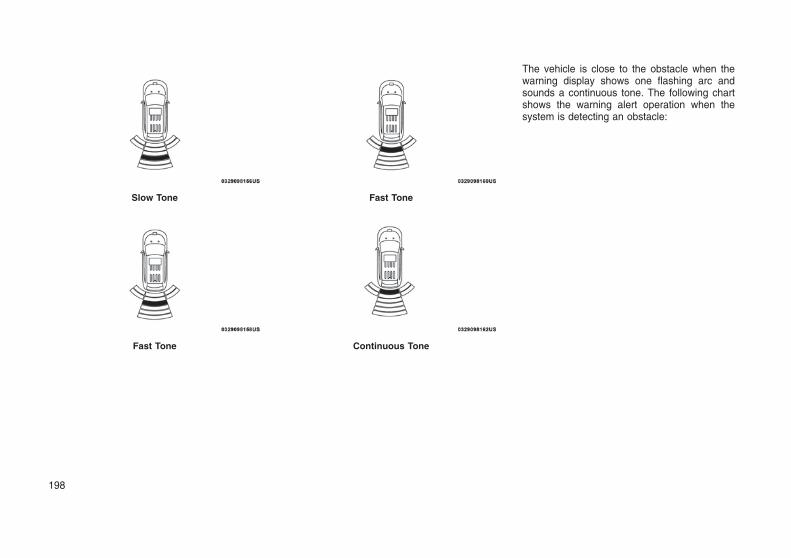
The vehicle is close to the obstacle when thewarning display shows one flashing arc andsounds a continuous tone. The following chartshows the warning alert operation when thesystem is detecting an obstacle:
Slow Tone
Fast Tone
Fast Tone
Continuous Tone
198

WARNING ALERTS
Rear Distance(inches/cm)
Greater than79 inches(200 cm)
79-59 inches(150-100 cm)
59-47 inches(150-120 cm)
47-39 inches(120-100 cm)
39-25 inches(100-65 cm)
25-12 inches(65-30 cm)
Less than12 inches(30 cm)
Audible AlertChime
None Single 1/2Second Tone
Slow Slow Fast Fast Continuous
Arcs-Left None None None None None 2ndFlashing
1stFlashing
Arcs-Center None 6th Solid 5th Solid 4th Solid 3rdFlashing
2ndFlashing
1stFlashing
Arcs-Right None None None None None 2ndFlashing
1stFlashing
Radio VolumeReduced
No Yes Yes Yes Yes Yes Yes
NOTE:ParkSense will reduce the volume of theradio, if on, when the system is sounding anaudio tone.
Adjustable Chime Volume Settings
Rear chime volume settings can be selectedfrom the Customer-Programmable Featuressection of the Uconnect System, refer to“Uconnect Settings” in “Multimedia” for furtherinformation.
The chime volume settings include low, me-dium, and high. The factory default volumesetting is medium.
ParkSense will retain its last known configura-tion state through ignition cycles.
Enabling And Disabling ParkSenseParkSense can be enabled and disabled withthe ParkSense switch.
When the ParkSense switch ispushed to disable the system, theinstrument cluster will display the“PARKSENSE OFF” message forapproximately five seconds. Refer
to “Instrument Cluster Display” in “Getting ToKnow Your Instrument Panel” for further infor-mation. When the gear selector is moved toREVERSE and the system is disabled, theinstrument cluster display will display the
“PARKSENSE OFF” message for as long as thevehicle is in REVERSE.
The ParkSense switch LED will be on whenParkSense is disabled or requires service. TheParkSense switch LED will be off when thesystem is enabled. If the ParkSense switch ispushed, and the system requires service, theParkSense switch LED will blink momentarily,and then the LED will be on.
Service The ParkSense Rear ParkAssist SystemDuring vehicle start up, when the ParkSenseRear Park Assist System has detected a faultedcondition, the instrument cluster will actuate asingle chime, once per ignition cycle, and it will
199

display the “PARKSENSE UNAVAILABLE WIPEREAR SENSORS” or the “PARKSENSE UN-AVAILABLE SERVICE REQUIRED” message.Refer to “Instrument Cluster Display”. When thegear selector is moved to REVERSE and thesystem has detected a faulted condition, theinstrument cluster display will display the"PARKSENSE UNAVAILABLE WIPE REARSENSORS" or "PARKSENSE UNAVAILABLESERVICE REQUIRED" message for as long asthe vehicle is in REVERSE. Under this condi-tion, ParkSense will not operate.
If “PARKSENSE UNAVAILABLE WIPE REARSENSORS” appears in the instrument clusterdisplay make sure the outer surface and theunderside of the rear fascia/bumper is clean andclear of snow, ice, mud, dirt or other obstructionand then cycle the ignition. If the messagecontinues to appear, see an authorized dealer.
If “PARKSENSE UNAVAILABLE SERVICE RE-QUIRED” appears in the instrument cluster dis-play, see an authorized dealer.
Cleaning The ParkSense SystemClean the ParkSense sensors with water, carwash soap and a soft cloth. Do not use rough orhard cloths. Do not scratch or poke the sensors.Otherwise, you could damage the sensors.
ParkSense System UsagePrecautionsNOTE:
• Ensure that the rear bumper is free ofsnow, ice, mud, dirt and debris to keep theParkSense system operating properly.
• Jackhammers, large trucks, and other vi-brations could affect the performance ofParkSense.
• When you turn ParkSense OFF, the instru-ment cluster will display “PARKSENSEOFF” Furthermore, once you turnParkSense off, it remains off until you turnit on again, even if you cycle the ignition.
• When you move the gear selector to theREVERSE position and ParkSense isturned OFF, the instrument cluster displaywill display “PARKSENSE OFF” messagefor as long as the vehicle is in REVERSE.
• ParkSense, when on, will reduce the vol-ume of the radio when it is sounding atone.
• Clean the ParkSense sensors regularly,taking care not to scratch or damagethem. The sensors must not be coveredwith ice, snow, slush, mud, dirt or debris.Failure to do so can result in the systemnot working properly. The ParkSense sys-tem might not detect an obstacle behind
the fascia/bumper, or it could provide afalse indication that an obstacle is behindthe fascia/bumper.
• Use the ParkSense switch to turn theParkSense system OFF if objects such asbicycle carriers, trailer hitches, etc. areplaced within 12 inches (30 cm) from therear fascia/bumper. Failure to do so canresult in the system misinterpreting aclose object as a sensor problem, causingthe “PARKSENSE UNAVAILABLE SER-VICE REQUIRED” message to be dis-played in the instrument cluster display.
• ParkSense should be disabled when theliftgate is in the open position and thevehicle is in REVERSE. An open liftgatecould provide a false indication that anobstacle is behind the vehicle.
WARNING!
• Drivers must be careful when backing upeven when using ParkSense. Alwayscheck carefully behind your vehicle, lookbehind you, and be sure to check forpedestrians, animals, other vehicles, ob-structions, and blind spots before backingup. You are responsible for safety and mustcontinue to pay attention to your surround-ings. Failure to do so can result in seriousinjury or death.
(Continued)
200

WARNING! (Continued)
• Before using ParkSense, it is strongly rec-ommended that the ball mount and hitchball assembly is disconnected from thevehicle when the vehicle is not used fortowing. Failure to do so can result in injuryor damage to vehicles or obstacles be-cause the hitch ball will be much closer tothe obstacle than the rear fascia when theloudspeaker sounds the continuous tone.Also, the sensors could detect the ballmount and hitch ball assembly, dependingon its size and shape, giving a false indi-cation that an obstacle is behind the ve-hicle.
CAUTION!
• ParkSense is only a parking aid and it isunable to recognize every obstacle, includ-ing small obstacles. Parking curbs mightbe temporarily detected or not detected atall. Obstacles located above or below thesensors will not be detected when they arein close proximity.
(Continued)
CAUTION! (Continued)
• The vehicle must be driven slowly whenusing ParkSense in order to be able to stopin time when an obstacle is detected. It isrecommended that the driver looks overhis/her shoulder when using ParkSense.
PARKSENSE FRONT ANDREAR PARK ASSIST — IFEQUIPPEDThe ParkSense Park Assist system providesvisual and audible indications of the distancebetween the rear and/or front fascia and adetected obstacle when backing up or movingforward, e.g. during a parking maneuver. If yourvehicle is equipped with an Automatic Transmis-sion, the vehicle brakes may be automaticallyapplied and released when performing a re-verse parking maneuver if the system detects apossible collision with an obstacle.
NOTE:
• The driver can override the automaticbraking function by pressing the gaspedal, turning ParkSense off viaParkSense switch, or changing the gearwhile the automatic brakes are being ap-plied.
• Automatic brakes will not be available ifESC is not available.
• Automatic brakes will not be available ifthere is a faulted condition detected withthe ParkSense Park Assist system or theBraking System Module.
• The automatic braking function may onlybe applied if the vehicle deceleration isnot enough to avoid colliding with a de-tected obstacle.
• The automatic braking function will not beavailable if vehicle is in 4LO transfer casemode.
• The automatic braking function may notbe applied fast enough for obstacles thatmove toward the rear of the vehicle fromthe left and/or right sides.
• The automatic braking function can beenabled/disabled from the Customer-Programmable Features section of theUconnect System.
• ParkSense will retain its last known con-figuration state for the automatic brakingfunction through ignition cycles.
The automatic braking function is intended toassist the driver in avoiding possible collisionswith detected obstacles when backing up inREVERSE gear.
201

NOTE:
• The driver is always responsible for con-trolling the vehicle.
• The system is provided to assist the driverand not to substitute the driver.
• The driver must stay in full control of thevehicle’s acceleration and braking and isresponsible for the vehicle’s movements.
Refer to ParkSense System Usage Precautionsfor limitations of this system and recommenda-tions.
ParkSense will retain the last system state (en-abled or disabled) from the last ignition cyclewhen the ignition is changed to the ON/RUNposition.
ParkSense can be active only when the gearselector is in REVERSE or DRIVE. If ParkSenseis enabled at one of these gear selector posi-tions, the system will remain active until thevehicle speed is increased to approximately7 mph (11 km/h) or above. A display warning willappear in the instrument cluster display indicat-ing the vehicle is above ParkSense operatingspeed. The system will become active again ifthe vehicle speed is decreased to speeds lessthan approximately 6 mph (9 km/h).
ParkSense SensorsThe four ParkSense sensors, located in the rearfascia/bumper, monitor the area behind the ve-hicle that is within the sensors’ field of view. Thesensors can detect obstacles from approxi-mately 12 inches (30 cm) up to 79 inches (200cm) from the rear fascia/bumper in the horizon-tal direction, depending on the location, typeand orientation of the obstacle.
The six ParkSense sensors, located in the frontfascia/bumper, monitor the area in front of thevehicle that is within the sensors’ field of view.The sensors can detect obstacles from approxi-mately 12 inches (30 cm) up to 47 inches(120 cm) from the front fascia/bumper in thehorizontal direction, depending on the location,type and orientation of the obstacle.
ParkSense Warning DisplayThe ParkSense Warning screen will only bedisplayed if Sound and Display is selected fromthe Customer - Programmable Features sectionof the Uconnect System. Refer to "UconnectSettings” in “Multimedia” for further information.
The ParkSense Warning screen is locatedwithin the instrument cluster display. It providesvisual warnings to indicate the distance betweenthe rear fascia/bumper and/or front fascia/bumper and the detected obstacle. Refer to“Instrument Cluster Display” in “Getting To KnowYour Instrument Panel” for further information.
ParkSense DisplayWhen the vehicle is in REVERSE and an ob-stacle has been detected, the warning displaywill turn on indicating the system status.
The system will indicate a detected obstacle byshowing a single arc in the left and/or right rearregions based on the object’s distance andlocation relative to the vehicle.
If an object is detected in the left and/or rightrear region, the display will show a single arc inthe left and/or right rear region and the systemwill produce a tone. As the vehicle moves closerto the object, the display will show the single arcmoving closer to the vehicle and the tone willchange from a single 1/2 second tone to slow, tofast, to continuous.
Park Assist Ready
202

Single 1/2 Second Tone
Slow Tone
Slow Tone For Rear Only
Fast Tone For Rear Only
Fast Tone
Continuous Tone
203

The vehicle is close to the obstacle when theinstrument cluster display shows one flashingarc and sounds a continuous tone. The followingchart shows the warning alert operation whenthe system is detecting an obstacle:
WARNING ALERTS FOR REAR
Rear Distance(inches/cm)
Greater than79 inches(200 cm)
79-59 inches(150-100 cm)
59-47 inches(150-120 cm)
47-39 inches(120-100 cm)
39-25 inches(100-65 cm)
25-12 inches(65-30 cm)
Less than12 inches(30 cm)
Audible AlertChime
None Single 1/2Second Tone
Slow Slow Fast Fast Continuous
Arcs-Left None None None None None 2ndFlashing
1stFlashing
Arcs-Center None 6th Solid 5th Solid 4th Solid 3rdFlashing
2ndFlashing
1stFlashing
Arcs-Right None None None None None 2ndFlashing
1stFlashing
Radio VolumeReduced
No Yes Yes Yes Yes Yes Yes
204

WARNING ALERTS FOR FRONT
Front Distance(inches/cm)
Greater than47 inches (120 cm)
47-39 inches(120-100 cm)
39-25 inches(100-65 cm)
25-12 inches(65-30 cm)
Less than 12 inches(30 cm)
Audible AlertChime
None None None Fast Continuous
Arcs-Left None None None 2nd Flashing 1st Flashing
Arcs-Center None 4th Solid 3rd Flashing 2nd Flashing 1st Flashing
Arcs-Right None None None 2nd Flashing 1st Flashing
Radio Volume Re-duced
No No No Yes Yes
NOTE:ParkSense will reduce the volume of theradio, if on, when the system is sounding anaudio tone.
Front Park Assist Audible Alerts
ParkSense will turn off the Front Park Assistaudible alert (chime) after approximately 3 sec-onds when an obstacle has been detected, thevehicle is stationary, and brake pedal is applied.
Adjustable Chime Volume Settings
Front and Rear chime volume settings can beselected from the Uconnect System. Refer to"Uconnect Settings” in “Multimedia” for furtherinformation.
The chime volume settings include low, me-dium, and high. The factory default volumesetting is medium.
ParkSense will retain its last known configura-tion state through ignition cycles.
Enabling And Disabling ParkSenseParkSense can be enabled and disabled withthe ParkSense switch.
When the ParkSense switch ispushed to disable the system, theinstrument cluster will display the“PARKSENSE OFF” message forapproximately five seconds. Refer
to “Instrument Cluster Display” in “Getting ToKnow Your Instrument Panel” for further infor-mation. When the gear selector is moved toREVERSE and the system is disabled, theinstrument cluster display will display the“PARKSENSE OFF” message for as long as thevehicle is in REVERSE.
The ParkSense switch LED will be on whenParkSense is disabled or requires service. The
ParkSense switch LED will be off when thesystem is enabled. If the ParkSense switch ispushed, and the system requires service, theParkSense switch LED will blink momentarily,and then the LED will be on.
Service The ParkSense Park AssistSystemDuring vehicle start up, when the ParkSenseSystem has detected a faulted condition, theinstrument cluster will actuate a single chime,once per ignition cycle, and it will display the"PARKSENSE UNAVAILABLE WIPE REARSENSORS", "PARKSENSE UNAVAILABLEWIPE FRONT SENSORS", or the"PARKSENSE UNAVAILABLE SERVICE RE-QUIRED" message for five seconds. When thegear selector is moved to Reverse and thesystem has detected a faulted condition, theinstrument cluster display will display a
205

"PARKSENSE UNAVAILABLE WIPE REARSENSORS", "PARKSENSE UNAVAILABLEWIPE FRONT SENSORS" or "PARKSENSEUNAVAILABLE SERVICE REQUIRED" pop upmessage for five seconds. After five seconds, avehicle graphic will be displayed with "UNAVAIL-ABLE" at either the front or rear sensor locationdepending on where the fault is detected. Thesystem will continue to provide arc alerts for theside that is functioning properly. These arc alertswill interrupt the "PARKSENSE UNAVAILABLEWIPE REAR SENSORS", "PARKSENSE UN-AVAILABLE WIPE FRONT SENSORS", or"PARKSENSE UNAVAILABLE SERVICE RE-QUIRED" messages if an object is detectedwithin the five second pop-up duration. Thevehicle graphic will remain displayed for as longas the vehicle is in REVERSE. Refer to “Instru-ment Cluster Display” in “Getting To Know YourInstrument Panel” for further information.
If "PARKSENSE UNAVAILABLE WIPE REARSENSORS" or "PARKSENSE UNAVAILABLEWIPE FRONT SENSORS" appears in the in-strument cluster display make sure the outersurface and the underside of the rear fascia/bumper and/or front fascia/bumper is clean andclear of snow, ice, mud, dirt or other obstructionand then cycle the ignition. If the messagecontinues to appear see an authorized dealer.
If the "PARKSENSE UNAVAILABLE SERVICEREQUIRED" message appears in the instru-ment cluster display, see an authorized dealer.
Cleaning The ParkSense SystemClean the ParkSense sensors with water, carwash soap and a soft cloth. Do not use rough orhard cloths. Do not scratch or poke the sensors.Otherwise, you could damage the sensors.
ParkSense System UsagePrecautionsNOTE:
• Ensure that the front and rear bumper arefree of snow, ice, mud, dirt and debris tokeep the ParkSense system operatingproperly.
• Jackhammers, large trucks, and other vi-brations could affect the performance ofParkSense.
• When you turn ParkSense off, the instru-ment cluster will display “PARKSENSEOFF.” Furthermore, once you turnParkSense off, it remains off until you turnit on again, even if you cycle the ignition.
• When you move the gear selector to theREVERSE position and ParkSense isturned off, the instrument cluster will dis-play “PARKSENSE OFF” for as long as thevehicle is in REVERSE.
• ParkSense, when on, will reduce the vol-ume of the radio when it is sounding atone.
• Clean the ParkSense sensors regularly,taking care not to scratch or damagethem. The sensors must not be coveredwith ice, snow, slush, mud, dirt or debris.Failure to do so can result in the systemnot working properly. The ParkSense sys-tem might not detect an obstacle behindor in front of the fascia/bumper, or it couldprovide a false indication that an obstacleis behind or in front of the fascia/bumper.
• Use the ParkSense switch to turn theParkSense system off if objects such asbicycle carriers, trailer hitches, etc. areplaced within 12 inches (30 cm) from therear fascia/bumper. Failure to do so canresult in the system misinterpreting aclose object as a sensor problem, causingthe “PARKSENSE UNAVAILABLE SER-VICE REQUIRED” message to be dis-played in the instrument cluster.
• ParkSense should be disabled when theliftgate is in the open position. An openedliftgate could provide a false indicationthat an obstacle is behind the vehicle.
206

WARNING!
• Drivers must be careful when backing upeven when using ParkSense. Alwayscheck carefully behind your vehicle, lookbehind you, and be sure to check forpedestrians, animals, other vehicles, ob-structions, and blind spots before backingup. You are responsible for safety and mustcontinue to pay attention to your surround-ings. Failure to do so can result in seriousinjury or death.
• Before using ParkSense, it is strongly rec-ommended that the ball mount and hitchball assembly is disconnected from thevehicle when the vehicle is not used fortowing. Failure to do so can result in injuryor damage to vehicles or obstacles be-cause the hitch ball will be much closer tothe obstacle than the rear fascia when theloudspeaker sounds the continuous tone.Also, the sensors could detect the ballmount and hitch ball assembly, dependingon its size and shape, giving a false indi-cation that an obstacle is behind the ve-hicle.
CAUTION!
• ParkSense is only a parking aid and it isunable to recognize every obstacle, includ-ing small obstacles. Parking curbs mightbe temporarily detected or not detected atall. Obstacles located above or below thesensors will not be detected when they arein close proximity.
• The vehicle must be driven slowly whenusing ParkSense in order to be able to stopin time when an obstacle is detected. It isrecommended that the driver looks overhis/her shoulder when using ParkSense.
PARKSENSE ACTIVE PARKASSIST SYSTEM — IFEQUIPPEDThe ParkSense Active Park Assist system isintended to assist the driver during parallel andperpendicular parking maneuvers by identifyinga proper parking space, providing audible/visualinstructions, and controlling the steering wheel.The ParkSense Active Park Assist system isdefined as “semi-automatic” since the drivermaintains control of the accelerator, gear selec-tor and brakes. Depending on the driver’s park-ing maneuver selection, the ParkSense ActivePark Assist system is capable of maneuvering a
vehicle into a parallel or a perpendicular parkingspace on either side (i.e., driver side or passen-ger side).
NOTE:
• The driver is always responsible for con-trolling the vehicle, responsible for anysurrounding objects, and must interveneas required.
• The system is provided to assist the driverand not to substitute the driver.
• During a semi-automatic maneuver, if thedriver touches the steering wheel afterbeing instructed to remove their handsfrom the steering wheel, the system willcancel, and the driver will be required tomanually complete the parking maneuver.
• The system may not work in all conditions(e.g. environmental conditions such asheavy rain, snow, etc., or if searching for aparking space that has surfaces that willabsorb the ultrasonic sensor waves).
• New vehicles from the dealership musthave at least 30 miles accumulated beforethe ParkSense Active Park Assist systemis fully calibrated and performs accu-rately. This is due to the system’s dynamicvehicle calibration to improve the perfor-mance of the feature. The system will alsocontinuously perform the dynamic vehiclecalibration to account for differencessuch as over or under inflated tires andnew tires.
207

Enabling And Disabling TheParkSense Active Park AssistSystemThe ParkSense Active Park Assist system canbe enabled and disabled with the ParkSenseActive Park Assist switch, located on the switchpanel below the Uconnect display.
To enable the ParkSense Active Park Assistsystem, push the ParkSense Active Park Assistswitch once (LED turns on).
To disable the ParkSense Active Park Assistsystem, push the ParkSense Active Park Assistswitch again (LED turns off).
The ParkSense Active Park Assist system willturn off automatically for any of the followingconditions:
• The parking maneuver is completed.
• Vehicle speed greater than 18 mph (30 km/h)when searching for a parking space.
• Vehicle speed greater than 5 mph (7 km/h)during active steering guidance into the park-ing space.
• Touching the steering wheel during activesteering guidance into the parking space.
• Pushing the ParkSense Front and Rear ParkAssist switch.
• Driver’s door is opened.
• Rear liftgate is opened.
• Electronic Stability Control/Anti-lock BrakingSystem intervention.
• The ParkSenseActive Park Assist system willallow a maximum of six shifts betweenDRIVE (automatic transmission) or forwardgear (manual transmission) and REVERSE.If the maneuver cannot be completed withinsix shifts, the system will cancel and theinstrument cluster display will instruct thedriver to complete the maneuver manually.
The ParkSense Active Park Assist system willonly operate and search for a parking spacewhen the following conditions are present:
• Gear position is in DRIVE (automatic trans-mission) or in a forward gear (manual trans-mission).
• Ignition is in the RUN position.
• ParkSense Active Park Assist switch isactivated.
• Driver’s door is closed.
• Rear liftgate is closed.
• Vehicle speed is less than 15 mph (25 km/h).
NOTE:If the vehicle is driven above approximately15 mph (25 km/h), the instrument clusterdisplay will instruct the driver to slow down.If the vehicle is driven above approximately18 mph (30 km/h), the system will cancel.The driver must then reactivate the systemby pushing the ParkSense Active Park Assistswitch.
• The outer surface and the underside of thefront and rear fascias/bumpers are clean andclear of snow, ice, mud, dirt or otherobstruction.
When pushed, the LED on the ParkSense Ac-tive Park Assist switch will blink momentarily,and then the LED will turn off if any of the aboveconditions are not present.
Parallel Parking Space AssistanceOperation/DisplayWhen the ParkSense Active Park Assist systemis enabled the “Active ParkSense Searching -Push OK to Switch to Perpendicular” messagewill appear in the instrument cluster display. Youmay switch to perpendicular parking if you de-sire. Push the OK button on the left side steeringwheel switch to change your parking spacesetting.
ParkSense Active Park Assist Switch Location
208

NOTE:
• When searching for a parking space, usethe turn signal indicator to select whichside of the vehicle you want to perform theparking maneuver. The ParkSense ActivePark Assist system will automaticallysearch for a parking space on the passen-ger’s side of the vehicle if the turn signalis not activated.
• The driver needs to make sure that theselected parking space for the maneuverremains free and clear of any obstructions(e.g. pedestrians, bicycles, etc.).
• The driver is responsible to ensure thatthe selected parking space is suitable forthe maneuver and free/clear of anythingthat may be overhanging or protrudinginto the parking space (e.g., ladders, tail-gates, etc. from surroundingobjects/vehicles).
• When seeking for a parking space, thedriver should drive as parallel or perpen-dicular (depending on the type of maneu-ver) to other vehicles as possible.
• The feature will only indicate the last de-tected parking space (example: if passingmultiple available parking spaces, thesystem will only indicate the last detectedparking space for the maneuver).
When an available parking space has beenfound, and the vehicle is not in position, you willbe instructed to move forward to position thevehicle for a parallel parking sequence.
Once the vehicle is in position, you will beinstructed to stop the vehicle’s movement andremove your hands from the steering wheel.
Once the vehicle is at a standstill with yourhands removed from the steering wheel, you willbe instructed to place the gear selector into theREVERSE position.
When the driver places the gear selector into theREVERSE position, the system may instruct thedriver to wait for steering to complete.
Active ParkSense Searching
Space Found — Keep Moving Forward
Space Found — Stop And Remove HandsFrom Wheel
Space Found — Shift To Reverse
209

The system will then instruct the driver to checktheir surroundings and move backward.
NOTE:
• It is the driver’s responsibility to use thebrake and accelerator during the semi-automatic parking maneuver.
• When the system instructs the driver toremove their hands from the steeringwheel, the driver should check their sur-roundings and begin to back up slowly.
• The ParkSense Active Park Assist systemwill allow a maximum of six shifts betweenDRIVE (automatic transmission) or for-ward gear (manual transmission) and RE-VERSE. If the maneuver cannot be com-pleted within six shifts, the system willcancel and the instrument cluster displaywill instruct the driver to complete themaneuver manually.
• The system will cancel the maneuver if thevehicle speed exceeds 5 mph (7 km/h)during active steering guidance into theparking space. The system will provide awarning to the driver at 3 mph (5 km/h)that tells them to slow down. The driver isthen responsible for completing the ma-neuver if the system is canceled.
• If the system is canceled during the ma-neuver for any reason, the driver musttake control of the vehicle.
When the vehicle has reached the end of itsbackward movement, the system will instructthe driver to check their surroundings and stopthe vehicle’s movement.
NOTE:It is the driver’s responsibility to use thebrake and stop the vehicle. The drivershould check their surroundings and be pre-pared to stop the vehicle either when in-structed to, or when driver intervention isrequired.
Check Surroundings — Wait For Steering ToComplete
Check Surroundings — Move Backward
Check Surroundings — STOP
210

Once the vehicle is in a standstill condition, thedriver will be instructed to place the gear selec-tor into the DRIVE position.
When the driver places the gear selector into theDRIVE position, the system may instruct thedriver to wait for steering to complete.
The system will then instruct the driver to checktheir surroundings and move forward.
When the vehicle has reached the end of itsforward movement, the system will instruct thedriver to check their surroundings and stop thevehicle’s movement.
NOTE:It is the driver’s responsibility to use thebrake and stop the vehicle. The drivershould check their surroundings and be pre-pared to stop the vehicle either when in-structed to, or when driver intervention isrequired.
Once the vehicle is in a standstill condition, thedriver will be instructed to place the gear selec-tor into the REVERSE position.
When the driver places the gear selector into theREVERSE position, the system may instruct thedriver to wait for steering to complete.
Check Surroundings — Shift To Drive
Check Surroundings — Wait For Steering ToComplete
Check Surroundings — Move Forward
Check Surroundings — STOP
Check Surroundings — Shift To Reverse
211

The system will then instruct the driver to checktheir surroundings and move backward.
Your vehicle is now in the parallel park position.When the maneuver is complete, the driver willbe instructed to check the vehicle’s parkingposition. If the driver is satisfied with the vehicle
position, they should shift to PARK. The "ActiveParkSense Complete - Check Parking Position"message will be momentarily displayed.
Perpendicular Parking SpaceAssistance Operation/DisplayWhen the ParkSense Active Park Assist systemis enabled, the “Active ParkSense Searching -Push OK to Switch to Perpendicular” messagewill show in the instrument cluster display. Pushthe OK button on the left side steering wheelswitch to change your parking space setting to aperpendicular maneuver. You may switch backto parallel parking if you desire.
Once the driver pushes OK for a perpendicularparking maneuver, the “Active ParkSenseSearching - Push OK to Switch to Parallel”message will appear in the instrument clusterdisplay.
NOTE:
• When searching for a parking space, usethe turn signal indicator to select whichside of the vehicle you want to perform theparking maneuver. The ParkSense ActivePark Assist system will automaticallysearch for a parking space on the passen-ger’s side of the vehicle if the turn signalis not activated.
• The driver needs to make sure that theselected parking space for the maneuverremains free and clear of any obstructions(e.g. pedestrians, bicycles, etc.).
• The driver is responsible to ensure thatthe selected parking space is suitable forthe maneuver and free/clear of anythingthat may be overhanging or protrudinginto the parking space (e.g., ladders, tail-gates, etc. from surroundingobjects/vehicles).
Check Surroundings — Wait For Steering ToComplete
Check Surroundings — Move Backward
Active ParkSense Complete — Check ParkingPosition
Active ParkSense Searching Display
212

• When seeking for a parking space, thedriver should drive as parallel or perpen-dicular (depending on the type of maneu-ver) to other vehicles as possible.
• The feature will only indicate the last de-tected parking space (example: if passingmultiple available parking spaces, thesystem will only indicate the last detectedparking space for the maneuver).
When an available parking space has beenfound, and the vehicle is not in position, you willbe instructed to move forward to position thevehicle for a perpendicular parking sequence.
Once the vehicle is in position, you will beinstructed to stop the vehicle’s movement andremove your hands from the steering wheel.
Once the vehicle is at a standstill with yourhands removed from the steering wheel, you willbe instructed to place the gear selector into theREVERSE position.
When the driver places the gear selector into theREVERSE position, the system may instruct thedriver to wait for steering to complete.
The system will then instruct the driver to checktheir surroundings and move backward.
NOTE:
• It is the driver’s responsibility to use thebrake and accelerator during the semi-automatic parking maneuver.
Space Found — Keep Moving Forward
Space Found — Stop And Remove HandsFrom Wheel
Space Found — Shift To Reverse
Check Surroundings — Wait For Steering ToComplete
Check Surroundings — Move Backward
213

• When the system instructs the driver toremove their hands from the steeringwheel, the driver should check their sur-roundings and begin to back up slowly.
• The ParkSense Active Park Assist systemwill allow a maximum of six shifts betweenDRIVE (automatic transmission) or for-ward gear (manual transmission) and RE-VERSE. If the maneuver cannot be com-pleted within six shifts, the system willcancel and the instrument cluster displaywill instruct the driver to complete themaneuver manually.
• The system will cancel the maneuver if thevehicle speed exceeds 5 mph (7 km/h)during active steering guidance into theparking space. The system will provide awarning to the driver at 3 mph (5 km/h)that tells them to slow down. The driver isthen responsible for completing the ma-neuver if the system is canceled.
• If the system is canceled during the ma-neuver for any reason, the driver musttake control of the vehicle.
When the vehicle has reached the end of itsbackward movement, the system will instructthe driver to check their surroundings and stopthe vehicle’s movement.
NOTE:It is the driver’s responsibility to use thebrake and stop the vehicle. The drivershould check their surroundings and be pre-pared to stop the vehicle either when in-structed to, or when driver intervention isrequired.
Once the vehicle is in a standstill condition, thedriver will be instructed to place the gear selec-tor into the DRIVE position.
When the driver places the gear selector into theDRIVE position, the system may instruct thedriver to wait for steering to complete.
Check Surroundings — STOP Check Surroundings — Shift To Drive
Check Surroundings — Wait For Steering ToComplete
214

The system will then instruct the driver to checktheir surroundings and move forward.
When the vehicle has reached the end of itsforward movement, the system will instruct thedriver to check their surroundings and stop thevehicle’s movement.
NOTE:It is the driver’s responsibility to use thebrake and stop the vehicle. The drivershould check their surroundings and be pre-pared to stop the vehicle either when in-structed to, or when driver intervention isrequired.
Once the vehicle is in a standstill condition, thedriver will be instructed to place the gear selec-tor into the REVERSE position.
When the driver places the gear selector into theREVERSE position, the system may instruct thedriver to wait for steering to complete.
The system will then instruct the driver to checktheir surroundings and move backward.
Check Surroundings — Move Forward
Check Surroundings — STOP
Check Surroundings — Shift To Reverse
Check Surroundings — Wait For Steering ToComplete
Check Surroundings — Move Backward
215

Your vehicle is now in the perpendicular parkposition. When the maneuver is complete, thedriver will be instructed to check the vehicle’sparking position. If the driver is satisfied with thevehicle position, they should shift to PARK. The"Active ParkSense Complete - Check ParkingPosition" message will be momentarily dis-played.
WARNING!
• Drivers must be careful when performingparallel or perpendicular parking maneu-vers even when using the ParkSense Ac-tive Park Assist system. Always checkcarefully behind and in front of your ve-hicle, look behind and in front of you, andbe sure to check for pedestrians, animals,other vehicles, obstructions, and blindspots before backing up and moving for-ward. You are responsible for safety andmust continue to pay attention to yoursurroundings. Failure to do so can result inserious injury or death.
• Before using the ParkSense Active ParkAssist system, it is strongly recommendedthat the ball mount and hitch ball assemblyis disconnected from the vehicle when thevehicle is not used for towing. Failure to doso can result in injury or damage to ve-hicles or obstacles because the hitch ballwill be much closer to the obstacle than therear fascia when the loudspeaker soundsthe continuous tone. Also, the sensorscould detect the ball mount and hitch ballassembly, depending on its size andshape, giving a false indication that anobstacle is behind the vehicle.
CAUTION!
• The ParkSense Active Park Assist systemis only a parking aid and it is unable torecognize every obstacle, including smallobstacles. Parking curbs might be tempo-rarily detected or not detected at all. Ob-stacles located above or below the sensorswill not be detected when they are in closeproximity.
• The vehicle must be driven slowly whenusing the ParkSense Active Park Assistsystem in order to be able to stop in timewhen an obstacle is detected. It is recom-mended that the driver looks over his/hershoulder when using the ParkSense ActivePark Assist system.
LANESENSE — IF EQUIPPED
LaneSense OperationThe LaneSense system is operational at speedsabove 37 mph (60 km/h) and below 112 mph(180 km/h). The LaneSense system uses aforward looking camera to detect lane markingsand measure vehicle position within the laneboundaries.
Active ParkSense Complete — Check ParkingPosition
216

When both lane markings are detected and thedriver unintentionally drifts out of the lane (noturn signal applied), the LaneSense systemprovides a haptic warning in the form of torqueapplied to the steering wheel to prompt thedriver to remain within the lane boundaries. Ifthe driver continues to unintentionally drift out ofthe lane, the LaneSense system provides avisual warning through the instrument clusterdisplay to prompt the driver to remain within thelane boundaries.
The driver may manually override the hapticwarning by applying torque into the steeringwheel at any time.
When only a single lane marking is detected andthe driver unintentionally drifts across the lanemarking (no turn signal applied), the LaneSensesystem provides a visual warning through theinstrument cluster display to prompt the driver toremain within the lane. When only a single lanemarking is detected, a haptic (torque) warningwill not be provided.
NOTE:When operating conditions have been met,the LaneSense system will monitor if thedriver’s hands are on the steering wheel andprovides an audible warning to the driverwhen the driver’s hands are not detected onthe steering wheel. The system will cancel ifthe driver does not return their hands to thewheel.
Turning LaneSense On Or OffThe default status of LaneSense is off. The LEDin LaneSense button will illuminated while thesystem is deactivated.
The LaneSense button is located on the switchpanel below the Uconnect display.
To turn the LaneSense system on, push theLaneSense button (LED turns off). A “La-neSense On” message is shown in the instru-ment cluster display.
To turn the LaneSense system off, push theLaneSense button once (LED turns on).
NOTE:The LaneSense system will retain the lastsystem state on or off from the last ignitioncycle when the ignition is changed to theON/RUN position.
LaneSense Warning MessageThe LaneSense system will indicate the currentlane drift condition through the instrument clus-ter display.LaneSense Warning Button
LaneSense On Message
217

Premium Instrument Cluster Display
When the LaneSense system is on; the lanelines are gray when both of the lane boundarieshave not been detected and the LaneSensetelltale is solid white.
Left Lane Departure — Only Left Lane De-tected
• When the LaneSense system is on, the La-neSense telltale is solid white when only theleft lane marking has been detected and thesystem is ready to provide visual warnings inthe instrument cluster display if an uninten-tional lane departure occurs.
• When the LaneSense system senses thelane has been approached and is in a lanedeparture situation, the left thick lane lineflashes yellow (on/off), the left thin line re-mains solid yellow and the LaneSense telltalechanges from solid white to flashing yellow.
NOTE:The LaneSense system operates with thesimilar behavior for a right lane departurewhen only the right lane marking has beendetected.
Left Lane Departure — Both Lanes Detected
• When the LaneSense system is on, the lanelines turn from gray to white to indicate thatboth of the lane markings have been de-tected. The LaneSense telltale is solid greenwhen both lane markings have been detectedand the system is on to provide visual warn-ings in the instrument cluster display and atorque warning in the steering wheel if anunintentional lane departure occurs.
• When the LaneSense system senses a lanedrift situation, the left thick lane line and leftthin line turn solid yellow. The LaneSensetelltale changes from solid green to solidyellow. At this time torque is applied to thesteering wheel in the opposite direction of thelane boundary.
• For example: If approaching the left side ofthe lane the steering wheel will turn to theright.
System On (Gray Lines/White Telltale)
Lane Approached (Flashing Yellow Thick Line,Solid Yellow Thin Line/Flashing Yellow Telltale)
Lanes Sensed (White Lines/Green Telltale)
218

• When the LaneSense system senses thelane has been approached and is in a lanedeparture situation, the left thick lane lineflashes yellow (on/off) and the left thin lineremains solid yellow. The LaneSense telltalechanges from solid yellow to flashing yellow.At this time torque is applied to the steeringwheel in the opposite direction of the laneboundary.
• For example: If approaching the left side ofthe lane the steering wheel will turn to theright.
NOTE:The LaneSense system operates with thesimilar behavior for a right lane departure.
Changing LaneSense StatusThe LaneSense system has settings to adjustthe intensity of the torque warning and thewarning zone sensitivity (early/late) that you canconfigure through the Uconnect system screen.Refer to “Uconnect Settings” in “Multimedia” forfurther information.
NOTE:
• When enabled the system operates above37 mph (60 km/h) and below 112 mph(180 km/h).
• Use of the turn signal suppresses thewarnings.
• The system will not apply torque to thesteering wheel whenever a safety system
engages. (anti-lock brakes, traction con-trol system, electronic stability control,forward collision warning, etc.).
PARKVIEW REAR BACK UPCAMERA — IF EQUIPPEDYour vehicle may be equipped with theParkView Rear Back Up Camera that allows youto see an on-screen image of the rear surround-ings of your vehicle whenever the gear selectoris put into REVERSE. The image will be dis-played on the Navigation/Multimedia radio dis-play screen along with a caution note to “checkentire surroundings” across the top of thescreen. After five seconds this note will disap-pear. The ParkView camera is located on therear of the vehicle above the rear License plate.
When the vehicle is shifted out of REVERSE(with camera delay turned off), the rear cameramode is exited and the navigation or audioscreen appears again.
When the vehicle is shifted out of REVERSE(with camera delay turned on), the rear viewimage with dynamic grid lines will be displayedfor up to 10 seconds after shifting out of RE-VERSE unless the forward vehicle speed ex-ceeds 8 mph (13 km/h), the transmission isshifted into PARK or the ignition is switched tothe OFF position.
Lane Sensed (Solid Yellow Thick Line, SolidYellow Thin Line/Solid Yellow Telltale)
Lane Approached (Flashing Yellow Thick Line,Solid Yellow Thin Line/Flashing Yellow Telltale)
219

NOTE:The ParkView Rear Back Up Camera hasprogrammable modes of operation that maybe selected through the Uconnect System.Refer to “Uconnect Settings” in “Multime-dia” for further information.
When enabled, active guide lines are overlaidon the image to illustrate the width of the vehicleand its projected backup path based on thesteering wheel position. A dashed center lineoverlay indicates the center of the vehicle toassist with parking or aligning to a hitch/receiver.Different colored zones indicate the distance to
the rear of the vehicle. The following tableshows the approximate distances for each zone:
Zone Distance To The Rear Of The Vehicle
Red 0 - 1 ft (0 - 30 cm)
Yellow 1 ft - 6.5 ft (30 cm - 2 m)
Green 6.5 ft or greater (2 m or greater)
WARNING!
Drivers must be careful when backing upeven when using the ParkView Rear Back UpCamera. Always check carefully behind yourvehicle, and be sure to check for pedestrians,animals, other vehicles, obstructions, or blindspots before backing up. You are responsiblefor the safety of your surroundings and mustcontinue to pay attention while backing up.Failure to do so can result in serious injury ordeath.
CAUTION!
• To avoid vehicle damage, ParkView shouldonly be used as a parking aid. TheParkView camera is unable to view everyobstacle or object in your drive path.
• To avoid vehicle damage, the vehicle mustbe driven slowly when using ParkView tobe able to stop in time when an obstacle isseen. It is recommended that the driverlook frequently over his/her shoulder whenusing ParkView.
NOTE:If snow, ice, mud, or any foreign substancebuilds up on the camera lens, clean the lens,rinse with water, and dry with a soft cloth. Donot cover the lens.
Rear Camera — Viewing At Speed
When the vehicle is in park, neutral or drive, theRear View Camera can be activated with the“Rear View Camera” button in the Controlsmenu. This feature allows the customer to moni-tor the area directly behind the vehicle (or trailer,if equipped) for up to ten seconds while atspeed. If the vehicle speed remains below8 mph (13 km/h), the Rear View Camera imagewill be displayed continuously wntil deactivatedvia the “X” button on the touchscreen.
220

REFUELING THE VEHICLE —GASOLINE ENGINE1. Push the fuel filler door release switch (lo-cated under the headlamp switch).
2. Open the fuel filler door.
NOTE:In certain cold conditions, ice may preventthe fuel door from opening. If this occurs,lightly push on the fuel door to break the icebuildup and re-release the fuel door usingthe inside release button. Do not pry on thedoor.
3. There is no fuel filler cap. A flapper doorinside the pipe seals the system.
4. Insert the fuel nozzle fully into the filler pipe,the nozzle opens and holds the flapper doorwhile refueling.
5. Fill the vehicle with fuel, when the fuel nozzle“clicks” or shuts off the fuel tank is full.
6. Wait 5 seconds before removing the fuelnozzle to allow fuel to drain from nozzle.
7. Remove the fuel nozzle and close the fueldoor.
Emergency Gas Can Refueling
• Most gas cans will not open the flapper door.
• A funnel is provided to open the flapper doorto allow emergency refueling with a gas can.
• Retrieve funnel from the spare tire storagearea.
• Insert funnel into same filler pipe opening asthe fuel nozzle.
• Ensure funnel is inserted fully to hold flapperdoor open.
• Pour fuel into funnel opening.
• Remove funnel from filler pipe, clean off priorto putting back in the spare tire storage area.
WARNING!
• Never have any smoking materials lit in ornear the vehicle when the fuel door is openor the tank is being filled.
• Never add fuel when the engine is running.This is in violation of most state and federalfire regulations and may cause the “Mal-function Indicator Light” to turn on.
• A fire may result if fuel is pumped into aportable container that is inside of a ve-hicle. You could be burned. Always placefuel containers on the ground while filling.
CAUTION!
To avoid fuel spillage and overfilling, do not“top off” the fuel tank after filling.
Fuel Filler Door Release Switch
Fuel Filler Door Latch
221

Emergency Fuel Filler Door ReleaseIf you are unable to open the fuel filler door, usethe fuel filler door emergency release.
1. Open the liftgate.
2. Push the inboard edge of the left storage binto the center, this will pop up the outboardedge.
3. Grab popped up outboard edge with otherhand to disengage snaps.
4. Remove the storage bin.
5. Pull the release cable to open the fuel door,push the release cable back to the homeposition to re-seat the fuel door latch to theclosed position.
NOTE:If the fuel door does not latch after themanual release cable has been activated, theactuator latch should be manually returnedto the closed position.
REFUELING THE VEHICLE —DIESEL ENGINE1. Press the fuel filler door release switch (lo-cated under the headlamp switch).
2. Open the fuel filler door.
1 — Fuel Fill Location2 — Diesel Exhaust Fluid Fill Location
NOTE:There is no fuel filler cap. A flapper doorinside the filler pipe seals the system.
3. Insert the fuel nozzle fully into the filler pipe –the nozzle opens and holds the flapper doorwhile refueling.
4. Fill the vehicle with fuel – when the fuelnozzle “clicks” or shuts off the fuel tank is full.
5. Remove the fuel nozzle and close the fueldoor.
Release Cable
Fuel Filler Door Release Switch
Fuel and Diesel Exhaust Fluid Fill Location
222

Emergency Fuel Can Refueling
Most fuel cans will not open the flapper door.
A funnel is provided to open the flapper door toallow emergency refueling with a fuel can.
1. Retrieve funnel from the spare tire kit.
2. Insert funnel into same filler pipe opening asthe fuel nozzle.
NOTE:Ensure funnel is inserted fully to hold flap-per door open.
3. Pour fuel into funnel opening.
4. Remove funnel from filler pipe, clean off priorto putting back in the spare tire kit.
WARNING!
• Never have any smoking materials lit in ornear the vehicle when the fuel door is openor the tank is being filled.
• Never add fuel when the engine is running.This is in violation of most state and federalfire regulations and may cause the “Mal-function Indicator Light” to turn on.
• A fire may result if fuel is pumped into aportable container that is inside of a ve-hicle. You could be burned. Always placefuel containers on the ground while filling.
CAUTION!
To avoid fuel spillage and overfilling, do not“top off” the fuel tank after filling.
Avoid Using Contaminated FuelFuel that is contaminated by water or dirt cancause severe damage to the engine fuel sys-tem. Proper maintenance of the engine fuel filter
and fuel tank is essential. Refer to “DealerService” in “Servicing And Maintenance” forfurther information.
Bulk Fuel Storage — Diesel FuelIf you store quantities of fuel, good maintenanceof the stored fuel is also essential. Fuel contami-nated with water will promote the growth of“microbes.” These microbes form “slime” thatwill clog the fuel filtration system and lines. Draincondensation from the supply tank and changethe line filter on a regular basis.
NOTE:When a diesel engine is allowed to run out offuel, air is pulled into the fuel system.
If the vehicle will not start, refer to “DealerService / Priming If The Engine Has Run Out OfFuel” in “Servicing And Maintenance” for furtherinformation.
WARNING!
Do not open the high pressure fuel systemwith the engine running. Engine operationcauses high fuel pressure. High pressure fuelspray can cause serious injury or death.
Diesel Exhaust FluidYour vehicle is equipped with a Selective Cata-lytic Reduction system to meet the very strin-gent diesel emissions standards required by theEnvironmental Protection Agency.
Fuel Fill Funnel Location
Emergency Fuel Fill Location
223

The purpose of the SCR system is to reducelevels of NOx (oxides of nitrogen emitted fromengines) that are harmful to our health and theenvironment to a near-zero level. Small quanti-ties of Diesel Exhaust Fluid (DEF) is injectedinto the exhaust upstream of a catalyst where,when vaporized, it converts smog-forming nitro-gen oxides (NOx) into harmless nitrogen (N2)and water vapor (H2O), two natural componentsof the air we breathe. You can operate with thecomfort that your vehicle is contributing to acleaner, healthier world environment for this andgenerations to come.
System OverviewThis vehicle is equipped with a Diesel ExhaustFluid (DEF) injection system and a SelectiveCatalytic Reduction (SCR) catalyst to meet theemission requirements.
The DEF injection system consists of the follow-ing components:
• DEF tank
• DEF pump
• DEF injector
• Electronically-heated DEF lines
• NOx sensors
• Temperature sensors
• SCR catalyst
The DEF injection system and SCR catalystenable the achievement of diesel emissionsrequirements; while maintaining outstandingfuel economy, drivability, torque and power rat-ings.
Refer to “Instrument Cluster Display” in “GettingTo Know Your Instrument Panel” for systemmessages and warnings.
NOTE:
• Your vehicle is equipped with a DEF injec-tion system. You may occasionally hearan audible clicking noise from under thevehicle at a stop. This is normal operation.
• The DEF pump will run for a period of timeafter engine shutdown to purge the DEFsystem. This is normal operation and maybe audible from the rear of the vehicle.
Diesel Exhaust Fluid StorageDiesel Exhaust Fluid (DEF) is considered a verystable product with a long shelf life. If DEF iskept in temperatures between 10° and 90°F(-12° and 32°C), it will last a minimum of oneyear.
DEF is subject to freezing at the lowest tem-peratures. For example, DEF may freeze attemperatures at or below 12° F (-11° C). Thesystem has been designed to operate in thisenvironment.
NOTE:When working with DEF, it is important toknow that:
• Any containers or parts that come intocontact with DEF must be DEF compatible(plastic or stainless steel). Copper, brass,aluminum, iron or non-stainless steelshould be avoided as they are subject tocorrosion by DEF.
• If DEF is spilled, it should be wiped upcompletely.
Adding Diesel Exhaust FluidThe DEF gauge (located on the instrumentcluster display) will display the level of DEFremaining in the tank. Refer to “Instrument Clus-ter Display” in “Getting To Know Your InstrumentPanel” for further information.
NOTE:Driving conditions (altitude, vehicle speed,load, etc.) will effect the amount of DEF thatis used in your vehicle.
DEF Fill Procedure
NOTE:Refer to “Fluids And Lubricants” in the“Technical Specifications” section for thecorrect fluid type.
224

1. Remove cap from DEF fill inlet (located infuel door).
2. Insert DEF fill adapter/nozzle into DEF fillinlet.
NOTE:
• The DEF gauge may take up to five sec-onds to update after adding a gallon ormore of Diesel Exhaust Fluid (DEF) to theDEF tank. If you have a fault related to theDEF system, the gauge may not update tothe new level. See your authorized dealerfor service.
• The DEF gauge may also not immediatelyupdate after a refill if the temperature ofthe DEF fluid is below 12F (-11C). The DEFline heater will possibly warm up the DEFfluid and allow the gauge to update after aperiod of run time. Under very cold condi-tions, it is possible that the gauge may notreflect the new fill level for several drives.
CAUTION!
• To avoid DEF spillage, and possible dam-age to the DEF tank from overfilling, do not“top off” the DEF tank after filling.
• DO NOTOVERFILL. DEF will freeze below12ºF (-11ºC). The DEF system is designedto work in temperatures below the DEFfreezing point, however, if the tank is over-filled and freezes, the system could bedamaged.
• When DEF is spilled, clean the area imme-diately with water and use an absorbentmaterial to soak up the spills on theground.
• Do not attempt to start your engine if DEFis accidentally added to the diesel fuel tankas it can result in severe damage to yourengine, including but not limited to failure ofthe fuel pump and injectors.
(Continued)
CAUTION! (Continued)
• Never add anything other than DEF to thetank – especially any form of hydrocarbonsuch as diesel fuel, fuel system additives,gasoline, or any other petroleum-basedproduct. Even a very small amount ofthese, less than 100 parts per million orless than 1 oz. per 78 gallons (295 liters)will contaminate the entire DEF systemand will require replacement. If owners usea container, funnel or nozzle when refillingthe tank, it should either be new or one thatis has only been used for adding DEF.MOPAR provides an attachable nozzlewith its DEF for this purpose.
3. Stop filling the DEF tank immediately whenany of the following happen: DEF stopsflowing from the fill bottle into the DEF fillinlet, DEF splashes out the fill inlet, or a DEFpump nozzle automatically shuts off.
4. Reinstall cap onto DEF fill inlet.
TRAILER TOWINGIn this section you will find safety tips andinformation on limits to the type of towing youcan reasonably do with your vehicle. Beforetowing a trailer, carefully review this informationto tow your load as efficiently and safely aspossible.
Fuel and Diesel Exhaust Fluid Fill Location
1 — Diesel Fuel Filler2 — Diesel Exhaust Fluid Filler
225

To maintain the New Vehicle Limited Warrantycoverage, follow the requirements and recom-mendations in this manual concerning vehiclesused for trailer towing.
Common Towing DefinitionsThe following trailer towing related definitionswill assist you in understanding the followinginformation:
Gross Vehicle Weight Rating (GVWR)The GVWR is the total allowable weight of yourvehicle. This includes driver, passengers, cargoand tongue weight. The total load must belimited so that you do not exceed the GVWR.Refer to “Vehicle Loading/Vehicle CertificationLabel” in “Starting And Operating” for furtherinformation.
Gross Trailer Weight (GTW)The GTW is the weight of the trailer plus theweight of all cargo, consumables and equipment(permanent or temporary) loaded in or on thetrailer in its "loaded and ready for operation"condition.
The recommended way to measure GTW is toput your fully loaded trailer on a vehicle scale.The entire weight of the trailer must be sup-ported by the scale.
WARNING!
If the gross trailer weight is 5,000 lbs(2 267 kg) or more, it is recommended to use
(Continued)
WARNING! (Continued)
a weight-distributing hitch to ensure stablehandling of your vehicle. If you use a stan-dard weight-carrying hitch, you could losecontrol of your vehicle and cause a collision.
Gross Combination Weight Rating (GCWR)The GCWR is the total allowable weight of yourvehicle and trailer when weighed in combina-tion.
Gross Axle Weight Rating (GAWR)The GAWR is the maximum capacity of the frontand rear axles. Distribute the load over the frontand rear axles evenly. Make sure that you do notexceed either front or rear GAWR. Refer to“Vehicle Loading/Vehicle Certification Label” in“Starting And Operating” for further information.
WARNING!
It is important that you do not exceed themaximum front or rear GAWR. A dangerousdriving condition can result if either rating isexceeded. You could lose control of the ve-hicle and have a collision.
Tongue Weight (TW)The tongue weight is the downward force ex-erted on the hitch ball by the trailer. You mustconsider this as part of the load on your vehicle.
Trailer Frontal AreaThe frontal area is the maximum height multi-plied by the maximum width of the front of atrailer.
Breakaway Cable AttachmentEuropean braking regulations for braked trailersup to 7,700 lbs (3 500 kg), require trailers to befitted with either a secondary coupling or break-away cable.
The recommended location for attaching thenormal trailer’s breakaway cable is in thestamped slot located on the sidewall of the hitchreceiver.
With Attachment Point
• For detachable tow bar pass the cablethrough the attachment point and clip it backonto itself or attach the clip directly to thedesignated point.
Detachable Ball Clip Loop Method
226

• For fixed ball tow bar attach the clip directly tothe designated point. This alternative must bespecifically permitted by the trailer manufac-turer since the clip may not be sufficientlystrong for use in the way.
Without Attachment Points
• For detachable ball tow bar, you must followthe recommended manufacturer or supplierprocedure.
• For fixed ball tow bar, loop the cable aroundthe neck of the tow ball. If you fit the cable likethis, use a single loop only.
Fixed Ball Clip Loop MethodDetachable Ball Neck Loop Method
Fixed Ball Neck Loop Method
227

Trailer Towing Weights (Maximum Trailer Weight Ratings) — Non SRTThe following chart provides the maximum trailer weight ratings towable for your given drivetrain.
Engine/Transmission Max. GTW (Gross Trailer Wt.) — withTrailer Brake
Max. GTW (Gross Trailer Wt.) — with-out Trailer Brake Tongue Wt. (See Note)
3.6L Gasoline — StandardCooling System 3,500 lbs (1,588 kg) 1,653 lbs (750 kg) 174 lbs (79 kg)
3.6L Gasoline — HeavyDuty Cooling System 5,000 lbs (2,268 kg) 1,653 lbs (750 kg) 310 lbs (141 kg)
5.7L Gasoline — StandardCooling System 5,000 lbs (2,268 kg) 1,653 lbs (750 kg) 250 lbs (113 kg)
5.7L Gasoline — HeavyDuty Cooling System (ex-cept Summit)
7,716 lbs (3,500 kg) 1,653 lbs (750 kg) 386 lbs (175 kg)
5.7L Gasoline — SummitModels With Heavy DutyCooling System
6,500 lbs (2,949 kg) 1,653 lbs (750 kg) 386 lbs (175 kg)
3.0L Diesel — Rear-WheelDrive Models
6,500 lbs (2,949 kg) 1,653 lbs (750 kg) 324 lbs (147 kg)
3.0L Diesel — All-WheelDrive Models (except Summit)
7,716 lbs (3,500 kg) 1,653 lbs (750 kg) 386 lbs (175 kg)
3.0L Diesel — Summit Mod-els
6,500 lbs (2,949 kg) 1,653 lbs (750 kg) 324 lbs (147 kg)
When towing a trailer the technically permissible laden weight may be exceeded by not more than 10% or 220 lbs (100 kg), whichever is lower pro-vided that the operating speed is restricted to 62 mph (100 km/h) or less.
NOTE:The trailer tongue weight must be considered as part of the combined weight of occupants and cargo, and should never exceed the weight refer-enced on the Tire and Loading Information placard. Refer to “Tires” in “Servicing And Maintenance” for further information.
228

Trailer Hitch Receiver CoverRemoval (Summit Models) — IfEquippedYour vehicle may be equipped with a trailer hitchreceiver cover, this must be removed to accessthe trailer hitch receiver (if equipped). This hitchreceiver cover is located at the bottom center ofthe rear fascia.
1. Turn the two locking retainers located at thebottom of the hitch receiver cover a 1/4 turncounterclockwise.
NOTE:Use a suitable tool such as a coin in the slotof the locking retainer if needed for addedleverage.
2. Pull the bottom of the cover outward (to-wards you), pull downwards to disengage thetabs located at the top of the hitch receivercover.
To reinstall the hitch receiver cover after towingrepeat the procedure in reverse order.
NOTE:Be sure to engage all tabs of the hitchreceiver cover in the bumper fascia prior toinstallation.
Trailer And Tongue WeightNever exceed the maximum tongue weightstamped on your bumper or trailer hitch.
Consider the following items when computingthe weight on the rear axle of the vehicle:
• The tongue weight of the trailer.
• The weight of any other type of cargo orequipment put in or on your vehicle.
• The weight of the driver and all passengers.
NOTE:Remember that everything put into or on thetrailer adds to the load on your vehicle. Also,additional factory-installed options ordealer-installed options must be consideredas part of the total load on your vehicle.Refer to the “Tire And Loading Information”placard for the maximum combined weightof occupants and cargo for your vehicle.
Towing RequirementsTo promote proper break-in of your new vehicledrivetrain components, the following guidelinesare recommended.
CAUTION!
• Do not tow a trailer at all during the first500 miles (805 km) the new vehicle isdriven. The engine, axle or other partscould be damaged.
• Then, during the first 500 miles (805 km)that a trailer is towed, do not drive over50 mph (80 km/h) and do not make startsat full throttle. This helps the engine andother parts of the vehicle wear in at theheavier loads.
Perform the maintenance listed in the “Sched-uled Servicing”. Refer to “Scheduled Servicing”in “Servicing And Maintenance” for the proper
Hitch Receiver Cover
1 — Hitch Receiver Cover2 — Locking Retainers
Hitch Receiver Cover
229

maintenance intervals. When towing a trailer,never exceed the GAWR or GCWR ratings.
WARNING!
Improper towing can lead to a collision. Fol-low these guidelines to make your trailer
towing as safe as possible:• Make certain that the load is secured in thetrailer and will not shift during travel. Whentrailering cargo that is not fully secured,dynamic load shifts can occur that may bedifficult for the driver to control. You couldlose control of your vehicle and have acollision.
• When hauling cargo or towing a trailer, donot overload your vehicle or trailer. Over-loading can cause a loss of control, poorperformance or damage to brakes, axle,engine, transmission, steering, suspen-sion, chassis structure or tires.
• Safety chains must always be used be-tween your vehicle and trailer. Always con-nect the chains to the hook retainers of thevehicle hitch. Cross the chains under thetrailer tongue and allow enough slack forturning corners.
(Continued)
WARNING! (Continued)
• Vehicles with trailers should not be parkedon a grade. When parking, apply the park-ing brake on the tow vehicle. Put the towvehicle transmission in PARK. For four-wheel drive vehicles, make sure the trans-fer case is not in NEUTRAL. Always, blockor "chock" the trailer wheels.
• GCWR must not be exceeded.• Total weight must be distributed be-
tween the tow vehicle and the trailersuch that the following four ratings arenot exceeded:
1. GVWR
2. GTW
3. GAWR
4. Tongue weight rating for the trailer hitchutilized.
Towing Requirements — Tires
• Do not attempt to tow a trailer while using acompact spare tire.
• Proper tire inflation pressures are essential tothe safe and satisfactory operation of yourvehicle. Refer to “Tires” in “Servicing AndMaintenance” for proper tire inflationprocedures.
• Check the trailer tires for proper tire inflationpressures before trailer usage.
• Check for signs of tire wear or visible tiredamage before towing a trailer. Refer to“Tires” in “Servicing And Maintenance” for theproper inspection procedure.
• When replacing tires, refer to “Tires” in “Ser-vicing And Maintenance” for the proper tirereplacement procedures. Replacing tires witha higher load carrying capacity will not in-crease the vehicle’s GVWR and GAWRlimits.
Towing Requirements — Trailer Brakes
• Do not interconnect the hydraulic brake sys-tem or vacuum system of your vehicle withthat of the trailer. This could cause inad-equate braking and possible personal injury.
• An electronically actuated trailer brake con-troller is required when towing a trailer withelectronically actuated brakes. When towinga trailer equipped with a hydraulic surgeactuated brake system, an electronic brakecontroller is not required.
• Trailer brakes are recommended for trailersover 1,000 lbs (453 kg) and required fortrailers in excess of 2,000 lbs (907 kg).
230

WARNING!
• Do not connect trailer brakes to your vehi-cle’s hydraulic brake lines. It can overloadyour brake system and cause it to fail. Youmight not have brakes when you needthem and could have a collision.
• Towing any trailer will increase your stop-ping distance. When towing you shouldallow for additional space between yourvehicle and the vehicle in front of you.Failure to do so could result in a collision.
CAUTION!
If the trailer weighs more than 1,000 lbs(453 kg) loaded, it should have its ownbrakes and they should be of adequate ca-pacity. Failure to do this could lead to accel-erated brake lining wear, higher brake pedaleffort, and longer stopping distances.
Towing Requirements — Trailer Lights AndWiringWhenever you pull a trailer, regardless of thetrailer size, stoplights and turn signals on thetrailer are required for motoring safety.
The Trailer Tow Package may include a four-and seven-pin wiring harness. Use a factoryapproved trailer harness and connector.
NOTE:Do not cut or splice wiring into the vehicle’swiring harness.
The electrical connections are all complete tothe vehicle but you must mate the harness to atrailer connector. Refer to the following illustra-tions.
Seven-Pin Connector
1 — Battery 5 — Ground2 — Backup Lamps 6 — Left Stop/Turn3 — Right Stop/Turn 7 — Running Lamps4 — Electric Brakes
13–Pin Connector — If Equipped
231

Pin Number Function Wire Color
1 Left Turn Signal Black/White
2 Rear Fog Light White
3 a Ground/Common Return for Contacts (Pins)1 and 2 and 4 to 8
Brown
4 Right Turn Signal Black/Green
5 Right Rear Position, Side Marker Lights, andRear Registration Plate Illumination Device. b
Green/Red
6 Stop Lights Black/Red
7 Left Rear Position, Side Marker Lights, andRear Registration Plate Illumination Device. b
Green/Black
8 Reverse lights Blue/Red
9 Permanent Power Supply (+12V) Red
10 Power Supply Controlled by Ignition Switch(+12V)
Yellow
11 a Return for Contact (Pin) 10 Yellow/Brown
12 Reserve for Future Allocation –
13 a Return for Contact (Pin) 9 Red/Brown
NOTE:The allocation pin 12 has been changed from “Coding for coupled Trailer” to “Reserve for Future Allocation.”a The three return circuits shall not be connected electrically in the trailer.b The rear position registration plate illumination device shall be connected such that no light of the device has a common connection with both pins5 and 7.
232

Towing TipsBefore setting out on a trip, practice turning,stopping, and backing up the trailer in an arealocated away from heavy traffic.
Automatic TransmissionSelect the DRIVE range when towing. Thetransmission controls include a drive strategy toavoid frequent shifting when towing. However, iffrequent shifting does occur while in DRIVE,select TOW mode, or use the AutoStick shiftcontrol to manually select a lower gear.
NOTE:Using TOW mode, or selecting a lower gear(using the AutoStick shift control) while op-erating the vehicle under heavy loading con-ditions, will improve performance and ex-tend transmission life by reducing excessiveshifting and heat buildup. This action willalso provide better engine braking.
TOW Mode
To reduce the potential for automatic transmis-sion overheating, select TOW mode when driv-ing in hilly areas, or select a lower gear (usingthe AutoStick shift paddles) on more severegrades.
AutoStick
• When using the AutoStick shift control, selectthe highest gear that allows for adequateperformance and avoids frequent downshifts.For example, choose “5” if the desired speedcan be maintained. Choose “4” or “3” ifneeded to maintain the desired speed.
• To prevent excess heat generation, avoidcontinuous driving at high RPM. Reduce ve-hicle speed as necessary to avoid extendeddriving at high RPM. Return to a higher gearor vehicle speed when grade and road con-ditions allow.
Electronic Speed Control — If Equipped
• Do not use in hilly terrain or with heavy loads.
• When using the speed control, if you experi-ence speed drops greater than 10 mph(16 km/h), disengage until you can get backto cruising speed.
• Use speed control in flat terrain and with lightloads to maximize fuel efficiency.
Cooling SystemTo reduce potential for engine and transmissionoverheating, take the following actions:
City Driving
When stopped for short periods, shift the trans-mission into NEUTRAL and increase engine idlespeed.
Highway Driving
Reduce speed.
Air Conditioning
Turn off temporarily.
233

Trailer Hitch Attaching PointsYour vehicle will require extra equipment to towa trailer safely and efficiently. The trailer towhitch must be attached to your vehicle using theprovided attaching points on the vehicle’s frame.Refer to the following chart to determine theaccurate attaching points. Other equipment,such as trailer sway controls and braking equip-
ment, trailer equalizing (leveling) equipment andlow profile mirrors, may also be required orstrongly recommended.
Trailer Tow Hitch Attaching Points And Overhang Dimensions
Fixed, Detach and Retractable Hitch
A 1.85 ft. (565 mm)
B 2.09 ft. (636 mm)
C 2.32 ft. (707 mm)
D 2.4 ft. (733 mm)
E 1.62 ft. (494 mm)
F 1.47 ft. (447 mm)
G (Maximum Overhang) 3.59 ft. (1093 mm)
234

RECREATIONAL TOWING (BEHIND MOTORHOME, ETC.)
Towing This Vehicle Behind Another Vehicle
Towing Condition Wheels OFF The Ground Two-Wheel Drive Models Four-Wheel Drive Mod-els Without 4–LO Range
Four-Wheel Drive ModelsWith 4–LO Range
Flat Tow NONE NOT ALLOWED NOT ALLOWED
See Instructions• Transmission in PARK• Transfer case in NEU-TRAL (N)
• Tow in forward direction• Disconnect negative bat-tery cable
Dolly TowFront NOT ALLOWED NOT ALLOWED NOT ALLOWED
Rear OK NOT ALLOWED NOT ALLOWED
On Trailer ALL OK OK OK
NOTE:
• When towing your vehicle, always followapplicable state and provincial laws. Con-tact state and provincial Highway Safetyoffices for additional details.
• Vehicles equipped with Quadra-Lift mustbe placed in Transport Mode before tyingthem down (from the body) on a trailer orflatbed truck. Refer to “Quadra-Lift” in“Starting and Operating” for more infor-mation. If the vehicle cannot be placed inTransport mode (for example, engine willnot run), tie-downs should be fastenedover the tires using specific straps (not to
the body). Failure to follow these instruc-tions may cause fault codes to be setand/or cause loss of proper tie-down ten-sion.
Recreational Towing-Two WheelDrive ModelsDO NOT flat tow this vehicle. Damage to thedrivetrain will result.
Recreational towing (for two-wheel drive mod-els) is allowed ONLY if the rear wheels are OFFthe ground. This may be accomplished using atow dolly or vehicle trailer. If using a tow dolly,follow this procedure:
1. Properly secure the dolly to the tow vehicle,following the dolly manufacturer’s instruc-tions.
NOTE:If vehicle is equipped with Quadra-Lift airsuspension, ensure the vehicle is set toNormal Ride Height.
2. Drive the rear wheels onto the tow dolly.
3. Firmly apply the parking brake. Shift thetransmission into PARK.
4. Turn the ignition OFF.
235

5. Properly secure the rear wheels to the dolly,following the dolly manufacturer’s instruc-tions.
6. Turn the ignition to the ON/RUN mode, butdo not start the engine.
7. Confirm that the steering column is unlocked.
8. Install a suitable clamping device, designedfor towing, to secure the front wheels in thestraight position.
9. Disconnect the negative battery cable, andsecure it away from the battery post.
NOTE:Disconnecting your vehicle battery willerase radio presets and may affect othervehicle settings. It may also trigger variousfault codes, causing MIL illumination whenthe battery is reconnected.
CAUTION!
Towing with the rear wheels on the groundwill cause severe transmission damage.Damage from improper towing is not coveredunder the New Vehicle Limited Warranty.
Recreational Towing — Quadra-Trac I(Single-Speed Transfer Case)Four-Wheel Drive ModelsRecreational towing is not allowed. Thesemodels do not have a NEUTRAL (N) position inthe transfer case.
NOTE:This vehicle may be towed on a flatbed orvehicle trailer provided all four wheels areOFF the ground.
CAUTION!
Towing this vehicle in violation of the aboverequirements can cause severe transmissionand/or transfer case damage. Damage fromimproper towing is not covered under theNew Vehicle Limited Warranty.
Recreational Towing — Quadra–TracII/Quadra–Drive II Four-Wheel DriveModelsThe transfer case must be shifted into NEU-TRAL (N) and the transmission must be in PARKfor recreational towing. The NEUTRAL (N) se-lection button is adjacent to the transfer caseselector switch. Shifts into and out of transfercase NEUTRAL (N) can take place with theselector switch in any mode position.
CAUTION!
• DO NOT dolly tow any 4WD vehicle. Tow-ing with only one set of wheels on theground (front or rear) will cause severetransmission and/or transfer case damage.Tow with all four wheels either ON theground, or OFF the ground (using a vehicletrailer).
• Tow only in a forward direction. Towing thisvehicle backwards can cause severe dam-age to the transfer case.
• The transmission must be in PARK forrecreational towing.
• Before recreational towing, perform theprocedure outlined under “Shifting intoNEUTRAL (N)” to be certain that the trans-fer case is fully in NEUTRAL (N). Other-wise, internal damage will result.
• Towing this vehicle in violation of the aboverequirements can cause severe transmis-sion and/or transfer case damage. Dam-age from improper towing is not coveredunder the New Vehicle Limited Warranty.
• Do not use a bumper-mounted clamp-ontow bar on your vehicle. The bumper facebar will be damaged.
236

Shifting Into NEUTRAL (N)
WARNING!
You or others could be injured or killed if youleave the vehicle unattended with the transfercase in the NEUTRAL (N) position withoutfirst fully engaging the parking brake. Thetransfer case NEUTRAL (N) position disen-gages both the front and rear driveshaftsfrom the powertrain and will allow the vehicleto roll, even if the transmission is in PARK.The parking brake should always be appliedwhen the driver is not in the vehicle.
Use the following procedure to prepare yourvehicle for recreational towing.
CAUTION!
It is necessary to follow these steps to becertain that the transfer case is fully in NEU-TRAL (N) before recreational towing to pre-vent damage to internal parts.
1. Bring the vehicle to a complete stop, with theengine running.
2. Press and hold the brake pedal.
3. Shift the transmission into NEUTRAL.
4. If vehicle is equipped with Quadra-Lift airsuspension, ensure the vehicle is set toNormal Ride Height.
5. Using a ballpoint pen or similar object, pushand hold the recessed transfer case NEU-TRAL (N) button (located by the selectorswitch) for four seconds. The light behind theN symbol will blink, indicating shift in prog-ress. The light will stop blinking (stay onsolid) when the shift to NEUTRAL (N) iscomplete. A “FOUR WHEEL DRIVE SYS-TEM IN NEUTRAL” message will appear inthe instrument cluster.
6. After the shift is completed and the NEU-TRAL (N) light stays on, release the NEU-TRAL (N) button.
7. Shift the transmission into REVERSE.
8. Release the brake pedal for five seconds andensure that there is no vehicle movement.
9. Press and hold the brake pedal. Shift thetransmission back into NEUTRAL.
10. Firmly apply the parking brake.
11. With the transmission and transfer case inNEUTRAL, push and hold the ENGINESTART/STOP button until the engine turnsoff.
12. Place the transmission gear selector inPARK. Release the brake pedal.
13. Push the ENGINE STOP/START buttontwice (without pressing the brake pedal), toturn the ignition to the OFF mode.
14. Attach the vehicle to the tow vehicle using asuitable tow bar.
15. Release the parking brake.
16. Turn the ignition to the ON/RUN position,but do not start the engine.
17. Confirm that the steering column is un-locked.
18. Disconnect the negative battery cable, andsecure it away from the negative batterypost.
NEUTRAL (N) Switch
237

NOTE:Disconnecting your vehicle battery willerase radio presets and may affect othervehicle settings. It may also trigger variousfault codes, causing MIL illumination whenthe battery is reconnected.
NOTE:
• Steps 1 through 4 are requirements thatmust be met before pushing the NEUTRAL(N) button, and must continue to be metuntil the shift has been completed. If anyof these requirements are not met beforepushing the NEUTRAL (N) button or areno longer met during the shift, then theNEUTRAL (N) indicator light will flash con-tinuously until all requirements are met oruntil the NEUTRAL (N) button is released.
• The ignition must be in the ON/RUN modefor a shift to take place and for the posi-tion indicator lights to be operable. If theignition is not in the ON/RUN mode, theshift will not take place and no positionindicator lights will be on or flashing.
• A flashing NEUTRAL (N) position indicatorlight indicates that shift requirementshave not been met.
• If the vehicle is equipped with Quadra-Liftair suspension, the engine should bestarted and left running for a minimum of60 seconds (with all the doors closed) atleast once every 24 hours. This processallows the air suspension to adjust thevehicle’s ride height to compensate fortemperature effects.
Shifting Out Of NEUTRAL (N)Use the following procedure to prepare yourvehicle for normal usage.
1. Bring the vehicle to a complete stop, leavingit connected to the tow vehicle.
2. Firmly apply the parking brake.
3. Reconnect the negative battery cable.
4. Turn the ignition to the LOCK/OFF mode.
5. Start the engine.
6. Press and hold the brake pedal.
7. Shift the transmission into NEUTRAL.
8. Using a ballpoint pen or similar object, pushand hold the recessed transfer case NEU-TRAL (N) button (located by the selectorswitch) for one second.
9. When the NEUTRAL (N) indicator light turnsoff, release the NEUTRAL (N) button. Afterthe NEUTRAL (N) button has been released,the transfer case will shift to the positionindicated by the selector switch.
10. Shift the transmission into PARK. Turn theengine OFF.
11. Release the brake pedal.
12. Disconnect vehicle from the tow vehicle.
13. Start the engine.
14. Press and hold the brake pedal.
15. Release the parking brake.
16. Shift the transmission into DRIVE, releasethe brake pedal, and check that the vehicleoperates normally.
NEUTRAL (N) Switch
238

NOTE:
• Steps 1 through 5 are requirements thatmust be met before pushing the NEUTRAL(N) button, and must continue to be metuntil the shift has been completed. If anyof these requirements are not met beforepushing the NEUTRAL (N) button or areno longer met during the shift, the NEU-TRAL (N) indicator light will flash continu-ously until all requirements are met oruntil the NEUTRAL (N) button is released.
• The ignition must be in the ON/RUN modefor a shift to take place and for the posi-tion indicator lights to be operable. If theignition is not in the ON/RUN mode, theshift will not take place and no positionindicator lights will be on or flashing.
• A flashing NEUTRAL (N) position indicatorlight indicates that shift requirementshave not been met.
DRIVING TIPS
On-Road Driving TipsUtility vehicles have higher ground clearanceand a narrower track to make them capable ofperforming in a wide variety of off-road applica-tions. Specific design characteristics give thema higher center of gravity than conventionalpassenger cars.
An advantage of the higher ground clearance isa better view of the road, allowing you to antici-pate problems. They are not designed for cor-nering at the same speeds as conventionalpassenger cars any more than low-slung sportscars are designed to perform satisfactorily inoff-road conditions. Avoid sharp turns or abruptmaneuvers. As with other vehicles of this type,failure to operate this vehicle correctly mayresult in loss of control or vehicle rollover.
Off-Road Driving TipsNOTE:Prior to off-road driving with non-Summitmodels that are also equipped with an OffRoad Package, remove the lower fascia toprevent damage. The lower fascia is at-tached to the lower part of the front fasciawith seven quarter turn fasteners and can beremoved by hand. The front license platebracket must be removed first if equipped.
NOTE:On Summit models the lower front fascia isnot removable.Lower Front Fascia Removal:
1. Remove the seven quarter turn fasteners.
2. Starting on one side of the vehicle, disen-gage lower fascia from the upper fascia.Grasp the portion inside the wheel well.Pulling it downwards and toward you, sepa-rate the tabs from the slots in the upperfascia.
3. Continue working your way across the ve-hicle, separating the remaining tabs from theslots in the upper fascia.
Front Air Dam
1 — Front Bumper2 — Front Air Dam Fasteners
239

NOTE:Do not allow the lower fascia to freely hangfrom the tabs in the opposite corner asdamage to lower and upper fascia may re-sult.
4. Store the lower fascia in a safe location.
NOTE:It is recommend to also remove the radarsensor on vehicle equipped to AdaptiveCruise Control (ACC). This radar sensor isspecifically calibrated to your vehicle and isnot interchangeable with other radar sen-sors.
Radar Sensor Removal Procedure (IfEquipped With Adaptive Cruise Control[ACC]):
1. With the lower fascia removed, which pro-vides access to the sensor and bracket,disconnect the wiring harness from the sen-sor.
2. Using a suitable tool, disconnect the wire clipfrom the bracket.
3. Using a suitable tool, remove the two fasten-ers that hold the sensor bracket to the bum-per beam.
NOTE:It is recommended to scribe location to as-sist in reinstallation.
4. Locate the protective connector on the rearof the bumper beam.
NOTE:Only models with the Off Road Package areequipped with the a protective connector.
5. Remove the plug from the protective connec-tor and install on the sensor.
6. Insert the wiring harness connector into theprotective connector.
7. Store sensor and bracket in a safe place.
NOTE:All cruise control functions will be disabledwhen the radar sensor is disconnected.
Radar Sensor Installation Procedure (IfEquipped With Adaptive Cruise Control[ACC]):
1. Disconnect the wiring harness connectorfrom the protective connector on the bumperbeam.
2. Remove plug from radar sensor and install inprotective connector.
3. Using the previously scribed marks, reinstallthe radar sensor and bracket using the twofasteners.
NOTE:Some alignment may be required upon fas-cia installation to align sensor with fascia.
4. Install the wiring harness connector into theradar sensor.
NOTE:If you receive a fault, see your authorizeddealer they may need to perform a sensoralignment.
Lower Front Fascia Installation
NOTE:This will only work if you have a helper.
1. Starting at the center of the vehicle, engagea sufficient number of tabs to support theweight of the lower fascia (typically one ortwo tabs) into the upper fascia.
Bumper Beam
1 — Inside Bumper Beam2 — Protective Connector Location3 — Sensor Bracket Fasteners4 — Sensor Bracket
240

2. Working your way outward, engage the tabsinto the slots on one side of the vehicle.
3. Return to the center of the vehicle and repeatStep 2 to the opposite side of the vehicle.
NOTE:
• It may be necessary to apply additionalforce to individual tabs to make sure theyare fully engaged.
• Do not use any tools to apply additionalforce to the tabs as damage to the upperand lower fascias may result.
4. Reinstall the seven quarter turn fasteners.
Quadra-Lift — If EquippedWhen off-roading, it is recommended that thelowest useable vehicle height that will clear thecurrent obstacle or terrain be selected. Thevehicle height should then be raised as requiredby the changes in terrain.
The Selec-Terrain switch will automaticallychange the vehicle to the optimized heightbased on the Selec-Terrain switch position. Thevehicle height can be changed from the defaultheight for each Selec-Terrain mode by normaluse of the air suspension switches. Refer to“Four Wheel Drive Operation” in “Starting AndOperating” for further information.
When To Use 4WD LOW Range — IfEquippedWhen off-road driving, shift to 4WD LOW foradditional traction. This range should be limited
to extreme situations such as deep snow, mud,or sand where additional low speed pullingpower is needed. Vehicle speeds in excess of25 mph (40 km/h) should be avoided when in4WD LOW range.
WARNING!
Do not drive in 4WD-LOW Range on drypavement; driveline damage may result.4WD-LOW Range locks front and rear driv-elines together and does not allow for differ-ential action between the front to rear drive-shafts. Driving in 4WD-LOW on pavementwill cause driveline binding; use only on wetor slippery surfaces.
Driving Through WaterAlthough your vehicle is capable of drivingthrough water, there are a number of precau-tions that must be considered before enteringthe water.
NOTE:Your vehicle is capable of water fording in upto 20 inches (51 cm) of water, while crossingsmall rivers or streams. To maintain optimalperformance of your vehicle’s heating andventilation system it is recommended toswitch the system into recirculation modeduring water fording.
CAUTION!
When driving through water, do not exceed5 mph (8 km/h). Always check water depthbefore entering, as a precaution, and checkall fluids afterward. Driving through watermay cause damage that may not be coveredby the New Vehicle Limited Warranty.
Driving through water more than a few inches/centimeters deep will require extra caution toensure safety and prevent damage to yourvehicle. If you must drive through water, try todetermine the depth and the bottom condition(and location of any obstacles) prior to entering.Proceed with caution and maintain a steadycontrolled speed less than 5 mph (8 km/h) indeep water to minimize wave effects.
Flowing Water
If the water is swift flowing and rising (as instorm run-off), avoid crossing until the waterlevel recedes and/or the flow rate is reduced. Ifyou must cross flowing water avoid depths inexcess of 9 inches (23 cm). The flowing watercan erode the streambed, causing your vehicleto sink into deeper water. Determine exit point(s)that are downstream of your entry point to allowfor drifting.
241

Standing Water
Avoid driving in standing water deeper than20 inches (51 cm), and reduce speed appropri-ately to minimize wave effects. Maximum speedin 20 inches (51 cm) of water is less than 5 mph(8 km/h).
Maintenance
After driving through deep water, inspect yourvehicle fluids and lubricants (engine oil, trans-mission oil, axle, transfer case) to assure thefluids have not been contaminated. Contami-nated fluid (milky, foamy in appearance) shouldbe flushed/changed as soon as possible toprevent component damage.
Driving In Snow, Mud And SandIn heavy snow, when pulling a load, or foradditional control at slower speeds, shift thetransmission to a low gear and shift the transfercase to 4WD LOW if necessary. Refer to “Four-Wheel Drive Operation” in “Starting and Oper-ating” for further information. Do not shift to alower gear than necessary to maintain forwardmotion. Over-revving the engine can spin thewheels and traction will be lost.
Avoid abrupt downshifts on icy or slippery roads,because engine braking may cause skiddingand loss of control.
Hill Climbing
NOTE:Before attempting to climb a hill, determinethe conditions at the crest and/or on theother side.Before climbing a steep hill, shift the transmis-sion to a lower gear and shift the transfer case to4WD LOW. Use first gear and 4WD LOW forvery steep hills.
If you stall or begin to lose forward motionwhile climbing a steep hill, allow your vehicle tocome to a stop and immediately apply thebrakes. Restart the engine, and shift into RE-VERSE. Back slowly down the hill, allowing thecompression braking of the engine to help regu-late your speed. If the brakes are required tocontrol vehicle speed, apply them lightly andavoid locking or skidding the tires.
WARNING!
If the engine stalls, you lose forward motion,or cannot make it to the top of a steep hill orgrade, never attempt to turn around. To do somay result in tipping and rolling the vehicle.Always back carefully straight down a hill inREVERSE gear. Never back down a hill inNEUTRAL using only the brake.
Remember, never drive diagonally across ahill always drive straight up or down.
If the wheels start to slip as you approach thecrest of a hill, ease off the accelerator andmaintain forward motion by turning the frontwheels slowly. This may provide a fresh “bite”into the surface and will usually provide tractionto complete the climb.
Traction DownhillWhen descending mountains or hills, use HillDescent or Selec-Speed Control to avoid re-peated heavy braking.
If not equipped with Hill Descent or Selec-SpeedControl use the following procedure:
Shift the transmission into a low gear, and thetransfer case into 4WD LOW range. Let thevehicle go slowly down the hill with all fourwheels turning against engine compressiondrag. This will permit you to control the vehiclespeed and direction.
When descending mountains or hills, repeatedbraking can cause brake fade with loss of brak-ing control. Avoid repeated heavy braking bydownshifting the transmission whenever pos-sible.
242

After Driving Off-RoadOff-road operation puts more stress on yourvehicle than does most on-road driving. Aftergoing off-road, it is always a good idea to checkfor damage. That way you can get any problemstaken care of right away and have your vehicleready when you need it.
• Completely inspect the underbody of yourvehicle. Check tires, body structure, steering,suspension, and exhaust system for damage.
• Inspect the radiator for mud and debris andclean as required.
• Check threaded fasteners for looseness, par-ticularly on the chassis, drivetrain compo-nents, steering, and suspension. Retightenthem, if required, and torque to the valuesspecified in the Service Manual.
• Check for accumulations of plants or brush.These things could be a fire hazard. Theymight hide damage to fuel lines, brake hoses,axle pinion seals, and propeller shafts.
• After extended operation in mud, sand, water,or similar dirty conditions, have the radiator,fan, brake rotors, wheels, brake linings, andaxle yokes inspected and cleaned as soon aspossible.
WARNING!
Abrasive material in any part of the brakesmay cause excessive wear or unpredictablebraking. You might not have full brakingpower when you need it to prevent a collision.If you have been operating your vehicle indirty conditions, get your brakes checked andcleaned as necessary.
• If you experience unusual vibration after driv-ing in mud, slush or similar conditions, checkthe wheels for impacted material. Impactedmaterial can cause a wheel imbalance andfreeing the wheels of it will correct thesituation.
243

244

7IN CASE OF EMERGENCY
• HAZARD WARNING FLASHERS . . . . . . . . . . . . . . . . . . . . . . . .247• BULB REPLACEMENT . . . . . . . . . . . . . . . . . . . . . . . . . . . . . .247
• Replacement Bulbs . . . . . . . . . . . . . . . . . . . . . . . . . . . . . .247• Bulb Replacement. . . . . . . . . . . . . . . . . . . . . . . . . . . . . . . .249
• FUSES . . . . . . . . . . . . . . . . . . . . . . . . . . . . . . . . . . . . . . . .251• General Information. . . . . . . . . . . . . . . . . . . . . . . . . . . . . . .251• Underhood Fuses . . . . . . . . . . . . . . . . . . . . . . . . . . . . . . .252
• JACKING AND TIRE CHANGING . . . . . . . . . . . . . . . . . . . . . . . .256• Jack Location . . . . . . . . . . . . . . . . . . . . . . . . . . . . . . . . . .256• Spare Tire Stowage . . . . . . . . . . . . . . . . . . . . . . . . . . . . . .257• Preparations For Jacking . . . . . . . . . . . . . . . . . . . . . . . . . . .257• Jacking Instructions . . . . . . . . . . . . . . . . . . . . . . . . . . . . . .257• Road Tire Installation . . . . . . . . . . . . . . . . . . . . . . . . . . . . .260• Declaration Of Conformance . . . . . . . . . . . . . . . . . . . . . . . . .261• Jack Usage Precautions . . . . . . . . . . . . . . . . . . . . . . . . . . . .262
• JUMP-STARTING . . . . . . . . . . . . . . . . . . . . . . . . . . . . . . . . .263• Preparations For Jump-Start . . . . . . . . . . . . . . . . . . . . . . . . .263• Jump-Starting Procedure . . . . . . . . . . . . . . . . . . . . . . . . . . .264
• REFUELING IN EMERGENCY . . . . . . . . . . . . . . . . . . . . . . . . .265• IF YOUR ENGINE OVERHEATS . . . . . . . . . . . . . . . . . . . . . . . .265• MANUAL PARK RELEASE . . . . . . . . . . . . . . . . . . . . . . . . . . . .265• FREEING A STUCK VEHICLE . . . . . . . . . . . . . . . . . . . . . . . . .267• TOWING A DISABLED VEHICLE . . . . . . . . . . . . . . . . . . . . . . . .267
• Without The Key Fob . . . . . . . . . . . . . . . . . . . . . . . . . . . . . .268• Two-Wheel Drive Models . . . . . . . . . . . . . . . . . . . . . . . . . . . .268• Four-Wheel Drive Models . . . . . . . . . . . . . . . . . . . . . . . . . . .269
245

• ENHANCED ACCIDENT RESPONSE SYSTEM (EARS) . . . . . . . . . .269• EVENT DATA RECORDER (EDR) . . . . . . . . . . . . . . . . . . . . . . .269
246

HAZARD WARNING FLASHERSThe Hazard Warning flasher switch is located onthe switch bank just above the climate controls.
Push the switch to turn on the HazardWarning flasher. When the switch isactivated, all directional turn signals
will flash on and off to warn oncoming traffic ofan emergency. Push the switch a second time toturn off the Hazard Warning flashers.
This is an emergency warning system and itshould not be used when the vehicle is inmotion. Use it when your vehicle is disabled andit is creating a safety hazard for other motorists.
When you must leave the vehicle to seek assis-tance, the Hazard Warning flashers will continueto operate even though the ignition is placed inthe OFF position.
NOTE:With extended use, the Hazard Warningflashers may discharge the battery.
BULB REPLACEMENTReplacement Bulbs
Interior Bulbs
Bulb Number
Glove Compartment Lamp 194
Grab Handle Lamp L002825W5W
Overhead Console Reading Lamps VT4976
Rear Cargo Lamp 214–2
Visor Vanity Lamp V26377
Underpanel Courtesy Lamps 906
Instrument Cluster (General Illumination) 103
Telltale/Hazard Lamp 74
247

Exterior Bulbs
Bulb Number
Headlamps (Low Beam) — If Equipped H11
Premium Headlamps (Low/High Beam) D3S (Service at Authorized Dealer)
Headlamps (High Beam) — If Equipped 9005
Premium Park/Turn Signal Lamp LED - (Service at Authorized Dealer)
Premium Daytime Running Lamp (DRL) LED - (Service at Authorized Dealer)
Front Fog Lamps H11
Front Side Marker — If Equipped W5W
Premium Front Side Marker — If Equipped LED - (Service at Authorized Dealer)
Front Park/Turn Lamp — If Equipped 7444NA (WY27/8W)
Rear Body Side Turn Signal Lamps 7440NA (WY21W)
Auxiliary Liftgate Tail Lamps LED - (Service at Authorized Dealer)
Liftgate Backup Lamps 921 (W16W)
Rear License Lamps LED - (Service at Authorized Dealer)
Rear Body Side Stop Lamps 3157KRD LCP
Rear Body Side Tail Lamps LED - (Service at Authorized Dealer)
CHMSL - Center High Mounted Stop Lamp LED - (Service at Authorized Dealer)
NOTE:Numbers refer to commercial bulb types that can be purchased from your authorized dealer.If a bulb needs to be replaced, visit your authorized dealer or refer to the applicable Service Manual.
248

Bulb ReplacementHigh Intensity Discharge Headlamps (HID)— If EquippedThe headlamps are a type of high voltagedischarge tube. High voltage can remain in thecircuit even with the headlamp switch off and thekey removed. Because of this, you should notattempt to service a headlamp bulb yourself.If a headlamp bulb fails, take your vehicle toan authorized dealer for service.
WARNING!
A transient high voltage occurs at the bulbsockets of High Intensity Discharge (HID)headlamps when the headlamp switch isturned ON. It may cause serious electricalshock or electrocution if not serviced prop-erly. See your authorized dealer for service.
NOTE:On vehicles equipped with High IntensityDischarge (HID) headlamps, when the head-lamps are turned on, there is a blue hue tothe lamps. This diminishes and becomesmore white after approximately 10 seconds,as the system charges.
Halogen Headlamps — If Equipped
1. Open the hood.
2. Turn the low or high beam bulb one–quarterturn counterclockwise to remove from hous-ing.
3. Disconnect the electrical connector and re-place the bulb.
CAUTION!
Do not touch the new bulb with your fingers.Oil contamination will severely shorten bulblife. If the bulb comes in contact with any oilysurface, clean the bulb with rubbing alcohol.
Front Turn Signal Lamp
1. Open the hood.
2. Turn the turn signal bulb one–quarter turncounterclockwise to remove from housing.
3. Disconnect the electrical connector and re-place the bulb.
CAUTION!
Do not touch the new bulb with your fingers.Oil contamination will severely shorten bulblife. If the bulb comes in contact with any oilysurface, clean the bulb with rubbing alcohol.
Front Fog Lamps
1. Reach through the cutout in the splash shieldand disconnect the wiring harness from thefog lamp connector.
2. Firmly grasp the bulb by the two latches andsqueeze them together to unlock the bulbfrom the back of the front fog lamp housing.
3. Pull the bulb straight out from the keyedopening in the housing.
CAUTION!
• Do not touch the new bulb with your fin-gers. Oil contamination will severelyshorten bulb life. If the bulb comes incontact with any oily surface, clean thebulb with rubbing alcohol.
• Always use the correct bulb size and typefor replacement. An incorrect bulb size ortype may overheat and cause damage tothe lamp, the socket or the lamp wiring.
4. Align the index tabs of the front fog lamp bulbwith the slots in the collar of the bulb openingon the back of the front fog lamp housing.
5. Insert the bulb into the housing until the indextabs are engaged in the slots of the collar.
249

6. Firmly and evenly push the bulb straight intothe lamp housing until both tabs snap firmlyinto place and are fully engaged.
7. Connect the wiring harness to the front foglamp connector.
Rear Tail, Stop, and Turn Signal Lamps
1. Raise the liftgate.
2. Remove the two push-pins from the tail lamphousing.
3. Grasp the tail lamp and pull firmly rearwardto disengage the lamp from the aperturepanel.
4. Twist socket counter clockwise and removefrom lamp.
5. Pull the bulb to remove it from the socket.
6. Replace the bulb, reinstall the socket, andreattach the lamp assembly.
Rear Liftgate Mounted Tail Lamp
1. Raise the liftgate.
2. Use a suitable tool to pry the lower trim fromthe liftgate.
Tail Lamp Push Pins
Rear Of Tail Lamp
1 — Rear Stop Lamp Bulb Socket2 — LED Tail Connector – Do Not Remove3 — Rear Turn Signal Bulb Socket
Rear Liftgate Tail Lamps
Liftgate Lower Trim
250

3. Continue removing the trim.
4. Disconnect the two trim panel lights.
5. Tail lamps are now visible. Rotate socket(s)counter clockwise.
6. Remove/replace bulb(s).
7. Reinstall the socket(s).
8. Reverse process to reinstall the liftgate trim.
Center High-Mounted Stop Lamp (CHMSL)The center high mounted stop lamp is an LED.Service at an authorized dealer.
Rear License LampThe rear license lamps are LEDs. See yourauthorized dealer for service.
FUSES
WARNING!
• When replacing a blown fuse, always usean appropriate replacement fuse with thesame amp rating as the original fuse.Never replace a fuse with another fuse ofhigher amp rating. Never replace a blownfuse with metal wires or any other material.Failure to use proper fuses may result inserious personal injury, fire and/or propertydamage.
(Continued)
WARNING! (Continued)
• Before replacing a fuse, make sure that theignition is off and that all the other servicesare switched off and/or disengaged.
• If the replaced fuse blows again, contact anauthorized dealer.
• If a general protection fuse for safety sys-tems (air bag system, braking system),power unit systems (engine system, trans-mission system) or steering system blows,contact an authorized dealer.
General InformationThe fuses protect electrical systems againstexcessive current.
When a device does not work, you must checkthe electrical circuit inside the fuse for a break/melt.
Also, please be aware that when using poweroutlets for extended periods of time with theengine off may result in vehicle battery dis-charge.
Rear Of Liftgate Tail Lamp
1 — Auxiliary LED Tail Connector – Do Not Re-move2 — Backup Bulb Socket
Center High-Mounted Stop Lamp
251

Underhood FusesThe Power Distribution Center is located in theengine compartment near the battery. This cen-ter contains cartridge fuses, micro fuses, relays,and circuit breakers. A description of each fuseand component may be stamped on the insidecover, otherwise the cavity number of each fuseis stamped on the inside cover that correspondsto the following chart.
Cavity Cartridge Fuse Micro Fuse Description
F03 60 Amp Yellow – Radiator Fan
F05 40 Amp Green – Compressor for Air Suspension — If Equipped
F06 40 Amp Green – Anti-lock Brakes/Electronic Stability Control Pump
F07 30 Amp Pink – Starter Solenoid
F09 30 Amp Pink – Diesel Fuel Heater (Diesel engine only)/Brake VacuumPump
F10 40 Amp Green – Body Controller/Exterior Lighting #2
F11 30 Amp Pink – Trailer Tow Electric Brake — If Equipped
F12 40 Amp Green – Body Controller #3/Power Locks
F13 40 Amp Green – Blower Motor Front
F14 40 Amp Green – Body Controller #4/Exterior Lighting #1
Blade Fuses
1 — Electrical Circuit2 — Blade Fuse With Good Electrical Circuit3 — Blade Fuse With Bad Electrical Circuit
Power Distribution Center
252

Cavity Cartridge Fuse Micro Fuse Description
F17 30 Amp Pink – Headlamp Washer — If Equipped
F19 20 Amp Blue – Headrest Solenoid — If Equipped
F20 30 Amp Pink – Passenger Door Module
F22 20 Amp Blue – Engine Control Module
F23 30 Amp Pink – Interior Lights #1
F24 30 Amp Pink – Driver Door Module
F25 30 Amp Pink – Front Wipers
F26 30 Amp Pink – Anti-lock Brakes/Stability Control Module/Valves
F28 20 Amp Blue – Trailer Tow Backup Lights — If Equipped
F29 20 Amp Blue – Trailer Tow Parking Lights — If Equipped
F30 30 Amp Pink – Trailer Tow Receptacle — If Equipped
F32 30 Amp Pink – Drive Train Control Module
F34 30 Amp Pink – Slip Differential Control
F35 30 Amp Pink – Sunroof - If Equipped
F36 30 Amp Pink – Rear Defroster
F37 25 Amp Clear – Rear Blower Motor — If Equipped
F38 30 Amp Pink – Power Inverter 115V AC — If Equipped
F39 30 Amp Pink – Power Liftgate — If Equipped
F40 – 10 Amp Red Daytime Running Lights/Headlamp Leveling
F42 – 20 Amp Yellow Horn
F44 – 10 Amp Red Diagnostic Port
F49 – 10 Amp Red Integrated Central Stack/Climate Control
253

Cavity Cartridge Fuse Micro Fuse Description
F50 – 20 Amp Yellow Air Suspension Control Module - If Equipped
F51 – 15 Amp Blue Ignition Node Module/Keyless Ignition/Steering ColumnLock
F52 – 5 Amp Tan Battery Sensor
F53 – 20 Amp Yellow Trailer Tow – Left Turn/Stop Lights — If Equipped
F56 – 15 Amp Blue Additional Content (Diesel engine only)
F57 – 20 Amp Yellow NOX Sensor
F58 – 15 Amp Blue HID Headlamps LH — If Equipped
F59 – 10 Amp Red Purging Pump (Diesel engine only)
F60 – 15 Amp Blue Transmission Control Module
F61 – 10 Amp Red Transmission Control Module/PM Sensor (Diesel engineonly)
F62 – 10 Amp Red Air Conditioning Clutch
F63 – 20 Amp Yellow Ignition Coils (Gas), Urea Heater (Diesel)
F64 – 25 Amp Clear Fuel Injectors/Powertrain
F66 – 10 Amp Red Sunroof/Passenger Window Switches/Rain Sensor
F67 – 15 Amp Blue CD/DVD/Bluetooth Hands-free Module — If Equipped
F68 – 20 Amp Yellow Rear Wiper Motor
F69 – 15 Amp Blue Spotlight Feed — If Equipped
F70 – 20 Amp Yellow Fuel Pump Motor
F71 – 30 Amp Green Audio Amplifier
F72 – 10 Amp Red PCM — If Equipped
F73 – 15 Amp Blue HID Headlamp RH — If Equipped
254

Cavity Cartridge Fuse Micro Fuse Description
F75 – 10 Amp Red Dual Batt Control — If Equipped
F76 – 10 Amp Red Anti-lock Brakes/Electronic Stability Control
F77 – 10 Amp Red Drivetrain Control Module/Front Axle Disconnect Module
F78 – 10 Amp Red Engine Control Module/Electric Power Steering
F80 – 10 Amp Red Universal Garage Door Opener/Compass/Anti-IntrusionModule
F81 – 20 Amp Yellow Trailer Tow Right Turn/Stop Lights
F82 – 10 Amp Red Steering Column Control Module/Cruise Control/DTV
F83 – 10 Amp Red Fuel Door
F84 – 15 Amp Blue Switch Bank/Instrument Cluster
F85 – 10 Amp Red Airbag Module
F86 – 10 Amp Red Airbag Module
F87 – 10 Amp Red Air Suspension — If Equipped/Trailer Tow/Steering Col-umn Control Module
F88 – 15 Amp Blue Instrument Panel Cluster
F90/F91 – 20 Amp Yellow Power Outlet (Rear seats) Selectable
F92 – 10 Amp Red Rear Console Lamp — If Equipped
F93 – 20 Amp Yellow Cigar Lighter
F94 – 10 Amp Red Shifter/Transfer Case Module
F95 – 10 Amp Red Rear Camera/ParkSense
F96 – 10 Amp Red Rear Seat Heater Switch/Flashlamp Charger — IfEquipped
F97 – 20 Amp Yellow Rear Heated Seats & Heated Steering Wheel — IfEquipped
255

Cavity Cartridge Fuse Micro Fuse Description
F98 – 20 Amp Yellow Front Heated Seats — If Equipped
F99 – 10 Amp Red Climate Control/Driver Assistance Systems Module/DSRC
F100 – 10 Amp Red Active Damping — If Equipped
F101 – 15 Amp Blue Electrochromatic Mirror/Smart High Beams — IfEquipped
F103 – 10 Amp Red Cabin Heater (Diesel Engine Only)/Rear HVAC
F104 – 20 Amp Yellow Power Outlets (Instrument Panel/Center Console)
CAUTION!
• When installing the power distribution cen-ter cover, it is important to ensure the coveris properly positioned and fully latched.Failure to do so may allow water to get intothe power distribution center and possiblyresult in an electrical system failure.
• When replacing a blown fuse, it is impor-tant to use only a fuse having the correctamperage rating. The use of a fuse with arating other than indicated may result in adangerous electrical system overload. If aproperly rated fuse continues to blow, itindicates a problem in the circuit that mustbe corrected.
JACKING AND TIRECHANGING
WARNING!
• Do not attempt to change a tire on the sideof the vehicle close to moving traffic. Pullfar enough off the road to avoid the dangerof being hit when operating the jack orchanging the wheel.
• Being under a jacked-up vehicle is danger-ous. The vehicle could slip off the jack andfall on you. You could be crushed. Neverput any part of your body under a vehiclethat is on a jack. If you need to get under araised vehicle, take it to a service centerwhere it can be raised on a lift.
(Continued)
WARNING! (Continued)
• Never start or run the engine while thevehicle is on a jack.
• The jack is designed to be used as a toolfor changing tires only. The jack should notbe used to lift the vehicle for service pur-poses. The vehicle should be jacked on afirm level surface only. Avoid ice or slipperyareas.
Jack LocationThe scissor-type jack and tire changing tools arelocated in the rear cargo area, below the loadfloor.
256

NOTE:The funnel for the Cap-Less Fuel System islocated on top of the spare tire. If yourvehicle is out of fuel and an auxiliary fuel canis needed, insert the funnel into the fillerneck and proceed to fill the vehicle. Forvehicles not equipped with a spare tire, thefuel filler funnel is stored in the left storagebin under the load floor. For more informa-tion on the Cap-Less Fuel System, refer to“Refueling The Vehicle” in “Starting AndOperating” in this manual.
Spare Tire StowageThe spare tire is stowed under the load floor inthe rear cargo area and is secured to the bodywith a special wing nut.
Preparations For Jacking
CAUTION!
Always lift or jack the vehicle from the correctjacking points. Failure to follow this informa-tion could cause damage to the vehicle orunderbody components.
1. Park the vehicle on a firm, level surface.Avoid ice or slippery surfaces.
WARNING!
Do not attempt to change a tire on the side ofthe vehicle closest to moving traffic, pull farenough off the road to avoid being hit whenoperating the jack or changing the wheel.
2. Turn on the Hazard Warning flasher.
3. Set the parking brake.
4. Place the gear selector into PARK.
5. Turn the ignition OFF.
6. Block both the front and rear of the wheeldiagonally opposite of thejacking position. For ex-ample, if changing the rightfront tire, block the left rearwheel.
NOTE:Passengers should not remain in the vehiclewhen the vehicle is being jacked.
7. For vehicles equipped with Quadra-Lift, referto “Quadra-Lift — If Equipped” in “StartingAnd Operating” for further information ondisabling automatic leveling.
Jacking Instructions
WARNING!
Carefully follow these tire changing warningsto help prevent personal injury or damage toyour vehicle:• Always park on a firm, level surface as farfrom the edge of the roadway as possiblebefore raising the vehicle.
• Turn on the Hazard Warning flasher.• Block the wheel diagonally opposite thewheel to be raised.
• Set the parking brake firmly and set thetransmission in PARK.
• Never start or run the engine with thevehicle on a jack.
• Do not let anyone sit in the vehicle when itis on a jack.
(Continued)
Jack Storage Location
257

WARNING! (Continued)
• Do not get under the vehicle when it is on ajack. If you need to get under a raisedvehicle, take it to a service center where itcan be raised on a lift.
• Only use the jack in the positions indicatedand for lifting this vehicle during a tirechange.
• If working on or near a roadway, be ex-tremely careful of motor traffic.
• To assure that spare tires, flat or inflated,are securely stowed, spares must bestowed with the valve stem facing theground.
CAUTION!
Do not attempt to raise the vehicle by jackingon locations other than those indicated in theJacking Instructions for this vehicle.
1. Remove the spare tire, jack, and tools fromstorage.
2. Loosen (but do not remove) the wheel lugnuts by turning them to the left, one turn,while the wheel is still on the ground.
3. Assemble the jack and jacking tools. 4. For the front axle, place the jack on the bodyflange just behind the front tire as indicatedby the triangular lift point symbol on the sillmolding. Do not raise the vehicle until youare sure the jack is fully engaged.
Jack Warning Label
Jack And Tool Assembly
Jacking Locations
Lift Point Symbol On Sill Molding
258

5. For a rear tire, place the jack in the slot onthe rear tie-down bracket, just forward of therear tire (as indicated by the triangular liftpoint symbol on the sill molding). Do notraise the vehicle until you are sure thejack is fully engaged.
CAUTION!
Do NOT raise the vehicle by the body side sillmolding. Be sure the jack is placed in theproper engagement location on the inside ofthe panel. Damage of the vehicle may occurif the procedure is not properly followed.
6. Raise the vehicle by turning the jack screwclockwise. Raise the vehicle only until the tirejust clears the surface and enough clearanceis obtained to install the spare tire. Minimumtire lift provides maximum stability.
WARNING!
Raising the vehicle higher than necessarycan make the vehicle less stable. It could slipoff the jack and hurt someone near it. Raisethe vehicle only enough to remove the tire.
7. Remove the lug nuts and wheel.
8. Position the spare wheel/tire on the vehicleand install the lug nuts with the cone-shapedend toward the wheel. Lightly tighten thenuts.
CAUTION!
Be sure to mount the inflatable spare tire withthe valve stem facing outward. The vehiclecould be damaged if the inflatable spare tireis mounted incorrectly.
Front Jacking Location Lift Point Symbol On Sill Molding
Rear Jacking Location
259

WARNING!
To avoid the risk of forcing the vehicle off thejack, do not tighten the wheel nuts fully untilthe vehicle has been lowered. Failure tofollow this warning may result in seriousinjury.
9. Lower the vehicle by turning the jack screwcounterclockwise, and remove the jack andwheel blocks.
10. Finish tightening the lug nuts. Push downon the wrench while at the end of the handlefor increased leverage. Tighten the lug nutsin a star pattern until each nut has beentightened twice. For correct lug nut torque,refer to Torque Specifications in “TechnicalSpecifications”. If in doubt about the correct
tightness, have them checked with a torquewrench by your authorized dealer or at aservice station.
11. Lower the jack to the fully closed positionand return it and the tools to the properpositions in the foam tray.
12. Remove the small center cap and securelystore the road wheel in the cargo area.
13. Have the aluminum road wheel and tirerepaired as soon as possible, properly se-cure the spare tire with the special wing nuttorqued to 3.7 ft-lbs (5 N·m), reinstall thejack and tool kit foam tray, and latch the rearload floor cover.
NOTE:Do not drive with the spare tire installed formore than 50 miles (80 km) at a max speed of50 mph (80 km/h).
WARNING!
A loose tire or jack thrown forward in acollision or hard stop could endanger theoccupants of the vehicle. Always stow thejack parts and the spare tire in the placesprovided. Have the deflated (flat) tire repairedor replaced immediately.
Road Tire Installation1. Mount the road tire on the axle.
2. Install the remaining lug nuts with the coneshaped end of the nut toward the wheel.Lightly tighten the lug nuts.
WARNING!
To avoid the risk of forcing the vehicle off thejack, do not tighten the lug nuts fully until thevehicle has been lowered. Failure to followthis warning may result in personal injury.
3. Lower the vehicle to the ground by turningthe jack handle counterclockwise.
Mounting Spare Tire
Stowed Spare
260

4. Refer to Torque Specifications for proper lugnut torque.
5. After 25 miles (40 km), check the lug nuttorque with a torque wrench to ensure that alllug nuts are properly seated against thewheel.
Declaration Of Conformance1. The undersigned, Tony Fabiano, represent-ing the manufacturer, herewith declares thatthe machinery described below fulfills allrelevant provisions of:
• The EC-directive 2006/42/EC on Machin-ery
2. Description of machinery.
a) Generic Denomination: Vehicle Jack
b) Function: Lifting Vehicle
d) Ve-hicleModel
c)ModelCode
f) Work-ingLoad
e) JackType
Jeep®Com-pass
MK 1200 kgMax
FGMF1
JeepChero-kee
KL 1000 kgMax
FGLF1
JeepWran-gler
JK 1000 kgMax
FGLF2
JeepGrandChero-kee
WK 1700 kgMax
FGLF3
3. Manufacturers (1):
FlexNGate Seeburn, a division of VentraGroup Co
P.O. Box 1170, 65 Industrial Road, Totten-ham, ON CANADA L0G 1W0
4. Manufacturers (2):
FlexNGate Querétaro Ventramex, S.A. de C.V
Av. Manantiales No. 3
Parque Industrial Bernardo Quintana, ElMarqués Querétaro C.P. 76249 – Mexico
5. Legal Person authorized to compile the tech-nical file:
FlexNGate – Barcelona
Avda de la Riera, 7-9
Sant Just Desvern, Barcelona, SPAIN 08960
6. References to harmonized standards: PF-12074
7. Done at: Bradford, ON CANADA
8. Date: 09/30/2015
Deutsch (German)
EG-Konformitätserklärung
1. Der Unterzeichner, Tony Fabiano, Vertreterder Hersteller, erklärt hiermit, das die untenbeschriebenen Maschinen den relevantenBestimmungen von folgender Richtlinie en-tsprechen:
• EG-Richtlinie 2006/42/EC für Maschinen
261

2. Beschreibung der Maschine
a) Allgemeine Bezeichnung: Scherenwagenheber
b) Funktion: Anhebung des Kraftfahrzeugs
c) Typenschlüssel
d) Modell Kommerzielle Informationen
e) Typ
f) Nutzlast
3. Hersteller (1)
4. Hersteller (2)
5. Juristische Person, die bevollmächtig ist, dietechnische Datei zu erstellen
6. Bezug auf Standard Übereinstimmungen
7. Ausgestellt in
8. Datum
Jack Usage PrecautionsTo complete the Use and Maintenance Hand-book to which this supplement is attached, givenbelow are some instructions on the proper useof the jack.
WARNING!
When using the crank (1), make sure it turnsfreely without the risk of scraping handsagainst the ground.
(Continued)
WARNING! (Continued)
Even the moving parts of the jack, the “wormscrew” (2) and joints (3) can cause injuries:avoid contact with them. Clean it thoroughly ifdirtied with grease.
CAUTION!
The jack is a tool designed exclusively forchanging a wheel, in case of a puncture ordamage to a tire of the vehicle on which it isfitted or on vehicles of the same model. Anyother use, e.g. to jack up other vehicle mod-els or different things, is strictly prohibited.Never use it to carry out maintenance orrepairs under the vehicle or to changesummer/winter wheels and vice versa. Nevergo under the raised vehicle. If any work underthe vehicle is necessary, contact the FiatService Network. Incorrect placing of the jackcan cause the vehicle to drop: use it only inthe positions indicated. Do not use the jackfor loads higher than that specified on thelabel. Never start the engine with vehicleraised. If the vehicle is raised more thannecessary, everything can become more un-stable, with the risk of the vehicle droppingviolently. Therefore raise the vehicle only asmuch as necessary for the wheel/spare.
Maintenance
• Make sure grime does not build up on the“worm screw”
• Keep the “worm screw” lubricated
• Never modify the jack.
Conditions Of Non-Use:
• temperatures below −40°C
• on sandy or muddy ground
• on uneven ground
• on steep roads
• in extreme weather conditions: thunder-storms, typhoons, hurricanes, blizzards,storms, etc.
Example Jack
1 — Crank2 — Worm Screw3 — Joint
262

JUMP-STARTINGIf your vehicle has a discharged battery, it canbe jump-started using a set of jumper cablesand a battery in another vehicle, or by using aportable battery booster pack. Jump-startingcan be dangerous if done improperly, so pleasefollow the procedures in this section carefully.
WARNING!
Do not attempt jump-starting if the battery isfrozen. It could rupture or explode and causepersonal injury.
CAUTION!
Do not use a portable battery booster pack orany other booster source with a system volt-age greater than 12 Volts or damage to thebattery, starter motor, alternator or electricalsystem may occur.
NOTE:When using a portable battery booster pack,follow the manufacturer’s operating instruc-tions and precautions.
Preparations For Jump-StartThe battery in your vehicle is located under thepassenger’s front seat. There are remote termi-nals located under the hood to assist in jump-starting.
WARNING!
• Take care to avoid the radiator cooling fanwhenever the hood is raised. It can startanytime the ignition switch is ON. You canbe injured by moving fan blades.
• Remove any metal jewelry such as rings,watch bands and bracelets that couldmake an inadvertent electrical contact. Youcould be seriously injured.
• Batteries contain sulfuric acid that can burnyour skin or eyes and generate hydrogengas which is flammable and explosive.Keep open flames or sparks away from thebattery.
NOTE:Be sure that the disconnected cable ends donot touch each other, or either vehicle, untilproperly connected for jump starting.
1. Set the parking brake, shift the automatictransmission into PARK and turn the ignitionto OFF/LOCK.
2. Turn off the heater, radio, and all unneces-sary electrical accessories.
3. Remove the protective cover over the remotepositive (+) battery post. Pull upward on thecover to remove it.
4. If using another vehicle to jump-start thebattery, park the vehicle within the jumpercables reach, set the parking brake andmake sure the ignition is OFF.
WARNING!
Do not allow vehicles to touch each other asthis could establish a ground connection andpersonal injury could result.
Remote Battery Posts
1 — Remote Positive (+) Post (covered with pro-tective cap)2 — Remote Negative (-) Post
263

Jump-Starting Procedure
WARNING!
Failure to follow this jump-starting procedurecould result in personal injury or propertydamage due to battery explosion.
CAUTION!
Failure to follow these procedures could re-sult in damage to the charging system of thebooster vehicle or the discharged vehicle.
NOTE:Make sure at all times that unused ends ofjumper cables are not contacting each otheror either vehicle while making connections.Connecting The Jumper Cables
1. Connect the positive (+) end of the jumpercable to the remote positive (+) post of thedischarged vehicle.
2. Connect the opposite end of the positive (+)jumper cable to the positive (+) post of thebooster battery.
3. Connect the negative end (-) of the jumpercable to the negative (-) post of the boosterbattery.
4. Connect the opposite end of the negative (-)jumper cable to the remote negative (-) postof the vehicle with the discharged battery.
WARNING!
Do not connect the jumper cable to thenegative (-) post of the discharged battery.The resulting electrical spark could cause thebattery to explode and could result in per-sonal injury. Only use the specific groundpoint, do not use any other exposed metalparts.
5. Start the engine in the vehicle that has thebooster battery, let the engine idle a fewminutes, and then start the engine in thevehicle with the discharged battery.
CAUTION!
Do not run the booster vehicle engine above2000 rpm since it provides no charging ben-efit, wastes fuel and can damage boostervehicle engine.
6. Once the engine is started, remove thejumper cables in the reverse sequence:
Disconnecting The Jumper Cables
1. Disconnect the negative (-) end of the jumpercable from the remote negative (-) post of thedischarged vehicle.
2. Disconnect the opposite end of the negative(-) jumper cable from the negative (-) post ofthe booster battery.
3. Disconnect the positive (+) end of the jumpercable from the positive (+) post of the boosterbattery.
4. Disconnect the opposite end of the positive(+) jumper cable from the remote positive (+)post of the discharged vehicle.
5. Reinstall the protective cover over the re-mote positive (+) post of the dischargedvehicle.
If frequent jump-starting is required to start yourvehicle you should have the battery and charg-ing system tested at your authorized dealer.
CAUTION!
Accessories plugged into the vehicle poweroutlets draw power from the vehicle’s battery,even when not in use (i.e., cellular devices,
(Continued)
264

CAUTION! (Continued)
etc.). Eventually, if plugged in long enoughwithout engine operation, the vehicle’s bat-tery will discharge sufficiently to degradebattery life and/or prevent the engine fromstarting.
REFUELING IN EMERGENCYThe funnel for the Cap-Less Fuel System islocated in the spare tire storage area. If yourvehicle is out of fuel and an auxiliary fuel can isneeded, insert the funnel into the filler neck andproceed to fill the vehicle.
For more information on the Cap-Less FuelSystem refer to “Refueling The Vehicle” in“Starting And Operating” in this manual.
IF YOUR ENGINE OVERHEATSIn any of the following situations, you can re-duce the potential for overheating by taking theappropriate action.
• On the highways — slow down.
• In city traffic — while stopped, place thetransmission in NEUTRAL, but do not in-crease the engine idle speed while prevent-ing vehicle motion with the brakes.
NOTE:There are steps that you can take to slowdown an impending overheat condition:
• If your air conditioner (A/C) is on, turn itoff. The A/C system adds heat to theengine cooling system and turning theA/C off can help remove this heat.
• You can also turn the temperature controlto maximum heat, the mode control tofloor and the blower control to high. Thisallows the heater core to act as a supple-ment to the radiator and aids in removingheat from the engine cooling system.
WARNING!
You or others can be badly burned by hotengine coolant (antifreeze) or steam fromyour radiator. If you see or hear steam com-ing from under the hood, do not open thehood until the radiator has had time to cool.Never try to open a cooling system pressurecap when the radiator or coolant bottle is hot.
CAUTION!
Driving with a hot cooling system could dam-age your vehicle. If the temperature gaugereads HOT (H), pull over and stop the ve-hicle. Idle the vehicle with the air conditioner
(Continued)
CAUTION! (Continued)
turned off until the pointer drops back into thenormal range. If the pointer remains on HOT(H), and you hear continuous chimes, turnthe engine off immediately and call for ser-vice.
MANUAL PARK RELEASE
WARNING!
Always secure your vehicle by fully applyingthe parking brake, before activating theManual Park Release. Activating the ManualPark Release will allow your vehicle to rollaway if it is not secured by the parking brakeor by proper connection to a tow vehicle.Activating the Manual Park Release on anunsecured vehicle could lead to serious in-jury or death for those in or around thevehicle.
In order to move the vehicle in cases where thetransmission will not shift out of PARK (such asa dead battery), a Manual Park Release isavailable.
Follow these steps to use the Manual ParkRelease:
1. Firmly apply the parking brake.
265

2. Open the center console and locate theManual Park Release cover, remove it bysnapping the cover away from the consolehinges.
3. Using a screwdriver or similar tool, push themetal latch in towards the tether strap.
4. While the metal latch is in the open position,simultaneously pull upwards on the tether
strap until the lever clicks and latches in thereleased position. The transmission is nowout of PARK and the vehicle can be moved.
CAUTION!
Closing the armrest while the Manual ParkRelease is activated may damage theManual Park Release mechanism, the trans-mission, and/or the armrest.
NOTE:To prevent the vehicle from rolling uninten-tionally, firmly apply the parking brake.
To Disengage the Manual Park Release Lever:
1. To disengage the Manual Park Release ap-ply tension upward while pushing the releaselatch towards the tether to unlock the lever.
2. Once the tension has been released and thelever has been unlocked, be sure it is stowedproperly and locks into position.
NOTE:Be sure to replace the cover by snapping itback in place.
Manual Park Release Cover
Release Latch
Released Position
Release Latch
Stowed Position
266

FREEING A STUCK VEHICLEIf your vehicle becomes stuck in mud, sand orsnow, it can often be moved using a rockingmotion. Turn the steering wheel right and left toclear the area around the front wheels. Pushand hold the lock button on the gear selector.Then, shift back and forth between DRIVE andREVERSE while gently pressing the accelera-tor.
NOTE:Shifts between DRIVE and REVERSE canonly be achieved at wheel speeds of 5 mph(8 km/h) or less. Whenever the transmissionremains in NEUTRAL for more than twoseconds, you must press the brake pedal toengage DRIVE or REVERSE.
Use the least amount of accelerator pedal pres-sure that will maintain the rocking motion with-out spinning the wheels or racing the engine.
NOTE:Push the �ESC Off� switch (if necessary), toplace the Electronic Stability Control (ESC)system in �Partial Off� mode, before rockingthe vehicle. Refer to “Electronic Brake Con-trol” in “Safety” for further information.Once the vehicle has been freed, push the�ESC Off� switch again to restore �ESC On�
mode.
WARNING!
Fast spinning tires can be dangerous. Forcesgenerated by excessive wheel speeds maycause damage, or even failure, of the axleand tires. A tire could explode and injuresomeone. Do not spin your vehicle’s wheelsfaster than 30 mph (48 km/h) or for longerthan 30 seconds continuously without stop-ping when you are stuck and do not letanyone near a spinning wheel, no matterwhat the speed.
CAUTION!
• Racing the engine or spinning the wheelsmay lead to transmission overheating andfailure. Allow the engine to idle with thetransmission in NEUTRAL for at least oneminute after every five rocking-motioncycles. This will minimize overheating andreduce the risk of transmission failure dur-ing prolonged efforts to free a stuck vehicle
• When “rocking” a stuck vehicle by shiftingbetween DRIVE and REVERSE, do notspin the wheels faster than 15 mph (24 km/h), or drivetrain damage may result.
(Continued)
CAUTION! (Continued)
• Revving the engine or spinning the wheelstoo fast may lead to transmission overheat-ing and failure. It can also damage thetires. Do not spin the wheels above 30 mph(48 km/h) while in gear (no transmissionshifting occurring).
TOWING A DISABLED VEHICLEThis section describes procedures for towing adisabled vehicle using a commercial towingservice. If the transmission and drivetrain areoperable, disabled vehicles may also be towedas described under “Recreational Towing” in the“Starting and Operating” section.
NOTE:Vehicles equipped with Quadra-Lift must beplaced in Transport mode, before tying themdown (from the body) on a trailer or flatbedtruck. Refer to the section on Quadra-Lift formore information. If the vehicle cannot beplaced in Transport mode (for example, en-gine will not run), tie-downs must be fas-tened to the axles (not to the body). Failureto follow these instructions may cause faultcodes to be set and/or cause loss of propertie-down tension.
267

Towing Condition Wheels OFF TheGround
2WD Models 4WD Models
Flat Tow NONEIf transmission is operable:
• Transmission in NEUTRAL• 30 mph (48 km/h) max speed• 30 miles (48 km) max distance
See instructions in “Recreational Towing” under“Starting and Operating”
• Transmission in PARK• Transfer Case in NEUTRAL• Tow in forward direction• Ignition in ACC or ON/RUN mode (or disconnectnegative battery cable)
Wheel Lift Or Dolly TowFront NOT ALLOWED
Rear OK NOT ALLOWED
Flatbed ALL BEST METHOD BEST METHOD
Proper towing or lifting equipment is required toprevent damage to your vehicle. Use only towbars and other equipment designed for thispurpose, following equipment manufacturer’s in-structions. Use of safety chains is mandatory.Attach a tow bar or other towing device to mainstructural members of the vehicle, not to bum-pers or associated brackets. State and locallaws regarding vehicles under tow must beobserved.
If you must use the accessories (wipers, defrost-ers, etc.) while being towed, the ignition must bein the ON/RUN position, not the ACC position.
If the vehicle’s battery is discharged, refer to“Manual Park Release” in this section for in-structions on shifting the transmission out ofPARK for towing.
CAUTION!
• Do not use sling type equipment whentowing. Vehicle damage may occur.
• When securing the vehicle to a flatbedtruck, do not attach to front or rear suspen-sion components. Damage to your vehiclemay result from improper towing.
• If the vehicle being towed requires steer-ing, the ignition switch must be in the ACCor ON/RUN mode, not in the LOCK/OFFmode.
Without The Key FobSpecial care must be taken when the vehicle istowed with the ignition in the LOCK/OFF mode.The only approved method of towing without the
key fob is with a flatbed truck. Proper towingequipment is necessary to prevent damage tothe vehicle.
Two-Wheel Drive ModelsThe manufacturer recommends towing your ve-hicle with all four wheels OFF the ground usinga flatbed.
If flatbed equipment is not available, and thetransmission is operable, the vehicle may betowed (with rear wheels on the ground) underthe following conditions:
• The transmission must be in NEUTRAL. Re-fer to "Manual Park Release" in this sectionfor instructions on shifting the transmission toNEUTRAL when the engine is off.
• The towing speed must not exceed 30 mph(48 km/h).
268

• The towing distance must not exceed30 miles (48 km).
If the transmission is not operable, or the vehiclemust be towed faster than 30 mph (48 km/h) orfarther than 30 miles (48 km), tow with the rearwheels OFF the ground. Acceptable methodsare to tow the vehicle on a flatbed, or with thefront wheels raised and the rear wheels on atowing dolly, or (when using a suitable steeringwheel stabilizer to hold the front wheels in thestraight position) with the rear wheels raised andthe front wheels on the ground.
CAUTION!
• Towing faster than 30 mph (48 km/h) orfarther than 30 miles (48 km) with rearwheels on the ground can cause severetransmission damage. Damage from im-proper towing is not covered under theNew Vehicle Limited Warranty.
Four-Wheel Drive ModelsThe manufacturer recommends towing with allwheels OFF the ground. Acceptable methodsare to tow the vehicle on a flatbed or with oneend of vehicle raised and the opposite end on atowing dolly.
If flatbed equipment is not available, and thetransfer case is operable, vehicles with a two-speed transfer case may be towed (in theforward direction, with ALL wheels on theground), IF the transfer case is in NEUTRAL (N)and the transmission is in PARK. Refer to“Recreational Towing” in “Starting And Operat-ing” for detailed instructions.
Vehicles equipped with a single-speed transfercase have no NEUTRAL position, and thereforemust be towed with all four wheels OFF theground.
CAUTION!
• Front or rear wheel lifts must not be used.Internal damage to the transmission ortransfer case will occur if a front or rearwheel lift is used when towing.
• Towing this vehicle in violation of the aboverequirements can cause severe transmis-sion and/or transfer case damage. Dam-age from improper towing is not coveredunder the New Vehicle Limited Warranty.
ENHANCED ACCIDENTRESPONSE SYSTEM (EARS)This vehicle is equipped with an EnhancedAccident Response System.
Please refer to “Occupant Restraint Systems” in“Safety” for further information on the EnhancedAccident Response System (EARS) function.
EVENT DATA RECORDER(EDR)This vehicle is equipped with an Event DataRecorder (EDR). The main purpose of an EDRis to record, in certain crash or near crash-likesituations, such as an air bag deployment orhitting a road obstacle, data that will assist inunderstanding how a vehicle’s systems per-formed.
Please refer to “Occupant Restraint Systems” in“Safety” for further information on the EventData Recorder (EDR).
269

270

8SERVICING AND MAINTENANCE
• SCHEDULED SERVICING . . . . . . . . . . . . . . . . . . . . . . . . . . . .273• Scheduled Servicing — Gasoline Engine . . . . . . . . . . . . . . . . . .273• Scheduled Servicing — Diesel Engine . . . . . . . . . . . . . . . . . . .277
• ENGINE COMPARTMENT . . . . . . . . . . . . . . . . . . . . . . . . . . . .281• 3.6L Engine . . . . . . . . . . . . . . . . . . . . . . . . . . . . . . . . . . .281• 5.7L Engine . . . . . . . . . . . . . . . . . . . . . . . . . . . . . . . . . . .282• 3.0L Diesel Engine . . . . . . . . . . . . . . . . . . . . . . . . . . . . . . .283• Checking Oil Level — Gasoline Engine . . . . . . . . . . . . . . . . . . .284• Checking Oil Level — Diesel Engine . . . . . . . . . . . . . . . . . . . .284• Adding Washer Fluid . . . . . . . . . . . . . . . . . . . . . . . . . . . . .284• Maintenance-Free Battery . . . . . . . . . . . . . . . . . . . . . . . . . . .285
• DEALER SERVICE . . . . . . . . . . . . . . . . . . . . . . . . . . . . . . . .285• Engine Oil . . . . . . . . . . . . . . . . . . . . . . . . . . . . . . . . . . . .286• Engine Oil Filter . . . . . . . . . . . . . . . . . . . . . . . . . . . . . . . .287• Engine Air Cleaner Filter . . . . . . . . . . . . . . . . . . . . . . . . . . .287• Air Conditioner Maintenance . . . . . . . . . . . . . . . . . . . . . . . . .290• Accessory Drive Belt Inspection . . . . . . . . . . . . . . . . . . . . . . .292• Draining Fuel/Water Separator Filter — Diesel Engine . . . . . . . . . .293• Underbody Mounted Fuel Filter Replacement — Diesel Engine . . . . .293• Priming If The Engine Has Run Out Of Fuel — Diesel Engine . . . . . .294• Intervention Regeneration Strategy — Message Process Flow (Diesel
Engine) . . . . . . . . . . . . . . . . . . . . . . . . . . . . . . . . . . . . . .295• Diesel Exhaust Fluid/AdBlue . . . . . . . . . . . . . . . . . . . . . . . . .295• Body Lubrication . . . . . . . . . . . . . . . . . . . . . . . . . . . . . . . .295• Windshield Wiper Blades . . . . . . . . . . . . . . . . . . . . . . . . . . .296• Exhaust System . . . . . . . . . . . . . . . . . . . . . . . . . . . . . . . .299
271

• Cooling System . . . . . . . . . . . . . . . . . . . . . . . . . . . . . . . . .300• Brake System . . . . . . . . . . . . . . . . . . . . . . . . . . . . . . . . . .303• Automatic Transmission . . . . . . . . . . . . . . . . . . . . . . . . . . .304• Front/Rear Axle Fluid . . . . . . . . . . . . . . . . . . . . . . . . . . . . .304• Transfer Case . . . . . . . . . . . . . . . . . . . . . . . . . . . . . . . . . .305
• RAISING THE VEHICLE . . . . . . . . . . . . . . . . . . . . . . . . . . . . .305• TIRES. . . . . . . . . . . . . . . . . . . . . . . . . . . . . . . . . . . . . . . . .305
• Tires — General Information . . . . . . . . . . . . . . . . . . . . . . . . .305• Tire Types . . . . . . . . . . . . . . . . . . . . . . . . . . . . . . . . . . . .309• Spare Tires — If Equipped . . . . . . . . . . . . . . . . . . . . . . . . . .310• Wheel And Wheel Trim Care . . . . . . . . . . . . . . . . . . . . . . . . .311• Tire Chains (Traction Devices) . . . . . . . . . . . . . . . . . . . . . . . .312• Tire Rotation Recommendations . . . . . . . . . . . . . . . . . . . . . . .313
• STORING THE VEHICLE . . . . . . . . . . . . . . . . . . . . . . . . . . . . .313• BODYWORK . . . . . . . . . . . . . . . . . . . . . . . . . . . . . . . . . . . .314
• Protection From Atmospheric Agents . . . . . . . . . . . . . . . . . . . .314• Body And Underbody Maintenance . . . . . . . . . . . . . . . . . . . . .315• Preserving The Bodywork . . . . . . . . . . . . . . . . . . . . . . . . . . .315
• INTERIORS . . . . . . . . . . . . . . . . . . . . . . . . . . . . . . . . . . . . .315• Seats And Fabric Parts. . . . . . . . . . . . . . . . . . . . . . . . . . . . .315• Plastic And Coated Parts . . . . . . . . . . . . . . . . . . . . . . . . . . .316• Leather Parts . . . . . . . . . . . . . . . . . . . . . . . . . . . . . . . . . .316• Glass Surfaces . . . . . . . . . . . . . . . . . . . . . . . . . . . . . . . . .317
272

SCHEDULED SERVICING
Scheduled Servicing — GasolineEngineThe scheduled services listed in this manualmust be done at the times or mileages specifiedto protect your vehicle warranty and ensure thebest vehicle performance and reliability. Morefrequent maintenance may be needed for ve-hicles in severe operating conditions, such asdusty areas and very short trip driving. Inspec-tion and service should also be done anytime amalfunction is suspected.
The oil change indicator system will remind youthat it is time to take your vehicle in for sched-uled maintenance.
In the instrument cluster an “Oil Change Re-quired” message will be displayed and a singlechime will sound, indicating that an oil change isnecessary.
The oil change indicator message will illuminateapproximately 7,000 miles (11,200 km) after themost recent oil change was performed. Haveyour vehicle serviced as soon as possible,within 500 miles (800 km).
NOTE:
• The oil change indicator message will notmonitor the time since the last oil change.Change your vehicles oil if it has been12 months since your last oil change evenif the oil change indicator message is NOTilluminated.
• Change your engine oil more often if youdrive your vehicle off-road for an ex-tended period of time.
• Under no circumstances should oilchange intervals exceed 7,500 miles(12,000 km) or 12 months, whichevercomes first.
Your authorized dealer will reset the oil changeindicator message after completing the sched-uled oil change. If this scheduled oil change isperformed by someone other than your autho-rized dealer the message can be reset by refer-ring to the steps described under ”InstrumentCluster Display” in “Getting To Know Your Instru-ment Panel” for further information.
At Each Stop for Fuel
• Check the engine oil level about 5 minutesafter a fully warmed engine is shut off. Check-ing the oil level while the vehicle is on levelground will improve the accuracy of the oillevel reading. Add oil only when the level is ator below the ADD or MIN mark.
• Check the windshield washer solvent andadd if required.
Once a Month
• Check tire pressure and look for unusualwear or damage. Rotate tires at the first signof irregular wear.
• Inspect the battery and clean and tighten theterminals as required.
• Check the fluid levels of the coolant reservoir,and brake master cylinder; add fluid asneeded.
• Check all lights and other electrical items forcorrect operation.
At Each Oil Change
• Change the engine oil filter.
• Inspect the brake hoses and lines.
CAUTION!
Failure to perform the required maintenanceitems may result in damage to the vehicle.
273

Maintenance Plan — Gasoline Engine
Mileage or time passed(whichever comes first)
7,50
0
15,0
00
22,5
00
30,0
00
37,5
00
45,0
00
52,5
00
60,0
00
67,5
00
75,0
00
82,5
00
90,0
00
97,5
00
105,
000
112,
500
120,
000
127,
500
135,
000
142,
500
150,
000
Or Months: 12 24 36 48 60 72 84 96 108 120 132 144 156 168 180 192 204 216 228 240
Kilometers or time passed(whichever comes first):
12,0
00
24,0
00
36,0
00
48,0
00
60,0
00
72,0
00
84,0
00
96,0
00
108,
000
120,
000
132,
000
144,
000
156,
000
168,
000
180,
000
192,
000
204,
000
216,
000
228,
000
240,
000
Change engine oil and oilfilter. †† X X X X X X X X X X X X X X X X X X X X
Rotate tires X X X X X X X X X X X X X X X X X X X X
If using your vehicle for anyof the following: Dusty oroff-road conditions. Inspectthe engine air cleaner filter,replace if necessary.
X X X X X X X X X X
Inspect the brake linings,replace if necessary. X X X X X X X X X X
Inspect exhaust system. X X X X X X X
Inspect CV Joints. X X X X X X X X X X
Visually inspect condition of:exterior bodywork, under-body protection, pipes andhoses (exhaust - fuel system- brakes), rubber elements(boots, sleeves, bushings,etc.)
X X X X X X X X X X
274

Mileage or time passed(whichever comes first)
7,50
0
15,0
00
22,5
00
30,0
00
37,5
00
45,0
00
52,5
00
60,0
00
67,5
00
75,0
00
82,5
00
90,0
00
97,5
00
105,
000
112,
500
120,
000
127,
500
135,
000
142,
500
150,
000
Or Months: 12 24 36 48 60 72 84 96 108 120 132 144 156 168 180 192 204 216 228 240
Kilometers or time passed(whichever comes first):
12,0
00
24,0
00
36,0
00
48,0
00
60,0
00
72,0
00
84,0
00
96,0
00
108,
000
120,
000
132,
000
144,
000
156,
000
168,
000
180,
000
192,
000
204,
000
216,
000
228,
000
240,
000
Inspect the front suspension,tie rod ends and boot seals,replace if necessary.
X X X X X X
Inspect the front and rearaxle fluid, change if usingyour vehicle for police, taxi,fleet, offroad or frequenttrailer towing.
X X X X X
Change brake fluid every24 months if using DOT4 brake fluid.**
X X X X X X X X X X
Replace the air conditioningfilter. X X X X X X X X X X
Adjust parking brake on ve-hicles equipped with four-wheel disc brakes.
X X X X X
Replace engine air cleanerfilter. X X X X X
Replace spark plugs * X X
Replace accessory drivebelt(s). X
275

Mileage or time passed(whichever comes first)
7,50
0
15,0
00
22,5
00
30,0
00
37,5
00
45,0
00
52,5
00
60,0
00
67,5
00
75,0
00
82,5
00
90,0
00
97,5
00
105,
000
112,
500
120,
000
127,
500
135,
000
142,
500
150,
000
Or Months: 12 24 36 48 60 72 84 96 108 120 132 144 156 168 180 192 204 216 228 240
Kilometers or time passed(whichever comes first):
12,0
00
24,0
00
36,0
00
48,0
00
60,0
00
72,0
00
84,0
00
96,0
00
108,
000
120,
000
132,
000
144,
000
156,
000
168,
000
180,
000
192,
000
204,
000
216,
000
228,
000
240,
000
Flush and replace the en-gine coolant at 120 monthsor 240,000 km whichevercomes first.
X X
Inspect or change the trans-fer case fluid if using yourvehicle for any of the follow-ing: police, taxi, fleet, or fre-quent trailer towing.
X X X
Change Transfer Case Fluid. X X
Inspect and replace PCVvalve if necessary.† X
* The spark plug change interval is mileagebased only, yearly intervals do not apply.
** DOT 4 brake fluid is time based only; mileageintervals do not apply.
† This maintenance is recommended by themanufacturer to the owner, but is not required tomaintain emissions warranty.
WARNING!
• You can be badly injured working on oraround a motor vehicle. Do only servicework for which you have the knowledgeand the right equipment. If you have anydoubt about your ability to perform a ser-vice job, take your vehicle to a competentmechanic.
(Continued)
WARNING! (Continued)
• Failure to properly inspect and maintainyour vehicle could result in a componentmalfunction and effect vehicle handlingand performance. This could cause anaccident.
276

Severe Duty Conditions†† Change the engine oil and engine oil filter atevery 4500 miles (7,500 km) or 12 months ifusing your vehicle under any of the followingsevere duty conditions:
• Stop and go driving.
• Driving in dusty conditions.
• Short trips of less than 10 miles (16 km).
• Trailer towing.
• Taxi, police, or delivery service (commercialservice).
• Off-road or desert operation.
Scheduled Servicing — DieselEngineYour vehicle is equipped with an automatic oilchange indicator system. The oil change indica-tor system will remind you that it is time to takeyour vehicle in for scheduled servicing.
Based on engine operation conditions, the oilchange indicator message will illuminate. Thismeans that service is required for your vehicle.Operating conditions such as frequent short-trips, trailer tow, extremely hot or cold ambienttemperatures will influence when the “OilChange Required” message is displayed.
Your authorized dealer will reset the oil changeindicator message after completing the sched-uled oil change. If a scheduled oil change isperformed by someone other than your autho-rized dealer, the message can be reset by
referring to the steps described under “Instru-ment Cluster Display” in “Getting To Know YourInstrument Panel” for further information.
Engine Oil Filter Replacement
Residual oil in the housing may spill from thehousing when the new filter is installed if theresidual oil is not either removed from the hous-ing or enough time has not elapsed to allow theoil to drain back into the engine. When servicingthe oil filter on this engine, carefully remove thefilter and use a suction gun to remove anyresidual oil left in the housing or wait about30 minutes for the oil to drain back into theengine.
To help you have the best driving experiencepossible, the manufacturer has identified thespecific vehicle maintenance service intervalsthat are required to keep your vehicle operatingproperly and safely.
The manufacturer recommends that thesemaintenance intervals be performed at yourselling dealer. The technicians at your dealer-ship know your vehicle best, and have access tofactory trained information, genuine MOPARparts, and specially designed electronic andmechanical tools that can help prevent futurecostly repairs.
The maintenance intervals shown should beperformed as indicated in this section.
NOTE:
• Under no circumstances should oilchange intervals exceed 12,500 miles(20,000 km) or 12 months, whichevercomes first.
• Flush and replace the engine coolant at120 months or 150,000 miles (240,000 km)whichever comes first.
At Each Stop for Fuel
• Check the engine oil level about 5 minutesafter a fully warmed engine is shut off. Check-ing the oil level while the vehicle is on levelground will improve the accuracy of the oillevel reading. Add oil only when the level is ator below the ADD or MIN mark.
• Check the windshield washer solvent andadd if required.
Once a Month
• Check tire pressure and look for unusualwear or damage. Rotate tires at the first signof irregular wear, even if it occurs before theoil indicator system turns on.
• Inspect the battery and clean and tighten theterminals as required.
• Check the fluid levels of the coolant reservoir,and brake master cylinder; add as needed.
• Check all lights and other electrical items forcorrect operation.
277
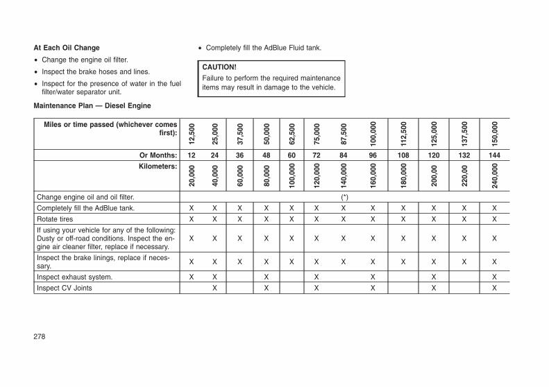
At Each Oil Change
• Change the engine oil filter.
• Inspect the brake hoses and lines.
• Inspect for the presence of water in the fuelfilter/water separator unit.
• Completely fill the AdBlue Fluid tank.
CAUTION!
Failure to perform the required maintenanceitems may result in damage to the vehicle.
Maintenance Plan — Diesel Engine
Miles or time passed (whichever comesfirst):
12,5
00
25,0
00
37,5
00
50,0
00
62,5
00
75,0
00
87,5
00
100,
000
112,
500
125,
000
137,
500
150,
000
Or Months: 12 24 36 48 60 72 84 96 108 120 132 144
Kilometers:
20,0
00
40,0
00
60,0
00
80,0
00
100,
000
120,
000
140,
000
160,
000
180,
000
200,
00
220,
00
240,
000
Change engine oil and oil filter. (*)
Completely fill the AdBlue tank. X X X X X X X X X X X X
Rotate tires X X X X X X X X X X X X
If using your vehicle for any of the following:Dusty or off-road conditions. Inspect the en-gine air cleaner filter, replace if necessary.
X X X X X X X X X X X X
Inspect the brake linings, replace if neces-sary. X X X X X X X X X X X X
Inspect exhaust system. X X X X X X X
Inspect CV Joints X X X X X X
278

Miles or time passed (whichever comesfirst):
12,5
00
25,0
00
37,5
00
50,0
00
62,5
00
75,0
00
87,5
00
100,
000
112,
500
125,
000
137,
500
150,
000
Or Months: 12 24 36 48 60 72 84 96 108 120 132 144
Kilometers:
20,0
00
40,0
00
60,0
00
80,0
00
100,
000
120,
000
140,
000
160,
000
180,
000
200,
00
220,
00
240,
000
Visually inspect condition of: exterior body-work, underbody protection, pipes andhoses (exhaust - fuel system - brakes), rub-ber elements (boots, sleeves, bushings,etc.)
X X X X X X
Inspect the front suspension, tie rod endsand boot seals, replace if necessary. X X X X X X
Change brake fluid every 24 months if usingDOT 4 brake fluid. (**) X X X X X X
Inspect the front and rear axle fluid, changeif using your vehicle for police, taxi, fleet,offroad or frequent trailer towing.
X X X X X X
Replace the fuel filter. X X X X X X
Adjust parking brake on vehicles equippedwith four-wheel disc brakes. X X X X X X
Replace engine air cleaner filter. X X X X X X
Replace air conditioning/cabin air filter X X X X X X X X X X X X
Replace accessory drive belt(s). X
Flush and replace the engine coolant at10 years or 150,000 miles (240,000 km)whichever comes first.
X X
279

Miles or time passed (whichever comesfirst):
12,5
00
25,0
00
37,5
00
50,0
00
62,5
00
75,0
00
87,5
00
100,
000
112,
500
125,
000
137,
500
150,
000
Or Months: 12 24 36 48 60 72 84 96 108 120 132 144
Kilometers:
20,0
00
40,0
00
60,0
00
80,0
00
100,
000
120,
000
140,
000
160,
000
180,
000
200,
00
220,
00
240,
000
Inspect or change the transfer case fluid ifusing your vehicle for any of the following:police, taxi, fleet, or frequent trailer towing.
X X X
Change the transfer case fluid X X X
(*) The actual interval for changing engine oiland replacing the engine oil filter depends onthe vehicle usage conditions, and is signalled bythe warning light or message in the instrumentpanel. In all cases, never exceed 1 year/20,000km. If the car is used mainly for urban driving, orfuel that is not strictly compliant with EuropeanSpecifications EN590 is used, it is advisable tochange the oil and replace the filter every year.
(**) The brake fluid change interval is time basedonly, mileage intervals do not apply.
WARNING!
• You can be badly injured working on oraround a motor vehicle. Do only servicework for which you have the knowledgeand the right equipment. If you have anydoubt about your ability to perform a ser-vice job, take your vehicle to a competentmechanic.
• Failure to properly inspect and maintainyour vehicle could result in a componentmalfunction and effect vehicle handlingand performance. This could cause anaccident.
280

ENGINE COMPARTMENT3.6L Engine
1 — Remote Jump Start Positive Terminal 6 — Air Cleaner Filter2 — Power Distribution Center (Fuses) 7 — Washer Fluid Reservoir3 — Engine Oil Dipstick 8 — Engine Oil Filter Access4 — Engine Oil Fill 9 — Engine Coolant Reservoir5 — Brake Fluid Reservoir 10 — Remote Jump Start Negative Terminal
281

5.7L Engine
1 — Remote Jump Start Positive Terminal 6 — Air Cleaner Filter2 — Power Distribution Center (Fuses) 7 — Washer Fluid Reservoir3 — Engine Oil Dipstick 8 — Coolant Pressure Cap (Radiator)4 — Engine Oil Fill 9 — Engine Coolant Reservoir5 — Brake Fluid Reservoir 10 — Remote Jump Start Negative Terminal
282

3.0L Diesel Engine
1 — Remote Jump Start Positive Terminal 6 — Air Cleaner Filter2 — Power Distribution Center (Fuses) 7 — Washer Fluid Reservoir3 — Engine Oil Dipstick 8 — Coolant Pressure Reservoir4 — Engine Oil Fill 9 — Remote Jump Start Negative Terminal5 — Brake Fluid Reservoir
283

Checking Oil Level — GasolineEngineTo assure proper lubrication of your vehicle’sengine, the engine oil must be maintained at thecorrect level. Check the oil level at regularintervals, such as every fuel stop. The best timeto check the engine oil level is about five min-utes after a fully warmed up engine is shut off.
Checking the oil while the vehicle is on levelground will improve the accuracy of the oil levelreadings. Always maintain the oil level within theSAFE zone on the dipstick. Adding one quart ofoil when the reading is at the bottom of theSAFE zone will result in a reading at the top ofthe safe zone on these engines.
CAUTION!
Overfilling or underfilling the crankcase willcause aeration or loss of oil pressure. Thiscould damage your engine.
Checking Oil Level — Diesel EngineTo assure proper lubrication of your vehicle’sengine, the engine oil must be maintained at thecorrect level. Check the oil level at regularintervals. The best time to check the oil level isbefore starting the engine after it has beenparked overnight. When checking oil after oper-
ating the engine, first ensure the engine is at fulloperating temperature, then wait for five min-utes after engine shutdown to check the oil.
1 — MAX Mark
2 — MIN Mark
Checking the oil while the vehicle is on levelground will improve the accuracy of the oil levelreadings. Add oil only when the level on thedipstick is below the “MIN” mark. The totalcapacity from the MIN mark to the MAX mark is1.7 qts (1.6L).
CAUTION!
Overfilling or underfilling the crankcase willcause oil aeration or loss of oil pressure. Thiscould damage your engine.
NOTE:It is possible for your oil level to be slightlyhigher than a previous check. This would bedue to diesel fuel that may temporarily be inthe crankcase due to operation of the dieselparticulate filter regeneration strategy. Thisfuel will evaporate out under normal opera-tion.
Never operate the engine with oil level below the“MIN” mark or above the upper “MAX” mark.
Adding Washer FluidThe instrument cluster display will indicate whenthe washer fluid level is low. When the sensordetects a low fluid level, the windshield will lighton the vehicle graphic outline and the“WASHER FLUID LOW” message will be dis-played.
The fluid reservoir for the windshield washersand the rear window washer is shared. The fluidreservoir is located in the engine compartment,be sure to check the fluid level at regular inter-vals. Fill the reservoir with windshield washersolvent only (not radiator antifreeze). When re-
Oil Dipstick
284

filling the washer fluid reservoir, take somewasher fluid and apply it to a cloth or towel andwipe clean the wiper blades, this will help bladeperformance. To prevent freeze-up of your wind-shield washer system in cold weather, select asolution or mixture that meets or exceeds thetemperature range of your climate. This ratinginformation can be found on most washer fluidcontainers.
WARNING!
Commercially available windshield washersolvents are flammable. They could igniteand burn you. Care must be exercised whenfilling or working around the washer solution.
Maintenance-Free BatteryYour vehicle is equipped with a maintenance-free battery. You will never have to add water,nor is periodic maintenance required.
WARNING!
• Battery fluid is a corrosive acid solution andcan burn or even blind you. Do not allowbattery fluid to contact your eyes, skin, orclothing. Do not lean over a battery whenattaching clamps. If acid splashes in eyesor on skin, flush the area immediately withlarge amounts of water. Refer to “Jump-Starting Procedure” in “In Case Of Emer-gency” for further information.
• Battery gas is flammable and explosive.Keep flame or sparks away from the bat-tery. Do not use a booster battery or anyother booster source with an output greaterthan 12 Volts. Do not allow cable clamps totouch each other.
• Battery posts, terminals, and related ac-cessories contain lead and lead com-pounds. Wash hands after handling.
CAUTION!
• It is essential when replacing the cables onthe battery that the positive cable is at-tached to the positive post and the nega-tive cable is attached to the negative post.Battery posts are marked positive (+) andnegative (-) and are identified on the bat-tery case. Cable clamps should be tight onthe terminal posts and free of corrosion.
• If a “fast charger” is used while the batteryis in the vehicle, disconnect both vehiclebattery cables before connecting the char-ger to the battery. Do not use a “fastcharger” to provide starting voltage.
DEALER SERVICEYour authorized dealer has the qualified servicepersonnel, special tools, and equipment to per-form all service operations in an expert manner.Service Manuals are available which includedetailed service information for your vehicle.Refer to these Service Manuals before attempt-ing any procedure yourself.
285

NOTE:Intentional tampering with emissions controlsystems may void your warranty and couldresult in civil penalties being assessedagainst you.
WARNING!
You can be badly injured working on oraround a motor vehicle. Only do service workfor which you have the knowledge and theproper equipment. If you have any doubtabout your ability to perform a service job,take your vehicle to a competent mechanic.
Engine OilChange Engine Oil — Gasoline EngineRefer to the “Maintenance Plan” in this sectionfor the proper maintenance intervals.
Change Engine Oil — Diesel EngineRefer to the “Scheduled Servicing” for theproper maintenance intervals.
Gasoline Engine Oil SelectionFor best performance and maximum protectionunder all types of operating conditions, themanufacturer only recommend engine oils thatare API certified and meet the requirements ofFCAMaterial Standard MS-6395, FCA 9.55535-CR1 or ACEA A1/B1 .
Diesel Engine Oil SelectionFor best performance and maximum protectionunder all types of operating conditions, themanufacturer recommends engine oils thatmeet the requirements of FCA Material Stan-dard MS-10902, and that are ACEA E9/E7 orA3/B4 certified and meet the requirements ofFCA LLC.
American Petroleum Institute (API) EngineOil Identification Symbol
This symbolmeans that the oilhas been certifiedby the AmericanPetroleum Institute(API). The manu-facturer only rec-ommends API Cer-tified engine oils.
This symbol certi-fies 0W-20, 5W-20,
0W-30, 5W-30 and 10W-30 engine oils.
CAUTION!
Do not use chemical flushes in your engineoil as the chemicals can damage your en-gine. Such damage is not covered by theNew Vehicle Limited Warranty.
Engine Oil Viscosity – 3.6L EngineSAE 0W-20 engine oil is recommended for alloperating temperatures. This engine oil im-proves low temperature starting and vehicle fueleconomy.
The engine oil filler cap also shows the recom-mended engine oil viscosity for your vehicle. Forinformation on engine oil filler cap location, referto “Engine Compartment” illustration in this sec-tion for further information.
Engine Oil Viscosity – 5.7L EngineSAE 5W-20 engine oil is recommended for alloperating temperatures. This engine oil im-proves low temperature starting and vehicle fueleconomy.
The engine oil filler cap also shows the recom-mended engine oil viscosity for your engine. Forinformation on engine oil filler cap location, referto the “Engine Compartment” illustration in thissection.
NOTE:Vehicles equipped with a 5.7L engine mustuse SAE 5W-20 oil. Failure to do so mayresult in improper operation of the FuelSaver Technology.
286

Engine Oil Viscosity — 3.0L Diesel Engine
CAUTION!
Your vehicle is equipped with an advancedtechnology Diesel Engine and an emissiondevice designed to limit Diesel ParticulateEmissions from being released into the atmo-sphere. The durability of your engine and lifeexpectancy of this diesel particulate filteremission device is highly dependent on theuse of the correct engine oil.
We recommend you use 5W-40 synthetic en-gine oil such as MOPAR that meets FCA Mate-rial Standard MS-10902 and the ACEA E9/E7 orA3/B4 engine oil category is required.
The engine oil filler cap also shows the recom-mended engine oil viscosity for your engine. Forinformation on engine oil filler cap location, referto “Engine Compartment” illustration in this sec-tion for further information.
Synthetic Engine OilsYou may use synthetic engine oils provided therecommended oil quality requirements are met,and the recommended maintenance intervalsfor oil and filter changes are followed.
Synthetic engine oils which do not have both theengine oil certification mark and the correct SAEviscosity grade number should not be used.
Materials Added To Engine OilThe manufacturer strongly recommends againstthe addition of any additives (other than leakdetection dyes) to the engine oil. Engine oil is anengineered product and its performance may beimpaired by supplemental additives.
Disposing Of Used Engine Oil And OilFiltersCare should be taken in disposing of usedengine oil and oil filters from your vehicle. Usedoil and oil filters, indiscriminately discarded, canpresent a problem to the environment. Contactyour authorized dealer, service station or gov-ernmental agency for advice on how and whereused oil and oil filters can be safely discarded inyour area.
Engine Oil FilterThe engine oil filter should be replaced with anew filter at every engine oil change.
Engine Oil Filter Selection
This manufacturer’s engines have a full-flowtype disposable oil filter. Use a filter of this typefor replacement. The quality of replacementfilters varies considerably. Only high quality fil-ters should be used to assure most efficientservice. MOPAR engine oil filters are high qual-ity oil filters and are recommended.
Engine Air Cleaner FilterRefer to the “Maintenance Plan” in this sectionfor the proper maintenance intervals.
NOTE:Be sure to follow the “Severe Duty Condi-tions” maintenance interval if applicable.
WARNING!
The air induction system (air cleaner, hoses,etc.) can provide a measure of protection inthe case of engine backfire. Do not removethe air induction system (air cleaner, hoses,etc.) unless such removal is necessary forrepair or maintenance. Make sure that noone is near the engine compartment beforestarting the vehicle with the air inductionsystem (air cleaner, hoses, etc.) removed.Failure to do so can result in serious personalinjury.
Engine Air Cleaner Filter Selection
The quality of replacement engine air cleanerfilters varies considerably. Only high quality fil-ters should be used to assure most efficientservice. MOPAR engine air cleaner filters are ahigh quality filter and are recommended.
287

Air Cleaner Filter Inspection andReplacement — Gasoline EngineInspect engine air cleaner filter for dirt and ordebris, if you find evidence of either dirt or debrisyou should change your air cleaner filter.
Engine Air Cleaner Filter Removal
1. Release the spring clips from the air cleanercover.
2. Lift the air cleaner cover to access the aircleaner filter.
3. Remove the air cleaner filter element fromthe housing assembly.
Engine Air Cleaner Filter Installation
NOTE:Inspect and clean the housing if dirt ordebris is present before replacing the airfilter element.
1. Install the air cleaner filter element into thehousing assembly with the air cleaner filterinspection surface facing downward.
2. Install the air cleaner cover onto the housingassembly locating tabs.
3. Latch the spring clips and lock the air cleanercover to the housing assembly.
Air Cleaner Filter Cover
1 — Clean Air Hose Clamp2 — Air Hose3 — Spring Clips
Open Air Cleaner Filter Assembly
1 — Air Cleaner Cover2 — Air Cleaner Filter
Air Cleaner Filter
1 — Air Cleaner Filter2 — Air Cleaner Filter Inspection Surface
288

Air Cleaner Filter Inspection andReplacement — Diesel EngineInspect engine air cleaner filter for dirt and ordebris, if you find evidence of either dirt or debrisyou should change your air cleaner filter.
Engine Air Cleaner Filter Removal
1. Release the spring clips from the air cleanercover.
2. Lift the air cleaner cover to access the aircleaner filter.
3. Remove the air cleaner filter element fromthe housing assembly.
Engine Air Cleaner Filter Installation
NOTE:Inspect and clean the housing if dirt ordebris is present before replacing the airfilter element.
1. Install the air cleaner filter element into thehousing assembly with the air cleaner filterinspection surface facing downward.
2. Install the air cleaner cover onto the housingassembly locating tabs.
3. Latch the spring clips and lock the air cleanercover to the housing assembly.
Air Cleaner Filter Cover
1 — Spring Clips2 — Air Cleaner Filter Cover
Open Air Cleaner Filter Assembly
1 — Air Cleaner Filter2 — Air Cleaner Cover
Air Cleaner Filter
1 — Air Cleaner Filter Inspection Surface2 — Air Cleaner Filter
289

Air Conditioner MaintenanceFor best possible performance, your air condi-tioner should be checked and serviced by anauthorized dealer at the start of each warmseason. This service should include cleaning ofthe condenser fins and a performance test.Drive belt tension should also be checked at thistime.
WARNING!
• Use only refrigerants and compressor lu-bricants approved by the manufacturer foryour air conditioning system. Some unap-proved refrigerants are flammable and canexplode, injuring you. Other unapprovedrefrigerants or lubricants can cause thesystem to fail, requiring costly repairs. Re-fer to Warranty Information Book, for fur-ther warranty information.
• The air conditioning system contains refrig-erant under high pressure. To avoid risk ofpersonal injury or damage to the system,adding refrigerant or any repair requiringlines to be disconnected should be done byan experienced technician.
CAUTION!
Do not use chemical flushes in your airconditioning system as the chemicals candamage your air conditioning components.Such damage is not covered by the NewVehicle Limited Warranty.
Refrigerant Recovery And Recycling R134a— If EquippedR-134a Air Conditioning Refrigerant is a hydro-fluorocarbon (HFC) that is an ozone-friendlysubstance. The manufacturer recommends thatair conditioning service be performed by anauthorized dealer or other service facilities usingrecovery and recycling equipment.
NOTE:Use only manufacturer approved A/C systemPAG compressor oil and refrigerants.
Refrigerant Recovery And Recycling —R–1234yfR–1234yf Air Conditioning Refrigerant is a hy-drofluoroolefin (HFO) that is endorsed by theEnvironmental Protection Agency and is anozone-friendly substance with a low global-warming potential. The manufacturer recom-mends that air conditioning service be per-formed by authorized dealer using recovery andrecycling equipment.
NOTE:Use only manufacturer approved A/C systemPAG compressor oil, and refrigerants.
Air Conditioning Filter Replacement (A/CAir Filter)Refer to “Scheduled Servicing” in this section forthe proper maintenance intervals.
WARNING!
Do not remove the cabin air filter while thevehicle is running, or while the ignition is intheACC or ON/RUNmode. With the cabin airfilter removed and the blower operating, theblower can contact hands and may propel dirtand debris into your eyes, resulting in per-sonal injury.
The A/C air filter is located in the fresh air inletbehind the glove compartment. Perform thefollowing procedure to replace the filter:
1. Open the glove compartment and remove allcontents.
290

2. There are glove compartment travel stops onboth sides of the glove compartment door,partially close the glove compartment doorand push inward to release the glove com-partment travel stop on one side and repeatthis procedure for the opposite side.
3. Pull the right hand side of the glove compart-ment door toward the rear of the vehicle todisengage the glove compartment door fromits hinges.
NOTE:When disengaging the glove compartmentdoor from its hinges, there will be someresistance.
4. With the glove compartment door loose, re-move the glove compartment tension tetherand tether clip by sliding the clip toward theface of the glove compartment door andlifting the clip out of glove compartment door.
5. Remove the filter cover by disengaging theretaining tab and mid way snap that securesthe filter cover to the HVAC housing. Disen-
gage the mid way snap by pulling the dooroutward. Unhinge the filter cover on the rightside to fully remove the cover.
6. Remove the A/C air filter by pulling it straightout of the housing.
7. Install the A/C air filter with the arrow on thefilter pointing toward the floor. When install-ing the filter cover, make sure the retainingtabs fully engage the cover.
Glove Compartment
1 — Glove Compartment Travel Stops2 — Glove Compartment Tension Tether3 — Glove Compartment Door
Right Side Of Glove Compartment
1 — Glove Compartment Tension Tether2 — Glove Compartment Door
A/C Air Filter Cover
1 — Retaining Tab2 — Mid Way Snap3 — Filter Cover Hinge
291

CAUTION!
The cabin air filter is identified with an arrowto indicate airflow direction through the filter.Failure to properly install the filter will result inthe need to replace it more often.
8. Reinstall the glove compartment door on theglove compartment door hinge and reattachthe glove compartment tension tether byinserting the tether clip in the glove compart-ment and sliding the clip away from the faceof the glove compartment door.
9. Push the door to the near closed position toreengage the glove compartment travelstops.
NOTE:Ensure the glove compartment door hingesand glove compartment travel stops are fullyengaged.
Accessory Drive Belt Inspection
WARNING!
• Do not attempt to inspect an accessorydrive belt with vehicle running.
• When working near the radiator coolingfan, disconnect the fan motor lead. The fanis temperature controlled and can start atany time regardless of ignition mode. Youcould be injured by the moving fan blades.
• You can be badly injured working on oraround a motor vehicle. Only do servicework for which you have the knowledgeand the proper equipment. If you have anydoubt about your ability to perform a ser-vice job, take your vehicle to a competentmechanic.
When inspecting accessory drive belts, smallcracks that run across ribbed surface of beltfrom rib to rib, are considered normal. These arenot a reason to replace belt. However, cracksrunning along a rib (not across) are not normal.Any belt with cracks running along a rib must bereplaced. Also have the belt replaced if it hasexcessive wear, frayed cords or severe glazing.
Conditions that would require replacement:
• Rib chunking (one or more ribs has separatedfrom belt body)
• Rib or belt wear
• Longitudinal belt cracking (cracks betweentwo ribs)
• Belt slips
• “Groove jumping" (belt does not maintaincorrect position on pulley)
• Belt broken (note: identify and correct prob-lem before new belt is installed)
• Noise (objectionable squeal, squeak, orrumble is heard or felt while drive belt is inoperation)
Accessory Belt (Serpentine Belt)
292

Some conditions can be caused by a faultycomponent such as a belt pulley. Belt pulleysshould be carefully inspected for damage andproper alignment.
Belt replacement on some models requires theuse of special tools, we recommend having yourvehicle serviced at an authorized dealer.
Draining Fuel/Water Separator Filter— Diesel EngineThe fuel filter/water separator housing is locatedon the left side of the vehicle in front of the fueltank. The best access to this water drain valve isfrom under the vehicle.
CAUTION!
• Do not drain the fuel/water separator filterwhen the engine is running.
• Diesel fuel will damage blacktop pavingsurfaces. Drain the filter into an appropriatecontainer.
If water is detected in the water separator whilethe engine is running, or while the ignition switchis in the ON position, the “Water In Fuel IndicatorLight” will illuminate and an audible chime will beheard. At this point you should stop the engineand drain the water from the filter housing.
1 — Fuel Filter Access2 — Water in Fuel Drain
Within 10 minutes of vehicle shutdown, turn thefilter drain valve (located on the bottom of thefilter housing) counterclockwise to drain fuel/water; allow the accumulated water to drain.Leave the drain valve open until all water andcontaminants have been removed. When clearfuel is visible, close the drain valve by turning itclockwise.
Upon proper draining of the water from fuel filterassembly, the “Water In Fuel Indicator Light” willremain illuminated for approximately 10 sec-onds. If the water was drained while the enginewas running, the “Water In Fuel Indicator Light”may remain on for approximately three minutes.
NOTE:Care should be taken in disposing of usedfluids from your vehicle. Used fluids, indis-criminately discarded, can present a prob-lem to the environment. Contact an autho-rized dealer, service station, or governmentagency for advice on recycling programsand for where used fluids and filters can beproperly disposed of in your area.
If more than two ounces or 60 milliliters of fuelhave been drained, follow the directions for“Priming If The Engine Has Run Out Of Fuel.”
Underbody Mounted Fuel FilterReplacement — Diesel EngineNOTE:Using a fuel filter that does not meet themanufacturer’s filtration and water separat-ing requirements can severely impact fuelsystem life and reliability.
CAUTION!
• Diesel fuel will damage blacktop pavingsurfaces. Drain the filter into an appropriatecontainer.
(Continued)
Fuel Filter Assembly
293

CAUTION! (Continued)
• Do not prefill the fuel filter when installing anew fuel filter. There is a possibility debriscould be introduced into the fuel filter dur-ing this action. It is best to install the filterdry and allow the in-tank lift pump to primethe fuel system.
1 — Fuel Filter Access
2 — Water in Fuel Drain
1. Ensure engine is turned off.
2. Place drain pan under the fuel filter assem-bly.
3. Open the water drain valve, and let anyaccumulated water and fuel drain.
4. Close the water drain valve.
5. Wipe clean the underside of the filter housingto prevent contamination from entering fuelsystem during service.
6. Remove using a socket. Rotate counter-clockwise for removal.
7. Remove the used filter cartridge from thehousing and dispose of according to yourlocal regulations.
8. Wipe clean the sealing surfaces of the lid andhousing.
CAUTION!
Take care when handling the new fuel filter toprevent contamination from entering the fuelsystem.
9. Lubricate o-ring on new filter with clean en-gine oil.
10. Install the cartridge into the housing withclockwise rotation, use a socket to tighten.
11. Repeat steps 5 through 10 to service sec-ond fuel filter in assembly.
12. After engine start, verify the filters do notleak.
Priming If The Engine Has Run OutOf Fuel — Diesel Engine
WARNING!
Do not open the high pressure fuel systemwith the engine running. Engine operationcauses high fuel pressure. High pressure fuelspray can cause serious injury or death.
1. Add a substantial amount of fuel to the tank,approximately 2 to 5 gal (8L to 19L).
2. Press ignition switch twice without your footon brake to put vehicle in Run position. Thiswill activate the in tank fuel pump for approxi-mately 30 seconds. Repeat this processtwice.
3. Start the engine using the “Normal Starting”procedure. Refer to “Starting Procedures” in“Starting and Operating” for further informa-tion.
Fuel Filter Assembly
294

CAUTION!
The starter motor will engage for approxi-mately 30 seconds at a time. Allow twominutes between cranking intervals.
NOTE:The engine may run rough until the air isforced from all the fuel lines.
WARNING!
Do not use alcohol or gasoline as a fuelblending agent. They can be unstable undercertain conditions and be hazardous or ex-plosive when mixed with diesel fuel.
CAUTION!
Due to lack of lubricants in alcohol or gaso-line, the use of these fuels can cause dam-age to the fuel system.
NOTE:
• Use of biodiesel mixture in excess of 20%can negatively impact the fuel filter’s abil-ity to separate water from the fuel, result-ing in high pressure fuel system corrosionor damage.
• In addition, commercially available fueladditives are not necessary for the properoperation of your diesel engine.
• For extreme cold conditions, �Mopar Pre-mium Diesel Fuel Treatment� is recom-mended to assist with cold starting.
Intervention Regeneration Strategy— Message Process Flow (DieselEngine)This engine meets all required diesel engineemissions standards. To achieve these emis-sions standards, your vehicle is equipped with astate-of-the-art engine and exhaust system.These systems are seamlessly integrated intoyour vehicle and managed by the PowertrainControl Module (PCM). The PCM manages en-gine combustion to allow the exhaust system’scatalyst to trap and burn Particulate Matter (PM)pollutants, with no input or interaction on yourpart.
Additionally, your vehicle has the ability to alertyou to additional maintenance required on yourvehicle or engine.
Refer to “Instrument Cluster Display” in “GettingTo Know Your Instrument Panel” for furtherinformation.
WARNING!
A hot exhaust system can start a fire if youpark over materials that can burn. Suchmaterials might be grass or leaves cominginto contact with your exhaust system. Do notpark or operate your vehicle in areas whereyour exhaust system can contact anythingthat can burn.
Diesel Exhaust Fluid/AdBlueAdblue sometimes known simply by the name ofits active component, UREA—is a key compo-nent of selective catalytic reduction (SCR) sys-tems, which help diesel vehicles meet stringentemission regulations. DEF is a liquid reducingagent that reacts with engine exhaust in thepresence of a catalyst to convert smog-formingnitrogen oxides (NOx) into harmless nitrogenand water vapor.
Refer to “Fluids And Lubricants” in “TechnicalSpecifications” for further information.
Body LubricationLocks and all body pivot points, including suchitems as seat tracks, door hinge pivot points androllers, liftgate, tailgate, decklid, sliding doorsand hood hinges, should be lubricated periodi-cally with a lithium based grease, such asMOPAR Spray White Lube to assure quiet, easy
295

operation and to protect against rust and wear.Prior to the application of any lubricant, the partsconcerned should be wiped clean to removedust and grit; after lubricating excess oil andgrease should be removed. Particular attentionshould also be given to hood latching compo-nents to ensure proper function. When perform-ing other underhood services, the hood latch,release mechanism and safety catch should becleaned and lubricated.
The external lock cylinders should be lubricatedtwice a year, preferably in the Fall and Spring.Apply a small amount of a high quality lubricant,such as MOPAR Lock Cylinder Lubricant di-rectly into the lock cylinder.
Windshield Wiper BladesClean the rubber edges of the wiper blades andthe windshield periodically with a sponge or softcloth and a mild nonabrasive cleaner. This willremove accumulations of salt or road film.
Operation of the wipers on dry glass for longperiods may cause deterioration of the wiperblades. Always use washer fluid when using thewipers to remove salt or dirt from a dry wind-shield.
Avoid using the wiper blades to remove frost orice from the windshield. Keep the blade rubberout of contact with petroleum products such asengine oil, gasoline, etc.
NOTE:Life expectancy of wiper blades varies de-pending on geographical area and frequencyof use. Poor performance of blades may bepresent with chattering, marks, water linesor wet spots. If any of these conditions arepresent, clean the wiper blades or replace asnecessary.
The wiper blades and wiper arms should beinspected periodically, not just when wiper per-formance problems are experienced. This in-spection should include the following points:
• Wear Or Uneven Edges
• Foreign Material
• Hardening Or Cracking
• Deformation Or Fatigue
If a wiper blade or wiper arm is damaged,replace the affected wiper arm or blade with anew unit. Do not attempt to repair a wiper arm orblade that is damaged.
Front Wiper Blade Removal/Installation
CAUTION!
Do not allow the wiper arm to spring backagainst the glass without the wiper blade inplace or the glass may be damaged.
1. Lift the wiper arm to raise the wiper blade offof the glass, until the wiper arm is in the fullup position.
2. To disengage the wiper blade from the wiperarm, flip up the release tab on the wiperblade and while holding the wiper arm withone hand, slide the wiper blade down to-wards the base of the wiper arm.
Wiper Blade With Release Tab In LockedPosition
1 — Wiper2 — Release Tab3 — Wiper Arm
296

3. With the wiper blade disengaged, removethe wiper blade from the wiper arm by hold-ing the wiper arm with one hand and sepa-rating the wiper blade from the wiper armwith the other hand (move the wiper bladetoward the right side of the vehicle to sepa-rate the wiper blade from the wiper arm).
4. Gently lower the wiper arm onto the glass.Installing The Front Wipers
1. Lift the wiper arm off of the glass, until thewiper arm is in the full up position.
2. Position the wiper blade near the hook on thetip of the wiper arm with the wiper release tabopen and the blade side of the wiper facingup and away from the windshield.
3. Insert the hook on the tip of the arm throughthe opening in the wiper blade under therelease tab.
4. Slide the wiper blade up into the hook on thewiper arm and rotate the wiper blade until it isflush against the wiper arm. Fold down thelatch release tab and snap it into its lockedposition. Latch engagement will be accom-panied by an audible click.
5. Gently lower the wiper blade onto the glass.Wiper Blade With Release Tab In UnlockedPosition
1 — Wiper Blade2 — Release Tab3 — Wiper Arm
Wiper Blade Removed From Wiper Arm
1 — Wiper Blade2 — Wiper Arm3 — Release Tab
297

Rear Wiper Blade Removal/Installation
1. Lift the rear wiper arm pivot cap away fromthe glass to allow the rear wiper blade to beraised off of the glass.
NOTE:The rear wiper arm cannot be fully raised offthe glass unless the wiper arm pivot cap isunsnapped first. Attempting to fully raise therear wiper arm without unsnapping the wiperarm pivot cap may damage the vehicle.
2. Lift the rear wiper arm fully off the glass.
3. To remove the wiper blade from the wiperarm, grasp the bottom end of the wiper bladenearest to wiper arm with your right hand.With your left hand hold the wiper arm as youpull the wiper blade away from the wiper armpast its stop far enough to unsnap the wiperblade pivot pin from the receptacle on theend of the wiper arm.
NOTE:Resistance will be accompanied by an au-dible snap.
4. Still grasping the bottom end of the wiperblade, move the wiper blade upward andaway from the wiper arm to disengage.
5. Gently lower the tip of the wiper arm onto theglass.
Wiper Pivot Cap In Unlocked Position
1 — Wiper Arm Pivot Cap2 — Wiper Arm
Wiper Blade In Folded Out Position
1 — Wiper Arm Pivot Cap2 — Wiper Arm3 — Wiper Blade
Wiper Blade Removed From Wiper Arm
1 — Wiper Blade2 — Wiper Blade Pivot Pin3 — Wiper Arm4 — Wiper Arm Receptacle
298

Installing The Rear Wiper
1. Lift the rear wiper arm pivot cap away fromthe glass to allow the rear wiper blade to beraised off of the glass.
NOTE:The rear wiper arm cannot be fully raised offthe glass unless the wiper arm pivot cap isunsnapped first. Attempting to fully raise therear wiper arm without unsnapping the wiperarm pivot cap may damage the vehicle.
2. Lift the rear wiper arm fully off the glass.
3. Insert the wiper blade pivot pin into theopening on the end of the wiper arm. Grabthe bottom end of the wiper arm with onehand, and press the wiper blade flush withthe wiper arm until it snaps into place.
4. Lower the wiper blade onto the glass andsnap the wiper arm pivot cap back into place.
Exhaust SystemThe best protection against carbon monoxideentry into the vehicle body is a properly main-tained engine exhaust system.
If you notice a change in the sound of theexhaust system; or if the exhaust fumes can bedetected inside the vehicle; or when the under-side or rear of the vehicle is damaged; have an
authorized technician inspect the complete ex-haust system and adjacent body areas for bro-ken, damaged, deteriorated, or mispositionedparts. Open seams or loose connections couldpermit exhaust fumes to seep into the passen-ger compartment. In addition, have the exhaustsystem inspected each time the vehicle is raisedfor lubrication or oil change. Replace as re-quired.
WARNING!
• Exhaust gases can injure or kill. Theycontain carbon monoxide (CO), which iscolorless and odorless. Breathing it canmake you unconscious and can eventuallypoison you. To avoid breathing CO, refer to“Safety Tips” in “Safety” for further informa-tion.
• A hot exhaust system can start a fire if youpark over materials that can burn. Suchmaterials might be grass or leaves cominginto contact with your exhaust system. Donot park or operate your vehicle in areaswhere your exhaust system can contactanything that can burn.
CAUTION!
• The catalytic converter requires the use ofunleaded fuel only. Leaded gasoline willdestroy the effectiveness of the catalyst asan emissions control device and may seri-ously reduce engine performance andcause serious damage to the engine.
• Damage to the catalytic converter can re-sult if your vehicle is not kept in properoperating condition. In the event of enginemalfunction, particularly involving enginemisfire or other apparent loss of perfor-mance, have your vehicle servicedpromptly. Continued operation of your ve-hicle with a severe malfunction couldcause the converter to overheat, resultingin possible damage to the converter andvehicle.
Under normal operating conditions, the catalyticconverter will not require maintenance. How-ever, it is important to keep the engine properlytuned to assure proper catalyst operation andprevent possible catalyst damage.
NOTE:Intentional tampering with emissions controlsystems can result in civil penalties beingassessed against you.
299

In unusual situations involving grossly malfunc-tioning engine operation, a scorching odor maysuggest severe and abnormal catalyst overheat-ing. If this occurs, stop the vehicle, turn off theengine and allow it to cool. Service, including atune-up to manufacturer’s specifications, shouldbe obtained immediately.
To minimize the possibility of catalytic converterdamage:
• Do not shut off the engine or interrupt theignition, when the transmission is in gear andthe vehicle is in motion.
• Do not try to start the engine by pushing ortowing the vehicle.
• Do not idle the engine with any spark plugwires disconnected or removed, such aswhen diagnostic testing, or for prolongedperiods during very rough idle or malfunction-ing operating conditions.
Cooling System
WARNING!
• Turn vehicle off and disconnect the fanmotor lead before working near the radiatorcooling fan.
(Continued)
WARNING! (Continued)
• You or others can be badly burned by hotengine coolant (antifreeze) or steam fromyour radiator. If you see or hear steamcoming from under the hood, do not openthe hood until the radiator has had time tocool. Never open a cooling system pres-sure cap when the radiator or coolant bottleis hot.
• Keep hands, tools, clothing, and jewelryaway from the radiator cooling fan whenthe hood is raised. The fan starts automati-cally and may start at any time, whether theengine is running or not.
• When working near the radiator coolingfan, disconnect the fan motor lead or turnthe ignition to the OFF mode. The fan istemperature controlled and can start at anytime the ignition is in the ON mode.
• You or others can be badly burned by hotengine coolant (antifreeze) or steam fromyour radiator. If you see or hear steamcoming from under the hood, do not openthe hood until the radiator has had time tocool. Never try to open a cooling systempressure cap when the radiator is hot.
Engine Coolant ChecksCheck the engine coolant (antifreeze) protectionevery 12 months (before the onset of freezingweather, where applicable). If the engine cool-ant (antifreeze) is dirty, the system should bedrained, flushed, and refilled with fresh OATcoolant (conforming to MS.90032) by an autho-rized dealer. Check the front of the A/C con-denser for any accumulation of bugs, leaves,etc. If dirty, clean by gently spraying water froma garden hose vertically down the face of thecondenser.
Check the engine cooling system hoses forbrittle rubber, cracking, tears, cuts, and tight-ness of the connection at the coolant recoverybottle and radiator. Inspect the entire system forleaks. DO NOT REMOVE THE COOLANTPRESSURE CAP WHEN THE COOLING SYS-TEM IS HOT.
Cooling System — Drain, Flush And Refill
NOTE:Some vehicles require special tools to addcoolant properly. Failure to fill these systemsproperly could lead to severe internal enginedamage. If any coolant is needed to beadded to the system please contact yourlocal authorized dealer.If the engine coolant (antifreeze) is dirty orcontains visible sediment, have an authorized
300

dealer clean and flush with OAT coolant (anti-freeze) (conforming to MS.90032).
Refer to the “Maintenance Plan” in this sectionfor the proper maintenance intervals.
Selection Of CoolantRefer to “Fluids And Lubricants” in “TechnicalSpecifications” for further information.
CAUTION!
• Mixing of engine coolant (antifreeze) otherthan specified Organic Additive Technology(OAT) engine coolant (antifreeze), may re-sult in engine damage and may decreasecorrosion protection. Organic AdditiveTechnology (OAT) engine coolant is differ-ent and should not be mixed with HybridOrganic Additive Technology (HOAT) en-gine coolant (antifreeze) or any “globallycompatible” coolant (antifreeze). If a non-OAT engine coolant (antifreeze) is intro-duced into the cooling system in an emer-gency, the cooling system will need to bedrained, flushed, and refilled with freshOAT coolant (conforming to MS.90032), byan authorized dealer as soon as possible.
(Continued)
CAUTION! (Continued)
• Do not use water alone or alcohol-basedengine coolant (antifreeze) products. Donot use additional rust inhibitors or antirustproducts, as they may not be compatiblewith the radiator engine coolant and mayplug the radiator.
• This vehicle has not been designed for usewith propylene glycol-based engine cool-ant (antifreeze). Use of propylene glycol-based engine coolant (antifreeze) is notrecommended.
Adding CoolantYour vehicle has been built with an improvedengine coolant (OAT coolant conforming toMS.90032) that allows extended maintenanceintervals. This engine coolant (antifreeze) canbe used up to ten years or 150,000 miles(240,000 km) before replacement. To preventreducing this extended maintenance period, it isimportant that you use the same engine coolant(OAT coolant conforming to MS.90032) through-out the life of your vehicle.
Please review these recommendations for usingOrganic Additive Technology (OAT) engine cool-ant (antifreeze) that meets the requirements ofFCA Material Standard MS.90032. When add-ing engine coolant (antifreeze):
• We recommend using MOPAR Antifreeze/Coolant 10 Year/150,000 Mile (240,000 km)Formula OAT (Organic Additive Technology)that meets the requirements of FCA MaterialStandard MS.90032.
• Mix a minimum solution of 50% OAT enginecoolant that meets the requirements of FCAMaterial Standard MS.90032 and distilled wa-ter. Use higher concentrations (not to exceed70%) if temperatures below −34°F (−37°C)are anticipated.
• Use only high purity water such as distilled ordeionized water when mixing the water/engine coolant (antifreeze) solution. The useof lower quality water will reduce the amountof corrosion protection in the engine coolingsystem.
Please note that it is the owner’s responsibilityto maintain the proper level of protection againstfreezing according to the temperatures occur-ring in the area where the vehicle is operated.
NOTE:
• Some vehicles require special tools to addcoolant properly. Failure to fill these sys-tems properly could lead to severe inter-nal engine damage. If any coolant isneeded to be added to the system, pleasecontact your local authorized dealer.
301

• Mixing engine coolant (antifreeze) types isnot recommended and can result in cool-ing system damage. If HOAT and OATcoolant are mixed in an emergency, have aauthorized dealer drain, flush, and refillwith OAT coolant (conforming toMS.90032) as soon as possible.
Cooling System Pressure CapThe cap must be fully tightened to prevent lossof engine coolant (antifreeze), and to ensurethat engine coolant (antifreeze) will return to theradiator from the coolant recovery tank.
The cap should be inspected and cleaned ifthere is any accumulation of foreign material onthe sealing surfaces.
WARNING!
• Do not open hot engine cooling system.Never add engine coolant (antifreeze)when the engine is overheated. Do notloosen or remove the cap to cool an over-heated engine. Heat causes pressure tobuild up in the cooling system. To preventscalding or injury, do not remove the pres-sure cap while the system is hot or underpressure.
(Continued)
WARNING! (Continued)
• Do not use a pressure cap other than theone specified for your vehicle. Personalinjury or engine damage may result.
Disposal Of Used Engine CoolantUsed ethylene glycol-based engine coolant (an-tifreeze) is a regulated substance requiringproper disposal. Check with your local authori-ties to determine the disposal rules for yourcommunity. To prevent ingestion by animals orchildren, do not store ethylene glycol-basedengine coolant in open containers or allow it toremain in puddles on the ground. If ingested bya child or pet, seek emergency assistance im-mediately. Clean up any ground spills immedi-ately.
Coolant LevelThe coolant bottle provides a quick visualmethod for determining that the coolant level isadequate. With the engine OFF and cold, thelevel of the engine coolant (antifreeze) in thebottle should be between the ranges indicatedon the bottle.
The radiator normally remains completely full,so there is no need to remove the radiator/coolant pressure cap unless checking for enginecoolant (antifreeze) freeze point or replacingcoolant. Advise your service attendant of this. As
long as the engine operating temperature issatisfactory, the coolant bottle need only bechecked once a month.
When additional engine coolant (antifreeze) isneeded to maintain the proper level, only OATcoolant that meets the requirements of FCAMaterial Standard MS.90032 should be addedto the coolant bottle. Do not overfill.
Points To Remember
NOTE:When the vehicle is stopped after a fewmiles/kilometers of operation, you may ob-serve vapor coming from the front of theengine compartment. This is normally a re-sult of moisture from rain, snow, or highhumidity accumulating on the radiator andbeing vaporized when the thermostat opens,allowing hot engine coolant (antifreeze) toenter the radiator.If an examination of your engine compartmentshows no evidence of radiator or hose leaks, thevehicle may be safely driven. The vapor willsoon dissipate.
• Do not overfill the coolant expansion bottle.
• Check the coolant freeze point in the radiatorand in the coolant expansion bottle. If enginecoolant (antifreeze) needs to be added, the
302

contents of the coolant expansion bottle mustalso be protected against freezing.
• If frequent engine coolant (antifreeze) addi-tions are required, the cooling system shouldbe pressure tested for leaks.
• Maintain engine coolant (antifreeze) concen-tration at a minimum of 50% OAT coolant(conforming to MS.90032) and distilled waterfor proper corrosion protection of your enginewhich contains aluminum components.
• Make sure that the coolant expansion bottleoverflow hoses are not kinked or obstructed.
• Keep the front of the radiator clean. If yourvehicle is equipped with air conditioning,keep the front of the condenser clean.
• Do not change the thermostat for Summer orWinter operation. If replacement is ever nec-essary, install ONLY the correct type thermo-stat. Other designs may result in unsatisfac-tory engine coolant (antifreeze) performance,poor gas mileage, and increased emissions.
Brake SystemIn order to assure brake system performance,all brake system components should be in-spected periodically. Refer to the “MaintenancePlan” in this section for the proper maintenanceintervals.
WARNING!
Riding the brakes can lead to brake failureand possibly a collision. Driving with your footresting or riding on the brake pedal can resultin abnormally high brake temperatures, ex-cessive lining wear, and possible brake dam-age. You would not have your full brakingcapacity in an emergency.
Fluid Level Check — Brake Master CylinderThe fluid level of the master cylinder should bechecked whenever the vehicle is serviced, orimmediately if the brake system warning light ison. If necessary, add fluid to bring level to the fullmark on the side of the reservoir of the brakemaster cylinder. Be sure to clean the top of themaster cylinder area before removing cap. Withdisc brakes, fluid level can be expected to fall asthe brake pads wear. Brake fluid level should bechecked when pads are replaced. If the brakefluid is abnormally low, check system for leaks.
Refer to “Fluids And Lubricants” in “TechnicalSpecifications” for further information.
WARNING!
• Use only manufacturer’s recommendedbrake fluid. Refer to “Fluids And Lubri-cants” in “Technical Specifications” for fur-ther information. Using the wrong type ofbrake fluid can severely damage yourbrake system and/or impair its perfor-mance. The proper type of brake fluid foryour vehicle is also identified on the origi-nal factory installed hydraulic master cylin-der reservoir.
• To avoid contamination from foreign matteror moisture, use only new brake fluid orfluid that has been in a tightly closed con-tainer. Keep the master cylinder reservoircap secured at all times. Brake fluid in aopen container absorbs moisture from theair resulting in a lower boiling point. Thismay cause it to boil unexpectedly duringhard or prolonged braking, resulting in sud-den brake failure. This could result in acollision.
(Continued)
303

WARNING! (Continued)
• Overfilling the brake fluid reservoir canresult in spilling brake fluid on hot engineparts, causing the brake fluid to catch fire.Brake fluid can also damage painted andvinyl surfaces, care should be taken toavoid its contact with these surfaces.
• Do not allow petroleum based fluid to con-taminate the brake fluid. Brake seal com-ponents could be damaged, causing partialor complete brake failure. This could resultin a collision.
Automatic TransmissionSelection Of LubricantIt is important to use the proper transmissionfluid to ensure optimum transmission perfor-mance and life. Use only the manufacturer’sspecified transmission fluid. Refer to “Fluids AndLubricants” in “Technical Specifications” for fluidspecifications. It is important to maintain thetransmission fluid at the correct level using therecommended fluid.
NOTE:No chemical flushes should be used in anytransmission; only the approved lubricantshould be used.
CAUTION!
Using a transmission fluid other than themanufacturer’s recommended fluid maycause deterioration in transmission shift qual-ity and/or torque converter shudder. Refer to“Fluids And Lubricants” in “Technical Specifi-cations” for fluid specifications.
Special AdditivesThe manufacturer strongly recommends againstusing any special additives in the transmission.Automatic Transmission Fluid (ATF) is an engi-neered product and its performance may beimpaired by supplemental additives. Therefore,do not add any fluid additives to the transmis-sion. Avoid using transmission sealers as theymay adversely affect seals.
CAUTION!
Do not use chemical flushes in your trans-mission as the chemicals can damage yourtransmission components. Such damage isnot covered by the New Vehicle LimitedWarranty.
Fluid Level CheckThe fluid level is preset at the factory and doesnot require adjustment under normal operatingconditions. Routine fluid level checks are not
required; therefore the transmission has no dip-stick. Your authorized dealer can check yourtransmission fluid level using special servicetools. If you notice fluid leakage or transmissionmalfunction, visit your authorized dealer imme-diately to have the transmission fluid levelchecked. Operating the vehicle with an improperfluid level can cause severe transmission dam-age.
CAUTION!
If a transmission fluid leak occurs, visit yourauthorized dealer immediately. Severe trans-mission damage may occur. Your authorizeddealer has the proper tools to adjust the fluidlevel accurately.
Fluid And Filter ChangesUnder normal operating conditions, the fluidinstalled at the factory will provide satisfactorylubrication for the life of the vehicle.
Routine fluid and filter changes are not required.However, change the fluid and filter if the fluidbecomes contaminated (with water, etc.), or ifthe transmission is disassembled for any rea-son.
Front/Rear Axle FluidFor normal service, periodic fluid level checksare not required. When the vehicle is serviced
304

for other reasons the exterior surfaces of theaxle assembly should be inspected. If gear oilleakage is suspected inspect the fluid level.Refer to “Fluids And Lubricants” in “TechnicalSpecifications” for further information.
Front Axle Fluid Level CheckThe front axle oil level needs to be no lower than1/8 in (3 mm) below the bottom of the fill hole.
The front axle fill and drain plugs should betightened to 22 to 29 ft lbs (30 to 40 N·m).
CAUTION!
Do not overtighten the plugs as it coulddamage them and cause them to leak.
Rear Axle Fluid Level CheckThe rear axle oil level needs to be no lower than1/8 in (3 mm) below the bottom of the fill hole.
The rear axle fill and drain plugs should betightened to 22 to 29 ft lbs (30 to 40 N·m).
CAUTION!
Do not overtighten the plugs as it coulddamage them and cause them to leak.
Selection Of LubricantUse only the manufacturer’s recommendedfluid. Refer to “Fluids And Lubricants” in “Tech-nical Specifications” for further information.
Transfer CaseFluid Level CheckFor normal service, periodic fluid level checksare not required. When the vehicle is servicedfor other reasons the exterior surfaces of thetransfer case assembly should be inspected. Ifoil leakage is suspected inspect the fluid level.Refer to “Fluids And Lubricants” in “TechnicalSpecifications” for further information.
Adding FluidAdd fluid at the filler hole, until it runs out of thehole, when the vehicle is in a level position.
DrainFirst remove fill plug, then remove drain plug.Recommended tightening torque for drain andfill plugs is 15 to 25 ft lbs (20 to 34 N·m).
CAUTION!
When installing plugs, do not overtighten.You could damage them and cause them toleak.
Selection Of LubricantUse only the manufacturer’s recommendedfluid. Refer to “Fluids And Lubricants” in “Tech-nical Specifications” for further information.
RAISING THE VEHICLEIn the case where it is necessary to raise thevehicle, go to an authorized dealer or servicestation.
TIRES
Tires — General InformationTire PressureProper tire inflation pressure is essential to thesafe and satisfactory operation of your vehicle.Four primary areas are affected by improper tirepressure:
• Safety and Vehicle Stability
• Economy
• Tread Wear
• Ride Comfort
305

Safety
WARNING!
• Improperly inflated tires are dangerous andcan cause collisions.
• Underinflation increases tire flexing andcan result in overheating and tire failure.
• Overinflation reduces a tire’s ability tocushion shock. Objects on the road andchuckholes can cause damage that resultin tire failure.
• Overinflated or underinflated tires can af-fect vehicle handling and can fail suddenly,resulting in loss of vehicle control.
• Unequal tire pressures can cause steeringproblems. You could lose control of yourvehicle.
• Unequal tire pressures from one side of thevehicle to the other can cause the vehicleto drift to the right or left.
• Always drive with each tire inflated to therecommended cold tire inflation pressure.
Both under-inflation and over-inflation affect thestability of the vehicle and can produce a feelingof sluggish response or over responsiveness inthe steering.
NOTE:
• Unequal tire pressures from side to sidemay cause erratic and unpredictablesteering response.
• Unequal tire pressure from side to sidemay cause the vehicle to drift left or right.
Fuel Economy
Underinflated tires will increase tire rolling resis-tance resulting in higher fuel consumption.
Tread Wear
Improper cold tire inflation pressures can causeabnormal wear patterns and reduced tread life,resulting in the need for earlier tire replacement.
Ride Comfort And Vehicle Stability
Proper tire inflation contributes to a comfortableride. Over-inflation produces a jarring and un-comfortable ride.
Tire Inflation PressuresThe proper cold tire inflation pressure is listedon the driver’s side B-Pillar or rear edge of thedriver’s side door.
At least once a month:
• Check and adjust tire pressure with a goodquality pocket-type pressure gauge. Do notmake a visual judgement when determining
proper inflation. Tires may look properly in-flated even when they are under-inflated.
• Inspect tires for signs of tire wear or visibledamage.
CAUTION!
After inspecting or adjusting the tire pressure,always reinstall the valve stem cap. This willprevent moisture and dirt from entering thevalve stem, which could damage the valvestem.
Inflation pressures specified on the placard arealways “cold tire inflation pressure”. Cold tireinflation pressure is defined as the tire pressureafter the vehicle has not been driven for at leastthree hours, or driven less than 1 mile (1.6 km)after sitting for a minimum of three hours. Thecold tire inflation pressure must not exceed themaximum inflation pressure molded into the tiresidewall.
Check tire pressures more often if subject to awide range of outdoor temperatures, as tirepressures vary with temperature changes.
Tire pressures change by approximately 1 psi(7 kPa) per 12°F (7°C) of air temperaturechange. Keep this in mind when checking tirepressure inside a garage, especially in the Win-ter.
306

Example: If garage temperature = 68°F (20°C)and the outside temperature = 32°F (0°C) thenthe cold tire inflation pressure should be in-creased by 3 psi (21 kPa), which equals 1 psi(7 kPa) for every 12°F (7°C) for this outsidetemperature condition.
Tire pressure may increase from 2 to 6 psi (13 to40 kPa) during operation. DO NOT reduce thisnormal pressure build up or your tire pressurewill be too low.
Tire Pressures For High Speed OperationThe manufacturer advocates driving at safespeeds and within posted speed limits. Wherespeed limits or conditions are such that thevehicle can be driven at high speeds, maintain-ing correct tire inflation pressure is very impor-tant. Increased tire pressure and reduced ve-hicle loading may be required for high-speedvehicle operation. Refer to your authorized tiredealer or original equipment vehicle dealer forrecommended safe operating speeds, loadingand cold tire inflation pressures.
WARNING!
High speed driving with your vehicle undermaximum load is dangerous. The addedstrain on your tires could cause them to fail.You could have a serious collision. Do not
(Continued)
WARNING! (Continued)
drive a vehicle loaded to the maximum ca-pacity at continuous speeds above 75 mph(120 km/h).
Radial Ply Tires
WARNING!
Combining radial ply tires with other types oftires on your vehicle will cause your vehicle tohandle poorly. The instability could cause acollision. Always use radial ply tires in sets offour. Never combine them with other types oftires.
Tire Repair
If your tire becomes damaged, it may be re-paired if it meets the following criteria:
• The tire has not been driven on when flat.
• The damage is only on the tread section ofyour tire (sidewall damage is not repairable).
• The puncture is no greater than a ¼ of aninch (6 mm).
Consult an authorized tire dealer for tire repairsand additional information.
Damaged Run Flat tires, or Run Flat tires thathave experienced a loss of pressure should be
replaced immediately with another Run Flat tireof identical size and service description (LoadIndex and Speed Symbol).
Run Flat Tires — If EquippedRun Flat tires allow you the capability to drive50 miles (80 km) at 50 mph (80 km/h) after arapid loss of inflation pressure. This rapid loss ofinflation is referred to as the Run Flat mode. ARun Flat mode occurs when the tire inflationpressure is of/or below 14 psi (96 kPa). Once aRun Flat tire reaches the run flat mode it haslimited driving capabilities and needs to bereplaced immediately. A Run Flat tire is notrepairable.
It is not recommended driving a vehicle loadedat full capacity or to tow a trailer while a tire is inthe run flat mode.
See the tire pressure monitoring section formore information.
Tire SpinningWhen stuck in mud, sand, snow, or ice condi-tions, do not spin your vehicle’s wheels above30 mph (48 km/h) or for longer than 30 secondscontinuously without stopping.
Refer to “Freeing AStuck Vehicle” in “In Case OfEmergency” for further information.
307

WARNING!
Fast spinning tires can be dangerous. Forcesgenerated by excessive wheel speeds maycause tire damage or failure. A tire couldexplode and injure someone. Do not spinyour vehicle’s wheels faster than 30 mph(48 km/h) for more than 30 seconds continu-ously when you are stuck, and do not letanyone near a spinning wheel, no matterwhat the speed.
Tread Wear IndicatorsTread wear indicators are in the original equip-ment tires to help you in determining when yourtires should be replaced.
These indicators are molded into the bottom ofthe tread grooves. They will appear as bandswhen the tread depth becomes a 1/16 of an inch(1.6 mm). When the tread is worn to the treadwear indicators, the tire should be replaced.Refer to “Replacement Tires” in this section forfurther information.
Life Of TireThe service life of a tire is dependent uponvarying factors including, but not limited to:
• Driving style.
• Tire pressure - Improper cold tire inflationpressures can cause uneven wear patterns todevelop across the tire tread. These abnor-mal wear patterns will reduce tread life, re-sulting in the need for earlier tirereplacement.
• Distance driven.
• Performance tires, tires with a speed rating ofV or higher, and Summer tires typically havea reduced tread life. Rotation of these tiresper the vehicle maintenance schedule ishighly recommended.
WARNING!
Tires and the spare tire should be replacedafter six years, regardless of the remaining
(Continued)
WARNING! (Continued)
tread. Failure to follow this warning can resultin sudden tire failure. You could lose controland have a collision resulting in serious injuryor death.
Keep dismounted tires in a cool, dry place withas little exposure to light as possible. Protecttires from contact with oil, grease, and gasoline.
Replacement TiresThe tires on your new vehicle provide a balanceof many characteristics. They should be in-spected regularly for wear and correct cold tireinflation pressures. The manufacturer stronglyrecommends that you use tires equivalent to theoriginals in size, quality and performance whenreplacement is needed. Refer to the paragraphon “Tread Wear Indicators” in this section. Referto the Tire and Loading Information placard orthe Vehicle Certification Label for the size des-ignation of your tire. The Load Index and SpeedSymbol for your tire will be found on the originalequipment tire sidewall.
It is recommended to replace the two front tiresor two rear tires as a pair. Replacing just one tirecan seriously affect your vehicle’s handling. Ifyou ever replace a wheel, make sure that thewheel’s specifications match those of the origi-nal wheels.
Tire Tread
1 — Worn Tire2 — New Tire
308

It is recommended you contact your authorizedtire dealer or original equipment dealer with anyquestions you may have on tire specifications orcapability. Failure to use equivalent replacementtires may adversely affect the safety, handling,and ride of your vehicle.
WARNING!
• Do not use a tire, wheel size, load rating, orspeed rating other than that specified foryour vehicle. Some combinations of unap-proved tires and wheels may change sus-pension dimensions and performancecharacteristics, resulting in changes tosteering, handling, and braking of yourvehicle. This can cause unpredictable han-dling and stress to steering and suspen-sion components. You could lose controland have a collision resulting in seriousinjury or death. Use only the tire and wheelsizes with load ratings approved for yourvehicle.
(Continued)
WARNING! (Continued)
• Never use a tire with a smaller load indexor capacity, other than what was originallyequipped on your vehicle. Using a tire witha smaller load index could result in tireoverloading and failure. You could losecontrol and have a collision.
• Failure to equip your vehicle with tireshaving adequate speed capability can re-sult in sudden tire failure and loss of ve-hicle control.
CAUTION!
Replacing original tires with tires of a differentsize may result in false speedometer andodometer readings.
Tire TypesAll Season Tires — If EquippedAll Season tires provide traction for all seasons(Spring, Summer, Fall, and Winter). Tractionlevels may vary between different all seasontires. All season tires can be identified by theM+S, M&S, M/S or MS designation on the tiresidewall. Use all season tires only in sets of four;failure to do so may adversely affect the safetyand handling of your vehicle.
Summer Or Three Season Tires — IfEquippedSummer tires provide traction in both wet anddry conditions, and are not intended to be drivenin snow or on ice. If your vehicle is equippedwith Summer tires, be aware these tires are notdesigned for Winter or cold driving conditions.Install Winter tires on your vehicle when ambienttemperatures are less than 40°F (5°C) or ifroads are covered with ice or snow. For moreinformation, contact an authorized dealer.
Summer tires do not contain the all seasondesignation or mountain/snowflake symbol onthe tire sidewall. Use Summer tires only in setsof four; failure to do so may adversely affect thesafety and handling of your vehicle.
WARNING!
Do not use Summer tires in snow/ice condi-tions. You could lose vehicle control, resultingin severe injury or death. Driving too fast forconditions also creates the possibility of lossof vehicle control.
Snow TiresSome areas of the country require the use ofsnow tires during the Winter. Snow tires can beidentified by a “mountain/snowflake” symbol onthe tire sidewall.
309

If you need snow tires,select tires equivalent insize and type to the origi-nal equipment tires. Usesnow tires only in sets offour; failure to do so mayadversely affect thesafety and handling ofyour vehicle.
Snow tires generally have lower speed ratingsthan what was originally equipped with yourvehicle and should not be operated at sustainedspeeds over 75 mph (120 km/h). For speedsabove 75 mph (120 km/h) refer to original equip-ment or an authorized tire dealer for recom-mended safe operating speeds, loading andcold tire inflation pressures.
While studded tires improve performance onice, skid and traction capability on wet or drysurfaces may be poorer than that of non-studded tires. Some states prohibit studdedtires; therefore, local laws should be checkedbefore using these tire types.
Spare Tires — If EquippedNOTE:For vehicles equipped with Tire Service Kitinstead of a spare tire, please refer to “TireService Kit” in “In Case Of Emergency” forfurther information.
CAUTION!
Because of the reduced ground clearance,do not take your vehicle through an auto-matic car wash with a compact or limited usetemporary spare installed. Damage to thevehicle may result.
Spare Tire Matching Original Equipped TireAnd Wheel — If EquippedYour vehicle may be equipped with a spare tireand wheel equivalent in look and function to theoriginal equipment tire and wheel found on thefront or rear axle of your vehicle. This spare tiremay be used in the tire rotation for your vehicle.If your vehicle has this option, refer to anauthorized tire dealer for the recommended tirerotation pattern.
Compact Spare Tire — If EquippedThe compact spare is for temporary emergencyuse only. You can identify if your vehicle isequipped with a compact spare by looking at thespare tire description on the Tire and Loading
Information Placard located on the driver’s sidedoor opening or on the sidewall of the tire.Compact spare tire descriptions begin with theletter “T” or “S” preceding the size designation.Example: T145/80D18 103M.
T, S = Temporary Spare Tire
Since this tire has limited tread life, the originalequipment tire should be repaired (or replaced)and reinstalled on your vehicle at the first oppor-tunity.
Do not install a wheel cover or attempt to mounta conventional tire on the compact spare wheel,since the wheel is designed specifically for thecompact spare tire. Do not install more than onecompact spare tire and wheel on the vehicle atany given time.
WARNING!
Compact and collapsible spares are for tem-porary emergency use only. With thesespares, do not drive more than 50 mph(80 km/h). Temporary use spares have lim-ited tread life. When the tread is worn to thetread wear indicators, the temporary usespare tire needs to be replaced. Be sure tofollow the warnings, which apply to yourspare. Failure to do so could result in sparetire failure and loss of vehicle control.
310

Collapsible Spare Tire — If EquippedThe collapsible spare is for temporary emer-gency use only. You can identify if your vehicle isequipped with a collapsible spare by looking atthe spare tire description on the Tire and Load-ing Information Placard located on the driver’sside door opening or on the sidewall of the tire.
Collapsible spare tire description example: 165/80-17 101P.
Since this tire has limited tread life, the originalequipment tire should be repaired (or replaced)and reinstalled on your vehicle at the first oppor-tunity.
Inflate collapsible tire only after the wheel isproperly installed to the vehicle. Inflate the col-lapsible tire using the electric air pump beforelowering the vehicle.
Do not install a wheel cover or attempt to mounta conventional tire on the collapsible sparewheel, since the wheel is designed specificallyfor the collapsible spare tire.
WARNING!
Compact and Collapsible spares are for tem-porary emergency use only. With thesespares, do not drive more than 50 mph(80 km/h). Temporary use spares have lim-
(Continued)
WARNING! (Continued)
ited tread life. When the tread is worn to thetread wear indicators, the temporary usespare tire needs to be replaced. Be sure tofollow the warnings, which apply to yourspare. Failure to do so could result in sparetire failure and loss of vehicle control.
Full Size Spare — If EquippedThe full size spare is for temporary emergencyuse only. This tire may look like the originallyequipped tire on the front or rear axle of yourvehicle, but it is not. This spare tire may havelimited tread life. When the tread is worn to thetread wear indicators, the temporary use fullsize spare tire needs to be replaced. Since it isnot the same as your original equipment tire,replace (or repair) the original equipment tireand reinstall on the vehicle at the first opportu-nity.
Limited Use Spare — If EquippedThe limited use spare tire is for temporaryemergency use only. This tire is identified by alabel located on the limited use spare wheel.This label contains the driving limitations for thisspare. This tire may look like the originalequipped tire on the front or rear axle of yourvehicle, but it is not. Installation of this limiteduse spare tire affects vehicle handling. Since it isnot the same as your original equipment tire,
replace (or repair) the original equipment tireand reinstall on the vehicle at the first opportu-nity.
WARNING!
Limited use spares are for emergency useonly. Installation of this limited use spare tireaffects vehicle handling. With this tire, do notdrive more than the speed listed on thelimited use spare wheel. Keep inflated to thecold tire inflation pressures listed on your Tireand Loading Information Placard located onthe driver’s side B-Pillar or the rear edge ofthe driver’s side door. Replace (or repair) theoriginal equipment tire at the first opportunityand reinstall it on your vehicle. Failure to doso could result in loss of vehicle control.
Wheel And Wheel Trim CareAll wheels and wheel trim, especially aluminumand chrome plated wheels, should be cleanedregularly using mild (neutral Ph) soap and waterto maintain their luster and to prevent corrosion.Wash wheels with the same soap solution rec-ommended for the body of the vehicle.
Your wheels are susceptible to deteriorationcaused by salt, sodium chloride, magnesiumchloride, calcium chloride, etc., and other roadchemicals used to melt ice or control dust on dirt
311

roads. Use a soft cloth or sponge and mild soapto wipe away promptly. Do not use harsh chemi-cals or a stiff brush. They can damage thewheel’s protective coating that helps keep themfrom corroding and tarnishing.
NOTE:Many aftermarket wheel cleaners containstrong acids or strong alkaline additives thatcan harm the wheel surface.
CAUTION!
Avoid products or automatic car washes thatuse acidic solutions or strong alkaline addi-tives or harsh brushes. These products andautomatic car washes may damage thewheel’s protective finish. Such damage is notcovered by the New Vehicle Limited War-ranty. Only car wash soap, MOPAR WheelCleaner or equivalent is recommended.
When cleaning extremely dirty wheels includingexcessive brake dust, care must be taken in theselection of tire and wheel cleaning chemicalsand equipment to prevent damage to thewheels. Mopar Wheel Treatment or MoparChrome Cleaner or their equivalent is recom-mended or select a non-abrasive, non-acidiccleaner for aluminum or chrome wheels. Do notuse any products on Dark Vapor or Black Satin
Chrome Wheels. They will permanently damagethis finish and such damage is not covered bythe New Vehicle Limited Warranty.
CAUTION!
Do not use scouring pads, steel wool, abristle brush, metal polishes or oven cleaner.These products may damage the wheel’sprotective finish. Such damage is not cov-ered by the New Vehicle Limited Warranty.Only car wash soap, MOPAR Wheel Cleaneror equivalent is recommended.
NOTE:If you intend parking or storing your vehiclefor an extended period after cleaning thewheels with wheel cleaner, drive your ve-hicle for a few minutes before doing so.Driving the vehicle and applying the brakeswhen stopping will reduce the risk of brakerotor corrosion.
Dark Vapor Or Black Satin Chrome Wheels
CAUTION!
If your vehicle is equipped with Dark Vapor orBlack Satin Chrome wheels DO NOT USE
(Continued)
CAUTION! (Continued)
wheel cleaners, abrasives or polishing com-pounds. They will permanently damage thisfinish and such damage is not covered by theNew Vehicle Limited Warranty. USE ONLYMILD SOAP AND WATER WITH A SOFTCLOTH. Used on a regular basis; this is allthat is required to maintain this finish.
Tire Chains (Traction Devices)Use of traction devices require sufficient tire-to-body clearance. Follow these recommendationsto guard against damage.
• Traction device must be of proper size for thetire, as recommended by the traction devicemanufacturer.
• Install on Rear Tires Only
• Due to limited clearance, use reduced sizesnow chains or traction devices with a maxi-mum projection of 12 mm beyond the tireprofile on P265/60R18 109T, 265/60R18 110H, 265/50R20 107V, 265/50R20XL 111V tires.
312

WARNING!
Using tires of different size and type (M+S,Snow) between front and rear axles cancause unpredictable handling. You could losecontrol and have a collision.
CAUTION!
To avoid damage to your vehicle or tires,observe the following precautions:• Because of restricted traction device clear-ance between tires and other suspensioncomponents, it is important that only trac-tion devices in good condition are used.Broken devices can cause serious dam-age. Stop the vehicle immediately if noiseoccurs that could indicate device break-age. Remove the damaged parts of thedevice before further use.
• Install device as tightly as possible andthen retighten after driving about ½ mile(0.8 km).
• Do not exceed 30 mph (48 km/h).• Drive cautiously and avoid severe turnsand large bumps, especially with a loadedvehicle.
(Continued)
CAUTION! (Continued)
• Do not drive for a prolonged period on drypavement.
• Observe the traction device manufacturer’sinstructions on the method of installation,operating speed, and conditions for use.Always use the suggested operating speedof the device manufacturer’s if it is lessthan 30 mph (48 km/h).
• Do not use traction devices on a compactspare tire.
Tire Rotation RecommendationsThe tires on the front and rear of your vehicleoperate at different loads and perform differentsteering, handling, and braking functions. Forthese reasons, they wear at unequal rates.
These effects can be reduced by timely rotationof tires. The benefits of rotation are especiallyworthwhile with aggressive tread designs suchas those on On/Off-Road type tires. Rotation willincrease tread life, help to maintain mud, snow,and wet traction levels, and contribute to asmooth, quiet ride.
Refer to the “Maintenance Plan” for the propermaintenance intervals. More frequent rotation ispermissible if desired. The reasons for any rapid
or unusual wear should be corrected prior torotation being performed.
NOTE:The premium Tire Pressure Monitor Systemwill automatically locate the pressure valuesdisplayed in the correct vehicle position fol-lowing a tire rotation.
The suggested rotation method is the “rearward-cross” shown in the following diagram.
STORING THE VEHICLEIf the vehicle should remain stationary for morethan a month, observe the following precau-tions:
• Park your vehicle in a covered, dry andpossibly airy location the windows openslightly.
Tire Rotation
313

• Check that the Electric Park Brake is notengaged.
• Disconnect the negative (-) terminal from thebattery post and be sure that the battery isfully charged. During storage check batterycharge quarterly.
• If you do not disconnect the battery from theelectrical system, check the battery chargeevery 30 days.
• Clean and protect the painted parts by apply-ing protective waxes.
• Clean and protect polished metal parts byapplying protective waxes.
• Apply talcum powder to the front and rearwiper blades and leave raised from the glass.
• Cover the vehicle with an appropriate covertaking care not to damage the painted sur-face by dragging across dirty surfaces. Donot use plastic sheeting which will not allowthe evaporation of moisture present on thesurface of the vehicle.
• Inflate the tires at a pressure of +7.25 psi(+0.5 bar) higher than recommended on thetire placard and check it periodically.
• Do not drain the engine cooling system.
• Whenever you leave the vehicle is stationaryfor two weeks or more, run idle the engine forapproximately five minutes, with the air con-
ditioning system on and high fan speed. Thiswill ensure a proper lubrication of the system,thus minimizing the possibility of damage tothe compressor when the vehicle is put backinto operation.
NOTE:When the vehicle has not been started ordriven for at least 30 days, an Extended ParkStart Procedure is required to start the ve-hicle. Refer to “Starting Procedures” in“Starting And Operating” for further informa-tion.
CAUTION!
Before removal of the positive and negativeterminals to the battery, wait at least a minutewith ignition switch in the OFF position andclose the driver’s door. When reconnectingthe positive and negative terminals to thebattery be sure the ignition switch is in theOFF position and the driver’s door is closed.
BODYWORK
Protection From AtmosphericAgentsVehicle body care requirements vary accordingto geographic locations and usage. Chemicalsthat make roads passable in snow and ice andthose that are sprayed on trees and road sur-faces during other seasons are highly corrosiveto the metal in your vehicle. Outside parking,which exposes your vehicle to airborne contami-nants, road surfaces on which the vehicle isoperated, extreme hot or cold weather and otherextreme conditions will have an adverse effecton paint, metal trim, and underbody protection.
The following maintenance recommendationswill enable you to obtain maximum benefit fromthe corrosion resistance built into your vehicle.
What Causes Corrosion?Corrosion is the result of deterioration or re-moval of paint and protective coatings from yourvehicle.
The most common causes are:
• Road salt, dirt and moisture accumulation.
• Stone and gravel impact.
• Insects, tree sap and tar.
• Salt in the air near seacoast localities.
• Atmospheric fallout/industrial pollutants.
314

Body And Underbody MaintenanceCleaning HeadlightsYour vehicle is equipped with plastic headlightsand fog lights that are lighter and less suscep-tible to stone breakage than glass headlights.
Plastic is not as scratch resistant as glass andtherefore different lens cleaning proceduresmust be followed.
To minimize the possibility of scratching thelenses and reducing light output, avoid wipingwith a dry cloth. To remove road dirt, wash witha mild soap solution followed by rinsing.
Do not use abrasive cleaning components, sol-vents, steel wool or other aggressive material toclean the lenses.
Preserving The BodyworkWashing
• Wash your vehicle regularly. Always washyour vehicle in the shade using MOPAR CarWash, or a mild car wash soap, and rinse thepanels completely with clear water.
• If insects, tar, or other similar deposits haveaccumulated on your vehicle, use MOPARSuper Kleen Bug and Tar Remover toremove.
• Use a high quality cleaner wax, such asMOPAR Cleaner Wax to remove road film,
stains and to protect your paint finish. Takecare never to scratch the paint.
• Avoid using abrasive compounds and powerbuffing that may diminish the gloss or thin outthe paint finish.
CAUTION!
• Do not use abrasive or strong cleaningmaterials such as steel wool or scouringpowder that will scratch metal and paintedsurfaces.
• Use of power washers exceeding 1,200 psi(8 274 kPa) can result in damage or re-moval of paint and decals.
Special Care
• If you drive on salted or dusty roads or if youdrive near the ocean, hose off the undercar-riage at least once a month.
• It is important that the drain holes in the loweredges of the doors, rocker panels, and trunkbe kept clear and open.
• If you detect any stone chips or scratches inthe paint, touch them up immediately. Thecost of such repairs is considered the respon-sibility of the owner.
• If your vehicle is damaged due to a collisionor similar cause that destroys the paint and
protective coating, have your vehicle repairedas soon as possible. The cost of such repairsis considered the responsibility of the owner.
• If you carry special cargo such as chemicals,fertilizers, de-icer salt, etc., be sure that suchmaterials are well packaged and sealed.
• If a lot of driving is done on gravel roads,consider mud or stone shields behind eachwheel.
• Use MOPAR Touch Up Paint on scratches assoon as possible. Your authorized dealer hastouch up paint to match the color of yourvehicle.
INTERIORS
Seats And Fabric PartsUse MOPAR Total Clean to clean fabric uphol-stery and carpeting.
WARNING!
Do not use volatile solvents for cleaningpurposes. Many are potentially flammable,and if used in closed areas they may causerespiratory harm.
315

Seat Belt MaintenanceDo not bleach, dye or clean the belts withchemical solvents or abrasive cleaners. This willweaken the fabric. Sun damage can alsoweaken the fabric.
If the belts need cleaning, use a mild soapsolution or lukewarm water. Do not remove thebelts from the vehicle to wash them. Dry with asoft cloth.
Replace the belts if they appear frayed or wornor if the buckles do not work properly.
WARNING!
A frayed or torn belt could rip apart in acollision and leave you with no protection.Inspect the belt system periodically, checkingfor cuts, frays, or loose parts. Damaged partsmust be replaced immediately. Do not disas-semble or modify the system. Seat belt as-semblies must be replaced after a collision ifthey have been damaged (i.e., bent retractor,torn webbing, etc.).
Plastic And Coated PartsUse MOPAR Total Clean to clean vinyl uphol-stery.
CAUTION!
• Direct contact of air fresheners, insect re-pellents, suntan lotions, or hand sanitizersto the plastic, painted, or decorated sur-faces of the interior may cause permanentdamage. Wipe away immediately.
• Damage caused by these type of productsmay not be covered by your New VehicleLimited Warranty.
Cleaning Plastic Instrument Cluster LensesThe lenses in front of the instruments in thisvehicle are molded in clear plastic. When clean-ing the lenses, care must be taken to avoidscratching the plastic.
1. Clean with a wet soft cloth. A mild soapsolution may be used, but do not use highalcohol content or abrasive cleaners. If soapis used, wipe clean with a clean damp cloth.
2. Dry with a soft cloth.
Leather PartsMOPAR Total Clean is specifically recom-mended for leather upholstery.
Your leather upholstery can be best preservedby regular cleaning with a damp soft cloth. Smallparticles of dirt can act as an abrasive anddamage the leather upholstery and should beremoved promptly with a damp cloth. Stubbornsoils can be removed easily with a soft cloth andMOPAR Total Clean. Care should be taken toavoid soaking your leather upholstery with anyliquid. Please do not use polishes, oils, cleaningfluids, solvents, detergents, or ammonia-basedcleaners to clean your leather upholstery. Appli-cation of a leather conditioner is not required tomaintain the original condition.
NOTE:If equipped with light colored leather, ittends to show any foreign material, dirt, andfabric dye transfer more so than darker col-ors. The leather is designed to for easycleaning, and FCA recommends MOPAR to-tal care leather cleaner applied on a cloth toclean the leather seats as needed.
316

CAUTION!
Do not use Alcohol and Alcohol-based and/orKetone based cleaning products to cleanleather seats, as damage to the seat mayresult.
Glass SurfacesAll glass surfaces should be cleaned on aregular basis with MOPAR Glass Cleaner, orany commercial household-type glass cleaner.Never use an abrasive type cleaner. Use cau-tion when cleaning the inside rear windowequipped with electric defrosters or windowsequipped with radio antennas. Do not usescrapers or other sharp instrument that mayscratch the elements.
When cleaning the rear view mirror, spraycleaner on the towel or cloth that you are using.Do not spray cleaner directly on the mirror.
317

318

9TECHNICAL SPECIFICATIONS
• VEHICLE IDENTIFICATION NUMBER . . . . . . . . . . . . . . . . . . . . .320• BRAKE SYSTEM . . . . . . . . . . . . . . . . . . . . . . . . . . . . . . . . .320• WHEEL AND TIRE TORQUE SPECIFICATIONS . . . . . . . . . . . . . . .320
• Torque Specifications . . . . . . . . . . . . . . . . . . . . . . . . . . . . .320• FUEL REQUIREMENTS — GASOLINE ENGINES . . . . . . . . . . . . . .321
• 3.6L Engine . . . . . . . . . . . . . . . . . . . . . . . . . . . . . . . . . . .321• 5.7L Engine . . . . . . . . . . . . . . . . . . . . . . . . . . . . . . . . . . .321• Methanol . . . . . . . . . . . . . . . . . . . . . . . . . . . . . . . . . . . . .322• Ethanol . . . . . . . . . . . . . . . . . . . . . . . . . . . . . . . . . . . . . .322• Reformulated Gasoline . . . . . . . . . . . . . . . . . . . . . . . . . . . .322• E-85 Usage In Non-Flex Fuel Vehicles . . . . . . . . . . . . . . . . . . . .322• CNG And LP Fuel System Modifications . . . . . . . . . . . . . . . . . .322• Materials Added To Fuel . . . . . . . . . . . . . . . . . . . . . . . . . . . .322• Carbon Monoxide Warnings . . . . . . . . . . . . . . . . . . . . . . . . .323
• FUEL REQUIREMENTS – DIESEL ENGINE . . . . . . . . . . . . . . . . . .323• FLUID CAPACITIES . . . . . . . . . . . . . . . . . . . . . . . . . . . . . . . .324• FLUIDS AND LUBRICANTS . . . . . . . . . . . . . . . . . . . . . . . . . . .325
• Engine . . . . . . . . . . . . . . . . . . . . . . . . . . . . . . . . . . . . . .325• Chassis . . . . . . . . . . . . . . . . . . . . . . . . . . . . . . . . . . . . . .326
319

VEHICLE IDENTIFICATIONNUMBERThe Vehicle Identification Number (VIN) is foundon a plate located on the left front corner of theinstrument panel pad, visible from outside of thevehicle through the windshield. This numberalso is stamped into the right front body, behindthe right front seat. Move the right front seatforward to allow better viewing of the stampedVIN. This number also appears on the Automo-bile Information Disclosure Label affixed to awindow on your vehicle. Save this label for aconvenient record of your vehicle identificationnumber and optional equipment.
NOTE:It is illegal to remove or alter the VIN.
BRAKE SYSTEMYour vehicle is equipped with dual hydraulicbrake systems. If either of the two hydraulicsystems loses normal capability, the remainingsystem will still function. However, there will besome loss of overall braking effectiveness. Youmay notice increased pedal travel during appli-cation, greater pedal force required to slow orstop, and potential activation of the “Brake Sys-tem Warning Light.”
In the event power assist is lost for any reason(i.e., repeated brake applications with the en-gine off) the brakes will still function. However,the effort required to brake the vehicle will bemuch greater than that required with the powersystem operating.
WHEEL AND TIRE TORQUESPECIFICATIONSProper lug nut/bolt torque is very important toensure that the wheel is properly mounted to thevehicle. Any time a wheel has been removedand reinstalled on the vehicle, the lug nuts/boltsshould be torqued using a properly calibratedtorque wrench.
Torque Specifications
Lug Nut/BoltTorque
**LugNut/Bolt
Size
Lug Nut/Bolt
SocketSize
130 Ft-Lbs (176N·m)
M14 x1.50 22 mm
**Use only your authorized dealer recom-mended lug nuts/bolts and clean or remove anydirt or oil before tightening.
Inspect the wheel mounting surface prior tomounting the tire and remove any corrosion orloose particles.
VIN Location
Right Front Body VIN Location
320

Tighten the lug nuts/bolts in a star pattern untileach nut/bolt has been tightened twice.
NOTE:If in doubt about the correct tightness, havethem checked with a torque wrench by yourauthorized dealer or service station.
After 25 miles (40 km) check the lug nut/bolttorque to be sure that all the lug nuts/bolts areproperly seated against the wheel.
WARNING!
To avoid the risk of forcing the vehicle off thejack, do not tighten the lug nuts fully until thevehicle has been lowered. Failure to followthis warning may result in personal injury.
FUEL REQUIREMENTS —GASOLINE ENGINES
3.6L EngineThese engines are designed to meet all emis-sions regulations and provide excellent fueleconomy and performance when using high-quality unleaded gasoline with a minimum Re-search Octane Number (RON) of 91.
Light spark knock at low engine speeds is notharmful to your engine. However, continuedheavy spark knock at high speeds can causedamage, and immediate service is required.
Poor quality gasoline can cause problems suchas hard starting, stalling, and hesitations. If youexperience these symptoms, try another brandof gasoline before considering service for thevehicle.
Besides using unleaded gasoline with theproper octane rating, gasolines that containdetergents, corrosion and stability additives arerecommended. Using gasolines that have theseadditives may help improve fuel economy, re-duce emissions, and maintain vehicle perfor-mance.
Poor quality gasoline can cause problems suchas hard starting, stalling and stumble. If youexperience these problems, try another brand ofgasoline before considering service for the ve-hicle.
5.7L EngineTheses engines are designed to meet all emis-sions regulations and provide satisfactory fueleconomy and performance when using high-quality unleaded gasoline having an ResearchOctane Number (RON) of 91 to 95. The manu-facturer recommends the use of a 95 ResearchOctane Number for optimum performance.
Light spark knock at low engine speeds is notharmful to your engine. However, continuedheavy spark knock at high speeds can causedamage, and immediate service is required.Poor quality gasoline can cause problems suchas hard starting, stalling, and hesitations. If you
Wheel Mounting Surface Torque Patterns
321

experience these symptoms, try another brandof gasoline before considering service for thevehicle.
Besides using unleaded gasoline with theproper octane rating, gasolines that containdetergents, corrosion and stability additives arerecommended. Using gasolines that have theseadditives may help improve fuel economy, re-duce emissions, and maintain vehicle perfor-mance.
Poor quality gasoline can cause problems suchas hard starting, stalling and stumble. If youexperience these problems, try another brand ofgasoline before considering service for the ve-hicle.
Methanol(Methyl) is used in a variety of concentrationswhen blended with unleaded gasoline. You mayfind fuels containing 3% or more methanol alongwith other alcohols called cosolvents. Problemsthat result from using methanol/gasoline are notthe responsibility of the manufacturer. WhileMTBE is an oxygenate made from Methanol, itdoes not have the negative effects of Methanol.
WARNING!
Do not use gasolines containing Methanol.Use of these blends may result in startingand drivability problems and may damagecritical fuel system components.
EthanolThe manufacturer recommends that your ve-hicle be operated on fuel containing no morethan 15% ethanol. Purchasing your fuel from areputable supplier may reduce the risk of ex-ceeding this 15% limit and/or of receiving fuelwith abnormal properties. It should also benoted that an increase in fuel consumptionshould be expected when using ethanol-blended fuels, due to the lower energy contentof ethanol. Problems that result from usingmethanol/gasoline or E-85 ethanol blends arenot the responsibility of the manufacturer.
CAUTION!
Use of fuel with Ethanol content higher than15% may result in engine malfunction, start-ing and operating difficulties, and materialsdegradation. These adverse effects couldresult in permanent damage to your vehicle.
Reformulated GasolineMany areas of the country require the use ofcleaner burning gasoline referred to as “Refor-mulated Gasoline”. Reformulated gasoline con-tains oxygenates and are specifically blended toreduce vehicle emissions and improve air qual-ity.
The use of reformulated gasoline is recom-mended. Properly blended reformulated gaso-line will provide improved performance and du-rability of engine and fuel system components.
E-85 Usage In Non-Flex FuelVehiclesNon-Flex Fuel Vehicles (FFV) are compatiblewith gasoline containing up to 15% ethanol(E-15). Gasoline with higher ethanol contentmay void the New Vehicle Limited Warranty.
If a Non-FFV vehicle is inadvertently fueled withE-85 fuel, the engine will have some or all ofthese symptoms:
• Operate in a lean mode.
• OBD II “Malfunction Indicator Light” on.
• Poor engine performance.
• Poor cold start and cold drivability.
• Increased risk for fuel system componentcorrosion.
CNG And LP Fuel SystemModificationsModifications that allow the engine to run oncompressed natural gas (CNG) or liquid pro-pane (LP) may result in damage to the engine,emissions, and fuel system components. Prob-lems that result from running CNG or LP are notthe responsibility of the manufacturer and mayvoid or not be covered under the New VehicleLimited Warranty.
Materials Added To FuelBesides using unleaded gasoline with theproper octane rating, gasolines that containdetergents, corrosion and stability additives arerecommended. Using gasolines that have these
322

additives will help improve fuel economy, reduceemissions, and maintain vehicle performance.
Indiscriminate use of fuel system cleaningagents should be avoided. Many of these mate-rials intended for gum and varnish removal maycontain active solvents or similar ingredients.These can harm fuel system gasket and dia-phragm materials.
Carbon Monoxide Warnings
WARNING!
Carbon monoxide (CO) in exhaust gases isdeadly. Follow the precautions below to pre-vent carbon monoxide poisoning:• Do not inhale exhaust gases. They containcarbon monoxide, a colorless and odorlessgas, which can kill. Never run the engine ina closed area, such as a garage, and neversit in a parked vehicle with the enginerunning for an extended period. If the ve-hicle is stopped in an open area with theengine running for more than a short pe-riod, adjust the ventilation system to forcefresh, outside air into the vehicle.
(Continued)
WARNING! (Continued)
• Guard against carbon monoxide withproper maintenance. Have the exhaustsystem inspected every time the vehicle israised. Have any abnormal conditions re-paired promptly. Until repaired, drive withall side windows fully open.
FUEL REQUIREMENTS –DIESEL ENGINEUse good quality diesel fuel from a reputablesupplier in your vehicle. For most year-roundservice, No. 2 diesel fuel meeting ASTM (for-merly known as theAmerican Society for Testingand Materials) specification D-975 GradeS15 will provide good performance. If the ve-hicle is exposed to extreme cold (below 20°F or-7°C), or is required to operate at colder-than-normal conditions for prolonged periods, useclimatized No. 2 diesel fuel or dilute the No.2 diesel fuel with 50% No. 1 diesel fuel. This willprovide better protection from fuel gelling orwax-plugging of the fuel filters. This vehiclemust only use premium diesel fuel thatmeets the requirements of EN 590. Biodieselblends up to 7% that meet EN 590 may alsobe used.
WARNING!
Do not use alcohol or gasoline as a fuelblending agent. They can be unstable undercertain conditions and hazardous or explo-sive when mixed with diesel fuel.
Diesel fuel is seldom completely free of water.To prevent fuel system trouble, drain the accu-mulated water from the fuel/water separatorusing the fuel/water separator drain provided onthe fuel filter housing. If you buy good qualityfuel and follow the cold weather advice above,fuel conditioners should not be required in yourvehicle. If available in your area, a high cetane“premium” diesel fuel may offer improved cold-starting and warm-up performance.
CAUTION!
If the “Water in Fuel Indicator Light” remainson, DO NOT START engine before you drainthe water from the fuel filter(s) to avoidengine damage. Refer to “Draining Fuel/Water Separator Filter” in “Servicing AndMaintenance” for further information.
323

FLUID CAPACITIES
U.S. Metric
Fuel (Approximate)
All Engines 24.6 Gallons 93 Liters
AdBlue Fluid Tank 8 Gallons 30.3 Liters
Engine Oil with Filter
3.6L Engine (SAE 0W-20, API Certified) 6 Quarts 5.6 Liters
5.7L Engine (SAE 5W-20, API Certified) 7 Quarts 6.6 Liters
3.0L Diesel Engine (SAE 5W-40 Synthetic, ACEA A3/B4 or API CJ-4/SM) 8 Quarts 7.7 Liters
Cooling System *
3.6L Engine (MOPAR Engine Coolant/Antifreeze 10-Year/150,000 Mile Formula) 10.4 Quarts 9.9 Liters
5.7 Liter Engine (MOPAR Engine Coolant/Antifreeze 10-Year/150,000 Mile For-mula) – Without Trailer Tow Package
15.4 Quarts 14.6 Liters
5.7 Liter Engine (MOPAR Engine Coolant/Antifreeze 10-Year/150,000 Mile For-mula) – With Trailer Tow Package
16 Quarts 15.2 Liters
3.0L Diesel Engine (MOPAR Engine Coolant/Antifreeze 10-Year/150,000 Mile For-mula)
12 Quarts 11.4 Liters
* Includes heater and coolant recovery bottle filled to MAX level.
324

FLUIDS AND LUBRICANTS
Engine
Component Fluid, Lubricant, or Genuine Part
Engine Coolant We recommend you use MOPAR Antifreeze/Coolant 10 Year/150,000 Mile Formula OAT (OrganicAdditive Technology) that meets the requirements of FCA Material Standard MS.90032 or anequivalent coolant.
Engine Oil – 3.6L Engine We recommend you use API Certified SAE 0W-20 engine oil, meeting the requirements of FCAMaterial Standard MS-6395 or FCA 9.55535-CR1. Refer to your engine oil filler cap for the correctSAE grade.
Engine Oil – 5.7L Engine We recommend you use API Certified SAE 5W-20 engine oil, meeting the requirements of FCAMaterial Standard MS-6395 or FCA 9.55535-CR1. Refer to your engine oil filler cap for the correctSAE grade.
Engine Oil – 3.0L Diesel Engine We recommend you use 5W-40 synthetic engine oil such as MOPAR that meets FCA MaterialStandard MS-10902 or FCA 9.55535-D3 and the ACEA A3/B4 or API CJ-4/SM engine oil categoryis required.
Engine Oil Filter We recommend you use MOPAR Engine Oil Filters.
Spark Plugs We recommend you use MOPAR Spark Plugs.
Fuel Selection – 3.6L Engine Minimum 91 Octane
Fuel Selection – 5.7L Engine Minimum 91 Octane Acceptable - 95 Octane Recommended
Fuel Selection – 3.0L Diesel Engine 50 Cetane or higher (Less than 10 ppm Sulfur)
AdBlue MOPAR Diesel Exhaust Fluid (API Certified) (DEF) or equivalent that has been API Certified to theISO 22241 standard. Use of fluids not API Certified to ISO 22241 may result in system damage.
325

Chassis
Component Fluid, Lubricant, or Genuine Part
Automatic Transmission Use only Mopar ZF 8&9 Speed ATF Automatic Transmission Fluid or equivalent. Failure to use thecorrect fluid may affect the function or performance of your transmission.
Transfer Case – Single-Speed (Quadra-Trac I) We recommend you use MOPAR NV 247/245 Transfer Case Lubricant.
Transfer Case – Two-Speed (Quadra-Trac II) We recommend you use MOPAR ATF+4 Automatic Transmission Fluid or equivalent licensedATF+4 product.
Axle Differential (Front) We recommend you use MOPAR Synthetic Gear & Axle Lubricant SAE 75W-85 (API-GL5).
Axle Differential (Rear) – With ElectronicLimited-Slip Differential (ELSD)
We recommend you use MOPAR GL-5 Synthetic Axle Lubricant SAE 75W-85 with friction modifier.
Axle Differential (Rear) – Without ElectronicLimited-Slip Differential (ELSD)
We recommend you use MOPAR Synthetic Gear & Axle Lubricant SAE 75W-85 (API-GL5).
Brake Master Cylinder We recommend you use MOPAR Brake & Clutch Fluid DOT 4, that meets the requirements ofFCA Material Standard MS.90039.DOT 4 Brake fluid must be replaced every 24 months regardless of mileage.
326

10MULTIMEDIA
• UCONNECT RADIOS . . . . . . . . . . . . . . . . . . . . . . . . . . . . . . .329• PERSONALIZED MENU BAR . . . . . . . . . . . . . . . . . . . . . . . . . .329• CYBERSECURITY . . . . . . . . . . . . . . . . . . . . . . . . . . . . . . . . .329• UCONNECT SETTINGS . . . . . . . . . . . . . . . . . . . . . . . . . . . . . .330
• Buttons On The Faceplate . . . . . . . . . . . . . . . . . . . . . . . . . . .330• Buttons On The Touchscreen . . . . . . . . . . . . . . . . . . . . . . . . .330• Customer Programmable Features — Uconnect 5.0 Personal
Settings. . . . . . . . . . . . . . . . . . . . . . . . . . . . . . . . . . . . . .330• Customer Programmable Features — Uconnect 8.4 Settings . . . . . .346
• OFF ROAD PAGES — IF EQUIPPED. . . . . . . . . . . . . . . . . . . . . .362• Off Road Pages Status Bar . . . . . . . . . . . . . . . . . . . . . . . . . .363• Drivetrain . . . . . . . . . . . . . . . . . . . . . . . . . . . . . . . . . . . . .363• Suspension . . . . . . . . . . . . . . . . . . . . . . . . . . . . . . . . . . .363• Pitch And Roll — If Equipped . . . . . . . . . . . . . . . . . . . . . . . . .364• Accessory Gauges . . . . . . . . . . . . . . . . . . . . . . . . . . . . . . .364• Selec-Terrain — If Equipped. . . . . . . . . . . . . . . . . . . . . . . . . .364
• STEERING WHEEL AUDIO CONTROLS — IF EQUIPPED . . . . . . . . .365• Radio Operation . . . . . . . . . . . . . . . . . . . . . . . . . . . . . . . . .365• CD Player. . . . . . . . . . . . . . . . . . . . . . . . . . . . . . . . . . . . .365
• IPOD/USB/MP3 CONTROL — IF EQUIPPED . . . . . . . . . . . . . . . . .366• UCONNECT REAR SEAT ENTERTAINMENT (RSE) SYSTEM — IF
EQUIPPED . . . . . . . . . . . . . . . . . . . . . . . . . . . . . . . . . . . . .366• Getting Started . . . . . . . . . . . . . . . . . . . . . . . . . . . . . . . . .366• Dual Video Screen . . . . . . . . . . . . . . . . . . . . . . . . . . . . . . .367• Blu-ray Disc Player . . . . . . . . . . . . . . . . . . . . . . . . . . . . . . .367• Play Video Games. . . . . . . . . . . . . . . . . . . . . . . . . . . . . . . .368
327

• Play A DVD/Blu-ray Disc Using The Touchscreen Radio . . . . . . . . .368• Important Notes For Dual Video Screen System . . . . . . . . . . . . . .369• Blu-ray Disc Player Remote Control — If Equipped . . . . . . . . . . . .370• Headphones Operation. . . . . . . . . . . . . . . . . . . . . . . . . . . . .371• Controls . . . . . . . . . . . . . . . . . . . . . . . . . . . . . . . . . . . . .371• Replacing The Headphone Batteries . . . . . . . . . . . . . . . . . . . . .371• Unwired Stereo Headphone Lifetime Limited Warranty . . . . . . . . . .371
• RADIO OPERATION AND MOBILE PHONES . . . . . . . . . . . . . . . .374• UCONNECT VOICE RECOGNITION QUICK TIPS . . . . . . . . . . . . . .374
• Introducing Uconnect . . . . . . . . . . . . . . . . . . . . . . . . . . . . .374• Get Started . . . . . . . . . . . . . . . . . . . . . . . . . . . . . . . . . . . .375• Basic Voice Commands . . . . . . . . . . . . . . . . . . . . . . . . . . . .375• Radio . . . . . . . . . . . . . . . . . . . . . . . . . . . . . . . . . . . . . . .376• Media . . . . . . . . . . . . . . . . . . . . . . . . . . . . . . . . . . . . . . .376• Phone . . . . . . . . . . . . . . . . . . . . . . . . . . . . . . . . . . . . . . .377• Voice Text Reply. . . . . . . . . . . . . . . . . . . . . . . . . . . . . . . . .377• Climate (8.4/8.4 NAV) . . . . . . . . . . . . . . . . . . . . . . . . . . . . . .378• Navigation (8.4 /8.4 NAV). . . . . . . . . . . . . . . . . . . . . . . . . . . .379• Siri Eyes Free — If Equipped . . . . . . . . . . . . . . . . . . . . . . . . .379• Do Not Disturb . . . . . . . . . . . . . . . . . . . . . . . . . . . . . . . . .380• Additional Information . . . . . . . . . . . . . . . . . . . . . . . . . . . . .380
• CD/DVD DISC MAINTENANCE . . . . . . . . . . . . . . . . . . . . . . . . .381
328

UCONNECT RADIOSFor detailed information about your Uconnectradio, refer to your Uconnect Owner’s ManualSupplement.
PERSONALIZED MENU BARThe Uconnect features and services in the mainmenu bar are easily changed for your conve-nience. Simply follow these steps:
1. Press the “Apps ” button to open the Appscreen.
2. Press and hold, then drag the selected Appto replace an existing shortcut in the mainmenu bar.
The new shortcut will now be an active App/shortcut on the main menu bar.
CYBERSECURITYYour vehicle may be a connected vehicle andmay be equipped with both wired and wirelessnetworks. These networks allow your vehicle tosend and receive information. This informationallows systems and features in your vehicle tofunction properly.
Your vehicle may be equipped with certain se-curity features to reduce the risk of unauthorizedand unlawful access to vehicle systems andwireless communications. Vehicle softwaretechnology continues to evolve over time andFCA US LLC, working with its suppliers, evalu-ates and takes appropriate steps as needed.Similar to a computer or other devices, yourvehicle may require software updates to im-prove the usability and performance of yoursystems or to reduce the potential risk of unau-thorized and unlawful access to your vehiclesystems.
The risk of unauthorized and unlawful access toyour vehicle systems may still exist, even if themost recent version of vehicle software (such asUconnect software) is installed.
WARNING!
• It is not possible to know or to predict all ofthe possible outcomes if your vehicle’ssystems are breached. It may be possiblethat vehicle systems, including safety re-lated systems, could be impaired or a lossof vehicle control could occur that mayresult in an accident involving serious in-jury or death.
• ONLY insert media (e.g., USB, SD card, orCD) into your vehicle if it came from atrusted source. Media of unknown origincould possibly contain malicious software,and if installed in your vehicle, it mayincrease the possibility for vehicle systemsto be breached.
• As always, if you experience unusual ve-hicle behavior, take your vehicle to yournearest authorized dealer immediately.
NOTE:
• FCA US LLC or your dealer may contactyou directly regarding software updates.
• To help further improve vehicle securityand minimize the potential risk of a secu-rity breach, vehicle owners should:• Routinely check
www.driveuconnect.com/software-update to learn aboutavailable Uconnect software updates.
Uconnect 8.4/8.4 NAV Main Menu
329

• Only connect and use trusted media de-vices (e.g. personal mobile phones, USBs,CDs).
Privacy of any wireless and wired communica-tions cannot be assured. Third parties mayunlawfully intercept information and privatecommunications without your consent. For fur-ther information, refer to “Privacy Practices - IfEquipped with Uconnect 8.4 Radio” in yourUconnect Owner’s Manual Supplement and“Onboard Diagnostic System (OBD II) Cyberse-curity” in “Getting To Know Your InstrumentPanel”.
UCONNECT SETTINGSThe Uconnect system uses a combination ofbuttons on the touchscreen and buttons on thefaceplate located on the center of the instrumentpanel that allow you to access and change thecustomer programmable features. Many fea-tures can vary by vehicle.
Buttons On The FaceplateButtons on the faceplate are located below theUconnect system in the center of the instrumentpanel. In addition, there is a Scroll/Enter controlknob located on the right side of the ClimateControls in the center of the instrument panel.Turn the control knob to scroll through menusand change settings (i.e., 30, 60, 90), push thecenter of the control knob one or more times toselect or change a setting (i.e., ON, OFF).
Your Uconnect system may also have screen offand back buttons located below the Uconnectsystem.
Push the screen off button to turn off theUconnect touchscreen. Push the screen off but-ton a second time to turn the touchscreen on.
Push the back button to exit out of a menu orcertain option on the Uconnect system.
Buttons On The TouchscreenButtons on the touchscreen are accessible onthe Uconnect display.
Customer Programmable Features— Uconnect 5.0 Personal SettingsPush the MORE button on the faceplate todisplay the menu setting screen. In this modethe Uconnect system allows you to accessprogrammable features that may be equippedsuch as Display, Voice, Clock & Date, Safety &Assistance, Lights, Doors & Locks, Auto-OnComfort, Engine Off Options, Compass Set-
Uconnect 5.0 Buttons On Touchscreen AndButtons On Faceplate
1 — Uconnect Buttons On The Touchscreen2 — Uconnect Buttons On The Faceplate
Uconnect 8.4/8.4 NAV Buttons On FaceplateAnd Buttons On Touchscreen
1 — Uconnect Buttons On The Touchscreen2 — Uconnect Buttons On The Faceplate
330

tings, Audio, Phone/Bluetooth, Sirius Setup, Re-store Settings, Clear Personal Data, and Sys-tem Information.
NOTE:Only one touchscreen area may be selectedat a time.
When making a selection, press the button onthe touchscreen to enter the desired mode.Once in the desired mode, press and release
the preferred setting and make your selection.Once the setting is complete, either press theBack Arrow/Done button on the touchscreen orthe Back button on the faceplate to return to theprevious menu or press the “X” button on thetouchscreen to close out of the settings screen.Pressing the “Up” or “Down” Arrow buttons onthe right side of the screen will allow you totoggle up or down through the available set-tings.
NOTE:All settings should be changed with theignition in the RUN position.
DisplayAfter pressing the “Display” button on the touch-screen, the following settings will be available:
Setting Name Selectable Options
Display Mode Manual Auto
Display Brightness With Head-lights ON + -
NOTE:To make changes to the "Display Brightness with Headlights ON" setting, the headlights must be on and the interior dimmer switch must not be in the"party" or "parade" positions.
Display Brightness With Head-lights OFF + -
NOTE:To make changes to the "Display Brightness with Headlights OFF" setting, the headlights must be off and the interior dimmer switch must not be inthe "party" or "parade" positions.
331

Setting Name Selectable Options
Set Language
NOTE:When the “Set Language” feature is selected, you may select one of multiple languages (Brasileiro/Deutsch/English/Español/Français/Italiano/Nederlands/Polski/Português/Türk/Pусский/Arabic) for all display nomenclature, including the trip functions and the navigation system (if equipped).Press the “Set Language” button on the touchscreen, then press the desired language button on the touchscreen until a check-mark appears next tothe language, showing that setting has been selected.
Touchscreen Beep
Control Screen Time-Out — IfEquipped
NOTE:When this feature is selected, the Controls Screen will stay open for five seconds before the screen times out. With the feature deselected, thescreen will stay open until it is manually closed. Press the Control Screen Time-Out button on the touchscreen until a check-mark appears next to thesetting, showing that setting has been selected.
UnitsAfter pressing the “Units” button on the touch-screen, the following settings will be available:
Setting Name Selectable Options
Units US Metric Custom
NOTE:The “Custom” option allows you to set the “Speed” (MPH, or km/h), “Distance” (mi, or km), “Fuel Consumption” [MPG (US), MPG (UK), L/100 km,or km/L], “Pressure” (psi, kPa, or bar), and “Temperature” (°C, or °F) units of measure independently.
332

VoiceAfter pressing the “Voice” button on the touch-screen, the following settings will be available:
Setting Name Selectable Options
Voice Response Length Brief Detailed
Show Command List Always With Help Never
Clock & DateAfter pressing the “Clock & Date” button on thetouchscreen the following settings will be avail-able:
Setting Name Selectable Options
Set Time and Format 12 hour 24 hour AM PM
NOTE:Within the “Set Time and Format” setting, press the corresponding arrow buttons on the touchscreen to adjust to the correct time.
Set Date Up Arrow Down Arrow
NOTE:Within the “Set Date” setting, press the corresponding arrow buttons on the touchscreen to adjust to the correct date.
333

Safety/AssistanceAfter pressing the “Safety/Assistance” button onthe touchscreen the following settings will beavailable:
Setting Name Selectable Options
ParkSense — If Equipped Sound Only Sound and Display
NOTE:The ParkSense system will scan for objects behind the vehicle when the transmission gear selector is in REVERSE and the vehicle speed is lessthan 7 mph (11 km/h). It will provide an alert (audible and/or visual) to indicate the proximity to other objects. The system can be enabled with SoundOnly, or Sound and Display. To change the ParkSense status, press and release the “Sound Only” or “Sounds and Display” button.
Front ParkSense Volume Low Medium High
Rear ParkSense Volume Low Medium High
NOTE:The Rear ParkSense Volume settings can be selected from the instrument cluster display. The chime volume settings include LOW, MEDIUM, andHIGH. The factory default volume setting is MEDIUM. To make your selection, press the “ParkSense Rear Volume” button on the touchscreen, indi-cating that the setting had been selected. ParkSense will retain its last known configuration state through ignition cycles.
Rear ParkSense Braking Assist— If Equipped
NOTE:When this feature is selected, the ParkSense system will detect objects located behind the vehicle and utilize autonomous braking to help stop thevehicle (only enabled when ParkSense is also on).
LaneSense Sensitivity Early Medium Late
NOTE:The “LaneSense Sensitivity” setting determines at what distance the LaneSense system will warn you, through steering wheel feedback, of a pos-sible lane departure.
334

Setting Name Selectable Options
LaneSense Strength Low Medium High
Tilt Mirrors inReverse
ParkView Backup Camera ActiveGuide Lines — If Equipped
NOTE:The “ParkView Backup Camera Active Guide Lines” feature overlays the Rear Backup Camera image with active, or dynamic, grid lines to help illus-trate the width of the vehicle and its project back up path, based on the steering wheel position when the option is checked. A dashed center lineoverlay indicates the center of the vehicle to assist with parking or aligning to a hitch/receiver.
ParkView Backup Camera Delay— If Equipped On Off
NOTE:When the vehicle is shifted out of REVERSE (with camera delay turned OFF), the rear camera mode is exited and the navigation or audio screenappears again. When the vehicle is shifted out of REVERSE (with camera delay turned on), the rear view image with dynamic grid lines will be dis-played for up to 10 seconds after shifting out of “REVERSE” unless the forward vehicle speed exceeds 8 mph (12 km/h), the transmission is shiftedinto PARK or the ignition is in the OFF position. To set the ParkView Backup Camera Delay, push the “+ MORE” button on the faceplate, the “set-tings” button on the touchscreen, then the “Safety & Driving Assistance” button on the touchscreen. Press the “Parkview Backup camera Delay” but-ton on the touchscreen to turn the ParkView Delay ON or OFF.
Rain Sensing Auto Wipers
Hill Start Assist — If Equipped
Paddle Shifters Enable Disable
335

Setting Name Selectable Options
Forward Collision Warning On/Off — If Equipped On Off
NOTE:Changing the FCW status to “Off” prevents the system from warning you of a possible collision with the vehicle in front of you.The FCW system state is defaulted to ON from one ignition cycle to the next. If the system is turned OFF, it will reset to ON when the vehicle is restarted.
Forward Collision Sensitivity —If Equipped Far Med Near
NOTE:The “Forward Collision Warning Plus (FCW+) Sensitivity” setting determines at what relative distance the vehicle directly in front of you needs to beat, before the system will warn you of a possible collision with the vehicle directly in front of you, based on the option is selected. “Far” will give youthe most amount of reaction time, whereas “Near” will give you the least amount of reaction time, based on the distance between the two vehicles.
Forward Collision Warning-Plus(FCW+) Active Braking — If
EquippedOff On
NOTE:The “Forward Collision Warning Plus (FCW+) Sensitivity” setting determines at what relative distance the vehicle directly in front of you needs to beat, before the system will warn you of a possible collision with the vehicle directly in front of you, based on the option is selected. “Far” will give youthe most amount of reaction time, whereas “Near” will give you the least amount of reaction time, based on the distance between the two vehicles.
Blind Spot Alert — If Equipped Off Lights Lights and Chime
NOTE:When the “Blind Spot Alert” feature is selected, the Blind Spot Monitor (BSM) system is activated and will show a visual alert in the outside mirrors,or it will show a visual alert in the outside mirrors as well as play an audible alert when the turn signal is on. When “Off” is selected, the Blind SpotMonitor (BSM) system is deactivated.If your vehicle has experienced any damage in the area where the sensor is located, even if the fascia is not damaged, the sensor may have be-come misaligned. Take your vehicle to an authorized dealer to verify sensor alignment. A sensor that is misaligned will result in the BSM not operat-ing to specification.
336

LightsAfter pressing the “Lights” button on the touch-screen the following settings will be available:
Setting Name Selectable Options
Headlight Off Delay 0 sec 30 sec 60 sec 90 sec
NOTE:When the “Headlight Off Delay” feature is selected, it allows the adjustment of the amount of time the headlights remain on after the engine is shutoff.
Headlights With Wipers— If Equipped
Headlight Illumination OnApproach 0 sec 30 sec 60 sec 90 sec
NOTE:When this feature is selected, it allows the adjustment of the amount of time the headlights remain on after the doors are unlocked with the key fob.
Auto High Beam — IfEquipped On Off
NOTE:When the “Auto High Beams” is selected, the high beam headlights will activate/deactivate automatically under certain conditions.
Daytime Running Lights On Off
Flash Lights With Lock On Off
337

Doors & LocksAfter pressing the “Doors & Locks” button on thetouchscreen the following settings will be avail-able:
Setting Name Selectable Options
Auto Door Locks On Off
NOTE:The “Auto Door Locks” feature locks all doors automatically when the vehicle reaches a speed of 12 mph (20 km/h).
Auto Unlock On Exit On Off
NOTE:When the “Auto Unlock On Exit” feature is selected, all doors will unlock when the vehicle is stopped and the transmission is in the PARK or NEU-TRAL position and the driver’s door is opened.
Flash Lights With Lock On Off
1st Press of Key Fob Unlocks Driver Door All Doors
NOTE:When “Driver” is selected, only the driver’s door will unlock on the first push of the ) key fob unlock button, you must push the key fob unlock buttontwice to unlock the passenger’s doors. When “All” is selected, all of the doors will unlock on the first press of the key fob unlock button. If “All” is pro-grammed, all doors will unlock no matter which Passive Entry equipped door handle is grasped. If “Driver” is programmed, only the driver’s door willunlock when the driver’s door is grasped. Touching the handle more than once will only result in the driver’s door opening once. If the driver door isopened, the interior door lock/unlock switch can be used to unlock all doors (or use key fob).
Passive Entry — If Equipped On Off
NOTE:This feature allows you to lock and unlock the vehicle’s door(s) without having to press the key fob lock or unlock buttons. To make your selection,press the “Passive Entry” button on the touchscreen and select from “On” or “Off.”
338

Setting Name Selectable Options
Personal Settings Linked to KeyFob — If Equipped On Off
NOTE:The “Personal Settings Linked to Key Fob” feature provides automatic recall of all settings stored to a memory location (driver’s seat, exterior mirrors,steering column position and radio station pre-sets) to enhance driver mobility when entering and exiting the vehicle.
Power Liftgate Alert — IfEquipped On Off
NOTE:The “Power Liftgate Alert” feature plays an alert when the power liftgate is raising or lowering.
Auto Comfort Systems — If EquippedAfter pressing the “Auto-On Comfort” button onthe touchscreen the following settings will beavailable:
Setting Name Selectable Options
Auto-On Driver Heated/Ventilated Seat & Steering
Wheel With Vehicle Start — IfEquipped
Off Remote Start All Start
NOTE:When this feature is selected the driver’s heated seat and heated steering wheel will automatically turn ON when temperatures are below 40° F(4.4° C). When temperatures are above 80° F (26.7° C) the driver vented seat will turn ON. To make your selection, press the “Auto Heated Seats”button on the touchscreen, then select either “Off,” “Remote Start” or “All Starts.
339

Engine Off OptionsAfter pressing the “Engine Off Options” buttonon the touchscreen the following settings will beavailable:
Setting Name Selectable Options
Engine Off Power Delay— If Equipped 0 sec 45 sec 5 min 10 min
NOTE:When the “Engine Off Power Delay” feature is selected, the power window switches, radio, Uconnect phone system (if equipped), DVD video system(if equipped), power sunroof (if equipped), and power outlets will remain active for up to 10 minutes after the ignition is cycled to OFF. Opening eitherfront door will cancel this feature.
Headlight Off Delay 0 sec 30 sec 60 sec 90 sec
NOTE:When the “Headlight Off Delay” feature is selected, it allows the adjustment of the amount of time the headlights remain on after the engine is shutoff.
Easy Exit Seat — IfEquipped
NOTE:When the “Easy Exit Seat” feature is selected, it provides automatic driver seat positioning to enhance driver mobility when entering and exiting thevehicle.
340

Compass Settings — If EquippedAfter pressing the “Compass Settings” button onthe touchscreen the following settings will beavailable:
NOTE:Before compass calibration is performed,the compass variance zone should be set forbest results.
Setting Name Selectable Options
Compass Variance 1 2 3 4 5 6 7 8 9 10 11 12 13 14 15
When the “Compass Variance” feature is selected, it allows the compass variance to be set to any number from 1 to 15 per the compass variancezone map figure.Compass Variance is the difference between Magnetic North and Geographic North. To compensate for the differences the variance should be set forthe zone where the vehicle is being driven, illustrated in the zone map. Once properly set, the compass will automatically compensate for the differ-ences when calibrated, and provide the most accurate compass headings.
Compass Calibration Start
NOTE:Press “Compass Calibration” on the touchscreen to enter calibration. To start calibration of the compass, press the “Yes” button on the touchscreenand complete one or more 360-degree turns (in an area free from large metal or metallic objects). A message will appear on the touchscreen whenthe compass has been successfully calibrated.Keep magnetic materials away from the rear view mirror, such as Mobile Phones, Laptops and Radar Detectors. This is where the compass moduleis located, and it can cause interference with the compass sensor, and it may give false readings.
Compass Variance Zone Map
341

AudioAfter pressing the “Audio” button on the touch-screen the following settings will be available:
Setting Name Adjustable Options
Equalizer Bass Mid Treble
NOTE:When in this display you may adjust the “Bass”, “Mid” and “Treble” settings. Adjust the settings with the “+” and “–” setting buttons on the touch-screen or by selecting any point on the scale between the “+” and “–” buttons on the touchscreen. Bass/Mid/Treble also allow you to simply slideyour finger up or down to change the setting as well as press directly on the desired setting.
Balance/Fade Up Arrow But-ton
Down ArrowButton
Left ArrowButton
Right ArrowButton Center “C” Button
NOTE:When in this display you may adjust the “Balance/Fade” of the audio by using the “Arrow” button on the touchscreen to adjust the sound level fromthe front and rear or right and left side speakers. Press the “Center ‘C’ Button” on the touchscreen to reset the balance and fade to the factory set-ting.
Speed Adjusted Volume Off 1 2 3
Surround Sound — If Equipped On Off
Loudness — If Equipped Yes No
NOTE:This feature improves sound quality at lower volumes when enabled.
AUX Volume Offset — If Equipped -3 +3
NOTE:This feature provides the ability to tune the audio level for portable devices connected through the AUX input
342

Phone/BluetoothAfter pressing the “Phone/Bluetooth” button onthe touchscreen the following settings will beavailable:
Setting Name Selectable Options
Paired Phones List of Paired Phones
NOTE:The “Paired Phones” feature shows which phones are paired to the Phone/Bluetooth system. For further information, refer to the Uconnect Owner’sManual Supplement.
Display Phone Info In Cluster Off On
SuspensionAfter pressing the “Suspension” button on thetouchscreen the following settings will be avail-able:
Setting Name Selectable Options
Auto Entry/Exit Suspension On Off
NOTE:When the “Auto Entry/Exit Suspension” setting is selected, the vehicle automatically lowers from ride height position when the vehicle is shifted topark for easy entry/exit.
Display Suspension Messages All Warnings Only
NOTE:The “Suspension Display Messages” setting allows you to choose whether you want the Suspension system to display all suspension messages, orto only display suspension warnings.
343

Setting Name Selectable Options
Tire Jack Mode On Off
NOTE:When the “Tire Jack Mode” setting is selected, the air suspension system is disabled to prevent auto leveling of the suspension while the vehicle ison a jack, changing a tire.
Transport Mode On Off
NOTE:When the “Transport Mode” setting is selected, the air suspension system is disabled to assist with flat bed towing.
Wheel Alignment Mode On Off
NOTE:The “Wheel Alignment Mode” setting prevents auto leveling of the air suspension while performing a wheel alignment service.
Radio Setup — If EquippedAfter pressing the “Radio Setup” button on thetouchscreen the following settings will be avail-able:
Setting Name Selectable Options
Regional — If Equipped On Off
NOTE:When the “Regional” feature is selected, it forces regional service-following enabling automatic switching to network stations.
344

Restore SettingsAfter pressing the “Restore Settings” button onthe touchscreen the following settings will beavailable:
Setting Name Selectable Options
Restore Settings OK Cancel
NOTE:When this feature is selected it will reset all settings to their default settings.
Clear Personal DataAfter pressing the “Clear Personal Data” buttonon the touchscreen the following settings will beavailable:
Setting Name Selectable Options
Clear Personal Data OK Cancel
NOTE:When the “Clear Personal Data” feature is selected it will remove all personal data including Bluetooth devices and presets.
345

System InformationAfter pressing the “System Information” buttonon the touchscreen, the following settings will beavailable:
Setting Name Selectable Options
System Information System Software Information Screen
NOTE:When this feature is selected, a “System Information” screen will appear, displaying the system software version.
Customer Programmable Features— Uconnect 8.4 SettingsPress the “Apps ” button, then press the“Settings” button on the touchscreen to displaythe menu setting screen. In this mode theUconnect system allows you to access pro-grammable features that may be equipped suchas Display, Units, Voice, Clock, Safety & DrivingAssistance, Lights, Doors & Locks, Auto-OnComfort, Engine Off Options, Audio, Phone/
Bluetooth, Restore Settings, Clear PersonalData, and System Information.
NOTE:
• Only one touchscreen area may be se-lected at a time.
• Depending on the vehicles options, fea-ture settings may vary.
When making a selection, press the button onthe touchscreen to enter the desired mode.Once in the desired mode, press and release
the preferred setting “option” until a check-markappears next to the setting, showing that settinghas been selected. Once the setting is com-plete, either press the “Back” Arrow button onthe touchscreen to return to the previous menu,or press the “X” button on the touchscreen toclose out of the settings screen. Pressing the“Up” or “Down” Arrow button on the right side ofthe screen will allow you to toggle up or downthrough the available settings.
346

DisplayAfter pressing the “Display” button on the touch-screen, the following settings will be available:
Setting Name Selectable Options
Display Mode Manual Auto
Display Brightness With Head-lights ON + -
NOTE:To make changes to the "Display Brightness with Headlights ON" setting, the headlights must be on and the interior dimmer switch must not be in the"party" or "parade" positions.
Display Brightness With Head-lights OFF + -
NOTE:To make changes to the "Display Brightness with Headlights OFF" setting, the headlights must be off and the interior dimmer switch must not be inthe "party" or "parade" positions.
Set Theme
NOTE:When the “Set Theme” feature is selected, you may select the theme for the display screen. To make your selection, press the "Set Theme" buttonon the touchscreen, then select the desired theme option button until a check-mark appears showing that the setting has been selected.
Set Language
NOTE:When the “Set Language” feature is selected, you may select one of multiple languages (Brasileiro/Deutsch/English/Español/Français/Italiano/Nederlands/Polski/Português/Türk/Pусский/Arabic) for all display nomenclature, including the trip functions and the navigation system (if equipped).Press the “Set Language” button on the touchscreen, then press the desired language button on the touchscreen until a check-mark appears next tothe language, showing that setting has been selected.
347

Setting Name Selectable Options
Keyboard Smart Keyboard Selection Latin Keyboard
NOTE:Latin Keyboard displays different keyboard layouts to choose from. The selectable keyboards are ABCDEF Keyboard, QWERTY Keyboard, and AZ-ERTY Keyboard.
Touchscreen Beep
Control Screen Time-Out — IfEquipped
NOTE:When the “Control Screen Time-Out” feature is selected, the Controls Screen will stay open for five seconds before the screen times out. With thefeature deselected, the screen will stay open until it is manually closed.
Nav Next Turn Pop-up in Cluster
NOTE:When the “Navigation Turn-By-Turn In Cluster” feature is selected, the turn-by-turn directions will appear in the instrument cluster display as the ve-hicle approaches a designated turn within a programmed route.
348

UnitsAfter pressing the “Units” button on the touch-screen, the following settings will be available:
Setting Name Selectable Options
Units US Metric Custom
NOTE:The “Custom” option allows you to set the “Speed” (MPH, or km/h), “Distance” (mi, or km), “Fuel Consumption” [MPG (US), MPG (UK), L/100 km,or km/L], “Pressure” (psi, kPa, or bar), and “Temperature” (°C, or °F) units of measure independently.
VoiceAfter pressing the “Voice” button on the touch-screen, the following settings will be available:
Setting Name Selectable Options
Voice Response Length Brief Detailed
Show Command List Always With Help Never
ClockAfter pressing the “Clock” button on the touch-screen, the following settings will be available:
Setting Name Selectable Options
Sync Time With GPS
Set Time Hours + -
349

Setting Name Selectable Options
NOTE:The “Set Time Hours” feature will allow you to adjust the hours. The “Sync time with GPS” button on the touchscreen must be unchecked.
Set Time Minutes + -
NOTE:The “Set Time Minutes” feature will allow you to adjust the minutes. The “Sync time with GPS” button on the touchscreen must be unchecked.
Time Format 12hrs 24hrs
Safety/AssistanceAfter pressing the “Safety/Assistance” button onthe touchscreen the following settings will beavailable:
Setting Name Selectable Options
Forward Collision Warning — IfEquipped
NOTE:Changing the FCW status to “Off” prevents the system from warning you of a possible collision with the vehicle in front of you.The FCW system state is defaulted to ON from one ignition cycle to the next. If the system is turned OFF, it will reset to ON when the vehicle is re-started.
Forward Collision Warning Sen-sitivity — If Equipped Far Med Near
NOTE:The “Forward Collision Warning Plus (FCW+) Sensitivity” setting determines at what relative distance the vehicle directly in front of you needs to beat, before the system will warn you of a possible collision with the vehicle directly in front of you, based on the option is selected. “Far” will give youthe most amount of reaction time, whereas “Near” will give you the least amount of reaction time, based on the distance between the two vehicles.
350

Setting Name Selectable Options
Forward Collision Warning Ac-tive Braking — If Equipped
NOTE:The “Forward Collision Warning Plus (FCW+)” setting includes Advanced Brake Assist (ABA). The ABA applies additional brake pressure when thedriver requests insufficient brake pressure to avoid a potential frontal collision.
LaneSense Sensitivity Early Medium Late
NOTE:The “LaneSense Sensitivity” setting determines at what distance the LaneSense system will warn you, through steering wheel feedback, of a pos-sible lane departure.
LaneSense Strength Low Medium High
Power Steering Sport Normal Comfort
NOTE:The “Steering Feel Options” setting will allow you to adjust the steering effort and feel. Press the “Comfort” button on the touchscreen to provide abalance of steering feel and steering effort. Press the “Normal” button on the touchscreen to provide greater steering feel, requiring greater steeringeffort. Press the “Sport” button on the touchscreen to provide the greatest amount of steering feel, requiring the highest amount of steering effort.
ParkSense — If Equipped Sound Only Sound and Display
NOTE:The “ParkSense” system setting will scan for objects behind the vehicle when the transmission gear selector is in REVERSE and the vehicle speed isless than 7 mph (11 km/h), when enabled. It will provide an alert (audible and/or visual) to indicate the proximity to other objects. The system can beenabled with “Sound Only,” or “Sound and Display.”
Front ParkSense Volume Low Medium High
Rear ParkSense Volume Low Medium High
351

Setting Name Selectable Options
Rear ParkSense Braking Assist— If Equipped
NOTE:When the “Rear ParkSense Braking Assist” feature is selected, the park assist system will detect objects located behind the vehicle and utilize au-tonomous braking to stop the vehicle.
Tilt Side Mirrors inReverse
NOTE:When the “Blind Spot Alert” feature is selected, the Blind Spot Monitor (BSM) system is activated and will show a visual alert in the outside mirrors,or it will show a visual alert in the outside mirrors as well as play an audible alert when the turn signal is on. When “Off” is selected, the Blind SpotMonitor (BSM) system is deactivated.If your vehicle has experienced any damage in the area where the sensor is located, even if the fascia is not damaged, the sensor may have be-come misaligned. Take your vehicle to an authorized dealer to verify sensor alignment. A sensor that is misaligned will result in the BSM not operat-ing to specification.
Auto Folding Side Mirrors — IfEquipped
Paddle Shifters Enable Disable
Blind Spot Alert — If Equipped Off Lights Lights and Chime
NOTE:When the “Blind Spot Alert” feature is selected, the Blind Spot Monitor (BSM) system is activated and will show a visual alert in the outside mirrors,or it will show a visual alert in the outside mirrors as well as play an audible alert when the turn signal is on. When “Off” is selected, the Blind SpotMonitor (BSM) system is deactivated. If your vehicle has experienced any damage in the area where the sensor is located, even if the fascia is notdamaged, the sensor may have become misaligned. Take your vehicle to an authorized dealer to verify sensor alignment. A sensor that is misalignedwill result in the BSM not operating to specification.
352

Setting Name Selectable Options
ParkView Backup Camera ActiveGuide Lines — If Equipped
NOTE:The “ParkView Backup Camera Active Guide Lines” feature overlays the Rear Backup Camera image with active, or dynamic, grid lines to help illus-trate the width of the vehicle and its project back up path, based on the steering wheel position when the option is checked. A dashed center lineoverlay indicates the center of the vehicle to assist with parking or aligning to a hitch/receiver.
ParkView Backup Camera Delay— If Equipped
NOTE:The “ParkView Backup Camera Delay” setting determines whether or not the screen will display the rear view image with dynamic grid lines for up to10 seconds after the vehicle is shifted out of REVERSE. This delay will be canceled if the vehicle’s speed exceeds 8 mph (13 km/h), the transmis-sion is shifted into PARK, or the ignition is switched to the OFF position.
Rain Sensing Auto Wipers
Hill Start Assist — If Equipped
LightsAfter pressing the “Lights” button on the touch-screen the following settings will be available.
Setting Name Selectable Options
Headlight Off Delay 0 sec 30 sec 60 sec 90 sec
NOTE:When the “Headlight Off Delay” feature is selected, it allows the adjustment of the amount of time the headlights remain on after the engine is shutoff.
353

Setting Name Selectable Options
Headlight Illuminated OnApproach 0 sec 30 sec 60 sec 90 sec
Headlights With Wipers— If Equipped
Auto Dim High Beams—If Equipped
NOTE:When the “Auto Dim High Beams” feature is selected, the high beam headlights will activate/deactivate automatically under certain conditions.
Steering Directed Head-lights — If Equipped
NOTE:When this feature is selected, the headlights will turn relative to a change in direction of the steering wheel. To make your selection, press the “Steer-ing Directed Headlights” button on the touchscreen, until a check-mark appears next to setting, indicating that the setting has been selected.
Daytime Running Lights— If Equipped
Flash Lights With Lock
Headlight Dip — IfEquipped
NOTE:Select this feature when driving on the opposite side of road to lower headlights. To make your selection, press the “Headlight Dip” button on thetouchscreen, until a check-mark appears next to setting, indicating that the setting has been selected.
354

Doors & LocksAfter pressing the “Doors & Locks” button on thetouchscreen, the following settings will be avail-able:
Setting Name Selectable Options
Auto Door Locks
NOTE:When the “Auto Door Locks” feature is selected, all doors will lock automatically when the vehicle reaches a speed of 12 mph (20 km/h).
Auto Unlock On Exit
NOTE:When this feature is selected, all doors will unlock when the vehicle is stopped, the transmission is in the PARK or NEUTRAL position and the driv-er’s door is opened.
Flash Lights With Lock
1st Press Of Key Fob Unlocks Driver Door All Doors
NOTE:When "Driver Door" is selected with 1st Press Of Key Fob Unlocks, only the driver’s door will unlock with the first press of the key fob unlock button.You must press the key fob unlock button twice to unlock the passenger’s doors. When "All Doors" is selected for 1st Press Of Key Fob Unlocks, alldoors will unlock on the first press of the key fob unlock button. If the vehicle is programmed 1st Press Of Key Fob Unlocks “All Doors,” all doors willunlock no matter which Passive Entry equipped door handle is grasped. If 1st Press Of Key Fob Unlocks “Driver Door” is programmed, only the driv-er’s door will unlock when the driver’s door is grasped. With Passive Entry, if 1st Press Of Key Fob Unlocks “Driver Door” is programmed, touchingthe handle more than once will result in only the driver’s door opening. If “Driver Door” is selected, once the driver door is opened, the interior doorlock/unlock switch can be used to unlock all doors (or use key fob).
355

Setting Name Selectable Options
Passive Entry — If Equipped
NOTE:This feature allows you to lock and unlock the vehicles door(s) without having to push the key fob lock or unlock buttons.
Personal Settings Linked to Key Fob — If Equipped
NOTE:This feature provides automatic recall of all settings stored to a memory location (driver’s seat, exterior mirrors, steering column position and radiostation pre-sets) to enhance driver mobility when entering and exiting the vehicle.
Power Lift Gate Alert — If Equipped
Auto Comfort Systems — If EquippedAfter pressing the “Auto-On Comfort ” button onthe touchscreen, the following settings will beavailable:
Setting Name Selectable Options
Auto-On Driver Heated/Ventilated Seat & Steering
Wheel With Vehicle Start — IfEquipped
Off Remote Start All Starts
NOTE:When this feature is selected the driver’s heated seat and heated steering wheel will automatically turn ON when temperatures are below 40° F(4.4° C). When temperatures are above 80° F (26.7° C) the driver vented seat will turn ON.
356

Engine Off OptionsAfter pressing the “Engine Off Options” buttonon the touchscreen, the following settings will beavailable:
Setting Name Selectable Options
Easy Exit Seat
Engine Off Power Delay 0 sec 45 sec 5 min 10 min
Headlight Off Delay 0 sec 30 sec 60 sec 90 sec
Suspension — If EquippedAfter pressing the “Suspension” button on thetouchscreen the following settings will be avail-able:
Setting Name Selectable Options
Auto Entry/Exit Suspension
NOTE:When the “Auto Entry/Exit Suspension” setting is selected, the vehicle automatically lowers from ride height position when the vehicle is shifted topark for easy entry/exit.
Display Suspension Messages All Warings
NOTE:The “Suspension Display Messages” setting allows you to choose whether you want the Suspension system to display all suspension messages, orto only display suspension warnings.
357

Setting Name Selectable Options
Tire Jack Mode
NOTE:When the “Tire Jack Mode” setting is selected, the air suspension system is disabled to prevent auto leveling of the suspension while the vehicle ison a jack, changing a tire.
Transport Mode
NOTE:When the “Transport Mode” setting is selected, the air suspension system is disabled to assist with flat bed towing.
Wheel Alignment Mode
NOTE:The “Wheel Alignment Mode” setting prevents auto leveling of the air suspension while performing a wheel alignment service.
358

AudioAfter pressing the “Audio” button on the touch-screen, the following settings will be available:
Setting Name Selectable Options
Balance/Fade Speaker Icon
NOTE:When in this display you may adjust the “Balance/Fade” of the audio by pressing and dragging the “Speaker Icon” toward any location in the box.
Equalizer Bass Mid Treble
NOTE:When in this display you may adjust the “Bass”, “Mid” and “Treble” settings. Adjust the settings with the “+” and “–” setting buttons on the touch-screen or by selecting any point on the scale between the “+” and “–” buttons on the touchscreen. Bass/Mid/Treble also allow you to simply slideyour finger up or down to change the setting as well as press directly on the desired setting.
Speed Adjusted Volume Off 1 2 3
Surround Sound — If Equipped On Off
AUX Volume Offset — If Equipped + -
NOTE:This feature provides the ability to tune the audio level for portable devices connected through the AUX input.
AutoPlay
NOTE:The “AutoPlay” setting, when activated, automatically starts playing music off of a connect device as soon as it is connected.
359

Phone/BluetoothAfter pressing the “Phone/Bluetooth” button onthe touchscreen, the following settings will beavailable:
Setting Name Selectable Options
Paired Phone And Audio Sources List Of Paired Audio Sources
NOTE:This feature shows which phones or and audio devices are paired to the Phone/Bluetooth system. For further information, refer to the UconnectOwner’s Manual Supplement.
Display Phone Info In Cluster Off On
Radio Setup — If EquippedAfter pressing the “Radio Setup” button on thetouchscreen the following settings will be avail-able:
Setting Name Selectable Options
Regional — If Equipped On Off
NOTE:When the “Regional” feature is selected, it forces regional service-following enabling automatic switching to network stations.
360

Restore SettingsAfter pressing the “Restore Settings” button onthe touchscreen the following settings will beavailable:
Setting Name Selectable Options
Restore Settings OK Cancel
NOTE:When this feature is selected it will reset all settings to their default settings.
Clear Personal DataAfter pressing the “Clear Personal Data” buttonon the touchscreen the following settings will beavailable:
Setting Name Selectable Options
Clear Personal Data OK Cancel
NOTE:When the “Clear Personal Data” feature is selected it will remove all personal data including Bluetooth devices and presets.
361

System InformationAfter pressing the “System Information” buttonon the touchscreen, the following settings will beavailable:
Setting Name Selectable Options
System Information System Software Information Screen
NOTE:When this feature is selected, a “System Information” screen will appear, displaying the system software version.
OFF ROAD PAGES — IFEQUIPPEDYour vehicle is equipped with Off Road Pages,which provides the vehicle status while operat-ing on off road conditions. It supplies informationrelating to the vehicle ride height, the status ofthe transfer case, the pitch and roll of the vehicle(if equipped), and the active Selec-Terrainmode.
To access Off Road Pages, press the “Apps”button on the touchscreen, and then select “OffRoad Pages”.
Off Road Pages has the following selectablepages:
• Drivetrain
• Suspension
• Pitch and Roll — If Equipped
• Accessory Gauge
• Selec-Terrain — If Equipped
1 — Off Road Pages App2 — Uconnect Apps Button
362

Off Road Pages Status BarThe Off Road Pages Status Bar is located alongthe bottom of Off Road Pages and is present ineach of the five selectable page options. Itprovides continually updating information for thefollowing items:
• Current Transfer Case Status (only appearswhen in 4WD LOW)
• Current Selec-Terrain mode — If Equipped
• Current Latitude/Longitude
• Current Altitude of the vehicle
• Status of Hill Descent/Selec-Speed Controland Selected Speed in MPH (km/h)
DrivetrainThe Drivetrain page displays information con-cerning the vehicle’s drivetrain.
The following information is displayed:
• Steering angle in degrees
• Status of Transfer case
• Status of the Rear Axles — If Equipped
SuspensionThe Suspension page displays information con-cerning the vehicle’s suspension.
The following information is displayed:
• Suspension Articulation Indicator
• Current Ride Height Status — If Equipped• Normal• Off Road 1• Off Road 2• Entry/Exit• Aero
1 — Transfer Case Status (Only when in 4WDLOW)2 — Selec-Terrain Mode — If Equipped3 — Current Latitude/Longitude4 — Current Altitude5 — Hill Descent/Selec-Speed Status and SetSpeed
1 — Steering Angle2 — Transfer Case Status3 — Rear Axle Locker Status
363

NOTE:The wheel articulation will be represented bya yellow color in the Suspension ArticulationIndicator. If Ride Height is adjusted, the RideHeight indicator on the screen will switch tothe appropriate height and the SuspensionArticulation Indicator will show the move-ment and change in height.
Pitch And Roll — If EquippedThe Pitch And Roll page displays the vehicle’scurrent pitch (angle up and down) and roll (angleside to side) in degrees. The pitch and rollgauges provide a visualization of the currentvehicle angle.
Accessory GaugesThe Accessory Gauges page displays the cur-rent status of the vehicle’s Coolant Temperature,Oil Temperature, Oil Pressure (Gas VehiclesOnly), Transmission Temperature, and BatteryVoltage.
Selec-Terrain — If EquippedThe Selec-Terrain page displays the currentSelec-Terrain mode through a high resolutionimage. Adjusting the Selec-Terrain mode willalter the image on the screen. The vehicle mustbe in the ON/RUN position to display Selec-Terrain information.
1 — Suspension Articulation Indicator2 — Current Ride Height
1 — Current Pitch2 — Current Roll
1 — Coolant Temperature2 — Oil Temperature3 — Oil Pressure (Gas Vehicles Only)4 — Battery Voltage5 — Transmission Temperature
364

The selectable modes are as follows:
• Snow
• Sand
• Auto — Default
• Mud
• Rock — Vehicle Must Be In 4 Wheel DriveLow
NOTE:While in the Selec-Terrain pages, the OffRoad Pages Status Bar will also display thecurrent Selec-Terrain mode.
STEERING WHEEL AUDIOCONTROLS — IF EQUIPPEDThe remote sound system controls are locatedon the rear surface of the steering wheel. Reachbehind the wheel to access the switches.
The right-hand control is a rocker-type switchwith a push-button in the center and controls thevolume and mode of the sound system. Pushingthe top of the rocker switch will increase thevolume, and pushing the bottom of the rockerswitch will decrease the volume.
Pushing the center button will make the radioswitch between the various modes available(AM/FM/CD/AUX/VES, etc.).
The left-hand control is a rocker-type switch witha push-button in the center. The function of theleft-hand control is different depending on whichmode you are in.
The following describes the left-hand controloperation in each mode.
Radio OperationPushing the top of the switch will “Seek” up forthe next listenable station and pushing the bot-tom of the switch will “Seek” down for the nextlistenable station.
The button located in the center of the left-handcontrol will tune to the next preset station thatyou have programmed in the radio preset but-ton.
CD PlayerPushing the top of the switch once will go to thenext track on the CD. Pushing the bottom of theswitch once will go to the beginning of thecurrent track, or to the beginning of the previoustrack if it is within one second after the currenttrack begins to play.
If you push the switch up or down twice, it playsthe second track; three times, it will play thethird, etc.
Current Selec-Terrain Mode
Remote Sound System Controls (Back View OfSteering Wheel)
365

IPOD/USB/MP3 CONTROL — IFEQUIPPEDThis feature allows an iPod or external USBdevice to be plugged into the USB port.
iPod control supports Mini, 4G, Photo, Nano, 5GiPod and iPhone devices. Some iPod softwareversions may not fully support the iPod controlfeatures. Please visit Apple’s website for soft-ware updates.
For further information, refer to the UconnectOwner’s Manual Supplement.
UCONNECT REAR SEATENTERTAINMENT (RSE)SYSTEM — IF EQUIPPEDYour Rear Seat Entertainment System is de-signed to give your family years of enjoyment.You can play your favorite CDs, DVDs or Blu-rayDiscs, listen to audio over the wireless head-phones, or plug and play a variety of standardvideo games or audio devices.
Please review this Owner’s Manual to becomefamiliar with its features and operation.
Getting Started• Screen(s) located in the rear of front
seats: Open the LCD screen cover by liftingup on cover.
• Place the ignition in the ON or ACC position.
• Your vehicle may be equipped with a Blu-rayDisc Player. If equipped with a Blu-ray discplayer, the icon will be present on the Player.
• Turn on the Rear Seat Entertainment systemby pushing the power button on the remotecontrol.
• When the Video Screen(s) are open and aDVD/Blu-ray disc is inserted into the discplayer, the screen(s) turn(s) on automatically,the headphone transmitters turn on and play-back begins.
• With the Dual Video Screen System, Channel1 (Rear 1) on the remote control and head-phones, refers to Screen 1 (driver’s side) andChannel 2 (Rear 2) on the Remote Controland Headphones refers to Screen 2 (passen-ger side).
RSE System Screen
RSE System Channel 1 (Rear 1)
RSE System Remote Control ChannelSelectors
366

• The system can be controlled by the frontseat occupants utilizing either the touch-screen radio, or by the rear seat occupantsusing the remote control.
Dual Video ScreenNOTE:Typically there are two different ways tooperate the features of the Rear Seat Enter-tainment System.
• The Remote Control
• The Touchscreen Radio (If Equipped)
Blu-ray Disc PlayerPlay A Blu-ray DiscThe Blu-ray disc player is located in the centerconsole.
1. Insert a Blu-ray disc into the VES disc playerwith the label facing as indicated on theBlu-ray player. The radio automatically se-lects the appropriate mode after the disc isrecognized and displays the menu screen,the language screen, or starts playing thefirst track.
2. To watch a Blu-ray disc on Rear 1 for driver’sside rear passengers, ensure the RemoteControl and Headphone switch is on Rear 1.
3. To watch a Blu-ray disc on Rear 2 for pas-senger side rear passengers, ensure theRemote Control and Headphone switch is onRear 2.
NOTE:
• To view a Blu-ray disc on the radio, pressthe “Media” button on the touchscreen,
and then press the “Disc” button. Pressthe “Play” button, and then the “fullscreen” button.
• Viewing a Blu-ray disc on the radio screenis not available in all states/provinces. Thevehicle must be stopped, and the gearselector must be in the PARK position forvehicles with automatic transmission.
Using The Touchscreen Radio
1. RSE Channel 1 Mode
Indicates the current source for Screen1/Channel 1. This button will be highlightedwhen it is the active Screen/Channel beingcontrolled by the front user. If this button is nothighlighted, select button to access controls forScreen 1/Channel 1 source.
RSE System Headphone Channel Selectors Blu-ray Disc Player Location
Rear Media Control Screen
367

2. RSE Power
Press to turn RSE On/Off.
3. RSE Mute
Mute rear headphones for the current ignitioncycle. Pressing mute again will unmute rearheadphones.
4. RSE Remote Control Lock Out
Press to enable/disable remote control func-tions.
5. RSE Channel 2 Mode
Indicates the current source for Screen2/Channel 2. This button will be highlightedwhen it is the active Screen/Channel beingcontrolled by the front user. If this button is nothighlighted, select button to access controls forScreen 2/Channel 2 source.
6. Radio Full Screen Mode
Select this button to change to Full ScreenMode.
7. Cabin Audio Mode
Select this button to change the cabin audio tothe rear entertainment source currently shownon the rear media control screen.
8. RSE Mode
Select this button to change source for theactive (highlighted) rear Screen/Channel on therear media control screen.
• Press the Media button on the touchscreen,and then press the rear media button on thetouchscreen.
• Press the OK button on the touchscreen tobegin playing the Blu-ray disc on the touch-screen radio.
Using The Remote Control
• Select an audio channel (Rear 1 for driver’sside rear screen and Rear 2 for passenger’sside rear screen), and then press the sourcekey, and using the up and down arrows,highlight disc from the menu and press theOK button.
• Press the popup/menu key to navigate thedisc menu and options.
Play Video GamesConnect the video game console to the Audio/Video RCA/HDMI input jacks located on the sideof each seat.
Audio/Video RCA/HDMI Jacks (AUX/HDMIJacks) on the side of each seat enable themonitor to display video directly from a videocamera, connect video games for display on thescreen, or play music directly from anMP3 player.
When connecting an external source to theAUX/HDMI input, ensure to follow the standardcolor coding for the audio/video jacks:
1. HDMI Input.
2. Right audio in (red).
3. Left audio in (white).
4. Video in (yellow).
NOTE:Certain high-end video games consoles mayexceed the power limit of the vehicle’sPower Inverter.
Play A DVD/Blu-ray Disc Using TheTouchscreen Radio1. Insert the DVD/Blu-ray Disc with the labelfacing as indicated on the DVD/Blu-ray Discplayer. The radio automatically selects theappropriate mode after the disc is recognizedand displays the menu screen or starts play-ing the first track.
2. To watch a DVD/Blu-ray Disc on Rear 1(driver’s side rear passenger), ensure the
Audio/Video RCA/HDMI Input Jacks
368

Remote Control and Headphone channelselector switch is on Rear 1.
3. To watch a DVD/Blu-ray Disc on Rear 2(passenger’s side rear passenger), ensurethe Remote Control and Headphone channelselector switch is on Rear 2.
Using The Remote Control
1. Push the SOURCE button on the RemoteControl.
2. While looking at Rear 1 or 2, highlight DISCby either pushing Up/Down/Left/Right but-tons, then push ENTER/OK.
Using The Touchscreen Radio Controls
1. Press the Media button on the Uconnectradio touchscreen.
2. Press the Rear Media button to display theRear Media Control screen.
3. Press the 1 or 2 buttons on the touchscreen,and the select source button on the touch-screen. Press the DISC button on the touch-screen in the MEDIA column. To exit, pressthe X at the top right of the screen.
NOTE:Pressing the screen on the radio while a DVDor Blu-ray Disc is playing, brings up thebasic remote control functions for DVD playsuch as scene selection, Play, Pause, FF,RW, and Stop. Pressing the X in the uppercorner will turn OFF the remote controlscreen functions.
Important Notes For Dual VideoScreen System• The Rear Seat Entertainment System is ableto transmit two channels of stereo audio andvideo simultaneously.
• The Blu-ray Disc Player can play CDs, DVDsand Blu-ray Discs.
• Selecting a video source on Rear 1, the videosource will display on Rear 1 and can beheard on Rear 1.
• Selecting a video source on Rear 2, the videosource will display on Rear 2 and can beheard on Rear 2.
• Audio can be heard through the headphoneseven when the screen(s) are closed.Select DISC Mode On The Rear Seat
Entertainment Screen
Rear Media Control Screen
Rear Seat Entertainment Source Screen
369

Blu-ray Disc Player Remote Control— If Equipped
Controls And Indicators
1. Power — Turns the screen and wirelessheadphone transmitter for the selectedChannel on or off. To hear audio while thescreen is closed, push the Power button toturn the headphone transmitter on.
2. Channel Selector Indicators — When a but-ton is pushed, the currently affected channelor channel button is illuminated momentarily.
3. SOURCE — Push to enter Source Selectionscreen.
4. Channel/Screen Selector Switch — Indicateswhich channel is being controlled by theremote control. When the selector switch isin the Rear 1 position, the remote controlsthe functionality of headphone Channel 1(left screen). When the selector switch is inthe Rear 2 position, the remote controls thefunctionality of headphone Channel 2 (rightscreen).
5. � — Push to navigate menus.
6. SETUP — Push to access the screen set-tings menu.
7. ��� — Push and hold to fast forwardthrough the current audio track or videochapter.
8. � / � (Play/Pause) — Begin/resume or pausedisc play.
9. Four Colored Buttons — Push to accessBlu-ray Disc features.
10. POPUP/MENU — Push to bring up repeatand shuffle options, the Blu-ray Disc popupmenu, the DVD title menu, or to access discmenus.
11. KEYPAD — Push to navigate chapters ortitles.
12. ■ (Stop) — Stops disc play.
13. ��� — Push and hold to fast rewindthrough the current audio track or videochapter.
14. — Mutes headphone audio.
15. BACK—Push to exit out of menus or returnto source selection screen.
16. � — Push to navigate menus.
17. OK — Push to select the highlighted optionin a menu.
18. � — Push to navigate menus.
19. � — Push to navigate menus.Blu-ray Player Remote Control
370

Headphones OperationThe headphones receive two separate channelsof audio using an infrared transmitter from thevideo screen.
If no audio is heard after increasing the volumecontrol, verify that the screen is turned on, thechannel is not muted and the headphone chan-nel selector switch is on the desired channel. Ifaudio is still not heard, check that fully chargedbatteries are installed in the headphones.
ControlsThe headphone power indicator and controlsare located on the right ear cup.
NOTE:The rear video system must be turned onbefore sound can be heard from the head-phones. To conserve battery life, the head-phones will automatically turn off approxi-mately three minutes after the rear videosystem is turned off.
Changing the Audio Mode for Headphones
1. Ensure the Remote Control channel/screenselector switch is in the same position as theheadphone selector switch.
NOTE:
• When both the headphone and the remotecontrol channel selector switches are onChannel 1, the Remote is controllingChannel 1 and the headphones are tunedto the audio on Channel 1.
• When both the headphone and the remotecontrol channel selector switches are onChannel 2, the Remote is controllingChannel 2 and the headphones are tunedto the audio on Channel 2.
2. Push the SOURCE button on the remotecontrol.
3. Pushing the SOURCE button will advance tothe next mode.
4. When the Mode Selection menu appears onscreen, use the cursor buttons on the remote
control to navigate to the available modesand push the OK button to select the newmode.
5. To cancel out of the Mode Selection menu,push the BACK button on the remote control.
Replacing The Headphone BatteriesEach set of headphones requires two AAA bat-teries for operation. To replace the batteries:
1. Locate the battery compartment on the leftear cup of the headphones, and then slidethe battery cover downward.
2. Replace the batteries, making sure to orientthem according to the polarity diagramshown.
3. Replace the battery compartment cover.
Unwired Stereo Headphone LifetimeLimited WarrantyWho Does This Warranty Cover? This war-ranty covers the initial user or purchaser ("you"or "your") of this particular Unwired TechnologyLLC ("Unwired") wireless headphone ("Prod-uct"). The warranty is not transferable.
How Long Does the Coverage Last? Thiswarranty lasts as long as you own the Product.
What Does This Warranty Cover? Except asspecified below, this warranty covers any Prod-uct that in normal use is defective in workman-ship or materials.
Rear Seat Entertainment Headphones
1 — Power Button2 — Volume Control3 — Channel Selection Switch
371

What Does This Warranty Not Cover? Thiswarranty does not cover any damage or defectthat results from misuse, abuse or modificationof the Product other than by Unwired. Foamearpieces, which will wear over time throughnormal use, are specifically not covered (re-placement foam is available for a nominalcharge). UNWIRED TECHNOLOGY IS NOTLIABLE FOR ANY INJURIES OR DAMAGESTO PERSONS OR PROPERTY RESULTINGFROM THE USE OF, OR ANY FAILURE ORDEFECT IN, THE PRODUCT, NOR IS UN-WIRED LIABLE FOR ANY GENERAL, SPE-CIAL, DIRECT, INDIRECT, INCIDENTAL, CON-SEQUENTIAL, EXEMPLARY, PUNITIVE OROTHER DAMAGES OF ANY KIND OR NA-TURE WHATSOEVER. Some states and juris-dictions may not allow the exclusion or limitationof incidental or consequential damages, so theabove limitation may not apply to you. Thiswarranty gives you specific legal rights. You mayalso have other rights, which vary from jurisdic-tion to jurisdiction.
What Will Unwired Do? Unwired, at its option,will repair or replace any defective Product.Unwired reserves the right to replace any dis-continued Product with a comparable model.THIS WARRANTY IS THE SOLE WARRANTYFOR THIS PRODUCT, SETS FORTH YOUREXCLUSIVE REMEDY REGARDING DEFEC-TIVE PRODUCTS, AND IS IN LIEU OF ALLOTHER WARRANTIES (EXPRESS OR IM-
PLIED), INCLUDING ANY WARRANTY ORMERCHANTABILITYOR FITNESS FORAPAR-TICULAR PURPOSE.
If you have any questions or comments regard-ing your Unwired wireless headphones, pleasephone 1-888-293-3332 or [email protected].
You may register your Unwired wireless head-phones by phone at 1-888-293-3332.
System Information
Disc MenuWhen listening to a CD Audio or CD Data disc,pushing the remote control’s POP UP/MENUbutton displays a list of all commands whichcontrol playback of the disc.
Display Settings
When watching a video source (Blu-ray Disc orDVD Video with the disc in Play mode, Aux
Video, etc.), pushing the remote control’sSETUP button activates the Display Settingsmenu. These settings control the appearance ofthe video on the screen. The factory defaultsettings are already set for optimum viewing, sothere is no need to change these settings undernormal circumstances.
To change the settings, push the remote con-trol’s navigation buttons (�,�) to select an item,then push the remote control’s navigation but-tons (�, �) to change the value for the currentlyselected item. To reset all values back to theoriginal settings, select the Default Settingsmenu option and push the remote control’sENTER/OK button.
Disc Features control the remote Blu-ray Discplayer’s settings of DVD being watched in theremote player.
Listening To Audio With The Screen ClosedTo listen to only audio portion of the channel withthe screen closed:
• Set the audio to the desired source andchannel.
• Close the video screen.
• To change the current audio mode, push theremote control’s SOURCE button. This willautomatically select the next available audiomode without using the Mode/Source Selectmenu.Video Screen Display Settings
372

• When the screen is reopened, the videoscreen will automatically turn back on andshow the appropriate display menu or media.
If the screen is closed and there is no audioheard, verify that the headphones are turned on(the ON indicator is illuminated) and the head-phone selector switch is on the desired channel.If the headphones are turned on, push theremote control’s power button to turn audio on. Ifaudio is still not heard, check that fully chargedbatteries are installed in the headphones.
Disc FormatsThe Blu-ray Disc player is capable of the playingthe following types of 4.7 in (12 cm) diameterdiscs:
• BD: BDMV (Profile 1.1), BDAV (Profile 1.1)
• DVD: DVD-Video, DVD-Audio, AVCREC,AVCHD, DVD-VR
• CD: CD-DA, VCD, CD-TEXT
• DVD/CD: MP3, WMA, AAC, DivX (versions 3– 6) profile 3.0
DVD Region Codes
The Blu-ray Disc player and many DVD discsare coded by geographic region. These regioncodes must match in order for the disc to play. Ifthe region code for the DVD disc does not matchthe region code for the player, the disc will notplay.
DVD Audio Support
When a DVD-Audio disc is inserted in the Blu-ray Disc player, the DVD-Audio title on the discis played by default (most DVD-Audio discs alsohave a Video title, but the Video title is ignored).All multi-channel program material is automati-cally mixed down to two channels, which mayresult in a lowered apparent volume level. If youincrease the volume level to account for thischange in level, remember to lower the volumebefore changing the disc or to another mode.
Recorded Discs
The Blu-ray Disc player will play CD-R andCD-RW discs recorded in CD-Audio orVideo-CD format, or as a CD-ROM containingMP3 or WMA files. The player will also playDVD-Video content recorded to a DVD-R orDVD-RW disc. DVD-ROM discs (either pressedor recorded) are not supported.
If you record a disc using a personal computer,there may be cases where the Blu-ray Discplayer may not be able to play some or theentire disc, even if it is recorded in a compatibleformat and is playable on other players. To helpavoid playback problems, use the followingguidelines when recording discs.
• Open sessions are ignored. Only sessionsthat are closed are playable.
• For multi-session CDs that contain only mul-tiple CD-Audio sessions, the player will re-number the tracks so each track number isunique.
• For CD Data (or CD-ROM) discs, always usethe ISO-9660 (Level 1 or Level 2), Joliet, orRomeo format. Other formats (such as UDF,HFS, or others) are not supported.
• The player recognizes a maximum of512 files and 99 folders per CD-R andCD-RW disc.
• Mixed media recordable DVD formats willonly play the Video_TS portion of the disc.
If you are still having trouble writing a disc that isplayable in the Blu-ray Disc player, check withthe disc recording software publisher for moreinformation about burning playable discs.
The recommended method for labeling record-able discs (CD-R, CD-RW, and DVD-R) is with apermanent marker. Do not use adhesive labelsas they may separate from the disc, becomestuck, and cause permanent damage to theDVD player.
Compressed Audio Files (MP3 and WMA)
The Blu-ray Disc player is capable of playingMP3 (MPEG-1 Audio Layer 3) and WMA (Win-dows Media Audio) files from a CD Data disc(usually a CD-R or CD-RW).
• The Blu-ray Disc player always uses the fileextension to determine the audio format, soMP3 files must always end with the extension".mp3" or ".MP3" and WMA files must alwaysend with the extension ".wma" or ".WMA". Toprevent incorrect playback, do not use theseextensions for any other types of files.
373

• For MP3 files, only version 1 ID3 tag data(such as artist name, track title, album, etc.)are supported.
• Any file that is copy protected (such as thosedownloaded from many online music stores)will not play. The Blu-ray player will automati-cally skip the file and begin playing the nextavailable file.
• Other compression formats such as AAC,MP3 Pro, Ogg Vorbis, and ATRAC3 will notplay. The Blu-ray player will automaticallyskip the file and begin playing the next avail-able file.
• If you are creating your own files, the recom-mended fixed bit rate for MP3 files is between96 and 192Kbps and the recommended fixedbit rate for WMA files is between 64 and192Kbps. Variable bit rates are also sup-ported. For both formats, the recommendedsample rate is either 44.1kHz or 48kHz.
• To change the current file, use the remotecontrol’s or Blu-ray Disc player’s � button toadvance to the next file, or the � button toreturn to the start of the current or previousfile.
Disc Errors
If the Blu-ray Disc player is unable to read thedisc, a "Disc Error" message is displayed on therear screen and Radio displays. A dirty, dam-aged, or incompatible disc format are all poten-tial causes for a "Disc Error" message.
If a disc has a damaged track which results inaudible or visible errors that persists for twoseconds, the Blu-ray Disc player will attempt tocontinue playing the disc by skipping forwardone to three seconds at a time. If the end of thedisc is reached, the Blu-ray Disc player willreturn to the beginning of the disc and attempt toplay the start of the first track.
The Blu-ray Disc player may shut down duringextremely hot conditions, such as when thevehicle’s interior temperature is above 120° F(48.9° C). When this occurs, the player willdisplay "High Temp" and will shut off the RearSeat displays until a safe temperature isreached. This shutdown is necessary to protectthe optics of the Blu-ray Disc player.
Product AgreementThis product incorporates copyright protectiontechnology that is protected by U.S. patents andother intellectual property rights. Use of thiscopyright protection technology must be autho-rized by Macrovision, and is intended for homeor other limited viewing uses otherwise autho-rized by Macrovision. Reverse engineering ordisassembly is prohibited.
Dolby Digital and MLP Lossless Manu-factured under license from Dolby
Laboratories. "Dolby", "MLP Lossless", and thedouble-D symbol are trademarks of Dolby Labo-ratories. Confidential unpublished works. Copy-right 1992-1997 Dolby Laboratories. All rightreserved.
RADIO OPERATION ANDMOBILE PHONESUnder certain conditions, the mobile phone be-ing on in your vehicle can cause erratic or noisyperformance from your radio. This conditionmay be lessened or eliminated by relocating themobile phone antenna. This condition is notharmful to the radio. If your radio performancedoes not satisfactorily “clear” by the reposition-ing of the antenna, it is recommended that theradio volume be turned down or off duringmobile phone operation when not usingUconnect (if equipped).
UCONNECT VOICERECOGNITION QUICK TIPS
Introducing UconnectStart using Uconnect Voice Recognition withthese helpful quick tips. It provides the key VoiceCommands and tips you need to know to controlyour Uconnect 5.0 or 8.4/8.4 NAV system.
374

Get StartedAll you need to control your Uconnect systemwith your voice are the buttons on your steeringwheel.
1. Visit UconnectPhone.com to check mobiledevice and feature compatibility and to findphone pairing instructions.
2. Reduce background noise. Wind and pas-senger conversations are examples of noisethat may impact recognition.
3. Speak clearly at a normal pace and volumewhile facing straight ahead. The microphoneis positioned on the rearview mirror andaimed at the driver.
4. Each time you give a Voice Command, youmust first push either the Voice Recognition(VR) or Phone button, wait until after thebeep, then say your Voice Command.
5. You can interrupt the help message or sys-tem prompts by pushing the VR or Phonebutton and saying a Voice Command fromcurrent category.
Basic Voice CommandsThe basic Voice Commands below can be givenat any point while using your Uconnect system.
Push the VR button . After the beep, say…
• Cancel to stop a current voice session
• Help to hear a list of suggested VoiceCommands
• Repeat to listen to the system prompts again
Uconnect 5.0
Uconnect 8.4 NAV
Uconnect Voice Command Buttons
1 — Push To Initiate Or To Answer A Phone Call,Send Or Receive A Text2 — For All Radios: Push To Begin Radio Or Me-dia functions. For 8.4/8.4 NAV Only: Push To Be-gin Navigation, Apps And Climate Functions.3 — Push To End Call
375

Notice the visual cues that inform you of yourvoice recognition system’s status. Cues appearon the touchscreen.
RadioUse your voice to quickly get to the AM or FMradio stations you would like to hear.
Push the VR button . After the beep, say…
• Tune to ninety-five-point-five FM
• Tune to Satellite Channel Hits 1
TIP: At any time, if you are not sure of what tosay or want to learn a Voice Command, push theVR button and say “Help.” The system willprovide you with a list of commands.
MediaUconnect offers connections via USB, SD,Bluetooth and auxiliary ports (If Equipped).Voice operation is only available for connectedUSB and AUX devices. (Remote CD playeroptional and not available on all vehicles.)
Push the VR button . After the beep, say oneof the following commands and follow theprompts to switch your media source or choosean artist.
• Change source to Bluetooth
• Change source to AUX
• Change source to USB
• Play artist Beethoven; Play album GreatestHits; Play song Moonlight Sonata; Playgenre Classical
Uconnect 5.0
Uconnect 8.4/8.4 NAV
Uconnect 5.0 Radio
Uconnect 8.4/8.4 NAV Radio
376

TIP: Press the Browse button on the touch-screen to see all of the music on your AUX orUSB device. Your Voice Command must matchexactly how the artist, album, song and genreinformation is displayed.
PhoneMaking and answering hands-free phone calls iseasy with Uconnect. When the Phonebook but-ton is illuminated on your touchscreen, yoursystem is ready. Check UconnectPhone.comfor mobile phone compatibility and pairing in-structions.
Push the Phone button . After the beep, sayone of the following commands…
• Call John Smith
• Dial123-456-7890 and follow the systemprompts
• Redial (call previous outgoing phonenumber)
• Call back (call previous incoming phonenumber)
TIP: When providing a Voice Command, push
the Phone button and say “Call,” then pro-nounce the name exactly as it appears in yourphone book. When a contact has multiple phonenumbers, you can say “Call John Smith work.”
Voice Text ReplyUconnect will announce incoming text mes-sages. Push the Phone button and say Lis-ten. (Must have compatible mobile phonepaired to Uconnect system.)
Uconnect 5.0 Media
Uconnect 8.4/8.4 NAV Media
Uconnect 5.0 Phone
Uconnect 8.4/8.4 NAV Phone
377

1. Once an incoming text message is read toyou, push the Phone button . After thebeep, say: “Reply.”
2. Listen to the Uconnect prompts. After thebeep, repeat one of the pre-defined mes-sages and follow the system prompts.
PRE-DEFINED VOICE TEXT REPLY RE-SPONSES
Yes. Stuck intraffic.
See youlater.
No. Start with-out me. I’ll be late.
Okay. Where areyou? I will be
<number>minutes late.Call me. Are you
there yet?
I’ll call youlater.
I need di-rections. See you in
<number> ofminutes.I’m on my
way. Can’t talkright now.
I’m lost. Thanks.
TIP: Your mobile phone must have the fullimplementation of the Message Access Profile(MAP) to take advantage of this feature. Fordetails about MAP, visit UconnectPhone.com.
Apple iPhone iOS 6 or later supports readingincoming text messages only. To enable thisfeature on your Apple iPhone, follow these 4simple steps:
TIP: Voice Text Reply is not compatible withiPhone, but if your vehicle is equipped with SiriEyes Free, you can use your voice to send a textmessage.
Climate (8.4/8.4 NAV)Too hot? Too cold? Adjust vehicle temperatureshands-free and keep everyone comfortablewhile you keep moving ahead. (If vehicle isequipped with climate control.)
Push the VR button . After the beep, say oneof the following commands:
• Set driver temperature to 70 degrees
• Set passenger temperature to 70 degrees
TIP: Voice Command for Climate may only beused to adjust the interior temperature of yourvehicle. Voice Command will not work to adjustthe heated seats or steering wheel if equipped.
iPhone Notification Settings
1 — Select “Settings”2 — Select “Bluetooth”3 — Select the (i) for the paired vehicle4 — Turn on “Show Notifications”
Uconnect 8.4/8.4 NAV Climate
378

Navigation (8.4 /8.4 NAV)The Uconnect navigation feature helps you savetime and become more productive when youknow exactly how to get to where you want togo. (Navigation is optional on the Uconnect8.4 system. See your dealer to activate naviga-tion at any time.)
1. To enter a destination, push the VR button. After the beep, say:
• For the 8.4 Uconnect System, say: “Enterstate.”
• For the 8.4 NAV Uconnect System, say:“Find address 800 Chrysler Drive AuburnHills, Michigan.”
2. Then follow the system prompts.
TIP: To start a POI search, push the VR button. After the beep, say: “Find nearest coffee
shop.”
Siri Eyes Free — If EquippedSiri lets you use your voice to send text mes-sages, select media, place phone calls andmuch more. Siri uses your natural language tounderstand what you mean and will respondback to confirm your requests. The system isdesigned to keep your eyes on the road andyour hands on the wheel by letting Siri help youperform useful tasks.
To enable Siri push and hold, then release theUconnect Voice Recognition (VR) button on thesteering wheel. After you hear a double beepyou can ask Siri to play podcasts and music, getdirections, read text messages and many otheruseful requests.
Getting StartedEnsure Siri is enabled on your iPhone.
Uconnect 8.4 NAV Navigation Siri Eyes Free Available
Siri Enable Screens
1 — Select Settings onyour iPhone2 — Select General
3 — Select Siri4 — Enable Siri
379

1. Pair your Siri enabled device to the vehiclessound system. Refer to your Uconnect Own-er’s Manual Supplement for a detailed pair-ing procedure.
NOTE:A push and release of the button will startnormal embedded VR functions. The pushand hold, then release of the button willstart Siri functions.
2. After the double beep, begin speaking to Siri.
Examples of Siri commands and questions:
• "Play Rolling Stones"
• "Send text message to John"
• "Read text message from Sarah"
• "Take me to the nearest coffee shop"
NOTE:
• Speak clearly at a normal pace and vol-ume while facing straight ahead to ensureyour command is understood.
• Siri is available on iPhone 4S and later.
Do Not DisturbWith Do Not Disturb, you can disable notifica-tions from incoming calls and texts, allowing youto keep your eyes on the road and hands on thewheel. For your convenience, there is a counterdisplay to keep track of your missed calls andtext messages while you were using Do NotDisturb.
Do Not Disturb can automatically reply with atext message, a call or both, when declining anincoming call and send it to voicemail.
Automatic reply messages can be:
• “I am driving right now, I will get back to youshortly.”
• Create a custom auto reply message up to160 characters.
NOTE:Only the first 25 characters can been seenon the touchscreen while typing a custommessage.
While in Do Not Disturb, Conference Call can beselected so you can still place a second callwithout being interrupted by incoming calls.
NOTE:
• Reply with text message is not compatiblewith iPhones.
• Auto reply with text message is only avail-able on phones that supporting BluetoothMAP.
Additional Information© 2016 FCA US LLC. All rights reserved. Moparand Uconnect are registered trademarks andMopar Owner Connect is a trademark of FCAUS LLC. Android is a trademark of Google Inc.
Voice Recognition/Siri Buttons
1 — Phone Pick up Button2 — Voice Recognition/Siri Eyes Free Button3 — Phone Hang Up Button
Siri Eyes Free
380

CD/DVD DISC MAINTENANCETo keep a CD/DVD in good condition, take thefollowing precautions:
1. Handle the disc by its edge; avoid touchingthe surface.
2. If the disc is stained, clean the surface with asoft cloth, wiping from center to edge.
3. Do not apply paper or tape to the disc; avoidscratching the disc.
4. Do not use solvents such as benzene, thin-ner, cleaners, or anti-static sprays.
5. Store the disc in its case after playing.
6. Do not expose the disc to direct sunlight.
7. Do not store the disc where temperaturesmay become too high.
NOTE:If you experience difficulty in playing a par-ticular disc, it may be damaged (e.g.,scratched, reflective coating removed, ahair, moisture or dew on the disc) oversized,or have protection encoding. Try a knowngood disc before considering disc playerservice.
381

382

11CUSTOMER ASSISTANCE
• IF YOU NEED ASSISTANCE . . . . . . . . . . . . . . . . . . . . . . . . . .385• ARGENTINA . . . . . . . . . . . . . . . . . . . . . . . . . . . . . . . . . . .386• AUSTRALIA . . . . . . . . . . . . . . . . . . . . . . . . . . . . . . . . . . .386• AUSTRIA . . . . . . . . . . . . . . . . . . . . . . . . . . . . . . . . . . . . .386• BALANCE OF THE CARIBBEAN . . . . . . . . . . . . . . . . . . . . . . .387• BELGIUM . . . . . . . . . . . . . . . . . . . . . . . . . . . . . . . . . . . . .387• BOLIVIA. . . . . . . . . . . . . . . . . . . . . . . . . . . . . . . . . . . . . .387• BRAZIL . . . . . . . . . . . . . . . . . . . . . . . . . . . . . . . . . . . . . .388• BULGARIA . . . . . . . . . . . . . . . . . . . . . . . . . . . . . . . . . . . .388• CHILE . . . . . . . . . . . . . . . . . . . . . . . . . . . . . . . . . . . . . . .388• CHINA. . . . . . . . . . . . . . . . . . . . . . . . . . . . . . . . . . . . . . .389• COLOMBIA . . . . . . . . . . . . . . . . . . . . . . . . . . . . . . . . . . . .389• COSTA RICA . . . . . . . . . . . . . . . . . . . . . . . . . . . . . . . . . . .389• CROATIA . . . . . . . . . . . . . . . . . . . . . . . . . . . . . . . . . . . . .390• CZECH REPUBLIC . . . . . . . . . . . . . . . . . . . . . . . . . . . . . . .390• DENMARK . . . . . . . . . . . . . . . . . . . . . . . . . . . . . . . . . . . .390• DOMINICAN REPUBLIC . . . . . . . . . . . . . . . . . . . . . . . . . . . .391• ECUADOR . . . . . . . . . . . . . . . . . . . . . . . . . . . . . . . . . . . .391• EL SALVADOR . . . . . . . . . . . . . . . . . . . . . . . . . . . . . . . . . .391• ESTONIA . . . . . . . . . . . . . . . . . . . . . . . . . . . . . . . . . . . . .392• FINLAND . . . . . . . . . . . . . . . . . . . . . . . . . . . . . . . . . . . . .392• FRANCE . . . . . . . . . . . . . . . . . . . . . . . . . . . . . . . . . . . . .392• GERMANY . . . . . . . . . . . . . . . . . . . . . . . . . . . . . . . . . . . .393• GREECE . . . . . . . . . . . . . . . . . . . . . . . . . . . . . . . . . . . . .393• GUATEMALA. . . . . . . . . . . . . . . . . . . . . . . . . . . . . . . . . . .393• HONDURAS . . . . . . . . . . . . . . . . . . . . . . . . . . . . . . . . . . .394
383

• HUNGARY . . . . . . . . . . . . . . . . . . . . . . . . . . . . . . . . . . . .394• IRELAND . . . . . . . . . . . . . . . . . . . . . . . . . . . . . . . . . . . . .394• ITALY . . . . . . . . . . . . . . . . . . . . . . . . . . . . . . . . . . . . . . .395• LATVIA . . . . . . . . . . . . . . . . . . . . . . . . . . . . . . . . . . . . . .395• LITHUANIA . . . . . . . . . . . . . . . . . . . . . . . . . . . . . . . . . . . .395• LUXEMBURG . . . . . . . . . . . . . . . . . . . . . . . . . . . . . . . . . .396• NETHERLANDS . . . . . . . . . . . . . . . . . . . . . . . . . . . . . . . . .396• NEW ZEALAND . . . . . . . . . . . . . . . . . . . . . . . . . . . . . . . . .396• NORWAY . . . . . . . . . . . . . . . . . . . . . . . . . . . . . . . . . . . . .397• PANAMA . . . . . . . . . . . . . . . . . . . . . . . . . . . . . . . . . . . . .397• PARAGUAY. . . . . . . . . . . . . . . . . . . . . . . . . . . . . . . . . . . .397• PERU . . . . . . . . . . . . . . . . . . . . . . . . . . . . . . . . . . . . . . .398• POLAND . . . . . . . . . . . . . . . . . . . . . . . . . . . . . . . . . . . . .398• PORTUGAL. . . . . . . . . . . . . . . . . . . . . . . . . . . . . . . . . . . .398• PUERTO RICO AND U.S. VIRGIN ISLANDS . . . . . . . . . . . . . . . . .399• REUNION . . . . . . . . . . . . . . . . . . . . . . . . . . . . . . . . . . . . .399• ROMANIA. . . . . . . . . . . . . . . . . . . . . . . . . . . . . . . . . . . . .399• RUSSIA . . . . . . . . . . . . . . . . . . . . . . . . . . . . . . . . . . . . . .400• SERBIA . . . . . . . . . . . . . . . . . . . . . . . . . . . . . . . . . . . . . .400• SLOVAKIA . . . . . . . . . . . . . . . . . . . . . . . . . . . . . . . . . . . .400• SLOVENIA . . . . . . . . . . . . . . . . . . . . . . . . . . . . . . . . . . . .401• SOUTH AFRICA . . . . . . . . . . . . . . . . . . . . . . . . . . . . . . . . .401• SPAIN . . . . . . . . . . . . . . . . . . . . . . . . . . . . . . . . . . . . . . .401• SWEDEN . . . . . . . . . . . . . . . . . . . . . . . . . . . . . . . . . . . . .402• SWITZERLAND . . . . . . . . . . . . . . . . . . . . . . . . . . . . . . . . .402• TAIWAN . . . . . . . . . . . . . . . . . . . . . . . . . . . . . . . . . . . . . .402• TURKEY . . . . . . . . . . . . . . . . . . . . . . . . . . . . . . . . . . . . .403• UKRAINE . . . . . . . . . . . . . . . . . . . . . . . . . . . . . . . . . . . . .403• UNITED KINGDOM . . . . . . . . . . . . . . . . . . . . . . . . . . . . . . .403• URUGUAY . . . . . . . . . . . . . . . . . . . . . . . . . . . . . . . . . . . .404• VENEZUELA . . . . . . . . . . . . . . . . . . . . . . . . . . . . . . . . . . .404
384

IF YOU NEED ASSISTANCEThe manufacturer distributors are vitally inter-ested in your satisfaction with their products andservices. If a servicing problem or other difficultyshould occur, we recommend that you take thefollowing steps:
Discuss the problem at the authorized dealerwith the dealer principal or the service manager.Management personnel at the authorized dealerare in the best position to resolve the problem.
When you contact the distributor please provideall of the following information:
• Your name, address and phone number.
• Vehicle Identification Number (this 17 digitnumber is found on a label, located on the leftfront corner of the instrument panel, visiblethrough the windshield. It is also availablefrom your vehicle registration or title).
• Selling and servicing authorized dealer.
• Vehicle’s delivery date and current odometerdistance.
• Service history of your vehicle.
• An accurate description of the problem andthe conditions under which it occurs.
385

ARGENTINAChrysler Argentina S.A
Boulevard Azucena Villaflor 435
C1107CII
Buenos Aires, Argentina
Tel: +54-11-4891 7900
Fax: +54-11-4891 7901
AUSTRALIAFCA Australia Pty. Ltd.
ABN 23 125 956 505
PO Box 23267, Docklands Victoria 3008
Ph. 1300 133 079
AUSTRIAJeep Customer Service*
Universal Toll Free NumberTel: 00 800 0 426 5337Local Toll Free NumberTel: 0800 20 1741International Toll NumberTel: + 39 02 444 12 045
Chrysler Customer Service*Universal Toll Free NumberTel: 00 800 1692 1692Local Toll Free NumberTel: 0800 201745International Toll NumberTel: +39 02 444 12046
Dodge Customer Service*Universal Toll Free NumberTel: 00 800 36343 000Local Toll Free NumberTel: 0800 201747International Toll NumberTel: Not Available
(*) The Customer Service offers information and assistance on products, services, dealerships and 24H Roadside Assistance. It can be contacted from the main Europeancountries by calling the Universal Toll Free Number. In case of problems, please use the Local Toll Free Number or the International Toll Number.
386

BALANCE OF THE CARIBBEANInteramericana Trading Corporation
Warrens, St. Michael
Barbados, West Indies
BB22026, PO Box 98
Tel.: 246–417–8000
Fax: 246–425–2888
BELGIUMJeep Customer Service*
Universal Toll Free NumberTel: 00 800 0 426 5337Local Toll Free NumberTel: 0800 55 888International Toll NumberTel: +39 02 444 12 045
Chrysler Customer Service*Universal Toll Free NumberTel: 00 800 1692 1692Local Toll Free NumberTel: 0800 18 142International Toll NumberTel: +39 02 444 12046
Dodge Customer Service*Universal Toll Free NumberTel: 00 800 36343 000Local Toll Free NumberTel: 0800 16 166International Toll NumberTel: Not Available
BOLIVIAOvando & Cia S.A.
Av. Cristobal de Mendoza (2do Anillo) y CanalIsuto
Santa Cruz, Bolivia
PO Box 6852
Tel.: (591-3) 336 3100
Fax: (591-3) 334 0229
(*) The Customer Service offers information and assistance on products, services, dealerships and 24H Roadside Assistance. It can be contacted from the main Europeancountries by calling the Universal Toll Free Number. In case of problems, please use the Local Toll Free Number or the International Toll Number.
387

BRAZILChrysler do Brasil
Rua Funchal, 418 - 16º andar CJ 1601/1602,Vila Olímpia
04551-060 Sao Paulo – S.P., Brazil
Tel: +5511 4949 3900
Fax: +5511 4949 3905
BULGARIABALKAN STAR
Resbarska Str. 5
1510 Sofia
Tel.: 359 2 91988
Fax: 359 2 945 40 14
CHILEComercial Chrysler S.A.
Av. Americo Vespucio 1601, Quilicura
Santiago, Chile
Zip Code 101931-7, 367-V
Tel.: +562 837 1300
Fax: +562 6039196
(*) The Customer Service offers information and assistance on products, services, dealerships and 24H Roadside Assistance. It can be contacted from the main Europeancountries by calling the Universal Toll Free Number. In case of problems, please use the Local Toll Free Number or the International Toll Number.
388

CHINAChrysler Group (China) Sales Limited
No. 1509, Building# 63, Dongsanhuan MiddleRoad
Beijing
PR. China
Zip Code: 100022
Tel: 400-650-0118 Ext. 2
COLOMBIAChrysler Colombia S.A.
Avenida Calle 26 # 70A-25
Zip Code 110931
Bogotá Colombia
Tel: +57 1 745 5777
Fax: +57 1 410 5667
COSTA RICAAutoStar
La Uruca, frente al Banco Nacional
San José, Costa Rica
PO Box 705-1150
Tel.: (506) 295 - 0000
Fax: (506) 295 - 0052
(*) The Customer Service offers information and assistance on products, services, dealerships and 24H Roadside Assistance. It can be contacted from the main Europeancountries by calling the Universal Toll Free Number. In case of problems, please use the Local Toll Free Number or the International Toll Number.
389

CROATIAAutocommerce Hrvatska d.o.o.
Jablanska 80
10 000 Zagreb
Tel: 00 385 1 3869 001
Fax: 00 385 1 3869 069
CZECH REPUBLICJeep Customer Service*
Universal Toll Free NumberTel: 800 200 233International Toll NumberTel: +420 800 200 233
Chrysler Customer Service*Universal Toll Free NumberTel: 800 200 233International Toll NumberTel: +420 800 200 233
Dodge Customer Service*Universal Toll Free NumberTel: 800 200 233International Toll NumberTel: +420 800 200 233
DENMARKJeep Customer Service*
Universal Toll Free NumberTel: 00 800 0 426 5337Local Toll Free NumberTel: 80 20 5337International Toll NumberTel: +39 02 444 12 045
Chrysler Customer Service*Universal Toll Free NumberTel: 00 800 1692 1692Local Toll Free NumberTel: 80 20 30 35International Toll NumberTel: +39 02 444 12046
Dodge Customer Service*Universal Toll Free NumberTel: 00 800 36343 000Local Toll Free NumberTel: 80 20 30 36International Toll NumberTel: Not Available
(*) The Customer Service offers information and assistance on products, services, dealerships and 24H Roadside Assistance. It can be contacted from the main Europeancountries by calling the Universal Toll Free Number. In case of problems, please use the Local Toll Free Number or the International Toll Number.
390

DOMINICAN REPUBLICReid y Compañia
John F. Kennedy Casi Esq. Lope de Vega
Santo Domingo, Dominican Republic
Tel.: (809) 562–7211
Fax: (809) 565-8774
ECUADORChrysler Jeep Automotriz del Ecuador
Av. Juan Tanca Marengo km. 4.5
Guayaquil, Ecuador
Tel.: +593 4 2244101
Fax: +593 4 2244273
EL SALVADORGrupo Q del Salvador
Ave. Las Amapolas (Autopista Sur)
Blvd. Los Próceres y Avenida No. 1, Lomas deSan Francisco,
San Salvador, El Salvador
Zip Code 152
Tel.: +503 2248 6400
Fax: +503 278 5731
(*) The Customer Service offers information and assistance on products, services, dealerships and 24H Roadside Assistance. It can be contacted from the main Europeancountries by calling the Universal Toll Free Number. In case of problems, please use the Local Toll Free Number or the International Toll Number.
391

ESTONIASilberauto AS
Järvevana tee 11
11314 Tallinn
Tel.: +372 53337946
Tel.: 06 266 072
Fax: 06 266 066
FINLANDJeep Customer Service*
Universal Toll Free NumberTel: 00 800 0 426 5337International Toll NumberTel: +39 02 444 12 045
FRANCEJeep Customer Service*
Universal Toll Free NumberTel: 00 800 0 426 5337Local Toll Free NumberTel: 0800 0 42653International Toll NumberTel: +39 02 444 12 045
Chrysler Customer Service*Universal Toll Free NumberTel: 00 800 1692 1692Local Toll Free NumberTel: 0800 169216International Toll NumberTel: +39 02 444 12046
Dodge Customer Service*Universal Toll Free NumberTel: 00 800 36343 000Local Toll Free NumberTel: 0800 363430International Toll NumberTel: Not Available
(*) The Customer Service offers information and assistance on products, services, dealerships and 24H Roadside Assistance. It can be contacted from the main Europeancountries by calling the Universal Toll Free Number. In case of problems, please use the Local Toll Free Number or the International Toll Number.
392

GERMANYJeep Customer Service*
Universal Toll Free NumberTel: 00 800 0 426 5337Local Toll Free NumberTel: 0800 0426533International Toll NumberTel: +39 02 444 12 045
Chrysler Customer Service*Universal Toll Free NumberTel: 00 800 1692 1692Local Toll Free NumberTel: 0800 1692 169International Toll NumberTel: +39 02 444 12046
Dodge Customer Service*Universal Toll Free NumberTel: 00 800 36343 000Local Toll Free NumberTel: 0800 3634 300International Toll NumberTel: Not Available
GREECEChrysler Jeep Dodge Hellas
240-242 Kifisias Avenue
15231 Halandri Athens, Greece
Tel.: +30 210 6700800
Fax: +30 210 6700820
GUATEMALAGrupo Q del Guatemala
Km 16 carretera a El Salvador, condado con-cepción
Ciudad de Guatemala, Guatemala
Zip Code 1004
Tel.: +502 6685 9500
(*) The Customer Service offers information and assistance on products, services, dealerships and 24H Roadside Assistance. It can be contacted from the main Europeancountries by calling the Universal Toll Free Number. In case of problems, please use the Local Toll Free Number or the International Toll Number.
393

HONDURASGrupo Q de Honduras
Blvd.. Centro América frente a Plaza Miraflores,
Tegucigalpa, Honduras
Tel.: +504 2290 3700
Fax: +504 2232 6564
HUNGARYJeep Customer Service*
Universal Toll Free NumberTel: 80 10 10 80International Toll NumberTel: +36 80 10 10 80
Chrysler Customer Service*Universal Toll Free NumberTel: 82 10 10 80International Toll NumberTel: +36 80 10 10 80
Dodge Customer Service*Universal Toll Free NumberTel: 81 10 10 80International Toll NumberTel: +36 80 10 10 80
IRELANDJeep Customer Service*
Universal Toll Free NumberTel: 00 800 0 426 5337Local Toll Free NumberTel: 1800 505337International Toll NumberTel: +39 02 444 12 045
Chrysler Customer Service*Universal Toll Free NumberTel: 00 800 1692 1692Local Toll Free NumberTel: 1800 363463International Toll NumberTel: +39 02 444 12046
Dodge Customer Service*Universal Toll Free NumberTel: 00 800 36343 000Local Toll Free NumberTel: 1800 363430International Toll NumberTel: Not Available
(*) The Customer Service offers information and assistance on products, services, dealerships and 24H Roadside Assistance. It can be contacted from the main Europeancountries by calling the Universal Toll Free Number. In case of problems, please use the Local Toll Free Number or the International Toll Number.
394

ITALYJeep Customer Service*
Universal Toll Free NumberTel: 00 800 0 426 5337Local Toll Free NumberTel: 800 0 42653International Toll NumberTel: +39 02 444 12 045
Chrysler Customer Service*Universal Toll Free NumberTel: 00 800 1692 1692Local Toll Free NumberTel: 800 1692 16International Toll NumberTel: +39 02 444 12046
Dodge Customer Service*Universal Toll Free NumberTel: 00 800 36343 000Local Toll Free NumberTel: 800 363430International Toll NumberTel: Not Available
LATVIATC MOTORS LTD.
41 Krasta Str.
LV-1003 Riga
Tel.: +37167812 313
Mob.: +371 29498662
Fax: +371 67812313
SIA “Autobrava”
G.Astras street 5,
LV-1084 Riga
Tel.: +371 67812312
Mob.: +371 29498662
Fax +371 671 462 56
LITHUANIASilberauto AS
Pirklių g. 9
LT-02300 Vilnius
Tel +370 52 665956, GSM +370 698 24950
Fax +370 52 665951
(*) The Customer Service offers information and assistance on products, services, dealerships and 24H Roadside Assistance. It can be contacted from the main Europeancountries by calling the Universal Toll Free Number. In case of problems, please use the Local Toll Free Number or the International Toll Number.
395

LUXEMBURGJeep Customer Service*
Universal Toll Free NumberTel: 00 800 0 426 5337Local Toll Free NumberTel: 8002 5888International Toll NumberTel: +39 02 444 12 045
Chrysler Customer Service*Universal Toll Free NumberTel: 00 800 1692 1692Local Toll Free NumberTel: 8002 8216International Toll NumberTel: +39 02 444 12046
Dodge Customer Service*Universal Toll Free NumberTel: 00 800 36343 000Local Toll Free NumberTel: 8002 8217International Toll NumberTel: Not Available
NETHERLANDSJeep Customer Service*
Universal Toll Free NumberTel: 00 800 0 426 5337International Toll NumberTel: +39 02 444 12 045
Chrysler Customer Service*Universal Toll Free NumberTel: 00 800 1692 1692International Toll NumberTel: +39 02 444 12046
Dodge Customer Service*Universal Toll Free NumberTel: 00 800 36343 000International Toll NumberTel: Not Available
NEW ZEALANDChrysler New Zealand
Private Bag 14907
Panmure New Zealand
Tel: 09573 7800
Fax: 09573 7808
(*) The Customer Service offers information and assistance on products, services, dealerships and 24H Roadside Assistance. It can be contacted from the main Europeancountries by calling the Universal Toll Free Number. In case of problems, please use the Local Toll Free Number or the International Toll Number.
396

NORWAYJeep Customer Service*
Universal Toll Free NumberTel: 00 800 0 426 5337International Toll NumberTel: +39 02 444 12 045
PANAMAAutomotora Autostar S. A.
Avenida Domingo Diaz, Via Tocumen, Frente ala Urbanizacion El Crisol
Panamá, Panamá
Tel.: +507 233 7222
Fax: +507 233 2843
PARAGUAYGarden Autolider S.A
Av. República de Argentina esq. FacundoMachain
Asuncion, Paraguay
Tel.: +595 21 664 580
Fax: +595 21 664 579
(*) The Customer Service offers information and assistance on products, services, dealerships and 24H Roadside Assistance. It can be contacted from the main Europeancountries by calling the Universal Toll Free Number. In case of problems, please use the Local Toll Free Number or the International Toll Number.
397

PERUDivemotor S.A.
Av. Canada 1160, Urb. Sta. Catalina
Lima, Peru
Zip Code Lima 13
Tel.: (51-1) 712 2000
Fax: (51-1) 712 2002
POLANDFCA Poland
Ul. M.Grażyńskiego 141.
43-300 Bielsko-Biała
Tel: +48 (033) 813-21-00, 813-51-00
Jeep Customer Service*Universal Toll Free NumberTel: 00 800 0 426 5337Local Toll Free NumberTel: 800 533700International Toll NumberTel: +39 02 444 12 045(Polish language - select code 23)
Chrysler Customer Service*Universal Toll Free NumberTel: 00 800 0 426 5337International Toll NumberTel: +39 02 444 12046
Dodge Customer Service*Universal Toll Free NumberTel: 00 800 3 634 3000International Toll NumberNot Available
PORTUGALChrysler Portugal S.A.
Qta. da Fonte – Edif. Dª Amélia
Rua Victor Câmara, 2 1ªA
2770-229 Paço de Arcos
Portugal
Tel : +351 (0)21 323 91 00
Fax: +351 (0)21 323 91 99
(*) The Customer Service offers information and assistance on products, services, dealerships and 24H Roadside Assistance. It can be contacted from the main Europeancountries by calling the Universal Toll Free Number. In case of problems, please use the Local Toll Free Number or the International Toll Number.
398

PUERTO RICO AND U.S. VIRGINISLANDSFCA Caribbean LLC
P.O. Box 191857
San Juan 009191857
Tel.: 7877825757
Fax: 7877823345
REUNIONCOTRANS AUTOMOBILES
17 Bd du Chaudron, 97490 Sainte Clotilde
Tel: 0262920000
Fax: 0262488443
ROMANIAAUTO ITALIA IMPEX SRL
Bd. Timisoara nr. 60/D
Bucuresti, ROMANIA
Tel: +40 (0)21.444.333.4
Fax: +40 (0)21.444.2779
www.autoitalia.ro
(*) The Customer Service offers information and assistance on products, services, dealerships and 24H Roadside Assistance. It can be contacted from the main Europeancountries by calling the Universal Toll Free Number. In case of problems, please use the Local Toll Free Number or the International Toll Number.
399

RUSSIAJeep Customer Service*
Universal Toll Free NumberTel: 88 001 00 8182International Toll NumberTel: +495 212 21 38
Chrysler Customer Service*Universal Toll Free NumberTel: 88 001 00 8182International Toll NumberTel: +495 212 21 38
Dodge Customer Service*Universal Toll Free NumberTel: 88 001 00 8182International Toll NumberTel: +495 212 21 38
SERBIAJeep Customer Service*
Universal Toll Free NumberTel: 0800 120120International Toll NumberTel: +381 34 356712
Chrysler Customer Service*Universal Toll Free NumberTel: 0800 363636International Toll NumberTel: +381 34 356713
SLOVAKIAJeep Customer Service*
Universal Toll Free NumberTel: 800 900 001International Toll NumberTel: +421 800 900 001
Chrysler Customer Service*Universal Toll Free NumberTel: 802 900 001International Toll NumberTel: +421 800 900 001
Dodge Customer Service*Universal Toll Free NumberTel: 801 900 001International Toll NumberTel: +421 800 900 001
(*) The Customer Service offers information and assistance on products, services, dealerships and 24H Roadside Assistance. It can be contacted from the main Europeancountries by calling the Universal Toll Free Number. In case of problems, please use the Local Toll Free Number or the International Toll Number.
400

SLOVENIAAvto Triglav d.o.o.
Dunajska 122
1000 Ljubljana
Tel: 01 5883 400
Fax: 01 5883 487
SOUTH AFRICAJeep Customer Service*
Universal Toll Free NumberTel: 8066727869International Toll NumberTel: +27102525000
Chrysler Customer Service*Universal Toll Free NumberTel: 8066727869International Toll NumberTel: +27102525000
Dodge Customer Service*Universal Toll Free NumberTel: 8066727869International Toll NumberTel: Not Available
SPAINJeep Customer Service*
Universal Toll Free NumberTel: 00 800 0 426 5337Local Toll Free NumberTel: 900 10 5337International Toll NumberTel: +39 02 444 12 045
Chrysler Customer Service*Universal Toll Free NumberTel: 00 800 1692 1692Local Toll Free NumberTel: 900 1692 00International Toll NumberTel: +39 02 444 12046
Dodge Customer Service*Universal Toll Free NumberTel: 00 800 36343 000Local Toll Free NumberTel: 900 363430International Toll NumberTel: Not Available
(*) The Customer Service offers information and assistance on products, services, dealerships and 24H Roadside Assistance. It can be contacted from the main Europeancountries by calling the Universal Toll Free Number. In case of problems, please use the Local Toll Free Number or the International Toll Number.
401

SWEDENJeep Customer Service*
Universal Toll Free NumberTel: 00 800 0 426 5337Local Toll Free NumberTel: 020 5337 00International Toll NumberTel: +39 02 444 12 045
Chrysler Customer Service*Universal Toll Free NumberTel: 00 800 1692 1692Local Toll Free NumberTel: 020 303035International Toll NumberTel: +39 02 444 12046
Dodge Customer Service*Universal Toll Free NumberTel: 00 800 36343 000Local Toll Free NumberTel: 020 303036International Toll NumberTel: Not Available
SWITZERLANDJeep Customer Service*
Universal Toll Free NumberTel: 00 800 0 426 5337Local Toll Free NumberTel: 0800 0426 53International Toll NumberTel: +39 02 444 12 045
Chrysler Customer Service*Universal Toll Free NumberTel: 00 800 1692 1692Local Toll Free NumberTel: 0800 1692 16International Toll NumberTel: +39 02 444 12046
Dodge Customer Service*Universal Toll Free NumberTel: 00 800 36343 000Local Toll Free NumberTel: 0800 3634 30International Toll NumberTel: Not Available
TAIWANChrysler Taiwan Co. , LTD.
13th Floor Union Enterprise Plaza
1109 Min Sheng East Road, Section 3
Taipei Taiwan R.O.C.
Tel.: 080081581
Fax: 886225471871
(*) The Customer Service offers information and assistance on products, services, dealerships and 24H Roadside Assistance. It can be contacted from the main Europeancountries by calling the Universal Toll Free Number. In case of problems, please use the Local Toll Free Number or the International Toll Number.
402

TURKEYTofaş Türk Otomobil Fabrikasi A.S.
Büyükdere Cad, No:145 Tofaş Han Zincirlikuyu
ISTAMBUL
Tel: (0212) 444 5337
Tel: (0212) 275 2960
Telefax: (0212) 275 0357
UKRAINEPJSC “AUTOCAPITAL”
Chervonoarmiyska Str. 15/2
01004 Kyiv
Tel : +380 44 206 8888
+380 44 201 6060
Fax: +380 44 206 8889
UNITED KINGDOMJeep Customer Service*
Universal Toll Free NumberTel: 00 800 0 426 5337Local Toll Free NumberTel: 0800 1692966International Toll NumberTel: +39 02 444 12 045
Chrysler Customer Service*Universal Toll Free NumberTel: 00 800 1692 1692Local Toll Free NumberTel: 0800 1692169International Toll NumberTel: +39 02 444 12046
Dodge Customer Service*Universal Toll Free NumberTel: 00 800 36343 000Local Toll Free NumberTel: 0800 1692956International Toll NumberTel: Not Available
(*) The Customer Service offers information and assistance on products, services, dealerships and 24H Roadside Assistance. It can be contacted from the main Europeancountries by calling the Universal Toll Free Number. In case of problems, please use the Local Toll Free Number or the International Toll Number.
403

URUGUAYSEVEL Uruguay S. A.
Convenio 820
Montevideo, Uruguay
Zip Code 11700
Tel: +598 220 02980
Fax: +598 2209-0116
VENEZUELAFCA Venezuela LLC
Avenida Pancho Pepe Croquer. Zona IndustrialNorte
Valencia, Estado Caraboro
Tel: +(58) 241-613 2400
Fax: +(58) 241-613 2538
Fax: (58) 241-6132602
(58) 241-6132438
PO BOX: 1960
Services And Parts
Zona Industrial II, Av. Norte-Sur 5 C/C CalleEste-Oeste
C.C LD Center Local B-2
Valencia, Estado Carabobo
Telf: (58) 241-6132757
(58) 241-6132773
Fax: (58) 241-6132743
(*) The Customer Service offers information and assistance on products, services, dealerships and 24H Roadside Assistance. It can be contacted from the main Europeancountries by calling the Universal Toll Free Number. In case of problems, please use the Local Toll Free Number or the International Toll Number.
404

405

406

12INDEX
407

About Your Brakes . . . . . . . . . . . . . .320Adaptive Cruise Control (ACC) (CruiseControl). . . . . . . . . . . . . . . . . . .185
Adding Engine Coolant (Antifreeze) . . . . .301Adding Fuel . . . . . . . . . . . . . . .221, 222Additives, Fuel . . . . . . . . . . . . . . . .322AdjustForward . . . . . . . . . . . . . . . . . . .32Rearward . . . . . . . . . . . . . . . . . .32
Air Bag. . . . . . . . . . . . . . . . . . . . .134Air Bag Operation . . . . . . . . . . . . .135Air Bag Warning Light . . . . . . . . . .133Driver Knee Air Bag . . . . . . . . . . .136Enhanced Accident Response . . .139, 269Event Data Recorder (EDR) . . . . . . .269Front Air Bag . . . . . . . . . . . . . . .134If A Deployment Occurs . . . . . . . . .138Knee Impact Bolsters . . . . . . . . . . .136Maintaining Your Air Bag System . . . .139Redundant Air Bag Warning Light . . . .134Side Air Bags . . . . . . . . . . . . . . .136Transporting Pets . . . . . . . . . . . . .150
Air Bag Light . . . . . . . . . . . .85, 133, 151Air Bag Maintenance . . . . . . . . . . . . .139Air Cleaner, Engine (Engine Air CleanerFilter) . . . . . . . . . . . . . . . . . . . .287
Air Conditioner Maintenance. . . . . . . . .290Air Conditioning Filter. . . . .57, 288, 289, 290Air Conditioning Refrigerant . . . . . . . . .290Air Conditioning System . . . . . . . . .56, 290Air Conditioning, Operating Tips . . . . . . .57Air Filter . . . . . . . . . . . . . . . . . . . .287Air Pressure, Tires . . . . . . . . . . . . . .306
AlarmArm The System . . . . . . . . . . . . . .24Disarm The System . . . . . . . . . . . .25
Alarm (Security Alarm) . . . . . . . . . .24, 86Alarm System (Security Alarm) . . . . . . . .24Alterations/Modifications, Vehicle. . . . . . . .6Anti-Lock Brake System (ABS) . . . . . . .108Anti-Lock Warning Light . . . . . . . . . . . .94Antifreeze (Engine Coolant) . . . . . .301, 324Disposal . . . . . . . . . . . . . . . . . .302
Arming System (Security Alarm) . . . . . . .24Assist, Hill Start . . . . . . . . . . . . . . . .109Audio Systems (Radio) . . . . . . . . . . . .329Auto Down Power Windows. . . . . . . . . .59Auto Unlock, Doors . . . . . . . . . . . . . .28Auto Up Power Windows . . . . . . . . . . .59Automatic Door Locks . . . . . . . . . . . . .28Automatic Headlights . . . . . . . . . . . . .43Automatic High Beams . . . . . . . . . . . .45Automatic Temperature Control (ATC) . . . .56Automatic Transmission . . . . . . . .171, 304Adding Fluid . . . . . . . . . . . . . . .304Fluid And Filter Changes . . . . . . . .304Fluid Change . . . . . . . . . . . . . . .304Fluid Level Check . . . . . . . . . . . .304Fluid Type . . . . . . . . . . . . . . . .304Gear Ranges . . . . . . . . . . . . . . .172Special Additives . . . . . . . . . . . . .304
Auxiliary Electrical Outlet (Power Outlet) . . .71Auxiliary Power Outlet . . . . . . . . . . . . .71
Battery. . . . . . . . . . . . . . . . . . .87, 285Charging System Light . . . . . . . . . .87Keyless Key Fob Replacement . . . . . .19
Belts, Seat. . . . . . . . . . . . . . . . . . .151Blind Spot Monitoring . . . . . . . . . . . . .117Body Mechanism Lubrication . . . . . . . .295Brake Assist System . . . . . . . . . . . . .109Brake Control System, Electronic . . . . . .108Brake Fluid . . . . . . . . . . . . . . . . . .303Brake System . . . . . . . . . . . . . .303, 320Anti-Lock (ABS) . . . . . . . . . . . . .320Fluid Check . . . . . . . . . . . . . . . .303Master Cylinder . . . . . . . . . . . . .303Parking . . . . . . . . . . . . . . . . . .168Warning Light . . . . . . . . . . . . . . .85
Brake/Transmission Interlock . . . . . . . .170Break-In Recommendations, New Vehicle .167Bulb Replacement . . . . . . . . . . . . . .247Bulbs, Light . . . . . . . . . . . . . . . . . .153
Camera, Rear . . . . . . . . . . . . . . . . .219Capacities, Fluid . . . . . . . . . . . . . . .324Caps, FillerFuel . . . . . . . . . . . . . . . . . . . .265Oil (Engine) . . . . . . . . . . . . . . . .281Radiator (Coolant Pressure) . . . . . .302
Car Washes . . . . . . . . . . . . . . . . . .315Carbon Monoxide Warning . . . . . . .151, 323Cargo Area Cover . . . . . . . . . . . . . . .68Cargo Area Features. . . . . . . . . . . . . .67Cargo Compartment . . . . . . . . . . . . . .67Light . . . . . . . . . . . . . . . . . . . .67
Cargo Light . . . . . . . . . . . . . . . . . . .67Cargo Tie-Downs. . . . . . . . . . . . . . . .68Cellular Phone . . . . . . . . . . . . . . . .374Chains, Tire . . . . . . . . . . . . . . . . . .312Changing A Flat Tire . . . . . . . . . . . . .305
408

Checking Your Vehicle For Safety . . . . . .150Checks, Safety . . . . . . . . . . . . . . . .150Child RestraintsHow To Stow An Unused ALR Seat Belt .149
Child Safety Locks . . . . . . . . . . . . . . .28Clean Air Gasoline . . . . . . . . . . . . . .322CleaningWheels . . . . . . . . . . . . . . . . . .311
Climate Control . . . . . . . . . . . . . . . . .50Manual . . . . . . . . . . . . . . . . . . .50
Cold Weather Operation . . . . . . . . . . .160Compact Disc (CD) Maintenance . . . . . .381Compact Spare Tire . . . . . . . . . . . . .310Computer, Trip/Travel . . . . . . . . . . . . .83Console, Overhead . . . . . . . . . . . . . .70Coolant Pressure Cap (Radiator Cap) . . .302Cooling System . . . . . . . . . . . . . . . .300Adding Coolant (Antifreeze) . . . . . . .301Coolant Capacity . . . . . . . . . . . . .324Coolant Level . . . . . . . . . . . . . .302Disposal Of Used Coolant . . . . . . . .302Drain, Flush, And Refill . . . . . . . . .300Inspection . . . . . . . . . . . . . .300, 302Points To Remember . . . . . . . . . .302Pressure Cap . . . . . . . . . . . . . .302Radiator Cap . . . . . . . . . . . . . . .302Selection Of Coolant (Antifreeze) .301, 324
Corrosion Protection . . . . . . . . . . . . .314Cruise Control (Speed Control) . . . .183, 185Cruise Light . . . . . . . . . . . .100, 101, 103Cupholders . . . . . . . . . . . . . . . . . . .71Customer Assistance . . . . . . . . . . . . .385
Daytime Running Lights . . . . . . . . . . . .44
Dealer Service . . . . . . . . . . . . . . . .285Defroster, Windshield. . . . . . . . . . . . .151Diagnostic System, Onboard . . . . . . . .105Diesel Fuel . . . . . . . . . . . . . . . . . .323Diesel Fuel Requirements . . . . . . . . . .323Bulk Storage Of . . . . . . . . . . . . . .223
Diesel Fuel System, Re-Priming. . . . . . .294DipsticksOil (Engine) . . . . . . . . . . . . . . . .284
DisposalAntifreeze (Engine Coolant) . . . . . . .302
Do Not Disturb . . . . . . . . . . . . . . . .380Door Ajar . . . . . . . . . . . . . . . . . . . .89Door Ajar Light . . . . . . . . . . . . . . . . .89Draining Fuel/Water Separator Filter . . . .293Driver’s Seat Back Tilt . . . . . . . . . . . . .29Driving . . . . . . . . . . . . . . . . . . . . .239DVD Player (Video Entertainment System). .366
Economy (Fuel) Mode . . . . . . . . . . . .170Electric Remote Mirrors . . . . . . . . . . . .41Electrical Outlet, Auxiliary (Power Outlet) . .71Electronic Brake Control System . . . . . .108Anti-Lock Brake System . . . . . . . . .108Electronic Roll Mitigation . . . . . . . .113Traction Control System . . . . . . . . .110
Electronic Speed Control (Cruise Control) .184Electronic Stability Control (ESC) . . . . . .111Electronic Throttle Control Warning Light . .88Emergency, In Case OfFreeing Vehicle When Stuck . . . . . .267Hazard Warning Flasher . . . . . . . .247Jacking . . . . . . . . . . . . . . . . . .305Jump Starting . . . . . . . . . . . . . .263
Engine . . . . . . . . . . . . . . . . . .281, 283Air Cleaner . . . . . . . . . . . . . . . .287Block Heater . . . . . . . . . . . . .161, 167Break-In Recommendations . . . . . . .167Checking Oil Level . . . . . . . . . . . .284Compartment . . . . . . . . .281, 282, 283Compartment Identification . . . . .281, 282Cooling . . . . . . . . . . . . . . . . . .300Exhaust Gas Caution . . . . . . . .151, 323Fails To Start . . . . . . . . . . . . . . .160Flooded, Starting . . . . . . . . . . . . .160Fuel Requirements . . . . . . . . .321, 324Identification . . . . . . . . . . . . . . . .283Idling . . . . . . . . . . . . . . . . . . . .164Jump Starting . . . . . . . . . . . . . .263Oil . . . . . . . . . . . . . . . . . .286, 324Oil Filler Cap . . . . . . . . . . . . . . .281Oil Filter . . . . . . . . . . . . . . . . . .287Oil Selection . . . . . . . . . . . .286, 324Oil Synthetic . . . . . . . . . . . . . . .287Overheating . . . . . . . . . . . . . . .265Starting . . . . . . . . . . . . . . . . . .159
Engine Oil Viscosity. . . . . . . . . . .286, 287Engine Oil Viscosity Chart . . . . . . .286, 287Enhanced Accident ResponseFeature . . . . . . . . . . . . . . . .139, 269
Ethanol . . . . . . . . . . . . . . . . . . . .322Exhaust Gas Caution . . . . . . . . . .151, 323Exhaust System. . . . . . . . . . . . .151, 299Exterior Lights . . . . . . . . . . . . . .43, 153
FiltersAir Cleaner . . . . . . . . . . . . . . . .287Air Conditioning . . . . .57, 288, 289, 290
409

Engine Fuel . . . . . . . . . . . . . . .293Engine Oil . . . . . . . . . . . . . . . .287Engine Oil Disposal . . . . . . . . . . .287
Flash-To-Pass . . . . . . . . . . . . . . . . .45Flashers . . . . . . . . . . . . . . . . . . . .247Hazard Warning . . . . . . . . . . . . .247Turn Signal . . . . . . . . . .100, 153, 249
Flooded Engine Starting . . . . . . . . . . .160Fluid Capacities . . . . . . . . . . . . . . . .324Fluid Leaks . . . . . . . . . . . . . . . . . .153Fluid Level ChecksBrake . . . . . . . . . . . . . . . . . . .303
Fluids And Lubricants. . . . . . . . . .319, 325Fog Lights . . . . . . . . . . . . . . . . .44, 90Folding Rear Seat . . . . . . . . . . . . . . .31Forward Collision Warning . . . . . . . . . .120Four Wheel Drive . . . . . . . . . . . .175, 182Operation . . . . . . . . . . . . . . . . .175Systems . . . . . . . . . . . . . . . . .175
Four Wheel Drive Operation . . . . . . . . .175Four-Way Hazard Flasher . . . . . . . . . .247Freeing A Stuck Vehicle . . . . . . . . . . .267Front Axle (Differential) . . . . . . . . . . . .304Fuel . . . . . . . . . . . . . . . . . . .321, 323Adding . . . . . . . . . . . . . . .221, 222Additives . . . . . . . . . . . . . . . . .322Clean Air . . . . . . . . . . . . . . . . .322Diesel . . . . . . . . . . . . . . . . . . .323Economy Mode . . . . . . . . . . . . .170Ethanol . . . . . . . . . . . . . . . . . .322Filter . . . . . . . . . . . . . . . . . . .293Gasoline . . . . . . . . . . . . . . . . .321Light . . . . . . . . . . . . . . . . . . . .94Materials Added . . . . . . . . . . . . .322
Octane Rating . . . . . . . . . . . . . .321Requirements . . . . . . . . .321, 323, 324Tank Capacity . . . . . . . . . . . . . .324
Fueling . . . . . . . . . . . . . . . . . .221, 222
Gasoline (Fuel) . . . . . . . . . . . . . . . .321Gasoline, Clean Air . . . . . . . . . . . . . .322Gasoline, Reformulated . . . . . . . . . . .322GaugesVoltmeter . . . . . . . . . . . . . . . . .162
Gear Ranges . . . . . . . . . . . . . . . . .172Glass Cleaning . . . . . . . . . . . . . . . .317Gross Axle Weight Rating . . . . . . . . . .226Gross Vehicle Weight Rating . . . . . . . .226
Hazard Warning Flasher . . . . . . . . . . .247Headlight Washers . . . . . . . . . . . . . . .49HeadlightsCleaning . . . . . . . . . . . . . . . . .315On With Wipers . . . . . . . . . . . . . .44Passing . . . . . . . . . . . . . . . . . .45Washers . . . . . . . . . . . . . . . . . .49
Heated Mirrors . . . . . . . . . . . . . . . . .41Heater, Engine Block . . . . . . . . . . . . .167Hill Descent Control. . . . . . . . . . . . . .114Hill Descent Control Indicator . . . . . . . .114Hill Start Assist . . . . . . . . . . . . . . . .109Hood Prop . . . . . . . . . . . . . . . . . . .64Hood Release . . . . . . . . . . . . . . . . .64
Inside Rearview Mirror . . . . . . . . . . . . .40Instrument Cluster . . . . . . . . . .87, 97, 100Instrument Cluster . . . . . . . . . . . . .78
Instrument Cluster DisplayInformation Display . . . . . . . . . . . . .80
Instrument Panel Lens Cleaning. . . . . . .316Interior Appearance Care . . . . . . . . . .315Intermittent Wipers (Delay Wipers) . . . . . .48Intervention Regeneration Strategy . . . . .295Introduction. . . . . . . . . . . . . . . . . . . .4Inverter, Power . . . . . . . . . . . . . . . . .73iPod Control . . . . . . . . . . . . . . . . . .366iPod/USB/MP3 Control . . . . . . . . . . . .366Bluetooth Streaming Audio . . . . . . .366
Jack Location . . . . . . . . . . . . . . . . .256Jack Operation . . . . . . . . . . . . .257, 305Jacking Instructions. . . . . . . . . . . . . .257Jump Starting . . . . . . . . . . . . . . . . .263
Key FobArm The Alarm . . . . . . . . . . . . . . .24Disarm The Alarm . . . . . . . . . . . . .25Programming Additional Key Fobs . .20, 24
Key Fob Battery Service (Remote KeylessEntry) . . . . . . . . . . . . . . . . . . . .19
Key Fob Programming (Remote KeylessEntry) . . . . . . . . . . . . . . . . . . . .20
Key-In Reminder . . . . . . . . . . . . . . . .21Key, Replacement . . . . . . . . . . . . .20, 24Keyless Enter-N-Go . . . . . . . . . . . . . .26Keys. . . . . . . . . . . . . . . . . . . . . . .18
Lane Change Assist . . . . . . . . . . . . . .45LaneSense . . . . . . . . . . . . . . . . . .216Lap/Shoulder Belts . . . . . . . . . . . . . .127Latches . . . . . . . . . . . . . . . . . . . .153
410

Lead Free Gasoline . . . . . . . . . . . . .321Leaks, Fluid . . . . . . . . . . . . . . . . . .153Life Of Tires . . . . . . . . . . . . . . . . . .308Liftgate . . . . . . . . . . . . . . . . . . . . .65Liftgate Window Wiper/Washer . . . . . . . .49Light Bulbs . . . . . . . . . . . . . . . . . .153Lights . . . . . . . . . . . . . . . . . . . . .153Air Bag . . . . . . . . . . . . .85, 133, 151Automatic Headlights . . . . . . . . . . .43Brake Assist Warning . . . . . . . . . .113Brake Warning . . . . . . . . . . . . . . .85Cargo . . . . . . . . . . . . . . . . . . . .67Cruise . . . . . . . . . . . . .100, 101, 103Daytime Running . . . . . . . . . . . . .44Dimmer Switch, Headlight . . . . . . . .43Engine Temperature Warning . . . . . .87Exterior . . . . . . . . . . . . . . . . . .153Fog . . . . . . . . . . . . . . . . . . .44, 90Hazard Warning Flasher . . . . . . . .247Headlights On With Wipers . . . . . . . .44Hill Descent Control Indicator . . . . . .114Low Fuel . . . . . . . . . . . . . . . . . .94Malfunction Indicator (Check Engine) . .91Map Reading . . . . . . . . . . . . . . .46Park . . . . . . . . . . . . . . . . . .99, 102Passing . . . . . . . . . . . . . . . . . .45Reading . . . . . . . . . . . . . . . .46, 70Seat Belt Reminder . . . . . . . . . . . .84Security Alarm . . . . . . . . . . . . . . .86Side Marker . . . . . . . . . . . . . . .249Tire Pressure Monitoring (TPMS) . . . .93Traction Control . . . . . . . . . . . . .113Turn Signal . . . . . . . .43, 100, 153, 249Vanity Mirror . . . . . . . . . . . . . . . .42
Warning (Instrument ClusterDescription) . . . . . . . . . . . . .87, 100
Load ShedBattery Saver Mode . . . . . . . . . . . .82Battery Saver On . . . . . . . . . . . . . .82Electrical Load Reduction . . . . . . . . .82Intelligent Battery Sensor . . . . . . . . .82
LocksAuto Unlock . . . . . . . . . . . . . . . .28Child Protection . . . . . . . . . . . . . .28Power Door . . . . . . . . . . . . . . . .26Steering Wheel . . . . . . . . . . . . . .20
Lubrication, Body . . . . . . . . . . . . . . .295Lug Nuts. . . . . . . . . . . . . . . . . . . .320
Maintenance Free Battery . . . . . . . . . .285Maintenance Schedule . . . . . . . . .273, 277Malfunction Indicator Light (Check Engine) .91Marker Lights, Side . . . . . . . . . . . . . .249Memory Feature (Memory Seat) . . . . . . .33Memory Seat . . . . . . . . . . . . . . . . . .33Memory Seats And Radio . . . . . . . . . . .33Methanol. . . . . . . . . . . . . . . . . . . .322Methanol Fuel . . . . . . . . . . . . . . . . .322Mini-Trip Computer. . . . . . . . . . . . . . .83Mirrors. . . . . . . . . . . . . . . . . . . . . .40Electric Powered . . . . . . . . . . . . .41Electric Remote . . . . . . . . . . . . . .41Exterior Folding . . . . . . . . . . . . . .41Heated . . . . . . . . . . . . . . . . . . .41Outside . . . . . . . . . . . . . . . . . . .40Rearview . . . . . . . . . . . . . . . . . .40Vanity . . . . . . . . . . . . . . . . . . . .42
Modifications/Alterations, Vehicle. . . . . . . .6
Monitor, Tire Pressure System. . . . . . . .122Multi-Function Control Lever . . . . . . . . .43
New Vehicle Break-In Period. . . . . .167, 168
Occupant Restraints . . . . . . . . . . . . .125Octane Rating, Gasoline (Fuel) . . . . . . .321Oil Filter, Change . . . . . . . . . . . . . . .287Oil Filter, Selection . . . . . . . . . . . . . .287Oil Pressure Light . . . . . . . . . . . . . . .86Oil, Engine . . . . . . . . . . . . . . . . . .286Capacity . . . . . . . . . . . . . . . . .324Change Interval . . . . . . . . . . . . .286Checking . . . . . . . . . . . . . . . . .284Dipstick . . . . . . . . . . . . . . . . . .284Disposal . . . . . . . . . . . . . . . . .287Filter . . . . . . . . . . . . . . . . . . .287Filter Disposal . . . . . . . . . . . . . .287Identification Logo . . . . . . . . . . . .286Materials Added To . . . . . . . . . . .287Pressure Warning Light . . . . . . . . . .86Recommendation . . . . . . . . .286, 324Synthetic . . . . . . . . . . . . . . . . .287Viscosity . . . . . . . . . . . .286, 287, 324
Onboard Diagnostic System . . . . . . . . .105Operating Precautions . . . . . . . . . . . .105Operator Manual (Owner’s Manual) . . . . . .5Outside Rearview Mirrors . . . . . . . . . . .40Overhead Console . . . . . . . . . . . . . . .70Overheating, Engine . . . . . . . . . . . . .265Owner’s Manual (Operator Manual) . . . . . .5
Paddle Shifters . . . . . . . . . . . . . . . .174Paint Care . . . . . . . . . . . . . . . . . . .314
411

Parking Brake . . . . . . . . . . . . . . . . .168ParkSense System, Rear . . . . . . .196, 201Personalized Menu Bar . . . . . . . . . . .329Pets . . . . . . . . . . . . . . . . . . . . . .150PowerBrakes . . . . . . . . . . . . . . . . . .320Distribution Center (Fuses) . . . . . . .252Door Locks . . . . . . . . . . . . . . . . .26Inverter . . . . . . . . . . . . . . . . . . .73Lift Gate . . . . . . . . . . . . . . . . . .66Mirrors . . . . . . . . . . . . . . . . . . .41Outlet (Auxiliary Electrical Outlet) . . . .71Seats . . . . . . . . . . . . . . . . . . . .32Steering . . . . . . . . . . . . . . . . . .183Sunroof . . . . . . . . . . . . . . . .60, 62Tilt/Telescoping Steering Column . . . .39Windows . . . . . . . . . . . . . . . . . .59
Power SeatsForward . . . . . . . . . . . . . . . . . . .32Rearward . . . . . . . . . . . . . . . . . .32Recline . . . . . . . . . . . . . . . . . . .32
Pregnant Women And Seat Belts . . . . . .130Preparation For Jacking . . . . . . . . . . .257PretensionersSeat Belts . . . . . . . . . . . . . . . .130
Quadra-Lift. . . . . . . . . . . . . . . .156, 178Quadra-Trac . . . . . . . . . . . . . . .175, 176
Radial Ply Tires . . . . . . . . . . . . . . . .307Radiator Cap (Coolant Pressure Cap) . . .302Radio Operation . . . . . . . . . . . . . . .374Radio Remote Controls . . . . . . . . . . .365Rain Sensitive Wiper System . . . . . . . . .48
Rear Axle (Differential) . . . . . . . . . . . .304Rear Camera . . . . . . . . . . . . . . . . .219Rear Cross Path . . . . . . . . . . . . . . .119Rear Cupholder . . . . . . . . . . . . . . . .71Rear ParkSense System . . . . . . . .196, 201Rear Seat, Folding . . . . . . . . . . . . . . .31Rear Wiper/Washer . . . . . . . . . . . . . .49Reclining Front Seats . . . . . . . . . . . . .30Recreational Towing . . . . . . . . . . . . .235Reformulated Gasoline . . . . . . . . . . . .322Refrigerant . . . . . . . . . . . . . . . . . .290Reminder, Seat Belt . . . . . . . . . . . . .127Remote ControlStarting System . . . . . . . . . . . . . .22
Remote Keyless EntryArm The Alarm . . . . . . . . . . . . . . .24Disarm The Alarm . . . . . . . . . . . . .25Programming Additional Key Fobs . .20, 24
Remote Sound System (Radio) Controls . .365Remote StartingExit Remote Start Mode . . . . . . . . . .23Uconnect Customer ProgrammableFeatures . . . . . . . . . . . . . . . . . .339Uconnect Settings . . . . . . . . . . . .339
Remote Starting System. . . . . . . . . . . .22Replacement Bulbs . . . . . . . . . . . . . .247Replacement Keys. . . . . . . . . . . . .20, 24Replacement Tires . . . . . . . . . . . . . .308Retractable Cargo Area Cover . . . . . . . .68Roll Over Warning . . . . . . . . . . . . . . . .4Rotation, Tires. . . . . . . . . . . . . . . . .313
Safety Checks Inside Vehicle . . . . . . . .151Safety Checks Outside Vehicle . . . . . . .153
Safety Tips . . . . . . . . . . . . . . . . . .150Safety, Exhaust Gas . . . . . . . . . . . . .151Schedule, Maintenance. . . . . . . . .273, 277Seat BeltAdjustable Upper Shoulder BeltAnchorage . . . . . . . . . . . . . . . . .130Automatic Locking Retractor (ALR) . . .131Energy Management Feature . . . . . .131Lap/Shoulder Belt Operation . . . . . . .129Lap/Shoulder Belt Untwisting . . . . . .129Lap/Shoulder Belts . . . . . . . . . . . .127Pregnant Women . . . . . . . . . . . . .130Seat Belt Pretensioner . . . . . . . . . .130Seat Belt Reminder . . . . . . . . . . . .127
Seat Belt Maintenance . . . . . . . . . . . .316Seat Belt Reminder. . . . . . . . . . . . . .127Seat Belts . . . . . . . . . . . . . . . .126, 151Adjustable Shoulder Belt . . . . . . . .130Adjustable Upper Shoulder Anchorage .130Front Seat . . . . . . . . . . .126, 127, 129Inspection . . . . . . . . . . . . . . . . .151Operating Instructions . . . . . . . . . .129Pregnant Women . . . . . . . . . . . .130Pretensioners . . . . . . . . . . . . . .130Rear Seat . . . . . . . . . . . . . . . . .127Reminder . . . . . . . . . . . . . . . . . .84Untwisting Procedure . . . . . . . . . .129
Seats . . . . . . . . . . . . . . . . . .29, 32, 35Adjustment . . . . . . . . . . . . . .29, 32Easy Entry . . . . . . . . . . . . . . . . .34Heated . . . . . . . . . . . . . . . . . . .35Memory . . . . . . . . . . . . . . . . . .33Rear Folding . . . . . . . . . . . . . . . .31Reclining . . . . . . . . . . . . . . . . . .30
412

Seatback Release . . . . . . . . . . . . .29Tilting . . . . . . . . . . . . . . . . . . . .29Vented . . . . . . . . . . . . . . . . . . .36Ventilated . . . . . . . . . . . . . . . . .36
Security Alarm . . . . . . . . . . . . . . .24, 86Arm The System . . . . . . . . . . . . . .24Disarm The System . . . . . . . . . . . .25
Selec-Terrain . . . . . . . . . . . . . . . . .182Sentry KeyKey Programming . . . . . . . . . . . . .24
Sentry Key Replacement . . . . . . . . .20, 24Service Assistance . . . . . . . . . . . . . .385Shifting. . . . . . . . . . . . . . . . . . . . .169Automatic Transmission . . . . . .169, 171
Shoulder Belts . . . . . . . . . . . . . . . .127Signals, Turn. . . . . . . . . . . .100, 153, 249Siri . . . . . . . . . . . . . . . . . . . . . . .379Snow Chains (Tire Chains) . . . . . . . . .312Snow Tires . . . . . . . . . . . . . . . . . .309Spare Tire . . . . . . . . . . . . .257, 310, 311Speed ControlAccel/Decel . . . . . . . . . . . . .184, 185Accel/Decel (ACC Only) . . . . . . . . .188Cancel . . . . . . . . . . . . . . . . . .185Resume . . . . . . . . . . . . . . . . . .185Set . . . . . . . . . . . . . . . . . . . .184
Speed Control (Cruise Control) .183, 184, 185Starting . . . . . . . . . . . . . . .22, 159, 160Automatic Transmission . . . . . .159, 161Cold Weather . . . . . . . . . . . .160, 167Engine Block Heater . . . . . . . .161, 167Engine Fails To Start . . . . . . . . . .160Remote . . . . . . . . . . . . . . . . . . .22
Starting And Operating . . . . . . . . . . . .159
Starting Procedures. . . . . . . . . . .159, 160Starting Procedures (Diesel Engines) . . . .160SteeringPower . . . . . . . . . . . . . . . . . . .183Tilt Column . . . . . . . . . . . . . .38, 39Wheel Lock . . . . . . . . . . . . . . . .20Wheel, Heated . . . . . . . . . . . . . . .39Wheel, Tilt . . . . . . . . . . . . . . .38, 39
Steering Wheel Audio Controls . . . . . . .365Steering Wheel Mounted Sound SystemControls . . . . . . . . . . . . . . . . . .365
Storage . . . . . . . . . . . . . . . . . . . . .69Storage, Vehicle . . . . . . . . . . . . . . . .57Sun Roof . . . . . . . . . . . . . . . . . .60, 62Sun Visor Extension . . . . . . . . . . . .42, 71Sunglasses Storage . . . . . . . . . . . . . .71Supplemental Restraint System - Air Bag .134Sway Control, Trailer . . . . . . . . . . . . .113Synthetic Engine Oil . . . . . . . . . . . . .287System, Remote Starting . . . . . . . . . . .22
Telescoping Steering Column. . . . . . .38, 39Temperature Control, Automatic (ATC) . . . .56Tie Down Hooks, Cargo . . . . . . . . . . . .68Tilt Steering Column . . . . . . . . . . . .38, 39Tires . . . . . . . . . . . . . . . .153, 305, 310Aging (Life Of Tires) . . . . . . . . . . .308Air Pressure . . . . . . . . . . . . . . .305Chains . . . . . . . . . . . . . . . . . .312Changing . . . . . . . . . . . . . .260, 305Compact Spare . . . . . . . . . . . . .310Flat Changing . . . . . . . . . . . . . .260General Information . . . . . . . .305, 310High Speed . . . . . . . . . . . . . . . .307
Inflation Pressures . . . . . . . . . . . .306Jacking . . . . . . . . . . . . . . . . . .305Life Of Tires . . . . . . . . . . . . . . .308Pressure Monitor System (TPMS) . . .122Pressure Warning Light . . . . . . . . . .93Radial . . . . . . . . . . . . . . . . . . .307Replacement . . . . . . . . . . . .260, 308Rotation . . . . . . . . . . . . . . . . . .313Safety . . . . . . . . . . . . . . . . . . .305Snow Tires . . . . . . . . . . . . . . . .309Spare Tire . . . . . . . . . . .257, 310, 311Spinning . . . . . . . . . . . . . . . . .307Trailer Towing . . . . . . . . . . . . . .230Tread Wear Indicators . . . . . . . . . .308Wheel Mounting . . . . . . . . . . . . .260
Tongue Weight/Trailer Weight . . . . . . . .229Towing . . . . . . . . . . . . . . . . . .225, 267Guide . . . . . . . . . . . . . . . . . . .228Recreational . . . . . . . . . . . . . . .235Weight . . . . . . . . . . . . . . . . . .228
Towing Vehicle Behind A Motorhome . . . .235Traction Control . . . . . . . . . . . . . . . .110Trailer Sway Control (TSC) . . . . . . . . .113Trailer Towing . . . . . . . . . . . . . . . . .225Cooling System Tips . . . . . . . . . . .233Hitches . . . . . . . . . . . . . . . . . .234Minimum Requirements . . . . . . . . .229Tips . . . . . . . . . . . . . . . . . . . .233Trailer And Tongue Weight . . . . . . .229Wiring . . . . . . . . . . . . . . . . . . .231
Trailer Towing Guide . . . . . . . . . . . . .228Trailer Weight . . . . . . . . . . . . . . . . .228Transfer Case . . . . . . . . . . . . . . . . .305Maintenance . . . . . . . . . . . . . . .305
413

Transmission . . . . . . . . . . . . . . . . .171Automatic . . . . . . . . . . . . . .171, 304Maintenance . . . . . . . . . . . . . . .304Shifting . . . . . . . . . . . . . . . . . .169
Transporting Pets . . . . . . . . . . . . . . .150Tread Wear Indicators . . . . . . . . . . . .308Turn Signals . . . . . . . . . . . . . . .100, 249
UconnectCustomer Programmable Features . . .339Uconnect Settings . . . . . . . . . . . .339
Uconnect 8.4/8.4 NAV . . . . . . . . . . . .380Uconnect Voice Command. . . . . . . . . .374Unleaded Gasoline . . . . . . . . . . . . . .321Untwisting Procedure, Seat Belt . . . . . . .129
Vanity Mirrors . . . . . . . . . . . . . . . . . .42Vehicle Identification Number (VIN) . . . . .320Vehicle Modifications/Alterations . . . . . . . .6Vehicle Security Alarm (Security Alarm) . . .24Vehicle Storage. . . . . . . . . . . . . . . . .57Viscosity, Engine Oil . . . . . . . . . .286, 287Voice Recognition System (VR) . . . . . . .374Voltmeter . . . . . . . . . . . . . . . . . . .162
Warning Flasher, Hazard. . . . . . . . . . .247Warning, Roll Over . . . . . . . . . . . . . . .4Warnings And Cautions . . . . . . . . . . . . .6Washers, Headlight . . . . . . . . . . . . . .49Washers, Windshield . . . . . . . . . . .47, 284Washing Vehicle . . . . . . . . . . . . . . .315Water Separator, Diesel Fuel . . . . . . . .293Wheel And Wheel Trim . . . . . . . . . . . .311Wheel And Wheel Trim Care. . . . . . . . .311Wind Buffeting . . . . . . . . . . . . .60, 61, 64Window Fogging . . . . . . . . . . . . . . . .57WindowsClose . . . . . . . . . . . . . . . . . . . .59Down . . . . . . . . . . . . . . . . . . . .59Open . . . . . . . . . . . . . . . . . . . .59Power . . . . . . . . . . . . . . . . . . .59Up . . . . . . . . . . . . . . . . . . . . . .59
Windshield Defroster . . . . . . . . . . . . .151Windshield Washers . . . . . . . . . . .47, 284Fluid . . . . . . . . . . . . . . . . . . . .284
Windshield Wiper Blades. . . . . . . . . . .296Windshield Wipers . . . . . . . . . . . . . . .47Wiper Blade Replacement . . . . . . . . . .296Wipers, Intermittent . . . . . . . . . . . . . .48Wipers, Rain Sensitive. . . . . . . . . . . . .48
414

Gra
nd
Ch
ero
ke
e
First EditionPrinted in Europe
17WK741-126-ENG-AA©2016 FCA US LLC. All Rights Reserved.Jeep is a registered trademark of FCA US LLC.