je series cast iron commercial natural gas steam … rev a je series...shut-off valve); main gas...
TRANSCRIPT

Engineer:____________________________________________
Project Name:________________________________________
Project Location:______________________________________
Contractor:___________________________________________
Manufactured by:ECR International Inc.
2201 Dwyer Avenue, Utica, NY 13501Tel. 800 253 7900
www.ecrinternational.com
APPLICATION: Modular Gas Fired Steam heating boiler for indoor installations. Available from 300 MBH to 1500 MBH input. For use with natural gas only. All boiler bases are factory assembled with gas train, controls and wiring and test fired to ensure dependable performance.
CERTIFICATION AND APPROVALS:The Cast Iron heat exchanger is manufactured and tested in accordance with American Society of Mechanical Engineers Standards (ASME) and certified by Canadian Standards Association (CSA) in the US. The Cast Iron heat exchanger is tested for a maximum allowable working pressure of 15 PSIG (pounds per square inch gauge) in accordance with ASME boiler and pressure vessel code, section IV, rules for construction of heating boilers. A 15 PSIG safety relief valve is shipped standard
CAST IRON BOILER ASSEMBLY:Long life cast iron boilers are field assembled using tie rods and cast iron push nipples. When the boiler is heated, sections and push nipples expand and contract in the same proportion because they are constructed of like material, providing a positive water tight seal. A combination of burner modules are set to meet specific capacity requirements. Individually shipped boiler sections for ease of handling & easy passage through conventional doors.
BOILERS WITH (OPTIONAL) CSD-1 CONTROLSFrom 400 MBH to 1500 MBH input may be ordered with additional combustion and water or steam controls to meet our interpretation of CSD-1. The controls and the installation may be subject to approval by local inspectors. Additional parts or equipment may be required. Consult local authorities.
WARRANTYThe cast iron boiler has a ten year limited warranty on the individual sections. All other components have a limited warranty for one year.
ELECTRONIC IGNITION:Solid-state electronic spark igniters provide for positive ignition of the pilot burners on each operating cycle. Pilot gas is ignited and burns during each running cycle of the boiler. Main burners and pilot gas are extinguished during the off cycle. Ignition system permits the main gas valve to open only when the pilot burner is proven to be lit. Pilot operation is fully automatic on demand for heat. Should loss of flame occur, the main valve closes, shutting down the individual base. Other bases can remain lit.
JE SeriesCast Iron Commercial
Natural Gas Steam BoilerSubmittal/Specifications
PN 240011950 REV. A [10/15/2017]

AUTOMATIC GAS CONTROLThe compact 24 Volt redundant combination gas control valve combines:
• Automatic safety pilot• Manual shut off (On-Off)• Pilot filtration• Automatic electric valve (dual)• Gas pressure regulation
Dual valve design provides double assurance of 100% shut off of gas to the pilot and main burners on each off cycle.
STANDARD STEAM TRIM LIST:• Low Water Cut Off (LWCO) – Mounted externally, is furnished with the boiler and will automatically shut off gas to the burners if the water
level drops below minimum safe levels. Includes Blow Off Valve.• Pressuretrol – Adjustable steam pressure operating control automatically shuts off gas to the burners if steam pressure reaches cut-off set
point.• Water Level Gauge – Allows for a visual inspection of the water level in the boiler.• Safety Relief Valve – The field installed valve provides pressure relief of the heating system in case of abnormal conditions. Valve opens at
15 psig (103 kPa) and is rated by AHRI• Siphon Loop
OPTIONS:The optional CSD-1 controls modify the standard D249 boiler on both the fuel train and steam trim as follows:
Steam Boiler with Boiler Feed Pump Return system:• Add SF-500 Hydrolevel safeguard Manual Reset LWCO• Add 150S-B-MK LWCO and Pump Control• Delete 67D-1 LWCO• Add L404L Manual Reset Pressure Control
Steam Boiler with Gravity or Condensate Pump Return System:• Add SF-500 Hydrolevel safeguard Manual Reset LWCO• Add L404L Manual Reset Pressure Control
The SF-500LWCO is the seconday LWCO to the 67D-1 LWCO furnished standard with the boiler.
Fuel Train:Substitute CSD-1 fuel train(s) for standard which includes (per base): Intermittent Pilot Module (PT#1140007) control Stop with alarm 1003-612A and (PI1140008) Control CSD-1 Lockout Board DB1145-2 with manual reset: Independent Pilot Gas Line (Manual shut-off valve, Pressure regulator, Safety shut-off valve); Main Gas Line (Gas Valve, Two leak test cocks, Manual shut-off downstream of the main gas valve).
Notes:1. The JE-300S and JE400S do not requite fuel train modifications for CSD-1. the standard fuel train is furnished.2. Control equipment is included to meet Utica Boilers’s interpretation of CSD-1. Consult local authorities before boiler installation. Additional
controls, if required can be provided at an additional price.
PN 240011950 REV. A [10/15/2017]
Ratings and Capacities
Input/Size (Mbh)
Output (1) Net AHRI Ratings (2)
Flue Outlet No. & Size
Chimney Size (6) Flue
Collector Size to
Chimney
Horse-power Gross Output
(4)
Therm. Eff.Gross
Output Mbh
Steam (Sq Ft)
Steam Mbh 8” 10” 12” I.D. x Ht.
300
400
500
233
310
388
729
971
1213
175
233
291
1
1
1
8”x20’
10”x20’
12”x20’
8
10
12
6.96
9.25
11.58
77.0
600
700
800
900
1000
465
543
620
698
775
1454
1696
1938
2183
2421
349
407
465
524
581
2
1 1
2
1 1
2
12”x20’
12”x20’
14”x20’
14”x20’
14”x20’
12
12
14
14
14
13.88
16.21
18.51
20.84
23.13
77.0
1100
1200
1300
1400
1500
853
930
1008
1085
1163
2667
2908
3150
3392
3633
640
698
756
814
872
1
1
2
3
1
2
2
3
16”x20’
16”x20’
16”x20’
18”x20’
18”x20
16
16
16
18
18
25.46
27.76
30.09
32.39
34.72
77.0
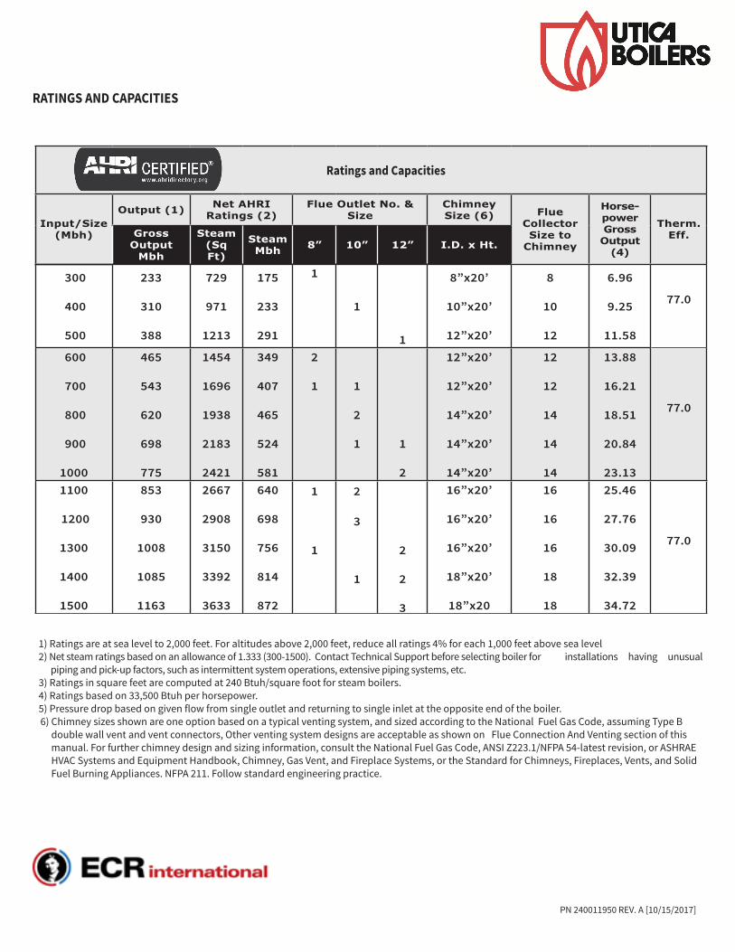
RATINGS AND CAPACITIES
1) Ratings are at sea level to 2,000 feet. For altitudes above 2,000 feet, reduce all ratings 4% for each 1,000 feet above sea level2) Net steam ratings based on an allowance of 1.333 (300-1500). Contact Technical Support before selecting boiler for installations having unusual
piping and pick-up factors, such as intermittent system operations, extensive piping systems, etc.3) Ratings in square feet are computed at 240 Btuh/square foot for steam boilers.4) Ratings based on 33,500 Btuh per horsepower.5) Pressure drop based on given flow from single outlet and returning to single inlet at the opposite end of the boiler.6) Chimney sizes shown are one option based on a typical venting system, and sized according to the National Fuel Gas Code, assuming Type B
double wall vent and vent connectors, Other venting system designs are acceptable as shown on Flue Connection And Venting section of this manual. For further chimney design and sizing information, consult the National Fuel Gas Code, ANSI Z223.1/NFPA 54-latest revision, or ASHRAE HVAC Systems and Equipment Handbook, Chimney, Gas Vent, and Fireplace Systems, or the Standard for Chimneys, Fireplaces, Vents, and Solid Fuel Burning Appliances. NFPA 211. Follow standard engineering practice.
PN 240011950 REV. A [10/15/2017]

C D E
Flue Outlets
ReturnReturn
Supply Supply
Supply Supply
Water Line
Floor Line
Boiler Model
No.
Water Content in
Gallons
Shipping Weight
Lbs.
A Jacket Width L to R
AA Base & Battery Length
C D E F*Boiler Modules
*1 *2 *3
300400500
202530
92211331344
20 3/425
29 1/4
16 3/421
25 1/4
10 3/812 1/214 5/8
–––
–––
10 3/812 1/214 5/8
300 400 500
x x x
x x x
600700800900
1000
3540455055
15551766197721882399
33 1/2 37 3/4
4246 1/2
50
29 1/234 3/4
3842 1/446 1/2
10 3/810 3/812 1/212 1/214 5/8
12 3/414 7/8
1719 1/821 1/4
–––––
10 3/812 1/212 1/214 5/814 5/8
300 300 400 400 500
300 400 400 500 500
xx x x x
11001200130014001500
6065707580
26102821303232433454
54 3/459
63 1/467 1/271 3/4
50 3/455
59 1/463 1/267 3/4
10 3/812 1/210 3/812 1/214 5/8
14 7/81717
19 1/821 1/4
1717
21 1/421 1/421 1/4
12 1/212 1/214 5/814 5/814 5/8
300 400 300 400 500
400 400 500 500 500
400 400 500 500 500
Front View Left Side View
Top View
ALL SUPPLY AND RETURN CONNECTIONS ARE 4 INCH
38”
29½”
AA
A
F
1 2 3
PN 240011950 REV. A [10/15/2017]

PN 240011950 REV. A [10/15/2017]
STEAM BOILER PIPING
SKIM TEE
29½”
Optional Location for Make-up
Water Connections
A
B
A
B
C
D
E
F
G
OPENING SIZE STEAM
A 4” Supply and Return
B ½” Primary LWCO and Gauge Glass Set
C ¾” Drain, Left End
C ¾” Drain, Right End
D ½” Plugged
E 1” Accessories
*F 1” Safety Valve
G ¾” Plugged or Electronic (Probe Type) LWCO
*If using opening F for other than Safety Valve or Safety Relief Valve, or Safety/Relief valve is larger than 1”, Install Safety/Relief Valve in Header Piping as near boiler as possible.
