java uml reverse engineer (ure) peter muchogu · • a graphical user interface (gui) that displays...
TRANSCRIPT

" The candidate confirms that the work submitted is his/her own and the appropriate credit has been given where reference has been made to the work of others" .
Java UML Reverse Engineer (URE)
Peter Muchogu
MSc Distributed Multimedia Systems (DMS) 2000/2001

UML Reverse Engineer (URE)
Peter Muchogu MSc in Distributed Multimedia Systems 2
1. SUMMARY The main objective of the project is to create a multi-platform application whose primary function is to generate UML class diagrams from Java classes. Other more general objectives included exploring the features provided by UML and CASE tools and the improvement of my Java programming abilities especially in the areas covered by the Java Reflection and Graphics APIs, with the aim of increasing my understanding in these areas. To achieve these objectives I built an application, the UML Reverse Engineer (URE) using Java that was able to analyze Java classes in the form of Java byte code and optionally Java source code (text). The URE is able to reverse engineer a UML class diagram from the Java classes by utilizing tools available from the Reflection package to analyze the Java byte code and a rudimentary text-searching algorithm to extract pertinent information from the Java source code. The URE also has a Graphical User Interface (GUI), which displays the reconstructed UML class diagram. Features of the GUI included a mouse function that allows users to reposition individual classes around the screen to aid clarity and a comprehensive menu that avails users with the ability to load and save class diagrams from and to files on disk just to mention a few. The GUI and the ability to analyze Java classes together form the core of the URE. An extra feature not in the minimum requirements of the project is a layout manager that is able to automatically reposition the class diagram elements so that there are the fewest number of line crossings and overlapping elements i.e. finds the optimum layout for the class diagram displayed in the GUI. The core part of the URE can run on any platform that supports the Java 2 platform. (JDK 1.3 and above recommended.) It has been tested on both windowsNT/2000 and Linux Red Hat 7.0. The layout manager currently runs only in the windows environment, but could in the future be extended to include the Linux. This said, the layout manager can still work on any system has an Internet connection as the platform dependent part of the layout manager can be run remotely from a website.

UML Reverse Engineer (URE)
Peter Muchogu MSc in Distributed Multimedia Systems 3
2. ACKNOWLEDGMENT I would like to thank supervisor, Dr Nick Efford for his help and advice throughout the Project.

UML Reverse Engineer (URE)
Peter Muchogu MSc in Distributed Multimedia Systems 4
3. CONTENTS
1. SUMMARY ..................................................................................................2
2. ACKNOWLEDGMENT ................................................................................3
3. CONTENTS .................................................................................................4
4. INTRODUCTION..........................................................................................6
5. BACKGROUND...........................................................................................7 5.1 The Unified Modeling Language (UML)..........................................................7
5.1.1 Definition: .................................................................................................7 5.1.2 Goals of UML ...........................................................................................8 5.1.3 Class Diagrams..........................................................................................9 Notation used in class representations ..............................................................10 Class diagram Relationships.............................................................................11
5.2 Java................................................................................................................14 5.2.1 Why Java was chosen..............................................................................14 5.2.2 The Java Graphics API(s). .......................................................................14
5.2.3 The Java Reflection API - Overview ......................................................15 5.3.4 Reflection Model.....................................................................................15
6. IMPLEMENTATION...................................................................................17 6.1. Reflection – gathering information. ...............................................................18 6.2. Relationships – establishing links..................................................................19
6.3.a. Generalizations and realizations..............................................................19 6.3.b. Associations. ..........................................................................................19
6.3. The Graphical User Interface (GUI) ..............................................................19 6.3 a. Drawing Area.........................................................................................20
Drawing the classes:.....................................................................................20 Drawing relationships: .................................................................................20
6.3 b. Dialog boxes .........................................................................................21 6.3 c. Main Menu. ............................................................................................21 6.3 d. Layout Manager. ....................................................................................22
7. EVALUATION AND TESTING...................................................................25
7.1 Evaluation criteria: ..........................................................................................25
7.2 Testing..............................................................................................................25
7.3 Results ..............................................................................................................27
8. LIMITATIONS ............................................................................................27
9. FURTHER WORK......................................................................................28

UML Reverse Engineer (URE)
Peter Muchogu MSc in Distributed Multimedia Systems 5
10. CONCLUSION.........................................................................................28
11. REFERENCES.........................................................................................30
12. APPENDICES..........................................................................................31
Appendix A – Reflection on the project. ...............................................................31
Appendix B – copy of Objectives and Deliverable form.......................................32
Appendix C - marking scheme, header sheet and assessors comments for the marked Interim Report .........................................................................................34
Appendix D – Screen shots of the URE’s menu....................................................36
Appendix E – screen shots of the URE’s dialog boxes in action...........................39
Appendix F – screenshots of the layout manager in action. .................................40
Appendix G - Miscellaneous screenshots. .............................................................41
Appendix H - Dummy code used to test the URE.................................................43 Dummy code #1...................................................................................................43 Dummy code #2...................................................................................................43
Appendix I – testing...............................................................................................45
Appendix J - Reflection and Relationships..........................................................48
Appendix K – Evolution of UML ..........................................................................49

UML Reverse Engineer (URE)
Peter Muchogu MSc in Distributed Multimedia Systems 6
4. INTRODUCTION UML, which stands for Unified Modelling Language is a language for designing an object orientated model to describe the system. It was the brainchild of Grady Booch, James Rumbaugh and Ivor Jacobson. Its inception was in late 1995 and was essentially an amalgamation of object orientated modeling techniques developed by its original founders. In normal use the UML is used to aid developers in the planning stage through to the actual implementation and maintenance stages. This progression of software engineering is known as forward engineering. Conversely the project aims to reverse engineer Java classes.
4.1 Objectives • Learn about UML and learn how it is used for visual modelling and code
generation. • Improve my Java programming skills especially in using the Java Graphics
and Reflection APIs. • Develop a Java software prototype that analyzes Java byte code and generates
UML class diagrams from it.
4.2 Deliverables a) A project report b) A software prototype
4.3 Minimum requirements • An application that reads Java classes provided to it and extracts information such attributes and local methods. • A Graphical User Interface (GUI) that displays the extracted information as a Class diagram.
4.4 Current State of the art There are many commercial visual modelling tools that have reverse engineering tools built in. Examples of these include Rational Rose and MagicDraw. Rational Rose is a product from Rational, a company founded by the Booch et al. It provides a tool to reverse engineer Java code in one of its menus. MagicDraw is a visual UML modeling and CASE tool with teamwork support. MagicDraw supports the latest standards of Java, UML and XMI and provides full round-trip support for Java programming languages. MagicDraw also provides reverse engineering facilities.

UML Reverse Engineer (URE)
Peter Muchogu MSc in Distributed Multimedia Systems 7
5. BACKGROUND
5.1 The Unified Modeling Language (UML). 5.1.1 Definition: The Object Management Group (OMG) ’s specification defines UML as:
"A graphical language for specifying, visualizing, constructing, and documenting the artifacts of software systems.”
UML is an open standard and as such anyone can download the complete UML specification from OMG 's Web site free of charge (http://www.omg.org). OMG controls the process of maintaining and extending UML. Other companies can and have joined the standards organization and have contributed to the development process of UML now in UML 1.4 (see Appendix K for evolution of UML). UML represents a collection of proven successful best engineering practices that have in the modeling of large and complex systems. The Unified Modelling language (UML) is, as the name suggests, a unification of a number of earlier object-oriented modelling languages. The three principal designers of UML had each previously published their own methods, and the explicit purpose of UML was to integrate the insights of these three methods. This integration was aided by the common framework, in the form of the object model, shared by the original methods. (Mark Priestly, Practical Object-Oriented Design with UML.) UML It is the product of the amalgamation of the modeling languages found in the Booch, OOSE/Jacobson, OMT and other methods. The UML standard covers disciplines such as business modeling, requirements management, analysis & design, programming and testing. Prior to the inception of the UML, there was no universally accepted modeling language. Users had to choose from a plethora of similar modeling languages with slightly different approaches to modeling. It turns out that most of these modeling languages shared a set of commonly accepted concepts the differences were due to the slightly different notations they used. The many approaches used had the effect of fragmenting the object oriented industry, as a result many new users were put off from learning and using visual modelling techniques. Developers wanted the software industry to agree on one broadly supported modeling language that was suited to general-purpose use i.e. they wanted a lingua franca for modelling software. UML defines a language only, and as such provides no description or recommendations relating to the process of development (Mark Priestly, Practical Object-Oriented Design with UML.) Software professionals to create virtual models of software systems they plan to build use the Unified Modeling Language (UML) especially when they want to model large complex software applications. They do this for the same reason people hire architects to design buildings before actually building them e.g. it is easier and less expensive to make corrections and alterations on the models than it is to make changes after implementing the systems thus in the long run, a well designed and documented

UML Reverse Engineer (URE)
Peter Muchogu MSc in Distributed Multimedia Systems 8
system saves both time and money. UML enables developers to plan their software better by making them consider their alternatives, select the best option, work out details, and achieve agreement before they start the building the application. As mentioned earlier it is much less costly to use a model than it is to modify a building or a software application after it has been assembled. A secondary but no less important advantage of using UML in the development process is the documentation generated. This is important as typically 90% of the costs involved in large applications are as a result of changes, extensions, and other maintenance to the software systems after they have been built. The UML documentation with its innate clarity is able to not only direct these changes but also document them in case they have to be revised at a future date. 5.1.2 Goals of UML The primary goals in the design of the UML were as follows:
1. Provide users with a ready-to-use, expressive visual modeling language so they can develop and exchange meaningful models.
2. Provide extensibility and specialization mechanisms to extend the core concepts.
3. Be independent of particular programming languages and development processes.
4. Provide a formal basis for understanding the modeling language. 5. Encourage the growth of the OO tools market. 6. Support higher-level development concepts such as collaborations,
frameworks, patterns and components. 7. Integrate best practices.
Chris Kobryn, document omg/01-03-02 updated UML lecture 1, March 2001 version.
Figure 1: The structure of UML software systems known as the 4+1 view model. By amalgamating all five views in figure 1, it is possible to model the complete system, but for particular purposes it may be sufficient to consider only the information contained in just a few of the views leaving out some of the views. The use case view defines how the system interacts with the external world. It is particular interest to end users, analysts and testers of the system. It defines the requirements of the system and plays a central role as it constrains the other views and is often said to drive the development process.
Design View
Process View
Implementation
View
Deployment View
Use Case View

UML Reverse Engineer (URE)
Peter Muchogu MSc in Distributed Multimedia Systems 9
The design view describes the logical structures that support the functional requirements of the system as expressed in the use case view. It consists of definitions of program components, mainly classes together with any specifications of the data they hold, and their behaviours and interactions. A class diagrams is an example of a design view. The implementation view describes the physical components from which the system is to be constructed. They are different from logical components and include things like executables files, code libraries and databases. This information is particularly useful in configuration management and system integration. The process view deals with issues of concurrency within the system i.e. how processes and events in the system are ordered with respect to each other. The deployment view deals with how the physical components of the system are distributed in the physical environment e.g. distribution over a computer network.
Diagram View
1. Use case diagram Use case view
2. Class diagram Design view
3. Object diagram Use case and design views
4. Sequence diagram Use case and design views
5. Collaboration diagram Use case and design views
6. State-chart diagram Design view
7. Activity diagram Design view
8. Component diagram Implementation view
9. Deployment diagram Deployment view
Table 1: UML diagram types. Information contained in a UML model is usually represented in graphical form using the diagram types in Table 1.
5.1.3 Class Diagrams
Classes categorise the objects that exist in the system and define their shared properties. Class diagrams show the classes and variety of relationships between the classes.
classA
- attribute01 + attribute02 : Boolean { final} # attribute03 : Integer - operation01() { throws exception } # operation02(String, int) + operation03(boolean) : String Figure 2: Basic notation for classes.
operations
attributes
Class name

UML Reverse Engineer (URE)
Peter Muchogu MSc in Distributed Multimedia Systems 10
Construct Descr iption Syntax
class A class describes of a set of objects that share the same attributes, operations, methods, relationships and semantics. In class-based object oriented languages like Java, every object belongs to a class.
interface An interface defines features in particular operations that other modules depend on i.e. a named set of operations They are useful as they mean a module implementing a well-defined interface can change internally without necessitating extensive changes elsewhere in the system.
constraint This is a condition that has to be satisfied for correct implementation of the software e.g. student studies alongside an association between a student object and a course object.
Table 2: Some of the elements in a class diagram.
Notation used in class representations In class-based object oriented languages like Java, every object belongs to at least one class. UML class objects contain the name, attributes and operations of the class (see figure 2 above). Operations can be defined as the ways in which objects may interact i.e. behaviours of objects. Attributes on the other hand describe the data contained in an object of the class.
a. Attributes syntax:
[visibility] [type] name [{properties}] [visibility] Symbol ‘+’ , ‘ -’ and ‘#’ are used to represent the access levels of the
attributes. The symbols represent public, private and protected respectively. However during design, access levels are hardly used due to the fact that access levels are language dependent and are not supported by all programming languages e.g. attribute01 in figure 2 has prefix ‘ -’ , signifying it has a private visibility
[type] This is the type of the attribute e.g. attribute03 in figure 2 is of type Integer.
[{properties}] Consists of a list of the constraints on the attribute e.g. attribute02 has a property of final which in Java means that the attribute has the constraint of not being able to assigned new values after the initial declaration.
Table 3: brief description of attribute syntax.
{constraint}
«interface»

UML Reverse Engineer (URE)
Peter Muchogu MSc in Distributed Multimedia Systems 11
b. Operations syntax:
[visibility] [return-type] name [(parameters)] [{properties}] [visibility] Same as in visibility of attributes above i.e. represent the access
levels of the attributes e.g. operation02 in figure 2 has prefix ‘#’ , signifying it has a protected visibility
[(parameters)] This is made up of all the types of the arguments/messages passed to this operation separated by a comma e.g. operation02 in figure 2 has two arguments passed to it, the first is of type String while the second is of type int.
[: return-type] This is the type of message that is returned by this operation. e.g. operation03 in figure 2 has a String return-type.
[{properties}] Consists of a list of the constraints on the attribute e.g. operation01 throws an exception. This is important, as an object utilizing this operation needs to know that it has to handle this exception.
Table 4: brief description of operations syntax. Class diagram Relationships In UML, classes can be connected/linked by means of associations, generalization or aggregation among others.
Table 5: Some of the Relationships in a class diagram.
Construct Descr iption Syntax association Shows that there is a relationship between
two or more instances of classes. The links between the classes can be considered as instances of association.
aggregation and
composition
A special form of association that specifies a whole-part relationship between the aggregate (whole) and the component part.
generalization a taxonomic relationship between a more general and a more specific element.
dependency a relationship between two modeling elements, in which a change to one modeling element (the independent element) will affect the other modeling element (the dependent element).
realization a relationship between a specification and its implementation.

UML Reverse Engineer (URE)
Peter Muchogu MSc in Distributed Multimedia Systems 12
Associations Associations express the relationship between classes i.e. an association between two classes implies links between instances of the classes. e.g. class A and class B are associated if an instance of class A knows about an instance of class B and or vice versa i.e. if
��A class A object contains an instance of class B ��A class A object has an attribute whose values include one or more instances
of class B objects. ��A class A object receives a message with a class B object as one of its values. ��A class A object sends messages to a class B object.
Figure 3: A simple example of an association between classes. An open arrowhead at the tip of the association line is sometimes used to show the direction (navigability) of the association. An association line without any indication of direction can generally be assumed to be same as a double-headed association line i.e. it implies a two-way association where both classes know about each other.
Aggregation and composition As mentioned in table 5, aggregation and composition are kinds of associations. In addition to showing that two classes are associated, they show that an object of one class is part of another class object. The difference between aggregation and composition is composition is a special kind of aggregation with extra restrictions. In composition, the whole has very strong links with its parts e.g. if the whole part is deleted the all its parts are also deleted. This means that a part cannot be have more than one whole. (Take part to be the object that makes up part of another object and that the whole is the object made up one or more parts.)
figure 4: an aggregation, ten or more Modules make up one or more Courses.
figure 5: a composition, sixty four Squares(parts) make one Chessboard(whole).
Generalisation
work for Employee Company
10..* 1..* Course Module
64 1 Chessboard Square
Animal
Dog
Figure 6: an example of a generalisation.

UML Reverse Engineer (URE)
Peter Muchogu MSc in Distributed Multimedia Systems 13
This is because conceptually every dog is an animal. Generalization can be loosely seen as inheritance, where one class inherits ( in the case of Java extends ) attributes and behaviors of another class. Realization
<<interface Marks>>
+ getMarks(): int
Module
- marks: int
+ getMarks(): int
figure 7: an example of a realization. Module implements interface Marks.

UML Reverse Engineer (URE)
Peter Muchogu MSc in Distributed Multimedia Systems 14
5.2 Java The Java programming language is now in the second version of its specification (Java 2) and the forth incarnation of its Java development kit (JDK 1.3). It was created in 1991 by Sun Microsystems, and was initially designed as a platform independent language that could be used on many different systems from personal computers to consumer electronic devices like videos. They also wanted to remove the need for full CPU-specific compilers for each OS platform. With the increased popularity of the World Wide Web, the initially concept ideals were altered in 1995. Sun still kept the platform independent concept of the language, as they saw that improving interactivity of client side programs would still require programs to have cross platform portability. Currently Java is aimed more at personal computer architectures; the consumer electronic devices part of the initial concept has been scaled down The Java compiler produces byte code files, which have a .class extension instead of the more conventional binary executable files that might be produced by a C++ compiler for example . These .class files can be viewed as versions of the source code optimized for execution by the Java Virtual Machine(JVM). At execution the Java byte code is interpreted by a JVM that has been designed to run on a specific platform, so the same byte code can run on any operating system with a JVM. This means that whilst the compiled Java programs are platform independent, the JVM is platform specific. But taking all this into account, the overall cost involved in creating the JVM for each type of system substantially less than the cost of implementing different programs for each platform for all the software produced. The main limiting factor is the fact that Java interprets its code instead of producing binary executables that directly interface with the operating system. This is because there are significant performance issues associated with this type of interpretation especially in computationally expensive applications and in graphically environments. The new release of Java 2 and the JDK 1.3, has improved performance especially the graphics part but the issue of runtime performance still remains. 5.2.1 Why Java was chosen. As Java is an Object Oriented language i.e. it like UML follows the object oriented paradigm, this means that it has many useful features that aid developers to produce better software; features include its inherent security and robustness, better scalability, readability and maintainability. The take up of Java was smoothed by its close syntax similarity to C++, which was already at the time of developing Java established as an industry standard especially in the object oriented arena. However there are some major differences between the languages such as automatic garbage collection and inbuilt multithreading provided by Java but absent from C++. The most important difference especially pertaining to this project is the fact that Java provides reflection and C++ does not. 5.2.2 The Java Graphics API(s). Java2 introduced the j ava. swi ng API, which is made up of graphical interfaces that are mainly improvements on previous Java 1 interfaces. Many of the classes are extensions of the Abstract Windows Toolkit API (java.awt), while some are

UML Reverse Engineer (URE)
Peter Muchogu MSc in Distributed Multimedia Systems 15
completely new as the foundations of j ava. swi ng are j ava. awt and the new Java2D toolkit. With the advent of Java 2 there has been the incorporation of the Swing components into the main Java API. The Java 2 API still includes the AWT classes because many of the Swing classes depend on them e.g. j ava. event . awt . MouseLi st ener .
5.2.3 The Java Reflection API - Overview “Reflection enables Java code to discover information about the fields, methods and constructors of loaded classes, and to use reflected fields, methods, and constructors to operate on their underlying counterparts on objects, within security restrictions. The API accommodates applications that need access to either the public members of a target object (based on its runtime class) or the members declared by a given class.”
JavaTM 2 SDK, Standard Edition Documentation. The Java(TM) Core Reflection API provides a small, type-safe, and secure API that supports introspection about the classes and objects in the current JVM. If permitted by security policy, the API can be used to:
a) Construct new class instances and new arrays b) Access and modify fields of objects and classes c) Invoke methods on objects and classes d) Access and modify elements of arrays
JavaTM 2 SDK, Standard Edition Documentation describes three objects of type class Fi el d, class Met hod, and class Const r uct or at the core of the Reflection API. These objects can be utilized to provide the reflective information about the underlying attributes, members and constructors respectively. Reflection makes use of methods in class Cl ass to construct new instances of the Fi el d, Met hod, and Const r uct or classes. The utility class Modi f i er can then be used in the decoding of the Java language modifier information in the reflective information e.g. the return type of a method.
5.3.4 Reflection Model The three classes Fi el d, Met hod, and Const r uct or are final. Only the Java Virtual Machine may create instances of these classes; these objects are used to manipulate the underlying objects; that is, to:
• get reflective information about the underlying member or constructor • get and set field values • invoke methods on objects or classes • create new instances of classes
Only the first two of these features is applicable to this project. The other features are also useful especially when using Java Beans where situations might arise that require a class to be created during runtime.
Field Objects The Fi el d objects represent reflected fields. The fields may be static class variables or none static instance variables. Methods of class Fi el d can be used to obtain the name and type of the underlying field.

UML Reverse Engineer (URE)
Peter Muchogu MSc in Distributed Multimedia Systems 16
Method Objects Methods in a class may be abstract, instances, or static classes. Class Met hod provides methods that can be used to obtain the parameter types, the return type as well as checking if the methods throw any exceptions.
Constructor Objects Methods of class Const r uct or are used to obtain the formal parameter types and the checked exception types of the constructors of the class object being inspected.
Modifier Class. The Modifier class is a static class. It provides methods to decode Java language modifiers for classes and members. The language modifiers are encoded as integers as defined by the JVM Specification encoding constants
Member Interface Field, Method and Constructor classes implement the Member interface. Methods provided by class Member are utilized to extract identifying information. The identifying information consists of the name of the class or interface that declared the member, the name of the member itself and the check whether the objects are public, protected, abstract and synchronized.
Const r uct or Const r uct or provides information about, and access to, a single constructor for a class.
Fi el d A Fi el d provides information about, and dynamic access to, a single field of a class or an interface.
Met hod A Met hod provides information about, and access to, a single method on a class or interface.
Modi f i er The Modi f i er class provides static methods and constants to decode class and member access modifiers.
Table 6: Summary of Reflection API’s primary methods as specified in Sun’s Java documentation.
Java documents states that Reflection allows runtime access to information about the fields, methods and constructors of loaded classes. Reflection can also be used to operate on the underlying counterpart objects, within security restrictions. Classes in the reflection package along with j ava. l ang. Cl ass are sometimes used by services such as Object Serialization and Java Beans that sometimes need access to information about objects during execution. Reflection is also used by applications such as debuggers, interpreters, and class browsers.

UML Reverse Engineer (URE)
Peter Muchogu MSc in Distributed Multimedia Systems 17
6. IMPLEMENTATION
Figure 8: Design of the final URE.
Gather information to be used to construct Class Diagram
1. Reflection Extract information about the classes provided using the tools provided by the Java Reflection API.
2. Relationships Use the information gathered in part 1 to establish the relationships between the classes.
3. The Graphical User Interface (GUI). Used to display the class diagram. Also provides functionality to control how it is displayed.
a. Drawing Area Provides the main interface where
the user can view the class diagram.
c. Menu Provides the user with standard menu functions like Open, save and Exit as well none standard functions to enable the user to control what appears in the drawing area. Also uses the layout manager.
d. Layout manager Used to display the class diagram that has been auto-arranged using the dot program.
Source code (.java file(s))
b. Dialog Boxes Used to display the details of individual class objects.
Byte code (.class file(s))
(Optional)

UML Reverse Engineer (URE)
Peter Muchogu MSc in Distributed Multimedia Systems 18
The implementation of the UML Reverse Engineer (URE) can be broken down into three parts.
1. Reflection – This involves the gathering of information from the java .class files.
2. Relationships – This looks at the information gathered and tries to find any inter-relationships.
3. The Graphical User Interface (GUI) – The visual components of the URE.
(See figure 8 on the previous page for the design of the overall system. Figure 11, page 25 shows the class diagram. Appendix J has a figure showing how reflection and especially relationships are actually implemented)
6.1. Reflection – gathering information. This takes in the name of the class being inspected (as given in the command line arguments) and creates and instance of the class, provided the class exists in the java class path. The URE then calls the inspect method in class Cl assI nspect or .
I nspect ( ) is able to examine the class, extract information from it using reflection. The information is then stored in the Vect or v. The process is repeated for all the classes in the command line arguments.
Cl assI nspect or obj _cl s = new Cl assI nspect or ( ) ; Vect or dat a = new Vect or ( ) ; Cl ass cl s = Cl ass. f or Name( name_cl s ) ; dat a = obj _cl s. I nspect ( c l s ) ;
. . . / / accumul at e al l t he dat a f or al l c l asses i nt o one Vect or v. f or ( i nt i = 0; i < dat a. si ze( ) ; i ++) {
Cl assI nf o i nf o = ( Cl assI nf o) dat a. el ement At ( i ) ; v. addEl ement ( i nf o ) ;
}
Cl assI nspect or . i nspect ( ) with the help of other methods in Cl assI nspect or gets the class’s name, fields (attributes), constructors ( operations part 1), methods (operations part 2), interfaces (realization), the package the class belongs to and finally its superclass.
// method: ClassInspector.inspect() publ i c Vect or Inspect( Cl ass c ) {
c l assI nf o = new Cl assI nf o( ) ; c l assI nf o. cl s_name = c. get Name( ) ; // get name f i ndFi el ds( c) ; // get attributes f i ndConst r uct or s( c) ; // get operations part 1 f i ndMet hods( c) ; // get operations part 2 f i ndI nt er f aceNames( c) ; // get realization f i ndPackage( c) ; // get the package this class
// belongs to. Cl ass super _cl s = c. get Super cl ass( ) ; i f ( super _cl s ! = nul l )
r et ur n I nspect ( super _cl s ) ; // Call the method // recursively until // there are no more // superclasses.
}

UML Reverse Engineer (URE)
Peter Muchogu MSc in Distributed Multimedia Systems 19
6.2. Relationships – establishing links
6.3.a. Generalizations and realizations.
The second stage is to use the information gathered in reflection above and uses it to establish the relationships between the classes found. Each Cl assI nf o object stores the name of its super class (generalization) and the names of the interfaces it implements (realizations). It is possible by searching the main Vector v to establish how the classes are interrelated. This proved more difficult to implement than it first appeared, the solution I finally used was to search the Vector v for classes whose names match those in the set of generalisations and set of realisations in stored in the particular Cl assI nf o object whose relationships are being ascertained and store its position in Vect or v in the Class object e.g.
If v. el ement At ( 2) is the super class of v. el ement At ( 5) , then v. el ement At ( 5) adds the number 2 to is set of generalizations.
This enables the URE to know that the object at position 5 in Vect or v is related to the object at position 2 in Vect or v and that their relationship is a generalization (realization relationships are stored in a set of interfaces as opposed to a set of generalizations). This becomes particularly handy when it comes to determining links and the location of the objects they are linking are.
6.3.b. Associations.
The case of associations is slightly different. It is possible to determine if class A is associated with class B by searching through the attributes (fields) and operations (methods) of class B for occurrences of objects or messages that are of type class A. This works in cases where the programmer has decided to make the associated object an attribute or message (return type or pass-by value of a method) of the class. However UML does not restrict associations to instances of one class that have been declared as attributes or form part of the messaging of another object class, it only requires that one or both of the objects know about each other. This means that the object instance could be declared anywhere in the code. To overcome this problem the URE has the ability to read in the actual source code and perform a simple text search for looking for occurrences of the classes involved in the source code. In both cases if it finds an instance of a class e.g. there is an instance of class A in class B, the URE adds the name of class A to the set of associations in the Cl assI nf o object pertaining to class B. The association relationships are then enumerated exploiting the same method as described above for generalizations and realizations relationships, for the same reasons.
6.3. The Graphical User Interface (GUI) The GUI consists of:
a. A drawing area b. Dialog boxes c. A menu, and d. The Layout Manager.

UML Reverse Engineer (URE)
Peter Muchogu MSc in Distributed Multimedia Systems 20
6.3 a. Drawing Area Drawing the classes: Design possibilities:
a. Use internal frames b. Draw the classes and all their details in the same area. c. Draw rectangles representing the classes and have the details of individual
classes shown in a dialog box on demand. Using internal frames was considered because internal frames allow the placing of text directly in them as the information was already in text format this seem a viable option. Internal frames also have the added advantage of built-in event handling which allows them to be dragged around and using the mouse with hardly any addition code. But having built an application using internal frames it became evident that the display was not very user friendly. This was because whilst internal frames are adequate for displaying one or two classes when it came to several classes the display became very overcrowded and too unwieldy to use. Drawing the classes and all their details as shown in figure 2 in page 9 also proved to be a dead end for similar reasons to using internal frames i.e. It would have required an extremely large area to display just a few classes making it difficult for the user to navigate around, not to mention denying the user an overall view of the systems class diagram especially if the classes being displayed have long lists of attributes and operations. Having explored the first two options and found them wanting, Option (c) to Draw rectangles representing the classes and have the details of individual classes shown in dialog boxes on demand was chosen as it provided the best user-friendly interface and got around the problem of long classes gracefully by using a tree and scrollbars in the dialog box. Drawing relationships: When the relationships have been established (see 2. Relationships – establishing links above). The URE creates a new Link object for each relationship. The link object contains references to the two classes it links. Using these references it is able to determine the type of relationship, which determines the type of link it will draw between the classes. The Link objects are also able to keep tabs on the location of the objects they are linking as well as their orientation relative to each other so that it knows how to draw itself i.e. it starting point and its terminating point. Drawing the complete class diagram with classes and relationships: The class diagram was constructed and displayed by class Dr awi ngPanel that extended j avax. swi ng. Jpanel . The drawing area makes use of double buffering which greatly reduces flickering during repainting it does this by first drawing the entire area on a buffered image in memory and when the drawing is complete swapping the current screen image with the buffered image. The reason for using double buffering was to reduce flickering during when the class objects were being dragged across the screen.

UML Reverse Engineer (URE)
Peter Muchogu MSc in Distributed Multimedia Systems 21
The drawing area is used to draw the class diagram, which basically consists of rectangles labelled according to the class they represent and the linking lines between them that show how they are interrelated. The user can reposition individual rectangles by dragging them using the mouse (any button) to new positions. The user can also click on a rectangle; doing this brings up a dialog box with the details of the particular class that the rectangle the clicked represents. (See 3 b. dialog boxes below) The lines between the rectangles are able to sense the orientation of the class rectangles that they link and redraw themselves to reflect this. For example, if initially the link was drawn from the bottom of classA to top of classB when classA was above classB. If classA is repositioned such that it is now below classB then the link is able to detect this change and now draws it self from the bottom of classB to the top of classA e.g. figure 9 below. 6.3 b. Dialog boxes Each Cl assI nf o object that goes to make up the class diagram has the ability to draw a JDi al og box that contains a tree made up of the details of the class whose information is held by that instance of Cl assI nf o. A dialog box is displayed when a user clicks on a rectangle (in the class diagram) representing a class. The click could occur in either the main drawing area or in the layout frame (part of the layout manager, see below). Only one dialog box of an instance of Cl assI nf o can exist at any one time. Each occurrence of Cl assI nf o contains its own dialog box. The tree in the dialog box is filled with selected information in the Cl assI nf o object. The information in the tree can be portioned as follows:
<< class name >> << attributes >> - if any. << operations >> - if any. associations / contains - if any. generalizations / super-class - if any. realizations / interfaces - if any
(See figures in Appendix E that shows a dialog box in action). 6.3 c. Main Menu.
-> File Open
After Before
classB
classA
Figure 9: Dynamic link lines.
classA
classB

UML Reverse Engineer (URE)
Peter Muchogu MSc in Distributed Multimedia Systems 22
Used to open class diagrams that had previously been saved as a disk file. Save
Used to save the current class diagram to disk. Print
Used to print the current class diagram. Allows the user to choose the print format.
Exit Closes the UML Reverse Engineer.
-> Classes
Filled with all the classes that make up the current class diagram. It allows the user to show or hide individual classes using the provided checkboxes.
-> Details
Filled initially with preset values which allow the user to show or hide groups of objects e.g. user can hide all the classes whose name begins with java by un-checking the check box next to menu item “ java” . Additional values/menu items are added for each package found in the class diagram.
-> Levels
Shows the number of levels in the current class diagram. The user can use show or hide groups of objects by setting the maximum visible level using the radio buttons provided in the menu.
-> Layout
Used to open a new layout frame. Allows the user to choose which program to use when generating the layout. The initially program options where ‘dot’ and ‘neato’ programs, but ‘neato’ was later dropped as it was unable to layout the class diagram in a clear fashion. The user is also able to choose the orientation of the class diagram i.e. top to bottom or left to right the actual elements in the diagram are always right side up.
-> Help Opens up a dialog box with instruction on how to use the program.
(Appendix D has screenshots of the URE’s menus)
6.3 d. Layout Manager.
Problem: After drawing the first couple or so test class diagrams, it became evident that a layout manager was needed. This was because despite the ability to move and rearrange the class objects, the class diagrams with every additional class object become increasingly more complex, interconnected, interweaved web of class objects and links. Eventually they become completely unmanageable, as the user would have to spend a very long time to trying to untangle these complex webs. The solution was to have a layout manager that untangles the class diagrams on behalf of the user. However having looked at developing such a manager from scratch for

UML Reverse Engineer (URE)
Peter Muchogu MSc in Distributed Multimedia Systems 23
the URE, it became apparent that this was way beyond the scope of the project and would have taken more time than was available for the project. Solution: With more research and the guidance from my supervisor Dr. Nick Efford, a compromise was found in the shape of “Gr appa the Java Graph Package” from AT&T labs-Research. Grappa was chosen primarily because it is written in Java and could therefore be more easily incorporated into the URE as it was then.
“ Grappa is a Java graph drawing package that simplifies the inclusion of graph display and manipulation capabilities within Java applications and applets. It has a good number of useful features built into it, but is also extensible. Grappa can be thought of as a port of a subset of Graph to Java. The current version of Grappa was built using the Java Development Kit (JDK) version 1.2 and takes advantage of recent improvements in the JDK such as Java 2D and Swing.”
AT&T labs-Research, last visited 26/08/01.
Integrating Grappa to the URE: By modifying the some of the code that comes with grappa I was able to amalgamate grappa with the URE.
Figure 10: Shows how the grappa layout program ‘dot.exe’ is used to layout the class diagram
Utilising the grappa enabled layout manager: Using the main menu’s Layout options the user is able to rearrange the positions of the objects in the class diagram such that there the fewest possible line crossings and overlaps i.e. the best/optimal layout. The rearranged diagram is the placed in a new window frame, the layout frame that has its own menu.
Information used to generate the current class diagram.
- Read in file uml_dot.dot - Parse it - Generate a graph that Grappa understands.
- Take the graph and pass it to ‘dot.exe’ program. - ‘dot.exe’ lays-out the graph. - Display the laid-out graph and display it
in a new Jframe window.
- Translate the information into ‘dot’ format. - Save the translation as text
Uml_dot.dot

UML Reverse Engineer (URE)
Peter Muchogu MSc in Distributed Multimedia Systems 24
The best laying-out is done with the assistance of the dot program ‘dot.exe’ . The program uses heuristics to find the optimum arrangement for the objects making up the class diagram. The new rearranged diagram retains the ability to bring up the details of a class by clicking on a rectangle with the name of the class whose details you wish to view. It loses the ability to manually reposition the objects using the mouse although this should not be a problem as the diagram is already at it optimum layout and probably does not need rearranging. (See Appendix F for screen shots of the layout manager in action) Supplementary features include the ability to zoom into particular areas of interest by dragging a bounding box over the area, right clicking the mouse and selecting zoom to sweep on the pop-up menu that appears or simply zooming in and out of the diagram as a whole also using the pop-up menu. The bounding box can also be use to select a group of objects which can then be deleted from that diagram using delete option in the popup menu. The layout frame has a print menu that provides the user with the ability to print out the class diagram in that frame. It also has a refresh menu that allows the user to redraw the diagram thereby maintaining the diagram at it optimal layout. Currently this is done manually but might in the future be automated so that the diagram is always at its optimal layout by taking into account of any changes made to the diagram. The layout frame was the last part of the program to be added and as such is still under construction as there are still some latent bugs that are yet to be abrogated. This can be best demonstrated by the fact that the dialog boxes don’t always appear when a rectangle on the class diagram is clicked.
Figure 11: Class Diagram of the URE.
UML Reverse Engineer (URE)
Peter Muchogu MSc in Distributed Multimedia Systems 25
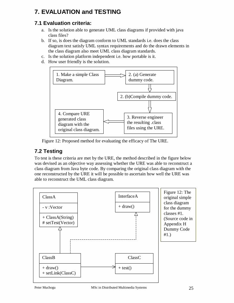
7. EVALUATION and TESTING
7.1 Evaluation criteria: a. Is the solution able to generate UML class diagrams if provided with java
class files? b. If so, is does the diagram conform to UML standards i.e. does the class
diagram text satisfy UML syntax requirements and do the drawn elements in the class diagram also meet UML class diagram standards.
c. Is the solution platform independent i.e. how portable is it. d. How user friendly is the solution.
Figure 12: Proposed method for evaluating the efficacy of The URE.
7.2 Testing To test is these criteria are met by the URE, the method described in the figure below was devised as an objective way assessing whether the URE was able to reconstruct a class diagram from Java byte code. By comparing the original class diagram with the one reconstructed by the URE it will be possible to ascertain how well the URE was able to reconstruct the UML class diagram.
1. Make a simple Class Diagram.
3. Reverse engineer the resulting .class files using the URE.
4. Compare URE generated class diagram with the original class diagram.
2. (b)Compile dummy code.
2. (a) Generate dummy code.
ClassA
- v :Vector
+ ClassA(String) # setTest(Vector)
ClassB
+ draw() + setLink(ClassC)
ClassC
+ test()
InterfaceA
+ draw()
Figure 12: The original simple class diagram for the dummy classes #1. (Source code in Appendix H Dummy Code #1.)

UML Reverse Engineer (URE)
Peter Muchogu MSc in Distributed Multimedia Systems 26
Figure 13: The class diagram as reconstructed by the URE including the dialog
boxes, compare with figure 12 above. (See Appendix I - testing for better close-up screenshots.)
Figure 14: The original simple class diagram for the dummy classes #2. (Source code in Appendix H Dummy code #2)
* 1
Link
+ getName: String + getChild(int): Node + adopt(Node): void
Directory
+ getChild(int): Node + adopt(Node): void
File
Node

UML Reverse Engineer (URE)
Peter Muchogu MSc in Distributed Multimedia Systems 27
Figure 15: The class diagram as reconstructed by the URE including the dialog boxes, compare with figure 14 above (see Appendix I for better close-up screenshots.)
7.3 Results By looking at the class diagrams and dialog boxes produced by the URE, it is possible to confirm that the class diagram and UML text generated do conform to UML standards. The URE is not fully platform independent this is because whilst the URE is entirely written in Java making it platform independent, the URE’s layout manager uses programs the are platform dependent i.e. ‘dot.exe’ . However these programs can run from a website thereby maintaining the URE’s platform independence for systems with Internet connections. The system is very user-friendly. This is because The URE has a simple to use (difficult to build) menu that is clearly labelled and is intuitive to use. It has a main display that allows the user to interact with the class diagram.
8. LIMITATIONS The main limitation of the URE is that it is limited to the Java language as it relies on Java’s reflection abilities to perform its tasks. This means it would be difficult to extend it to other object based languages like C++. Using just reflection techniques it is not possible to reconstruct the original class diagram completely as some of the information are simply not available from the compiled java classes. While some of the information can be extracted from the source code e.g. when looking for associations within methods, a good deal of the information is not available is also not recoverable from the source code. As a result

UML Reverse Engineer (URE)
Peter Muchogu MSc in Distributed Multimedia Systems 28
the reconstructed class diagram may not always completely match the original class diagram. A good number of these discrepancies are due to the non-availability of the information in the implemented solutions. This is because some of the information e.g. composition is conceptual information and does not have a set unambiguous approach of implementation. The URE can be very demanding on a system’s memory and CPU speed. Especially when analysing class diagrams with a very large number of elements in it thus it is not suited to systems with slow processors and low memory.
9. FURTHER WORK There are just two known small bugs that are yet to ironed out. The first being, arrays are not displayed properly especially when they are multidimensional arrays. This is because when using reflection arrays have special prefixes and suffixes at either end of their names. These prefixes and suffixes have proved difficult to automatically interpret for multidimensional arrays. The second is in the layout frame of the layout manager. The layout frame does not always respond correctly to clicks especially when trying to open dialog boxes. The layout manager is platform-dependent as the graph layout program it uses only works in the windows environment. A challenge for the future would be to build wholly in Java a graph layout program thus maintaining the platform independence of the URE. The URE’s user-friendliness could be improved by allowing the user to select Java .class (files to be reverse engineered) using a graphical file browser, this would make it easier for the user to select multiple files. This will make it easier to analyze large numbers of files as the user would not have to type the in at the command line.
10. CONCLUSION The primary objective of the project was to develop an application that is able to reverse engineer a UML class diagram from any Java Classes. The UML Reverse Engineer (URE) was built to achieve this objective. The URE was successful in satisfying the primary objective by taking in any compiled Java classes in byte code file format and reverse engineering a UML class diagram from it. It did this by using the tools provides by the Java reflection API to extract pertinent information from the Java classes, translating and interpreting the information so that a UML class diagram could be constructed from the information gathered. The URE then made use of the Java Graphics API to build the URE’s Graphical User Interface (GUI), which was then used to display the class diagram in a highly interactive and user-friendly fashion. The URE’s GUI is packed with many user-friendly features like a comprehensive menu that not only allows the users to change how the class diagram is displayed but it also updates itself so that the user has feed back on the current state of the URE. The URE’s class diagram is also interactive and allows the user to reposition individual elements in the diagram. The URE goes beyond it scope by providing a layout manager that is able to automatically arrange the elements in the class diagram to achieve the best possible view. The URE also provides printing, saving and loading facilities for the class diagram among other fetures.

UML Reverse Engineer (URE)
Peter Muchogu MSc in Distributed Multimedia Systems 29
As mentioned in the limitations, the URE is limited to only one language Java, this is because Java provides reflection tools without which this project would not be possible as alternatives like developing a Java language parser to parse the Java source code to extract the information required would have been more difficult and thus would have taken more time than was available to implement. Overall the URE was able to reconstruct a reasonable class diagram given the information available to it. This is because UML diagrams are usually used to first design the software before building it (forward engineered). This means that they contain conceptual information for aid clarity in the documentation generated that are not necessarily present after the software has been built. It is therefore possible to come to the conclusion that because UML diagrams are forward engineered they are not necessarily fully reversible. However the URE proves that UML class diagrams are at least partially reversible.

UML Reverse Engineer (URE)
Peter Muchogu MSc in Distributed Multimedia Systems 30
11. REFERENCES Priestly, M (2000), Practical Object-Oriented Design with UML, McGraw Hill Publishing Company. Stevens, P with Pooley R (1999), Using UML – Software Engineering with Objects and Components Updated Edition, Addison-Wesley. Rumbaugh James, Jacobson Ivar and Booch Grady (1999), The Unified Modeling Language Reference Manual, Addison-Wesley. Eriksson Hans-erik, Penker Magus (1998), UML Toolkit, John Wiley & Sons Inc. Fowler Martin, Scott Kendal (2000), UML distilled 2nd Edition: A Brief Guide to the Standard Modeling Language, Addison-Wesley. Smith, M (2000), Java an Object-Oriented Language, McGraw Hill Publishing Company. Deitel, H M, Deitel, P J (1999), Java How to Program, Prentice Hall. Flanagan David (1999), Java in a nutshell: A Desktop Quick Reference, O’REILLY. Dennis Daniels, JUG - Java UML Generator http://jug.sourceforge.net/, last visited 3/9/2000. Matthias Hauswirth, Java Class Browser, http://www.hta-bi.bfh.ch/~hrm/Projects/ToolsAndApps/ClassBrowser/e.html, last visited 3/9/2000. AT&T Labs Research, Grappa http://www.research.att.com/sw/tools/graphviz/packages/grappa.html, last visited 26/08/01. Sun Microsystems Inc, JavaTM 2 SDK, Standard Edition Documentation http://java.sun.com/j2se/1.3/docs/index.html, last visited 3/9/2000. Object Management Group (OMG), UML, http://www.uml.org/, last visited 3/9/2000. Rational Rose, http://www.rational.com/products/rose/index.jsp, last visited 3/9/2000. MagicDraw, http://www.magicdraw.com/, last visited 3/9/2000.

UML Reverse Engineer (URE)
Peter Muchogu MSc in Distributed Multimedia Systems 31
12. APPENDICES
Appendix A – Reflection on the project. The project involved considerable programming in Java. I found this aspect of the project challenging, educational and thoroughly enjoyable. Prior to the project I had very little programming experience using Java that I had comparatively recently started using at the start of the MSc course. One of my reasons of choosing this project was to extend my knowledge of Java in a software development environment. I feel that the project helped increase my understanding of Java in not only the Java Reflection and Graphics API(s) but also the Java language as a whole. The project was my first contact with UML this meant that I had to scale a steep learning curve to gain sufficient insight into UML so that I could complete the project. The approach used in developing the solution was to build numerous mini-applications / prototypes to explore how certain parts of the system could be built. Spiral development process that best fits the development process the project used. The prototypes were continuously tested and refined to produce the final solution. The solution itself (the URE) was able to perform the primary tasks that were set out at the beginning of project. By integrating the layout manager, I was able to go beyond the primary objectives of the project. During the project I encountered many challenges like how to determine relationships and then make sure the objects that are related are able to know to whom they are related and the type of relationship. Problems like this helped test and improve my problem solving aptitude especially in the programming aspects of the project. To make the layout manager work on Linux machines required the installation of third party proprietary software and editing some shell scripts. Unfortunately I was unfamiliar with this type of installation and I was therefore unable to make the layout manager work on Linux machines. Overall I feel that the project was a success as I was able to meet both the projects and my personal objectives.

UML Reverse Engineer (URE)
Peter Muchogu MSc in Distributed Multimedia Systems 32
Appendix B – copy of Objectives and Deliverable form.

UML Reverse Engineer (URE)
Peter Muchogu MSc in Distributed Multimedia Systems 33

UML Reverse Engineer (URE)
Peter Muchogu MSc in Distributed Multimedia Systems 34
Appendix C - marking scheme, header sheet and assessors comments for the marked Interim Report

UML Reverse Engineer (URE)
Peter Muchogu MSc in Distributed Multimedia Systems 35

UML Reverse Engineer (URE)
Peter Muchogu MSc in Distributed Multimedia Systems 36
Appendix D – Screen shots of the URE’s menu
Figure d1: showing the App menu.
Figure d2: showing the classes’ menu filled with all the classes in the current class diagram.

UML Reverse Engineer (URE)
Peter Muchogu MSc in Distributed Multimedia Systems 37
Figure d3: screen shot showing the Details menu filled with the packages that the classes in the current class diagram fall under.
Figure d4: screen shot showing the Levels menu. The levels range from zero to the maximum level found, usually the level of j ava. l ang. Obj ect . The radio buttons are used to hide or show levels. They also indicate the maximum visible level.

UML Reverse Engineer (URE)
Peter Muchogu MSc in Distributed Multimedia Systems 38
Figure d5: screenshot of the layout frame. It enables the user to auto arrange the class diagram using the Grappa API in conjunction with the dot program.
Figure d6: screenshot of the help menu. When Readme is clicked, a dialog box containing text is displayed. The text has instruction on how to use the URE.

UML Reverse Engineer (URE)
Peter Muchogu MSc in Distributed Multimedia Systems 39
Appendix E – screen shots of the URE’s dialog boxes in action.
Figure e1: A screenshot of the URE showing the class diagram and two dialog boxes filled with information about two of the classes in the class diagram.
Figure e2: screenshot showing a close-up of a dialog box displaying the attributes and methods of a class ChessPiece.

UML Reverse Engineer (URE)
Peter Muchogu MSc in Distributed Multimedia Systems 40
Appendix F – screenshots of the layout manager in action.
Figure f1: screenshot showing the URE class diagram in the main drawing area.
Figure f2: screenshot showing the result of using Grappa-dot layout manager. (The class diagram is the grappa version of the class diagram in figure d1 above.

UML Reverse Engineer (URE)
Peter Muchogu MSc in Distributed Multimedia Systems 41
Appendix G - Miscellaneous screenshots.
Figure g1: Using the Detail menu to hide java classes.
Figure g2: Star ting the layout manager using the main menu.

UML Reverse Engineer (URE)
Peter Muchogu MSc in Distributed Multimedia Systems 42
Figure g3: The layout manager ’s layout frame.
Figure g4 Figure g5
Figure g6 Figures g4, g5 and g6 shows deletion of class diagram elements in the layout frame.

UML Reverse Engineer (URE)
Peter Muchogu MSc in Distributed Multimedia Systems 43
Appendix H - Dummy code used to test the URE
Dummy code #1 // file name : ClassA.java
i mpor t j ava. ut i l . Vect or ; i mpor t j avax. swi ng. * ; publ i c cl ass Cl assA ext ends JFr ame { pr i vat e Vect or v = new Vect or ( ) ; publ i c Cl assA ( St r i ng n) { super ( n) ; } pr ot ect ed voi d set Test ( Vect or v01) { v = v01; } }
// file name : ClassB.java
publ i c cl ass Cl assB ext ends Cl assA i mpl ement s I nt er f aceA { Cl assB( ) { super ( " new" ) ; } publ i c voi d dr aw ( ) { } publ i c voi d set Li nk ( Cl assC cl assC) { Cl assC l i nk = cl assC; } }
// file name : ClassC.java
publ i c cl ass Cl assC { Cl assC( ) { } publ i c voi d t est ( ) { Syst em. out . pr i nt l n( " i n cl ass C" ) ; } }
Dummy code #2 // file name : Node.java
publ i c abst r act cl ass Node { pr i vat e St r i ng name; pr ot ect ed Node ( St r i ng n) { name = n; } publ i c St r i ng get Name( ) { r et ur n name; } publ i c Node get Chi l d( i nt i ) { r et ur n nul l ; } publ i c voi d adopt ( Node n) { } }
// file name : Directory.java

UML Reverse Engineer (URE)
Peter Muchogu MSc in Distributed Multimedia Systems 44
i mpor t j ava. ut i l . Vect or ; publ i c cl ass Di r ect or y ext ends Node { pr i vat e Vect or nodes; publ i c Di r ect or y ( St r i ng n) { super ( n) ; } publ i c Node get Chi l d( i nt i ) { r et ur n i < nodes. si ze( ) ? ( Node) nodes. el ement At ( i ) : nul l ; } publ i c voi d adopt ( Node n) { nodes. addEl ement ( n) ; } }
// file name : File.java publ i c cl ass Fi l e ext ends Node { publ i c Fi l e( St r i ng name) { super ( name) ; } }
// file name : Link.java publ i c cl ass Li nk ext ends Node { Node subj ect ; publ i c Li nk ( Node n) { super ( n. get Name( ) ) ; subj ect = n; } publ i c St r i ng get Name( ) { r et ur n subj ect . get Name( ) ; } publ i c Node get Chi l d( i nt i ) { r et ur n subj ect . get Chi l d( i ) ; } publ i c voi d adopt ( Node n) { subj ect . adopt ( n) ; } }

UML Reverse Engineer (URE)
Peter Muchogu MSc in Distributed Multimedia Systems 45
Appendix I – testing
Figure i1: Class diagram for dummy code # 1.
Figure i2: ClassA dialog box.
Figure i3: ClassB dialog box.

UML Reverse Engineer (URE)
Peter Muchogu MSc in Distributed Multimedia Systems 46
Figure i4: ClassC dialog box.
Figure i5: InterfaceA dialog box.
Figure i6: Class diagram for dummy code # 2 drawn in the layout frame.
Figure i7: class File dialog box.

UML Reverse Engineer (URE)
Peter Muchogu MSc in Distributed Multimedia Systems 47
Figure i8: class Node dialog box.
Figure i9: class Directory dialog box.
Figure i10: class Link dialog box.

UML Reverse Engineer (URE)
Peter Muchogu MSc in Distributed Multimedia Systems 48
Appendix J - Reflection and Relationships
Create the links between objects. Output: Vector setOfLinks used to draw the lines between objects. Method: setLinks
Get Class Information using reflection. Output: Vector data containing all the Class and all its super classes up to Object. Information on each class is first stored in UML notation in ClassInfo objects, which are the stored in data. Method: getClassInfo()
Do for all the classes in the input arguments
Get interfaces of each of the ClassInfo Objects also using getGlassInfo(). Output: Get and add interface objects to Vector v. Method: getInterfaces()
Remove duplicate ClassInfo objects Output: Filtered Vector v. Method: filterclassInfo
Get associations between the objects. Searches attributes and methods and finally the source code if it is available of classes for associations. Output: Vector setOfAssociations Method: getAssociations
Remove and duplicate associations Output: Filtered Vector setOfAssociations. Method: filterAssocs()
Find generalisations and realizations. Enumerate all the relationships including associations. Output: Vectors setOfRelate, setOfInterfaces and SetOfAssociations. All these are then added to ClassInfo Objects in Vector V. Method: setRelationships
UML Reverse Engineer (URE)
Peter Muchogu MSc in Distributed Multimedia Systems 49
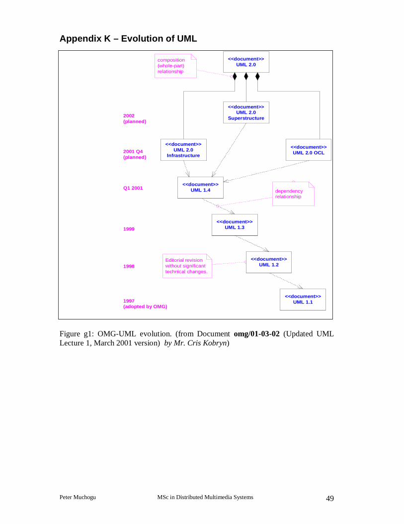
Appendix K – Evolution of UML
Figure g1: OMG-UML evolution. (from Document omg/01-03-02 (Updated UML Lecture 1, March 2001 version) by Mr. Cris Kobryn)
1997(adopted by OMG)
1998
1999
Q1 2001
2001 Q4(planned)
Editorial revisionwithout significanttechnical changes.
2002(planned)
<<document>>UML 1.1
<<document>>UML 1.2
<<document>>UML 1.3
<<document>>UML 1.4
<<document>>UML 2.0
Infrastructure
<<document>>UML 2.0
<<document>>UML 2.0
Superstructure
<<document>>UML 2.0 OCL
composition(whole-part)relationship
dependencyrelationship