jakub machÁlek , barbora frodlovÁ **, radek … making the stamping model in this contribution the...
TRANSCRIPT
241
Transactions of the VŠB – Technical University of Ostrava, Mechanical Series No. 1, 2010, vol. LVI
article No. 1762
Jakub MACHÁLEK *, Barbora FRODLOVÁ **, Radek ČADA ∗∗∗
TUNING OF CRITICAL DIMENSIONS OF TOOL FOR PRODUCTION OF ASYMMETRIC SHAPE STAMPING WITH THE USE OF FEM IN ORDER TO KEEP TO THE TOLERATIONS
SPECIFIED AT PART PRODUCTION DRAWING
LADĚNÍ KRITICKÝCH ROZMĚRŮ NÁSTROJE PRO VÝROBU NESYMETRICKÉHO VÝTAŽKU S VYUŽITÍM MKP ZA ÚČELEM DODRŽENÍ TOLERANCÍ PŘEDEPSANÝCH
NA VÝROBNÍM VÝKRESU SOUČÁSTI
Abstract The contribution concerns the tuning of critical dimensions of tool for production of the car
bodyshell reinforcement asymmetric shape stamping in order to keep to the dimensions and tolerations specified at part production drawing. Final stamping dimensions are generally found out by simulations of drawing process with the use of CAE software in these days. Softwares using the FEM are especially advantageous at intricate asymmetric shape stampings, where the drawing process simulations reach to satisfactory results in comparison with real process. The simulation of drawing process and the evaluation of its results with the use of AutoForm 4.06 software, evaluation of final dimensions of stamping got by simulation and values comparison with dimensions of real stamping got by drawing is described in the contribution. The way of the tuning of the critical dimensions of tool for production of the intricate shape stamping so that all tolerances specified at part production drawing were kept is described in the end of the contribution.
Abstrakt Článek pojednává o postupu při ladění kritických rozměrů nástroje pro výrobu nesymetrického
výtažku výztuhy karoserie automobilu za účelem dodržení rozměrů a tolerancí výtažku předepsaných na výrobním výkresu součásti. Konečné rozměry výtažku se v dnešní době zpravidla zjišťují simulacemi procesu tváření pomocí CAE softwaru. Softwary využívající MKP jsou především výhodné u tvarově složitých nesymetrických výtažků, kde simulace procesu tažení dosahují uspokojivých výsledků srovnatelných s reálným procesem. V článku je popsána simulace procesu tváření a vyhodnocení jejích výsledků pomocí softwaru AutoForm 4.06, vyhodnocení konečných rozměrů výtažku získaného simulací a porovnání hodnot s rozměry skutečného výtažku získaného tažením. V závěru článku je popsán způsob ladění rozměrů nástroje pro výrobu výtažku složitého tvaru tak, aby byly splněny všechny tolerance předepsané na výrobním výkresu součásti.
1 INTRODUCTION Mechanical engineering is one of the most important branches of industry, it subjects to actual
trends and innovative solutions more than any other branch. The endeavour to weather out in hard competition, to be the best and to have own know-how goes the industry forward by big steps. The
* Ing., VŠB – Technical University of Ostrava, Faculty of Mechanical Engineering, Department of Mechanical Technology, 17. listopadu 15, 708 33 Ostrava-Poruba, Czech Republic, tel.: +420 59 7323289, fax: +420 59 6916490, e-mail: [email protected] ** Ing., VŠB – Technical University of Ostrava, Faculty of Mechanical Engineering, Department of Mechanical Technology, 17. listopadu 15, 708 33 Ostrava-Poruba, Czech Republic, tel.: +420 59 7323289, fax: +420 59 6916490, e-mail: [email protected] *** prof. Ing. CSc., VŠB – Technical University of Ostrava, Faculty of Mechanical Engineering, Department of Mechanical Technology, 17. listopadu 15, 708 33 Ostrava-Poruba, Czech Republic, tel.: +420 59 7323289, fax: +420 59 6916490, e-mail: [email protected]
242
new novel resolutions are thought up, the new technologies are used and the research of new materials is carried out. Continuous progress impends thanks to this invention. Automobile industry is a branch of the mechanical engineering, which is mostly developing because of continuous competitive fight to keep in step in areas like material engineering, materials welding, construction of parts and last but not least metal forming too – production of automobile parts, which conform to mechanical properties, safety requirements and they are actual according to their design.
This situation urges the producers to cut the time of preparing tools, mainly in development offices that is why the most modern technologies and innovations are used there. Softwares simulat-ing the forming process with the use of finite elements methods (FEM) are used standardly in these days. These CAE (Computer-aided engineering) softwares imitates a things, states or processes. Simulation is used in many connections like technological simulations for output optimization, safety engineering, testing, training and education. Principe of the FEM consists in distributing (discretiza-tion) of the connected element (stamping) into specific (finite) number of elements (see Fig. 3), whereas the ascertained parameters and calculations are determined in single nodal points. It is valid that with increasing number of elements into which the stamping is distributed the number of nodes increases too and thereby accuracy and objectivity of result are increasing too. Requirements on ca-pability and computer technology output increase too, of course.
For making the stamping model in this contribution the software CATIA V5R16, which is de-veloped by Dassault Systems Company, was used. Many programmes exist on base of finite elements method (FEM). For calculations and simulation of stamping drawing the software AutoForm 4.06 was used.
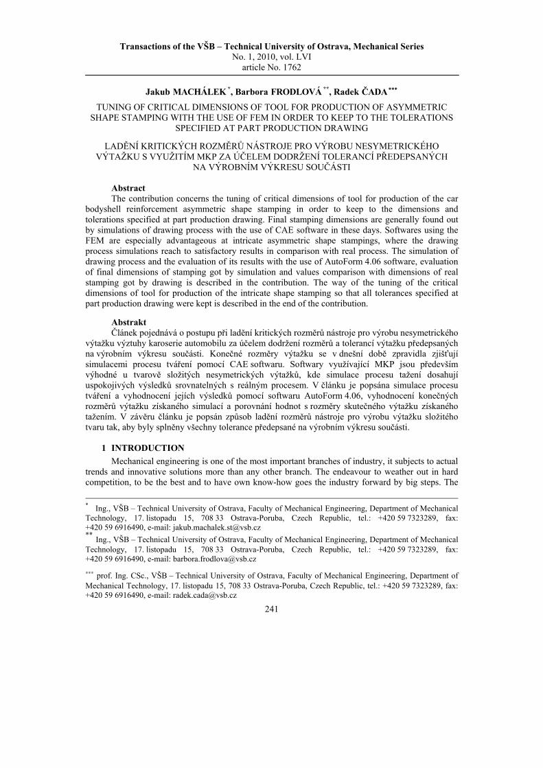
2 CAR BODYSHELL REINFORCEMENT As an intricate shape stamping a functional part of car bodyshell (reinforcement) of a new car,
which is situated in wheel arch (see Fig. 1), was chosen.
Fig. 1 Reinforcement as a functional part of car bodyshell and its location in wheel arch
The wheel arches serves for reaching of optimal properties of car chassis and for coordination of driver comfort with variety of road surface. Every nearer specification, which announces the location, the way of installation and more detailed description and effect of reinforcement are secret generally because of competition and mutual rivalry of car companies. That is why it goes from electronic resemblance of chosen shape stamping (see Fig. 2), from required material properties and
243
productive documentation, e. g. production drawing of the stamping. The production drawing serves like one of tools, when the critical dimensions of drawing tool are tuned.
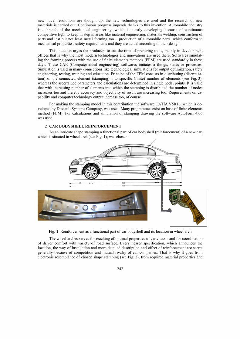
Chosen stamping in digital form CAT Part (computer aided translation) presents interactive visualization of complete final stamping with required dimensional properties (see Fig. 2). Other re-quirements – mostly material and mechanical properties of the given stamping which the stamping has to satisfy are delivered with this digital form.
Fig. 2 Car bodyshell reinforcement model in CAT Part form
For production of car bodyshell reinforcement a required material is the steel H220P, marked ZStE220P too. It is micro-alloy steel, which is cold rolled with higher yield stress determined for cold drawing. Steel can be delivered in annealed and heat treated condition. Sheet-metal surface is high-quality and smooth with finish quality Ra = (0,6 ÷ 1,9) µm. Sheet-metal surface is oiled if it is not agreed differently. The steel has good formability in comparison with common steels for drawing. The steel is well weldable too with the use of common welding methods. Chemical composition and mechanical properties are given by norm EN 10268 (see Tab. 1 and Tab. 2). Colour marking and waste class of deep-drawing micro-alloy steel H220P according to DIN 1.0358 is in Tab. 3.
Tab. 1 Chemical composition of deep-drawing micro-alloy steel H220P according to EN 10268
C (wt. %)
Mn (wt. %)
Si (wt. %)
P (wt. %)
S (wt. %)
Al (wt. %)
Ti (wt. %)
max. 0,06 max. 0,70 max. 0,05 max. 0,08 max. 0,025 min. 0,02 max. -
Tab. 2 Mechanical properties of deep-drawing micro-alloy steel H220P in sheet-metal form with thickness of (0,40 ÷ 2,00) mm according to EN 10268
Thickness (mm)
Yield strength Rp 0,2 (MPa)
Tensile strength Rm (MPa)
Ductility A80 (%)
0,40 ÷ 2,00 220 ÷ 270 320 ÷ 400 32
Tab. 3 Colour marking and waste class of deep-drawing micro-alloy steel H220P according to DIN 1.0358
Colour marking Waste class black – bright-blue 002
244
According to norm EN 10268/98 the steel is delivered in rolls with width by customer´s need, whereas the width is graded by 5 mm, in range of thickness (500 ÷ 1000) mm. The strip length is given by one roll weight. The rolls are delivered in weights 3500 ÷ 5000 kg for the material thickness 0,8 mm and for the width 600 mm.
For production of chosen intricate shape stamping – car bodyshell reinforcement the steel strip with dimensions (0,8 × 555) mm from steel H220P is used. Drawing of this stamping is carried out at a couple of hydraulic drawing and shear presses SHC 400 from firm SCHULER. Anually about 29 000 pieces are produced, correct number depends on number of ordered automobiles.
3 DRAWING PROCESS SIMULATION AND FINDING THE CRITICAL DIMENSIONS
Drawing process simulation of chosen intricate shape stamping – car bodyshell reinforcement was made in software AutoForm 4.06. This software belongs to computational programmes, which are based and worked on base of finite elements method (FEM). It is numerical method for analysis of structures and bodies. The method has many physical applications and the problems in statics, dy-namism and power industry etc. are solved by it. Many specialized programmes exist for various concrete technical problems, like crash-test simulations and simulations of technological processes.
3.1 Definition of all drawing parameters Right definition of drawing parameters and setting of actuating units (brakes, lubrication,
strain rate etc.) is crucial for correction of critical places and tolerances of stamping. The aim is to reach the maximal deformation of the whole material.
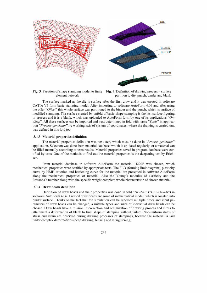
3.1.1 Partition of stamping to finite element network The way of drawing and its parameters must be defined before simulation of drawing process.
Firstly all created surfaces in software CATIA V5 were imported to software AutoForm 4.06. These surfaces were partitioned to finite element network here after unloading. Function ”Title“, which is the first used command in definition of drawing process ”Process generator“, serves to this. Function of this command is in partition of described body (of intricate shape generally) to small parts (ele-ments), which are mathematically described easily. The more possibilities of partition of body to elements exist. The elements can be triangular, rectangular or octagonal shape. One element can give more or less exact result depending on its shape, end conditions and kind of analysis. It is generally true, that with more nodes of elements on model the analysis results are more exacting.
Size and shape of individual elements are predefined in basic setup (see Fig. 3) and they can be changed as need, if the simulation results must be more exact.
3.1.2 Technological properties definition The position of tools in drawing process must be assigned to individual surfaces after discreti-
zation of stamping surfaces to finite element network (see Fig. 4). The position of binder, die and punch must be marked first and then the surface of blank is imported.
The single surfaces were created in software CATIA V5 from chosen stamping in integral sys-tem of coordinates, so their following instituting in face of itself for axis centering falls out. The specification of individual surfaces and delimitation of end conditions is shown in Fig. 4.
245
Fig. 3 Partition of shape stamping model to finite
element network
Fig. 4 Definition of drawing process – surface partition to die, punch, binder and blank
The surface marked as the die is surface after the first draw and it was created in software CATIA V5 form basic stamping model. After importing to software AutoForm 4.06 and after using the offer ”Offset” this whole surface was partitioned to the binder and the punch, which is surface of modified stamping. The surface created by unfold of basic shape stamping is the last surface figuring in process and it is a blank, which was uploaded to AutoForm form by one of its applications ”On-eStep”. All these surfaces can be imported and next determined in fold with name ”Tools” in applica-tion ”Process generator”. A working axis of system of coordinates, where the drawing is carried out, was defined in this fold too.
3.1.3 Material properties definition The material properties definition was next step, which must be done in ”Process generator”
application. Selection was done from material database, which is up-dated regularly, or a material can be filled manually according to tests results. Material properties saved in program database were cer-tified by tests. One of the methods to find out the material properties is the deepening test by Erich-sen.
From material database in software AutoForm the material H220P was chosen, which mechanical properties were certified by appropriate tests. The FLD (forming limit diagram), plasticity curve by HMH criterion and hardening curve for the material are presented in software AutoForm along the mechanical properties of material. Also the Young´s modulus of elasticity and the Poissons´s number along with the specific weight complete whole characteristic of chosen material.
3.1.4 Draw beads definition Definition of draw beads and their properties was done in fold ”Drwbds” (”Draw beads”) in
software AutoForm 4.06. Created draw beads are some of mathematical model, which is located into binder surface. Thanks to the fact that the simulation can be repeated multiple times and input pa-rameters of draw beads can be changed, a suitable types and sizes of individual draw beads can be chosen. Draw beads have a mission in correction and optimization of drawing process and stress to attainment a deformation of blank to final shape of stamping without failure. Non-uniform states of stress and strain are observed during drawing processes of stampings, because the material is laid under complex deformations (deep drawing, tensing and straightening).
246
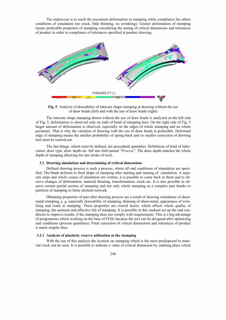
The endeavour is to reach the maximum deformation in stamping while compliance the others conditions of simulation (no crack, little thinning, no wrinkling). Greater deformation of stamping means preferable properties of stamping considering the tuning of critical dimensions and tolerances of product in order to compliance of tolerances specified at product drawing.
Fig. 5 Analysis of drawability of intricate shape stamping at drawing without the use
of draw beads (left) and with the use of draw beads (right)
The intricate shape stamping drawn without the use of draw beads is analyzed on the left side of Fig. 5, deformation is observed only on radii of bend of stamping here. On the right side of Fig. 5 larger amount of deformation is observed, especially on the edges of whole stamping and on whole perimeter. That is why the variation of drawing with the use of draw beads is preferable. Deformed edge of stamping means the smaller probability of spring-back and so smaller correction of drawing tool must be carried out.
The last things, which must be defined, are procedural quantities. Definitions of kind of lubri-cation, draw type, draw depth etc. fall into fold named ”Process”. The draw depth matches the whole depth of stamping (drawing for one stroke of tool).
3.2 Drawing simulation and determining of critical dimensions Defined drawing process is such a process, where all end conditions of simulation are speci-
fied. The blank deforms to final shape of stamping after starting and running of simulation. A sepa-rate steps and whole course of simulation are written, it is possible to come back to them and to ob-serve changes of deformation, material thinning, transformation, crack etc. It is also possible to ob-serve certain partial section of stamping and not only whole stamping as a complex part thanks to partition of stamping to finite element network.
Obtaining properties of part after drawing process are a result of drawing simulation of sheet-metal stamping, e. g. especially drawability of stamping, thinning of sheet-metal, appearance of wrin-kling and crack at stamping. These properties are crucial factor, which affects whole quality of stamping, the usement and effective life of stamping. It is possible in this stadium set up the end con-ditions to improve results, if the stamping does not comply with requirements. This is a big advantage of programmes which working on the base of FEM, because the tool can be designed after optimizing end conditions (process quantities). Final correction of critical dimensions and tolerances of product is much simpler then.
3.2.1 Analysis of plasticity reserve utilization at the stamping With the use of this analysis the location on stamping which is the most predisposed to mate-
rial crack can be seen. It is possible to indicate a value of critical dimension by marking place which
247
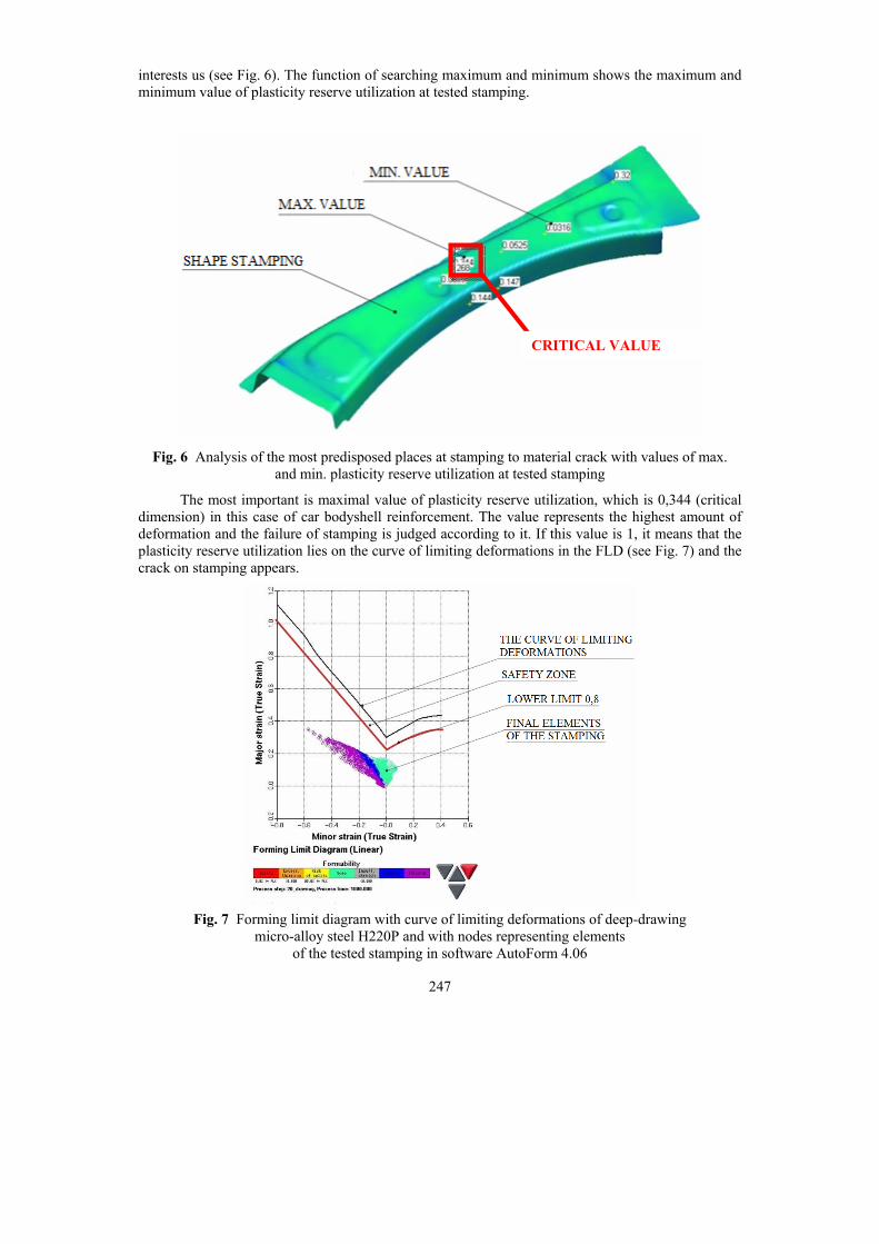
interests us (see Fig. 6). The function of searching maximum and minimum shows the maximum and minimum value of plasticity reserve utilization at tested stamping.
Fig. 6 Analysis of the most predisposed places at stamping to material crack with values of max.
and min. plasticity reserve utilization at tested stamping
The most important is maximal value of plasticity reserve utilization, which is 0,344 (critical dimension) in this case of car bodyshell reinforcement. The value represents the highest amount of deformation and the failure of stamping is judged according to it. If this value is 1, it means that the plasticity reserve utilization lies on the curve of limiting deformations in the FLD (see Fig. 7) and the crack on stamping appears.
Fig. 7 Forming limit diagram with curve of limiting deformations of deep-drawing
micro-alloy steel H220P and with nodes representing elements of the tested stamping in software AutoForm 4.06
CRITICAL VALUE
248
It is advantageous to decrease this criterion from 1,0 to value 0,8 (Fig. 7) because changes of drawing tool may be done while ending correction of critical dimensions and tolerances of stamping in order to compliance tolerances specified at the part production drawing which may affect the de-formation of stamping. If the value of plasticity reserve utilization is set up by this way, enough big play will be secured because others deformations of stamping can be appeared while the tools are correcting and while non-influence-able outside influences are here.
The value 0,344 matches to maximum plasticity reserve utilization at chosen stamping, this value is deep under specified border 0,8, so the stamping matches to this criterion. It can be certified on curve of limiting deformations (see Fig. 7), where the nodes representing elements of tested stamping lie deep under curve.
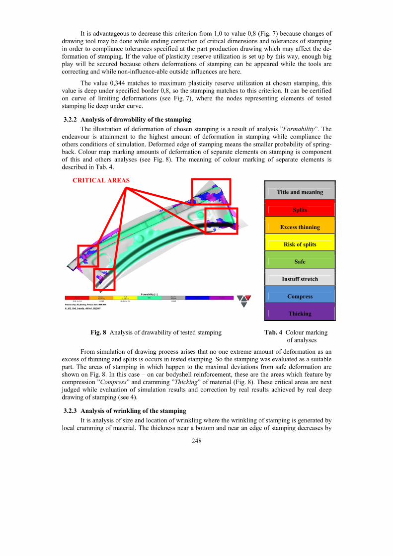
3.2.2 Analysis of drawability of the stamping The illustration of deformation of chosen stamping is a result of analysis ”Formability”. The
endeavour is attainment to the highest amount of deformation in stamping while compliance the others conditions of simulation. Deformed edge of stamping means the smaller probability of spring-back. Colour map marking amounts of deformation of separate elements on stamping is component of this and others analyses (see Fig. 8). The meaning of colour marking of separate elements is described in Tab. 4.
Fig. 8 Analysis of drawability of tested stamping Tab. 4 Colour marking of analyses
From simulation of drawing process arises that no one extreme amount of deformation as an excess of thinning and splits is occurs in tested stamping. So the stamping was evaluated as a suitable part. The areas of stamping in which happen to the maximal deviations from safe deformation are shown on Fig. 8. In this case – on car bodyshell reinforcement, these are the areas which feature by compression ”Compress” and cramming ”Thicking” of material (Fig. 8). These critical areas are next judged while evaluation of simulation results and correction by real results achieved by real deep drawing of stamping (see 4).
3.2.3 Analysis of wrinkling of the stamping It is analysis of size and location of wrinkling where the wrinkling of stamping is generated by
local cramming of material. The thickness near a bottom and near an edge of stamping decreases by
Title and meaning
Splits
Excess thinning
Risk of splits
Safe
Instuff stretch
Compress
Thicking
CRITICAL AREAS
249
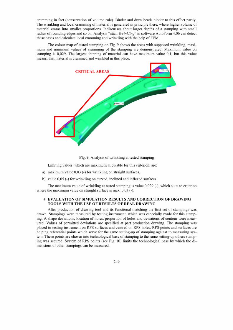
cramming in fact (conservation of volume rule). Binder and draw beads hinder to this effect partly. The wrinkling and local cramming of material is generated in principle there, where higher volume of material crams into smaller proportions. It discusses about larger depths of a stamping with small radius of rounding edges and so on. Analysis ”Max. Wrinkling” in software AutoForm 4.06 can detect these cases and calculate local cramming and wrinkling with the help of FEM.
The colour map of tested stamping on Fig. 9 shows the areas with supposed wrinkling, maxi-mum and minimum values of cramming of the stamping are demonstrated. Maximum value on stamping is 0,029. The largest thinning of material can have maximum value 0,1, but this value means, that material is crammed and wrinkled in this place.
Fig. 9 Analysis of wrinkling at tested stamping
Limiting values, which are maximum allowable for this criterion, are:
a) maximum value 0,03 (-) for wrinkling on straight surfaces,
b) value 0,05 (-) for wrinkling on curved, inclined and inflexed surfaces.
The maximum value of wrinkling at tested stamping is value 0,029 (-), which suits to criterion where the maximum value on straight surface is max. 0,03 (-).
4 EVALUATION OF SIMULATION RESULTS AND CORRECTION OF DRAWING TOOLS WITH THE USE OF RESULTS OF REAL DRAWING
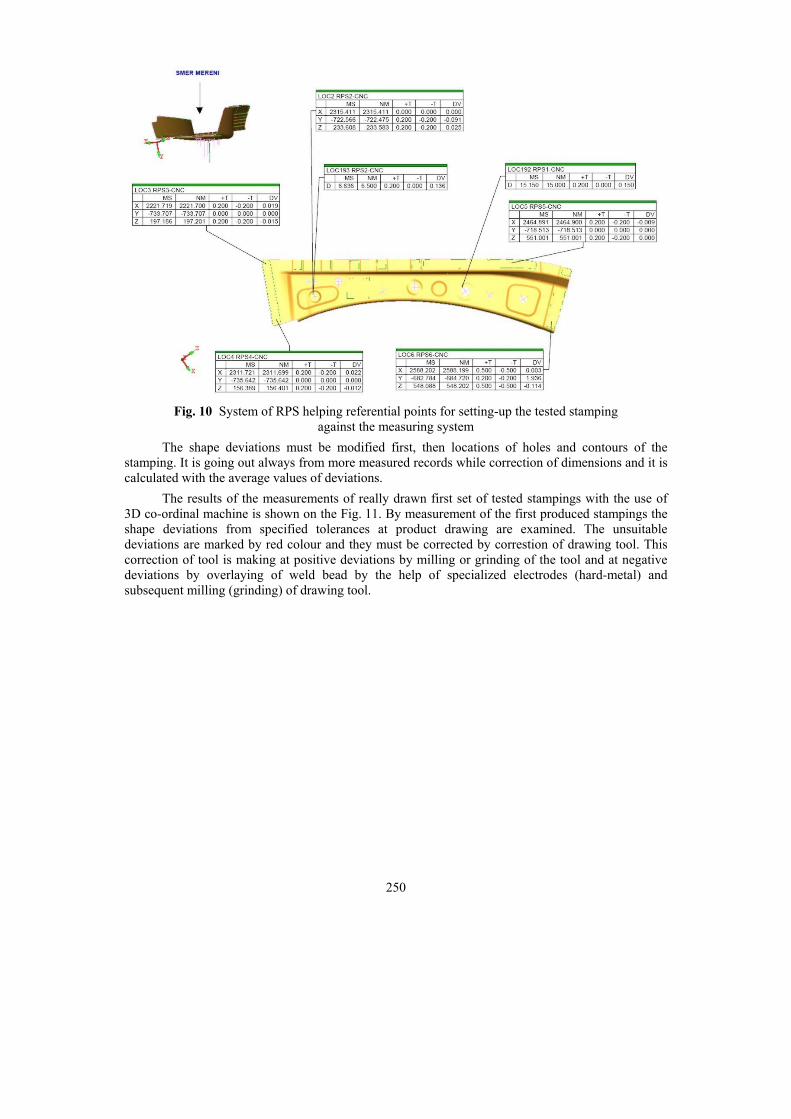
After production of drawing tool and its functional matching the first set of stampings was drawn. Stampings were measured by testing instrument, which was especially made for this stamp-ing. A shape deviations, location of holes, proportion of holes and deviations of contour were meas-ured. Values of permitted deviations are specified at part production drawing. The stamping was placed to testing instrument on RPS surfaces and centred on RPS holes. RPS points and surfaces are helping referential points which serve for the same setting-up of stamping against to measuring sys-tem. These points are chosen into technological base of stamping to the same setting-up others stamp-ing was secured. System of RPS points (see Fig. 10) limits the technological base by which the di-mensions of other stampings can be measured.
CRITICAL AREAS
250
Fig. 10 System of RPS helping referential points for setting-up the tested stamping
against the measuring system The shape deviations must be modified first, then locations of holes and contours of the
stamping. It is going out always from more measured records while correction of dimensions and it is calculated with the average values of deviations.
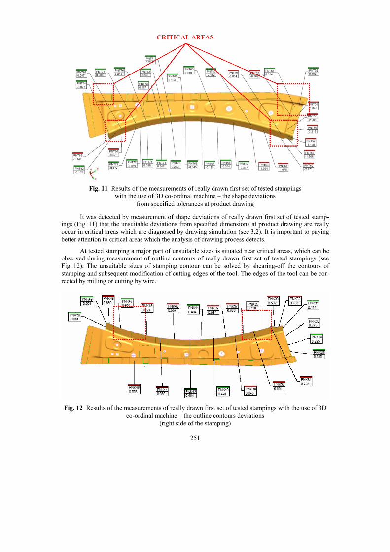
The results of the measurements of really drawn first set of tested stampings with the use of 3D co-ordinal machine is shown on the Fig. 11. By measurement of the first produced stampings the shape deviations from specified tolerances at product drawing are examined. The unsuitable deviations are marked by red colour and they must be corrected by correstion of drawing tool. This correction of tool is making at positive deviations by milling or grinding of the tool and at negative deviations by overlaying of weld bead by the help of specialized electrodes (hard-metal) and subsequent milling (grinding) of drawing tool.
251
Fig. 11 Results of the measurements of really drawn first set of tested stampings
with the use of 3D co-ordinal machine – the shape deviations from specified tolerances at product drawing
It was detected by measurement of shape deviations of really drawn first set of tested stamp-ings (Fig. 11) that the unsuitable deviations from specified dimensions at product drawing are really occur in critical areas which are diagnosed by drawing simulation (see 3.2). It is important to paying better attention to critical areas which the analysis of drawing process detects.
At tested stamping a major part of unsuitable sizes is situated near critical areas, which can be observed during measurement of outline contours of really drawn first set of tested stampings (see Fig. 12). The unsuitable sizes of stamping contour can be solved by shearing-off the contours of stamping and subsequent modification of cutting edges of the tool. The edges of the tool can be cor-rected by milling or cutting by wire.
Fig. 12 Results of the measurements of really drawn first set of tested stampings with the use of 3D
co-ordinal machine – the outline contours deviations (right side of the stamping)

252
The spring-back is solved in correction of simulation with the use of largest amount of defor-mation (see 3.2.2). If the spring-back of stamping appears through that, the problem can be solved by decreasing of angle between stamping and drawing tool so that the specific edge was fitted into the required tolerance specified at part product drawing after spring-back.
After correction of drawing tools according to measurements of really drawn first set of tested stampings compared with all tolerances at part product drawing the tools are ready to expedition or to the stamping shop of the company, if the stampings will be drawn right in this company.
5 CONCLUSIONS It is important to mark critical areas on intricate shape stampings where a sheet-metal is thin-
ning too much and cracking or where the critical areas will affect a shape of tool. These critical areas can be detected with the use of analyses of CAE-software and affect them by the change of end con-ditions of drawing process simulation. Suitable selected end conditions of drawing can suitable affect deformation of stamping (see 3.1.4), it can be prevention of financially expensive modifications of real tool and of subsequent going up in price of drawing tool.
At selected intricate shape stamping – the bodyshell reinforcement the critical areas were diagnosed with the use of software on FEM base. These critical areas can be diagnosed from drawability analysis (see 3.2) which goes out from drawing simulation. The bodyshell reinforcement did not crack during the simulation and also during real drawing and another problems like excessive thinning walls did not appear too, so a measurement of the stamping walls thinning was not carried out.
The measurement of shape deviations and outline curves of really drawn first set of tested stampings was done with the use of 3D co-ordinal machine. The critical areas detected by simulation were compared with this real measurement on 3D measuring centre (see 4). From comparison of measurements at really drawn first set of tested stampings with results of drawing simulation is clear, that critical areas detected by simulation are identical with areas, which must be corrected at drawing tool. So by suitable correction of end conditions during drawing simulations the later time-consuming and financially costlier changes of tool can be prevent from. It is nearly impossible to keep off to these critical areas in cases of deep drawing of intricate shape stampings. With the use of suitable selected simulation with draw beads (see 3.1.4), whether it is a wrinkling of stamping border, spring-back or crack of stamping the behaviour of stamping in drawing process markedly can be affected.
REFERENCES [1] MACHÁLEK, J. Návrh technologie lisování plechové součásti nepravidelného tvaru :
diplomová práce. Ostrava : VŠB-TUO, 2009. 112 s. [2] ČADA, R. Tvářitelnost ocelových plechů : odborná knižní monografie. Lektorovali: L. Pollák
a P. Rumíšek. 1. vyd. Ostrava : REPRONIS, 2001. 346 s. ISBN 80-86122-77-8. [3] FRODLOVÁ, B. Optimalizace napěťových a kinematických poměrů při tažení výtažku
nepravidelného tvaru z tenkého plechu s využitím MKP : diplomová práce. Ostrava : VŠB-TUO, 2009. 247 s.
[4] ČADA, R. Plošná tvářitelnost kovových materiálů. 1. vyd. Ostrava : VŠB–TU Ostrava, 1998. 90 s. ISBN 80-7078-557-8.
[5] HRUBÝ, J., RUSZ, S. a ČADA, R. Strojírenské tváření : skriptum. 1. vyd. Ostrava : Vysoká škola báňská v Ostravě, 1993. 160 s. ISBN 80-7078-201-3.
[6] TIŠNOVSKÝ, B a MÁDLE, L. Hluboké tažení plechu na lisech. 1. vyd. Praha : SNTL, 1990. Bez ISBN.
[7] ČADA, R. a FRODLOVÁ, B. Analysis of elements network influence upon simulation results in the Dynaform 5.2 software. In Sborník vědeckých prací Vysoké školy báňské –Technické univerzity Ostrava : řada strojní. Ostrava : VŠB–TU Ostrava, 2009, roč. 55, č. 1, s. 23-36. ISSN 1210-0471 (Print), ISSN 1804-0993 (Online), ISSN-L 1210-0471, ISBN 978-80-248-2051-4.

253
[8] EVIN, E., HRIVŇÁK, A. a KMEC, J. Získavanie materiálových údajov pre numerickú simuláciu. In Zborník prednášok 7. medzinárodnej konferencie TECHNOLÓGIA 2001 : I. diel. Bratislava : Slovenská technická univerzita v Bratislavě, 2001, s. 281-284. ISBN 80-227-1567-0.
Results in the contribution were achieved at solving of specific research (project ”Technologic Design – Numerical and Physical Simulation“ solved in year 2010) at Faculty of Mechanical Engineering of VŠB – Technical University of Ostrava.

254