j1 joey task support vehicle operator's manual
TRANSCRIPT

DO NOT INSTALL, OPERATE OR SERVICE THIS PRODUCT UNLESS YOU HAVE READ AND FULLY UNDERSTAND THE ENTIRE CONTENTS OF THIS MANUAL. FAILURE TO DO SO MAY RESULT IN PROPERTY DAMAGE, BODILY INJURY OR DEATH.
OPERATOR’S MANUAL
TASK SUPPORT VEHICLE J1 JOEY
WARNING
J1 JOEY Task Support Vehicle. Issue Date: August 13, 2013. Rev.0 (Manual# BGO-J1J-0813)
Do not operate this vehicle unless youhave been authorized and trained todo so, and have read all warnings andinstructions in Operator’s Manual andon this vehicle. Read, understand andcomply with the information on thevehicle’s nameplate at all times.
Do not operate this vehicle until youhave performed the daily operation’scheck list. Verify and inspect tires,horn, battery, controller, lift andhydraulic systems, brakes, steeringmechanism and guards. Verify that allemergency controls, personal protec-tion and safety devices are in placeand functioning correctly and ensurethe vehicle is free of fluid leaks andhas no loose or missing parts. Reportany problems to the designatedauthority and do not use the vehicleuntil they are corrected by a qualifiedmechanic.
This vehicle must not be modifiedwithout the manufacturer’s consent.Components critical to the vehiclesstability such as batteries shall not bereplaced with lighter weight compo-nents.
Operate vehicle only from designatedplatform operating position. Use thisvehicle indoors on level surfaces only.Never operate on ramps and slopesor uneven floors. This vehicle is notfor use on mezzanines or balconyareas. Before operating, inspect thefloor area it will be used on and becertain it will support the vehicle at fullcapacity and lift height. Identify andavoid holes, drop-offs, bumps andobstructions.
Before and during all vehicle opera-tions ensure that adequate clearanceis maintained from overhead obstruc-
tions and energized electrical conduc-tors and parts.
Before elevating platform be sureguardrail access gates are in placeand lowered. Keep feet on platformfloor at all times while using vehicle,never climb onto guard rails or plat-form shelf. Do not use ladders, planksor other devices to achieve additionalheight on platform.
When transferring loads to platform orplatform shelf, do not exceed capacityratings on vehicle nameplate. Ensureloads are centered and do not contactany obstructions in the vehicle’s vicin-ity. Do not stabilize the platform bycontact with adjacent objects such asracks or shelving. Do not use the plat-form as a crane.
Take care to prevent electrical cords,hoses or other equipment from entan-gling in platform. Ensure area sur-rounding the vehicle is free ofpersonnel and equipment before low-ering platform.
Maintain a clear view of the groundwhile travelling and a safe distancefrom obstacles in the vehicle or plat-form’s path. Ensure personnel in thevicinity are aware of the vehicle’smovement. Travel at a safe speed forthe conditions the vehicle is operatingin.
Observe applicable traffic regulations.Yield right of way to pedestrians. Slowdown and sound horn at cross aislesand wherever vision is obstructed.Avoid hazardous locations.
Enter and exit platform only throughraised access gates and with the plat-form fully lowered and vehiclestopped. When leaving vehicle unat-tended, remove key to prevent unau-thorized use.

As an operator, you are responsiblefor a vehicle that is useful, powerful,and can be hazardous if not operatedas described. Observing and adheringto the safety warnings in this manualcannot be overemphasized and isabsolutely necessary for your wellbeing and, for the well being of thosearound you.
It is an OSHA requirement that thismanual and parts and service manualremain with the vehicle at all times asa handy reference guide to operation.
Detailed maintenance procedures arefound in the parts and service manual,and are to be performed only by aqualified technician. For further infor-mation on obtaining a complete partsand service manual, see page 19 ofthis manual.
The operator who knows his/her vehi-cle will learn to spot problems as theydevelop. This is accomplished by per-forming the Daily Operator’s Checklist and reporting any problems to thedesignated authority.
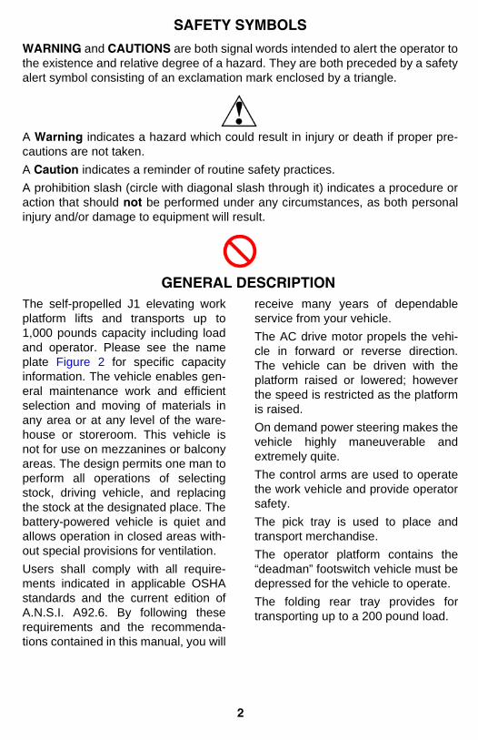
and are both signal words intended to alert the operator tothe existence and relative degree of a hazard. They are both preceded by a safetyalert symbol consisting of an exclamation mark enclosed by a triangle.
A indicates a hazard which could result in injury or death if proper pre-cautions are not taken.A indicates a reminder of routine safety practices.A prohibition slash (circle with diagonal slash through it) indicates a procedure oraction that should be performed under any circumstances, as both personalinjury and/or damage to equipment will result.
The self-propelled J1 elevating workplatform lifts and transports up to1,000 pounds capacity including loadand operator. Please see the nameplate Figure 2 for specific capacityinformation. The vehicle enables gen-eral maintenance work and efficientselection and moving of materials inany area or at any level of the ware-house or storeroom. This vehicle isnot for use on mezzanines or balconyareas. The design permits one man toperform all operations of selectingstock, driving vehicle, and replacingthe stock at the designated place. Thebattery-powered vehicle is quiet andallows operation in closed areas with-out special provisions for ventilation.Users shall comply with all require-ments indicated in applicable OSHAstandards and the current edition ofA.N.S.I. A92.6. By following theserequirements and the recommenda-tions contained in this manual, you will
receive many years of dependableservice from your vehicle.The AC drive motor propels the vehi-cle in forward or reverse direction.The vehicle can be driven with theplatform raised or lowered; howeverthe speed is restricted as the platformis raised.On demand power steering makes thevehicle highly maneuverable andextremely quite.The control arms are used to operatethe work vehicle and provide operatorsafety.The pick tray is used to place andtransport merchandise.The operator platform contains the“deadman” footswitch vehicle must bedepressed for the vehicle to operate.The folding rear tray provides fortransporting up to a 200 pound load.
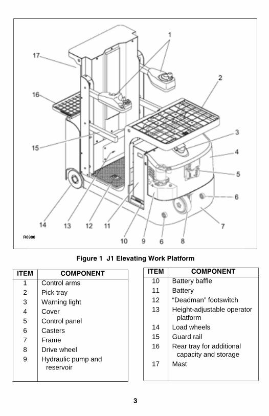
1 Control arms2 Pick tray3 Warning light4 Cover5 Control panel6 Casters7 Frame8 Drive wheel9 Hydraulic pump and
reservoir
10 Battery baffle11 Battery12 “Deadman” footswitch13 Height-adjustable operator
platform14 Load wheels15 Guard rail16 Rear tray for additional
capacity and storage17 Mast

Warning decals are located to the leftof the Instrument panel. The nameplate is mounted on the right side ofthe Instrument panel.
If the name plate or warning decalsare lost or damaged they should bereplaced immediately. Have yoursupervisor or the designated author-
ity contact Big Lift LLC’s AuthorizedDealer for replacement.
The name plate shows the model,serial number, capacity, lift height,vehicle weight and minimum batteryweight. See Figure 2.

Table 1 covers important inspectionpoints on vehicles which should bechecked prior to operation. Dependingon use, some vehicles may requireadditional checks.
Figure 3 shows a sample format foran Operator Checklist, which can bemodified as necessary to fit your oper-ation.
Periodic maintenance of thisvehicle by a QUALIFIEDTECHNICIAN is required.
A QUALIFIED SERVICETECHNICIAN should check thevehicle regularly during preven-tive maintenance for properlubrication, proper fluid levels,brake maintenance, motormaintenance and other areasspecified in the parts and ser-vice manual maintenance sec-tion.
If the vehicle is found to beunsafe and in need of repair, orcontributes to an unsafe condi-tion, report it immediately to thedesignated authority. Do notoperate it until it has beenrestored to a safe operating
condition. Do not make anyunauthorized repairs or adjust-ments. All service must be per-formed by a qualifiedmaintenance technician usingBig Joe OEM pasts.
Preparing the vehicle for operationafter delivery or transport:
1. Check that the equipment is com-plete.
2. Check the hydraulic oil level.Refer to page 18.
3. Install the battery if necessary.
4. Charge the batteries. Refer topage 17.
5. Visually inspect the entire vehiclefor obvious damage.
Operating the vehicle with no load orunder light load conditions for initialuse is recommended. A light load is30 to 50% of the rated load. Duringthe first 100 hours of operationobserve the following:
1. Prevent the new battery fromover-discharging.
2. Perform preventive maintenanceservices carefully and com-pletely.
3. Avoid sudden stops, starts orturns.
4. Perform oil changes and lubrica-tion earlier than specified.

Task Support VehicleDaily Operator Check List
Date
Big Joe Manufacturing Company
Operator
Vehicle No. Model No.
Dept.
Check
Transmission and Hydraulic Systems
Pick Tray and Rear Tray
Control Arms and Guard Rails
Need MaintenanceO.K. ( )
Shift
Safety Warning Labels andNameplate
Horn and Flashing Lights
Emergency Brake Switch
Steering
Hydraulic Controls
Chains, Cables and Hoses
Steering
Travel Controls
Wheels
Battery Disconnect
High Speed Limit Switch
Platform Operation

Transmission and hydraulicsystems
Check for signs of fluid leakage.
Pick tray and rear tray Check for cracks and damage and that it isproperly secured.
Chains, cables and hoses Check that they are in place, properly securedand not damaged.
Control arms and guard rails Check that vehicle operation is disabled whenarms and guard rails are raised.
Safety warning label andnameplate
Check that warning labels, nameplate, etc.,are in good condition and legible.
Horn and flashing lights Check that horn sounds when operated andflashing lights are operable.
Steering Check for binding or looseness in steeringarm when steering.
Travel controls Check that travel control on right control armoperates in all speed ranges in forward andreverse.
Wheels Check drive wheel for cracks or damage.Move vehicle to check load wheels and cast-ers for freedom of rotation.
Hydraulic controls Check operation of lift and lower to their maxi-mum positions.
Emergency power discon-nect switch
Check that brakes actuate when emergencypower disconnect switch is depressed.
Battery disconnect Check that battery can be disconnected andreconnected. Check for connector damage.
Speed limit switches Allow for enough space to operate vehicle inall speeds Test drive the vehicle to check forspeed reductions when elevated. TRIMASTvehicles have three speed reductions, Tele-scopic vehicles have two speed reductions.
Platform Operation Check that all controls in the platform operat-ing compartment are operational.
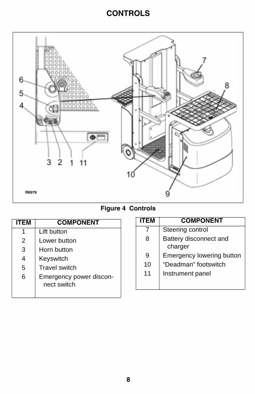
1 Lift button2 Lower button3 Horn button4 Keyswitch5 Travel switch6 Emergency power discon-
nect switch
7 Steering control8 Battery disconnect and
charger9 Emergency lowering button10 “Deadman” footswitch11 Instrument panel

Figure 4)
To raise the platform, push and holdthe LIFT button until desired height isreached. Guard rails need to be inlowered position and “deadman” foot-switch needs to be engaged for traveland lift.
Figure 4)
To lower the platform, push and holdthe LOWER button until the desiredheight is reached. Guard rails need tobe in lowered position and foot pedalneeds to be engaged for travel andlift.
Figure 4)
Sounds the horn.
Figure 4)
The keyswitch has two positions, ONand OFF. Remove the key to preventunauthorized use.
Figure 4)
This switch controls forward, neutraland reverse travel. Travel direction isalso indicated on the instrumentpanel.
Figure 4)
Pushing down the emergency powerdisconnect switch disconnects themain power, deactivates all electricalfunctions, causing the vehicle to brakeautomatically.
Figure 4)
This control is operated in the conven-tional manner. Drive wheel direction isalso indicated on the instrumentpanel.
The battery disconnect can be used tocut off all power to the vehicle. It isalso used to connect the batteries tothe battery charger.
Press this button to lower the platformin case of an emergency.
Operator must stand on this pedal toto activate the controls.
The instrument panel contains the fol-lowing displays and controls:

This LED lights when the measuredbattery voltage is equal or less than40% nominal battery voltage.
When a fault is detected, this LED willlight. The display (7, will dis-play the warning and fault indication.Report alarm to the designatedauthority and do not use the vehicleuntil corrected by a qualifiedmechanic.
When the temperature of the drivemotor is too high, the LED will illumi-nate. Temporarily stop operation until
the temperature drops and notify anauthorized technician.
When the drive pedal is released, thisLED will illuminate.
This LED will illuminate when theemergency brake switch is actuated.
Use the left arrow button to adjust thespeed mode. Use the down arrow but-ton to switch the driving mode.
The display has the following func-tions:

Thestate of charge is displayed by tennotches. Each notch represents 10%of the battery charge. For example,the illustration shows the battery has80% charge.
Displays the warnings and faults.Report warnings and faults to the des-ignated authority and do not use thevehicle until corrected by a qualifiedmechanic.
Indi-cates the vehicle’s speed.
The vehicle can be operated in twodriving modes, high speed or crawlspeed. Use the “down” function key(6, Figure 5) to switch the drivingmode:
There are four speed ranges availablein both the high speed driving modeand the crawl speed driving mode.Use the “left” function key (6, Figure5) to select the desired mode. “1” indi-cates the slowest speed while “4” indi-cates the highest speed.
When the platform rises thevehicle automatically enterscrawl speed.
Oneof nine notches will indicate the steer-ing angle of the drive wheel.
.
.
The vehiclemay only be used by trained person-nel, who have been authorized tooperate the vehicle by the supervisoror the designated authority.
Theoperator must be informed of hisduties and responsibilities and betrained in the operation of the vehicleand shall be familiar with the opera-tor’s manual.
Theoperator is responsible for the vehicleduring the time it is in use. He/sheshall prevent unauthorized personsfrom driving or operating the vehicle. Itis forbidden to carry passengers or tolift personnel.
The supervisoror the designated authority must beimmediately informed of any damageor fault codes. Vehicles not safe foroperation must not be used until theyhave been repaired.
The operator must not carryout any repairs or alterations to thevehicle. The operator must never dis-able or adjust safety mechanisms orswitches.
A hazardous area isdefined as the area in which a personis at risk due to vehicle movement, lift-ing operations, or the load itself. Thisalso includes areas which can bereached by falling loads or loweringEquipment.
• Unauthorized persons must be keptaway from hazardous area.
• Where there is danger to personnel,a warning (the horn) must besounded with sufficient notice.
• If unauthorized personnel are stillwithin the hazardous area the vehi-cle shall be brought to a halt imme-diately.
Safety devices, warning signs andwarning instruction shall be strictlyobserved.
The vehicle can be driven with theplatform raised or lowered; however,the speed is restricted when the plat-form is raised above a preset limit.
Changes to the pre-set controlparameters are not permitted w/oexplicit written permission from themanufacturer, Big Lift LLC.
Do not leave the platform cagefloor area while the operatorplatform is elevated. Do notlean out from the outside of acage rail. Climbing on the guardrails and/or trays is strictly pro-hibited and can lead to severeinjury or death.
Only one person is permitted inthe operator’s compartment atall time.

Proceed as follows to start and stopthe vehicle.
1. Step on the operator platformwith you back against the backrest.
2. Lower the control arms and guardrails.
3. Turn on the keyswitch (4, Figure7) and pull up on the emergencypower disconnect switch (6, Fig-ure 7).
4. Step on “deadman” footswitch(10, Figure 7) to activate the elec-trical controls.
5. Adjust the driving mode (4, Fig-ure 6) using the “down” key (6,Figure 5).
6. Select the speed mode (5, Figure6) using the “left” function key (6,Figure 5).
7. Use the steering control (7, Fig-ure 7) to steer the vehicle in therequired direction. Drive wheeldirection is indicated on theinstrument panel.
8. Using your right hand, move thetravel switch (5, Figure 7) to thedesired direction.
The vehicle is equipped with alevel sensor. When the vehicleis elevated and on a slopegreater than 0.5 degree, thelevel sensor sounds an alarmbeeper. The truck is only to beused indoors on a level surface.This vehicle is not for use onmezzanines or balcony areas.
The brake pattern of the vehicledepends largely on the ground condi-tions. The driver must take this intoaccount when operating the vehicle.The driver must be looking aheadwhen traveling. If there is no hazard,brake moderately to avoid moving theload.
The vehicle can brake in three differ-ent ways;
release the drivepedal (10, Figure 7) and allow thevehicle to coast to a stop.
To stop faster,slowly move the travel switch (5, Fig-ure 7) to the opposite direction.
The vehicle direction may bereversed while moving. Thecontrol will cycle the motor tostop and then reverse in atimed sequence without dan-ger to the equipment. Exer-cise caution when doing so,especially when traveling atmaximum speed.
To stop rapidlywhen an emergency exists, press theemergency brake switch (6, Figure 7).
Except in an emergency, do notstop suddenly.

Ensure there are no other peo-ple standing underneath theraised platform. Instruct otherpeople to move out of the haz-ardous area.
Press and hold the lift button(1, Figure 7) until you reach thedesired height.
Never raise the guard railswhen the vehicle is in an ele-vated position.
Press and hold the lowerbutton (2, Figure 7) until you reach thedesired height.
Lowering, the vehicle soundsan intermittent alarm beeper.
If a condition exists where loweringwithout power is necessary, instructsomeone on the ground to push sole-noid valve button (1, Figure 8) throughhole (9, Figure 7).
Do not leave the platform cagefloor area while the operatorplatform is elevated. Do notlean out from the outside of acage rail. Climbing on the guardrails and/or trays is strictly pro-hibited and can lead to severeinjury or death.

1. Drive the vehicle carefully up tothe storage location (4, Figure 9).
2. Press the lift button (1) until picktray (3) reaches the desiredheight.
3. Move the load from storage loca-tion (4) to tray (3).
4. Press the lower button (2) untilthe platform is completely low-ered.
1. Always transport load with theplatform completely lowered.
2. Always transport loads on thepick tray or the rear tray.
3. Always be prepared to brake.Only stop suddenly in emergencysituations.
4. Reduce speed in tight areas.

1. Drive the vehicle carefully up tothe storage location (4, Figure 9).
2. Press the lift button (1) until picktray (3) reaches the desiredheight.
Ensure storage location is suit-able for storing the load (sizeand capacity).
3. Move the load from tray (3) tostorage location (4).
4. Press the lower button (2) untilthe platform is completely low-ered.
When performing overhead mainte-nance, please ensure there are noobstacles, beams or other obstruc-tions before elevating lift. Always fullylower the platform before moving tothe next maintenance position.Ensure a safe work environment
before proceeding with maintenanceand never operate the lift outside.
When leaving the vehicle, it must besecurely parked even for a short time.
1. Park the vehicle in its designatedparking area.
Do not park the vehicle on aslope. The platform must becompletely lowered.
2. Lower the platform completely.
3. Set the emergency power discon-nect switch to apply the brake.
4. Turn keyswitch to off position.Remove key for added security.
5. Pull out battery disconnect.
Do not attempt to move a disabledvehicle; notify your supervisor orproper authority.

Securely park and disable the vehiclebefore carrying out any work on thebatteries.
Refer to Supplement 245 for batterysafety and maintenance.
Batteriesmay only be charged by trained per-sonnel. Service and replacement mayonly be performed by your Big LiftDealer.
• Smoking and open flames must beavoided when working with batter-ies.
• The area must be well vented.
• Fire protection equipment must beprovided.
The batterycell covers must be kept dry andclean. The terminals must be clean,secure and have a light coating ofdielectric grease. Batteries with noninsulated terminals must be coveredwith a non slip insulation mat.
Wear glasses for eye protec-tion. Wear rubber overshoes,protective wear and rubbergloves when servicing batter-ies.
If batteries aretaken out of service for a lengthyperiod of time they should be stored inthe fully charged condition in a dry,frost-free room.
Before charging, check all cables andplug connections for visible signs ofdamage.
It is essential to follow the safety regu-lations of the battery and charger.
1. Park the vehicle at charging sta-tion with platform lowered andkeyswitch OFF.
2. Apply the emergency parkingbrake.
3. Disconnect plug (1, Figure 6)from the vehicle and connect it tocharger’s plug (2).
4. Connect cord (3) and charge thebattery according to Supplement374 .
Please refer to the Big Joe Support site at www.bigjoesupport.com

Refer to Table 2 for the recommendedtypes of grease and oil. Table 3 inconjunction with Figure 11 identifiesthe items requiring lubrication. No. 1 Grease—Polylub GA352P.
No. 2 Hydraulic oil-L-HM46#
1 Mast Spray No. 1 Full length of channelwhere rollers oper-ate.
2 HydraulicReservoir
Can No. 2 With platform fullylowered, fill reser-voir with hydraulic oilto level on dip stick.

A complete parts and service manual covering this vehicle is available from BigLift LLC. To order, obtain the serial number of your vehicle and contact your BigJoe Authorized Dealer. You may also visit www.bigjoesupport.com.

NOTES

NOTES

B L U E G I A N T E Q U I P M E N T C O R P O R AT I O N
© 2012 Big Joe by Blue Giantif calling within North America:Phone: 1-800-668-7078 Fax: 1-888-378-5781
85 Heart Lake Road SouthBrampton, Ontario, Canada L6W 3K2Phone : 905-457-3900 Fax : 905-457-2313www.BlueGiant.com