j. lima-de-faria et al. 11
TRANSCRIPT

J. LIMA-DE-FARIA et al. 11
HAHN, TH., KUCHITSU, K. & ABRAHAMS, S. C. (1984). Acta Cryst. A40, 399-404.
HAWTHORNE, F. C. (1983). Acta Cryst. A39, 724-736. HELLNER, E. (1965). Acta Cryst. 19, 703-712. HELLNER, E. (1986). Z. Kristallogr. 175, 227-248. HELLNER, E., KOCH, E. & REINHARDT, A. (1981). The
Homogeneous Frameworks of the Cubic Crystal Structures. Physics Data, Vol. 16-3. Karlsruhe: Fachinformationszentrum.
HELLNER, E. 8z. SOWA, H. (1985). The Cubic Structure Types Described in their Space Groups with the Aid of Frameworks. Physics Data, Vol. 16-3. Karlsruhe: Fachinformationzentrum.
HERMANN, C. (1960). Z. Kristallogr. 113, 142-154. HOPPE, R. (1979). Z. Kristailogr. 150, 23-52. HYDE, B. G., ANDERSSON, S., BAKKER, M., PLUG, C. M. &
O'KEEFFE, M. (1979). Prog. Solid State Chem. 12, 273-327. International Tables for Crystallography (1983). Vol. A, 1 st ed. (2nd
ed., 1987), edited by TH. HAHN. Dordrecht: Reidel. (Present distributor Kiuwer Academic Publishers, Dordrecht.)
IUPAC (1990). Nomenclature of Inorganic Chemistry. Oxford: Blackweli.
LAVES, F. (1930). Z. Kristallogr. 73, 202-265, 275-324. LAVES, F. (1980). Z Kristallogr. 151, 21-29. LIEBAU, F. (1982). Rev. Mineral. 5, 1-24. LIEBAU, F. (1985). Structural Chemistry of Silicates. Structure,
Bonding and Classification. Berlin: Springer. Russian ed. Struk- turnaya Khimiya Silikatov. Moscow: Mir, 1988.
LIMA-DE-FARIA, J. (1965). Z. Kristallogr. 122, 346-358, 359-374.
LIMA-DE-FARIA, J. & FIGUEIREDO, M. O. (1976). J. Solid State Chem. 16, 7-20.
LIMA-DE-FARIA, J. & F1GUEIREDO, M. O. (1978). Garcia de Orta, S6r. Geol. 2, 69-76.
MACHATSCHKI, F. (1928). Centralbl. Miner. Geol. Paliiont. Abt. A, pp. 97-104.
MACHATSCHKI, F. (1947). Monatsh. Chem. 77, 333-342. MACHATSCH KI, F. (1953). Specielle Mineraiogie aufgeochemischer
Grundlage (esp. pp. 298-353). Wien: Springer. MAKOVlCKY, E. (1981). Fortschr. Mineral. 59, 137-190. MAKOVlCKY, E. (1985). Fortschr. Mineral. 63, 45-89. MAKOVICKY, E. & HYDE, B. G. (1981). Non-commensurate
(Misfit) Layer Structures. In Structure and Bonding, Vol. 46, pp. 101-175. Berlin: Springer.
NIGGL1, P. (1919). Geometrische Kristallographie des Diskon- tinuums. Leipzig: Borntr~iger.
N1GGLI, P. (1945). Grundlagen der Stereochemie. Basel: Birk- h~iuser.
O'KEEFFE, M. (1979). Acta Cryst. A35, 772-775. O'KEEFEE, M. & HYDE, B. G. (1980). Philos. Trans. R. Soc.
London, 295, 553-623. PARTHE, E. (1980). Acta Cryst. B36, 1-7. PARTHI~, E., CHABOT, B. A. & CENZUAL, K. (1985). Chimia, 39,
164-174. PARTH~, E. & GELATO, L. M. (1984). Acta Cryst. A40, 169-183. SMITH, J. V. & DYTRYCH, W. J. (1986). Z. Kristallogr. 175, 31-36. ZVYAGIN, B. B. (1987). Soy. Phys. Crystallogr. 32, 394-399.
Acta Cryst. (1990). A46, 11-32
Bloch Waves and Multislice in Transmission and Reflection Diffraction
BY Y. MA AND L. D. MARKS
Materials Research Center, Northwestern University, Evanston, IL 60208, USA
(Received 6 March 1989; accepted 3 August 1989)
Abstract
The consistency between Bloch-wave and multislice approaches to calculating high-energy electron diffraction is investigated in both transmission and reflection cases, the emphasis being upon the latter. It is first shown, in more detail than previously pub- lished, that in transmission the two yield identical results. Next, the Bloch-wave approach for reflection is shown to yield a stationary solution in multislice, except for a small effect from the surface truncation. It is pointed out that the multislice approach can be exploited to solve exactly for the reflected wave for an arbitrary surface potential by using it as a Picard iteration solution of the Schr6dinger equation. The surface potential scattering is not incidence-angle related and is not significant as might be expected. The introduction of absorption improves the con- sistency between the two methods. Finally, the stationary solutions are compared with solutions obtained using a top-hat incident wave. The latter approach leads to partially stationary solutions, although it is very hard to identify these.
0108-7673/90/010011-22503.00
I. Introduction
The history of surface investigations by reflected high- energy electrons can be traced back to the early development of electron diffraction. It has developed both theoretically and experimentally in different directions: imaging (RHEEM), diffraction (RHEED) and electron energy-loss spectroscopy (RHEEL). The combination of these techniques promises to be a powerful tool for studying crystal surface structures, particularly for in situ study of molecular beam epi- taxy (MBE) by RHEED (Harris, Joyce & Dobson, 1981a, b; Wood, 1981) and surface inhomogeneities by RHEEM (Cowley & Nielsen, 1975; Osakabe, Tanishiro, Yagi & Honjo, 1981; Hsu, 1983; Hsu & Cowley, 1983, etc.).
With the development of experiments in this field, tremendous efforts went into the development of a dynamical theory. Not long after Ewald (1917) first established the dynamical theory for X-ray diffrac- tion, Bethe (1928) developed the dynamical theory for electron diffraction in a crystal, in which the reflection geometry was briefly discussed. With the
© 1990 In te rna t iona l Un ion of Crys ta l lography

12 BLOCH WAVES IN TRANSMISSION AND REFLECTION DIFFRACTION
development of electron-microscope techniques in the late 1950's, the Bethe theory (also called Bloch- wave theory) was widely applied in transmission elec- tron microscopy (Whelan & Hirsh, 1957; Kato, 1952; Fujimoto, 1959). Theoretical development for the reflection case (both RHEED and RHEEM) has been rather slow. In 1954, Miyake, Kohra & Takagi applied the Bethe formulation to explain the anomalous enhancement of specular reflection in RHEED. Several years later, Kohra, Mokiere, Nakano & Ariyama (1962) used a similar method to calculate the intensity of the specular reflection from a single- crystal surface for a finite number of beams, trying to interpret anomalous intensities in RHEED. In both of these studies, the problem of determining the excited wave points in the crystal was discussed. However, how to choose the wave points in the gen- eral case, which is important for calculations with a large number of beams, was not given. In the early 1970's, Coleila (1972) and Moon (1972) attempted to extend the Bethe formulation to n-beam dynamical RHEED. To avoid the problem of determining excited wave points, they considered the crystal as a slab which had a finite thickness. Very recently, we introduced the argument of current flow for the reflection case (Marks & Ma, 1988; Ma & Marks, 1989) and cleared up the confusion around the wave points in the band gap (evanescent wave) and the wave points which are not excited in the crystal and were able to solve the general n-beam problem.
However, the basic limitations in the Bloch-wave method are not removed so easily; when a large number of beams is used, the computation speed is slow, and the method is also not readily available to simulate surface defects. Various alternative methods have therefore been proposed. The column approxi- mation was introduced by Shuman (1977), where the column is taken to be normal to the surface and the beam. The validity of the approximation has been proved to be very limited. Later, by making use of the 'slice concept', Maksym & Beeby (1981, 1982) and Ichimiya (1983) developed a multislice dynami- cal theory for the reflection case, in which thin slices of the crystal are taken to be parallel to the crystal surface. This method is suitable for surface-layer defects parallel to the surface, such as stacking faults and surface potentials. Very recently, Peng & Cowley (1986) utilized a multislice method with slices perpen- dicular to the surface. This approach is apparently suitable for various crystal defects because the poten- tial of each slice can be constructed with high flexibil- ity. However, the difficulty is that the incident wave is taken as a top-hat function (with smooth sides) that is allowed to impinge upon the surface, and it is hard to reach a stationary solution (as dictated by the symmetry in reflection) since the size of the input incident wave is limited and edge effects are unavoid-
able. The computation speed is slow when the incident-beam number is large.
Each of the above methods has its own problems and limitations, but, theoretically, they should be consistent with each other. This suggests that it is possible to combine different methods and provide a much more powerful approach. In addition, investi- gation of the consistency "between different methods and the conditions for this provides a clear-cut mutual proof of both methods and may reveal more physical information about the interaction of electrons with crystals.
In this paper, we report the results of combining the Bloch-wave and multislice methods (slices normal to the beam) for reflection diffraction. Firstly, we discuss consistency between the two in transmission diffraction, a necessary precursor to the reflection problem. Next, we show that the Bloch-wave approach yields a stationary solution for the multi- slice, albeit with a small effect from the surface trunca- tion. In the process, it is pointed out that the multislice method can be exploited as a Picard iteration to yield an exact solution for arbitrary surface potentials. Finally, we compare these results with the results obtained using the approach of Peng & Cowley (1986).
i i . Numerical method
The scheme of the program combining the Bloch- wave and multislice approaches is shown in Fig. 1. The program consists of two blocks: one for the Bloch-wave calculation and the other for the multi- slice calculation. The Bloch-wave calculation for the reflection case has been discussed in detail previously. The multislice calculation is based on the multislice
Xo(R) ",, / Zero Laue-zone • ~ for THEEM
, " i;-:
Zero L o u ~ zone for RHEEM
. ~ o ° ° . - - | . . . . . .
Fig. 1. The scheme of the p rog ram combin ing the Bloch-wave and multislice approaches . Xo(R) denotes the incident wave vector in the reflection case and Xo(T) denotes the incident wave vector in the t ransmiss ion case. The zero Laue zones for the two cases are pe rpend icu la r to each other.

Y. MA AND L. D. MARKS 13
programs developed by one of us (LDM), which is currently used for high-resolution THEEM simula- tion at Northwestern University. (The same programs in an earlier form were modified by Peng for multislice reflection calculations.) The Bloch-wave block can be operated in both THEEM and RHEEM modes, the only difference being the angle of the incident beam with respect to the crystal surface. The input of the multislice block is the output from the Bloch-wave block.
III. Consistency in THEEM
Prior to combining the two approaches for reflection diffraction, one should know whether they are con- sistent or not; at what stage they are; and for what conditions they are. In addition, the investigation can also offer information about the reliability of the programing. We will briefly present our results here which confirm the earlier work of Self, O'Keefe, Buseck & Spargo (1983), although we will provide a little additional detail.
Fig. 2 shows plots of the amplitude and phase of the (100), (200) and (440) beams versus thickness for gold along [001] using 100 keV electrons. A couple of points should be clarified:
(i) The oscillation periodicities of both the ampli- tudes and the phases for different beams in our result are systematically a little smaller than those reported by Self et al (1983). We suspect that this may be due to different ways of calculating the scattering factor. In our calculation the parameters for X-ray scattering factors are used. The error arising from this term was recently discussed by Peng & Cowley (1988).
(ii) The sign of the phase in our plots is opposite to that of Self et al. (1983); this is possibly due to a different choice of zero reference point - we have taken the (000) beam as the reference point.
(iii) The number of beams for both methods does not include the forbidden beams for the f.c.c, struc- ture; therefore, for the case of the 3 x 3 beam, the actual number of beams calculated is 5 × 5 in the multislice calculation.
(iv) The differences between the matrix method and the multislice method are significant when only a small number of beams are included in the calcula- tion. As Self et al. (1983) pointed out, the reason for those differences is mainly the different normaliz- ation. For this reason, the multislice wave field is normalized at each slice.
(v) In order for the two methods to agree, it is necessary that the potential should be the same for both. For this reason we have ignored all higher-order Laue-zone diffraction in both methods, using only the potential obtained by projecting along the beam direction. As is well known, this may be a severe approximation but otherwise the Bloch-wave compu- tations would be unreasonably slow.
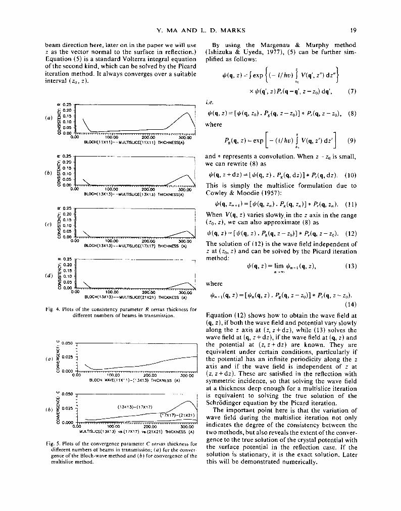
It is important to verify the convergence of both methods. Fig. 3 shows the charge density at various depths for both methods as a function of the number of beams used. Fig. 3 clearly shows that the con- sistency between the Bloch-wave solutions with 13 × 13 beams and the multislice solutions with 21x21 beams is significantly better than that between the Bloch-wave solutions and the multislice solutions both with 13 x 13 beams. To be more quantitative, Fig. 4 shows plots versus thickness of a parameter R ( t ) , where R ( t ) is defined as
~, [ lb,(x, y ) - 1,,,j(x, y)]2
R#( t ) = x,;, ( 1 ) • E lbi(x, y)2 ,
x,) . '
where lbi and lr, j denote the intensities calculated from the Bloch-wave method and the multislice method independently, t is the thickness, and the subscripts i and j denote the number of beams. The curves show that when the number of beams is larger than 11 × 11 the quantitative agreement is excellent. (It is worth pointing out that in order to obtain this agreement some attention had to be paid to reducing numerical errors in the Bloch-wave calculations.) Fig. 5 shows values of a convergence parameter C ( t ) versus thickness for different numbers of beams, where C ( t ) is defined as
I q~,, (x, y ) - q~, (x, Y)I
C~.( t ) = ' " (2) E I c l ' m ( x , y ) + ~ , ( x , y ) [ ' x. y
where q~,,, and q~,, denote the amplitude at each point in the image, and subscripts m and n denote the number of beams for the calculation. The result shows that the magnitude of C,~;,~(t) for the Bloch-wave calculation is close to the magnitude of C,~,~( t ) for the multislice calculation. This means that the Bloch- wave calculation converges at a smaller number of beams than the multislice. The curve C{~;~(t) demon- strates that the multislice calculation converges well enough when the number of beams is larger than 17 × 17. [The monotonic increase of C ( t ) with thick- ness is due to numerical error accumulation.]
IV. Consistency in reflection
In reflection it is difficult to investigate the consistency between the Bloch-wave method and multislice iter- ations since it is difficult to obtain and verify a station- ary solution from the multislice calculation. However, the wave field both inside and outside the crystal in the plane parallel to the zero Laue zone should be constant if the azimuth of the incident beam with respect to any symmetry plane passing through the Laue-zone axis is zero. This provides an alternative

14 BLOCH WAVES IN T R A N S M I S S I O N AND R E F L E C T I O N D I F F R A C T I O N
way of studying the consistency in the reflection mode: using a symmetric incidence condition and taking the output wave from the Bloch wave as the input wave for the multislice block. However, there are basic differences between the Bloch-wave and multislice methods. One is a methodical difference and another is due to the surface truncation, i.e. a zero-surface-potential approximation in the Bloch- wave calculation. The analytical investigation of the methodical relation between the two methods due to lshizuka & Uyeda (1977) is valid for both cases. However, for the special case of reflection it merits further discussion since it turns out that we can exploit the multislice method to provide an exact solution including all the effects of the surface truncation.
To derive the important relationships, we start by considering the integral form of the Schr6dinger equation:
0(r) = exp ( ik . r)
+ ( - 2 m / h 2) J G ( r - r') V(r ' )0(r ' ) dr' (3)
where
G ( r - r ' ) - - exp ( i k l r - r ' l ) / I r - r'l (4)
is the Green function, k is the wave vector of the incident electrons, V(r) the potential energy. Equation (3) can be expressed as:
O(r) = O(q, z ) = .[ O(qo, zo)Pr(q-qo, z - Zo) dqo
+ ( - i /hv) :J V(q', z')q/(q', z') zo
x P,(q - q ' , z - z') dz' dq', (5)
where q = (x, y) is perpendicular to the incident wave vector k, i.e. the z axis, and
P,(q, z) = exp [ikz(1 + q 2/z2)~/2]/iAz(1 + q12/z2) ~/2
(6)
is the Rayleigh-Sommerfeld propagator (Gaskill, 1978) which is also used in the multislice method. (It should be noted that although we are using z as the
(i) B l o c h w a v e l . ~ . a 6 , = , = A l J ~ . , = ~
,.oo I~ 0.75 , ',, ," " ' , . I " "
(a) oso , , " 0.25
°°°o.~' . . . . . . . . . ~ ...... ~o".~"
0 . 5 0 - -
(b) 0 .30
0 .20 , . , , , . ,
o. lo
o . O O o ~ . . . . . . . . . ~ , ~ . . , • 100 .00 200 .00 3 0 0 . 0 0
180.00
(c) o•oo
- ,= .OOo. ~ . . . . . . • . . . . . . .
No. of beam:
100 .00 200.00 5 0 0 0 0
3 X 3 tlA)
(ii)
(a )
M u l t i s l i c e ...............
1 . 0 0
0 .75
0.50
° ° ° o ~ . . . . . ~o"./~-'
(b)
(c)
(d)
(e)
U ..7 -I 0.00 100.00 200•00 300.00
o.oa -7 0 .05 [
o : o .0o . . . . . . . . . .,'. . . . . ; . . . : : : . . . . . . . . . . . . . . . . : . . . . . . . =
o.oo oo.oo 2odoo .... ~'~'"
~ ~ :1 / - . _ J ~ ' - - ~ ' ~ - - ~ ~ - ' ~ - ' ~ ";~ "~" °'°" "°" " " "~i
°°° 1 ! - , a o o o ! ..... ,:.,,; ..... ,,¢Y',~-~,...-4~,.. .... ~ . ~ " ~ i
5 X 5
Fig. 2. Plots of the amplitude and phase of the (100), (200) and (440) beams v e r s u s thickness for gold along [001] in the transmission case using 100 keV electrons: (i)-(vi) show the results for different numbers of beams and each diagram in (i)-(vi) contains two curves for the same condition calculated by the two methods separately. (a), (b) and (d) are plots of the amplitude of (100), (200) and (400) beams and (c) and (e) are plots of the phase of (200) and (400)•

Y. M A A N D L. D . M A R K S 15
(iii) ~.oo , , ,
(a) o.7s
o . % ~ . . . . . ~ . , . ~ - ,
(b) o.2s
0 . 0 0 ~ . , - . _ , : . _ - , : - , ,~ o.oo I o o . o o 200.00 , ~ o . o o
(iv)
(a)
(b)
,, ,, ".
0.75
o ,o ] . . . . . . . . . . . . . . . . . . . . . . . . . . I o . . , ~ . ~ , 2 ~ , . ~ ~ . .
0 . 2 5
0 . 0 0 0.00 100.00 200.00 300.00
, , , , , , , , , . . . . , , , , , , ~ , , , . , , , , , , , , . ~ , . , , , | , , , , , , , , , , , , , , , . . . . ! , , , , , -18o.oo o.oo 1 oo.oo 2oo.oo 300.00
0 . 0 8
. , , , , , , , , , , , , , , , , , , , i , , , , , , t , , , , , , , , , , , , , , , , , , , , , , , , , , , , , , , i , , ,
(d)
180.00 7- - - i ' - - - - - i J - - - - . z~ . . ~, ~ ",.,~ ,,,.4 ..,.,4- 1
- o.& ............... ;88'.~ ............ ~88.~o" ................ . .....
9X9
(v) I.oo
(a) o.Ts
0.50 0.00 100.00 200.00 300.00
0.50
( b ) 0.25
0.00 ' 0.00 100.00 200.00 300.00
, . . o o / . / / / 1 / ] c o.K;" ; , , ,,,. - 180 .00 . . . . . . . . . . . . . . . . . . . • . . . . . . . . . . . . . . . . . . . . . . . . . . . . . . . . . . . . . . , . . . . .
0.00 100.00 200.00 3 0 0 . 0 0
0 . 0 8
0 . 0 3 i
0.00 | ~ , , - . . . . . f:._,,_,_,,~ 0.00 100.00 200.00 300.00
(d)
" ° ° ~ - C - / ' / "/ / "~ ~ ' l
(e ) 0.oo t " I
0 . ~ 11:~.IX) 2 ~ . ( ~ 3 0 0 . 0 0
13 X 13
/ / . A - 1 8 0 . 0 0 , . . . . . . . . . . . . . . . . . . . . . .
1 0 0 . 0 0 3 0 0 . 0 0 o.oo . . . . . . . . . . . . ' i ~ ' . ~ . . . . . . . . . . . . . . . . . . . . . .
0 . 0 8
0 . 0 3
o . o o ~ . . . . . . ~ ; ~ - , 0.00 " ,00 .00 . •
( d )
( e ) o . o o
. . . . . . . .
0 . 0 0 100.00 200.00 3 0 0 . 0 0
I I X I I
(vi) 1.oo
(a) o 7 5
0.50 o.oo 1oo.oo 200.00 3 0 0 . 0 0
(b) o.2s
0.00 0.00 100.00 200.00 300.00
( c ) o . o o " • " : "
, _ ! / / / 0.00 100.00 200.00 300.00
0.08
0 . 0 3
o . o o , . , , , , , , , , , , , , , , . , , , . . , . , . , , . , . , . , . , , , i , , , , . , . , , , , , , , , , , , , i , , . . o.0o 100 oo 200 OO 300 O0
(e) o.oo
o.00 1 oo.o0 2oo.oo 300.00
B l o c h w a v e : 13Xl3 M u l t i s l i c e : 17X l7
F i g . 2 (cont . )

16 B L O C H W A V E S I N T R A N S M I S S I O N A N D R E F L E C T I O N D I F F R A C T I O N
(a) (c) (e) (g)
(b) (d) ( f ) (h)
II X II
13X 13 (i)
Fig. 3. Current density outputs at various depths for (i) the Bloch-wave method and (ii), (iii) the multislice method as a function of the number of beams in the transmission case. The thicknesses from (a) to (h) are: 20.2, 40.5, 121.5, 162-0, 202.5, 243.0, 303.7, 324.0 .~.

Y. M A A N D L. D. M A R K S 17
I I X I I
13 X 13 (ii)
Fig. 3 (cont.)

18 BLOCH WAVES IN TRANSMISSION AND REFLECTION DIFFRACTION
(a) (c) (e) (g)
(b) (d) (f) (h)
17 X 17
2 IX 21 (iii)
Fig. 3 (cont.)
Y. MA AND L. D. MARKS 19
beam direction here, later on in the paper we will use z as the vector normal to the surface in reflection.) Equation (5) is a standard Volterra integral equation of the second kind, which can be solved by the Picard iteration method. It always converges over a suitable interval (zo, z).
0 . 2 0
(a) ~ o.15
-- 0.,0
~ 0.05 0.00 ,,~ . . . . . . . . . " . . . . . . ~ , . . . . . . . . . . . . . . . . . . . c . . . . . . . ,~ . . . . . . . . . . , . . . . [
0 . 0 0 100.00 2 0 0 . 0 0 300.00 BLOCH(11 X 11 ) - -MULTISUCE(11 X 11 ) THICHNESS(A)
x 0.25
"i 0 . 2 0 0 . 1 5
(b) 0 . 1 0
0.05
0 0.00 . . . . . . . . . . . . . . . . . . . , . . . . . . . . . . . . . . . . . . . , . . . . . . . . 0 . 0 0 1 0 0 . 0 0 2 0 0 . 0 0 300.00
BLOCH(13X 13)--MULTISuCE(1 3X 13) THICKNESS(A)
x 0.25
i~ 0.20 1 ~ 0 . 1 5
(c) o.1o
005 \ , o 0 . 0 0 . . . . . . . . . . . . . . . . . . . , . . . . . . . . . . . . . . . . . . . . . . . . . . .
o . o 0 1 0 0 . o 0 2 0 0 . 0 0 300.0o 8LOCH(13X 15)- -MULTISUCE(17X 17) THICHN~ (A)
"' 0 . 2 0 I 0.15
(d) o.,o I
0.IX) , , , , . , , , . . . . . . . . . . . , . . . . . . . . . . . . . . . . . . . , . . . . . . . . 0 . 0 0 1 0 0 . 0 0 2 0 0 . 0 0 3 0 0 . 0 0
B L O C H ( 1 3 X 1 3 ) - - M U L l l S U C E ( 2 1 X 2 1 ) THICKNESS (A)
Fig. 4. Plots o f the consistency parameter R versus thickness for different numbers of beams in transmission.
o 0 . 0 5 0
(a) ~ 0.025
o 0 . 0 0 0 . . . . ~ . . . . . . . . , . . . . . . . . . . . . . . . . . . . , . . . . 0 . 0 0 1 0 0 . 0 0 2 0 0 . 0 0 3 0 0 . 0 0
BLOCH WAVE(11X11)-(13X13) THICKNESS (A)
o
(b) i " 03xl
O.~o ~ . . . . . . . . . . . : , . . . ~ ) ~ ; . . . . . . . . . . . . . . . . . . . . . . . . . . . . . . . . . . . . . . . . . 200.00 3 0 0 . 0 0 MULTISUCE(13X13) vm.(17X17) vs.(21X21) THICKNESS (A)
Fig. 5. Plots of the convergence parameter C versus thickness for different numbers of beams in transmission; (a) for the conver- gence of the Bloch-wave method and (b) for convergence of the multislice method.
By using the Margenau & Murphy method (Ishizuka & Uyeda, 1977), (5) can be further sim- plified as follows:
d/(q, z) = ~ exp { (- i/ hv) i V(q', z") dz"} Zo
×d/(q',z)P,(q-q',z-zo)dq', (7)
i.e. ~(q,z)=[qJ(q, Zo).Pg(q,Z-Zo)]* P,(q,z-Zo), (8)
where
Zo
and * represents a convolution. When z - zo is small, we can rewrite (8) as
qJ(q,z+dz)=[qJ(q,z).Pg(q, dz)], P~(q, dz). (10)
This is simply the multislice formulation due to Cowley & Moodie (1957)"
~b(q,z,,+,)=[~b(q,z,).Pg(q,z,)]. P~(q,z,). (11)
When V(q, z) varies slowly in the z axis in the range (Zo, z), we can also approximate (8) as
~b(q,z)=[~(q,z).Pg(q,z-zo)]* P~(q,z-zo). (12)
The solution of (12) is the wave field independent of z at (Zo, z) and can be solved by the Picard iteration method"
qJ(q, z ) = lim qJ,+,(q, z), (13) n ...b o o
where
qJ,+,(q, z ) = [~b,,(q, z ) . Pg(q,z-zo)]* P,(q,Z-Zo). (14)
Equation (12) shows how to obtain the wave field at (q, z), if both the wave field and potential vary slowly along the z axis at (z, z + d z ) , while (13) solves the wave field at (q, z + d z ) , if the wave field at (q, z) and the potential at (z, z + d z ) are known. They are equivalent under certain conditions, particularly if the potential has an infinite periodicity along the z axis and if the wave field is independent of z at (z, z+dz ) . These are satisfied in the reflection with symmetric incidence, so that solving the wave field at a thickness deep enough for a multislice iteration is equivalent to solving the true solution of the Schr/Sdinger equation by the Picard iteration.
The important point here is that the variation of wave field during the muitislice iteration not only indicates the degree of the consistency between the two methods, but also reveals the extent of the conver- gence to the true solution of the crystal potential with the surface potential in the reflection case. If the solution is stationary, it is the exact solution. Later this will be demonstrated numerically.

20 BLOCH WAVES IN T R A N S M I S S I O N A N D R E F L E C T I O N D I F F R A C T I O N
The unit cell set up for a Bloch-wave calculat ion in the reflection case is not very different from that in transmission. The only difference is that, to reduce the effect of the surface truncation, the surface should be between the atomic planes rather than in the atomic plane. To achieve this, the boundary is fixed at zero and the unit cell is moved into the crystal along the z axis by a quarter of the c spacing as shown in Fig. 6(a). (Note that hereon we are using the convent ional notation of the z axis as normal to the surface.) The one-dimensional potential plotting along the z axis shows the deviation of the surface potential in the Bloch-wave mode from that in the real crystal surface. To be consistent with the unit-cell set up for the surface s imulat ion in a multislice calculation, the wave field is constructed in a large unit cell, which has a size of 16a x l a (a denotes the magni tude of the primitive vector of the conventional unit cell of gold, and the wave fields are displayed in the size 8ax2a). In the case with no absorption, the right half of the cell is for the Bloch wave, i.e. the crystal wave in the crystal, and the other half for the vacuum wave, i.e. the reflected wave. When an absorpt ion of 10% is included, the crystal wave damps rapidly in the crystal and the surface can be set further towards the right. Here we set the surface position such that the crystal wave is in a quarter of the unit cell on the right, and the reflected wave in three quarters of the unit cell on the left. This can further reduce edge effects in the multislice calculation. For the multisl ice part, the unit cell is s imilar to that used in profile imaging and has the same size as the unit cell for the Bloch wave, 16a x la , al though the wave is also dis- played in the size 8a × 2a (Fig. 6b). Each atom in a slice was moved a distance of a/4 into the crystal to align the atom positions. The full unit cell is projected along [010] and then subdivided into four identical slices, each containing one fourth portion of the pro- jected ~otential of the full cell and of thickness 1.0128 A. The size of the sampling array for the multi- slice calculat ion is 1024 x 64.
(a) (b)
Fig. 6. The unit-cell set up and potential profile for both (a) the Bloch-wave block and (b) the multislice block. For the Bloch- wave block, the unit cell is the primitive unit cell and the wave is constructed in the larger unit cell as used in multislice. The difference with and without surface truncation is shown in the potential profiles.
In the following sections we will analyze the results as a function of the incident angle, number of beams and absorption. All the following calculations were performed for 100 keV electrons.
IV. 1. Effect of absorption
To investigate the consistency and convergence of the solution, a deviation parameter was defined as
~, [ I,(x, y ) - lo(x, y)]2
D(t) =~'y , (15) Z lo(x, y)2 x,.v
where Io denotes the intensity of the wave field calcu- lation by the Bloch-wave method and I, the intensity of the wave field output from the multislice calcula- tion. The magni tude of D( t ) reflects the consistency while the derivative of D(t), dD(t)/dt , indicates the convergence of the solution. We also apply an intensity analysis by using the convergence parameter defined by (2) in the reflection case. In order to avoid undesirable edge effects, the intensity analysis is only applied to the central ha l f of the wave field for the case with no absorpt ion and to the right ha l f for the case with absorption. We will adopt the convention of referring to the output of the Bioch-wave program as the thickness t = 0.
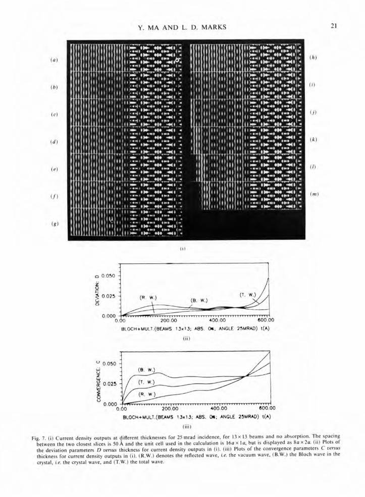
Fig. 7(i) shows the current density output at different thicknesses up to 607.5 A for an incident angle of 25 mrad; absorpt ion is not included. The beam geometry is: the (010) zone is taken as the zero Laue zone; the surface normal is coincident with the z axis; the incident-beam azimuth with respect to the yz plane is zero. The plane of the figure is parallel to the zero Laue zone. The number of beams calculated in the Bloch wave is 13x 13, in reciprocal space ± 2 x ±2 A. Fig. 7(ii) shows plots of the deviat ion parameter D versus thickness, while Fig. 7(iii) shows plots of the convergence parameter C, where (R.W.) denotes the reflected wave, (B.W.) the Bloch wave in the crystal and (T.W.) the total wave. The first slice in Fig. 7(i) is the wave-field output from the Bloch- wave calculat ion which is taken as the reference thick- ness: t = 0. The spacing between the two closest slices is 50 ~,.
For absorption, we appl ied the commonly used phenomenologica l treatment for both the Bloch-wave calculations and the multisl ice calculations. The crys- tal potential in reciprocal space is taken as complex with an imaginary part equal to 10% of the real part. Fig. 8 shows the results for the same condit ions as for Fig. 7, except that an absorption of 10% is included. Compar ing Fig. 8 with Fig. 7, one can easily see that the wave field in the crystal decays sharply for the case with absorption, while it extends deep into the crystal for the case without absorption. However, the reflected wave is not affected seriously
Y. MA A N D L. D. MARKS 21
(a)
(b)
(c)
(d)
(e)
(f)
(g)
(h)
(i)
(j)
(k)
(/)
(m)
(i)
o 0.050
• 0.025 Q
°.°°%. c
(r. w.) /
BLOCH+MULT.(BEAMS 13x~3; ABS. Ore. ANGLE 25MRAD) t(A)
(ii)
o 0.050 (~. w.)
0.025 ~
0.000 1 ................... , ................... , ................... 0 o.O0 200.00 400.00 600. o
BLOCH+MULT.(BE~IdS 13x13; ASS. 0m; ANGLE 25MRAD) t(A)
(iii)
Fig. 7. (i) Current density outputs at different thicknesses for 25 mrad incidence, for 13 x 13 beams and no absorption. The spacing between the two closest slices is 50 ~, and the unit cell used in the calculation is 16a x la, but is displayed as 8a x2a. (ii) Plots of the deviation parameters D versus thickness for current density outputs in (i). (iii) Plots of the convergence parameters C versus
thickness for current density outputs in (i). (R.W.) denotes the reflected wave, i.e. the vacuum wave, (B.W.) the Bloch wave in the crystal, i.e. the crystal wave, and (T.W.) the total wave.

(a)
(b)
(c)
(d)
(e)
( f )
(g)
(i)
22 BLOCH WAVES IN T R A N S M I S S I O N A N D R E F L E C T I O N D I F F R A C T I O N
(h)
(i)
( j)
(k)
(z)
(m)
0.008
o 0.00~ . .
~ 0.004
~ 0.002
0.00%
0.030
u
~ 0.020
~ 0010
0.000
BLOCH+MULT.(OEAMS 13x13: ASS. 10m; ANGLE 25MRAD) t(A)
(ii)
0.00 200.00 400.00 (500.00 BLOCH+MULT.(BEAMS 13•13; AB$. toil; ANGLE 25MRAD) t(A)
(iii)
Fig. 8. (i) Current density outputs at different thicknesses for 25 mrad incidence, for 13 x 13 beams and an absorption of 10%. The spacing between the two closest slices is 50,~, and the unit cell used in the calculation is 16a x la, but is displayed as 8a x2a. (ii) Plots of the deviation parameters D v e r s u s thickness for current density outputs in (i). (iii) Plots of the convergence parameters C v e r s u s thickness for current density outputs in (i).

Y. MA A N D L. D. M A R K S 23
by the absorpt ion as far as the appearance of the images is concerned. The corresponding plots of D and C against slice thickness shown in each figure indicate that including absorpt ion can greatly improve the consistency and convergence as men- t ioned before. This is largely due to the reduction of edge effects. The crossover points in Figs. 7(ii) and (iii) at about 500 ,~, indicate that the edge starts mov- ing into the analyzed area. The edge has more serious effects on the reflected wave than the crystal wave. Fig. 8(ii) shows that the D parameters for the three waves converge to 0.5% after 600 slices, while Fig. 8(iii) shows that the convergence of the C parameter for the crystal wave is a little better than that for the reflected wave, which is main ly due to the difference of the edge effects on two parts. The C parameter can never be zero even if consistency and convergence are achieved, since numerical errors can never be completely el iminated. The reason for the larger scale for C compared to D is that C is a first-order param- eter while D is a second-order parameter. The plots of D and C parameters for the crystal wave quite often start worse and end better, compared to that for the reflected wave. This can be expla ined as fol- lows: methodical errors are more important at the start but later these fall off and numerical errors become important . The former is usually larger than the latter.
IV.2. Effect of the number of beams
When the number of beams calculated in the Bloch wave is changed, both the consistency and conver- gence will be affected. Figs. 9 and 10 show the results for the same condit ions as in Fig. 8, except for a decrease in the number of beams from 13 x 13 to 9 x 9 and 11 x 11, respectively. The images do not look very different from those for 13 x 13 beams. Nevertheless, the D and C parameters clearly indicate the effects of the number of beams, al though these are not very significant. Fig. 9(ii) shows that the D parameters for the reflected wave and the total wave for the 9 x 9 beams case do not converge well, al though that for the crystal wave is not affected significantly, increas- ing from 0.5 to 0.55%. The behavior of the D and C parameters for all three waves for 11 × 11 beams is significantly better than for 9 x 9 beams. The D parameter for the reflected wave for 11 x 11 beams converges to 0"3%, which is 30% smaller than for the 9 x 9 beams. The reduction also occurs in the C parameter. It is interesting that the results for 11 × 11 beams are even a little better than for 13 x 13 beams. This may be expla ined as a consequence of numerical errors in the Bloch-wave calculation which increase with the number of beams, since the number of calcu- lations increases with the square of the number of beams. This also shows that the number of beams in the Bloch-wave calculation required for consistency
and convergence for the reflection case is s imilar to that for the t ransmission case: about 11 x 11.
IV.3. Effect of incidence angle
Figs. 11, 12 and 13 show the results for the same condit ion as in Fig. 8, except that the incidence angles have changed from 25 to 10, 30 and 35 mrad, respec- tively. A noticeable feature of the wave field for small incidence angle (10 mrad) is that it concentrates in the top layer; note also that there is a low electron intensity gap between the top atoms and the vacuum wave for 10 mrad incidence. It should be pointed out that this surface channel ing is not the result of the absorpt ion since the calculat ion with no absorpt ion gives similar results; the wave field is also concen- trated on the top layer. The magnitudes of both D and C parameters of the reflected wave and the total wave for 10 mrad incidence decreased considerably and these curves converge at 600 ~,. However, the magni tudes for both D and C parameters of the crystal wave for 10 mrad increase significantly com- pared to those for 25 mrad. This is possibly due to sharp damping of the crystal wave, which reduces the area available for intensity analysis. The magni- tudes o fbo th the D and C parameters for the reflected wave and total wave for 30 and 35 mrad incidence shown in Figs. 12 and 13 appear not to be affected by the change of incidence angle, al though the D parameters for the reflected wave and total wave for the two incidence angles do not converge so well at 600 ~,. Nevertheless, the magnitudes of the D param- eters of the crystal waves in these two cases increase significantly with the incidence angle and the D parameter of the crystal wave for 35 mrad incidence fails to converge at 600 A and the magni tude of it is larger than 2% at the same thickness. It appears that the larger the incidence angle is the worse the con- sistency and convergence are. There are two reasons for this. First, in the multislice calculation, the approximat ion is generally made that the phase grat- ing does not vary with small changes of the incidence angle and all effects of the changes of incidence angle are included in the propagator. This error mainly affects the consistency and convergence of the crystal wave. Second, when the incidence angle increases, the interaction between the electron wave in the vacuum and the surface potential becomes more important; this mainly affects the consistency and convergence of the reflected wave and will be dis- cussed later.
IV.4. Effect of surface potential
If one studies the wave field in vacuum in Figs. 7, 8 and 9 a little more closely, one can observe a slight difference between the vacuum wave (i.e. reflected wave) in the first slice and that in the consequent

24 BLOCH WAVES IN TRANSMISSION AND REFLECTION DIFFRACTION
(a)
(b)
(c)
(d)
(e)
( f )
(g)
(h)
(i)
(j)
(k)
(z)
(m)
(i)
0.008
o 0.00~
g 0.004
~ 0 002
0 00%
(e. w.)
BtOCl-++~utr. (B~AMS 9.9; ABS. 10m; ANGLE 25MRAD) t(A)
(ii)
0.030
(r. W.) ~ - ~ ~ o.o,o o ~ ~
/ I (R. w) u
0.000 I ................... , .................. , ................... ,
0.00 200.00 400.00 600.00
Bt.OCH-+MUIT. (rP_.AMS 9X9; ABS. 10q; ANGLE. 25MRAO) t(A)
(iii)
Fig. 9. Corresponding results under the same conditions as for Fig. 8, except that the number of beams in the Bloch-wave calculation is 9x9.

Y. MA A N D L. D. M A R K S 25
(a)
(b)
( c )
(d)
(e)
( f )
(g)
(h)
(i)
(j)
(k)
(t)
(m)
0.008
o 0.006
~ 0.004 ~ 0.002
0.000
(B. w.)
/~~___~ ( . ~) i iv, iv, *vvlvv vlvv iv|iv, v v T V v v v v , , I v v v v y l Ivl I I I I I V V V V T I V V l I ,
0.00 200.00 400.00 600.00
BLOCH+MULT.(BEAMS 11x11. ABS. 10w; ANGLE 25MRAD) t(A)
(ii)
0.030
6J 0.020 o z w
i oo,o (~- w. 2 ~ - - - ~ w . )
oooo ~6 ................... " .................. ' ....................
• 200.00 400.00 600.00
BLOCH+MULT.(BEAMS 11wl1: ABS. lore; ANGLE 25MRAD) t(A)
(iii)
Fig. 10. Corresponding results under the same conditions as for Fig. 8, except that the number of beams in the Bloch-wave calculation is l l x l l .

26 BLOCH WAVES IN TRANSMISSION AND REFLECTION DIFFRACTION
(a)
(b)
(c)
(d)
(e)
(/)
(g)
(h)
(i)
( j )
(k)
(0
(m)
(i)
0.024 t ~ 0.016
0.00% :[/ (~ w.) - ( . . w.) - 200.00 400.00 (500.00
BLOCH+MULT.(BEAMS 13x13; ABS. 101: ANGLE 10MRAD) t(A)
(ii)
0.060
~J 0.040 Y
0.020
(e. w.)
(r. w.) ~ -
o ~ (R. w.) - - - - - - - - - - " 0.000 .............. ~-~-~ .... ,, ............ , .... .~ ..............
0.00 200.00 400.00 600.00
8LOCH+MULT.(BEAMS 13x13; ABS. lOl; ANGLE IOMRAD) t(A)
(iii)
Fig. ] ]. Corresponding results under the same conditions iis for Fig. 8, except that the incidence angle is 10 mrad.

Y. MA A N D L. D. M A R K S 27
(a)
(b)
(c)
(a)
(e)
(f)
(g)
(h)
(i)
(j)
(k)
(l)
(m)
(i)
0.015
0.012 173
0009 o ~ 0.006
o 0003
0.000
(e. w.)
/ .._-.----
- - ~ - ~ - (R. w.)
r,r,,,,l,,, ,, ,i,,,, i I,,,,,,,,,T,,,, ,,,fill,,,,,,, ,,,,,,,,,, I
0.00 200.00 400.00 600.00
BIOCH~-MUL].(BEAMS 13x13; ABS. lore; ANGLE 30MI~AD) t(A)
(ii)
0.050
6J° 0.040 ~
o 0.030 " " Z klJ
0.020 UJ
0.010
0.000 0.00 200.00 400.00 800.00
BLOCH÷MULT.(BEAMS 13x13; ABS. 1011; ANGLE 30MRAD) t(A)
(i i i)
Fig. 12. Corresponding results under the same conditions as for Fig. 8, except that the incidence angle is 30 mrad.

28 B L O C H WAVES IN T R A N S M I S S I O N A N D R E F L E C T I O N D I F F R A C T I O N
(a)
(b)
(c)
(d)
(e)
(f)
(g)
D IP ,o -
,:.,. 1. ; ; . , ' - - . . . . ' ~ . : " . , ~ ~ b li=,=m ° ,~, " . . . = , . _ . ~..;. --... .
~. -. . . .
o. :- ;3 ..... , , i ~ . .
. o . ~ ~.~..., . ;L'-- -" : - . o ; ; ; . " : . . . . . :.;..- .,-. .
~ and =, °
;:,.-.. ",..-"... :o=,~ ~f,,o" ."
)) . : .
;- ) : - : 14 - : •
• o l i n , a0 , o ~. -
°t,,~
(h)
(i)
(j)
(k)
(/)
(m)
(i)
0 . 0 2 0
r.,, 0.018
i 0.012 0.008
0.004
0.000 0
(B. w.)
(r . w.) - - - - - - - - ~ R . - T - - - - - - W.)
. . . . . . . . . . . . . . . . ~6b'.6b . . . . . . . . . . . . . . . . . . . . . . . . . . . . . . . . . . . . . ' ~0 400.00 800.00 BLOCFt+MUL_T.(BEAMS 13w13; ABS. 10t; ANGLE 35MRAD) t(A)
(ii)
0.050
o 0.040
~ 0.030
~ 0.020 W
~ 0.010
0.000 O,
i , , T , , , , , v v T T v v v , v v T T , , I , , , , , , , , , , , , 1 , , T T , , I T T , , V T , V V , V , V V V !
200.00 400.00 800.00
BLOCH+MULTo(BL~0~S ~3x~3; ASS. 1Oa; ANGLE 35MRAD) t(A)
(iii)
Fig. 13. Corresponding results under the same conditions as for Fig. 8, except that the incidence angle is 35 mrad.

Y. MA A N D L. D. M A R K S 29
slices. The analysis of both D and C parameters of the vacuum waves has already shown the deviat ion of the solutions in the multisl ice s imulat ion from the Bloch-wave solutions. The major part of the deviat ion is due to the artificial surface truncation in the Bloch- wave calculation. However, the effects of the surface truncation in the Bloch-wave calculation is much smaller than we expected, which is consistent with the results of Howie (1988), but contrary to the con- clusion by Britze & Meyer-Ehmsen (1978). This merits further studies.
The arguments given at the beginning of this section analyt ical ly proved that the multislice iter- ation in our case is actually equivalent to the Picard iteration for numerical ly solving the true solution of the SchrOdinger equation in integral form. This means that the iteration must converge to the true wave field in the potential without surface truncation in the reflection case since the surface potential is automati- cally included in the phase grating in multisl ice calcu- lations. The small effect of the surface truncation in the Bloch-wave calculation results in a much faster converging speed in multislice calculation, which leaves more room for the s imulat ion of surface features.
As ment ioned before, the first slice (t = 0) is the Bloch-wave solution which plays two roles here: (1) the incidence wave field in muitislice iteration; (2) the initial wave field in the Picard iteration. It is obvious that the deviation should first emerge in the area close to the surface and then become stable and gradually spread out with increasing thickness, since the surface potential decays exponent ia l ly with increase of the distance from the surface. In other words, the convergence regarding the effects of sur- face potential (since the accumulat ion of numerical errors during the muitisl ice iteration is unavoidable the convergence cannot be considered as exclusively perfect) should also first emerge in the area close to the surface. To demonstrate this more clearly, the square of the differences between the two nearest slices, F,.,,_ i(q) = [0(q, Y,,) - 0(q, y,_,)]2 were studied by projecting F,. ,_,(q) onto the z axis. In the co- ordinate system we use here, the incidence vector is along the y axis and the z axis points into the crystal surface. The projected intensities of F,,.,,-i(q) against z for 25 and 30 mrad incidence are shown in Figs. 14 and 15 respectively. A peak occurs just at the surface in the first curve of F , .n ,(q) in each case, as the initial wave is scattered by the surface potential. The peak
J• i ,,
. _ ~ A _../k_
Fig. 14. Plots of the projected intensity of F, . ._ t (q) versus thickness. Each curve is calculated from the two closest slices in Fig. 8, and the incidence angle is 25 mrad.

30 BLOCH WAVES IN T R A N S M I S S I O N AND R E F L E C T I O N D I F F R A C T I O N
gradually moves out and the range with a flat and low intensity gradually increases with the iteration n or slice number m. This becomes clear for r n > 5 (n > 250), i.e. after the fifth curve in Fig. 15. The multiple peaks in the curves of F, , ,_~(q ) with 5 < m < 11 are probably due to either oscillatory convergence of the Picard series, similar to the convergence of the Fourier series, or the accumulation of numerical error. They finally decay to a series of small modulations. One important feature in Figs. 14 and 15 is that the convergence of the Bloch wave in the crystal is well preserved.
The present results show that the effects due to the surface potential on the vacuum wave are not incidence-angle related. The magnitudes of both D and C parameters of the vacuum waves in Figs. 8, 11, 12 and 13 do not show any clear trend with increasing incidence angle. This appears to be contrary to what one might expect; the surface-poten- tial effects should become more serious for larger incidence angle because of the stronger interaction between the larger components normal to the surface of the electron wave and the surface potential. This
is worth further study both experimentally and theoretically.
V. Comparison with the solution in multislice only
When the program is shifted to the reflection-multi- slice-only mode, we obtain the results shown in Figs. 16(i), (ii) where (i) is the result without absorption and (ii) is the result with an absorption of 10%. Here we are following Peng & Cowley's (1986, 1988) treat- ment: a plane wave smoothed by a Gaussian function tilted towards the crystal surface is introduced into the left part of the unit cell in the vacuum. The tilt angle is 25 mrad. Both the wave reflected from the crystal and the wave penetrating into the crystal in (d), (e) and (f) at the areas which are close to the crystal surface have some correlation with the true stationary solution in Fig. 7, although the deviation is still obvious. Owing to the edge effects, it appears, however, that the solution is unstable. If absorption is introduced [Fig. 16(ii)], the result is not much better.
. . . . . . l m t L ~1~._ ~ . - ~ ~ -
Fig. 15. Plots of the projected intensity of F,,,_~(q) versus thickness. Each curve is calculated from the two closest slices in Fig. 12, and the incidence angle is 30 mrad.

Y. MA AND L. D. MARKS 31
VI. Discussion
We have been able to demonstrate here that the Bloch-wave method is close to a genuine solution of the dynamical reflection problem, and even though
there may be some errors due to the effect of neglect- ing a surface potential, these can be eliminated by using the multislice as a Picard iteration. This feature is especially important since it opens up a whole range of different ways of calculating reflection problems.
(a)
(b)
(c)
(d)
(e)
(f)
(g)
(h)
(i)
(j)
0 % ; 25 m r a d (il
1 0 % ; 2 5 m r a d (ii)
Fig. 16. Current density outputs at different thicknesses for 25 mrad incidence in the mulfislice-only mode, with (i) no absorption and (ii) 10% absorption. The thicknesses from (a) to ( j) are: 0, 20.2, 40.5, 81-0, ]62.0, 202.5, 243-0, 283.5, 324.0, 405.0 A.

32 BLOCH WAVES IN T R A N S M I S S I O N A N D R E F L E C T I O N D I F F R A C T I O N
As ment ioned above, the Picard solution is uncondi- t ionally convergent, and we can expect that the speed with which it converges will depend upon how near the first wave function is to the true solution. The results of intensity analysis clearly indicate that the Bloch-wave solution is quite close to t' ~ true solution, and the effects of surface truncation in the Bloch-wave calculation are unexpectedly small. Tberefore, we can envisage solving problems involving surface relaxa- tions by using a solution generated from a Bloch-wave approach and then mult isl icing it to convergence. Since the multisl ice is a fast approach, and even faster if one utilizes array processors, this may be an efficient method of solving many otherwise intractable problems.
One obvious problem is edge effects; multisl ice is not a true numerical solution since its periodic con- t inuation leads to edge effects. One can overcome these problems to some extent by using very long unit cells as we have done. A more robust and general approach is possibly to use patching or some other technique to avoid the edge effects. For instance, one possibility would be at each slice to force the edge of the cell, or a region near the edge, to have the same ampl i tude and phase. This is an area for further numerical research.
One addi t ional point that appears to be quite clear is that using an incident top-hat wave function does not seem to be a reliable approach. Without the addit ional informat ion from the Bloch-wave solution, we cannot see how one can readily identify when the solution is not stationary. It is possible that one could stabilize this approach, avoiding the edge effects, and then use the multislice alone to sum the Picard series. If this is possible, then this might be a s imple method of solving the general reflection diffraction problem in a relatively simple conceptual manner.
A final point should be mentioned, which is both a proof and a caret. In our original version of these programs there was a numerical error in the Bloch- wave to multisl ice conversion. Even with this error, multisl icing still produced convergent results, albeit
a little slower than in the results presented herein. Clearly, the combined approach is quite robust.
This work was supported by the National Science Foundat ion through Northwestern University Materials Research Center, Grant No. 85-20280.
References
BETHE, H. (1928). Ann. Phys. (Leipzig), 87, 55-129. BRITZE, K. & MEYER-EHMSEN, G. (1978). Surf. Sci. 77, 131-141. COLELLA, R. (1972). Acta Cryst. A28, 11-15. COWLEY, J. M. & MOODIE, A. F. (1957). Acta Cryst. 10, 609-619. COWLEY, J. M. & N1ELSEN, H. (1975). Ultramicroscopy, I,
145-150. EWALD, P. P. (1917). Ann. Phys. (Leipzig), 54, 519-556. FUJIMOTO, F. (1959). J. Phys. Soc. Jpn, 14, 1558-1568. GASKILL, J. D. (1978). Linear System Fourier Transforms and
Optics, p. 363. New York: John Wiley. HARRIS, J. J., JOYCE, B. A. & DOBSON, P. J. (1981a). SurJl Sc'l.
103, L90-L96. HARRIS, J. J., JOYCE, B. A. & DOBSON, P. J. (1981b). Surf. Sci.
108, L444- L446. HOWlE, A. (1988). Personal communication. Hsu, T. (1983). Ultramicroscopy, 11, 167-172. Hsu, T. & COWLEY, J. M. (1983). Ultramicroscopy, I I, 239-250. ICHIM1YA, A. (1983). J. Appl. Phys. Jpn, 22, 176-180. ISHIZUKA, K. & UYEDA, N. (1977). Acta Cryst. A33, 740-749. KATO, N. (1952), J. Phys. Soc. Jpn, 7, 397-414. KOHRA, K., MOKIERE, K., NAKANO, S. & ARIYAMA, M. (1962).
J. Phys. Soc. Jpn, 17, B-II, 82-91. MA, Y. & MARKS, L. D. (1989). Acta Cryst. A45, 174-182. MAKSYM, P. A. & BEEBY, J. L. (1981). Surf. Sci. II0, 423-438. MAKSYM, P. A. & BEEBY, J. L. (1982). Appl. Surf. Sci. 11/12,
663-676. MARKS, L. D. & MA, Y. (1988). Acta Cryst. A44, 392-393. MIYAKE, S., KOHRA, K. & TAKAGi, M. (1954). Acta Cryst. 7,
393-401. MOON, A. R. (1972). Z. Naturforsch. Tell A, 27, 390-395. OSAKABE, H., TANISHIRO, Y., YAGI, K. & HONJO, G. (1981).
Surf. Sci. 102, 424-442. PENt:;, P. M. & COWLEY, J. M. (1986). Acta Cryst. A42, 545-552. PENG, P. M. & COWLEY, J. M. (1988). Acta Cryst. A44, 1-5. SELF, P. G., O'KEEFE, M. A., BUSECK, P. R. & SPAR(50, A. E. C.
(1983). Ultramicroscopy, II , 35-52. SHUMAN, H. (1977). UItramicroscopy, 2, 361. WHELAN, M. J. & HIRSCH, P. B. (1957). Philos. Mag. 2, 1121-1142,
1303-1324. WOOD, C. E. C. (1981). Surf. Sci. 108, L441-L443.