iwaa2010 - r. beunard – september 13-17, 2010 – desy, hamburg, germany 1 20m rémy beunard a....
Post on 19-Dec-2015
212 views
TRANSCRIPT

IWAA2010 - R. BEUNARD – September 13-17, 2010 – DESY, Hamburg, Germany 1
20m
The Initial Geodetic Survey for the SPIRAL2 Process Installation at GANIL
Rémy Beunard A. Lefevre, F. Legruel
GANIL, CAEN, FRANCE
The 11th INTERNATIONAL WORKSHOP ON ACCELERATOR ALIGNMENT DESY, Germany, September 13-17, 2010

IWAA2010 - R. BEUNARD – September 13-17, 2010 – DESY, Hamburg, Germany 2
Outline
Overview about SPIRAL2 project
The Geodetic Systems
Process installation principle
Monitoring of Building Movements
Summary
IWAA2010 - R. BEUNARD – September 13-17, 2010 – DESY, Hamburg, Germany 3
PARIS
CAEN
FRANCE
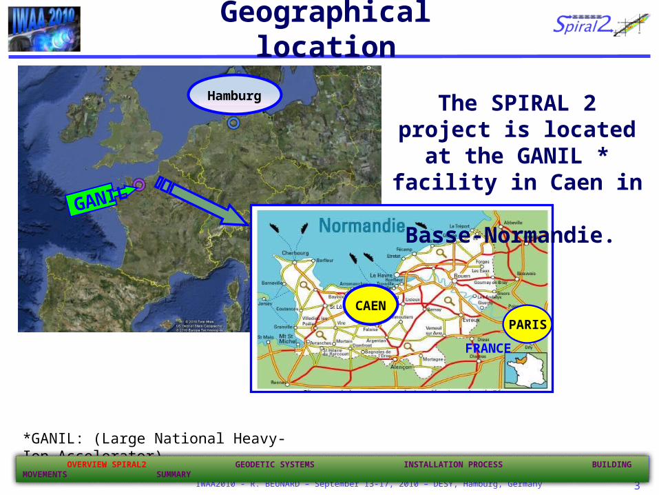
Geographical location
The SPIRAL 2 project is located at the GANIL *
facility in Caen in Basse-Normandie.
*GANIL: (Large National Heavy-Ion Accelerator)
GANIL
OVERVIEW SPIRAL2 GEODETIC SYSTEMS INSTALLATION PROCESS BUILDING MOVEMENTS SUMMARY
Hamburg
IWAA2010 - R. BEUNARD – September 13-17, 2010 – DESY, Hamburg, Germany 4
HRS+RFQ Cooler
HRS+RFQ Cooler
GANIL/SPIRAL1/SPIRAL2 facilityGANIL/SPIRAL1/SPIRAL2 facility
A/q=6 Injector option
A/q=6 Injector option
DESIR Facility low energy RIB
DESIR Facility low energy RIB
RIB Production CaveUp to 1014 fiss./sec.
RIB Production CaveUp to 1014 fiss./sec.
A/q=3 HI sourceUp to 1mA
A/q=3 HI sourceUp to 1mA
A/q=2 sourcep, d, 3,4He 5mA
A/q=2 sourcep, d, 3,4He 5mA
LINAC: 33MeV p, 40 MeV d, 14.5 A MeV HI
LINAC: 33MeV p, 40 MeV d, 14.5 A MeV HI
S3 separator spectrometer
S3 separator spectrometer
Neutrons For Science
Neutrons For Science
GANIL/SPIRAL 1 today
CIME cyclotron RIB at 1-20 AMeV
(up to 9 AMeV for fiss. fragments)
CIME cyclotron RIB at 1-20 AMeV
(up to 9 AMeV for fiss. fragments)
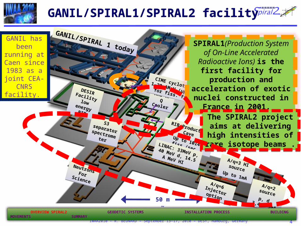
SPIRAL1(Production System of On-Line Accelerated Radioactive Ions) is the first facility for production and
acceleration of exotic nuclei constructed in France in 2001.
50 m ~
GANIL has been running at Caen since 1983 as a joint CEA-CNRS
facility.
The SPIRAL2 project aims at delivering high intensities of
rare isotope beams .
The SPIRAL2 project aims at delivering high intensities of
rare isotope beams .
OVERVIEW SPIRAL2 GEODETIC SYSTEMS INSTALLATION PROCESS BUILDING MOVEMENTS SUMMARY
IWAA2010 - R. BEUNARD – September 13-17, 2010 – DESY, Hamburg, Germany 5
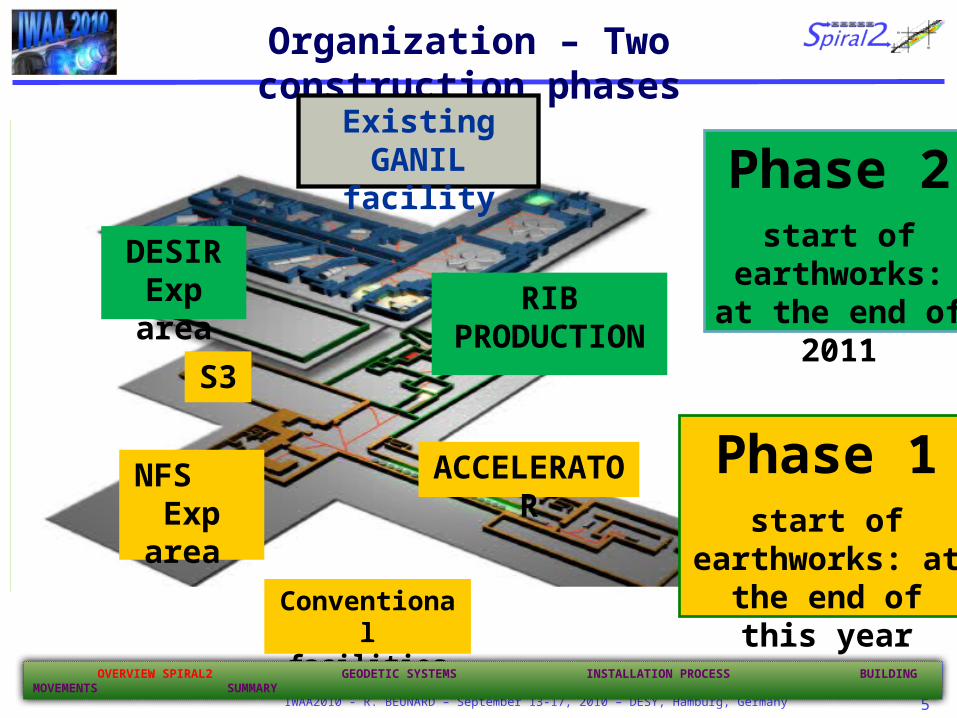
Organization – Two construction phases
Existing GANIL facility
DESIRExp area
Phase 2start of earthworks: at the end of 2011
RIB PRODUCTION
NFS Exp area
ACCELERATOR
Conventional facilities
Phase 1start of earthworks:
at the end of this year
S3
OVERVIEW SPIRAL2 GEODETIC SYSTEMS INSTALLATION PROCESS BUILDING MOVEMENTS SUMMARY

IWAA2010 - R. BEUNARD – September 13-17, 2010 – DESY, Hamburg, Germany 6
GANIL
Phase 1Accelerator & S3,
NFS
Building 3D visualization
DESIR
Phase 2RIB
PRODUCTION
conventional facilities(electricity, water
cooling, ventilation, climatization, handling systems,……)
Process will be installed underground at level -9.50 m
OVERVIEW SPIRAL2 GEODETIC SYSTEMS INSTALLATION PROCESS BUILDING MOVEMENTS SUMMARY

IWAA2010 - R. BEUNARD – September 13-17, 2010 – DESY, Hamburg, Germany 7
Process Phase 1Cross section
25 m ~
Accelerator Process : level -9.50 m
Towards Production
Building
3D design with SolidWorks
OVERVIEW SPIRAL2 GEODETIC SYSTEMS INSTALLATION PROCESS BUILDING MOVEMENTS SUMMARY

IWAA2010 - R. BEUNARD – September 13-17, 2010 – DESY, Hamburg, Germany 8
HRS + RFQ Cooler
RIB Production
RIB to GANIL
Level : -1.75 m
RIB to DESIR
Production
Module
Beam from the accelerator
Level : -8.0 m
Building is designed to comply with all the safety constraints imposed by the high radiation activity,
Studies on the alignment are in progress
Process Phase 2
OVERVIEW SPIRAL2 GEODETIC SYSTEMS INSTALLATION PROCESS BUILDING MOVEMENTS SUMMARY

IWAA2010 - R. BEUNARD – September 13-17, 2010 – DESY, Hamburg, Germany 9
SPIRAL2 …the milestones
2007 2008 2009 2010 2011 2012 2013 2014 2015 2016
Construction of new detectors
Exp. with S3 Exp. with S3
Exp. with NFS
Construction
Phase 1 Stable ion beams from LINACCo
mm
is-
sio
nin
g
Ph
ase
1 Construction
Phase 2 Com
mis
-si
onin
g
Phas
e 2
First LINAC
Beam
Feb. 2012
TodayToday First RIB
Oct. 2013
RIB
Geodetic Measurement
Installation and Alignment process
OVERVIEW SPIRAL2 GEODETIC SYSTEMS INSTALLATION PROCESS BUILDING MOVEMENTS SUMMARY
IWAA2010 - R. BEUNARD – September 13-17, 2010 – DESY, Hamburg, Germany 10
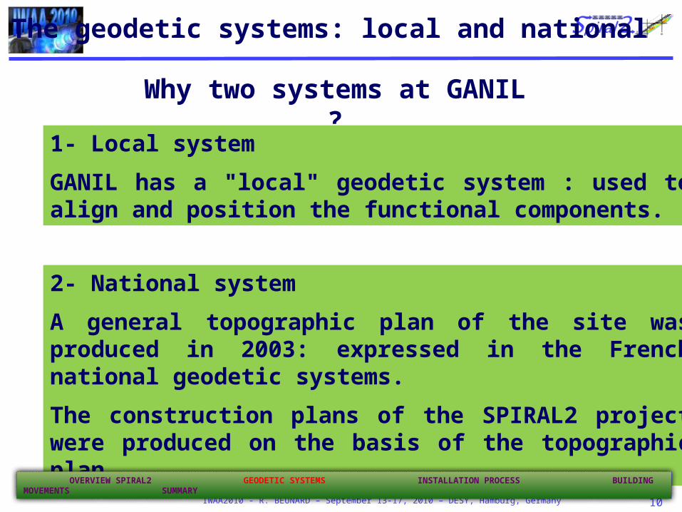
The geodetic systems: local and national
Why two systems at GANIL ?
1- Local system
GANIL has a "local" geodetic system : used to align and position the functional components.
2- National system
A general topographic plan of the site was produced in 2003: expressed in the French national geodetic systems.
The construction plans of the SPIRAL2 project were produced on the basis of the topographic plan.
OVERVIEW SPIRAL2 GEODETIC SYSTEMS INSTALLATION PROCESS BUILDING MOVEMENTS SUMMARY

IWAA2010 - R. BEUNARD – September 13-17, 2010 – DESY, Hamburg, Germany 11
the facility.
CSS1
X = 500. 00 m
Y = 200.000 m
Z = 20.000 m
Y
XZ
25 m
CIME
The local geodetic system
CSS1
X = 100. 000 m
X = 500. 00 m
Y = 200.000 m
Z = 10. 000 m Z= 20.000 m
CSS2
X = 100. 000 m
X = 500. 000 m
Y = 229.0154 m
Z = 10. 000 m
Z = 20.000 m
« Point Croix »
X = 111. 000 m
X = 511.000 m
Y = 241.5154 m
Z = 10. 000 m
Z = 20.000 m
connection of the radioactive beam
transport line
Reference network marks
The characteristics :
Cartesian coordinate system defined by the centres of the two cyclotrons, CSS1 and CSS2. Estimated absolute
precision ±2.0 mm
OVERVIEW SPIRAL2 GEODETIC SYSTEMS INSTALLATION PROCESS BUILDING MOVEMENTS SUMMARY
IWAA2010 - R. BEUNARD – September 13-17, 2010 – DESY, Hamburg, Germany 12
Y
X
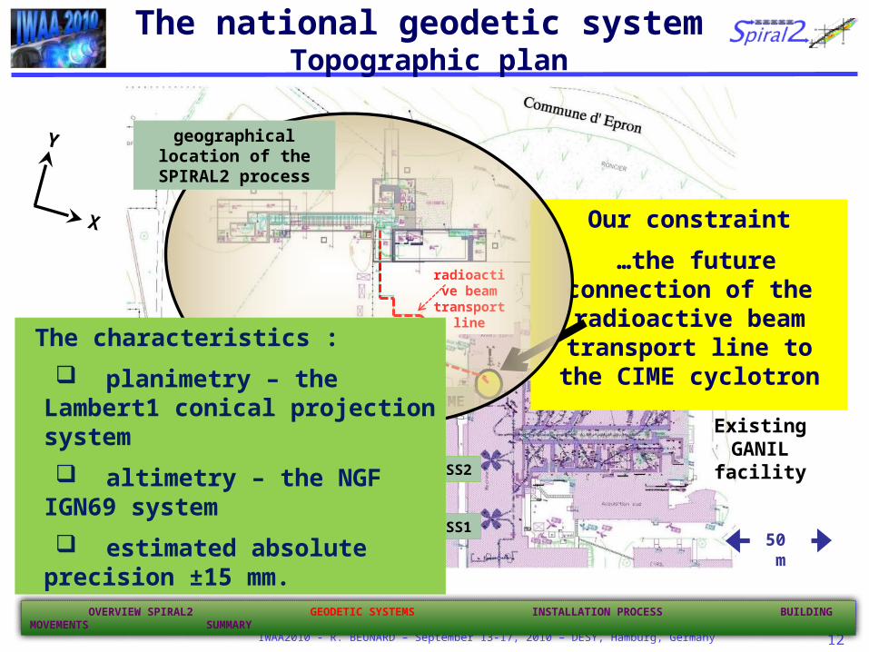
The national geodetic system Topographic plan
CSS2
CSS1
CIME
radioactive beam
transport line
Existing GANIL facility
Our constraint
…the future connection of the radioactive beam transport line
to the CIME cyclotron
geographical location of the SPIRAL2 process
The characteristics :
planimetry – the Lambert1 conical projection system
altimetry – the NGF IGN69 system
estimated absolute precision ±15 mm. 50 m
OVERVIEW SPIRAL2 GEODETIC SYSTEMS INSTALLATION PROCESS BUILDING MOVEMENTS SUMMARY

IWAA2010 - R. BEUNARD – September 13-17, 2010 – DESY, Hamburg, Germany 13
S118
S1191
S123S122
7031
7032
7033
7034
25 m
Topographic ground point (station)
New ground point outside existing installations
… Connection of the local geodetic system to the national systemN
ow, t
he p
roje
ct c
oord
inat
es
can
be e
xpre
ssed
in b
oth
geod
etic
sys
tem
s XZ
Y
Local system
XZ
YLambert 1 system
Connection consisted :
to transfer 4 points (in blue) to the outside of the installations.
on the topographic plan, 4 stations (in red) known in the national system were selected .
A change of system : Helmert transformationThis operation had 2 objectives:
"register" precisely both construction and building plans to match our local system,
simplify the installation of the process to guarantee the required connection.
Phase 2 radioactive
beam transport line
OVERVIEW SPIRAL2 GEODETIC SYSTEMS INSTALLATION PROCESS BUILDING MOVEMENTS SUMMARY
IWAA2010 - R. BEUNARD – September 13-17, 2010 – DESY, Hamburg, Germany 14
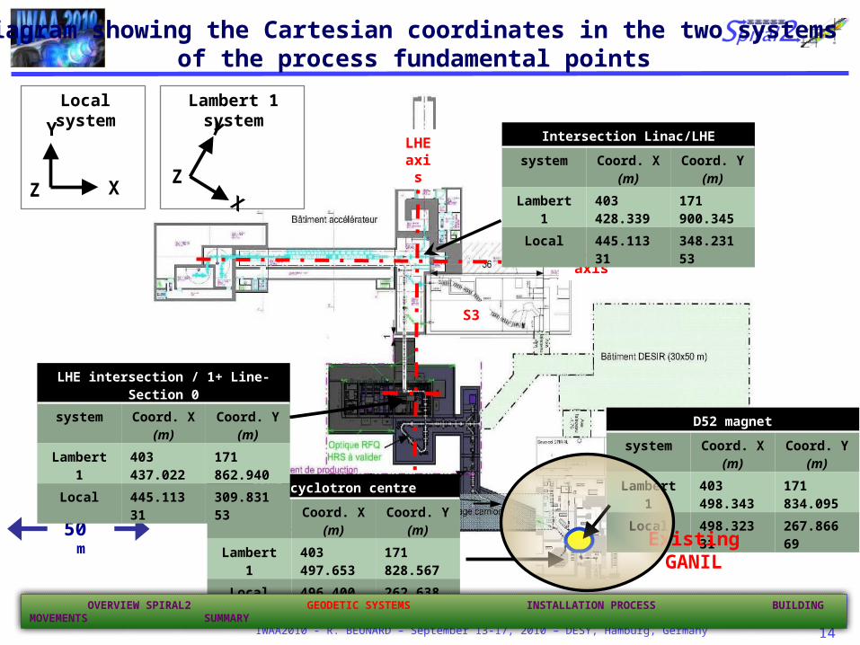
Diagram showing the Cartesian coordinates in the two systems of the process fundamental points
Linac/LHE intersectionsystem X (m) Y (m)
Lambert 1 403 428.339 171 900.345Local 445.113 31 348.231 53
Linac axis
LHE axis
50 m
XZ
Y
Local system
XZ
YLambert 1 system
Intersection Linac/LHE
system Coord. X (m) Coord. Y (m)
Lambert 1 403 428.339 171 900.345
Local 445.113 31 348.231 53
D52 magnet
system Coord. X (m) Coord. Y (m)
Lambert 1 403 498.343 171 834.095
Local 498.323 31 267.866 69CIME cyclotron centre
system Coord. X (m) Coord. Y (m)
Lambert 1 403 497.653 171 828.567
Local 496.400 01 262.638 39
LHE intersection / 1+ Line-Section 0
system Coord. X (m) Coord. Y (m)
Lambert 1 403 437.022 171 862.940
Local 445.113 31 309.831 53
S3
Existing GANIL
OVERVIEW SPIRAL2 GEODETIC SYSTEMS INSTALLATION PROCESS BUILDING MOVEMENTS SUMMARY

IWAA2010 - R. BEUNARD – September 13-17, 2010 – DESY, Hamburg, Germany 15
Surface geodetic network project
Type of geodetic pillar equipped with a forced centring
1
Pillar of the Linac and LHE line axes (included in the geodetic network)
Geodetic network pillar
6
7
8
2
9
5
4
3
10
Phase 2 radioactive
beam transport line
This geodetic network had two objectives:
to provide reference points to allow installation of the process at level -9.50 m,
to monitor movements of the building at level 0.
Pillar will be anchored on at the geologically highly stable bed and isolated from the future
infrastructures and their excavations.
These pillars will remain in position throughout the lifetime of the accelerator
How to install the process geographically ?
OVERVIEW SPIRAL2 GEODETIC SYSTEMS INSTALLATION PROCESS BUILDING MOVEMENTS SUMMARY

IWAA2010 - R. BEUNARD – September 13-17, 2010 – DESY, Hamburg, Germany 16
1
3
4
2
Surface geodetic network project
Reference pillar for process installation at – 9.50 m
Phase 2 radioactive beam
transport line
Network takes into account the land occupied by the worksite, earthworks area and final layout
Pillars must be installed after the earthworks and before starting the civil engineering work for the building
Surveying for surface network will be carried out by TDA tacheometer with GPS observations
Simulation remains to be done
Final accuracy expected : ± 3.0 mm ?
OVERVIEW SPIRAL2 GEODETIC SYSTEMS INSTALLATION PROCESS BUILDING MOVEMENTS SUMMARY

IWAA2010 - R. BEUNARD – September 13-17, 2010 – DESY, Hamburg, Germany 17
The first solution which occurred to us is to transfer the beam Linac axis by optical plummet through this survey shaft.
Installation the 2nd order geodetic network
Linac axis
Pillar N°1
Pillar N°2
shaft shaft
longitudinal section of the Linac
Lev. 0.0 m
Lev. -9.50 m
Filling up layer(calcareous stone extracted
during the excavation)
This solution was rejected because of the risk of neutron scattering at level 0 due to
the difficulty to press down the calcareous stone around the shaft
Transfer of aboveground coordinates into the tunnel via plumbing
OVERVIEW SPIRAL2 GEODETIC SYSTEMS INSTALLATION PROCESS BUILDING MOVEMENTS SUMMARY
The beam line axis will be
transferred onto the concrete
slab from pillars 1 to 2

IWAA2010 - R. BEUNARD – September 13-17, 2010 – DESY, Hamburg, Germany 18
talus
talus
Sketch
Block limit
ACC 1/2-2/2
Intersection
Linac / LHE
Pillar N° 1 Lev. + 1.43 m
Lev. 0.0 m
Slope
Slab
Lev -9.50 m
Slope
Lines of sight
Lines of sight
Markers sealed in the slab
Installation principle of the process (Linac)
axes at level – 9.50 m
Installation the 2nd order geodetic network
Pillar N° 2 Lev. + 1.43 m
Linac axis
Constraint of this solution :
This operation must be performed before the concrete slabs of the higher levels are poured (ceiling of Linac and beam transport rooms)
reference marks will be sealed in the slab at predefined positions,
their Cartesian coordinates will be determined using the geodetic pillars of the first order network.
OVERVIEW SPIRAL2 GEODETIC SYSTEMS INSTALLATION PROCESS BUILDING MOVEMENTS SUMMARY

IWAA2010 - R. BEUNARD – September 13-17, 2010 – DESY, Hamburg, Germany 19
Installation the 2nd order geodetic network
Partial view of the topometric network of the
process at -9.50mInstallation of a floor grid reference
spaced between 3 and 5 m.
OVERVIEW SPIRAL2 GEODETIC SYSTEMS INSTALLATION PROCESS BUILDING MOVEMENTS SUMMARY
Network measurements with TDA 5005 coupled with Laser Tracker LTD 500 and digital Level Leica NA3003
Standard deviation of a point expected 0.1 mm
Reference marks sealed in the slab
Reference marks sealed againts the walls
(study is ongoing)
Viewing window installed during the making of concrete walls
IWAA2010 - R. BEUNARD – September 13-17, 2010 – DESY, Hamburg, Germany 20
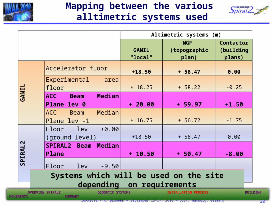
Altimetric systems (m)
GANIL "local"NGF
(topographic plan)Contactor
(building plans)
GANIL
Accelerator floor +18.50 + 58.47 0.00
Experimental area floor + 18.25 + 58.22 -0.25
ACC Beam Median Plane lev 0 + 20.00 + 59.97 +1.50
ACC Beam Median Plane lev -1 + 16.75 + 56.72 -1.75
SPIRAL2
Floor lev +0.00 (ground level) +18.50 + 58.47 0.00
SPIRAL2 Beam Median Plane + 10.50 + 50.47 -8.00
Floor lev -9.50 (Linac) + 9.00 + 48.97 -9.50
Mapping between the various alltimetric systems used
Systems which will be used on the site depending on requirements
OVERVIEW SPIRAL2 GEODETIC SYSTEMS INSTALLATION PROCESS BUILDING MOVEMENTS SUMMARY
IWAA2010 - R. BEUNARD – September 13-17, 2010 – DESY, Hamburg, Germany 21
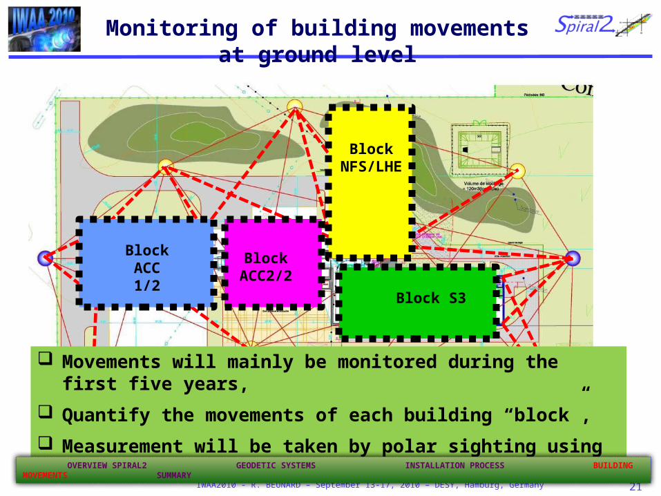
Monitoring of building movements at ground level
Lines of sight to monitor the building
Block ACC 1/2
Block ACC2/2
Block S3
Block NFS/LHE
Movements will mainly be monitored during the first five years,
Quantify the movements of each building “block”,
Measurement will be taken by polar sighting using tacheometers from pillars.
OVERVIEW SPIRAL2 GEODETIC SYSTEMS INSTALLATION PROCESS BUILDING MOVEMENTS SUMMARY

IWAA2010 - R. BEUNARD – September 13-17, 2010 – DESY, Hamburg, Germany 22
Summary
Final goal : to guarantee the future connection of the new accelerator,
The connection requires designing a “surface” network linked to the local survey,
The local system was “connected” to the national system : to express in both systems the process and construction plans requirements,
The first order network geodetic pillars will be surveyed by tacheometer TDA 5005 coupled to a differential GPS,
The surface network will be transferred to the floor accelerator tunnel, in order to define the reference network for aligning all functional components.
See poster: « Survey and Alignment Concept for the SPIRAL2 Accelerator »
OVERVIEW SPIRAL2 GEODETIC SYSTEMS INSTALLATION PROCESS BUILDING MOVEMENTS SUMMARY

IWAA2010 - R. BEUNARD – September 13-17, 2010 – DESY, Hamburg, Germany 23
Thanks for your attention!