ivory 2 series - music marketing · user manual tla udio ® ivory 2 series 5050 mono valve preamp...
TRANSCRIPT
user manual
TLAudio
®
Ivory 2 Series
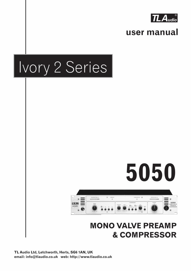
5050
MONO VALVE PREAMP& COMPRESSOR
TL Audio Ltd, Letchworth, Herts, SG6 1AN, UKemail: [email protected] web: http://www.tlaudio.co.uk
CONTENTS 1 INTRODUCTION 2 PRECAUTIONS 3 INSTALLATION 3.1 A.C. Mains Supply 3.2 Audio Operating Level 3.3 Microphone Input 3.4 Line Input 3.5 Instrument Input 3.6 Output 3.7 Mounting 3.8 Rear Panel 4 OPERATION 4.1 Front Panel 4.2 Input Selection 4.3 30dB Pad 4.4 Phantom Power 4.5 Microphone Input 4.6 Line Input 4.7 Instrument Input 4.8 High Pass Filter 4.9 What is Compression? 4.10 Why Valve Compression 4.11 Overview of Compressor Operation 4.12 Threshold 4.13 Ratio 4.14 Attack & Release 4.15 Knee 4.16 Gain Make Up 4.17 Compressor On 4.18 Output Level 4.19 Bar Graph Meters 4.20 Optional DO-2 Digital Output Card 5 GETTING STARTED 5.1 Connections 5.2 In Use 6 SPECIFICATIONS
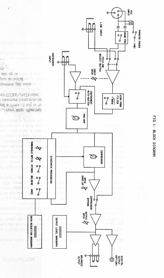
7 SERVICE 1. INTRODUCTION Congratulations on purchasing the Ivory 5050 Mono Preamp & Compressor by TL Audio! The Ivory 2 Series consists of a range of hybrid valve signal processors, which utilise low noise solid state electronics in conjunction with classic valve circuitry to produce audio processing units offering very high quality signal paths with the unique valve audio character. The Ivory 2 Series units offer comprehensive control facilities, whilst remaining straightforward to operate, and represent excellent value for money. The 5050 is a single channel pre-amplifier, accepting a wide range of inputs, coupled to a compressor with fully variable parameters. Twin LED bargraph meters display output level and gain reduction. The optional DO-2 digital output card provides 24 bit A-D conversion of the 5050 analogue output, via a coaxial SPDIF connector. 44.1kHz and 48kHz sample rates are selectable, and an external BNC wordclock input is also provided on the D0-2. The block diagram of the unit is shown in Fig.1. There are three input sources - balanced microphone via an XLR connector, balanced line input via a TRS jack socket, and an instrument jack socket located on the front panel, where it provides a convenient means of patching a guitar or keyboard directly into the processor. The input stage is a hybrid valve circuit, containing one stage of an ECC83/12AX7A dual triode valve, run from a 150V DC stabilised supply. The input gain is governed by a centre-detented control, calibrated for 0dB nominal gain from the line input sources at the centre and providing up to 60dB of microphone gain. The instrument input is also controlled by the input gain potentiometer, and will accept a wide range of sources from passive pickups through to active guitars and keyboards. Phantom power and a 30dB pad are provided on the mic preamp stage, and a switchable 90Hz high pass filter is active on all three inputs. The compressor stage offers variable control of threshold and ratio, with switchable attack & release times and a choice of soft or hard knee compression modes. The compressor is based around TL Audio’s trademark transconductance amplifier stage, and also utilises the other stage of the above-mentioned ECC83/12AX7A valve. An independent gain make-up control is provided, to retain the subjective loudness of a compressed signal, plus an overall master output level control. The output control has a nominal 0dB of gain at its centre, with up to 15dB of further gain available to achieve the high level required for some digital recorders.

The output is via a balanced jack socket at a nominal level of +4dBu. Metering of the output is by an 8 segment LED bargraph. Please read this manual fully before installing or operating the 5050.

2. PRECAUTIONS
The T L Audio 5050 requires very little installation, but like all electrical equipment, care must be taken to ensure reliable, safe operation. The following points should always be observed: - All mains wiring should be installed and checked by a qualified electrician, - Ensure the correct operating voltage is selected on the rear panel before connecting to the mains supply, - Never operate the unit with any cover removed, - Do not expose to rain or moisture, as this may present an electric shock hazard, - Replace the fuse with the correct type and rating only.
Warning: This equipment must be earthed.
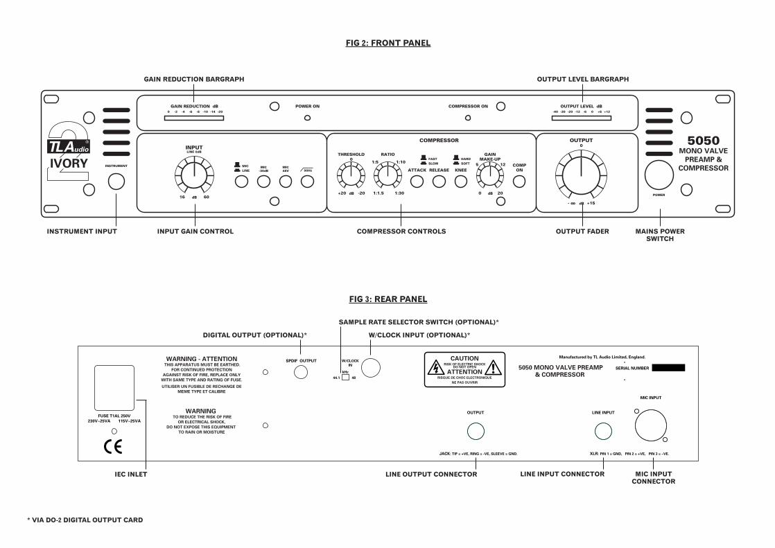
3. INSTALLATION 3.1 AC Mains Supply. The unit is fitted with an internationally approved 3 pin IEC connector. A mating socket with power cord is provided with the unit, wired as follows: Brown: Live. Blue: Neutral. Green/Yellow: Earth (Ground). All mains wiring should be performed by a qualified electrician with all power switched off, and the earth connection must be used. Before connecting the unit to the supply, check that the 5050 is set for the correct mains voltage. The unit is internally set for 110-120V 60Hz or 220-240V 50Hz operation, and should only be changed by an authorised service centre. The mains fuse required is 20mm anti-surge, 1AT rated at 250V. If it is ever necessary to replace the fuse, only the same type and rating must be used. The power consumption of the equipment is 20VA. Warning: attempted operation on the wrong voltage setting, or with an incorrect fuse, will invalidate the warranty. 3.2 Audio Operating Level. The 5050 is equipped with inputs and outputs suitable for connection to a wide variety of other audio equipment. The line level input is via a TRS jack socket, and will support both balanced and unbalanced operation when correctly wired. The output is also a TRS jack socket and will support both balanced and unbalanced operation. 3.3 Microphone Input. The microphone input is via 3 pin female XLR connector, suitable for balanced or unbalanced microphones. The mating connector should be appropriately wired as follows for balanced or unbalanced operation: Balanced inputs: - Pin 1 = Ground (screen). - Pin 2 = Signal Phase (also known as “+” or “hot”).

- Pin 3 = Signal Non-Phase (“-” or “cold”). Unbalanced inputs: - Pin 1 = Ground (screen) - Pin 2 = Signal Phase (“+” or “hot”). - Pin 3 = Signal Ground. 3.4 Line Input. The line level input is via a TRS jack socket, suitable for balanced or unbalanced line sources at a nominal level of -10dBu or +4dBu. The mating connector should be appropriately wired as follows for balanced or unbalanced operation: Balanced inputs: - Screen = Ground (screen). - Tip = Signal Phase (also known as “+” or “hot”). - Ring = Signal Non-Phase (“-” or “cold”). Unbalanced inputs: - Screen = Ground (screen) - Tip = Signal Phase (“+” or “hot”). - Ring = Signal Ground When using unbalanced signals, the signal ground may be obtained by linking the ring and screen in the jack plug. If this connection is not made, a loss in level may result. 3.5 Instrument Input. A 2 pin (mono) jack plug is required, which should be wired as follows: - Tip = Signal Phase (“+” or “hot”). - Screen = Ground.

The instrument input has a 1MΩ impedance and is suitable for direct connection of instruments including guitars, bass guitars and keyboards. Good quality screened cable should be used, particularly for microphone or low level sources, to prevent hum or noise pickup. 3.6 Output. A balanced line output is provided on a 0.25” TRS jack socket, at a nominal level of +4dBu. The mating connector should be appropriately wired as follows for balanced or unbalanced operation: Balanced outputs: - Screen = Ground. - Tip = Signal Phase (“+” or “hot”).
- Ring = Signal Non-Phase (“-” or “cold”). Unbalanced outputs: - Screen = Ground (screen) - Tip = Signal Phase (“+” or “hot”). - Ring = Signal Ground
3.7 Mounting. The 5050 may be free standing, or mounted in a standard 19” rack. Always ensure that the cooling vents on the front and sides are clear of obstruction, and do not subject the unit to an external source of heat (by mounting immediately above a power amplifier, for example). If used free standing, ensure that the equipment is protected against rain and spillage of liquid. 3.8 Rear Panel. The rear panel connectors are identified in Fig.3. Make sure that all settings, mains and audio connections have been made as described above before attempting to operate the equipment. 4. OPERATION
FUSE T1AL 250V
230V~25VA 115V~25VA
CAUTIONRISK OF ELECTRIC SHOCK
DO NOT OPEN
ATTENTIONRISQUE DE CHOC ELECTRONIQUE
NE PAS OUVRIR
Manufactured by TL Audio Limited, England.
SERIAL NUMBER5050 MONO VALVE PREAMP
& COMPRESSOR
W/CLOCK
IN
44.1 48
kHz
SPDIF OUTPUTWARNING - ATTENTION THIS APPARATUS MUST BE EARTHED.
FOR CONTINUED PROTECTION
AGAINST RISK OF FIRE, REPLACE ONLY
WITH SAME TYPE AND RATING OF FUSE.
UTILISER UN FUSIBLE DE RECHANGE DE
MEME TYPE ET CALIBRE
WARNING TO REDUCE THE RISK OF FIRE
OR ELECTRICAL SHOCK,
DO NOT EXPOSE THIS EQUIPMENT
TO RAIN OR MOISTURE
JACK: TIP = +VE, RING = -VE, SLEEVE = GND. XLR: PIN 1 = GND, PIN 2 = +VE, PIN 3 = -VE.
OUTPUT LINE INPUT
MIC INPUT
INSTRUMENT
GAINMAKE-UP
0 20dB
THRESHOLD0
+20 -20dB
RATIO
POWER ON COMPRESSOR ONGAIN REDUCTION dB
1:1.5 1:30
1:5 1:105 12
ATTACK RELEASE KNEECOMP
ON
SOFTHARD
SLOWFAST
LINEMIC
COMPRESSORINPUTLINE 0dB
16 60dB
90HzMIC
-30dBMIC48V
OUTPUT0
- oo +15dB
0 -2 -4 -6 -8 -10 -14 -20
OUTPUT LEVEL dB-40 -30 -20 -12 -6 0 +6 +12
POWER
5050MONO VALVE
PREAMP &
COMPRESSORIVORY
FIG 2: FRONT PANEL
FIG 3: REAR PANEL
GAIN REDUCTION BARGRAPH OUTPUT LEVEL BARGRAPH
INSTRUMENT INPUT COMPRESSOR CONTROLSINPUT GAIN CONTROL OUTPUT FADER MAINS POWERSWITCH
DIGITAL OUTPUT (OPTIONAL)* W/CLOCK INPUT (OPTIONAL)*
SAMPLE RATE SELECTOR SWITCH (OPTIONAL)*
IEC INLET LINE OUTPUT CONNECTOR LINE INPUT CONNECTOR MIC INPUT CONNECTOR
* VIA DO-2 DIGITAL OUTPUT CARD
4.1 Front Panel. The front panel controls are identified in Fig.2. 4.2 Input Selection. The input source is selected by the push button adjacent to the input gain control. It selects either the mic or line inputs. If a connector is plugged into the instrument input, it will take priority over the mic and line inputs, which then become disabled. 4.3 30dB Pad. Occasionally - when using sensitive condenser microphones - the source signal may be too loud for the input preamp. In this situation, to avoid any overloading or distortion of the mic preamp stage, the 30dB pad can be used to reduce the input gain to a more manageable level. The 30dB pad only applies to the microphone input. 4.4 Phantom Power. Phantom power may be applied to the microphone socket by depressing the +48V switch. Condenser microphones require phantom power to operate correctly, but do not attempt to connect any microphone that does not require phantom power, or any other equipment such as a DI box, to an input socket that has phantom power switched on, as damage may result. CAUTION: Never switch phantom power on or off, or plug / unplug a microphone with phantom power applied unless the output level control is turned down. Failure to do so may result in a thump in your
monitor loudspeakers or PA system. 4.5 Microphone Input. When using the 5050 with a microphone source, care should be taken not to apply too much gain at the input. Start with the input gain control set to minimum, and the output master at the mid-point (12 o’clock position). The
input gain can then be gradually increased until the output level LED bargraph illuminates to about 0dB on normal signal level. The master output level should then be adjusted to produce the required output. 4.6 Line Input. A line level signal should already be at about the correct operating level, but this may be checked by monitoring the level on the output meter, with the compressor bypassed and the output gain at 0dB. The input gain should be adjusted until the meter reads about 0dB at normal audio level. 4.7 Instrument Input. The front panel instrument input socket is suitable for low level sources such as hi impedance microphones, pick ups or passive guitars, and higher level sources such as active guitars and keyboards. To cater for this wide variety of sources, the 5050 has a large amount of gain available, and care should be taken to avoid applying excessive input gain with a high level source. 4.8 High Pass (Low Cut) Filter. The high pass filter switch restricts the low frequency response of the preamp, to effectively remove rumble or LF noise from the signal. The filter can be useful in restricting “popping” on vocals or even low frequencies caused by contact with microphone stands or microphone cables. Popping is an undesirable thump that is caused by close-miking certain spoken or sung letters, namely “P” or “B”. These particular letters cause a sudden expulsion of air that can result in an audible thump. As this thump has a lot of low frequency content the high pass filter can help to reduce the problem, as can using a pop filter (a device usually made out of nylon material similar to stockings) suspended in front of the microphone. 4.9 What is Compression? Compression is an essential but often misunderstood process in modern recording. Put simply, compression reduces the difference between the loudest and the quietest levels of an audio signal. This is known as reducing the “dynamic range” of that signal and is a powerful tool for an engineer helping to avoid overloading, distortion problems as well as raising the level of the quieter parts of the audio signal. Before the introduction of compressors the only way this could be achieved was by “gain riding”, whereby an engineer would control the fader manually in order to try and anticipate very large levels (which might distort the signal) or very low levels (which may get lost in noise). The introduction of compression devices meant that this process could be
controlled automatically, allowing the engineer to get on with more productive jobs! Many instruments and voices have a very wide dynamic range that need to be controlled. A singer, for instance, may be projecting quietly one moment and very loudly the next, and unless compression is applied the vocal won’t “sit” correctly in the mix, in addition to the problems of distortion on loud passages and noise on quiet ones. Compressors effectively turn down the loud bits and turn up the quiet bits, to achieve a more even and controllable level. Compressors are often judged by their ability to control the dynamics without creating noticeable audible side effects. Heavy compression can cause the signal to pump or breathe with the onset and release of the compression. Some compressor designs can dull the signal and lose the top end of the signal. The 5050 compressor design, as with other TL Audio compressors, uses a technology based around a transconductance amplifier rather than a VCA design. This transconductance amplifier design is known for being able to retain the full frequency range and natural character of the audio signal, even when compressing the signal quite heavily. The 5050 is also capable of more severe compression based around the optional Hard Knee mode if this is desired. There are other benefits of compression as well as just controlling the peaks and raising the quiet parts. Applied properly, it can add punch and excitement to music, as well as fattening up sounds and creating a more professional sounding recording. With the 5050, you have the added benefit of valve stages in the signal path, which create a warmth and presence just not obtainable with solid state or digital products. 4.10 Why Valve Compression? Valve compression yields a particularly special sound which has become very sought after, particularly with the widespread use of digital products. The reason valve equipment sounds special is due to two things: harmonic distortion and natural compression. When the signal through a valve is increased, it tends to generate a particular type of subtle and desirable distortion, called “second harmonic” distortion. This has the effect of thickening and warming the sound, and the more the level you feed to the valve stages, the more of this harmonic distortion will be produced. You should be able to hear this effect as you increase the input gain on the 5050. Secondly, valves will tend to naturally compress an audio signal, again particularly as the signal level is increased. This itself also contributes to the warmth produced by the 5050. 4.11 Overview of Compressor Operation.
To operate the 5050 successfully, an understanding of each control will help to obtain the best results. If you are unfamiliar with the effect of compression it may help to adjust each individual control to extreme settings and listen to the sonic effect. Generally compressors are used in two different ways: either to enhance the signal and control the dynamic range as unobtrusively as possible, or used more severely to specifically create an effect. 4.12 Threshold. The Threshold is the signal level - measured in dB - above which any compression comes into operation. The Threshold control is variable from +20dB in the fully anticlockwise position to -20dB at the fully clockwise position. Any signal below the Threshold passes through the unit unaffected; while signals above the Threshold are reduced in gain (and are thus ‘compressed’). This does depend to some extent on whether soft or hard knee mode is selected, as the soft knee is more gradual in effect around the Threshold point. Unlike some compressors, the Threshold control on the 5050 starts at a ‘plus’ value in the anti-clockwise position, and decreases to a ‘minus’ value as you rotate the control clockwise. The reason for this is as you turn the Threshold control on the 5050 clockwise (i.e. towards the negative region) then the degree of compression will increase. We think this is logical, whereas the common method of turning the control ‘down’ to achieve more compression is not - but beware, some other compressors may work in the opposite direction! 4.13 Ratio. Once the input signal has crossed the threshold, the degree of gain reduction is determined by the Ratio control. The Ratio control is calibrated in decibels and is simply the change in output level that results from a given change in input level. An uncompressed signal will have a 1:1 compression ratio - every 1dB change in input level results in the same 1dB change in output level. A compression ratio of 1:3, for instance, means that a 3dB change in input level will only give a 1dB change in output level. For more severe compression, simply turn up the Ratio control. The 5050 offers a wide range of ratios from 1:1.5 (gentle compression) through to 1:30 (limiting). Limiting effectively clamps the input signal at the threshold level no matter how much the signal is increased: this can be useful when trying to ensure that the signal doesn’t exceed a certain level - for instance to prevent a digital recorder distorting through overload. 4.14 Attack and Release. The Attack time sets how quickly the compression is applied once the threshold has been exceeded, and the Release time sets how quickly the compression is released (and the signal returns to normal) once the signal
drops back below the threshold. The 5050 Attack and Release controls each allow a choice of ‘Fast’ and ‘Slow’ modes. The Attack times are 0.5mS (Fast) and 20mS (Slow), while the Release control is set for 40mS (Fast) and 2S (Slow). There is an element of automatic operation of the Attack and Release on the 5050: for instance, should a very short transient occur the time constants tend to become shorter, to prevent a slow release leaving a “hole” in the signal after the transient. Also, a fast release setting will be extended by a slow attack setting. The speed of the Attack and Release should in general be able to work with the tempo of the signal. For example if the signal is a snare drum, by monitoring the gain reduction it is possible to set the Release to allow the compression to fully recover (i.e. the gain reduction meter will settle back to 0dB) before the next snare beat. This prevents the second snare beat being reduced in level in comparison to the first. One side-effect of having an incorrect release setting is distortion on low frequency signals, which can particularly occur when using a fast release setting on bass heavy signals - the compressor is forced in and out of compression during one cycle of the waveform, and distortion results. The 5050 has a built-in “Hold” facility which delays the onset of release for approximately 10mS after the input signal falls below the threshold. If distortion is still experienced, a slower release time should be used. 4.15 Knee. The Knee switch enables the 5050 to be operated in two different modes - soft knee or hard knee. Soft knee mode offers a gentle compression curve around the threshold point, and is traditionally employed to yield a more subtle, musical type of compression effect. The hard knee setting causes the full compression ratio to be applied immediately the signal has passed the threshold point, so tends to produce more pronounced and severe compression. 4.16 Gain Make Up. While the subjective sound quality of the signal can be improved by compression, the overall signal level will be reduced when gain reduction is taking place. The Gain Make Up control is designed to boost the compressed signal by between 0 and 20dB, in order to bring back the level to the same loudness as the uncompressed signal. Without this control, comparing the original and compressed signals becomes difficult, since there would be a level drop each time the compressor is switched in: therefore it is normal to adjust the Gain Make Up control so that when the ‘compressor on’ switch is activated, the audio signal remains constant in level. Unlike the Output Level control, the Gain Make Up control is active only when the ‘compressor on’ switch is engaged. Once the Gain Make Up has been

adjusted, use the Output Level control to set the overall output level of the 5050. 4.17 Compressor On. This switch enables or disables the compressor stage, thus allowing an A/B comparison to be made between the original untreated signal and the compressed signal. Any gain make up applied to the signal only becomes active when the “Compressor On” is enabled. An associated status LED indicates when the compressor is active. The Gain Reduction bargraph meter will monitor the level of compression regardless of the compressor stage being active or non active. 4.18 Output Level. The master level control is an output fader, which enables the 5050 output to be matched to the following equipment. The control is calibrated for 0dB at its centre, with a further 15dB of gain available by turning the knob fully clockwise. The additional gain may be useful if the output of the 5050 is connected directly to a digital recorder, which requires a high level of modulation. Note that applying additional gain at the output will not increase the dynamic range of the signal, but will increase the noise level as well as the audio signal being recorded, and should therefore only be used if an output level in excess of the nominal +4dBu is required. 4.19 Bargraph Meters. The 5050 is equipped with twin 8 segment LED bargraph meters. The output (right-hand) meter monitors the audio output from the unit. It has a peak reading characteristic, with fast attack and slower decay. The left-hand meter indicates the gain reduction occurring at the compression stage. It will give a continuous reading, even if the compressor is bypassed. It should be noted that the gain reduction indication is most useful as a measure of the compression of the signal, and therefore does not include the effect of any gain make-up that may be applied. 4.20 Optional DO-2 Digital Output Card. The 5050 is designed to accept the optional D0-2 24 bit digital A to D converter card, to allow easy interfacing with devices such as sound cards and digital recorders. The card feeds the converted 5050 analogue output to the DO-2’s SPDIF phono output. The sample rate is switchable between either
44.1kHz or to 48kHz, and the card can be clocked to an external digital source via the BNC wordclock input. When clocking the DO-2 to an external source the sample rate setting on the DO-2 needs to be set to match the external sample rate, otherwise correct locking may not occur and audible clicking may appear on the digital output. In terms of gain, the DO-2 will generate a signal level of 0dBfs in the digital domain when +18dBu of output level is generated at the balanced line output of the 5050. 5. GETTING STARTED 5.1 Connections. There are various ways that the 5050 can be connected into your audio system. The three most common are: a) As a mic or instrument front end b) Connected to a channel insert point on a mixing desk c) Connected to a group or master insert point on a mixing desk To use the 5050 as a mic or instrument front end, connect the output of the 5050 directly to the line (not mic) input of your console, recorder or sound card. A common mistake is to plug the 5050 line output into the XLR mic input of a console. This will cause the console mic inputs to overload very easily and may result in a loss of quality. Once the output is connected, simply feed your mic or instrument into the relevant input on the 5050. Recording direct to the multitrack recorder (thus bypassing the console) is a common technique these days as it keeps the signal path short, and of the highest quality. No unnecessary console stages are passed through, thus maintaining quality. Many mixers have sockets called ‘insert points’, which allow processors such as dynamics devices and EQs to be patched in-line into the mixer signal path at various points. The mixer’s channel insert point usually ‘sends’ the input signal out directly after the mixer’s preamp stage - allowing connection to the line input of the 5050 - and then returns the processed signal from the line output of the 5050 back into the mixer at the same point in the signal path. This is commonly achieved using a special insert cable (sometimes known as a ‘Y’ lead or split lead - usually a stereo 0.25” jack connector at one end split into two mono jack or XLR connectors - one for send and one for return). The most likely positions that insert points are located on a mixer are in the channel, group and stereo master sections. Patching the 5050 into the channel insert point means that any signal passing through that channel will pass directly though the 5050. Compressing an off-tape signal on mixdown, for instance, can be achieved by connecting the tape machine to the mixer tape

returns, then connecting the 5050 into the relevant console channel insert point. The off-tape signal will then be fed into the 5050’s line input via the mixer insert ‘send’ connection. The line output of the 5050 connects back to the insert ‘return’ connection, thus returning the processed signal to the mixer and ensuring continuous signal flow. Group insert points are used to process sub-grouped signals such as drums or backing vocals. It’s possible to mix a group of voices or instruments to a single group, and then use that group fader to control the overall level, rather than having to adjust each individual voice or instrument level. If you then wish to compress the overall group signal, you can connect a 5050 to the relevant group insert point, using the same ‘send and return’ technique as the channel insert. The optional DO-2 digital card will allow high quality 24 bit A/D conversion of the 5050 mono output on a coaxial SPDIF connector. The DO-2 can feed directly into digital recorders such as Digital Multitrackers, Hard Disk Recorders, DAT Recorders, Minidisc and CD-Recorders, bypassing any A-D conversion stages on the way. When connecting the DO-2’s SPDIF output it is advisable to use cables less than 5 metres in length and of high quality. The digital output can be used simultaneously with the 5050’s analogue output. 5.2 In Use. Having connected the 5050, it’s time to put it into action! Here’s a simple step by step guide:
1. We’ll assume that a condenser microphone is connected to the 5050 mic input, and the +48V phantom power is engaged. The first stage is then to set up the gains of the 5050. With the compressor stage switched out, start with the 5050 input gain at minimum and output gain at 0dB.
2. Gradually bring up the 5050 input gain until a healthy 0dB reading is
achieved on the 5050 output level meter with the chosen source material. If more output is required the output level can be adjusted accordingly without affecting the compression characteristics: remember that digital recorders can require a large amount of output level to drive them to a 0dBfs meter reading.
3. Now depress the Compressor ‘On’ switch, and using the compressor
controls you will need to adjust settings to suit the instrument you are listening to. A good starting point is set the Attack and Release to ‘Fast’, Ratio to 1:3, Knee to ‘Soft’, and Threshold to +20dB.
4. As you start turning the Threshold control clockwise towards 0dB, the
5050 meter should now register that some gain reduction is taking
place. Aim to get around a maximum 3-4dB of gain reduction occurring as a starting point, by lowering the Threshold further if necessary. You should also notice that increasing the Ratio setting causes more gain reduction to occur.
5. When gain reduction is taking place, you should notice that the output
level is reduced. By switching the compressor ‘in’ and ‘out’, you can compare the levels and the subjective sound quality of the original and compressed signals. With the compressor active, use the Gain Make-Up control to set the level so that when disabling the compressor, there is no level shift. This way you can A/B the original and compressed signals without the levels changing.
6. At this stage if you are unfamiliar with compression you should experiment with each control to see how it affects the sound. If in doubt, aim to use compression gently as it can be difficult to compensate for over-compression, if you later decide that too much effect was used. On the other hand there are no rules, so if extreme settings get you the effect you are after, the choice is yours. Let your ears be the guide.
6. SPECIFICATIONS Microphone Input: Electronically balanced. Input impedance greater than 2Kohm. Gain range +16dB to +60dB. Noise -127dBu (EIN with 150 ohm source, 22Hz - 22KHz and maximum gain). 3 pin female XLR connector.
Phantom Power: +48V at 10mA maximum. High Pass Filter: -3dB at 90Hz, 12dB per octave. Balanced Line Input: Electronically balanced, unbalanced compatible, with input impedance greater than 5Kohm. Gain range -20dB to +20dB. Nominal input level +4dBu. Maximum input level +26dBu. 3 pole 0.25” jack socket. Auxiliary Input: Gain control range 40dB. Maximum input level +12dBu. 2 pole 0.25” jack socket. Compressor: Threshold -20dBu to +20dBu, Attack 0.5msec to 20msec, Release 40msec to 2 seconds, Ratio 1:1.5 to 1:30, Gain Make-Up 0 to +20dB, Hard or Soft Knee mode switch. Output Fader: Rotary fader, 0dB at centre, +15dB maximum gain. Output: Balanced. Output impedance 47 ohms. Maximum level +26dBu. 3 pole 0.25” jack socket. Frequency Response:
10Hz to 40KHz, +0, -1dB. Noise: -80dBu, 22Hz to 22KHz, line input selected at 0dBu input and output gain. Dynamic Range: 100dB (Line input @ 0dB gain). Power Requirements: Internally set for 220-240V 50Hz or 110-120V 60Hz operation. Rear panel fuse 20mm, 1AT, 250V. Power consumption 20VA typical. Detachable 3 pin IEC connector, mating connector and cable supplied. Front panel On/Off switch with green LED. Dimensions: 19” rack mounting, 2U high. 483mm wide x 88mm high x 200mm deep. Shipping Weight:
6Kg.
The above specifications are subject to change without notice.

7. SERVICE
Should the 5050 require service, it must be taken or posted to an authorised dealer. Please retain the original packing for possible future use, and ensure the unit is suitably protected during transit. The manufacturer cannot accept responsibility for damage caused during transportation. The 5050 is supported by a limited warranty for a period of one year from the date of purchase. During this period, any faults due to defective materials or workmanship will be repaired free of charge. The warranty excludes damage caused by deliberate or accidental misuse, operation on the incorrect mains voltage, or without the correct type and value of fuse fitted. It is the user’s responsibility to ensure fitness for purpose in any particular application. The warranty is limited to the original purchase price of the equipment, and excludes any consequential damage or loss. Please include proof of purchase date if claiming repair under warranty. For your own records, please complete the following details: Serial Number............................. Date purchased........................... Dealer.........................................