item no. 33.03.158 power analyser umg 96 rm-e … analyser umg 96 rm-e residual current monitoring...
TRANSCRIPT

Doc
. no.
1.0
40.0
81.1
.gc
Power Analyser
UMG 96 RM-EResidual current monitoring (RCM)
Operating instructions and technical data
Item
no.
33.
03.1
58
Janitza electronics GmbHVor dem Polstück 1D-35633 LahnauSupport tel. 0049 6441 9642-22Fax 0049 6441 9642-30E-mail: [email protected]: http://www.janitza.com
ww
w.ja
nit
za.c
om
Power Analyser
MO
D10
0 (2
0-25
0V)

2
UMG 96RM-E
Content
General 4Inspection on receipt 6
Scope of delivery – UMG 96RM-E (RCM) 7Available accessories 7
Product description 8Proper use 8Performance characteristics – UMG 96RM-E 10Measuring process 11Operating concept 11GridVis network analysis software 11Connection variants 12
Mounting 13Installation 15
Power supply 15Measuring voltage 16Current measurement via I1 to I4 22Residual current measurement (RCM) via I5, I6 31Temperature measurement input 33RS485 interface 34Ethernet interface 37Digital in-/outputs 38LED status bar 42
Operation 44Display mode 44Programming mode 44Parameters and measured values 46
Configuration 48Connecting the supply voltage 48Current and voltage transformers 48Programming the current transformer for I1 to I3 50Programming the voltage transformer 51Programming parameters 52TCP/IP configuration 53RS485 device address (Addr. 000) 56RS485 baud rate (Addr. 001) 56MODBUS gateway (Addr. 002) 57User password (Addr. 050) 57
Parameter 58Mean value 58Averaging method 58Min. and max. values 58Mains frequency (Addr. 034) 59Energy meter 60Reset energy meter (Addr. 507) 60Harmonics 61Measured value rotation 62Measured value indocations 62Phase sequence 64LCD contrast (Addr. 035) 64Backlight 64Time recording 65Operating hours meter 66
3
UMG 96RM-E
Serial number (Addr. 754) 66Recordings 67
Putting into service 68Connecting the supply voltage 68Applying the measuring-circuit voltage 68Applying the measuring-circuit voltage 68Applying the residual current 69Phase sequence 69Check phase assignment 69Checking the energy measurement 69Checking the measurement 70Checking the individual outputs 70Checking the total power outputs 70
RS485 interface 71Digital outputs 73
Impulse output 75Service and maintenance 80
Service 80Device calibration 80Calibration intervals 80Firmware update 81Battery 81Battery monitoring function 82Replacing the battery 83
Error/warning messages 84
Technical data 90Function parameters 98Table 1 – Parameter list 100Table 2 - Modbus address list 104Number formats 107Dimension diagrams 108
Measured value displays overview 110Declaration of conformity 116Connection example 1 117Connection example 2 118Basic functions quick guide 119TCP/IP addressing quick guide 120

4
UMG 96RM-E
Comments on the operating manual
We welcome your comments. In the event that anything in this operating manual seems unclear, please let us know and send us an EMAIL to: [email protected]
Meaning of the symbols
The following pictograms are used in the operating manual at hand:
General
Copyright
This operating manual is subject to the legal requirements for copyright protection and may not be, either in whole or in part, photocopied, reprinted, or reproduced by mechanical or electronic means, or in any other manner be duplicated or redistributed without the legally binding, written agreement of
Janitza electronics GmbH, Vor dem Polstück 1,D 35633 Lahnau, Germany.
Trademarks
All trademarks and their resulting rights belong to the respective holders of these rights.
Disclaimer
Janitza electronics GmbH takes no responsibility for errors or defects within this operating manual and takes no responsibility for keeping the contents of this operating manual up to date.
c Dangerous voltage! Danger to life or risk of serious injury. Disconnect system and device from power supply before beginning work.
m Caution!Please fo l low the documentat ion. This symbol warns of possible dangers that can ar ise dur ing insta l lat ion, commissioning and use.
C Note!

5
UMG 96RM-E
Instructions for use
Please read the operating manual at hand as well as all other publications that must be drawn from for working with this product (in particular for the installation, operation or maintenance).
Follow all safety regulations and warning information. If you do not follow the information, it can result in bodily injury and/or damage to the product.
Any unauthorized changes or use of this device, which transcend the mechanical, electrical or otherwise stated operating limitations, can result in bodily injury or/and damage to the product.
Any of such unauthorized changes constitute "misuse" and/or "negligence" in terms of the warranty for the product and therefore eliminates the warranty for covering any potential damage resulting from this.
This device is to be operated and maintained exclusively by specialized personnel.
c If the device is not operated according to the operating manual, protection is no longer ensured and danger can come from the device.
m Conductors made from single wires must be fitted with wire-end ferrules.
m Only pluggable screw terminals with the same number of poles and the same type of construction are permitted to be connected together.
Specialized personnel are persons, that based on their respective training and experience, are qualified to recognize risks and prevent potential dangers that can be caused by the operation or maintenance of the device.
Additional legal and safety regulations required for the respective application are to be following during the use of the device.

6
UMG 96RM-E
Inspection on receipt
The prerequisites of faultless, safe operation of this device are proper transport and proper storage, set-up and assembly, as well as careful operation and maintenance. If it can be assumed that risk-free operation is no longer possible, the unit must be immediately put out of operation and secured against being put back into operation again.The packing and unpacking must be carried out with the customary care without the use of force and only using suitable tools. The devices should be visually checked for flawless mechanical condition. It can be assumed that risk-free operation is no longer possible if the device, for example,
• has visible damage • no longer works despite the mains power supply
being intact• has been exposed to long-term adverse conditions
(e.g. storage outside the permissible climate limits without being adapted to the room climate, condensation etc.) or rough handling during transportation (e.g. fall from a height, even if there is no visible external damage etc.)
• Please check the delivered items for completeness before you start installing the device.
C All screw-type terminals included in delivery are attached to the device.
Concerning these operating instructions
These operating instructions are a part of the product.• Read the operating instructions before using
the device.• Keep the operating instructions throughout the entire
service life of the product and have them readily available for reference.
• Pass the operating instructions on to each subsequent owner or user of the product.

7
UMG 96RM-E
Scope of delivery – UMG 96RM-E (RCM)
Number Part no. Description1 52.22.036 UMG 96RM-E2 52.22.251 Mounting clips.1 33.03.158 Operating instructions.1 51.00.116 CD with following content.
- GridVis programming software- GridVis functional description
1 10.01.855 Screw-type terminal, pluggable, 2-pole (auxiliary power)1 10.01.849 Screw-type terminal, pluggable, 4-pole (voltage measurement)1 10.01.871 Screw-type terminal, pluggable, 6-pole (current measurement I1-I3)1 10.01.875 Screw-type terminal, pluggable, 2-pole (current measurement I4)1 10.01.865 Screw-type terminal, pluggable, 10-pole (digital/analogue inputs/outputs)1 10.01.857 Screw-type terminal, pluggable, 2-pole (RS 485)1 10.01.859 Screw-type terminal, pluggable, 3-pole (Digital/impulse output)1 08.01.505 Patch cable 2m, coiled, grey (connection UMG 96RM-PC/Switch)1 52.00.008 RS485, external terminating resistor, 120 ohm
Available accessories
Part no. Description21.01.058 Lithium battery CR2032, 3V (approval i.a.w. UL 1642)29.01.907 Seal, 96 x 9615.06.015 Interface converter RS485 <-> RS23215.06.025 Interface converter RS485 <-> USB

8
UMG 96RM-E
Product description
Proper useThe UMG 96RM-E is intended for the measurement and calculation of electrical parameters such as voltage, current, power, energy, harmonics etc. in building installations, on distribution units, circuit breakers and busbar trunking systems. The UMG 96RM-E is suitable for integration into fixed and weatherproof switch panels. Conductive switch panels must be earthed.
Measured voltage and measured current must derive from the same network.The measurement results can be displayed and can be read out and further processed via the RS485 interface.
The voltage measurement inputs are designed for measurements in low voltage networks, in which rated voltages of up to 300V relative to earth and surges in overvoltage category III can occur.
The current measurement inputs I1–I4 of the UMG 96RM-E are connected via external ../1A or ../5A current transformers.
By continuously monitoring the residual currents (RCM) of an electrical system via the inputs I5 and I6, warning pulses can be triggered if a response threshold is exceeded. Using these, the system operator can be alarmed before a protective equipment reacts. The UMG 96RM-E does not provide protection against and electric shock!
The residual current measuring is done via the current measurement inputs I5 and I6 via an external residual current transformer with a rated current of 30 mA.
Measurements in medium and high-voltage networks is always done via current and voltage transformers.
m The residual current measuring monitors residual currents via external current transformers and can trigger a warning impule when a response threshold is exceeded. Thus, the device is NOT an independent protective device!

9
UMG 96RM-E
The UMG 96RM-E can be used in industrial and domestic settings.
Device characteristics• Supply voltage:
20V - 250V (45..65Hz) or DC 20V - 300V• Frequency range: 45-65Hz
Device functions• 3 voltage measurements, 300V• 4 current measurements
(via current transformers ../5A or ../1A) • 2 residual current measurements
(via residual current transformers ../30mA) or optionally 2 temperature measurements
• RS485 interface, Ethernet• 2 digital outputs and additional 3 digital
inputs/outputs• Clock and memory function
10
UMG 96RM-E
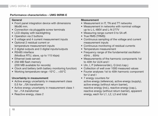
Performance characteristics – UMG 96RM-E
General• Front panel integration device with dimensions 96x96 mm.• Connection via pluggable screw terminals• LCD display with backlighting• Operation via 2 buttons• 3 voltage and 4 current measurement inputs• Optional 2 residual current or temperature measurement inputs• 2 digital outputs and 3 digital inputs/outputs• RS485 interface (Modbus RTU, slave, up to 115 kbps)• Ethernet (web server) • 256 MB flash memory (200 MB available for records)• Clock and bettery (with battery monitoring function)• Working temperature range -10°C .. +55°C
Uncertainty in measurement• Active energy uncertainty in measurement class 0.5 for ../5A transformer• Active energy uncertainty in measurement class 1 for ../1A transformer• Reactive energy, class 2
Measurement• Measurement in IT, TN and TT networks• Measurement in networks with nominal voltage up to L-L 480V and L-N 277V• Measuring range current 0 to 5A eff.• True RMS (TRMS) • Continuous sampling of the voltage and current measurement inputs• Continuous monitoring of residual currents• Temperature measurement• Frequency range of the fundamental oscillation 45Hz .. 65Hz• Measurements of the harmonic components 1st to 40th for ULN and I• Uln, I, P (reference/del.), Q (ind./cap.)• Collection of well over 1000 measured values• Fourier analyses 1st to 40th harmonic component for U and I• 7 energy counters for active energy (reference), active energy (supply), active energy (without return barrier), reactive energy (ind.), reactive energy (cap.), reactive energy (without return barrier), apparent energy, each for L1, L2, L3 and total
11
UMG 96RM-E
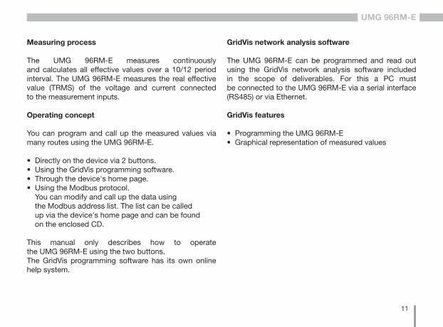
Measuring process
The UMG 96RM-E measures continuously and calculates all effective values over a 10/12 period interval. The UMG 96RM-E measures the real effective value (TRMS) of the voltage and current connected to the measurement inputs.
Operating concept
You can program and call up the measured values via many routes using the UMG 96RM-E.
• Directly on the device via 2 buttons.• Using the GridVis programming software.• Through the device's home page.• Using the Modbus protocol.
You can modify and call up the data using the Modbus address list. The list can be called up via the device's home page and can be found on the enclosed CD.
This manual only describes how to operate the UMG 96RM-E using the two buttons.The GridVis programming software has its own online help system.
GridVis network analysis software
The UMG 96RM-E can be programmed and read out using the GridVis network analysis software included in the scope of deliverables. For this a PC must be connected to the UMG 96RM-E via a serial interface (RS485) or via Ethernet.
GridVis features
• Programming the UMG 96RM-E• Graphical representation of measured values
12
UMG 96RM-E
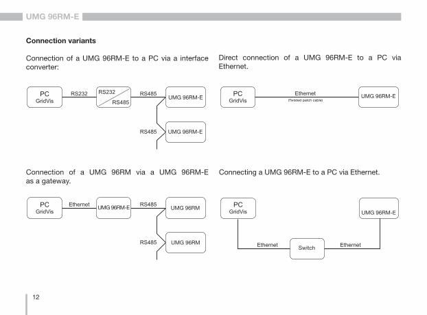
Connection variants
Connection of a UMG 96RM-E to a PC via a interface converter:
Connection of a UMG 96RM via a UMG 96RM-E as a gateway.
Direct connection of a UMG 96RM-E to a PC via Ethernet.
(gedrehtes Patchkabel)
UMG 96RM-E
UMG 96RM-E
(gedrehtes Patchkabel)
UMG 96RM
UMG 96RM
UMG 96RM-E
(gedrehtes Patchkabel)UMG 96RM-E
Connecting a UMG 96RM-E to a PC via Ethernet.(gedrehtes Patchkabel)
UMG 96RM-E
Switch
(Twisted patch cable)

13
UMG 96RM-E
Mounting
Position of installation
The UMG 96RM-E is suitable for integration into fixed and weatherproof switch panels. Conductive switch panels must be earthed.
Mounting position
To ensure adequate ventilation, the UMG 96RM-E must be installed vertically. There should be separation above and below of at least 50mm with 20mm space to the sides.
Front panel section
Cut-out size: 92+0.8 x 92+0.8 mm.
m Failure to meet the minimum clearances can destroy the UMG 96RM-E at high ambient temperatures!
Fig. mounting position UMG 96RM-E (View from rear)

14
UMG 96RM-E
Mounting
The UMG 96RM-E is fixed using the mounting clips found on the side of the switch panel. Before inserting the device, they should be moved out of the way in a horizontal lever using a screwdriver, for example.
Fig. side view UMG 96RM-E with mounting clips. Loosening the clips is done using a screwdriver and a horizontal lever effect.
Mounting plate
Fixing screw
ScrewdriverMounting clips
Contacting of the fixing screws to the mounting plate: Tighten with maximum two further turns for the installation
The fastening is then done when the device is pushed in an the clamps lock in place when the screws are tightened.
• Please tight the fixing screws until they contact the mounting plate easily.
• Tighten with two further turns, the clamping screws (are the screws tightened too much, the mounting bracket will be destroyed)

15
UMG 96RM-E
Installation
Power supply
The 96RM-E needs a supply voltage to operate. The supply voltage is connected on the rear of the device via terminal blocks.
Before connecting the supply voltage, ensure that the voltage and frequency correspond to the details on the ratings plate!The supply voltage must be connected through a UL/IEC approved fuse (6A, type C).
Fig. connection example of the supply voltage to a UMG 96RM
Circuit breaker
Fuse
N
L
m • If installed in a building, a disconnector or circuit-breaker must be provided for the supply voltage.
• The disconnector must be installed near the device and easily accessible to the user.
• The switch must be marked as the circuit breaker for this device.
• Voltages which are over the permitted voltage range can destroy the device.

16
UMG 96RM-E
Measuring voltage
You can use the UMG 96RM-E to measure voltage in TN-, TT-, and IT systems.The voltage measurement in the UMG 96RM-E is designed for the overvoltage category 300V CAT III (rated impulse voltage 4 kV).
Fig. schematic diagram - measurements in three-phase 4-wire systems.
Fig. schematic diagram - measurements in three-phase 3-wire systems.
In systems without N, the measurements which require an N are to a calculated N.
DC
AC/DC
PE
277V/480V 50/60HzL2
L3
N
L1
Auxiliary power
Measuring voltage
4M 4M 4M 4M
V1 V3V2 VN
UMG 96RM
480V 50/60Hz
DC
AC/DC
L2
L3
Auxiliary power
Measuring voltage
4M 4M 4M 4M
V1 V3V2
System earthing
Impedance
L1
VN
UMG 96RM

17
UMG 96RM-E
Network nominal voltage
Lists of networks and their nominal network voltages in which the UMG 96RM-E can be used.
Three-phase, 4-wire systems with earthed neutral conductor.
Maximum system nominal voltage
UL-N / UL-L
66V / 115V120V / 208V127V / 220V220V / 380V230V / 400V240V / 415V260V / 440V277V / 480V
Fig. table for network nominal voltages i.a.w. EN60664-1:2003 suitable for the voltage measurement inputs.
Three-phase, 3-wire systems, unearthed.
Fig. table for network nominal voltages i.a.w. EN60664-1:2003 suitable for the voltage measurement inputs.
Maximum system nominal voltage
UL-L
66V 120V 127V 220V 230V 240V 260V 277V 347V380V400V415V440V480V
18
UMG 96RM-E
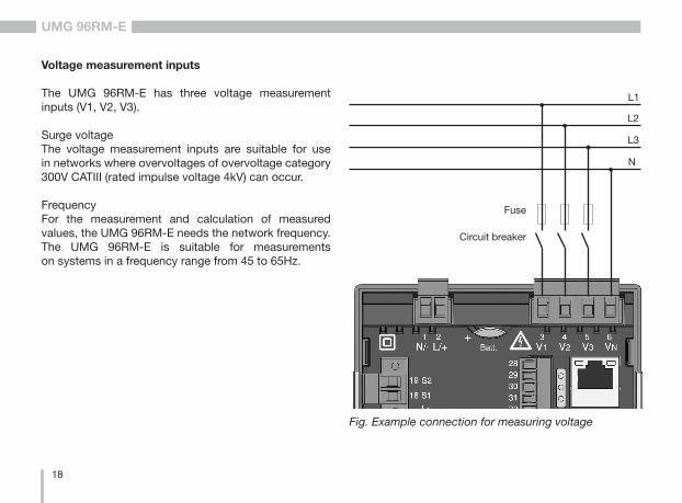
Voltage measurement inputs
The UMG 96RM-E has three voltage measurement inputs (V1, V2, V3). Surge voltageThe voltage measurement inputs are suitable for use in networks where overvoltages of overvoltage category 300V CATIII (rated impulse voltage 4kV) can occur.
FrequencyFor the measurement and calculation of measured values, the UMG 96RM-E needs the network frequency. The UMG 96RM-E is suitable for measurements on systems in a frequency range from 45 to 65Hz.
Fig. Example connection for measuring voltage
Circuit breaker
Fuse
L2
L3
N
L1

19
UMG 96RM-E
When connecting the voltage to be measured, the following must be observed:
• A suitable isolation device must be fitted to disconnect and de-energise the UMG 96RM-E.
• The isolation device must be placed in the vicinity of the UMG 96RM-E, be marked for the user and easily accessible.
• Use a UL/IEC approved circuit breaker 10A (Type C) for the over-current protection and isolation device.
• The over-current protection must have a rated value which is suitable for the short circuit current at the connection point.
• Measured voltage and measured current must derive from the same network.
c Caution!Voltages which exceed the per-m i t t e d n e t w o r k r a t e d v o l t a g e must be connected via a voltage transformer.
c Caution!The UMG 96RM-E is not suitable for measuring DC voltages.
c Caution!The voltage measurement inputs on the UMG 96RM-E are dangerous if touched!

20
UMG 96RM-E
Wiring diagrams, voltage measurement
L1
L2
L3N
V1 V2 V3 VN
• 3p 4w (Addr. 509= 0), factory setting
L1
L2
L3N
V1 V2 V3 VN
• 3p 4wu (Addr. 509 = 1)
• 3p 4u (Addr. 509 = 2)
L1
L2
L3
V1 V2 V3 VN
L1
L2
L3
V1 V2 V3 VN
• 3p 2u (Addr. 509 = 5)
Fig. System with three line conductors and neutral conductor.
Fig. System with three line conductors and neutral conductor. Measurement using a voltage transformer.
Fig. System with three line conductors without neutral conductor. Measurements which require a N are based on a calculated N.
Fig. System with three line conductors without neutral conductor. Measurement using a voltage transformer. Measurements which require a N are based on a calculated N.

21
UMG 96RM-E
• 1p 2w (Addr. 509 = 6)
L1
L2
V1 V2 V3 VN
L1
L2
L3N
V1 V2 V3 VN
• 2p 4w (Addr. 509 = 3)
L1
N
V1 V2 V3 VN
• 1p 2w1 (Addr. 509 = 4)
Fig. TN-C system with single-phase three-wire connection. The null is taken from the voltage measurement input V3's measured value and not calculated.
Fig. The values obtained from the voltage measurement inputs V2 and V3 are taken to be null and not calculated.
Fig. System with uniform phase loading. The measured values for the voltage measurement input V2 are calculated.
L1L2L3
L1L2L3
L1L2L3
V1 V2 V3 VN
N
• 3p 1w (Addr. 509 = 7)
Fig. 3 systems with uniform phase loading. The not connected measured values L2/L3, L1/L3, and L1/L2 of each system are calculated.

22
UMG 96RM-E
Current measurement via I1 to I4
The UMG 96 RM-E is designed to have current transformers with secondary currents from ../1A and ../5A attached cia terminals I1-I4. The factory default for the current transformer ratio is 5/5A and must be adapted to the current transformer employed if necessary. Direct measurement without a current transformer is not possible using the UMG 96RM-E. Only AC currents can be measured - DC currents cannot.
Via the current measurement input I4 only an apparent current measurement is carried out thanks to the lack of a multiplier. Power measurements are therefore not possible using the I4 input.
c Caution!The current measurement inputs are dangerous to touch.
L2
L3
N
L1
Fig. Current measurement (I1-I3) via current transformers (connection example)
Load
m The attached screw terminal has to be fixed sufficiently with two screws on the device!

23
UMG 96RM-E
m Caution! The UMG 96RM-E is not suitable for measuring DC voltages.
c Earthing of current transformers!If a connection is provided for the earthing of secondary windings then this must be connected to the earth.
C It is not necessary to configure a connection schematic for the I4 measurement input.
L2 L3 NL1
Fig. Current measurement (I4) via current transformer (connection example)
Load

24
UMG 96RM-E
Current direction
The current direction can be individually corrected via the existing serial interface or on the device for each phase.If incorrectly connected, a subsequent re-connection of the current transformer is not required.
When residual current measurements (RCM) are being carried out, there is no direction sensitive difference in the residual currents on the network or load side (not directionally sensitive).
c Current transformer connections!The secondary connection of the current transformer must be short-circuited on this before the current feed to the UMG 96RM-E is disconnected!If a test switch, which automatically short-circuits the secondary wires of the current transformer, is available then it is sufficient to set this to the "Test" position insofar as the short-circuiting device has been checked beforehand.
c Open-circuit current transformers!High voltage spikes that are dangerous to touch can occur on current transformers that are driven with open-circuit secondary windings!W i t h " s a f e o p e n - c i rc u i t c u r re n t transformers" the winding insulation is rated such that the current transformer can be driven open. However, even these current transformers are dangerous to touch when they are driven open-circuit.
c Caution!A residual current measurement is done using the terminals I5 and I6 (see page 30). There is no directional sensitivity of the residual currents on the network or load sides (not directionally sensitive).
c Earthing of current transformers!If a connection is provided for the earthing of secondary windings then this must be connected to the earth.

25
UMG 96RM-E
c Caution! The UMG96RM is only approved for a current measurement using the current transformer.

26
UMG 96RM-E
Wiring diagrams, current measurement (I1-I3)
L1
L2
L3N
I1 I2 I3
• 3p 4w (Addr. 510= 0), factory setting • 3p 2i (Addr. 510 = 1)
L1
L2
L3N
I1 I2 I3
L1
L2
L3
I1 I2 I3
• 3p 2i0 (Addr. 510 = 2)
L1
L2
L3
I1 I2 I3
• 3p 3w3 (Addr. 510 = 3)
Fig. Measurement in a three-phase network with non-uniform load.
Fig. The measured values for the current measurementinput I2 are calculated.
Fig. System with uniform phase loading. The measured values for the current measurement input I2 are measured.
Fig. Measurement in a three-phase network with non-uniform load.

27
UMG 96RM-E
• 1p 2i (Addr. 510 = 6)
I1 I2 I3
L1
L2
L1
L2
L3N
I1 I2 I3
• 3p 3w (Addr. 510 = 4)
• 1p 2w (Addr. 510 = 7)
L1
N
I1 I2 I3
L1
L2
L3N
I1 I2 I3
• 2p 4w (Addr. 510 = 5)
Fig. The null is taken from the current measurement input I3's measured value and not calculated.
Fig. The null is taken from the current measurement inputs I2 and I3 measured values and not calculated.
Fig. System with uniform phase loading. The measured values for the current measurement input I2 are calculated.
Fig. System with uniform phase loading. The measured values for the current measurement inputs I2 and I3 are calculated.
28
UMG 96RM-E
Wiring diagrams, current measurement (I1-I3)
L1L2L3
I1 I2 I3
L1L2L3
L1L2L3
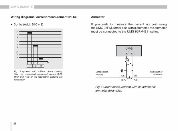
• 3p 1w (Addr. 510 = 8)
Fig. 3 systems with uniform phase loading. The not connected measured values I2/I3, I1/I3 and I1/I2 of the respective systems are calculated.
Ammeter
If you wish to measure the current not just using the UMG 96RM, rather also with a ammeter, the ammeter must be connected to the UMG 96RM-E in series.
Fig. Current measurement with an additional ammeter (example).
UMG
S2
IS1
EinspeisungSupply
VerbraucherConsumer
A
(k)S1 S2(l)
P2(L)(K)P1

29
UMG 96RM-E
Total current measurement
If the current measurement is done via two current transformers, the overall transformation ratio of the current transformers must be programmed into the UMG 96RM-E.
Example: The current is measured via two current transformers. Both current transformers have a transformation ratio of 1000/5A. The total measurement is done using a total current transformer 5+5/5A.
The UMG 96RM-E must then be setup as follows:Primary current: 1000A + 1000A = 2000ASecondary current: 5A
Fig. Current measurment using a total current transformer (example).
UMG
S2
IS1
P1 P2
Einspeisung 1Supply 1
Einspeisung 2Supply 2
1P1
1P2
(K)
(L)(k)(l)
1S2
1S1
1S1 1S2 2S1 2S2
2S1
2S2
(k)(l)
(K)(L)
2P1
2P2
Verbraucher AConsumer A
Verbraucher BConsumer B

30
UMG 96RM-E
Analog inputs
The UMG 96RM-E has 2 analog inputs which can be used for one residual current measurement or one temperature measurement. The measurement is done using terminals 32-34 (input 1) or 35-37 (input 2).
The analog inputs can be used for residual current or temperature measurement in accordance with the following table:
Measurement Terminal
Temperature 32/34 (input 1) and35/37 (input 2)
Residual current 33/34 (input 1) and36/37 (input 2)
c Attention! Operating equipment connected to the analogue inputs must exhibit reinforced or double insulation from mains supply circuits!
Example - temperature sensor:A temperature sensor in close proximity to non-isolated mains cables should measure within a 300V CAT III network.Remedy:The temperature sensor must be equipped with reinforced or double insulation for 300V CAT III. This equates to a test voltage for the temperature sensor of 3000V AC (duration 1 min.).
Example - residual current transformer:A residual current transformer should measure on isolated mains cables within a 300V CAT III network.Remedy:The insulation of the mains cables and the insulation of the residual current transformer must fulfil the basic insulation requirements for 300V CAT III. This equates to a test voltage of 1500V AC (duration 1 min.) for the insulated mains cables and a test voltage of 1500 V AC (duration 1 min.) for the residual current transformer.

31
UMG 96RM-E
Residual current measurement (RCM) via I5, I6
The UMG 96RM-E is for use as a residual current monitoring device (RCM), suitable for monitoring AC, pulsing DC, and DC.
The UMG 96RM-E can measure residual currents in accordance with IEC/TR 60755 (2008-01)
of type A and
type B.
The connection from suitable external residual current transformers with a rated current of 30 mA is done via the residucal current transformer inputs I5 (terminals 33/34) and I6 (terminals 36/37).
Fig. Connection example residual current measurement via current transformers
L2 L3N L1
Load
PE
C Residual current transformer ratioThe GridVis software included with delivery can be used to individually program the residual current transformer inputs' transformer ratios.

32
UMG 96RM-E
C I t is not necessary to conf igure a connection schematic for residual current inputs I5 and I6.
Fig. Example UMG96RM-E with residual current monitoring via measuring inputs i5/I6.
L1 L2 L3 N I1 I2 I3
L1
L2
L3
PENN
PE
UMG 96RM-E (RCM)M3~
I5 I6I4
Residualcurrent transformer
Residual current transformer
Connection example, residual current monitoring

33
UMG 96RM-E
Temperature measurement input
The UMG 96RM-E has two temperature measuring inputs. The temperature is measured via terminals 32/34 (input 1) and 35/37 (input 2).
Do not exceed the total resistance load (sensor + cable) of 4kOhm.
Fig. Example, temperature measurement with a Pt100
PT100
PT100
m Use a shielded cable to connect the temperature sensor.

34
UMG 96RM-E
RS485 interface
In UMG 96RM-E, the RS485 interface is designed as a 2 pin plug contact, which communicates via the Modbus RTU protocol (also see Parameter programming).
Correct
Incorrect
Termination resistors
The cable is terminated with resistors (120Ohm, 1/4W) at the beginning and at the end of a segment.
The UMG 96RM-E does not contain any termination resistors.
Terminal strip in the cabinet.
Device with RS485 interface.(without terminating resistor)
Device with RS485 interface. (with terminating resistor on the device)
RS485 interface, 2-pole plug contact
RS485 interface, 2-pole plug contact with terminating resistor (Item no. 52.00.008)
AB
120 Ω RS485 bus
AB
RS485 bus

35
UMG 96RM-E
Screening
Twisted screened cable should be used for connections via the RS485 interface.
• Earth the screens of all cables that lead to the cabinet, upon entering the cabinet.
• Connect the screens over a generous area and in a manner that will conduct well, to a low-noise earth.
• Gather the cables mechanically above the earthing clamp in order to avoid damage due to cable movements.
• Use suitable cable glands to feed the cables into the cabinet - for example armoured conduit couplings.
Cable type
The cable used must be suitable for an environmental temperature of at least 80°C.
Recommended cable types:Unitronic Li2YCY(TP) 2x2x0.22 (from Lapp Kabel)Unitronic BUS L2/FIP 1x2x0.64 (from Lapp Kabel)
Maximum cable length
1200m at a baud rate of 38.4k.
Fig. Screening procedure at cabinet entry.
Cable
Strain relief
Screen braid of the cable
Earthing clamp
Low-noise earth

36
UMG 96RM-E
Bus structure
• All devices are connected in a bus structure (line) and each device has its own address within the bus (see also Parameter programming).
• Up to 32 subscribers can be connected together in a single segment.
• The cable is terminated with resistors (bus termination 120Ohm, 1/4W) at the beginning and at the end of a segment.
• With more that 32 subscribers, repeaters (amplifiers) must be used to connect the individual segments.
• Devices for which the bus connection is switched on must be under current.
• It is recommended that the master be placed at the end of a segment.
• If the master is replaced with a bus connection, the bus must be switched off.
• Replacing a slave with a bus connection that is either switched on or de-energised can destabilise the bus.
• Devices that are not connected to the bus can be replaced without destabilising the bus.
Fig. Bus structureSlaveSlaveSlave
Slave Slave Slave Repeater
Slave Slave Slave Slave
MasterPower supply necessary
Bus terminator onT
T
TT
T

37
UMG 96RM-E
Ethernet interface
The Ethernet network settings should be specified by the network administrator and set on UMG 96RM-E accordingly. If the network settings are not known, the UMG 96RM-E may not be integrated into the network through the patch cable.
m Caution! Connection of the UMG96RM-E to the Ethernet may only be carried out after discussion with the network administrator!
PC / SwitchEthernet
Connection
m Caution! The UMG 96RM-E is factory-programmed for the dynamic allocation of the IP settings (DHCP mode).Settings can be changed as described in TCP/IP Configuration or, for example, via an appropriate Ethernet connection by means of GridVis software.

38
UMG 96RM-E
Digital in-/outputs
The UMG 96RM-E has 2 digital outputs and 3 optional digital inputs or outputs, which are divided into two groups (see figure). This means that only entire group 2 (connection 28 to 31) operate either as input or output; a different allocation within the group is not possible! The status of the inputs or outputs of Group 2 is signalled via the corresponding LED (see LED status bar).
Digital outputs
These outputs are galvanically separated from the analysis electronics using optocouplers. The digital outputs have a joint reference.
• The digital outputs can switch AC and DC loads.• The digital outputs are not short-circuit proof.• Connected cables that are longer than 30m must
be shielded when laid.• An external auxiliary voltage is required.• The digital outputs can be used as impulse outputs.• The digital outputs can be controlled via Modbus.• The digital outputs can display the results
of comparators.
~
~Group 2
Group 1
Fig. Connection digital / pulse outputs

39
UMG 96RM-E
C When using the digital outputs as pulse outputs the auxiliary voltage (DC) must have a max. residual ripple of 5%.
C Functions for the digital outputs can be adjusted clearly in the GridVis software provided in the scope of deliverables. A connection between the UMG 96RM-E and the PC via an interface is required for the use of the GridVis software.
DC connection example
Fig. Example for two relays connected to the digital outputs
K2
External Auxiliary voltage
+
24V DC
-
K1
DC
DC
28
29
30
31
Digital Ouput 3
Digital Ouput 4
Digital Ouput 5
13
14
15
Digital Ouput 1
Digital Ouput 2
UMG 96RM-E
Gro
up 1
: G
roup
2:
m Caution! Digital outputs are not short-circuit proof.

40
UMG 96RM-E
Digital inputs
When allocating Group 2 as inputs, the UMG96 RM-E has three digital inputs to each of which you can connect one signal transducer. When a signal is present, the corresponding LED lights up green.
An input signal is detected on a digital input if a voltage of at least 10V and maximum 28V is applied and where a current of at least 1mA and maximum 6mA flows at the same time. Wiring longer than 30m must be screened.Note the correct polarity of the supply voltage!
- +
24V DC
S1
S2
External Auxiliary voltage
28
29
30
31
2k21
2k21
2k21
2k21
2k21
2k21
2k21
DigitalInput 1
DigitalInput 2
DigitalInput 3
UMG 96RM-EDigital inputs 1-3
Fig. Example for the connection of external switch contacts S1 and S2 to digital inputs 1 and 2.
- +
Fig. Connectionexample for digital inputs.
Group 2
S3

41
UMG 96RM-E
28
29
30
31
2k21
2k21
2k21
2k21
2k21
2k21
2k21
DigitalInput 1
DigitalInput 2
DigitalInput 3
UMG 96RM-EDigital inputs 1-4
- +
24V DC
External Auxiliary voltage
S0 pulse transducer
1.5k
S0 pulse input
You can connect an S0 pulse transducer per DIN EN62053-31 to any digital input.
This requires an auxiliary voltage with an output voltage in the range 20 .. 28V DC and a resistor of 1.5kOhm.
Fig. Example for the connection of an S0 pulse transducer to digital input 1.

42
UMG 96RM-E
LED status bar
The different statuses of the inputs and outputs are displayed via the LED status bar on the rear of the device.
Digital inputsThe LED assigned to a respective input lights up green when a signal of at least 1mA flows on this interface.
Digital outputsThe LED assigned to a respective output lights up red when the output is set as enabled - regardless of whether there is a continuing connection to this interface.
Digital in-/output 1
Digital in-/output 2
Digital in-/output 3
LED
sta
tus
bar
Fig. LED status bar for inputs and outputs

43
UMG 96RM-E

44
UMG 96RM-E
Operation
The UMG 96RM-E is operated via buttons 1 and 2 with the following functions:• briefly pressing button 1 and 2:
next step (+1)• pressing and holding button 1 and 2:
previous step (-1)Measured values and programming data are displayed on an LCD display.
There are display and programming modes. You can avoid an unintentional change of programming data by entering a password.
Display mode
In display mode, you can scroll through the programmed measured values by pressing buttons 1 and 2. When the device is delivered, all measured value indications of profile 1 can be retrieved. For each measured value, up to three measured values are indicated. The measured value rotation can display selected measured value indications one after the other with a selectable changing time.
Programming mode
You can view and change the necessary settings of the UMG 96RM-E in programming mode. Press button 1 and 2 simultaneously for about 1 second to switch to programming mode after entering the password. If no password is programmed, you get directly to the programming mode menu. Programming mode is marked by the text „PRG“ on the display.
Press button 2 to switch between the following menus:
- Current transformer, - Voltage transformer, - Parameter list,- TCP/IP device address,- Subnet mask,- Gateway address,- Dynamic TCP/IP addressing (in/out).
If no button was pressed for about 60 seconds when you are in programming mode, or button 1 and 2 are pressed simultaneously for about 1 second, the UMG 96RM-E will switch back to display mode.

45
UMG 96RM-E
Button 1
Button 2
Supply
Mean value
CT: current transformerVT: voltage transformer
K1: output 1K2: output 2
Password
External conductorExternal conductor
Total measurement
Programming mode
Min. value, NT/supply
Max. value, HT/reference

46
UMG 96RM-E
Parameters and measured values
All necessary parameters for the use of UMG 96RM-E, such as current transformer data and frequently required measured values are provided in the table.Use the UMG 96RM-E buttons to retrieve the contents of most of the addresses via serial interface.
You can only enter the first 3 significant digits of a value on the device. Values with more digits can be entered using GridVis.The first 3 significant digits of a value are displayed on the device.
Selected measured values are summarized in measured value profiles and can be indicated in display mode by pressing button 1 and 2.
The current measured value profile, the display change profile, plus date and time can be read and changed via the RS485 interface only.
Parameter indication example
In this example, the contents of address "000" is indicated by the value "001" on display of the UMG 96RM-E. This parameter specifies the device address (in this case "001") according to the list of the UMG 96 RM-E within a bus.
Measured value indication example
In this example, the voltage L-N is indicated by 230V on the display of the UMG 96RM-E. The transistor outputs K1 and K2 are active, which ensures the current flow.

47
UMG 96RM-E
Button functions
Password
Display mode
simultaneously
Select mode
Scroll
long
short Measured value A(+1)
Measured value A(-1)
Measured value B ...
long short
Programming mode
simultaneously
Select mode
Scroll
long
shortProgramming
menu +1
Programmingmenu -1
ProgramProgramming
menu 1 Confirm selection
(flashing)
short: Number +1long: Number -1
(flashing)
short: Value x 10(Decimal point to the right) long: Value/10
(Decimal point to the left)
...
For an overview of the measured value indications, see chapter "Overview of measured value indications".

48
UMG 96RM-E
Configuration
Connecting the supply voltage
The supply voltage must be connected for the configuration of the UMG 96RM-E .
The level of the supply voltage for the UMG 96RM-E is specified on the rating plate.
If no display appears, check whether the operating voltage lies within the nominal voltage range.
Current and voltage transformers
When the device is delivered, a current transformer ratio of 5/5A is entered. The voltage transformer ratio must only be changed if a voltage transformer is connected.
When connecting a voltage transformer, please note the measurement voltage of UMG 96RM-E given on the rating plate.
c Caution!If the supply voltage does not correspond to the voltage indicated on the rating plate, this may lead to malfunctions severe damage to the device.
C The adjustable value 0 for the primary current transformer does not produce any useful work data, and should not be used.
m Devices with an automatic frequency detection require about 5 seconds to determine the mains frequency. In the meantime, measured values do not maintain the guaranteed measurement uncertainty.

49
UMG 96RM-E
C Current and voltage transformersThe GridVis software included with delivery can be used to individually program the current and voltage transformer input transformer ratios.
Only the transformer ratio of the respective group of the current inputs I1-I3 and the voltage measurement inputs V1-V3 can be adjusted on the device.
The transformer ratio of the current transformer input I4 and the residual current transformer inputs I5, I6 should be set in the GridVis software.
Current transformer input I4Thus, with a voltage only an apparent current can be measured at the current converter input l4 due to the multiplier being missing. This input can not be used for power measurements. The transformer ratio can be adjusted in the GridVis software.
Fig. Indication to configure the current and voltage transformers in the GridVis software.

50
UMG 96RM-E
Programming the current transformer for I1 to I3
Switch to the programming mode• Press button 1 and 2 simultaneously to switch
to the programming mode. If a user password was programmed, the password menu appears in display with the indication „000“. The first digit of the user password is flashing and can be changed by pressing button 2. Press button 2 to select the next digit while it is flashing. You can get to the programming mode after entering the correct code, or if no user password was programmed.
• The symbols for the programming mode PRG and the current transformer mode CT appear on the display.
• Press button 1 to confirm the selection. • The first digit of the input field for the primary current
is flashing.
Input of the current transformer primary current• Press button 2 to change the flashing digit. • Press button 1 to select the next digit to be changed.
The selected digit to be changed is flashing. If the entire number is flashing, press button 2 to move the decimal point.
Input of the current transformer secondary current• Only 1A or 5A can be set as secondary current. • Press button 1 to select the secondary current.• Press button 2 to change the flashing digit.
Exit programming mode• Press both buttons simultaneously to exit
the programming mode.

51
UMG 96RM-E
Current transformer symbol
Display of units
Current transformer, primary
Programming mode
Current transformer, secondary
Display of units
Voltage transformer, primary
Programming mode
Voltage transformer, secondary
Voltage transformer symbol
Programming the voltage transformer
• Select in the programming mode as described. The symbols for the programming mode PRG and the current transformer mode CT appear on the display.
• Press button 2 to go to the voltage transformer settings.
• Press button 1 to confirm the selection. • The first digit of the input field for the primary voltage
is flashing. The voltage transformer ratio can be set from primary to secondary voltage in a way similar to the allocation of the current transformer ratio.
52
UMG 96RM-E
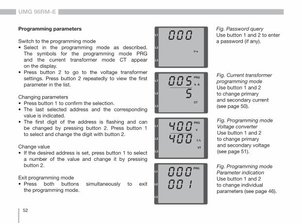
Fig. Password queryUse button 1 and 2 to enter a password (if any).
Fig. Current transformer programming modeUse button 1 and 2 to change primary and secondary current (see page 50).
Fig. Programming modeVoltage converterUse button 1 and 2 to change primary and secondary voltage (see page 51).
Programming parameters
Switch to the programming mode• Select in the programming mode as described.
The symbols for the programming mode PRG and the current transformer mode CT appear on the display.
• Press button 2 to go to the voltage transformer settings. Press button 2 repeatedly to view the first parameter in the list.
Changing parameters• Press button 1 to confirm the selection.• The last selected address and the corresponding
value is indicated.• The first digit of the address is flashing and can
be changed by pressing button 2. Press button 1 to select and change the digit with button 2.
Change value• If the desired address is set, press button 1 to select
a number of the value and change it by pressing button 2.
Exit programming mode• Press both buttons simultaneously to exit
the programming mode.
Fig. Programming modeParameter indicationUse button 1 and 2 to change individual parameters (see page 46).

53
UMG 96RM-E
TCP/IP configuration
Within an Ethernet, each device has a unique TCP / IP address that can be assigned manually or from a DHCP server. The 4-byte device address (0 to 3 byte) can be extended in the TCP / IP configuration using the subnet mask and gateway data.
Setting the TCP / IP device address (addr) manually• Select in the programming mode as described.
The symbols for the programming mode PRG and the current transformer mode CT appear on the display.
• Press button 2 three times to get to the TCP / IP settings for the device addressing.
• Press button 1 to select the desired digit. The selection is indicated by a flashing digit.
• Press button 2 to adjust the selected digit.• Use button 1 to select the next digit and set it again
by pressing button 2.
• If byte is set to 0, the TCP / IP address can be set from 1 to 3 by pressing button 1. Then the display jumps back to Byte 0 (no digit is flashing).
Description
Byte identification (e.g. byte 0) of the address
Address value, byte 0
Fig. TCP/IP address, byte 1A TCP / IP address consists of 4 bytes with the following structure:
xxx.xxx.xxx.xxx
Byte 1Byte 0 Byte 2 Byte 3
Fig. TCP / IP address, byte 2, value 003
Fig. TCP / IP address, byte 3, value 177
192.168.003.177Example:

54
UMG 96RM-E
Manual setting of the subnet mask (SUb)• When in the programming mode, press button 2 to get
to the subnet mask settings (SUb display).• Use button 1 to select the desired digit and set
it by pressing button 2. Repeat this step for each digit in bytes 0 to 3 in a way similar to setting the TCP / IP device address.
• After repeated display of byte 0 (no digit is flashing) one can set the gateway address.
Manual setting of the gateway address (GAt)• When in the programming mode, press button 2 to get
to the gateway address settings (GAt display).• Press buttons 1 and 2 to set the desired gateway
address in bytes 0 to 3 as described above.
Disable the dynamic IP allocation (dYN IP, oFF) to ensure that the manual settings of the TCP / IP device address, subnet mask and gateway address are not overwritten by a DHCP server.
Dynamic IP allocation (dyn)The dynamic allocation of the TCP / IP settings (device/gateway address and subnet mask) provides for a fully automated integration of the device into an existing network with a DHCP server. TCP / IP settings do not need to be configured manually as they are automatically assigned by the DHCP server when the device is started.
Addresses are read out in the programming mode the same way as in the manual settings.
• Switch to the programming mode as described. The symbols for the programming mode PRG and the current transformer mode CT appear on the display.
• Press button 2 several times to display the dynamic IP allocation (dYn IP).
• Press button 1 to enable the parameter "on" or "oFF" (parameter is flashing).
• Press button 2 to select the parameter and confirm by pressing button 1. Exit the programming mode or wait about 60 seconds.
C Changes will only take effect after you exit the programming mode.
If the key symbol is displayed, the dynamic IP allocation is enabled. Device / gateway address and subnet mask are provided and automatically accepted by the DHCP server.

55
UMG 96RM-E
Fig. Enabled dynamic allocation (dYn IP) of the TCP / IP address
Fig. Gateway (GAt), byte 0, value 192
Fig. Subnet mask (Sub), byte 0, value 255
Fig. Disabled dynamic allocation (dYn IP) of the TCP / IP address
m Caution! Connection of the UMG96RM-E to the Ethernet may only be carried out after discussion with the network administrator!
m Caution! The UMG 96RM-E is factory-programmed for the dynamic allocation of the IP settings (DHCP mode).Settings can be changed as described in TCP/IP Configuration or, for example, via an appropriate Ethernet connection by means of GridVis software.

56
UMG 96RM-E
RS485 device address (Addr. 000)
If multiple devices are connected to each other via the RS485 interface, a master device can only identify the devices by their device address. Within a network, each device must have its own device address. Addresses can be set in the range of 1 to 247.
C The adjustable range of the device address is between 0 and 255. Values 0 and 248 through 255 are reserved and may not be used.
Setting Baud rate
0 9.6kbps
1 19.2kbps
2 38.4kbps
3 57.6kbps
4 115.2kbps (factory setting)
RS485 baud rate (Addr. 001)
A common baud rate can be adjusted for the RS485 interfaces. The baud rate must be uniform for all devices on the network. Address 003 can be used to set the number of stop bits (0=1bit, 1= 2bits). Data bits (8) and parity (none) are fixed default values.

57
UMG 96RM-E
User password (Addr. 050)
A user password can be programmed to prevent accidental change of the programming data. Changes in the programming menu below can only be made after entering the correct user password. User password is not factory-programmed. In this case, the password menu is skipped and you get directly to the current transformer menu.
If a user password was programmed, the password menu appears on the display with the indication „000“. The first digit of the user password is flashing and can be changed by pressing button 2. Press button 1 to select the next digit while it is flashing.You can only get to the current transformer programming menu after entering the correct code.
Forgot my password
If you do not remember your password, you can only delete it using the GridVis PC software.In order to do so, connect the UMG96RM-E to the PC with a suitable interface. More information can be found in the GridVis assistant.
MODBUS gateway (Addr. 002)
Set address 002 as described in the table below to use the UMG 96RM-E Modbus Gateway function:
Setting Baud rate
0Modbus Gateway disabled (OFF)(Factory setting)
1 Modbus Gateway enabled (ON)

58
UMG 96RM-E
Averaging method
The applied exponential messaging method reaches at least 95% of the measurement value once the reporting time has run its course.
Min. and max. values
All measured values are measured and calculated during all 10/12 periods. Minimum and maximum values are determined for most measured values. The min. value is the smallest measured value determined since the last deletion. The max. value is the highest measured value determined since the last deletion. All minimum and maximum values are compared with the corresponding measured values and overwritten when exceeded or fallen short of.The minimum and maximum values are saved every 5 minutes in an EEPROM without date and time. Thus, the minimum and maximum values of the past 5 minutes may be lost due to an operating voltage failure.
Delete min. and max. values (Addr.506)
If „001“ is set for address 506, all minimum and maximum values can be deleted simultaneously.
Parameter
Mean value
Mean values are averaged over an adjustable period for the current, voltage and power measured values. The mean values are indicated by a bar over the measured value.The averaging time can be selected from a list with 9 fixed averaging times.
Averaging time, current (Addr. 040)Averaging time, power (Addr. 041)Averaging time, voltage (Addr. 042)
Setting Averaging time/sec.
0 51 102 153 304 605 3006 480 (factory setting)7 6008 900

59
UMG 96RM-E
Mains frequency (Addr. 034)
For automatic ascertainment of the mains frequency, an L1-N voltage larger than 10Veff must be applied to the voltage measurement input V1.
The sampling frequency is computed for the current and voltage inputs based on the mains frequency.
If the test voltage is missing, neither the network nor the sampling frequency can be computed. An acknowledgeable error message "500" will be displayed. Voltage, current and all resulting values are calculated and displayed based on the most recent frequency measurement and/or possible power couplings. The measured values that have been determined can no longer guarantee the declared precision.
When another measurement of frequency can be carried out, the error message will automatically disappear in about 5 seconds after the voltage returns.
The error is not displayed when a fixed frequency is set.
Setting range: 0, 45 .. 650 = automatic frequency determination.The mains frequency is determined based on the measurement voltage.45..65 = fixed frequencyThe mains frequency is pre-selected as a fixed value.

60
UMG 96RM-E
Energy meter
The UMG 96RM-E has power meters for active energy, reactive energy and apparent energy.
Active energy reading
Total active energy
The active energy given in this example is 12 345 678 kWh
The active energy given in this example is 134 178 kWh
Reset energy meter (Addr. 507)
The real, apparent and reactive energy meters can only be reset simultaneously.
Set "001" for address 507 to reset the energy meter.
If you reset the energy meter, the data will be lost. To avoid data loss, you should read and save the measured values before deletion using the GridVis software.
C

61
UMG 96RM-E
Harmonics
Harmonics are integer multiples of a fundamental oscillation. The fundamental oscillation of the voltage for UMG 96RM-E must range between 45 and 65Hz. The calculated harmonic voltages and currents relate to this fundamental oscillation. Harmonics up to 40 times the fundamental frequency are detected.
The harmonics of the currents and of the voltages are displayed in amperes and volts, respectively.
Fig. Indication of the 15th harmonics of the current in phase L3 (example).
Number of the harmonic component
Phase L3
Current harmonics
Value
C Harmonics are not displayed in the default factory setting.
Total harmonic distortion THD
THD is the ratio of the rms value of the harmonics to the rms value of the fundamental oscillation.
Phase L3
Voltage
Value
Fig. Indication of the total harmonic distortion THD of the voltage of phase L3 (example).
Total harmonic distortion of the current THDI:
Total harmonic distortion of the voltage THDU:
THDU
UUfund
n Harmn
M
==∑1 2
2.
THDI
IIfund
n Harmn
M
==∑1 2
2.
62
UMG 96RM-E
Measured value rotation
All 10/12 periods the measured values are calculated and the readings are displayed on a per second basis. There are two ways to retrieve the measurement readings:
• The automatically changing indication of the selected measurement readings is referred to herein as measured value rotation.
• Press button 1 and 2 to select measured value indication from a pre-selected display profile.
Both methods are available simultaneously. The measured value rotation is enabled when at least one measured value indication change time is over 0 seconds. Press a button to scroll the measured value indications of selected display profile. If no button is pressed for about 60 seconds, the device will switch to the measured value rotation to display the programmed measured value indications from the selected rotation profile in succession.
Rotation time (Addr. 039)
Setting range : 0 .. 60 secondsIf 0 seconds are set, the measured value indications selected will not be rotated.The rotation time set applies to all display rotation profiles.
Display rotation profile (Addr. 038)
Setting range: 0 .. 30 - Display rotation profile 1, pre-programmed.1 - Display rotation profile 2, pre-programmed.2 - Display rotation profile 3, pre-programmed.3 - Display rotation profile, customizable.
Measured value indocations
Following a power resumption, the UMG 96RM-E displays the first measurement value table in the current display profile. To keep the selection to a manageable size, only a fraction of the available measurement values was preprogrammed in the factory for retrieval in the measured value display. Select another display profile to view other measured values on the UMG 96RM-E display.

63
UMG 96RM-E
Display profile (Addr. 037)
Setting range: 0 .. 3 0 - Display profile 1, default value. 1 - Display profile 2, default value. 2 - Display profile 3, default value. 3 - Display profile, customizable.
C The customizable profiles (display rotation prof i le and display prof i le ) can only be programmed using the GridVis software.
C Profile settingBoth profi les (display rotation profi le and d isp lay p ro f i l e ) a re i l l us t ra ted in the GridVis software included in the delivery package. The profiles can be adjusted using the Device Configuration function of the software; customizable display profiles are programmed individually.A connection between the UMG 96RM-E and the PC via an interface is required for the use of the GridVis software Fig. Profile setting in the GridVis software.

64
UMG 96RM-E
Phase sequence
The voltage phase sequence and the phase L1 frequency are displayed on the screen. The phase sequence shows the three-phase system sequence. The rotary field usually rotates to the "right".The voltage measurement input phase sequence is checked and displayed in the UMG 96RM-E. If the string moves in a clockwise direction, this means that the rotary field rotates to the "right"; if the string moves in a counter-clockwise direction, this means that the rotary field rotates to the "left".The field rotation can only be determined when the measurement and operating voltage inputs are fully connected. If a phase is missing or two equal phases are connected, then the phase sequence is not determined and the string is not moving.
Fig. Indication of the supply frequency (50.0) and the phase sequence.
Fig. Rotary field direction can not be determined.
LCD contrast (Addr. 035)
The preferred view for the LCD display is from "below". The LCD display contrast can be adapted by the user. The contrast can be set stepwise in the range from 0 to 9.
0 = very bright 9 = very dark
Factory default setting: 5
Backlight
The LCD backlight allows the display to be read easily even in poor light. The brightness can be controlled by the user in stages from 0 to 9.
The UMG 96RM has two different types of backlight:
- the operation backlight- the standby backlight

65
UMG 96RM-E
Time recording
The UMG 96RM-E records the operating hours and the overall runtime of each comparator,
• where the operating period is measured and displayed in hours with a resolution of 0.1 h
• and the overall runtime of the comparators is displayed in seconds (when reaching 999999s is displayed in hours).
The periods are marked by the digits 1 to 6 for the measured value display enquiry:
keine = operating hours meter1 = Overall runtime, comparator 1A2 = Overall runtime, comparator 2A3 = Overall runtime, comparator 1B4 = Overall runtime, comparator 2B5 = Overall runtime, comparator 1C6 = Overall runtime, comparator 2C
In the measured value display, a maximum of 99999.9 h (= 11.4 years) can be displayed.
Operation backlight (addr. 036)The operation backlight is activated by pushing the appropriate button, or with a restart.
Standby backlight (addr. 747)This backlight is activated after an adjustable period of time (addr. 746). If no button is pressed within this period, then the device switches to the standby backlight.If buttons 1 - 3 are pressed, the device switches to the operation backlight and the defined period of time begins again.
If the brightness settings for the two backlights are set to the same value, then no change is discernible between the operation and standby backlights.
Addr. Description Setting range
Default setting
036 Brightness foroperation backlight
0 .. 9 6
746 Period of time after which the backlight will switch to standby
60 .. 9999 Sek.
900 Sek.
747 Brightness forstandby backlight
0 .. 9 0
0 = min. brightness, 9 = max. brightness

66
UMG 96RM-E
Fig. Measured value indications Operating hours meterThe UMG 96RM-E operating hours meter reading is 140.8h. This corresponds to 140 hours and 80 industrial minutes. 100 industrial minutes = 60 minutes. In this example, 80 industrial minutes = 48 minutes.
Operating hours meter
The operating hours meter measures the UMG 96RM-E recording and displaying time. The operating period is measured and displayed in hours with a resolution of 0.1 h. The operating hours meter cannot be reset.
Overall runtime of comparators
The overall runtime of a comparator is the sum of the runtimes exceeding the comparator result limit value. The total running time of the comparators can only be reset by the GridVis software. All running times are reset simultaneously.
Serial number (Addr. 754)
The serial number displayed by the UMG 96RM-E consists of 6 digits and is a part of the serial number given on the rating plate.The serial number cannot be changed.
Software release (Addr. 750)The UMG 96RM-E software is continuously improved and extended. The software status in the device is identified with a 3 digit number, the software release. The software release cannot be changed by the user.
Serial number
The serial number is on the rating plate: XX00-0000

67
UMG 96RM-E
Recordings
2 recordings are preconfigured in the default factory setting of the UMG 96RM-E. Recordings can be adjusted and extended via GridVis.
• The min. recording time base is 1 minute. • Maximum 4 recordings, each with 100 measured
values, are possible.
Recording 1:The following measured values are recorded with the time base of 15 minutes:• Effective voltage L1• Effective voltage L2• Effective voltage L3• Effective current L1• Effective current L2• Effective current L3• Effective current sum L1..L3• Effective power L1• Effective power L2• Effective power L3• Effective power sum L1..L3• Apparent power L1• Apparent power L2• Apparent power L3• Apparent power sum L1..L3
• cos phi(math.) L1• cos phi(math.) L2• cos phi(math.) L3• cos phi(math.) sum L1..L3• Reactive power fundamental oscillation harmonic L1• Reactive power fundamental oscillation harmonic L2• Reactive power fundamental oscillation harmonic L3• Reactive power fundamental oscillation harmonic
sum L1..L3
The mean value, minimum value and maximum value are also recorded for each measured value.
Recording 2:The following measured values are recorded with the time base of 1 hour:• Effective energy sum L1..L3• Inductive reactive energy sum L1..L3

68
UMG 96RM-E
Putting into service
Connecting the supply voltage
• The power supply voltage level for the UMG 96RM-E is given on the rating plate.
• After applying the power supply voltage the device switches on to display the first measured value.
• If no display appears, check whether the power supply voltage is within the rated voltage range.
Applying the measuring-circuit voltage
• Measurement of voltages in the mains with over 300VAC to earth must be connected via voltage transformers.
• After connecting the measurement-current voltages, the measured values displayed by the UMG 96RM-E for the L-N and L-L voltages must correspond to those at the voltage measurement input.
m Caution! Voltages and currents that are outside the permissible measuring range can lead to personal injury and damage the device.
m Caution! If the supply voltage does not correspond to the voltage indicated on the rating plate, this may lead to malfunctions severe damage to the device.
m Caution! The UMG 96RM is not suitable for measuring DC voltages.
Applying the measuring-circuit voltage
The UMG 96RM-E is designed for the connection of .. /1A and .. /5A current transformers.Only AC currents can be measured via the current measurement inputs - DC currents cannot.Short circuit all current transformer outputs except for one. Compare the currents displayed by the UMG 96RM with the applied current.Bearing in mind the current transformer conversion ratio, the current displayed by the UMG 96RM-E must correspond with the input current.The UMG 96RM-E must display approx. zero amperes in the short-circuited current measurement inputs.The current transformer ratio is factory set to 5/5A and must be adapted to the current transformer used if necessary.

69
UMG 96RM-E
Applying the residual current
Connect residual current transformer only to the I5 and I6 inputs with a rated current of 30mA! Both residual current inputs can measure AC currents, pulsing direct currents and DC currents.
Bearing in mind the current transformer conversion ratio, the residual current displayed by the UMG96RM-E must correspond with the input current.
The current transformer ratio is factory set to 5/5A and must be adapted to the residual current transformer used if necessary.
C It is not necessary to configure a connection schematic for residual current inputs I5 and I6.
Phase sequence
Check the direction of the voltage rotating field in the measured value display of the UMG 96RM-E. A “right” rotating field usually exists.
Check phase assignment
The assignment of the outer conductors to the current transformer is correct, if a current transformer is short circuited on the secondary, and the current indicated by the UMG 96RM-E drops to 0A in the corresponding phase.
Checking the energy measurement
Short-circuit all current transformer outputs except for one and check the displayed power outputs.The UMG 96RM-E may only display one power output in the phase with a non short-circuited current transformer input. If this is not the case, check the connection of the measuring-circuit voltage and the measuring-circuit current.
If the power output amount is correct but the sign of the power output is negative,• S1(k) and S2(l) could be inverted at the current
transformer • or they supply active energy back into the network.
C The UMG 96RM-E requires the mains frequency to measure the residual current. For this purpose, the measuring-circuit voltage should be applied or a fixed frequency should be set.

70
UMG 96RM-E
Checking the total power outputs
If all voltages, currents and outputs for the respective outer conductors are correctly displayed, the total power outputs measured by the UMG 96RM must also be correct. To confirm this, the total outputs measured by the UMG 96RM should be compared with the work of the active and reactive power meters located in the incoming supply.
Checking the measurement
If all voltage and current inputs are correctly connected, the individual and cumulative outputs are computed and displayed correctly.
Checking the individual outputs
In case that a current transformer is assigned to the wrong outer conductor, the corresponding power output will be measured and indicated incorrectly. The assignment of the outer conductor and the UMG 96RM-E current transformer is correct, if no voltage is measured between the outer conductor and the corresponding current transformer (primary).In order to ensure that an outer conductor at the voltage measurement input is assigned to the correct current transformer, the respective current transformer can be short-circuited on the secondary side. The apparent power displayed by the UMG 96RM-E must then be approx. zero in this phase.
If the apparent power is correctly displayed but the active power is displayed with a „-“ sign, then the current transformer terminals are reversed or power is supplied to the power supply company.

71
UMG 96RM-E
RS485 interface
The MODBUS RTU protocol with CRC check on the RS485 interface can be used to access the data from the parameter and the measured value lists.Address range: 1 .. 247Factory default setting: 1
The device is factory set to address 1 and the baud rate of 115,2 kbps.
Modbus functions (slave)04 Read input registers 06 Preset single register16 (10Hex) Preset multiple registers 23 (17Hex) Read/write 4X registers
The sequence of bytes is high before low byte (Motorola format).
Transmission parameters:Data bits: 8 Parity: no Stop bits (UMG 96RM): 2 External stop bits: 1 or 2
Number format: short 16 bit (-215 .. 215 -1. float 32 bit (IEEE 754)
The message length must not exceed 256 bytes.C
Broadcast (address 0) is not supported by the device.C

72
UMG 96RM-E
The Response of the UMG96 RM-E can appear as follows:
Description Hex NoteDevice address 01 UMG 96RM, address= 1Function 03Byte meter 06 Data 00 00hex = 00dezData E6 E6hex = 230dezError Check (CRC) -
The L1-N voltage read by address 19000 is 230V.
Example: Reading the L1-N voltageThe L1-N voltage is saved in the measured value list at address 19000. The L1-N voltage is available in the FLOAT format. Address = 01 is approved as the UMG 96RM-E device address.
The Query Message appears as follows:
Description Hex NoteDevice address 01 UMG 96RM, address= 1Function 03 „Read Holding Reg.“Start Addr. Hi 4A 19000dez = 4A38hexStart Addr. Lo 38Ind. Value Hi 00 2dez = 0002hexInd. Value Lo 02Error Check -

73
UMG 96RM-E
Digital outputs
The UMG 96RM-E features two digital outputs in group 1. Three further outputs can be used in group 2.
The User can allocate different functions to the digital outputs
The functions can be programmed by using the configuration menu of the GridVis software.
Fig.: Software GridVis, configuration menu
Fig.: Digital inputs of group 1 anddigital in- / outputs of group 2
Digital-Eingänge/Ausgänge
28 29 30 3113 14 15
24V DC
K1 K2
=-
+
K3 K4 K5
=-
+
=+
- S1 S2 S3
Gruppe 1 Gruppe 2
Digital inputs/outputs
Group 1 Group 2

74
UMG 96RM-E
Digital outputs - Status displays
The status of the switching outputs of group 1 is indicated by circular symbols in the display of the UMG 96RM-E.
Digital output stati
The current flow can be <1mA. Digital output 1: Addr. 608 = 0 Digital output 2: Addr. 609 = 0
The current flow can up to 50mA. Digital output 1: Addr. 608 = 1 Digital output 2: Addr. 609 = 1
Since the indication is updated once per second, faster status changes of the outputs can not be displayed.
C
Status digital output 1Status digital output 2
Group 1

75
UMG 96RM-E
Impulse output
The digital outputs can be used for the output of pulses for the computation of power consumption. For this purpose, a pulse of defined length is applied on the output after reaching a certain, adjustable amount of power.
You need to make various adjustments in the software GridVis (configuration menu) to use a digital output as a pulse one.
• Digital output,• Selection of source,• Selection of measured value,• Pulse length,• Pulse value.
Fig.: Software GridVis, configuration menu

76
UMG 96RM-E
Pulse length
The pulse length applies to both pulse outputs and is set by the software GridVis.
The typical pulse length of S0 pulse is 30ms.
Pulse intervalThe pulse interval is at least as large as the selected pulse length. The pulse interval depends on the measured power, for example, and can take hours or days.
Pulse length10ms .. 10s
Pulse interval>10ms
The values in the table are based on the minimum pulse length and the minimum pulse interval for the maximum number of pulses per hour.
Examples of the maximum possible number of pulses per hour.
Pulse length Pulse interval Max. pulse/h
10 ms 10 ms 180 000 pulse/h
30 ms 30 ms 60 000 pulse/h
50 ms 50 ms 36 000 pulse/h
100 ms 100 ms 18 000 pulse/h
500 ms 500 ms 3600 pulse/h
1 s 1 s 1800 pulse/h
10 s 10 s 180 pulse/h
Measured value selectionWhen programming with GridVis you have a selection of work values which are derived from the power output values.
CPulse intervalThe pulse interval is proportional to the power output within the selected settings.
C

77
UMG 96RM-E
Pulse value
The pulse value is used to indicate how much energy (Wh or varh) should correspond to a pulse.The pulse value is determined by the maximum connected load and the maximum number of pulses per hour.
If you check the pulse value with a positive sign, the pulses will only be emitted when the measured value has a positive sign.
If you check the pulse value with a negative sign, the pulses will only be produced when the measured value has a negative sign.
C Since the reactive energy meter operates with a backstop, pulses will only be generated with inductive load applied.
Since the active energy meter operates with a backstop, pulses will only be generated when drawing electricity.
C
Pulse value = max. connected load
max. number of pulses/h[Pulse/Wh]

78
UMG 96RM-E
Determine the pulse value
Set the pulse lengthSet the pulse length in accordance with the requirements of the connected pulse receiver.At a pulse length of 30 ms, for example, the UMG96RM generates a maximum number of 60,000 pulses (see Table "maximum number of pulses" per hour. Determining the maximum connected loadExample:
Current transformer = 150/5AVoltage L-N = max. 300 V
Power per phase = 150 A x 300 V = 45 kWPower at 3 phases = 45kW x 3Max. connected load = 135kW
Calculating the pulse value
Fig.: Connection example for the circuit as pulse output.
+ -
230V AC
24V DC
Externaloperating voltage
1.5k
Data logger
UMG 96RM-ESwitch and pulse outputs
+24V=
13
14
15
Pulse value = 135kW / 60,000 Imp/hPulse value = 0,00225 pulse/kWhPulse value = 2,25 pulse/Wh
Pulse value = max. connected load
max. number of pulses/h[Pulse/Wh]
C When using the digital outputs as pulse outputs the auxiliary voltage (DC) must have a max. residual ripple of 5%.

79
UMG 96RM-E
Comparators and monitoring threshold values
Five comparator groups (1-5) and 10 comparators per group (A – J) can be selected in order to monitor/control the thresholds. The results of the comparators A to J can be linked with AND or OR operators
The result of the AND and OR operator can be allocated to the respective digital output.
Fig.: Software GridVis, configuration menu

80
UMG 96RM-E
Service and maintenance
The device is subjected to several different safety tests before leaving the factory and is labelled with a seal. If a device is opened then the safety checks must be repeated. Warranty claims will only be accepted if the device is unopened.
Repair and calibration
Repair work and calibration can be carried out by the manufacturer only.
Front film
The front film can be cleaned with a soft cloth and standard household cleaning agent. Do not use acids and products containing acid for cleaning.
Disposal
The UMG 96RM can be reused or recycled as electronic scrap in accordance with the legal provisions. The permanently installed lithium battery must be disposed of separately.
Service
Should questions arise, which are not described in this manual, please contact the manufacturer directly.
We will need the following information from you to answer any questions:
- Device name (see rating plate),- Serial number (see rating plate),- Software release (see measured value display),- Measuring-circuit voltage and power supply voltage,- Precise description of the error.
Device calibration
The devices are calibrated by the manufacturer at the factory - it is not necessary to recalibrate the device providing that the environmental conditions are complied with.
Calibration intervals
It is recommended to have a new calibration carried out by the manufacturer or an accredited laboratory every 5 years approximately.

81
UMG 96RM-E
Battery
The internal clock is fed from the supply voltage. If the supply voltage fails then the clock is powered by the battery. The clock provides date and time information, for the records, min. and max. values and results, for example.
The life expectancy of the battery is at least 5 years with a storage temperature of +45°C. The typical life expectancy of the battery is 8 to 10 years.
The battery is replaced via the battery insert provided on the rear of the device. Make sure that the correct type of battery is used and correct polarity is observed when inserting the battery (positive pole faces the rear of the device; negative pole faces the front).
See chapter "Changing the battery" for more information.
Firmware update
If the device is connected to a computer via Ethernet, then the device firmware can be updated via the GridVis software.
Select a suitable update file (menu Extras / Update device) and the device and the new firmware will be transferred.
Fig. GridVis firmware update assistant
C Firmware may NOT be updated via the RS485 interface.

82
UMG 96RM-E
Status Status descriptionEEEbAt321
• Battery capacity is <85%• Operator confirmation required• Message appears weekly after
confirmation• Battery should be replaced
EEEbAt322
• Battery capacity is <75%• Battery capacity is too low• Can only be detected after resumption
of mains power• Battery should be replaced
EEEbAt330
• Battery capacity OK• Message can be acknowledged• Clock is stopped and must be set
EEEbAt331
• Battery capacity is <85%• Clock is stopped and must be set• Operator confirmation required• Message appears weekly after
confirmation• Battery should be replaced
EEEbAt332
• Battery capacity is <75%• Clock is stopped and must be set• Operator confirmation required• Message appears daily after confirmation• Battery should be replaced
Battery monitoring function
The device indicates the condition of the battery via the "EEE" symbol followed by "bAt" and the status number. Depending on the status number a confirmation of the information by the operator may be required. It is recommended that the battery be replaced.
Fault number
Battery fault status
Fault message symbol

83
UMG 96RM-E
Replacing the battery
If the battery capacity is shown as < 75 %, we recommend that the battery be replaced.
Procedure1. Disconnect system and device from power supply
before beginning work. 2. Discharge any electrostatic charge in your body,
e. g. by touching an earthed cabinet or metal part (radiator) connected to the earth of the building.
3. Remove the battery from the battery compartment, —e.g. using long-nose pliers—. The device does not need to be opened to do this as the battery compartment can be accessed from the outside (see figure on the right).
4. Make sure that the polarity is as shown on the insertion opening of the battery compartment and slide the replacement battery into the battery compartment. For this, use a battery compliant with the description in the technical data. The battery must fulfil the safety requirements of UL1642. Otherwise, there is a risk of combustion or explosion.
5. Dispose of the old battery according to the legal regulations.
6. Start up the system and the device again and check the functionality of the UMG 96-RM. Set the date and time.
c Dangerous voltage! Danger to life or risk of serious injury. Disconnect system and device from power supply before beginning work.
m Grease or dirt on the contact surfaces form a transfer resistance that will shorten the life of the battery. Only touch the battery at the edges.
Fig. Battery insertion on the rear
m Make sure that the correct type of battery is used and observe correct polarity when changing it.

84
UMG 96RM-E
Error/warning messages
The UMG 96RM-E can display four different error messages:
• warnings,• clock/battery errors,• fatal errors and• overranges.
In the case of warnings and fatal errors, the error message is followed by the "EEE" symbol and an error number.
The three-digit error number consists of the error description and - if set from the UMG 96RM - one or more error causes.
Errors Error descriptionEEE500
The mains frequency could not be determined. Possible causes:
The voltage at L1 is too small.The mains frequency does not range between 45 and 65Hz.
Remedy:Check the mains frequency.Select fixed frequency on the device.
Fig. Warning message with number 500 (mains frequency)
Symbol for a error message
Fault number
Fig. Error message
Warnings
Warnings are minor errors that can be acknowledged by buttons 1 or 2. The measured values continue to be retrieved and displayed. This error is displayed after each voltage return.

85
UMG 96RM-E
Clock/battery errors
Clock or battery errors are displayed together with the "EEE" symbol followed by "bAt" and a status number. For a more detailed description please refer to "Baterry control function" and "Replacing the battery".
Fig. Clock / battery error number 330 (clock does not run and has to be set.
Major errors
When a major error occurs, the device must be sent to the manufacturer's service center for inspection and adjustment.
Errors Error descriptionEEE910
Error while reading the calibration.
Errors Error description0x01 EEPROM does not respond.0x02 Address overrange.0x04 Checksum error.0x08 Error in the internal I2C bus.
Example, error message 911:
The error number consists of major error 910 and internal error cause 0x01 .
In this example an error occurred while reading the calibration data from EEPROM. The device has to be returned to the manufacturer for inspection and adjustment.
Internal causes: The UMG 96RM-E sometimes determines the cause of a major internal error with the following error code.

86
UMG 96RM-E
Overranges
Overranges are displayed as long as they exist and cannot be acknowledged. An overrange exists if at least one of the four voltage or current measurement inputs lies outside their specified measuring range.The "upwards" arrow indicates the phase where the overrrange occured. The appropriate error message for current path I4 is generated as shown below.The “V” and “A” symbols indicate whether the overrange occurred in the current or in the voltage path.
I = 7 AeffUL-N = 520 VL-N
Overrange limits:
A = current pathV = voltage path
Indication of the phase (L1/L2/L3) with overrange. The current phase l4 overranges occur as shown in the figure below.
Examples
A = current path
Fig.: Indication of the overrange in the current path of phase 2 (l2).
Fig.: Indication of the overrange in voltage path L3.
V = voltage path
Fig.: Indication of the overrange in current path l4

87
UMG 96RM-E
Parameter overrange
A detailed description of the error is coded in the parameter overrange (Addr. 600) in the following format:
Example: Error in phase 2 in the current path:
0xF2FFFFFF
Example: Error in phase 3 in the current path UL-N:
0xFFF4FFFF
F F F F F F F F
Phase 1:
Phase 2:
Phase 3:
Phase 4 (I4):
1
2
4
8
Cur
rent
:
1
2
4
8
U L
-N
0x

88
UMG 96RM-E
Procedure in the event of faults
Possible fault Cause Remedy
No display External fusing for the power supply voltage has tripped.
Replace fuse.
No current display Measurement voltage is not connected. Connect the measuring-circuit voltage.
Measurement current is not connected. Connect measuring-circuit current.
Current displayed is too large or too small.
Current measurement in the wrong phase. Check connection and correct if necessary.
Current transformer factor is incorrectly programmed.
Read out and program the current transformer transformation ratio at the current transformer.
The current peak value at the measurement input was exceeded by harmonic components.
Install current transformer with a larger transformation ratio.
The current at the measurement input fell short of.
Install current transformer with a suitable transformation ratio.
Voltage displayed is too large or too small.
Measurement in the wrong phase. Check connection and correct if necessary.
Voltage transformer incorrectly programmed. Read out and program the voltage transformer transformation ratio at the voltage transformer.
Voltage displayed is too small. Overrange. Install voltage transformers.
The peak voltage value at the measurement input has been exceeded by harmonic components.
Caution! Ensure the measurement inputs are not overloaded.
Phase shift ind/cap. A current path is assigned to the wrong voltage path.
Check connection and correct if necessary.
Effective power, consumption/supply reversed.
At least one current transformer connection is mixed up/reversed.
Check connection and correct if necessary.
A current path is assigned to the wrong voltage path.
Check connection and correct if necessary.

89
UMG 96RM-E
Possible fault Cause Remedy
Effective power too large or too small.
The programmed current transformer transformation ratio is incorrect.
Read out and program the current transformer transformation ratio at the current transformer
The current path is assigned to the wrong voltage path.
Check connection and correct if necessary.
The programmed voltage transformer transformation ratio is incorrect.
Read out and program the voltage transformer transformation ratio at the voltage transformer.
An output is not responding. The output was incorrectly programmed. Check the settings and correct if necessary.
The output was incorrectly connected. Check connection and correct if necessary.
"EEE" in the display See error messages.
"EEE bAt" in the display Battery capacity is too low See "Battery control function" and "Replacing the battery"
No connection with the device. RS485- Device address is incorrect.- Different bus speeds
(Baud rate).- Wrong protocol.- Termination missing.
- Adjust the device address.- Adjust speed (baud rate).
- Select the correct protocol.- Close bus with termination resistor.
Ethernet- IP address is incorrect.- Incorrect addressing mode
- Adjust IP address at the device.- Adjust the IP address assignment mode
Device still does not work despite the above measures.
Device defective. Send the device to the manufacturer for inspection and testing along with an accurate fault description.

90
UMG 96RM-E
Technical data
General information
Net weight (with attached connectors) approx. 370g
Packaging weight (including accessories) approx. 950g
Battery Lithium battery CR2032, 3V (approval i.a.w. UL 1642)
Service life of background lighting 40000h (after this period of time the background lighting efficiency will reduce by approx. 50 %)
Transport and storageThe following information applies to devices which are transported or stored in the original packaging.
Free fall 1m
Temperature K55 (-25°C to +70°C)
Relative humidity 0 to 90 % RH

91
UMG 96RM-E
Power supply voltage
Installations of overvoltage category 300V CAT II
Protection of the supply voltage (fusing) 6A, type C (approved i.a.w. UL/IEC)
Nominal range 20V - 250V (45..65Hz) or DC 20V - 300V
Operating range +-10% of nominal range
Power consumption max. 13VA / 5W
Ambient conditions during operation
The UMG 96RM is intended for weather-protected, stationary use.Protection class II i.a.w. IEC 60536 (VDE 0106, Part 1).
Operating temperature range K55 (-10°C .. +55°C)
Relative humidity 0 to 75 % RH
Operating altitude 0 .. 2000m above sea level
Degree of pollution 2
Mounting position vertical
Ventilation Forced ventilation is not required.
Protection against ingress of solid foreign bodies and water- Front side- Rear side- Front with seal
IP40 i.a.w. EN60529IP20 i.a.w. EN60529IP42 i.a.w. EN60529

92
UMG 96RM-E
Digital inputs3 optional digital outputs, semiconductor relays, not short-circuit proof.
Maximum counter frequency 20Hz
Input signal present 18V .. 28V DC (typical 4mA)
Input signal not present 0 .. 5V DC, current less than 0.5A
Digital outputs2 and 3 optional digital outputs, semiconductor relays, not short-circuit proof.
Switching voltage max. 33V AC, 60V DC
Switching current max. 50mAeff AC/DC
Response time 10/12 periods + 10ms *
Pulse output (energy pulse) max. 50Hz
* Response time e.g. at 50Hz: 200ms + 10ms = 210 ms

93
UMG 96RM-E
Temperature measurement input2 optional inputs.
Update time 1 second
Connectable sensors PT100, PT1000, KTY83, KTY84
Total burden (sensor + cable) max. 4 kOhm
Cable length (digital inputs and outputs, temperature measurement input)
Up to 30m Unshielded
More than 30m Shielded
Sensor type Temperature range Resistor range Uncertainty in measurement
KTY83 -55°C ... +175°C 500Ohm ... 2,6kOhm ± 1,5% rng
KTY84 -40°C ... +300°C 350Ohm ... 2,6kOhm ± 1,5% rng
PT100 -99°C ... +500°C 60Ohm ... 180Ohm ± 1,5% rng
PT1000 -99°C ... +500°C 600Ohm ... 1,8kOhm ± 1,5% rng

94
UMG 96RM-E
Serial interface
RS485 - Modbus RTU/Slave 9.6kbps, 19.2kbps, 38.4kbps, 57.6 kbps, 115.2kbps
Stripping length 7mm
Measuring voltage
Three-phase 4-conductor systems with nominal voltages up to 277V/480V (+-10%)
Three-phase 3-conductor systems, unearthed, with nominal voltages up to
IT 480V (+-10%)
Overvoltage category 300V CAT III
Measurement surge voltage 4kV
Measurement range L-N 01) .. 300Vrms(max. surge voltage 520Vrms )
Measurement range L-L 01) .. 520Vrms(max. surge voltage 900Vrms )
Resolution 0.01V
Crest factor 2,45 (related to the measurement range)
Impedance 4MOhm/phase
Power consumption apporx. 0,1VA
Sampling frequency 21.33kHz (50Hz); 25.6 kHz (60Hz) per measurement channel
Frequency range of the basic oscillation- Resolution
45Hz .. 65Hz0.01Hz
1) The UMG 96RM-E can only determine values, if a voltage L-N greater than 10Veff or a voltage L-L of greater than 18Veff is present at at least one voltage measurement input.

95
UMG 96RM-E
Current measurement I1 - I4
Rated current 5A
Measurement range 0 .. 6Arms
Crest factor 1.98
Resolution 0.1mA (Display 0.01A)
Overvoltage category 300V CAT II
Measurement surge voltage 2kV
Power consumption approx. 0.2 VA (Ri=5mOhm)
Overload for 1 sec. 120A (sinusoidal)
Sampling frequency 20kHz
Residual current measurement I5 / I6
Rated current 30mArms
Rated current 40mArms
Operating current 50µA
Resolution 1µA
Crest factor 1.414 (related to 40mA)
Burden 4 Ohm
Overload for 1 sec. 5A
Sustained overload 1A
Overload for 20 ms 50A
Residual current measurement i.a.w. IEC/TR 60755 (2008-01), Type A
Type B

96
UMG 96RM-E
Terminal connection capacity (power supply voltage)Conductors to be connected. Only one conductor can be connected per terminal!
Single core, multi-core, fine-stranded 0.2 - 2.5mm2, AWG 26 - 12
Terminal pins, core end sheath 0.2 - 2.5mm2
Tightening torque 0.4 - 0.5Nm
Stripping length 7mm
Ethernet connection
Connection RJ45
Functions Modbus gateway, embedded web server (HTTP)
Protocols TCP/IP, DHCP-Client (BootP), Modbus/TCP (Port 502),ICMP (Ping), NTP, Modbus RTU over Ethernet (Port 8000),FTP, SNMP
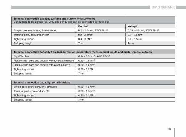
97
UMG 96RM-E
Terminal connection capacity (residual current or temperature measurement inputs and digital inputs / outputs)
Rigid/flexible 0.14 - 1.5mm2, AWG 28-16
Flexible with core end sheath without plastic sleeve 0.20 - 1.5mm2
Flexible with core end sheath with plastic sleeve 0.20 - 1.5mm2
Tightening torque 0.20 - 0.25Nm
Stripping length 7mm
Terminal connection capacity: serial interface
Single core, multi-core, fine-stranded 0.20 - 1.5mm2
Terminal pins, core end sheath 0.20 - 1.5mm2
Tightening torque 0.20 - 0.25Nm
Stripping length 7mm
Terminal connection capacity (voltage and current measurement)Conductors to be connected. Only one conductor can be connected per terminal!
Current Voltage
Single core, multi-core, fine-stranded 0.2 - 2.5mm2, AWG 26-12 0.08 - 4.0mm2, AWG 28-12
Terminal pins, core end sheath 0.2 - 2.5mm2 0.2 - 2.5mm2
Tightening torque 0.4 - 0.5Nm 0.4 - 0.5Nm
Stripping length 7mm 7mm

98
UMG 96RM-E
Function parameters
Function Symbol Precision class Measurement range Display range
Total effective power P 0.55) (IEC61557-12) 0 .. 5.4 kW 0 W .. 999 GW *
Total reactive power QA, Qv 1 (IEC61557-12) 0 .. 5.4 kvar 0 varh .. 999 Gvar *
Total apparent power SA, Sv 0.55) (IEC61557-12) 0 .. 5.4 kVA 0 VA .. 999 GVA *
Total active energy Ea 0.55) (IEC61557-12) 0 .. 5.4 kWh 0 Wh .. 999 GWh *
Total reactive power ErA, ErV 1 (IEC61557-12) 0 .. 5.4 kvarh 0 varh .. 999 Gvarh *
Total apparent energy EapA, EapV 0.55) (IEC61557-12) 0 .. 5.4 kVAh 0 VAh .. 999 GVAh *
Frequency f 0.05 (IEC61557-12) 45 .. 65Hz 45.00Hz .. 65.00Hz
Phase current I1 - I3 I 0.5 (IEC61557-12) 0 .. 6 Arms 0 A .. 999 kA
Measured neutral conductor current l4 IN 1 (IEC61557-12) 0 .. 6 Arms 0 A .. 999 kA
Residual currents I5, I6 IRes 1 (IEC61557-12) 0 .. 30 mArms 0 A .. 999 kA
Computed neutral conductor current INc 1.0 (IEC61557-12) 0.03 .. 25 A 0.03 A .. 999 kA
Voltage U L-N 0.2 (IEC61557-12) 10 .. 300 Vrms 0 V .. 999 kV
Voltage U L-L 0.2 (IEC61557-12) 18 .. 520 Vrms 0 V .. 999 kV
Power factor PFA, PFV 0.5 (IEC61557-12) 0.00 .. 1.00 0.00 .. 1.00
Short-term flicker, long-term flicker Pst, Plt - - -
Voltage drops (L-N) Udip - - -
Voltage increases (L-N) Uswl - - -
Transient overvoltages Utr - - -
Voltage drops Unit - - -
Voltage unbalance (L-N) 1) Unba - - -
Voltage unbalance (L-N) 2) Unb - - -
Voltage harmonics Uh Kl. 1 (IEC61000-4-7) up to 2.5 kHz 0 V .. 999 kV
THD of the voltage 3) THDu 1.0 (IEC61557-12) up to 2.5 kHz 0 % .. 999 %
THD of the voltage 4) THD-Ru - - -

99
UMG 96RM-E
Function Symbol Precision class Measurement range Display range
Current harmonics Ih Kl. 1 (IEC61000-4-7) up to 2.5 kHz 0 A .. 999 kA
THD of the current 3) THDi 1.0 (IEC61557-12) up to 2.5 kHz 0 % .. 999 %
THD of the current 4) THD-Ri - - -
Mains signal voltage MSV - - -
1) Referred to amplitude.2) Referred to phase and amplitude. 3) Referred to mains frequency.
4) Referred to root mean square value.5) Accuracy class 0.5 with ../5 A transformer. Accuracy class 1 with ../1 A transformer.
* The display returns to 0 W when the maximum total energy values are reached.

100
UMG 96RM-E
Table 1 – Parameter list
0 SHORT RD/WR - Device address 0..255 (*1) 1 1 SHORT RD/WR kbps Baud rate (0=9.6kbps, 1=19.2kbps, 0..7 4 2=38.4kbps, 3= 57.6kbps (5..7 only for 4=115.2kbps) internal use) 2 SHORT RD/WR - Modbus Master 0, 1 0 0=Slave, 1=Master (if Ethernet is provided) 3 SHORT RD/WR - Stop bits (0=1Bit, 1=2Bits) 0, 1 0 10 FLOAT RD/WR A Current transformer I1, primary 0..1000000 (*2) 5 12 FLOAT RD/WR A Current transformer l1, sec. 1..5 5 14 FLOAT RD/WR V Voltage transformer V1, prim. 0..1000000 (*2) 400 16 FLOAT RD/WR V Voltage transformer V1, sec. 100, 400 400 18 FLOAT RD/WR A Current transformer I2, primary 0..1000000 (*2) 5
Address format RD/WR Unit Note Adjustment range Default
Parameter and modbus address list
The following excerpt of the parameter list provides the settings that are necessary for the proper operation of the UMG 96RM-E, such as current transformer and device addresses. The values in the parameter list can be set and read.
The excerpt of the measured value list includes the measured and calculated values, output status data and recorded values to be read.
C A complete overview of the parameters and measured values as well as explanations regarding the selected measured values is filed in the document “Modbus Address List” on the CD or Internet.
C The addresses contained in the description can be adjusted directly on the device in the range from 0 to 800. The address range above 1000 can only be processed via modbus!
(*1) Values 0 and 248 through 255 are reserved and may not be used.
(*2) The adjustable value of 0 does not produce any useful work values and must not be used.

101
UMG 96RM-E
20 FLOAT RD/WR A Current transformer I2, sec. 1..5 5 22 FLOAT RD/WR V Voltage transformer V2, prim. 0..1000000 400 24 FLOAT RD/WR V Voltage transformer V2, sec. 100, 400 400 26 FLOAT RD/WR A Current transformer I3, primary 0..1000000 5 28 FLOAT RD/WR A Current transformer I3, sec. 1..5 5 30 FLOAT RD/WR V Voltage transformer V3, prim. 0..1000000 400 32 FLOAT RD/WR V Voltage transformer V3, sec. 100, 400 400 34 SHORT RD/WR Hz Frequency estimation 0, 45 .. 65 0 0=Auto, 45 .. 65=Hz 35 SHORT RD/WR - Display contrast 0 .. 9 5 0 (low), 9 (high) 36 SHORT RD/WR - Background lighting 0 .. 9 6 0 (dark), 9 (bright) 37 SHORT RD/WR - Display profile 0 .. 3 0 0=preset display profile 1=preset display profile 2=preset display profile 3=customizable display profile 38 SHORT RD/WR - Display rotation profile 0 .. 3 0 0..2=preset display rotation profile 3=customizable display rotation profile 39 SHORT RD/WR s Rotation time 0 .. 60 0 40 SHORT RD/WR - Reporting time, I 0 .. 8* 6 41 SHORT RD/WR - Reporting time, P 0 .. 8* 6 42 SHORT RD/WR - Reporting time, U 0 .. 8* 6 45 USHORT RD/WR mA Response threshold of 0 .. 50 5 current measuring I1 .. I3
Address format RD/WR Unit Note Adjustment range Default
* 0 = 5sec.; 1 = 10sec.; 2 = 15sec.; 3 = 30sec.; 4 = 1min.; 5 = 5min.; 6 = 8min.; 7 = 10min.; 8 = 15min.

102
UMG 96RM-E
Address format RD/WR Unit Note Adjustment range Default
50 SHORT RD/WR - Password 0 .. 999 0 (No password)
100 SHORT RD/WR - Measured value address, Digital output 1 0..32000 0 101 SHORT RD/WR - Measured value address, Digital output 2 0..32000 0 102 FLOAT RD/WR Wh Pulse value, Digital output 1 -1000000..+1000000 0 104 FLOAT RD/WR Wh Pulse value, Digital output 2 -1000000..+1000000 0 106 SHORT RD/WR 10ms Min. pulse length (1=10ms) Digital output 1/2 1..1000 5 (=50ms)
500 SHORT RD/WR - Connector pin assignment, I L1 -3..0..+3 +1 501 SHORT RD/WR - Connector pin assignment, I L2 -3..0..+3 +2 502 SHORT RD/WR - Connector pin assignment, I L3 -3..0..+3 +3 503 SHORT RD/WR - Connector pin assignment, U L1 0..3 1 504 SHORT RD/WR - Connector pin assignment, U L2 0..3 2 505 SHORT RD/WR - Connector pin assignment, U L3 0..3 3 506 SHORT RD/WR - Min- und Reset max. values 0..1 0 507 SHORT RD/WR - Reset energy meter 0..1 0 508 SHORT RD/WR - force EEPROM descr. 0..1 0
Note: Energy values and min-max values are recorded into the EEPROM every 5 minutes.
509 SHORT RD/WR - Voltage connection diagram 0..7 0 510 SHORT RD/WR - Current connection diagram 0..8 0 511 SHORT RD/WR - Relevant voltage for THD and FFT 0, 1 0
The THD and FFT voltages can be displayed as L-N or L-L values. 0=LN, 1=LL

103
UMG 96RM-E
C Only the first 3 digits (###) of a value are displayed on the screen. Values greater than 1000 are marked with "k". Example: 003k = 3000
512 SHORT RD/WR - Year 0..99 *2 513 SHORT RD/WR - Month 0..12 *2 514 SHORT RD/WR - Day 0..31 *2 515 SHORT RD/WR - Hour 0..24 *2 516 SHORT RD/WR - Minute 0..59 *2 517 SHORT RD/WR - Second 0..59 *2
600 UINT RD/WR - Overrange 0..0xFFFFFFFF 750 SHORT RD - Software release 754 SERNR RD - Serial number 756 SERNR RD - Production no.
746 SHORT RD/WR s Period of time after which the backlight will switch to standby 60 .. 9999 900 747 SHORT RD/WR s Brightness of the standby backlight 0 .. 9 0
Address format RD/WR Unit Note Adjustment range Default
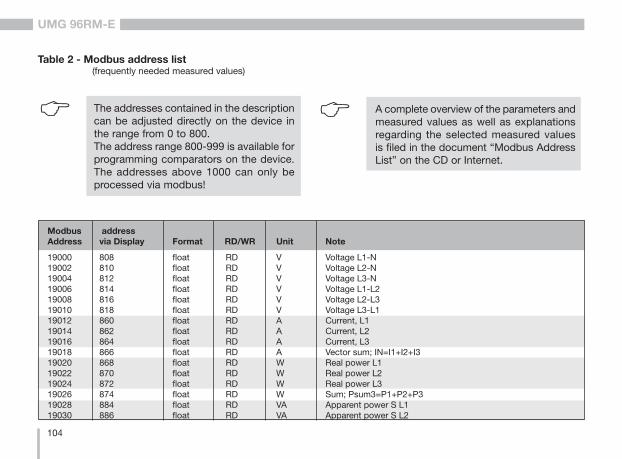
104
UMG 96RM-E
Table 2 - Modbus address list (frequently needed measured values)
19000 808 float RD V Voltage L1-N19002 810 float RD V Voltage L2-N19004 812 float RD V Voltage L3-N19006 814 float RD V Voltage L1-L219008 816 float RD V Voltage L2-L319010 818 float RD V Voltage L3-L119012 860 float RD A Current, L119014 862 float RD A Current, L219016 864 float RD A Current, L319018 866 float RD A Vector sum; IN=I1+I2+I319020 868 float RD W Real power L119022 870 float RD W Real power L219024 872 float RD W Real power L319026 874 float RD W Sum; Psum3=P1+P2+P319028 884 float RD VA Apparent power S L119030 886 float RD VA Apparent power S L2
Modbus address Address via Display Format RD/WR Unit Note
C The addresses contained in the description can be adjusted directly on the device in the range from 0 to 800. The address range 800-999 is available for programming comparators on the device. The addresses above 1000 can only be processed via modbus!
C A complete overview of the parameters and measured values as well as explanations regarding the selected measured values is filed in the document “Modbus Address List” on the CD or Internet.

105
UMG 96RM-E
19032 888 float RD VA Apparent power S L319034 890 float RD VA Sum; Ssum3=S1+S2+S319036 876 float RD var Fund. reactive power (mains frequ.) Q L119038 878 float RD var Fund. reactive power (mains frequ.) Q L219040 880 float RD var Fund. reactive power (mains frequ.) Q L319042 882 float RD var Sum; Qsum3=Q1+Q2+Q319044 820 float RD - Fund.power factor, CosPhi; U L1-N IL119046 822 float RD - Fund.power factor, CosPhi; U L2-N IL219048 824 float RD - Fund.power factor, CosPhi; U L3-N IL319050 800 float RD Hz Measured frequency19052 - float RD - Rotation field; 1=right, 0=none, -1=left19054 - float RD Wh Real energy L119056 - float RD Wh Real energy L219058 - float RD Wh Real energy L319060 - float RD Wh Real energy L1..L319062 - float RD Wh Real energy L1, consumed19064 - float RD Wh Real energy L2, consumed19066 - float RD Wh Real energy L3, consumed19068 - float RD Wh Real energy L1..L3, consumed, rate 119070 - float RD Wh Real energy L1, delivered19072 - float RD Wh Real energy L2, delivered19074 - float RD Wh Real energy L3, delivered19076 - float RD Wh Real energy L1..L3, delivered19078 - float RD VAh Apparent energy L119080 - float RD VAh Apparent energy L219082 - float RD VAh Apparent energy L319084 - float RD VAh Apparent energy L1..L319086 - float RD varh Reactive energy L119088 - float RD varh Reactive energy L219090 - float RD varh Reactive energy L319092 - float RD varh Reactive energy L1..L3
Modbus Address address via Display Format RD/WR Unit Note

106
UMG 96RM-E
19094 - float RD varh Reactive energy, inductive, L119096 - float RD varh Reactive energy, inductive, L219098 - float RD varh Reactive energy, inductive, L319100 - float RD varh Reactive energy L1..L3, ind.19102 - float RD varh Reactive energy, capacitive, L119104 - float RD varh Reactive energy, capacitive, L219106 - float RD varh Reactive energy, capacitive, L319108 - float RD varh Reactive energy L1..L3, cap.19110 836 float RD % Harmonic, THD, U L1-N19112 838 float RD % Harmonic, THD, U L2-N19114 840 float RD % Harmonic, THD, U L3-N19116 908 float RD % Harmonic, THD, I L119118 910 float RD % Harmonic, THD, I L219120 912 float RD % Harmonic, THD, I L3
Modbus Address address via Display Format RD/WR Unit Note
20006 - float RD/WR A TDD I4, full-load current 0...1000000 15020008 - float RD/WR A current transformer I4, primary 0...1000000 520010 - float RD/WR A current transformer I4, secondary 1..5 520012 - float RD/WR A current transformer I5, primary 0..1000000 520014 - float RD/WR A current transformer I5, secondary 0,001...5 520016 - float RD/WR A current transformer I6, primary 0...1000000 520018 - float RD/WR A current transformer I6, secondary 0,001...5 5
Modbus Address address via display Format RD/WR Unit Note Adjustment range Default

107
UMG 96RM-E
Type Size Minimum Maximum
short 16 bit -215 215 -1
ushort 16 bit 0 216 -1
int 32 bit -231 231 -1
uint 32 bit 0 232 -1
float 32 bit IEEE 754 IEEE 754
Number formats
C Notes on saving measurement values and configuration data:
• The following measurement values are saved at least every 5 minutes:• Comparator timer• S0 meter readings• Minimum / maximum / mean values• Energy values
• Configuration data is saved immediately!

108
UMG 96RM-E
Dimension diagrams
All dimensions provided in mm
Rear view View from below
110,5
91,5

109
UMG 96RM-E
Side view
ca. 90 72
96
6 57 78
91,5
100
(depth without connector)
92+0
,8
92+0,8
Cut-out size

110
UMG 96RM-E
Measured value displays overview
Measured valuesL1-N voltage L2-N voltageL3-N voltage
A01
Measured values L1-L2 voltage L2-L3 voltage L3-L1 voltage
A02
Measured values L1 current L2 current L3 current
A03
Measured value Sum
Current in N
A04
Mean valuesL1-N voltage L2-N voltageL3-N voltage
B01
Mean values L1-L2 voltage L2-L3 voltage L3-L1 voltage
B02
Mean values L1 currentL2 currentL3 current
B03
Mean value Sum
Current in N
B04
Max. valuesL1-N voltageL2-N voltageL3-N voltage
C01
Max. valuesL1-L2 voltageL2-L3 voltageL3-L1 voltage
C02
Max. valuesL1 currentL2 currentL3 current
C03
Max. value Max. value sum
Current in N
C04
Min. valueL1-N voltageL2-N voltageL3-N voltage
D01
Min. valueL1-L2 voltageL2-L3 voltageL3-L1 voltage
D02
Max. values (mean values)L1 currentL2 currentL3 current
D03
Max. valuesMean value sum
Current in N
D04
Measured values L1 effective powerL2 effective powerL3 effective power
A05
Measured value Sum
Effective power
A06
Mean valueL1 effective powerL2 effective powerL3 effective power
B05
Mean value Sum
Effective power
B06
Max. values L1 effective powerL2 effective powerL3 effective power
C05
Max. value Sum
Effective power
C06
Max. valueSum
Effective power mean value
D06
Measured valuesL1 apparent powerL2 apparent powerL3 apparent power
A07
Mean valuesL1 apparent powerL2 apparent powerL3 apparent power
B07
Max. valuesL1 apparent powerL2 apparent powerL3 apparent power
C07

111
UMG 96RM-E
Measured valueTotal Harmonic Distortion
(THD)I L1
A12
Measured valueTotal Harmonic Distortion
(THD)I L2
B12
Measured valueTotal Harmonic Distortion
(THD)I L3
C12
Max. valueTotal Harmonic Distortion
(THD)U L1
A13
Max. valueTotal Harmonic Distortion
(THD)I L1
A14
Max. valueTotal Harmonic Distortion
(THD)U L2
B13
Max. valueTotal Harmonic Distortion
(THD)I L2
B14
Max. valueTotal Harmonic Distortion
(THD)U L3
C13
Max. valueTotal Harmonic Distortion
(THD)I L3
C14
Measured value Sum
Apparent power
A08
Measured values L1 reactive power L2 reactive power L3 reactive power
A09
Measured valueReactive power sum
A10
Measured valueTotal Harmonic Distortion
(THD)U L1
A11
Mean value Sum
Apparent power
B08
Mean valuesL1 reactive powerL2 reactive powerL3 reactive power
B09
Mean valueReactive power sum
B10
Measured valueTotal Harmonic Distortion
(THD)U L2
B11
Max. value Sum
Apparent power
C08
Max. values (ind) L1 reactive powerL2 reactive powerL3 reactive power
C09
Max. value (ind)Reactive power sum
C10
Measured valueTotal Harmonic Distortion
(THD)U L3
C11

112
UMG 96RM-E
Measured value L1 cos(phi) L2 cos(phi) L3 cos(phi)
A15
Measured value Sum cos(phi)
A16
Measured value Frequency L1
Rotary field indication
A17
Measured value Total active energy(without backstop)
A18
Mean value Sum cos(phi)
B16
Measured valueTotal active energy
(Consumption)
B18
Measured valueTotal active energy
(Supply)
C18
Measured valueSum
Apparent energy
D18
Measured value (ind)Reactive power
A19
Operating hoursmeter 1
A20
Measured value1. Harmonics
U L1
A21
Measured value Sum
Reactive powercap.
B19
Comparator 1A*Overall runtime
B20
Measured value3. Harmon.
U L1
B21
Measured value Sum
Reactive powercap.
C19
...
...
Comparator 2C*Overall runtime
G20
Measured value15. Harmon.
U L1
H21
Highlighted menus are not displayed with the factory presets. * Only the first 6 comparators are shown.

113
UMG 96RM-E
Measured value1. Harmonics
I L3
A26
Max. value1. Harmonics
U L1
A27
Max. value1. Harmonics
U L2
A28
Measured value3. Harmon.
I L3
B26
Max. value3. Harmonics
U L1
B27
Max. value3. Harmonics
U L2
B28
...
...
...
Measured value15. Harmon.
I L3
H26
Max. value15. Harmonics
U L1
H27
Max. value15. Harmonics
U L2
H28
Highlighted menus are not displayed with the factory presets.
Measured value1. Harmonics
U L2
A22
Measured value1. Harmonics
U L3
A23
Measured value1. Harmonics
I L1
A24
Measured value3. Harmon.
U L2
B22
Measured value3. Harmon.
U L3
B23
Measured value3. Harmon.
I L1
B24
...
...
...
Measured value15. Harmon.
U L2
H22
Measured value15. Harmon.
I L1
H24
Measured value15. Harmon.
U L3
H23
Measured value1. Harmonics
I L2
A25
Measured value3. Harmon.
I L2
B25
...Measured value
15. Harmon.I L2
H25

114
UMG 96RM-E
Max. value1. Harmonics
U L3
A29
Max. value1. Harmonics
I L1
A30
Max. value3. Harmonics
U L3
B29
Max. value3. Harmonics
I L1
B30
...
...Max. value
15. HarmonicsI L1
H30
Max. value15. Harmonics
U L3
H29
Max. value1. Harmonics
I L2
A31
Max. value1. Harmonics
I L3
A32
Max. value3. Harmonics
I L2
B31
Max. value3. Harmonics
I L3
B32
...
...Max. value
15. HarmonicsI L3
H32
Max. value15. Harmonics
I L2
H31
Highlighted menus are not displayed with the factory presets.
Direct and indirect harmonics up to 40 can be called up and viewed via the GridVis software.
Measured value L4 Strom
A33
Measured value L5 current
A34
Measured value L6 current
A35
Mean valueL4 Strom
B33
Mean valueL5 current
B34
Mean valueL6 current
B35
Max. valuesL4 Strom
C33
Max. valuesL5 current
C34
Max. valuesL6 current
C35
Max. values (mean values)
L4 Strom
D33
Max. values (mean values)
L5 current
D34
Max. values (mean values)L6 current
D35

115
UMG 96RM-E

116
UMG 96RM-E
Declaration of conformity
The product fulfils the following EC Directives:
2004/108/EG Electromagnetic compatibility of electrical equipment.
2006/95/EG Electrical equipment for use within certain voltage limits.
Considered standards:
Noise immunityIEC/EN 61326-1:2013 Class A: Industrial environmentIEC/EN 61000-4-2:2009 Electrostatic dischargeIEC/EN 61000-4-3:2011 Electromagnetic RF Field 80-2700MHzIEC/EN 61000-4-4:2013 BurstIEC/EN 61000-4-5:2007 Surge IEC/EN 61000-4-6:2009 Conducted disturbances 0,15-80MHzIEC/EN 61000-4-8:2010 Power frequency magnetic field IEC/EN 61000-4-11:2005 Voltage dips, short interrupts, voltage variations and frequency changes
Noise emissionIEC/EN 61326-1:2013 Class B: Residental environment IEC/CISPR11/EN 55011:2011 Radio disturbance field strength 30-1000MHzIEC/CISPR11/EN 55011:2011 Radio disturbance voltage 0.15-30MHz
Equipment safety IEC/EN 61010-1:2011 Safety requirements for electrical equipment for Measurement, control and laboratory use – Part 1: General requirements IEC/EN 61010-2-030:2011 Particular requirements for testing and measuring circuits

117
UMG 96RM-E
Connection example 1 (with residual current measurement IPE / IRES)
1) UL / IEC approved overcurrent protection system (6A type C)2) UL / IEC approved overcurrent protection system (10A type C)3) Jumpers (external)
Digital-Eingänge/Ausgänge
UMG 96RM-E (RCM)
V1 V2 V3 VN
Spannungsmessung
3 4 5 6
StrommessungVersorgungs-spannung
1 2
RS485
16 17
B
A
B A28 29 30 31 32 33 34 35 36
Analog-Eingänge
13 14 15
24V DC
K1 K2
=-
+
Eth
erne
t10
/100
Bas
e-T
PC
K3 K4 K5
=-
+
=+
-
37
RJ4
5
0-30 mA
IPE IDIFF
I5 I6
S1 S2 S3
Gruppe 1 Gruppe 2
N/- L/+
S2 S1
S2
S2
S1
S1 L1
L2
L3
Verb
rauc
her
230V/400V 50HzNS2 S1
I4
19 18S2 S1 S2 S1 S2 S1 S2 S1
0-30 mA
2)1) 2) 2) 3) 3) 3)3)
Digital inputs/outputs
Power supply voltage
Current measurementMeasuring voltage
Analog inputs
Con
sum
er
Group 1 Group 2

118
UMG 96RM-E
Connection example 2 (with temperature and residual current measurement)
1) UL / IEC approved overcurrent protection system (6A type C)2) UL / IEC approved overcurrent protection system (10A type C)3) Jumpers (external)
S2 S1
S2
S2
S1
S1
Digital-Eingänge/Ausgänge
UMG 96RM-E (RCM)
L1
L2
L3
Spannungsmessung
3 4 5 6
StrommessungVersorgungs-spannung
1 2
RS485
16 17
B
A
B A
Verb
rauc
her
230V/400V 50Hz
I4
19 18
N
28 29 30 31 32 33 34 35 36
Analog-Eingänge
13 14 15
24V DC
K1 K2
=-
+
Eth
erne
t10
/100
Bas
e-T
PC
K3 K4 K5
=-
+
=+
-
37
RJ4
5
0-30 mA
S2 S1
IDIFF
I5 I6
PT100
S1 S2 S3
Gruppe 1 Gruppe 2
V1 V2 V3 VNN/- L/+S2 S1 S2 S1 S2 S1 S2 S1
2)1) 2) 2) 3) 3) 3)3)
Digital inputs/outputs
Power supply voltage
Current measurementMeasuring voltage
Analog inputs
Con
sum
er
Group 1 Group 2
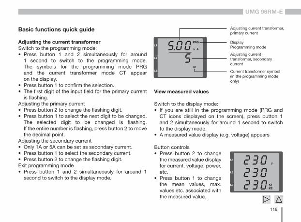
119
UMG 96RM-E
Basic functions quick guide
Adjusting the current transformerSwitch to the programming mode:• Press button 1 and 2 simultaneously for around
1 second to switch to the programming mode. The symbols for the programming mode PRG and the current transformer mode CT appear on the display.
• Press button 1 to confirm the selection. • The first digit of the input field for the primary current
is flashing.Adjusting the primary current• Press button 2 to change the flashing digit. • Press button 1 to select the next digit to be changed.
The selected digit to be changed is flashing. If the entire number is flashing, press button 2 to move the decimal point.
Adjusting the secondary current• Only 1A or 5A can be set as secondary current. • Press button 1 to select the secondary current.• Press button 2 to change the flashing digit. Exit programming mode• Press button 1 and 2 simultaneously for around 1
second to switch to the display mode.
View measured values
Switch to the display mode:• If you are still in the programming mode (PRG and
CT icons displayed on the screen), press button 1 and 2 simultaneously for around 1 second to switch to the display mode.
• A measured value display (e.g. voltage) appears
Current transformer symbol(in the programming mode only)
Adjusting current transformer, primary current
DisplayProgramming mode
Adjusting current transformer, secondary current
Button controls• Press button 2 to change
the measured value display for current, voltage, power, etc.
• Press button 1 to change the mean values, max. values etc. associated with the measured value.

120
UMG 96RM-E
TCP/IP addressing quick guide
Manual TCP/IP settingsSwitch to the programming mode:• Press button 1 and 2 simultaneously for around
1 second to switch to the programming mode. The symbols for the programming mode PRG and the current transformer mode CT appear on the display.
Adjust the TCP/IP address (Adr.)• Press button 2 to select "Adr"• Press button 1 to enable the first digit (byte 0)
of the address (digit is flashing). Press button 2 to set the digit.
• Press button 1 to select the next digit (flashing) and set the desired digit by pressing button 2.
• If byte is set to 0, the address can be set from 1 to 3 by pressing button 1. Then the display jumps back to Byte 0 (no digit is flashing).
Subnet mask (SUb)• Press button 2 to select the subnet mask and set
it in a manner similar to adjusting the address by pressing button 1 and 2.
Adjusting the gateway address (GAt)• Use button 2 and 1 to set the gateway in a manner
similar to adjusting the address. Exit programming mode• Press button 1 and 2 simultaneously to exit the mode
or wait 60 seconds.
Description
Byte identification (e.g. byte 0) of the address
Address data, byte 0
Fig. TCP/IP address, byte 1A TCP / IP address consists of 4 bytes with the following structure:
xxx.xxx.xxx.xxx
Byte 1Byte 0 Byte 2 Byte 3
Enable dynamic IP allocation (dyn)Device/gateway address and subnet mask are assigned by a DHCP server and enable automatic integration of the device into the existing mains.• When in programming mode, press button 2
repeatedly to display the tab labelled "dYn IP".• Press button 1 to enable the parameter "on"
or "oFF" (parameter is flashing). Press button 2 to set the desired status and press button 1 to confirm the selection.
• Exit programming mode.