istt ll 05-19-14 final - clu-in · remediation and technology ... in situ thermal treatment...
TRANSCRIPT

United States Office of Land and Environmental Protection Emergency Management Agency (5102G)
EPA 542-R-14-012 May 2014 www.epa.gov/superfund
Engineering Paper:In Situ Thermal Treatment
Technologies: Lessons Learned

i
Notice and Disclaimer Preparation of this report has been funded by the U.S. Environmental Protection Agency (EPA) Office of Superfund Remediation and Technology Innovation (OSRTI). Information in this report is derived primarily from EPA sources, including personal communications with EPA experts in the field. Some information was also obtained from remediation contractors familiar with the projects discussed in this report. This report is not intended, nor can it be relied upon, to create any rights enforceable by any party in litigation with the United States. Mention of trade names, vendors or commercial products does not constitute endorsement or recommendation for use. A PDF version of Engineering Issue Paper: In Situ Thermal Treatment Technologies is available to view or download from the Hazardous Waste Cleanup Information (CLU-IN) system website at http://clu-in.org. For questions concerning this document, contact James Cummings, U.S. EPA, Technology Assessment Branch, at 703-603-7197// [email protected], or Kira Lynch, Superfund and Technology Liaison, EPA Region 10 at 206-553-2144// [email protected].
Acknowledgements This project was only possible through the commitment of time and effort by regional RPMs and OSCs. They participated in a detailed interview process and provided site-specific information and candid insights to help highlight lessons learned. Sites and associated RPMs and OSCs are listed in Attachment A. Valuable input was provided by the technology vendors who participated in a similar interview process by the project team. Finally, the paper was significantly improved by thoughtful input from reviewers listed in Attachment B.
ii
Terms and Acronyms BTU British thermal unit
COC contaminant of concern
CVOC chlorinated volatile organic compound
DNAPL dense non-aqueous phase liquid
DOD Department of Defense
ERD enhanced reductive dechlorination (anaerobic biodegradation)
ERH electrical resistance heating
GAC granular activated carbon
GPFP guaranteed performance/fixed price
ISTT in situ thermal treatment
LNAPL light non-aqueous phase liquid
MCL Maximum Contaminant Level
MGP manufactured gas plant
MNA monitored natural attenuation
NAPL non-aqueous phase liquid
ORD Office of Research and Development (U.S. EPA)
OSC On-Scene Coordinator
OSHA Occupational Safety and Health Administration
PAH polycyclic aromatic hydrocarbon
PCB polychlorinated biphenyl
PCP pentachlorophenol
PID photo-Ionization detector
PCE perchloroethylene (or tetrachloroethene)
PRP potentially responsible party
RFP request for proposal
RPM Remedial Project Manager
ROD Record of Decision

iii
SEE steam enhanced extraction
STL Superfund and Technology Liaison
SVE soil vapor extraction
SVOC semivolatile organic compound
TCE trichloroethene
TCH thermal conductive heating
TTZ Target Treatment Zone
USACE U.S. Army Corps of Engineers
U.S. EPA U.S. Environmental Protection Agency

iv
Table of Contents Purpose and Scope ............................................................................................................................................. 1
Organization of Paper ............................................................................................................................................... 1
Summary of Lessons Learned ............................................................................................................................. 2
Technology Applicability ........................................................................................................................................... 2
Site Characterization Considerations ........................................................................................................................ 2
Target Treatment Zone (TTZ) Identification ............................................................................................................. 3
ISTT Performance Objectives .................................................................................................................................... 3
Technology Selection ................................................................................................................................................ 3
ISTT Procurement ..................................................................................................................................................... 4
ISTT System Design ................................................................................................................................................... 4
ISTT System Operations and Monitoring .................................................................................................................. 5
ISTT System Monitoring ............................................................................................................................................ 5
ISTT System Closeout ................................................................................................................................................ 6
Data Management/ Communication ........................................................................................................................ 6
Other Considerations ................................................................................................................................................ 6
Technology Descriptions .................................................................................................................................... 8
General Overview of ISTT ......................................................................................................................................... 8
Specific Subsurface Heat Delivery Systems .............................................................................................................. 9
Electrical Resistance Heating ................................................................................................................................ 9
Thermal Conduction Heating .............................................................................................................................. 10
Steam Enhanced Extraction ................................................................................................................................ 11
Fluid Extraction and Recovery ............................................................................................................................. 11
Aboveground Treatment of Extracted Materials ................................................................................................ 12
Process Control ................................................................................................................................................... 13
Technology Applicability ................................................................................................................................... 14

v
General ................................................................................................................................................................... 14
Settings ................................................................................................................................................................... 14
Beneath Operating Industrial Facilities/ Inhabited Residential Structures ......................................................... 14
Beneath the Water Table and at Considerable Depth (>100 feet) ..................................................................... 14
In Low Permeability Strata .................................................................................................................................. 15
In Fractured Rock ................................................................................................................................................ 15
Site Characterization Considerations ................................................................................................................. 16
High Groundwater Flow Regimes ........................................................................................................................... 16
Media Electrical Conductivity ................................................................................................................................. 16
Infrastructure .......................................................................................................................................................... 16
Existing Remediation-Related Infrastructure ...................................................................................................... 16
Utility Infrastructure ........................................................................................................................................... 16
Target Treatment Zone (TTZ) Identification ....................................................................................................... 18
Establishing ISTT System Performance Objectives ............................................................................................. 20
Quantitative Performance Objectives .................................................................................................................... 20
Semi-quantitative Performance Objectives ............................................................................................................ 20
Qualitative Performance Objectives ....................................................................................................................... 20
Residual Contamination Considerations ................................................................................................................. 20
Technology Selection ........................................................................................................................................ 21
Combining ISTT Remedies ...................................................................................................................................... 21
Combining ISTT with Other Polishing Technologies ............................................................................................... 21
ISTT System Procurement .................................................................................................................................. 23
Useful Vendor Information Resources ................................................................................................................... 23
Design/Build ............................................................................................................................................................ 23
Performance Bonds ................................................................................................................................................ 23
Payment Bonds and Retainage ............................................................................................................................... 23
Risk Allocation ......................................................................................................................................................... 24

vi
Progress Payments .................................................................................................................................................. 24
Financial Risk Profile ............................................................................................................................................... 24
Guaranteed Performance Fixed Price (GPFP) ......................................................................................................... 26
Power Procurement ................................................................................................................................................ 26
ISTT System Design............................................................................................................................................ 27
Other ISTT System Design Considerations .......................................................................................................... 28
Materials Compatibility ...................................................................................................................................... 28
Bench- and Pilot-Scale Studies ............................................................................................................................ 28
Modeling ............................................................................................................................................................. 28
Surface Seals ....................................................................................................................................................... 28
Generation of Fines in Wells and Recovery Systems ........................................................................................... 28
Moisture Addition Around Electrodes ................................................................................................................. 29
Selection and Sizing of Off-Gas Treatment Equipment ....................................................................................... 30
Site Preparation and Remedy Installation .......................................................................................................... 30
Waste Generation during System Installation .................................................................................................... 30
Refining the Conceptual Site Model during Remedy Installation ....................................................................... 31
System Layout ..................................................................................................................................................... 31
ISTT System Operations and Monitoring............................................................................................................ 32
System Startup ........................................................................................................................................................ 32
Monitoring .............................................................................................................................................................. 33
Compliance Monitoring .......................................................................................................................................... 33
System Adjustments ............................................................................................................................................... 33
Data Management/ Communications .................................................................................................................... 34
ISTT System Closure ................................................................................................................................................ 34
Confirmatory Sampling ....................................................................................................................................... 34
Infrastructure Abandonment .............................................................................................................................. 35
Miscellaneous Considerations ........................................................................................................................... 36

vii
Site Security ............................................................................................................................................................ 36
Subsidence .............................................................................................................................................................. 36
Byproducts .............................................................................................................................................................. 36
Attachment A – List of RPMs/OSCs/STLs Contacted ........................................................................................... 37
Attachment B – Reviewers ................................................................................................................................ 38

1
Purpose and ScopeThe purpose of this paper is to convey useful information gained from approximately 10 years of development and deployment of in situ thermal treatment (ISTT) technologies.
This paper is the result of a series of in-depth interviews with U.S. Environmental Protection Agency (EPA) Remedial Project Managers (RPMs) and On-Scene Coordinators (OSCs) and with ISTT vendors whose experience extends beyond federal response action sites to include state-regulated cleanups and Brownfields/voluntary cleanups, as well as international projects. While the focus is on federally-funded cleanup sites, many of the lessons learned will be of interest to RPMs and OSCs who are overseeing potentially-responsible party (PRP)-lead cleanups.
This paper represents one of the first efforts to organize and compile information on practitioner experience with specific remedial technologies. The objective was to be as comprehensive as possible within the limits of time and resources. Additional lessons learned will emerge as ISTT remedies, both alone and in conjunction with other technologies, continue to be deployed. We hope to continue the lessons learned effort.
Organization of Paper This paper is organized in a manner that seeks to maximize utility for a variety of users with varying
interests. The first section consists of declarative statements of ‘Lessons Learned’ with limited explanatory narrative. Subsequent sections of the report provide additional information.
The following section, Summary of Lessons Learned, generally mirrors the body of the paper and is organized into these major sections:
• Technology Applicability • Site Characterization Considerations • Thermal treatment Zone (TTZ) Identification • ISTT Performance Objectives • Technology Selection • ISTT System Procurement • ISTT System Design • ISTT System Operations and Monitoring • ISTT Monitoring • ISTT Closeout • Data Management/Communication • Other Considerations
Readers who are in a particular phase of a project or have a specific question can refer to the most relevant section. (Please note: The Lessons Learned were placed in the section that seemed most appropriate. Some of the lessons learned may apply to multiple categories.)

2
Summary of Lessons LearnedTechnology Applicability • In Situ Thermal Treatment (ISTT) is particularly
suitable for sites with significant contaminant mass (variously described as source zone(s), free product, non-aqueous phase liquid (NAPL), or hot spots)
• ISTT has been used to treat a wide variety of contaminants, including:
- Chlorinated volatile organic compounds (CVOCs)
- Semivolatile organic compounds (SVOCs) - Total petroleum hydrocarbons - Polycyclic aromatic hydrocarbons(PAHs)
including creosote and coal tar - Polychlorinated biphenyls (PCBs) - Pesticides
• ISTT has been used at a variety of site types, such as:
- Industrial facilities, Department of Defense and Department of Energy installations using solvents as degreasers
- Dry cleaners - Solvent repackagers and recyclers - Bulk terminals - Wood treaters which used creosote and/or
pentachlorophenol (PCP) - Former manufactured gas plants (MGPs) - Pesticide formulators/repackagers
• ISTT has been used in a variety of settings:
- Beneath operating industrial facilities/commercial buildings/inhabited residential structures
- Beneath the water table - At considerable depth below ground surface
(>100 feet) - In low permeability strata - In fractured rock
Site Characterization Considerations • The electrical resistance heating (ERH) and
thermal conductive heating (TCH) variants of
ISTT are less affected by heterogeneous and low permeability lithologies. - Thermal conductivity varies by a factor of
approximately ±3 over a range of 106 permeabilities.
- ERH and TCH are often chosen specifically because heterogeneous and/or low permeability conditions limit or preclude the use of fluid-delivery based remedial technologies.
• High groundwater flow regimes (greater than approximately 1 foot per day [ft/d]) have been one of the principal factors hampering achievement of performance objectives for ERH and THC projects.
- Such groundwater flow regimes can act as a continuing heat sink hampering or precluding achievement of the necessary subsurface temperatures.
- NOTE: Such high groundwater-flow regimes are relatively rare. Furthermore, contamination in such zones may already have been reduced by groundwater flow.
- Dewatering or diversion may be necessary.
• Media conductivity (e.g., debris) may affect ERH applicability or performance.
• Identify and ensure proper closure of existing monitoring wells, etc., in treatment volume prior to heating (also applies to wells previously closed prior to ISTT remedial efforts).
- Depending on the specific ISTT application, temperature and pressure increases can be significant
• Buried utilities are usually not a problem; however, identification and, where necessary, modifications of design and/or operation are important. Most utility infrastructure is within six feet or so of the surface.
- Ensure identification and, where necessary, cut off or control of utility corridors and sewer lines that may serve as a preferential pathway for offsite vapor migration.

3
Target Treatment Zone (TTZ) Identification • Treatment volume is a primary factor in the cost
of ISTT.
- Conceptual site model (CSM) refinement efforts that more accurately define the volume requiring thermal treatment are a good investment.
• If ISTT is to be the primary or only remediation technology, it is desirable to match the ISTT system footprint to the source zone(s) to be treated.
- At sites with groundwater plume restoration objectives, failure to adequately treat the source(s) will hamper or frustrate achievement of Remedial Action Objectives (RAOs).
- If untreated source material is upgradient, treated source areas are likely to be re-contaminated.
- TTZs may be defined as volumes of known or suspected NAPL and/or may be circumscribed by a concentration isopleth.
ISTT Performance Objectives • A variety of quantitative and semi-quantitative
ISTT performance objectives have been developed, including:
- Achievement of specified post-treatment concentrations (e.g., 1 part per million [ppm]) in soil and/or groundwater
- Specified percentage reductions (e.g., 99 percent) in contaminant concentration
- At sites where contaminant quantities have been estimated, performance objectives stated as pounds of contaminants recovered (NOTE: This metric can be problematic due to uncertainties in initial contaminant mass)
- Removal of contaminants to the ‘maximum extent practicable’ (In this case, ISTT termination is often based on substantial reductions as demonstrated by asymptotic trends in contaminant recoveries.)
• Compliance with soil performance objectives is usually determined using a statistical averaging approach, e.g., site-wide average of ‘X’ with no
outlier >5-10X. The latter provision is to ensure that a hot or warm spot that has been inadequately heated is not ‘averaged out.’
• More general performance objectives have included achieving and maintaining a specified temperature for a specified period of time.
Technology Selection • Specifying generic ISTT in a Record of Decision
(ROD) and a request for proposal (RFP) for CVOC sites will allow vendors of different ISTT technologies to participate in bidding.
- Most ISTT technologies can achieve temperatures necessary to treat prevalent contaminants like tetrachloroethene (PCE) and trichloroethene (TCE).
• In the presence of moisture, the eutectic boiling point of contaminants may be significantly reduced.
- The pure product boiling point of PCE is 121ºC. The eutectic boiling point is 88ºC.
- The boiling point of TCE is similarly reduced from 87ºC to 73ºC.
• To date, when used as a stand-alone technology, steam enhanced extraction (SEE) has primarily been used to address PAH contamination from wood treaters.
- Although many PAHs have boiling points well above 100ºC, the many processes involved in SEE remediation are able to address most of the constituents in these multi-component wastes.
• For sites with higher molecular weight SVOCs with higher boiling points and more stringent cleanup goals, TCH may be the only option.
- TCH was originally developed to address PCB contamination and has also been used to remediate creosote, dioxin and PCP at a wood treating facility and coal tar PAHs from a former MGP site.
• A number of cleanups have involved use of more than one form of ISTT.
- Hydrogeological conditions across a site may vary sufficiently to suggest the use of SEE in

4
higher permeability zones and ERH or TCH in lower permeability strata.
• As discussed above, ISTT is generally most suitable for source areas. ISTT can be combined with other ‘polishing’ technologies to facilitate site closure.
• While experience in combining remedies is still limited, ISTT has some potentially beneficial effects on downgradient groundwater remedies. For example, ISTT often results in significant increases in dissolved phase carbon that is beneficial for enhanced reductive dechlorination (ERD).
• In addition, research has shown that dechlorinating microorganisms thrive in the temperature range of 30ºC to 35ºC. [CITATION]
ISTT Procurement • The number of vendors offering ISTT services is
limited.
- ISTT technologies may be subject to patent protection or licensing requirements.
• Vendor resources are available in the early stages of remedy scoping.
- Vendors have web sites with planning resources that can be helpful.
- Pre-bid meetings and site walks have been used to inform the preparation of RFPs and to improve the quality of vendor bids.
• Design/build has been the most prevalent method of ISTT service procurement.
- ISTT projects are best viewed as engineering services procurement.
- While all thermal vendors achieve cleanup goals by application of thermal energy, each vendor has specific equipment and procedures. Thus, the design/bid/build approach whereby different firms perform each phase of the project is generally not suitable for ISTT procurements. General practice it to hire the same firm to design, build and operate the system.
• Performance bonding requirements have been problematic.
- Equipment and practices vary significantly among vendors; thus, it would be difficult and costly to replace vendors once a project has started.
- At times, performance bonds have been unavailable or only available at considerable cost. (NOTE: Some vendors report that performance bonding availability has improved.)
• Payment bonds and retainage are useful tools to ensure desired performance.
• Equitable risk allocation is important.
- While it may be possible to transfer risk to vendors, such transfers impose costs as vendors will increase the contingency components of their bids as a function of their level of discomfort with the associated uncertainties.
• Progress payments schedules should be reasonable.
- Most ISTT vendors are small firms with limited ability to carry costs. Onerous provisions regarding timing or conditions for payment should be avoided.
- Where feasible, procure electrical power or other required energy supplies under a separate task order. Such an approach can save costs by avoiding vendor mark-up.
ISTT System Design • For many CVOCs (PCE, TCE, etc.) and
hydrogeological regimes, vendors have sufficient experience to design and operate an ISTT system without the need for pilot studies.
- Vendors can provide input regarding whether a pilot test is necessary and identify the factors suggesting the need for a pilot scale study, e.g., unusual contaminants and/or subsurface conditions.
• ISTT vendors have thermal models that allow them to predict treatment timeframes and energy requirements.
- While these models have become more sophisticated as vendors have gained full-scale field experience, there are still some uncertainties associated with the model

5
outputs. Vendors should be expected to bear the risk of modeling uncertainties
• Surface seals may be used to improve vacuum influence, prevent rainfall infiltration and to provide surface insulation to prevent unwanted condensation of contaminant vapors in near surface soil.
- The need for such seals will be based on factors such as proximity to the surface of heating activities and local meteorological conditions.
- Vendors can provide input on the need for surface seals.
- Existing surface seals may not be sufficient, i.e., paved surfaces may have gravel sub-grades that can create problematic preferential pathways for vapors, particularly for projects for which heating is required near the surface.
• Although uncommon, ISTT systems have the potential to result in significant generation of fine material in extraction wells that may require handling as a hazardous waste. Generation of fines may be preventable through careful well screen and sand pack design.
• For ERH in the vadose zone, water must be added adjacent to electrodes to prevent soil drying and ensure electrical current flow.
• It is possible to heat discrete zones both horizontally and vertically.
• ISTT has been used to treat contamination beneath inhabited buildings.
• Angular, horizontal, and sheet pile electrodes have been used to augment traditional vertical electrodes.
• It is important to contact local utilities regarding power and equipment availability.
- Power limitations can delay project initiation and/or require phasing the project. This is particularly the case in areas undergoing development.
- Infrastructure upgrades may be necessary and associated costs must be incorporated in cost estimates
• High levels of contamination in the subsurface will result in significant volumes of mobilized mass.
- For many contaminants, volatilization and recovery are the primary treatment mechanisms.
- Proper specification and sizing of off-gas treatment components is critical.
- Contaminant volume and granular activated carbon (GAC) compatibility will determine whether GAC or some other forms of recovery and treatment, such as thermal oxidation, are appropriate.
• Treatment System components can be installed entirely below grade.
- Electrodes, heater elements, piping and wiring can be installed and operated below grade so as to avoid conflict with facility operations or pedestrian/vehicular traffic. Surface equipment can be located in an un-intrusive location.
ISTT System Operations and Monitoring • Vendors will make frequent/periodic
adjustments throughout the course of the heating campaign.
- Adjustments are likely to be more frequent than are generally the case for soil vapor extraction (SVE) or pump and treat systems, which may operate for extended periods of time with limited adjustment.
• Flexible, adaptive implementation is key to project success.
- As monitoring indicates achievement of performance objectives in some portions of the site, heating of sub-areas can be discontinued, allowing shifting power to zones not cleaning up as quickly.
- Installing additional equipment in an existing ISTT field has been performed but may be more complex and costly than initial ISTT system installation.
ISTT System Monitoring • Operational, performance, and compliance
monitoring are important aspects of ISTT system operation for achievement of performance objective.

6
• Operational parameters include temperature, pressure and energy input
− Thermocouples or digital electronic temperature sensor are used to monitor temperature in the TTZ.
- Thermal sensor strings are often placed at the centroid of electrode or heater arrays and at extraction wells to measure temperature in the area most difficult to heat.
• Performance parameters – e.g., subsurface temperatures, contaminant extraction rates - measure progress in meeting performance objectives.
• Compliance monitoring includes:
- Regulatory requirements associated with air emissions and water discharges. Depending on the contaminants of
concern ( COCs) and the quantities to recovered and/or treated, local regulations may specify limits for air emissions and water discharges
Indoor air limits in buildings for ISTT projects beneath inhabited structures.
Ambient air monitoring particularly when ISTT is conducted in proximity to inhabited structures
- Occupational Safety and Health Administration (OSHA ) requirements specify a standard of 50 volts for stray voltages at ERH sites Vendors generally report adhering to a
12-volt standard.
- Determining final performance of the ISTT system. If treatment performance objectives
include dissolved phase contaminant concentrations, groundwater monitoring duration should be specified.
- ‘Hot sampling’ procedures for soil and groundwater are available to allow sample collection before the site returns to ambient temperature Hot sampling procedures allow sample
collection without loss of VOCs which
would otherwise give an inaccurate indication of ISTT performance.
Hot sampling allows discontinuing heating of zones that have met cleanup goals, allowing power to be concentrated in zones not cleaning up as quickly.
As a Health and Safety consideration, close coordination between sampling contractors and ISTT vendors is critical. Hot sampling may require temporary discontinuation of heating activities.
ISTT System Closeout • As a rough rule of thumb, sites generally cool at
a rate of approximately 1ºC/day.
- Cooling rates at some sites have been considerably slower than this rule of thumb
- Groundwater flow rates affect cooling rates - Water can be added following completion of
heating to quench hot soils and speed the cooling process
• Following ISTT system shutdown determination, surface equipment will be demobilized from the site.
• Subsurface equipment is often abandoned in place, subject to local jurisdiction requirements.
Data Management/ Communication • Site-specific web sites are increasingly prevalent.
- Facilitates data management and team communications
- Allows (near) real time uploading of operational and performance monitoring data
Other Considerations • Security fencing and monitoring are necessary.
- Prevents theft of valuable equipment and materials such as copper cables.
- Protects trespassers.
• Subsidence has generally not been a problem.

7
- May be a concern if heating clay-rich zones near the surface or in unconsolidated fill
• Some sites have experienced formation of byproducts such as acetone.
- Soil total organic carbon (humus) slowly degrades and acetone is one of its products. Heating accelerates the degradation of organic carbon and can cause temporary increases in acetone and other ketones as sites with high organic carbon (e.g., peat)

8
Technology Descriptions
General Overview of ISTT Various approaches have been developed and implemented to deliver energy to the subsurface to address contamination at hazardous waste sites. Regardless of the specific ISTT method, heat applied to the subsurface will have similar effects on physicochemical properties such as vapor pressure, viscosity and aqueous solubility of organic contaminants. Changes in physical properties as temperatures increase above ambient are summarized in Table 1.
Heating the subsurface accelerates both the rate and degree of contaminant mass recovery from the target treatment area. Thermal treatment can also catalyze in situ destruction, such as hydrolysis and pyrolysis, and has been shown to have a potentially beneficial effect on microbial degradation rates. Detailed discussion of ISTT technologies have been summarized in several existing publications, including U.S. Environmental Protection Agency (U.S. EPA), 2004, and U.S. Army Corps of Engineers (USACE), 2009, guidance. A general overview of commonly applied ISTT technologies is provided below.
Table 1. Changes in Physical Properties Below 120ºC Component Property
Oil-Based LNAPL
Chlorinated Solvents
Creosote Coal Tar PCB Comment
Vapor Pressure Increase Value
20-800 20-100 Not significant
Not significant
Not significant
Abundance of data in literature
Solubility Increase Factor
2-100? 1.5-3 10-1000 10-1000 10-1000 Chlorinated solvent less affected than larger hydrocarbons
Henry’s constant increase factors
10-20 0-10 0-10 0-10 Data absent for most compounds, some decrease
Viscosity reduction factor
2-100+ 1.3-3 5-10 20-100+ 3-1000 The higher initial viscosity, the more reduction
Interfacial tension reduction
<2 <2 2-5 1-5 1-5 Typically not dramatic effect (less than factor 2)
Density reduction (%)
10-20 10-20 10-20 10-20 10-20 PAH DNAPLs may become LNAPLs
Kd (reduction factor)
? 1-10 5-100 5-100 NA Estimates based on limited data
Source: G. Heron, personal communication 2013 DNAPL= dense non-aqueous phase liquid; LNAPL= light non-aqueous phase liquid

9
Specific Subsurface Heat Delivery Systems The most commonly applied ISTT methods are ERH, TCH, and SEE.
Other in situ heating methods, such as radio frequency heating and steam injection via soil mixing augers, are also available.
A pilot scale study has been completed for an in situ thermal technology that seeks to destroy wastes with suitable British thermal unit (BTU) value, such as creosote and coal tars. The technology involves injecting heated air into the subsurface to reach the auto-ignition point of the wastes. Continued air injection seeks to propagate a combustion front in a process akin to smoldering.
As discussed below, it is also possible to combine several of these heating methods at a site. For example, SEE has been combined with TCH or ERH to provide complementary heating capabilities for zones with different hydrogeological properties.
Although the subject of this paper is ISTT, TCH has been used in an ex situ configuration.
Electrical Resistance Heating ERH uses an electrode system to pass electrical current through the thin layer of moisture that coasts the soil grains. The flow of current creates heat as the soil acts as an electrical resistor. The maximum temperature that can be reached in situ using ERH corresponds to the boiling point of water at the local pressure condition (generally from approximately 100ºC to 120ºC). The typical configuration is shown on Figure 1.
Electrodes are typically constructed of graphite, steel, or other electrically conductive material within a borehole. Arrays of electrodes are installed in the TTZ. Multiple (“stacked”) electrodes can be constructed in a single boring to allow differentiation in the vertical heating of the target treatment zone or to heat thick treatment zones. Electrical power is delivered to the electrode arrays by power controllers. Isolation transformers are used to ensure that electrical current applied in situ flows only between installed electrodes.
Figure 1. Typical ERH System Configuration
Vadose zone electrodes are usually equipped with an electrode wetting system, with water or a salt solution is supplied to each electrode. Without an electrode wetting system, soil around the electrodes may dry out, interrupting current flow
Volatized contaminants are captured by vacuum extraction wells and delivered to the surface for recovery and/or treatment as necessary depending on the volume of contaminants and local air permit discharge requirements.
10
ERH can be effectively applied to both coarse-grained and fine-grained media as well as sites with inter-bedded fine and coarse grained strata and fractured bedrock. Sites with very fast groundwater flow rates (for example, greater than 1 ft/d) may pose challenges for this technology as the groundwater acts as a heat sink. Sites that have unusual or altered subsurface conditions, such as landfills or waste disposal pits filled with non-native material, may be problematic to treat with ERH, due to the non-uniform or poor electrical conductivity of the material.
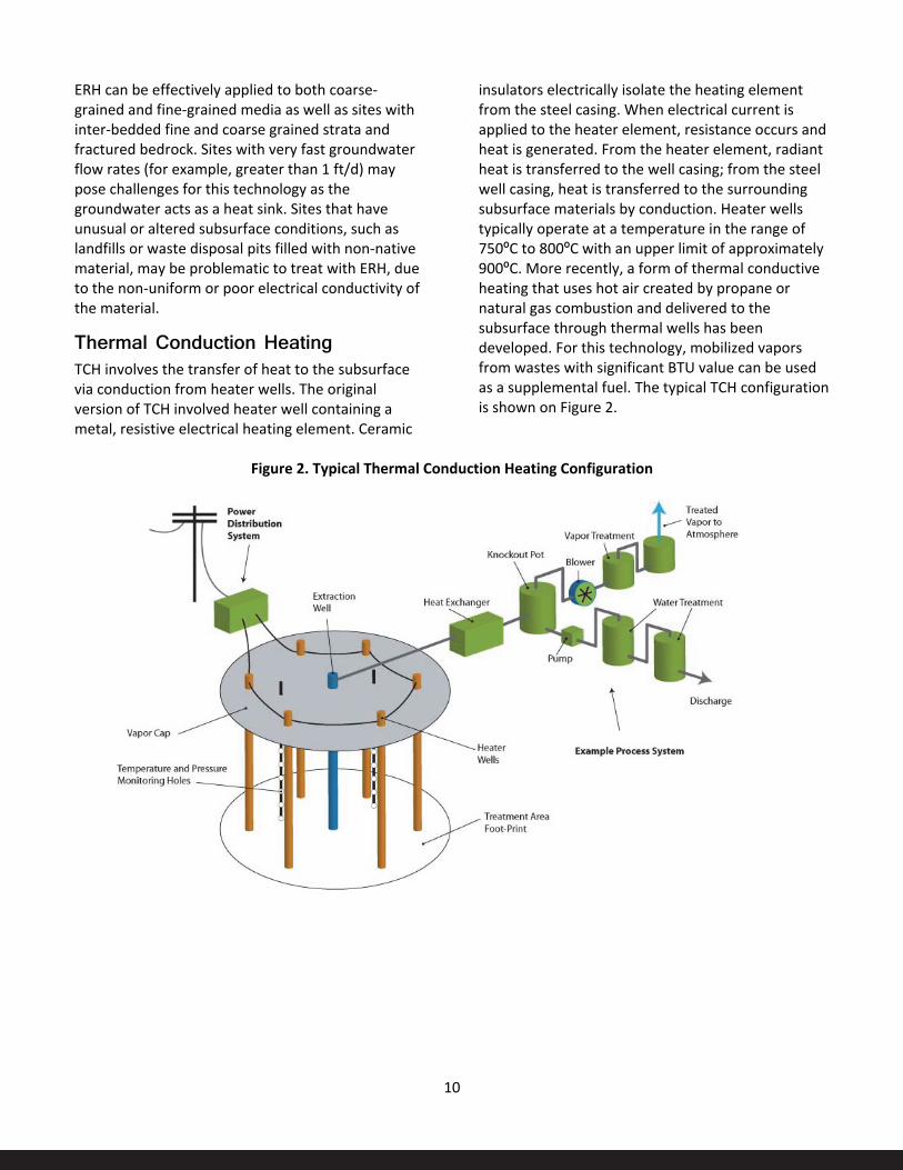
Thermal Conduction Heating TCH involves the transfer of heat to the subsurface via conduction from heater wells. The original version of TCH involved heater well containing a metal, resistive electrical heating element. Ceramic
insulators electrically isolate the heating element from the steel casing. When electrical current is applied to the heater element, resistance occurs and heat is generated. From the heater element, radiant heat is transferred to the well casing; from the steel well casing, heat is transferred to the surrounding subsurface materials by conduction. Heater wells typically operate at a temperature in the range of 750ºC to 800ºC with an upper limit of approximately 900ºC. More recently, a form of thermal conductive heating that uses hot air created by propane or natural gas combustion and delivered to the subsurface through thermal wells has been developed. For this technology, mobilized vapors from wastes with significant BTU value can be used as a supplemental fuel. The typical TCH configuration is shown on Figure 2.
Figure 2. Typical Thermal Conduction Heating Configuration

11
Heater spacing design is site specific and controlled by the required heating objectives, target treatment temperature, desired operating duration, and subsurface conditions. Sustained heating of the treatment zone will result in the vaporization of water within the soil matrix. Temperatures in excess of 500ºC (>1,000ºF) can be achieved in the vadose zone or at sites where continuous dewatering can be achieved.
Electrically-based TCH heater well arrays utilize power controllers to manage the electrical load delivered to the heater wells; however, TCH heater wells do not require wetting systems since the efficiency of thermal heat conduction is not reduced by drying of soil around the heater wells. TCH wells can be placed at various spacings within the TTZ if desired.
TCH has been applied to both coarse-grained and fine-grained media, media with inter-bedded coarse and fine grained strata, and fractured rock sites. Sites with very fast groundwater flow rates (e.g., greater than 1 ft/d) may pose challenges for this technology.
At sites where the target treatment temperature is 100C, only a very small fraction (~2-3%) of the TTZ immediately adjacent to the heater wells will exceed the boiling point of water.
Steam Enhanced Extraction SEE uses steam injection to heat the subsurface. Steam heating is most applicable to sites where hydraulic conductivities of the bulk formation are sufficient to allow steam to be efficiently injected (e.g., generally greater than approximately 10-4 centimeters per second). Similarly SEE can be used in higher groundwater flow regimes which may be less suitable or unsuitable for ERH or TCH.
SEE relies on wells to inject steam and extract hot heated contaminants, groundwater and other fluids. Subsurface heating occurs initially through the transfer of latent heat to the aquifer during steam condensation in the vicinity of the steam injection wells. As subsurface temperatures increase around the injection point, the condensation front moves radially outward. With continued steam injection,
the condensation front eventually intersects system extraction wells where vapor, groundwater, and displaced fluids, including NAPL, are recovered. Thermal conduction and convection also play a role in heat transfer into the less permeable portions of the aquifer. Frequently, SEE sites are operated in an “outside-in” mode, with steam injected around the perimeter of known contamination. This approach is intended to push contamination toward the central portion of the remediation zone for extraction. The typical SEE configuration is shown on Figure 3.
Steam used for subsurface heating typically is generated onsite through combustion of fuel oil or gas (e.g., propane) in a packaged, portable boiler system. Non-condensable gases recovered during remedial system operations can be used as a supplemental fuel. At active industrial facilities where steam is produced for manufacturing purposes, SEE has been successfully applied using excess generation capacity of pre-existing stationary boilers as well. Injection wells are constructed with equipment to control and monitor the pressure and flow of steam injected to the subsurface. SEE also has been combined with other heating technologies, with steam applied to highly permeable portions of the formation and other technologies, such as TCH and ERH, applied to less permeable zones.
Fluid Extraction and Recovery Fluid extraction and recovery are integral components for nearly all ISTT applications. SVE is the most commonly applied fluid recovery technology for ISTT systems and may be sufficient for CVOCs such as PCE and TCE. Multi-phase extraction systems are also commonly applied at ISTT sites for removing combinations of groundwater, soil vapor, steam, and NAPL.
Effective fluid extraction during thermal treatment is critical to maintaining both hydraulic and pneumatic capture within the treatment area. Fluid extraction points may be located in the centroids of electrode/heater well arrays and/or may be co-located with electrodes or heater wells. Typically, multiple fluid extraction points are combined above ground at manifolds to minimize the amount of conveyance piping required to transfer the extracted materials to the treatment system.

12
Figure 3. SEE System Schematic
Aboveground Treatment of Extracted Materials Treatment of recovered fluids typically begins with the separation of liquid and vapor. The separation process is often enhanced by the addition of a heat exchanger with a non-contact cooling source provided by a chiller or cooling tower. Recovered liquids and condensate from the vapor-liquid separation are often treated using GAC. If recovery of NAPL is anticipated, oil-water separation may precede GAC treatment operations. When contaminant properties allow, extracted groundwater and condensate may be treated through air stripping. Sedimentation and filtration processes may also be included prior to GAC treatment if significant total suspended solids are present in extracted groundwater.
At sites impacted by VOCs, most contaminant mass will be extracted in the vapor phase. GAC and thermal oxidation are the most frequently applied vapor treatment methods. Vapor treatment approaches that incorporate onsite carbon regeneration with steam (rather than offsite treatment/disposal) are also applied. A limited number of thermal applications to date have been
completed using cryogenic-based (low temperature) vapor treatment.
The amount of contaminant mass projected to be extracted via vapor recovery generally dictates the type of vapor treatment system selected. For sites where greater than approximately 5,000 to 20,000 pounds of vapor are expected to be recovered and treated, oxidation methods or steam-regenerated GAC may be more cost effective than sacrificial GAC. Where a non-condensable vapor is expected, adsorption processes can be challenged since the efficiency of carbon is strongly influenced by temperature and humidity level in the vapor stream. Under elevated temperature and moisture conditions, GAC adsorption capacity is reduced and effective removal using this technology may require larger carbon beds, more frequent media regeneration/replacement, or vapor stream conditioning (e.g., cooling below the dew point then supplemental heating for drying).
Treatment of chlorinated methanes, fluorinated refrigerants, and solvents that are weakly adsorbed to GAC, such as vinyl chloride, are notable examples where specially designed or even multiple vapor

13
treatment approaches may be needed to effectively manage vapor phase effluent.
Process Control ISTT systems instrumentation typically includes the use of thermocouples or digital electronic thermal
sensors to monitor in situ temperature. Thermal sensor arrays are usually placed at the centroid of electrode and/or heater well arrays. Additional parameters of interest include subsurface vacuum pressure, and flow rates of recovered fluids.

14
Technology ApplicabilityGeneral ISTT is particularly suitable for sites with appreciable contaminant mass (variously described as source zone(s), free product, NAPL, or hot spots).
ISTT is often chosen to address contamination in low permeability strata and/or in the saturated zone.
ISTT has been used to treat a wide variety of contaminants, including:
• CVOCs, such as PCE and TCE, , and SVOCs • Petroleum hydrocarbons • PAHs such as those found in creosote and coal
tars • PCBs • Pesticides
ISTT has been used at a variety of site types including:
• Industrial facilities and Department of Defense (DOD) installations using solvents as degreasers
• Dry cleaners • Solvent repackagers and recyclers • Bulk terminals • Wood treaters • Former MGPs • Pesticide formulators/repackagers
Settings ISTT has been used in a variety of settings, as described below.
Beneath Operating Industrial Facilities/ Inhabited Residential Structures ISTT has been employed beneath large operating industrial facilities and smaller retail facilities such as dry cleaners as well as vacant facilities. When facilities are occupied, measures are implemented to monitor indoor air.
AF Plant 4, TX – ERH beneath Operating Industrial Facility
ERH was used to address solvent contamination beneath an industrial facility while the plant was in operation. Air Force Plant 4, Dallas/Fort Worth, Texas involved 24/7aircraf construction activities. Innovative placement of electrodes and equipment including the use of angled borings allowed heating of the target volume. Continuous monitoring of air quality inside the plant revealed no exceedances of OSHA standards.
Beneath the Water Table and at Considerable Depth (>100 feet) ISTT has been used to treat dense non-aqueous phase liquid (DNAPL) in the saturated zone. Historically, DNAPL remediation was thought to be problematic because the contamination was often located below the water table.
In addition, ISTT has been used from near the surface to depths greater than 100 feet below ground surface.

15
Wood Treater, Visalia, CA – SEE Results in Deletion from the NPL
The Visalia, California, wood treater site has been deleted from the NPL following use of Steam Enhanced Extraction (SEE) to address creosote and PCP contamination from long term wood treatment operations. With a surface footprint of approximately 2 acres, the SEE effort addressed contamination to a depth of 130 feet, well below the water table. SEE removed or destroyed in situ an estimated 1.3 million pounds of contamination. A pump and treat system had been in operation since 1976 at a cost of approximately $1M/year. In its latter stages the pump and treat (P&T) system had been covering as little as 10 pounds per week.
Following SEE, the P&T system was put on standby status pending the results of 2 years of confirmatory monitoring. At the end of the monitoring period, the P&T system was dismantled.
In Low Permeability Strata As noted above, ISTT is often chosen specifically because heterogeneous and/or low permeability conditions limit or preclude the use of other remedial technologies. ISTT has been applied in both unconsolidated and consolidated media.
ERH and TCH are suitable for use in heterogeneous and low permeability lithologies. Thermal conductivity only varies by a factor of approximately ±3 over a range of 106 permeabilities.
ISTT has been deployed at sites with bay muds, tight clays and high humic content peat materials.
Camelot Cleaners, Fargo, ND – Tight Clays
ERH was used to address PCE contamination in very tight clays at a former drycleaner in West Fargo, ND. Drillers reported having to unwrap the clay from the augers. The Camelot site is the only known site where appreciable subsidence has occurred as a result of ISTT application.
In Fractured Rock Both ERH and TCH have been used to address contamination in fractured rock. ERH applications have been primarily in sedimentary rock (sandstone and limestone) at depths as deep as 100 feet. TCH has been used in sedimentary and metamorphic rock (limestone, chalk, mudstone and gneiss as deep as 90 feet.
Heat up rates and energy input requirements are reported as being similar to soil. Incremental costs are to be expected for installation of electrodes or heater wells as a function of the specific type of rock involved.
ERH vendors can determine the electrical conductivity properties of the media and to design systems accordingly.
Heating rates can be faster and energy requirements can be considerably less at fractured rock sites. For example, in fractured rock below the water table where the fracture porosity is much less than typical soil porosity, there is much less water to heat up and boil than in soil.

16
Site Characterization Considerations ISTT is not affected by many of the site conditions (discussed below) that hamper effective use of other in situ remedial technologies.
Perhaps the most important element of site characterization is adequately bounding the treatment volume. Significant mass left outside the TTZ may hamper or preclude achievement of performance objectives.
The purpose of this section is to discuss factors which may affect ISTT selection or performance.
High Groundwater Flow Regimes Perhaps the main subsurface feature that has hampered achievement of target temperatures is significant groundwater flow (greater than approximately 1 ft/d). Such flow regimes can act as a continuing heat sink. Because of high groundwater transmissivity, such zones may be relatively free of contamination, but adjacent lower permeability zones may have much higher levels of residual contamination. Such zones can be difficult to heat if groundwater flow is not controlled.
A priori detection of such paleochannels and other transmissive subsurface features may not always be possible.
Media Electrical Conductivity ERH systems are able to handle a fairly wide range of subsurface conductivities. Nevertheless, in some situations (e.g., fill or gravel layers), media electrical conductivity may affect ERH applicability and performance.
Groveland Wells, MA – ERH Affected by Media Electrical Conductivity
ERH was deployed to address solvent contamination at the Groveland Wells Superfund site. During implementation, temperature monitoring indicated that a zone near the surface was not heating properly. Subsequent investigation determined that the zone comprised fill material with electrical conductivity properties considerably different than the remainder of the site.
Equipment provided by the ERH vendor could not be modified to handle the conductivity difference. The fill was sufficiently permeable to allow installation of an SEE system demonstrating that it is possible to make significant retrofits within the footprint of an existing system, albeit at additional cost.
Infrastructure Existing Remediation-Related Infrastructure Existing PVC monitoring wells within the treatment volume should be properly abandoned prior to heating. In addition, previously abandoned borings should be reviewed to ensure the adequacy of abandonment methods in light of the temperatures and pressures associated with a specific ISTT deployment. Use of bentonite is generally not a sufficient means of abandonment prior to ISTT.
Utility Infrastructure Several aspects of utility infrastructure should be considered and addressed.
Sewer lines and utility corridors can serve as preferential pathways for the transport of vaporized contaminants. Such pathways should be identified and cutoff or otherwise controlled by vacuum influence.

17
Similarly, near surface ISTT operations beneath existing paved surfaces must take into consideration the potential for preferential pathways associated with gravel subgrades below such surfaces.
Existing conditions such as buried utilities are usually not a problem; however, identification, and where necessary, system design and/or operation modification may be necessary. Most utility infrastructure is within six feet or so of the surface.
SRSNE Site, CT – Utility Infrastructure
Follow-on site characterization work after selection of the ISTT remedy identified the presence of an optical fiber cable cutting across the treatment footprint. While it may have been possible to design the ISTT system to avoid impacts, the importance of the cable in supporting telecommunications on the East Coast resulted in substantial delay as new easement language to support its relocation was negotiated.
18
Target Treatment Zone (TTZ) IdentificationISTT is generally most suitable for zones of significant contamination. (TTZs have been specified as zones of significant NAPL contamination. They have also been specified as the volume within a specified groundwater concentration isopleth, such as 10 ppm.
Treatment volumes are a primary driver of ISTT costs. In general, CSM refinement efforts which reduce the volume requiring thermal treatment are a good investment.
SRSNE Site, CT – Treatment Volume Reduction
Initial estimates of volumes requiring remediation, based on direct observation of NAPL, historical records and ‘indicator’ criteria, ranged from 200,000 to 800,000 cubic yards. Collaborative efforts between the PRPs and EPA Region 1 and Office of Research and Development (ORD) staff resulted in a one-week field program to refine the extent of NAPL contamination. Representatives from all parties were in the field during the investigation. Cores from drilling locations that were mutually agreed to were assessed visually with a photo-ionization detector (PID), and by performing simple shake tests of contaminated soils mixed with water and NAPL-sensitive dye (http://www.epa.gov/region1/ superfund/sites/srs/225370.pdf). These investigations resulted in the delineation of the actual NAPL contaminated area final estimated treatment volume of approximately 60,000 cubic yards. The volume reduction significantly reduced the projected costs and facilitated implementation.
Dunn Field/Memphis Depot, TN – Treatment Volume Reduction
TCH was used to recover more than 12,000 pounds of CVOC contamination in a tight loess (silty/clay) above the water table at Dunn Field, located at the DOD Memphis Depot facility (Figure 4). Contamination was treated in eight distinct sub-zones comprising approximately 50,000 cubic yards out of a considerably larger total site footprint. In this case, investing time and resources in careful characterization to reduce the footprint requiring aggressive treatment by over 80 percent resulted in significant cost savings – a large ‘return on investigation.’
Another feature of this project was the use of a single, centrally located off-gas treatment system. This configuration allowed simultaneous treatment of the separate source zones at a much lower overall cost.
It is desirable to match the ISTT system footprint to the source zone(s) to be treated, particularly if ISTT is to be the primary or only remediation technology.
At sites with groundwater plume restoration objectives, failure to adequately treat the source(s) will hamper or frustrate achievement of groundwater-specific RAOs. If untreated contamination remains upgradient, treated source areas are likely to be re-contaminated.

19
Figure 4. Aerial View, Dunn Field Site
367 heaters
68 extraction wells
367 heaters
68 extraction wells

20
Establishing ISTT System Performance ObjectivesQuantitative Performance Objectives Decision documents that include an ISTT remedy have included the following types of numerical/quantitative performance objectives:
• Achievement of Maximum Contaminant Level (MCL)-type goals in treated volumes
• Achievement of a specified post-treatment contamination concentration in soil and/or groundwater
• Achievement of a specified percentage reduction in contaminant concentration (e.g., 99 percent) in soil and/or groundwater
• Recovery/destruction of a specified quantity of contaminant, based on initial estimates of contaminant mass.
Numerical performance objectives are normally specified as a site-wide average. To ensure that an inadequately treated zone/hot spot is not “averaged out,” numerical performance objectives often include a “not to exceed” requirement.
Semi-quantitative Performance Objectives Semi-quantitative performance objectives have included:
• Remove free product or NAPL-phase contamination (‘to the maximum extent practicable’). Such determinations are made as contaminant recoveries approach an asymptotic state.
Qualitative Performance Objectives Less frequently selected ISTT performance objectives include measures such as:
• Achievement of a specified temperature (e.g., 100ºC for CVOCs) or temperature range (e.g. 95-100ºC) and maintain that temperature for a specified period of time
Residual Contamination Considerations As discussed throughout this report, ISTT has generally been used to address more highly contaminated zones. Thus, there may be zones of residual contamination outside the TTZ. Post treatment contaminant concentrations outside the TTZ should be considered when establishing ISTT performance objectives within the TTZ.
If other remedial activities are expected to address zone(s) outside the TTZ, more stringent performance objectives may be appropriate for the TTZ zone(s). Conversely, if the zones will not be addressed, or will be addressed via monitored natural attenuation (MNA), it may be suitable to establish performance objectives that are consistent with the residual contaminant concentrations outside the TTZ.
As discussed elsewhere in this report, residual contamination upgradient of the TTZ may result in at least temporary recontamination of the TTZ.

21
Technology Selection The most appropriate form of ISTT for a particular contaminant/site situation depends of factors such as contaminant boiling point, site hydrogeological conditions, and ISTT performance objectives.
Specifying generic ‘ISTT’ in remedy decision documents (e.g., RODs) and contract solicitations will allow vendors of different ISTT technologies to bid. Both ERH and TCH can achieve temperatures necessary to treat prevalent contaminants like PCE and TCE.
As reflected in Table 2, contaminant NAPL boiling points in the presence of water can be significantly lower than the boiling point of the pure compounds.
Table 2. Comparison of Pure Substance and Eutectic Boiling Points
Chlorinated Solvent
Pure Substance Boiling Point (ºC)
Eutectic Boiling Point (ºC)
PCE 121 88
TCE 87 73
1,1,2-trichloroethane
1114 86
carbon tetrachloride
77 67
chloroform 61 56
methylene chloride
40 39
Source: Gmehling and Onken 1977
Nonetheless, if performance standards are relatively stringent, it may not be enough to achieve the Eutectic Point and boil off the NAPL. It will still be necessary to achieve the boiling point of water to treat the dissolved and adsorbed phases. Extraction curves often show continued, albeit declining mass removal following achievement of Eutectic temperatures.
Combining ISTT Remedies As discussed above, different ISTT technologies have different strengths and weaknesses depending on site hydrogeologic conditions and other considerations. ISTT technologies may also overlap in their contaminant and site condition applicability. Hydrogeological conditions are often not uniform across the site. In a number of cases, ERH or TCH have been combined with SEE to address different conditions (see box).
Arnold AFB, TN –SEE Combined with ERH
A combination of TCH and SEE was selected to address DNAPL solvent contamination at a military facility in Tennessee. Site characterization had identified significant variability in hydrogeological conditions in the treatment zone. TCH was used to address a shallow, lower permeability zone. SEE was used to address a higher permeability, higher groundwater flow zone below.
Combining ISTT with Other Polishing Technologies At many sites, particularly those with releases that occurred years or decades ago, contaminants may have migrated away from source areas. Where NAPLs are or were present, contaminant migration is controlled by gravity and stratigraphic features, resulting in potential upgradient migration. Migrating contaminants sorb to the matrix at residual concentrations and continue to contribute to groundwater contamination. As discussed above, ISTT is generally most suitable for source zone(s) and hot spots. It may be cost effective to deploy other technologies such as in situ chemical oxidation (ISCO) and/or ERD in zones outside the thermal TTZ.

22
While experience combining ISTT with other technologies is still limited, ISTT has some potentially beneficial effects on downgradient residual and dissolved phase remedies. For example, ISTT often results in significant increases in dissolved phase carbon which can be beneficial for ERD. In addition, research has shown the dechlorinating micro-organisms thrive in the temperature range of 30 ºC.
Grants Solvent, Grants, NM – ERH in Source Zone Followed by ERD (Anaerobic Bioremediation)
ERH was used to address PCE contamination at a former drycleaner in Grants, New Mexico. The(ROD envisioned a potential combination of technologies—ERH to address source zones followed by ISCO or ERD to address less contaminated zones. Following ERH, it was determined that the biological ERD option was the most cost effective follow on technology. MNA may eventually be a component of the remedy.

23
ISTT System Procurement The number of vendors offering ISTT services is limited. ISTT technologies may be subject to patent protection or licensing requirements.
Approximately six commercial ISTT vendors currently offer in situ thermal treatment services in the U.S. These firms are all relatively small businesses. A few engineering firms have self-performed a limited number of ISTT projects through specialty licensing and partnering agreements. However, the best expertise and experience in design and operation of the ISTT systems remain within the purview of ISTT vendors that only perform thermal treatment services.
Since a limited number of ISTT vendors are available and each is a relatively small business entity, there is a practical limit on the number of new ISTT projects that any individual vendor can bid, design, and implement concurrently. It is not unusual for one or more ISTT vendors to decline to bid on a specific contract solicitation, either because of current high work load or because of the perception of the risk profile for the project. Discussions with RPMs and ISTT vendors have indicated that there have been a limited number of occasions when the risk profile or proposed contract conditions were perceived as so onerous that no vendors bid the opportunity. Experience has shown that ISTT procurements that provide vendors with a reasonable risk profile encourage competitive bidding for ISTT services.
Useful Vendor Information Resources Vendor resources are available in the early stages of remedy and procurement package scoping. Vendors have web sites with planning resources that can be helpful without compromising the integrity of the procurement process.
Pre-bid meetings and site walks have been used to inform the preparation of RFPs and to improve the quality of vendor bids.
Design/Build Design/Build has been the most prevalent method of ISTT service procurement. ISTT projects are best viewed as an engineering services procurement. While all thermal vendors achieve cleanup goals by application of thermal energy, each vendor has specific equipment and procedures. Thus, the Design/Bid/Build approach in which one entity is responsible for ISTT system design, followed by soliciting of bids from other entities to build and operate the system, is generally not suitable for ISTT procurements.
Performance Bonds Performance bonding requirements have been problematic. At times, performance bonds have been unavailable or only available at considerable cost.
As discussed above, equipment and practices vary significantly among vendors. Thus, it would be difficult and costly to replace vendors once a project is underway.
Payment Bonds and Retainage When bidding an ISTT project, RPMs might want to consider including a provision for retainage. Retainage specifies that payment for a certain percentage of the earned value of work completed by the ISTT vendor is withheld (“retained”) by the contracting entity (EPA or its prime contractor) until the vendor successfully achieves specific performance milestones or the project is completed. Retainage is generally perceived to provide some degree of financial protection to the owner, and provides an incentive for the contractor to complete the project quickly and satisfactorily.
Retainage values on the order of 10 percent are typically used for ISTT projects, although higher percentages have been used for some performance-based milestones. Excessive retainage, while potentially providing greater leverage to the owner,

24
may impose financial strain and cash flow challenges on ISTT vendors, which are small businesses that may not have sufficient cash flow to adsorb large cash outlays. Retainage is often released incrementally when the performance of specific tasks has been successfully completed.
A requirement for payment bonds should be included in the bid package. Payment bonds posted by the contractor will ensure that subcontractors, material suppliers, and creditors for the project are properly reimbursed.
Risk Allocation Risk should be allocated to the party best able to understand and handle that risk. Unfortunately, the allocation is not always straightforward. In any event, equitable risk allocation is important. While it may be possible to transfer most of the risk to vendors, such transfers may result in vendors declining to bid. Bidding vendors will increase the contingency components of their bids as a function of their level of discomfort with the associated uncertainties related to subsurface conditions and the potential impacts that may alter the design basis, such as higher than estimated COC mass and groundwater flux rates that result in much higher than designed for heat losses.
Progress Payments Progress payment schedules should be reasonable. Most ISTT vendors are small firms with limited ability to carry costs. Onerous provisions regarding timing or conditions for payment should be avoided.
In considering procurement strategies for ISTT projects and developing a set of bid documents for an ISTT project, several inter-related factors should be evaluated. These factors include:
• Specific performance objectives selected for the treatment zone
• Metrics to be used to demonstrate achievement of these objectives
• Nature of the payment terms and contractual terms and conditions for achieving various project milestones
Financial Risk Profile The specific combination of these factors on a particular project will determine the performance and financial risk profile that the ISTT vendors must evaluate and accept to bid on the project. An example of a risk factor that may be considered by ISTT vendors as transferring too much risk to the vendor would be payment terms that allow for a significant lump sum (fixed price) payment milestone only when highly stringent cleanup criteria have been demonstrated, with subsequent loss of the payment milestone if those criteria cannot be achieved.
Additional factors to be considered in developing a procurement approach include the specific payment structure for various project elements. Most contracts for ISTT projects include a variety of typical project activities, such as:
• System design, work plans, technical support, and permitting
• Subsurface facilities installation • Surface facilities installation and startup
IDW disposal and disposal of treatment residuals such as spent GAC
• ISTT system operation • Performance monitoring • Demobilization and final report
For each of these general work activities, a specific payment schedule should be developed and tied to a specific work scope. For some items, such as those for which the work scope can be accurately defined, a lump sum (firm fixed price) payment may be best suited. Designs and work plans, for example, are often contracted on this basis. For subsurface facilities, such as wells, electrodes, heater wells or steam injection wells, for which the designs are not expected to change and quantities are known, fixed prices may also be appropriate, although a combination of fixed price (for a fixed quantity) and unit rates (for quantities above or below the fixed quantity) may also be used for these items. For items for which the quantity is not easily known prior to beginning the work (such as the amount of activated carbon that may be required for vapor treatment) or are expected to be variable, a unit rate approach or a combination of fixed prices and unit rates may also

25
be used. Team members with experience in remediation construction contracting should be consulted for advice on the optimal way to structure the bid sheet for the various work elements.
A general bid sheet for procuring the various elements typically included in an ISTT contract and potential payment basis is shown in Table 3. Potentially applicable payment bases are provided as a general guide. Depending on the nature of the specific opportunity, other payment bases may also be suitable. Also, the key line items included in the bid sheet may vary from these depending on the project details. For each of these key items, multiple subline items and associated costs typically would be
developed, each with an associated payment milestone and payment basis.
During interviews with ISTT vendors, nearly all indicated that the conditions under which payment for a certain task or item is released is an important factor in considering whether to pursue a specific ISTT opportunity. This is particularly important when they are subcontracted to another firm. Considerations should be given to providing for interim payment milestones, based on demonstrated progress, to help mitigate cash flow challenges for ISTT vendors and other small business subcontractors.
Table 3. Conceptual Bid Items for ISTT Procurement
Item Description Potential Payment Basis Potential Milestone for Release of Final Payment
1 System design, work plans, technical support, and permitting
Firm fixed prices Approval of final or 100% design; or completion of specific scope items.
2 Subsurface facilities installation (may include site preparation, mobilization, installation of heat delivery wells or electrodes, temperature monitoring wells, dual phase, vapor, or groundwater extraction wells)
Firm fixed prices or Firm fixed prices with unit rates for quantity adjustment
Completion of final subsurface system inspection and related performance testing. Partial payment (such as up to approximately 30%) shortly prior to initiation of construction may also be suitable to mitigate cash flow for ISTT vendors.
3 Surface facilities installation and start up (may include surface cap, power control units, transformers, power cables, vapor collection and treatment system, groundwater extraction and treatment equipment, and other facilities)
Firm fixed prices or Firm fixed prices with unit rates for quantity adjustment
Completion of final above ground system inspection and related performance testing. Partial payment (such as up to approximately 30%) shortly prior to initiation of construction may also be suitable to mitigate cash flow for ISTT vendors.
4 ISTT system operation and system monitoring
Firm fixed prices with specified payment milestones, firm fixed price with unit rate for quantity adjustment, or Unit Rate
Completion of specific milestones (such as temperature or energy-delivery based), fixed operational periods (such as daily or weekly), or based on consumption of consumables (such as GAC).
5 Demobilization and final report
Firm fixed price Completion of demobilization activities and final inspection, approval of final report.
26
Guaranteed Performance Fixed Price (GPFP) Although not prevalent at CERCLA sites, ISTT is sufficiently mature that, in appropriate situations, vendors have responded to GPFP RFPs, and have successfully performed under those conditions.
Power Procurement It is important to check with the local utility company regarding power and equipment availability prior to initiating procurement. Power limitations can delay project initiation and/or require phasing the project. This is particularly the case in areas undergoing development where power demand may be increasing.
Frontier Fertilizer, Davis, CA – Power Availability Limitations
At a fertilizer plant in California, following ISTT system selection, discussions with the power provider identified a significant shortfall in available power after the technology had already been selected in the FS and ROD. Due to limited available power, the TTZ was successfully treated in stages rather than all at once. Staging the implementation allowed for effective treatment but extended the time required to implement the remedy compared to the expected schedule.
Similarly, if upgrades to utility infrastructure are needed to deliver the power, this could also be handled under a separate contract with the utility.

27
ISTT System DesignFor Design/Build projects, not every construction detail is necessarily captured in a design drawing since many of the details of construction will be completed by the ISTT vendor based on their proprietary methods and past experience. Further, this approach allows for optimization of the design during construction activities.
ISTT designs typically are provided to the client in the form of a Design Report. The Design Report describes the following:
• Overall site setting and location and levels of contamination
• Information related to design calculations and assumptions
• ISTT performance objectives • Dimensions and nature of the TTZ • Energy and mass balances • Heating approach to be used, the overall
approach to be used for system construction • Details regarding extracted fluid treatment
methods, system monitoring • Overall operation and maintenance strategy • Health and safety considerations • Approach to be used to confirm that the
performance objectives have been accomplished
Design reports are often reviewed at the 30, 60, 90, and 100 percent stage, although reviews may not be required at all of these intermediate stages.
Select design drawings are typically included as an appendix to the Design Report. The level of detail provided in a typical ISTT design will vary but may typically include the following types of drawings:
• General site layout drawings, showing locations of key features and the TTZ
• Well field layouts, showing locations of thermal wells, electrodes, steam injection wells, temperature and pressure monitoring, and SVE, groundwater, or multiphase extraction wells
• Well construction details • Process Flow Diagrams (PFDs) • Piping and Instrumentation Diagrams (P&IDs) • Piping layouts
• Equipment layouts • Utility locations • Limited electrical drawings (such as one-line
drawings)
The Design Report may also include some written specifications. However, the number of specifications may be relatively limited since the ISTT vendors generally know the means and methods for constructing the system and what types of materials and equipment will be required for the project. Vendors will likely provide many of those materials from their equipment inventory. In some cases, such as those in which new or unusual contaminants are being treated that may have chemical properties that are not as well known as typically treated contaminants, more detailed specifications may be required to ensure appropriate materials are selected.
Design reports also typically contain sections that address or describe an Operation and Maintenance Plan, Environmental Protection Plan, Monitoring Plan, and Waste Management Plan.

28
Other ISTT System Design Considerations Materials Compatibility • Materials compatibility is a key consideration in
ISTT system design. Piping, seals, and gaskets must be compatible with the wastes, temperatures, and chemical conditions (such as pH) likely to be encountered. Materials with a high degree of corrosion resistance may be required for wastes such as concentrated chlorinated solvents that are highly corrosive at elevated temperature and low pH.
• In addition to the compatibility of system materials and recovered contaminants, the potential behavior of recovered contaminants within the recovered contaminant conveyance equipment must be considered. In particular, the potential for condensation or desublimation (deposition) during system operation must be accounted for. This may require the use of heat tracing or other system provisions (such as sloping of piping to condensation collection sumps).
Bench- and Pilot-Scale Studies Metal samples of candidate materials can be used in bench scale studies to help make materials compatibility determinations; however, the short duration and small volumes of waste involved in bench scale studies can limit the utility of such testing.
For frequently occurring CVOCs such as PCE and TCE and hydrogeological regimes, vendors generally have sufficient experience to design and operate an ISTT system without pilot studies. Vendors can provide input regarding whether a pilot might be necessary, for example, unusual wastes for which they have little/no experience and/or unusual media.
Modeling ISTT vendors have thermal models that allow them to predict treatment timeframes and energy requirements. While these models have become more sophisticated as vendors have gained full-scale field experience, there are still some uncertainties associated with the model inputs and outputs.
Surface Seals Surface seals are used to ensure vapor recovery and prevent rainfall infiltration. The need for seals will be based on factors such as proximity of heating activities to the surface and local meteorological conditions. Vendors can provide input on the need for surface seals.
Existing surface seals may be insufficient, i.e., paved surfaces may have gravel sub-grades that can create problematic preferential pathways for vapors, particularly for projects that require heating near the surface.
Generation of Fines in Wells and Recovery Systems Although uncommon, ISTT systems have the potential to generate significant fine material, which may require handling as a hazardous waste. Where sites pose significant potential for fines generation, appropriate minimization measures should be considered. Generation of fines may be minimized through careful well screen and sand pack design.
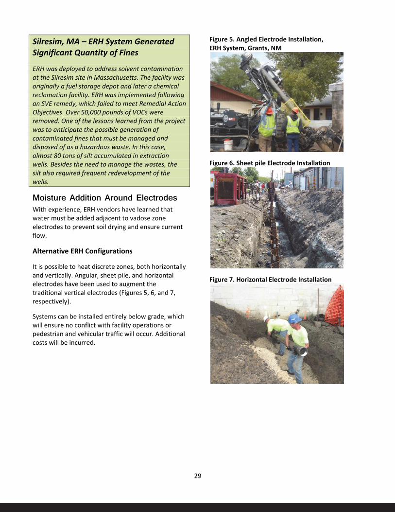
29
Silresim, MA – ERH System Generated Significant Quantity of Fines
ERH was deployed to address solvent contamination at the Silresim site in Massachusetts. The facility was originally a fuel storage depot and later a chemical reclamation facility. ERH was implemented following an SVE remedy, which failed to meet Remedial Action Objectives. Over 50,000 pounds of VOCs were removed. One of the lessons learned from the project was to anticipate the possible generation of contaminated fines that must be managed and disposed of as a hazardous waste. In this case, almost 80 tons of silt accumulated in extraction wells. Besides the need to manage the wastes, the silt also required frequent redevelopment of the wells.
Moisture Addition Around Electrodes With experience, ERH vendors have learned that water must be added adjacent to vadose zone electrodes to prevent soil drying and ensure current flow.
Alternative ERH Configurations
It is possible to heat discrete zones, both horizontally and vertically. Angular, sheet pile, and horizontal electrodes have been used to augment the traditional vertical electrodes (Figures 5, 6, and 7, respectively).
Systems can be installed entirely below grade, which will ensure no conflict with facility operations or pedestrian and vehicular traffic will occur. Additional costs will be incurred.
Figure 5. Angled Electrode Installation, ERH System, Grants, NM
Figure 6. Sheet pile Electrode Installation
Figure 7. Horizontal Electrode Installation

30
Selection and Sizing of Off-Gas Treatment Equipment Proper specification and sizing of off-gas treatment components is critical.
• For many contaminants, volatilization and recovery are the primary treatment mechanisms.
• At sites with significant contamination, recoveries will also be significant.
• Contaminant volume and GAC compatibility will determine whether GAC or some other form of recovery and treatment such as thermal oxidation are appropriate.
• Contaminant recoveries must be carefully monitored to ensure that the capacities of off-gas systems are not exceeded.
Alhambra, CA Non-NPL wood treater
At the Alhambra wood treater TCH project, it was necessary to temporarily reduce energy input to a portion of the subsurface. A spike in contaminant concentrations in the off-gas from a previously unknown ‘hot spot’ threatened to exceed the heat capacity of the regenerative thermal oxidizer. An estimated one million pounds of contaminant mass was recovered and/or destroyed during the project.
Site Preparation and Remedy Installation Site preparation requirements vary depending on the type of ISTT to be implemented and site characteristics, but may include:
• Removing or replacing monitoring wells constructed of materials unable to withstand target treatment temperatures (such as polyvinyl chloride [PVC]).
• Protection, relocation, or removal of subsurface utilities, which may be adversely impacted by ISTT operation or construction activities.
• Site grading to promote positive drainage away from the treatment area; this is especially important for sites where the target treatment zone may begin less than five feet from the native ground surface.
• Coordination and installation of utility feeds necessary to operate the ISTT system and supporting infrastructure.
• Installation of a surface cap, if a cap is being used for the application.
• In SEE applications, wells and historical soil borings within the steam injection zones are often abandoned by over drilling and grouted with high temperature cement to eliminate the potential for steam venting to the ground surface. Bentonite-based grout is subject to desiccation under elevated temperature and pressure conditions associated with SEE. Plastic wells and bentonite can be problematic for ERH and TCH as well.
• Installing barriers such as interception trenches or physical barriers (soil-bentonite slurry or sheet pile) to hydraulically isolate the treatment zone.
Well field components, including heater wells, electrodes, steam injection wells, temperature and pressure sensors, and multiphase extraction wells (for combined or independent vapor and groundwater recovery), are installed following site preparation activities. Conventional drilling methods are commonly used for these features. Heater wells used in TCH systems can sometimes be driven using pile driving equipment, resulting in cost savings. ERH electrodes have been constructed using driven metal sheet piles.
Waste Generation during System Installation Well field installation usually results in the generation of significant quantities of potentially contaminated soil cuttings from drilling activities, such as occurs when using hollow stem augers. Since large borings are often required for ERH electrode construction, sonic drilling methods are frequently applied to minimize cutting generation. Sonic drilling or other direct push methods are typical for TCH heaters, which do not require large-diameter borings.
Strategies for heating system installation that do not generate cuttings (such as driven heaters or sheet piles) may be advantageous to consider should site conditions allow. Procedures for segregating site soils into hazardous and potentially non-hazardous soils under the RCRA contained-in policy should be considered. At one site, contaminated soil cuttings were consolidated beneath an insulated cap within

31
the target treatment zone for treatment by ISTT, avoiding the need for offsite disposal of the cuttings.
Refining the Conceptual Site Model during Remedy Installation During installation of well field components, logging of each boring is often not conducted. However, it may be appropriate to log the borings of a subset of the well field components to confirm that geologic conditions are as assumed during the design and to look for differing subsurface conditions that could affect ISTT performance.
It may be advisable to screen for contamination levels at the outer row of boreholes being installed. Detection of high levels of contamination may indicate the need to expand the TTZ.
With ERH and TCH systems, the electrode and heater well installation is often on a tighter spacing than monitoring wells and/or sampling borings that were installed, allowing for better definition of subsurface conditions.
System Layout System piping (such as fluid conveyance lines and manifolds) is typically placed on grade or supported with portable pipe stands; heating system power cables, communication, and control cables are frequently placed directly on the ground surface. As discussed in the ISTT System Design section, a number of ISTT systems have been installed entirely below grade.

32
ISTT System Operations and MonitoringSystem Startup Once all subgrade heating equipment, vapor recovery and treatment, and temperature and pressure monitoring components are commissioned and deemed fully operational, ISTT system startup generally commences with the extraction of soil vapor and groundwater (if groundwater extraction is to be employed) with the heating system off. When adequate pneumatic and hydraulic containment are verified through field measurements, site heating is initiated. Heating strategies vary among ISTT vendors and are a function of individual site characteristics. With ERH, the amount of power applied per foot of electrode may vary during startup or heat-up, with some electrodes receiving more or less power than others. With TCH, a single heater well typically is installed across the entire target heated interval and power is applied relatively uniformly across the entire heater well, although electrical heater elements can be fabricated so as to deliver more watts per foot at the bottom and/or top segments if desired (known as "boosting").
With increasing subsurface temperature, target site contaminants will begin to be mobilized. Areas surrounding heaters or electrodes are the first to achieve treatment temperatures. In general, site heat-up is often achieved within approximately 60-90 days of active heating (Figure 8). The figure shows temperatures measured by thermocouples at eight areas within the TTZ.
At many sites, the subsurface will not heat uniformly or precisely as predicted by thermal modeling that may have been conducted as part of the ISTT system design. As sites are heated, distinct thermal signatures, as measured by the temperature monitoring systems, are often produced. For ERH and TCH systems, portions of the aquifer through which faster groundwater flow occurs may heat more slowly than other zones, as some of the heat delivered to those zones is transported out of the treatment zone via groundwater flow.
Figure 8. Subsurface Temperature Increase After ISTT Startup, Dunn Field Site
Source: Heron, 2009
For ERH systems, non-uniform heating patterns may also be due to variations in soil electrical conductivity that result in non-uniform flow of electrical current.
For SEE, hydraulic conductivity will largely control initial heating patterns at the site.
33
When target temperatures greater than the boiling point of water are specified to address contaminants such as PAHs, PCBs, and dioxins, thermal conductive heating will be required. For such sites, TCH follows a three phase regime: Phase 1 involves heating the subsurface to the boiling point of water, Phase 2 involves a temperature plateau at approximately 100ºC while water is boiled off, and Phase 3 involves resumed temperature increase to reach and maintain the target temperature.
Monitoring The general categories of operational, performance, and compliance monitoring are common to any remedial technology. Parameters specific to ISTT are described below.
Operational Monitoring involves monitoring system parameters and subsurface conditions indicative of proper operation.
Temperature is the operating parameter of interest in the first few weeks of ISTT. Temperature is monitored via appropriately located thermal monitoring devices —generally at the centroid of electrode or heater arrays (the location where achievement of requisite temperatures should be the most difficult). Contaminant recovery rates increase and peak as the temperature increases through the VOC boiling point and these extraction rates take on the greatest interest. After the peak extraction rate, attention shifts to direct measures of soil and groundwater concentrations.
While achieving and maintaining a target temperature is the objective, temperature is in some ways a “trailing indicator” of performance. Vendors report that they closely monitor energy input, a leading indicator of system performance. Pressure monitors are also used to ensure necessary pneumatic and hydraulic control during ISTT operations
Temperature data is typically monitored electronically in real time to allow rapid assessment of heating progress and to document that target temperatures are achieved.
ISTT systems typically use both manual (site operator) and automated measurements to assess
equipment performance. ISTT vendors frequently monitor certain system operation parameters, such as thermocouple data, remotely. However, many ISTT systems require an onsite operator to be present for at least part of the day when operating to accomplish critical operational activities.
Performance Monitoring involves monitoring parameters indicative of progress toward achievement of ISTT system performance objectives.
The mass of COCs recovered through operation of the ISTT system is tracked using both quantitative and qualitative methods. The groundwater and vapor extraction rates and associated COC concentration are measured using field instruments (such as a PID), and periodically via samples sent to a fixed-base (offsite) laboratory. The consumption of caustic by thermal oxidizers used in off-gas treatment of chlorinated compounds is also used for estimating mass removal rates since the rate of caustic consumption is generally proportional to rate of halogenated compound destruction (Figure 9).
Compliance Monitoring Compliance monitoring involves: 1) monitoring for compliance with regulatory requirements and public health related concerns; and 2) demonstration of achievement of performance objectives. Depending on the contaminants of concern and the quantities expected to be recovered and /or treated, local regulations may specify limits for air emissions and water discharges.
ISTT project beneath or adjacent to inhabited spaces are likely to be subject to ambient indoor air limits for COCs.
In the case of ERH, the OSHA standard for step potential is 50 volts. ERH vendors report a practice of not exceeding 12 volts at the surface.
System Adjustments Vendors will make frequent/periodic adjustments throughout the course of the heating campaign. Adjustments are likely to be more frequent than is

34
generally the case for SVE or Pump and Treat systems, which may operate for extended periods of
time with limited adjustment. Flexible, adaptive implementation is key to project success.
Figure 9. PID Reading on Extracted Vapors, Mass Removed in Vapor Phase, Dunn Field Site
As zones achieve cleanup objectives as indicated by the results of hot sampling and recovered vapor concentrations, power can be shifted from those zones to zones which are not cleaning up as rapidly.
Installation of additional electrodes or heater wells is feasible, but adds cost. As would be expected, installing equipment in an existing ISTT field is more complex than initial ISTT system installation.
Data Management/ Communications Many ISTT projects utilize data telemetry and web-based tools to facilitate site management and team communications. Site-specific web sites are increasingly prevalent.
Data on system operations, temperature distribution and daily and cumulative contaminant destruction and/or recovery can be uploaded in a timely manner for consideration by all interested parties.
ISTT System Closure Confirmatory Sampling Hot sampling procedures are available to allow mid-course corrections as well as to determine the ultimate achievement of performance objectives.
Subsurface temperatures remain elevated for an extended period of time following ISTT operations. With some local variability, sites generally cool at a rate of approximately 1ºC per day (Figure 10). It would obviously be undesirable to have ISTT equipment on standby, incurring daily charges waiting for the site to return to ambient conditions. Hot sampling procedures (citation) allow timely confirmatory performance sampling while controlling for the possible loss of VOCs, which would otherwise give an inaccurate indication of ISTT performance.

35
Figure 10. Hot soil core being cooled in ice bath, Grants, NM
Hot sampling can also supplement temperature and power distribution data to allow discontinuation of heating of zones that have met cleanup goals, allowing power to be concentrated in zones not cleaning up as quickly.
Health and Safety considerations require close coordination between sampling contractors and ISTT vendors. Hot sampling may require temporary discontinuation of heating.
Infrastructure Abandonment Following completion of ISTT activities, surface equipment will be demobilized from the site, frequently for subsequent reuse. Common practice is to abandon subsurface equipment in place, subject to local jurisdiction requirements for proper abandonment.
36
Miscellaneous Considerations
Site Security Security measures and perimeter monitoring are generally necessary both for safety of unauthorized personnel and to prevent theft. The presence of materials in the treatment zone that have significant salvage value (such as heavy copper cables used to convey power) may create tempting targets for theft. Security measures may include the use of fencing equipped with signs warning against entry, as well as video cameras or motion sensors that trigger alarms and/or system shutdown.
Subsidence Subsidence occurs when drying of the subsurface results in desiccation and shrinkage. Subsidence can be of concern when ISTT occurs beneath structures and can also affect installed ISTT systems.
Subsidence has generally not been a problem for ISTT projects for a number of reasons including the fact that heating often occurs at depth and the degree of moisture reduction does not result in sufficient desiccation to cause subsidence.
Based on the Camelot Cleaners experience, subsidence may need to be considered at sites with significant clay content in near surface zones which will be subject to ISTT.
Byproducts Post-treatment monitoring may indicate the presence of some chemicals in groundwater that were not present prior to thermal treatment. For sites at which soil contains a higher percentage of organic content, heating can produce acetone and other water soluble organic compounds (Beyke and Fleming, 2005). Acetone is a known product of peat
and is often measured at ambient temperatures at peat sites. Heat accelerates peat decomposition. Sites may exhibit elevated concentration of this compound in groundwater during and following thermal treatment operations. Byproducts are generally transient and short-lived.
Camelot Cleaners, Fargo, ND – ERH Subsidence
The Camelot site is the only known site where appreciable subsidence has occurred as a result of ISTT application. Soils in the treatment area, which were covered by a temporary treatment building to protect against freezing of pipes, showed evidence of subsidence up to 18 inches. The cause was either due to moisture loss during the thermal treatment or to a lack of soils compaction after demolition of the dry cleaners building, or some combination thereof. The clays at the site were expansive-type Smectite clays which are much more subject to shrink/swell than other types of clays.
The temporary treatment building, which had a post-frame or pole barn design, required considerable shoring with jacks in the final months of the treatment to prevent collapse. Fortunately, a nearby residence did not experience subsidence issues beyond normal freeze-thaw cycles, based on data collected from extensometers attached to the house during the thermal treatment.
Silresim, MA – ERH Byproducts
At the Silresim Superfund Site (Region 2), acetone concentration increased by nearly 1,000 fold in groundwater monitoring wells following ISTT system operation (Davis, 2007).

37
Attachment A – List of RPMs/OSCs/STLs Contacted Site EPA Contact
Groveland Wells, MA Derrick Golden, RPM, EPA Region 1
Silresim, MA Dan Keefe, RPM, EPA Region 1
SRSNE, CT Karen Lumino, RPM EPA Region 1 Steve Mangion, ORD Superfund and Technology Liaison (STL)(Retired)
Camelot Cleaners, ND Joyce Ackerman, OSC, EPA Region 8
Grants Solvents, Grants, NM Sairam Appaji, RPM EPA Region 6
Pemaco, Maywood, CA Rose Marie Caraway, RPM EPA Region 9
Frontier Fertilizer, CA Bonnie Arthur, RPM EPA Region 9
Ft. Lewis, WA Kira Lynch, RPM EPA Region 10 (now STL)

38
Attachment B – Reviewers Dr. Eva Davis – ORD/Ada, Ok
Linda Fiedler – OSRTI
Katherine Garufi – OSRTI
Michelle Kerr – EPA Region 5