issue no. 2, apr-jun
TRANSCRIPT
A SERVICE PUBLICATION OFLOCKHEED AERONAUTICALSYSTEMS COMPANY
Editor
Charles I. Gale
Art DirectorCathy E. Howard
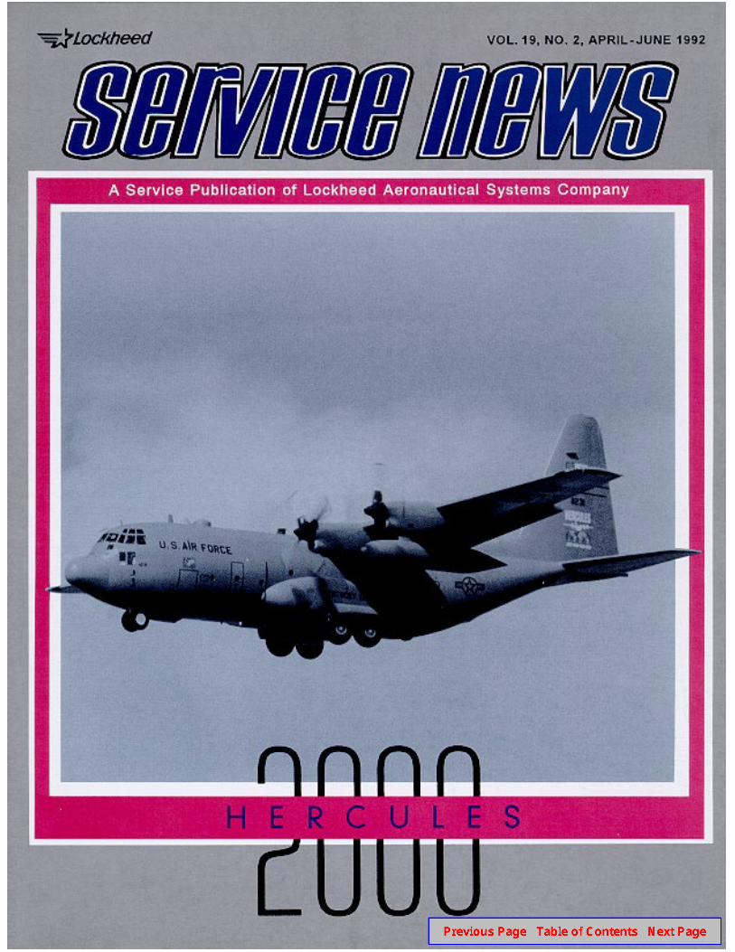
Vol. 19, No. 2, April-June 1992
2 Focal PointNow at ship 2000 and counting, theHercules boasts a proud pedigree.
3 Fuel Quantities UpdateThe main fuel tank capacity valuesgiven in most of the manuals needupdating. Here are the new figures.
8 Instrumentation Test SetThis multipurpose tester willsatisfy today’s stringent accuracyand capability requirements.
10
12
A New Generator ControlUnit for the HerculesAn updated system offers greaterreliability, easier maintenance,and higher-quality electrical power.
Simulated Engine-Out ControlSpeedsEngine-out simulations involvecontrollability factors that deserveclose study and attention.
Photographic Support: John Rossino
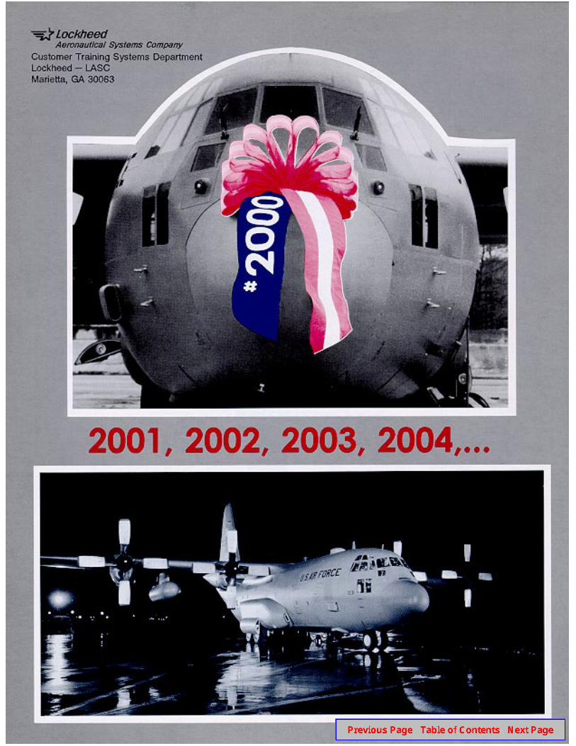
Covers: Our front cover shows the2000th Hercules aircraft during a testflight. The ground shots on the backcover offer some additional views of thehistoric aircraft shortly before it wasdelivered to the Kentucky Air NationalGuard on May 15, 1992.
Ship 2000! The Line Breeds TrueFew who witnessed the inaugural flights of the early C-l 30A Hercules aircraft
in the spring of 1955 could ever have imagined it. The very first airplane to roll offthe assembly line is still in service and earning its keep 37 Years later. Most wouldhave been even more incredulous had they been told that the production lineturning out the gleaming new turboprops would also still be earning its keep nearlyfour decades later. And in championship style! In May of this Year, the Lockheedproduction facility in Marietta, Georgia, proudly delivered its 2000th Hercules. It isappropriate that the new owner should be the Kentucky Air National Guard.Today’s Hercules, an up-dated and much improvedversion of the original, is athoroughbred in every senseof the word.
There is nothing in thehistory of aviation that evenremotely matches the recordof the Hercules aircraft. Longthe mainstay of both militaryand commercial airlift aroundthe world, the Hercules hasbeen in continuous prod-uction for more than a thirdof the time since the Wrightbrothers taught the worldhow to fly.
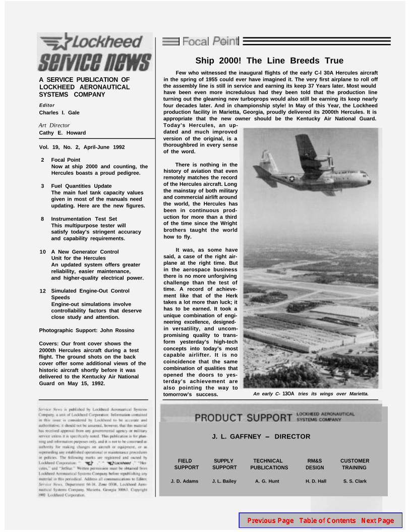
It was, as some havesaid, a case of the right air-plane at the right time. Butin the aerospace businessthere is no more unforgivingchallenge than the test oftime. A record of achieve-ment like that of the Herktakes a lot more than luck; ithas to be earned. It took aunique combination of engi-neering excellence, designed-in versatility, and uncom-promising quality to trans-form yesterday’s high-techconcepts into today’s mostcapable airlifter. It is nocoincidence that the samecombination of qualities thatopened the doors to yes-terday’s achievement arealso pointing the way totomorrow’s success. An early C- 13OA tries its wings over Marietta.
J. L. GAFFNEY - DIRECTOR
FIELD SUPPLY TECHNICAL RM&S CUSTOMERSUPPORT SUPPORT PUBLICATIONS DESIGN TRAINING
J. D. Adams J. L. Bailey A. G. Hunt H. D. Hall S. S. Clark
Fuel Quantities Update
by W. G. Moses, Aircraft Structures Engineer, SeniorLASC Aeromechanics Department
R ecent studies conducted by the U.S. Air Force andLockheed have shown that the fuel capacity values
given for the Hercules aircraft in much of the authorizeddocumentation need to be updated. Operational Supple-ment T.O. lC-130B-IS-263 already reflects some ofthese changes as they apply to USAF airplanes.
The tables that accompany this article offer abroader selection of data and include the correct capaci-ties for all tanks installed in the more prevalent configu-rations of the airplane. Note that the values shown in thetables for external tanks are for the Lear Siegler PN305JOOl units, the type currently being installed in newproduction Hercules aircraft. Other kinds of externaltanks will have different unusable and usable fuelvolumes and weights.
The new fuel volumes apply to aircraft Lockheedserial number LAC 4542 and up, and to earlier airplaneswhich have had their outer wings replaced with eitherFY ‘73 (LAC 4542) or FY ‘84 (LAC 4992)-type outerwings. Modifications to improve the outer wing struc-ture and update the fuel system have contributed to thechanges in fuel capacities of the main tanks. The chang-es amount to a reduction of approximately 3.5% in thecapacities of these tanks. The fuel quantity indicatingsystem is not directly involved. Careful checking hasdetermined that its accuracy is well within the limitsrequired by thespecification. Further studies to establishthe overall effects of the fuel quantity changes on theairframe are in progress.
Establishing the New Values
The Lockheed tests to establish current total fuelcapacities were conducted on two new Hercules air-planes on initial fueling after rollout. These aircraftwere selected as typical baseline airplanes, and were notequipped with either refueling pods or explosion-sup-pressant foam. The total capacities in volume and weightobtained from these studies are shown in Table 1. Noattempt was made to confirm or revise the unusable fuelvolumes in these tests. The tables thus show the existingunusable fuel volumes, which have been retained, andthe resulting usable fuel volumes. JP-4 and JP-5 understandard-day conditions were used as the bases for theweight calculations.
Table 2 shows fuei capacities for non-USAF Hercu-les aircraft equipped with refueling pods but no foam.Table 3 contains the volumes and weights for USAFaircraft equipped with foam. For these USAF aircraft,the total fuel figure should be understood to mean the
total capacity minus the fuel that is displaced by the dryfoam. Table 4 shows the corresponding values forUSAF C-130 airplanes equipped with refueling pods.The effects of foam on tank capacities were determinedby Warner Robins Air Logistics Center.
Unusable Fuel - Two Standards
The tables show two sets of unusable fuel volumesfor airplanes without foam. Both are in current use. Thedifferences between them arise from differences in theway the numbers have been derived. The first set ofvalues are those employed by the USAF. These volumesfor unusable fuel are the same as originally used for C-130B and C-130E models. The usable fuel volumes forairplanes with foam in the tanks apply only to USAFHercules aircraft.
The other set of figures show the unusable fuelvolumes that have been certified by the FAA for civilmodels of the Hercules. These values are also used formilitary models, except for those operated under USAFtechnical orders. The resulting usable fuel volumes arethus applicable to most non-USAF Hercules aircraft.
Reviewing the Structural-Limit Fuel Weights
It should be noted that the full-fuel weights shownin the tables for JP-4 (6.5 pounds per gallon) continue todefine structural-limit fuel weights for aircraft with hardstruts. Similarly, the full-fuel weights shown for JP-5(6.8 pounds per gallon) are the structural-limit fuelweights for aircraft equipped with soft struts. Since themain tank volumes are reduced, it might be supposedthat a fuel with higher density could be used to producethe same allowable fuel weights as previously employed.Unfortunately, this is not the case.
The purpose of the new outer wing designs was tooffer enhanced fatigue resistance in critical areas andincorporate improvements to the fuel system. Althoughthe changes resulted in a better outer wing, some weightwas added in the process. Design requirements result ina total weight limit for the outer wing which is the sumof the structural, system, and fuel weights. The decreasein fuel capacity, in effect, compensates for the increasedweight of the empty wing. Substituting a fuel with ahigher density to offset the reduced volume would there-fore not be appropriate and, if used, could lead torestrictions for ground operation of the airplane.
Lockheed SERVICE NEWS V19N2
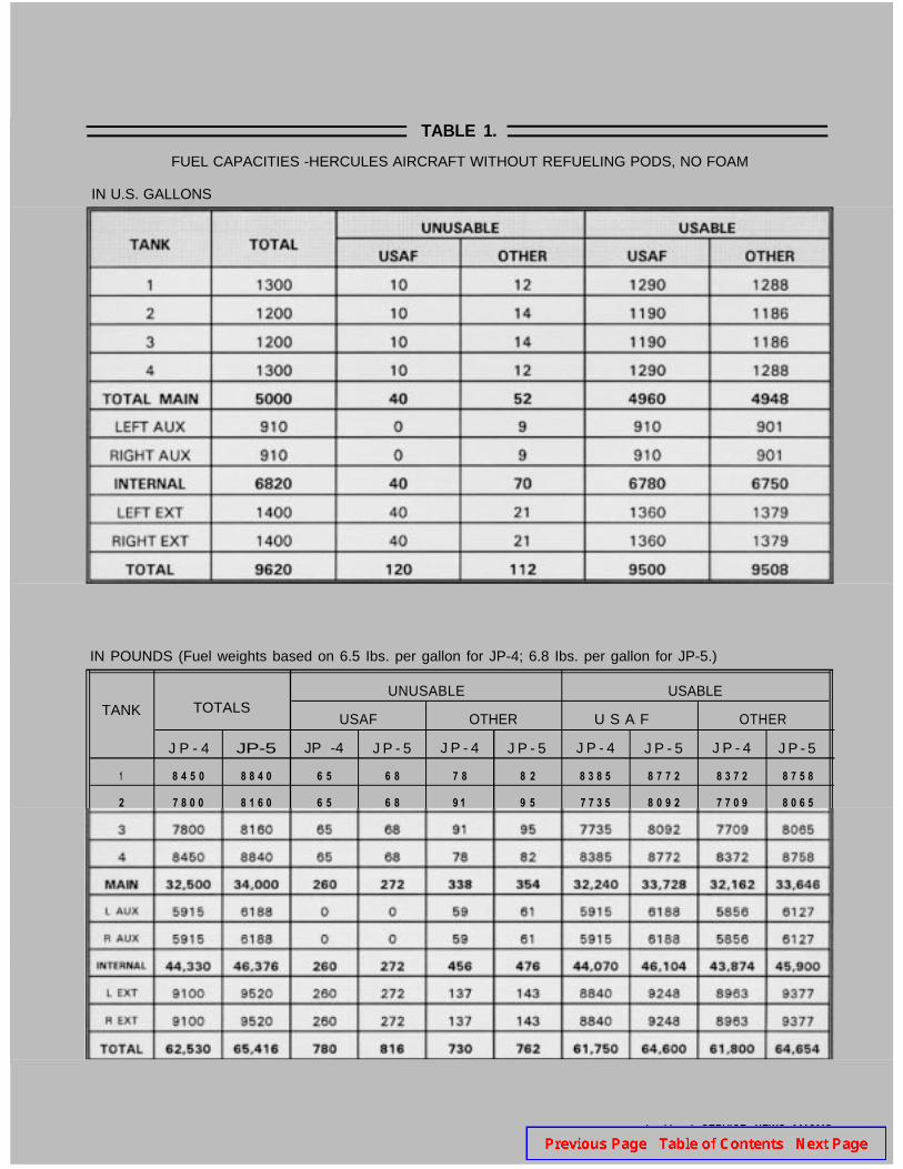
TABLE 1.
FUEL CAPACITIES -HERCULES AIRCRAFT WITHOUT REFUELING PODS, NO FOAM
IN U.S. GALLONS
IN POUNDS (Fuel weights based on 6.5 Ibs. per gallon for JP-4; 6.8 Ibs. per gallon for JP-5.)
UNUSABLE USABLETANK TOTALS
USAF OTHER U S A F OTHER
J P - 4 JP-5 JP -4 J P - 5 J P - 4 J P - 5 J P - 4 J P - 5 J P - 4 J P - 5
1 8 4 5 0 8 8 4 0 6 5 6 8 7 8 8 2 8 3 8 5 8 7 7 2 8 3 7 2 8 7 5 8
2 7 8 0 0 8 1 6 0 6 5 6 8 9 1 9 5 7 7 3 5 8 0 9 2 7 7 0 9 8 0 6 5
Lockheed SERVICE NEWS V19N2
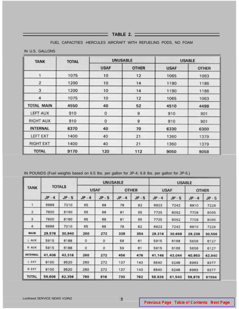
TABLE 2.
FUEL CAPACITIES -HERCULES AIRCRAFT WITH REFUELING PODS, NO FOAM
IN U.S. GALLONS
IN POUNDS (Fuel weights based on 6.5 Ibs. per gallon for JP-4; 6.8 Ibs. per gallon for JP-5.)
Lockheed SERVICE NEWS V19N2
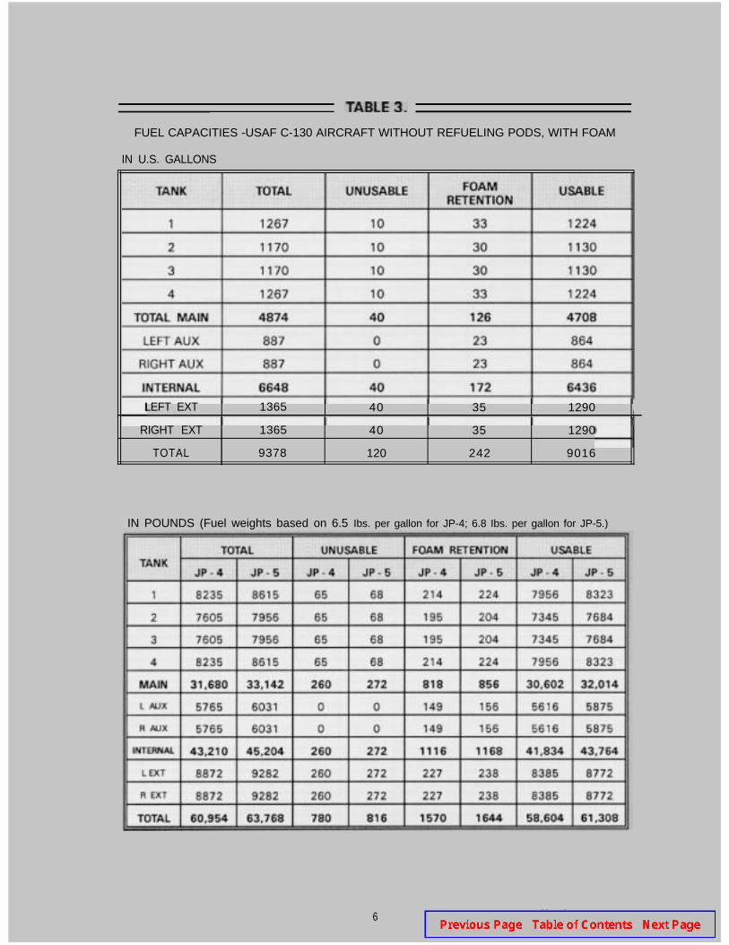
FUEL CAPACITIES -USAF C-130 AIRCRAFT WITHOUT REFUELING PODS, WITH FOAM
IN U.S. GALLONS
LEFT EXT 1365 40 35 1290I
RIGHT EXT 1365 40 35 1290
TOTAL 9378 120 242 9016
IN POUNDS (Fuel weights based on 6.5 Ibs. per gallon for JP-4; 6.8 Ibs. per gallon for JP-5.)
6 Lockheed SERVICE NEWS V19N2
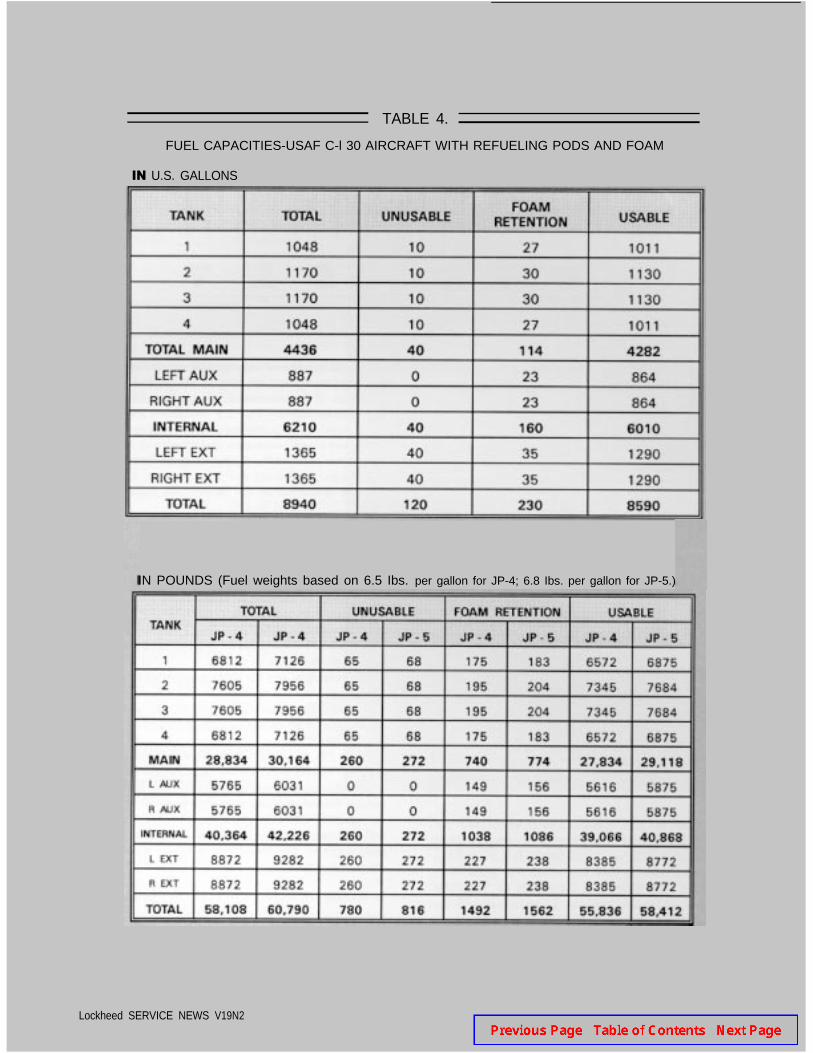
TABLE 4.
FUEL CAPACITIES-USAF C-l 30 AIRCRAFT WITH REFUELING PODS AND FOAM
IN U.S. GALLONS
IN POUNDS (Fuel weights based on 6.5 Ibs. per gallon for JP-4; 6.8 Ibs. per gallon for JP-5.)
Lockheed SERVICE NEWS V19N2
S E
by William C. Turbyfield, Electronics Engineer, SeniorElectronic Support Equipment Engineering Department
T he functionality and mobility requirements de-manded by today’s military and commercial avia-
tion communities have created unique problems withregard to test equipment. The equipment used to testaircraft components must be versatile, easily transport-able, and reliable. At the same time, it must also be ableto meet the broad spectrum of accuracy and capabilitystandards set by maintenance organizations.
Individual pieces of single-function equipmentdesigned to check specific components may have beenacceptable in the past, but the realities of today’s aero-space maintenance environment are dictating new levelsof applicability and performance. There is a real needfor a single, lightweight package that will combinemultiple testing capabilities.
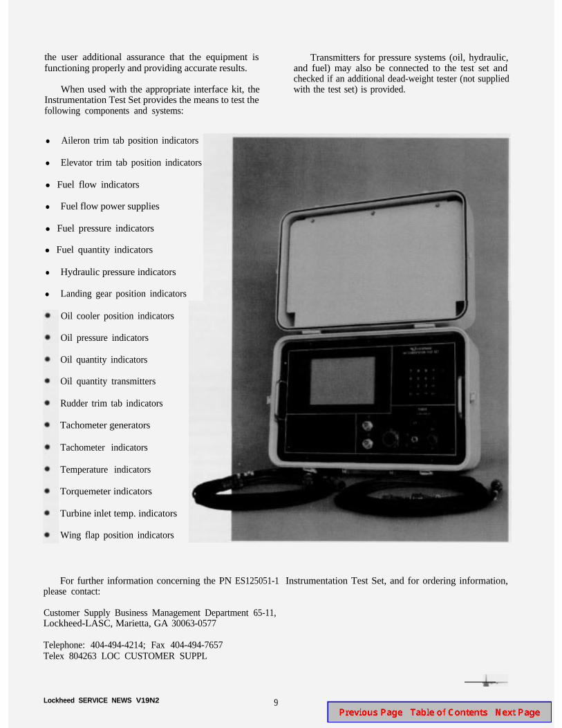
At Lockheed Aeronautical Systems Company, weare meeting this challenge by building a unique, newgeneration of test equipment. One outstanding productthat has resulted from this effort is the portable, practi-cal, and highly reliable PN ES125051-1 InstrumentationTest Set.
This test set is a versatile and powerful unit de-signed to test aircraft instrumentation components atorganizational, field, and depot levels. It is housed in arugged, transportable case that offers true portability.This allows easy transfer of the unit to the particularrepair shop where it is required. When teamed with thePN ES125052-( ) Interface Kit that contains the adapt-ers and cables appropriate to the instrumentation beingchecked, the test set is capable of functionally testing animpressive variety of indicators and associated transmit-ters .
8
To be considered truly mobile and multifunctional,test equipment must be easy to set up and require aminimum of documentation to operate and maintain.The Instrumentation Test Set establishes standards ofperformance in this category. All circuitry for simu-lating instrument parameters and measuring transmitteroutputs are contained in the test set itself. Instructions tothe operator, pull-down and pop-up menus, and on-linehelp are displayed on the built-in flat-panel graphicsdisplay.
Operator input is provided through use of the testset’s numeric key pad. Depending on the unit under test,selected values of simulated parameters are presented onthe display in an easy-to-read format, as are the mea-sured values of transmitter outputs.
The software routines necessary to adapt the unit forthe particular instrumentation systems to be checked areloaded into the tester by the use of external cartridges.These cartridges and the cable assemblies required forinterfacing with the capabilities that will be tested arecontained in separate kits. This allows each user toconfigure the test set for his particular needs.
The PN ES125052-1 Interface Kit, which allowstesting of Hercules aircraft instrumentation components,is available now. However, provision has been made toexpand the test set to accommodate new instrumentationas required. Other interface kits for different aircraftwill become available as needed to meet customerrequirements. This will greatly increase the tester’svalue over time.
In addition to being easy to use and expandable, thetest set also offers outstanding dependability. Includedamong its features are built-in self-test and calibrationprocedures that ensurehigh reliability. Simulated signalsfrom the test set are looped back to monitor circuitry,permitting an internal test of the equipment’s operationand accuracy. This type of self-testing capability gives
Lockheed SERVICE NEWS V19N2
the user additional assurance that the equipment isfunctioning properly and providing accurate results.
When used with the appropriate interface kit, theInstrumentation Test Set provides the means to test thefollowing components and systems:
l Aileron trim tab position indicators
l Elevator trim tab position indicators
l Fuel flow indicators
l Fuel flow power supplies
l Fuel pressure indicators
l Fuel quantity indicators
l Hydraulic pressure indicators
l Landing gear position indicators
Oil cooler position indicators
Oil pressure indicators
Oil quantity indicators
Oil quantity transmitters
Rudder trim tab indicators
Tachometer generators
Tachometer indicators
Temperature indicators
Torquemeter indicators
Turbine inlet temp. indicators
Wing flap position indicators
Transmitters for pressure systems (oil, hydraulic,and fuel) may also be connected to the test set andchecked if an additional dead-weight tester (not suppliedwith the test set) is provided.
For further information concerning the PN ES125051-1 Instrumentation Test Set, and for ordering information,please contact:
Customer Supply Business Management Department 65-11,Lockheed-LASC, Marietta, GA 30063-0577
Telephone: 404-494-4214; Fax 404-494-7657Telex 804263 LOC CUSTOMER SUPPL
Lockheed SERVICE NEWS V19N2 9
A New GeneratoControl Unitfor the
erculesby Larry Arnold, Staff EngineerC-130/L-100 Electrical Design Group
T he electrical power system of the Hercules airlifterhas recently been updated to provide the aircraft
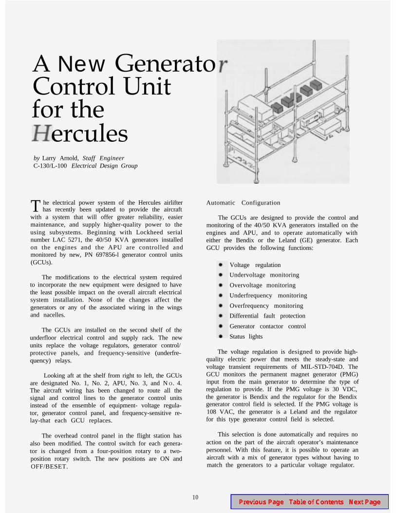
with a system that will offer greater reliability, easiermaintenance, and supply higher-quality power to theusing subsystems. Beginning with Lockheed serialnumber LAC 5271, the 40/50 KVA generators installedon the engines and the APU are controlled andmonitored by new, PN 697856-l generator control units(GCUs).
The modifications to the electrical system requiredto incorporate the new equipment were designed to havethe least possible impact on the overall aircraft electricalsystem installation. None of the changes affect thegenerators or any of the associated wiring in the wingsand nacelles.
The GCUs are installed on the second shelf of theunderfloor electrical control and supply rack. The newunits replace the voltage regulators, generator control/protective panels, and frequency-sensitive (underfre-quency) relays.
Looking aft at the shelf from right to left, the GCUsare designated No. 1, No. 2, APU, No. 3, and NO. 4.The aircraft wiring has been changed to route all thesignal and control lines to the generator control unitsinstead of the ensemble of equipment- voltage regula-tor, generator control panel, and frequency-sensitive re-lay-that each GCU replaces.
The overhead control panel in the flight station hasalso been modified. The control switch for each genera-tor is changed from a four-position rotary to a two-position rotary switch. The new positions are ON andOFF/BESET.
Automatic Configuration
The GCUs are designed to provide the control andmonitoring of the 40/50 KVA generators installed on theengines and APU, and to operate automatically witheither the Bendix or the Leland (GE) generator. EachGCU provides the following functions:
Voltage regulation
Undervoltage monitoring
Overvoltage monitoring
Underfrequency monitoring
Overfrequency monitoring
Differential fault protection
Generator contactor control
Status lights
The voltage regulation is designed to provide high-quality electric power that meets the steady-state andvoltage transient requirements of MIL-STD-704D. TheGCU monitors the permanent magnet generator (PMG)input from the main generator to determine the type ofregulation to provide. If the PMG voltage is 30 VDC,the generator is Bendix and the regulator for the Bendixgenerator control field is selected. If the PMG voltage is108 VAC, the generator is a Leland and the regulatorfor this type generator control field is selected.
This selection is done automatically and requires noaction on the part of the aircraft operator’s maintenancepersonnel. With this feature, it is possible to operate anaircraft with a mix of generator types without having tomatch the generators to a particular voltage regulator.
10 Lockheed SERVICE NEWS V19N2
System Monitoring
Each GCU also provides system monitoring of thegenerator output and controls the contactor which tiesthe generator to the aircraft loads. If any of the moni-tored parameters are outside the design limits, thegenerator contactor will be deenergized and the GENOUT light illuminated. In some cases, the generator willalso be deenergized. System monitoring includes:
1. UNDERVOLTAGE - If voltage drops to 95 VACor below for more than 4 seconds, the line contactorwill open, the generator will deenergize, and theGEN OUT light will illuminate. The generator canbe reset by placing the control switch toOFF/RESET and then back to ON.
2. OVERVOLTAGE - When voltage exceeds an in-verse time curve of 5 volt-seconds above 130 VAC,up to a maximum of 190 VAC, the line contactorwill open, the generator will deenergized, and theGEN OUT light will illuminate. The generator canbe reset by placing the control switch toOFF/RESET and then back to ON.
3. UNDERFREQUENCY - If the frequency dropsbelow 365 Hertz, the line contactor will open andthe GEN OUT light will illuminate. When frequen-cy rises above 375 Hertz, the line contactor willclose and the light will go out.
4. OVERFREQUENCY - If the frequency exceeds440 Hertz, the line contactor will open and the GENOUT light will illuminate. When the frequencydrops to 430 Hertz, the contactor closes and thewarning light will go out.
5. DIFFERENTIAL FAULT - If the difference be-tween the current at the generator terminals and thecurrent at the contactor terminals exceeds 35 amps,indicating a feeder fault, the line contactor willopen, the generator will deenergize, and the GENOUT light will illuminate. The GCU cannot be resetafter detecting a differential fault until all powersources are removed from the GCU.
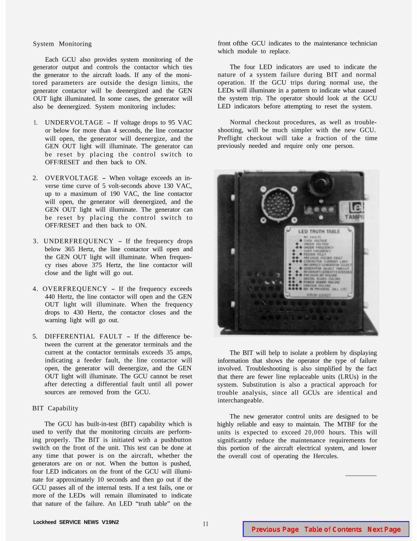
BIT Capability
The GCU has built-in-test (BIT) capability which isused to verify that the monitoring circuits are perform-ing properly. The BIT is initiated with a pushbuttonswitch on the front of the unit. This test can be done atany time that power is on the aircraft, whether thegenerators are on or not. When the button is pushed,four LED indicators on the front of the GCU will illumi-nate for approximately 10 seconds and then go out if theGCU passes all of the internal tests. If a test fails, one ormore of the LEDs will remain illuminated to indicatethat nature of the failure. An LED “truth table” on the
Lockheed SERVICE NEWS V19N2
front ofthe GCU indicates to the maintenance technicianwhich module to replace.
The four LED indicators are used to indicate thenature of a system failure during BIT and normaloperation. If the GCU trips during normal use, theLEDs will illuminate in a pattern to indicate what causedthe system trip. The operator should look at the GCULED indicators before attempting to reset the system.
Normal checkout procedures, as well as trouble-shooting, will be much simpler with the new GCU.Preflight checkout will take a fraction of the timepreviously needed and require only one person.
The BIT will help to isolate a problem by displayinginformation that shows the operator the type of failureinvolved. Troubleshooting is also simplified by the factthat there are fewer line replaceable units (LRUs) in thesystem. Substitution is also a practical approach fortrouble analysis, since all GCUs are identical andinterchangeable.
The new generator control units are designed to behighly reliable and easy to maintain. The MTBF for theunits is expected to exceed 20,000 hours. This willsignificantly reduce the maintenance requirements forthis portion of the aircraft electrical system, and lowerthe overall cost of operating the Hercules.
11
Flight Characteristics and Performance:
by M. A. DeCastro Jr., Senior EngineerProduct and System Safety Engineering Department
W hich of the following situations will produce thehighest minimum speeds at which the aircraft can
be controlled ?
l No. 1 engine failed, propeller feathered.
l No. 1 engine failed, propeller windmilling.
No. 1 engine simulated out, throttle at flight idle.
Under certain conditions, the engine-out simulationwill require higher speeds to maintain directional controlthan either of the other situations. Since simulatedengine-out approaches and landings are an almost dailyoccurrence, it is important for Hercules flight crews tobe thoroughly familiar with this characteristic and whatcan be done to prevent potential problems in the trafficpattern.
Minimum Control Speed-Air (Vmca)
The Vmca for an aircraft is the minimum speed atwhich the pilot can maintain control and continuestraight flight. It is a precisely defined value that isdetermined by flight test and based on a set of constantconditions. In the case of the Hercules aircraft, the Vmca
constants for one-engine failures are as follows:
Maximum power on the operating engines.
No. 1 engine inoperative and the propeller wind-milling on NTS .
l Full rudder deflection, or 180 pounds pedal force.
l Five degrees bank away from the failed engine.
l Gear down.
Flaps at 50 percent.
l Minimum flying weight.
These are the most critical conditions involved incomputing minimum control speeds. The two-engineVMCA for the Hercules adds No. 2 engine failed andfeathered, bleed air off, and only one hydraulic systemoperating at 3,000 psi to this list of conditions.
It is important to keep in mind that changing any ofthese constants will affect the pilot’s ability to controlthe aircraft. For example, with one engine out, if thewings are kept level instead of at the prescribed fivedegrees of bank, the speed at which directional controlcan be maintained increases by 9-12 knots. Similarly,low rudder boost instead of high boost requires anadditional 13 knots above the charted Vmca forcontrollable flight. The aircraft cannot be controlled atthe charted Vmca given in the performance manual if anyof the constants are changed in a way that adverselyaffects controllability.
Propeller Thrust
Before we take a closer look at the effect of engine-out (or engines-out) simulations on controllability, let usbriefly examine the question of propeller thrust. Weseldom think in terms of thrust in connection with theHercules because our measure of engine power andperformance is normally given in inch-pounds of torque.However, it is in terms of thrust that the physical effectsinvolved in engine-out simulations are best understood.
At takeoff power, the engine-propeller combinationproduces approximately 9,650 pounds of thrust perengine under static conditions, and 8,650 pounds at 100KTAS at standard-day, sea-level conditions. A propellerproduces positive thrust by accelerating the air thatpasses over its blades. But under some conditions, aircan actually be decelerated when passing through apropeller. When this happens, the result is a negativethrust value.
Depending on the airspeed, a propeller at flight idlecan produce as much as 2,000 pounds of negative thrust,as shown in Figure 1. Such negative thrust has clearimplications for aircraft controllability, but simplyknowing this as an abstract fact will not be very helpful.A thorough understanding of the problem is necessary ifthis knowledge is to be applied properly.
12 Lockheed SERVICE NEWS V19N2
C-130H Minimum Engine/PropellerThrust vs Speed (Sea Level - Standard Day)
Figure 1.
60 100 120
Airspeed - Knots
160
The first thing we can do is convert thrust to someusable value, since we cannot measure thrust directly inthe flight station. If we express thrust effects in knots ofairspeed, we can then apply a correction to the alreadydefined value of Vmca to derive a new minimum speed atwhich control is possible.
Note again that this does not change charted Vmca inany way. We need a corrected minimum control speedbecause we’ve changed one or more of the constants inthe Vmcadefinition.
Simulated Engine(s)-Out Minimum Control Speeds
Figure 1 shows that the negative thrust effect of apropeller at flight idle begins at about 98 knots, hencethe minimum touchdown speed for the aircraft in theperformance manual. In cases where one engine issimulated out, the effect is such that at approximately109 knots the pilot must begin increasing the minimumcontrol speed as the negative thrust makes itself felt. Theincrease in minimum control speed reaches a maximumof 8 knots over chartedVm c a as the negative thrust buildstoward a maximum of 2 , 0 0 0 pounds, after which theeffect decreases to an average of about 5 knots aboveVmca (see Figure 2).
Although two-engines-out simulations do requirehigher Vmca and are more difficult to handle, theirrelative effect on minimum control speed is not as pro-
nounced. Figure 3 shows that between approximately117 and 128 knots, the thrust effect requires an increaseof up to 5 knots over the charted two-engine Vmca
Outside of this range no increase is necessary, primarilybecause both rudder boost systems will be operating andnormal bleed air is on instead of off.
Throttle Setting
Now that we know about the worst-possible cases,let us see how the negative thrust penalty incurred intraining simulations can be reduced or eliminatedaltogether. Variations in airspeed and propeller riggingresult in a fairly wide range of acceptable torque (andtherefore thrust) values for a propeller at flight idle. Wecan eliminate most of the effects of this variable bysetting the throttle(s) on the “failed” engine(s) so thattorque is zero or slightly above.
This does two things. First, it eliminates NTSactivation and its accompanying yaw oscillations.Second, it reduces the negative thrust enough todecrease the airspeed penalty by at least half for one-engine-out simulations and eliminate it altogether fortwo-engines-out simulations. Thus, by setting the torqueto zero, only 4 knots needs to be added to the chartedone-engine out Vmvcainstead of 8 knots, and the need forany increase to two-engines-out Vmca is eliminatedentirely. Figure 1,2, and 3 contain the zero-torque linesthat illustrate this effect.
Lockheed SERVICE NEWS V19N2 13
Figure 2.
C-130 Three-Engine Air Minimum Control SpeedsFlaps 50%, 180~lb Max Pedal Force, 5-Deg Max Bank Angle
1 0 0 1 1 0 1 2 0 1 3 0
Flight Manual Minimum Control Speed - KCAS
Figure 3.
C-130 Two-Engine Air Minimum Control SpeedsFlaps 50%, 5-Deg Max Bank Angle
+I0
-201 0 0 1 2 0 1 4 0 1 6 0
Flight Manual Minimum Control Speed - KCAS
14 Lockheed SERVICE NEWS V19N2
Other Considerations
Recent worldwide Hercules mishap investigationshave shown that too few operators fully understand theperformance characteristics of the Hercules aircraft.Crews are flying into critical situations at altitudes andspeeds which make recovery virtually impossible.
Improper control inputs during asymmetric thrustsituations can cause immediate loss of control. If yaw isincreased rapidly to very high sideslip angles, the resultwill be a drastic loss of airspeed and a rapid roll towardthe thrust-deficient wing. Recovery to balanced flightwith coordinated controls and symmetric power mustbegin immediately and may require as much as 5,000feet of altitude. Regaining directional control isimperative; it may require nothing more than reducing
power on the opposite symmetrical engine to somethingless than takeoff power, provided the pilot recognizesand makes proper allowance for the reduction in climbperformance.
Maintaining the minimum speeds prescribed in theperformance manual only ensures that the aircraft can becontrolled under a very specific set of operationalconditions. Prevention-that is, always maintaining anadequate speed margin during maneuvering-is the realkey to controlling the aircraft. Published minimumcontrol speeds do not afford additional margins formaneuvering, nor do they guarantee protection fromfurther upsets if the given conditions change. Prompt,precise pilot action must occur immediately to avoid adeparture from controlled flight in such cases.
Weight
Recommendations for Flight Crews
l Make sure you fully understand the aircraft’s characteristics and know how to apply your knowledge inflight. Simply knowing the performance definitions is not enough.
l Understand and respect the effects that any divergence from the defined parameters may have on perfor-mance characteristics.
l Use zero torque settings for all engine-out simulations.
l Always know both the charted Vmca and the actual minimum control speeds in all situations.
l Maintain sufficient control margins during low-speed flight.
Lockheed SERVICE NEWS V19N2 15