issn - ijcrar and k.santhosh.pdfdfig during weak and strong disturbances on the grid. a control...
TRANSCRIPT

88
Introduction
In the last few years, the trend in wind generation has been improving drastically. As a consequence, wind power has reached significant penetration levels in the grid imposing new challenges to the TSO. This situation has demanded the establishment of new grid codes for Wind Electric
Generators (WEG) in many countries around the world. Disconnection of wind turbines in case of disturbance is not admitted anymore. Also the voltage and transient stability support during and after grid fault events are required for WEG. By this way, the risk of losing a significant
ISSN: 2347-3215 Volume 2 Number 1 (January, 2014) pp. 88-101 www.ijcrar.com
A B S T R A C T
International agreements have set high demands on the share of renewable energy in the total energy mix. Among the different renewable energy sources, significant investments are made in wind power. More and more wind turbines are being built and their number is rising dramatically. There are many different generator technologies, but this paper focuses on Doubly Fed Induction Generator (DFIG). DFIGs are the generators which are connected to the grid on both stator and rotor sides. The machine is controlled via converters connected between the rotor and the grid. The size of these converters determines the speed range of the DFIG. Wind farm connections to the grid must satisfy grid requirements set by Transmission System Operators (TSO). This means that the study on dynamic response of windfarms subjected to weak and strong disturbances and their Fault Ride Through (FRT) capabilities have become a critical issue. This is increasingly important for induction generators, due to their growing size and number. Several computer softwares exist to carry out their dynamical simulations. This paper focuses on the use of DigSILENT Power Factory software to study the effect of crow bar resistance on the FRT capability of DFIG .
KEYWORDS
Renewable energy; total energy mix; Doubly Fed Induction Generator; DigSILENT Power Factory software; Transmission System Operators.
Effect of crowbar resistance on fault ride through capability of doubly fed induction generator
V.Vanitha* and K.Santhosh
Amrita Vishwa Vidyapeetham,Coimbatore, Tamil Nadu, India.
*Corresponding author

89
fraction of wind power during disturbances decreases and grid operators can guarantee a reliable and secure power system operation even under high wind power penetration levels (Vladislav Akhmatov, 2005).
DFIGs are the most common technology used in variable speed wind turbines. Under normal grid conditions, the use of power converters enable DFIG to operate at optimal rotor speed and to maximize power generation by controlling the active and reactive power injected into the grid. In case of voltage dips close to the wind farm, high currents will pass through the stator and rotor windings, which could damage the converters and therefore, a protection system is required. The protection of the converter is usually achieved by short circuiting the generator rotor through a crowbar and thus blocking the rotor side converter. Once the rotor side converter is blocked, the DFIG operates like a typical induction generator and therefore, the control of active and reactive power through the rotor is inactive.
The aim of this paper is to provide insight and understanding about the effect of crowbar resistance on FRT capability of DFIG during weak and strong disturbances on the grid. A control strategy allowing the grid and rotor side converters to support the grid voltage by injecting reactive power during and after grid faults is developed. Simulations are performed on the wind farm using DigSILENT in order to study the behavior of DFIG during grid faults.
Working of DFIG
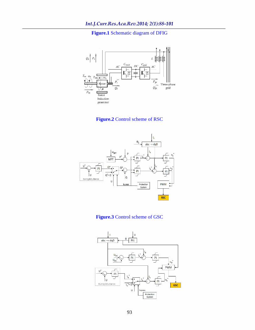
Figure 1 shows the schematic diagram of DFIG used in windfarm (Poller, 2003). This concept uses a wound rotor induction generator whose stator windings are
directly connected to the grid, while the rotor winding is connected to the network via a back-to-back IGBT-based converter. The Rotor Side Converter (RSC) regulates the active and reactive power injected by the DFIG and the Grid Side Converter (GSC) controls the voltage at the DC link. When the machine produces energy, only a small part of the generated power flows from the rotor to the grid. The converters can then be chosen in accordance with this small rotor power. Generally the absolute value of slip is much lower than 1 and consequently the rotor electrical power output Pr is only a fraction of stator real power output Ps. The electromagnetic torque Tm is positive for power generation and s is positive and constant for a constant frequency grid voltage. So, the sign of Pr is a function of the slip sign.
Pr is positive for negative slip (speed greater than synchronous speed) and it is negative for positive slip (speed lower than synchronous speed). For super synchronous speed operation, Pr is transmitted to DC bus capacitor and tends to raise the DC voltage. For sub synchronous speed operation, Pr is taken out of the DC bus capacitor and tends to decrease the DC bus voltage. The GSC is used to generate or absorb the grid electrical power Pgc in order to keep the DC voltage constant. In steady state, for a lossless AC/DC/AC converter, Pgc is equal to Pr and the speed of the wind turbine is determined by the power Pr absorbed or generated by RSC.
Modeling of WEG in DigSILENT power factory
The overall structure of WEG model comprises of the aerodynamic model of wind speed, mechanical model of drive train and electrical model of generator (Camille Hamon, 2010). The well known
90
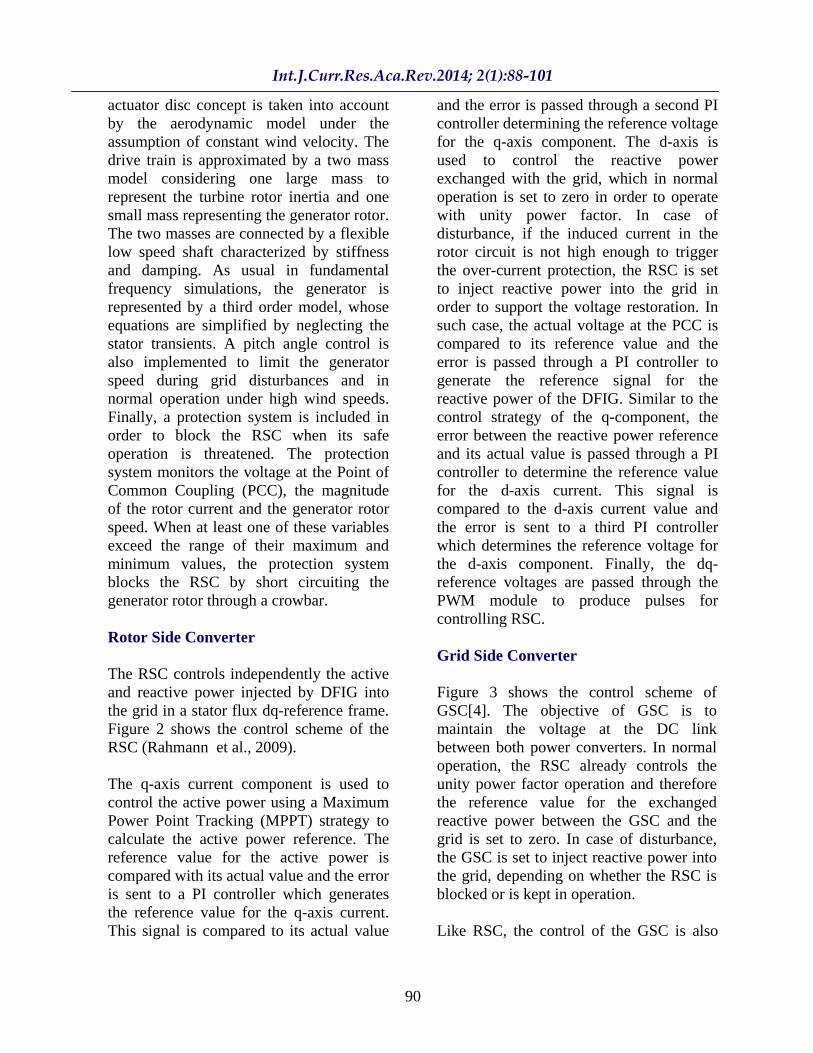
actuator disc concept is taken into account by the aerodynamic model under the assumption of constant wind velocity. The drive train is approximated by a two mass model considering one large mass to represent the turbine rotor inertia and one small mass representing the generator rotor. The two masses are connected by a flexible low speed shaft characterized by stiffness and damping. As usual in fundamental frequency simulations, the generator is represented by a third order model, whose equations are simplified by neglecting the stator transients. A pitch angle control is also implemented to limit the generator speed during grid disturbances and in normal operation under high wind speeds. Finally, a protection system is included in order to block the RSC when its safe operation is threatened. The protection system monitors the voltage at the Point of Common Coupling (PCC), the magnitude of the rotor current and the generator rotor speed. When at least one of these variables exceed the range of their maximum and minimum values, the protection system blocks the RSC by short circuiting the generator rotor through a crowbar.
Rotor Side Converter
The RSC controls independently the active and reactive power injected by DFIG into the grid in a stator flux dq-reference frame. Figure 2 shows the control scheme of the RSC (Rahmann et al., 2009).
The q-axis current component is used to control the active power using a Maximum Power Point Tracking (MPPT) strategy to calculate the active power reference. The reference value for the active power is compared with its actual value and the error is sent to a PI controller which generates the reference value for the q-axis current. This signal is compared to its actual value
and the error is passed through a second PI controller determining the reference voltage for the q-axis component. The d-axis is used to control the reactive power exchanged with the grid, which in normal operation is set to zero in order to operate with unity power factor. In case of disturbance, if the induced current in the rotor circuit is not high enough to trigger the over-current protection, the RSC is set to inject reactive power into the grid in order to support the voltage restoration. In such case, the actual voltage at the PCC is compared to its reference value and the error is passed through a PI controller to generate the reference signal for the reactive power of the DFIG. Similar to the control strategy of the q-component, the error between the reactive power reference and its actual value is passed through a PI controller to determine the reference value for the d-axis current. This signal is compared to the d-axis current value and the error is sent to a third PI controller which determines the reference voltage for the d-axis component. Finally, the dq-reference voltages are passed through the PWM module to produce pulses for controlling RSC.
Grid Side Converter
Figure 3 shows the control scheme of GSC[4]. The objective of GSC is to maintain the voltage at the DC link between both power converters. In normal operation, the RSC already controls the unity power factor operation and therefore the reference value for the exchanged reactive power between the GSC and the grid is set to zero. In case of disturbance, the GSC is set to inject reactive power into the grid, depending on whether the RSC is blocked or is kept in operation.
Like RSC, the control of the GSC is also

91
performed using the dq- reference frame, but instead of rotating with the stator flux, the axis rotates with the grid voltage. The actual voltage at the DC link is compared with its reference value and the error between both signals is passed through a PI controller which determines the reference signal for the d-axis current. This latter signal is subtracted with its current value and the error is sent to another PI controller to obtain the reference voltage for the d-axis component. As for the q-axis current, its reference value depends whether the system operates in normal operation or during disturbance. In normal operation, the GSC is assumed reactive neutral by setting the reference value of the q-axis current to zero. In case of disturbance, the actual AC-side voltage of the GSC is compared with its reference value and the error is passed through a PI controller which generates the reference signal for the q-axis current. This reference signal is compared to its current value and the error is sent to a second PI controller which establishes the reference voltage for the q-axis component. Finally, both reference voltages in a dq-reference frame are sent to the PWM module which generates pulses for control of GSC.
FRT capability of DFIG based WEG
FRT capability of WEG is defined as the capability of the generator to remain connected to the grid under grid disturbances. Below are a few scenarios describing what should happen to DFIG during and after a voltage drop resulting from a load disturbance or other fault (Joshua Earnest and Tore Wizelius, 2011).
(i)DFIG should be disconnected from the AC grid temporarily until the dip disappears, after which the machine should be reconnected. (ii)DFIG should never be disconnected
from the grid and should remain constantly operational.
(iii)DFIG should stay connected and act as a reactive power source to support the grid voltage.
Around the world, network operators issue grid codes, which determine which operational behavior should occur or what action should be taken when any fault has occurred. For example according to the German grid code, WEG during a fault period (e.g., a short-circuit fault) must provide voltage support or reactive power support by increasing the provided reactive current to the grid. Two most effective factors determining the FRT capability of DFIG based wind turbines are converter control and converter protection system. These Two factors influence the performance of DFIG during normal operation as well. During fault incidence, the voltage at the DFIG terminal dips down, causing a high transient rotor current. To protect the rotor winding of DFIG and its converter circuits, a rotor over current protection called crowbar is applied. The crowbar provides a safe route for the high transient rotor current by short circuiting the generator rotor windings, switching the Crowbar to protect the RSC during faults. Several principles and guidelines should be considered in designing crowbar protection. Crowbar technique is a useful way to solve FRT capability of WEG. When a crowbar protection was applied, it was noted that FRT capability can be improved by using a proper value of crowbar resistance. Furthermore, to damp the torsion oscillation in the drive train caused by grid sag, a damping controller was applied to a thyristor crowbar [5]. A disadvantage of the crowbar protection method is during a fault, the controllability of a DFIG is lost as

92
it will behave as a conventional Squirrel Cage Induction Generator (SCIG).
Simulation of transient stability analysis in DigSILENT power factory
Transient stability analysis is used for dynamic analysis over time periods from few seconds to few minutes depending on the time constants of the dynamic phenomenon modeled. Transient Stability Analysis is the simulation module dedicated to simulate electromechanical transients in three phase electric power systems. Thus for the considered network, transient stability analysis is done in order to determine the dynamic behavior of the DFIG with and without crowbar resistance during weak disturbances and also the strong disturbances.
The various steps needed to do the simulation of DFIG based WEG in DigSILENT are as follows (http://www.digsilent.de/):
(i)A single line diagram of DFIG based wind farm is created using built in models in DigSILENT power factory.
(ii)The transient stability of WEG is analyzed by creating short circuit events and the dynamic behavior of DFIG is obtained.
(iii)The dynamic behavior of DFIG with and without crow bar protection is studied and the results are compared.
Figure 4 shows the electrical network which is used for simulating the transient stability analysis of the particular DFIG wind farm. The network consists of 60 MW capacity DFIG based wind farm and two synchronous generators each of 40MW capacity connected to the grid.
Simulation study of DFIG during strong disturbance
Case study-1: 3 phase fault at HV (110 kV) bus near to wind farm. (Without crowbar)
The 3 phase short circuit was created at HV bus near to the wind farm and the transient behavior of DFIG is studied. The results obtained are shown in the form of graphs in Figure 5.
When the fault was created at the HV bus at 0 second there is a voltage dip to 0.40p.u at HV bus and 0.49p.u at MV bus. The rotor speed is increased from 1.2p.u. to about 1.25p.u.
With respect to the change in speed, there is a variation in pitch angle between 0 degree to 2 degree. The currents in the rotor is suddenly raised to about 2.1 times the rated capacity of the rotor. The fault is cleared at 150ms. At this moment, the voltage is rising to its pre fault level. The speed and also pitch angle is also reducing after the clearance of fault. The value of rotor current is also reduced after the fault. In post fault condition the rotor current reached the value of about 0.8p.u.
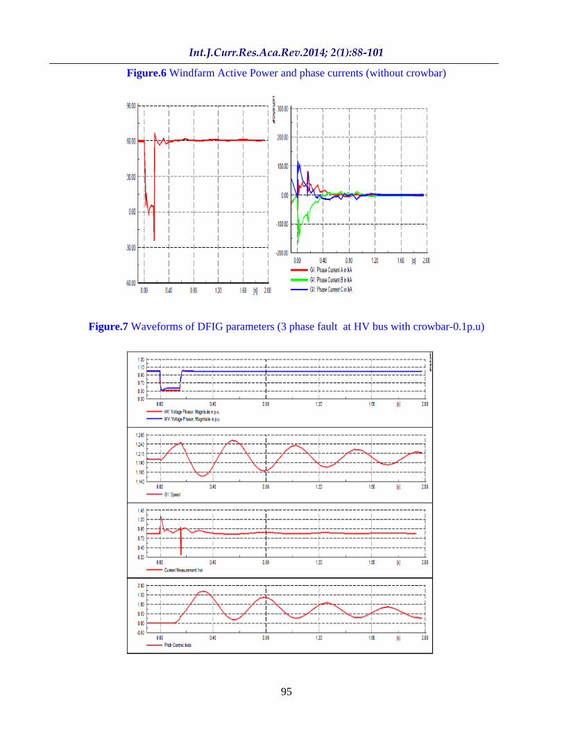
As shown in Figure 6, the active power generated by DFIG wind farm before fault is about 60MW. When the fault occurred, there is a reduction of power to 10MW till 10ms there after it reached to zero value at 100ms then there is a slight increase in power. After the fault clearance, it regained to its original value. The phase currents of generator are also raised to about 100 kA when the fault was occurred; it came to original value after the clearance of the fault. This is the behavior of DFIG wind farm during the strong disturbance occurred nearer to the wind farm at HV bus without crowbar protection.
93
Figure.1 Schematic diagram of DFIG
Figure.2 Control scheme of RSC
Figure.3 Control scheme of GSC

94
Figure.4 Wind farm network
Figure.5 Waveforms of DFIG parameters (3-p fault at HV bus without crow bar)
95
Figure.6 Windfarm Active Power and phase currents (without crowbar)
Figure.7 Waveforms of DFIG parameters (3 phase fault at HV bus with crowbar-0.1p.u)

96
Case Study-2: 3-phase fault at HV (110 kV) bus near to wind farm. (With crowbar-0.1p.u)
From this study the, dynamical behavior of DFIG with crowbar can be obtained. The results are shown in Figure 7 and Figure 8. From the results, it is seen that the voltage profile was increased to 0.5p.u and 0.6p.u of HV and MV bus of wind farm when crowbar is connected to DFIG. So there is a voltage support to the grid during faults. During the fault instant the speed is increased from 1.2p.u to about 1.24p.u. With respect to the change in speed there is a variation in pitch angle between 0 degree to 1.5 degree and after some time, it has become stable. When crowbar of value 0.1p.u is inserted, the speed is reduced when compared with when crowbar is not connected. The currents in the rotor is suddenly raised when the fault has occurred to a value of about 2.1p.u, which represents that the value of current is about 2.1 times the rated capacity of the rotor. Interestingly when the crowbar is inserted at a time of 0.01sec, the currents in the rotor are reduced. The value of current during crowbar activation is about 0.9p.u.This ensures the safe operation of rotor. So, the machine can run as an ordinary induction machine when the crowbar is activated. So instead of getting the machine to trip, it can run and it can ride through the fault.
From the results, it can be stated that there is support of reactive power from the DFIG in order to support voltage stability, when the crowbar is activated. But when the crowbar is deactivated at 150.11ms, the DFIG draws huge reactive power till the rotor converter comes backs to operation. The active power by the farm is in supportive to the grid instead of reaching to zero. During fault period also, it is capable of supplying power to the grid when
crowbar is connected, the magnitudes of phase currents are also reduced to safe values very quickly during the fault. After the fault, it came to its stable state.
Case study-3: 3-phase fault at HV (110 kV) bus near to wind farm. (With crowbar-0.25p.u)
From this study the dynamical behavior of DFIG with crowbar of value 0.25p.u can be obtained. The results are shown in Figure 9 and Figure 10. During the fault instant the speed is increased from 1.2p.u to about 1.24p.u as same as that of when crowbar with 0.1 value is connected. With respect to the change in speed there is a variation in pitch angle between 0 degree to 1.5 degree and after some time. it s becoming stable. The currents in the rotor is suddenly raised to a value of about 2.1p.u. When the crowbar of value 0.25p.u is inserted at a time of 0.01sec,the currents in the rotor are reduced.The value of current during crowbar of 0.25p.u activation is about 0.75p.u.approximately, but when the crowbar of value 0.25p.u is removed, at that instant there is huge rise of currents to about 1.3p.u until the rotor circuit is connected to the converter.
This ensures the safe operation of rotor if the RSC is connected as soon as possible after the removal of crowbar.It can be summarized that when the crowbar is connected to the rotor circuit, DFIG can have the capability of riding the fault. But choosing the right value of crowbar ensures better operation during the fault period. From the above results of different crowbar values 0.1p.u and 0.25p.u, it seems that the crowbar with value of 0.1p.u seems to be optimal because at the time of disconnection there is no high rise of currents just when compared with other crowbar of 0.25p.u value.
97
Thus when the crowbar of optimal value is connected in the rotor circuit during fault, the DFIG can obtain the FRT capability. Table 1 shows the average voltage levels (p.u) for different faults with different CrowBar (CB) values at MV and HV Bus under Strong disturbance
Simulation study of DFIG during weak disturbance
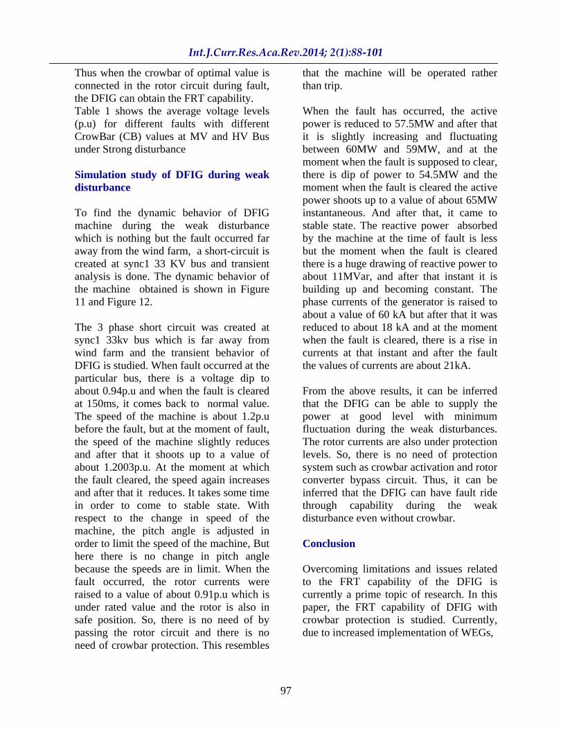
To find the dynamic behavior of DFIG machine during the weak disturbance which is nothing but the fault occurred far away from the wind farm, a short-circuit is created at sync1 33 KV bus and transient analysis is done. The dynamic behavior of the machine obtained is shown in Figure 11 and Figure 12.
The 3 phase short circuit was created at sync1 33kv bus which is far away from wind farm and the transient behavior of DFIG is studied. When fault occurred at the particular bus, there is a voltage dip to about 0.94p.u and when the fault is cleared at 150ms, it comes back to normal value. The speed of the machine is about 1.2p.u before the fault, but at the moment of fault, the speed of the machine slightly reduces and after that it shoots up to a value of about 1.2003p.u. At the moment at which the fault cleared, the speed again increases and after that it reduces. It takes some time in order to come to stable state. With respect to the change in speed of the machine, the pitch angle is adjusted in order to limit the speed of the machine, But here there is no change in pitch angle because the speeds are in limit. When the fault occurred, the rotor currents were raised to a value of about 0.91p.u which is under rated value and the rotor is also in safe position. So, there is no need of by passing the rotor circuit and there is no need of crowbar protection. This resembles
that the machine will be operated rather than trip.
When the fault has occurred, the active power is reduced to 57.5MW and after that it is slightly increasing and fluctuating between 60MW and 59MW, and at the moment when the fault is supposed to clear, there is dip of power to 54.5MW and the moment when the fault is cleared the active power shoots up to a value of about 65MW instantaneous. And after that, it came to stable state. The reactive power absorbed by the machine at the time of fault is less but the moment when the fault is cleared there is a huge drawing of reactive power to about 11MVar, and after that instant it is building up and becoming constant. The phase currents of the generator is raised to about a value of 60 kA but after that it was reduced to about 18 kA and at the moment when the fault is cleared, there is a rise in currents at that instant and after the fault the values of currents are about 21kA.
From the above results, it can be inferred that the DFIG can be able to supply the power at good level with minimum fluctuation during the weak disturbances. The rotor currents are also under protection levels. So, there is no need of protection system such as crowbar activation and rotor converter bypass circuit. Thus, it can be inferred that the DFIG can have fault ride through capability during the weak disturbance even without crowbar.
Conclusion
Overcoming limitations and issues related to the FRT capability of the DFIG is currently a prime topic of research. In this paper, the FRT capability of DFIG with crowbar protection is studied. Currently, due to increased implementation of WEGs,

98
Figure.8 Waveforms at wind farm connection points (with crowbar=0.1 p.u)
Figure.9 Wave forms of DFIG parameters (3-p fault at HV bus with crowbar-0.25p.u)

99
Figure.10 Waveforms at Wind farm connection points (with crowbar -0.25p.u)
Table.1 Voltage levels (p.u) for different faults with different crowbar value at MV and HV Bus (Strong disturbance)

100
Figure.11 Wave forms of DFIG parameters (3-p fault at sync1 33kv bus)
Figure.12 Waveforms at Wind farm connection points (3phase fault at sync1 33kv bus)

101
most system operators demand that a WEG should support the voltage recovery after the grid faults. Consequently, the RSC controller is modified to support the grid voltage and improve FRT capability during a fault. The capability of the crowbar circuit in rotor to improve voltage support during a fault has been affirmed. For different faults with different crowbar values for strong and weak disturbances, the simulation of DFIG is done using DigSILENT software. From the results, it is concluded that by properly choosing the value of crowbar resistance, better FRT capabilities of DFIG can be achieved.
References
Camille Hamon,.2010. Doubly-fed Induction Generator Modeling and Control in DigSilent Power Factory , Masters Thesis,RTH.
http://www.digsilent.de/ Joshua Earnest and Tore Wizelius, 2011.
Wind Power Plants and Project Development , PHI.
Poller, M.A., 2003. Doubly-Fed Induction Machine Models for Stability Assessment of Wind Farms , IEEE Power Tech Conference Proceedings, Vol.3, June 23-26.
Rahmann, C., H..J. Haubrich, L. Vargas and M. B. C. Salles 2009. Investigation of DFIG with Fault
Ride-Through Capability in Weak Power Systems , International Conference on Power Systems Transients, June 3-6.
Vladislav Akhmatov, 2005. Induction Generators for Wind Power , Multi-Science Publishing Company.