iso15144-2: examples 1 to 4, using method a and b · iso15144-2: examples 1 to 4, using method a...
TRANSCRIPT

1 / 35 KISSsoft AG Rosengartenstr. 4 8608 Bubikon Switzerland T. +41 55 254 20 50 [email protected] www.KISSsoft.AG
ISO15144-2: Examples 1 to 4, using Method A and B
Reviewed by U. Kissling, 10 nov 2014 Note: In the examples of ISO15144-2 the tip relief factor XCa is calculated following method B. In KISSsoft we use Method A (which is more precise). In order to get the same results as in 15144-2, we just set the tip relief Ca to 0.
Calculation of examples 1 to 4 with Method A and B, comparing our results with results presented in draft ISO TR 15144-2(2014)
Example 1 : mn=10.93, =0, z=18/18 Example 2 : mn=10, =0, z=20/20 Example 3 : mn=4.5, =19.578, z=33/34 Example 4 : mn=8, =14.5, z=21/67 Resume:
What Result in 15144-2
Our result Comment
Example 1, Method B S=0.644 0.644 OK
Example 2, Method B (no tip relief considered)
S=0.353 0.353 OK
Example 3, Method A 1.124 1.208 We considered all contact points (not only A, AB, etc.). See note.
Example 3, Method B (no tip relief considered)
S=0.884 0.8848 OK
Example 3, Method B (tip relief considered)
1.148 For information only
Example 4, Method A 1.158 1.282 OK
Example 4, Method B (no tip relief considered)
S= 0.894 0.8948 OK. See note.
Note: Examples using Method A (Hertzian pressure from LCA): Pressure distribution is slightly different in KISSsoft Contact analysis than the data given as input in the examples. Furthermore any flank line modification (or shaft bending data) is not indicated, therefore the load distribution over the face width can not be reproduced.

2 / 35 KISSsoft AG Rosengartenstr. 4 8608 Bubikon Switzerland T. +41 55 254 20 50 [email protected] www.KISSsoft.AG
Example 3, Method A
Example 4, Method A

3 / 35 KISSsoft AG Rosengartenstr. 4 8608 Bubikon Switzerland T. +41 55 254 20 50 [email protected] www.KISSsoft.AG
Data Overview
Example 1, Method B
4b. MICROPITTING ACCORDING TO ISO TR 15144-1:2010
Calculation of permissible specific film thickness
Lubricant load according to FVA Info sheet 54/7 8 (Oil:)
Reference data FZG-C Test:
Torque (Nm) [T1Ref] 171.6
Line load at contact point A (N/mm) [FbbRef,A] 153.7
Oil temperature (°C) [theOilRef] 90.0
Tooth mass temperature (°C) [theMRef] 115.9
Contact temperature (°C) [theBRef,A] 198.4
Lubrication gap thickness (µm) [hRef,A] 0.075
Specific film thickness in test (µm) [lamGFT] 0.151
Material coefficient [WW] 1.00
Permissible specific film thickness (µm) [lamGFP] 0.211
Intermediate results according to ISO TR 15144:2010
Coefficient of friction [mym] 0.048
Lubricant factor [XL] 1.000
Roughness factor [XR] 1.025
Tooth mass temperature (°C) [theM] 153.6
Tip relief factor [XCa (A)] 1.000
Loss factor [HV] 0.204
Equivalent Young's modulus (N/mm²) [Er] 226374
Compressed viscosity index (m2/N) [alf38] 0.02150
Dynamic viscosity (Ns/m2) [etatM] 4.7
Roughness average value (µm) [Ra] 0.9
Calculation of speeds, load distribution and flank curvature according to method B following ISO 15144-1:2010
With modifications following ISO TR CD 15144-2:2013
Ca taken as optimal in the calculation (0=no, 1=yes) 0 0
Minimal specific film thickness (µm) [lamGFY] 0.136 (hY=0.122 µm)
Safety against micropitting [Slam] 0.644
Calculation Micropitting ISO TR 15144, Methode B Pair 1-2 gA = 0.000 gAB = 6.626 gB = 13.253 gC = 22.760 gD = 32.267 gDE = 38.893 gE = 45.519 Er = 226373.6 Ra = 0.900 ZE = 189.812 XL = 1.000 XS = 1.200 XCa = 1.000 mym = 0.048 theM = 153.604 etaTm= 4.652 alf38= 0.0215 *1e-6 alfTm= 0.0118 *1e-6 A: dA,1 = 187.419 dA,2 = 221.400 rt1,A = 15.389 rt2,A = 60.908 ron,A = 12.285 XbutA = 1.000 XA = 0.333 PH,A,B = 963.371 Pdin,A,B = 1083.525 Vr1,A = 4.835 Vr2,A = 19.135

4 / 35 KISSsoft AG Rosengartenstr. 4 8608 Bubikon Switzerland T. +41 55 254 20 50 [email protected] www.KISSsoft.AG
Vg,A = -14.300 VSig,A = 23.969 ThetaFl,A= 175.285 TheB,A = 328.889 (GM,A = 2678.6 U,A = 20.047*10^-12 W,A = 1.439*10^-4 SGF,A = 0.057) h,A = 0.1224 lamGF,A = 0.136 Slam,A = 0.644 AB: dAB,1 = 190.046 dAB,2 = 214.394 rt1,AB = 22.015 rt2,AB = 54.282 ron,AB = 15.663 XbutAB = 1.000 XAB = 0.500 PH,AB,B = 1044.941 Pdin,AB,B = 1175.268 Vr1,AB = 6.916 Vr2,AB = 17.053 Vg,AB = -10.137 VSig,AB = 23.969 ThetaFl,AB= 154.120 TheB,AB = 307.724 (GM,AB = 2678.6 U,AB = 15.723*10^-12 W,AB = 1.694*10^-4 SGF,AB = 0.076) h,AB = 0.1374 lamGF,AB = 0.153 Slam,AB = 0.723 B: dB,1 = 193.546 dB,2 = 207.998 rt1,B = 28.641 rt2,B = 47.655 ron,B = 17.890 XbutB = 1.000 XB = 1.000 PH,B,B = 1382.739 Pdin,B,B = 1555.197 Vr1,B = 8.998 Vr2,B = 14.971 Vg,B = -5.974 VSig,B = 23.969 ThetaFl,B= 145.392 TheB,B = 298.996 (GM,B = 2678.6 U,B = 13.766*10^-12 W,B = 2.966*10^-4 SGF,B = 0.086) h,B = 0.1365 lamGF,B = 0.152 Slam,B = 0.718 C: dC,1 = 200.000 dC,2 = 200.000 rt1,C = 38.148 rt2,C = 38.148 ron,C = 19.074 XbutC = 1.000 XC = 1.000 PH,C,B = 1339.111 Pdin,C,B = 1506.128 Vr1,C = 11.985 Vr2,C = 11.985 Vg,C = 0.000 VSig,C = 23.969 ThetaFl,C= 0.000 TheB,C = 153.604 (GM,C = 2678.6 U,C = 12.911*10^-12 W,C = 2.781*10^-4 SGF,C = 1.000) h,C = 0.2406 lamGF,C = 0.267 Slam,C = 1.266 D: dD,1 = 207.998 dD,2 = 193.546 rt1,D = 47.655 rt2,D = 28.641 ron,D = 17.890 XbutD = 1.000 XD = 1.000 PH,D,B = 1382.739 Pdin,D,B = 1555.197 Vr1,D = 14.971 Vr2,D = 8.998 Vg,D = 5.974 VSig,D = 23.969 ThetaFl,D= 145.393 TheB,D = 298.996 (GM,D = 2678.6 U,D = 13.766*10^-12 W,D = 2.966*10^-4 SGF,D = 0.086) h,D = 0.1365 lamGF,D = 0.152 Slam,D = 0.718 DE: dDE,1 = 214.394 dDE,2 = 190.046 rt1,DE = 54.282 rt2,DE = 22.015 ron,DE = 15.663 XbutDE = 1.000 XDE = 0.500 PH,DE,B = 1044.941 Pdin,DE,B = 1175.268 Vr1,DE = 17.053 Vr2,DE = 6.916 Vg,DE = 10.137 VSig,DE = 23.969

5 / 35 KISSsoft AG Rosengartenstr. 4 8608 Bubikon Switzerland T. +41 55 254 20 50 [email protected] www.KISSsoft.AG
ThetaFl,DE= 154.120 TheB,DE = 307.724 (GM,DE = 2678.6 U,DE = 15.723*10^-12 W,DE = 1.694*10^-4 SGF,DE = 0.076) h,DE = 0.1374 lamGF,DE = 0.153 Slam,DE = 0.723 E: dE,1 = 221.400 dE,2 = 187.419 rt1,E = 60.908 rt2,E = 15.389 ron,E = 12.285 XbutE = 1.000 XE = 0.333 PH,E,B = 963.371 Pdin,E,B = 1083.525 Vr1,E = 19.135 Vr2,E = 4.835 Vg,E = 14.300 VSig,E = 23.969 ThetaFl,E= 175.285 TheB,E = 328.889 (GM,E = 2678.6 U,E = 20.047*10^-12 W,E = 1.439*10^-4 SGF,E = 0.057) h,E = 0.1224 lamGF,E = 0.136 Slam,E = 0.644
Example 2, Method B without considering tip relief Ca
4b. MICROPITTING ACCORDING TO ISO TR 15144-1:2010
Calculation of permissible specific film thickness
Lubricant load according to FVA Info sheet 54/7 10 (Oil:)
Reference data FZG-C Test:
Torque (Nm) [T1Ref] 265.1
Line load at contact point A (N/mm) [FbbRef,A] 236.3
Oil temperature (°C) [theOilRef] 70.0
Tooth mass temperature (°C) [theMRef] 107.1
Contact temperature (°C) [theBRef,A] 228.6
Lubrication gap thickness (µm) [hRef,A] 0.061
Specific film thickness in test (µm) [lamGFT] 0.122
Material coefficient [WW] 1.00
Permissible specific film thickness (µm) [lamGFP] 0.171
Intermediate results according to ISO TR 15144:2010
Coefficient of friction [mym] 0.067
Lubricant factor [XL] 1.000
Roughness factor [XR] 1.023
Tooth mass temperature (°C) [theM] 126.6
Tip relief factor [XCa (A)] 1.000
Loss factor [HV] 0.206
Equivalent Young's modulus (N/mm²) [Er] 226374
Compressed viscosity index (m2/N) [alf38] 0.02052
Dynamic viscosity (Ns/m2) [etatM] 6.4
Roughness average value (µm) [Ra] 0.8
Calculation of speeds, load distribution and flank curvature according to method B following ISO 15144-1:2010
With modifications following ISO TR CD 15144-2:2013
Ca taken as optimal in the calculation (0=no, 1=yes) 0 0
Minimal specific film thickness (µm) [lamGFY] 0.060 (hY=0.048 µm)
Safety against micropitting [Slam] 0.353
Calculation Micropitting ISO TR 15144, Methode B Pair 1-2 gA = 0.000 gAB = 8.219 gB = 16.439 gC = 22.980 gD = 29.521 gDE = 37.741

6 / 35 KISSsoft AG Rosengartenstr. 4 8608 Bubikon Switzerland T. +41 55 254 20 50 [email protected] www.KISSsoft.AG
gE = 45.960 Er = 226373.6 Ra = 0.800 ZE = 189.812 XL = 1.000 XS = 1.200 XCa = 1.000 mym = 0.067 theM = 126.576 etaTm= 6.443 alf38= 0.0205 *1e-6 alfTm= 0.0130 *1e-6 A: dA,1 = 189.274 dA,2 = 220.000 rt1,A = 11.222 rt2,A = 57.182 ron,A = 9.381 XbutA = 1.000 XA = 0.333 PH,A,B = 1476.400 Pdin,A,B = 1541.337 Vr1,A = 1.175 Vr2,A = 5.988 Vg,A = -4.813 VSig,A = 7.163 ThetaFl,A= 225.690 TheB,A = 352.266 (GM,A = 2936.2 U,A = 10.867*10^-12 W,A = 2.913*10^-4 SGF,A = 0.024) h,A = 0.0483 lamGF,A = 0.060 Slam,A = 0.353 AB: dAB,1 = 191.919 dAB,2 = 211.920 rt1,AB = 19.441 rt2,AB = 48.963 ron,AB = 13.916 XbutAB = 1.000 XAB = 0.500 PH,AB,B = 1484.636 Pdin,AB,B = 1549.934 Vr1,AB = 2.036 Vr2,AB = 5.127 Vg,AB = -3.091 VSig,AB = 7.163 ThetaFl,AB= 170.319 TheB,AB = 296.895 (GM,AB = 2936.2 U,AB = 7.325*10^-12 W,AB = 2.945*10^-4 SGF,AB = 0.049) h,AB = 0.0639 lamGF,AB = 0.080 Slam,AB = 0.468 B: dB,1 = 195.912 dB,2 = 204.844 rt1,B = 27.661 rt2,B = 40.743 ron,B = 16.475 XbutB = 1.000 XB = 1.000 PH,B,B = 1929.617 Pdin,B,B = 2014.487 Vr1,B = 2.897 Vr2,B = 4.267 Vg,B = -1.370 VSig,B = 7.163 ThetaFl,B= 119.228 TheB,B = 245.804 (GM,B = 2936.2 U,B = 6.187*10^-12 W,B = 4.976*10^-4 SGF,B = 0.102) h,B = 0.0736 lamGF,B = 0.092 Slam,B = 0.539 C: dC,1 = 200.000 dC,2 = 200.000 rt1,C = 34.202 rt2,C = 34.202 ron,C = 17.101 XbutC = 1.000 XC = 1.000 PH,C,B = 1893.996 Pdin,C,B = 1977.300 Vr1,C = 3.582 Vr2,C = 3.582 Vg,C = 0.000 VSig,C = 7.163 ThetaFl,C= 0.000 TheB,C = 126.576 (GM,C = 2936.2 U,C = 5.961*10^-12 W,C = 4.794*10^-4 SGF,C = 1.000) h,C = 0.1236 lamGF,C = 0.155 Slam,C = 0.905 D: dD,1 = 204.844 dD,2 = 195.912 rt1,D = 40.743 rt2,D = 27.661 ron,D = 16.475 XbutD = 1.000

7 / 35 KISSsoft AG Rosengartenstr. 4 8608 Bubikon Switzerland T. +41 55 254 20 50 [email protected] www.KISSsoft.AG
XD = 1.000 PH,D,B = 1929.617 Pdin,D,B = 2014.487 Vr1,D = 4.267 Vr2,D = 2.897 Vg,D = 1.370 VSig,D = 7.163 ThetaFl,D= 119.228 TheB,D = 245.804 (GM,D = 2936.2 U,D = 6.187*10^-12 W,D = 4.976*10^-4 SGF,D = 0.102) h,D = 0.0736 lamGF,D = 0.092 Slam,D = 0.539 DE: dDE,1 = 211.920 dDE,2 = 191.919 rt1,DE = 48.963 rt2,DE = 19.441 ron,DE = 13.916 XbutDE = 1.000 XDE = 0.500 PH,DE,B = 1484.636 Pdin,DE,B = 1549.934 Vr1,DE = 5.127 Vr2,DE = 2.036 Vg,DE = 3.091 VSig,DE = 7.163 ThetaFl,DE= 170.319 TheB,DE = 296.895 (GM,DE = 2936.2 U,DE = 7.325*10^-12 W,DE = 2.945*10^-4 SGF,DE = 0.049) h,DE = 0.0639 lamGF,DE = 0.080 Slam,DE = 0.468 E: dE,1 = 220.000 dE,2 = 189.274 rt1,E = 57.182 rt2,E = 11.222 ron,E = 9.381 XbutE = 1.000 XE = 0.333 PH,E,B = 1476.400 Pdin,E,B = 1541.337 Vr1,E = 5.988 Vr2,E = 1.175 Vg,E = 4.813 VSig,E = 7.163 ThetaFl,E= 225.690 TheB,E = 352.266 (GM,E = 2936.2 U,E = 10.867*10^-12 W,E = 2.913*10^-4 SGF,E = 0.024) h,E = 0.0483 lamGF,E = 0.060 Slam,E = 0.353
Example 3, Method A
4b. MICROPITTING ACCORDING TO ISO TR 15144-1:2010
Calculation of permissible specific film thickness
Lubricant load according to FVA Info sheet 54/7 8 (Öl:)
Reference data FZG-C Test:
Torque (Nm) [T1Ref] 171.6
Line load at contact point A (N/mm) [FbbRef,A] 153.7
Oil temperature (°C) [theOilRef] 90.0
Tooth mass temperature (°C) [theMRef] 116.7
Contact temperature (°C) [theBRef,A] 202.9
Lubrication gap thickness (µm) [hRef,A] 0.040
Specific film thickness in test (µm) [lamGFT] 0.080
Material coefficient [WW] 1.00
Permissible specific film thickness (µm) [lamGFP] 0.112
Intermediate results according to ISO TR 15144:2010
Coefficient of friction [mym] 0.054
Lubricant factor [XL] 1.000
Roughness factor [XR] 0.913
Tooth mass temperature (°C) [theM] 129.9
Tip relief factor [XCa (A)] 1.488
Loss factor [HV] 0.128

8 / 35 KISSsoft AG Rosengartenstr. 4 8608 Bubikon Switzerland T. +41 55 254 20 50 [email protected] www.KISSsoft.AG
Equivalent Young's modulus (N/mm²) [Er] 226374
Compressed viscosity index (m2/N) [alf38] 0.01875
Dynamic viscosity (Ns/m2) [etatM] 3.4
Roughness average value (µm) [Ra] 0.5
Calculation of speeds, load distribution and flank curvature according to ISO15144 method A with contact analysis
Minimal specific film thickness (µm) [lamGFY] 0.136 (hY=0.061 µm)
Safety against micropitting [Slam] 1.208
Safety S
Most critical point S = 1.208
Example 3, Method B, without considering tip relief Ca
4b. MICROPITTING ACCORDING TO ISO TR 15144-1:2010
Calculation of permissible specific film thickness
Lubricant load according to FVA Info sheet 54/7 8 (Öl:)
Reference data FZG-C Test:
Torque (Nm) [T1Ref] 171.6
Line load at contact point A (N/mm) [FbbRef,A] 153.7
Oil temperature (°C) [theOilRef] 90.0
Tooth mass temperature (°C) [theMRef] 116.7
Contact temperature (°C) [theBRef,A] 202.9
Lubrication gap thickness (µm) [hRef,A] 0.040
Specific film thickness in test (µm) [lamGFT] 0.080
Material coefficient [WW] 1.00
Permissible specific film thickness (µm) [lamGFP] 0.112

9 / 35 KISSsoft AG Rosengartenstr. 4 8608 Bubikon Switzerland T. +41 55 254 20 50 [email protected] www.KISSsoft.AG
Intermediate results according to ISO TR 15144:2010
Coefficient of friction [mym] 0.054
Lubricant factor [XL] 1.000
Roughness factor [XR] 0.913
Tooth mass temperature (°C) [theM] 149.3
Tip relief factor [XCa (A)] 1.000
Loss factor [HV] 0.128
Equivalent Young's modulus (N/mm²) [Er] 226374
Compressed viscosity index (m2/N) [alf38] 0.01875
Dynamic viscosity (Ns/m2) [etatM] 2.4
Roughness average value (µm) [Ra] 0.5
Calculation of speeds, load distribution and flank curvature according to method B following ISO 15144-1:2010
With modifications following ISO TR CD 15144-2:2013
Ca taken as optimal in the calculation (0=no, 1=yes) 0 0
Minimal specific film thickness (µm) [lamGFY] 0.099 (hY=0.045 µm)
Safety against micropitting [Slam] 0.8848
Calculation Micropitting ISO TR 15144, Methode B Pair 1-2 gA = 0.000 gAB = 3.813 gB = 7.626 gC = 10.832 gD = 13.997 gDE = 17.810 gE = 21.623 Er = 226373.6 Ra = 0.450 ZE = 189.812 XL = 1.000 XS = 1.200 XCa = 1.000 mym = 0.054 theM = 149.311 etaTm= 2.440 alf38= 0.0188 *1e-6 alfTm= 0.0106 *1e-6 A: dA,1 = 151.162 dA,2 = 171.390 rt1,A = 17.566 rt2,A = 40.090 ron,A = 12.869 XbutA = 1.300 XA = 0.841 PH,A,B = 1752.036 Pdin,A,B = 1882.929 Vr1,A = 5.518 Vr2,A = 12.224 Vg,A = -6.706 VSig,A = 17.743 ThetaFl,A= 241.698 TheB,A = 391.009 (GM,A = 2388.5 U,A = 7.431*10^-12 W,A = 4.347*10^-4 SGF,A = 0.030) h,A = 0.0447 lamGF,A = 0.099 Slam,A = 0.885 AB: dAB,1 = 153.115 dAB,2 = 167.957 rt1,AB = 21.379 rt2,AB = 36.277 ron,AB = 14.172 XbutAB = 1.000 XAB = 0.647 PH,AB,B = 1464.249 Pdin,AB,B = 1573.642 Vr1,AB = 6.716 Vr2,AB = 11.061 Vg,AB = -4.345 VSig,AB = 17.778 ThetaFl,AB= 124.041 TheB,AB = 273.352 (GM,AB = 2388.5 U,AB = 6.760*10^-12 W,AB = 3.036*10^-4 SGF,AB = 0.135) h,AB = 0.0675 lamGF,AB = 0.150 Slam,AB = 1.334 B: dB,1 = 155.417 dB,2 = 164.807 rt1,B = 25.192 rt2,B = 32.463 ron,B = 14.945 XbutB = 1.000 XB = 0.647

10 / 35 KISSsoft AG Rosengartenstr. 4 8608 Bubikon Switzerland T. +41 55 254 20 50 [email protected] www.KISSsoft.AG
PH,B,B = 1425.909 Pdin,B,B = 1532.437 Vr1,B = 7.914 Vr2,B = 9.899 Vg,B = -1.984 VSig,B = 17.813 ThetaFl,B= 55.508 TheB,B = 204.819 (GM,B = 2388.5 U,B = 6.424*10^-12 W,B = 2.879*10^-4 SGF,B = 0.361) h,B = 0.0859 lamGF,B = 0.191 Slam,B = 1.698 C: dC,1 = 157.612 dC,2 = 162.388 rt1,C = 28.398 rt2,C = 29.258 ron,C = 15.183 XbutC = 1.000 XC = 0.647 PH,C,B = 1414.682 Pdin,C,B = 1520.371 Vr1,C = 8.921 Vr2,C = 8.921 Vg,C = 0.000 VSig,C = 17.843 ThetaFl,C= 0.000 TheB,C = 149.311 (GM,C = 2388.5 U,C = 6.334*10^-12 W,C = 2.834*10^-4 SGF,C = 1.000) h,C = 0.1083 lamGF,C = 0.241 Slam,C = 2.142 D: dD,1 = 160.002 dD,2 = 160.216 rt1,D = 31.562 rt2,D = 26.093 ron,D = 15.050 XbutD = 1.000 XD = 0.647 PH,D,B = 1420.931 Pdin,D,B = 1527.088 Vr1,D = 9.916 Vr2,D = 7.956 Vg,D = 1.959 VSig,D = 17.872 ThetaFl,D= 54.618 TheB,D = 203.928 (GM,D = 2388.5 U,D = 6.400*10^-12 W,D = 2.859*10^-4 SGF,D = 0.366) h,D = 0.0866 lamGF,D = 0.192 Slam,D = 1.712 DE: dDE,1 = 163.161 dDE,2 = 157.897 rt1,DE = 35.376 rt2,DE = 22.280 ron,DE = 14.403 XbutDE = 1.000 XDE = 0.647 PH,DE,B = 1452.487 Pdin,DE,B = 1561.001 Vr1,DE = 11.114 Vr2,DE = 6.794 Vg,DE = 4.320 VSig,DE = 17.907 ThetaFl,DE= 122.360 TheB,DE = 271.670 (GM,DE = 2388.5 U,DE = 6.701*10^-12 W,DE = 2.988*10^-4 SGF,DE = 0.138) h,DE = 0.0686 lamGF,DE = 0.152 Slam,DE = 1.357 E: dE,1 = 166.610 dE,2 = 155.916 rt1,E = 39.189 rt2,E = 18.467 ron,E = 13.225 XbutE = 1.300 XE = 0.841 PH,E,B = 1728.290 Pdin,E,B = 1857.410 Vr1,E = 12.312 Vr2,E = 5.631 Vg,E = 6.681 VSig,E = 17.942 ThetaFl,E= 237.681 TheB,E = 386.992 (GM,E = 2388.5 U,E = 7.312*10^-12 W,E = 4.230*10^-4 SGF,E = 0.031) h,E = 0.0462 lamGF,E = 0.103 Slam,E = 0.913

11 / 35 KISSsoft AG Rosengartenstr. 4 8608 Bubikon Switzerland T. +41 55 254 20 50 [email protected] www.KISSsoft.AG
Example 3, Method B, considering tip relief Ca (for information only) Profile and tooth trace modifications for gear 1 Symmetric (both flanks) - Tip relief, linear Caa = 50.000µm LCa = 0.960*mn dCa = 162.726mm Profile and tooth trace modifications for gear 2 Symmetric (both flanks) - Tip relief, linear Caa = 50.000µm LCa = 0.960*mn dCa = 167.520mm
4b. MICROPITTING ACCORDING TO ISO TR 15144-1:2010
Calculation of permissible specific film thickness
Lubricant load according to FVA Info sheet 54/7 8 (Öl:)
Reference data FZG-C Test:
Torque (Nm) [T1Ref] 171.6
Line load at contact point A (N/mm) [FbbRef,A] 153.7
Oil temperature (°C) [theOilRef] 90.0
Tooth mass temperature (°C) [theMRef] 116.7
Contact temperature (°C) [theBRef,A] 202.9
Lubrication gap thickness (µm) [hRef,A] 0.040
Specific film thickness in test (µm) [lamGFT] 0.080
Material coefficient [WW] 1.00
Permissible specific film thickness (µm) [lamGFP] 0.112
Intermediate results according to ISO TR 15144:2010
Coefficient of friction [mym] 0.054
Lubricant factor [XL] 1.000
Roughness factor [XR] 0.913
Tooth mass temperature (°C) [theM] 129.9
Tip relief factor [XCa (A)] 1.488
Loss factor [HV] 0.128
Equivalent Young's modulus (N/mm²) [Er] 226374
Compressed viscosity index (m2/N) [alf38] 0.01875
Dynamic viscosity (Ns/m2) [etatM] 3.4
Roughness average value (µm) [Ra] 0.5
Calculation of speeds, load distribution and flank curvature according to method B following ISO 15144-1:2010
With modifications following ISO TR CD 15144-2:2013
Ca taken as optimal in the calculation (0=no, 1=yes) 0 0
Minimal specific film thickness (µm) [lamGFY] 0.129 (hY=0.058 µm)
Safety against micropitting [Slam] 1.148
Example 4, Method A
4b. MICROPITTING ACCORDING TO ISO TR 15144-1:2010
Calculation of permissible specific film thickness
Lubricant load according to FVA Info sheet 54/7 9 (Oil:)
Reference data FZG-C Test:
Torque (Nm) [T1Ref] 215.6
Line load at contact point A (N/mm) [FbbRef,A] 192.7
Oil temperature (°C) [theOilRef] 90.0
Tooth mass temperature (°C) [theMRef] 121.2
Contact temperature (°C) [theBRef,A] 221.9

12 / 35 KISSsoft AG Rosengartenstr. 4 8608 Bubikon Switzerland T. +41 55 254 20 50 [email protected] www.KISSsoft.AG
Lubrication gap thickness (µm) [hRef,A] 0.077
Specific film thickness in test (µm) [lamGFT] 0.153
Material coefficient [WW] 1.00
Permissible specific film thickness (µm) [lamGFP] 0.215
Intermediate results according to ISO TR 15144:2010
Coefficient of friction [mym] 0.060
Lubricant factor [XL] 1.000
Roughness factor [XR] 0.876
Tooth mass temperature (°C) [theM] 77.9
Tip relief factor [XCa (A)] 1.308
Loss factor [HV] 0.131
Equivalent Young's modulus (N/mm²) [Er] 230769
Compressed viscosity index (m2/N) [alf38] 0.02320
Dynamic viscosity (Ns/m2) [etatM] 43.9
Roughness average value (µm) [Ra] 0.7
Calculation of speeds, load distribution and flank curvature according to ISO15144 method A with contact analysis
Minimal specific film thickness (µm) [lamGFY] 0.261 (hY=0.175 µm)
Safety against micropitting [Slam] 1.282
Stress pdyn

13 / 35 KISSsoft AG Rosengartenstr. 4 8608 Bubikon Switzerland T. +41 55 254 20 50 [email protected] www.KISSsoft.AG
Specific film thickness Most critical point = 0.261
Safety S
Most critical point S = 1.282 (at right side of facewidth and root area of pinion)
Example 4, Method B, without considering tip relief Ca
4b. MICROPITTING ACCORDING TO ISO TR 15144-1:2010
Calculation of permissible specific film thickness
Lubricant load according to FVA Info sheet 54/7 9 (Oil:)
Reference data FZG-C Test:
Torque (Nm) [T1Ref] 215.6
Line load at contact point A (N/mm) [FbbRef,A] 192.7
Oil temperature (°C) [theOilRef] 90.0
Tooth mass temperature (°C) [theMRef] 121.2
Contact temperature (°C) [theBRef,A] 221.9
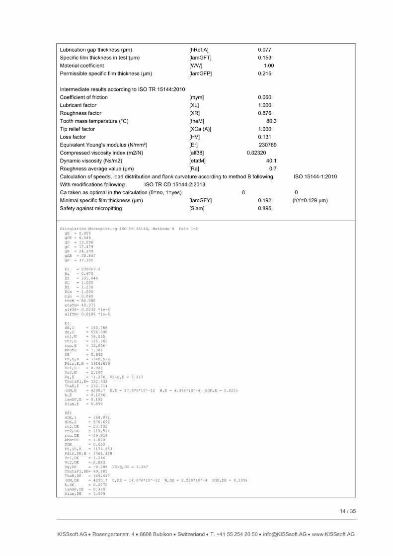
14 / 35 KISSsoft AG Rosengartenstr. 4 8608 Bubikon Switzerland T. +41 55 254 20 50 [email protected] www.KISSsoft.AG
Lubrication gap thickness (µm) [hRef,A] 0.077
Specific film thickness in test (µm) [lamGFT] 0.153
Material coefficient [WW] 1.00
Permissible specific film thickness (µm) [lamGFP] 0.215
Intermediate results according to ISO TR 15144:2010
Coefficient of friction [mym] 0.060
Lubricant factor [XL] 1.000
Roughness factor [XR] 0.876
Tooth mass temperature (°C) [theM] 80.3
Tip relief factor [XCa (A)] 1.000
Loss factor [HV] 0.131
Equivalent Young's modulus (N/mm²) [Er] 230769
Compressed viscosity index (m2/N) [alf38] 0.02320
Dynamic viscosity (Ns/m2) [etatM] 40.1
Roughness average value (µm) [Ra] 0.7
Calculation of speeds, load distribution and flank curvature according to method B following ISO 15144-1:2010
With modifications following ISO TR CD 15144-2:2013
Ca taken as optimal in the calculation (0=no, 1=yes) 0 0
Minimal specific film thickness (µm) [lamGFY] 0.192 (hY=0.129 µm)
Safety against micropitting [Slam] 0.895
Calculation Micropitting ISO TR 15144, Methode B Pair 1-2 gE = 0.000 gDE = 6.548 gD = 13.096 gC = 17.479 gB = 24.299 gAB = 30.847 gA = 37.395 Er = 230769.2 Ra = 0.670 ZE = 191.646 XL = 1.000 XS = 1.200 XCa = 1.000 mym = 0.060 theM = 80.282 etaTm= 40.071 alf38= 0.0232 *1e-6 alfTm= 0.0186 *1e-6 E: dE,1 = 165.768 dE,2 = 576.300 rt1,E = 16.555 rt2,E = 126.062 ron,E = 15.056 XbutE = 1.300 XE = 0.845 PH,E,B = 1540.522 Pdin,E,B = 1916.619 Vr1,E = 0.920 Vr2,E = 2.197 Vg,E = -1.276 VSig,E = 3.117 ThetaFl,E= 152.432 TheB,E = 232.714 (GM,E = 4290.7 U,E = 17.975*10^-12 W,E = 4.334*10^-4 SGF,E = 0.021) h,E = 0.1286 lamGF,E = 0.192 Slam,E = 0.895 DE: dDE,1 = 168.872 dDE,2 = 570.692 rt1,DE = 23.102 rt2,DE = 119.514 ron,DE = 19.919 XbutDE = 1.000 XDE = 0.650 PH,DE,B = 1174.653 Pdin,DE,B = 1461.428 Vr1,DE = 1.284 Vr2,DE = 2.083 Vg,DE = -0.798 VSig,DE = 3.367 ThetaFl,DE= 69.185 TheB,DE = 149.467 (GM,DE = 4290.7 U,DE = 14.676*10^-12 W,DE = 2.520*10^-4 SGF,DE = 0.109) h,DE = 0.2270 lamGF,DE = 0.339 Slam,DE = 1.579

15 / 35 KISSsoft AG Rosengartenstr. 4 8608 Bubikon Switzerland T. +41 55 254 20 50 [email protected] www.KISSsoft.AG
D: dD,1 = 172.914 dD,2 = 565.333 rt1,D = 29.650 rt2,D = 112.967 ron,D = 24.164 XbutD = 1.000 XD = 0.650 PH,D,B = 1066.497 Pdin,D,B = 1326.867 Vr1,D = 1.648 Vr2,D = 1.969 Vg,D = -0.320 VSig,D = 3.617 ThetaFl,D= 25.348 TheB,D = 105.629 (GM,D = 4290.7 U,D = 12.995*10^-12 W,D = 2.077*10^-4 SGF,D = 0.382) h,D = 0.3414 lamGF,D = 0.510 Slam,D = 2.375 C: dC,1 = 176.114 dC,2 = 561.886 rt1,C = 34.034 rt2,C = 108.583 ron,C = 26.660 XbutC = 1.000 XC = 0.650 PH,C,B = 1015.343 Pdin,C,B = 1263.226 Vr1,C = 1.892 Vr2,C = 1.892 Vg,C = 0.000 VSig,C = 3.784 ThetaFl,C= 0.000 TheB,C = 80.282 (GM,C = 4290.7 U,C = 12.324*10^-12 W,C = 1.883*10^-4 SGF,C = 1.000) h,C = 0.4543 lamGF,C = 0.678 Slam,C = 3.160 B: dB,1 = 181.821 dB,2 = 556.757 rt1,B = 40.854 rt2,B = 101.763 ron,B = 29.993 XbutB = 1.000 XB = 0.650 PH,B,B = 957.275 Pdin,B,B = 1190.981 Vr1,B = 2.271 Vr2,B = 1.773 Vg,B = 0.498 VSig,B = 4.045 ThetaFl,B= 35.368 TheB,B = 115.649 (GM,B = 4290.7 U,B = 11.708*10^-12 W,B = 1.674*10^-4 SGF,B = 0.276) h,B = 0.3773 lamGF,B = 0.563 Slam,B = 2.624 AB: dAB,1 = 188.071 dAB,2 = 552.104 rt1,AB = 47.402 rt2,AB = 95.215 ron,AB = 32.561 XbutAB = 1.000 XAB = 0.650 PH,AB,B = 918.752 Pdin,AB,B = 1143.053 Vr1,AB = 2.635 Vr2,AB = 1.659 Vg,AB = 0.976 VSig,AB = 4.294 ThetaFl,AB= 66.216 TheB,AB = 146.498 (GM,AB = 4290.7 U,AB = 11.451*10^-12 W,AB = 1.542*10^-4 SGF,AB = 0.118) h,AB = 0.3378 lamGF,AB = 0.504 Slam,AB = 2.350 A: dA,1 = 195.000 dA,2 = 547.725 rt1,A = 53.949 rt2,A = 88.667 ron,A = 34.510 XbutA = 1.300 XA = 0.845 PH,A,B = 1017.524 Pdin,A,B = 1265.938 Vr1,A = 2.999 Vr2,A = 1.545 Vg,A = 1.454 VSig,A = 4.544 ThetaFl,A= 115.846 TheB,A = 196.128 (GM,A = 4290.7 U,A = 11.433*10^-12 W,A = 1.891*10^-4 SGF,A = 0.041) h,A = 0.2755 lamGF,A = 0.411 Slam,A = 1.916

16 / 35 KISSsoft AG Rosengartenstr. 4 8608 Bubikon Switzerland T. +41 55 254 20 50 [email protected] www.KISSsoft.AG
Full geometry data
Example 1 KISSsoft Release 03/2014 E
KISSsoft-Entwicklungs-Version KISSsoft AG CH-8608 BUBIKON
File
Name : 15144-2_Expl1
Changed by: ukissling on: 11.11.2014 at: 11:34:04
CALCULATION OF A CYLINDRICAL SPUR GEAR PAIR
Drawing or article number:
Gear 1: 0.000.0
Gear 2: 0.000.0
Calculation method ISO 6336:2006 Method B
------- GEAR 1 -------- GEAR 2 --
Power (kW) [P] 589.991
Speed (1/min) [n] 3000.0 3000.0
Torque (Nm) [T] 1878.0 1878.0
Application factor [KA] 1.00
Required service life [H] 20000.00
Gear driving (+) / driven (-) + -
1. TOOTH GEOMETRY AND MATERIAL
(geometry calculation according to
DIN 3960:1987)
------- GEAR 1 -------- GEAR 2 –
Center distance (mm) [a] 200.000
Centre distance allowances (mm) [Aa.e/i] 0.050 / 0.050
Normal module (mm) [mn] 10.9300
Pressure angle at normal section (°) [alfn] 20.0000
Helix angle at reference circle (°) [beta] 0.0000
Number of teeth [z] 18 18
Facewidth (mm) [b] 21.40 21.40
Hand of gear Spur gear
Accuracy grade [Q-ISO 1328:1995] 5 5
Inner diameter (mm) [di] 0.00 0.00
Inner diameter of gear rim (mm) [dbi] 0.00 0.00
Material
Gear 1: (Own input) 18CrNiMo7-6, Case-carburized steel, case-hardened
ISO 6336-5 Bild 9/10 (MQ), Kernfestigkeit >=25HRC Jominy J=12mm<HRC28
Gear 2: (Own input) 18CrNiMo7-6, Case-carburized steel, case-hardened
ISO 6336-5 Bild 9/10 (MQ), Kernfestigkeit >=25HRC Jominy J=12mm<HRC28

17 / 35 KISSsoft AG Rosengartenstr. 4 8608 Bubikon Switzerland T. +41 55 254 20 50 [email protected] www.KISSsoft.AG
------- GEAR 1 -------- GEAR 2 –
Surface hardness HRC 61 HRC 61
Material quality according to ISO 6336:2006 Normal (Life factors ZNT and YNT >=0.85)
Fatigue strength. tooth root stress (N/mm²) [sigFlim] 430.00 430.00
Fatigue strength for Hertzian pressure (N/mm²) [sigHlim] 1500.00 1500.00
Tensile strength (N/mm²) [Rm] 1200.00 1200.00
Yield point (N/mm²) [Rp] 850.00 850.00
Young's modulus (N/mm²) [E] 206000 206000
Poisson's ratio [ny] 0.300 0.300
Mean roughness, Ra, tooth flank (µm) [RAH] 0.90 0.90
Mean roughness height, Rz, flank (µm) [RZH] 4.80 4.80
Mean roughness height, Rz, root (µm) [RZF] 20.00 20.00
Gear reference profile 1 :
Reference profile (Own input)
Dedendum coefficient [hfP*] 1.250
Root radius factor [rhofP*] 0.380
Addendum coefficient [haP*] 0.970
Tip radius factor [rhoaP*] 0.000
Protuberance height factor [hprP*] 0.000
Protuberance angle [alfprP] 0.000
Tip form height coefficient [hFaP*] 0.000
Ramp angle [alfKP] 0.000
not topping
Gear reference profile 2 :
Reference profile (Own input)
Dedendum coefficient [hfP*] 1.250
Root radius factor [rhofP*] 0.380
Addendum coefficient [haP*] 0.970
Tip radius factor [rhoaP*] 0.000
Protuberance height factor [hprP*] 0.000
Protuberance angle [alfprP] 0.000
Tip form height coefficient [hFaP*] 0.000
Ramp angle [alfKP] 0.000
not topping
Summary of reference profile gears:
Dedendum reference profile [hfP*] 1.250 1.250
Tooth root radius Reference profile [rofP*] 0.380 0.380
Addendum Reference profile [haP*] 0.970 0.970
Protuberance height factor [hprP*] 0.000 0.000
Protuberance angle (°) [alfprP] 0.000 0.000
Tip form height coefficient [hFaP*] 0.000 0.000
Ramp angle (°) [alfKP] 0.000 0.000
Type of profile modification:
none (only running-in)
Tip relief (µm) [Ca] 2.0 2.0
Lubrication type oil injection lubrication
Type of oil (Own input) Oil:
Lubricant base Mineral-oil base
Kinem. viscosity oil at 40 °C (mm²/s) [nu40] 210.00
Kinem. viscosity oil at 100 °C (mm²/s) [nu100] 18.50

18 / 35 KISSsoft AG Rosengartenstr. 4 8608 Bubikon Switzerland T. +41 55 254 20 50 [email protected] www.KISSsoft.AG
FZG test A/8.3/90 ( ISO 14635-1:2006) [FZGtestA] 12
Specific density at 15 °C (kg/dm³) [roOil] 0.895
Oil temperature (°C) [TS] 90.000
------- GEAR 1 -------- GEAR 2 –
Overall transmission ratio [itot] -1.000
Gear ratio [u] 1.000
Transverse module (mm) [mt] 10.930
Pressure angle at pitch circle (°) [alft] 20.000
Working transverse pressure angle (°) [alfwt] 22.426
[alfwt.e/i] 22.460 / 22.460
Working pressure angle at normal section (°) [alfwn] 22.426
Helix angle at operating pitch circle (°) [betaw] 0.000
Base helix angle (°) [betab] 0.000
Reference centre distance (mm) [ad] 196.740
Sum of profile shift coefficients [Summexi] 0.3159
Profile shift coefficient [x] 0.1580 0.1579
Tooth thickness (Arc) (module) (module) [sn*] 1.6858 1.6858
Tip alteration (mm) [k*mn] 0.000 0.000
Reference diameter (mm) [d] 196.740 196.740
Base diameter (mm) [db] 184.875 184.875
Tip diameter (mm) [da] 221.400 221.400
(mm) [da.e/i] 221.400 / 221.400 221.400 / 221.400
Tip diameter allowances (mm) [Ada.e/i] 0.000 / 0.000 0.000 / 0.000
Tip form diameter (mm) [dFa] 221.400 221.400
(mm) [dFa.e/i] 221.400 / 221.400 221.400 / 221.400
Active tip diameter (mm) [dNa] 221.400 221.400
Active tip diameter (mm) [dNa.e/i] 221.400 / 221.400 221.400 / 221.400
Operating pitch diameter (mm) [dw] 200.000 200.000
(mm) [dw.e/i] 200.050 / 200.050 200.050 / 200.050
Root diameter (mm) [df] 172.869 172.867
Generating Profile shift coefficient [xE.e/i] 0.1580/ 0.1580 0.1579/ 0.1579
Manufactured root diameter with xE (mm) [df.e/i] 172.869 / 172.869 172.867 / 172.867
Theoretical tip clearance (mm) [c] 2.866 2.866
Effective tip clearance (mm) [c.e/i] 2.916 / 2.916 2.916 / 2.916
Active root diameter (mm) [dNf] 187.419 187.419
(mm) [dNf.e/i] 187.463 / 187.463 187.463 / 187.463
Root form diameter (mm) [dFf] 185.366 185.365
(mm) [dFf.e/i] 185.366 / 185.366 185.365 / 185.365
Reserve (dNf-dFf)/2 (mm) [cF.max/min] 1.049 / 1.049 1.049 / 1.049
Addendum (mm) [ha=mn*(haP*+x)] 12.330 12.330
(mm) [ha.e/i] 12.330 / 12.330 12.330 / 12.330
Dedendum (mm) [hf=mn*(hfP*-x)] 11.936 11.936
(mm) [hf.e/i] 11.936 / 11.936 11.936 / 11.936
Roll angle at dFa (°) [xsi_dFa.e/i] 37.753 / 37.753 37.753 / 37.753
Roll angle to dNa (°) [xsi_dNa.e/i] 37.753 / 37.753 37.753 / 37.753
Roll angle to dNf (°) [xsi_dNf.e/i] 9.620 / 9.620 9.620 / 9.620
Roll angle at dFf (°) [xsi_dFf.e/i] 4.176 / 4.176 4.175 / 4.175
Tooth height (mm) [H] 24.266 24.266
Virtual gear no. of teeth [zn] 18.000 18.000
Normal tooth thickness at tip cylinder (mm) [san] 7.143 7.143
(mm) [san.e/i] 7.143 / 7.143 7.143 / 7.143
Normal spacewidth at root cylinder (mm) [efn] 0.000 0.000
(mm) [efn.e/i] 0.000 / 0.000 0.000 / 0.000
Max. sliding velocity at tip (m/s) [vga] 14.300 14.300

19 / 35 KISSsoft AG Rosengartenstr. 4 8608 Bubikon Switzerland T. +41 55 254 20 50 [email protected] www.KISSsoft.AG
Specific sliding at the tip [zetaa] 0.747 0.747
Specific sliding at the root [zetaf] -2.958 -2.958
Mean specific sliding [zetam] 0.747
Sliding factor on tip [Kga] 0.455 0.455
Sliding factor on root [Kgf] -0.455 -0.455
Pitch on reference circle (mm) [pt] 34.338
Base pitch (mm) [pbt] 32.267
Transverse pitch on contact-path (mm) [pet] 32.267
Length of path of contact (mm) [ga, e/i] 45.519 ( 45.388 / 45.388)
Length T1-A, T2-A (mm) [T1A, T2A] 15.389( 15.520/ 15.520) 60.908( 60.908/ 60.908)
Length T1-B (mm) [T1B, T2B] 28.641( 28.641/ 28.641) 47.655( 47.786/ 47.786)
Length T1-C (mm) [T1C, T2C] 38.148( 38.214/ 38.214) 38.148( 38.214/ 38.214)
Length T1-D (mm) [T1D, T2D] 47.655( 47.786/ 47.786) 28.641( 28.641/ 28.641)
Length T1-E (mm) [T1E, T2E] 60.908( 60.908/ 60.908) 15.389( 15.520/ 15.520)
Length T1-T2 (mm) [T1T2] 76.297 ( 76.428 / 76.428)
Diameter of single contact point B (mm) [d-B] 193.546( 193.546/ 193.546) 207.998( 208.118/ 208.118)
Diameter of single contact point D (mm) [d-D] 207.998( 208.118/ 208.118) 193.546( 193.546/ 193.546)
Addendum contact ratio [eps] 0.705( 0.703/ 0.703) 0.705( 0.703/ 0.703)
Minimal length of contact line (mm) [Lmin] 21.400
Transverse contact ratio [eps_a] 1.411
Transverse contact ratio with allowances [eps_a.e/m/i] 1.407 / 1.407 / 1.407
Overlap ratio [eps_b] 0.000
Total contact ratio [eps_g] 1.411
Total contact ratio with allowances [eps_g.e/m/i] 1.407 / 1.407 / 1.407
2. FACTORS OF GENERAL INFLUENCE
------- GEAR 1 -------- GEAR 2 –
Nominal circum. force at pitch circle (N) [Ft] 19091.2
Axial force (N) [Fa] 0.0
Radial force (N) [Fr] 6948.6
Normal force (N) [Fnorm] 20316.4
Tangent.load at p.c.d.per mm (N/mm) (N/mm) [w] 892.11
Only as information: Forces at operating pitch circle:
Nominal circumferential force (N) [Ftw] 18780.0
Axial force (N) [Faw] 0.0
Radial force (N) [Frw] 7750.4
Circumferential speed reference circle (m/s) [v] 30.90
Circumferential speed operating pitch circle (m/s)
[v(dw)] 31.42
Running-in value (µm) [yp] 0.7
Running-in value (µm) [yf] 0.9
Correction coefficient [CM] 0.800
Gear body coefficient [CR] 1.000
Reference profile coefficient [CBS] 0.975
Material coefficient [E/Est] 1.000
Singular tooth stiffness (N/mm/µm) [c'] 11.832
Meshing stiffness (N/mm/µm) [cgalf] 15.477
Meshing stiffness (N/mm/µm) [cgbet] 13.155
Reduced mass (kg/mm) [mRed] 0.06767
Resonance speed (min-1) [nE1] 8023
User specified factor KV:

20 / 35 KISSsoft AG Rosengartenstr. 4 8608 Bubikon Switzerland T. +41 55 254 20 50 [email protected] www.KISSsoft.AG
Dynamic factor [KV] 1.150
User specified factor KHb:
Face load factor - flank [KHb] 1.100
- Tooth root [KFb] 1.068
- Scuffing [KBb] 1.100
User specified factor KHa:
Transverse load factor - flank [KHa] 1.000
- Tooth root [KFa] 1.000
- Scuffing [KBa] 1.000
Helical load factor scuffing [Kbg] 1.000
Number of load cycles (in mio.) [NL] 3600.000 3600.000
4b. MICROPITTING ACCORDING TO ISO TR 15144-1:2010
Calculation of permissible specific film thickness
Lubricant load according to FVA Info sheet 54/7 8 (Oil:)
Reference data FZG-C Test:
Torque (Nm) [T1Ref] 171.6
Line load at contact point A (N/mm) [FbbRef,A] 153.7
Oil temperature (°C) [theOilRef] 90.0
Tooth mass temperature (°C) [theMRef] 115.9
Contact temperature (°C) [theBRef,A] 198.4
Lubrication gap thickness (µm) [hRef,A] 0.075
Specific film thickness in test (µm) [lamGFT] 0.151
Material coefficient [WW] 1.00
Permissible specific film thickness (µm) [lamGFP] 0.211
Intermediate results according to ISO TR 15144:2010
Coefficient of friction [mym] 0.048
Lubricant factor [XL] 1.000
Roughness factor [XR] 1.025
Tooth mass temperature (°C) [theM] 153.6
Tip relief factor [XCa (A)] 1.000
Loss factor [HV] 0.204
Equivalent Young's modulus (N/mm²) [Er] 226374
Compressed viscosity index (m2/N) [alf38] 0.02150
Dynamic viscosity (Ns/m2) [etatM] 4.7
Roughness average value (µm) [Ra] 0.9
Calculation of speeds, load distribution and flank curvature according to method B following ISO 15144-
1:2010
With modifications following ISO TR CD 15144-2:2013
Ca taken as optimal in the calculation (0=no, 1=yes) 0 0
Minimal specific film thickness (µm) [lamGFY] 0.136 (hY=0.122 µm)
Safety against micropitting [Slam] 0.644

21 / 35 KISSsoft AG Rosengartenstr. 4 8608 Bubikon Switzerland T. +41 55 254 20 50 [email protected] www.KISSsoft.AG
Example 2 Here XCa calculated using Method A! KISSsoft Release 03/2014 E
KISSsoft-Entwicklungs-Version KISSsoft AG CH-8608 BUBIKON
File
Name : 15144-2_Expl2(2014)
Changed by: ukissling on: 11.11.2014 at: 11:32:33
CALCULATION OF A CYLINDRICAL SPUR GEAR PAIR
Drawing or article number:
Gear 1: 0.000.0
Gear 2: 0.000.0
Calculation method ISO 6336:2006 Method B
------- GEAR 1 -------- GEAR 2 --
Power (kW) [P] 251.327
Speed (1/min) [n] 1000.0 1000.0
Torque (Nm) [T] 2400.0 2400.0
Application factor [KA] 1.00
Required service life [H] 20000.00
Gear driving (+) / driven (-) + -
1. TOOTH GEOMETRY AND MATERIAL
(geometry calculation according to
DIN 3960:1987)
------- GEAR 1 -------- GEAR 2 –
Center distance (mm) [a] 200.000
Centre distance tolerance No backlash
Normal module (mm) [mn] 10.0000
Pressure angle at normal section (°) [alfn] 20.0000
Helix angle at reference circle (°) [beta] 0.0000
Number of teeth [z] 20 20
Facewidth (mm) [b] 15.00 15.00
Hand of gear Spur gear
Accuracy grade [Q-ISO 1328:1995] 6 6
Inner diameter (mm) [di] 0.00 0.00
Inner diameter of gear rim (mm) [dbi] 0.00 0.00
Material
Gear 1: (Own input) 18CrNiMo7-6, Case-carburized steel, case-hardened
ISO 6336-5 Bild 9/10 (MQ), Kernfestigkeit >=25HRC Jominy J=12mm<HRC28
Gear 2: (Own input) 18CrNiMo7-6, Case-carburized steel, case-hardened
ISO 6336-5 Bild 9/10 (MQ), Kernfestigkeit >=25HRC Jominy J=12mm<HRC28

22 / 35 KISSsoft AG Rosengartenstr. 4 8608 Bubikon Switzerland T. +41 55 254 20 50 [email protected] www.KISSsoft.AG
------- GEAR 1 -------- GEAR 2 –
Surface hardness HRC 61 HRC 61
Material quality according to ISO 6336:2006 Normal (Life factors ZNT and YNT >=0.85)
Fatigue strength. tooth root stress (N/mm²) [sigFlim] 430.00 430.00
Fatigue strength for Hertzian pressure (N/mm²) [sigHlim] 1500.00 1500.00
Tensile strength (N/mm²) [Rm] 1200.00 1200.00
Yield point (N/mm²) [Rp] 850.00 850.00
Young's modulus (N/mm²) [E] 206000 206000
Poisson's ratio [ny] 0.300 0.300
Mean roughness, Ra, tooth flank (µm) [RAH] 0.80 0.80
Mean roughness height, Rz, flank (µm) [RZH] 6.30 6.30
Mean roughness height, Rz, root (µm) [RZF] 20.00 20.00
Gear reference profile 1 :
Reference profile (Own input)
Dedendum coefficient [hfP*] 1.250
Root radius factor [rhofP*] 0.380
Addendum coefficient [haP*] 1.000
Tip radius factor [rhoaP*] 0.000
Protuberance height factor [hprP*] 0.000
Protuberance angle [alfprP] 0.000
Tip form height coefficient [hFaP*] 0.000
Ramp angle [alfKP] 0.000
not topping
Gear reference profile 2 :
Reference profile (Own input)
Dedendum coefficient [hfP*] 1.250
Root radius factor [rhofP*] 0.380
Addendum coefficient [haP*] 1.000
Tip radius factor [rhoaP*] 0.000
Protuberance height factor [hprP*] 0.000
Protuberance angle [alfprP] 0.000
Tip form height coefficient [hFaP*] 0.000
Ramp angle [alfKP] 0.000
not topping
Summary of reference profile gears:
Dedendum reference profile [hfP*] 1.250 1.250
Tooth root radius Reference profile [rofP*] 0.380 0.380
Addendum Reference profile [haP*] 1.000 1.000
Protuberance height factor [hprP*] 0.000 0.000
Protuberance angle (°) [alfprP] 0.000 0.000
Tip form height coefficient [hFaP*] 0.000 0.000
Ramp angle (°) [alfKP] 0.000 0.000
Type of profile modification:
none (only running-in)
Tip relief (µm) [Ca] 90.0 90.0
Lubrication type oil injection lubrication
Type of oil (Own input) Oil:
Lubricant base Mineral-oil base
Kinem. viscosity oil at 40 °C (mm²/s) [nu40] 150.00
Kinem. viscosity oil at 100 °C (mm²/s) [nu100] 14.70

23 / 35 KISSsoft AG Rosengartenstr. 4 8608 Bubikon Switzerland T. +41 55 254 20 50 [email protected] www.KISSsoft.AG
FZG test A/8.3/90 ( ISO 14635-1:2006) [FZGtestA] 12
Specific density at 15 °C (kg/dm³) [roOil] 0.890
Oil temperature (°C) [TS] 70.000
------- GEAR 1 -------- GEAR 2 –
Overall transmission ratio [itot] -1.000
Gear ratio [u] 1.000
Transverse module (mm) [mt] 10.000
Pressure angle at pitch circle (°) [alft] 20.000
Working transverse pressure angle (°) [alfwt] 20.000
[alfwt.e/i] 20.000 / 20.000
Working pressure angle at normal section (°) [alfwn] 20.000
Helix angle at operating pitch circle (°) [betaw] 0.000
Base helix angle (°) [betab] 0.000
Reference centre distance (mm) [ad] 200.000
Sum of profile shift coefficients [Summexi] 0.0000
Profile shift coefficient [x] 0.0000 0.0000
Tooth thickness (Arc) (module) (module) [sn*] 1.5708 1.5708
Tip alteration (mm) [k*mn] 0.000 0.000
Reference diameter (mm) [d] 200.000 200.000
Base diameter (mm) [db] 187.939 187.939
Tip diameter (mm) [da] 220.000 220.000
(mm) [da.e/i] 220.000 / 220.000 220.000 / 220.000
Tip diameter allowances (mm) [Ada.e/i] 0.000 / 0.000 0.000 / 0.000
Tip form diameter (mm) [dFa] 220.000 220.000
(mm) [dFa.e/i] 220.000 / 220.000 220.000 / 220.000
Active tip diameter (mm) [dNa] 220.000 220.000
Active tip diameter (mm) [dNa.e/i] 220.000 / 220.000 220.000 / 220.000
Operating pitch diameter (mm) [dw] 200.000 200.000
(mm) [dw.e/i] 200.000 / 200.000 200.000 / 200.000
Root diameter (mm) [df] 175.000 175.000
Generating Profile shift coefficient [xE.e/i] 0.0000/ 0.0000 0.0000/ 0.0000
Manufactured root diameter with xE (mm) [df.e/i] 175.000 / 175.000 175.000 / 175.000
Theoretical tip clearance (mm) [c] 2.500 2.500
Effective tip clearance (mm) [c.e/i] 2.500 / 2.500 2.500 / 2.500
Active root diameter (mm) [dNf] 189.274 189.274
(mm) [dNf.e/i] 189.274 / 189.274 189.274 / 189.274
Root form diameter (mm) [dFf] 188.201 188.201
(mm) [dFf.e/i] 188.201 / 188.201 188.201 / 188.201
Reserve (dNf-dFf)/2 (mm) [cF.max/min] 0.537 / 0.537 0.537 / 0.537
Addendum (mm) [ha=mn*(haP*+x)] 10.000 10.000
(mm) [ha.e/i] 10.000 / 10.000 10.000 / 10.000
Dedendum (mm) [hf=mn*(hfP*-x)] 12.500 12.500
(mm) [hf.e/i] 12.500 / 12.500 12.500 / 12.500
Roll angle at dFa (°) [xsi_dFa.e/i] 34.866 / 34.866 34.866 / 34.866
Roll angle to dNa (°) [xsi_dNa.e/i] 34.866 / 34.866 34.866 / 34.866
Roll angle to dNf (°) [xsi_dNf.e/i] 6.842 / 6.842 6.842 / 6.842
Roll angle at dFf (°) [xsi_dFf.e/i] 3.027 / 3.027 3.027 / 3.027
Tooth height (mm) [H] 22.500 22.500
Virtual gear no. of teeth [zn] 20.000 20.000
Normal tooth thickness at tip cylinder (mm) [san] 6.949 6.949
(mm) [san.e/i] 6.949 / 6.949 6.949 / 6.949
Normal spacewidth at root cylinder (mm) [efn] 0.000 0.000
(mm) [efn.e/i] 0.000 / 0.000 0.000 / 0.000
Max. sliding velocity at tip (m/s) [vga] 4.813 4.813

24 / 35 KISSsoft AG Rosengartenstr. 4 8608 Bubikon Switzerland T. +41 55 254 20 50 [email protected] www.KISSsoft.AG
Specific sliding at the tip [zetaa] 0.804 0.804
Specific sliding at the root [zetaf] -4.095 -4.095
Mean specific sliding [zetam] 0.804
Sliding factor on tip [Kga] 0.460 0.460
Sliding factor on root [Kgf] -0.460 -0.460
Pitch on reference circle (mm) [pt] 31.416
Base pitch (mm) [pbt] 29.521
Transverse pitch on contact-path (mm) [pet] 29.521
Length of path of contact (mm) [ga, e/i] 45.960 ( 45.960 / 45.960)
Length T1-A, T2-A (mm) [T1A, T2A] 11.222( 11.222/ 11.222) 57.182( 57.182/ 57.182)
Length T1-B (mm) [T1B, T2B] 27.661( 27.661/ 27.661) 40.743( 40.743/ 40.743)
Length T1-C (mm) [T1C, T2C] 34.202( 34.202/ 34.202) 34.202( 34.202/ 34.202)
Length T1-D (mm) [T1D, T2D] 40.743( 40.743/ 40.743) 27.661( 27.661/ 27.661)
Length T1-E (mm) [T1E, T2E] 57.182( 57.182/ 57.182) 11.222( 11.222/ 11.222)
Length T1-T2 (mm) [T1T2] 68.404 ( 68.404 / 68.404)
Diameter of single contact point B (mm) [d-B] 195.912( 195.912/ 195.912) 204.844( 204.844/ 204.844)
Diameter of single contact point D (mm) [d-D] 204.844( 204.844/ 204.844) 195.912( 195.912/ 195.912)
Addendum contact ratio [eps] 0.778( 0.778/ 0.778) 0.778( 0.778/ 0.778)
Minimal length of contact line (mm) [Lmin] 15.000
Transverse contact ratio [eps_a] 1.557
Transverse contact ratio with allowances [eps_a.e/m/i] 1.557 / 1.557 / 1.557
Overlap ratio [eps_b] 0.000
Total contact ratio [eps_g] 1.557
Total contact ratio with allowances [eps_g.e/m/i] 1.557 / 1.557 / 1.557
2. FACTORS OF GENERAL INFLUENCE
------- GEAR 1 -------- GEAR 2 –
Nominal circum. force at pitch circle (N) [Ft] 24000.0
Axial force (N) [Fa] 0.0
Radial force (N) [Fr] 8735.3
Normal force (N) [Fnorm] 25540.3
Tangent.load at p.c.d.per mm (N/mm) (N/mm) [w] 1600.00
Only as information: Forces at operating pitch circle:
Nominal circumferential force (N) [Ftw] 24000.0
Axial force (N) [Faw] 0.0
Radial force (N) [Frw] 8735.3
Circumferential speed reference circle (m/s) [v] 10.47
Circumferential speed operating pitch circle (m/s)
[v(dw)] 10.47
Running-in value (µm) [yp] 0.8
Running-in value (µm) [yf] 1.1
Correction coefficient [CM] 0.800
Gear body coefficient [CR] 1.000
Reference profile coefficient [CBS] 0.975
Material coefficient [E/Est] 1.000
Singular tooth stiffness (N/mm/µm) [c'] 11.487
Meshing stiffness (N/mm/µm) [cgalf] 16.285
Meshing stiffness (N/mm/µm) [cgbet] 13.842
Reduced mass (kg/mm) [mRed] 0.06597
Resonance speed (min-1) [nE1] 7502
User specified factor KV:
Dynamic factor [KV] 1.038

25 / 35 KISSsoft AG Rosengartenstr. 4 8608 Bubikon Switzerland T. +41 55 254 20 50 [email protected] www.KISSsoft.AG
User specified factor KHb:
Face load factor - flank [KHb] 1.050
- Tooth root [KFb] 1.034
- Scuffing [KBb] 1.050
User specified factor KHa:
Transverse load factor - flank [KHa] 1.000
- Tooth root [KFa] 1.000
- Scuffing [KBa] 1.000
Helical load factor scuffing [Kbg] 1.000
Number of load cycles (in mio.) [NL] 1200.000 1200.000
4b. MICROPITTING ACCORDING TO ISO TR 15144-1:2010
Calculation of permissible specific film thickness
Lubricant load according to FVA Info sheet 54/7 10 (Oil:)
Reference data FZG-C Test:
Torque (Nm) [T1Ref] 265.1
Line load at contact point A (N/mm) [FbbRef,A] 236.3
Oil temperature (°C) [theOilRef] 70.0
Tooth mass temperature (°C) [theMRef] 107.1
Contact temperature (°C) [theBRef,A] 228.6
Lubrication gap thickness (µm) [hRef,A] 0.061
Specific film thickness in test (µm) [lamGFT] 0.122
Material coefficient [WW] 1.00
Permissible specific film thickness (µm) [lamGFP] 0.171
Intermediate results according to ISO TR 15144:2010
Coefficient of friction [mym] 0.067
Lubricant factor [XL] 1.000
Roughness factor [XR] 1.023
Tooth mass temperature (°C) [theM] 109.9
Tip relief factor [XCa (A)] 1.420
Loss factor [HV] 0.206
Equivalent Young's modulus (N/mm²) [Er] 226374
Compressed viscosity index (m2/N) [alf38] 0.02052
Dynamic viscosity (Ns/m2) [etatM] 9.5
Roughness average value (µm) [Ra] 0.8
Calculation of speeds, load distribution and flank curvature according to method B following ISO 15144-1:2010
With modifications following ISO TR CD 15144-2:2013
Ca taken as optimal in the calculation (0=no, 1=yes) 0 0
Minimal specific film thickness (µm) [lamGFY] 0.079 (hY=0.063 µm)
Safety against micropitting [Slam] 0.461
9. DETERMINATION OF TOOTHFORM
Profile and tooth trace modifications for gear 1
Symmetric (both flanks)
- Tip relief, linear Caa = 90.000µm LCa = 0.822*mn dCa = 212.004mm
Profile and tooth trace modifications for gear 2
Symmetric (both flanks)
- Tip relief, linear Caa = 90.000µm LCa = 0.822*mn dCa = 212.004mm

26 / 35 KISSsoft AG Rosengartenstr. 4 8608 Bubikon Switzerland T. +41 55 254 20 50 [email protected] www.KISSsoft.AG
Example 3 KISSsoft Release 03/2014 E
KISSsoft-Entwicklungs-Version KISSsoft AG CH-8608 BUBIKON
File
Name : 15144-2_Expl3(No Opt Ca)
Changed by: ukissling on: 11.11.2014 at: 11:20:04
CALCULATION OF A HELICAL GEAR PAIR
Drawing or article number:
Gear 1: 0.000.0
Gear 2: 0.000.0
Calculation method ISO 6336:2006 Method B
------- GEAR 1 -------- GEAR 2 --
Power (kW) [P] 1256.637
Speed (1/min) [n] 3000.0 2911.8
Torque (Nm) [T] 4000.0 4121.2
Application factor [KA] 1.00
Required service life [H] 20000.00
Gear driving (+) / driven (-) + -
1. TOOTH GEOMETRY AND MATERIAL
(geometry calculation according to
DIN 3960:1987)
------- GEAR 1 -------- GEAR 2 –
Center distance (mm) [a] 160.000
Centre distance tolerance No backlash
Normal module (mm) [mn] 4.5000
Pressure angle at normal section (°) [alfn] 20.0000
Helix angle at reference circle (°) [beta] 19.5780
Number of teeth [z] 33 34
Facewidth (mm) [b] 44.00 44.00
Hand of gear right left
Accuracy grade [Q-ISO 1328:1995] 4 4
Inner diameter (mm) [di] 0.00 0.00
Inner diameter of gear rim (mm) [dbi] 0.00 0.00
Material
Gear 1: (Own input) 18CrNiMo7-6, Case-carburized steel, case-hardened
ISO 6336-5 Bild 9/10 (MQ), Kernfestigkeit >=25HRC Jominy J=12mm<HRC28
Gear 2: (Own input) 18CrNiMo7-6, Case-carburized steel, case-hardened
ISO 6336-5 Bild 9/10 (MQ), Kernfestigkeit >=25HRC Jominy J=12mm<HRC28
------- GEAR 1 -------- GEAR 2 –
Surface hardness HRC 61 HRC 61

27 / 35 KISSsoft AG Rosengartenstr. 4 8608 Bubikon Switzerland T. +41 55 254 20 50 [email protected] www.KISSsoft.AG
Material quality according to ISO 6336:2006 Normal (Life factors ZNT and YNT >=0.85)
Fatigue strength. tooth root stress (N/mm²) [sigFlim] 430.00 430.00
Fatigue strength for Hertzian pressure (N/mm²) [sigHlim] 1500.00 1500.00
Tensile strength (N/mm²) [Rm] 1200.00 1200.00
Yield point (N/mm²) [Rp] 850.00 850.00
Young's modulus (N/mm²) [E] 206000 206000
Poisson's ratio [ny] 0.300 0.300
Mean roughness, Ra, tooth flank (µm) [RAH] 0.45 0.45
Mean roughness height, Rz, flank (µm) [RZH] 3.75 3.75
Mean roughness height, Rz, root (µm) [RZF] 20.00 20.00
Gear reference profile 1 :
Reference profile (Own input)
Dedendum coefficient [hfP*] 1.250
Root radius factor [rhofP*] 0.380
Addendum coefficient [haP*] 1.000
Tip radius factor [rhoaP*] 0.000
Protuberance height factor [hprP*] 0.000
Protuberance angle [alfprP] 0.000
Tip form height coefficient [hFaP*] 0.000
Ramp angle [alfKP] 0.000
not topping
Gear reference profile 2 :
Reference profile (Own input)
Dedendum coefficient [hfP*] 1.250
Root radius factor [rhofP*] 0.380
Addendum coefficient [haP*] 1.000
Tip radius factor [rhoaP*] 0.000
Protuberance height factor [hprP*] 0.000
Protuberance angle [alfprP] 0.000
Tip form height coefficient [hFaP*] 0.000
Ramp angle [alfKP] 0.000
not topping
Summary of reference profile gears:
Dedendum reference profile [hfP*] 1.250 1.250
Tooth root radius Reference profile [rofP*] 0.380 0.380
Addendum Reference profile [haP*] 1.000 1.000
Protuberance height factor [hprP*] 0.000 0.000
Protuberance angle (°) [alfprP] 0.000 0.000
Tip form height coefficient [hFaP*] 0.000 0.000
Ramp angle (°) [alfKP] 0.000 0.000
Type of profile modification:
for high load capacity gearboxe
Tip relief (µm) [Ca] 50.0 50.0
Lubrication type oil injection lubrication
Type of oil (Own input) Öl:
Lubricant base Mineral-oil base
Kinem. viscosity oil at 40 °C (mm²/s) [nu40] 76.50
Kinem. viscosity oil at 100 °C (mm²/s) [nu100] 8.00
FZG test A/8.3/90 ( ISO 14635-1:2006) [FZGtestA] 12
Specific density at 15 °C (kg/dm³) [roOil] 0.895
Oil temperature (°C) [TS] 90.000

28 / 35 KISSsoft AG Rosengartenstr. 4 8608 Bubikon Switzerland T. +41 55 254 20 50 [email protected] www.KISSsoft.AG
------- GEAR 1 -------- GEAR 2 –
Overall transmission ratio [itot] -1.030
Gear ratio [u] 1.030
Transverse module (mm) [mt] 4.776
Pressure angle at pitch circle (°) [alft] 21.122
Working transverse pressure angle (°) [alfwt] 21.122
[alfwt.e/i] 21.122 / 21.122
Working pressure angle at normal section (°) [alfwn] 20.000
Helix angle at operating pitch circle (°) [betaw] 19.578
Base helix angle (°) [betab] 18.354
Reference centre distance (mm) [ad] 160.000
Sum of profile shift coefficients [Summexi] -0.0001
Profile shift coefficient [x] 0.0000 -0.0001
Tooth thickness (Arc) (module) (module) [sn*] 1.5708 1.5708
Tip alteration (mm) [k*mn] 0.000 0.000
Reference diameter (mm) [d] 157.612 162.388
Base diameter (mm) [db] 147.023 151.479
Tip diameter (mm) [da] 166.610 171.390
(mm) [da.e/i] 166.610 / 166.610 171.390 / 171.390
Tip diameter allowances (mm) [Ada.e/i] 0.000 / 0.000 0.000 / 0.000
Tip form diameter (mm) [dFa] 166.610 171.390
(mm) [dFa.e/i] 166.610 / 166.610 171.390 / 171.390
Active tip diameter (mm) [dNa] 166.610 171.390
Active tip diameter (mm) [dNa.e/i] 166.610 / 166.610 171.390 / 171.390
Operating pitch diameter (mm) [dw] 157.612 162.388
(mm) [dw.e/i] 157.612 / 157.612 162.388 / 162.388
Root diameter (mm) [df] 146.362 151.138
Generating Profile shift coefficient [xE.e/i] -0.0031/ -0.0031 -0.0031/ -0.0031
Manufactured root diameter with xE (mm) [df.e/i] 146.335 / 146.335 151.110 / 151.110
Theoretical tip clearance (mm) [c] 1.126 1.124
Effective tip clearance (mm) [c.e/i] 1.140 / 1.140 1.138 / 1.138
Active root diameter (mm) [dNf] 151.162 155.916
(mm) [dNf.e/i] 151.162 / 151.162 155.916 / 155.916
Root form diameter (mm) [dFf] 150.427 155.147
(mm) [dFf.e/i] 150.411 / 150.411 155.131 / 155.131
Reserve (dNf-dFf)/2 (mm) [cF.max/min] 0.376 / 0.376 0.393 / 0.393
Addendum (mm) [ha=mn*(haP*+x)] 4.499 4.501
(mm) [ha.e/i] 4.499 / 4.499 4.501 / 4.501
Dedendum (mm) [hf=mn*(hfP*-x)] 5.625 5.625
(mm) [hf.e/i] 5.639 / 5.639 5.639 / 5.639
Roll angle at dFa (°) [xsi_dFa.e/i] 30.544 / 30.544 30.327 / 30.327
Roll angle to dNa (°) [xsi_dNa.e/i] 30.544 / 30.544 30.327 / 30.327
Roll angle to dNf (°) [xsi_dNf.e/i] 13.691 / 13.691 13.970 / 13.970
Roll angle at dFf (°) [xsi_dFf.e/i] 12.371 / 12.371 12.658 / 12.658
Tooth height (mm) [H] 10.124 10.126
Virtual gear no. of teeth [zn] 38.880 40.058
Normal tooth thickness at tip cylinder (mm) [san] 3.421 3.429
(mm) [san.e/i] 3.411 / 3.411 3.418 / 3.418
Normal spacewidth at root cylinder (mm) [efn] 0.000 0.000
(mm) [efn.e/i] 0.000 / 0.000 0.000 / 0.000
Max. sliding velocity at tip (m/s) [vga] 6.681 6.706
Specific sliding at the tip [zetaa] 0.543 0.549
Specific sliding at the root [zetaf] -1.215 -1.186
Mean specific sliding [zetam] 0.546
Sliding factor on tip [Kga] 0.270 0.271

29 / 35 KISSsoft AG Rosengartenstr. 4 8608 Bubikon Switzerland T. +41 55 254 20 50 [email protected] www.KISSsoft.AG
Sliding factor on root [Kgf] -0.271 -0.270
Pitch on reference circle (mm) [pt] 15.005
Base pitch (mm) [pbt] 13.997
Transverse pitch on contact-path (mm) [pet] 13.997
Lead height (mm) [pz] 1392.241 1434.431
Axial pitch (mm) [px] 42.189
Length of path of contact (mm) [ga, e/i] 21.623 ( 21.623 / 21.623)
Length T1-A, T2-A (mm) [T1A, T2A] 17.566( 17.566/ 17.566) 40.090( 40.090/ 40.090)
Length T1-B (mm) [T1B, T2B] 25.192( 25.192/ 25.192) 32.463( 32.463/ 32.463)
Length T1-C (mm) [T1C, T2C] 28.398( 28.398/ 28.398) 29.258( 29.258/ 29.258)
Length T1-D (mm) [T1D, T2D] 31.562( 31.562/ 31.562) 26.093( 26.093/ 26.093)
Length T1-E (mm) [T1E, T2E] 39.189( 39.189/ 39.189) 18.467( 18.467/ 18.467)
Length T1-T2 (mm) [T1T2] 57.656 ( 57.656 / 57.656)
Diameter of single contact point B (mm) [d-B] 155.417( 155.417/ 155.417) 164.807( 164.807/ 164.807)
Diameter of single contact point D (mm) [d-D] 160.002( 160.002/ 160.002) 160.216( 160.216/ 160.216)
Addendum contact ratio [eps] 0.771( 0.771/ 0.771) 0.774( 0.774/ 0.774)
Minimal length of contact line (mm) [Lmin] 70.578
Transverse contact ratio [eps_a] 1.545
Transverse contact ratio with allowances [eps_a.e/m/i] 1.545 / 1.545 / 1.545
Overlap ratio [eps_b] 1.043
Total contact ratio [eps_g] 2.588
Total contact ratio with allowances [eps_g.e/m/i] 2.588 / 2.588 / 2.588
2. FACTORS OF GENERAL INFLUENCE
------- GEAR 1 -------- GEAR 2 –
Nominal circum. force at pitch circle (N) [Ft] 50757.5
Axial force (N) [Fa] 18052.0
Radial force (N) [Fr] 19607.8
Normal force (N) [Fnorm] 57329.4
Tangent.load at p.c.d.per mm (N/mm) (N/mm) [w] 1153.58
Only as information: Forces at operating pitch circle:
Nominal circumferential force (N) [Ftw] 50757.6
Axial force (N) [Faw] 18052.0
Radial force (N) [Frw] 19607.6
Circumferential speed reference circle (m/s) [v] 24.76
Circumferential speed operating pitch circle (m/s)
[v(dw)] 24.76
Running-in value (µm) [yp] 0.4
Running-in value (µm) [yf] 0.4
Correction coefficient [CM] 0.800
Gear body coefficient [CR] 1.000
Reference profile coefficient [CBS] 0.975
Material coefficient [E/Est] 1.000
Singular tooth stiffness (N/mm/µm) [c'] 12.744
Meshing stiffness (N/mm/µm) [cgalf] 17.951
Meshing stiffness (N/mm/µm) [cgbet] 15.259
Reduced mass (kg/mm) [mRed] 0.04377
Resonance speed (min-1) [nE1] 5860
User specified factor KV:
Dynamic factor [KV] 1.050

30 / 35 KISSsoft AG Rosengartenstr. 4 8608 Bubikon Switzerland T. +41 55 254 20 50 [email protected] www.KISSsoft.AG
User specified factor KHb:
Face load factor - flank [KHb] 1.100
- Tooth root [KFb] 1.077
- Scuffing [KBb] 1.100
User specified factor KHa:
Transverse load factor - flank [KHa] 1.000
- Tooth root [KFa] 1.000
- Scuffing [KBa] 1.000
Helical load factor scuffing [Kbg] 1.238
Number of load cycles (in mio.) [NL] 3600.000 3494.118
9. DETERMINATION OF TOOTHFORM
Profile and tooth trace modifications for gear 1
Symmetric (both flanks)
- Tip relief, linear with transition radius Caa = 50.000µm LCa = 0.960*mn dCa = 162.767mm
Profile and tooth trace modifications for gear 2
Symmetric (both flanks)
- Tip relief, linear Caa = 50.000µm LCa = 0.960*mn dCa = 167.565mm

31 / 35 KISSsoft AG Rosengartenstr. 4 8608 Bubikon Switzerland T. +41 55 254 20 50 [email protected] www.KISSsoft.AG
Example 4 KISSsoft Release 03/2014 E
KISSsoft-Entwicklungs-Version KISSsoft AG CH-8608 BUBIKON
File
Name : 15144-2_Expl4(No Opt Ca) Updated as Part2-2012
Changed by: ukissling on: 11.11.2014 at: 10:41:58
CALCULATION OF A HELICAL GEAR PAIR Drawing or article number:
Gear 1: 0.000.0
Gear 2: 0.000.0
Calculation method ISO 6336:2006 Method B
------- GEAR 1 -------- GEAR 2 --
Power (kW) [P] 934.953
Speed (1/min) [n] 530.9 166.4
Torque (Nm) [T] 16817.0 53654.2
Application factor [KA] 1.22
Required service life [H] 20000.00
Gear driving (+) / driven (-) - +
1. TOOTH GEOMETRY AND MATERIAL
(geometry calculation according to
DIN 3960:1987)
------- GEAR 1 -------- GEAR 2 –
Center distance (mm) [a] 369.000
Centre distance allowances (mm) [Aa.e/i] 0.050 / 0.050
Normal module (mm) [mn] 8.0000
Pressure angle at normal section (°) [alfn] 20.0000
Helix angle at reference circle (°) [beta] 14.5000
Number of teeth [z] 21 67
Facewidth (mm) [b] 185.00 185.00
Hand of gear right left
Accuracy grade [Q-ISO 1328:1995] 5 5
Inner diameter (mm) [di] 0.00 0.00
Inner diameter of gear rim (mm) [dbi] 0.00 0.00
Material
Gear 1: (Own input) 18CrNiMo7-6, Case-carburized steel, case-hardened
ISO 6336-5 Bild 9/10 (MQ), Kernfestigkeit >=25HRC Jominy J=12mm<HRC28
Gear 2: (Own input) 18CrNiMo7-6, Case-carburized steel, case-hardened
ISO 6336-5 Bild 9/10 (MQ), Kernfestigkeit >=25HRC Jominy J=12mm<HRC28
------- GEAR 1 -------- GEAR 2 –
Surface hardness HRC 61 HRC 61
Material quality according to ISO 6336:2006 Normal (Life factors ZNT and YNT >=0.85)

32 / 35 KISSsoft AG Rosengartenstr. 4 8608 Bubikon Switzerland T. +41 55 254 20 50 [email protected] www.KISSsoft.AG
Fatigue strength. tooth root stress (N/mm²) [sigFlim] 430.00 430.00
Fatigue strength for Hertzian pressure (N/mm²) [sigHlim] 1500.00 1500.00
Tensile strength (N/mm²) [Rm] 1200.00 1200.00
Yield point (N/mm²) [Rp] 850.00 850.00
Young's modulus (N/mm²) [E] 210000 210000
Poisson's ratio [ny] 0.300 0.300
Mean roughness, Ra, tooth flank (µm) [RAH] 0.67 0.67
Mean roughness height, Rz, flank (µm) [RZH] 5.31 5.31
Mean roughness height, Rz, root (µm) [RZF] 20.00 20.00
Gear reference profile 1 :
Reference profile (Own input)
Dedendum coefficient [hfP*] 1.250
Root radius factor [rhofP*] 0.380
Addendum coefficient [haP*] 1.022
Tip radius factor [rhoaP*] 0.000
Protuberance height factor [hprP*] 0.000
Protuberance angle [alfprP] 0.000
Tip form height coefficient [hFaP*] 0.000
Ramp angle [alfKP] 0.000
not topping
Gear reference profile 2 :
Reference profile (Own input)
Dedendum coefficient [hfP*] 1.250
Root radius factor [rhofP*] 0.380
Addendum coefficient [haP*] 1.025
Tip radius factor [rhoaP*] 0.000
Protuberance height factor [hprP*] 0.000
Protuberance angle [alfprP] 0.000
Tip form height coefficient [hFaP*] 0.000
Ramp angle [alfKP] 0.000
not topping
Summary of reference profile gears:
Dedendum reference profile [hfP*] 1.250 1.250
Tooth root radius Reference profile [rofP*] 0.380 0.380
Addendum Reference profile [haP*] 1.022 1.025
Protuberance height factor [hprP*] 0.000 0.000
Protuberance angle (°) [alfprP] 0.000 0.000
Tip form height coefficient [hFaP*] 0.000 0.000
Ramp angle (°) [alfKP] 0.000 0.000
Type of profile modification:
for high load capacity gearboxe
Tip relief (µm) [Ca] 25.0 40.0
Lubrication type oil injection lubrication
Type of oil (Own input) Oil:
Lubricant base Mineral-oil base
Kinem. viscosity oil at 40 °C (mm²/s) [nu40] 320.00
Kinem. viscosity oil at 100 °C (mm²/s) [nu100] 24.50
FZG test A/8.3/90 ( ISO 14635-1:2006) [FZGtestA] 12
Specific density at 15 °C (kg/dm³) [roOil] 0.899
Oil temperature (°C) [TS] 70.000

33 / 35 KISSsoft AG Rosengartenstr. 4 8608 Bubikon Switzerland T. +41 55 254 20 50 [email protected] www.KISSsoft.AG
------- GEAR 1 -------- GEAR 2 –
Overall transmission ratio [itot] -0.313
Gear ratio [u] 3.190
Transverse module (mm) [mt] 8.263
Pressure angle at pitch circle (°) [alft] 20.604
Working transverse pressure angle (°) [alfwt] 22.737
[alfwt.e/i] 22.755 / 22.755
Working pressure angle at normal section (°) [alfwn] 22.064
Helix angle at operating pitch circle (°) [betaw] 14.707
Base helix angle (°) [betab] 13.608
Reference centre distance (mm) [ad] 363.581
Sum of profile shift coefficients [Summexi] 0.7115
Profile shift coefficient [x] 0.3200 0.3915
Tooth thickness (Arc) (module) (module) [sn*] 1.8037 1.8557
Tip alteration (mm) [k*mn] 0.000 0.000
Reference diameter (mm) [d] 173.527 553.635
Base diameter (mm) [db] 162.428 518.223
Tip diameter (mm) [da] 195.000 576.300
(mm) [da.e/i] 195.000 / 195.000 576.300 / 576.300
Tip diameter allowances (mm) [Ada.e/i] 0.000 / 0.000 0.000 / 0.000
Tip form diameter (mm) [dFa] 195.000 576.300
(mm) [dFa.e/i] 195.000 / 195.000 576.300 / 576.300
Active tip diameter (mm) [dNa] 195.000 576.300
Active tip diameter (mm) [dNa.e/i] 195.000 / 195.000 576.300 / 576.300
Operating pitch diameter (mm) [dw] 176.114 561.886
(mm) [dw.e/i] 176.138 / 176.138 561.963 / 561.963
Root diameter (mm) [df] 158.647 539.898
Generating Profile shift coefficient [xE.e/i] 0.3200/ 0.3200 0.3915/ 0.3915
Manufactured root diameter with xE (mm) [df.e/i] 158.647 / 158.647 539.898 / 539.898
Theoretical tip clearance (mm) [c] 1.551 1.526
Effective tip clearance (mm) [c.e/i] 1.601 / 1.601 1.576 / 1.576
Active root diameter (mm) [dNf] 165.768 547.725
(mm) [dNf.e/i] 165.820 / 165.820 547.809 / 547.809
Root form diameter (mm) [dFf] 165.202 544.515
(mm) [dFf.e/i] 165.202 / 165.202 544.515 / 544.515
Reserve (dNf-dFf)/2 (mm) [cF.max/min] 0.309 / 0.309 1.647 / 1.647
Addendum (mm) [ha=mn*(haP*+x)] 10.736 11.333
(mm) [ha.e/i] 10.736 / 10.736 11.333 / 11.333
Dedendum (mm) [hf=mn*(hfP*-x)] 7.440 6.868
(mm) [hf.e/i] 7.440 / 7.440 6.868 / 6.868
Roll angle at dFa (°) [xsi_dFa.e/i] 38.061 / 38.061 27.875 / 27.875
Roll angle to dNa (°) [xsi_dNa.e/i] 38.061 / 38.061 27.875 / 27.875
Roll angle to dNf (°) [xsi_dNf.e/i] 11.770 / 11.770 19.635 / 19.635
Roll angle at dFf (°) [xsi_dFf.e/i] 10.634 / 10.634 18.481 / 18.481
Tooth height (mm) [H] 18.176 18.201
Virtual gear no. of teeth [zn] 22.962 73.260
Normal tooth thickness at tip cylinder (mm) [san] 4.551 5.749
(mm) [san.e/i] 4.551 / 4.551 5.749 / 5.749
Normal spacewidth at root cylinder (mm) [efn] 0.000 5.634
(mm) [efn.e/i] 0.000 / 0.000 5.634 / 5.634
Max. sliding velocity at tip (m/s) [vga] 1.454 1.276
Specific sliding at the tip [zetaa] 0.485 0.581
Specific sliding at the root [zetaf] -1.387 -0.941
Mean specific sliding [zetam] 0.530
Sliding factor on tip [Kga] 0.297 0.261

34 / 35 KISSsoft AG Rosengartenstr. 4 8608 Bubikon Switzerland T. +41 55 254 20 50 [email protected] www.KISSsoft.AG
Sliding factor on root [Kgf] -0.261 -0.297
Pitch on reference circle (mm) [pt] 25.960
Base pitch (mm) [pbt] 24.299
Transverse pitch on contact-path (mm) [pet] 24.299
Lead height (mm) [pz] 2107.946 6725.352
Axial pitch (mm) [px] 100.378
Length of path of contact (mm) [ga, e/i] 37.395 ( 37.265 / 37.265)
Length T1-A, T2-A (mm) [T1A, T2A] 53.949( 53.949/ 53.949) 88.667( 88.797/ 88.797)
Length T1-B (mm) [T1B, T2B] 40.854( 40.983/ 40.983) 101.763( 101.763/ 101.763)
Length T1-C (mm) [T1C, T2C] 34.034( 34.064/ 34.064) 108.583( 108.682/ 108.682)
Length T1-D (mm) [T1D, T2D] 29.650( 29.650/ 29.650) 112.967( 113.096/ 113.096)
Length T1-E (mm) [T1E, T2E] 16.555( 16.684/ 16.684) 126.062( 126.062/ 126.062)
Length T1-T2 (mm) [T1T2] 142.617 ( 142.746 / 142.746)
Diameter of single contact point B (mm) [d-B] 181.821( 172.914/ 172.914) 556.757( 565.436/ 565.436)
Diameter of single contact point D (mm) [d-D] 172.914( 181.938/ 181.938) 565.333( 556.757/ 556.757)
Addendum contact ratio [eps] 0.820( 0.818/ 0.818) 0.719( 0.715/ 0.715)
Minimal length of contact line (mm) [Lmin] 285.450
Transverse contact ratio [eps_a] 1.539
Transverse contact ratio with allowances [eps_a.e/m/i] 1.534 / 1.534 / 1.534
Overlap ratio [eps_b] 1.843
Total contact ratio [eps_g] 3.382
Total contact ratio with allowances [eps_g.e/m/i] 3.377 / 3.377 / 3.377
2. FACTORS OF GENERAL INFLUENCE
------- GEAR 1 -------- GEAR 2 –
Nominal circum. force at pitch circle (N) [Ft] 193825.5
Axial force (N) [Fa] 50126.7
Radial force (N) [Fr] 72867.7
Normal force (N) [Fnorm] 213050.9
Tangent.load at p.c.d.per mm (N/mm) (N/mm) [w] 1047.71
Only as information: Forces at operating pitch circle:
Nominal circumferential force (N) [Ftw] 190979.0
Axial force (N) [Faw] 50126.7
Radial force (N) [Frw] 80031.6
Circumferential speed reference circle (m/s) [v] 4.82
Circumferential speed operating pitch circle (m/s)
[v(dw)] 4.90
Running-in value (µm) [yp] 0.6
Running-in value (µm) [yf] 0.8
Correction coefficient [CM] 0.800
Gear body coefficient [CR] 1.000
Reference profile coefficient [CBS] 0.975
Material coefficient [E/Est] 1.019
Singular tooth stiffness (N/mm/µm) [c'] 14.624
Meshing stiffness (N/mm/µm) [cgalf] 20.535
Meshing stiffness (N/mm/µm) [cgbet] 17.455
Reduced mass (kg/mm) [mRed] 0.10294
Resonance speed (min-1) [nE1] 6423
User specified factor KV:
Dynamic factor [KV] 1.015

35 / 35 KISSsoft AG Rosengartenstr. 4 8608 Bubikon Switzerland T. +41 55 254 20 50 [email protected] www.KISSsoft.AG
User specified factor KHb:
Face load factor - flank [KHb] 1.250
- Tooth root [KFb] 1.223
- Scuffing [KBb] 1.250
User specified factor KHa:
Transverse load factor - flank [KHa] 1.000
- Tooth root [KFa] 1.000
- Scuffing [KBa] 1.000
Helical load factor scuffing [Kbg] 1.299
Number of load cycles (in mio.) [NL] 637.080 199.682
4b. MICROPITTING ACCORDING TO ISO TR 15144-1:2010
Calculation of permissible specific film thickness
Lubricant load according to FVA Info sheet 54/7 9 (Oil:)
Reference data FZG-C Test:
Torque (Nm) [T1Ref] 215.6
Line load at contact point A (N/mm) [FbbRef,A] 192.7
Oil temperature (°C) [theOilRef] 90.0
Tooth mass temperature (°C) [theMRef] 121.2
Contact temperature (°C) [theBRef,A] 221.9
Lubrication gap thickness (µm) [hRef,A] 0.077
Specific film thickness in test (µm) [lamGFT] 0.153
Material coefficient [WW] 1.00
Permissible specific film thickness (µm) [lamGFP] 0.215
Intermediate results according to ISO TR 15144:2010
Coefficient of friction [mym] 0.060
Lubricant factor [XL] 1.000
Roughness factor [XR] 0.876
Tooth mass temperature (°C) [theM] 77.9
Tip relief factor [XCa (A)] 1.308
Loss factor [HV] 0.131
Equivalent Young's modulus (N/mm²) [Er] 230769
Compressed viscosity index (m2/N) [alf38] 0.02320
Dynamic viscosity (Ns/m2) [etatM] 43.9
Roughness average value (µm) [Ra] 0.7
Calculation of speeds, load distribution and flank curvature according to ISO15144 method A with contact analysis
Minimal specific film thickness (µm) [lamGFY] 0.261 (hY=0.175 µm)
Safety against micropitting [Slam] 1.282
9. DETERMINATION OF TOOTHFORM
Profile and tooth trace modifications for gear 1
Symmetric (both flanks)
- Tip relief, linear with transition radius Caa = 25.000µm LCa = 0.818*mn dCa = 188.096mm
Profile and tooth trace modifications for gear 2
Symmetric (both flanks)
- Tip relief, linear Caa = 40.000µm LCa = 0.818*mn dCa = 570.726mm
- End relief I CbI = 50.000µm LCI = 0.189*b
- End relief II CbII = 50.000µm LCII = 0.189*b