isl user manual manuel de service …
TRANSCRIPT

ISLISLISLISLISL
170.IU0.ISL.0C0 10/05
USER MANUALUSER MANUALUSER MANUALUSER MANUALUSER MANUAL MANUEL DE SERVICEMANUEL DE SERVICEMANUEL DE SERVICEMANUEL DE SERVICEMANUEL DE SERVICE BEDIENUNGSANLEITUNGBEDIENUNGSANLEITUNGBEDIENUNGSANLEITUNGBEDIENUNGSANLEITUNGBEDIENUNGSANLEITUNG ISTRUZIONI D'USOISTRUZIONI D'USOISTRUZIONI D'USOISTRUZIONI D'USOISTRUZIONI D'USO
ISL-0-C0.pmd 04/10/2005, 15.041

INDEXINDEXINDEXINDEXINDEX
ASSEMBLING ..................................................... 1WARNINGS ................................................. 1
PRELIMINARY HARWARE SETTING ................ 2NOTES ABOUT OPERATIVE MODES .............. 3GENERAL ASSEMBLING INFORMATION ........ 5
Wall mounting .............................................. 7Omega din rail mounting ............................. 7
CONNECTION DIAGRAMS ................................ 8General notes for wiring .............................. 8WARNINGS ................................................. 8Power ⇒ nominal current conversion ........ 10
CONNECTION .................................................. 12GENERAL SPECIFICATIONS .......................... 13CHARACTERISTICS OF ISL MODELS ........... 14MAINTENANCE ................................................ 15TROUBLESHOOTING ...................................... 16
How to replace the fuse ............................. 17WARNINGS ............................................... 17
APPENDIX ADimensions and panel cut out .................. A.1
GBGBGBGBGB INDEXINDEXINDEXINDEXINDEX
MONTAGE .......................................................... 1INSTRUCTIONS .......................................... 1
PROGRAMMATION MATERIALPRELIMINAIRE ................................................... 2NOTES CONCERNANT LES DIALOGUESUTILISATEURS .................................................. 3NORMES GENERALES POUR LE MONTAGE . 5
Montage mural ............................................. 7Montage au moyen d'une barre OMEGA .... 7
RACCORDEMENTS ELECTRIQUES ................ 8NOTES GENERALESPOUR LE RACCORDEMENT ..................... 8INSTRUCTIONS .......................................... 8La conversionpuissance ⇒ courant nominal ................... 10
RACCORDEMENT ........................................... 12DONNES TECHNIQUES COMMUNES ............ 13CARACTERISTIQUES DES MODELES ISL .... 14ENTRETIEN ...................................................... 15DYSFONCTIONNEMENTS EVENTUELS ........ 16
REMPLACEMENT DU FUSIBLE ............... 17ATTENTION .............................................. 17
APPENDIX ADimensions et percages ............................ A1
FFFFF
ISL-0-C0.pmd 04/10/2005, 15.042
INDICEINDICEINDICEINDICEINDICE
MONTAGGIO ...................................................... 1AVVERTENZE ............................................. 1
IMPOSTAZIONE HARDWARE PRELIMINARE . 2NOTE RIGUARDANTI I MODI OPERATIVI ....... 3NORME GENERALI PER IL FISSAGGIO .......... 5
Fissaggio a parete ....................................... 7Fissaggio tramite barra OMEGA ................. 7
COLLEGAMENTI ELETTRICI ............................ 8Note generali per il collegamento ................ 8AVVERTENZE ............................................. 8La conversionepotenza⇒ corrente nominale ..................... 10
COLLEGAMENTO ............................................ 12DATI TECNICI COMUNI ................................... 13CARATTERISTICHE DEI MODELLI ISL .......... 14MANUTENZIONE ............................................. 15RISOLUZIONE DEI PROBLEMI ....................... 16
Sostituzione del fusibile ............................. 17AVVERTENZE ........................................... 17
APPENDIX ADimensioni e forature ................................ A1
IIIIIINHALTSVERZEICHNISINHALTSVERZEICHNISINHALTSVERZEICHNISINHALTSVERZEICHNISINHALTSVERZEICHNIS
MONTAGE .......................................................... 1HINWEISE ................................................... 1
HARDWAREEINSTELLUNG .............................. 2ANMERKUNGEN ZU DEN BETRIEBSARTEN .. 3ALLGEMEINE MONTAGEVORSCHRIFTEN ....... 5
Wandmontage ............................................. 7Montage mit OMEGA-Schiene .................... 7
ELEKTRISCHE ANSCHLÜSSE .......................... 8ALLGEMEINE ANMERKUNGEN ZUMANSCHLUSS ............................................... 8HINWEISE ................................................... 8Die Umformung Leistung ⇒ Nennstrom .... 10
ANSCHLÜSSE .................................................. 12ALLGEMEINE TECHNISCHE DATEN ............. 13LEISTUNGSMERKMALE VON DEN ISL ......... 14WARTUNG ....................................................... 15LÖSUNG DER PROBLEME ............................. 16
AUSTAUSCH DER SICHERUNG ............. 17HINWEISE ................................................. 17
APPENDIX AAbmessungen ............................................ A1
DDDDD
ISL-0-C0.pmd 04/10/2005, 15.043

1GB
ASSEMBLING
WARNINGS:1) The correct functionality of these devices is
guaranteed only if transport, storage,installation, wiring, working condition andmaintenance are executed in compliance withthis manual.
2) The protection degree of these devices isequal to IP 20 (according to CEI EN 60529)and they are connected to dangerous powerlines, for these reasons:- installation, wiring and maintenance must be
executed by qualified personnel;- all warnings contained in this manual must
be complied.3) Do not execute any dielectric strength or
insulation resistance test on the powerterminals.These type of tests could damage the powersemiconductors.
4) Circuit-breaker:- a switch or circuit-breaker shall be included in
the building installation;- It shall be in close proximity to the equipment
and within easy reach of the operator;- it shall be marked as the disconnecting device
for the equipment.NOTE: a single switch or circuit-breaker candrive more than one device.
5) Before executing any operation on the load or itsconnections, disconnect the device from thepower line by the circuit breaker.
6) During continuous operation, the heat sink couldreach a temperature higher than 80 °C (176 °F)Before executing any operation to the device,you have to be sure that its temperature isdecreased to an acceptable value.
7) To place the device, choose a cleanedposition, easy to reach, and possibly withoutvibration.
8) The ambient temperature must be within 0 °Cand 50 °C (32 to 122 °F).
ISL-1-B0.p65 2/9/01, 10:11 AM1

2GB
2) Select the operative mode by setting theinternal jumper as shown below:
Fast cycle(standard)
Single cycle
3) Remove the board strips from the plastic cover.4) Reinsert the plastic cover on the device and
push it until a "click" is heard.
PRELIMINARY HARDWARE SETTING
The device is shipped with the plastic cover notcompletely inserted and two board strips placedbetween the plastic cover and the device.
1) Remove the plastic cover.It will be possible to see the vertical electronicboard.
Vertical board
Input terminals
plastic cover
board strips
ISL-1-B0.p65 2/9/01, 10:11 AM2

3GB
When the fast cycle is selected, the deviceautomatically detects the line frequency and setsthe cycle time to 100 line periods (1 line period isequal to 20 ms for 50 Hz lines or 16.6 ms for 60Hz lines).In this way it selects the minimum cycle time ableto assure an output accuracy equal to 1%.
NOTES ABOUT OPERATIVE MODESThis device can be operative in 2 different modes:fast cycle and single cycle.
Fast cycleThis operative mode is based on the concept tomaintain a fixed cycle time and to modulate theON and OFF periods (cycle time = ON + OFFperiods).
Input
Status
% ofoutput
Time
LINEoutput
line periods
Time
line periods
line periods
line periods
ISL-1-B0.p65 2/9/01, 10:11 AM3

4GB
Single cycleThis operative mode drastically reduces the cycletime.The line period is taken as base time and the algo-rithm modulates the cycle time modifying the ONor the OFF period.At 50 % the device obtains the minimum cycle timethat is equal to 2 line periods (one ON and one OFF).
Input
% ofoutput
Status
Time
Output
Status Status
Output Output
Time Time
Time Time Time
0 to A1 = 1 period0 to B1 = 4 periods
0 to A2 = 1 period0 to B2 = 2 periods
0 to A3 = 3 periods0 to B3 = 4 periods
NOTE:1 line period is equalto:- 20 ms when the
line frequency isequal to 50 Hz.
- 16.6 ms when theline frequency isequal to 60 Hz.
ISL-1-B0.p65 2/9/01, 10:11 AM4

5GB
GENERAL ASSEMBLING INFORMATIONS
1) These devices must be assembled vertically orwith a maximum inclination of 20°.
Fig. 1
Fig. 2
ISL-1-B0.p65 2/9/01, 10:11 AM5
6GB
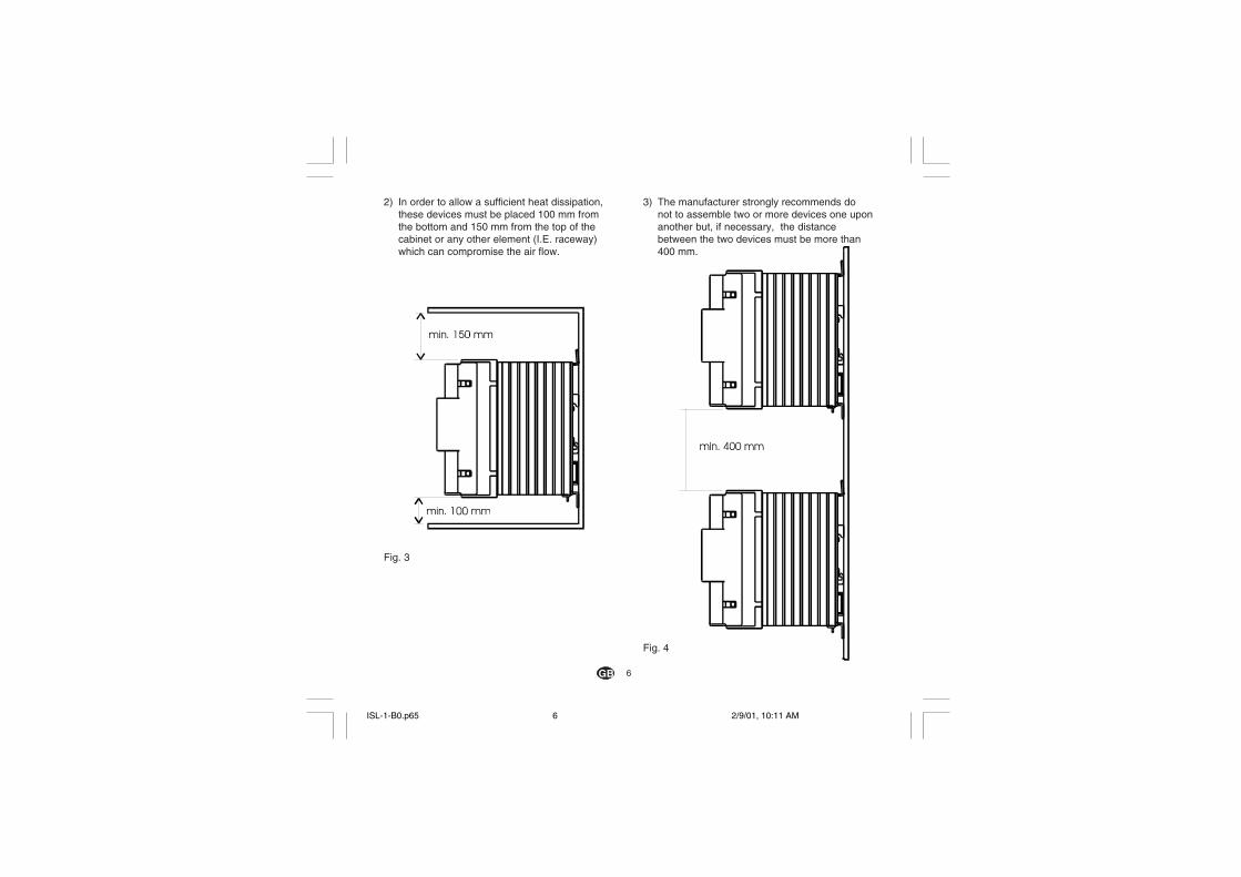
3) The manufacturer strongly recommends donot to assemble two or more devices one uponanother but, if necessary, the distancebetween the two devices must be more than400 mm.
Fig. 4
2) In order to allow a sufficient heat dissipation,these devices must be placed 100 mm fromthe bottom and 150 mm from the top of thecabinet or any other element (I.E. raceway)which can compromise the air flow.
Fig. 3
ISL-1-B0.p65 2/9/01, 10:11 AM6

7GB
The device can be mounted either on wall or on aOmega DIN rail.
WALL MOUNTINGFor wall mounting can be used the (A) holes.
In this case use two M4 screws (torque of 1Nmmax).
For the mounting template and the mechanicaldimensions of all models, please refer to theappropriate drawing, located in the "Mechanicaldimensions" paragraph.
OMEGA DIN RAIL MOUNTINGFor rail mounting use an Omega DIN rail inaccordance with EN 50 022 (35 x 7.5 mm or 35 x15 mm) regulations.
MOUNTING
Fig. 5
OmegaDIN rail
ISL-1-B0.p65 2/9/01, 10:11 AM7

8GB
CONNECTION DIAGRAMS
GENERAL NOTES FOR WIRING
WARNINGS:1) The wiring must be executed only after the device
has been correctly mounted.2) Before connecting the device, be sure that
power line voltage value is less or equal thenominal value reported on the device'sidentification label.
3) Before connecting the device, be sure that theload current (see Power � nominal currentconversion paragraph) is less or equal thedevice nominal current as a function of theambient temperature and the Duty cycle (seeTrend of the nominal current in relation withthe ambient temperature and duty cycleparagraph).
4) Before executing any operations, be absolutelysure that the device is disconnected from thepower line through the circuit breaker.
5) Use copper wires only.6) Pay attention to the input command polarity;
terminal 5 is the positive one while terminal 6 isthe negative one.
7) The neutral (if used) must be connected to the 2and 4 terminals.
8) The power input IS NOT fuse protected; placean external fuse selected among the typesshown in Table 1.NOTE:The Manufacturer decline any responsibility forinjury and/or property damage if NO fuse orfuse not included in Table 1 is used.The warranty validity also depends on it.
REMOVING
Fig. 6
For the mechanical dimensions of all models,please refer to the proper drawing (seeAppendix A).
screwdriver
ISL-1-B0.p65 2/9/01, 10:11 AM8

9GB
Table 1
ISL Fuse
Model Manuf. model
Ferraz 6600CPURGA22X58/32
25 - 400 Bussmann FWP.32A.22F
Gould 52443
Ferraz 6600CPURGA22X58/50
35 - 400 Bussmann FWP.50A.22F
Gould 53251
Ferraz 6600CPURGA22X58/50
45 - 400 Bussmann FWP.50A.22F
Gould 53251
Ferraz 6600CPURGA22X58/80
60 - 400 Bussmann FWP.80A.22F
Gould 53259
Ferraz 6600CPURGA22X58/100
80 - 400 Bussmann FWP.100A.22F
Gould 53263
25 - 600 Ferraz 6600CPURD22X58/32
35 - 600 Ferraz 6600CPURD22X58/50
45 - 600 Ferraz 6600CPURD22X58/50
60 - 600 Ferraz 6600CPURD22X58/80
80 - 600 Ferraz 6600CPURD22X58/100
9) To connect the devices to the power line, useappropriate sized wires with 75 °C (167 °F)minimum temperature rating. The following tableshows the recommended sizes:
Nominal � wires AWGcurrent (mm2)25 A 4 1235 A 6 1045 A 10 860 A 16 680 A 25 (*) 4
(*) without wire terminal
10)The tightening torque for terminals 1, 2, 3,4 and earth is:- for ISL 25 and 35 A
max = 0.8 Nmsuggested = 0.7 Nm
- for ISL 45, 60 and 80 Amax = 2 Nmsuggested = 1.5 Nm
11) The tightening torque for terminals 5 and 6 is:max = 0.5 Nmsuggested = 0.33 Nm
12) The control input is fuse protected by anSMD fuse type F, 63 V 63 mA.
ISL-1-B0.p65 2/9/01, 10:11 AM9

10GB
Power � nominal current conversionIn order to have a quick check of the deviceworking conditions, the formulas to calculate thenominal current for each device in relation to thetotal power and the connection type are provided.Preliminary notes:1) Only a resistive load must be applied to the
device, so in the following formulas the cos �will be considered equal to 1.
2) the formulas related with the 3-phaseapplications are referred to a balanced3-phase system only.
Single-phase connection
IP
VRMSRMS
=
where:P = power (in Watts).V
RMS = phase to neutral or phase to phasevoltage (in Volts)
IRMS
= nominal current (in Amperes)
Fig. 7 TERMINAL BLOCK
ISL-1-B0.p65 2/9/01, 10:11 AM10

11GB
3 -phase without neutral connection (star ordelta application)
IP
VRMS
RMS
=·3
where:P = Total load power (in Watts).VRMS = phase to phase voltage (in Volts)IRMS = nominal current (in Amperes)
3-phase with neutral connection (starapplication)
IP
VRMSRMS
=·3
where:P = Total load power (in Watts).VRMS = phase to neutral voltage (in Volts)IRMS = nominal current (in Amperes)
ISL-1-B0.p65 2/9/01, 10:11 AM11
12GB
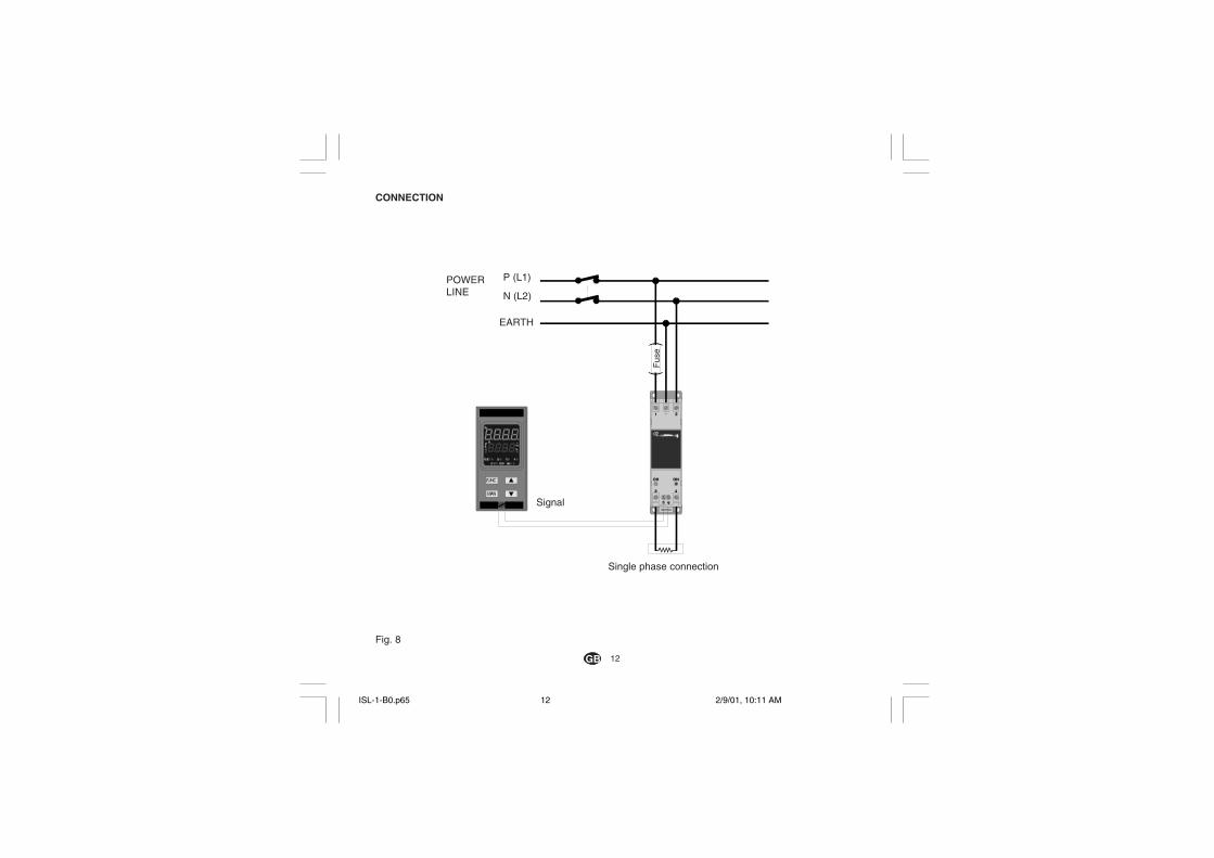
Fig. 8
P (L1)
N (L2)
EARTH
POWERLINE
Signal
Single phase connection
Fus
e
CONNECTION
ISL-1-B0.p65 2/9/01, 10:11 AM12

13GB
GENERAL SPECIFICATIONS
Mounting: rear-of-board on wall or omega DINrail.Terminals: screw terminals with front access.Load type: resistive.Min. holding current: 50 mA RMS.Leakage current: 10 mA RMS.Min. latching voltage: 40 VVoltage drop on power semiconductor: 1.2 V.Control input type: 4 to 20 mA linear.Insulation:- between power circuit and earth: 3000 V RMS
for 1 second.- between command and power circuits:
7500 Vpk
Insulation resistance:for ISL 400 V models is > 1 M� at 500 V DCfor ISL 600 V models is > 2 M� at 500 V DCOperational temperature: from 0 to 50 °C(from 32 to 122 °F).Humidity: from 20 % to 85 % RH non condensing.Storage temperature: from - 20 to + 70 °C(-4 to 158 °F)Protection: IP 20.
Thermal protectionWhen the heat sink temperature exceeds thethreshold of the thermal protection, a circuit-breaker inhibits the command signal and enablesthe OH LED indication.When the heat sink temperature goes under thethreshold of the thermal protection minushysteresis, the command signal is enabled againand the OH LED is turned OFF.
CE MARKINGThese devices are conforming to the89/336/EEC and 93/68/EEC council directives forElectromagnetic compatibility (referenceharmonized standard EN-50081-2 for Emissionsand EN-50082-2 for Immunity) and to the73/23/EEC and 93/68/EEC for Low Voltage(Standard reference UL508 part VIIIand CEI EN50178).
Installation category: IIPollution Degree: 2
ISL-1-B0.p65 2/9/01, 10:11 AM13

14GB
MODEL
CHARACTERISTICS
Nominal voltage
Nominal current(@ 50 °C)
Non-rep. surge current
I2t for fusing (10 ms)
Non-rep. peak voltage
�V/�t
PRV
Total power dissipation (I = Inom)
Weight
Amp. - V
25-400
400 V
25 A
280 A
550
1300 V
500 V/�s
1200 V
30 W
630 g
Amp. - V
35-400
400 V
35 A
400 A
860
1300 V
500 V/�s
1200 V
45 W
630 g
Amp. - V
45-400
400 V
45 A
400 A
860
1300 V
500 V/�s
1200 V
55 W
900 g
Amp. - V
60-400
400 V
60 A
1200 A
10180
1300 V
500 V/�s
1200 V
75 W
1100 g
Amp. - V
80-400
400 V
80 A
1200 A
10180
1300 V
500 V/�s
1200 V
100 W
2000 g
CHARACTERISTICS OF ISL MODELS
MODEL
CHARACTERISTICS
Nominal voltage
Nominal current(@ 50 °C)
Non-rep. surge current
I2t for fusing (10 ms)
Non-rep. peak voltage
�V/�t
PRV
Total power dissipation (I = Inom
)
Weight
Amp. - V
25-600
600 V
25 A
280 A
550
1700 V
1000 V/�s
1600 V
30 W
630 g
Amp. - V
35-600
600 V
35 A
400 A
860
1700 V
1000 V/�s
1600 V
45 W
630 g
Amp. - V
45-600
600 V
45 A
400 A
860
1700 V
1000 V/�s
1600 V
55 W
900 g
Amp. - V
60-600
600 V
60 A
1200 A
10180
1700 V
1000 V/�s
1600 V
75 W
1100 g
Amp. - V
80-600
600 V
80 A
1200 A
10180
1700 V
1000 V/�s
1600 V
100 W
2000 g
ISL-1-B0.p65 2/9/01, 10:11 AM14

15GB
MAINTENANCE
WARNING:1) Before executing any maintenance operation
on the device, on the load or on theirconnections, disconnect it from the power lineby a mechanical circuit breaker.
2) The protection degree of these devices isequal to IP 20 (according to CEI EN 60529)and they are connected to dangerous powerlines, for these reasons:- installation, wiring and maintenance must be
executed by qualified personnel;- all warnings contained in this manual must
be complied.3) Do not execute any dielectric strength or
insulation resistance test on the powerterminals.These types of test could damage the powersemiconductors.
4) During continuous operation, the heat sink couldreach a temperature higher than 80 °C (176 °F)Before execute any operation on the device,be sure that its temperature has decreased toan acceptable value.
MAINTENANCE1) REMOVE POWER FROM THE DEVICE BY
USING A MECHANICAL CIRCUIT BREAKER2) Using a vacuum cleaner or a compressed air
jet (max. 5 kg/cm2) remove all deposit of dustand dirt which may be present on the heat sinkand on the terminals.
3) To clean external plastic or rubber parts useonly a cloth moistened with:- Ethyl Alcohol (pure or denatured) [C2H5OH] or- Isopropil Alcohol (pure or denatured)[(CH3)2CHOH] or- Water (H2O)
4) Verify that there are no loose terminals (seeparagraph GENERAL NOTES FOR WIRING).
5) Before switching the power ON, be sure thatthe device is perfectly dry.
6) Turn the power ON.
ISL-1-B0.p65 2/9/01, 10:11 AM15
16GB
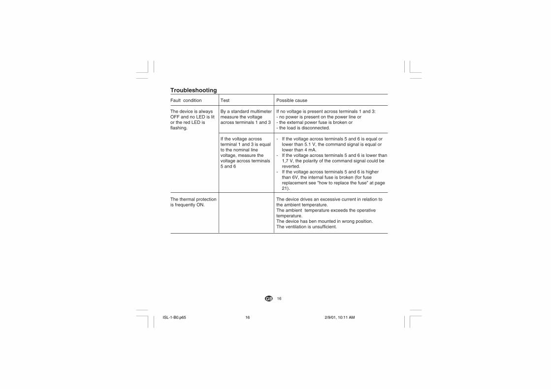
Troubleshooting
Fault condition
The device is alwaysOFF and no LED is litor the red LED isflashing.
The thermal protectionis frequently ON.
Possible cause
If no voltage is present across terminals 1 and 3:- no power is present on the power line or- the external power fuse is broken or- the load is disconnected.
- If the voltage across terminals 5 and 6 is equal orlower than 5.1 V, the command signal is equal orlower than 4 mA.
- If the voltage across terminals 5 and 6 is lower than1,7 V, the polarity of the command signal could bereverted.
- If the voltage across terminals 5 and 6 is higherthan 6V, the internal fuse is broken (for fusereplacement see "how to replace the fuse" at page21).
The device drives an excessive current in relation tothe ambient temperature.The ambient temperature exceeds the operativetemperature.The device has ben mounted in wrong position.The ventilation is unsufficient.
Test
By a standard multimetermeasure the voltageacross terminals 1 and 3
If the voltage acrossterminal 1 and 3 is equalto the nominal linevoltage, measure thevoltage across terminals5 and 6
ISL-1-B0.p65 2/9/01, 10:11 AM16

17GB
HOW TO REPLACE THE FUSE
WARNING:l) Before executing any maintenance operation,
disconnect the device from the power line by amechanical circuit breaker.
ll) During continuous operation, the heat sink couldreach a temperature higher than 80 °C (176 °F)Before executing any operation on the device,be sure that its temperature is decreased to anacceptable value.
How to remove the plastic cover.a) Lift a corner of the plastic cover inserting a
screwdriver between the plastic cover and thedevice case, close to the lock 1 as shown inthe following pictures
b) Maintaining the corner lifted, insert thescrewdriver close to the lock 2 and lift this sideof the plastic cover.
c) Repeat the point a) and b) for lock 3 and 4.
d) Remove the plastic cover.
ISL-1-B0.p65 2/9/01, 10:11 AM17

18GB
How to replace the fuse.The fuseholder is located on the vertical card (seepage 2) close to the jumper as shown below.
Using a pencil, remove the fuse from itsfuseholder as shown below.
NOTES:1) The fuse is an SMD fuse type F, 63 V 63 mA.2) The replacing fuse is supplied in a package of
5 pieces and it can be ordered to your supplierwith the order code: AISL.KIT.FUS.E00
Insert the new fuse as shown below.
Reinsert the plastic cover of the device.
Vertical card
Fuseholder
ISL-1-B0.p65 2/9/01, 10:11 AM18

1F
MONTAGE
INSTRUCTIONS:1) Ces appareils sont à même de garantir le
fonctionnement correct et répétableexclusivement si le transport, le stockage,l’installation, le raccordement et les conditionsd’utilisation sont effectués conformément auxindications de ce manuel.
2) Ces appareils ont une classe de protection IP20 (suivant CEI EN 60529) et sont raccordés àdes lignes de puissance dont la tension estdangereuse; il faut donc respecter les mesuressuivantes:- l’installation, le raccordement et l’entretien
doivent être effectués par du personnelqualifié;
- il faut respecter toutes les recommandationsindiquées dans ce manuel.
3) Il ne faut pas effectuer des essais de rigiditédiélectrique ou d’isolement sur les bornes depuissance. De tels types d’essais peuvent en-dommager les semi-conducteurs de puissance.
4) Disjoncteur mécanique:- un interrupteur ou un disjoncteur mécanique doit
être introduit entre l’équipement et la ligne;- il doit se trouver à proximité de l’appareil et
l’opérateur doit pouvoir y accéder facilement;- il doit être marqué comme le dispositif de
coupure de l’appareil.NOTE: un seul interrupteur ou disjoncteur peutcommander plusieurs appareils.
5) Avant d’effectuer toute opération sur la chargeou sur les raccordements vers la charge, véri-fier que l’appareil est débranché de la ligne viale disjoncteur mécanique.
6) Au cours le fonctionnement normal de l’appa-reil, le dissipateur de chaleur peut dépasser80°C (176°F).Avant d’effectuer toute opération sur l’appareil,vérifier que la température du dissipateur des-cend à des niveaux acceptables.
7) Choisir une position de montage propre, d’ac-cès facile et autant que possible exempte devibrations.
8) La température ambiante doit être compriseentre 0 et 50°C (de 32 à 122°F).
ISL-2-B0.p65 2/9/01, 10:29 AM1

2F
Cycle unique
3) Enlever du couvercle les bandes en carton4) Introduire le couvercle sur l’appareil en
appuyant jusqu’à l’enclenchement des butéesmécaniques.
PROGRAMMATION MATERIAL PRELIMI-NAIRE
L’appareil est fourni avec le couvercle noncomplètement monté et avec deux bandes en
Carte verticale
Bornes d’entrée
carton introduites entre le couvercle et l’appareil.1) Soulever le couvercle
On peut ainsi repérer la carte verticale
2) Sélectionner le dialogue utilisateur enprogrammant le pontet intérieur comme suit:
Cycle rapide(standard)
couvercle
bandes encarton
ISL-2-B0.p65 2/9/01, 10:30 AM2

3F
Quand l’état cycle rapide est sélectionné, l’appa-reil détecte automatiquement la fréquence de ligneet programme un temps de cycle égal à 100 pério-des de la ligne (une période est égale à 20 msquand la fréquence de ligne est égale à 50 Hz, ou16,6 ms quand la fréquence de ligne est égale à60 Hz).L’appareil peut ainsi sélectionner automatique-ment le temps de cycle mini. à même de garantirune précision égale à 1%.
NOTES CONCERNANT LES DIALOGUESUTILISATEURSCet appareil peut travailler de deux façons diffé-rentes: cycle rapide et cycle unique.
Cycle rapideCe dialogue utilisateur se base sur le concept demaintenir un temps de cycle fixe en modulant lespériodes ON et OFF (temps de cycle = périodesON + OFF).
Ingresso
Stato
Uscitain %
Tempo
Uscita
Periodi
Periodi
Periodi
Periodi
Tempo
Entrée
Etat
Sortie
PériodesTemps
Périodes
Sortie
Temps
Périodes Périodes
ISL-2-B0.p65 2/9/01, 10:30 AM3

4F
Cycle uniqueCe dialogue utilisateur réduit strictement le tempsde cycle.La période est prise comme temps de base et l’al-gorithme module le temps de cycle en modifiant lapériode ON ou la période OFF.A 50% on obtient le temps mini. de cycle qui estégal à 2 périodes (une ON et une OFF).
Ingresso
Uscitain %
Stato Stato Stato
Entrée
Sortie
NOTE :1 période est égale à:- 20 ms quand la
fréquence de ligneest égale à 50 Hz
- 16,6 ms quand lafréquence de ligneest égale à 60 Hz.
de 0 à A1 = 1 périodede 0 à B1 = 4 périodes
Sortie
Temps Temps Temps
Temps Temps Temps
Etat Etat EtatEtat
Sortie Sortie
de 0 à A2 = 1 périodede 0 à B2 = 2 périodes
de 0 à A3 = 3 périodede 0 à B3 = 4 périodes
ISL-2-B0.p65 2/9/01, 10:30 AM4

5F
NORMES GENERALES POUR LE MONTAGE
1) Les appareils doivent être montés verticale-ment ou avec une inclinaison maxi. de 20°
Fig. 1
Fig. 2
ISL-2-B0.p65 2/9/01, 10:30 AM5

6F
3) On déconseille vivement de superposer deuxou plus de deux appareils; le cas échéant, ilfaut absolument maintenir une distance supé-rieure à 400 mm entre les deux appareils.
Fig. 4
2) Les appareils doivent être montés à 100 mmau moins du fond et à 150 mm au moins duplafond de l’armoire dans laquelle ils sontinstallés. Ces mêmes distances doivent êtremaintenues en cas de goulottes ou d’autreséléments qui peuvent limiter la ventilation del’instrument.
Fig. 3
ISL-2-B0.p65 2/9/01, 10:30 AM6

7F
L’instrument peut être monté au mur ou sur unebarre Omega DIN.
MONTAGE MURALPour le montage au mur utiliser les trous (A)
Dans ce cas, nous recommandons d’utiliser deuxvis M4 serrées à un couple mini. de 1 Nm.
Pour les gabarits de perçage et les dimensionsd’encombrement, se référer au dessin mécaniquespécifique.Les dessins mécaniques de tous les modèles sontindiqués au paragraphe DIMENSIONS ET PER-ÇAGES.
MONTAGE AU MOYEN D’UNE BARRE OMEGAPour la montage sur barre, utiliser les rails OmegaDIN conformément à la spécification technique EN50 022 (35 x 7,5 mm ou 35 x 15 mm).
MONTAGE
Fig. 5
BarreOmegaDIN
ISL-2-B0.p65 2/9/01, 10:30 AM7

8F
RACCORDEMENTS ELECTRIQUES
NOTES GENERALES POUR LE RACCORDE-MENTINSTRUCTIONS:1) Les raccordements électriques ne doivent être
effectués que si l’instrument est correctementmonté.
2) Avant de raccorder l’instrument au réseau, véri-fier que la tension de ligne correspond aux indi-cations de la plaque signalétique de l’instrument.
3) Avant de raccorder l’instrument au réseau, vérifierque le courant utilisé par la charge (voir paragrapheLa conversion de puissance � courantnominal) est inférieur au courant nominal del’appareil en fonction de la température ambiante etdu cycle de fonctionnement (voir le paragrapheCourbe du courant nominal en fonction de lavariation de la température ambiante et ducycle de fonctionnement).
4) Avant de commencer toute opération de raccor-dement, vérifier que la ligne est coupée aumoyen du disjoncteur mécanique.
5) Utiliser exclusivement des conducteurs en cui-vre.
6) Faire attention à la polarité des bornes du signald’entrée ; la borne 5 est positive et la borne 6 estnégative.
7) Si la connexion au fil de neutre est prévue, leraccorder aux bornes 2 et 4.
8) L’entrée de puissance N’EST PAS protégée parun fusible; il faut donc en prévoir un à l’extérieuren le choisissant parmi ceux qui sont indiquéssur la Tableau 1.NOTE: La société décline toute responsabilité encas de dommages aux personnes ou aux choses,provoqués par l’utilisation de ces appareils avecdes fusibles différents de ceuxqui sont indiqués
ENLEVEMENT
Fig. 6
Pour les dimensions d’encombrement, se référerau dessin mécanique spécifique.Les dessins mécaniques de tous les modèles sontindiqués au paragraphe DIMENSIONS ET PER-CAGES (Appendix A).
Tournevis
ISL-2-B0.p65 2/9/01, 10:30 AM8
9F
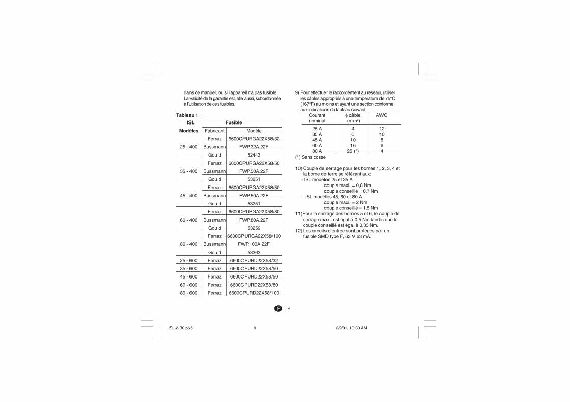
9) Pour effectuer le raccordement au réseau, utiliserles câbles appropriés à une température de 75°C(167°F) au moins et ayant une section conformeaux indications du tableau suivant:
Courant � câble AWGnominal (mm2)
25 A 4 1235 A 6 1045 A 10 860 A 16 680 A 25 (*) 4
(*) Sans cosse
10) Couple de serrage pour les bornes 1, 2, 3, 4 etla borne de terre se référant aux:
- ISL modèles 25 et 35 Acouple maxi. = 0,8 Nmcouple conseillé = 0,7 Nm
- ISL modèles 45, 60 et 80 Acouple maxi. = 2 Nmcouple conseillé = 1,5 Nm
11)Pour le serrage des bornes 5 et 6, le couple deserrage maxi. est égal à 0,5 Nm tandis que lecouple conseillé est égal à 0,33 Nm.
12) Les circuits d’entrée sont protégés par unfusible SMD type F, 63 V 63 mA.
dans ce manuel, ou si l'appareil n'a pas fusible.La validité de la garantie est, elle aussi, subordonnéeà l’utilisation de ces fusibles.
Tableau 1
ISL Fusible
Modèles Fabricant Modèle
Ferraz 6600CPURGA22X58/32
25 - 400 Bussmann FWP.32A.22F
Gould 52443
Ferraz 6600CPURGA22X58/50
35 - 400 Bussmann FWP.50A.22F
Gould 53251
Ferraz 6600CPURGA22X58/50
45 - 400 Bussmann FWP.50A.22F
Gould 53251
Ferraz 6600CPURGA22X58/80
60 - 400 Bussmann FWP.80A.22F
Gould 53259
Ferraz 6600CPURGA22X58/100
80 - 400 Bussmann FWP.100A.22F
Gould 53263
25 - 600 Ferraz 6600CPURD22X58/32
35 - 600 Ferraz 6600CPURD22X58/50
45 - 600 Ferraz 6600CPURD22X58/50
60 - 600 Ferraz 6600CPURD22X58/80
80 - 600 Ferraz 6600CPURD22X58/100
ISL-2-B0.p65 2/9/01, 10:30 AM9

10F
La conversion puissance���courant nominalPour permettre de vérifier rapidement les condi-tions de fonctionnement de l’appareil, nous repor-tons ci-après les formules devant être appliquéespour calculer le courant nominal de chaque bran-che de charge en fonction de la puissance totalede la charge et du type de raccordement.Avant-propos:1)La charge appliquée doit être purement
résistive; dans les formules suivantes le cos fsera donc égal à 1.
2)Naturellement, les formules relatives aux raccor-dements triphasés se réfèrent uniquement auxcharges équilibrées.
Raccordement monophasé
IP
VRMSRMS
=
où:P = puissance (exprimée en Watt)VRMS = tension phase-neutre ou phase-phase
(exprimée en volt)IRMS = courant nominal (exprimé en Ampères).
Fig. 7 BORNIER
ISL-2-B0.p65 2/9/01, 10:30 AM10

11F
Raccordement en étoile ou en triangle(triphasé sans neutre)
IP
VRMS
RMS
=·3
où:P = puissance totale de la charge (exprimée en
Watt)VRMS = tension phase-phase (exprimée en Volt)IRMS = courant nominal (exprimé en Ampères)
Raccordement triphasé avec neutre (étoileavec neutre)
IP
VRMSRMS
=·3
où:P = puissance totale de la charge (exprimée en
Watt)V
RMS = tension phase-neutre (exprimée en Volt)
IRMS
= courant nominal (exprimé en Ampères)
ISL-2-B0.p65 2/9/01, 10:30 AM11

12F
Fig. 8
P (L1)
N (L2)
Fus
ible
RACCORDEMENT
Signal decommande
Raccordement monophasé
TERRE
LIGNE
ISL-2-B0.p65 2/9/01, 10:30 AM12
13F
DONNEES TECHNIQUES COMMUNES
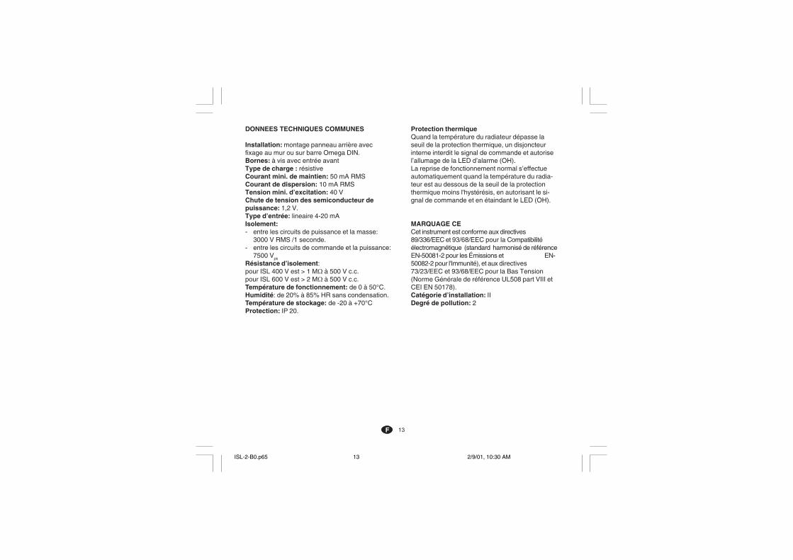
Installation: montage panneau arrière avecfixage au mur ou sur barre Omega DIN.Bornes: à vis avec entrée avantType de charge : résistiveCourant mini. de maintien: 50 mA RMSCourant de dispersion: 10 mA RMSTension mini. d’excitation: 40 VChute de tension des semiconducteur depuissance: 1,2 V.Type d’entrée: lineaire 4-20 mAIsolement:- entre les circuits de puissance et la masse:
3000 V RMS /1 seconde.- entre les circuits de commande et la puissance:
7500 Vpk
Résistance d’isolement:pour ISL 400 V est > 1 M� à 500 V c.c.pour ISL 600 V est > 2 M� à 500 V c.c.Température de fonctionnement: de 0 à 50°C.Humidité: de 20% à 85% HR sans condensation.Température de stockage: de -20 à +70°CProtection: IP 20.
Protection thermiqueQuand la température du radiateur dépasse laseuil de la protection thermique, un disjoncteurinterne interdit le signal de commande et autorisel’allumage de la LED d’alarme (OH).La reprise de fonctionnement normal s’effectueautomatiquement quand la température du radia-teur est au dessous de la seuil de la protectionthermique moins l'hystérésis, en autorisant le si-gnal de commande et en étaindant le LED (OH).
MARQUAGE CECet instrument est conforme aux directives89/336/EEC et 93/68/EEC pour la Compatibilitéélectromagnétique (standard harmonisé de référenceEN-50081-2 pour les Émissions et EN-50082-2 pour l'Immunité), et aux directives73/23/EEC et 93/68/EEC pour la Bas Tension(Norme Générale de référence UL508 part VIII etCEI EN 50178).Catégorie d’installation: IIDegré de pollution: 2
ISL-2-B0.p65 2/9/01, 10:30 AM13

14F
MODELE
CARACTÉRISTIQUES
Tension nominale
Courant nominal (@ 50°C)
Courant de crête non répétitif
I2t pour fusible (10 ms)
Tension de crête non répétitive
�V/�t
PRV
Puissance totale dissipée (I =Inom)
Poids
Amp. - V
25-400
400 V
25 A
280 A
550
1300 V
500 V/�s
1200 V
30 W
630 g
Amp. - V
35-400
400 V
35 A
400 A
860
1300 V
500 V/�s
1200 V
45 W
630 g
Amp. - V
45-400
400 V
45 A
400 A
860
1300 V
500 V/�s
1200 V
55 W
900 g
Amp. - V
60-400
400 V
60 A
1200 A
10180
1300 V
500 V/�s
1200 V
75 W
1100 g
Amp. - V
80-400
400 V
80 A
1200 A
10180
1300 V
500 V/�s
1200 V
100 W
2000 g
CARACTÉRISTIQUES DES MODELES ISL
MODELE
CARACTÉRISTIQUES
Tension nominale
Courant nominal (@ 50°C)
Courant de crête non répétitif
I2t pour fusible (10 ms)
Tension de crête non répétitive
�V/�t
PRV
Puissance totale dissipée (I =Inom
)
Poids
Amp. - V
25-600
600 V
25 A
280 A
550
1700 V
1000 V/�s
1600 V
30 W
630 g
Amp. - V
35-600
600 V
35 A
400 A
860
1700 V
1000 V/�s
1600 V
45 W
630 g
Amp. - V
45-600
600 V
45 A
400 A
860
1700 V
1000 V/�s
1600 V
55 W
900 g
Amp. - V
60-600
600 V
60 A
1200 A
10180
1700 V
1000 V/�s
1600 V
75 W
1100 g
Amp. - V
80-600
600 V
80 A
1200 A
10180
1700 V
1000 V/�s
1600 V
100 W
2000 g
ISL-2-B0.p65 2/9/01, 10:30 AM14

15F
ENTRETIEN
INSTRUCTIONS1)Avant d’effectuer toute opération d’entretien sur
l’instrument, sur la charge ou sur leursraccordements, vérifier que l’appareil soitdéconnecté de la ligne via le disjoncteurmécanique.
2)Ces appareils ont une classe de protection IP 20(suivant CEI EN 60529) et sont raccordés auxlignes de puissance sous des tensionsdangereuses; il faut donc respecter les mesuressuivantes:- l’installation, le raccordement et l’entretiendoivent être effectués par du personnelqualifié;
- il faut respecter toutes les instructionsindiquées sur ce manuel.
3)Il ne faut pas effectuer des essais de rigiditédiélectrique ou d’isolement sur les bornes depuissance. De tels types d’essais peuventendommager les semi-conducteurs depuissance.
4)Au cours du fonctionnement normal de l’appareille dissipateur de chaleur peut dépasser 80°C(176 °F).Avant d’effectuer toute opération sur l’appareil,vérifier que la température du dissipateur soit àune valeur acceptable.
ENTRETIEN ORDINAIRE
1)COUPER LA TENSION A L’APPAREIL via ledisjoncteur mécanique.
2) En utilisant un aspirateur ou un jet d’aircomprimé à basse pression (maxi. 5 kg/cm2)enlever les dépôts de poussière et de saleté surle dissipateur de chaleur et sur les bornes deraccordement.
3)Pour nettoyer les parties extérieures enplastique, utiliser exclusivement un chiffonpropre et légèrement imbibé avec:- alcool éthylique (pur ou dénaturé) [C
2H
5OH]
- alcool isopropylique (pur ou dénaturé) [CH3)
2
CHOH]- Eau (H
2O)
4) Contrôler les bornes qui ne doivent pas êtredesserrées (voir NOTES GENERALES POURLE RACCORDEMENT)
5) Avant de remettre l’appareil sous tension,vérifier que toutes les parties sont parfaitementsèches.
6)Remettre sous tension.
ISL-2-B0.p65 2/9/01, 10:30 AM15

16F
Cause probable
S’il n’y a pas de tension aux extrémités des bornes 1 et 3 :- la charge est déconnectée ou- le fusible extérieur de puissance est interrompu ou- la ligne n’est pas alimentée.
- Si la tension aux extrémités des bornes 5 et 6 estinférieure ou égale à 5,1 V, le signal de commandeest inférieur ou égal à 4 mA.
- Si la tension aux extrémités des bornes 5 et 6 estinférieure à 1,7 V, la polarité du signal de com-mande pourrait être inversé.
- Si la tension aux extrémités des bornes 5 et 6 estsupérieure à 6 V, le fusible intérieur est interrompu(pour le remplacer se reporter au chapitre “rempla-cement du fusible” page 21).
L’appareil pilote un courant excessif en fonction de latempérature ambiante.La température ambiante est supérieure à la tempéra-ture de fonctionnement.L’appareil est monté dans une position non correcte.La ventilation est insuffisante.
Condition d’erreur
L’appareil est toujoursà l’état OFF et aucuneLED n’est allumée oula LED rouge clignote.
La protection thermi-que se déclenche tropsouvent.
Essai
A l’aide d’un multimètrestandard, mesurer la ten-sion aux extrémités desbornes 1 et 3.
Si la tension aux extrémi-tés des bornes 1 et 3 estégale à la tension nomi-nale, mesurer la tensionaux extrémités des bor-nes 5 et 6.
DYSFONCTIONNEMENTS EVENTUELS
ISL-2-B0.p65 2/9/01, 10:30 AM16

17F
REMPLACEMENT DU FUSIBLE
ATTENTION :l) Avant d’effectuer toute opération d’entretien sur
les appareils, sur la charge ou sur lesraccordements, vérifier que l’appareil estdéconnecté de la ligne via le disjoncteurmécanique.
ll) Pendant le fonctionnement normal de l’appareil, ledissipateur de chaleur peut atteindre 80 °C (176 °F).Avant d’effectuer toute opération sur l’appareil,vérifier que la température du dissipateur est à unniveau acceptable.
Comment enlever le couverclea) Soulever un coin du couvercle en introduisant
la pointe d’un tournevis entre le couvercle etl’appareil près du bloc 1 (voir les figuressuivantes).
b) En continuant à soulever le coin, introduire letournevis près du bloc 2 et soulever ce côté ducouvercle.
c) Répéter les opérations décrites aux points a) etb) pour les blocs 3 et 4.
d) Soulever le couvercle.
ISL-2-B0.p65 2/9/01, 10:30 AM17

18F
Comment remplacer le fusibleLe porte-fusible se trouve sur la carte verticale(voir page 2) près des pontets (voir la figure sui-vante).
A l’aide de la pointe d’un crayon soulever le fusiblehors de son porte-fusible (voir figure suivante).NOTES:
Carteverticale
1) Le fusible (SMD en technologie) est type F, 63V 63 mA.
2) Le fusible de rechange (disponibles enemballage 5 pièces) peut être commandéau fournisseur en citant le codeAISL.KIT.FUS.E00.
Introduire le nouveau fusible suivant la figure ci-après.
Monter le couvercle sur l’appareil.
Porte-fusible
ISL-2-B0.p65 2/9/01, 10:30 AM18

1D
MONTAGE
HINWEISE:1) Diese Geräte gewährleisten den einwandfreien
und wiederholfähigen Betrieb nur unter derVoraussetzung, daß der Transport, die Lagerung,die Installation, der Anschluß, dieEinsatzbedingungen und Wartung gemäß denHinweisen in dieser Bedienungsanleitungerfolgen.
2) Der Schutzgrad dieser Geräte ist IP 20 (gemäßCEI EN 60529) und sie sind an Leistungskabelmit gefährlichen Spannungen angeschlossen.Aus diesem Grund müssen die nachstehendangeführten Punkte befolgt werden:- Installation, Anschluß und Wartung müssen
von qualifiziertem Personal durchgeführtwerden.
- Alle in dieser Bedienungsanleitung enthaltenenHinweise müssen befolgt werden.
3) An den Klemmen der Leistungskabel keineDurchschlagsfestigkeits- oderKörperschlußprüfungen durchführen.Diese Art Versuche können die Leistungs-Halbleiter schädigen.
4) Mechanischen Trenner:- Die Installation eines Schalters oder
mechanischen Trenner zwischen demGerät und der Leitung;
- Der Schalter oder Trenner muß inunmittelbarer Nähe des Geräts und für denBedienpersonal leicht erreichtbar angebrachtwerden.
- Er muß als Unterbrechungsvorrichtung desGeräts gekennzeichnet werden.
ANMERKUNG: Ein einziger Schalter oderTrenner kann mehrere Geräte steuern.
5) Vor der Durchführung von Maßnahmen jeder Artan der Last oder an den Verbindungen zur Lastüberprüfen, ob das Gerät mit dem mechanischenTrenner von der Leitung getrennt wurde.
6) Während des Normalbetriebs des Geräts kannder Kühlkörper eine Temperatur höher von80°C (176°F) erreichen.Vor der Durchführung von Maßnahmen jeder Artsicherstellen, daß die Temperatur des Kühlkörperauf annehmbare Werte gesunken ist.
7) Für die Montage eine saubere, leicht zugänglicheund wenn möglich vibrationsfreie Stelle wählen.
8) Die Umgebungstemperatur muß zwischen 0 und50° (32 und 122°F) liegen.
ISL-3-B0.p65 2/9/01, 10:15 AM1
2D
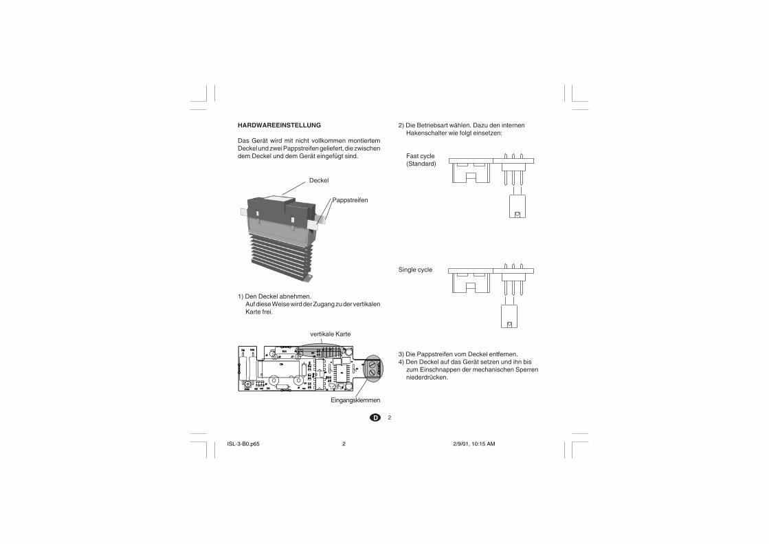
Single cycle
3) Die Pappstreifen vom Deckel entfernen.4) Den Deckel auf das Gerät setzen und ihn bis
zum Einschnappen der mechanischen Sperrenniederdrücken.
HARDWAREEINSTELLUNG
Das Gerät wird mit nicht vollkommen montiertemDeckel und zwei Pappstreifen geliefert, die zwischendem Deckel und dem Gerät eingefügt sind.
vertikale Karte
Eingangsklemmen
1) Den Deckel abnehmen.Auf diese Weise wird der Zugang zu der vertikalenKarte frei.
2) Die Betriebsart wählen. Dazu den internenHakenschalter wie folgt einsetzen:
Fast cycle(Standard)
Deckel
Pappstreifen
ISL-3-B0.p65 2/9/01, 10:15 AM2

3D
Wenn der Modus fast cycle gewählt wurde, erfaßtdas Gerät automatisch die Leitungsfrequenz undstellt eine Zykluszeit ein, die 100 Perioden der Leitungentspricht (eine Periode = 20 ms, wenn dieLeitungsfrequenz gleich 50 Hz ist, oder 16,6 ms,wenn die Leitungsfrequenz gleich 60 Hz ist). Aufdiese Art wählt das Gerät automatisch die kürzesteZykluszeit, die zur Gewährleistung einer Genauigkeitvon 1%erforderlich ist.
ANMERKUNGEN ZU DEN BETRIEBSARTENDieses Gerät kann auf 2 verschiedene Arten arbeiten:fast cycle und single cycle.
Fast cycleDieser Betriebsart beruht auf dem Konzept:Beibehaltung einer feststehenden Zykluszeit durchdie Modulation der ON-und OFF-Perioden(Zykluyszeit = ON- + OFF-Perioden).
Ingresso
Stato
Uscitain %
Tempo
Uscita
Periodi
Periodi
Periodi
Periodi
Tempo
Eingang
Status
Ausgang
Perioden
Zeit
Perioden
PeriodenPerioden
Zeit
Ausgang
ISL-3-B0.p65 2/9/01, 10:15 AM3
4D
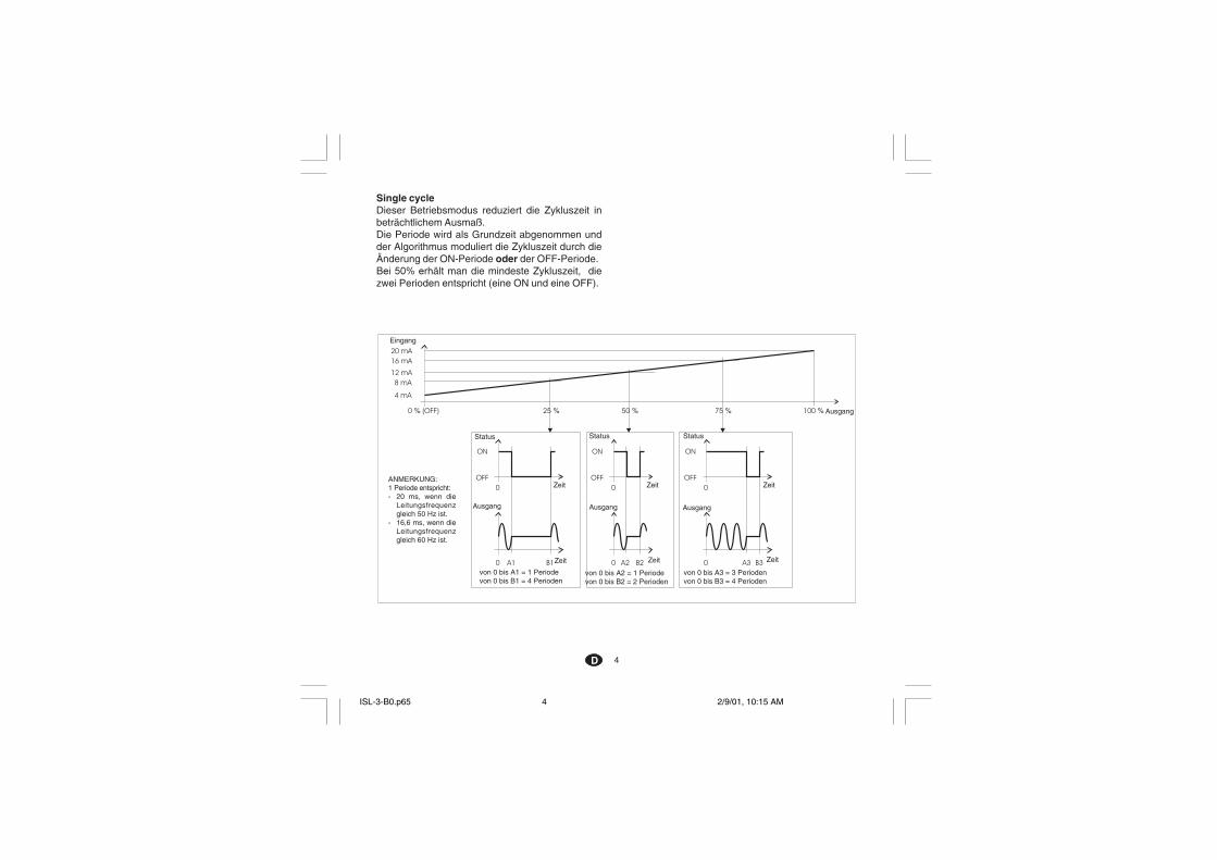
Single cycleDieser Betriebsmodus reduziert die Zykluszeit inbeträchtlichem Ausmaß.Die Periode wird als Grundzeit abgenommen undder Algorithmus moduliert die Zykluszeit durch dieÄnderung der ON-Periode oder der OFF-Periode.����������ält man die mindeste Zykluszeit, diezwei Perioden entspricht (eine ON und eine OFF).
Eingang
Ausgang
Status
Zeit
Ausgang
Status Status
Ausgang Ausgang
Zeit Zeit
Zeit Zeit Zeit
von 0 bis A1 = 1 Periodevon 0 bis B1 = 4 Perioden
von 0 bis A2 = 1 Periodevon 0 bis B2 = 2 Perioden
von 0 bis A3 = 3 Periodenvon 0 bis B3 = 4 Perioden
ANMERKUNG:1 Periode entspricht:- 20 ms, wenn die
Leitungsfrequenzgleich 50 Hz ist.
- 16,6 ms, wenn dieLeitungsfrequenzgleich 60 Hz ist.
ISL-3-B0.p65 2/9/01, 10:15 AM4
5D
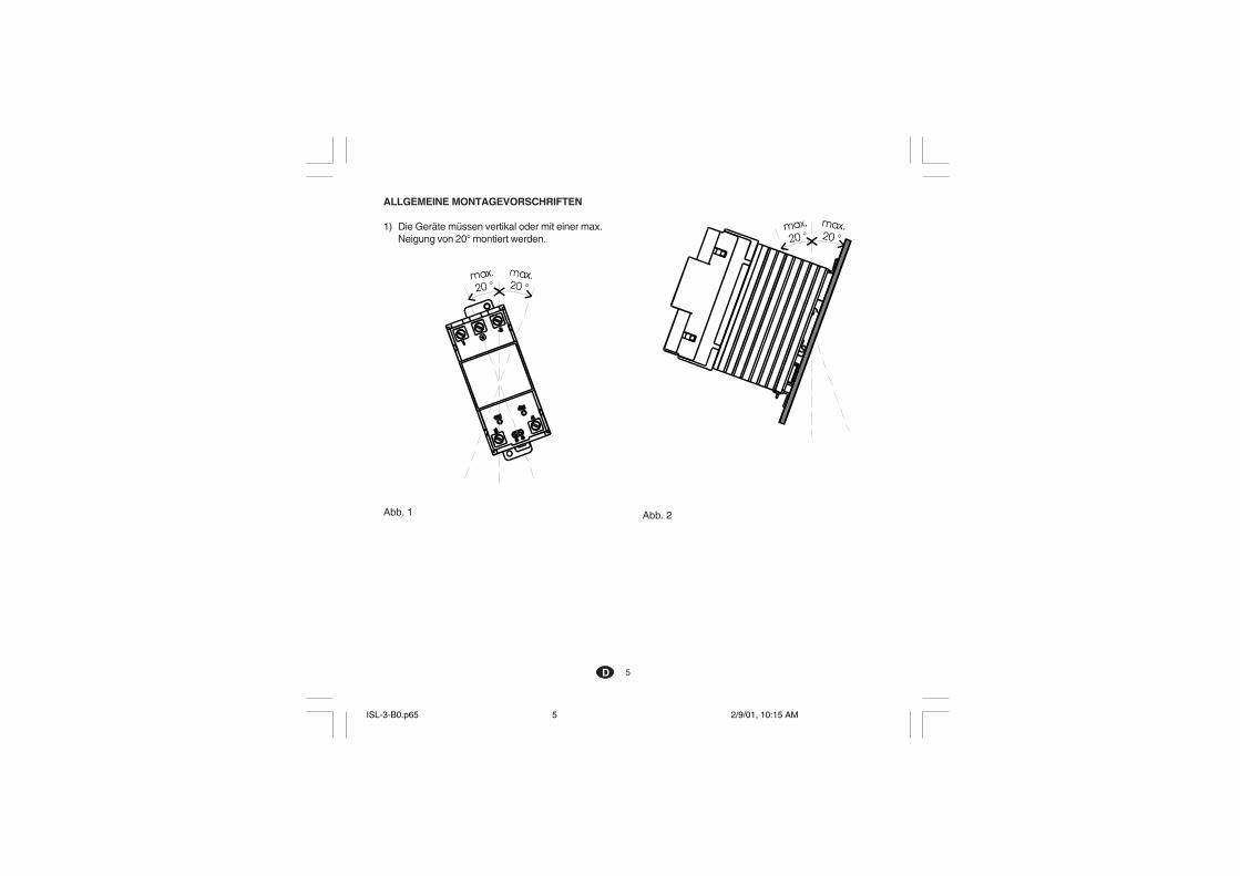
ALLGEMEINE MONTAGEVORSCHRIFTEN
1) Die Geräte müssen vertikal oder mit einer max.Neigung von 20° montiert werden.
Abb. 1 Abb. 2
ISL-3-B0.p65 2/9/01, 10:15 AM5

6D
3) Es wird nachdrücklich davon abgeraten, zweioder mehrere Geräte übereinander zumontieren. Falls es jedoch unbedingterforderlich ist, muß der Abstand zwischen denbeiden Geräten mehr als 400 mm betragen.
Abb. 4
2) Die Geräte müssen mindestens 100 mm vomBoden und mindestens 150 mm von der Deckedes Schranks, in dem sie installiert sind,entfernt sein.Dieselben Abstände müssen auch zu eventuellvorhandenen Führungen oder Elementen, diedie Belüftungs des Geräts einschränkenkönnen, eingehalten werden.
Abb. 3
ISL-3-B0.p65 2/9/01, 10:15 AM6

7D
Das Gerät kann an der Wand oder auf einerDIN-Omega-Schiene montiert werden.
WANDMONTAGEFür die Wandmontage die Bohrungen verwenden (A)
In diesem Fall wird die Verwendung von zwei M4-Schrauben empfohlen, die mit einem min.Anziehmoment von 1 Nm festgezogen werden.Für die Ausschnitte und Außenmaße auf diespezifische Mechanikzeichnung Bezug nehmen.Die Mechanikzeichnungen für alle Modelle sind indem Abschnitt ABMESSUNGEN abgebildet(Appendix A).
MONTAGE AUF OMEGA-SCHIENEFür die Schienenmontage DIN-Omegaführungenverwenden, die mit der EN-Norm 50 022übereinstimmen (35 x 7,5 mm oder 35 x 15 mm).
MONTAGE
Abb. 5
DINOmega-Schiene
ISL-3-B0.p65 2/9/01, 10:15 AM7

8D
ELEKTRISCHE ANSCHLÜSSE
ALLGEMEINE ANMERKUNGEN ZUMANSCHLUSS.HINWEISE:1) Die Anschlüsse müssen ausgeführt werden,
nachdem das Gerät korrekt montiert wurde.2) Vor dem Anschluß des Geräts an das Netz, sich
vergewissern, daß die Leitungsspannung nichtden auf dem Kennschild des Geräts angegebenenNennwert übersteigt.
3) Vor dem Anschluß des Geräts an das Netz, sichvergewissern, daß der Laststrom (siehe Abschnitt“Die Umformung Leistung � Nennstrom”)niedriger als der Nennstrom des Geräts inFunktion der Umgebungstempera-tur und desBetriebszyklus ist (siehe Abschnitt“Nennstromkurve bei Änderung der Umge-bungstemperatur und des Betriebszyklus”).
4) Vor der Ausführung der Anschlüsse, überprüfen,ob die Leitung mit dem mechanischen Trennerunterbrochen wurde.
5) Nur Kupferleiter verwenden.6) Die Polung der Anschlußklemmen des
Eingangssiganals beachten; dieAnschlußklemme 5 ist positiv; dieAnschlußklemme 6 negativ.
7) Wenn der Anschluß an den Sternpunktleitervorgesehen ist, den Leiter an die Klemmen 2 und4 anschließen.
8) Der Leistungseingang ist NICHT durch eine Sicherunggeschützt. Es muß daher eine externe Sicherungvorgesehen werden (die Sicherung aus der Tabelle 1).ANMERKUNG:Der Hersteller lehnt jeglicheVerantwortung für Schäden an Dingen oder Personenab, die auf den Einsatz dieser Geräte ohneSicherungen oder mit Sicherungen zurückzuführensind, die sich von den in dieser Bedienungsanleitung
ENTFERNUNG
Abb. 6
Für die Außenmaße auf die spezifischeMechanikzeichnung Bezug nehmen.Die Mechanikzeichnungen für alle Modelle sind indem Abschnitt ABMESSUNGEN abgebildet(Appendix A).
Schraubezieher
ISL-3-B0.p65 2/9/01, 10:15 AM8

9D
9) Für den Netzanschluß Kabel verwenden, diefür eine Temperatur von mindestens 75°C(167°F) geeignet sind und deren Querschnittden Angaben in der folgenden Tabelleentspricht:
Nennstrom � Kabel AWG(mm2)
25 A 4 1235 A 6 1045 A 10 860 A 16 680 A 25 (*) 4
(*) Ohne Kabelverbinder
10)Anziehmoment für die Klemmen 1, 2, 3, 4, undErdungsklemme bezogen auf:- für alle Modelle ISL 25 und 35 A:
max. Anziehmoment = 0,8 Nm.empfohlenes Anziehmoment = 0,7 Nm.
- für ISL Modelle 45, 60 und 80 Amax. Anziehmoment = 2 Nm.empfohlenes Anziehmoment = 1,5 Nm
11) Für die Klemmen 5 und 6 ist das max.Anziehmoment 0,5 Nm, das empfohleneMoment gleich 0,33 Nm.
12) Die Eingangsschaltungen sind durch eineSMD-Sicherung; Typ F, 63 V, 63 mAgeschützt.
genannten Sicherungen unterscheiden. Auch dieGültigkeit der Garantie ist von der Verwendung dergenannten Sicherungen abhängig
Tabelle1
ISL Sicherung
Typ Herst. Modell
Ferraz 6600CPURGA22X58/32
25 - 400 Bussmann FWP.32A.22F
Gould 52443
Ferraz 6600CPURGA22X58/50
35 - 400 Bussmann FWP.50A.22F
Gould 53251
Ferraz 6600CPURGA22X58/50
45 - 400 Bussmann FWP.50A.22F
Gould 53251
Ferraz 6600CPURGA22X58/80
60 - 400 Bussmann FWP.80A.22F
Gould 53259
Ferraz 6600CPURGA22X58/100
80 - 400 Bussmann FWP.100A.22F
Gould 53263
25 - 600 Ferraz 6600CPURD22X58/32
35 - 600 Ferraz 6600CPURD22X58/50
45 - 600 Ferraz 6600CPURD22X58/50
60 - 600 Ferraz 6600CPURD22X58/80
80 - 600 Ferraz 6600CPURD22X58/100
ISL-3-B0.p65 2/9/01, 10:15 AM9

10D
Die Umformung Leistung���NennstromUm eine rasche Überprüfung derBetriebsbedingungen des Geräts zu ermöglichen,werden im folgenden die Formeln wiedergegeben,die zur Berechnung des Nennstroms jedesLastzweigs in Funktion der Gesamtleistung undder Art des Anschlusses dienen.Voraussetzungen:1) Die aufgebrachte Belastung mußwinkelfrei sein und daher wird in den folgendenFormeln für cos���der Wert 1 angenommen.2) Die Formeln für die dreiphasigenAnschlüsse beziehen sich natürlich nur aufausgeglichene Belastungen.
Einphasiger Anschluß
IP
VRMSRMS
=
wobei:P = Leistung (in Watt ausgedrückt)VRMS = Spannung Phase-Sternpunktleiter oderPhase-Phase (in Volt ausgedrückt)IRMS = Nennspannung (in Ampere ausgedrückt)
Abb. 7 ANSCHLUSSBLOCK
ISL-3-B0.p65 2/9/01, 10:15 AM10

11D
Stern-oder Deltaschaltung (dreiphasig, ohneSternpunktleiter)
IP
VRMS
RMS
=·3
wobei:P = Gesamtleistung der Last (in Wattausgedrückt)VRMS = Spannung Phase-Phase (in Voltausgedrückt)IRMS = Nennspannung (in Ampere ausgedrückt)
Dreiphasiger Anschluß mit Sternpunktleiter(Sternschaltung mit Sternpunktleiter)
IP
VRMSRMS
=·3
wobei:P = Gesamtleistung der Last (in Wattausgedrückt)VRMS = Spannung Phase-Phase (in Voltausgedrückt)IRMS = Nennspannung (in Ampere ausgedrückt)
ISL-3-B0.p65 2/9/01, 10:15 AM11

12D
Abb. 8
P (L1)
N (L2)
ANSCHLÜSSE
LEITUNG
ERDE
Steuersignal
Einphasiger Anschluß
Sic
heru
ng
ISL-3-B0.p65 2/9/01, 10:15 AM12

13D
ALLGEMEINE TECHNISCHE DATEN
Installation: Schalttafelmontage mit Befestigungan der Wand oder an DIN-Omega-Schiene.Klemmen: Schraubklemmen mit frontalemZugangArt der Belastung: durch WiderstandMin. Haltestrom: 50 mA RMSLeckstrom: 10 mA RMSMin. Ansprechspannung: 40 VSpannungsabfall Leistungshalbleiter: 1,2 V.Eingangsart: Lineareingänge 4-20 mAIsolierung:- zwischen Leistungskreisen und Erde: 3000 V eff.
für 1 Sekunde.- zwischen Steuerkreisen und Leistung: 7500 Vpk
Isolationswiderstand:für ISL 400 V und > 1 M� bei 500 V DCfür ISL 600 V und > 2 M� bei 500 V DCBetriebstemperatur: von 0 bis 50 °C.Relative Feuchtigkeit: von 20% bis 85%, nichtkondensierend.Lagertemperatur: von -20 bis +70 °C
Schutzklasse: IP 20.Wärmeschutz:Wenn die Temperatur des Kühlkörper denSchwellenwert von dem Wärmeschutzüberschreitet, unterbricht ein interner Schalter dasSteuersignal und aktiviert die Einschaltung derAlarmled (OH). Die Wiederherstellung desNormalbetriebs erfolgt automatisch, sobald dieTemperatur unter den Schwellen wert von demWärmeschutz minus die Hysteresis sinkt, bei derAktivierung des Steuersignals und derAusschaltung der Alarmled (OH).
CE ZEICHENDieses Gerät entspricht den Richtlinien 89/336/EEC und 93/68/EEC für die ElektromagnetischeKompatibilität (in Einklang stehendeBezugsstandards EN-50081-2 für die Emissionenund EN-50082-2 für die Störfestigkeit) und denRichtlinien 73/23/EEC und 93/68/EEC für dieNiederspannung (Bezug nehmen auf die Norm UL508 Teile VIII und CEI EN 50178).Installationskategorie: IIVerschmutzungsgrad: 2
ISL-3-B0.p65 2/9/01, 10:15 AM13

14D
LEISTUNGSMERKMALE VON DEN ISL
Amp. - V
25-600
600 V
25 A
280 A
550
1700 V
1000 V/�s
1600 V
30 W
630 g
Amp. - V
35-600
600 V
35 A
400 A
860
1700 V
1000 V/�s
1600 V
45 W
630 g
Amp. - V
45-600
600 V
45 A
400 A
860
1700 V
1000 V/�s
1600 V
55 W
900 g
Amp. - V
60-600
600 V
60 A
1200 A
10180
1700 V
1000 V/�s
1600 V
75 W
1100 g
Amp. - V
80-600
600 V
80 A
1200 A
10180
1700 V
1000 V/�s
1600 V
100 W
2000 g
Amp. - V
25-400
400 V
25 A
280 A
550
1300 V
500 V/�s
1200 V
30 W
630 g
Amp. - V
35-400
400 V
35 A
400 A
860
1300 V
500 V/�s
1200 V
45 W
630 g
Amp. - V
45-400
400 V
45 A
400 A
860
1300 V
500 V/�s
1200 V
55 W
900 g
Amp. - V
60-400
400 V
60 A
1200 A
10180
1300 V
500 V/�s
1200 V
75 W
1100 g
Amp. - V
80-400
400 V
80 A
1200 A
10180
1300 V
500 V/�s
1200 V
100 W
2000 g
MODELL
LEISTUNGSMERKMALE
Nennspannung
Nennstrom (@ 50°C)
Nicht wiederholbarer Spitzenstrom
I2t pro Sicherun (10 ms)
Nicht wiederholbare Spitzenspannung
�V/�t
PRV
Aufgebrauchte Gesamtleistung �������
Gewicht
MODELL
LEISTUNGSMERKMALE
Nennspannung
Nennstrom (@ 50°C)
Nicht wiederholbarer Spitzenstrom
I2t pro Sicherun (10 ms)
Nicht wiederholbare Spitzenspannung
�V/�t
PRV
Aufgebrauchte Gesamtleistung �������
Gewicht
ISL-3-B0.p65 2/9/01, 10:15 AM14
15D
WARTUNG
HINWEISE1) Vor der Durchführung von
Wartungsmaßnahmen jeder Art an dem Gerät,an der Last oder an den Verbindungen vonbeiden, überprüfen, ob das Gerät mit demmechanischen Trenner von der Leitunggetrennt wurde
2) Der Schutzgrad dieser Geräte ist IP 20 (gemäßCEI EN 60529) und sie sind an Leistungskabelmit gefährlichen Spannungen angeschlossen.Aus diesem Grund müssen die nachstehendangeführten Punkte befolgt werden:- Installation, Anschluß und Wartung müssen
von qualifiziertem Personal durchgeführtwerden.
- Alle in dieser Bedienungsanleitungenthaltenen Hinweise müssen befolgt
werden.3) An den Klemmen der Leistungskabel keine
Durchschlagsfestigkeits- oderKörperschlußprüfungen durchführen.Diese Art Versuche können die Leistungs-Halbleiter schädigen.
4) Während des Normalbetriebs des Geräts kannder Kühlkörper eine Temperatur von 80°C(176°F) erreichen.Vor der Durchführung von Maßnahmen jeder Artsicherstellen, daß die Temperatur des Kühlkörperauf annehmbare Werte gesunken ist.
Regelmäßige Wartung
1) Mit dem mechanischen Trenner DIESPANNUNGSZUFUHR ZUM GERÄTUNTERBRECHEN.
2) Mit einem Absauger oder einem Druckluftstrahlmit niedrigem Druck (max. 5 kg/cm²) eventuellvorhandene Staub- und Schmutzablagerungenvom Wärmeableiter und von denAnschlußklemmen entfernen.
3) Zur Reinigung der äußeren Plastikteile,ausschließlich einen sauberen Lappenverwenden, befeuchtet mit:- Äthylalkohol (rein oder denaturiert) [C2H5OH]- Isopropylalkohol (rein oder denaturiert)[(CH3)2CHOH]- Wasser [H2O]
4) Den festen Sitz der Klemmen überprüfen(siehe ALLGEMEINE ANMERKUNGEN ZUMANSCHLUSS).
5) Bevor das Gerät mit Spannung versorgt wird,sich vergewissern, daß alle Teile vollkommentrocken sind.
6) Das Gerät mit Spannung versorgen.
ISL-3-B0.p65 2/9/01, 10:15 AM15
16D
Mögliche Ursache
Falls an den Enden der Anschlußklemmen 1 und 3 keineSpannung vorhanden ist:- die Last ist nicht angeschlossen oder- die externe Leistungssicherung ist unterbrochen oder- die Leitung führt keinen Strom
- Wenn die Spannung an den Enden derAnschlußklemmen 5 und 6 geringer oder gleich 5,1 Vist, ist das Steuersignal geringer oder gleich 4 mA.
- Wenn die Spannung an den Enden derAnschlußklemmen 5 und 6 unter 1,7 V liegt, könnte diePolung des Steuersignals umgekehrt sein.
- Wenn die Spannung an den Enden derAnschlußklemmen 5 und 6 über 6 V liegt, ist die interneSicherung unterbrochen (für den Austausch siehe“Austausch der Sicherung” auf Seite 21.
Das Gerät steuert einen in Bezug auf die Raumtemperaturübermäßigen Strom.Die Umgebungstemperatur ist höher als die Betriebs-temperatur.Das Gerät wurde nicht in der korrekten Stellung montiert.Die Belüftung ist unzureichend.
Fehlerbedingung
Das Gerät ist immerausgeschaltet (OFF)und keine LED leuchtetoder die rote LED blinkt.
Der Wärmeschutzspricht zu häufig an.
Prüfung
Mit einem Standard-Multi-meter die Spannung an denEnden der Anschlußklem-men 1 und 3 messen.
Wenn die Spannung anden Enden der Anschluß-klemmen 1 und 3 der Nenn-spannung gleich ist, dieSpannung an den Endender Anschlußklemmen 5und 6 messen.
LÖSUNG DER PROBLEME
ISL-3-B0.p65 2/9/01, 10:15 AM16
17D
AUSTAUSCH DER SICHERUNG
HINWEISE:l) Vor der Durchführung von Wartungsmaßnahmen
jeder Art an dem Gerät, an der Last oder an denVerbindungen zur Last, überprüfen, ob das Gerätmit dem mechanischen Trenner von der Leitunggetrennt wurde.
ll) Während des Normalbetriebs des Geräts, kann derKühlkörper eine Temperatur von 80°C (176°)erreichen.Vor der Durchführung von Maßnahmen jeder Art andem Gerät, sicherstellen, daß die Temperatur desKühlkörpers auf annehmbare Werte gesunken ist.
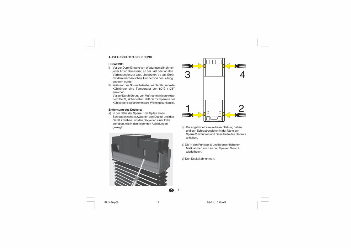
Entfernung des Deckels:a) In der Nähe der Sperre 1 die Spitze eines
Schraubenziehers zwischen den Deckel und dasGerät schieben und den Deckel an einer Eckeanheben, wie in den folgenden Abbildungengezeigt. b) Die angehobe Ecke in dieser Stellung halten
und den Schraubenzieher in der Nähe derSperre 2 einführen und diese Seite des Deckelsanheben.
c) Die in den Punkten a) und b) beschriebenenMaßnahmen auch an den Sperren 3 und 4wiederholen.
d) Den Deckel abnehmen.
ISL-3-B0.p65 2/9/01, 10:15 AM17
18D
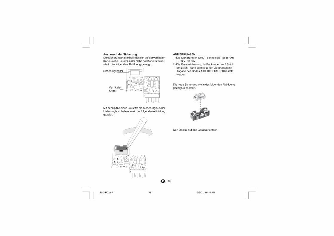
Austausch der SicherungDer Sicherungshalter befindet sich auf der vertikalenKarte (siehe Seite 2) in der Nähe der Kodierstecker,wie in der folgenden Abbildung gezeigt.
Mit der Spitze eines Bleistifts die Sicherung aus derHalterung hochheben, wie in der folgenden Abbildunggezeigt.
VertikaleKarte
ANMERKUNGEN:1) Die Sicherung (in SMD-Technologie) ist der Art
F, 63 V, 63 mA,2) Die Ersatzsicherung, (in Packungen zu 5 Stück
erhältlich), kann beim eigenen Lieferanten mitAngabe des Codes AISL.KIT.FUS.E00 bestelltwerden.
Die neue Sicherung wie in der folgenden Abbildunggezeigt, einsetzen.
Den Deckel auf das Gerät aufsetzen.
Sicherungshalter
ISL-3-B0.p65 2/9/01, 10:15 AM18

1I
MONTAGGIO
AVVERTENZE:1) Questi apparecchi sono in grado di garantire un
funzionamento corretto e ripetibile solo se iltrasporto, l'immagazzinamento, l'installazione,il collegamento e le condizioni di utilizzo e lamanutenzione vengono eseguite in conformitàalle indicazioni di questo manuale.
2) Questi apparecchi hanno una classe diprotezione IP 20 (secondo CEI EN 60529) esono collegati a linee di potenza con tensionipericolose; per queste ragioni:- l'installazione, il collegamento e la manuten-
zione deve essere eseguita da personalequalificato;
- devono essere rispettate tutte le avvertenzeriportate da questo manuale.
3) Non eseguire prove di rigidità dielettrica o diisolamento sui terminali di potenza.Queste tipologie di prove possono danneggiarei semiconduttori di potenza.
4) Disgiuntore:- un interruttore o disgiuntore meccanico deve
essere inserito tra l'apparecchiatura e la linea;- esso deve trovarsi in stretta vicinanza dell'appa-
recchio ed essere facilmente raggiungibile daparte dell'operatore;
- Deve essere marcato come il dispositivo diinterruzione dell'apparecchio.
NOTA: un singolo interruttore o disgiuntore puòcomandare più apparecchi.
5) Prima di eseguire qualsiasi operazione sul caricoo sui collegamenti verso il carico, assicurarsi chel'apparecchio sia stato disconnesso dalla lineatramite il disgiuntore meccanico.
6) Durante il normale funzionamento dell'apparec-chio il dissipatore di calore può raggiungere unatemperatura maggiore di 80 °C (176 °F).Prima di effettuare qualsiasi operazione sull'ap-parecchio, assicurarsi che la temperatura deldissipatore sia scesa a livelli accettabili.
7) Scegliere una posizione di montaggio pulita, fa-cilmente accessibile e possibilmente esente davibrazioni.
8) La temperatura ambiente deve essere compresatra 0 e 50 °C (da 32 a 122 °F).
ISL-4-B0.p65 2/9/01, 10:16 AM1

2I
2) Selezionare il modo operativo impostando ilponticello interno come segue:
Fast cycle(standard)
Single cycle
3) Rimuovere le strisce di cartone dal coperchio.4) Inserire il coperchio sull'apparecchio
premendolo fino allo scatto dei blocchimeccanici.
IMPOSTAZIONE HARDWARE PRELIMINARE
L'apparecchio viene fornito con il coperchio noncompletamente montato e con due strisce dicartone inserite tra il coperchio e l'apparecchio.
1) Sollevare il coperchio.In questo modo è possibile individuare lascheda verticale.
Scheda verticale
Terminali diingresso
strisce di cartone
coperchio
ISL-4-B0.p65 2/9/01, 10:16 AM2
3I
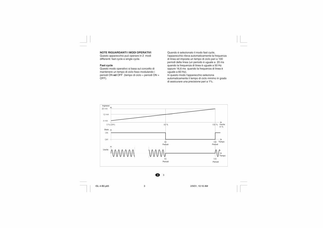
Quando è selezionato il modo fast cycle,l'apparecchio rileva automaticamente la frequenzadi linea ed imposta un tempo di ciclo pari a 100periodi della linea (un periodo è uguale a 20 msquando la frequenza di linea è uguale a 50 Hzoppure 16,6 ms quando la frequenza di linea èuguale a 60 Hz).In questo modo l'apparecchio selezionaautomaticamente il tempo di ciclo minimo in gradodi assicurare una precisione pari a 1%.
NOTE RIGUARDANTI I MODI OPERATIVIQuesto apparecchio può operare in 2 modidifferenti: fast cycle e single cycle.
Fast cycleQuesto modo operativo si basa sul concetto dimantenere un tempo di ciclo fisso modulando iperiodi ON ed OFF (tempo di ciclo = periodi ON +OFF).
Ingresso
Stato
Uscitain %
Tempo
Uscita
Periodi
Periodi
Periodi
Periodi
Tempo
ISL-4-B0.p65 2/9/01, 10:16 AM3

4I
Single cycleQuesto modo operativo riduce drasticamente iltempo di ciclo.Il periodo è preso come tempo base e l'algoritmomodula il tempo di ciclo modificando il periodo ONoppure il periodo OFF.Al 50 % si ottiene il minimo tempo di ciclo che èuguale a 2 periodi (uno ON e uno OFF).
Ingresso
Uscitain %
Stato
Tempo
Uscita
Stato Stato
Uscita Uscita
Tempo Tempo
Tempo Tempo Tempo
da 0 a A1 = 1 periododa 0 a B1 = 4 periodi
da 0 a A2 = 1 periododa 0 a B2 = 2 periodi
da 0 a A3 = 3 periodida 0 a B3 = 4 periodi
NOTA:1 periodo è uguale a:- 20 ms quando la
frequenza di linea èuguale a 50 Hz.
- 16.6 ms quando lafrequenza di linea èuguale a 60 Hz.
ISL-4-B0.p65 2/9/01, 10:16 AM4

5I
NORME GENERALI PER IL FISSAGGIO
1) Gli apparecchi devono essere montativerticalmente o con una inclinazione massimadi 20°.
Fig. 1
Fig. 2
ISL-4-B0.p65 2/9/01, 10:16 AM5

6I
3) Si sconsiglia vivamente di sovrapporre due opiù apparecchi ma, se la cosa si rendesseindispensabile, la distanza tra i due apparecchideve essere superiore a 400 mm.
Fig. 4
2) Gli apparecchi devono essere montati adalmeno 100 mm dal fondo ed almeno 150 mmdal soffitto dell'armadio in cui sono installati.Le stesse distanze vanno rispettate neiconfronti di eventuali canaline o altri elementiche possano limitare la ventilazione delloapparecchio.
Fig. 3
ISL-4-B0.p65 2/9/01, 10:16 AM6

7I
Questo apparecchio può essere montato a pareteoppure su barra Omega DIN.
FISSAGGIO A PARETEPer il fissaggio a parete utilizzare fori (A)
In questo caso si consiglia l'utilizzo di due viti M4serrate con una coppia minima di 1 Nm.
Per le dime di foratura e le dimensioni diingombro, fare riferimento allo specifico disegnomeccanico.I disegni meccanici di tutti i modelli sono riportatinell'appendice A.
FISSAGGIO TRAMITE BARRA OMEGAPer il fissaggio su barra, utilizzare guide OmegaDIN conformi alla specifica EN 50 022 (35 x 7,5mm oppure 35 x 15 mm).
FISSAGGIO
Fig. 5
BarraOmegaDIN
ISL-4-B0.p65 2/9/01, 10:16 AM7

8I
COLLEGAMENTI ELETTRICI
NOTE GENERALI PER ILCOLLEGAMENTO.AVVERTENZE:1) I collegamenti devono essere effettuati dopo che
l'apparecchio è stato montato correttamente.2) Prima di collegare l'apparecchio alla rete,
assicurarsi che la tensione di linea non superi ilvalore nominale indicato sulla targa diidentificazione dell'apparecchio.
3) Prima di collegare l'apparecchio alla rete, assicu-rarsi che la corrente utilizzata dal carico (vedereparagrafo La conversione potenza � correntenominale) sia inferiore alla corrente nominaledell'apparecchio in funzione della temperaturaambiente e del duty cycle (vedere paragrafo An-damento della corrente nominale al variaredella temperatura ambiente e del duty cycle).
4) Prima di eseguire qualsiasi operazione di colle-gamento, assicurarsi che la linea sia statadisconnessa tramite il disgiuntore meccanico.
5) Utilizzare solo conduttori di rame.6) Fare attenzione alla polarità dei terminali del
segnale di ingresso; il terminale 5 è il positivomentre il terminale 6 è il negativo.
7) Se è prevista la connessione al neutro,collegarlo al terminali 2 e 4.
8) L'ingresso di potenza NON è protetto dafusibile; è quindi necessario prevederne unoesterno scelto tra quelli indicati nella Tabella 1.NOTA:Si declina ogni responsabilità per danni a cose opersone derivanti dall'uso di questi apparecchisenza fusibili di protezione o con tipi diversi daquelli indicati nel presente manuale.
RIMOZIONE
Fig. 6
Per le dimensioni di ingombro, fare riferimento allospecifico disegno meccanico.I disegni meccanici di tutti i modelli sono riportatinell' Appendix A.
Cacciavite
ISL-4-B0.p65 2/9/01, 10:16 AM8
9I
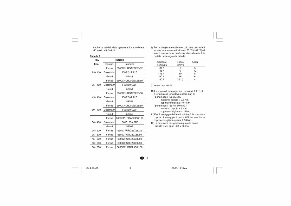
9) Per il collegamento alla rete, utilizzare cavi adattiad una temperatura di almeno 75 °C (167 °F)edaventi una sezione conforme alle indicazioni ri-portate nella seguente tabella:
Corrente � cavo AWGnominale (mm2)
25 A 4 1235 A 6 1045 A 10 860 A 16 680 A 25 (*) 4
(*) senza capocorda
10)La coppia di serraggio per i terminali 1, 2, 3, 4e terminale di terra deve essere pari a:- per i modelli ISL 25 e 35
massima coppia = 0,8 Nm.coppia consigliata = 0,7 Nm
- per i modelli ISL 45, 60 e 80 Amassima coppia = 2 Nm.coppia consigliata = 1,5 Nm
11)Per il serraggio dei terminali 5 e 6, la massimacoppia di serraggio è pari a 0,5 Nm mentre lacoppia consigliata è pari a 0,33 Nm.
12) La circuiteria di ingresso è protetta da unfusibile SMD tipo F, 63 V 63 mA.
Anche la validità della garanzia è subordinataall'uso di detti fusibili.
Tabella 1
ISL Fusibile
tipo Costrut. modello
Ferraz 6600CPURGA22X58/32
25 - 400 Bussmann FWP.32A.22F
Gould 52443
Ferraz 6600CPURGA22X58/50
35 - 400 Bussmann FWP.50A.22F
Gould 53251
Ferraz 6600CPURGA22X58/50
45 - 400 Bussmann FWP.50A.22F
Gould 53251
Ferraz 6600CPURGA22X58/80
60 - 400 Bussmann FWP.80A.22F
Gould 53259
Ferraz 6600CPURGA22X58/100
80 - 400 Bussmann FWP.100A.22F
Gould 53263
25 - 600 Ferraz 6600CPURD22X58/32
35 - 600 Ferraz 6600CPURD22X58/50
45 - 600 Ferraz 6600CPURD22X58/50
60 - 600 Ferraz 6600CPURD22X58/80
80 - 600 Ferraz 6600CPURD22X58/100
ISL-4-B0.p65 2/9/01, 10:16 AM9
10I
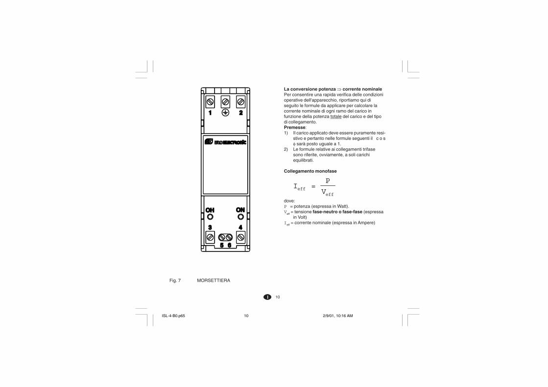
La conversione potenza � corrente nominalePer consentire una rapida verifica delle condizionioperative dell'apparecchio, riportiamo qui diseguito le formule da applicare per calcolare lacorrente nominale di ogni ramo del carico infunzione della potenza totale del carico e del tipodi collegamento.Premesse:1) Il carico applicato deve essere puramente resi-
stivo e pertanto nelle formule seguenti il c o s� sarà posto uguale a 1.
2) Le formule relative ai collegamenti trifasesono riferite, ovviamente, a soli carichiequilibrati.
Collegamento monofase
IP
Veffeff
=
dove:P = potenza (espressa in Watt).Veff = tensione fase-neutro o fase-fase (espressa
in Volt)Ieff = corrente nominale (espressa in Ampere)
Fig. 7 MORSETTIERA
ISL-4-B0.p65 2/9/01, 10:16 AM10
11I
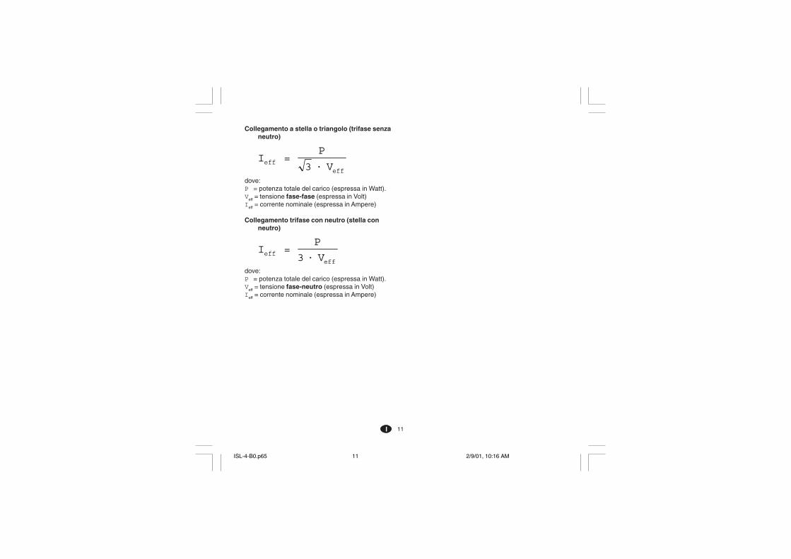
Collegamento a stella o triangolo (trifase senzaneutro)
IP
Veffeff
=·3
dove:P = potenza totale del carico (espressa in Watt).Veff = tensione fase-fase (espressa in Volt)Ieff = corrente nominale (espressa in Ampere)
Collegamento trifase con neutro (stella conneutro)
IP
Veffeff
=·3
dove:P = potenza totale del carico (espressa in Watt).Veff = tensione fase-neutro (espressa in Volt)Ieff = corrente nominale (espressa in Ampere)
ISL-4-B0.p65 2/9/01, 10:16 AM11
12I
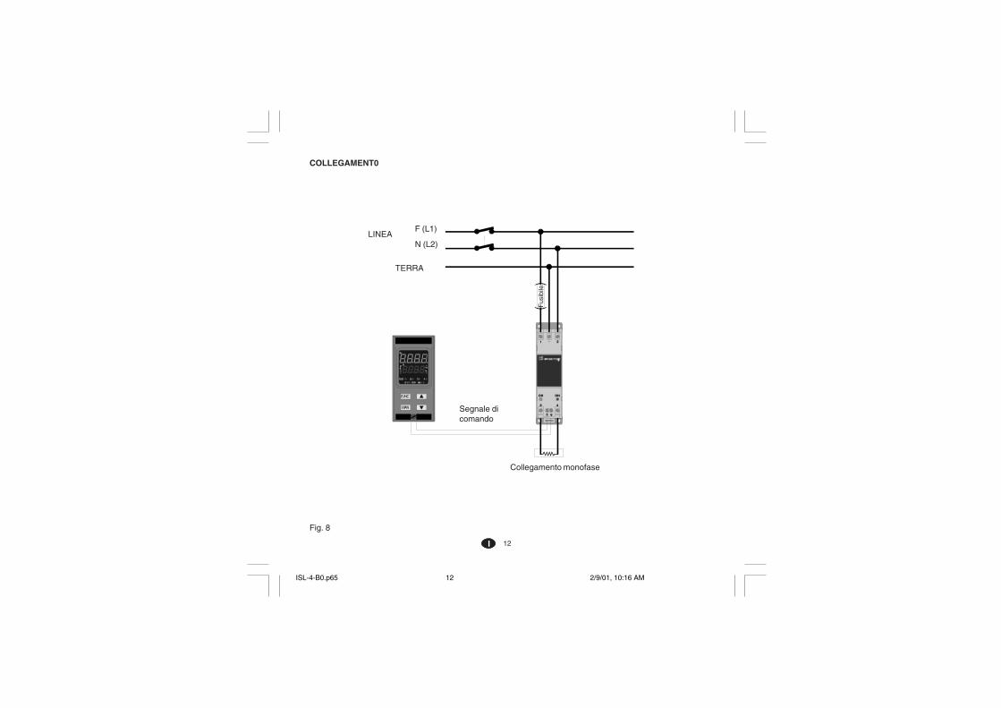
Fig. 8
F (L1)
N (L2)
Fus
ibile
COLLEGAMENT0
TERRA
LINEA
Segnale dicomando
Collegamento monofase
ISL-4-B0.p65 2/9/01, 10:16 AM12

13I
DATI TECNICI COMUNI
Installazione: montaggio a retro-quadro confissaggio a parete o su barra omega DIN.Morsetti: a vite con accesso frontale.Tipo di carico: resistivo.Corrente minima di mantenimento: 50 mA eff.Corrente di dispersione: 10 mA eff.Tensione minima di eccitazione: 40 VCaduta di tensione sui semiconduttori dipotenza: 1,2 V.Tipo di ingresso: lineare 4-20 mAIsolamento:- tra circuiti di potenza e massa: 3000 V eff. per 1
secondo.- tra circuiti di comando e potenza: 7500 Vpk
Resistenza di isolamento:per ISL modelli 400 V è > 1 M� a 500 V c.c.per ISL modelli 600 V è > 2 M� a 500 V c.c.Temperatura di funzionamento: da 0 a 50 °C.Umidità:da 20 % ad 85 % di RH non condensante.Temperatura di immagazzinaggio:da - 20 a + 70 °CProtezione: IP 20.
Protezione termicaQuando la temperatura del radiatore supera lasoglia della protezione termica, un disgiuntoreinterno inibisce il segnale di comando ed abilital'accensione del LED di allarme (OH).Il ripristino del normale funzionamento avvieneautomaticamente quando la temperatura delradiatore scende al di sotto della soglia dellaprotezione termica meno l'isteresi , abilitando ilsegnale di comando e spegnendo il LED diallarme (OH).
MARCATURA CEQuesto apparecchio è conforme alle Direttive89/336/EEC e 93/68/EEC per la CompatibilitàElettromagnetica (Standard Armonizzato diriferimento EN-50081-2 per le Emissioni eEN-50082-2 per le Immunità) ed alle Direttive73/23/EEC e 93/68/EEC per la Bassa Tensione(Norma di riferimento UL508 parte VIII e CEI EN50178).Categoria di installazione: IIGrado di inquinamento: 2
ISL-4-B0.p65 2/9/01, 10:16 AM13

14I
MODELLO
CARATTERISTICHE
Tensione nominale
Corrente nominale (@ 50°C)
Corrente di picco non ripetitiva
I2t per fusibile (10 ms)
Tensione di picco non ripetitiva
�V/�t
PRV
Potenza totale dissipata (I = Inom)
Peso
Amp. - V
25-400
400 V
25 A
280 A
550
1300 V
500 V/�s
1200 V
30 W
630 g
Amp. - V
35-400
400 V
35 A
400 A
860
1300 V
500 V/�s
1200 V
45 W
630 g
Amp. - V
45-400
400 V
45 A
400 A
860
1300 V
500 V/�s
1200 V
55 W
900 g
Amp. - V
60-400
400 V
60 A
1200 A
10180
1300 V
500 V/�s
1200 V
75 W
1100 g
Amp. - V
80-400
400 V
80 A
1200 A
10180
1300 V
500 V/�s
1200 V
100 W
2000 g
CARATTERISTICHE DEI MODELLI ISL
MODELLO
CARATTERISTICHE
Tensione nominale
Corrente nominale (@ 50°C)
Corrente di picco non ripetitiva
I2t per fusibile (10 ms)
Tensione di picco non ripetitiva
�V/�t
PRV
Potenza totale dissipata (I = Inom
)
Peso
Amp. - V
25-600
600 V
25 A
280 A
550
1700 V
1000 V/�s
1600 V
30 W
630 g
Amp. - V
35-600
600 V
35 A
400 A
860
1700 V
1000 V/�s
1600 V
45 W
630 g
Amp. - V
45-600
600 V
45 A
400 A
860
1700 V
1000 V/�s
1600 V
55 W
900 g
Amp. - V
60-600
600 V
60 A
1200 A
10180
1700 V
1000 V/�s
1600 V
75 W
1100 g
Amp. - V
80-600
600 V
80 A
1200 A
10180
1700 V
1000 V/�s
1600 V
100 W
2000 g
ISL-4-B0.p65 2/9/01, 10:16 AM14

15I
MANUTENZIONE
AVVERTENZE1) Prima di eseguire qualsiasi operazione di
manutenzione sull'apparecchio, sul carico o suicollegamenti, assicurarsi che l'apparecchio siastato disconnesso dalla linea tramite ildisgiuntore meccanico.
2) Questi apparecchi hanno una classe diprotezione IP 20 (secondo CEI EN 60529) esono collegati a linee di potenza con tensionipericolose; per queste ragioni:- l'installazione, il collegamento e la manuten-
zione deve essere eseguita da personalequalificato;
- devono essere rispettate tutte le avvertenzeriportate da questo manuale.
3) Non eseguire prove di rigidità dielettrica o diisolamento sui terminali di potenza.Queste tipologie di prove possono danneggiarei semiconduttori di potenza.
4) Durante il normale funzionamento dell'apparec-chio il dissipatore di calore può raggiungere 80°C (176 °F).Prima di effettuare qualsiasi operazione sull'ap-parecchio, assicurarsi che la temperatura deldissipatore sia scesa a livelli accettabili.
MANUTENZIONE ORDINARIA
1) TOGLIERE TENSIONE ALL'APPARECCHIOtramite il disgiuntore meccanico.
2) Facendo uso di un aspiratore o un getto di ariacompressa a bassa pressione (max. 5 kg/cm2)rimuovere eventuali depositi di polvere esporcizia dal dissipatore di calore e dai morsettidi collegamento.
3) Per pulire le parti esterne in plastica, usaresolamente uno straccio pulito ed inumidito con:- alcool etilico (puro o denaturato) [C2H5OH]-alcool isopropilico (puro o denaturato)[(CH3)2CHOH]- Acqua (H2O)
4) Controllare che non vi siano morsetti allentati(vedere NOTE GENERALI PER ILCOLLEGAMENTO ).
5) Prima di rimettere sotto tensione l'apparecchio,assicurarsi che tutte le parti siano perfettamen-te asciutte.
6) Ridare tensione.
ISL-4-B0.p65 2/9/01, 10:16 AM15

16I
Causa probabile
Se ai capi dei terminali 1e 3 non c'è tensione:- il carico è scollegato oppure- il fusibile esterno di potenza è interrotto oppure- non c'è potenza sulla linea.
- Se la tensione ai capi dei terminali 5 e 6 è minore ouguale a 5,1 V, il segnale di comando è minore ouguale a 4 mA.
- Se la tensione ai capi dei terminali 5 e 6 è minore di1,7 V, la polarità del segnale di comando potrebbeessere invertita.
- Se la tensione ai capi dei terminali 5 e 6 è maggioredi 6V, il fusibile interno è interrotto (per la suasostituzione vedere "sostituzione del fusibile" apagina 21).
L'apparecchio pilota una corrente eccessiva inrelazione alla temperatura ambiente.La temperatura ambiente è maggiore dellatemperatura di funzionamento.L'apparecchio è stato montato in una posizione noncorretta.La ventilazione non è sufficente.
Condizione di errore
L'apparecchio èsempre in condizioneOFF e nessun LED èacceso o il LED rossolampeggia.
La protezione termicascatta con troppafrequenza.
Prova
Con un multimetrostandard misurare latensione ai capi deiterminali 1 e 3.
Se la tensione ai capi deiterminali 1 e 3 è ugualealla tensione nominale,misurare la tensione aicapi dei terminali 5 e 6.
RISOLUZIONE DEI PROBLEMI
ISL-4-B0.p65 2/9/01, 10:16 AM16

17I
SOSTITUZIONE DEL FUSIBILE
AVVERTENZE:l) Prima di eseguire qualsiasi operazione di
manutenzione sull'apparecchio, sul carico o suicollegamenti, assicurarsi che l'apparecchio siastato disconnesso dalla linea tramite ildisgiuntore meccanico.
ll) Durante il normale funzionamento dell'apparec-chio il dissipatore di calore può raggiungere80 °C (176 °F).Prima di effettuare qualsiasi operazione sull'ap-parecchio, assicurarsi che la temperatura deldissipatore sia scesa a livelli accettabili.
Come rimuovere il coperchio.a) Sollevare un angolo del coperchio, inserendo la
punta di un cacciavite tra il coperchio el'apparecchio vicino al blocco 1, come indicatonelle seguenti figure.
b) Mantenendo l'angolo sollevato, inserire ilcacciavite vicino al blocco 2 e sollevarequel lato del coperchio.
c) Ripetere le operazioni descritte ai punti a) e b)anche per i blocchi 3 e 4.
d) Sollevare il coperchio.
ISL-4-B0.p65 2/9/01, 10:16 AM17
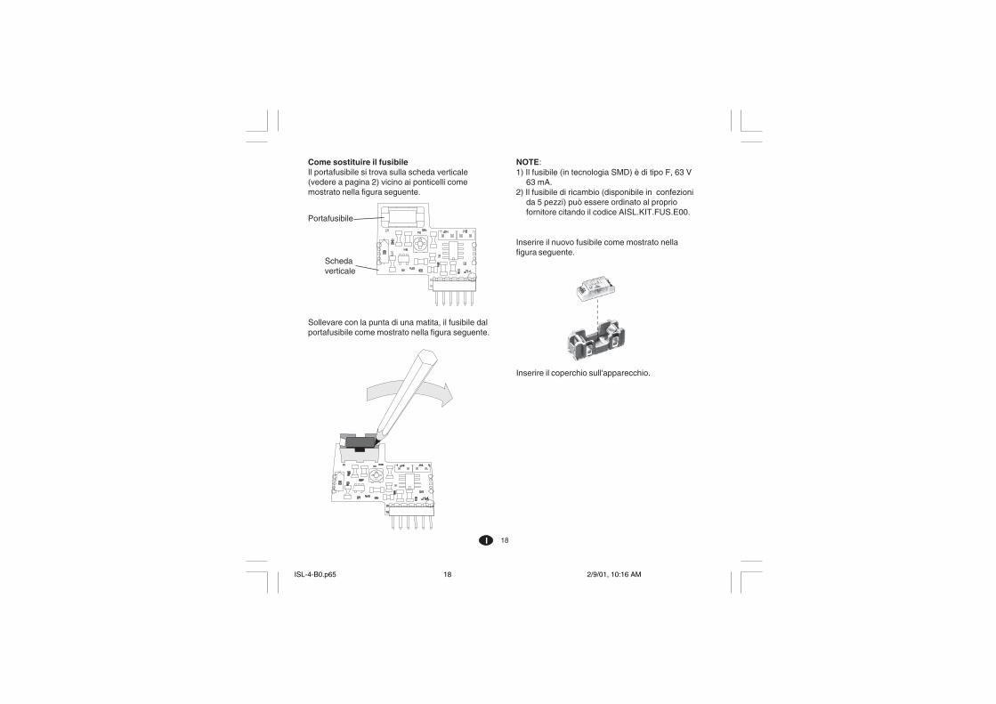
18I
Come sostituire il fusibileIl portafusibile si trova sulla scheda verticale(vedere a pagina 2) vicino ai ponticelli comemostrato nella figura seguente.
Sollevare con la punta di una matita, il fusibile dalportafusibile come mostrato nella figura seguente.
Schedaverticale
NOTE:1) Il fusibile (in tecnologia SMD) è di tipo F, 63 V
63 mA.2) Il fusibile di ricambio (disponibile in confezioni
da 5 pezzi) può essere ordinato al propriofornitore citando il codice AISL.KIT.FUS.E00.
Inserire il nuovo fusibile come mostrato nellafigura seguente.
Inserire il coperchio sull'apparecchio.
Portafusibile
ISL-4-B0.p65 2/9/01, 10:16 AM18
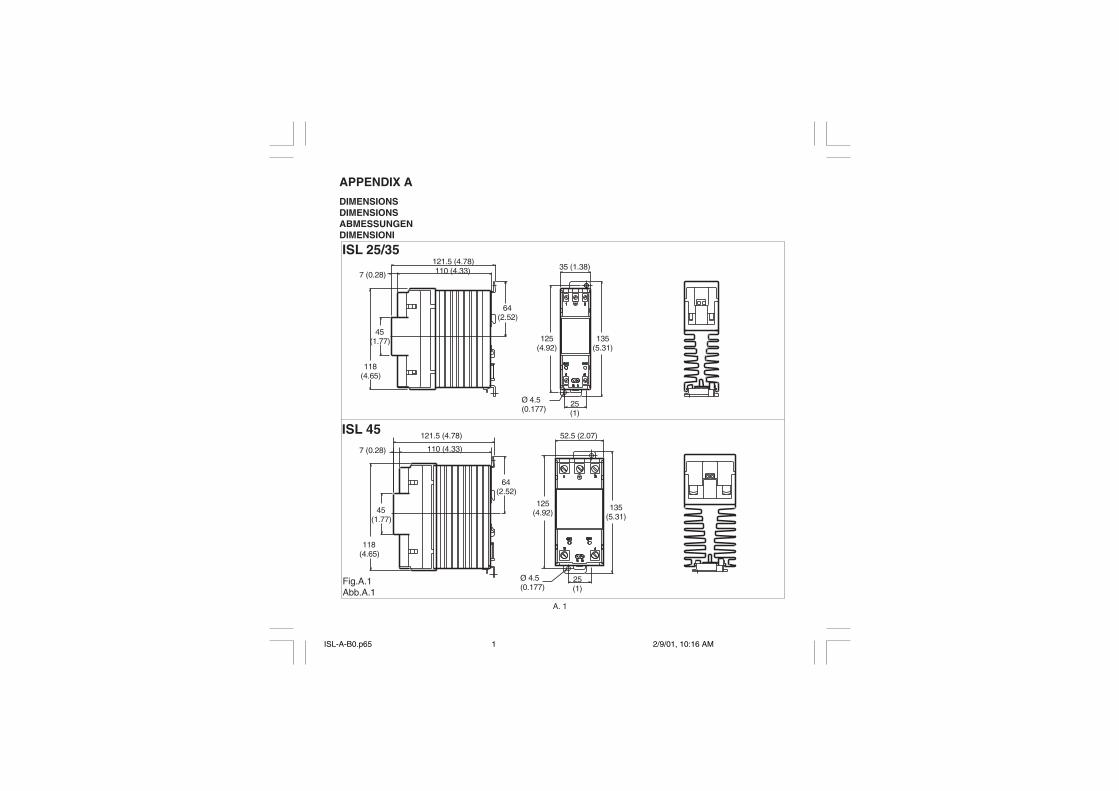
A. 1
DIMENSIONSDIMENSIONSABMESSUNGENDIMENSIONI
APPENDIX A
ISL 25/35
ISL 45
Fig.A.1Abb.A.1
ISL-A-B0.p65 2/9/01, 10:16 AM1
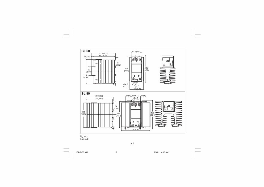
A. 2
Fig. A.2Abb. A.2
ISL 80
ISL 60
ISL-A-B0.p65 2/9/01, 10:16 AM2

A. 3
ISL-A-B0.p65 2/9/01, 10:16 AM3

ISL-A-B0.p65 2/9/01, 10:16 AM4

divisione di EUROTHERM S.r.ldivisione di EUROTHERM S.r.ldivisione di EUROTHERM S.r.ldivisione di EUROTHERM S.r.ldivisione di EUROTHERM S.r.lVia E. Mattei, 2128100 NovaraItalyTel. +39 0321481111Fax +39 0321481112E-mail [email protected]://www.eroelectronic.com
ISL-Z-C0.pmd 04/10/2005, 15.031