is valvesr4:is valves - the valve shop · ... the dew point of the media should be at least ......
TRANSCRIPT

2/2•3/24/2•5/2•5/3
SERIESIS
Entity Groups A-D Groups C-DParameters V max - 30 VDC V max - 34 VDC
I max - 100 mA I max - 125 mACapacitance = 0 Capacitance = 0Inductance = 0 Inductance = 0
4
SPEC
IAL
SERV
ICE
PILO
T
137
% # )
Air and Inert GasIntrinsically Safe Valves
Brass, Aluminum, or Stainless Steel Bodies 1/4" to 1" NPT
ApprovalsFM approved under J.I.3W8A8. AX (3610).CSA certified under File LR-13976.ATEX Ex II1G Ex ia IIC T6 approvedIEC Ga Ex ia IIC T6 approvedMeets applicable CE directives.Refer to Engineering Section for details.
ImportantThese solenoids are intended for use on clean, dry air orinert gas filtered to 50 micrometers or better. To preventfreezing, the dew point of the media should be at least18˚F (-8˚C) below the minimum temperature to which anyportion of the clean air or gas system could be exposed.Instrument air in compliance with ANSI/ISA StandardS7.3-1975 (R1981) exceeds the above requirements andis, therefore, an acceptable medium for these valves.Nominal Wattage is 0.35 @ 24 VDC
Maximum Allowable "Off" State Current to the Valves must be less than 1 mA.Electronically Enhanced "IS" Solenoid:Maximum Capacitor Charge Time — 1 secondMinimum Time between Cycles — 1 secondMinimum Drop Current to Reset Electronic Coil — 2 mANominal Temperature Rise at 24 VDC and 300 Ohms — 2˚C (36˚F)Maximum Recommended Wire Run (#18 Wire) — 1.5 miles from barrier to valveImportant: Minimum series resistance of 200 ohms required in wiring circuit if a safety barrier is not used for non-"IS" system.
Maximum Entity Parameters
Standard Voltage: 24 VDC only (±10%)Minimum Operating Current: 0.028 amps
WBIS: Watertight, Type 3, 3S, 4, 4X, IP-67. Liquid Crystal Polymer (LCP)overmolded with 1/2" NPT conduit connection and screw terminals for simple wiring. The terminal block will accommodate 18 gage (AWG) wire, and grounding screw is located inside the enclosure.ISSC: DIN 43650/ISO 4400, IP-65 Epoxy overmolded with Din Connector supplied, suitable to accept wiring cable diameters of 0.310 to 0.400 inches.
Ordering InformationThe LCP Intrinsically Safe solenoid enclosure is designatedby the prefix “WBIS”. The Epoxy DinConnector is ordered by prefix “ISSC”.Example: WBIS8314A300 Spare Coil P/Ns
ISSC8314A300 WBIS: 274445-001*ISSC: 268976-001*
Solenoid Operators
Features• Intrinsically safe solenoid enclosures to provide corrosion
resistance in harsh environments• Designed solely for installation in intrinsically safe areas,
with properly approved and sized current and voltage-limiting safety barriers
• Acceptable for use in hazardous locations, as classified by the National Electrical Code: Classes I, II, and III, Division 1, including Groups A through G
• Electronically enhanced solenoids have efficient cartridge operators and nonpolarized coils
• Triple redundant diodes prevent electrical pulse from flowing back into the hazardous area
• Mountable in any position
Gasket Cover NBR
Cover Screw 18-8 Stainless Steel
Cover Screw Gasket NBR
Sleeve 430F Stainless Steel
Nameplate Stainless Steel
Burp Cap Assembly PA/CR
Solenoid Construction
Electrical
Valve Parts in Contact with Fluids
Body Aluminum Brass Stainless Steel
Seals and Discs PUR, NBR, FKM, CR, as listed
Sleeve 304L Stainless Steel
Core and Plugnut 430F Stainless Steel
Core Springs 302 Stainless Steel
Pilot Seat Cartridge (Series 8316 & 8344 only) CA
Rider Rings PTFE
Spring Retainer CA
Valve Construction
Series Body Material Temperature Range8551/8553 Aluminum 5˚F to 140˚F (-15˚C to 60˚C)8262
Brass &Stainless Steel -40˚F to 140˚F (-40˚C to 60˚C)
8314831785518551/8553 Stainless Steel8316 Suffix V
Misc.32˚F to 140˚F (0˚C to 60˚C)
All Other -4˚F to 140˚F (-20˚C to 60˚C)
Nominal Ambient Temp. Ranges
IS_ValvesR5

2/2•3/24/2•5/2•5/3SERIESIS 4
SPECIAL SERVICEPILOT
138
Specifications (English units)2/2 VALVES, NORMALLY CLOSED, with NBR Disc
PipeSize(ins.)
OrificeSize(ins.)
Cv FlowFactor
Operating PressureDifferential (psi)
Max. Fluid andAmbient Temp. ˚F
Brass Body Stainless Steel BodyAir-Inert Gas
Min. Max. Catalog NumberConst.Ref. Catalog Number
Const.Ref.
1/4 1/16 .08 0 150 140 WBIS8262A320 1 WBIS8262A386 1A
3/8 5/16 1.5 10 150 140 WBIS8223A323 2 - -
1/2 3/8 3.2 25 150 140 WBIS8223A303 3 WBIS8223A310 3
3/2 VALVES
PipeSize(ins.)
Orifice Size(ins.)
Cv FlowFactor
Operating PressureDifferential (psi)
Max. Fluid andAmbient Temp. ˚F
Brass Body Stainless Steel BodyAir-Inert GasPressure to
CylinderCylinder to
Exhaust Min. Max. Catalog NumberConst.Ref. Catalog Number
Const.Ref.
UNIVERSAL OPERATION (Pressure at any port) with NBR Disc
1/4 1/16 .08 .08 0 150 140 WBIS8314A300 4 WBIS8314A301 4A
NORMALLY CLOSED (Closed when de-energized)
1/4 5/16 1.5 1.5 � 150 140 WBIS8316A301 � 5 WBIS8316A381V � 8
3/8 5/16 1.8 1.8 � 150 140 WBIS8316A302 � 5 WBIS8316A382V � 8
3/8 5/8 4 4 � 150 140 WBIS8316A303 � 6 - -
1/2 5/8 4 4 � 150 140 WBIS8316A304 � 6 WBIS8316A384V � 9
3/4 11/16 5.5 5.5 10 150 140 WBIS8316A374 � 7 - -
1 1 13 13 10 150 140 WBIS8316A334 � 7A - -
UNIVERSAL OPERATION (Normally Closed or Normally Open) “Quick Exhaust” with CR Diaphragm and NBR Disc
1/4 � .08 .73 5 150 140 WBIS8317A307 � 10 WBIS8317A308 � 11
4/2 VALVES, with NBR Disc and Seal
1/4 1/16 .08 .08 10 150 140 WBIS8345A301 �� 12 WBIS8345A381 �� 12
4/2 VALVES, Brass Body with NBR DiscSingle Solenoid
Const.Ref. Dual Solenoid
Const.Ref.
1/4 1/4 .80 1 10 150 140 WBIS8344A370 �� 13 WBIS8344A344 � 16
3/8 3/8 1.4 2.2 10 150 140 WBIS8344A372 �� 14 WBIS8344A380 � 17
1/2 3/8 1.4 2.2 10 150 140 WBIS8344A374 �� 14 WBIS8344A382 � 17
3/4 3/4 5.2 5.6 10 150 140 WBIS8344A376 �� 15 WBIS8344A354 � 18
1 3/4 5.2 5.6 10 150 140 WBIS8344A378 �� 15 WBIS8344A356 � 18
� There are two exhaust flows in the exhaust mode (pilot and main). The pilotexhaust must be connected to the main exhaust when the air or inert gas can not be exhausted to the atmosphere. � For “Quick Exhaust” valves, pressure port is 1/16", exhaust port is 1/4".� IMPORTANT: A minimum operating pressure differential must be maintainedbetween the pressure and exhaust ports. Supply and exhaust piping must be fullarea, unrestricted. ASCO flow controls and other similar components must beinstalled in the cylinder lines only.
� Diaphragm and main disc FKM only (pilot is low-temperature NBR).� Zero minimum when valve selection gasket is in external position and properauxiliary air pressure is applied. See chart on page 146 for auxiliarypressure vs. mainline pressure. Minimum 15 psi Operating Pressure Differentialwhen selection gasket is in the internal position.
IS_ValvesR5
2/2•3/24/2•5/2•5/3
SERIESIS4
SPEC
IAL
SERV
ICE
PILO
T
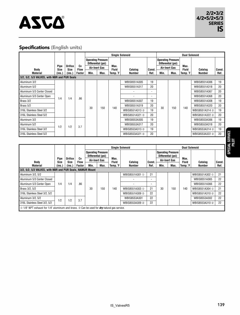
139
BodyMaterial
PipeSize(ins.)
OrificeSize(ins.)
CvFlow
Factor
Single Solenoid Dual Solenoid
Operating PressureDifferential (psi)
Max.Fluid
Temp.˚FCatalogNumber
Const.Ref.
Operating PressureDifferential (psi)
Max.Fluid
Temp.˚F CatalogNumber
Const.Ref.
Air-Inert Gas Air-Inert Gas
Min. Max. Min. Max.3/2, 5/2, 5/3 VALVES, with NBR and PUR Seals
Aluminum 3/2
1/4 1/4 .86
30 150 140
WBIS8551A305 19
30 150 140
WBIS8551A306 19
Aluminum 5/2 WBIS8551A317 20 WBIS8551A318 20
Aluminum 5/3 Center Closed - - WBIS8551A367 20
Aluminum 5/3 Center Open - - WBIS8551A368 20
Brass 3/2 WBIS8551A307 19 WBIS8551A308 19
Brass 5/2 WBIS8551A319 20 WBIS8551A320 20
316L Stainless Steel 3/2 WBIS8551A313 � 19 WBIS8551A314 � 19
316L Stainless Steel 5/2 WBIS8551A321 � 20 WBIS8551A322 � 20
Aluminum 3/2
1/2 1/2 3.7
WBIS8553A305 19 WBIS8553A306 19
Aluminum 5/2 WBIS8553A317 20 WBIS8553A318 20
316L Stainless Steel 3/2 WBIS8553A313 � 19 WBIS8553A314 � 19
316L Stainless Steel 5/2 WBIS8553A321 � 20 WBIS8553A322 � 20
Specifications (English units)
BodyMaterial
PipeSize(ins.)
OrificeSize(ins.)
CvFlow
Factor
Single Solenoid Dual Solenoid
Operating PressureDifferential (psi)
Max.Fluid
Temp.˚FCatalogNumber
Const.Ref.
Operating PressureDifferential (psi)
Max.Fluid
Temp.˚F CatalogNumber
Const.Ref.
Air-Inert Gas Air-Inert Gas
Min. Max. Min. Max.3/2, 5/2, 5/3 VALVES, with NBR and PUR Seals, NAMUR Mount
Aluminum 3/2, 5/2
1/4 1/4 .86
30 150 140
WBIS8551A301 � 21
30 150 140
WBIS8551A302 � 21
Aluminum 5/3 Center Closed - - WBIS8551A365 22
Aluminum 5/3 Center Open - - WBIS8551A366 22
Brass 3/2, 5/2 WBIS8551A303 � 21 WBIS8551A304 � 21
316L Stainless Steel 3/2, 5/2 WBIS8551A309 � 22 WBIS8551A310 � 22
Aluminum 3/2, 5/21/2 1/2 3.7
WBIS8553A301 22 WBIS8553A302 22
316L Stainless Steel 3/2, 5/2 WBIS8553A309 � 22 WBIS8553A310 � 22
� 1/8" NPT exhaust for 1/4" aluminum and brass. � Can be used for dry natural gas service.
IS_ValvesR5
2/2•3/24/2•5/2•5/3SERIESIS 4
SPECIAL SERVICEPILOT
140
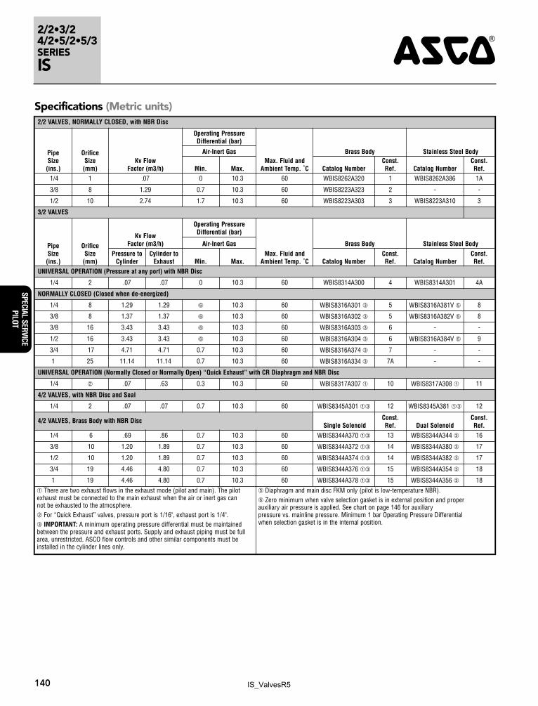
Specifications (Metric units)2/2 VALVES, NORMALLY CLOSED, with NBR Disc
PipeSize(ins.)
OrificeSize(mm)
Kv FlowFactor (m3/h)
Operating PressureDifferential (bar)
Max. Fluid andAmbient Temp. ˚C
Brass Body Stainless Steel BodyAir-Inert Gas
Min. Max. Catalog NumberConst.Ref. Catalog Number
Const.Ref.
1/4 1 .07 0 10.3 60 WBIS8262A320 1 WBIS8262A386 1A
3/8 8 1.29 0.7 10.3 60 WBIS8223A323 2 - -
1/2 10 2.74 1.7 10.3 60 WBIS8223A303 3 WBIS8223A310 3
3/2 VALVES
PipeSize(ins.)
Orifice Size(mm)
Kv FlowFactor (m3/h)
Operating PressureDifferential (bar)
Max. Fluid andAmbient Temp. ˚C
Brass Body Stainless Steel BodyAir-Inert GasPressure to
CylinderCylinder to
Exhaust Min. Max. Catalog NumberConst.Ref. Catalog Number
Const.Ref.
UNIVERSAL OPERATION (Pressure at any port) with NBR Disc
1/4 2 .07 .07 0 10.3 60 WBIS8314A300 4 WBIS8314A301 4A
NORMALLY CLOSED (Closed when de-energized)
1/4 8 1.29 1.29 � 10.3 60 WBIS8316A301 � 5 WBIS8316A381V � 8
3/8 8 1.37 1.37 � 10.3 60 WBIS8316A302 � 5 WBIS8316A382V � 8
3/8 16 3.43 3.43 � 10.3 60 WBIS8316A303 � 6 - -
1/2 16 3.43 3.43 � 10.3 60 WBIS8316A304 � 6 WBIS8316A384V � 9
3/4 17 4.71 4.71 0.7 10.3 60 WBIS8316A374 � 7 - -
1 25 11.14 11.14 0.7 10.3 60 WBIS8316A334 � 7A - -
UNIVERSAL OPERATION (Normally Closed or Normally Open) “Quick Exhaust” with CR Diaphragm and NBR Disc
1/4 � .07 .63 0.3 10.3 60 WBIS8317A307 � 10 WBIS8317A308 � 11
4/2 VALVES, with NBR Disc and Seal
1/4 2 .07 .07 0.7 10.3 60 WBIS8345A301 �� 12 WBIS8345A381 �� 12
4/2 VALVES, Brass Body with NBR DiscSingle Solenoid
Const.Ref. Dual Solenoid
Const.Ref.
1/4 6 .69 .86 0.7 10.3 60 WBIS8344A370 �� 13 WBIS8344A344 � 16
3/8 10 1.20 1.89 0.7 10.3 60 WBIS8344A372 �� 14 WBIS8344A380 � 17
1/2 10 1.20 1.89 0.7 10.3 60 WBIS8344A374 �� 14 WBIS8344A382 � 17
3/4 19 4.46 4.80 0.7 10.3 60 WBIS8344A376 �� 15 WBIS8344A354 � 18
1 19 4.46 4.80 0.7 10.3 60 WBIS8344A378 �� 15 WBIS8344A356 � 18
� There are two exhaust flows in the exhaust mode (pilot and main). The pilotexhaust must be connected to the main exhaust when the air or inert gas can not be exhausted to the atmosphere. � For “Quick Exhaust” valves, pressure port is 1/16", exhaust port is 1/4".� IMPORTANT: A minimum operating pressure differential must be maintainedbetween the pressure and exhaust ports. Supply and exhaust piping must be fullarea, unrestricted. ASCO flow controls and other similar components must beinstalled in the cylinder lines only.
� Diaphragm and main disc FKM only (pilot is low-temperature NBR).� Zero minimum when valve selection gasket is in external position and properauxiliary air pressure is applied. See chart on page 146 for auxiliarypressure vs. mainline pressure. Minimum 1 bar Operating Pressure Differentialwhen selection gasket is in the internal position.
IS_ValvesR5

2/2•3/24/2•5/2•5/3
SERIESIS4
SPEC
IAL
SERV
ICE
PILO
T
141
BodyMaterial
PipeSize(ins.)
OrificeSize(mm)
KvFlow
Factor
Single Solenoid Dual Solenoid
Operating PressureDifferential (bar)
Max.Fluid
Temp.˚CCatalogNumber
Const.Ref.
Operating PressureDifferential (bar)
Max.Fluid
Temp.˚C CatalogNumber
Const.Ref.
Air-Inert Gas Air-Inert Gas
Min. Max. Min. Max.3/2, 5/2, 5/3 VALVES, with NBR and PUR Seals
Aluminum 3/2
1/4 6 .7
2 10 60
WBIS8551A305 19
2 10 60
WBIS8551A306 19
Aluminum 5/2 WBIS8551A317 20 WBIS8551A318 20
Aluminum 5/3 Center Closed - - WBIS8551A367 20
Aluminum 5/3 Center Open - - WBIS8551A368 20
Brass 3/2 WBIS8551A307 19 WBIS8551A308 19
Brass 5/2 WBIS8551A319 20 WBIS8551A320 20
316L Stainless Steel 3/2 WBIS8551A313 � 19 WBIS8551A314 � 19
316L Stainless Steel 5/2 WBIS8551A321 � 20 WBIS8551A322 � 20
Aluminum 3/2
1/2 13 3.7
WBIS8553A305 19 WBIS8553A306 19
Aluminum 5/2 WBIS8553A317 20 WBIS8553A318 20
316L Stainless Steel 3/2 WBIS8553A313 � 19 WBIS8553A314 � 19
316L Stainless Steel 5/2 WBIS8553A321 � 20 WBIS8553A322 � 20
Specifications (Metric units)
BodyMaterial
PipeSize(ins.)
OrificeSize(mm)
KvFlow
Factor
Single Solenoid Dual Solenoid
Operating PressureDifferential (bar)
Max.Fluid
Temp.˚CCatalogNumber
Const.Ref.
Operating PressureDifferential (bar)
Max.Fluid
Temp.˚C CatalogNumber
Const.Ref.
Air-Inert Gas Air-Inert Gas
Min. Max. Min. Max.3/2, 5/2, 5/3 VALVES, with NBR and PUR Seals, NAMUR Mount
Aluminum 3/2, 5/2
1/4 6 .7
2 10 60
WBIS8551A301 � 21
2 10 60
WBIS8551A302 � 21
Aluminum 5/3 Center Closed - - WBIS8551A365 22
Aluminum 5/3 Center Open - - WBIS8551A366 22
Brass 3/2, 5/2 WBIS8551A303 � 21 WBIS8551A304 � 21
316L Stainless Steel 3/2, 5/2 WBIS8551A309 � 22 WBIS8551A310 � 22
Aluminum 3/2, 5/21/2 13 3.7
WBIS8553A301 22 WBIS8553A302 22
316L Stainless Steel 3/2, 5/2 WBIS8553A309 � 22 WBIS8553A310 � 22
� 1/8" NPT exhaust for 1/4" aluminum and brass. � Can be used for dry natural gas service.
IS_ValvesR5
2/2•3/24/2•5/2•5/3SERIESIS 4
SPECIAL SERVICEPILOT
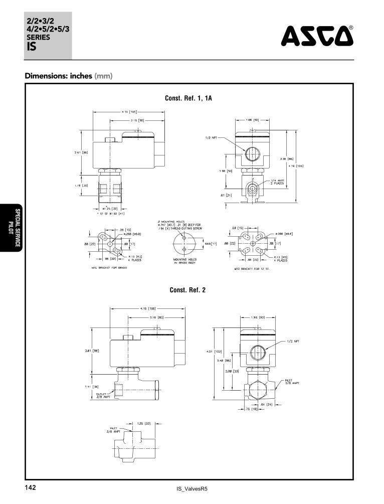
142
Dimensions: inches (mm)
Const. Ref. 1, 1A
Const. Ref. 2
IS_ValvesR5

2/2•3/24/2•5/2•5/3
SERIESIS4
SPEC
IAL
SERV
ICE
PILO
T
143
Const. Ref. 3
Dimensions: inches (mm)
Const. Ref. 4, 4A
IS_ValvesR5
2/2•3/24/2•5/2•5/3SERIESIS 4
SPECIAL SERVICEPILOT
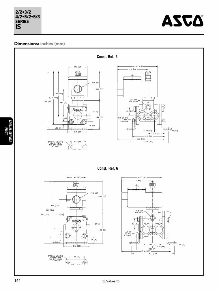
144
Const. Ref. 5
Dimensions: inches (mm)
Const. Ref. 6
IS_ValvesR5
2/2•3/24/2•5/2•5/3
SERIESIS4
SPEC
IAL
SERV
ICE
PILO
T
145
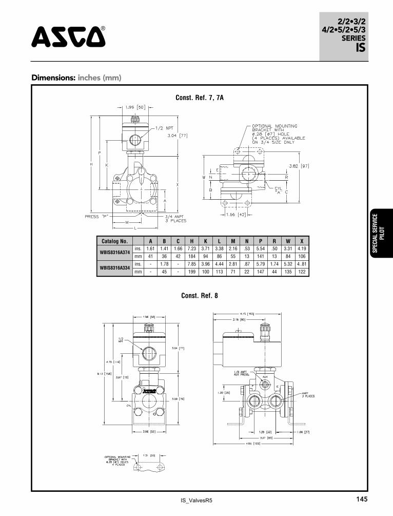
Dimensions: inches (mm)
Const. Ref. 8
Const. Ref. 7, 7A
Catalog No. A B C H K L M N P R W X
WBIS8316A374ins. 1.61 1.41 1.66 7.23 3.71 3.38 2.16 .53 5.54 .50 3.31 4.19
mm 41 36 42 184 94 86 55 13 141 13 84 106
WBIS8316A334ins. - 1.78 - 7.85 3.96 4.44 2.81 .87 5.79 1.74 5.32 4..81
mm - 45 - 199 100 113 71 22 147 44 135 122
IS_ValvesR5
2/2•3/24/2•5/2•5/3SERIESIS 4
SPECIAL SERVICEPILOT
146
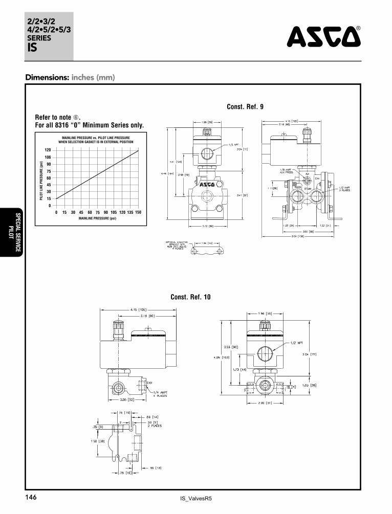
Dimensions: inches (mm)
Const. Ref. 9
Const. Ref. 10
120
15
30
45
60
75
90
106
0
604530150 1351201059075 150
MAINLINE PRESSURE vs. PILOT LINE PRESSUREWHEN SELECTION GASKET IS IN EXTERNAL POSITION
PILO
T LI
NE P
RESS
URE
(psi
)
MAINLINE PRESSURE (psi)
Refer to note �. For all 8316 “0” Minimum Series only.
IS_ValvesR5
2/2•3/24/2•5/2•5/3
SERIESIS4
SPEC
IAL
SERV
ICE
PILO
T
147
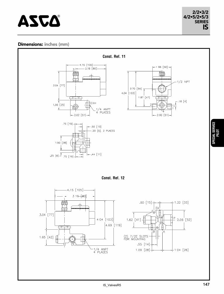
Dimensions: inches (mm)
Const. Ref. 11
Const. Ref. 12
IS_ValvesR5
2/2•3/24/2•5/2•5/3SERIESIS 4
SPECIAL SERVICEPILOT
148
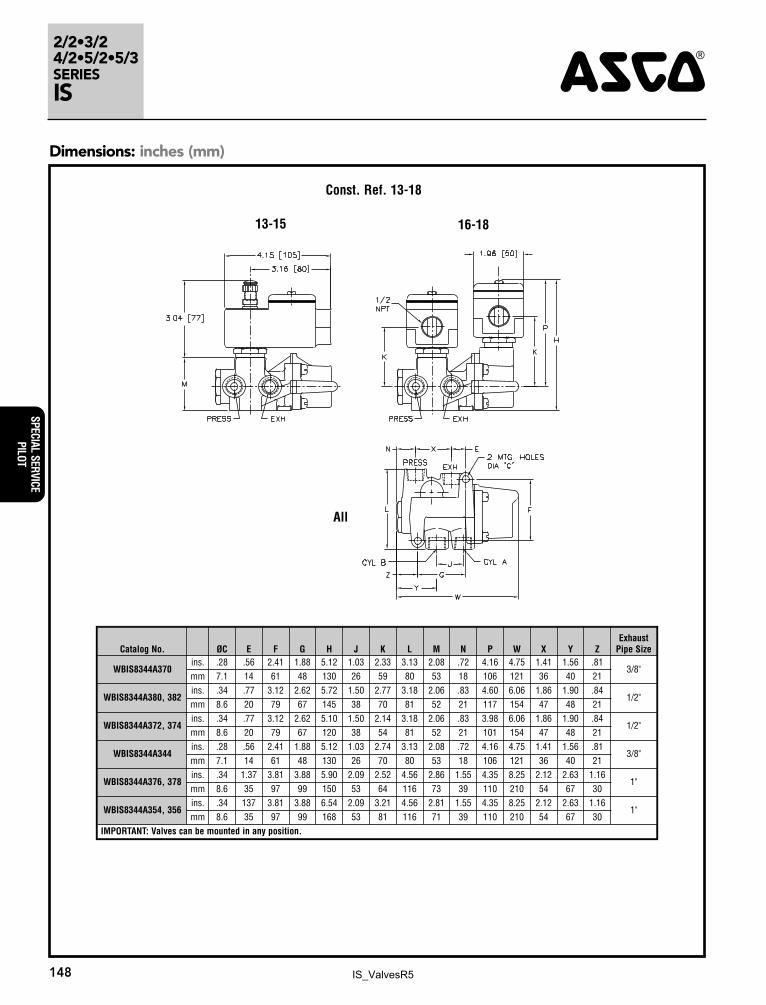
Dimensions: inches (mm)
Const. Ref. 13-18
13-15 16-18
All
Catalog No. ØC E F G H J K L M N P W X Y ZExhaust
Pipe Size
WBIS8344A370ins. .28 .56 2.41 1.88 5.12 1.03 2.33 3.13 2.08 .72 4.16 4.75 1.41 1.56 .81
3/8"mm 7.1 14 61 48 130 26 59 80 53 18 106 121 36 40 21
WBIS8344A380, 382ins. .34 .77 3.12 2.62 5.72 1.50 2.77 3.18 2.06 .83 4.60 6.06 1.86 1.90 .84
1/2"mm 8.6 20 79 67 145 38 70 81 52 21 117 154 47 48 21
WBIS8344A372, 374ins. .34 .77 3.12 2.62 5.10 1.50 2.14 3.18 2.06 .83 3.98 6.06 1.86 1.90 .84
1/2"mm 8.6 20 79 67 120 38 54 81 52 21 101 154 47 48 21
WBIS8344A344ins. .28 .56 2.41 1.88 5.12 1.03 2.74 3.13 2.08 .72 4.16 4.75 1.41 1.56 .81
3/8"mm 7.1 14 61 48 130 26 70 80 53 18 106 121 36 40 21
WBIS8344A376, 378ins. .34 1.37 3.81 3.88 5.90 2.09 2.52 4.56 2.86 1.55 4.35 8.25 2.12 2.63 1.16
1"mm 8.6 35 97 99 150 53 64 116 73 39 110 210 54 67 30
WBIS8344A354, 356ins. .34 137 3.81 3.88 6.54 2.09 3.21 4.56 2.81 1.55 4.35 8.25 2.12 2.63 1.16
1"mm 8.6 35 97 99 168 53 81 116 71 39 110 210 54 67 30
IMPORTANT: Valves can be mounted in any position.
IS_ValvesR5

2/2•3/24/2•5/2•5/3
SERIESIS4
SPEC
IAL
SERV
ICE
PILO
T
149
Dimensions: inches (mm)
Const. Ref. 20
H2
H1
L1
L2
3 1
1
W
1.96 (48)
4.15 (105)
3.04 (77)
1/2 NPT
3.16 (80)
1/8 NPT AUX. PRESSURE PORT
Const. Ref. 19
Optional Manual OperatorsAdd Suffix Description
MO1
20
Push and turn to lock with flathead screwdriver slot
MI1
20
Momentary push in with flathead screwdriver slot
MH
1
20Momentary push in by hand
MS
1
20Push and turn to lock by hand
Series 8551 8553NPT 1/4 1/2L1 � 5.12 (132) 6.00 (153)L2 � 6.73 (171) 7.80 (198)H2 4.38 (111) 4.77 (121)H1 1.10 (28) 1.58 (40)W 1.77 (45) 2.85 (72)
� Manual override option MH adds .250" (6.4), MS option adds .468" (11.9) to each solenoid endcap.
Optional Manual OperatorsAdd Suffix Description
MO1
20
Push and turn to lock with flathead screwdriver slot
MI1
20
Momentary push in with flathead screwdriver slot
MH
1
20Momentary push in by hand
MS
1
20Push and turn to lock by hand
� Manual override option MH adds .250" (6.4), MS option adds .468" (11.9) to each solenoid endcap.
Series 8551 8553NPT 1/4 1/2L1 � 5.63 (144) 7.06 (180)L2 � 7.20 (183) 8.86 (225)H2 4.38 (111) 4.77 (121)H1 1.10 (28) 1.58 (40)W 1.77 (45) 2.85 (72)
H2
H1
L1
L2
5 1 3
W
1/2 NPT
1.96 (48)
3.04 (77)
4.15 (105)
3.16 (80)
1/8 NPT AUX. PRESSURE PORT
IS_ValvesR5
2/2•3/24/2•5/2•5/3SERIESIS
Dimensions: inches (mm)
SPECIAL SERVICEPILOT
4
150
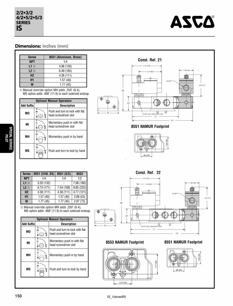
Const. Ref. 22
H2
H1
L1
L2
3 1
1
W
1.96 (48)
4.15 (105)
3.04 (77)
1/2 NPT
3.16 (80)
1/8 NPT AUX. PRESSURE PORT
Const. Ref. 21
8553 NAMUR Footprint 8551 NAMUR Footprint
8551 NAMUR Footprint
42
.95 (24)
1.26
(32
)
42
1.57 (40)
1.77
(45
)
42
.95 (24)
1.26
(32
)
H2
H1
L1
L2
5 1 3
W
1/2 NPT
1.96 (48)
3.04 (77)
4.15 (105)
3.16 (80)
1/8 NPT AUX. PRESSURE PORT
Optional Manual OperatorsAdd Suffix Description
MO1
20
Push and turn to lock with flathead screwdriver slot
MI1
20
Momentary push in with flathead screwdriver slot
MH
1
20Momentary push in by hand
MS
1
20Push and turn to lock by hand
Series 8551 (Aluminum, Brass)NPT 1/4L1 � 4.96 (126)L2 � 6.49 (165)H2 4.38 (111)H1 1.57 (40)W 1.77 (45)
� Manual override option MH adds .250" (6.4), MS option adds .468" (11.9) to each solenoid endcap.
Optional Manual OperatorsAdd Suffix Description
MO1
20
Push and turn to lock with flathead screwdriver slot
MI1
20
Momentary push in with flathead screwdriver slot
MH
1
20Momentary push in by hand
MS
1
20Push and turn to lock by hand
Series 8551 (316L SS) 8551 (5/3) 8553NPT 1/4 1/4 1/2L1 � 5.20 (132) - 7.08 (180)L2 � 6.73 (171) 7.44 (189) 8.85 (225)H2 4.38 (111) 4.38 (111) 4.77 (121)H1 1.57 (40) 1.57 (40) 2.08 (53)W 1.77 (45) 1.77 (45) 2.87 (73)
� Manual override option MH adds .250" (6.4), MS option adds .468" (11.9) to each solenoid endcap.
IS_ValvesR5