is-3007_1 - laying of asbestos cement sheets
TRANSCRIPT

7232019 Is-3007_1 - Laying of Asbestos Cement Sheets
httpslidepdfcomreaderfullis-30071-laying-of-asbestos-cement-sheets 124
IS 3007 (Part 1) 1999
Indian Standard
LAYING OF ASBESTOS CEMENT SHEETS -
CODE OF PRACTICEPART 1CORRUGATED SHEETS
(First Revision )
ICS 9110040
8 BI S 1999
BUREAU OF INDIAN STANDARDS
MANAK BHAVAN 9 BAHADUR SHAH ZAFARMARG
NEW DELHI 110002
7232019 Is-3007_1 - Laying of Asbestos Cement Sheets
httpslidepdfcomreaderfullis-30071-laying-of-asbestos-cement-sheets 224
Cement Matrix Products Sectional Committee CED 53
FOREWORD
This Indian Standard ( First Revision ) was adopted by the Bureau of Indian Standards alter the draft finalized by
the Cement Matrix Products Sectional Committee had been approved by the Civil Engineering Division Council
Corrugated asbestos cement sheets are commonly used in this country for providing structural surfaces exposed
to weather such as roofs of industrial institutional commercial and residential buildings Covering of asbestos
cement corrugated sheetshave many advantages such as lightness ease and quickness of construction and durability
but to realise full advantages from this type of covering proper selection of various accessories and good workmanship
are essential This code is intended to give guidance in the selection of materials and laying of asbestos cement
corrugated sheets for obtaining satisfactory performance
This standard has been published in two parts Part 1 covers laying of corrugated sheets and Part 2 covers laying
of semi-corrugated sheets conforming to IS 459 1992 lsquoSpecification for unreinforced corrugated and semi-corrugated
asbestos cement sheetsrsquo
This standard was originally published in 1964 This first revision has been done in the light of experience gained
in its use over the years In this revised version brought out in SI units important changes have been made in the
clauses on design consideration spacing of purlin storage and handling at site safety precautions besides adding
new clauses covering expansion joints shade protection and recommended work practice
In the formulation of this standard due weightage has been given to the need for international co-ordination among
standards prevailing in different parts of the world Guidance has been taken from
IS0 8108 1986 Directives for fixing asbestos cement corrugated asymmetrical section sheets and fittings for
roofing
BS 5247( Part 14) 1975 Code of practice for sheet roof and wall coverirgs
IS 11769 ( Part 1) 1987 Guidelines for safe use of products containing asbestos Part 1 Asbestos cement products
7232019 Is-3007_1 - Laying of Asbestos Cement Sheets
httpslidepdfcomreaderfullis-30071-laying-of-asbestos-cement-sheets 324
IS 3007 (Partl) 1999
Indian Standard
LAYING OF ASBESTOS CEMENT SHEETS -
CODE OF PRACTICE
PART 1 CORRUGATED SHEETS
(First Revision )
1 SCOPE
This standard ( Part 1) lays down the method of laying
and fixing corrugated asbestos cement sheets used
as covering for roofs and walls
2 REFERENCES
The Indian Standards listed in Annex A contain
provisions which through reference in this text
constitute provisions of this standard At the time
of publication the editions indicated were valid All
standards are subject to revision and parties to
agreements based on this standard are encouraged
to investigate the possibility of applying the most recent
editions of the standards indicated in Annex A
3 TERMINOLOGY
For the purpose of this standard the folowing
definitions shall apply
31 Abutment
Sloping intersection of a roof surface with a part of
the structure which rises above it
32 Accessories
Purpose made fittings such as ridge cappings north
light curves ridge finials apron flashing pieces eaves
filler pieces bargeboards expansion pieces ventilators
skylights and similar fittings with which the roof is
furnished
33 Apron Flashing Piece
Flashing the lower edge of which is lapped over the
roof covering
34 Asbestos Building Board
Asbestos cement flat panel used for interior work that
is ceiling partition etc with a good workability and
flexibility
35 Asbestos Cement
A material composed of asbestos fibre and Portland
cement
36 Eaves
The lower edge of an inclined roof
3 7 Eaves Filler or Closure Piece
Asbestos cement accessory used to fill or close the
corrugation spaces under the roof sheeting at the
eaves
38 Finial or Ridge End
Asbestos cement accessory to form waterproof
covering at the end of a ridge
39 Gable
Part of a wall above the general eaves level at the end
of a ridged or partially hipped roof
310 Gutter
Any form of roof water channel
311 Hip
Raking salient angle formed by the intersection of two
inclined roof surfaces
312 Hip-Ridge or Capping
Asbestos cement accessory used to form waterproof
covering to a hip
313 Mitre
Cutting the joining surfaces of two sheets at an angle
314 Pitch
Angle of inclination with the horizontal of the rafters
or substructure surface on which the roof coveringis laid
315 Ridge
Line of intersection of two inclined roof surfaces at
the apex of a roof
316 Ridge Capping
Asbestos cement accessory to form a waterproof
covering to a ridge
317 Valley
Re-entrant racking angle formed by the intersection
of two inclined roof surfaces
1
7232019 Is-3007_1 - Laying of Asbestos Cement Sheets
httpslidepdfcomreaderfullis-30071-laying-of-asbestos-cement-sheets 424
IS 3007 Part 1) 1999
318 Verge
Free edge of a roof surface finishing at a gable
4 NECESSARY INFOBMATION
41 For the efficient planning and execution of the
work detailed information with regard to the following
6 DESIGN CONSIDERATIONS
61 Durability
Asbestos cement corrugated sheets which are
untreated on the exposed face will be affected in the
following ways when exposed to the atmosphere
is necessarya) Roof area to be covered
b) Details of sub-structure of roof
c) Pitch of the roof and
d) Location and size of openings and details of
roofing actiessories to be fixed
42 All the information stated in 41 shall be made
available by the appropriate authority responsible for
the construction of the whole building to those who
are entrusted with the work of laying roof sheetingbefore the work is started Necessary drawings and
instructions for preparatory work shall also be given
where required
43 Arrangements shall also be made for the proper
exchange of information between those engaged in
laying the roof covering and all other whose work will
be affected
5 MATERIAL
51 Asbestos Cement Sheets
Asbestos cement corrugated sheets shall conform to
IS 459
a) Age will bring about a reduction in resistanceto impact but transverse strength of sheets
will improve
b) Slight expansion shrinkage or curling may
cause cracking if the sheets are fixed too
rigidly to the supporting structure
Asbestos cement sheeting may be regarded as having
a normal life of at least 40 years Durability depends
mainly on the degree of acid pollution of the internal
or external atmospheres
Atmospheric pollution is not normally sufficientlyconcentrated to be harmful In order to secure a sound
and permanent roof with maximum economy the
requirementsspeciiiedin611to617shallbefollowed
611 Roof Plan
The roof plan shall be as simple as possible Formation
of hips and valleys should be avoided as far as possible
Isolated projections above roof should be avoided
at the design stage itself as it is difficult to make the
junctions between such projections and the roof
sheeting weather proof
612 Pitch of the Roof
511 $hallow Corrugated The pitch of roofs shall wherever possible be
Asbestos cement sheets shall conform to IS 13008
512 Asbestos cement roofing fittings shall conform
to IS 1626 (Part 3 )
513 Asbestos cement gutters and gutter fittings shall
conform to IS 1626 (Part 2 )
preferably not less than 18rdquo should it however be
found desirable to adopt roofs with a pitch less than
18rdquo the values prescribed in 616 for the end laps
between adjacent sheets shall be correspondingly
increased andor the joints suitably sealed in accordance
with the manufacturerrsquos recommendations or the
instructions of the engineer-in-charge
52 Asbestos Cement Building Boards 613 Purlins
Asbestos cement building boards where required
shall conform to IS 2098All purlins shall be in one plane and shall be properly
anchored to the supporting structure Special care
521 Asbestos cement flat sheets shall conform to shall be taken that the sheets do not deflect at the
IS 2096 intermediate purlins in an attempt to make the sheets
522 Silica asbestos cement flat sheets shall conformbear on such purlins The contact surface between
to1s 13000the sheets and their supports shall be such that
puncturing can be avoided
53 Fixing Accessories6131 Spacing ofpurlins
Fixing accessories such as J-bolts L-bolts roof
washers etc shall conform to IS 730 The spacing of purlins shall be arranged to suit thestandard lengths of sheets but shall not exceed the
531 Coach screws shall conform to IS 1120 following
2
7232019 Is-3007_1 - Laying of Asbestos Cement Sheets
httpslidepdfcomreaderfullis-30071-laying-of-asbestos-cement-sheets 524
Thickness of Sheet Distance Between
Purlin Centres
For roof For side
covering cladding
mm m m
4 ( Shallow corrugations ) 08 135
6 ( Medium corrugations ) 14 170
6132 Ridge purlins shall be fixed 75 to 115 mm
from the apex of the roof that is from the bolt point
614 Additional trimmers or bridging shall be used
between purlins at all points where considerable roof
traffic is likely to occur for example adjoining valley
or box gutters below glazing and around chimneys
ventilators or other uptakes This should be done on
new roofs and when recovering or repairing existing
roofs Similarly when a course of sheets of smallerlength necessitating closer purlin spacing is required
to make up a roof slope it is desirable to arrange the
closer purlin spacing at eaves rather than at ridges
as this will bring additonal support where it is most
required
615 Hip and valley runners should be provided
fixed flush with the top face of purlins and spanning
between them to give adequate support to the raking
cut edges of roof sheets at hips andrsquovalleys The runners
should run parallel to the edge of the sheeting and
placed so as to permit the fixing of the sheets and hip
covering accessories
616 Laps
All the overlaps should be placed on the supports
The sheets shall be laid with a side lap of half
corrugation (see Fig 1) For normal roof pitch (that
is inclinations greater than or equal to ltlsquo) the end
laps (see Fig 2) in sheets shall not be less than
150 mm For low roof pitches (that is inclinations
less than 18rsquo) or for normal pitched roof in exposed
position the end laps shall be increased and it is
IS 3003 (Part 1) 1999
desirable to consult the manufacturers in such cases
The side laps shall as far as possible be sheltered from
the prevailing wind direction The free overhang at
eaves measured as the length of sheet from its lower
edge to the centre of bolt holes shall not be more than
300 mm for 6 mm thick sheets and 150 mm for 4 mm
thick (shallow corrugations) sheets Wherever four
comers of sheets overlap two of them shall be mitredin the manner described in 935 in order to secure a
perfect frt
617 In order to avoid undue width of flashing the
sheets should finish at abutments as far as possible
with an upturned edge
62 Spacing of Supports and Strength of Sheeting
621 General
The purlins and rails shouldbe spaced to suit the sheet
profiles and the standard length available whereverpossible If ventilators roof lights are to be used on
the roof slope the supporting strncture should provide
the necessary support without restricting or
obstructing the flow of air
622 ImposedRoof Loads
6221 Sloping roofs
On roofs with a slope of 10 to 30deg andwith no access
provided to the roof (other than that necessary for
cleaning and repair) allowance should be kept for an
imposed load exerting a force of 075 kNmrsquo measuredon plan or a vertical load exerting a force of 09 kN
concentrated on a square with a 300 mm side measured
on slope
6222 Flat roofs
On roofs up to and including 10rdquo where access (in
addition to that necessary for cleaning and repair) is
provided to the roof allowance should be made for
an imposed load including snow exerting a force of
15 kNm2 measured on plan or a load exerting a force
of 18 kN concentrated on a square with 300 mm side
fJ-TYPE HOOK BOLT
GI FLAT WASHER
BITUMINOUS FELT WASHER
WIND DIRECTION
7232019 Is-3007_1 - Laying of Asbestos Cement Sheets
httpslidepdfcomreaderfullis-30071-laying-of-asbestos-cement-sheets 624
IS 3007 (Part 1) 1999
J-TYPE HOOK
BOLT -44
SHEET
MS ANGLE WRLlN-- amp+==rdquo
FIG2 DETAILOFEND LAP
measured on slope On roofs up to and including 10rsquo
where no access is provided (other than that necessary
for cleaning and repair) allowance should be made
for an imposed load including snow exerting a force
of 075 kNmrsquo measured on plan or a load exerting
force of 09 kN concentrated on a square with a
300 mm side measured on slope
63 Wind Loads
Corrugated sheets should be designed to resist the
combined effects as well as the separate effects of
imposed loads and the wind loads For details of wind
pressures and suction IS 875 ( Part 3 ) may be referred
64 Expansion Joints
When the length of asbestos cement sheeting exceeds
45 m expansion joints should be provided in the roof
covering and vertical cladding these should be
designed in relation to another One expansion joint
is to be provided in continuous run of sheeting up to
75 m in length and one for each additional 30 m It is
essential that expansion joints in asbestos cement be
designed to coincide with any such joints provided
in the structure The joints in both the roof and wall
covering should be designed to suit the type of sheeting
used in conjunction with specially made joint
accessories which are available for standard types
of sheets
7 STORAGE AND HANDLING AT SITE
71 All asbestos cement units shall be protected from
damage while stored on site They shall be carefully
stacked in sheltered positions as near as possible to
the parts of the building on which they will be fixed
than one metre on firm and level ground with timber
or other packing beneath them If of necessity they
are to be placed in an exposed position they shall be
protected from damage by the winds While stacking
sheets all uplap should be on one side and all down
lap should be on the other side but uplap and downlap
should not be mixed
73 Asbestos cement materials of same variety andsize shall be stacked together Damaged material shall
not be stacked with sound materials All damaged
materials shall be salvaged as early as possible
74 All sheets and fittings including gutters and
downpipes brackets fixing bolts or screws and any
accessories required for a particular roof area shall
be on the site or available before the work is commenced
75 The sheets shall be raised to the roof using adequate
manual or mechanical means in particular avoiding
impacts76 During receiving and storing of asbestos cement
corrugated sheets and fittings recommendations
given in 4 of IS 11769 ( Part 1) shall be followed to
ensure minimum release of airborne dust and thus
minimum exposure of workers to such airborne
asbestos dust
77 Shade Protection
If asbestos cement sheets are stored and stacked in
the open for long periods without protection from the
sun the sunrsquos rays may make one side of a stack ofsheets very hot leaving the other side at shade
temperature and thereby setting up stresses which
may result in cracking Hence it may be necessary to
protect stacks of sheets from the sun using methods
7232019 Is-3007_1 - Laying of Asbestos Cement Sheets
httpslidepdfcomreaderfullis-30071-laying-of-asbestos-cement-sheets 724
771 Method 1
Three-metre sheets are laid transversely on a stack
of sheets This method also provides shade to the
side of the sheets (see Fig 3 )
772 Method 2
Same as in Method 1 and Fig 3 with addition of one15 m sheet laid at each end of the stack to provide
requisite shade (see Fig 4)
773 Method 3
Lay 15 m sheets around to lean against the stack as
indicated in Fig 5 This method provides shade
from all directions It is recommended that sheets
placed in shade protection as demonstrated in the
-3m AC SHEETSON TOP- 3 Nos
- STACK OF 3mAC SHEETS
3m AC SE$S ON TOP
7STACK OF 3m AC SHEETS7
ELEVATION
FIG 3 SHADE PROTECTION ETHOD
I TACK
IS 3007 (Part 1) 1999
foregoing illustrations should be prevented from being
blown away by suitable means
8 SAFETY PRECAUTIONS
81 No person other than workmen employed shall
be permitted access to any area over which the sheeting
is being laid If however it is not possible to keepthis area clear protective measures shall be taken during
the progress of the work
811 Notices warning workmen not to step on to the
roof sheeting should be provided in conspicuous
positions on the walkways and at all usual points of
access to the roof
82 Cat ladders or roof boards shall invariably be used
by men working on the roofs for safety which will
LlSm SHEETS
15m SHEETS LEANINGAGAINST THE STACK OFAC SHEETS
7
ELEVATION WITH FRONT
LEANING SHEETS REMOVED
7232019 Is-3007_1 - Laying of Asbestos Cement Sheets
httpslidepdfcomreaderfullis-30071-laying-of-asbestos-cement-sheets 824
IS 3007 (Part 1) 1999
3m AC SHEETS
3 Nos
FIG 5 SHADEPROTECTION ETHOD
incidentally avoid damage to the roofing materials also
Roof boards shall not be less than 375 mm wide andshall be well constructed to avoid tilting of materials
The battens or crosspieces of roof board shall not
project beyond the edges of the board and shall be
properly secured to the board
83 During laying it is essential that the workmen
walk on and work from planks or ladders avoiding the
need to step or crawl directly on the sheets Safety
posters warning workmen not to step on the roofing
sheeting should be prominently displayed
84 Supervisors should ensure the proper distribution
to and use by the operatives of such safety devices
such as access ladders and helmets
85 It is essential that operatives do not use shoes
with slippery soles when laying or fixing roofing sheets
86 Before leaving the site all sheets on the roof shall
be fixed and no loose tools fasteners or sheets which
are not fixed shall be left on the roof
87 Sheeting operations should be suspended at times
of high winds
88 Asbestos cement products normally contain onlysmall percentage of asbestos and are safe to handle
Where a limited amount of cutting such as mitring is
done in the open air the dust level is generally low
but if any doubt exists IS 11769 ( Part 1 ) may be
referred to or clarification should be sought from the
manufacturer
9 LAYING AND FIXING OF SHEETS
91 Sawing and Drilling
Sheets shall be cut as necessary with a wood saw
Holes in the sheets shall be drilled they shall on noaccount be punched The latter method not only splays
out the aperture thus weakening the material at
vulnerable points but is also likely to commence a
fracture of the sheet which will ultimately open out
in weathering The holes for fixing shall be 2 mm larger
than the diameter of the fixing bolts and shall alwaysbe drilled through the crown of the corrugation and
not on the valleys
911 Holes for fixing the sheeting shall be drilled in
the centre of the end lap of sheets to suit the purlins
that is on the centre line of the purlins if these are of
timber and square head coach screws are used or as
close as possible to the back of the purlins if J- or
L-bolts are used with steel angles or precast concrete
or timber purlins It is recommended therefore to
drill the holes on the roof with the sheeting laid in
the correct position Drilling of holes must be doneat least 75 mm away from edge of sheet
912 Recommended Work Practices in Sawing and
Drilling
In cutting of sheets different tools as mentioned in
Table 1 may be used with a view to maintain the dust
emission at the lowest practicable level while taking
into account working efficiency and quality of work
but if any doubt exists clarification should be sought
from the manufacturer
92 Fixing Accessories
921 The satisfactory service of the roofing depends
to a great extent upon the efficiency of fixing
accessories It is therefore important that particular
attention is paid to the proper selection and use of
fixing accessories The fixing accessories shall conform
to the requirements of IS 730
922 Galvanized iron l-type hook bolts or cranked
hook bolts and nuts bearing on galvanized iron washers
and bitumen washers shall be used for fixing sheets
on angle iron purlins
923 Galvanized iron L-type hook bolts and nuts
bearing on galvanized iron washers and bitumen
washers shall be used for fixing sheets on RS joists
precast concrete or timber purlins
7232019 Is-3007_1 - Laying of Asbestos Cement Sheets
httpslidepdfcomreaderfullis-30071-laying-of-asbestos-cement-sheets 924
IS 3007 (Part 1) 1999
Table 1 Working Processes and Recommended Tools
Corrugated Sheets and Fittings
( Clause 912 )
Working Process Recommended Tools
Mitring Hand saw scriber lsquo)jig saw nibbler hand guided band saw low speed circular saw
Cross cutting Hand saw lsquo)jig saw nibbler low speed circular saw
Longitudinal cutting Scriber jig saw nibbler hand saw low speed circular saw
Cut outs lsquo)Jig saw hand saw low speed circular saw
Drilling Hand or power operated drill
lsquo) Other mechanically operated saws may be used with special precautions Circular high speed saws are not recommended
924 Galvanized iron coach screws bearing on
galvanized iron washers and bitumen washers shallbe used for fixing sheets on timber purlins
925 Galvanized iron roof bolts and nuts bearing on
galvanized iron flat washers and bitumen washers shall
beusedforfixingofthesheetstilikeridgedcappings
comer pieces ventilators northlight curves etc
926 Where sheets are laid on tubular purlins the fixing
bolt should be designed to encompass at least half
the tube periphery and precautions should be taken
to prevent its rotation Sections other than angles and
tubes may require an adapted form of hook bolt9261 Direct fixing of sheets to drilled metal frame
work or by stud welding it undesirable as it tends to
restrain movement of sheets
927 It is essential that the bolt holes are made
watertight by the use of bituminous felt washers in
conjunction with suitable galvanized iron washers
These form essential accessories to good fixing work
Fixing bolts and screws shall be 8 mm or more in
diameter and nuts of the hook crank bolts (or heads
of coach screws) shall bear on galvanized iron washers
(flat curved or diamond pattern) which in turn shall
be embedded on bituminous felt washers (round ordiamond pattern) corresponding to the shape of
galvanized iron washers The screws or nuts shall
be tightened sufficiently only to seat the bitumen washer
over the corrugations so that natural movement in
the sub-structure of the roof may not damage the
sheeting
9271 The length of the J-bolt or crank bolt shall be
75 mm longer than the depth of the purlin for single
sheet fixing and 90 mm longer than the depth of the
purlin where two sheets overlap or where ridges or
other accessories are to be fixed with the sheet Theminimum length of square head coach screw for timber
purlins shall be 110 mm The number and length of
bolts and the number of bitumen and galvanized iron
washers for fixing asbestos cement corrugated sheets
shall be as given in Table 2
928 The galvanized iron flat washer shall generally
be 25 mm in diameter and 16 mm thick with hole to
suit the required size of fixing accessory and the bitumen
washer shall be 35 mm in diameter and 15 mm thick
with hole to suit the required size of fixing accessory
Table 2 Number and Length of Bolts and Number of Bituminous Felt and Galvanized Iron Washers
( Clause 9271)
Sl
No
Situation No of Bolts and
Bitumnous Washers
and GI Washers
Length of
Bolt
i) At horizontal (end) laps of sheets At eaves Twice the number of sheets in one Depth of purlin + 90 mm
when filler pieces are used At ridge when horizontal course
corrugated sheets and ridge pieces are
secured by the same bolt
ii) At eaves when filler pieces are not used At Twice the number of sheets in one Depth of purlin + 75 mm
ridge when corrugated sheets and ridge horizontal course
pieces are not secured by the same bolt
iii) At intermediate purlins where horizontal Twice the number of sheets in one Depth of purlin + 75 mm
laps do not occur horizontal course
7232019 Is-3007_1 - Laying of Asbestos Cement Sheets
httpslidepdfcomreaderfullis-30071-laying-of-asbestos-cement-sheets 1024
IS 3007 (Part 1) 1999
For other shapes of galvanized iron and bitumen
washers suitable sizes as approved by the engineer-
in-charge may be used
929 Ridge cappings shall as far as possible be
secured to the ridge purlins by the same bolts which
secure the sheeting Other asbestos cement accessories
such as barge boards eaves filler pieces and apron
flashing pieces shall be secured either to the supporting
structure or to the sheeting by roofing bolts
93 Laying the Sheets
931 Before the actual laying of sheets is started
the purlin spacing and the length of the sheets shall
be checked to ensure that the arrangement will provide
the laps required and the specified overhang at the
eaves
932 The sheets shall be laid with the smooth side
upwards and with the side and end laps as given in
616 (see Fig 1 and 2) The course of sheets shall
be so laid that the corrugations run in continuous
straight lines
933 If a building is in an exposed position and is
subject to driving winds and rains it is advisable to
commence laying the sheets from the end opposite
to the direction of prevailing winds
934 Sheets shall be laid in consecutive tiers starting
at the eaves either from left to right or from right to
left depending upon the prevailing direction of wind
9341 Order of cutting and fixing the sheets (seeFig 6 and 7) The following procedure is applicable
when laying from left to right The procedure should
be reversed when laying from right to left
a)
b)
First tierfirst course
Fix sheet A without mitre Then cut sheets B
and Cat the bottom right hand comer and fix
progressively up towards the ridge
Intermediate tiers
Mitre sheets D at the top left hand corner andfix them Mitre sheets E at the top left hand
and bottom right hand corners and fix them
Mitre sheets Fat the bottom right hand corner
and fix them
cl Finishing tier
Mitre sheets G and Hat the top left hand comer
and fix them Fix sheet I without mitre
On the other side of the ridge fix the sheets in the
same manner but lay from right to left to ensure that
corrugations on both sides coincideThe method of fixing shall not create stresses in the
sheet which could result in fracture
LAYING DIRECTION
FIG6 ORDEROF CUTTINGOF SHEETS
935 Mitring of corners is necessary to provide a
snug fit where four sheets meet at lap Mitred comer
is limited by the length of the end lap and width of
side lap The choice of the corner to be cut depends
on the laying direction and on the position of the sheet
in the roof Details of mitring are shown in Fig 8
Mitring of sheets should always be done on ground
but never on the roof
936 The ends of all sheets at the eaves shall be
supported and the support shall be placed at near to
the margin of the sheets as practicable The maximum
free overhang at the eaves shall be not more than the
limits specified in 616
In coastal areas where velocity of wind is more than
150 kmph the sheet is to be protected by fixing M S
strips of 50 mm width at the eaves end so that the
sheet is prevented from being blown away
937 For fixing accessories may be referred
938 Sheets should be secured at eaves and through
end laps by at least two bolts or screw fixings At
intermediate purlins where no end laps occur one bolt
or screw fixing should be used for wind suction loadings
up to 1000 Nmn otherwise a minimum of two bolts
or screw fixings should be used (Regarding details
of wind suction loading consult manufacturer)
Where wind suction load exceed 1 500 Nm2 the
manufacturerrsquos advice should be sought regarding thetieed for extra fixings or reduced purlin spacings Roof
sheeting should be fixed only through the crowns of
8
7232019 Is-3007_1 - Laying of Asbestos Cement Sheets
httpslidepdfcomreaderfullis-30071-laying-of-asbestos-cement-sheets 1124
IS 3007(Part1)1999
RIDGE--------_-_
t- SIDE LAP
EAVES
E
I---50mm
END LAP i
PURLIN POSITION TO
A = Uncut sheetB = Top left-hand comer cut
C = Bottom right-hand comer cut
D = Top left-hand comer and bottom right-hand corner cut
FIG 7 FLXINGDETAIL
7232019 Is-3007_1 - Laying of Asbestos Cement Sheets
httpslidepdfcomreaderfullis-30071-laying-of-asbestos-cement-sheets 1224
IS 3007 (Part 1) 1999
corrugations Where sheets finish against the upper
or lower edge of roof glazing they are usually secured
to metal purlins by specially formed juggle bar clips
being secured to the sheeting by roofing bolts Clips
should not be relied on as the principal means of fixing
if other methods are possible
10 FIXING OF ACCESSORIES
101 General
Moulded asbestos cement accessories should be
selected as far as possible from the range of standard
patterns conforming to IS 1626 ( Part 3 ) Special
fittings if required should be designed to conform
closely to the sheet profile When the use of moulded
accessories is impracticable other methods as
approved by the engineer-in-charge may be employed
1011 Roofing accessories should be secured to the
roof or wall cladding as far as possible by the same
bolts which secure the sheets
102 Ridge Capping
Ridge capping should also be secured to the ridge
purlins as far as possible by the same bolts which
secure the sheets Where this is not possible each
wing of the ridge capping should be adequately secured
to the sheets by roofing bolts
1021 Close Fitting Adjustable Ridge Capping
The close fitting adjustable ridge capping shall bedesigned to fit the corrugation of standard sheets laid
with sidelap of half corrugation and shall be secured
with the fixing accessories used to fasten the sheets
to the ridge purlins (see Fig 9) Correct positioning
of the sheets is necessary and Fig 10 illustrates how
to fit each wing of the ridge when sheets are laid either
from left to right or from right to left It will be seen
from the illustrations that the pitch of the corrugations
at the side lap joint of roof sheets shall be 134 mm as
in Fig 1 Correct fitting of the ridge capping will be
automatic if a template is used when fixing the roofingsheets
The work shall be started from the left hand verge
placing first small roll wing inner and positioning it
in such a way that the first valley on the right hand
side of ridge wing fits into the valley at side lap of
roof sheeting It may be necessary to let a piece of
ridge project beyond the verge whilst fitting and cut
off the unrequired portion afterwards In the case oflarge roll wing the wing shall be positioned so that
the first valley on the left hand side of the ridge wing
fits into the valley at the side lap of the roof sheeting
The ridge wing shall be trimmed at verge to suit
requirements
1022 SerratedAdjustable Ridge
Serrated adjustable type ridges are supplied in pairs
the inner and the outer being made easily
distinguishable (see Fig 11) These ridges have certain
serrations suitably painted for distinction and whenfixing these serrations shall be arranged at side lap
joints of the sheets in which case the stagger lapping
of the two wings of this ridge will be automatic
Figure 12 indicates the method of laying and fixing
these ridges
1023 Fixture with a typical northlight two-piece
adjustable ridge is illustrated in Fig 13
103 Ridge Finial
One-piece ridge finial should be secured by one roofing
bolt through the crown Two-piece ridge finial shouldbe secured to the ridge capping and roof sheeting
by one bolt through each wing of the fittings in
addition they should be secured to the ridge capping
by one rooting bolt at the crown (see Fig 14)
104 Hip Capping or Hip Tiles
The roof sheeting at hips should be cut to the required
mitre and be close butted The hip joint may be covered
with two-piece plain wing hip tiles (see Fig 15) one-
piece socketed plain wing angular hip tiles or heavy
half-round hip tiles Alternatively an apron type ofcapping may be used for scribing on site over the
OUTER INNER
END VIEW
FIG9 TYPICALCLOSEFITTING DJ USTABLE IDGE
7232019 Is-3007_1 - Laying of Asbestos Cement Sheets
httpslidepdfcomreaderfullis-30071-laying-of-asbestos-cement-sheets 1324
IS 3007(Part1)1999
LSIDE LAP LSMALL VALLEY
OF SHEETS OF RIDGE
POSITION OF SMALL INNER
WING ON SHEETS LAID
RIGHT TO LEFT
lsquoMALL VALLEY ampIDE LAP
OF RIDGE OF SHEETS
POSITION OF SMALL INNER
WING ON SHEETS LAI D
LEFT TO RIGHT
POSITION OF LARGE OUTER POSITION OF LARGE OUTER
WING ON SHEETS LA ID WING ON SHEETS LA ID
RIGHT TO LEFT LEFT TO RIGHT
p-426 mm-j
LARGE OUTER WING
4 134mm
TEMPLATE FOR CORRECT GAUGING
OF CORRUGATED SHEET SIDE LAP
SMALL VALLEY
SMALL INNER WING
RIDGE (LARGE
OUTER WING)
FIXING OF ADJUSTABLE
RIDGE PIECES
FIG 10 DETAILS HOWING ETHODF FIXING LOSE ITTING DNSTABLE IDGEPIECES
I -RIDGE
CRANK BOLT- ~
nllTFR INNERldquo-vs
END VIEW
NOTE - Serrations to suit corrugated sheets conforming to IS 459
FIG 11 TYPICAL ORRUGATEDERRATEDDJ IJ STABLEIDGES
corrugations Where the sub-structure is of metal or
concrete the plain wing ridge should be secured
through the roof sheets to the hip runners by one
bolt on each side immediately above the socket Each
half-round hip tile should be secured with a single
bolt at the centre the bolt being secured at its lower
end by a metal bridging plate whose ends bear on the
underside of the sheeting On a timber roof the hip
11
7232019 Is-3007_1 - Laying of Asbestos Cement Sheets
httpslidepdfcomreaderfullis-30071-laying-of-asbestos-cement-sheets 1424
IS 3007 (Part 1) 1999
THIS PORTION OF
SERRATION SUITABLYINNER WING OF PAINTED ON RIDGESRIDGE TO BE TO FIT IN CORRUGATIONSTRIMMED OFF WHERE SHEETS OVERLAP
THIS PORTION OF OUTER WING JOF RIDGE TO BE TRIMMED OFF
( Sheets laid from left to right )
FIG12 DETAILSSHOWING IXINGOFSERRATED DJUSTABLEIDGES
tileshould be fixed to the rafter by means of coach brick block or similar construction
106 Top Edges and Abutmentscrews A neat three way mitre should be made at the
intersection of the two hips with the ridge and the
joint made waterproof by the provision of a lead saddle
105 Eaves Verges and Gable Ends
Overhanging verges should be supported by purlins
for the full width of sheet Bearing in mind that these
are areas where maximum wind suction occurs sheets
should be adequately secured to withstand expected
uplift Asbestos cement accessories like eaves filler
piece may be used to close the corrugations at eaves
( see Fig 16) above glazing and at the bottom ofverticalsheeting Alternatively sheeting at the eaves may be
bedded in mortar if the wails of the building are of
At top edges against walling asbestos cement apron
flashing pieces should generally be used (see Fig 17)
If the wall consists of vertical sheeting it should lap
over the upstand of the flashing piece and the apron
should lap over the roof sheeting no metal flashing
is required If however the wall is of brick or masonry
the apron should be secured to the sheeting and metal
or felt cover flashing should be used over the upstand
of the flashing piece At a sloping abutment if the
direction of the corrugations is parallel to or runninga way from the wall face metal or felt flashings may
be used The flashing should be dressed as an apron
12
7232019 Is-3007_1 - Laying of Asbestos Cement Sheets
httpslidepdfcomreaderfullis-30071-laying-of-asbestos-cement-sheets 1524
INNER WINGrsquo
UU I tK WINU
-MI ISHROOM HEAD ROOFING
___T WITH BITUMINOUS AND
GI WASHERS
J-TYPE HOOK BOLT
u MS ANGLE GLAZING
RUNNER
GLAZING TEE
FIG 13 TYPICALNORTHLIGHT WO-PIECE ADJ CISTABLEIDGE
J-TV
HOOK
ELEVATION(BARGE BOARD REMOVED)
FIG 14 TYPICAL RIDGE FINIAL
OUTER INNER
END VIEW
NOTE - Serrations as desiredshould be cut at site to fit corrugations at hip slopes
7232019 Is-3007_1 - Laying of Asbestos Cement Sheets
httpslidepdfcomreaderfullis-30071-laying-of-asbestos-cement-sheets 1624
IS 3007 (Part 1) 1999
FIG 16 TYPICALEAVESFILLERPIECE
over the roof sheeting to cover at least the first full
corrugation of the sheeting and should be not less
than 150 mm wide the upstand should be provided
with cover flashing or shouldbe turned into the secured
to the wall If the corrugations run into the wall face
the edge of the sheeting should be kept back at least
125 mm clear of the wall face and a suitable gutter should
be provided
107 Ventilators and Lights
Permanent ventilation through roofs and walls may
be affected by the use of specially moulded asbestos
cement accessories which include northlight curve
continuous ridge ventilators wing type ventilating
ridge cappings louvres louvres ventilators purpose
made ventilators and extractors (see Fig 18 19 and
20) Alternatively if a wide continuous ventilating
space at the ridge is required the normal type of ridge
capping may be omitted the upper course of roof sheets
on each slope may have up-turbed ends and the gapat the ridge may be roofed over at a higher level with
segmental or down curved sheets If roof lights are
required purpose-made roof lights integral with
standard size sheets may be used and are available
as fixed skylights or as adjustable skylights (see Fig
2 1 and 22) Alternatively corrugated glass may be
used
108 Other Fittings
Other asbestos cement accessories such as corner
rolls and barge board (see Fig 23) should be secured
either to the structure or to the sheeting with the help
of roofing bolts Typical fixing method of plain wing
ridge (see Fig 24) one-piece plain angular ridge
(see Fig 25) and apron pieces (see Fig 17) is shown
11 GUrsquoITERS AND RAIN-WATERPIPES
111 Gutters and rain-water pipes shall be fixed in
accordance with the recommendations of relevant
Indian Standard Codes of practice
For pipes passing through roofs and walls soaker
flange sheet suitable for the different pipe diameters
and roof pitches may be used When such accessories
are not suitable for the specific purpose the positions
of any necessary perforations of the sheeting should
be considered in relation to the position of the end
laps so that the length of flashing above the pipe outlet
will not be unduly extended
112 No rain-water gutter or rain-water pipe shoulddischarge on to the sheeting
12 MAINTENANCE OF ROOFING
The roof supports and roof covering shall be
periodically examined All the accumulated dust and
mass shall be removed Maintain in good condition
the rain water discharge elements Any broken units
shall be replaced promptly and flashings redressed
if necessary Roof covering which have been painted
or coated to protect atmosphere shall be repaired from
time to time
14
7232019 Is-3007_1 - Laying of Asbestos Cement Sheets
httpslidepdfcomreaderfullis-30071-laying-of-asbestos-cement-sheets 1724
IS 3007(Part1)1999
J-TYFE
SIDE CLADDING
APRON PIECE
LEAN-TO ROOF1
STANCHION -
FIG 17 CORRUGATED PRONPIKE
7232019 Is-3007_1 - Laying of Asbestos Cement Sheets
httpslidepdfcomreaderfullis-30071-laying-of-asbestos-cement-sheets 1824
IS 3007 (Part 1) 1999
rJ-TYPE HOOK BOLT
USED AS NORTH
LIGHT CURVE MUSHROOM HEADROOFING BOLT
REQUIRED ONLY IN
STORMY WIND REGIONS
BACK OF PRINCIPAL RAFTER-rsquo IANGLE WELDED AT THE
IS-TYPE lsquoLOUVRE
FIG18 TYPICAL CORRUGATEDNORTHLIGHTCURVES
i
-LOUVRE SUPPORTMS ANGLE OR FLAT
WASHERS
SECTION XX
LAPPING OF LOUVRES
FIG 19 TYPICALSrsquo TYPELOUVRE
7232019 Is-3007_1 - Laying of Asbestos Cement Sheets
httpslidepdfcomreaderfullis-30071-laying-of-asbestos-cement-sheets 1924
IS 3007(Part1)1999
J-TYPE HOOK BOLT
MS ANGLE PURLIN
OPENING IN T
MUSHROOROOFNG BOLTS
PLAN
FIG 20 TYPICALCOWLTYPEVENTILATOR
OPENING TO SUIT WIRED GLASS OF SIZES
68OxLOOx6 mm OR 800x 580x6 mm
FIG21 TYPICALROOFLIGHT
7232019 Is-3007_1 - Laying of Asbestos Cement Sheets
httpslidepdfcomreaderfullis-30071-laying-of-asbestos-cement-sheets 2024
IS 3007(Part1)1999
r USHROOM HEADROOFING BOLT
NORTHLIGHTIROOF TRUSS
ROOFLIGHT
WIRED GLASS
SEMI- CORRUGATEDAC SHEET
-AC GUTTER 1
FIG22 TYPICAL OOFLIGHTSEDASNORTHLIGHTLAZING1OOmm LAP
-
BARGE BOARD SECURED TO
SHEETS WITH MUSHROOM
HEAD ROOFING BOLTS
AND GI AND BITUMINOUS
FELT WASHERS-
MS ANGLE
PURLI N
ARGE BOARG AT VERGE
7232019 Is-3007_1 - Laying of Asbestos Cement Sheets
httpslidepdfcomreaderfullis-30071-laying-of-asbestos-cement-sheets 2124
IS 3007(Part1)1999
IS No
459 1991
730 1978
875(Part3)
1987
1120 1975
1626(Part2)
1980
ANNEX A
( C lause )
LIST OF REFERRED INDIAN STANDARDS
Title
Specification for unreinforced
corrugated and semi-corrugated
asbestos cement sheets ( second
revision )
Hook bolts for corrugated sheet
roofing ( second revision )
Code of practice for design loads
( other than earthquake ) for
buildings and structures Part 3
Wind loads ( second revision )
Coach screws (first revision )
Specification for asbestos cement
building pipes and pipe fitting
gutters and gutter fittings and roof
fittings Part 2 Gutters and gutter
fittings (first revision )
IS No
1626(Part3)
1980
20 1992
2098 1964
11769(Part 1)1987
13000 1990
13008 1990
fitle
Specification for asbestos cement
building pipes and pipe fitting
gutters and gutter fittings and roof
fittings Part 3 Roofing accessories
(first revision )
Specification for asbestos cement
flat sheets (first revision )
Specification for asbestos cement
building boards
Guidelines for safe use of productscontaining asbestos Part 1 Asbestos
cement products
Specification for silica asbestos
cement flat sheets
Specification for shallow corrugated
asbestos cement sheets
19
7232019 Is-3007_1 - Laying of Asbestos Cement Sheets
httpslidepdfcomreaderfullis-30071-laying-of-asbestos-cement-sheets 2224
IS 3007 (Part 1) 1999
ANNEX B
( Foreword )
COMMlTIrsquoEE COMFOSlTION
Cement Matrix Products Sectional Committee CED 53
Chairman Representing
SHRI S A REDDI
Members
Gammon India Ltd Mumbai
SHRI 0 P AGARWAL
SHRI J L DHINGRA (Alfernate)
SHRI M A AZEEZ
SHRI P D GAIKAWAD (Alternate)
SHRI G R BHARITKAR
COL (RETD) D V PADSALGIKAR(Alternate)
SHRI A K CHADHA
SHRI J R SIL (Alternate)
CHIEF ENGINEER
DY CHIEF ENGINEER (Alternate)
SHRI K H GANGWAL
SHRI V PA~AEHI (Alternafe)
SHRI S HARIRAMASAMY
SHRI P S KALANI
Municipal Corporation of Delhi Delhi
Rural Electrification Corporation Ltd New Delhi
BG Shirke Construction Technology Pvt Ltd Pune
Hindustan Prefab Ltd New Delhi
Municipal Corporation of Greater Bombay Mumbai
Hyderabad Industries Ltd Sanatnagar
Tamil Nadu Water Supply amp Drainage Board Chennai
All India Small Scale AC Pressure Pipes Manufacturers
Association Hyderabad
SHRI N KISHAN REDDY (Alternate)
SHRI D K KANUNGO
SHRI T CHOUDHURY(Alternate)
JOINT DIRECTOR STANDARDS B amp S ) CB II
ASSIT DESIGN ENGINEER (CS-I) (Alternate)
SHRI P D KELKAR
SHRI P R C NAIR (Alternate)
SHRI A K MANI
DR IRSAD MASOOD
SHRI S P TEHRI (Alternate)
DR C RAIKUMAR
SHRI H K JULKA (Alternate)
SHRI B V B PAI
SHRI M G DANDWATE Alternate)
SHRI S P RASTOGI
SHRI G S SHIRLAKAR
National Test House Calcutta
Research Design and Standards Organization Lucknow
Indian Hume Pipe Co Ltd Mumbai
Structural Engineering Research Centre Chennai
Central Building Research Institute Roorkee
National Council for Cement and Building Materials New Delhi
The Associated Cement Companies Ltd Thane
Federation of U P Pipe Manufacturers Lucknow
Spun Pipes Manufacturers Association of Maharashtra (SSI)
PunsSHRI A V GOGTE (Alternate)
SHRI P S ROY
DR A S GOYAL (Alternate)
SHRI K SRIVASTAVA
SHRI R SUBRAUANIAM
SHRI K P ABIUHAM (Alternate)
SHRI C H SUEIIUMANIAN
SHRI A D~TTA (Alternate)
SHRI VINOD KUMAR
Director (Civ Engg)
Engineer-in-Chiefrsquos Branch Army Headquarters New Delhi
Eternit Everest Ltd Mumbai
Central Public Works Department New Delhi
Small Scale Industries New Delhi
Director General BIS (Ex-oflcio Member)
Member Secretary
SHRI J K PRASAD
Add1 Director (Civ Engg) BIS
20
( Continued on page 21 )
7232019 Is-3007_1 - Laying of Asbestos Cement Sheets
httpslidepdfcomreaderfullis-30071-laying-of-asbestos-cement-sheets 2324
IS 3007(Part1)1999
( Continued fr om page 20 )
Fibre Reinforced Cement Products Subcommittee CED 53 1
Convener
DRC AJKUMAR
Members
Representing
National Council for Cement and Building Materials New Delhi
SHRIS BANERJEE National Test House Calcutta
SHRISN ASU Directorate General of Supplies and Disposals New Delhi
SHRIT N UBOVEJAAlternate)
SHRIN G BHASAK Directorate General of Technical Development New Delhi
SHRIP K JAIN Alternate)
DR KALYAN AS Central Building Research Institute Roorkee
SHRIR S RAWATAlternate)
JOINTDIRECTORTANDARDSB amp S )CB-I Research Design and Standards Organization Lucknow
JOINTDIRECTORTANDARDSB amp S )CB-II (Affernate)
SUPERINTENDINGNGINEERTADC) Central Public Works Department New Delhi
EXECUTIVENGINEERTADC) (Alternate)
SHRIS GANAPATHY Ramco Industries Ltd Chennai
SHRIK P GOENKA Sabarmangala Industries Calcutta
SHRII P GOENKAAlternate)
SHRISRINIVASAN IYER Eternit Everest Ltd New Delhi
DR V B UPADHYAYAlternate)
SHRI P L JAIN Jain Trading Corporation Kota
SHRIM M JAIN Alfernufe)
SHRIP SKALANI Kalani Asbestos Cement Pvt Ltd Indore
SHRIT S SUMMIAlternate)
SHRIP S KALANI AlI India Small Scale AC Pipe Manufacturerrsquos Association
Hyderabad
SHRIN KRISHAN EDDI M ternate)
SHRIRAJ KUMAR Development Commissioner Small Scale Industries New DelhiSHRIS C UMARAlternate)
SHRIP N MEHTA Geological Survey of India Jaipur
SHRIV K KASLIWALAlternate)
SHRIV PAT~ABHI The Hyderabad Industries Ltd Hyderabad
SHRIA K UPTAAlternate)
DR N RAGHAVENDRA National Council for Cement and Building Materials New Delhi
COLV K SAWHNEY Engineer-in-Chiefrsquos Branch New Delhi
LT COL R L KRIRE Alternate)
SHRIK VENKATACHELAM Central Soil amp Materials Research Station New Delhi
SHRIN CHANDRASEKARANAfternate)
SHRIU N VENKATESH Shree Divijay Cement Co Ltd Ahmadabad
SHRIK S RAMAKRISHANANAlternate)
21
7232019 Is-3007_1 - Laying of Asbestos Cement Sheets
httpslidepdfcomreaderfullis-30071-laying-of-asbestos-cement-sheets 2424
Bureati of Indian Standards
BIS is a statutory institution established under the Bureau of ndi an Standar ds Act 1986 l o promote harmonious
develapment of the activities of standardization marking and quality certification of goods and attending to
connected matters in the country
Copyright
BIS has the copyright of all its publications No part of these publications may be reproduced in any form without
the prior permission in writing of BIS This does not preclude the free use in the course of implementing the
standard of necessary details such as symbols and sizes type or grade designations Enquiries relating tocopyright be addressed to the Director (Publications) BIS
Review of Indian Standards
Amendments are issued to standards as the need arises on the basis of comments Standards-are also reviewed
periodically a standard along with amendments is reaffirmed when such review indicates that no changes are
needed if the review indicates that changes are needed it is taken up for revision Users of Indian Standards
should ascertain that they are in possession of the latest amendments or editionby referring to the latest issue
of lsquoBIS Handbookrsquo and lsquoStandards Monthly Additionsrsquo
This Indian Standard has been developed from Dot No CED 53 ( 495 1)
Amendments Issued Since Publication
Amend No Date of Issue Text Affected
Headquarters
BUREAU OF INDIAN STANDARDS
Manak Bhavan 9 Bahadur Shah Zafar Marg New Delhi 1 lOQO2Telephones 323 01 31 323 94 02 323 33 75
Regional Offices
Central Manak Bhavan 9 Bahadur Shah Zafar Marg
NEW DELHI 110002
Telegrams Manaksanstha
( Common to
all offices )
Telephone
323 76 17
323 38418
Eastern l14 C I T Scheme VII M V I P Road Maniktola
CALCUTTA 700054
Northern SC0 335-336 Sector 34-A CHANDIGARH 160022
Southern C I T Campus IV Cross Road CHENNAI 6QO113
I 337 84 99337 85 61
337 86 26 337 86 62
1 60 38 43
60 20 25
I
23502162350442
235 15 19235 23 15
Western Manskalaya E9 MIDC Marol Andheri (East)MUMBAI 400093
83292958327858
83278918327892
Branches AHMADABAD BANGALORE BHOPAL BHUBANESHWAR
COIMBATORE FARIDABAD GHAZIABAD GUWAHATI HYDERABAD JAIPUR

7232019 Is-3007_1 - Laying of Asbestos Cement Sheets
httpslidepdfcomreaderfullis-30071-laying-of-asbestos-cement-sheets 524
Thickness of Sheet Distance Between
Purlin Centres
For roof For side
covering cladding
mm m m
4 ( Shallow corrugations ) 08 135
6 ( Medium corrugations ) 14 170
6132 Ridge purlins shall be fixed 75 to 115 mm
from the apex of the roof that is from the bolt point
614 Additional trimmers or bridging shall be used
between purlins at all points where considerable roof
traffic is likely to occur for example adjoining valley
or box gutters below glazing and around chimneys
ventilators or other uptakes This should be done on
new roofs and when recovering or repairing existing
roofs Similarly when a course of sheets of smallerlength necessitating closer purlin spacing is required
to make up a roof slope it is desirable to arrange the
closer purlin spacing at eaves rather than at ridges
as this will bring additonal support where it is most
required
615 Hip and valley runners should be provided
fixed flush with the top face of purlins and spanning
between them to give adequate support to the raking
cut edges of roof sheets at hips andrsquovalleys The runners
should run parallel to the edge of the sheeting and
placed so as to permit the fixing of the sheets and hip
covering accessories
616 Laps
All the overlaps should be placed on the supports
The sheets shall be laid with a side lap of half
corrugation (see Fig 1) For normal roof pitch (that
is inclinations greater than or equal to ltlsquo) the end
laps (see Fig 2) in sheets shall not be less than
150 mm For low roof pitches (that is inclinations
less than 18rsquo) or for normal pitched roof in exposed
position the end laps shall be increased and it is
IS 3003 (Part 1) 1999
desirable to consult the manufacturers in such cases
The side laps shall as far as possible be sheltered from
the prevailing wind direction The free overhang at
eaves measured as the length of sheet from its lower
edge to the centre of bolt holes shall not be more than
300 mm for 6 mm thick sheets and 150 mm for 4 mm
thick (shallow corrugations) sheets Wherever four
comers of sheets overlap two of them shall be mitredin the manner described in 935 in order to secure a
perfect frt
617 In order to avoid undue width of flashing the
sheets should finish at abutments as far as possible
with an upturned edge
62 Spacing of Supports and Strength of Sheeting
621 General
The purlins and rails shouldbe spaced to suit the sheet
profiles and the standard length available whereverpossible If ventilators roof lights are to be used on
the roof slope the supporting strncture should provide
the necessary support without restricting or
obstructing the flow of air
622 ImposedRoof Loads
6221 Sloping roofs
On roofs with a slope of 10 to 30deg andwith no access
provided to the roof (other than that necessary for
cleaning and repair) allowance should be kept for an
imposed load exerting a force of 075 kNmrsquo measuredon plan or a vertical load exerting a force of 09 kN
concentrated on a square with a 300 mm side measured
on slope
6222 Flat roofs
On roofs up to and including 10rdquo where access (in
addition to that necessary for cleaning and repair) is
provided to the roof allowance should be made for
an imposed load including snow exerting a force of
15 kNm2 measured on plan or a load exerting a force
of 18 kN concentrated on a square with 300 mm side
fJ-TYPE HOOK BOLT
GI FLAT WASHER
BITUMINOUS FELT WASHER
WIND DIRECTION
7232019 Is-3007_1 - Laying of Asbestos Cement Sheets
httpslidepdfcomreaderfullis-30071-laying-of-asbestos-cement-sheets 624
IS 3007 (Part 1) 1999
J-TYPE HOOK
BOLT -44
SHEET
MS ANGLE WRLlN-- amp+==rdquo
FIG2 DETAILOFEND LAP
measured on slope On roofs up to and including 10rsquo
where no access is provided (other than that necessary
for cleaning and repair) allowance should be made
for an imposed load including snow exerting a force
of 075 kNmrsquo measured on plan or a load exerting
force of 09 kN concentrated on a square with a
300 mm side measured on slope
63 Wind Loads
Corrugated sheets should be designed to resist the
combined effects as well as the separate effects of
imposed loads and the wind loads For details of wind
pressures and suction IS 875 ( Part 3 ) may be referred
64 Expansion Joints
When the length of asbestos cement sheeting exceeds
45 m expansion joints should be provided in the roof
covering and vertical cladding these should be
designed in relation to another One expansion joint
is to be provided in continuous run of sheeting up to
75 m in length and one for each additional 30 m It is
essential that expansion joints in asbestos cement be
designed to coincide with any such joints provided
in the structure The joints in both the roof and wall
covering should be designed to suit the type of sheeting
used in conjunction with specially made joint
accessories which are available for standard types
of sheets
7 STORAGE AND HANDLING AT SITE
71 All asbestos cement units shall be protected from
damage while stored on site They shall be carefully
stacked in sheltered positions as near as possible to
the parts of the building on which they will be fixed
than one metre on firm and level ground with timber
or other packing beneath them If of necessity they
are to be placed in an exposed position they shall be
protected from damage by the winds While stacking
sheets all uplap should be on one side and all down
lap should be on the other side but uplap and downlap
should not be mixed
73 Asbestos cement materials of same variety andsize shall be stacked together Damaged material shall
not be stacked with sound materials All damaged
materials shall be salvaged as early as possible
74 All sheets and fittings including gutters and
downpipes brackets fixing bolts or screws and any
accessories required for a particular roof area shall
be on the site or available before the work is commenced
75 The sheets shall be raised to the roof using adequate
manual or mechanical means in particular avoiding
impacts76 During receiving and storing of asbestos cement
corrugated sheets and fittings recommendations
given in 4 of IS 11769 ( Part 1) shall be followed to
ensure minimum release of airborne dust and thus
minimum exposure of workers to such airborne
asbestos dust
77 Shade Protection
If asbestos cement sheets are stored and stacked in
the open for long periods without protection from the
sun the sunrsquos rays may make one side of a stack ofsheets very hot leaving the other side at shade
temperature and thereby setting up stresses which
may result in cracking Hence it may be necessary to
protect stacks of sheets from the sun using methods
7232019 Is-3007_1 - Laying of Asbestos Cement Sheets
httpslidepdfcomreaderfullis-30071-laying-of-asbestos-cement-sheets 724
771 Method 1
Three-metre sheets are laid transversely on a stack
of sheets This method also provides shade to the
side of the sheets (see Fig 3 )
772 Method 2
Same as in Method 1 and Fig 3 with addition of one15 m sheet laid at each end of the stack to provide
requisite shade (see Fig 4)
773 Method 3
Lay 15 m sheets around to lean against the stack as
indicated in Fig 5 This method provides shade
from all directions It is recommended that sheets
placed in shade protection as demonstrated in the
-3m AC SHEETSON TOP- 3 Nos
- STACK OF 3mAC SHEETS
3m AC SE$S ON TOP
7STACK OF 3m AC SHEETS7
ELEVATION
FIG 3 SHADE PROTECTION ETHOD
I TACK
IS 3007 (Part 1) 1999
foregoing illustrations should be prevented from being
blown away by suitable means
8 SAFETY PRECAUTIONS
81 No person other than workmen employed shall
be permitted access to any area over which the sheeting
is being laid If however it is not possible to keepthis area clear protective measures shall be taken during
the progress of the work
811 Notices warning workmen not to step on to the
roof sheeting should be provided in conspicuous
positions on the walkways and at all usual points of
access to the roof
82 Cat ladders or roof boards shall invariably be used
by men working on the roofs for safety which will
LlSm SHEETS
15m SHEETS LEANINGAGAINST THE STACK OFAC SHEETS
7
ELEVATION WITH FRONT
LEANING SHEETS REMOVED
7232019 Is-3007_1 - Laying of Asbestos Cement Sheets
httpslidepdfcomreaderfullis-30071-laying-of-asbestos-cement-sheets 824
IS 3007 (Part 1) 1999
3m AC SHEETS
3 Nos
FIG 5 SHADEPROTECTION ETHOD
incidentally avoid damage to the roofing materials also
Roof boards shall not be less than 375 mm wide andshall be well constructed to avoid tilting of materials
The battens or crosspieces of roof board shall not
project beyond the edges of the board and shall be
properly secured to the board
83 During laying it is essential that the workmen
walk on and work from planks or ladders avoiding the
need to step or crawl directly on the sheets Safety
posters warning workmen not to step on the roofing
sheeting should be prominently displayed
84 Supervisors should ensure the proper distribution
to and use by the operatives of such safety devices
such as access ladders and helmets
85 It is essential that operatives do not use shoes
with slippery soles when laying or fixing roofing sheets
86 Before leaving the site all sheets on the roof shall
be fixed and no loose tools fasteners or sheets which
are not fixed shall be left on the roof
87 Sheeting operations should be suspended at times
of high winds
88 Asbestos cement products normally contain onlysmall percentage of asbestos and are safe to handle
Where a limited amount of cutting such as mitring is
done in the open air the dust level is generally low
but if any doubt exists IS 11769 ( Part 1 ) may be
referred to or clarification should be sought from the
manufacturer
9 LAYING AND FIXING OF SHEETS
91 Sawing and Drilling
Sheets shall be cut as necessary with a wood saw
Holes in the sheets shall be drilled they shall on noaccount be punched The latter method not only splays
out the aperture thus weakening the material at
vulnerable points but is also likely to commence a
fracture of the sheet which will ultimately open out
in weathering The holes for fixing shall be 2 mm larger
than the diameter of the fixing bolts and shall alwaysbe drilled through the crown of the corrugation and
not on the valleys
911 Holes for fixing the sheeting shall be drilled in
the centre of the end lap of sheets to suit the purlins
that is on the centre line of the purlins if these are of
timber and square head coach screws are used or as
close as possible to the back of the purlins if J- or
L-bolts are used with steel angles or precast concrete
or timber purlins It is recommended therefore to
drill the holes on the roof with the sheeting laid in
the correct position Drilling of holes must be doneat least 75 mm away from edge of sheet
912 Recommended Work Practices in Sawing and
Drilling
In cutting of sheets different tools as mentioned in
Table 1 may be used with a view to maintain the dust
emission at the lowest practicable level while taking
into account working efficiency and quality of work
but if any doubt exists clarification should be sought
from the manufacturer
92 Fixing Accessories
921 The satisfactory service of the roofing depends
to a great extent upon the efficiency of fixing
accessories It is therefore important that particular
attention is paid to the proper selection and use of
fixing accessories The fixing accessories shall conform
to the requirements of IS 730
922 Galvanized iron l-type hook bolts or cranked
hook bolts and nuts bearing on galvanized iron washers
and bitumen washers shall be used for fixing sheets
on angle iron purlins
923 Galvanized iron L-type hook bolts and nuts
bearing on galvanized iron washers and bitumen
washers shall be used for fixing sheets on RS joists
precast concrete or timber purlins
7232019 Is-3007_1 - Laying of Asbestos Cement Sheets
httpslidepdfcomreaderfullis-30071-laying-of-asbestos-cement-sheets 924
IS 3007 (Part 1) 1999
Table 1 Working Processes and Recommended Tools
Corrugated Sheets and Fittings
( Clause 912 )
Working Process Recommended Tools
Mitring Hand saw scriber lsquo)jig saw nibbler hand guided band saw low speed circular saw
Cross cutting Hand saw lsquo)jig saw nibbler low speed circular saw
Longitudinal cutting Scriber jig saw nibbler hand saw low speed circular saw
Cut outs lsquo)Jig saw hand saw low speed circular saw
Drilling Hand or power operated drill
lsquo) Other mechanically operated saws may be used with special precautions Circular high speed saws are not recommended
924 Galvanized iron coach screws bearing on
galvanized iron washers and bitumen washers shallbe used for fixing sheets on timber purlins
925 Galvanized iron roof bolts and nuts bearing on
galvanized iron flat washers and bitumen washers shall
beusedforfixingofthesheetstilikeridgedcappings
comer pieces ventilators northlight curves etc
926 Where sheets are laid on tubular purlins the fixing
bolt should be designed to encompass at least half
the tube periphery and precautions should be taken
to prevent its rotation Sections other than angles and
tubes may require an adapted form of hook bolt9261 Direct fixing of sheets to drilled metal frame
work or by stud welding it undesirable as it tends to
restrain movement of sheets
927 It is essential that the bolt holes are made
watertight by the use of bituminous felt washers in
conjunction with suitable galvanized iron washers
These form essential accessories to good fixing work
Fixing bolts and screws shall be 8 mm or more in
diameter and nuts of the hook crank bolts (or heads
of coach screws) shall bear on galvanized iron washers
(flat curved or diamond pattern) which in turn shall
be embedded on bituminous felt washers (round ordiamond pattern) corresponding to the shape of
galvanized iron washers The screws or nuts shall
be tightened sufficiently only to seat the bitumen washer
over the corrugations so that natural movement in
the sub-structure of the roof may not damage the
sheeting
9271 The length of the J-bolt or crank bolt shall be
75 mm longer than the depth of the purlin for single
sheet fixing and 90 mm longer than the depth of the
purlin where two sheets overlap or where ridges or
other accessories are to be fixed with the sheet Theminimum length of square head coach screw for timber
purlins shall be 110 mm The number and length of
bolts and the number of bitumen and galvanized iron
washers for fixing asbestos cement corrugated sheets
shall be as given in Table 2
928 The galvanized iron flat washer shall generally
be 25 mm in diameter and 16 mm thick with hole to
suit the required size of fixing accessory and the bitumen
washer shall be 35 mm in diameter and 15 mm thick
with hole to suit the required size of fixing accessory
Table 2 Number and Length of Bolts and Number of Bituminous Felt and Galvanized Iron Washers
( Clause 9271)
Sl
No
Situation No of Bolts and
Bitumnous Washers
and GI Washers
Length of
Bolt
i) At horizontal (end) laps of sheets At eaves Twice the number of sheets in one Depth of purlin + 90 mm
when filler pieces are used At ridge when horizontal course
corrugated sheets and ridge pieces are
secured by the same bolt
ii) At eaves when filler pieces are not used At Twice the number of sheets in one Depth of purlin + 75 mm
ridge when corrugated sheets and ridge horizontal course
pieces are not secured by the same bolt
iii) At intermediate purlins where horizontal Twice the number of sheets in one Depth of purlin + 75 mm
laps do not occur horizontal course
7232019 Is-3007_1 - Laying of Asbestos Cement Sheets
httpslidepdfcomreaderfullis-30071-laying-of-asbestos-cement-sheets 1024
IS 3007 (Part 1) 1999
For other shapes of galvanized iron and bitumen
washers suitable sizes as approved by the engineer-
in-charge may be used
929 Ridge cappings shall as far as possible be
secured to the ridge purlins by the same bolts which
secure the sheeting Other asbestos cement accessories
such as barge boards eaves filler pieces and apron
flashing pieces shall be secured either to the supporting
structure or to the sheeting by roofing bolts
93 Laying the Sheets
931 Before the actual laying of sheets is started
the purlin spacing and the length of the sheets shall
be checked to ensure that the arrangement will provide
the laps required and the specified overhang at the
eaves
932 The sheets shall be laid with the smooth side
upwards and with the side and end laps as given in
616 (see Fig 1 and 2) The course of sheets shall
be so laid that the corrugations run in continuous
straight lines
933 If a building is in an exposed position and is
subject to driving winds and rains it is advisable to
commence laying the sheets from the end opposite
to the direction of prevailing winds
934 Sheets shall be laid in consecutive tiers starting
at the eaves either from left to right or from right to
left depending upon the prevailing direction of wind
9341 Order of cutting and fixing the sheets (seeFig 6 and 7) The following procedure is applicable
when laying from left to right The procedure should
be reversed when laying from right to left
a)
b)
First tierfirst course
Fix sheet A without mitre Then cut sheets B
and Cat the bottom right hand comer and fix
progressively up towards the ridge
Intermediate tiers
Mitre sheets D at the top left hand corner andfix them Mitre sheets E at the top left hand
and bottom right hand corners and fix them
Mitre sheets Fat the bottom right hand corner
and fix them
cl Finishing tier
Mitre sheets G and Hat the top left hand comer
and fix them Fix sheet I without mitre
On the other side of the ridge fix the sheets in the
same manner but lay from right to left to ensure that
corrugations on both sides coincideThe method of fixing shall not create stresses in the
sheet which could result in fracture
LAYING DIRECTION
FIG6 ORDEROF CUTTINGOF SHEETS
935 Mitring of corners is necessary to provide a
snug fit where four sheets meet at lap Mitred comer
is limited by the length of the end lap and width of
side lap The choice of the corner to be cut depends
on the laying direction and on the position of the sheet
in the roof Details of mitring are shown in Fig 8
Mitring of sheets should always be done on ground
but never on the roof
936 The ends of all sheets at the eaves shall be
supported and the support shall be placed at near to
the margin of the sheets as practicable The maximum
free overhang at the eaves shall be not more than the
limits specified in 616
In coastal areas where velocity of wind is more than
150 kmph the sheet is to be protected by fixing M S
strips of 50 mm width at the eaves end so that the
sheet is prevented from being blown away
937 For fixing accessories may be referred
938 Sheets should be secured at eaves and through
end laps by at least two bolts or screw fixings At
intermediate purlins where no end laps occur one bolt
or screw fixing should be used for wind suction loadings
up to 1000 Nmn otherwise a minimum of two bolts
or screw fixings should be used (Regarding details
of wind suction loading consult manufacturer)
Where wind suction load exceed 1 500 Nm2 the
manufacturerrsquos advice should be sought regarding thetieed for extra fixings or reduced purlin spacings Roof
sheeting should be fixed only through the crowns of
8
7232019 Is-3007_1 - Laying of Asbestos Cement Sheets
httpslidepdfcomreaderfullis-30071-laying-of-asbestos-cement-sheets 1124
IS 3007(Part1)1999
RIDGE--------_-_
t- SIDE LAP
EAVES
E
I---50mm
END LAP i
PURLIN POSITION TO
A = Uncut sheetB = Top left-hand comer cut
C = Bottom right-hand comer cut
D = Top left-hand comer and bottom right-hand corner cut
FIG 7 FLXINGDETAIL
7232019 Is-3007_1 - Laying of Asbestos Cement Sheets
httpslidepdfcomreaderfullis-30071-laying-of-asbestos-cement-sheets 1224
IS 3007 (Part 1) 1999
corrugations Where sheets finish against the upper
or lower edge of roof glazing they are usually secured
to metal purlins by specially formed juggle bar clips
being secured to the sheeting by roofing bolts Clips
should not be relied on as the principal means of fixing
if other methods are possible
10 FIXING OF ACCESSORIES
101 General
Moulded asbestos cement accessories should be
selected as far as possible from the range of standard
patterns conforming to IS 1626 ( Part 3 ) Special
fittings if required should be designed to conform
closely to the sheet profile When the use of moulded
accessories is impracticable other methods as
approved by the engineer-in-charge may be employed
1011 Roofing accessories should be secured to the
roof or wall cladding as far as possible by the same
bolts which secure the sheets
102 Ridge Capping
Ridge capping should also be secured to the ridge
purlins as far as possible by the same bolts which
secure the sheets Where this is not possible each
wing of the ridge capping should be adequately secured
to the sheets by roofing bolts
1021 Close Fitting Adjustable Ridge Capping
The close fitting adjustable ridge capping shall bedesigned to fit the corrugation of standard sheets laid
with sidelap of half corrugation and shall be secured
with the fixing accessories used to fasten the sheets
to the ridge purlins (see Fig 9) Correct positioning
of the sheets is necessary and Fig 10 illustrates how
to fit each wing of the ridge when sheets are laid either
from left to right or from right to left It will be seen
from the illustrations that the pitch of the corrugations
at the side lap joint of roof sheets shall be 134 mm as
in Fig 1 Correct fitting of the ridge capping will be
automatic if a template is used when fixing the roofingsheets
The work shall be started from the left hand verge
placing first small roll wing inner and positioning it
in such a way that the first valley on the right hand
side of ridge wing fits into the valley at side lap of
roof sheeting It may be necessary to let a piece of
ridge project beyond the verge whilst fitting and cut
off the unrequired portion afterwards In the case oflarge roll wing the wing shall be positioned so that
the first valley on the left hand side of the ridge wing
fits into the valley at the side lap of the roof sheeting
The ridge wing shall be trimmed at verge to suit
requirements
1022 SerratedAdjustable Ridge
Serrated adjustable type ridges are supplied in pairs
the inner and the outer being made easily
distinguishable (see Fig 11) These ridges have certain
serrations suitably painted for distinction and whenfixing these serrations shall be arranged at side lap
joints of the sheets in which case the stagger lapping
of the two wings of this ridge will be automatic
Figure 12 indicates the method of laying and fixing
these ridges
1023 Fixture with a typical northlight two-piece
adjustable ridge is illustrated in Fig 13
103 Ridge Finial
One-piece ridge finial should be secured by one roofing
bolt through the crown Two-piece ridge finial shouldbe secured to the ridge capping and roof sheeting
by one bolt through each wing of the fittings in
addition they should be secured to the ridge capping
by one rooting bolt at the crown (see Fig 14)
104 Hip Capping or Hip Tiles
The roof sheeting at hips should be cut to the required
mitre and be close butted The hip joint may be covered
with two-piece plain wing hip tiles (see Fig 15) one-
piece socketed plain wing angular hip tiles or heavy
half-round hip tiles Alternatively an apron type ofcapping may be used for scribing on site over the
OUTER INNER
END VIEW
FIG9 TYPICALCLOSEFITTING DJ USTABLE IDGE
7232019 Is-3007_1 - Laying of Asbestos Cement Sheets
httpslidepdfcomreaderfullis-30071-laying-of-asbestos-cement-sheets 1324
IS 3007(Part1)1999
LSIDE LAP LSMALL VALLEY
OF SHEETS OF RIDGE
POSITION OF SMALL INNER
WING ON SHEETS LAID
RIGHT TO LEFT
lsquoMALL VALLEY ampIDE LAP
OF RIDGE OF SHEETS
POSITION OF SMALL INNER
WING ON SHEETS LAI D
LEFT TO RIGHT
POSITION OF LARGE OUTER POSITION OF LARGE OUTER
WING ON SHEETS LA ID WING ON SHEETS LA ID
RIGHT TO LEFT LEFT TO RIGHT
p-426 mm-j
LARGE OUTER WING
4 134mm
TEMPLATE FOR CORRECT GAUGING
OF CORRUGATED SHEET SIDE LAP
SMALL VALLEY
SMALL INNER WING
RIDGE (LARGE
OUTER WING)
FIXING OF ADJUSTABLE
RIDGE PIECES
FIG 10 DETAILS HOWING ETHODF FIXING LOSE ITTING DNSTABLE IDGEPIECES
I -RIDGE
CRANK BOLT- ~
nllTFR INNERldquo-vs
END VIEW
NOTE - Serrations to suit corrugated sheets conforming to IS 459
FIG 11 TYPICAL ORRUGATEDERRATEDDJ IJ STABLEIDGES
corrugations Where the sub-structure is of metal or
concrete the plain wing ridge should be secured
through the roof sheets to the hip runners by one
bolt on each side immediately above the socket Each
half-round hip tile should be secured with a single
bolt at the centre the bolt being secured at its lower
end by a metal bridging plate whose ends bear on the
underside of the sheeting On a timber roof the hip
11
7232019 Is-3007_1 - Laying of Asbestos Cement Sheets
httpslidepdfcomreaderfullis-30071-laying-of-asbestos-cement-sheets 1424
IS 3007 (Part 1) 1999
THIS PORTION OF
SERRATION SUITABLYINNER WING OF PAINTED ON RIDGESRIDGE TO BE TO FIT IN CORRUGATIONSTRIMMED OFF WHERE SHEETS OVERLAP
THIS PORTION OF OUTER WING JOF RIDGE TO BE TRIMMED OFF
( Sheets laid from left to right )
FIG12 DETAILSSHOWING IXINGOFSERRATED DJUSTABLEIDGES
tileshould be fixed to the rafter by means of coach brick block or similar construction
106 Top Edges and Abutmentscrews A neat three way mitre should be made at the
intersection of the two hips with the ridge and the
joint made waterproof by the provision of a lead saddle
105 Eaves Verges and Gable Ends
Overhanging verges should be supported by purlins
for the full width of sheet Bearing in mind that these
are areas where maximum wind suction occurs sheets
should be adequately secured to withstand expected
uplift Asbestos cement accessories like eaves filler
piece may be used to close the corrugations at eaves
( see Fig 16) above glazing and at the bottom ofverticalsheeting Alternatively sheeting at the eaves may be
bedded in mortar if the wails of the building are of
At top edges against walling asbestos cement apron
flashing pieces should generally be used (see Fig 17)
If the wall consists of vertical sheeting it should lap
over the upstand of the flashing piece and the apron
should lap over the roof sheeting no metal flashing
is required If however the wall is of brick or masonry
the apron should be secured to the sheeting and metal
or felt cover flashing should be used over the upstand
of the flashing piece At a sloping abutment if the
direction of the corrugations is parallel to or runninga way from the wall face metal or felt flashings may
be used The flashing should be dressed as an apron
12
7232019 Is-3007_1 - Laying of Asbestos Cement Sheets
httpslidepdfcomreaderfullis-30071-laying-of-asbestos-cement-sheets 1524
INNER WINGrsquo
UU I tK WINU
-MI ISHROOM HEAD ROOFING
___T WITH BITUMINOUS AND
GI WASHERS
J-TYPE HOOK BOLT
u MS ANGLE GLAZING
RUNNER
GLAZING TEE
FIG 13 TYPICALNORTHLIGHT WO-PIECE ADJ CISTABLEIDGE
J-TV
HOOK
ELEVATION(BARGE BOARD REMOVED)
FIG 14 TYPICAL RIDGE FINIAL
OUTER INNER
END VIEW
NOTE - Serrations as desiredshould be cut at site to fit corrugations at hip slopes
7232019 Is-3007_1 - Laying of Asbestos Cement Sheets
httpslidepdfcomreaderfullis-30071-laying-of-asbestos-cement-sheets 1624
IS 3007 (Part 1) 1999
FIG 16 TYPICALEAVESFILLERPIECE
over the roof sheeting to cover at least the first full
corrugation of the sheeting and should be not less
than 150 mm wide the upstand should be provided
with cover flashing or shouldbe turned into the secured
to the wall If the corrugations run into the wall face
the edge of the sheeting should be kept back at least
125 mm clear of the wall face and a suitable gutter should
be provided
107 Ventilators and Lights
Permanent ventilation through roofs and walls may
be affected by the use of specially moulded asbestos
cement accessories which include northlight curve
continuous ridge ventilators wing type ventilating
ridge cappings louvres louvres ventilators purpose
made ventilators and extractors (see Fig 18 19 and
20) Alternatively if a wide continuous ventilating
space at the ridge is required the normal type of ridge
capping may be omitted the upper course of roof sheets
on each slope may have up-turbed ends and the gapat the ridge may be roofed over at a higher level with
segmental or down curved sheets If roof lights are
required purpose-made roof lights integral with
standard size sheets may be used and are available
as fixed skylights or as adjustable skylights (see Fig
2 1 and 22) Alternatively corrugated glass may be
used
108 Other Fittings
Other asbestos cement accessories such as corner
rolls and barge board (see Fig 23) should be secured
either to the structure or to the sheeting with the help
of roofing bolts Typical fixing method of plain wing
ridge (see Fig 24) one-piece plain angular ridge
(see Fig 25) and apron pieces (see Fig 17) is shown
11 GUrsquoITERS AND RAIN-WATERPIPES
111 Gutters and rain-water pipes shall be fixed in
accordance with the recommendations of relevant
Indian Standard Codes of practice
For pipes passing through roofs and walls soaker
flange sheet suitable for the different pipe diameters
and roof pitches may be used When such accessories
are not suitable for the specific purpose the positions
of any necessary perforations of the sheeting should
be considered in relation to the position of the end
laps so that the length of flashing above the pipe outlet
will not be unduly extended
112 No rain-water gutter or rain-water pipe shoulddischarge on to the sheeting
12 MAINTENANCE OF ROOFING
The roof supports and roof covering shall be
periodically examined All the accumulated dust and
mass shall be removed Maintain in good condition
the rain water discharge elements Any broken units
shall be replaced promptly and flashings redressed
if necessary Roof covering which have been painted
or coated to protect atmosphere shall be repaired from
time to time
14
7232019 Is-3007_1 - Laying of Asbestos Cement Sheets
httpslidepdfcomreaderfullis-30071-laying-of-asbestos-cement-sheets 1724
IS 3007(Part1)1999
J-TYFE
SIDE CLADDING
APRON PIECE
LEAN-TO ROOF1
STANCHION -
FIG 17 CORRUGATED PRONPIKE
7232019 Is-3007_1 - Laying of Asbestos Cement Sheets
httpslidepdfcomreaderfullis-30071-laying-of-asbestos-cement-sheets 1824
IS 3007 (Part 1) 1999
rJ-TYPE HOOK BOLT
USED AS NORTH
LIGHT CURVE MUSHROOM HEADROOFING BOLT
REQUIRED ONLY IN
STORMY WIND REGIONS
BACK OF PRINCIPAL RAFTER-rsquo IANGLE WELDED AT THE
IS-TYPE lsquoLOUVRE
FIG18 TYPICAL CORRUGATEDNORTHLIGHTCURVES
i
-LOUVRE SUPPORTMS ANGLE OR FLAT
WASHERS
SECTION XX
LAPPING OF LOUVRES
FIG 19 TYPICALSrsquo TYPELOUVRE
7232019 Is-3007_1 - Laying of Asbestos Cement Sheets
httpslidepdfcomreaderfullis-30071-laying-of-asbestos-cement-sheets 1924
IS 3007(Part1)1999
J-TYPE HOOK BOLT
MS ANGLE PURLIN
OPENING IN T
MUSHROOROOFNG BOLTS
PLAN
FIG 20 TYPICALCOWLTYPEVENTILATOR
OPENING TO SUIT WIRED GLASS OF SIZES
68OxLOOx6 mm OR 800x 580x6 mm
FIG21 TYPICALROOFLIGHT
7232019 Is-3007_1 - Laying of Asbestos Cement Sheets
httpslidepdfcomreaderfullis-30071-laying-of-asbestos-cement-sheets 2024
IS 3007(Part1)1999
r USHROOM HEADROOFING BOLT
NORTHLIGHTIROOF TRUSS
ROOFLIGHT
WIRED GLASS
SEMI- CORRUGATEDAC SHEET
-AC GUTTER 1
FIG22 TYPICAL OOFLIGHTSEDASNORTHLIGHTLAZING1OOmm LAP
-
BARGE BOARD SECURED TO
SHEETS WITH MUSHROOM
HEAD ROOFING BOLTS
AND GI AND BITUMINOUS
FELT WASHERS-
MS ANGLE
PURLI N
ARGE BOARG AT VERGE
7232019 Is-3007_1 - Laying of Asbestos Cement Sheets
httpslidepdfcomreaderfullis-30071-laying-of-asbestos-cement-sheets 2124
IS 3007(Part1)1999
IS No
459 1991
730 1978
875(Part3)
1987
1120 1975
1626(Part2)
1980
ANNEX A
( C lause )
LIST OF REFERRED INDIAN STANDARDS
Title
Specification for unreinforced
corrugated and semi-corrugated
asbestos cement sheets ( second
revision )
Hook bolts for corrugated sheet
roofing ( second revision )
Code of practice for design loads
( other than earthquake ) for
buildings and structures Part 3
Wind loads ( second revision )
Coach screws (first revision )
Specification for asbestos cement
building pipes and pipe fitting
gutters and gutter fittings and roof
fittings Part 2 Gutters and gutter
fittings (first revision )
IS No
1626(Part3)
1980
20 1992
2098 1964
11769(Part 1)1987
13000 1990
13008 1990
fitle
Specification for asbestos cement
building pipes and pipe fitting
gutters and gutter fittings and roof
fittings Part 3 Roofing accessories
(first revision )
Specification for asbestos cement
flat sheets (first revision )
Specification for asbestos cement
building boards
Guidelines for safe use of productscontaining asbestos Part 1 Asbestos
cement products
Specification for silica asbestos
cement flat sheets
Specification for shallow corrugated
asbestos cement sheets
19
7232019 Is-3007_1 - Laying of Asbestos Cement Sheets
httpslidepdfcomreaderfullis-30071-laying-of-asbestos-cement-sheets 2224
IS 3007 (Part 1) 1999
ANNEX B
( Foreword )
COMMlTIrsquoEE COMFOSlTION
Cement Matrix Products Sectional Committee CED 53
Chairman Representing
SHRI S A REDDI
Members
Gammon India Ltd Mumbai
SHRI 0 P AGARWAL
SHRI J L DHINGRA (Alfernate)
SHRI M A AZEEZ
SHRI P D GAIKAWAD (Alternate)
SHRI G R BHARITKAR
COL (RETD) D V PADSALGIKAR(Alternate)
SHRI A K CHADHA
SHRI J R SIL (Alternate)
CHIEF ENGINEER
DY CHIEF ENGINEER (Alternate)
SHRI K H GANGWAL
SHRI V PA~AEHI (Alternafe)
SHRI S HARIRAMASAMY
SHRI P S KALANI
Municipal Corporation of Delhi Delhi
Rural Electrification Corporation Ltd New Delhi
BG Shirke Construction Technology Pvt Ltd Pune
Hindustan Prefab Ltd New Delhi
Municipal Corporation of Greater Bombay Mumbai
Hyderabad Industries Ltd Sanatnagar
Tamil Nadu Water Supply amp Drainage Board Chennai
All India Small Scale AC Pressure Pipes Manufacturers
Association Hyderabad
SHRI N KISHAN REDDY (Alternate)
SHRI D K KANUNGO
SHRI T CHOUDHURY(Alternate)
JOINT DIRECTOR STANDARDS B amp S ) CB II
ASSIT DESIGN ENGINEER (CS-I) (Alternate)
SHRI P D KELKAR
SHRI P R C NAIR (Alternate)
SHRI A K MANI
DR IRSAD MASOOD
SHRI S P TEHRI (Alternate)
DR C RAIKUMAR
SHRI H K JULKA (Alternate)
SHRI B V B PAI
SHRI M G DANDWATE Alternate)
SHRI S P RASTOGI
SHRI G S SHIRLAKAR
National Test House Calcutta
Research Design and Standards Organization Lucknow
Indian Hume Pipe Co Ltd Mumbai
Structural Engineering Research Centre Chennai
Central Building Research Institute Roorkee
National Council for Cement and Building Materials New Delhi
The Associated Cement Companies Ltd Thane
Federation of U P Pipe Manufacturers Lucknow
Spun Pipes Manufacturers Association of Maharashtra (SSI)
PunsSHRI A V GOGTE (Alternate)
SHRI P S ROY
DR A S GOYAL (Alternate)
SHRI K SRIVASTAVA
SHRI R SUBRAUANIAM
SHRI K P ABIUHAM (Alternate)
SHRI C H SUEIIUMANIAN
SHRI A D~TTA (Alternate)
SHRI VINOD KUMAR
Director (Civ Engg)
Engineer-in-Chiefrsquos Branch Army Headquarters New Delhi
Eternit Everest Ltd Mumbai
Central Public Works Department New Delhi
Small Scale Industries New Delhi
Director General BIS (Ex-oflcio Member)
Member Secretary
SHRI J K PRASAD
Add1 Director (Civ Engg) BIS
20
( Continued on page 21 )
7232019 Is-3007_1 - Laying of Asbestos Cement Sheets
httpslidepdfcomreaderfullis-30071-laying-of-asbestos-cement-sheets 2324
IS 3007(Part1)1999
( Continued fr om page 20 )
Fibre Reinforced Cement Products Subcommittee CED 53 1
Convener
DRC AJKUMAR
Members
Representing
National Council for Cement and Building Materials New Delhi
SHRIS BANERJEE National Test House Calcutta
SHRISN ASU Directorate General of Supplies and Disposals New Delhi
SHRIT N UBOVEJAAlternate)
SHRIN G BHASAK Directorate General of Technical Development New Delhi
SHRIP K JAIN Alternate)
DR KALYAN AS Central Building Research Institute Roorkee
SHRIR S RAWATAlternate)
JOINTDIRECTORTANDARDSB amp S )CB-I Research Design and Standards Organization Lucknow
JOINTDIRECTORTANDARDSB amp S )CB-II (Affernate)
SUPERINTENDINGNGINEERTADC) Central Public Works Department New Delhi
EXECUTIVENGINEERTADC) (Alternate)
SHRIS GANAPATHY Ramco Industries Ltd Chennai
SHRIK P GOENKA Sabarmangala Industries Calcutta
SHRII P GOENKAAlternate)
SHRISRINIVASAN IYER Eternit Everest Ltd New Delhi
DR V B UPADHYAYAlternate)
SHRI P L JAIN Jain Trading Corporation Kota
SHRIM M JAIN Alfernufe)
SHRIP SKALANI Kalani Asbestos Cement Pvt Ltd Indore
SHRIT S SUMMIAlternate)
SHRIP S KALANI AlI India Small Scale AC Pipe Manufacturerrsquos Association
Hyderabad
SHRIN KRISHAN EDDI M ternate)
SHRIRAJ KUMAR Development Commissioner Small Scale Industries New DelhiSHRIS C UMARAlternate)
SHRIP N MEHTA Geological Survey of India Jaipur
SHRIV K KASLIWALAlternate)
SHRIV PAT~ABHI The Hyderabad Industries Ltd Hyderabad
SHRIA K UPTAAlternate)
DR N RAGHAVENDRA National Council for Cement and Building Materials New Delhi
COLV K SAWHNEY Engineer-in-Chiefrsquos Branch New Delhi
LT COL R L KRIRE Alternate)
SHRIK VENKATACHELAM Central Soil amp Materials Research Station New Delhi
SHRIN CHANDRASEKARANAfternate)
SHRIU N VENKATESH Shree Divijay Cement Co Ltd Ahmadabad
SHRIK S RAMAKRISHANANAlternate)
21
7232019 Is-3007_1 - Laying of Asbestos Cement Sheets
httpslidepdfcomreaderfullis-30071-laying-of-asbestos-cement-sheets 2424
Bureati of Indian Standards
BIS is a statutory institution established under the Bureau of ndi an Standar ds Act 1986 l o promote harmonious
develapment of the activities of standardization marking and quality certification of goods and attending to
connected matters in the country
Copyright
BIS has the copyright of all its publications No part of these publications may be reproduced in any form without
the prior permission in writing of BIS This does not preclude the free use in the course of implementing the
standard of necessary details such as symbols and sizes type or grade designations Enquiries relating tocopyright be addressed to the Director (Publications) BIS
Review of Indian Standards
Amendments are issued to standards as the need arises on the basis of comments Standards-are also reviewed
periodically a standard along with amendments is reaffirmed when such review indicates that no changes are
needed if the review indicates that changes are needed it is taken up for revision Users of Indian Standards
should ascertain that they are in possession of the latest amendments or editionby referring to the latest issue
of lsquoBIS Handbookrsquo and lsquoStandards Monthly Additionsrsquo
This Indian Standard has been developed from Dot No CED 53 ( 495 1)
Amendments Issued Since Publication
Amend No Date of Issue Text Affected
Headquarters
BUREAU OF INDIAN STANDARDS
Manak Bhavan 9 Bahadur Shah Zafar Marg New Delhi 1 lOQO2Telephones 323 01 31 323 94 02 323 33 75
Regional Offices
Central Manak Bhavan 9 Bahadur Shah Zafar Marg
NEW DELHI 110002
Telegrams Manaksanstha
( Common to
all offices )
Telephone
323 76 17
323 38418
Eastern l14 C I T Scheme VII M V I P Road Maniktola
CALCUTTA 700054
Northern SC0 335-336 Sector 34-A CHANDIGARH 160022
Southern C I T Campus IV Cross Road CHENNAI 6QO113
I 337 84 99337 85 61
337 86 26 337 86 62
1 60 38 43
60 20 25
I
23502162350442
235 15 19235 23 15
Western Manskalaya E9 MIDC Marol Andheri (East)MUMBAI 400093
83292958327858
83278918327892
Branches AHMADABAD BANGALORE BHOPAL BHUBANESHWAR
COIMBATORE FARIDABAD GHAZIABAD GUWAHATI HYDERABAD JAIPUR
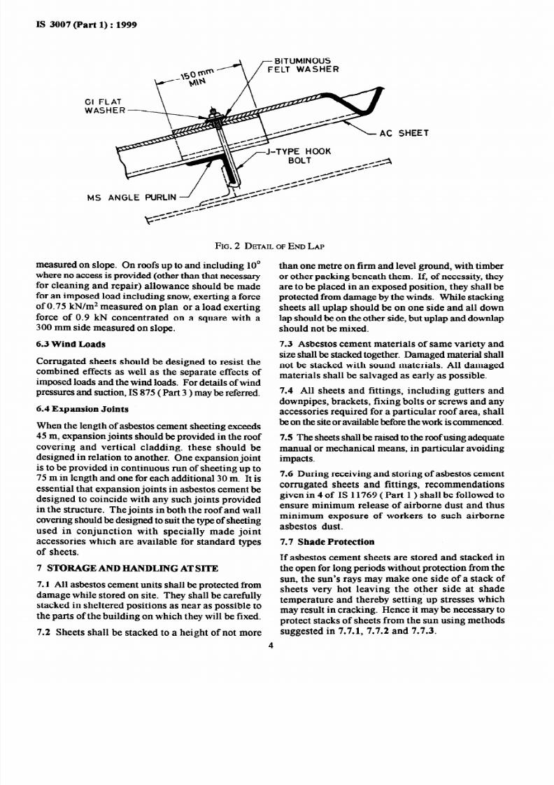
7232019 Is-3007_1 - Laying of Asbestos Cement Sheets
httpslidepdfcomreaderfullis-30071-laying-of-asbestos-cement-sheets 1724
IS 3007(Part1)1999
J-TYFE
SIDE CLADDING
APRON PIECE
LEAN-TO ROOF1
STANCHION -
FIG 17 CORRUGATED PRONPIKE
7232019 Is-3007_1 - Laying of Asbestos Cement Sheets
httpslidepdfcomreaderfullis-30071-laying-of-asbestos-cement-sheets 1824
IS 3007 (Part 1) 1999
rJ-TYPE HOOK BOLT
USED AS NORTH
LIGHT CURVE MUSHROOM HEADROOFING BOLT
REQUIRED ONLY IN
STORMY WIND REGIONS
BACK OF PRINCIPAL RAFTER-rsquo IANGLE WELDED AT THE
IS-TYPE lsquoLOUVRE
FIG18 TYPICAL CORRUGATEDNORTHLIGHTCURVES
i
-LOUVRE SUPPORTMS ANGLE OR FLAT
WASHERS
SECTION XX
LAPPING OF LOUVRES
FIG 19 TYPICALSrsquo TYPELOUVRE
7232019 Is-3007_1 - Laying of Asbestos Cement Sheets
httpslidepdfcomreaderfullis-30071-laying-of-asbestos-cement-sheets 1924
IS 3007(Part1)1999
J-TYPE HOOK BOLT
MS ANGLE PURLIN
OPENING IN T
MUSHROOROOFNG BOLTS
PLAN
FIG 20 TYPICALCOWLTYPEVENTILATOR
OPENING TO SUIT WIRED GLASS OF SIZES
68OxLOOx6 mm OR 800x 580x6 mm
FIG21 TYPICALROOFLIGHT
7232019 Is-3007_1 - Laying of Asbestos Cement Sheets
httpslidepdfcomreaderfullis-30071-laying-of-asbestos-cement-sheets 2024
IS 3007(Part1)1999
r USHROOM HEADROOFING BOLT
NORTHLIGHTIROOF TRUSS
ROOFLIGHT
WIRED GLASS
SEMI- CORRUGATEDAC SHEET
-AC GUTTER 1
FIG22 TYPICAL OOFLIGHTSEDASNORTHLIGHTLAZING1OOmm LAP
-
BARGE BOARD SECURED TO
SHEETS WITH MUSHROOM
HEAD ROOFING BOLTS
AND GI AND BITUMINOUS
FELT WASHERS-
MS ANGLE
PURLI N
ARGE BOARG AT VERGE
7232019 Is-3007_1 - Laying of Asbestos Cement Sheets
httpslidepdfcomreaderfullis-30071-laying-of-asbestos-cement-sheets 2124
IS 3007(Part1)1999
IS No
459 1991
730 1978
875(Part3)
1987
1120 1975
1626(Part2)
1980
ANNEX A
( C lause )
LIST OF REFERRED INDIAN STANDARDS
Title
Specification for unreinforced
corrugated and semi-corrugated
asbestos cement sheets ( second
revision )
Hook bolts for corrugated sheet
roofing ( second revision )
Code of practice for design loads
( other than earthquake ) for
buildings and structures Part 3
Wind loads ( second revision )
Coach screws (first revision )
Specification for asbestos cement
building pipes and pipe fitting
gutters and gutter fittings and roof
fittings Part 2 Gutters and gutter
fittings (first revision )
IS No
1626(Part3)
1980
20 1992
2098 1964
11769(Part 1)1987
13000 1990
13008 1990
fitle
Specification for asbestos cement
building pipes and pipe fitting
gutters and gutter fittings and roof
fittings Part 3 Roofing accessories
(first revision )
Specification for asbestos cement
flat sheets (first revision )
Specification for asbestos cement
building boards
Guidelines for safe use of productscontaining asbestos Part 1 Asbestos
cement products
Specification for silica asbestos
cement flat sheets
Specification for shallow corrugated
asbestos cement sheets
19
7232019 Is-3007_1 - Laying of Asbestos Cement Sheets
httpslidepdfcomreaderfullis-30071-laying-of-asbestos-cement-sheets 2224
IS 3007 (Part 1) 1999
ANNEX B
( Foreword )
COMMlTIrsquoEE COMFOSlTION
Cement Matrix Products Sectional Committee CED 53
Chairman Representing
SHRI S A REDDI
Members
Gammon India Ltd Mumbai
SHRI 0 P AGARWAL
SHRI J L DHINGRA (Alfernate)
SHRI M A AZEEZ
SHRI P D GAIKAWAD (Alternate)
SHRI G R BHARITKAR
COL (RETD) D V PADSALGIKAR(Alternate)
SHRI A K CHADHA
SHRI J R SIL (Alternate)
CHIEF ENGINEER
DY CHIEF ENGINEER (Alternate)
SHRI K H GANGWAL
SHRI V PA~AEHI (Alternafe)
SHRI S HARIRAMASAMY
SHRI P S KALANI
Municipal Corporation of Delhi Delhi
Rural Electrification Corporation Ltd New Delhi
BG Shirke Construction Technology Pvt Ltd Pune
Hindustan Prefab Ltd New Delhi
Municipal Corporation of Greater Bombay Mumbai
Hyderabad Industries Ltd Sanatnagar
Tamil Nadu Water Supply amp Drainage Board Chennai
All India Small Scale AC Pressure Pipes Manufacturers
Association Hyderabad
SHRI N KISHAN REDDY (Alternate)
SHRI D K KANUNGO
SHRI T CHOUDHURY(Alternate)
JOINT DIRECTOR STANDARDS B amp S ) CB II
ASSIT DESIGN ENGINEER (CS-I) (Alternate)
SHRI P D KELKAR
SHRI P R C NAIR (Alternate)
SHRI A K MANI
DR IRSAD MASOOD
SHRI S P TEHRI (Alternate)
DR C RAIKUMAR
SHRI H K JULKA (Alternate)
SHRI B V B PAI
SHRI M G DANDWATE Alternate)
SHRI S P RASTOGI
SHRI G S SHIRLAKAR
National Test House Calcutta
Research Design and Standards Organization Lucknow
Indian Hume Pipe Co Ltd Mumbai
Structural Engineering Research Centre Chennai
Central Building Research Institute Roorkee
National Council for Cement and Building Materials New Delhi
The Associated Cement Companies Ltd Thane
Federation of U P Pipe Manufacturers Lucknow
Spun Pipes Manufacturers Association of Maharashtra (SSI)
PunsSHRI A V GOGTE (Alternate)
SHRI P S ROY
DR A S GOYAL (Alternate)
SHRI K SRIVASTAVA
SHRI R SUBRAUANIAM
SHRI K P ABIUHAM (Alternate)
SHRI C H SUEIIUMANIAN
SHRI A D~TTA (Alternate)
SHRI VINOD KUMAR
Director (Civ Engg)
Engineer-in-Chiefrsquos Branch Army Headquarters New Delhi
Eternit Everest Ltd Mumbai
Central Public Works Department New Delhi
Small Scale Industries New Delhi
Director General BIS (Ex-oflcio Member)
Member Secretary
SHRI J K PRASAD
Add1 Director (Civ Engg) BIS
20
( Continued on page 21 )
7232019 Is-3007_1 - Laying of Asbestos Cement Sheets
httpslidepdfcomreaderfullis-30071-laying-of-asbestos-cement-sheets 2324
IS 3007(Part1)1999
( Continued fr om page 20 )
Fibre Reinforced Cement Products Subcommittee CED 53 1
Convener
DRC AJKUMAR
Members
Representing
National Council for Cement and Building Materials New Delhi
SHRIS BANERJEE National Test House Calcutta
SHRISN ASU Directorate General of Supplies and Disposals New Delhi
SHRIT N UBOVEJAAlternate)
SHRIN G BHASAK Directorate General of Technical Development New Delhi
SHRIP K JAIN Alternate)
DR KALYAN AS Central Building Research Institute Roorkee
SHRIR S RAWATAlternate)
JOINTDIRECTORTANDARDSB amp S )CB-I Research Design and Standards Organization Lucknow
JOINTDIRECTORTANDARDSB amp S )CB-II (Affernate)
SUPERINTENDINGNGINEERTADC) Central Public Works Department New Delhi
EXECUTIVENGINEERTADC) (Alternate)
SHRIS GANAPATHY Ramco Industries Ltd Chennai
SHRIK P GOENKA Sabarmangala Industries Calcutta
SHRII P GOENKAAlternate)
SHRISRINIVASAN IYER Eternit Everest Ltd New Delhi
DR V B UPADHYAYAlternate)
SHRI P L JAIN Jain Trading Corporation Kota
SHRIM M JAIN Alfernufe)
SHRIP SKALANI Kalani Asbestos Cement Pvt Ltd Indore
SHRIT S SUMMIAlternate)
SHRIP S KALANI AlI India Small Scale AC Pipe Manufacturerrsquos Association
Hyderabad
SHRIN KRISHAN EDDI M ternate)
SHRIRAJ KUMAR Development Commissioner Small Scale Industries New DelhiSHRIS C UMARAlternate)
SHRIP N MEHTA Geological Survey of India Jaipur
SHRIV K KASLIWALAlternate)
SHRIV PAT~ABHI The Hyderabad Industries Ltd Hyderabad
SHRIA K UPTAAlternate)
DR N RAGHAVENDRA National Council for Cement and Building Materials New Delhi
COLV K SAWHNEY Engineer-in-Chiefrsquos Branch New Delhi
LT COL R L KRIRE Alternate)
SHRIK VENKATACHELAM Central Soil amp Materials Research Station New Delhi
SHRIN CHANDRASEKARANAfternate)
SHRIU N VENKATESH Shree Divijay Cement Co Ltd Ahmadabad
SHRIK S RAMAKRISHANANAlternate)
21
7232019 Is-3007_1 - Laying of Asbestos Cement Sheets
httpslidepdfcomreaderfullis-30071-laying-of-asbestos-cement-sheets 2424
Bureati of Indian Standards
BIS is a statutory institution established under the Bureau of ndi an Standar ds Act 1986 l o promote harmonious
develapment of the activities of standardization marking and quality certification of goods and attending to
connected matters in the country
Copyright
BIS has the copyright of all its publications No part of these publications may be reproduced in any form without
the prior permission in writing of BIS This does not preclude the free use in the course of implementing the
standard of necessary details such as symbols and sizes type or grade designations Enquiries relating tocopyright be addressed to the Director (Publications) BIS
Review of Indian Standards
Amendments are issued to standards as the need arises on the basis of comments Standards-are also reviewed
periodically a standard along with amendments is reaffirmed when such review indicates that no changes are
needed if the review indicates that changes are needed it is taken up for revision Users of Indian Standards
should ascertain that they are in possession of the latest amendments or editionby referring to the latest issue
of lsquoBIS Handbookrsquo and lsquoStandards Monthly Additionsrsquo
This Indian Standard has been developed from Dot No CED 53 ( 495 1)
Amendments Issued Since Publication
Amend No Date of Issue Text Affected
Headquarters
BUREAU OF INDIAN STANDARDS
Manak Bhavan 9 Bahadur Shah Zafar Marg New Delhi 1 lOQO2Telephones 323 01 31 323 94 02 323 33 75
Regional Offices
Central Manak Bhavan 9 Bahadur Shah Zafar Marg
NEW DELHI 110002
Telegrams Manaksanstha
( Common to
all offices )
Telephone
323 76 17
323 38418
Eastern l14 C I T Scheme VII M V I P Road Maniktola
CALCUTTA 700054
Northern SC0 335-336 Sector 34-A CHANDIGARH 160022
Southern C I T Campus IV Cross Road CHENNAI 6QO113
I 337 84 99337 85 61
337 86 26 337 86 62
1 60 38 43
60 20 25
I
23502162350442
235 15 19235 23 15
Western Manskalaya E9 MIDC Marol Andheri (East)MUMBAI 400093
83292958327858
83278918327892
Branches AHMADABAD BANGALORE BHOPAL BHUBANESHWAR
COIMBATORE FARIDABAD GHAZIABAD GUWAHATI HYDERABAD JAIPUR
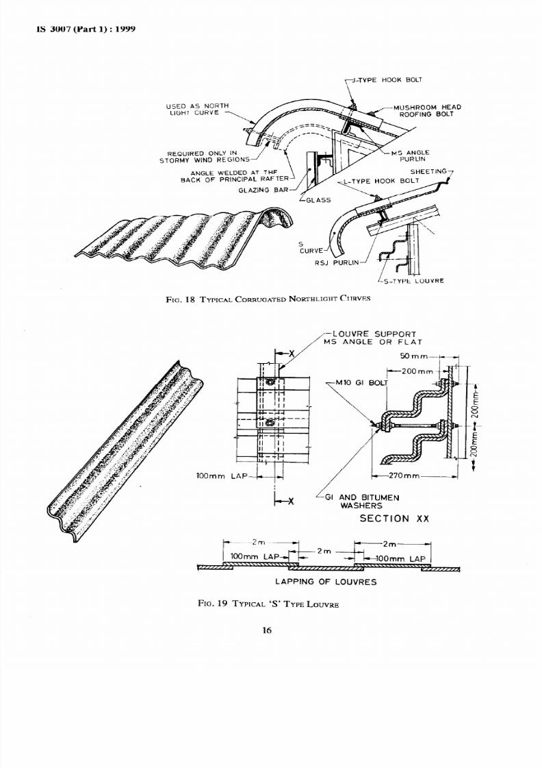
7232019 Is-3007_1 - Laying of Asbestos Cement Sheets
httpslidepdfcomreaderfullis-30071-laying-of-asbestos-cement-sheets 2324
IS 3007(Part1)1999
( Continued fr om page 20 )
Fibre Reinforced Cement Products Subcommittee CED 53 1
Convener
DRC AJKUMAR
Members
Representing
National Council for Cement and Building Materials New Delhi
SHRIS BANERJEE National Test House Calcutta
SHRISN ASU Directorate General of Supplies and Disposals New Delhi
SHRIT N UBOVEJAAlternate)
SHRIN G BHASAK Directorate General of Technical Development New Delhi
SHRIP K JAIN Alternate)
DR KALYAN AS Central Building Research Institute Roorkee
SHRIR S RAWATAlternate)
JOINTDIRECTORTANDARDSB amp S )CB-I Research Design and Standards Organization Lucknow
JOINTDIRECTORTANDARDSB amp S )CB-II (Affernate)
SUPERINTENDINGNGINEERTADC) Central Public Works Department New Delhi
EXECUTIVENGINEERTADC) (Alternate)
SHRIS GANAPATHY Ramco Industries Ltd Chennai
SHRIK P GOENKA Sabarmangala Industries Calcutta
SHRII P GOENKAAlternate)
SHRISRINIVASAN IYER Eternit Everest Ltd New Delhi
DR V B UPADHYAYAlternate)
SHRI P L JAIN Jain Trading Corporation Kota
SHRIM M JAIN Alfernufe)
SHRIP SKALANI Kalani Asbestos Cement Pvt Ltd Indore
SHRIT S SUMMIAlternate)
SHRIP S KALANI AlI India Small Scale AC Pipe Manufacturerrsquos Association
Hyderabad
SHRIN KRISHAN EDDI M ternate)
SHRIRAJ KUMAR Development Commissioner Small Scale Industries New DelhiSHRIS C UMARAlternate)
SHRIP N MEHTA Geological Survey of India Jaipur
SHRIV K KASLIWALAlternate)
SHRIV PAT~ABHI The Hyderabad Industries Ltd Hyderabad
SHRIA K UPTAAlternate)
DR N RAGHAVENDRA National Council for Cement and Building Materials New Delhi
COLV K SAWHNEY Engineer-in-Chiefrsquos Branch New Delhi
LT COL R L KRIRE Alternate)
SHRIK VENKATACHELAM Central Soil amp Materials Research Station New Delhi
SHRIN CHANDRASEKARANAfternate)
SHRIU N VENKATESH Shree Divijay Cement Co Ltd Ahmadabad
SHRIK S RAMAKRISHANANAlternate)
21
7232019 Is-3007_1 - Laying of Asbestos Cement Sheets
httpslidepdfcomreaderfullis-30071-laying-of-asbestos-cement-sheets 2424
Bureati of Indian Standards
BIS is a statutory institution established under the Bureau of ndi an Standar ds Act 1986 l o promote harmonious
develapment of the activities of standardization marking and quality certification of goods and attending to
connected matters in the country
Copyright
BIS has the copyright of all its publications No part of these publications may be reproduced in any form without
the prior permission in writing of BIS This does not preclude the free use in the course of implementing the
standard of necessary details such as symbols and sizes type or grade designations Enquiries relating tocopyright be addressed to the Director (Publications) BIS
Review of Indian Standards
Amendments are issued to standards as the need arises on the basis of comments Standards-are also reviewed
periodically a standard along with amendments is reaffirmed when such review indicates that no changes are
needed if the review indicates that changes are needed it is taken up for revision Users of Indian Standards
should ascertain that they are in possession of the latest amendments or editionby referring to the latest issue
of lsquoBIS Handbookrsquo and lsquoStandards Monthly Additionsrsquo
This Indian Standard has been developed from Dot No CED 53 ( 495 1)
Amendments Issued Since Publication
Amend No Date of Issue Text Affected
Headquarters
BUREAU OF INDIAN STANDARDS
Manak Bhavan 9 Bahadur Shah Zafar Marg New Delhi 1 lOQO2Telephones 323 01 31 323 94 02 323 33 75
Regional Offices
Central Manak Bhavan 9 Bahadur Shah Zafar Marg
NEW DELHI 110002
Telegrams Manaksanstha
( Common to
all offices )
Telephone
323 76 17
323 38418
Eastern l14 C I T Scheme VII M V I P Road Maniktola
CALCUTTA 700054
Northern SC0 335-336 Sector 34-A CHANDIGARH 160022
Southern C I T Campus IV Cross Road CHENNAI 6QO113
I 337 84 99337 85 61
337 86 26 337 86 62
1 60 38 43
60 20 25
I
23502162350442
235 15 19235 23 15
Western Manskalaya E9 MIDC Marol Andheri (East)MUMBAI 400093
83292958327858
83278918327892
Branches AHMADABAD BANGALORE BHOPAL BHUBANESHWAR
COIMBATORE FARIDABAD GHAZIABAD GUWAHATI HYDERABAD JAIPUR