is 2063-1 (2002): test code for machine tools, part 1 ... · is 2063-1 (2002): test code for...
TRANSCRIPT

Disclosure to Promote the Right To Information
Whereas the Parliament of India has set out to provide a practical regime of right to information for citizens to secure access to information under the control of public authorities, in order to promote transparency and accountability in the working of every public authority, and whereas the attached publication of the Bureau of Indian Standards is of particular interest to the public, particularly disadvantaged communities and those engaged in the pursuit of education and knowledge, the attached public safety standard is made available to promote the timely dissemination of this information in an accurate manner to the public.
इंटरनेट मानक
“!ान $ एक न' भारत का +नम-ण”Satyanarayan Gangaram Pitroda
“Invent a New India Using Knowledge”
“प0रा1 को छोड न' 5 तरफ”Jawaharlal Nehru
“Step Out From the Old to the New”
“जान1 का अ+धकार, जी1 का अ+धकार”Mazdoor Kisan Shakti Sangathan
“The Right to Information, The Right to Live”
“!ान एक ऐसा खजाना > जो कभी च0राया नहB जा सकता है”Bhartṛhari—Nītiśatakam
“Knowledge is such a treasure which cannot be stolen”
“Invent a New India Using Knowledge”
है”ह”ह
IS 2063-1 (2002): Test Code for Machine Tools, Part 1:Geometric Accuracy of Machines Operating Under No-load orFinishing Conditions [PGD 3: Machine Tools]


IS 2063 (Part 1) :2002
W’?i+hmISO 230-1 :1996
n \\J-l?ll’-f 3-HUH<) ‘a T&PmiRm
wJllwHn??RnFm lfwml RTRRit ihFFPf3
31=lTm#mE$h?M *mfMvd%JGd T
Indian Standard
TEST CODE FOR MACHINE TOOLSPART 1 GEOMETRIC ACCURACY OF MACHINES OPERATING
UNDER NO-LOAD OR FINISHING CONDITIONS
(Second Revision)
ICS 25.080.01
@ BIS 2002
BUREAU OF INDIAN STANDARDSMANAK BHAVAN, 9 BAHADUR SHAH ZAFAR MARG
NEW DELHI 110002
December 2002 Price Group 15
Machine Tools Sectional Committee, BP 03
NATiONAL FOREWORD
This Indian Standard (Part 1) (Second Revision) which is identical with ISO 230-1:1996 ‘Test code formachine tools — Part 1:Geometric accuracy of machines operating under no-load or finishing conditions’issued by th~ International Organization for Standardization (ISO) was adopted by the Bureau of IndianStandards on the recommendation of the Machine Tools Sectional Committee and approval of the Basicand Production Engineering Division Council.
Originally, IS 2063 ‘Code for testing machine tools’ was formulated in 1962 and was based on Draft ISOrecommendations No. 283 Machine tool test code (revised text). With the advancement in technologyand the experience gained in the field of machine tools. ISO has published ISO 230-1:1986.Consequently, first revision of IS 2063 was published in 1988 to align it with ISO 230-1:1986 in orderto keep pace with the international technology. This second revision has been taken up to align thisstandard with ISO 230-1:1996 which has been technically revised and is now published as Parl 1 ofIS 2063.
ISO 230 consists of the following parts under the general title ‘Test code for machine tools’ —
Part 1: Geometric accuracy of machines operating under no-load or finishing conditions
Part 2: Determination of accuracy and repeatability of positioning of numerically controlled machinetool axes
Part 3: Evaluation of thermal effects
Part 4: Circular tests for numerically controlled machine tools
Part 5: Determination of noise emission
The other parts are under consideration with Machine Tools Sectional Committee for adoption as otherparts of IS 2063.
The text of the ISO Standard has been approved as suitable for publication as Indian Standard withoutdeviations. Certain conventions are, however, not identical to those used in Indian Standards. Attentionis particularly drawn to the following:
a) Wherever the words ‘International Standard’ appear referring to this standard, they should beread as ‘Indian Standard’.
b) Comma (,) has been used as a decimal marker in the International Standard while in IndianStandards, the current practice is to use a point (.) as the decimal marker.
c) Where ‘American taper 7/24’ appears; it may be read as ‘Self release 7/24 taper’.
d) Wherever in respect of ‘Measuring instrument’ reference to lSO/TC 3 ‘Limits and fits’ has beenmade, it may be read as reference to the national committee, BP 25 ‘Engineering Meteorology’.
e) Conical shank of Morse taper may be read according to IS 1715:1987 ‘Self holding tapers(second revision)’.
Contents have been listed for easy reference in this standard.
For the purpose of deciding whether a particular requirement of this standard is complied with, the finalvalue, observed or calculated, expressing the result of a test or analysis shall be rounded off inaccordance with IS 2:1960 ‘Rules for rounding off numerical values (revised)’. The number of significantplaces retained in the rounded off value should be the same as that of the specified value in thisstandard.

IS 2063 (Part l) :2002
ISO 230-1 :1996
Contents
Page
1 Scope . . . . . . . . . . . . . . . . . . . . . . . . . . . . . . . . . . . . . . . . . . . . . . . . . . . . . . . . . . . . . . . . . . . . . .
2 General considerations . . . . . . . . . . . . . . . . . . . . . . . . . . . . . . . . . . . . . . . . . . . . . . . . . .
2.1 Definitions relating togeometric tests . . . . . . . . . . . . . . . . . . . . . . . . . . . . . .
2.2 Test methods and use of measuring instruments . . . . . . . . . . . . . . . . .
2.3 Tolerances . . . . . . . . . . . . . . . . . . . . . . . . . . . . . . . . . . . . . . . . . . . . . . . . . . . . . . . . . . . . . .
2.31 Tolerances on measurements when testing machine tools . . . . .
2.311 Units of measurement and measuring ranges . . . . . . . . . . . . . . . . . .
2.312 Rules concerning tolerances . . . . . . . . . . . . . . . . . . . . . . . . . . . . . . . . . . . . . . .
2.32 Subdivisions of tolerances . . . . . . . . . . . . . . . . . . . . . . . . . . . . . . . . . . . . . . . . . .
2.321 Tolerances applicable to test pieces and to, individualcomponents of machine tools . . . . . . . . . . . . . . . . . . . . . . . . . . . . . . . . . . . . .
2.321.1 Tolerances of dimension . . . . . . . . . . . . . . . . . . . . . . . . . . . . . . . . . . . . . . . . .
2.321.2 Tolerances of form . . . . . . . . . . . . . . . . . . . . . . . . . . . . . . . . . . . . . . . . . . . . . . .
2.321.3 Tolerances of position . . . . . . . . . . . . . . . . . . . . . . . . . . . . . . . . . . . . . . . . . . . .
2.321.4 Influence of errors of form in determining positional errors.
2.321.5 Local tolerances . . . . . . . . . . . . . . . . . . . . . . . . . . . . . . . . . . . . . . . . . . . . . . . . . . .
2.322 Tolerances applicable to the displacement of a component ofa machine tool . . . . . . . . . . . . . . . . . . . . . . . . . . . . . . . . . . . . . . . . . . . . . . . . . . . . . . .
2.322.1 Tolerances of positioning . . . . . . . . . . . . . . . . . . . . . . . . . . . . . . . . . . . . . . . .
2.322.11 Tolerances ofrepeatatili~ . . . . . . . . . . . . . . . . . . . . . . . . . . . . . . . . . . . . .
2.322.2 Tolerances of the form oftrajecto~ . . . . . . . . . . . . . . . . . . . . . . . . . . . .
2.322.3 Tolerances of relative position of straight-line motion.., . . . . .
2.322.4 Local tolerance of displacement of a component . . . . . . . . . . . . .
2.323 Overall or inclusive tolerances . .. . . . . . . . . . . . . . . . . . . . . . . . . . . . . . . . . . .
1
1
1
1
2
2
2
2
2
2
2
3
3
3
3
4
4
4
4
4
5
5

IS 2063 (Part 1) :2002
IS() 230-1 :1996
2.324 Symbols and positions of tolerances for relative angularpositions ofaxes, slideways, etc. . . . . . . . . . . . . . . . . . . . . . . . . . . . . . . . .
2.325 Conventional definition of the axes and of the movements . . .
3 Prelimina~ operations . . . . . . . . . . . . . . . . . . . . . . . . . . . . . . . . . . . . . . . . . . . . . . . . . . .
3.1 installation of themachine before test . . . . . . . . . . . . . . . . . . . . . . . . . . . . . .
3.11 Levelling . . . . . . . . . . . . . . . . . . . . . . . . . . . . . . . . . . . . . . . . . . . . . . . . . . . . . . . . . . . . . . .
3.2 Conditions of themachine before test . . . . . . . . . . . . . . . . . . . . . . . . . . . . . .
3.21 Dismantling ofceRain components . . . . . . . . . . . . . . . . . . . . . . . . . . . . . . . .
3.22 Temperature conditions of certain components before test,..
3.23 Functioning andloading . . . . . . . . . . . . . . . . . . . . . . . . . . . . . . . . . . . . . . . . . . . . ..
4 Machining tests . . . . . . . . . . . . . . . . . . . . . . . . . . . . . . . . . . . . . . . . . . . . . . . . . . . . . . . . . .
4.1 Testing . . . . . . . . . . . . . . . . . . . . . . . . . . . . . . . . . . . . . . . . . . . . . . . . . . . . ... . . . . . . . . . . . .
4.2 Checking of workplaces in machining tests . . . . . . . . . . . . . . . . . . . . . . . .
5 Geometric tests . . . . . . . . . . . . . . . . . . . . . . . . . . . . . . . . . . . . . . . . . . . . . . . . . . . . . . . . . .
5.1 General . . . . . . . . . . . . . . . . . . . . . . . . . . . . . . . . . . . . . . . . . . . . . . . . . . . . . . . . . . . . . . . . . .
5.2 Straightness . . . . . . . . . . . . . . . . . . . . . . . . . . . . . . . . . . . . . . . . . . . . . . . . . . . . . . . . . . . .
5.21 Straightness ofaline inaplane orinspace . . . . . . . . . . . . . . . . . . . . . . .
5.211 Definition . . . . . . . . . . . . . . . . . . . . . . . . . . . . . . . . . . . . . . . . . . . . . . . . . . . . . . . . . . . . .
5.211.1 Straightness ofaline ina plane . . . . . . . . . . . . . . . . . . . . . . . . . . . . . . . . .
5.211.2 Straightness ofaline inspace . . . . . . . . . . . . . . . . . . . . . . . . . . . . . . . . . .
5.212 Methods of measurement of straightness . . . . . . . . . . . . . . . . . . . . . .
5.212.1 Methods based on the measurement of length . . . . . . . . . . . . . .
5.212.11 Straightedge method . . . . . . . . . . . . . . . . . . . . . (formerly 5.212.1)
5.212.111 Measurement inavetiical plane . . . . . . . . . . . . . . . . . . . . . . . . . . . . .
5.212.112 Measurement inahotizontal plane . . . . . . . . . . . . . . . . . . . . . . . . . .
5.212.12 Taut-wire and microscope method . . . . . . (formerly 5.21 2.3)
5.212.13 Alignment telescope method . . . . . . . . . . . . . . . . . . . . . . . . . . . . . . . . . .
5.212.14 Alignment laser technique . . . . . . . . . . . . . . . . . . . . . . . . . . . . . . . . . . . . .
5.212.15 Laser intederomet~" technique . . . . . . . . . . . . . . . . . . . . . . . . . . . . . . . .
5.212.2 Methods based on the measurement of angles . . . . . . . . . . . . . .
5.212.21 Precision level method . .. . . . . . . . . . . . . . . . . . . . . . . . . . . . . . . . . . . . . . .
5.212.22 Autocollimation method . . . . . . . . . . . . . . . . . . . . . . . . . . . . . . . . . . . . . . . .
5.212.23 Method by laser interferometer (angle measurement) . . . . .
5.213 Tolerance . . . . . . . . . . . . . . . . . . . . . . . . . . . . . . . . . . . . . . . . . . . . . . . . . . . . . . . . . . . . .
5.213.1 Definition . . . . . . . . . . . . . . . . . . . . . . . . . . . . . . . . . . . . . . . . . . . . . . . . . . . . . . . . . . .
5.213.2 Determination of tolerance . . . . . . . . . . . . . . . . . . . . . . . . . . . . . . . . . . . . . .
5.22 Straightness of components . . . . . . . . . . . . . . . . . . . . . . . . . . . . . . . . . . . . . . . .
5L221 Definition . . . . . . . . . . . . . . . . . . . . . . . . . . . . . . . . . . . . . . . . . . . . . . . . . . . . . . . . . . . . .
5.222 Methods of straightness measurement . . . . . . . . . . . . . . . . . . . . . . . . ..
5
5
5
5
5
5
5
5
6
6
6
6
6
6
6
7
7
7
7
7
7
8
8
8
9
10
10
10
11
11
12
12
13
13
la
13
13
13
.ii

IS 2063 (Part l) :20021S0 230-1 :1996
5.222.1 Reference grooves or reference surface of tables . . . . . . . . . . . .
5.222.2 . Slideways . . . . . . . . . . . . . . . . . . . . . . . . . . . . . . . . . . . . . . . . . . . . . . . . . . . . . . . . . .
5.222.21 Vee surfaces . . . . . . . . . . . . . . . . . . . . . . . . . . . . . . . . . . . . . . . . . . . . . . . . . . . . .
5.222.22 Cylindrical surfaces . . . . . . . . . . . . . . . . . . . ... . . . . . . . . . . . . . . . . . . . . . . . . .
5.222.23 Single vetiical sudaces . . . . . . . . . . . . . . . . . . . . . . . . . . . . . . . . . . . . . . . . .
5.222.24 Slant.bed configuration . . . . . . . . . . . . . . . . . . . . . . . . . . . . . . . . . . . . . . . . .
5.222.3 Tolerances . . . . . . . . . . . . . . . . . . . . . . . . . . . . . . . . . . . . . . . . . . . . . . . . . . . . . . . . .
5.23 Straight.line motion . . . . . . . . . . . . . . . . . . . . . . . . . . . . . . . . . . . . . . . . . . . . . . . . . . .
5.231 Definitions . . . . . . . . . . . . . . . . . ... . . . . . . . . . . . . . . . . . . . . . . . . . . . . . . . . . . . . . . . . .
5.231.1 Positional deviations . . . . . . . . . . . . . . . . . . . . . . . . . . . . . . . . . . . . . . . . . . . . . .
5.231.2 Linear deviations . . . . . . . . . . . . . . . . . . . . . . . . . . . . . . . . . . . . . . . . . . . . . . . . . .
5.231.3 Angular deviations . . . . . . . . . . . . . . . . . . . . . . . . . . . . . . . . . . . . . . . . . . . . . . . .
5.232 Methods of measurement . . . . . . . . . . . . . . . . . . . . . . . . . . . . . . . . . . . . . . . . .
5.232.1 Methods of measurement of linear deviations . . . . . . . . . . . . . . . .
5.232.11 Method with a straightedge and a dialgauge . . . . . . . . . . . . . . . . . . . . . . . . . . . . . . . . . . . . (formerly 5.232.1 )
5.232.12 Method with microscope and taut-wire . . . . . . . . . . . . . . . . . . . . . . . . . . . . . . . . . . . . . . . . (formerly 5.232.2)
5.232.13 Method using an alignment telescope . . . . . . . . . . . . . . . . . . . . . .
5.232.14 Method using a laser . . . . . . . . . . . . . . . . . . . . . . . . . . . . . . . . . . . . . . . . . .
5.232.15 Method using angle measurements . . . . . . . . . . . . . . . . . . . . . . . .
5.232.2 Methods of measurement of angular deviation . . . . . . . . . . . . . . .
5.232.21 Method using a precision level . . . . . . . . . . . . . . . . . . . . . . . . . . . . . . .
5.232.22 Method using an autocollimator . .. . . . . . . . . . . . . . . . . . . . . . . . . . .
5.232.23 Method using a laser . . . . . . . . . . . . . . . . . . . . . . . . . . . . . . . . . . . . . . . . . .
5.233 Tolerance . . . . . . . . . . . . . . . . . . . . . . . . . . . . . . . . . . . . . . . . . . . . . . . . . . . . . . . . . . . . .
5.233.1 Tolerance for the linear deviation of straight-line motion . . . .
5.233.2 Tolerance for the angular deviation of straight-line motion..
5.3 Flatness . . . . . . . . . . . . . . . . . . . . . . . . . . . . . . . . . . . . . . . . . . . . . . . . . . . . . . . . . . . . . . . . .
5.31 Definition . . . . . . . .. . . . . . . . . . . . . . . . . . . . . . . . . . . . . . . . . . . . . . . . . . . . . . . . . . . . . . .
5.32 Methods of measurement . . . . . . . . . . . . . . . . . . . . . . . . . . . . . . . . . . . . . . . . . . .
5.321 Measurement of flatness by means of a surface plate . . . . . . . . .
5.321.1 Measurement by means of a surface plate and a dialgauge . . . . . . . . . . . . . . . . . . . . . . . . . . . . . . . . . . . . . . . . . . . . . . . . . . . . . . . . . . . . . . .
5.322 Measurement of flatness by means of straightedge(s) . . . . . . . .
5.322.1 Measurement by means of a family of straight lines bydisplacement of a straightedge . . . . . . . . . . . . . (formerly 5.322)
5.322.2 Measurement by means of straightedges, a precisionlevel andadia! gauge . . . . . . . . . . . . . . . . . . . . . . . . . . . . . . . . . . . . . . . . . . . . .
5.323 Measurement of flatness by means of a precision level . . . . . . .
5.323.1 Measurement of a rectangular surface . . . . . . . . . . . . . . . . . . . . . . . .
5.323.2 Measurement of plane surfaces with circular contours . . . . . .
5.324 Measurement of flatness by optical methods . . . . . . . . . . . . . . . . . . .
14
14
14
15
15
15
15
15
15
15
16
16
16
16
16
16
16
16
16
17
17
17 ‘
17
17
?7
17
17
17
17
17
18
18
18
19
19
19
20
.Ill

IS 2063 (Part 1) :2002ISO 230-~ :1996
5.324.1 Measurement byan autocollimator . . . . . . . . . . . . . . . . . . . . . . . . . . . .
‘5.324.2 Measurement by a sweep optical square.. . . . . . . . . . . . . . . . . . . .
5.324.3 Measurement byan alignment laser . . . . . . . . . . . . . . . . . . . . . . . . . . .
5.324.4 Measurement by a laser measuring system . . . . . . . . . . . . . . . . . .
5.325 Measurement by a coordinate measuring machine . . . . . . . . . . . .
5.33 Tolerances. . . . . . . . . . . . . . . . . . . . . . . . . . . . . . . . . . . . . . . . . . . . . . . . . . . . . . . . . . . . .
5.4 Parallelism, equidistance and coincidence.. . . . . . . . . . . . . . . . . . . . . . . . .
5.41 Parallelism oflines and planes . . . . . . . . . . . . . . . . . . . . . . . . . . . . . . . . . . . . . .
5.411 Definitions . . . . . . . . . . . . . . . . . . . . . . . . . . . . . . . . . . . . . . . . . . . . . . . . . . . . . . . . . . .
5.412 Methods ofrneasurement . . . . . . . . . . . . . . . . . . . . . . . . . . . . . . . . . . . . . . . . .
5.412.1 General. foraxes . . . . . . . . . . . . . . . . . . . . . . . . . . . . . . . . . . . . . . . . . . . . . . . . .
5.412.2 Parallelism oftwo planes . . . . . . . . . . . . . . . . . . . . . . . . . . . . . . . . . . . . . . . .
5.412.2? Straightedge anddia! gauge . . . . . . . . . . . . . . . . . . . . . . . . . . . . . . . . . . .
5.412.22 Precision level method . . . . . . . . . . . . . . . . . . . . . . . . . . . . . . . . . . . . . . . . .
5.412.3 Parallelism oftwo axes . . . . . . . . . . . . . . . . . . . . . . . . . . . . . . . . . . . . . . . . . .
5.412.31 Plane passing through twoaxes . . . . . . . . . . . . . . . . . . . . . . . . . . . . . . .
5.412.32 Second plane perpendicular to the first . . . . . . . . . . . . . . . . . . . . . . .
5.412.4 Parallelism ofanaxis toa plane . . . . . . . . . . . . . . . . . . . . . . . . . . . . . . . .
5.412.5 Parallelism of an axis to the intersection of two planes . . . . .
5.412.6 Parallelism of,the intersection of two planes to athird plane . . . . . . . . . . . . . . . . . . . . . . . . . . . . . . . . . . . . . . . . . . . . . . . . . . . . . . . . .
5.412.7 Parallelism between two straight lines, each formed by theintersection of two planes . . . . . . . . . . . . . . . . . . . . . . . . . . . . . . . . . . . . . . .
5.413 Tolerances . . . . . . . . . . . . . . . . . . . . . . . . . . . . . . . . . . . . . . . . . . . . . . . . . . . . . . . . . . .
5.42 Parallelism of motion . . . . . . . . . . . . . . . . . . . . . . . . . . . . . . . . . . . . . . . . . . . . . . . . .
5.421 Definitiorl . . . . . . . . . . . . . . . . . . . . . . . . . . . . . . . . . . . . . . . . . . . . . . . . . . . . . . . . . . . . .
5.422 Methods of measurement . . . . . . . . . . . . . . . . . . . . . . . . . . . . . . . . . . . . . . . . .
5.422.1 General . . . . . . . . . . . . . . . . . . . . . . . . . . . . . . . . . . . . . . . . . . . . . . . . . . . . . . . . . . . .
5.422.2 Parallelism. between a trajectory and a plane . . . . . . . . . . . . . . . . .
5.422.21 Plane is on the moving component itself . . . . . . . . . . . . . . . . . . . . .
5.422.22 Plane is not on the moving component itself . . . . . . . . . . . . . . . .
5.422.3 Parallelism ofatraject.o~ toanaxis . . . . . . . . . . . . . . . . . . . . . . . . . . . .
5.422.4 Parallelism of a trajectory to the intersection of twoplanes . . . . . . . . . . . . . . . . . . . . . . . . . . . . . . . . . . . . . . . . . . . . . . . . . . . . . . . . . . . . . .
5.422.5 Parallelism between two trajectories . . . . . . . . . . . . . . . . . . . . . . . . . .
5.423 Tolerance . . . . . . . . . . . . . . . . . . . . . . . . . . . . . . . . . . . . . . . . . . . . . . . . . . . . . . . . . . . . .
5.43 Equidistance . . . . . . . . . . . . . . . . . . . . . . . . . . . . . . . . . . . . . . . . . . . . . . . . . . . . . . . . . . .
5.431 Definition . . . . . . . . . . . . . . . . . . . . . . . . . . . . . . . . . . . . . . . . . . . . . . . . . . . . . . . . . . . . .
5,432 lMathods ofmeasurSment . . .. . . . . . . . . . . . . . . . . . . . . . . . . . . . . . . .. . . . . .
5.432.1 General . . . . . . . . . . . . . . . . . . . . . . . . . . . . . . . . . . . . . . . . . . . . . . . . . . . . . . . . . . . .
5.432.2 Special cdse of the equidistance of two axes from theplane ofpivoting ofoneof theaxes . . . . . . . . . . . . . . . . . . . . . . . . . . . .
5.433 Tolerance.,.. . . . . . . . . . . . . . . . . . . . . . . . . . . . . . . . . . . . . . . . . . . . . . . . . . . . . . . . . .
20
20
21
21
22
22
22
22
22
22
22
23
23
23
23
23
23
24
24
24
25
25
25
25
26
26
26
26
26
26
27
27
27
27
27
27
27
27
28
~.,,

K 2063 (Part 1) :2002
ISO 230-1 :1996
5.44 Coaxiality, coincidence oralignment . . . . . . . . . . . . . . . . . . . . . . . . . . . . . . .
5.441 Definition . . . . . . . . . . . . . . . . . . . . . . . . . . . . . . . . . . . . . . . . . . . . . . . . . . . . . . . . . . . . .
5.442 Method of measurement: . . . . . . . . . . . ... . . . . . . . . . . . . . . . . . . . . . . . . . . . . .
5.443 Tolerance . . . . . . . . . . . . . . . . . . . . . . . . . . . . . . . . . . . . . . . . . . . . . . . . . . . . . . . . . . . .
5.5 Squareness orperpendicularity . . . . . . . . . . . . . . . . . . . . . . . . . . . . . . . . . . . . . . .
5.51 Squareness of straight lines and planes . ... . . . . . . . . . . . . . . . . . . . . . . . .
5.511 Definition . . . . . . . . . . . . . . . . . . . . . . . . . . . . . . . . . . . . . . . . . . . . . . . . . . . . . . . . . . . . .
5.512 Methods of measurement . . . . . . . . . . . . . . . . . . . . . . . . . . . . . . . . . . . . . . . . .
5.512.1 General . . . . . . . . . . . . . . . . . . . . . . . . . . . . . . . . . . . . . . . . . . . . . . . . . . . . . . . . . . . . .
5.512.2 Twoplanes at900to each other . . . . . . . . . . . . . . . . . . . . . . . . . . . . . . . .
5.512.3 Twoaxes at900to each other . . . . . . . . . . . . . . . . . . . . . . . . . . . . . . . . . .
5.512.31 Themoaxes are fixed axes . . . . . . . . . . . . . . . . . . . . . . . . . . . . . . . . . . .
5.512.32 Oneofthe axes isanaxis of rotation . . . . . . . . . . . . . . . . . . . . . . . . .
5.512.4 Anaxisand aplaneat 900to each other . . . . . . . . . . . . . . . . . . . . . . .
5.512.41
5.512.42
5.512.5
5.512.51
5.512.52
5.512.6
5.512.7
Fixed axis . . . . . . . . . . . . . . . . . . . . . . . . . . . . . . . . . . . . . . . . . . . . . . . . . . . . . . . . .
his of rotation . . . . . . . ... . . . . . . . . . . . . . . . . . . . . . . . . . . . . . . . . . . . . . . . . . .
An axis at 90° to the intersection of two planes . . . . . . . . . . . . . .
Fixed axis . . . . . . . . . . . . . . . . . . . . . . . . . . . . . . . . . . . . . . . . . . . . . . . . . . . . . . . . .
tils of rotation . . . . . . . . . . ... . . . . . . . . . . . . . . . . . . . . . . . . . . . . . . . . . . . . . .
When the intersection of two planes is at 90° to anotherplane . . . . . . . . . . . . . . . . . . . . . . . . . . . . . . . . . . . . . . . . . . . . . . . . . . . . . . . . . . . . . . . .
When two straight lines, each formed bv the intersection oftwoplanes, are% 90°to each other . . . . . . . . . . . . . . . . . . . . . . . . . . .
5.513 Tolerance . . . . . . . . . . . . . . . . . . . . . . . ..# . . . . . . . . . . . . . . . . . . . . . . . . . . . . . . . . . . .
5.52 Perpendicularity of motion . . . . . . . . . . . . . . . . . . . . . . . . . . . . . . . . . . . . . . . . . . .
5.521 Definition . . . . . . . . . . . . . . . . . . . . . . . . . . . . . . . . . . . . . . . . . . . . . . . . . . . . . . . . . . . . .
5.522 Methods of measurement . . . . . . . . . . . . . . . . . . . . . . . . . . . . . . . . . . . . . . . . .
5.522.1 General . . . . . . . . . . . . . . . . . . . . . . . . . . . . . . . . . . . . . . . . . . . . . . . . . . . . . . . . . . . . .
5.522.2 Perpendicularity between the trajectory of a point andaplane . . . . . . . . . . . . . . . . . . . . . . . . . . . . . . . . . . . . . . . . . . . . . . . . . . . . . . . . . . . . .
5.522.3 Trajectory ofapoint at90°to an axis . . . . . . . . . . . . . . . . . . . . . . . . . .
5.522.4 Two trajectories perpendicular to each other . . . . . . . . . . . . . . . . .
5.523 Tolerance . . . . . . . . . . . . . . . . . . . . . . . . . . . . . . . . . . . . . . . . . . . . . . . . . . . . . . . . . . . . .
5.6 Rotation . . . . . . . . . . . . . . . . . . . . . . . . . . . . . . . . . . . . . . . . . . . . . . . . . . . . . . . . . . . . . . . . .
5.61 Run.out . . . . . . . . . . . . . . . . . . . . . . . . . . . . . . . . . . . . . . . . . . . . . . . . . . . . . . . . . . . . . . . .
5.611 Definitions . . . . . . . . . . . . . . . . . . . . . . . . . . . . . . . . . . . . . . . . . . . . . . . . . . . . . . . . . . . .
5.611.1 Out.of.round . . . . . . . . . . . . . . . . . ... . . . . . . . . . . . . . . . . . . . . . . . . . . . . . . . . . . . .
5.611.2 Eccentricity . . . . . . . . . . . . . . . . . . . . . . . . . . . . . . . . . . . . . . . . . . . . . . . . . . . . . . . .
5.611.3 Radial throw ofanaxis ata given point . . . . . . . . . . . . . . . . . . . . . . . .
5.611.4 Run-out of a component at a given section . . . . . . . . . . . . . . . . . . .
5.612 Methods of measurement . . . . . . . . . . . . . . . . . . . . . . . . . . . . . . . . . . . . . . . .
5.612.1 Precautions before testing . . . . . . . . . . . . . . . . . . . . . . ... . . . . . . . . . . . . . .
28
28
28
29
29
29
29
29
29
30
30
30
30
30
30
30
30
30
31
31
31
31
31
31
31
31
32
32
32
32
32
33
33
33
33
33
33
33
33
v

IS 2063 (Part 1) :20021S0 230-1 :1996
5.612.2 External sudace . . . . . . . . . . . . . . . . . . . . . . . . . . . . . . . . . . . . . . . . . . . . . . . . . .
5.612.3 internal surface . . . . . . . . . . . . . . . . . . . . . . . . . . . . . . . . . . . . . . . . . . . . . . . . . . .
5.613 Tolerance . . . . . . . . . . . . . . . . . . . . . . . . . . . . . . . . . . . . . . . . . . . . . . . . . . . . . . . . . . . . .
5.62 Periodic axial slip . . . . . . . . . . . . . . . . . . . . . . . . . . . . . . . . . . . . . . . . . . . . . . . . . . . .
5.621 Definitions . . . . . . . . . . . . . . . . . . . . . . . .. . . . . . . . . . . . . . . . . . . . . . . . . . . . . . . . . . .
5.621.1 Minimum axial play . . . . . . . . . . . . . . . . . . . . . . . . . . . . . . . . . . . . . . . . . . . . . . .
5.621.2 Petiodic axial slip . . . . . . . . . . . . . . . . . . . . . . . . . . . . . . . . . . . . . . . . . . . . . . . . . .
5.622 Methods of measurement . . . . . . . . . . . . . . . . . . . . . . . . . . . . . . . . . . . . . . . . .
5.622.1 General . . . . . . . . . . . . . . . . . . . . . . . . . . . . . . . . . . . . . . . . . . . . . . . . . . . . . . . . . . . . .
5.622.2 Applications . . . . . . . . . . . . . . . . . . . . . . . . . . . . . . . . . . . . . . . . . . . . . . . . . . . . . . . .
5.623
5.63
5.631
5.632
5.633
Tolerance . . . . . . . . . . . . . . . . . . . . . . . . . . . . . . . . . . . . . . . . . . . . . . . . . . . . . . . . . . . . .
Caroming . . . . . . . . . . . . . . . . . . . . . . . . . . . . . . . . . . . . . . . . . . . . . . . . . . . . . . . . . . . . .
Definitions . . . . . . . . . . . . . . . . . . . . . . . . . . . . . . . . . . . . . . . . . . . . . . . . . . . . . . . . . . .
Method of measurement . . . . . . . . . . . . . . . . . . . . . . . . . . . . . . . . . . . . . . . . . .
Tolerance . . . . . . . . . . . . . . . . . . . . . . . . . . . . . . . . . . . . . . . . . . . . . . . . . . . . . . . . . . . . .
6 Special tests . . . . . . . . . . . . . . . . . . . . . . . . . . . . . . . . . . . . . . . . . . . . . . . . . . . . . . . . . . . . . .
6.1 Division . . . . . . . . . . . . . . . . . . . . . . . . . . . . . . . . . . . . . . . . . . . . . . . . . . . . . . . . . . . . . . . . .
6.11
6.111
6.112
6.113
6.114
6.115
6.116
6.12
6.13
6.2
6.3
6.31
6.32
6.33
6.4
6.41
6.42
6.43
6.5
6.51
6.52
Definition of errors . . . . . . . . . . . . . . . . . . . . . . . . . . . . . . . . . . . . . . . . . . . . . . . . . .
Individual error of division . . . . . . . . . . . . . . . . . . . . . . . . . . . . . . . . . . . . . . . . . .
Successive error of division . . . . . . . . . . . . . . . . . . . . . . . . . . . . . . . . . . . . . . . .
Local error of division . . . . . . . . . . . . . . . . . . . . . . . . . . . . . . . . . . . . . . . . . . . . . . .
Cumulative error . . . . . . . . . . . . . . . . . . . . . . . . . . . . . . . . . . . . . . . . . . . . . . . . . . . .
Total error of division . . . . . . . . . . . . . . . . . . . . . . . . . . . . . . . . . . . . . . . . . . . . . . .
Graphical representation of these errors . . . . . . . . . . . . . . . . . . . . . . . . .
Methods of measurement . . . . . . . . . . . . . . . . . . . . . . . . . . . . . . . . . . . . . . . . .
Tolerance . . . . . . . . . . . . . . . . . . . . . . . . . . . . . . . . . . . . . . . . . . . . . . . . . . . . . . . . . . . .
determination of the linear positioning deviations of>crew-driven components . . . . . . . . . . . . . . . . . . . . . . . . . . . . . . . . . . . . . . . . . . .
4ngular play . . . . . . . . . . . . . . . . . . . . . . . . . . . . . . . . . . . . . . . . . . . . . . . . . . . . . . . . . . . .
Definition . . . . . . . . . . . . . . . . . . . . . . . . . . . . . . . . . . . . . . . . . . . . . . . . . . . . . . . . . . . . .
Method of measurement (testing of the indexingdevice/component) . . . . . . . . . . . . . . . . . . . . . . . . . . . . . . . . . . . . . . . . . . . . . . . . .
Tolerance . . . . . . . . . . . . . . . . . . . . . . . . . . . . . . . . . . . . . . . . . . . . . . . . . . . . . . . . . . . .
Repeatability of devices with angular indexing.. . . . . . . . . . . . . . . . . . .
Definition . . . . . . . . . . . . . . . . . . . . . . . . . . . . . . . . . . . . . . . . . . . . . . . . . . . . . . . . . . . . .
Method of measurement . . . . . . . . . . . . . . . . . . . . . . . . . . . . . . . . . . . . . . . . . .
Tolerance . . . . . . . . . . . . . . . . . . . . . . . . . . . . . . . . . . . . . . . . . . . . . . . . . . . . . . . . . . . .
intersection of axes . . . . . . . . . . . . . . . . . . . . . . . . . . . . . . . . . . . . . . . . . . . . . . . . . . .
Definition . . . . . . . . . . . . . . . . . . . . . . . . . . . . . . . . . . . . . . . . . . . . . . . . . . . . . . . . . . . . .
Methods of measurement . . . . . . . . . . . . . . . . . . . . . . . . . . . . . . . . . . . . . . . . .
6.521 Direct measurement . . . . . . . . . . . . . . . . . . . . . . . . . . . . . . . . . . . . . . . . . . . . . . . .
6.522 !ndirect measurement . . . . . . . . . . . . . . . . . . . . . . . . . . . . . . . . . . . . . . . . . . . . . .
6.53 Tolerance . . . . . . . . . . . . . . . . . . . . . . . . . . . . . . . . . . . . . . . . . . . . . . . . . . . . . . . . .
vi
34
34
34
35
35
35
35
35
35
35
35
36
36
36
36
37
37
37
37
37
37
37
37
37
39
39
39
39
39
39
39
39
39
40
40
40
40
40
,40
40
40

IS 2063 (Part l) :2002ISO 230-1”:1996
6.6 Circularity . . . . . . . . . . . . . . . . . . . . . . . . . . . . . . . . . . . . . . . . . . . . . . . . . . . . . . . . . . . . . . .
6.61 Definition . . . . . . . . . . . . . . . . . . . . . . . . . . . . . . . . . . . . . . . . . . . . . . . . . . . . . . . . . . . . . . .
6.62 Methods ofmeasurement on test pieces . . . . . . . . . . . . . . . . . . . . . . . . .
6.621
6.622
6.623
6.624
6.63
6.631
6.632
6.633
Circularity measuring machine with rotating pickup orrotating table . . . . . . . . . . . . . . . . . . . . . . . . . . . . . . . . . . . . . . . . . . . . . . . . . . . . . . . .
Coordinate measuring machine . . . . . . . . . . . . . . . . . . . . . . . . . . . . . . . . . . .
Projection of theprofile . . . . . . . . . . . . . . . . . . . . . . . . . . . . . . . . . . . . . . . . . . . . .
Vee.block method . . . . . . . . . . . . . . . . . . . . . . . . . . . . . . . . . . . . . . . . . . . . . . . . . . .
Measurement of numerically controlled (NC) circularmovements . . . . . . . . . . . . . . . . . . . . . . . . . . . . . . . . . . . . . . . . . . . . . . . . . . . . . . . . . .
Rotating one.dimensional probe . . . . . . . . . . . . . . . . . . . . . . . . . . . . . . . . . . .
Circular master and twodimensional probe . . . . . . . . . . . . . . . . . . . . .
Telescopic ball bar . . . . . . . . . . . . . . . . . . . . . . . . . . . . . . . . . . . . . . . . . . . . . . . . . . .
6.7 Cytindticity . . . . . . . . . . . . . . . . . . . . . . . . . . . . . . . . . . . . . . . . . . . . . . . . . . . . . . . . . . . . . . .
6.71 Definition . . . . . . . . . . . . . . . . . . . . . . . . . . . . . . . . . . . . . . . . . . . . . . . . . . . . . . . . . . . . . . .
6.72 Methods of measurement . . . . . . . . . . . . . . . . . . . . . . . . . . . . . . . . . . . . . . . . . . .
6.721 Coordinate measuring machine . . . . . . . . . . . . . . . . . . . . . . . . . . . . . . . . . . .
6.722 Circularity measuring machine with rotating pickup orrotating table . . . . . . . . . . . . . . . . . . . . . . . . . . . . . . . . . . . . . . . . . . . . . . . . . . . . . . . .
6.723 Vee.block method . . . . . . . . . . . . . . . . . . . . . . . . . . . . . . . . . . . . . . . . . . . . . . . . . . .
6.8 Consistency of machined diameters . . . . . . . . . . . . . . . . . . . . . . . . . . . . . . . . .
6.81 Definition . . . . . . . . . . . . . . . . . . . . . . . . . . . . . . . . . . . . . . . . . . . . . . . . . . . . . . . . . . . . . . .
6.82 Methods of measurement . . . . . . . . . . . . . . . . . . . . . . . . . . . . . . . . . . . . . . . . . . .
6.821 Micrometer or similar two-point measuring instrument . . . . . . . .
6.822 Height gauge . . . . . . . . . . . . . . . . . . . . . . . . . . . . . . . . . . .. . . . . . . . . . . . . . . . . . . . . .
Annexes
A Instruments and equipment for testing machine tools . . . . . . . . . . . . . .
A.1
A.2
A.3
A.4
A.5
A.6
A.7
A.8
A.9
General . . . . . . . . . . . . . . . . . . . . . . . . . . . . . . . . . . . . . . . . . . . . . . . . . . . . . . . . . . . . . . . . . .
Straightedges . . . . . . . . . . . . . . . . . . . . .. . . . . . . . . . . . . . . . . . . . . . . . . . . . . . . . . . . . .
Test mandrels withtaper shanks . . . . . . . . . . . . . . . . . . . . . . . . . . . . . . . . . . . .
Mandrels between centres . . . . . . . . . . . . . . . . . . . . . . . . . . . . . . . . . . . . . . . . . . .
Squares . . . . . . . . . . . . . . . . . . . . . . . . . . . . . . . . . . . . . . . . . . . . . . . . . . . . . . . . . . . . . . . . .
Precision levels . . . . . . . . . . . . . . . . . . . . . . . . . . . . . . . . . . . . . . . . . . . . . . . . . . . . . . . . .
Linear displacement probes . . . . . . . . . . . . . . . . . . . . . . . . . . . . . . . . . . . . . . . . . .
Sudaceplates . . . . . . . . . . . . . . . . . . . . . . . . . . . . . . . . . . . . . . . . . . . . . . . . . . . . . . . . . .
Microscopes with taut.wire . . . . . . . . . . . . . . . . . . . . . . . . . . . . . . . . . . . . . . . . . .
A.1O Alignment telescopes . . . . . . . . . . . . . . . . . . . . . . . . . . . . . . . . . . . . . ... . . . . . . . . .
All Autocollimators . . . . . . . . . . . . . . . . . . . . . . . . . . . . . . . . . . . . . . . . . . . . . . . . . . . . . . .
A.12 Sweep optical squares . ... . . . . . . . . . . . . . . . . . . . . . . . . . . . . . . . . . . . . . . . . . . . .
A.13 Laser intefierometers . . . . . . . . . . . . . . . . . . . . . . . . . . . . . . . . . . . . . . . . . . . . . . . .
B Bibliography . . . . . . . . . . . . . . . . . . . . . . . . . . . . . . . . . . . . . . . . . . . . . . . . . . . . . . . . . . . . . . .
40
40
40
40
41
41
41
41
41
41
43
43
43
43
43
44
44
44
44
44
44
44
45
45
45
46
51
52
54
55
56
56
57
58
59
59
62
vii

IS 2063 (Part 1 ) :2002
ISO 230-1 :1996
Indian Standard
TEST CODE FOR MACHINE TOOLSPART 1 GEOMETRIC ACCURACY OF MACHINES OPERATING
UNDER NO-LOAD OR FINISHING CONDITIONS
(Second Revision)
1 Scope
The aim of this part of ISO 230 is to standardizemethods of testing the accuracy of machine tools,operating either under no-load or under finishingconditions, by means of geometric and machiningtests. The methods may also be applied to othertypes of industrial machines where geometric andmachining tests are concerned.
This part of ISO 230 covers power-driven machines,not portable by hand while working, which can beused for machining metal, wood, etc. by removal ofchips or swarf or by plastic deformation.
This pan of ISO 230 relates only to the testing ofgeometric accuracy. In particular, it deals neither withthe operational testing of the machine tool (vibrations,stick-slip motion of components, etc.) nor with thechecking of characteristics (speeds, feeds), as thesechecks should normally be carried out before testingof the accuracy of the machine tool.
When a measurement method not described in ‘thisstandard can be shown to offer equivalent or betterfacilities for measuring the attributes to be studied,such a method may be used.
2 GeneraI considerations
2.1 Defmidons relating to geometric tests
A distinction should be made between geometricdefinitions and those designated in this part ofISO 230 as metrological definitions.
Geometric definitions are abstract and relate only toimaginary lines and surfaces. From this it follows thatgeometric definitions sometimes cannot be applied in
practice. They take no account of the realities ofconstruction or the practicality of geometric verifi-cation.
Metrological definitions are real, as they take accountof real lines and surfaces accessible to measurement.They cover in a single result all micro- and .macro-geometric deviations. They allow a result to bereached covering all causes of error, without dis-tinguishing among them. Such distinction should beleft to the manufacturers.
Nevertheless, in some cases, geometric definitions[e.g. definitions of run-out (out-of-true running), per-iodic axial slip, etc. ] have been retained in this part ofISO 230, in order to eliminate any confusion and toclarify the language used. However, when describingtest methods, measuring instruments and tolerances,metrological definitions are taken as a basis.
2.2 Test methodsand useof measuringinstruments
During the testing of a machine tool, if the methods ofmeasurement only allow verification that thetolerances are not exceeded (e.g. limit gauges) or ifthe actual deviation can only be determined by high-precision measurements for which a great amount oftime would be required, it is sufficient, instead ofmeasuring, to ensure that the limits of tolerance arenot exceeded.
It should be emphasized that inaccuracies ofmeasurement due to the instruments, as well as tothe methods used, are to be taken into considerationduring the tests. The measuring instrument shouldnot cause any error of measurement exceeding agiven fraction of the tolerance to be verified. Since theaccuracy of the devices used varies from one labora-tory to another, a calibration sheet should be availablefor each instrument.
1

IS 2063 (Part 1) :2002ISO 230-1 :1996
Machines under test and instrumentation should be 2.312 Rules concerning tolerancesprotected from draughts and from disturbing light orheat radiation (sunlight, electric lamps too close, etc.), Tolerances include inaccuracies inherent in theand the temperature of the measuring instruments measuring instruments and test methods used. lnac-should be stabilized before measuring. The machine curacies of. measurement should consequently beitself shall be suitably protected from the effects of taken inta account in the permitted tolerances (seeexternal temperature variation. 2.2).
A given measurement should preferably be repeated,the result of the test being obtained by taking theaverage of the measurements. However, the variousmeasurements should not show too great deviationsfrom one another. If they do, the cause should besought either in the method or the measuring instru-ment, or in the machine tool itself.
For more precise indications, see annex A,
2.3 Tolerances
2.31 Toleranceson measurementswhen testingmac~lne tools
Tolerances, which limit deviations to values which arenot to be exceeded, relate to the sizes, forms, pos-itions and movements which are essential to theaccuracy of working and to the mounting of tools,important components and accessories.
There are also tolerances which apply only to testpieces.
EXAMPLE
Tolerance of run-out: x mm
Inaccuracy of instruments, errors of measure-ment: y mm
Maximum permissible difference in the readingsduring the test: (x -y) mm
Errors due to inaccuracies afi$.ing from comparativelaborato~ measurements, inaccuracies of form ofmachine parts used as reference surfaces, includingsurfaces masked by styli or by support points ofmeasuring instruments, $hould be considered.
The actual deviation should be the arithmetical meanof several readings taken, due to the above causes oferror.
Lines or surfaces chosen as reference basis should be -directly related to the machine tool (e.g. line betweencentres of a lathe, spindle of a boring machine, slide-ways of a planing machine, etc.). The direction of thetolerance shall be defined according to the rules givenin 2.324.
2;311. Units Of maasumment and m~suring ranges2.32 Subdivisions of tolerances
When establishing tolerances, it is necessary to indi-cate: 2.321 Tolerances applicable to test pieces and to
individual components of machine toolsa) the unit of measurement used;
b) the reference base and the value of the toleranceand its location to the reference base;
c) the range over which measurement is made.
The tolerance and the measuring range shall beexpressed in the same unit system. Tolerances,particularly tolerances on sizes, shall be indicated onlywhen it is impossible to define them by simple refer-ence to International Standards for the components ofthe machine. Those relating to angles shall be ex-pressed either in units of angle (degree, minute,second) or as tangent (millimetres per millimetres).
When the tolerance is known for a given range, thetolerance for another range comparable to the firstone shall be determined by means of the law ofproportionality. For ranges greatly different from thereference range, the law of proportionality cannot beapplied: tolerances shall be wider for small ranges andnarrower for larga ranges than those which wouldresult from the application of this law.
It should be noted that the rules for indicating geo-metric tolerances on drawings given in ISO 1101apply to the geometric accuracy of individual parts.These rules should be adhered to on manufacturingdrawings.
2.321,1 Tolerances of dimension
The tolerances of dimension indicated in this part ofISO 230 relate exclusively to the dimensions of test‘pieces for machining tests and to the fitting dimen-sions of cutting tools and of measuring instrumentswhich may be mounted on the machine tool [spindletaper, turret bores). They constitute the limits ofpermissible deviations from nominal dimensions. Theyshall be expressed in units of length (e.g. deviations ofbearings and bore diameters, for the setting up andthe centring of tools).
Deviations should be indicated numerically or by thesymbols given in ISO 286-1.
2

EXAMPLE
2.321.2 Tolerances of form
Tolerances of’ form limit the permissible deviationsfrom the theoretical geometric form (e.g. deviationsrelative to a plane, to a straight line, to a revolvingcylinder, to the profile of a thread or a gear tooth).They shall be expressed in units of length or of angle.Because of the dimensions of the stylus surface or ofthe support surface, only part of the error of form isdetected. Therefore, where extreme accuracy isrequired, the area of the surface covered by the stylusor support shall be stated.
The stylus surface and shape should be suitable forthe microgeometry of the surface to be measured (asurface plate and the table of a heavy planing machinear~’not measured with the same stylus surface).
2.321.3 Tolerances of position
Tolerances of position limit the permissible deviationsconcerning the position of a component relative to aline, to a plane or to another component of the ma-chine (e.g. deviation of parallelism, perpendicularity,alignment, etc.). They are expressed in units of lengthor angle.
When a tolerance of position is defined by twomeasurements taken in two different planes, thetolerance should be fixed in each plane, when thedeviations from those two planes do not affect theworking accuracy of the machine tool in the sameway.
NOTE 1 When a position is determined in relation tosurfaces showing errors of form, these errors should betaken into account when fixing the tolerance of position.
2.321.4 Influence of errors of form in determiningpositional errore
When relative positional errors of two surfaces or oftwo lines (see figure 1, lines XY and ZT) are beingdetermined, the readings of the measuring instrumentautomatically include some errors of form. It shall belaid down as a’ principle that checking shall apply onlyto the total error, including the errors of form of thetwo surfaces or of the two lines. Consequently, thetolerance shall take into account the tolerance of formof the surfaces involved. (If thought useful, prelimi-nary checks may ascertain errors of form of lines andof surfaces, of which the relative positions are to bedetermined.)
When displayed in a graph (see figure 1) the differentreadings mn of the measuring instrument result in acurve, such as ab, It is to be accepted, as a rule, that
the error be determinedcurve, “as stated in 5.211
IS 2063 (Part 1) :2002ISO 230-1 :1996
using line AB instead of this1.
Yx
z T
Aa
Figure1
2.321.5 Local tolerances
Tolerances of form and position are usually related tothe form or position as a whole (e.g. 0,03 per 1000for straightness or flatness). However, it may bedesirable to limit the permissible deviation over apartial length to a different value. This is achieved byestablishing a local tolerance related to a portion ofthe total length,
The local deviation is the distance between two linesparallel to the general direction of the part of the lineor trajectory of the component which contains themaximum deviations of the partial length (see fig-ure 2).
Partial
Totaldeviation~ A}={B - LocaldevlatIon
Figure 2
The value of the local tolerance (7’IocaI) should beestablished:
— from the standard relating to a machine tool andfor each particular test,
or
— as a proportion of the total tolerance (Ttotal),provided that it does not fall below a minimumvalue (normally 0,001 mm) (see figure 3).
In practice, local defects are generally imperceptible,as they are covered by the supporting or the detectingsurfaces of the measuring instruments. However,when the detecting surfaces are relatively small (styliof dial gauges or micro-indicators), the measuring in-strument should be such that the styli follow a sur-
3

IS 2063 (Part 1) :2002ISO 230-1 :1996
II
!
face of high-grade finish (straightedge, test mandrel,etc.).
I
LI L2Length
Figure 3
‘total ~ ~1Total = ~
EXAMPLE
Ttotal = 0,03 mm
L2 = 1000 mm
L1 . 100mm
Then
TIoCaI0,03
=—X1OO1000
= 0,003 mm
2.322 Tolerances applicable to the displacement of acomponent of a machine tool
NOTE 2 Positioning accuracy and repeatability of nu-merically controlled machine tools shall be referred toISO 230-2.
I2.322.1 Tolerances of positioning
I
Tolerances of positioning limit the permissible devi-ation of t~e position reached by a point on the movingpart from Its target position after moving.
EXAMPLE 1 (see figure 4)
At the end of the travel of a slide, the deviation d isthe distance between the actual position reached andthe target position. The tolerance of positioning is p.
Actualposition
Figure 4
EXAMPLE 2
Angle of rotation of a spindle relative to the angulardisplacement of a dividing plate coupled to it (seefigure 5). The tolerance of positioning is p.
- Targetposition
Actualposition
Figure 5
2.322.11 Tolerances of repaatabilii
Tolerances of repeatability limit the spread of devi-ations, when repeating movements approach thetarget in the same or opposite direction.
2.322.2 Tolerances of the form of trajectory
Tolerances of the form of trajectory tinnit the deviationof the actual trajecto~ of a point on the movingcomponent relative to the theoretical trajectory (seefigure 6). They shall be stated in units of length.
To[erance—.— ._ ._ .— .— .— ._ .— .— .—
Actualtrajectory
_ Theoreticaltrajectory
Figure 6
1 —.—(
~
~. > c0 al
t-
Actualtrajectory ~ ~o ~1-
1 > pre~cribed trajectory I
Figure 7
2.322.3 Tolerances of relative position of straight-Iine motion (see figure 7)
Ttje tolerances of relative position of straight-linemotion limit the permissible deviation between the
4
IS 2063 (Part 1) :2002ISO 230-1 :1996
I
I
trajectory of a point of the moving component and thepresc-ribed direction (for example deviation of paral-lelism or perpendicularity between the trajectory and aline or a surface). They are expressed in units oflength for the total length L or any measuring lengthof 1.
2.322.4 Local tolerance of displacement of acomponent
Tolerances of positioning, form of the trajectory anddirection of straight-line motion are also related to thetotal length of displacement of a component. Whenlocal tolerance is required, definition and estab-lishment of the local tolerance value are similar to2.321.5.
2.323 Overall or inclusive tolerances
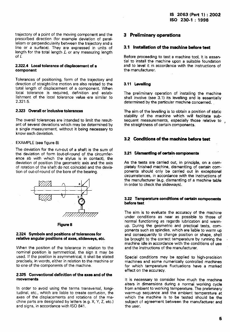
The overall tolerances are intended to limit the result-ant of several deviations which may be determined bya single measurement, without it being necessary toknow each deviation.
EXAMPLE (see figure 8)
The deviation for the run-out of a shaft is the sum ofthe. deviation of form (out-of-round of the circumfer-ence ab with which the stylus is in contact), thedeviation of position (the geometric axis and the axisof rotation of the shaft do not coincide) and the devia-tion of out-of-round of the bore of the bearing.
n af
1< , v]
u b
///////////////
Figure 8
2.324 Symbols and positions of tolerances forrelative angular positions of axas, slideways, etc.
I
I
I
When the position of the tolerance in relation to thenominal position is symmetrical, the sign * may beused. If the position is asymmetrical, it shall be statedprecisely, in words, either in relation to the machine orto one of the components of the machine.
2.325 Conventional definition of the axes and of themovements
In order to avoid using the terms transversal, longi-tudinal, etc., which are liable to create confusion, theaxes of the displacements and rotations of the ma-chine parts are designated by letters (e.g. X, Y, Z, etc.)and signs, in accordance with ISO 841.
3 Preliminary operations
3.1 Installation of the machine before test
Before proceeding to test a machine tool, it is essen-tial to install the machine upon a suitable foundationand to level it in accordance with the instructions ofthe manufacturer.
3.11 Levelling
The preliminary operation of installing the machineshall involve (see 3.1 ) its Ievelling and is essentiallydetermined by the particular machine concerned.
The aim of the Ievelling is to obtain a position of staticstability of the machine which will facilitate sub-sequent measurements, especially those relative to ~the straightness of certain components.
3.2 Condtiions of the machine before test
3.21 Dismantling of oartain components
As the tests are carried out, in principle, on a comp-letely finished machine, dismantling of certain com-ponents should only be cartied out in exceptionalcircumstances, in accordance with the instructions ofthe manufacturer (e.g. dismantling of a machine tablein order to check the sideways).
3.22 Temperature condkions of certain componentsbefore test
The aim is to evaluate the accuracy of the machineunder conditions as near as possible to those ofnormal functioning as regards lubrication and warm-up. “During the geometric and practical tests, com-ponents such as spindles, which are liable to warm upand consequently to change position or shape, shallbe brought to the correct temperature by running themachine idle in accordance with the conditions of useand the instructions of the manufacturer.
Special conditions may be applied to high-precisionmachines and some numerically controlled machinesfor which temperature fluctuations have a markedeffect on the accuracy.
It is necessary to consider how. much the machinealters in dimensions during a normal working cyclefrom ambient to working temperature. The preliminarywarm-up sequence and the ambient temperature atwhich the machine is to be tested should be thesubject of agreement between the manufacturer andthe user.
5

IS 2063 (Part 1) :2002
ISO 230-1 :1996
I
1
I
The main areas where thermal distortion can causeconcern are:
a) the structure (including spindle) displacement,especially in the prima~ and axial planes;
b) the axis d~ives and positioning feedback systemswhich are important when the positioning accu-racy depends on the lead screw.
3.23 Functioning and loading
Geometric tests shall be made either when the ma-chine is at a standstill or when it is running idle. Whenthe manufacturer specifies it, for example as in thecase of heavyduty machines, the machine shall beloaded with one or more test pieces.
4 Machining tests
4.1 Testing
Machining tests shall be carried out on standard testpieces or test pieces supplied by the user. The ex-ecution of these machining tests shall not requireoperations other than those for which the machinehas been built. Machining tests shall comprise thefinishing operations for which the machine has beendesigned.
The number of workplaces or, as the case may be,the number of cuts to be made on a given workpiece,shall be such as to make it possible to determine thenominal accuracy. If necessary, wear on the cuttingtool used should be taken into account.
The nature of workplaces to be made, their material,their dimensions and the degree of accuracy to beobtained, and the cutting conditions shall be agreedbetween the manufacturer and the user, unless ISOspecifications already exist.
42 Checkingof workpiecasin machiningtests
Checking of workplaces in machining tests shall bedone by measuring instruments selected for the kindof measurement to be made and the degree of accu-racy required.
The tolerances indicated in 2.321, particularly in2.321.1 and 2.321.2, are to be used for these checks.
in certain cases, the machining tests may be replacedor supplemented by a special test defined in the
corresponding International Standard (e.g. deflectiontest under load, kinematic test, etc.).
5 Geometric tests
5.1 General
For each geometric test of a given characteristic ofshape, position or displacement of lines or surfaces ofthe machine such as:
—
—
—
—
—
straightness (see 5.2),
flatness (see 5.3),
parallelism, equidistance and coincidence (see5.4),
squareness (see 5.5),
rotation (see 5.6),
a definition), methods of measurement and the wayto determine the tolerance are given.
For each test at least one method of measurement isindicated, and only the principles and apparatus usedare shown.
When other methods of measurement are used, theiraccuracy shall be at least equal to the accuracy ofthose in this part of ISO 230.
Although, for the sake of simplicity, the methods ofmeasurement have been chosen systematically fromthose which employ only elementary measuring in-struments, such as straightedges, squares, mandrels,measuring cylinders, precision levels and dial gauges,it should be observed that other methods, notablythose using optical devices, are in fact generally usedin machine tool building and in inspection depart-ments. Testing of machine tool components of largedimensions often requires the use of special devicesfor convenience and speed.
5.2 Straightness
Geometric checks covering straightness are thefollowing:
— straightness of a line in a plane or in space, see5.21 ;
— straightness of components, see 5.22;
— straightness of motion, see 5.23.
——1) See also 2.1,
6

IS 2063 (Part l) :2002ISO 230-1 :1996
5.21 Straightness of a line in a plane or in space
5.211 Defkition
5.211.1 Straightness of a line in a plane(see figure 9)
A line located in a plane is deemed to be straight overa given length when all its points are contained be-tween two straight lines parallel to the general direc-tion of the line, whose relative distance is equal to thetolerance.
The general direction of the line or representative lineshall be defined so as to minimize the straightnessdeviation. It maybe conventionally defined either:
— by two points appropriately chosen near the endsof the line to be checked (in most cases partsclose to the ends can be neglected, as they mostoften present insignificant local defects)
or
— by a straight line computed from(e.g. the least squares method).
Figure 9
I
plotted points
5.211.2 Straightness of a line in space (see figure 10)
A line in space is deemed to be straight over a givenlength when each of its projections on two givenperpendicular planes parallel to the general directionof the line is straight (see 5.21 1.1).
eFigure 10
NOTE 3 The tolerance maybe different in each plane.
5.212 Methbds of measurement of straightness
There are two methods for the measurement ofstraightness, based on either:
— the measurement of length
or
— the measurement of angles.
The practical reference for straightness can be physi-cal (straightedge, taut-wire) or by comparison toreference lines given by a precision level, light beam,etc.
Recommended instruments:
a) for lengths below 1 600 mm: a precision level orphysical reference (for example a straightedge);
b) for lengths above 1600 mm: reference lines (aprecision level, optical device or possibly a taut-wire).
5212.1 Methods based on the measurement oflength
A practical reference artifact (straightness reference)shall be placed in a suitable position relative to the lineto be checked (see figure 11), to allow the use of asuitable measuring instrument,
The instrument provides deviation readings of thechecked line with respect to the reference ofstraightness; readings may be obtained at variouspoints (uniformly distributed or random) over theentire length of the checked line (selected pointspacing being independent of the instruments used).
It is recommended to position the straightness refer-ence in such a way that readings at both ends areapproximately similar. Readings are then directlyplotted using appropriate scales.
Results are processed by defining a representativeline (see 5.211.1 ). Corrected deviations correspond tothe values represented by Mm’ segments.
The deviation of straightness is defined as the dis-tance between two straight lines, parallel to therepresentative line, touching the upper and lowerextremes of deviation.
NOTE 4 When the slope of the representative line is high,the vertical magnification should be considered.
I I Straightnessreferenceal \m b
~ straightnessdeviation
Figure11
7

IS 2063 (Part l) :2002ISO 230-1 :1996
I
5.212.11 Straightedge method
5.212.111 Measurement in a vertical plane
The straightedge should be placed on two blocks,located, if po+ible, at the points corresponding to theminimum deflection due to gravity (for optimumsuppoti, see A.2).
The measurement shall be made by mov”hg along thestraightedge a dial gauge mounted on a support withthree contact points. One of these contact pointsrests on the line of the “surface to be measured andthe dial gauge stylus is on the line normal to thatcontact point and in contact with the straightedge(see figure 12).
m(Hh-l
Provision shall be made for the moving component tofollow a straight line (guiding straightedge).
Known errors of the straightedge can be taken intoaccount, if required, in processing the result.
5.212.112 Measurement in a horizontal plane
In this case it is advisable to use a parallel-facedstraightedge lying flat.
The reference face is touched by a dial gauge movingin contact with the surface to be checked (see fig-ure 13). The straightedge is set to give identical read-ings at both ends of the line; deviations in the linerelative to the straight line joining the two extremesmay be read off directly.
L ~ara,,e(b,ock,J s“l’face+olJedled(eci
Contactpointonline normalwith stylus
Figure 12
Reference
/--blocks-
00000000u u
face
Ir-l
[ r
Surfaceto be
////////22///.227/////;///////////Ist reading
Referenceface
n n0000 0000
I I I Iu/
u/
n1 I
checked
////////7)///))/////////////////7’2ndreading
Figure 13

.,.IS 2063 (Part 1) : ‘2002ISO 230-1:1996
I
It should be noted that whatever the straightedgedeflection on its supports, the reference-face straight-ness is in practice not altered by this deflection due togravity.
Another feature of the straightedge method for straight-ness measurement in a horizontal plane is that it allowsmeasurement of straightness deviations of both thestraightedge reference face and the surface to bechecked.
For this purpose the so-called reversal method isused. It consists, after a first measurement as de-scribed above, in rotating the straightedge 180° aboutits longitudinal axis and traversing the same referenceface in reverse with the same dial gauge, also re-versed and always resting on the surface to bechecked.
r- Straightnessdeviationof thesurface
I .4
1
21
readingE1
Curve M
I _ 2ndreadingEz
l.- Straightness deviation of the straightedge
Figure14
Both deviation curves El and E2 thus obtained andcompared in figure 14 are the sum of the straightedgeand surface deviations on the one hand, and the
difference between those deviations on the otherhand.
The average curve M is the deviation of the referenceface of the straightedge. Deviation ME1 (or ME2which is equal) is the straightness deviation of thechecked surface.
5.212.12 Ta@-wira and microscope method
A steel wire, with a diameter of about 0,1 mm, isstretched to be approximately parallel to the line to bechecked (see figure 15). For example, in the case of aline MN, located in a horizontal plane, with a micro-scope placed vertically and equipped with a horizontalmicrometric displacement device, it is possible to readthe deviation of the line to the taut-wire representingthe reference of measurement in the horizontal planeof measurement XY (see also A.9).
The taut-wire F and the line to be checked shall be inthe same plane perpendicular to the consideredsurface containing MN.
The microscope support rests on the surface contain-ing the line to be checked at two points, of which, onepoint P is situated in the plane normal to the surfaceconsidered, containing the microscope optical axis(see figure 15).
The taut-wire method is to be avoided when the sag ~of the wire F has to be taken into account. Thus, inthe case of figure 15 with a microscope placed hori-zontally, it is possible to measure the straightness ofline RS in a vertical plane when the sag of the wire isknown at each point, but this sag is extremely difficultto determine with adequate accuracy.
Y
32
RI
s
!
M N
Section according to X-Y plane
Figure 15
9

IS 2063 (Part 1) :2002ISO 230-1 :1996
5.212.13 Alignment telescope method
When using an alignment telescope (see figure 16),the difference in level, a, corresponding to the dis-tance between the optical axis of the telescope andthe mark shown on the target, is read directly on thereticle or by means of the optical micrometer (seeA.1O).
The optical axis of the telescope constitutes thereference of measurement.
By rotating the entire telescope and the target, it ispossible to check the straightness of a line in anyplane.
The target support should rest on the surface contain-ing the line to be checked at as many points as ra-quired to ensure stability and guidance.
One of the target support points P shall be placed onthe line to be checked and treated with all precautionsas described in 5.212.12.
The target shall be normal to the surface containingthe line to be checked at point P.
All precautions shall be taken for the moving elementdisplacement to be reasonably rectilinear and parallelto the telescope optical axis.
In the case of longer lengths, the accuracy is affected~ by the variation of the refractive index of air, which
\ contributes to the deviation of the light beam.
I
I
5.212.14 Alignment Iaaar technique (seefigure 17)
A laser beam is used as the reference of measure-ment. The beam is directed at a four-quadrant photo-diode detector which is moved along the axis of thelaser beam. Horizontal and vertical deviations of thedetector centre with respect to the beam are de-tected and passed to recording equipment. Themeasuring instrument manufacturer’s instructionsshould be consulted (see also A.1 3).
Equal care shall be taken with one of the detectorsupport points P as described in 5.212.13.
5.212.15 Laaar interfaromatry technique (seefigure 18)
The hi-mirror reflector defines the reference ofmeasurement.
A laser interferometer and special optical componentsare used to detect changes in the position of a targetrelative to the axis of symmetry of the bkmirror reflec-tor. The optical components and precise measuringmethods vary and manufacturers’ instructions shouldbe consulted (see also A.1 3).
Equal care shall be taken with one of the detectorsupport points P as described in 5.212.13.
Figure16
6-quadrant photodiode7
Bi-mirror reflectorWollaston prisminterferometer
E Ld
Laser .— - —.— .— .— .— .—
A’ A
Figure 17 Figure 18

IS 2063 (Part l) :2002ISO 230-1 :1996
5.212.2 Methods based on the measurement ofangles
In these methods a moving element is in contact withthe line to be checked at two points P and Q separ-ated by a distance d (see figure 19). The movingelement is displaced in such a way that in two suc-cessive positions POQO and PIQ1, PI is coincidentwith Qo. W/th an instrument placed in a plane per-pendicular to the surface containing the line to bechecked, the angles q and al of the moving elementrelative to a reference of measurement are measured.
NOTE 5 The part between the feet of moving elements isnot checked by this method. This check can be carried outby a straightedge of appropriate length.
~_-__,
—.
Reference of measurement ---J’
Figure19
Results are processed as follows (see figure 20). Thefollowing parameters are plotted graphically withappropriate scales:
— in abscissae, the feet distances d corresponding<1 to the checking line,\
1 — in ordinates, the relative differences of level withrespect to the reference of measurement. The
\ relative level difference is calculated as follows:\
I Ehi+l =dtan ai
The various points Po, PI, P2 ... Pi ... Pn of thechecked line can be located with the desired scalemagnification.
The representative line is defined from the line itself,e.g. by the extremes P. Pn (see 5.21 1.1).
The straightness deviation is defined as above(5.21 2.1 ) by the distance along the YY axis betweentwo. straight lines parallel to the representative linetouching the curve at its higher and lower points.
NOTES
6 The supports P and Q of the moving element should beof sufficient area to minimize the effect of minor surfaceimperfections. It is necessa~ to prepare the supports verycarefully and clean the surface in order to minimize devi-ations which can influence the overall curve.
7 These methods can also be applied over long distancesbut in this case the d value should be chosen so that alarge number of readings and cumulative errors can beavoided.
5.212.21 Preciion level ,method
The measurement instrument is a precision level (seeA.6) which is positioned successively along the line tobe checked as explained in !5.212.2. The reference ofmeasurement is the horizontal level of the instrumentwhich measures small angles in the vertical plane (seefigure 19).
If the line to be measured is not horizontal, the level ismounted on a suitably angled support block (seefigure 21).
‘-l+Y Representative line .-
Pf)~~ \ 1Reference of measurement
Figure 20
r Guiding straightedge
A
Figure 21
11

IS 2063 (Part 1) :2002
ISO 230-1 :1996
While checking line AB, the level togethersuPPort should keep a constant orientation
with its[e.g. by
means of a guiding straightedge (see figure 21)1.
NOTE 8 The level permits, checking the straightness onlyin the vertical plane; for the checking of a line in a secondplane another method should be used (e.g. taut-wire andmicroscope).
5.212.22 Autocollimation method
In this method, using an autocollimator mountedcoaxially (see figure 22), any rotation of the movablemirror M around a horizontal axis entails a verticaldisplacement of the image of the reticle in the focalplane. The measurement of this displacement, whichis made with the ocular micrometer, permits theangular deviation of the mirror holder to be deter-mined (see also A.11 ).
The measuring reference is composed of the opticalaxis of the telescope as defined by the cerme of thereticle.
NOTES
9 By rotating the ocular micrometer through 90°, therotation angle of the movable mirror M around a vertical
8
axis can also be measured. Instruments which are capableof measuring both angles simultaneously are available.
10 This method is especially suited to longer lengthsbecause, in contrast to the alignment telescope, it is tessinfluenced by variations in the index of refraction of air dueto the double course of the light beam.
11 In this method, the autocollimator should preferably bemounted on the chmponent on which the line is to bechecked.
5.212.23 Method by Iasck interferometer (anglemeasurement) (see figure 23)
In this method the interferometer should be rigidlyfixed to the same component on which the line is tobe checked.
This method is especially suited to critical measure-ments” because it is less influenced by variations inthe index of refraction of the air.
The reference of measurement is constituted by twoparallel beams F1 and F2 issuing from the interfer-ometer.
Movable mirror
M.
Autocollimator
Figure22
r Laser sourcef-
Interferometer/-
Moving element
1 FI
F2
\\\\\ss\\\\\\\\\
P-=-?
Figure23

5.213 Tolerance
5.213.1 Definition
The tolerance t is limited in the measuring plane bytwo straight lines separated by distance tand parallelto the representative line AB (see figure 24). Themaximum deviation indicated is MN.
The range of measurement, i.e. he length to bechecked, and possibly the position of the tolerance Inrelation to the representative straight line (or plane)defined above, should be stated (concave or convexonly).
In most cases, parts close to the ends, which usuallyhave local deviations of no great importance, may beneglected.
I N
M
Figure24
5.213.2 Determination of tolerance
A minimum tolerance TI is specified for any measur-ing length L smaller than or equal to JLl (see figure 25):
A maximum tolerance T2 is specified for any measur-ing length L greater than or equal to Lz.
For any intermediate measuring length (between LIand L2) the tolerance T(L) is calculated by a pro-portional method:
LGL1 -+ T(L) = T1
L~<L<L2 + T(L) = T1 + ‘2-T (L- L,)~-L1
L>L2 --) T(L]=T2
I
IS 2063 (Part 1) :2002ISO 230-1 :1996
5.22 Straightness of components
5.221 Definition
The conditions for the straightness of a componentare the same as those for a line (see 5.21 1).
5.222 Methods of straightness meesuremant
Measurement techniques are as for straightness of aline (see 5.21 2).
5.222.1 Reference grooves or reference surface ofteblas
In the case of a direct deviation measurement, theinstrument shall read deviations in the normal plane ofthe line through the points P or Q with h kept to aminimum (see figure 26).
Figure 26
In the case of angular deviation measurements, thedistance d defines the measuring-point spacing (seefigure 27).
The moving element shall lie flat on the table (restingpreferably on three localized surfaces S1, S2, S3) andinclude two functional bearing surfaces P and Q onthe line to be checked (see figure 27).
L, L2
Measuring length, L
Figure25 Figura 27
13

IS 2063 (Part 1 ) :2002ISO 230-1 :1996
I
\
I
Straightness deviations of more complex referencesurfaces (see figure 28) are measured in the func-tional planes of the slideway (lines Htl and W) andnot square to the reference plane.
li_G27-””-””-””-””1
\ I
\
1“
Figure 28
5.222.2 Slidaways
Guiding is ensured by slideways or by more complexdevices which cannot be dismantled without destroy-ing the machine geometry. The checking of slidewaysinvolves the measurement of straightness and shouldonly be carried out if the component is accessible.More complex slideways must be checked as part ofthe measurement of the straight-line motion of themoving component (see 5.23).
The deviation of straightness should always bechecked in the functional plane. Generatty, this can beregarded as either horizontal (figure 29 line AA) orvertical (figure 29 line BB) although exceptions mayoccur with certain machine configurations (see fig-ure 36).
It must be noted that the longitudinal shape of a.sIideway is not necessarily straight, as it may presentin the functional plane a special form specified by themanufacturer.
The guiding swfaces may be composed of the follow-ing
a)
b)
one plane or several small sections joinedtogether;
several narrow plane sections, cylindrical slide-ways or an assembly of the ttio.
B
II
1
Figure 28
5.222.21 Vaa surfaces
The ~~vinq body should bear on the surfaces at fourcontact” points. It shall also be supported by an ad-
14
ditional point on a different surface of the slideway forstability.
Figures 30 and 31 show the use of a recessed cylin-der, and figure 29 an inverted recessed vee.
NOTE 12 The additional support point should not exert apositioning force on the moving component.
Figure 30
‘-h
Hgure 31
5.222.22 Cylindrical surfaces
The moving body on four pads should rest on thecylinder. This is in the form of an inverted vee (seefigures 32 and 33).
The same precaution shall be taken as above regard-ing the additional support of the block.
L-- Additional support point
Figure 32
P-
~ Additional SUppOM pOht
Figure 33

IS 2063 (Pwtl ):2002ISO 230-1 :1996
{
I
“>
I\
I
I1
5.222.23 single vertical surfaces 5222.3 Tolerances
The moving body makes contact by two points, P andQ on the surface to be measured. Three additionalsupport points are required to guide the moving body.These should be chosen to ensure guiding withoutinfluencing the positioning of the two operationalcontact points (see figures 34 and 35).
NOTE 13 When the deviations a;G being measured di-rectly, the instrument should take measurements on ‘theplane normal to the surface and through one of the contactpoints, and when measuring angular deviations, the dis-tance d defines the measurement pitch.
.-
Reference plane -J
See 5.213.
523 Straight-line motion
Tests for the straight-line motion of a component of amachine tool are required not only to ensure that themachine will produce a straight or a flat workpiece butalso because the position accuracy of a point on theworkpiece is related to the straight-line motion.
5231 DefMtions (see figure 37)
The straight-fine motion of a moving componentalways involves six elements of deviation:
a) one positional deviation in the direction of motion;
b) two linear deviations of the trajectory of a point onthe moving component;
Figure 34 c) three angular deviations of a moving component.
P- Y
Figure 35
5.222.24 Slant-bed configuration (see figure 36)
“In this case, the functional plane of the moving el-ement is at an angle to the horizontal plane.
The deviation of straightness is measured in this func-tional plane (line AB) and a plane that is normal to it.
EBZ&
x-Deviation by Z-direction motion
IXZ Linear deviation E/&% PitchEYZ Linear deviation EBZ Yaw 1 Angular
EZZ: Positional deviation ECZ: Roll 1deviation
Flguf’a 37
5231,1 Positional deviations
Positional deviations are dealt with in 2.322.1 andISO 230-2.
Functional plane 52312 Unear deviations
Linear deviation of straight-line motion is defined bythe straightness of the trajectory of the functionalpoint or the representatiyq point of a moving com-ponent. The functional point is the position of the toolwhen a moving component carries the tool. When amoving component carries the workpiece, the centreof the table may be regarded as the representative
Figure 36 point.
15

IS 2063 (Part 1 ) :2002ISO 230-1 :1996
5.231.3 Angular deviations
Whenever a component is moved, it is involved inangular deviations. These angular deviations are calledroll, pitch and yaw, as shown in figure 37.
All of these dcJviations will affect straight-line motion,.When measuring the straight-line motion of the trajec-tory of a representative point, the measured resultsinclude all of the effects of angular deviations, but theeffects of these angular deviations are different whenthe position of a point of the moving component isdifferent from the representative point, and a separatemeasurement must be made. The value of eachangular deviation is the maximum angle turnedthrough during a complete traverse of the movingcomponent.
5.232 Methods of measurement
5.232.13 Mathod using an aiignment telescope (see5.212.13)
\Alhen using an alignment telescope, the reticle isconnected to the reference line, the target is connec-ted to the tool post and its centre is situated as nearto the active zone of the tool as possible (see A.1 O).
5.232.14 Method using a iasar (see 5.212.14 and5.212.1 5)
When using a laser (direct measurement using astraightness interferometer), the devices defining themeasuring reference must be firmly fixed to thecomponent chosen as reference. The moving elementis fixed to the tool holder and its centre is situated asnear as possible to the active zone of the tool (seeA.13).
5.232.15 Method using angie measurements (see5.212.2 and 5.232.2)
5.232.1 Methods of measurement of iinearThis method is not recommended for the checking oflinear deviations. For checking slideway straightness,
deviations the moving element has two feet, P and Q which are
To plot the trajectory of a functional point of a movingd apart (see figure 19) and the .slideway is checkedsuccessively in increments of d.
component, the follcwing methods are used.In this case, the moving component, in general, hasno such feet and contacts the surface over its full,
1 5.232.11 Method with a straightedge and a diai length.
Igauge (see5.212.1 12) - -
The results obtained mav be somewhat different from
i When using a straightedge and a dial gauge, it is usual the true trajectory. Assuming the surface is smooth$\ to fix the straightedge to the component used as a
and the moving component moves as the envelope of
‘> reference (work tables of milling machines, machining the surface, linear deviation can be assumed by the
centres, grinding machines, the bed of a lathe, etc.).process shown in figure 38.
\I The dial gauge is connected to the tool location point
with its stylus situated as near as possible to theAt the ith measuring point, the angular deviation is Oi.
I active zone of the tool (see A.2 and A.7).Assume @iis effective from the midpoint of i – 1 and ito i and i + 1. When an atmarent charme in 6 occurs,the distance of measurem~nt shall be changed there. ”I
1 5.232.72 Method w“tihmicroscopeandtaut-wire 5.232.2 Methods of measurement of anguiar\ (see 5.212 12) deviation
I This is the same situation as a straightedge and dial When the movement is in a horizontal plane, a pre-
1gauge, with the taut-wire representing the straight- cision level can measure the pitch and roll, whereasedge and the microscope representing the dial gauge an autocollimator and laser can measure the pitch and
I (see A.9). yaw.
— Linear deviation
Points of measurement
b 6 7I f)y .—-—
2 —3—-—.—_. _.\
Figure38

IS 2063 (Pmtl ):2002ISO 230-1 :1996
5.232.21 Method using aprecision level (see5.212.2)
When usinga precision level, the instrument is fixedto the moving component. The component is movedincrementally and the level readings are recordedafter each move.
5.232.22 Method using an autocollimator (see5.212.22)
When using an autocollimator, the mirror is mountedon the moving component and the autocollimator onthe reference line.
5.232.23 Method using a laser (see 5.212.23)
When using a laser, the remote interferometer andbeam bender can be fixed on the reference line andthe laser reflectors mounted on the moving com-ponent or vice versa.
..5.233 Tolerance
5.233.1 Tolerance for the linear deviation of straight-Iine motion
Tolerance defines the permissible deviation of thestraight-line motion of the trajectory of a functional .orrepresentative point in relation to the representativeline (general direction of the trajectory); the tolerancesof the two linear deviations may be different.I
\5.233.2 Tolerance for the angular deviation of
istraight-line motion
\ Tolerance defines the permissible angular deviation of$the straight-line motion of the component.
I,
Tolerance of angular deviation may be different for thethree components of pitch, roll and yaw.
j 5.3 Flatness
\.7 5.31 Definition\\
A surface is deemed to be flat within a given range of
\measurement when all the points are containedwithin two planes parallel to the general direction ofthe plane and separated by a given value.I
I The general direction of the plane or representative! plane is defined so as to minimize the flatness devi-
ation, i.e., conventionally, either:
—
or
—
by three points conveniently chosen in the planeto be tested (usually the part very near to theedge, having minor local defects, can be dis-regarded)
on a plane calculated from the plotted points bythe least squares method.
5.32 Methods of measurement
5.321 Measurement of flatness by meansof asurfaceplate
In measurement by means of a surface plate, theplate is covered by jeweller’s rouge or by chromiumoxide diluted in light oil. The surface plate covered inthis way is laid upon the surface to be measured. Aslight to-and-fro motion is applied. The plate is, re-moved and the distribution of the contact points persurface unit is noted. This distribution should beuniform over the whole area of the surface and shouldbe equal to a given value. The method is applied onlyto smaller-sized surfaces which present a relativelyfine finish (scraped or ground surfaces).
5.321.1 Measurement by means of a surface plateand a dial gauge
The measuring equipment consists of a surface plateand a dial gauge held in a support with a ground basewhich moves on the surface plate.
There are two measuring configurations:
a) the component to be measured is placed on thesurface plate (the dimensions of the surface plateand the shape of the dial gauge support must belarge enough to enable ~11-measured) (see figure 39).
Flatness to be measured
/
the surface to be
&Surface plate (Reference of measurement)
Figure39
b) the surface plate is placed facing the surface to bemeasured. In this case, testing is possible with asurface plate whose dimensions are similar to thatof the surface to be measured (see figure 40).
Flatness to be measured —
~Surface plate (Reference of measurement)
Figure40
17

IS 2063 (Part l) :2002
ISO 230-1 :1996
1,,
A pattern of squares is established to determine thelocations of the measuring points.
False readings due to surface defects maybe avoidedby:
a) using a dial gauge with a slightly rounded styluswhich is not affected by roughness;
b) placing a small ground block with parallel facesbetween the surface to be measured and thestylus of the dial gauge to absorb the surface de-fects (scraped surfaces, planed surfaces, etc.).
NOTE 14 In the first arrangement (figure 39) the positionof the dial gauge is influenced by the variation in the slopeon the surface of the surface plate. This method should bereserved for highly accurate surface plates. It is not poss-ible to take into account the defects of the surface plate;this method is reserved for small parts.
In the second arrangement (figure 40), where measure-ment is carried out by a dial gauge holder set perpen-dicularly to the surface plate, it is possible to take intoaccount the defects of the surface plate while processingthe results.
5.322 Measurementof flatnessby meansofstraightedge(s)
5.322.1 Measurement by means of a family of$treight !ines by d~lacament of a straightedge
The theoretical plane on which the reference pointswill be located is first determined. For this purpose,three points, a, b and c, on the surface to be testedare selected as zero marks (see figure 41 ). Threegauge blocks of equal thickness are then placed onthese three points, so that the upper surfaces of theblocks define the reference plane to which the sur-face is compared.
(o)
?’~(o)
a—.— .—. —
t+, “--.;:+’:+
*
<“ ‘\.—.— .—. —
+c
(0)
Figure41
A fourth point d lying in the reference plane is thenselected in the following manner: using gauge blockswhich are adjustable for h~;ght, a straightedge isplaced on a and c and an adjustable block is set at apoint e on the surface and brought into contact withthe lower surface of the straightedge. The uppersurfaces of the b!acks a, b, c, e are therefore all in thesame r)lane.
The deviation of point d is then found by placing thestraightedge on points b and e; an adjustable block isplaced at point d and its upper face brought into theplane defined by the upper surfaces of the blocksalready in position.
By placing the straightedge on a and d and then on band c, the deviations of all the intermediate points onthe surface lying between a and d and between b andc may be found. The deviations of the points lyingbetween a and b, c and d may be found in the sameway. (Any necessary allowance for sag in the straight-edge should be made.)
To obtain readings inside the rectangle or square thusdefined, it will only be necessa~ to place at points fand g, for example, the deviations of which will thenbe known, gauge blocks adjusted to the correctheight. The straightedge is placed on these, and withthe aid of the gauge blocks, the deviation betweenthe surface and the straightedge can be measured. Itis possible to use an instrument for the measurementof straightness, as shown for example in figure 12.
5.322.2 Measurement by ,maansof straightedges,aprecisionleveland a dialgauge(seefigure 42)
In this method the reference of measurement isprovided by two straightedges which are placedparallel by means of a precision level (see A.6).
Two straightedges RI and R2, mounted on rests a, b,c, d of which three are the same height and one isadjustable, are set up so that their upper rectilinearsurfaces are parallel by using a precision level. Thetwo straight lines RI and R2 are thus coplanar. Onereference straightedge R placed on R1 and R2 on topof any line fg of the square pattern enables the devi-ations to be read by means of a reading instrument G(or by means of standard gauge blocks).
The straightedges RI and R2 shall be sufficiently rigidso that the deflection due to the weight of the refer-ence straightedge is negligible.
Figure42
A reference of measurement is established anddeviations from the reference of measurement aremeasured and plotted. Plotting may be carried out atdifferent points following a regular pattern of squares,
?$
.

IS 2063 (Part l) :2002
ISO 230-1 :1996
\
see figure 43, covering all the surface of the plane tobe measured. The choice for spacing the points isindependent of the instruments used.
~ Representative plane
L vReference of measurement
Figure 43
5,323 Measurement of flatnessby meansof aprecisionlevel
This is the only method known at present whichenables a constant direction of measuring reference(horizontal) to be maintained while the instrument ismoved from position to position.
Straightness measurement of a line using the angulardeviation method (5.21 2.2) is the basis of thismeasurement.
5.323.1 Measurement of a rectangular surface
The reference plane is determined by two straightlines OmX and 00’Y, where O, m and O’ are threepoints on the surface to be checked (see figure 44).
d d
o m’ m“ A _x
o’ A’
o“ A“
c BM M’ M“
Figura44
The lines OX and OY are chosen preferably ‘at rightangles and if possible parallel to the sides outliningthe surface to be measured. Measurement begins inone of the corners O of the surface and in the direc-
tion OX. The profile for each line OA and OC is deter-mined by the method indicated in 5.212.21. Theprofile of the longitudinal lines O’A’, @ A“ and CB isdetermined so as to cover the whole surface.
Supplementary measurements may be made follow-ing mM, m’M’i etc., to confirm the previous measure-ments.
When the width of the surface to be measured is notdisproportionate to its length, it is desirable, as across-check, also to take measurements along diag-onals.
Interpretationof measuredresults(seefigures 45and 46).
From the results of measuring lines Omm’A and00’O”C, using the process shown in figure 20, drawa topographical plotting of Omm’A and 00’O”C. Forplotting of lines O’A’, O“A” and CB the starting pointsshall be O’, O“ and C. In the case of figure 45, all theplottings are very ne~r to the measuring referenceand this plane may be said to be a representativeplane, but in the case of figure 46 representative linesof Omm’A and 00’O”C are in the directions OX’ andOY’. In such a case, the representative plane willprobably be the plane containing OX’ and OY’, i.e.plane OABC.
z m“”
~m’
m
z
Figure45
x“
A
z
z .Y
Figure 46
5.323.2 Measurement of plane surfaces with circularcontours
Large plane surfaces which have circular contours donot lend themselves to an orthogonal square pattern,
19

IS 2063 (Part l) :2002ISO 230-1 :1996
1
which leaves certain parts unchecked. Therefore, it ispreferable to carry out the survey using peripheralcircles and diameters (see figure 47).
.
NOTE 15 For small surfaces, flatness measurements arecarried out in a simplified way by measuring the straight-ness:
—
—
of two perpendicular diameters;
of the sides of the square joining extreme points (seefigure 48).
@
Figure48
a)
b)
Circular verification
A r)recision level is placed on an isostatic supportA and moved at regular intervals around the per-iphery of the plate.
Diametrical verification
This is carried out using any method of measuringthe straightness of a line (see 5.21).
5.324 Measurement of flatness by optical methods
5.324.1 Measurement by an autocollimator
Straight lines OX and OY defining the reference planeare determined by the optical axis of the autocol-Iimator in two positions and, if possible, at 90° to eachother. The method given in 5.212.22 is then followed.
The reference plane of measurement is determinedby the directions of the optical axes of the autocol-Iimator OX and OY. Thus, for the measurements ofO’A’, OA” and CB, the optical axis of the autocol-Iimator shall be parallel to OX (see figure 44).
5.324.2 Measurement by a sweep optical square
Alternatively, a sweep optical square (pentagonalprism) is used. The reference plane is established bythe centres of the three datum targets (A, B and C)placed at the periphery of the surface (see figure 4.9).The square is aligned so that the telescope opticalaxis is perpendicular to the reference plane and afourth target is used to measure the position of anypoint on the surface (see A.1 2).
Fourth target
Figure 49
20
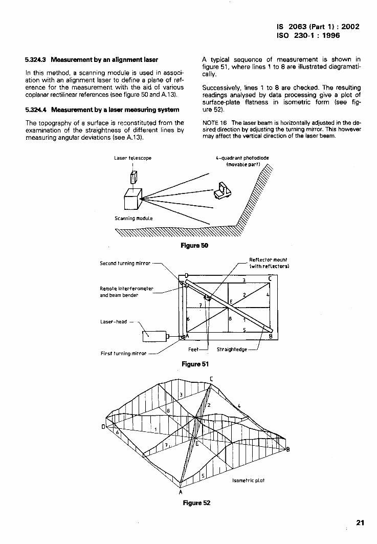
IS 2063 (Part 1) :2002ISO 230-1 :1996
.-
1
I
I
5.324.3 Measurement by an alignment laser
In this method, a scanning module is used in associ-ation with an alignment laser to define a plane of ref-erence for the measurement with the aid of variouscoplanar rectilinear references (see figure 50 and A.13).
5.324.4 Measurement by a laser measuring system
The topography of a surface is reconstituted from theexamination of the straightness of different lines bymeasuring angular deviations (see A.1 3).
A typical sequence of measurement is shown infigure 51, where lines 1 to 8 are illustrated diagrammat-ically.
Successively, lines 1 to 8 are checked. The resultingreadings analysed by data processing give a plot ofsurface-plate flatness in isometric form (see fig-ure 52).
NOTE 16 The laser beam is horizontally adjusted in the da-sired direction by adjusting the turning mirror. This howevermay affect the vertical direction of the laser beam.
Laser telescope 4-quadrant photodiode1 (movable part) ~
Scanning module
Figure50
Second turning mirrorReflector mount
~ (with reflectors)
Rean
La
First turning mirror --./ ‘eetd Str’’g’te’ged
Figure51
A
Figure 52
21

IS 2063 (Part 1) :2002ISO 230-1 :1996
,
I
5.325 Measurement by a coordinate measuringmachine
Surface flatness can be measured by a coordinatemeasuring machine (CMM). A reference plane may beestablished f om the CMM software according to 5.31
aland out-of-fl ness from this plane is determined (seefigure 43).
5.33 Tolerances
The tolerance zone of the flatness is limited by twoplanes, distant by t,parallel to the general direction ofthe plane (representative plane).
The range of measurement and the position of thetolerance in relation to the representative plane shouldbe specified.
Tolerances of flatness are itidicated as follows.
—
—
—
Tolerance of flatness: . . . mm when, between theends, concavities and convexities of surfaces areallowed.
Concave (or convex) to: . . . mm when, betweenthe ends, only concavities (or convexities) of sur-face are allowed.
Local tolerance: . . . mm for . . . mm x . . . mmwhen it is specified and both concavities and con-vexities are allowed.
Further tolerance in this case should be known as“local tolerance”.
NOTE 17 The results of the check may be affected by thecondition of the contact surface of the instrument stylus.When deemed necessary, the condition of this contactsurface may be specified.
5.4 !%Aielism, equidistance and coincidence
These measurements address the following features:
—
—
—
—
parallelism of lines and planes, see 5.41;
parallelism of motion, see 5.42;
equidistance, see 5.43;
coaxiality, coincidence or alignment, see 5.44.
5.41 Parallelism of lines and planes
5.411 Definitions
A line is deemed to be parallel to a plane if, whenmeasuring the distance of this line from the represen-tative line (see 5.211.1 ) of intersection of the planeand the, normal plane including the line at a number ofpoints. the maximum difference observed within agiven range does not exceed a predetermined value.
Two lines are deemed to be parallel when one ofthese lines is parallel to the two planes passingthrough the representative line of the other line. Thetolerances of parallelism are not necessarily identicalin the two planes.
Two planes are deemed to be parallel when themaximum range of distances from the representativeplane of one of these planes to the other plane,measured over the entire surface in at least twodirections, does not exceed an agreed value over aspecified length.
Maximum range means the difference between themaximum and the minimum dimensions obtainedwhen measuring.
These differences are measured in given planes(horizontal, vertical, perpendicular to the examinedsurface, crossing the examined axes, etc. ) within agiven length (e.g. on 300 mm or over the entire sur-face).
NOTE 18 Parallelism is defined as the difference ofdistance from the representative line (or plane) of a line (orplane) to another line or plane. If the line (or plane) selectedas reference is inverted, the result may be different.
5.412 Methods of measurement
5.412.1 General, for axes
Where measurement of parallelism involves axes, theaxes themselves shall be represented by cylindricalsurfaces of high precision of form, suits’ble” surfacefinish and sufficient length. If, the surface of thespindle does not fulfil these conditions, or if it is aninternal surface and will not admit a feeler, an auxiliarycylindrical surface (test mandrel) is used.
Fixing and centring of the test mandrel shall be doneon the end of the shaft or in the cylindrical or conicalbore designed to take the tool or other attachments.
When inserting a test mandrel on the spindle axis soas to represent an axis of rotation, allowance shall bemade for the fact that it is impossible to centre themandrel exactly on the axis of rotation. When thespindle is rotating, the axis of the mandrel describes ahyperboloid (or a conical surface, if the axis of themandrel intersects the axis of rotation) and gives twopositions B-B’ lying in the plane of test (see figure 53).
Figure53
22

IS 2063 (Part 1) :2002ISO 230-1 :1996
The measurement of parallelism may, under theseconditions, be effected at any angular orientation ofthe spindle, but should be repeated after rotating thespindle through 180°. The algebraic mean of the tworeadings gives the deviation of parallelism .in the givenplane.
The mandrel may also be brought into the meanposition A (termed ‘mean position of run-out’); themeasurement should then be effected in this positiononly.
The first method seems to be as quick as the second,and is more accurate.
NOTE 19 The term ‘mean position of ;un-out’ is to beunderstood as follows: a gauge stylus is brought intocontact, in the plane of test, with the cylindrical surfacerepresenting the axis of rotation. The reading of themeasuring instrument is observed as the spindle is slowlyrotated. The spindle is in the mean position of run-out whenthe pointer gives a mean reading between the two ends ofits stroke.
5.412.2 Parallelism of two planes
The following methods can be used to verify theparallelism of two planes. The measurements shouldbe carried out in two directions, preferably perpen-dicular to each other.
\ 5.412.21 Straightedge and dial gauga
I
\
The dial gauge, mounted on a support with a flat baseand guided by contact with the straightedge, is movedon one plane by the amount specified. The stylus
s slides along the second plane (see figure 54).!,1
!
(
I Guiding straightedge
Ii
..\
1 ~Reference plane
1 Figure54
I1 .5;412.22 Precision level method
The level is supported on a carrier which bridges thetwo planes to be compared. A succession of readingsis taken along the planes, and then the maximumdifference of reading (angle) gives the angular paral-lelism deviation and the reading (angle) multiplied by 1gives the linear parallelism deviation (see figure 55and A.6).
If it is difficult to bridge the two planes, the carrier isnot used and readings are taken along each plane withthe horizontal used as, the measuring reference(5.21 2.2). Comparison of the readings at correspond-ing positions indicates parallelism.
Guide b~ock Carrier
t- -1
Figure55
5.412.3 Parallelism of two axes
The measurement is made in two planes:
— in a plane passing through two axesz);
— then in a second plane perpendicular, if possible,to the first.
5.412.31 Plane passing through two axes2J
The measuring instrument is held on a support with abase of suitable shape, so that it slides along a cylin-der representing one of the two axes; the stylusslides along the cylinder retxesenting the second axis.
To determine the minimum reading between the axesat any point, the instrument shall be gently rocked in adirection perpendicular to the axes (see figure 56). Ifnecessary, the deflection of the cylinder under theweight it will have to supPort during measurementmay be taken into consideration.
$,x--- -%
o/
Figure56
5.412.32 Second plane perpendicular to the first
This measurement method requires an additionalplane, if possible paral!el to that passing through thetwo axes.
2) This expression means a plane passing through one of the two axes and as near as possible to the second axis.
23

IS 2063 (Part l) :2002ISO 230-1 :1996
If this additional plane exists, by virtue of the fact thatthe two axes are parallel to a surface of the machine,the parallelism of each axis, considered separately,shall be determined in relation to this surface in themanner described in 5.412.4. If not, the measurement
Yshould be ma e with reference to a theoretical planeby means of a level with an adjustable glass tube. Forthis purpose, the latter should be placed on the twocylinders representing the axes, and the air-bubble setto zero. If the two axes are not in the same horizontalplane, an auxiliary block, fixed or adjustable, may beused (see figures 57 and 58).
Figure57 Figure56
The level is moved along the axes by the amountspecified, and readings taken. The measurement isexpressed in terms of the distance between the axes.If, for example, this distance is 300 mm and the levelreading is 0,06 mm/l 000 mm, the deviation of paral-lelism will be 0,06 x0,3 = 0,018 mm.
5.412.4 Parallelismof an axisto a plane
I
I
The measu~ing instrument is held on a support with aflat base and moved along the plane by the specifiedamount. The stylus will slide along the cylinder rep-resenting the axis (see figure 59).
I
///////////////// ////
---1
Figure59
At each, point of measurement, the minimum readingis found by slightly moving the measuring instrumentin a direction perpendicular to the axis.
24
In the case of a pivoting axis, measurement in themean position and the two extreme positions will besufficient (see figure 60).
NOTE 20 For the deviation of parallelism of the represen-tative cylinder from the axis, see 5.412.1.
.— .—
///////////////////// ////
Figure60
5.412.5 Parallelism of an axis to the ‘mtersaction oftwo planes
The measuring instrument is held on a support with abase of suitable shape resting on the two planes. Theinstrument is then moved the specified distance alongthe straight line of intersection, and the stylus willslide along the cylinder representing the axis (seefigure 61). The measurement shall, as far as possible,be made in two perpendicular planes chosen as beingof greatest importance in the operation of the ma-chine tool.
NOTE 21 For the deviation of parallelism of the represen-tative cylinder from the axis, see 5.412.1.
--l
5.—.—.0/
Figure61
5.412.6 Parallelism of the intersection of two planesto a third plane
Where the intersection and the third plane are con-veniently situated to one another, a mounting blockand precision level are used (see figure 62). The

IS 2063 (Part 1) :2002ISO 230-1 :1996
.-
assembly is moved along the intersection, andchanges in the angular readings multiplied by f rep-resent deviations of parallelism (see 5.41 2.32).
Precision level7
L--J-4Figure62
If the third plane is not conveniently situated, amounting block and dial gauge are used (see fig-ure 63). The stylus is positioned at right angles to thethird plane and a succession of readings is takenalong the line of the intersection.
For other measurement procedures, see 5.412.2.
The included angle between the location faces of themounting block shall be accurately matched to theintersection angle of the two planes. This can beverified with a marking agent such as jeweller’s
, rouge.
1 -Pi(3
1 Figure63
\5.412.7 Parallelism between two straight lines, each
I formed by the intersection of two planesI
This measurement may be carried out as in 5.412.5.The stylus of the measuring instrument bears on avee-block which will slide along the planes forming
I the second intersection. The measurement shall beI made in two planes perpendicular to one another (see, figure 64).
This method requires very rigid mounting of themeasuring instrument, a condition which can beobserved only in the case of two straight lines closeto each other. As a rule, a level should be used, atleast for the measurement of parallelism in a verticalplane (see figure 65).
NOTE 22 If a direct measurement of the planes or straightlines concerned is difficult because of interference by com-ponents of the machine tool within the field of measure-ment, the measurement may be related to a referenceplane constituted by, for example, a horizontal plane deter-mined by a precision level.
Figure65
5.413 Tolwences
Tolerance of parallelism of straight lines or planesurfaces is given as follows:
tolerance of parallelism: . . . mm.
If the parallelism is to be measured only for a givenlength, this length shall be indicated, e.g.:
0,02 mm for any measuring length of 300 mm.
As a rule, the direction of- the deviation is not im-portant; however, if the deviation of parallelism is tobe allowed only in one direction, the direction shall beindicated, e.g.:
free end of the spindle in an upward direction only(relative to the table surface).
It should be remembered that the tolerance on paral-lelism includes the tolerance of form of correspondinglines and <irfaces, and the results of a measurementdepend on the stylus surface which should, whenrequired, be stated.
5.42 Parallelismof motion
5.421 Definition
The term ‘parallelism of motion’ refers to the positionof the trajectory of the functional point (see 5.231.2)of a moving part of the machine in relation to:
— a plane (support or slideway);
— a straight line (axis, intersection of planes);
— a trajectory of a point on another moving com-~onent of the machine.Figure64
25

IS 2063 (Part 1) :2002ISO 230-1 :1996
5.422 Methods of measurement ~lh i-l1(++ /.--.;,
5.422.1 General
Methods of’ measurement are usually identical withthose used for the measurements of parallelism oflines and planes.
The moving component shall, as far as possible, bedriven in the usual way, so as to allow for the effectof clearance and defects in slideways.
5.422.2 Parallelismbetweena trajectoryand a plane Figure67
5.422.21 Plane is on the moving component “tilf
.The dial gauge is attached to a fixed component of themachine, and the stylus bears at right angles to thesurface to be measured. The moving componentshould be moved by the amount stated (seefigu”re 66).
This type of measurement is typically applied onmilling and grinding machines where the workpiece ismounted on a worktable.
The dial gauge ts mounted in the spindle nose, asshown in figure 66, and the table traversed. Theresulting readings will reflect the accuracy (withrespect to parallelism) to be expected in the finishedworkpiece.
Figure66 Figure69
5.422.3 Parallelismof a trajectoryto an axis
The measuring instrument is fixed to the movingcomponent and is moved with it by the statedamount. The stylus slides over the cylinder or mandrelrepresenting the axis (see figure 70).
Slip(optional)
4-
Where there is a rotating axis, the mean positionshould-be used (see 5.412.1 ).
Machine tableUnless all planes are of equal importance, themeasurement shall be made, if possible, in two per-pendicular planes selected as being those mostimportant for the practical use of the machine.
Figure66
5.422.22 Planeis not on the moving component
1
E.—.—0/
The measuring instrument is attached to the movingcomponent and moved with it by the amount stated;the stylus is at right angles to the surface and slidesalong it (see figure 67).
If the stylus cannot bear directly on the surjace(e.g. the edge of a narrow groove), two alternativemethods may be used:
— use of angle lever attachments (see figure 68);
— use of a piece of suitable shape (see figure 69). Figure70
26
IS 2063 (Part 1) :2002ISO 230-1 :1996
5.422.4 Parallelism of a trajectory to the intersectionof two planes
Parallelism between each of the two planes and thetrajectory shall be measured separately, according to5.422.2. The position of the intersecting line is de-duced from the position of the planes.
5.422.5 Parallelism between two trajectdes
A dial gauge is attached to one of the moving com-ponents of the machine so that its stylus rests on agiven point on the other moving part. The two partsare moved together in the same direction by thesame amount as stated, and change in the readings ofthe measuring instrument is noted (see figure 71 ).
Unless all planes are of equal importance, this meas-urement shall be made in two perpendicular planesselected as being those of most importance in thepractical use of the machine.
..
II
I-.I
I
Figure71
5.423 Tolerance
Tolerance of parallelism of movement is the permiss-ible change in the shortest distance between thetrajectory of a given point on the moving part and aplane, a straight line or other trajectmy within a statedlength.
For the method of determining the tolerance, see5.413.
5.43 Equidistance
5.431 Definition
Equidistance relates to the distance between the axesand a reference plane. There is equidistance when theplane passing through the axes is parallel to thereference plane. The axes may be different axes orthe same axis occupying different positions afterpivoting.
5.432 Methods of measurement
5.432.1 General
The problem is identical with that of parallelism be-tween a plane passing through the axes and a refer-ence plane.
Tests for equidistance of two axes, or of a rotatingaxis, from a plane are, in effect, measurements ofparallelism (see 5.41 2.4). A test should first be madeto check that the two axes are parallel to the plane,and then that they are at the same distance from thisplane, by using the same dial gauge on the two cylin-ders representing the axes (see figure 72).
If these cylinders are not identical, the difference ofradius of the tested sections should be taken intoaccount.
—
Figure72
5.432.2 specialcaseof the equidistanceof two axesfrom the planeof pivotingof one of the axes
The plane of pivoting of the part carrying one of theaxes may not be accessible and may not allowmovement of the measuring instrument. It will then
. be necessary to construct an additional plane parallelto the plane of pivoting (see figure 73).
Auxiliary plane
Pivoting plane
~&g.—..—.—1- - p) -
.—.— Jl7////////////////////////////////// A
-4 .—
*Figure73
The setting and fixing of this auxiliary plane should becarried out so that, when a level is placed on it, ifpossible in two perpendicular directions, there is nodeviation during the pivoting motion of the com-ponent. The equidistance of the axis (in its middle aswell as in its extreme positions) is then tested, as wellas that of the fixed axis, in relation to the auxiliary”plane.
27

IS 2063 (Part 1 ) :2002ISO 230-1 : 1996
I
I
NOTE 23 When either a horizontal or oblique auxiiiaryplane is used, it is recommended that the dial gauge be setin its original place to ensure that no abnormal displace-ment has taken place when pivoting.
5.433 Tolerance
The permitted difference of distance should not bepreceded by a sign and shall be generally valid in alldirections parallel to the reference plane.
lf the difference is permissible in one direction only,the direction shall be specified, e.g.:
axis 1 higher than axis 2
5.44 Coaxiality, coincidence or alignments)
5.441 Definition
Two lines or two axes are said to be coaxial, coinci-dent or in alignment when their relative distance overa given length does not exceed a given value. Thedistance measured may be located either on theactual lines or on their extension.
5.442 Method of measurement
The measuring instrument is attached to an arm androtates through 360° about an axis. The stylus of themeasuring instrument passes in a given section Aover the cylinder representing the second axis (seefigure 74). Any variation in the readings representstwice the deviation of coaxiality. As the section
v A
H
I
Figure74
chosen for measuring may intersect both axes, thecheck shall be made in a second section B.
If the deviation is to be determined in two specifiedplanes (e.g. planes H and V in figure 74), the variationsfound in those two planes will be separately recorded.
It is necessary, particularly in the case of horizontalaxes, to have very. rigid mountings. When high accu-racy is required, two measuring instruments offset by180° shall be used simultaneously in order to elimin-ate the effect of deflection. Alternatively, a supportshall be used, the deflection of which is negligibleunder a weight double that of the dial gauge used.Dial gauges of very light weight shall be used in thesetests.
Since the direction of the measurement will varyduring rotation in relation to the direction of gravity,the sensitivity of the measuring instruments to theforce of gravity shall be taken into account.
When one of the two axes is an axis of rotation, thearm carrying the measuring instrument may be fixedto the mandrel representing the axis around whichrotation will be effected. If the measuring instrumentis required to rotate around a fixed mandrel, it shouldbe mounted on a ring rotating with a minimumamount of play. This ring should be of sufficient lengthto ensure that the reading is not affected by theclearance in the ring (see figure 75).
If both axes are axes of rotation, the mandrel to bemeasured may be brought to the mean position of itsrun-out in the measuring plane (see 5.412.1).
B
&..—..—..-;..— lJFigure75
3) The word alignment is sometimes used in practice with the much more general meaning of parallelism. Here it refers onlyto two axes merged in each other or where one axis extends beyond the other.
28

IS 2063 (Part 1) :2002ISO 230-1 : 1996
5.443 Tolerance
When the direction of the deviations of coaxiality oftwo axes (or two lines) does not matter, the toleranceis given as follows:
tolerance of coaxiality of axis 1 to axis 2 is: . . . mmover the given length.
In special cases, an additional indication may be givendepending on operating conditions, for instance:
axis 1 only higher than axis 2,
or
free end of axis 1 directed only outwards in re-lation to axis 2.
In other cases, it maybe useful to insert, in addition tothe tolerance on coaxiality, a further tolerance onparallelism between the two axes (see figure 76).
-.\
a)
b)
Tolerance of coaxiality of axis 1 to axis 2 is: T mmover the given length.
Tolerance of parallelism between axis 1 and axis 2is: T’ mm over the given length (T’< 79.
Axis 14
L Measuring length
Figure76
5.5 Squareness or perpendicularity
Squareness and perpendicularity are generally usedwith the same meaning.
Squareness and perpendicularity measurements ad-dress the following points:
5.512 Methods of measurement
5.512.1 General
The measurement of squareness is, in practice, themeasurement of parallelism. The following generalstatements apply.
For an axis of rotation, the following method may beused. An arm carrying a dial gauge is attached to thespindle, and the stylus of the gauge adjusted parallelto the axis of rotation. As the spindle revolves, the dialgauge describes a circumference, the plane of whichis perpendicular to the axis of rotation. The deviationof parallelism between the plane of the circumferenceand the plane may be measured by sweeping theplane to be checked by means of the stylus of the dialgauge.
This deviation is expressed in relation to the diameterof the circle of rotation of the instrument (see fig-ure 77).
a)
b)
If no test plane is specified, the dial gauge, isrotated through 360° and the largest variation inthe readings of the instrument taken.
If test planes are specified (e.g. planes I and 11),the difference of the reading in-the two positionsof the dial gauge, 180° apart, should be noted foreach of these planes.
r--+-1I I
////////////////////////////
Plane II
Plane I— squareness of straight lines and planes, see 5.51;
— perpendicularity of motion, see 5.52.
5.51 Squareness of straight lines and planes
5.511 DefkitionFigure77
Two planes, two straight lines, or a straight line and aplane are said to be perpendicular when the deviationof parallelism in relation to a standard square does notexceed a given value. The reference square may be ameuological square or a right-angle level, or mayconsist of kinematic planes or lines.
In order to eliminate the effect of periodic axial slip(see 5.621 .2) of the spindle, which may make themeasurement inaccurate, a fixture with two equalarms may be used to carry two measuring instru-ments, offset by 180°, and the mean of their readings
29

IS 2063 (Part l) :2002ISO 230-1 :1996
I
>
taken, provided ihe dial gauges are zeroed in thesame contact point.
The test may also be verified with only one dial gauge.After the first test, the instmnent is moved through
A180° relative t the spindle and the test repeated.
Finally, the minimum axial play shall, if necessay, ,beeliminated by means of a suitable axial.pressure (see5.621.1).
5.5122 Two planes at 90° to each o?!wr
A cylindrical square is set on one of the p!anes (seefigure 78). The dial gauge is moved along” the herplane and readings taken at regular intervals. “i”hecylindrical square is then rotated through 180° and asecond set of readings is taken. An average value isthen obtained from the two sets of readings.
Ilgura78
5.512.3 TWO axes at 90” to eachother
5.512.31 The two axesarefixedaxes
A square with a suitable base is placed on the cylinderrepresenting one of the two axes (see figure 79).Parallelism between the free arm and the second axisis measured by the method described in connectionwith the nleasurement of parallelism (see 5.412.4).
mi !,,.—. — .
Figure79
5.512.32 One of the axesisan axisof rotation
A dial gauge is attached to an arm fitted to the man-drel representing the axis of rotation and is broughtinto contact with two points A and B on the cylinderrepresenting the other axis (see figure 80). Change inthe readings is expressed in relation to distance AB.
If the second axis is also an axis of rotation, thecylinder representing it is brought into the meanposition of the run-out in the plane of measurement,according to the mqthod described in connection withthe measurement of parallelism (see 5.412.1).
r--!-A ,
B.
+
Figure80
5.512.4 An axis and a planeat 90° to aaahother
5.512.41 Fmadaxis
A square with a suitable base is brought into contactwith the cylinder representing the axis (see figure 81).
Parallelism of the free arm to the plane is measured intwo perpendicular directions by the method given inconnection with the measurement of parallelism (see5.412.2).
5.512.42 Axisof rotation
A dial gauge is attached to an arm fixed on thespindle, and the operation is as given in 5.512.1.
5.512.5 An axisat90”to the intersectionof twoplanes
5.512.51 Fuad axis
A square with a suitable base is brought into contactwith the cylinder representing the axis (see figure 82).Parallelism between its free arm and the intersectionis measured by the method proposed in connectionwith the measurement of parallelism (see 5.412).
h“\..
%
“\..
.-
Hgura 81 Figure82
30

IS 2063 (Part 1 ) :2002
ISO 230-1 :1996
i
I1
I
I
I
5.51252 Axk of rotation
A dial gauge is attached to an arm held on the spindle,the stylus being against a block which re$ts on thetwo intersecting planes’ surfaces. The spindle is givenhalf a turn and the vee-block moved to bring thestylus into contact with the same point on the block(see figure 83).
Figure63
5.512.6 When the intersection of two planes is at90” to another plane
A square (see figure 84) or a dial gauge ,(see fig-ures 85 and 86), as appropriate, is fitted with a suit-able base, allowing it to rest on the intersectingplanes.
Figure64 Figure65
Parallelism between its free arm and the third plane orthe intersection may be measured by the methoddescribed in connection with the measurement ofparallelism (see 5.412.2 or 5.412.6). The measure-ment shall be made as far as possible in two perpen-dicular planes (see figures 85 and 86).
Figure66
5.512.7 When two straight lines, each formed by theintersection of two planes, are at 90° to each other
A square with a suitable base is placed on one of theintersections. The parallelism of the free arm to thesecond straight line of intersection is checked by themethod described in connection with the measure-ment of parallelism (see 5.412.6).
NOTE 24 If direct measurement of the planes and straightlines concerned is difficult due to the distance betweenthem, or due to interference by machine components, themeasurement may be made in r~lation to a referenceplane,.e.g. by the use of a level.
5.513 Tolerance
The tolerance of squareness may be given in twoways.
1)
2)
When
When squareness is measured using a ref-erence square, the tolerance of squareness isgiven similar to the tolerance of parallelism.
i.e. Tole~nce of squareness: . . . mm for anymeasuring length of. . , mm
When squareness referred to an axis ismeasured as the “difference of readings on ameasured diameter.
i.e. Tolerance of squareness: . . . mrrd. . . mm
the deviation of squareness is allowed in onlvone direction, the direction shall be indkated, e.g. freeend of spindle on the column side only (referred to thetable surface in the case of a vertical spindle).
5.52: Perpendwlarity of motion
5.521 Definition
The term ‘perpendicularity of motion’ refers, formachine tools, to the successive positions on thetrajectoy of a point on a moving part of the machinein relation to:
— a plane (support or slideway);
— a straight line (axis or intersection of two planes);’
— the traject~ of a point cm another moving part.
5.522 Mathods of measurement
5.522.1 General
The measurement of perpendicular motion becomes ameasurement of parallelism by the use of a squaresuitable for the given conditions (see 5.42).
The moving part should be driven in the usual way todisplay the effects of play and defects in the slide-ways.
31

IS 2063 (Part 1 ) :2002
ISO 230-1 :1996
..
5.522.2 Perpsmiicularity betweenthe trajectoryof apoint and a plane
A square is placed on the plane (see figure 87). Paral-lelism betweep the I-I~U:IOI ! and the free arm shall bemeasured in two perpendicular directions, in accord-ance with 5.422.22.
R3=lT~~‘/\.1 ‘1////////// ‘ ‘/ /’
Figure87
5.522.3 Trajectory of a point at 90° to an axis
A square, with a suitable base, is placed against thecylinder representing the axis (see figure 88). Themeasurement of parallelism between the motion andthe free arm of the square shall be made in accord-ance with 5.422.22.
I
figure 88
If the axis is one of rotation, the mandrel representingthe axis shall be placed in the mean position of its run-out in the measuring plane. In the particular case of alathe headstock spindle capable of taking a face plate,a face plate shall be mounted. First, read the dialgauge at a point of the face plate which is on thediameter parallel to the movement. A second readingshall be made at the same point after rotating thespindle 180°. The algebraic mean of the two readingsgives the deviation of squareness over the measuredlength. The axis may also be used as indicated in
5.512.42, the trajectory being represented by astraightedge parallel to the latter.
5.522.4 Two trajectoriesperpendicularto eachother
The two trajectories are compared by means of asquare suitably mounted on gauge blocks and straight-edges. An example of the measuring instrumentationassembly is shown in figure 89.
One arm of the square may be lined up exactly to thetrajectory I by means of a dial gauge, and the trajec-tory II measured in accordance with 5.42.
77in
I/ 1//////
Figure 88
The arm of the square may also be set parallel to thetrajectory I with a greater inclination than the toler-ance, so as to allow the dial gauges to work in onedirection only, eliminating their drag. In the latter case,the deviation of perpendicularity shall be equal to thedifference in the range of readings of the two dialgauges for the same range of measurement.
The deflection of the components caused by the loadssupported may need to be taken into consideration.
This measurement may also be carried out by meansof optical methods (see figure 90).
Autocollimator
Optical square(prism)
Figure90
5.523 Tolerance
Tolerance of perpendicularity of a given motion is thepermissible variation within a given length (e.g.300 mm) of the shortest distance between the trajec-tory of a point on a moving component of the machineand the free arm of a square.
For the method of determining the tolerance, see5.513.
5.6 Rotation
Rotation-related measurements address the followingpoints:
—
—
—
run-out, see 5,61;
periodic axial slip, see 5.62;
caroming, see 5.63.
32

IS 2063 (Part l) :2002ISO 230-1 :1996
5.61 Run-out 5.611.4 Run-out of a component at a g“wensection
I,
I
I
5.611 Definitions
5.611.1 Out-of-round
Out-of-round is the error of the circular form of acomponent in a plane perpendicular to its axis at agiven point of the latter.
For a shaft, the value of the out-of-round is given bythe difference between ‘the diameter of the circum-scribed circle and the smallest measurable “diameterof the shaft.
For a hole, it is given by the difference between thediameter of the inscribed circle and the largestmeasurable diameter of the hole, each of themmeasured in a plane perpendicular to the axis.
With ordina~ methods of measurement, this defi-nition cannot be strictly applied in practice. However,when the out-of-round of a component is measured,this definition should be kept in mind and the methodused should be chosen so that the results are in asclose accordance as possible with the definition.
5.611.2 Ecc@ricity (see figure 91)
Distance between two parallel axes when one isrotating around the other. (Eccentricity is not an error,but a dimension subject to tolerances; it should not beconfused with the defect termed in French“excentrement”.)
> .— .— . .—=~L
E: k%mu bIn 1 ‘!.—.—.——--—-—.
Figure 91
5.611.3 Radial throw of an axis at a given point
.When the geometric axis of a part does not coincidewith the rotating axis, the distance betweentwo axes is called radial throw. (see figure 92).
Axis of rotation = uGeometrical axis = O
these
/’
4
/’d
\\\‘\
If no account is taken of the out-of-round, the run-outis twice the radial throw of the axis in a given section(see figure 92).
In general, the measured run-out is the resultant of:
— the radial throw of the axis,
— the out-of-round of the component, and
— radial error motion of the axis of rotation (theerrors of bearings).
It is important to note that in geometric testing ofmachine tools, the radial throw of an axis is measuredby observing the run-out of a part mounted on theaxis. In order ,to avoid any confusion in the minds ofthe personnel in charge of machine testing and toeliminate any risk of error, only the term run-out isused in this part of ISO 230, and the indicated toler-ance to be given has been applied systemaflcally tothis run-out so that the readings of the measuringinstruments are not to be divided by two. The pro-posed measuring methods take this note into coti-sideration.
NOTE 25 With rolling bearings, the rollers and cage rotateonce for more than two rotations of the shaft and it iscommon for the run-out of a shaft to repeat cyclically everyseveral rotations. Run-out should therefore be measuredover several rotations, but at least ‘Iwo rotations.
From the metrological point of view, the bearing of acylindrical or conical surface is said to have an axisexactly coincident with a rotating axis if, on measuringover a given length (after fixing a test mandrel in thisbearing, if necessa~), the run-out at each measuringpoint does not exceed the allowed value.
5.612 Mathods of measurement
5.612.1 Precautionsbeforetasting(see3.22)
Before the test is carried out, the spindle shall berotated sufficiently to ensure that the lubrication filmwill not varv during the test and that the tem~eratureattained ca”n be ~onsideredtemperature of the machine.
ti
i
.-~<‘. . \\
(LIJ
/ /’,/’ Centre of rotation----
as the normal” running
Figure92
33
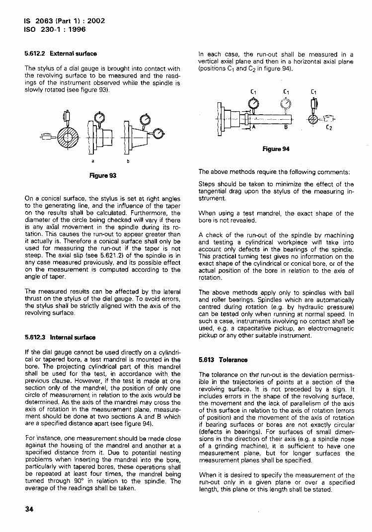
IS 2063 (Part 1 ) :2002
ISO 230-1 :1996
>
5.612.2 External surface
The stylus of a dial gauge is brought into contact withthe revolving surface to be measured and the read-ings of the instrument observed while the spindle isslowly rotated (see figure 93).
a b
Figure93
On a conical surface, the stylus is set at right anglesto the generating line, and the influence of the taperon the results shall be calculated.’ Furthermore, thediameter of the circle being checked will vary if thereis any axial movement in the spindle during its ro-tation. This causes the run-out to appear greater thanit actually is. Therefore a conical surface shall only beused for measuring the run-out if the taper is notsteep. The axial slip (see 5.621 .2) of the spindle is inany case measured previously, and its possible effecton the measurement is computed according to theangle of taper.
The measured results can be affected by the lateralthrust on the stylus of the dial gauge. To avoid errors,the stylus shall be strictly aligned with the axis of therevolving surface.
5.612.3 Internal surface
If the dial gauge cannot be used directly on a cylindri-cal or tapered bore, a test mandrel is mounted in thebore. The projecting cylindrical part, of this mandrelshall be used for the test, in accordance with theprevious clause. However, if the test is made at onesection only of the mandrel, the position of only onecircle of measurement in relation to the axis would bedetermined. As the axis of the mandrel may cross theaxis of rotation in the measurement plane, measure-ment should be done at two sections A and B whichare a specified distance apart (see figure 94).
For instance, one measurement should be made closeagainst the housing of the mandrel and another at aspecified distance from it. Due to potential nestingproblems when inserling the mandrel into the bore,particularly with tapered bores, these operations shallbe repeated at least four times, the mandrel beingturned through 90° in relation to the spindle. Theaverage of the readings shall be taken.
In each case, the run-outvertical axial cdane and then
shall be measured in ain a horizontal axial plane
(positions Cl and C2 in figure 94)
c1 [1 cl
1-l
Figure94
The above methods require the following comments:
Steps should be taken to minimize the effect of thetangential drag upon the stylus of the measuring in-strument.
When using a test mandrel, the exact shape of thebore is not revealed.
A check of the run-out of the spindle by machiningand testing a cylindrical workpiece will take intoaccount only defects in the bearings of the spindle.This practical turning test gives no information on theexact shape of the cylindrical or conical bore, or of theactual position of the bore in relation to the axis ofrotation.
The above methods apply only to spindles with balland roller bearings. Spindles which are automaticallycentred during rotation (e.g. by hydraulic pressure)can be tested only when running at normal speed. Insuch a case, instruments involving no contact shall beused, e.g. a capacitative pickup, an electromagneticpickup or any other suitable instrument.
5.613 Tolerance
The tolerance on the run-out is the deviation permiss-ible in the trajectories of points at a section of therevolving surface. It is not preceded by a sign. Itincludes errors in the shape of the revolving surface,the movement and the lack of parallelism of the axisof this surface in relation to the axis of rotation (errorsof position) and the movement of the axis of rotationif bearing surfaces or bores are not exactly circular(defects in bearings). For surfaces of small dimen-sions in the direction of their axis (e.g. a spindle noseof a grinding machine), it is sufficient to have onemeasurement plane, but for longer surfaces themeasurement planes shall be specified.
When it is desired to specify the measurement of therun-out only in a given plane or over a specifiedlength, this plane or this length shall be stated.
34

IS 2063 (Part l) :2002ISO 230-1 :1996
}
.-.
5.62 Periodic axial slip
5.821 Definitions
5.621.1 Minimum axial play
Minimum axial play is the smallest value of possibleaxial movement of a rotating part, measured at rest ateach of the several positions around its axis (seefigure 95).
5.621.2 Periodic axialslip
Extent of reciprocating motion along the axis of arotating part when the latter is rotated, eliminating theinfluence of the minimum axial play by axial force P ina given direction (see figure 95).
When the axial slip of a rotating part remains withinthe tolerance zone, this part may be considered asfixed in its axial direction.
-E
J = Maximum axial playj = Minimum axial playd = Periodic axial slip
Figure95
5.622 Methods of measurement
5.622.1 General
In order to eliminate the effect of play in thrust bear-ings, a slight force shall be applied to the spindle inthe direction of measurement. The stylus of the dialgauge should be applied to the centre of rotation ofthe front face. Readings are taken while the spindle isrotated continuously at slow speed, force being main-tained meanwhile in the stated direction.
If the spindle is hollow, a short mandrel should befitted with a plane face perpendicular to the axisagainst which a stylus with a rounded contact pointmay bear (see figure 96). Alternatively, a mandrel witha rounded face may be used with a stylus having a flatcontact point (see figure 97). If the spindle has acentre, a steel ball should be inserted for a flat contactpoint to bear against (see figure 98).
Figure96 Figure97
Figure98
5.8222 Applications
Periodic axial slip may be measured with a devicewhich permits a force to be applied along the axis anda dial gauge to be placed on the same axis.
For a lead screw, the axial force can be applied bymovement of the slide when the nut is connected.Horizontal rotating face plates are sufficiently sup-ported on the thrust bearings by their own weight.However, when using a preloaded thrust bearing, noforce need be applied to the spindle.
If it is impossible to place a dial gauge on the axis, thevalue of the axial slip may be obtained by using twodial gauges (see figure 99). Readings are taken atvarious angular positions. The axial slip is equal to thedifference between the largest and smallest meanvalues.
NOTE 26 If the thrust bearing is of the ball- or roller-type,the measurement should be made through at least tworevolutions.
Steps should be taken to minimize the effect of thetangential drag upon the stylus of the measuring in-strument.
Positlun 17
--F’“\/ &“g. .
T+/.
‘y” F!-Axial force
@
Z.._ position2
Figure99
5.623 Tolerance
The tolerance on axial slip defines the limit of the axialslip of the spindle during slow rotation with a slightaxial force. The direction of this force should beindicated (e.g. ‘applying a slight force towards thehousing’). It may be necessary to make two measure-
35
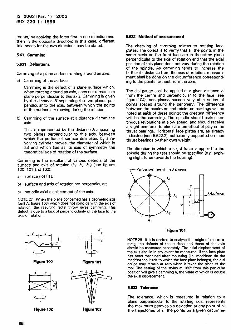
IS 2063 (Part l) :2002ISO 230-1 : 1996
I1
I
ments, by applying the force first in one direction andthen in the opposite direction; in this case, differenttolerances for the two directions may be stated.
5.83 Caroming
5.631 Definitions
Caroming of a plane surface rotating around an axis:
a) Caroming of the surface
Caroming is the defect of a plane surface which,when rotating around an axis, does not remain in aplane perpendicular to this axis. Camming.is givenby the distance Z-Zseparating the two planes per-pendicular to the axis, between which the pointsof the surface are moving during the rotation.
b) Caroming of the surface at a distance d from theaxis
This is represented by the distance h separatingtwo planes perpendicular to this axis, betweenwhich the portion of surface delineated by a re-volving cylinder moves, the diameter of which is2d and which has as its axis of symmetry thetheoretical axis of rotation of the surface.
Caroming is the resultant of various defects of thesurface and axis of rotation (hl, h2, h3) (see figures100, 101 and 102):
a) surface not flat;
b) surface and axis of rotation not perpendicular;
c) periodic axial displacement of the axis.
NOTE 27 When the plane concerned has a geometric axis(part A, figure 103) which does riot coincide with the axis ofrotation, the resulting radial throw gives caroming. Thisdefect is due to a lack of perpendicularity of the face to theaxis of rotation.
“1d d
~
4
. .
Figure100
=+
mc
III.“
‘PFigure101
Figurkl102
TA -! .
,.
/=a
\/ ‘,
I!’
\ /“, :
Figure103
5.632 Method of measurement
The checking of caroming relates to rotating faceplates. The object is to verify that all the points in thesame circle on the front face are in the same planeperpendicular to the axis of rotation and that the axialposition of this plane does not vary during the rotationof the spindle. As caroming tends to increase thefatiher its distance from the axis of rotation, measure-ment shall be done tm the circumference correspond-ing to the points farthest from the axis.
The dial gauge shall be applied at a given distance Afrom the centre and perpendicular to the face (seefigure 104), and placed successively at a series ofpoints spaced around the periphery. The differencebetween the maximum and minimum readings will benoted at eabh of these points; the greatest differencewill be the caroming. The spindle should make con-tinuous revolutions at slow speed, and should receivea slight end-force to eliminate the effect of play in thethrust bearings. Horizontal face plates are, as alreadyindicated (see 5.622.2), sufficiently supported on theirthrust bearings by their own weight.
The direction in which a slight force is applied to thespindle during the test should be specified (e.g. apply-ing slight force towards the housing).
~ Variouspositionsof the dial gauge
A3
Al
Figure104
NOTE 28 If it is desired to analyse the origin of the cam:ming, the defects of the surface and those of the axisshould be measured separately. The axial displacement ofthe axis should in any event be measured. If the face platehas been machined after mounting (i.e. machined on themachine tool itself to which the face plate belongs), the dialgauge may remain at zero when it “takes the place of thetool. The setting of the stylus at 180° from this particularposition will give a caroming h, the value of which is doublethe axial displacement.
5.633 Tolerance
The tolerance, which is measured in relation to aplane perpendicular to the rotating axis, representsthe maximum permissible deviation at any point of allthe trajectories of all the points on a given circumfer-
36

IS 2063 (Part 1) :2002ISO 230-1 :1996
ence of ’the surface to be measured. It includes errorsof shape of the face, the angle of the latter in relationto the axis of rotation, the radial throw and the per-iodic axial slip of the spindle. This tolerance does not,however, include the minimum axial play of the rotat-ing component (see figures 95 and 100 to 102).
6 Special tests
6.1 Division
6.11 Definition of arrors
This clause deals with definitions of errors of divisionof graduated scales, gear wheels, dividing plates,pitch of driving screws, etc.
in general, the following errors maybe recognized:. .-
a)
b)
c)
d)
e)
individual error of division;
successive error of division;
local error of division;
cumulative error’(or steps in a given interval);
total error of division.
16.111 Individual error of dwision
I
! The algebraic difference between the actual value andthe nominal value of division.
\>
~EXAMPLE
\ (ab - a’b’) for the second division of figure 105 (a
~ division is considered here as being the distancebetween two consecutive lines; several divisions forman interval).
,I 6.112 Success-weerrorof dwision
The actual deviation ‘between two successive divi-sions is equal to the algebraic difference of the indi-vidual errors of two divisions.
EXAMPLE
(ab - a’b’) – (bc – b’c’) = ab - bc in figure 105 forthe second division, relative to the third division.
6.113 Local error of division
The sum of the magnitudes (absolute values) of-thetwo greatest individual positive and negative errors inthe interval.
EXAMPLE
Amplitude MN in intewal O to 6 of figure 106.
If all the errors have the same sign in the specifiedinterval, the error of division is equal to the largest ofthe absolute values of individual errors.
6.114 Cumulative error
The difference between the sum of k divisions andthe theoretical nominal value of that sum. The step inthe series may be determined by calculating thealgebraic sum of the individual errors of each divisionor by comparing the actual position of the measuringinstrument pointer with the position which it Wouldhave if the divisions were free from error (seefigure 105).
*
6.115 Totalerrorof dwision
The $um of the magnitudes (absolute values) of thegreatest positive and negative steps included in thegiven interval. This interval may correspond to ‘thewhole of the scale, for instance 360°; amplitude RS infigure 108.
6.116 Graphic representation of these errors
Take a graduated scale, giving, with the theoreticalscale, the steps indicated in figure 105:
1)
2)
3)
If a diagram is drawn (see figure 106), showing asabscissae a series of divisions and as ordinatesthe individual errors, the maximum amplitude MNrepresents the local error of division in interval OtO 6. For the whole series of the scale this localerror is represented by PH.
If a diagram is drawn showing as abscissae aseries of divisions and as ordinates the successiveerrors of division (see figure 107), this diagram willallow the positions of the greatest errors in agiven interval to be found.
If a diagram is drawn showing as abscissae aseries of divisions and as ordinates the position ofevery division in relation to its theoretical position(see figure 108), the maximum amplitude RS,shown by the diagram, represents the total errorof division.
It should be noted that figure 106 can be deducedfrom figure 108 as follows: the ordinate of step k offigure 106 is equal to the difference between theordinates of the steps k and k – 1 of figure 1084).
4) The individual error ab - a’b’ can be put in the form (aa’ + a’b) - (a’b + bb’) or as (b’b - a’a); this expression represents theactual difference between each pair of lines of a given division (see figure 105).
’37

IS 2063 (Part 1) :2002ISO 230-1 :1996
Actualdivision
\
1
Figure105
Determination of local error of division
W MN = local error In the O to 6 Interval~ PH = local error in the O to n intervalLal
s ~+5
: 0 m Division numbers%= v
-3 Y -z~Ne A
No.J—2—3—4—5_6_7_8_ _ vH- - -k-l k---~
tFigure108
Successive errors of division
~0
No. I-22-33-44.55-6 + + + + + + : + + + .. n-1
Figure107
Determination of the total error of division
No. 1 234567++++ ++k-lk. +++n
Hgure 108
38

IS 2063 (Part 1) :2002
ISO 230-1 :1996
6.12 Methods of measurement
As the measurement of errors of division usually re-quires special instruments, reference should be madeto technical notes dealing with this subject.
6.13 Tolerance
Usually, it is not necessary to fix tolerances for eachof the five errors which have been defined. Thus forlinear divisions, the tolerance is always indicated forcumulative error (or step) in a given interval, e.g.300 mm; for circular division, the individual and totalerrors are usually given.
For a geometric test, there are a number of methodsthat can be used. These include using a master screwand dial gauge, gauge blocks and dial gauge, or laserinterferometry.
For a machining test, a workpiece is machined andgiven lengths on it are measured; e.g. in the particularcase of a lathe lead screw, a machining test may becarried out by setting up a workpiece on the machineat any point along the bed and rotating the lead screwover a maximum length of 300 mm. The pitch ob-tained on the” workpiece shall then be checked, forinstance by means of a measuring machine.
6.3 Angular playNOTES
29 When testing machine tools, errors of division normally6.31 DafMtion
include errors caused by the control devices used in thedivision. Individual values of partial errors (i.e. errors of
Angular play of a moving component” is defined by the o
division, off-centre position of the scale in reference to the angle of displacement permitted by the play which
axis of rotation, play in components, etc.) constitute, when may exist in its locking system when the componenttaken together, the total error. These partial errors are of has been locked.little interest to the user of a machine tool.
30 Attention is drawn to the fact that the accuracy given6.32 Method of measurement(testingof the
by a circular dividing mechanism, apart from the intrinsicindexing devicelcomponent)
accuracy of the dividing plate, is subject to deviation ofconcentricity of its mounting on the axis of the machine This test may be made by fixing a bar of sufficient
spindle. length perpendicular to the rotational axis to effect themeasurement over a known distance on an indexingdevice/comDonent. At this distance, a dial aauae is
6.2 Determination of the linear positioning mounted so that its stylus bears against th~ b&. A
deviationsof screw-drivencomponents torque is exerted on the indexing device in onedirection, then in the opposite direction, and differ-
In order to determine these deviations, it may beences are read off the ~al gauge. The value of the
necessary to examine the geometric aspect of all thetorque should be so selected as not to add any sig-
elements which might play a part in the deviations,nificant errors due to deflection of the indexing
and in particular the lead screw.device/component.
Typically, any set of errors observed is made up of6.33 Tolerance
two components, cyclic error and progressive error,ignoring the effect of errors due to repeatability and
The tolerance of angular play is the maximum allowed
time. Cyclic error can be considered as any error angular play, expressed as an angle or as tangent of
component which repeats itself at least once along an that angle.
axis of the machine tool, and progressive error as anon-cyclic error. Especially with machines that pos-ition directly off the lead screw, cyclic error can con- 6.4 Repeatabilityof deviceswith angulartribute a large proportion of the total error. indexing
The accuracy of the pitch of the lead screw is onlyone of the. numerous factors which control the accu-racy of the displacement. Play in certain componentsand deflections may be important. It may be possibleto attach to each of the factors concerned individualtolerances in such a way that the overall tolerancecorresponds to the expected accuracy of the ma-chine.
In machine tool testing therefore, only the deviation ofa screw-driven component need be determined by theuse of geometric tests or practical tests.
6.41 Definition
Repeatability of angular indexing is defined as themaximum difference (range) of angular displacementresulting from a series of trials when approaching anyangular target position under the same conditions ofdirection and speed of approach (where applicable,clamping will take place at the end of each approachand angular play will be included).
For the repeatability of continuous numerically con-trolled angular positioning, see ISO 230-2.
39

IS 2063 (Part 1) :2002ISO 230-1 :1996
6.42 Method of measurement
The test may be made in the same way as the test forangular play, with a bar and a dial gauge. For a givenindexing position, the r l?~l~ifi~ component shall berotated throu h one complete revolution. The maxi-
!mum differen e between the readings made betweensuccessive locking represents the repeatability corre-sponding to this position. Measurements shall berepeated at each indexing position.
6.43 Tolerance
The tolerance of repeatability is the allowed range ofthe measured angular deviations, expressed es anangle or as a tangent of that angle. It irmudes thetolerance of the angular play (in fact, the tolerance ofrepeatability cannot be fixed independently of toler-ances of angular play).
6.5 Intersectionof axaa
6.51 Definition
Two mmparalkl axes are said to intersect when theShortest distance between them lies within the speci-fied tolerance.
6.52 Methods of measurement
6.521 Directmeasurement
The point of intersection of two non-parallel axes canbe determined by means of measurements madebetween the shafts representing these axes, Themethod is the same as that for checking the equidis-tance of two axes with an additional plane (see5.432.1 ). This check is easier ~ the shafts are replace~by two suitably machined bars, with a flat face in aplane parallel to their axes. Measurements are takenbetween the iwo flat faces to determine the deviationof intersection (see figure 109).
‘=%E3Y‘S$iii@
Figure109
6.522 Indirectmeasurement
Indirect measurement can be made by using a separ-ate reference plane, for example a surface platewhich is: set up parallel to the two axes. Independentmeasurements are taken from the reference plane toeach axis and compared.
6.53 Tolerance
The distance between two intersecting axes, when itis not important that axis 1 pass before or behind axis2, is given as follows:
distance of axis 1 to axis 2: & . . . mm
In. ~her cases, when the tolerance depends on oper-ating conditions, it is stated as:
. . . mm when axis 1 is to be higher than axis 2
6.6 Circular=hy
6.61 Definition
A line situated in a’ plane is said to be circular when allits points are contained between two concentriccircles whose radial separation,given value (see figure 11O).
does not exceed
Circularity tolerance
a
Figure110
Circularity may refer either to the shape of a testpiece or to the shape of the path described by amoving component(s).
6.62 Methodsof measurementon testpieces
6.621 Circukity measuringmachinewith rotatingpickupor rotatingtable
In both cases the test piece is centred on the table(small eccentricities may be compensated for). In thefirst case the instrument is rotated around the testpiece (see figure 111), while in the second the tablerotates (see figure 112). A polar diagram is plottedfrom which the circularity is evaluated.
a’/,,,,@ ,,,),,@,
Figure111 Figure112
40

IS 2063 (Part 1) :2002ISO 230-1 : ?996
I
6.622 Coordinate measuring machine
An instrument moving along the circumference estab-lishes the position of each point in the form of X andY coordinates (see figure 113). From this data, thecircular profile and circular deviations are determined.
Y
E=T-lX2xl
rl
x3 I x
Figure113
6.623 Projection of the profile
The profile to be checked is projected onto a screento produce an image of the circumference (see fig-ure 114). The two concentric circles represent thetolerance zone and the circularity deviation.
NOTE 31 This method is limited to smaller test pieces bythe size of the projector.
@
+
Figure114
6.624 Ver+block method
The test piece is supported on two vee-blocks(preferably with an included angle of 1080). The testpiece is rotated and the deviation of circularity ismeasured by a dial indicator (see figure 115).
Figure115
6.63 Measurement of numerically controlled (NC)circular movements
Circular movements may be affected by the appliedfeed rate. The results are comparable to the resultsobtained on machined parts, if diameter and feed rate
are the same for machining and for direct measure-ment of the circular movement.
6.631 Rotating one-dimensional probe
A onedimensional probe, e.g. an electronic probe, ismoved by the NC machine on a circular path. Theprobe is rotated by a special rotary fixture andmeasures displacement relative to a test mandrel(figure 116) or a circular master (see figure 118) or atarget fixed on a special rotary fixture 2 and rotated inconjunction with the probe (see figure 117). The signalof the probe is plotted on a circular diagram (a circulardiagram is shown in figure 11O). The circular diagramcan be produced, e.g. by a synchronized polar plotter,by computer evaluation or by use of an additionalrotary resolver in the rotary fixture and a polar plotter.
I
---- -
1 Onedimensionai probe2 Special rotary fixture3 Test mandrel
Figure116
6.632 Circularmasterand two-dimensionalprobe
A two-dimensional probe is moved by the NC ma-chine on a circular path relative to a circular masterwithout rotating the probe (see figure 118). The pro-grammed diameter of the circular path is chosen sothat the two-dimensional probe keeps in contact withthe circular master. The two signals of the probe areplotted directly on an XY-plotter that produces thecircular diagram (a circular diagram is shown infigure 11O).
41

I
I
I
,I
IS 2063 (Part 1) :2002ISO 230-1 :1996
To computer
r--L-\.
\.
\
)1
/“./’
I
1 Special rotary fixture 12 Special rotary fixture 23 One-dimensional probe4 Target
Figura 117
1 Two-dimensional probe2 Circular master3 Slide of the machine
Figura118
42

IS 2063 (Part 1) :2002ISO 230-1 :1996
//
,/”,/ /
1- ./ /“’.- ..-.
— a;{computer
2
Figure119
6.633 Telescopic ballbar
A telescopic ball bar (see figure 119) is attached bysuitable sockets on the NC machine, one socket onthe table of the machine and one socket on thespindle head which is moved on a circular path rela-tive to the table. A change in the distance R betweenthe two balls is measured. The measurement signal isplotted on a circular diagram (a circular diagram isshown in figure 11O). The circular diagram can be pro-duced e.g. by a synchronized polar plotter or by com-puter evaluation.
6.7 Cylindric”~
NOTE 32 Although the control of circularity, straightnessand parallelism by means of a cylindricity tolerance mayappear to be a convenient technique, the measurement ofcylindricity in accordance with its definition may prese’ntconsiderable difficulties. It is recommended that individualck,aracteristics comprising cylindricity be tolerance separ-ately, as appropriate to the part concerned.
6.71 Defintilon
A surface is said to be cylindrical when all its pointsare contained between two coaxial cylinders of revol-ution whose radial separation does not exceed a givenvalue (see figure 120).
6.72 Methods of measurement
All the procedures involve a measurement of dimen-sional deviation with respect to a reference of cylin-dricity.
BallSocket
T CWfulriClty tolerance
r-l/“
.—. — -—. — .
IFigure120
6.721 Coordhate measuringmachine
The circular profile of each section is determined byscanning the circumference with a probe (seefigure 121).
zI Y
YI
/ /
Figure 121
43

IS 2063 (Part 1) :2002ISO 230-1 :1996
I(
-.\
I
6.722 CircuIar”~ measuring machine with rotatingprobe or rotating table
In both cases the test piece is centred on the tableand the probe can be moved parallel to the axis of therotating table. In the first case the probe is rotatedaround the test piece (see figure 111), while in thesecond the table rotates (see figure 112). The cylin-dricity is determined by superimposing the polar dia-grams taken at various sections.
NOTE 33 This method gives high accuracy with easyalignment, but requires expensive equipment.
6.723 Veeblock method
The test piece is supported on two vee-blocks(preferably with an included angle of 1080). The testpiece is rotated and the deviation of circularity ismeasured by a dial indicator (see figure 115), Theprocedure is repeated at a number of sections toprovide an indication of cylindricity.
within given maximum and minimum diameters (seefigure 122).
6.62 Methods of measurement
6.621 Micrometer or similartwo-point measuringinstrument
Readings are taken at each band in one plane only.Measurements can be taken while the test piece isstill on the machine tool (see figure 123).
DI D2 ~ Dk
Ww
--1 1 1--1 r-l-’+ +. .;IllL–J L-J L-;
Optional steps
Figure122 Figure123
6.8 Consistencyof machineddiameters6.822 Heightgauge
6.81 Dafhition
Diameters are said to be consistent when the vari-ation between machined diameters at intervals alongthe test piece, measured in a single axial plane, fall
The test piece is fixed horizontally between centres orsupported by vee-blocks. The highest and lowestpoints of the machined diameters are measured usinga height gauge (see figure 124).
Height gauge
7
Figure124
44
IS 2063 (Part l) :2002ISO 230-1 :1996
?’
I
I
AnnexA(informative)
Instrumentsandequipmentfor testingmachinetools
A.1 General
The measuring equipment describedused for the geometric testing of
in this annex ismachine tools.
Where necessary, reference is ‘made to the appro-priate International Standards.
Clauses A.2 to A.5 describe the precision instrumentsused for the testing of machine tools. Their accuracyis that of measuring instruments for inspection pur-poses (not for standard rooms).
Where practicable, measurement errors for theseinstruments should be equal to or less than 10 YOofthe tolerance zone for the feature being checked.
The measuring equipment should be calibrated atregular intervals in comparison with known referencestandards, with respect to the metrological require-ments. If necessary, calibration charts shall be sup-plied to show the condition of the equipment.
Measuring equipment should not be used until it hasbeen allowed to stabilize at the ambient temperature,and be kept as stable as possible during the testprocedure.
Care should be taken to prevent disturbance to theequipment due to vibrations, magnetic fields, electri-cal interference, etc.
A.2 Straightedges
A.2.1 Description
A straightedge is a material representation, to a givenaccuracy, of a straight reference line, by reference towhich deviations from straightness or flatness of asurface may be determined.
There are two principal types of straightedge:I—
—
.
—
the bow-shaped straightedge [see figure A. 1 a)]with a single edge;
the straightedge with two parallel faces.
The latter type may be:
single-section with a solid or lightened web [seefigure A.1 b)].
of plain rectangular section [see figure A.1 c)];
Straightedges should preferably be heat-treated andstabilized.
A.2.2 Accuracy
For testing machine tools, straightedges shall complywith the following conditions.
A.221 Permissible deflection
The moments of inertia of the sections shall be suchthat the natural deflection of the straightedge, whenresting on two supports situated at the extreme ends,shall not exceed 0,01 mm per 1000 mm.
The exact value of this naturaJ deflection, whichrepresents the maximum deflection of the straight-edge, shall be marked on one of its faces.
AZ.22 Flatness and straightnessof workingfti
The errors in flatness and straightness of the workingfaces of straightedges when supported at the mostfavorable positions (see figure A.1 ) shall not exceedthe following a-mounts:
(2+ o,olL)1000
where L k the working length, in millimetres.
In addition, the errors over any length of 300 mmshould not exceed 0,005 mm.
A.2.23 Parallelism of working faces
For straightedges with two parallel faces, the error inparallelism of the working faces, in millimetres, shallnot exceed 1,5 times the tolerance on their streiight-ness, viz.
1,5 (2+ O,OIL)
1 000
A.2.24 Straightness of side faces,in millimatras
10(2 + O,OIL)
1000
A.2.25 Parallelismof sidefaces,in millimatras
15(2 + 0,0L5)
1000
45

IS 2063 (Part 1) :2002ISO 230-1 : 1996
wa)
L
w
“1000 000 000 0001.——.2L19 !_ 51./$ t 2L19
Y“_ - — Best supports ~
wI I
c)
w 2M9 ~. 5L19 ~_ 2L/9
wSs
I!llw
Ss
ISs
w
ISs
W = working faceS = side face
FigureA.1— Positionsof bestsupportsfor straightedges
I
I
!
III
I
A.2.26 Squareness of side faces to working faces
~ 0,0025 mm for a measuring length of 10 mm
A.2.27 Sufface finish of working faces
The working surfaces used when measuring shouldbe either finely ground or well scraped.
A.2.28 Width of the straightedge
When the straightedge is used with a level, the widthof the working faces shall be not less than 35 mm.
A.2.3 Precautionsin use
Straightedges are generally used horizontally, eitherresting on their side face with their working faceve~ical, or resting on supports with their working facehorizontal.
In the latter case, the supporting positions should bechosen preferably so as to minimize the natural de-flection. In case “of straightedges of a uniform cross-section, their supports should be separated by 5L/9,
46
and situated at a distance of 2L/9 from the ends (seefigure A.1 ). These particular positions for the supportsshall be clearly marked on the straightedge.
When a straightedge is not resting on its best sup-ports, and particularly when it is supported at theextreme ends, its natural deflection should be takeninto account.
Table A.1 shows, as examples only, five straightedgesof various lengths which would conform to theseconditions. The natural deflection depends directlyupon the modulus of elasticity E of the material used.The values of the deflection given in table A.2 corre-spond to straightedges made of ordinary cast iron:E = 98 kNlmmz. In the case of steel,E = 196 kN/mmz, the deflections would be halved. Inthe case of high-duty cast iron, where for exampleE = 147 kN/mmz, the deflection would be pro-portional to the modulus of elasticity.
A.3 Testmandrelswith tapershanks
A test mandrel represents, within given limits, theaxis which is to be checked, either for run-out or forposition in relation to other components of the ma-chine.

IS 2063 (Part 1) :2002ISO 230-1 :1996
TableA.1— Straightedges
~trnensionsinrnillirnetres-..
Length Broadtype Normal type
No. Worldng Totall} Diagram Section MaaazJ section Massz
1 300
e340 w “* ‘: ‘i ‘:
2 500A
“- 300 ‘B 1 “* 4 % 3
3
8“” : ~“ “* 5
4 1000 1040 ‘~ ‘* 12Bestsupparts
&holes0100 6 ho~es@8012
\
5 1600 1640
~ R
w-[ ‘Q O)”m ~’ ~ ,3
A 910 B N
8est supports50
1) The total length is a little greaterthan the working length,so that inspectionsmay be madewithout havingto use the ends of th(straightedge, which are more di~tcult to machine accurately.
2) Masses are relative to plain cast iron; they would be slightly greater in the case of steel.
47

I
IS 2063 (Part l) :2002ISO 230-1 :1996
TableA.2— Accuracy requirements corresponding to the fme atraightadgaa in table A.1
Dimensions in millimetres
Working faces Sida facaa
No.Deflection with supports
Dimen@ons Squareness orat extreme end in the straightnassz~ Paraiieiism Straightness
casa of plain cast iront~Paraiiefism perpendicularity to
working faces
300 Nwmal1 300 Broad 0,001 0,005 0,0075 0,050 0,075 k 0,008
2500 Normai500 Broad 0,003 0,007 0,0105 0,070 0,105 *0,012
3 800 0,004 0,010 0,0150 0,100 0,150 * 0,020
4 1000 0,008 — 9,012 C,018O 0,120 0,180 t 0,025
5 1600 0,016 O,w 8 ~,;27 O 0,180 0,270 * 0,045
1) E =98 kN/mm2
2) Local tolerance= 0.005 mm over 300 mm. I
A.3.1 Description
Test mandrels have @ tapered shank for inserting inthe socket of the machine to be tested, and a cylindri-cal body which is used as a reference for themeasurements [see figure A.2 a) and b)]. They aremade of hardened and stabilized steel, either unplatedor plated with hard chromium.
They also have the following characteristics:
a)
b)
c)
d)
ground and lapped centres, recessed for protec-tion at the ends, for purposes of manufacture andinspection;
four reference lines r spaced at 90° (1, 2,3 and 4);the distance between the marks at the two endsof the cylindrical part represents the measuringlength L 75 mm, 150 mm, 200 mm, 300 mm or500 mm;
in the case of relatively slow Morse and metrictapers, the mandrels are self-holding in the socket[see figure A.2 a)]. A threaded portion is providedto receive a nut for extracting the mandrel fromthe socket;
in the case of relatively steep tapers [see fig-ure A.2 b)], a tapped hole is provided for fixing th-emandrel by means of a threaded retaining bar, or aretention knob as used with an automatic tool-changing device [see figure A.2 c)].
Finally, in order to avoid the mandrel being reversedend for end when grinding, the instrument may alsobe fitted with an extension P of a length from 14 mmto 32 mm and a diameter slightly smaller than that ofthe cylindrical part [see figure A.2 d)].
Figure A.3mandrels.
shows, as examples, a series of suitableThe external dimensions (diameter and
length) and the profile of the bore of these mandrelshave been determined so that (with the exception ofthose with Morse tapers No. O and No. 1) the deflec-tion at the free end, due to the overhanging weight ofthe mandrel and the deflection caused by the press-ure of a dial gauge upon it, are negligible when testingwith these instruments.
Table A.3 gives the values of the deflections. Thesedeflections have been calculated for E = 206 kN/mmz;even for somewhat smaller values (E= 176 kN/mmzto 186 kN/mm2) the deflections are still negligible.
In the case of the 7/24 taper, table A.4 indicates thecorrespondence between the cylindrical portions andthe dimensions of the cone.
If the mandrels with dimensions differing from thosein figure A.3 are used for checking alignment, theirdeflection should be distinctly marked on them andtaken into account when testing machines.
Finally, attention is drawn to the fact that mandrelsabove 5 kg in mass tend to cause deflection of thespindle into which they are inserted.
A.3.2 Accuracy
Mandrels should meet the requirements given intables A.3, A.4 and A.5.
In order to obtain a good fit inaccuracy of the taper shanksthat of taper plug gauges.
machine sockets, theshould correspond to
46

IS 2063 (Part 1) :2002ISO 230-1 :1996
Dimensions in millimetres
II
I
27
-4 reference lines h)
,20, 1-4 reference lines (r) &
20 14 reference lines (r) I 5
$4 “
Y
,1c) *
-N .— .— .— ._ ._ ._ e
E
-4 reference lines (r) k1
4
FigureA.2 —The mandrels of Morse and metric tapers
Table A.3 — Test mandrels — Deflection values
Mandrals without axtansion Mandrals with axtansion
Typa A Type C
Approxi- ~atural Additional Total Approxi- ~atura, AdditionalNo. Working mate daflaction undar mata deflection under Total
deflec-Obsar-
of tapar Iangth total load P acting deflac- total daflec- Ioad P acting deflac-tionlj tion tionl)
vationsmass on fraa end mass on free end tion
P Pmm kg mm 9 mm mm kg mm 9 mm mm
Morsa O 75 0,11 0,00065 50 0,0009 0,0016 0,12 0,0009 50 0,0009 0,0018}
Deflections
Morse 1 75 0,13 0,0005 50shall be taken
0,0007 0,0012 0,14 0,0007 50 0,0007 0,0014 mto account
Morse 2 150 0,73 0,0015 100 0,0006 0,0021 0,79 0,0019 100 0,0006 0,0025Morse 3 200 0,96 0,0018 100 0,0007 0,0025 1,09 0,0022 100 0,0007 0,0029
Morse 4 300 2,2 0,0033 100 0,0007 0,004 2,28 0,0039 100 0,0007 0,0046
Morse 5 300 3 0,0026 100 0,0006 0,0032 3,14 0,0031 100 0,0006 0,0037 Deflecoons
Morse 6 500 10 0,0058are neghgible
100 0,00035 0,0062 10,32 0,0066 100 0,00035 0,007
Metric60and
larger 500 15 0,0035 100 0,00015 0,0037 15,24 0,0039 100 0,00015 0,0041
1) The figures shown correspond to the difference in netural deflection at the two ends of the measurement length,
49

IS 2063 (Part 1) :20021S0 230-1 :1996
Dimensions in rnillirnetres
t335
-1Morse 4and 5 A
o
Partial +u-l
E
-“x—m
6m@N
:+1
Morsei-= 235
I
Morse 21= 175 I
mN s* 8,
f - -e- ~.— .— .
a“19 ~ !
wide, spaced at 90”
The four lines 0,1 mmwide, spaced at 90”,marked on the cylin-drical part, arereproduced in align-ment and numbered 1to 4 on the mandret end.
x
MorseNos.O,1and2
@
m-. . ycl
a
- R 0,5
Morse Nos.3. 4.5 and 6Metric 80, etc.
100Morse O and 1 g
M15x IFs *
- -+ - ~.— .
ci- 14 ! 15 4 lines 0,1 mm- “ -
‘wide, spaced at 90” RNOTES
1 An extracting nut should be supplied with each mandrei.
2 For particulars of the tapered shank, refer to the current ISO specification; the dimension D, will be that of the specification. The mandrelshall have a ground and lapped centre of the protected type at each end.
3 The part indicated in dashed line is that of the mandrel shown in figure A:2 d); this extemsionP has been added to assist manufacture. Thetotal length will be increased by this amount, as also that of the first bore, the end piug being unchanged.
FiguraA.3 — Taat mandrala

IS 2063 (Part 1) :2002ISO 230-1 :1996 -
TableA.4 — Test mandrels — Cylindrical parts of 7/24 tsper shanks
50
Taper 7124No. 30 40 45 Shortmandrel Long mandrel
Measuring length, 1 200 mm 300 mm 300 mm 300 mm 500 mm
Mandrel Morse No. to which cylindricalpati isadapted 3 4 and 5 4 and 5 4 and 5 6
TableA.5— Testmandrels— Requirements
Dimensions in millimetres
Measuring length,1 75 150 200 300 500
Total run-out along entire length 0,002 0,002 0,003 0,003 0,003
Maximum variation in diameter of cylindricalpart 0,002 0,002 0,003 0,003 0,003
Taper tolerance Accuracy of taper shanks should correspond to that of taper plug gauges
In the case of hollow mandrels, the end-plugs shouldbe rigidly and securely fixed in such a manner that nosubsequent distortion will take place (e.g. by freezingfit).
The machine tests using a mandrel consist of mount-ing it between centres and testing the run-out at anumber of’ points equally spaced along the axis .of the
! mandrel, and also measuring the diameters of the
Icylindrical part in the two axial planes correspondingto the four reference lines. The tolerances given in
~
table A.5 shall be complied with in relation to themeasuring length.
\,p Finally, the cylindrical portion shall have a very finely
~ , ground surface so as to reduce friction at the contactpoint of the dial gauge stylus.
!
i A.3.3 Precautions in usa
I The taper shank of the mandrel should be well fitted...\ in the machine spindle; this may require attention toi the spindle.
I To measure the run-out, the mandrel should be suc-
~ cessively inserted in the spindle in four positions,each at 90° to the previous, and the mean of the fourresults taken.
To check the accuracy of the lateral position of acomponent or of parallelism, the test shall be madesuccessively on two opposite reference lines on thecylindrical surface of the mandrel, turning the mandreland the spindle through 180°.
After inserting a mandrel in a spindle, time should beallowed to elapse for dissipating the heat of the handof the operator and to allow the temperature to stabil-ize.
In the case of mandrels with Morse tapers No. O andNo. 1, it is necessary to take into account their naturaldeflection. They should only be used with a dial gaugereading to 0,001 mm and having a force not exceed-ing 0,5 N. The dial gauge should preferably be appliedto the underside of the mandrel so as to oppose itsnatural sag.
A.4 Mandrelsbetwaencantres
A.4.1 Description
Whilst a test mandrel with a taper shank serves as amaterial representation of an axis of rotation, a mirn-drel mounted between centres (see figure A.4) rep-resents simply a straight line passing between twopoints. The axis of such a mandrel should be straightand its exterior surface truly cylindrical.
It has, at each end, four reference marks located intwo perpendicular axial planes, and centres recessedfor protection.
These mandrels are generally manufactured fromweld-free hot-drawn steel tubes. The tubes are fitted.with terminal plugs with ground and lapped centreswhich serve for machining and testing. The end plugsshould be rigidly and securely fixed in such a mannerthat no subsequent distotiion will take place. Theoutside of the tube is ground to obtain the requireddegree of cylindricity. The machining operation re-quires wall thickness which is not usually available inordinary tubing; it is necessary to use reinforced high--pressure tubing. The metal must be stabilized beforefinal grinding. The cylinder should be hardened andmay be hard chrome-plated to increase its resistanceto wear. ~

IS 2063 (Part 1) :2002ISO 230-1 :1996
r
I
I
I
-L. __. __-__ -__- _--_-l
>Q
I
-----------
12 mm
1- L-1
FigureA.4 — Mandrel for mounting between centres
A.4.2 Accuracy
The only real problem concerning test mandrelsbetween centres is achievement of the necessa~accuracy in their manufacture. As alignment of ma-chine tools needs to be measured to an accuracy of0,01 mm on 300 mm, a cylindrical mandrel should bestraight to at least 0,003 mm over the same length.
Above 300 mm, mandrels should be tubular, the wallthickness being so chosen as to reduce the mass, butnot at the expense of rigidity.
Mandrels above 1600 mm in length present difficult-ies in manufacture and their mass tends to renderthem unmanageable. For longer lengths, it is necess-ary to use alternative test methods such as opticalapparatus, stretched wire and microscope, etc.
Examples are given in table A.6 of four ranges ofmandrels suitable for carrying out the majority of testsrequired on machine tools.
Mandrels are inspected by mounting them betweencentres and checking at regular intervals, e.g. every50 mm or 100 mm, the run-out and the diameters intwo axial planes at 90°. These planes correspond tothe four reference lines which are marked on thecylindrical surface.
1
eb)
zEEEw
A.4.3 Precautions in use
To check parallelism, readings are taken on onereference line on the cylindrical surface of the mandreland then on the opposite one after turning the man-drel through 180°. Thesq two sets of readings arethen repeated on the same pair of reference linesafter turning the mandrel end for end. The mean ofthese four sets of readings then gives the deviationfrom parallelism. This method of measurement servesto eliminate most of the causes of deviation arisingfrom inaccuracies of the mandrel.
A.5 Squares
The principal types of squares are:
1)
2)
3)
the square represented by a plane and an edge atright angles, with or without a reinforcing rib [seefigure A.5 a)];
the cylindrical square, represented by an axisperpendicular to a plane [see figure A.5 b) andA.5 c)];
the block-type square with or without reinforcingribs [see figure A.5 d)].
a)
52
c) d)
FigureA.5 — Principal types of squares

IS 2063 (Part 1) :2002ISO 230-1 :1996
Table A.6 — Cylinder types
Accuracy
OutsideMass with-
Overall length Inside Maximum
diameter diameterout end- Natural variation in Maximum Surface
plugs daflectionl) diameter run-out finish
L D d
mm mm mm kg mm mm mm
150< L==300 40 0 l,5t03 0,00002 to 0,00004 0,003 0,003
301< L <500 63 50 2,7 fO 4,5 0,0001 to 0,0007 0,003 0,003
501< L<1OOO 80 61Finely ground
8,3 to 16,5 0,0005 to 0,008 0,004 0,007
001< L< 1600 125 105 28,2 to 45 0,003 to 0,019 0,005 0,010
1) E = 206 kN/mmZ
A.5.1 Description A.5.24 Tolerence on rigidity of squares with twoarms
The dimensions of squares do not generally exceed500 mm. To check squareness over a greater length,it is preferable to use optical methods, which aremore practical.
Squares are made of steel, cast iron or other suitablematerial; they may be hardened and stabilized.
1 A.5.2 Accuracy
I
i
Squares shall be constructed so as to comply with thefollowing requirements.
~I A.5.21 Tolerances on flatness and straightness
I
The tolerance on flatness of squares with arms, or\ tolerance on straightness of cylindrical squares, is
given by:I
(2+ O,OIL)I1 000
1!
where L is the working length, in millimetres.~
A.!i.22 Tolerance on squareness
0,005 mm for any measuring length of 300 mm
The angle may be either smaller or larger than 90°.
For squares of the type shown in figure A.5 a), bothworking faces of the vertical limb should be perpen-dicular to the base.
A.5.23 Finish of the working surface
The working surfaces shall be fi~ely ground or wellscraped.
When a load of 2,5 N is applied at the extremity of theweaker of the two arms of the square in a directionparallel to the other arm (see figure A.6), the deflec-tion, in millimetres, should not exceed:
(0,7451000
where L k the working length of the weaker arm ofthe square, in millimetres.
1-1
Figure A.6 — Measurement of rigidity of squareswith two arms
A.5.3 Precautions in use
The tolerances of squareness which are ordinarily meton machine tools vary from 0,03 mm/1 000 mm to0,05 mm/1 000 mm. Squares serve conveniently fordealing with these tolerances. For finer tolerances,however, account should be taken of the error of thesquare used. Alternatively, some other method ofmeasurement which does not involve the use of asquare may be considered.
53

IS 2063 (Part 1) :2002ISO 230-1 :1996
I
I
A.6 Precision levels
Spirit levels (see figure A.7) and electronic levels (seefigure A.8) are the two Tipes of precision levels.
Both types of levels have twc main functions:
a) determination of absolute level;
b) comparison of small changes of angle or slope.
The required accuracy of the test to be performeddetermines the sensitivity and type of level required.
A.6.1 Spirit levels
A.6.11 Description
A level may be fitted with a micrometer screw or withgraduation lines on the tube, with or without adjust-able screw.
In the first case, the changes in slope are read cm thedeviation of the micrometer; in the second case theyare read directly on the graduation lines of the tube.
The constant of a level or apparent sensitivity, n, isthe change in tilt, expressed in millimetres per milli-metre (or in seconds of arc), which produces a dis-placement of the bubble by one division.
A.6.12 Accuracy
It is recommended that, for testing machinetools, levels should have an accuracy of0,005 mm/l 000 mm to 0,01 mm/1 000 mm andthe bubble should move through at least onedivision for a change of angle not greater than0,05 mm/l 000 mm.
The flatness of the base should complyfollowing tolerances:
0,004 mm for L s 250 mm;
0,006 mm for 250 mm < Ls 500 mm.
with the
In the case of a level having a continuous unrelievedflat base, it is important that the base be not convex.
A.6.13 precautionsin use
Tests with a level should be carried out in as short atime as possible, and measurements should be re-peated in the reverse direction in order to take ac-count of temperature variations which may occurbetween the initial and final readings.
As their glass tubes are liable to deform with age,spirit levels should be recalibrated at regular periods.The date of each calibration should be given on thelevel’s calibration sheet.
A.6.2 Ektronic levels
A.6.21 Descriptionand accuracy
Electronic levels, in comparison with spirit levels, aremore sensitive, respond faster, are less affected bytemperature and can be interfaced to automatic plot-ting devices.
A.6.22 Precautionsin usa
As the magnification of electronic levels is adjustable,it is important that the magnification be periodicallycalibrated using a sine bar to tilt it through a knownangle.Some electronic levels’ are adversely affectedby magnetic force, e.g. magnetic chucks or magneticdial indicator bases.
Ensure that the surface at 90° to the direction ofmeasurement is level within the instrument manufac-turer’s specification. When checking for absolutelevel, two readings with the level should be taken, thesecond being made after the level has been rotatedthrough 180°
The two readings should be algebraically addedtogether and divided by two, to provide the meanreading.
I
I
FigureA.7 — Adjustablespiritlevel
54

,
When making a topographical survey, it is importantto know the distance L (see figures A.7 and A.8)between the middle of the support points, and to takereadings by moving the level and its support in in-crements of L between each reading, ensuring thatthe trailing foot occupies the same point that theleading foot occupied during the previous reading.
HLI LL
1
FigureA.8 — Electronic level
A.7 Linear displacement probes
Two types are shown as examples: dial gauges andelectronic probes.
A.7.I Dial gauges (seefigures A.9and A.1O)
For details of dial gauges, reference should be madeto ISO 463. Ordinary tests can be made with 0,01 mmdial gauges, but for more precise tests (e.g. run-out ofa spindle of a machine tool), dial gauges with0,001 mm resolution should be employed.
-,
FigureA.9 — Dial gauge
FigureA.1O— Dialgauge
IS 2063 (Part 1 ) :2002
ISO 230-1 :1996
h is emphasized that the principal characteristics ofthese instruments are:
a)
b)
c)
d)
e)
the curve of errors;
the maximum value of hysteresis;
the extreme values of the measuring force at thebeginning and end of the stroke of the stylus;
the maximum local variation of the measuringforce (this force generally has different values forthe in-and-out movements of the plunger at everyposition in the stroke);
the repeatability when used upside down.
It is recommended that the dial gauges used have ashort stroke and, in particular, that they have lowhysteresis and a light contact force.
A.7.2 Electronic probes
Electronic probes consist of a gauge head connectedto an amplifier. The amplifier is capable of displayingthe linear displacement of the gauge head to a highaccuracy. The gauge head can be either cartridge-head or lever-head design (see figuresA.11 and A.1 2).
Figure”A.11— Cartridgeheed
FigureA.12 — ~Ver haed
A.7,3 Precautions in use
Supports for dial gauges and electronic probes shouldbe of sufficient stiffness “to prevent unwanted errors.
The stylus of the dial gauge or electronic probe shouldbe normal to the surface to be checked, to avoid inac-curacies.
55

IS 2063 (Part 1) :2002ISO 230-1 :1996
t!
I
A.8 Surface plates
A.8.1 Description
The size of surface plates range from 160 mm x100 mm to 2500 mm x 1600 mm. Cast-iron platessmaller than 400 mm x 250 mm are provided withsuitable hand grips to permit n-a;ipulation (see fig-ure A.1 3). Cast-iron plates larger than 400 mm x250 mm have detachable handles. Granite plates donot have handles (see figure A.14).
FigureA.13 — Typical steel or cast-iron p!ete
Figure A.14 — Typical granite plate
A.8.2 Precautions in use
Supporting feet of surface plates up to and including1000 mm x 630 mm are provided with three adjust-
able suppotiing feet; safety feet to prevent tipping areprovided at the single foot end of surface plates of400 mm x 250 mm and longer. Surface plates largerthan 1000 mm x 630 mm are supported on five ormore adjustable feet (see figure A. 15).
t-
L 0.
:NII
A+M B
I
> - — ‘—- —-—-— --— -q
1
kc
N
A, B, C:
M, N:
I +N
_2L/9 2L/9 !
Supporting feet of the surface plate which ensureminimum deflection under its own weight.
Safety support feet.
Figure A.15 — Position of feet of largesurface plates
A.9 Microscopes with taut-wire (see
figure A.16)
A.9.1 Description
The measuring instrument comprises a microscopewith a reticle and micrometer adjustment to indicateits position accurately in respect to the taut-wire.
f7-Microscope
1
1I
Taut-wire
Hgure A.16 — Microscope with taut-wire
56

IS 2063 (Part l) :2002ISO 230-1 :1996
t
A.9.2 Accuracy
The microscope can be adjusted on the machine bymeans of a precision level (which may be integral withthe microscope support). The two ends of the wireare lined up by means of the cross-hairs of themeasuring microscope. Readings are taken in thehorizontal plane as the table is traversed.
A.9.3 Precautions in use
Care should be taken when handling the wire, whichshould be of sufficient tension and free from kinks.The wire diameter should be as small as possible, inany case not more than 0,1 mm. Long beds to 20 mand more can be tested without the need for specialprecautions.
A.1O Alignmenttelescopes
A.1O.I Description
The alignment telescope (figure A. 17) with access-ories is designed to test straightness, parallelism andsquareness. Through an arrangement of lenses con-tained in tubular housing, a view of horizontal andvertical cross-wires can be projected onto a target.
A.1O.2 Accuracy
The vertical and horizontal displacement of the cross-wires to the target is measured directly in millimetres
Sphericalt!“1
using the micrometer dials (figure A.1 8). The gradu-ated focusing dial varies the position of the focusinglens, enabling targets to be focused from zero toinfinity. The focus of the cross-wires is achieved atthe eyepiece. The telescope is most commonlymounted on a horizontal base (figure A. 17) containinga spherical trunnion to allow lateral and vertical adjust-ments of the line of sight. Straightness can bemeasured by moving the target along the line of sight(figure A.1 9). Accessories to accommodate precisionlevels and optical squares will extend the capacity ofthe instrument to measure parallelism and square-ness.
Figure A.18 — View of cross-wires.targetandmicrometerdials
wn
Lateral adjuster 1
l.-
L Mi~r~meter dial
Vertical adjuater
Eyepiece
Figure A.17 — Alignment telescope mounted on a horizontal base
57

IS 2063 (Part 1) :2002ISO 230-1 :1996
A.1O.3 Precautions in use
The following precautions should be taken in use.
a)
b)
c)
d)
e)
Avoid using where there are changes in tempera-ture which could cause undue refraction.
Ensure that the base of the magnetic targetmount is clean.
Ensure that the micrometer dial. readings areinterpreted -correctly, i.e. +ve is not confused with-ve. A suggested rule of convention is t~“ LURD” principle (see figure A.20) (i.e. left, up,right, down).
Ensure that focus settings are sharp.
Whenever possible, ensure that the instrument ismounted rigidly.
A.11 Autocollimators(see figure A.21 )
A.11.l Description
Target wires take the place of the light source andthese are illuminated by a lamp and condenser at the
side, the light being reflected along the optical axis bya transparent reflector.
The reflected image of the wires, formed in the sameplane as the wires themselves, is viewed through alow-power microscope fitted with a micrometereyepiece, by which variations ‘in the position of thereflected image are measured.
A.1 1.2 Accuracy
The micrometer drum is graduated in half-seconds,and with a good reflecting surface it is possible toobtain repeat readings to within 1/4 second.
A.11.3 Precautionsin use
During measurements, the autocollimator telescopeshould be made integral with the component bearingon the line to be chedked, and should be mounted ona steady rigid support. Any deflection of the machineshould be noted.
It is important to avoid vibrations or rapid changes oftemperature.
,
I
FigureA.19— Checkingstraightnessby measuringdisplacementfrom the lineof sight (L.O.S.)
uI
\
o
FigureA.20 — LURD principle FigureA.21— Autocollimator
56

IS 2063 {Part 1) :2002[S0 230-1:1996
A.12 Sweep opticalsquares(see5.324)
A.12.I Description
The sweep optical square is used in conjunction withthe alignment telescope and three datum targets toestablish a reference plane which enables a surface tobe checked for flatness (see figure A.22). The tele-scope is mounted in a frame which carries a rotatingoptical unit housing a pentagonal prism. The framecontains adjustable supports to bring the plane sweptby the instrument to the centre of the datum targets.
A.12.2 Accuracy
The targets are focused as described in A.1 O, and amicrometer dial on the rotating optical unit measwesthe vertical displacement of the targets with re’spectto the cross-wires.
A.12.3 Precautionsin use
a) Avoid using where there are changes in tempera-ture which could cause undue refraction.
b)
c)
d)
e)
Ensure that the base of the magnetic targetmount is clean.
Ensure that the micrometer dial. readings areinterpreted correctly, i.e. +ve is not confused with-ve. A suggested rule of convention is the“ LURD” principle (see figure A.20).
Ensure that focus settings are sharp.
Whenever possible, ensure that the instrumentsare mounted rigidly.
A.13 Laserinterferometers
A.13.1 Description
The development of the laser interferometer has pro-vided the machine tool industry with a high-accuracystandard which can be used on machine tools of alltypes and sizes. The stabilized helium-neon lasercurrently represents the state of the art in laser lengthstandards, and in practical terms has become theaccepted length standard.
t
Fourth target (can be placed anywhere)
Figure A.22 — sweep optical square setup
59

IS 2063 (Part 1) :2002ISO 230-1 :1996
A.13.2 Accuracy
The accuracy of the interferometer is determined bythe laser wavelength, and is better than 0,5 parts permillion.
The laser interferometer is capable of measuring fiveof the six degrees of freedom: linear positioning, hori-zontal straightness, vertical straightness, pitch andyaw, as well as squareness between two axes. All sixdegrees of freedom are of equal impmtance sincepositioning errors, resulting from unwanted angularmotions or from out-of-straightness translations, canbe potentially larger than the linear positioning errorson a coordinate axis.
Other sources of error to be considered before com-mencing measurements are:
a) Environmental error
For linear measurements it is necessa~ to realize thatthe absolute accuracy of the laser interferometer isdirectly determined by how accurately the ambientconditions are known and, in fact, how stable theyare. An error of approximately 1 part per million will beincurred for each error of 1 ‘C in ambient tempera-ture, 2,5 mmlig in absolute pressure and 30 YO inrelative humidity. These errors can be partially over-come by using either manual compensation or one ofthe automatic compensators which can be connectedto the laser display.
However, most important is that the conditions re-main stable during the test period.
b) Machine surface temperature
Another significant source of error in interferometricmachine tool evaluation is the effect of temperatureon the machine tool itself. For machine tools that usea steel lead. screw to determine carriage position, thiseffect represents an expansion of approximately
0,0000108 mm/mm for a 1 “C rise in the lead screwtemperature. If the total carriage travel is 1000 mm,this effect represents a potential change in the leadscrew length of 0,0108 mm per ‘C change in tem-perature.
c) Deadpath error
Deadpath is an error associated with changes in theenvironmental conditions during a measurement. Insimple terms, it is an error due to an uncompensatedlength of laser-light path, and it occurs when the at-mospheric conditions surrounding the laser beamchange (causing a change in the laser wavelength)and when the temperature in the material on whichthe optical interferometer and target reflector aremounted changes (causing the distance between theinterferometer and retroreflector to increase or de-crease) (see figure A.23).
The deadpath area of the laser measurement path isthe distance between the optical interferometer andthe reset (or O) position of the measurement (Ll ). Ifthere is no motion between the optical interferometerand the corner cube (retroreflector) and the environ-mental conditions surrounding the laser-beam pathchange, then the wavelength will change over theentire path (J51+ L2). If the velocity-of-light com-pensation value changes to correct for the new en-vironmental conditions, the laser measurementsystem will correct for the laser-wavelength changeover the distance Lz, but no correction will occur overthe deadpath distance L1.
d) Cosine error
Misalignment of the laser-beam path with the axis ofmotion of the machine tool will result in an errorbetween the measured distance and the actual dis-tance travelled. This misalignment error is usuallyreferred to as cosine error, because the magnitude ofthe error is proportional to the cosine of angle ofmisalignment between beam and motion.
_ Remoteinterferometer
r I Reset(O point)
Laser head
r-
Lt Lz
Oeadpath Measurement path
Remote interferometer _
Laser head 1 — Dr L1 Lq Lz
Correct setup for minimization of deadpath error
Figure A.23 — Deadpath error
60
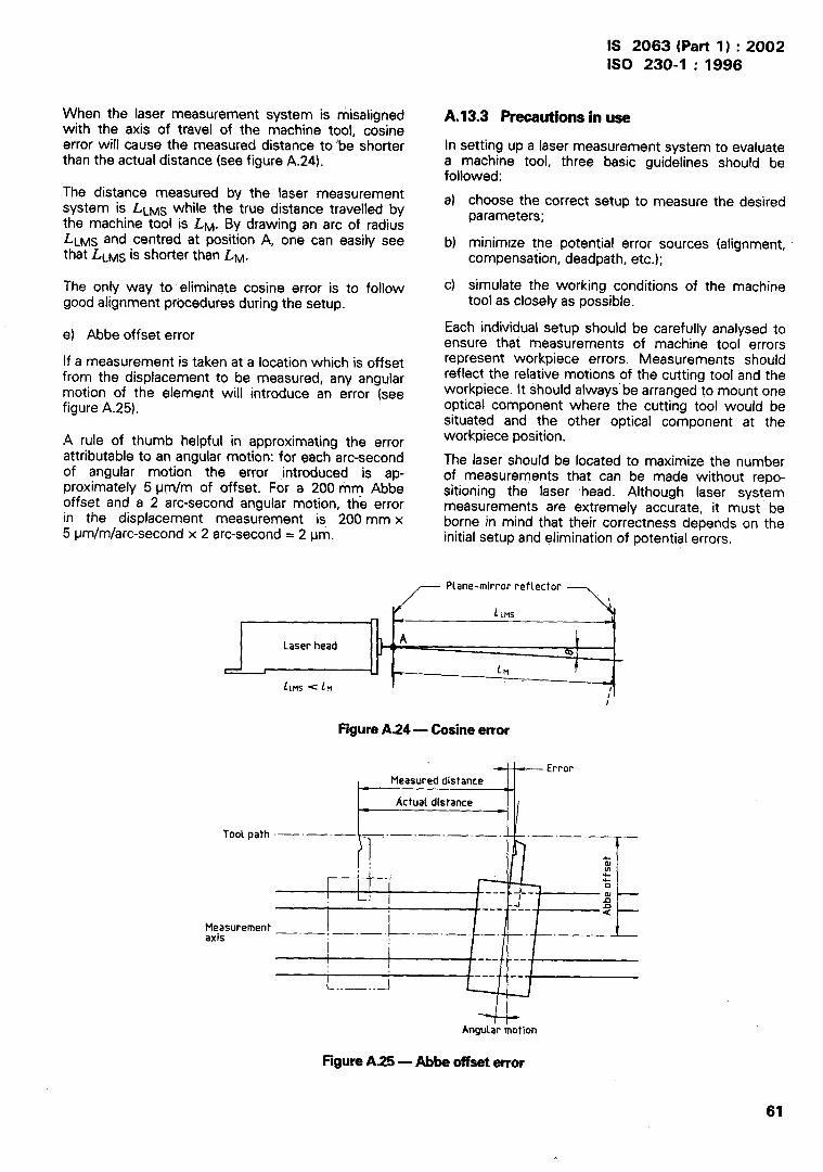
IS 2063 (Part 1) :2002ISO 230-1 :1996
When the laser measurementwith the axis of travel of the
system is misalignedmachine tool, cosine
error will cause the measured distance to ‘be shorterthan the actual distance (see figure A.24).
The distance measured by the laser measurementsystem is LLMS while the true distance travelled bythe machine tool is LM. By drawing an arc of radiusLLMS and centred at position A, one can easily seethat LLMS is shorter than LM.
The only way to eliminate cosine error is to followgood alignment procedures during the setup.
e) Abbe offset error
If a measurement is taken at a location which is offsetfrom the displacement to be measured, any angularmotion of the element will introduce an error (seefigure A.25).
.4 rule of thumb helpful in approximating the errorattributable to an angular motion: for each arc-secondof angular motion the error introduced is ap-proximately 5 pm/m of offset. For a 200 mm Abbeoffset and a 2 arc-second angular motion, the errorin the displacement measurement is 200 mm x5 ~mlmfarc-second x 2 arc-second = 2 pm.
I
-.
A.13.3 Precautionsin use
In setting up a laser measurement system to evaluatea machine tool, three basic guidelines should befollowed:
a) choose the correct setup to measure the desiredparameters;
b) minimize the potential error sources (alignment,compensation, deadpath, etc.);
c) simulate the working conditions of the machinetool as closely as possible.
Each individual setup should be carefully analysed toensure that measurements of machine tool errorsrepresent workpiece errors. Measurements shouldreflect the relative motions of the cutting tool and theworkpiece. It should always” be arranged to mount oneoptical component where the cutting tool would besituated and the other optical component at theworkpiece position.
The laser should be located to maximize the numberof, measurements that can be made without repo-.sRloning the laser head. Although laser systemmeasurements are extremely accurate, it must beborne in mind that their correctness depends on theinitial setup and elimination of potential errors.
Plane-mirror reflector7,
/ LCMS
\
r -l
Laser headA \
‘al
l-- 1 L [n !
LLMS < LM1’
FigureA.24 — Cosine error
F===T’rror
I
Tool path -—-—- -. —-—- —. —---
/l
II l-:
~ ? }T
z—. . . 2
) 0--- ---
J’ IIn------
L
a
Measurement —.— ,_ ._ . . .axis
1 I1
..- ---
L----- . --
..——..-1d
Angular motion
Figure A.25 — Abbe offset error
61

IS 2063 (Part l) :2002ISO 230-1 :1996
1
[1]
[21
[31
[41
[51
AnnexB(informative)
Bibliography
ISO 286-1:1988, ISO system of limits and fits —Part 1: Bases of tolerances, deviations and fits.
ISO 286:1991, Machine tools — Self-holding tapersfor tool shanks.
ISO 297:1988, 7/24 tapers for tool shanks formanual changing.
ISO 463:—s}, Geometrical product specification(GPS)— Dimensional measuring instruments: Dialgauges — Design and metrological requirements.
ISO 841 :-G), Industrial automation systems —Physical device control — Coordinate system andmotion nomenclature.
61
[71
[8)
[91
ISO 1101 :—7), Technical drawings — Geometrictolerancing — Tolerancing of form, orientation, lo-cation and run-out — Generalities, definitions,symbols, indications on drawings.
ISO 3650:-6), Geometrical product specification(GPS) — Length standards — Gauge blocks.
ISO 7368-1:1883, Tool shanks with 7/24 t~per forautomatic tool changers — Pan 1: ShanksNos. 40, 45 and 50 — Dimensions.
ISO 7388-2:1984, Tool shanks with 7/24 taper forautomatic tool changers — Part 2: Retentionknobs for shanks Nos. 40, 45 and 50 — Dimen-sions and mechanical characteristics.
5) To be published. (Revision of lSO/R 463:1965)
6) To be published. (Revision of ISO 841:1974)
7) To be published. (Revision of ISO 1101:1983)
8) To be published. (Revision of ISO 3650:1978)
62

Bureau of Indian Standards
.
I
I
1
BIS is a statutory institution established under the Bureau of Indian Standards Act, 1986 topromote harmonious development of the activities of standardization, marking and quality certificationof goods and attending to connected matters in the country.
Copyright
BIS has the copyright of all its publications. No part of these publications may be reprodued in anyform without the prior permission in writing from BIS. This does not preclude the free use, in thecourse of implementing the standard, of necessary details, such as symbols and sizes, type orgrade designations. Enquiries relating to copyright maybe addressed to the Director (Publications),BIS.
Review of Indian Standards
Amendments are issued to standards as the need arises on the basis of comments. Standardsare also reviewed periodically; a standard along with amendments is reaffirmed when such reviewindicates that no changes are needed; if the review indicates that changes are needed, it is takenup for revision. Users of Indian Standards should ascertain that they are in possession of the latestamendments or edition by referring to the latest issue of ‘BIS Catalogue’ and ‘Standards: MonthlyAdditions’.
This Indian Standard has been developed from Doc : No. BP 03 (0200),
Amendments Issued Since Publication
Amend No. Date of Issue Text Affected
BUREAU OF INDIAN STANDARDS
Headquarters :
Manak Bhavan, 9 Bahadur Shah Zafar Marg, New Delhi 110002 Telegrams : ManaksansthaTelephones : 32301 31, 3233375, 3239402 (Common to all offices)
Regional Offices : Telephone
Central :
Eastern :
Northern :
Southern :
Western :
Branches :
Manak Bhavan, 9 Bahadur Shah Zafar Marg{
32376 17NEW DELHI 110002 3233841
1/14 C.I.T. Scheme VI M, V. 1. P. Road, Kankurgachi
[
3378499, 3378561KOLKATA 700054 3378626, 33791 20
SCO 335-336, Sector 34-A, CHANDIGARH 160022
{
603843602025
C.I.T. Campus, IV Cross Road, CHENNAI 600 113
[
254 12 16, 254 144225425 19, 254 13 15
Manakalaya, E9 MlDC, Marol, Andheri (East)
[
8329295, 8327858MUMBAI 400093 8327891, 8927892
AHMEDABAD. BANGALORE, BHOPAL. BHUBANESHWAR. COIMBATORE. FARIDABAD.GHAZIABAD. GUWAHATI. HYDERABAD. JAIPUR. KANPUR. LUCKNOW. NAGPUR.NALAGARH , PATNA. PUNE. RAJKOT. TH IRUVANANTHAPURAM. VISAKHAPATNAM.
Printed by Dee Kay Printers.