ironman triad owner's manualdl.owneriq.net/c/c53802ee-e5f0-4524-9191-21c80ea828e7.pdf ·...
TRANSCRIPT

Owner’s ManualIronman TRIAD Treadmill
Service(800) 750-4766Assembly(888) 559-8810
Ironman Fitness Products4009 Distribution DriveSuite 250Garland, TX 75041
www.ironmanfitness.com
Model Name : TRIADSerial Number :Write down for future referenceSerial Number Decal Location
415-0001210/04
CAUTION! Read all precautions andinstructions in this manual beforeusing this equipment.

Table of Contents
2
Important Safety Information 3
Before You Start 4
Assembly 5-9
Moving Instructions 10
Power Requirements 11
Console Panel Functions 12
Program Operation 13-14
Program Profiles 15
Heart Rate Mode 16-17
Monitoring Your Heart Rate 18-19
Workout Information 20-21
Warm Up Exercises 22
Changing to MPH or KM 23
Calibration Sequence 24
Belt Adjustment 25
Maintenance Instructions 26
Error Messages 27
Troubleshooting 28
Parts List 29-30
Exploded View 31-32
Warranty Information 33

Important Safety Information
3
WARNING! Before using this treadmill or starting any exercise program, consult your physician. This is espe-cially important for persons over the age of 35 and/or persons with pre-existing health problems. The man-ufacturer or distributor assumes no responsibility for personal injury or property damage sustained by orthrough the use of this product.
WARNING! To reduce the risk of electrical shock, burns, fire, or other possible injuries to the user, it is impor-tant to review this manual and the following precautions before operation.
SAFETY PRECAUTIONS AND TIPS
1. It is the owner's responsibility to ensure that all users of this treadmill have read the Owner's Manual andare familiar with warnings and safety precautions.2. This treadmill has a user maximum capacity of 350 pounds.3. The treadmill should only be used on a level surface and is intended for indoor use only. The treadmillshould not be placed in a garage, patio, or near water and should never be used while you are wet. IronmanFitness recommends a treadmill mat be placed under the treadmill to protect floor or carpet and for easiercleaning.4. Follow safety information in regards to plugging in your treadmill. Keep the power cord away from theincline wheels and do not run the power cord underneath your treadmill. Do not operate the treadmill with adamaged or frayed power cord.5. Wear comfortable, good-quality walking or running shoes and appropriate clothing. Do not use the treadmillwith bare feet, sandals, socks or stockings.6. Always straddle the belt and allow it to start moving before stepping onto the belt.7. Hold on to handrail when adjusting speed, incline, or other controls.8. Always examine your treadmill before using to ensure all parts are in working order.9. Allow the belt to fully stop before dismounting.10. Pets should never be allowed near or on the treadmill.11. Do not leave children unsupervised near or on the treadmill.12. Never operate the treadmill where oxygen is being administered, or where aerosol products are being used.13. Never insert any object or body parts into any opening.14. For safety and to prevent damage to your treadmill, no more than one person should use the treadmill at atime.15. Always unplug the treadmill before cleaning and/or servicing. Service to your treadmill should only beperformed by an authorized service representative, unless authorized and/or instructed by the manufacturer.16. Failure to follow these instructions will void the treadmill warranty.17. Never leave the treadmill unattended while it is running.
Before You Start
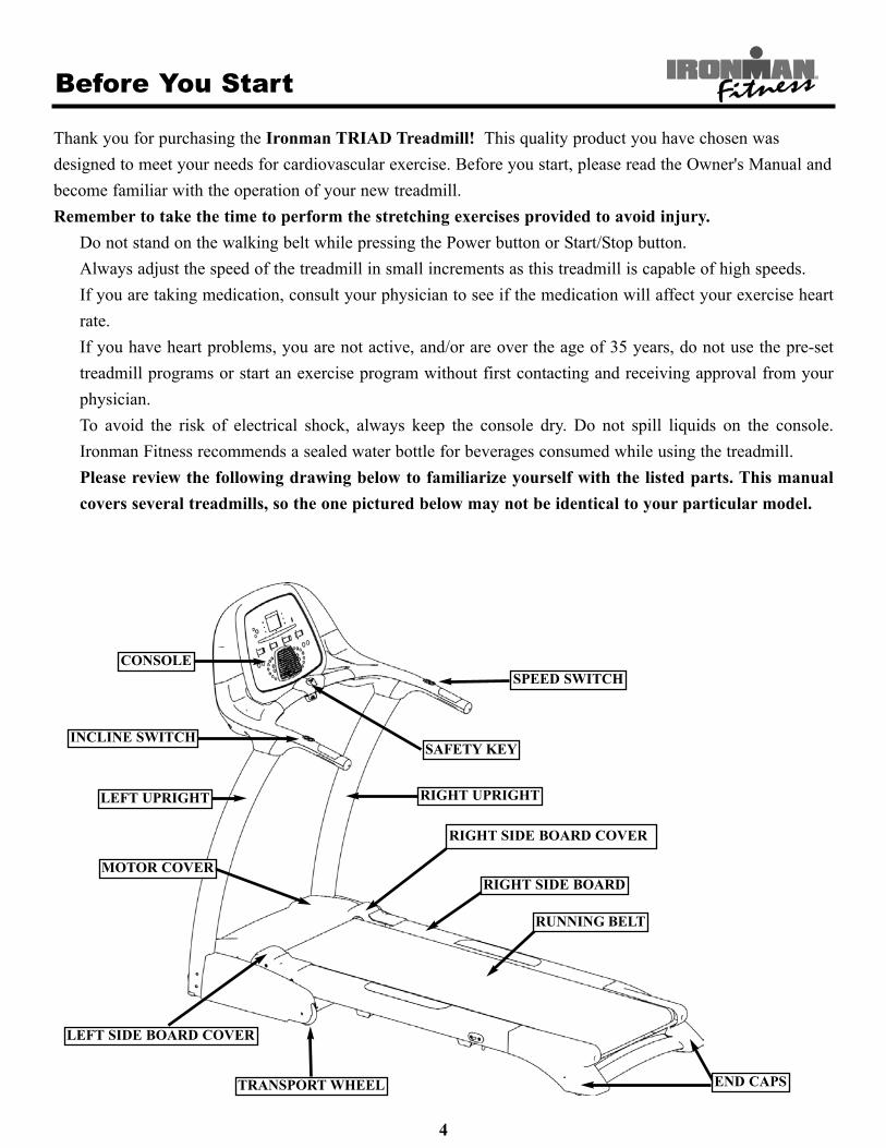
Thank you for purchasing the Ironman TRIAD Treadmill! This quality product you have chosen wasdesigned to meet your needs for cardiovascular exercise. Before you start, please read the Owner's Manual andbecome familiar with the operation of your new treadmill.Remember to take the time to perform the stretching exercises provided to avoid injury.
Do not stand on the walking belt while pressing the Power button or Start/Stop button.Always adjust the speed of the treadmill in small increments as this treadmill is capable of high speeds.If you are taking medication, consult your physician to see if the medication will affect your exercise heartrate.If you have heart problems, you are not active, and/or are over the age of 35 years, do not use the pre-settreadmill programs or start an exercise program without first contacting and receiving approval from yourphysician.To avoid the risk of electrical shock, always keep the console dry. Do not spill liquids on the console.Ironman Fitness recommends a sealed water bottle for beverages consumed while using the treadmill.Please review the following drawing below to familiarize yourself with the listed parts. This manualcovers several treadmills, so the one pictured below may not be identical to your particular model.
4
SAFETY KEY
RIGHT SIDE BOARD COVER
END CAPSTRANSPORT WHEEL
LEFT SIDE BOARD COVER
MOTOR COVER
LEFT UPRIGHT
INCLINE SWITCH
CONSOLESPEED SWITCH
RIGHT UPRIGHT
RIGHT SIDE BOARD
RUNNING BELT

Assembly
The Ironman TRIAD Treadmill will require assembly before operating. After opening the box, remove anypacking material from the treadmill.Do not throw away any packing materials until the unit is working properly.Place the base on a clean, level surface. Make sure the electrical cord will easily reach an electrical outlet.If at anytime you need assistance with assembly, call 888-559-8810.
Locate the hardware pack and identify the following parts required for assembly.
Tools:1. Allen Wrench- 3/16”2. Allen Wrench- 7/32”3. Philip Screwdriver
Main Components:1. Owner’s Manual2. Console Assembly3. Left and Right Uprights4. Left and Right Fender5. Left and Right Bottom Handle Cover6. Handle End Caps7. Deck Assembly8. Long Bumpers9. Chest Strap
Hardware:1. Washer 9*16*1.6 mm (Qty. 12)2. Spring Washer 8 mm (Qty. 12)3. Allen Bolt 5/16”-18 x 70 (Qty. 4)4. Allen Bolt 5/16”-18 x 15 (Qty. 6)5. Allen Bolt M8*30 (Qty. 2)6. Shoulder Allen Bolt 5/16”-18 x 45 (Qty. 2)7. Philip Screw ST4.2*16 (Qty. 8)
Wire Connections:1. Console Harness2. EKG Harness
5

Assembly
Assembly requires the included allen wrench and phillips screwdriver.
Do not plug in the power cord until all assembly steps are completed.
6
Figure 1: Console Harness Location
Figure 2: Console Harness Connection
1. With the treadmill deck in the downposition, leave the unit on the originalpacking material to assemble all parts.
Caution:Make sure harness is installed inside the upright and pay attention not to pinch the wire harness.
2. Connect the console harness together.One side of harness is located near themotor cover on the bottom left side. Theother end is located inside the LeftUpright assembly. See Figure 1 and 2.
3. Pull the wiring harness from top ofupright tube making sure harness connec-tors are pulled into large hole at bottomof upright.
CONSOLEHARNESS
Need Help With Assembly?Call (888) 559-8810

Assembly
7
Figure 3: Left and Right Upright Installation
Figure 4: Console Installation
4. Install the Left and Right Uprights to the tread-mill base frame by inserting the upright connect-ing bracket into base frame as seen in Figure 3,using Allen Bolt 5/16”-18 x 70 (Qty. 4), SpringWasher 8 mm (Qty. 4), and Washer 9*16*1.6 mm(Qty. 4).Next, install the Allen Bolt 5/16”-18 x 15 (Qty.6), Spring Washer 8 mm (Qty. 6), and Washer9*16*1.6 mm (Qty. 6). Refer to Figure 3.
Note: Do not tighten hardware in step 3 until step5 is completed.
IMPORTANT, PLEASE NOTE:While sliding the upright connecting bracket intothe base frame, make sure the harness isinstalled inside the upright and pay attentionnot to pinch the wire harness.
5. Connect the Console Harness together as shownin Figure 4. Wiring harness connectors snaptogether as shown in Figure 2.
Note: The upright console harness wire must beinserted through large hole at front side ofupright, before connecting to harness fromconsole assembly.
Connect the Console to the Left andRight Uprights by sliding the Consoleconnecting brackets into the end of the Left andRight Uprights as shown in Figure 4. Tighten intoplace using 5/16”-18x45 Shoulder Allen Bolt (Qty.2), Spring Washer 8 mm (Qty. 2), and Washer9*16*1.6 mm (Qty. 2).
IMPORTANT, PLEASE NOTE:While connecting the Console to the Left andRight Uprights, pay attention not to pinch the wireharness. Excess Console Harness wiring shouldbe placed inside the Left Upright, not ConsoleAssembly.
LEFT UPRIGHT
LEFT UPRIGHT
RIGHT UPRIGHT
RIGHT UPRIGHT
SPRING WASHER 8 mm
SPRING WASHER 8 mm
SPRING WASHER 8 mm
CONSOLEHARNESS
WASHER 9*16*1.6 mm
WASHER 9*16*1.6 mm
WASHER 9*16*1.6 mm
ALLEN BOLT5/16”- 18x70
ALLEN BOLT5/16”-18x15
CONSOLE
EKG HARNESS
SHOULDER ALLENBOLT 5/16”-18x45
Need Help With Assembly?Call (888) 559-8810

Assembly
8
6. Position the Left and Right Bottom HandleCovers to underside of handle assembly, thenconnect the EKG Harness Wires to the Left andRight Bottom Handle Pulse Plates as shown inFigure 5.Tighten into place using Philip Screw ST4.2X16(Qty. 6).Next, install the End Caps to the handle assem-bly.
IMPORTANT, PLEASE NOTE:Tighten all hardware installed in Step 1 throughStep 5.
7. Fold the treadmill into the storage position andlock into place as shown in Figure 6.
CONSOLE
PHILIP SCREWST4.2x16
END CAP
EKG HARNESS
LEFT BOTTOMHANDLE COVER
RIGHT BOTTOMHANDLE COVER
Figure 5: Left and Right Bottom Handle CoverInstallation
Figure 6: Storage Position Locking Method
LOCKEDUNLOCKED
Need Help With Assembly?Call (888) 559-8810

Congratulations! You have completed the assembly of your new Ironman TRIAD Treadmill!
Assembly
9
8. Remove the two Long Bumpers from base of treadmill as shown in Figure 7a. Install the Left and RightFender to Base using Philip Screw ST4.2X16 as shown in Figure 7b. Reinstall both Long Bumpers.
Figure 7b: Left and Right Fender InstallationFigure 7a: Long Bumper Removal
LEFT FENDER
BASE
PHILIP SCREWST4.2x16
RIGHT FENDERALLEN BOLT M8*30
LONG BUMPERBASE

Moving Instructions
10
CAUTION! TO AVOID THE RISK OF INJURY, NEVER ATTEMPT TO MOVE THE TREADMILLWHILE IT IS IN THE UNFOLDED OPERATING POSITION. TO REDUCE THE POSSIBILITY OFINJURY WHILE LIFTING, BEND YOUR LEGS AND KEEP YOUR BACK STRAIGHT. AS YOU RAISETHE TREADMILL, LIFT USING YOUR LEGS, NOT YOUR BACK. IN ORDER TO RAISE OR LOWERTHE TREADMILL SAFELY, YOU MUST BE ABLE TO LIFT 45 POUNDS (20KG). IT IS SUGGESTEDYOU ALWAYS USE THE AID OF A SECOND PERSON WHEN MOVING THE TREADMILL.
With the treadmill in the folded locked position (safety latch is engaged), grasp the handrail and place one footon the center of the base crossbar as shown in the photo below. Next, with a firm grasp on the handrail, care-fully tilt the treadmill back until it rolls freely on the wheels. Using extreme caution, move the treadmill to thedesired location. To set the treadmill down, place one foot on the center of the base crossbar and carefullylower treadmill onto base in resting position. Do not attempt to move the treadmill over an uneven or roughsurface.Note: The treadmill pictured below may not be identical to your particular model.

Power Requirements
11
IMPROPER CONNECTION OF THE EQUIPMENT GROUNDING CONNECTOR CAN RESULTIN A RISK OF AN ELECTRIC SHOCK. CHECK WITH A QUALIFIED ELECTRICIAN ORSERVICE MAN IF YOU ARE IN DOUBT AS TO WHETHER THE PRODUCT IS PROPERLYGROUNDED. DO NOT MODIFY THE PLUG PROVIDED WITH THE PRODUCT. IF PLUGWILL NOT FIT THE OUTLET, HAVE A PROPER OUTLET INSTALLED BY A QUALIFIEDELECTRICIAN.
This treadmill can be seriously damaged by sudden voltage changes in your home’s electrical power. Voltagespikes, surges, and noise interference can result from weather conditions or from other appliances being turnedon or off. To reduce the possibility of treadmill damage, always use a dedicated surge protector (not includ-ed) with your treadmill.
Surge protectors can be purchased at most hardware stores. The manufacturer recommends a single outletsurge protector with UL 1449 rating as a Transient Voltage Surge Suppressor (TVSS) with UL suppressedvoltage rating of 400V or less and an electrical rating of 120VAC, 15 amps.
This treadmill must be grounded to reduce the risk of electrical shock. Grounding provides a path of leastresistance for electric current should the treadmill malfunction. This treadmill comes with an electrical cordwith an equipment-grounding conductor and a grounding plug. Always plug the power cord into a surge pro-tector, and plug the surge protector into an appropriate outlet that is properly installed and grounded in accor-dance with all local codes and ordinances. Do not connect other equipment to the surge protector or this couldcause permanent damage to your treadmill.This product is for use on a nominal 120-volt circuit and has a grounding plug that looks like the plug illustrat-ed in the drawing below.
Console Panel Functions
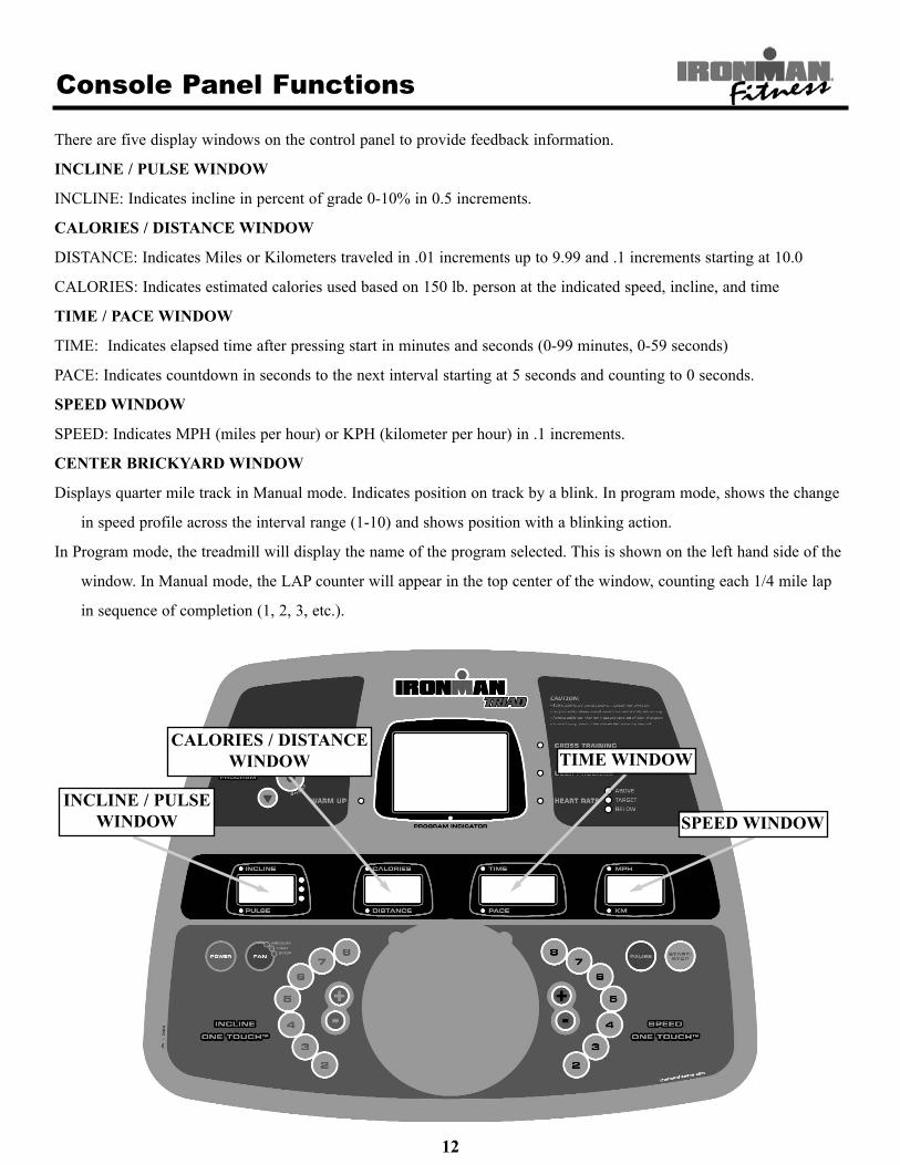
There are five display windows on the control panel to provide feedback information.
INCLINE / PULSE WINDOW
INCLINE: Indicates incline in percent of grade 0-10% in 0.5 increments.
CALORIES / DISTANCE WINDOW
DISTANCE: Indicates Miles or Kilometers traveled in .01 increments up to 9.99 and .1 increments starting at 10.0
CALORIES: Indicates estimated calories used based on 150 lb. person at the indicated speed, incline, and time
TIME / PACE WINDOW
TIME: Indicates elapsed time after pressing start in minutes and seconds (0-99 minutes, 0-59 seconds)
PACE: Indicates countdown in seconds to the next interval starting at 5 seconds and counting to 0 seconds.
SPEED WINDOW
SPEED: Indicates MPH (miles per hour) or KPH (kilometer per hour) in .1 increments.
CENTER BRICKYARD WINDOW
Displays quarter mile track in Manual mode. Indicates position on track by a blink. In program mode, shows the change
in speed profile across the interval range (1-10) and shows position with a blinking action.
In Program mode, the treadmill will display the name of the program selected. This is shown on the left hand side of the
window. In Manual mode, the LAP counter will appear in the top center of the window, counting each 1/4 mile lap
in sequence of completion (1, 2, 3, etc.).
12
SPEED WINDOW
TIME WINDOWCALORIES / DISTANCE
WINDOW
INCLINE / PULSEWINDOW
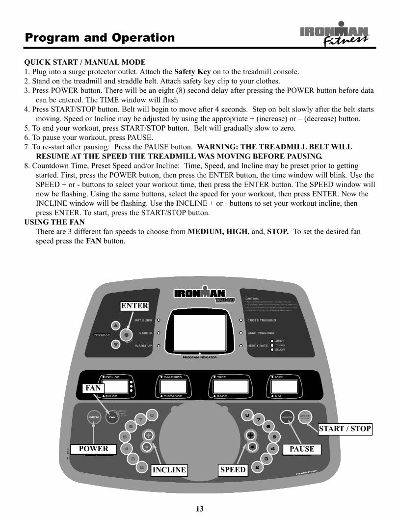
QUICK START / MANUAL MODE1. Plug into a surge protector outlet. Attach the Safety Key on to the treadmill console.2. Stand on the treadmill and straddle belt. Attach safety key clip to your clothes.3. Press POWER button. There will be an eight (8) second delay after pressing the POWER button before data
can be entered. The TIME window will flash.4. Press START/STOP button. Belt will begin to move after 4 seconds. Step on belt slowly after the belt starts
moving. Speed or Incline may be adjusted by using the appropriate + (increase) or – (decrease) button.5. To end your workout, press START/STOP button. Belt will gradually slow to zero.6. To pause your workout, press PAUSE.7 .To re-start after pausing: Press the PAUSE button. WARNING: THE TREADMILL BELT WILL
RESUME AT THE SPEED THE TREADMILL WAS MOVING BEFORE PAUSING.8. Countdown Time, Preset Speed and/or Incline: Time, Speed, and Incline may be preset prior to getting
started. First, press the POWER button, then press the ENTER button, the time window will blink. Use theSPEED + or - buttons to select your workout time, then press the ENTER button. The SPEED window willnow be flashing. Using the same buttons, select the speed for your workout, then press ENTER. Now theINCLINE window will be flashing. Use the INCLINE + or - buttons to set your workout incline, thenpress ENTER. To start, press the START/STOP button.
USING THE FANThere are 3 different fan speeds to choose from MEDIUM, HIGH, and, STOP. To set the desired fanspeed press the FAN button.
Program and Operation
13
POWER
INCLINE SPEED
FAN
ENTER
START / STOP
PAUSE

Program and Operation
PROGRAM MODEPlug treadmill into a surge protector outlet. Attach the Safety Key on to the treadmill console.1. Stand on the treadmill and straddle belt. Attach safety key clip to your clothes.2. Press POWER button. There will be an eight (8) second delay before data can be entered. The TIME window will
flash.3. There are four (4) pre-set and eight (8) semi-custom pre-set programs on the Ironman TRIAD. The treadmill
includes FAT BURN, CARDIO, WARM-UP, and CROSS TRAINING programs. Press the PROGRAM UP orDOWN button to select which program you wish to use. Press ENTER.
4. Press START/STOP button. Belt will begin to move after 4 seconds. Step on belt slowly after the belt starts moving.CUSTOMIZING PROGRAMS in P1 and P2 Mode:
Each pre-set program (Fat Burn, Cardio, and Warm-up) can be customized in the P1 or P2 mode. After making theprogram selection, the CAL / DIST window will read “OP”. The “OP” refers to “original program” and is preset.The program name you select will illuminate on the console display. Press the PROGRAM DOWN button oncemore and the CAL / DIST window will read P1. The “P1” mode is now accessed. You can now program the Time,Speed, and Incline in P1 mode, which will be saved for future workouts.
1) The TIME window will blink. Use the SPEED + or – buttons to select your workout time. Press ENTER PROGRAM.2) The SPEED window will then blink. Use the same + or – buttons to select the speed for your workout. Press ENTER
PROGRAM. 3) The INCLINE window will then blink. Use the INCLINE + or – buttons to set your workout incline. Press ENTER
PROGRAM. To start, press the START/STOP button. To access P2 mode, press the PROGRAM UP or DOWN button for desired
program, then press the ENTER button (once for OP, twice for P1, three times for P2). Follow the above steps 1-3 tocustomize P2 settings.
TO CHANGE A PREVIOUSLY PROGRAMMED P1, P2, or user program:Once you have programmed the P1 or P2 modes, you will need to use the PAUSE button to change the program youpreviously entered. For instance to change to a new setting in P1-FAT BURN, press the PROGRAM UP or DOWNto select the FAT BURN program. Next, press the same button once more to access P1. Then press the PAUSE but-ton to get the TIME window to flash. Follow the directions above to continue to change the program.
14
PAUSE
START / STOP
INCLINE SPEED
POWER
PROGRAMUP / DOWN
ENTER
Program Profiles
15
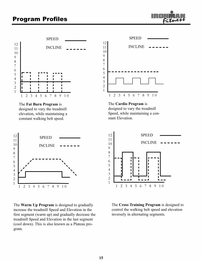
The Fat Burn Program isdesigned to vary the treadmillelevation, while maintaining aconstant walking belt speed.
The Cardio Program isdesigned to vary the treadmillSpeed, while maintaining a con-stant Elevation.
The Warm Up Program is designed to graduallyincrease the treadmill Speed and Elevation in thefirst segment (warm up) and gradually decrease thetreadmill Speed and Elevation in the last segment(cool down). This is also known as a Plateau pro-gram.
121110987654321
1 2 3 4 5 6 7 8 9 1 0
SPEED
INCLINE121110987654321
1 2 3 4 5 6 7 8 9 1 0
SPEED
INCLINE
121110987654321
1 2 3 4 5 6 7 8 9 1 0
SPEED
INCLINE
121110987654321
1 2 3 4 5 6 7 8 9 1 0
SPEED
INCLINE
The Cross Training Program is designed tocontrol the walking belt speed and elevationinversely in alternating segments.

HEART RATE MONITOR MODEThe treadmill may at any time be used in the Heart Rate Monitor Mode. If the signal from the chest strapis detected, heart rate BPM will be displayed in the INCLINE window. The incline will only be brieflydisplayed if manual or program changes are initiated. The Heart Rate program is designed to keep yourheart at a desired amount of “beats per minute” by automatically adjusting the incline. For example, youhave programmed in a desired heart rate of 125 BPM and your heart rate is only at 110 BPM. If you arewearing the Heart Rate Transmitter, correctly the incline will automatically increase to intensify the workload, causing your heart rate to slowly climb to 125 BPM. The treadmill will attempt to maintain your tar-get heart rate through adjustments to the incline for the remainder of your workout. In the same respect, ifyour heart rate is above your programmed amount of BPM’s, the incline will automatically decrease tolower your heart rate. You may at any time during the Heart Rate Program adjust/override the speedand/or the incline by simply pressing the correct corresponding button. You may also change your “TargetHeart Rate” at any time by pressing the PROGRAM UP or PROGRAM DOWN button.
HEART RATE PROGRAM OPERATION1. Plug treadmill into a surge protector outlet. Attach the Red Safety Key on to the treadmill console.2. Stand on the treadmill and straddle belt. Attach safety key clip to your clothes.3. Press POWER button. Place the Heart Rate Transmitter strap across your chest and connect ends. (Make
sure your skin is moist and the strap is snug for accurate transmission). At this time, if the display isreceiving a signal from the chest strap, the incline window will begin to settle on your current heart rate.
4. Press the PROGRAM UP button until the HEART RATE LED is on. The incline window will momentarilyflash ‘125’, which is the default program target heart rate.
5. The TIME/PACE window will blink. Use the + or - arrows to select your workout time. Press ENTERPROGRAM.
6. The SPEED window will then blink. Use the + or - arrows to select the speed for your workout. PressENTER PROGRAM.
7. The incline window (if receiving your heart rate accurately) will show current BPM, and the small red lightlabeled PULSE adjacent to the incline window, will be illuminated. (If the receiver is not receiving anaccurate reading, the incline window will be flashing - - - -).
8. To adjust the pre-set target heart rate press the PROGRAM UP or PROGRAM DOWN button then pressthe ENTER PROGRAM button.
9. Press START/STOP button. Belt will begin to move after 4 seconds. Step on belt slowly after the belt startsmoving.
10. Press START/STOP button. Belt will begin to move after 4 seconds. Step on belt slowly after the beltstarts moving.The small light on the console labeled TARGET will be illuminated if you are at your target. If you arenot, the ABOVE or BELOW lights will illuminate and reflect if you are above or below your goal. If youare not within 25 BPM of your “Target heart rate” the program will not work. DO NOT STOP TO STARTOVER. Continue exercising and your heart rate will naturally increase. The program will continuallymonitor your heart rate and periodically adjust the incline up or down to increase or decrease the resistancethereby keeping you at your target zone. At the conclusion of the programmed time the TIME windowwill flash 00:00 and the CALORIES/DISTANCE window will continue to accumulate values. The tread-mill will continue operation until the START/STOP button or the PAUSE button is pressed. Press thePOWER button to turn off the treadmill.
Program Instructions: Heart Rate Mode
16

Program Instructions: Heart Rate Mode
17
START / STOP
INCLINE SPEED
POWER
TARGET LED’S
PAUSE
HEART RATE LED

Monitoring Your Heart Rate
18
Monitoring Your Heart Rate
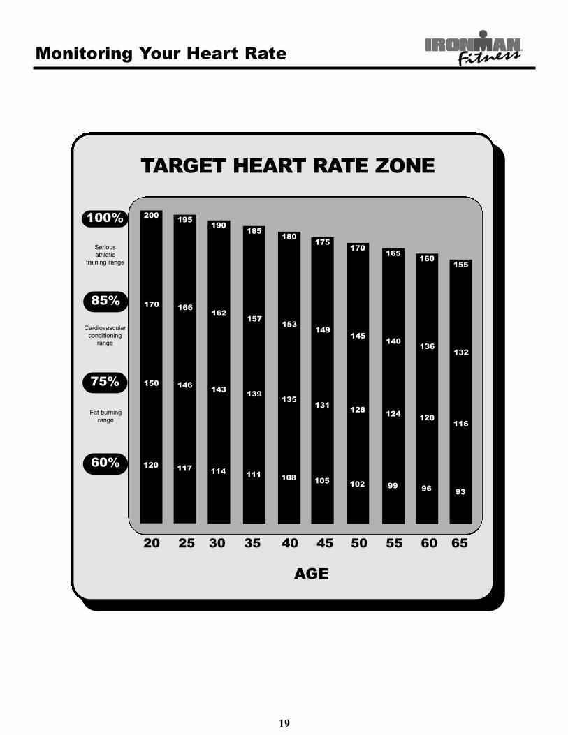
To obtain the greatest cardiovascular benefits from your exercise workout, it is important to work within yourtarget heart rate zone. The American Heart Association (AHA) defines this target as 60%-75% percent of yourmaximum heart rate.
Your maximum heart rate may be roughly calculated by subtracting your age from 220. Your maximum heartrate and aerobic capacity naturally decreases as you age. This may vary from one person to another, but usethis number to find your approximate effective target zone. For example, the maximum heart rate for an aver-age 40 year-old is 180 bpm. The target heart rate zone is 60%-75% of 180 or 108-135 bpm. See Fitness Safetybelow.
Before beginning your workout, check your normal resting heart rate. Place your fingers lightly against yourneck, or against your wrist over the main artery. After finding your pulse, count the number of beats in 10 sec-onds. Multiply the number of beats by six to determine your pulse rate per minute. We recommend taking yourheart rate at these times; at rest, after warming up, during your workout and two minutes into your cool down,to accurately track your progress as it relates to better fitness.
During your first several months of exercising, the AHA recommends aiming for the lower part of the targetheart rate zone-60%, then gradually progressing up to 75%.According to the AHA, exercising above 75% of your maximum heart rate may be too strenuous unless youare in top physical condition. Exercising below 60% of your maximum will result in minimal cardiovascularconditioning.
Check your pulse recovery rate – If your pulse is over 100 bpm five minutes after you stop exercising, or ifit’s higher than normal the morning after exercising, your exertion may have been too strenuous for your cur-rent fitness level. Rest and reduce the intensity next time.
Fitness Safety The target heart rate chart indicates average rate zones for different ages. A variety of differentfactors (including medication, emotional state, temperature and other conditions) can affect the target heartrate zone that is best for you. Your physician or health care professional can help you determine the exerciseintensity that is appropriate for your age and condition.
(MHR) = Maximum Heart Rate(THR) = Target Heart Rate
220 - age = maximum heart rate (MHR)MHR x .60 = 60% of your maximum heart rate. MHR x .75 = 75% of your maximum heart rate.
For example, if you are 30 years old, your calculations will be as follows:220 - 30 = 190190 x .60 = 114 (low end or 60% of MHR)190 x .75 = 142 (high end or 75% of MHR)30 year-old (THR) Target Heart Rate would be 114-142
See Heart Rate Table (on next page) for additional calculations.
Monitoring Your Heart Rate
19
100%
85%
75%
60%
Serious athletic
training range
Cardiovascular conditioning
range
Fat burningrange
20 25 30 35 40 45 50 55 60 65
AGE
200 195190
185180
175170
165 160155
170 166162
157153
149145
140 136132
150 146 143 139135
131 128 124 120116
120 117 114 111 108 105 102 99 96 93
TARGET HEART RATE ZONE
Workout Information
20
Frequency, Intensity, Time, Target Heart Rate Zone
The exercise practices include four major variables: frequency, intensity, time, target heart rate zone. A contin-uous workout will help to improve your cardiovascular functions and increase the ability of your muscles toobtain the oxygen and nutrition. A good workout provides a greater advantage to extend the endurance of mus-cle and body flexibility.
Frequency: How Often Should You Exercise
Three to five times a week is highly suggested to improve your cardiovascular and muscle fitness.
Intensity: How Hard Should You Exercise
The intensity of an exercise is reflected in your heart rate. Exercise must be sufficient to strengthen your heartmuscle and condition your cardiovascular system. Only your doctor or an authorized coach can prescribe thetarget training heart range appropriate for your particular needs and physical condition.Start with exercise that stimulates you to breathe more deeply. Alternate periods of moderate and easy exerciseto help your body adapt to new levels of exertion without unnecessary strain. The inability to maintain a smooth,rhythmic motion is a sign that you speeded and/or elevated too high. If you feel out of breath before you haveexercised 12 minutes, you are probably overdoing it.
As your fitness level improves, you will need to increase your workload to reach your target heart rate. Thefirst increase may be necessary after two to four weeks of regular exercise. Never exceed your target heart ratezone.
Weight Management
Consistent aerobic exercise will help you change your body composition by lowering your percentage of bodyfat. For weight control, how long and how often you exercise is more important than how hard you exercise. Exercise at least four to five times a week. Reach and maintain 60-75% of your maximum heart rate with moderate exercise. Exercise for 30-45 minutes at 60-65% of your target heart rate.
Here are some tips to achieve your weight management goal. Consume most of your dietary calories at breakfast and lunch, and eat a light dinner. Do not eat anything near the bedtime. Moderate exercise will help suppress your appetite. Take regular breaks and rests to help increase metabolism.
Warning!If you have any questions or concerns about your target heart rate consult your physician
Medications may affect your heart rate. Stop exercise if: you feel faint or dizzy, acute illness (cold or fever),any pain or tightness in your chest, an irregular heartbeat, of if you exceed your maximum heart rate set byyour physician.

Workout Information
21
Exercise Practice Procedures
Warm-Up Workout Cool Down
A good warm-up will help you perform better and will decrease the aches and pains. The warm-up preparesyour muscles for exercise and allows your oxygen supply to ready itself for what is to come. Experience tellsus that muscles perform best when they are warmer than normal body temperature. This normally takes about5-10 minutes when you begin to perspire on your brow and breathe more deeply.
Note: The older you are, the longer your warm-up period should be.
Workout: Brisk and Rhythmic Exercise
A workout trains your heart, lungs, and muscles to be more efficient. Increase exercise in response to your heartrate to train and strengthen your cardiovascular system. Concentrate on moving your arms and legs smoothly.Walking naturally and avoid jerking motions like pulled muscles, sprained joints, and loss of balance.
If you cannot sustain 12 continuous minutes in your target heart rate zone, then, exercise several times a day toget into habit. Try to reach and maintain 60-65% of your maximum heart rate. Alternate exercise with periodsof rest until you can sustain 12 continuous minutes of exercise at 60-65% of your maximum heart rate. Best startwith a target 3-4 minutes, then, increase it gradually.
If you can sustain 12 but not 20 continuous minutes of exercise in your target heart rate zone:Exercise 3-5 days a week. Rest at least two days per week.Try to reach and maintain 65-70% of your maximum heart rate with moderate rhythmic exercises.Begin with 12 continuous minutes. Increase your time by one to two minutes per week until you can sustain 20continuous minutes.
If you can sustain 20 minutes continuously in your target heart rate zone, begin to increase the length and inten-sity of your workout.Exercise 4-6 days a week or on alternate days.Try to reach and maintain 70~85% of your maximum heart rate with moderate to somewhat hard exercise.Exercise 20-30 minutes.
WARNING: These strategies are intended for average healthy adults. If you have pain or tightness in yourchest, an irregular heartbeat, shortness of breath or you feel faint or have any discomfort when you exerciseSTOP. Consult your physician before continuing. Remember every workout should begin with warm-up andfinished with cool-down.
Cool down: Slow and Relaxed Exercise
The cool-down allows your body’s cardiovascular system to gradually return to normal and should be roughly5-10 minutes. Lower your exercise intensity gradually, and when your heart rate has returned below 110 beatsper minutes, you can end your workout.

Warm Up Exercises
22
TOE TOUCH STRETCHStand, bending your knees slightly and slowly bend forward from your hips.Allow your back and shoulders to relax as you reach down toward your toesas far as possible. Hold for 15 counts, then relax. This will stretch your ham-strings, back of knees, and back.
HAMSTRING STRETCHSit with one leg extended. Bring the sole of the opposite foot toward you andrest it against the inner thigh of your extended leg. Reach toward your toes asfar as possible. Hold for 15 counts, then relax. This will stretch your ham-strings, lower back, and groin.
CALF/ACHILLES STRETCHWith one leg in front of the other, reach forward and place your hands againsta wall. Keep your back leg straight and your back foot flat on the floor. Bendyour front leg, lean forward and move your hips toward the wall. Hold for 15counts, then relax. To cause further stretching of the Achilles tendon, bendyour back leg as well. This will stretch your calves, Achilles tendons, andankles.
QUADRICEPS STRETCHWith one hand against a wall for balance, reach back and grasp one foot withyour other hand. Bring your heel as close to your buttocks as possible. Holdfor 15 counts, then relax. This will stretch your quadriceps and hip muscles.
INNER THIGH STRETCHSit with the soles of your feet together and your knees outward. Pull yourfeet toward your groin area as far as possible. Hold for 15 counts, then relax.This will stretch your quadriceps and hip muscles.
EXERCISE GUIDELINES
WARNING! Before beginning this or any exercise program, you should consult your physician. This is espe-cially important for individuals over the age of 35 or individuals with pre-existing health problems.
Warming up prepares the body for the exercise by increasing circulation, supplying more oxygen to the mus-cles and raising body temperature. Begin each workout with 5 to 10 minutes of stretching and light exerciseto warm up. The photos on this page show several forms of basic stretching you may perform before yourworkouts. In order to achieve an adequate warm-up, perform each stretch three times.

Change to MPH or KPH
23
Your treadmill will operate in British Units (miles per hour) or International Units (kilometers per hour). Alltreadmills are calibrated at the factory for British Units (miles per hour). To change the display to read in kilo-meters, follow the steps described here:
1) Turn power OFF on the console. (Do not unplug treadmill.) Attach the magnet safety key to the console.
2) Activate the calibration mode switch by inserting the eraser end of a pencil into the opening in the backsideof the console (see diagram below).
3) Depress the calibration mode switch ONCE. CL11 should appear in the TIME window.
4) Pressing the SPEED +/- button will activate your choice.
5) To accept the setting, press the POWER button.

Calibration Sequence
24
Do not attempt to calibrate the treadmill unless an Error Code is present. See Error Messages (page 27).Our treadmill is equipped with a software package that will perform a calibration sequence unique to yourspecific model number.Please perform the following steps to calibrate the Ironman TRIAD Treadmill.1. Unplug power cord from outlet strip.2. Attach Safety Key to console.3. Plug power cord into outlet strip.4. Initiate calibration sequence. Locate the hole on the back of the console and insert the eraser end of a pencilthrough the hole and press the calibration switch twice. As show on page 23.5. CL21 should appear in the Time window, if not, continue to press the calibration switch until CL21appears.Note: During the calibration sequence, the Time window will display which step you are at in the process(C21, C22, C23 and so on). The CAL/DIST window will display which key should be pressed next. Forexample, “E” for Enter, “P” for Power, or “SS” for Start / Stop.6. CL21: MPH or KPH will be flashing in the Speed window, pressing the Speed +/ - button will toggleoptions. Choose MPH (KPH), press Enter.7. CL22: 8, 10, or 12 (13, 16, or 20 in KPH mode) will be displayed in the Speed window, pressing the Speed+/ - button will toggle options. Choose 10 (or 16 for KPH mode), press Enter.8. CL23: FFF, UUU, or HHH will be displayed in the Speed window, pressing the Speed +/ - button will tog-gle options. Choose UUU, press Enter.9. CL24: 111 or 222 will be displayed in the Speed window, pressing the Speed +/ - button will toggleoptions. Choose 222, press Enter.10. CL25: “---” will be displayed in the Speed window, press Enter.11. CL26: OPA or OPI will be displayed in the Speed window, pressing the Speed +/ - button will toggleoptions. Choose OPA, press Enter.12. CL27: Blank (nothing), “a”, “b”, “c”, “d” or “e” will be displayed in the Incline window, pressing theSpeed +/ - button will toggle options. Choose “a”, press Enter.13. CAL/DIST window will display “55”. Press Start / Stop. “E” will display in CAL/DIST window.14. At this time, make sure you are not standing on the walking belt, as the machine will automatically initiatebelt movement and run through a complete calibration and diagnostic routine.Press Enter. Belt will begin to move. Unit will begin self-calibration.15. When Speed and Incline calibration has finished, press Power button twice, display should be blank, andtreadmill should be ready for use.To avoid possible damage to the treadmill and the possibility of injury, do not operate the treadmilluntil the problem is corrected. Call Ironman Fitness Customer Service at (800) 750-4766 if problem per-sists.

Belt Adjustment
25
WARNING! Do not over-tighten rollers! This will cause prema-ture roller bearing failure! Belt adjustment and tension performs two functions: adjustment fortension and centering. Your new treadmill comes pre-adjusted fromthe factory for tension and centering. Please follow the proceduresbelow if the belt shifts to the left or right while walking:WALKING BELT IS SHIFTING TO THE LEFT (Diagram 1)First, turn treadmill on to run at 1 mph. Using the hex key provid-ed, turn the left rear roller adjustment bolt ¼ turn in the clockwisedirection. Next, run the treadmill at 2.5 mph. You should see the beltstart to correct itself by moving back toward the center. Repeat theabove procedure until the walking belt is centered. It may be neces-sary to set walking belt tension once you have completed this proce-dure if the belt feels like it is slipping while walking. Refer below tothe “Walking Belt Slipping” instructions.
WALKING BELT IS SHIFTING TO THE RIGHT (Diagram 2)First, turn the treadmill on to run at 1 mph. Using the hex key pro-vided, turn the right rear roller adjustment bolt ¼ turn in the clock-wise direction. Next, run the treadmill at 2.5 mph. You should seethe belt start to correct itself, moving back toward the center. Repeatthe above procedure until the walking belt is centered. It may benecessary to set walking belt tension once you have completed thisprocedure if the belt feels like it is slipping while walking. Referbelow to the “Walking Belt Slipping” instructions.
WALKING BELT IS SLIPPING DURING USE (Diagram 3)First, unplug the power cord from the surge protector. Using the hexkey provided, turn both left and right rear roller adjustment bolts thesame distance, usually a ¼ turn, in the clockwise direction. Plug thepower cord back into the surge protector and run the treadmill at 2.5mph. You should now walk on the belt to determine if the belt is stillslipping. Repeat the above procedure until the walking belt is notslipping. The tension should be just tight enough not to slip.
Note: Turning the hex key counter clockwise brings the rearrollers and belt towards you.Turning the hex key clockwise pushes the rear roller and beltaway from you.
Diagram 1
Diagram 2
Diagram 3

Maintenance Instructions
26
WARNING! Before performing any maintenance to your treadmill, always unplug the power cord fromthe surge protector.
CLEANING: Routine cleaning of your unit will extend the life of your unit. WARNING! To prevent electrical shock, be sure the power to the treadmill is OFF and the unit is unpluggedfrom the wall electrical outlet before attempting any cleaning or maintenance.AFTER EACH WORKOUT: Wipe off the console and other treadmill surfaces with a clean, water damp-ened soft cloth to remove excess perspiration. USE NO CHEMICALS.WEEKLY: Use of a treadmill mat is recommended for ease of cleaning. Dirt from your shoes contacts thebelt and eventually makes it to underneath the treadmill. Vacuum underneath treadmill once a week.DECK LUBRICATION: The walking belt has been pre-lubricated at the factory. However, it is recommend-ed that the walking board be checked periodically for lubrication to ensure optimal treadmill performance.Every 30 days or 30 hours of operation, lift the sides of the walking belt and feel the top surface of the walk-ing board as far under as you can reach. If you feel signs of silicone, no further lubrication is required. If itfeels dry to the touch, lubrication is needed. Ironman Fitness recommends “Lube N Walk” for cleaning andlubricating the treadmill belt and deck. Ask your retailer or call Ironman Fitness at (800) 750-4766. You mayalso use silicone such as “Napa 8300” (available at most NAPA Auto Parts stores).TO APPLY LUBRICANT TO THE WALKING BOARD1) Position the walking belt so that the seam is located on top and in the center of the center of the walkingboard.2) Insert the spray nozzle into the spray head of the lubricant can.3) While lifting the side of the walking belt, position the spray nozzle between the walking belt and the boardapproximately 6” from the front of the treadmill. Apply the silicone spray to the walking board, moving fromthe front of the treadmill to the rear. Repeat this on the other side of the belt. Spray approximately 4 secondson each side.4) Allow the silicone to ‘set’ for one minute before using the treadmill.
WARNING: Do not over-lubricate the walking board. Excess lubricant should be wiped off with a cleantowel.

Error Messages
27
Treadmill Error Messages.
Your treadmill is equipped with a software package that enables error messages to be displayed when there isa problem. The following error codes will be displayed in the console display windows.
Safety Interlock Error MessagesSI 1 - Safety key missing, replace and try again.SI 2 - Over voltage protection trip. Notify Ironman Fitness Customer Service.
Other Error MessagesE11 - Lack of speed feedback data from belt motor. Attempt calibration. See Calibration Sequence section onpage 24 of this Owners Manual for detailed information.E22 - Under Speed condition detected from the belt motor. Attempt calibration. See Calibration Sequence sec-tion for detailed information.E33 - Over Speed condition detected from the belt motor. Attempt calibration. See Calibration Sequence sec-tion for detailed information.E44 - Stuck key detected at power up, Notify Ironman Fitness Customer Service.
To avoid possible damage to the treadmill and the possibility of injury, do not operate the treadmilluntil the problem is corrected. Call Ironman Fitness Customer Service at (800) 750-4766.

Troubleshooting Guide
28
Treadmill will not start.1. Is the Safety Key inserted into the treadmill Console?2. Make sure the power cord is plugged into a surge protector, the surge protector is plugged into a properly
grounded outlet, and the surge protector is turned on. (Refer to “Power Requirements” on page 11.)3. Check the circuit breaker located on the front of the treadmill. If the switch protrudes, it has tripped. Wait
five minutes and then press the switch back in.4. Check the house electrical breaker box and the circuit breaker for the room where the treadmill is located.
If it has tripped, reset or have an electrician replace the breaker in home.5. Have an electrician check to insure there is adequate voltage at the outlet.
Treadmill loses power during use.1. Check the circuit breaker located on the front of the treadmill. If the switch protrudes, it has tripped. Wait
five minutes and then press the switch back in.2. Check the house electrical breaker box and the circuit breaker for the room where the treadmill is located.
If it has tripped, reset or have an electrician replace the breaker in home.3. If the treadmill will not operate, please call Ironman Fitness Customer Service at (800) 750-4766.
Treadmill walking belt slows during use.1. Check to make sure the treadmill is securely plugged into an UL-listed surge protector, rated at 15 amps,
with a 14-gauge cord of five feet or less and the surge protector is securely plugged into the outlet.2. If treadmill will not operate, please call Ironman Fitness Customer Service at (800) 750-4766.
Treadmill walking belt slips or is not centered on rear roller.1. Refer to “Belt Adjustment” section on page 25.2. Need help? Call Ironman Fitness Customer Service at (800) 750-4766.
Treadmill Error Messages.Your treadmill is equipped with a software package that enables error messages to be displayed when there isa problem.To avoid possible damage to the treadmill and the possibility of injury, do not operate the treadmilluntil the problem is corrected. Call Ironman Fitness Customer Service at (800) 750-4766, or see “ErrorMessages” on page 27 of this Owner’s Manual.

Parts List
29
REF# KEYS PART# DESCRIPTION QTY. REF# KEYS PART# DESCRIPTION QTY.
1 423-00008 Cross Bar 1 54 402-00046 Clip Nut 8
2 406-00055 Base Bumper 2 55 406-00034 Transport Wheel 2
3 406-00056 Long Bumper 2 56 404-00004 Poly V-Belt 190J8 1
4 423-00009 Left Upright 1 57 404-00006 Running Belt 1
5 423-00010 Right Upright 1 58 403-00005 Deck Board 1
6 423-00011 Deck Frame 1 59 406-00035 Deck Bumper 7
7 423-00012 Base 1 60 410-00014 Allen Wrench Hanger 1
8 419-00007 Elevation Frame 1 61 406-00045 Adjust Support 2
9 419-00008 Motor Frame 1 62 409-00003 Front Roller 1
10 405-00008 Side Board-Latch Side 1 63 409-00004 Rear Roller 1
11 405-00009 Side Board-Right 1 64 410-00019 Gas Spring 1
12 419-00010 Linkage Bracket 2 65 419-00012 Rear Wheel Shaft 4
13 419-00009 Reed Switch Plate 1 66 402-00051 Shoulder Allen Bolt 1/4"-20 x63.5mm 2
14 419-00011 Side Motor Cover Bracket 2 67 402-00052 Shoulder Allen Bolt 1/4"-20 x28.5mm 2
15 410-00015 Power Cord Bracket 1 68 402-00053 Shoulder Allen Bolt 5/16"-18 x45mm 4
16 410-00016 Belt Guide Bracket- Board Mounted 2 69 402-00054 Allen Bolt 5/16"-18 x15mm 6
17 410-00012 Latch Pin 1 70 402-00055 Allen Bolt 5/16"-18 x70mm 4
18 410-00013 Latch Guide Plate 2 71 402-00056 Carriage Bolt 5/16"-18 x25.4mm 9
19 406-00036 Motor Cover 1 72 402-00057 Carriage Bolt 5/16"-18 x19mm 4
20 406-00037 Left Fender 1 73 402-00058 Nylon Lock Nut 5/16"-18x8.9mm 9
21 406-00038 Right Fender 1 74 402-00059 Hex Bolt 3/8"-16x45mm 1
22 406-00039 Left End Cap 1 75 402-00060 Hex Bolt 3/8"-16x63.5mm 1
23 406-00040 Right End Cap 1 76 402-00061 Allen Bolt 3/8"-16x40 2
24 406-00048 Molded Rear Pan 1 77 402-00062 Nylon Lock Nut 3/8"-16x11.5mm 2
25 406-00049 Front Bottom Pan 1 78 402-00063 Nylon Lock Nut 5/16"-18 x8.9mm 2
26 406-00050 Rear Bottom Pan 1 79 402-00047 Jam Nut 5/16"-18 4
27 406-00094 Bottom Sheet 1 80 402-00064 Screw ST4.2x32 2
28 406-00021 Main Console Box (B) 1 81 402-00065 Screw ST4.8x16 6
29 406-00022 Left Top Handle Cover 1 82 406-00095 Square Bumper 2
30 406-00023 Right Top Handle Cover 1 83 402-00118 Philip Screw ST4x16 19
31 406-00024 Left Pocket Bottom 1 84 402-00068 Philip Screw ST4.2x16 66
32 406-00025 Right Pocket Bottom 1 85 402-00069 Philip Screw ST2.9x9.5 15
33 406-00026 Left Bottom Handle Cover 1 86 402-00119 Philip Screw 10-24" x42.5mm 2
34 406-00027 Right Bottom Handle Cover 1 87 402-00071 Chamfer Bolt 1/4"-20 x 25mm 8
35 406-00028 Reed switch Top Holder 1 88 402-00072 Nylon Lock Nut 1/4"-20 x 6.5mm 8
36 406-00029 Reed switch Bottom Holder 1 89 402-00073 Washer 6.6x12x1.6mm 4
37 406-00054 Console B Insert for 5 Wind LED 1 90 402-00074 Washer 9x16x1.6mm 17
38 402-00090 Kill switch magnet 1 91 402-00075 Spring Washer 8mm 16
39 414-00014 Anti -Skid Pads 2 92 410-00020 Pulse Receptacle Plate-Top 2
40 406-00030 Fan Grill 1 93 410-00021 Pulse Receptacle Plate-Bottom 2
41 406-00032 Fan Motor Mount 1 94 402-00076 Philip Screw ST4.2x9.6 4
42 402-00091 Plastic Washer 2 95 402-00077 Philip Screw M2.5x6 2
43 402-00049 Clip Nut 3 96 402-00078 Washer 2.5x5x0.5mm 2
44 405-00004 T Extrusion 1 97 402-00079 Spring Washer 2.5mm 2
45 405-00005 S Extrusion 2 98 402-00080 Gear Washer D2.5 2
46 406-00041 Plug Calibration hole 1 99 402-00048 Pan Spring Washer 10x19x0.25mm 6
47 406-00033 Dome End cap 35mm 2 100 410-00022 Wrench 6x117mm 1
48 406-00047 Console Fan 1 101 410-00023 Allen Wrench 3/16" 1
49 406-00042 Left Sideboard Cover 1 102 410-00024 Allen Wrench 7/32" 1
50 406-00043 Right Sideboard Cover 1 103 410-00025 Glue 2mg
51 410-00018 Latch Guide 1 104 406-00096 Base Bumper 1
52 406-00044 Rear Wheel 4 105 410-00027 Bolt Glue 4g
53 402-00050 Powder Metal Bushing 9 106 410-00028 Silicone 30g
Ironman TRIAD Treadmill Parts List

Parts List
30
REF# KEYS PART# DESCRIPTION QTY. REF# KEYS PART# DESCRIPTION QTY.
107 410-00029 Double Adhesive 4 137 408-00016 Transformer (With Fan) 1
108 410-00030 Double Adhesive 1 138 413-00018 Fan Harness 1
109 410-00031 Adhesive Tape 1 139 407-00007 Motor Controller 1
110 410-00032 Double Adhesive 1 140 407-00008 EKG Module 1
111 410-00033 Loincloth Base 12 141 413-00019 Tel-line 1
112 410-00034 Loincloth 4 142 407-00006 Speed Incline PCB 2
113 410-00035 Loincloth 15 143 414-00022 Overlay TRIAD 1
114 402-00081 Plastic Washer 18 144 407-00010 5 Window LED PCB 1
115 402-00082 Washer 9x22x2mm 4 145 408-00018 Membrane Speed 1
116 402-00120 Philip Screw ST4.2x9.5 4 146 408-00019 Membrane Incline 1
117 402-00031 Philip Screw ST4.2x13 3 147 408-00020 Membrane Program 1
118 402-00085 Philip Screw 10-24" x12mm 1 148 412-00005 Actuator 1
119 408-00013 Speed Sensor 1 149 415-00012 Manual TRIAD 1
120 413-00012 Encoder Harness 1 150 402-00092 Allen Bolt 2
121 412-00004 Motor 1 151 406-00057 Power Cord Spacer 1
122 406-00046 Fan (motor) 1 152 402-00093 Gear Washer 1
123 413-00013 Console Harness 3pcs 153 402-00095 Washer 2
124 413-00014 SPD and INCL Harness 2 154 402-00094 Philip Screw 23
125 413-00015 EKG Harness 2 155 407-00011 HRC Receiver 1
126 408-00014 Fuse 1 156 407-00012 Chest Strap 1
127 408-00015 Circuit Break Switch 1 157 406-00097 HRC Receiver Housing 1
128 402-00086 Screw 1 158 402-00098 Philip Screw ST2.9x6.5 6
129 402-00087 Screw 1 159 402-00031 Philip Screw ST4.2x13 20
130 402-00088 Washer 1 160 402-00012 Allen Bolt M8x40 2
131 407-00005 Console Fan Motor 1 161 402-00099 Allen Bolt M5x8 2
132 413-00016 Reed Switch 1 162 402-00100 Philip Screw ST4.2x25 4
133 413-00017 Jumper Wire 1 163 402-00031 Philip Screw ST4.2x13 8
134 408-00017 Magnet Core 1 164 406-00060 Deck Bumper F25x19x16 1
135 402-00089 Wire Clip 4 165 406-00061 Deck bumper F41x3 2
136 413-00004 Power Cord 1 166 402-00121 Bolt Pack TRIAD 1
Ironman TRIAD Treadmill Parts List Cont.

Exploded View
31

Exploded View
32
CONSOLE ASSEMBLY
WIRE HARNESS

Warranty Information
33
IRONMAN FITNESS TRIAD LIMITED WARRANTYResidential Warranty
Frame: LifetimeMotor: 10 YearsParts: 2 YearsLabor: 1 Year
This Limited Warranty applies in the United States and Canada to products manufactured or distributed by Ironman Fitness(“Ironman”) under the Ironman brand name. The warranty period to the original purchaser is listed above in the table.
Ironman warrants that the Product you have purchased for use from Ironman or from an authorized Ironman reseller is free fromdefects in materials or workmanship under normal use during the warranty period. Your sales receipt, showing the date of purchaseof the Product, is your proof of purchase. This warranty only extends to you, the original purchaser. It is not transferable to anyonewho subsequently purchases the Product from you. It excludes expendable parts (wear items). Wear items pertain to components thatmight need to be replaced due to normal wear and tear. These items vary per product but will include pedal straps, seats, grips,chains, bottom bracket assemblies, pads, etc. Please contact an Ironman customer service representative for specifics on wear items.This Limited Warranty becomes VALID ONLY if the product is purchased through an Ironman Fitness authorized dealer unless oth-erwise authorized by Ironman Fitness in writing.
During the warranty period Ironman will repair or replace (at Ironman’s option) the product if it becomes defective, malfunctions, orotherwise fails to conform with this Limited Warranty under normal use. In repairing the Product, Ironman may replace defectiveparts, or at the option of Ironman, serviceable used parts that are equivalent to new parts in performance. All exchanged parts andProducts replaced under this warranty will become the property of Ironman. Ironman reserves the right to change manufacturers ofany part to cover any existing warranty.
This warranty DOES NOT COVER shipping charges, export taxes, custom duties and taxes, or any other charges associated withtransportation of the parts or Product.
To obtain warranty service, you must contact an Ironman authorized retailer, service technician or Ironman Fitness at our phonenumber located in this manual. Any parts determined to be defective must be returned to Ironman to obtain warranty service. Youmust prepay any shipping charges, export taxes, custom duties and taxes, or any other charges associated with transportation of theparts or Product. In addition, you are responsible for insuring any parts or Product shipped or returned. You assume the risk of lossduring shipment. You must present Ironman with proof-of-purchase documents (including the date of purchase). Any evidence ofalteration, erasing or forgery of proof-of-purchase documents will be cause to void this Limited Warranty.
This warranty does not extend to any product not purchased from Ironman or from an authorized Ironman reseller. This LimitedWarranty does not extend to any Product that has been damaged or rendered defective; (a) as a result of accident, misuse, or abuse;(b) by the use of parts not manufactured or sold by Ironman; (c) by modification of the Product or normal wear and tear; (d) opera-tion on incorrect power supplies; or (e) as a result of service by anyone other than Ironman, or an authorized Ironman warranty serv-ice provider. Product on which the serial number has been defaced or removed is not eligible for warranty service. Should anyProduct submitted for warranty service be found ineligible, an estimate of repair cost will be furnished and the repair will be made ifrequested by you upon Ironman’s receipt of payment or acceptable arrangements for payment.
EXCEPT AS EXPRESSLY SET FORTH IN THIS WARRANTY, IRONMAN MAKES NO OTHER WARRANTIES, EXPRESSEDOR IMPLIED, INCLUDING ANY IMPLIED WARRANTIES OF MERCHANTABILITY AND FITNESS FOR A PARTICULARPURPOSE. IRONMAN EXPRESSLY DISCLAIMS ALL WARRANTIES NOT STATED IN THIS LIMITED WARRANTY. ANYIMPLIED WARRANTIES THAT MAY BE IMPOSED BY LAW ARE LIMITED TO THE TERMS OF THIS LIMITED WARRAN-TY. NEITHER IRONMAN NOR ANY OF ITS AFFILIATES SHALL BE RESPONSIBLE FOR INCIDENTAL OR CONSEQUEN-TIAL DAMAGES. SOME STATES DO NOT ALLOW LIMITATIONS ON HOW LONG AN IMPLIED WARRANTY LASTS ORTHE EXCLUSION OR LIMITATION OF INCIDENTAL OR CONSEQUENTIAL DAMAGES, SO THE ABOVE LIMITATIONSOR EXCLUSION MAY NOT APPLY TO YOU. This Limited Warranty gives you specific legal rights and you may also have otherrights that may vary from state to state. This is the only expressed warranty applicable to Ironman-branded products. Ironman neitherassumes nor authorizes anyone to assume for it any other express warranty.
PLEASE SEND IN THE ATTACHED WARRANTY CARD WITHIN TEN (10) DAYS OF PURCHASE TO REGISTER YOURUNIT WITH IRONMAN FITNESS.PLEASE MAIL WARRANTY CARD TO:IRONMAN FITNESS, ATTN: WARRANTY DEPARTMENT, P.O. BOX 551239, DALLAS, TEXAS 75355-1239
REGISTER YOUR PRODUCT ONLINE AT:WWW.IRONMANFITNESS.COM

Service(800) 750-4766
Assembly(888) 559-8810
Ironman Fitness Products4009 Distribution Drive
Suite 250Garland, TX 75041
www.ironmanfitness.com
Ironman and M-dot are registered trademarks of the World Triathlon Corp., used here by permission.