irmx icu user s guide and quick reference - tenasys€¦ · icu user’s guide and quick reference...
TRANSCRIPT

RadiSys Corporation5445 NE Dawson Creek DriveHillsboro, OR 97124(503) 615-1100FAX: (503) 615-1150www.radisys.com
iRMX®
ICU User’s Guide and Quick Reference
07-0822-01December 1999

ii
EPC, iRMX, INtime, Inside Advantage, and RadiSys are registered trademarks ofRadiSys Corporation. Spirit, DAI, DAQ, ASM, Brahma, and SAIB are trademarks ofRadiSys Corporation.
Microsoft and MS-DOS are registered trademarks of Microsoft Corporation and Windows 95is a trademark of Microsoft Corporation.
IBM and PC/AT are registered trademarks of International Business Machines Corporation.
Microsoft Windows and MS-DOS are registered trademarks of MicrosoftCorporation.
Intel is a registered trademark of Intel Corporation.
All other trademarks, registered trademarks, service marks, and trade names are property oftheir respective owners.
December 1999
Copyright 1999 by RadiSys Corporation
All rights reserved.

ICU User's Guide and Quick Reference iii
Quick Contents
Chapter 1. Introduction
Chapter 2. ICU Operations
Chapter 3. Example ICU Session
Chapter 4. ICU Quick Reference
Appendix A. Error Messages
Appendix B. Development Environment
Appendix C. Using the ICU to Configure Custom DeviceDrivers
Appendix D. Standard Definition Files for the iRMX III OS
Index

iv
Notational ConventionsMost of the references to system calls in the text and graphics use C syntax instead ofPL/M (for example, the system call send_message instead of send$message). If youare working in C, you must use the C header files, rmx_c.h, udi_c.h and rmx_err.h.If you are working in PL/M, you must use dollar signs ($) and use the rmxplm.ext anderror.lit header files.
This manual uses the following conventions:
• Syntax strings, data types, and data structures are provided for PL/M and Crespectively.
• All numbers are decimal unless otherwise stated. Hexadecimal numbers includethe H radix character (for example, 0FFH). Binary numbers include the B radixcharacter (for example, 11011000B).
• Bit 0 is the low-order bit. If a bit is set to 1, the associated description is trueunless otherwise stated.
• Data structures and syntax strings appear in this font.
• System call names and command names appear in this font.
• PL/M data types such as BYTE and SELECTOR, and iRMX data types such asSTRING and SOCKET are capitalized. All C data types are lower case exceptthose that represent data structures.
• The following OS layer abbreviations are used. The Nucleus layer isunabbreviated.
AL Application LoaderBIOS Basic I/O SystemEIOS Extended I/O SystemHI Human InterfaceUDI Universal Development Interface
• Whenever this manual describes I/O operations, it assumes that tasks use BIOScalls (such as rq_a_read, rq_a_write, and rq_a_special). Although notmentioned, tasks can also use the equivalent EIOS calls (such as rq_s_read,rq_s_write, and rq_s_special) or UDI calls (dq_read or dq_write) to do thesame operations.

ICU User’s Guide and Quick Reference Contents v
Contents
1 Overview of System ConfigurationReader Level.................................................................................................... 1Overview of ICU-configurable Options .......................................................... 2ICU File Descriptions...................................................................................... 3
ICU Internal Files..................................................................................... 3Screen Master and Template Files .................................................... 3
Definition Files......................................................................................... 4Generation Files ....................................................................................... 4
Practice Session: Invoking the ICU ................................................................. 5Screen Display Command Characters ...................................................... 7
Main Menu Commands ................................................................................... 7Change Command .................................................................................... 8Generate Command.................................................................................. 8List Command .......................................................................................... 9Save Command......................................................................................... 9Quit Command ......................................................................................... 10Exit Command.......................................................................................... 10Replace Command ................................................................................... 11Detail-level Command.............................................................................. 11Backup Command .................................................................................... 12
2 ICU OperationsEditing ICU Screens ........................................................................................ 13
Screen Formats......................................................................................... 13Fixed Screen Format ......................................................................... 14Repetitive Screen Format .................................................................. 15Repetitive-fixed Screen Format......................................................... 16
Explanation of Screen Elements............................................................... 17Entering New Values ........................................................................ 18
Screen Display/Editing Commands .......................................................... 19Back Command................................................................................. 20Next Command ................................................................................. 20

Contentsvi
Cancel Command.............................................................................. 20Find Command.................................................................................. 20Help Command ................................................................................. 20Redisplay Command ......................................................................... 21Search Command .............................................................................. 21Delete Command............................................................................... 21Insert Command................................................................................ 23Copy Command ................................................................................ 24
Generating and Testing the New System......................................................... 24Creating Generation Files......................................................................... 24
Generating with Prefix Option .......................................................... 25Executing the Generation Submit File...................................................... 26Testing the System ................................................................................... 26
Restoring a Definition File .............................................................................. 27Log File .................................................................................................... 28
3 Example ICU SessionStep 1: Getting Started.................................................................................... 30Step 2: Entering Screen-editing Mode............................................................ 31
How To Access ICU Help Screens .......................................................... 32Step 3: Editing the Definition File.................................................................. 33
Exploring Device Driver Screens ............................................................. 36Setting Automatic Boot Device Recognition............................................ 39
Step 4: Saving and Listing the Edited Definition File .................................... 40Step 5: Generating the System........................................................................ 41
4 ICU Quick ReferenceScreen Names and Acronyms.......................................................................... 43Application Loader Screen .............................................................................. 47BIOS Screen.................................................................................................... 47Comments for Build File Screen ..................................................................... 49Device Driver Screens..................................................................................... 50
RadiSys Device Drivers Screen................................................................ 50PC Bus Device Drivers Screen................................................................. 50Driver Screen Composite ......................................................................... 51Unit Information Screen Composite......................................................... 51Device-Unit Information Screen Composite ............................................ 52User Devices Screen................................................................................. 53UDS Device Driver Modules Screen........................................................ 54
DOS Extender Dispatcher Screens .................................................................. 54DOS Extender Reserved Interrupts Screen............................................... 55

ICU User’s Guide and Quick Reference Contents vii
EIOS Screens................................................................................................... 56EIOS Screen ............................................................................................. 56Automatic Boot Device Recognition Screen ............................................ 56Logical Names Screen.............................................................................. 57I/O Users Screen....................................................................................... 58I/O Jobs Screen......................................................................................... 58
File Drivers Screens ........................................................................................ 60BIOS File Drivers Screen......................................................................... 60File Driver Screen Composites................................................................. 60
Generate File Names Screen............................................................................ 61Hardware Screens............................................................................................ 62
Hardware Screen ...................................................................................... 62Human Interface Screens................................................................................. 64
Human Interface Screen ........................................................................... 64Human Interface Jobs Screen ................................................................... 65Resident/Recovery User Screen ............................................................... 66Prefixes Screen......................................................................................... 67HI Logical Names Screen......................................................................... 67
Includes and Libraries Screen.......................................................................... 68Interrupts Screens ............................................................................................ 70
Interrupts Screen....................................................................................... 70Slave Interrupt Levels Screen................................................................... 70
Memory Screens.............................................................................................. 71Memory for System Screen ...................................................................... 72Memory for Free Space Manager Screen ................................................. 72Paging Identity Mapped Memory Screen ................................................. 72
Network Screens.............................................................................................. 73Network Subsystem Screen ...................................................................... 73iNA MIP Driver Job Screen ..................................................................... 74MIP Configuration for Multibus I Screen................................................. 75MIP Configuration for Multibus II Screen ............................................... 77COMMengine Board Instance Load Method for MBII Screen ................ 78COMMengine Board Names Screen ........................................................ 78MIP Configuration for PC Bus Screen ..................................................... 79iNA 960 COMMputer Job Screen ............................................................ 80iRMX-NET Client Job Screen.................................................................. 81File Consumer Configuration Screen ....................................................... 82Remote File Access Screen ...................................................................... 83iRMX-NET Server Job Screen................................................................. 84File Server Configuration Screen ............................................................. 85Apex File Access Screen .......................................................................... 86AFA User Screen ..................................................................................... 87Public Devices Screen .............................................................................. 88

Contentsviii
Public Directory Screen............................................................................ 89User Definition File Screen...................................................................... 90Client Definition File Screen.................................................................... 91Name Server Configuration Screen.......................................................... 92Name Server Search Domains Screen...................................................... 93
Nucleus Screens .............................................................................................. 94Nucleus Screen......................................................................................... 94Nucleus Communication Service Screen.................................................. 96Nucleus Messaging Service Screen.......................................................... 97Services Screen ........................................................................................ 97Multibus II Hardware Screen ................................................................... 98
OS Extension Screen ....................................................................................... 101Query Screen ................................................................................................... 101ROM Code Screen........................................................................................... 102Shared C Library Screen ................................................................................. 103Subsystems Screen .......................................................................................... 104System Debugger Screens ............................................................................... 107
System Debugger Screen.......................................................................... 107System Debug Console Screen for Multibus I/II ...................................... 107
System Jobs Screens........................................................................................ 109System Jobs Screen .................................................................................. 109PCI Server Job Screen.............................................................................. 110PCI Server Controller Configuration Screen ............................................ 111Multibus II Downloader Job Screen......................................................... 112ATCS/279/ARC Server Job Screen.......................................................... 112ATCS/450 Server Job Screen................................................................... 113MSA BootServer Job Screen.................................................................... 114FPI Server Job Screen .............................................................................. 115Soft-Scope Kernel Job Screen .................................................................. 116
User Jobs Screens............................................................................................ 117User Jobs Screen ...................................................................................... 117User Modules Screen ............................................................................... 118
A Error MessagesInvocation Messages ....................................................................................... 120
Version Control Messages........................................................................ 120Automatic Restore and Update Messages ................................................ 121
Interactive Error and Warning Messages......................................................... 122Interactive Error Messages....................................................................... 122Interactive Warning Messages ................................................................. 125
Internal ICU Errors.......................................................................................... 126System Generation Error and Warning Messages ........................................... 127

ICU User’s Guide and Quick Reference Contents ix
Builder Warnings...................................................................................... 127Builder Errors........................................................................................... 127
B Development EnvironmentHardware Platforms......................................................................................... 131
iRMX Target System................................................................................ 131PC Target System..................................................................................... 131
Software Requirements.................................................................................... 132Testing and Debugging Tools................................................................... 132
C Using the ICU to Configure Custom Device DriversAdding Drivers with the UDS and ICUMRG Utilities .................................... 133
UDS Utility .............................................................................................. 135Creating the Input File for UDS ........................................................ 135Device Information Screens .............................................................. 140Unit Information Screens .................................................................. 140Device-Unit Information Screens...................................................... 141Invoking the UDS Utility .................................................................. 141UDS Error Messages......................................................................... 142
ICUMRG Utility....................................................................................... 145UDS Modules Screen in the ICU ...................................................... 146
Adding Your Driver Without the UDS and ICUMRG..................................... 147Example of Adding an Existing Driver as a Custom Driver..................... 150
Contents of the Duib.inc File Specified in the (DPN) Parameter ...... 151Contents of the File Specified in the (TUP) Parameter ..................... 154Portion of System Generation Submit File as Changed by this Process 156
D Standard Definition Files for the iRMX III OSStandard Definition File Names ...................................................................... 160Multibus I Standard Definition Files ............................................................... 161
File Applications ...................................................................................... 161Default OS Layer and Jobs for Multibus I Definition Files...................... 163Multibus I Device Driver Support ............................................................ 165
Additional Notes ............................................................................... 166SCSI Support for SBC 386/12S and 486/12S Boards........................ 167
Networking Definition Files ..................................................................... 167Interrupt Levels Used in the Standard Definition Files ............................ 168I/O Controller Board Support ................................................................... 173Multibus I Operating System Layer Configuration .................................. 174
Multibus II Standard Definition Files .............................................................. 177

Contentsx
Multibus II File Applications ................................................................... 178Default OS Layer and Jobs for Multibus II Definition Files .................... 183Memory Addresses Used in Multibus II Standard Definition Files.......... 187Multibus II Operating System Layer Configuration................................. 188
PC Standard Definition Files ........................................................................... 189PC Applications........................................................................................ 189Default OS Layer and Jobs for PC Definition Files ................................. 192PC Operating System Layer Configuration .............................................. 193
Index 195
TablesTable D-1. Multibus I Application Types and Definition Files ..................................... 162Table D-2. OS Layer and Jobs in Multibus I Definition Files ...................................... 164Table D-3. Multibus I Device Driver Support .............................................................. 165Table D-4. Interrupt Level Assignments for SBC 386/12(S) and SBC 486/12(S) ....... 169Table D-5. Interrupt Level Assignments for SBC 386/2X and SBC 386/3X ............... 170Table D-6. Interrupt Level Assignments for the SBC PCP4DX(2) and PCP4SX Boards 171Table D-7. I/O Controller Support for Multibus I Definition Files .............................. 173Table D-8. Terminal Support for the SBC 386/2X/3X Boards..................................... 176Table D.-9. Terminal Support for the SBC 386/12(S) and 486/12(S) Boards.............. 176Table D-10. Multibus II Application Types and Definition Files................................. 180Table D-11. OS Layer and Jobs in Multibus II Definition Files................................... 184Table D-12. PC Application Types and Definition Files.............................................. 191Table D-13. OS Layer and Jobs in PC Definition Files................................................ 193
FiguresFigure 1-1. Layers of the iRMX OS ............................................................................ 2Figure C-1. Adding Drivers with UDS and ICUMRG.................................................. 134Figure C-2. Syntax of UDS Input File .......................................................................... 136Figure C-3. Example User Devices Screen................................................................... 149Figure C-4. Computing Device and Device-Unit Numbers .......................................... 152Figure C-5. Public Declarations Needed for the DINFO and UINFO Tables .............. 155Figure C-6. Portion of the Modified Submit File.......................................................... 156

ICU User's Guide and Quick Reference Chapter 1 1
Overview of System Configuration 1The ICU User's Guide and Quick Reference is a guide to using theiRMX® Interactive Configuration Utility (ICU). The ICU is a software tool forbuilding an iRMX Operating System (OS) for your hardware platform. This manualprovides operation guidelines, an example ICU session tutorial, quick referenceinformation on screens and parameters, error message descriptions and instructionsfor adding your custom device drivers to the ICU.
This chapter introduces you to the ICU and provides some basic information thatprepares you for using it including:
• An overview of ICU-configurable options
• ICU file descriptions
• How to invoke the ICU, including a practice session
• ICU command descriptions
Reader LevelThis manual is written for engineers doing real-time system design andimplementation. This manual assumes you are familiar with:
• iRMX OS concepts
See also: Introducing the iRMX Operating Systems
• iRMX OS configuration
See also: System Configuration and Administration
• Developing your own iRMX application jobs
See also: Programming Techniques and AEDIT Text Editor;System Concepts
• Hardware-specific parameters as documented in hardware reference manuals foryour system components

2 Chapter 1 Introduction
Overview of ICU-configurable OptionsThe ICU enables you to configure a variety of options in an iRMX system, such asparameters related to the hardware, OS layers, application jobs, device drivers,system memory requirements, or networking. Using the ICU, you can:
• Fine-tune hardware-related parameters to enhance the performance of the system
• Reduce the overall size of the OS by removing layers
• Add support for your own application jobs, enabling the system to automaticallyinvoke your job when booting
• Add or remove support for Intel-provided device and file drivers or add yourown custom drivers to the OS
• Adjust system memory requirements to suit a particular configuration
• Add support for various local area networking architectures
Figure 1-1 illustrates the layers of the iRMX OS, and how they relate to each other.
HumanInterface
ApplicationLoader
IRMX Nucleus
BIOS
EIOS
VM86 Dispatcher(iRMX for Windows and PCs)
IRMX-NET andTCP/IP
IRMK Kernel
UDI and CLibrary
Figure 1-1. Layers of the iRMX OS

ICU User's Guide and Quick Reference Chapter 1 3
ICU File DescriptionsThere are three kinds of files associated with the ICU executable program file,icu386:
Internal files Describe all of the configurable parameters of the system tothe ICU.
Definition files Describe a particular system configuration.
Generation files Create a bootable iRMX OS when executed.
ICU Internal FilesFrom the internal files, the ICU creates a definition file that you can modifyinteractively; from these files, the ICU creates the generation files for your system.
These internal files, supplied with the ICU, are associated with the operation of theICU:
Filename Descriptionicu386.scm Screen master fileicu386.tpl Template file for system generation
The iRMX OS installation process places these files in the icu subdirectory. If youare not using the installation directory as your working directory, you must specify adifferent pathname when invoking the ICU.
See also: Default file structure, Installation and Startup
Screen Master and Template Files
The ICU presents configuration parameters grouped in screens on your terminal. Theicu386.scm screen master file defines all of the allowable screens for any ICUdefinition file.
The ICU uses the icu386.tpl template file to produce generation files.
See also: Screen formats, creating generation files, in this manual
The icu386.scm and icu386.tpl files are very important to ICU operation; do notmodify them directly. Use only the User Device Support (UDS) and ICU Merge(ICUMRG) utilities to add screens. These utilities enable you to add support for yourcustom drivers to the ICU, although you can add the drivers in loadable form.
See also: Making a driver loadable, Driver Programming Concepts;Adding drivers with the UDS and ICUMRG utilities, in this manual

4 Chapter 1 Introduction
Definition FilesDefinition files specify all of the screens and parameter values that apply to aparticular iRMX system configuration. The OS provides various definition files foryou to use as starting points in your system configuration. These are installed in thesame directory as the other ICU files in ICU-backup format; look at the *.bck files tosee what is currently available.
The ICU presents the definition file to you, one screen at a time. You change thevalue of individual screen parameters to tell the ICU how to modify the definitionfile. Only the ICU can create and modify a definition file.
In a definition file, screens are arranged according to the various subsystems of thesystem configuration. Screen parameters represent two types of information:
• Initialization parameters, which determine how the system boots
• System description parameters, which specify the OS layers and drivers thatform your system, and options pertaining to these layers and devices
Generation FilesGeneration files are the end result of running the ICU. The ICU produces ASM386source (*.a38), ASM286 source (*.a28), binder/builder configuration (*.cf), BLD386(*.bld), and submit (*.csd) files.
Executing the generation submit file runs the appropriate compilers and utilities tocreate the new iRMX OS. This file has the same filename base as your definition filebut with a .csd extension.

ICU User's Guide and Quick Reference Chapter 1 5
Practice Session: Invoking the ICUThe syntax for invoking the ICU is:
[pathname]ICU386 [in_file TO] out_file
Where:
pathname Specifies the directory that contains the ICU internal files. You canomit it if this is your current working directory, or if the ICU directoryis in your search path.
in_file Specifies the name of the definition file where the ICU obtains startingconfiguration information. This is typically an existing file from aprevious session or an OS-supplied definition file. For an OS-supplieddefinition file, pick one that closely matches your hardware.
See also: Appendix D
out_file Specifies the name of the definition file to which the ICU writesupdated configuration information.
Always specify an input and output file; this guarantees a backup copy of yourstarting point. If you omit in_file, out_file is both the input and output file.
Now, try out the ICU for yourself. Use one of the supplied definition files in theinstallation directory as the input file and test.def as the output file. For example,enter this:
icu386 48612scp.bck to test.def
You will see the main menu screen, meaning you are in command mode:
For general help in any screen enter H <CR>.
The following commands are available
Change
Generate
List
Save
Quit
Exit
Replace
Detail-Level
Backup
ENTER COMMAND :

6 Chapter 1 Introduction
Other messages may appear if there is a problem.
Enter the character c followed by a <CR>. This enters the change command, whichputs you into screen-editing mode. You will see the first screen, HARD:
(HARD) Hardware
(PC) PC Arcitecture [Yes/No]
(PCI) PCI bus extensions [Yes/No]
(TP) 8254 Timer Port [0-0FFFFH]
(CIL) Clock Interrupt Level [0-7]
(CN) Timer Counter Number [0,1,2]
(CIN) Clock Interval [0-65535 msec]
(KTR) Kernel Tick Ratio [1-65535]
(CF) Clock Frequency [0-65535 khz]
(TPS) Timer Port Separtion [0-0FFH]
(EMU) Emulate Numeric Processor [Yes/No]
(OPT) Include 386 CPU Optimizations [Yes/No]
(IF) Initialize On-board Functions [0=No / 1-0FFH]]
(BIP) Board Initialization Procedure [1-45 Chars]
Enter [Abbreviation = new value / Abbreviation ? / H]
:
Press <CR> again and you will see the next screen.

ICU User's Guide and Quick Reference Chapter 1 7
Screen Display Command CharactersIn screen-editing mode, enter various characters in upper or lower case to activatescreen display commands:
Character Command Action
B Back Move back one screen.
N Next Move to the next logical screen.
C Cancel Exit screen-editing mode; go back to the mainmenu.
F Find Display the list of all ICU screens; enter ascreen abbreviation to jump to that screen.
H Help Display the list of screen-editing commandsthat apply to the current screen format.
R Redisplay Redisplay the current screen with changes.
On some systems, precede a command character by the ^ (caret) character.
To get back to the main menu, enter c to cancel the editing session. To leave the ICUwithout saving any changes to your definition file, enter q from the main menu.
See also: Editing ICU screens, in this manual, for more about screendisplay/editing commands;Example ICU session, in this manual, for step by step practice
Main Menu CommandsActivate main menu commands by entering the first letter of the command or the fullcommand name at the command prompt:
ENTER COMMAND :
The ICU is not case sensitive; enter commands in upper or lower case.
If you enter any command that is not on the main menu (such as help), helpinformation for the main menu screen appears.
If you enter <Ctrl-C> during the execution of an ICU command, the ICU stopsexecuting the current command, and returns to the main menu screen. If you enter<Ctrl-C> in command mode, or during save, quit, exit or backup commandoperations, it is ignored.
In the command descriptions, parameters shown inside [ ] (square brackets) areoptional.
8 Chapter 1 Introduction
Change CommandC[hange] [screen_abbrev] <CR>
Where:
C or Change Puts the ICU into screen-editing mode.
screen_abbrev Specifies the screen you want to edit. If you enter anabbreviation incorrectly, the help screen for abbreviationsappears.
C? Displays the names and abbreviations screen.
Change enables you to edit the definition file. After executing this command, youcan edit the current screen or move to the next screen by pressing <CR>.
If you enter a valid screen name but it is not in your definition file, the ICU displaysthe next screen and this warning:
*** Warning - The screen requested cannot be displayed
Generate CommandG[enerate] <CR>
Where:
G or Generate Starts the process that produces the generation files necessaryto create a bootable iRMX system.
After using the save command to save the changes made in your ICU session, enterthe generate command to create the system files required to build your system.
See also: Creating generation files, in this manual
ICU User's Guide and Quick Reference Chapter 1 9
List CommandL[ist] [name] <CR>
Where:
L or List Lists the contents of all screens in ASCII characters to a file ordevice.
name Specifies the file or device. If you omit the name, the consoledevice (:co:) is assumed. List to a filename rather than to theterminal since the display scrolls rapidly. If you want to useyour terminal to review your definition file, use the changecommand to view just those screens you want.
Use list to record or review your ICU entries.
After this command executes, it notifies you that the definition file has been listedwith a message like this, followed by the main menu screen:
The Definition File has been listed to file: TEST.LST
Save CommandS[ave] [pathname] <CR>
Where:
S or Save Saves all the changes made in this session.
pathname Specifies the pathname of a file to save definition file changesto, instead of the default out_file.
Save updates your definition file with all of the changes made during the current ICUsession. Then it notifies you that the specified file has been updated with a messagelike this, followed by the menu screen:
The Definition File has been written to file: TEST.DEF

10 Chapter 1 Introduction
Quit CommandQ[uit] <CR>
Where:
Q or Quit Terminates your current ICU session without updating thedefinition file. In screen-editing mode, use this command toreturn to the main menu.
When you enter the quit command, the ICU may display the prompt:
Do you want to quit without saving your changes? y/[n]
The ICU only displays this prompt if you use the quit command after editing thedefinition file without saving any changes.
Exit CommandE[xit] [pathname] <CR>
Where:
E or Exit Exits the ICU, saving all the changes made in this session.
pathname Specifies the pathname of a file to save definition files toinstead of out_file.
The exit command terminates the ICU session while saving the definition file.

ICU User's Guide and Quick Reference Chapter 1 11
Replace CommandR[eplace] <CR>
Where:
R or Replace Changes the character that precedes screen display/editingcommands. The default is ^. If your terminal does not support^, or you prefer a different character, use this command tochange it.
After you enter the replace command, the ICU displays this:
Input new control character :
Enter the new character, followed by a <CR>. You may use any character except aUDI delimiter. If you enter a character that is unacceptable, you will receive thismessage:
*** ERROR. The control character cannot be a UDI delimiter.
Input new control character :
See also: Delimiters, System Concepts;dq_get_argument call, System Call Reference
Detail-level CommandD[etail-Level] <CR>
Where:
D or Detail-Level Enables selective screen displays.
Rather than viewing all the screens, you can elect to see only screens of a particulartype:
Option DescriptionAll Shows all screensDevices Shows only device screensOperating System Shows all non-hardware related screens (default)Jobs Shows only job screens, such as User, I/O and
User Modules screen
Enter the first character of the selections shown. The ICU redisplays this screen untilyou enter a valid response.

12 Chapter 1 Introduction
Backup CommandB[ackup] filename <CR>
Where:
B or Backup Writes a backup file.
filename Name of the file that will contain the backup information.
The backup command writes an ASCII backup file containing a list of all theparameter abbreviations and their current values. The backup file is used as input tothe ICU during a restore process.
See also: Restoring a definition file, in this manual
When the backup command has completed, the ICU indicates successful completion.For example, if you backed up your definition file to a file named update.bck, thiswould be displayed:
The Definition File has been backed up to file: UPDATE.BCK
■■ ■■ ■■

ICU User's Guide and Quick Reference Chapter 2 13
ICU Operations 2This chapter describes these ICU operations:
• Editing ICU screens
• Generating and testing the new system
• Restoring a definition file from a backup file
Editing ICU ScreensEach ICU screen contains a related set of configuration parameters with defaultvalues. You can change any of the parameters by entering a new value at the screenprompt.
Start screen-editing mode by entering the change command from the main menu.The first screen appears. Pressing <CR> enables you to proceed to the next screen.The changes you make to screens are recorded in the definition file when you use:
• The save command while still in the ICU
• The exit command when you leave the ICU
Screen FormatsThere are three ICU screen formats; you edit them using a set of special screendisplay/editing commands. The screen format determines which display/editingcommands are applicable. The three screen formats are:
• Fixed format
• Repetitive format
• Repetitive-fixed format

14 Chapter 2 ICU Operations
Fixed Screen Format
Most screens use fixed screen format to display information. Fixed screen formatenables you to make changes by entering the parameter abbreviation, the equal (=)sign, and the new value, then pressing <CR>. This HARD screen is typical of thefixed screen format:
(HARD) Hardware
(PC) PC Arcitecture [Yes/No]
(PCI) PCI bus extensions [Yes/No]
(TP) 8254 Timer Port [0-0FFFFH]
(CIL) Clock Interrupt Level [0-7]
(CN) Timer Counter Number [0,1,2]
(CIN) Clock Interval [0-65535 msec]
(KTR) Kernel Tick Ratio [1-65535]
(CF) Clock Frequency [0-65535 khz]
(TPS) Timer Port Separtion [0-0FFH]
(EMU) Emulate Numeric Processor [Yes/No]
(OPT) Include 386 CPU Optimizations [Yes/No]
(IF) Initialize On-board Functions [0=No / 1-0FFH]]
(BIP) Board Initialization Procedure [1-45 Chars]
Enter [Abbreviation = new value / Abbreviation ? / H]
:

ICU User's Guide and Quick Reference Chapter 2 15
Repetitive Screen Format
In a repetitive screen, the ICU repeats the same prompt many times. You add ordelete lines on the screen at the screen prompt. This PREF screen uses a repetitivescreen format:
(PREF) Prefixes
Prefix = 1-45 characters
[ 1] Prefix = :PROG:
[ 2] Prefix = :UTILS:
[ 3] Prefix = :UTIL286:
[ 4] Prefix = :SYSTEM:
[ 5] Prefix = :LANG:
[ 6] Prefix = :ICU:
[ 7] Prefix = :$:
[ 8] Prefix =
Enter Changes [Line Number = new value / ^D Number / ? / H]
:
Each time you enter a line of information in this screen, you define a logical name fora directory. Identifying numbers precede each line of information. To make anaddition to this screen, you type the line number, the equal sign (=), the new value,and <CR>; the ICU displays the screen again to show the added line.

16 Chapter 2 ICU Operations
Repetitive-fixed Screen Format
The repetitive-fixed screen format, like this User Jobs screen, repeats a full fixedscreen of information any number of repetitions:
(USERJ) User Jobs
(NAM) Job Name [0-14 Chars]
(SEQ) Job Sequence [Before/After]
(ODS) Object Directory Size [0-3840]
(PMI) Pool Minimum [20H-0FFFFFFFH]
(PMA) Pool Maximum [20H-0FFFFFFFH]
(MOB) Maximum Objects [1-0FFFFH]
(MTK) Maximum Tasks [1-0FFFFH]
(MPR) Maximum Priority [0-255]
(EHS) Exception Handler Entry Point [1-31] Chars]
(EM) Exception Mode [Never/Prog/Environ/All]
(PV) Parameter Validation [Yes/No]
(TP) Task Priority [0-255]
(TSA) Task Entry Point [1-31 Chars]
(VAR) Public Variable Name [1-31 Chars]
(SSA) Stack Segment Address [SS:SP]
(SSI) Stack Size [0-0FFFFH]
(NPX) Numeric Processor Extension Used [Yes/No]
Enter Changes [Line Number = new value / ^D Number / ? / H]
:
When you complete a repetitive-fixed screen like User Jobs, a one-line query screenasks:
Do you have any/more user Jobs?
If you answer Yes, the ICU presents another USERJ screen. Each time you makeentries to one of these screens you define a new user job. The ICU repeats thisscreen until you respond with No, and/or <CR> to the prompt.
Device driver screens are also repetitive-fixed format.

ICU User's Guide and Quick Reference Chapter 2 17
Explanation of Screen ElementsThe following defines various screen parts:
(SCABV) SCREEN_NAME
(ABV) PARAMETER DEFINITION [range of values] XXX
(ABV) PARAMETER DEFINITION [range of values] XXX
•••
Enter [Abbreviation = new value / Abbreviation ? / H / ? ]
: <prompt line>
Where:
(SCABV) Screen abbreviation. The characters enclosed in parentheses uniquelyidentify the screen being displayed.
SCREEN_NAMEThe full name of the screen.
(ABV) Parameter abbreviation. The characters enclosed in parenthesesidentify the screen parameter whose existing value can be changed.
PARAMETER DEFINITIONA brief description of the parameter.
[range of values]The range of acceptable values for this parameter.
XXX The default value of this parameter. If the existing value is not whatyou want, replace it with any other value within the range of values.This manual does not illustrate defaults since they vary by system bustype and definition file.
<prompt line>The cursor appears at the beginning of this line ready for you to enterscreen display/editing commands or make changes to the screen byentering one of these:
• An abbreviation, =, and a new value• An abbreviation and ? (question mark) for parameter help• H, for screen format and display/editing command help• ?, for a description of the screen and usage information
18 Chapter 2 ICU Operations
Entering New Values
You can enter a new value for a parameter at the prompt line, depending on the rangeof values for that parameter:
Device/filename A device or filename can be any device or filename acceptableto the OS.
Integer constants Constants must be unsigned integers that you can enter indecimal (no radix), hexadecimal (H), milliseconds,microseconds or kilobytes (K).
Addresses Enter address values in the form SELECTOR:OFFSET.Specify the radix, either explicitly or by default, for bothportions of an address. For example, specify the selector of900H and an offset address of 384H as 900H:384H.
The ICU accepts values within range without checking their reasonableness. So it ispossible to generate a nonfunctional version of the OS without seeing any errors. Ifyou enter a value outside its range, you will receive an appropriate error messagewith the current value of the parameter remaining unchanged.
When you leave screen-editing mode and return to the main menu, the ICU performsa number of logical tests, such as checking that the locations reserved for the SystemMemory and the Free Space Manager do not overlap. If it detects such an error, theICU issues an error message. You must make the necessary corrections to yourdefinition file or you will not be able to generate a working system.
See also: Interactive error messages, in Appendix A

ICU User's Guide and Quick Reference Chapter 2 19
Screen Display/Editing CommandsDisplay commands (back, next, cancel, help, redisplay) enable you to move aroundin the definition file and control the display of screens. Editing commands (search,delete, insert, copy) let you manipulate repetitive and repetitive-fixed screens. Enterthese commands while in screen-editing mode:
Entered Command Action
B Back Takes you to the previous screen
N Next Takes you to the next logical screen
C Cancel Takes you back to the main menu
F Find Takes you to the specified screen, orpresents a list of screens
H Help Displays a list of screen-editing commandsthat apply to the current screen format
R Redisplay Redisplays the screen you are currentlyediting, with changes
S Search Searches repetitive-fixed screens for thespecified string
^D Delete For repetitive screens, deletes a specified linewithin; for repetitive-fixed screens, deletes thecurrent screen and all associated screens
^I Insert For repetitive screens, inserts a new line; forrepetitive-fixed screens, inserts a new screenin front of the current one
^CO Copy Copies the current repetitive-fixed screen
Depending on your system, you may precede commands with a ^ (carat), forexample:
^S

20 Chapter 2 ICU Operations
Back Command
B Enables you to move backwards from the current screen to the previousscreen. Moving backwards beyond the beginning of the definition filereturns you to command mode.
Next Command
N Displays the next logical screen. For example, if you are entering dataon a UINFO screen and enter No, the first DUIB screen for that driveris displayed. If you enter No again, the DINFO screen of the nextdriver is displayed, and so on. If you enter No in the last screen, theICU returns to command mode.
Cancel Command
C Cancels the screen editing session. Returns you to command modefrom any ICU screen. The ICU then displays the main menu.
Find Command
F [<screen abbreviation>]Finds and displays the screen you indicated in the screen abbreviation.This command enables you to jump from one screen to another.
To let you know that the specified screen is not a part of this definition file, the ICUshows you the next logical screen, and displays this message:
*** WARNING - The screen requested cannot be displayed
To display the help screen for abbreviations, use the find command withoutspecifying the screen abbreviation. When this screen appears, you see this prompt:
ENTER screen abbreviation or <CR> for next list:
Enter a screen abbreviation and you will jump to that screen. Press <CR> only andyou will see the second part of the abbreviations help screen. This second partincludes abbreviations for device driver screens followed by this prompt:
Enter screen abbreviation:
If you want to exit this command without entering an abbreviation, press <CR> toreturn to the screen you were in when you invoked the find command.
Help Command
H Displays the list of screen-editing commands that apply to the currentscreen format.

ICU User's Guide and Quick Reference Chapter 2 21
Redisplay Command
R Redisplays the current screen, showing any changes made. If you are ina help screen, this command returns you to the last definition file screenyou were working on.
Search Command
S <string>Searches repetitive-fixed screens of the same logical type for thespecified string. When you enter this command, the search begins inthe next screen of that logical type and searches all parameter fields thatcontain character values, as specified by the range of allowable values.The search continues until the ICU finds a match. If it finds no match,the cursor remains at its current position and the ICU displays thismessage:
No next match found
Suppose you have 20 DUIB (Device-unit Information Block) screens for the MSC(Mass Storage Controller) driver and you want to find the screen that defines theNAM (device name) parameter as w0. First, you get to the first MSC screen usingthe find command. Then you enter:
S w0 <CR>
The ICU searches all the DUIB screens for this device until it finds w0. It thendisplays that screen.
Delete Command
^D [<number>]Enables you to delete a line in a repetitive screen. The number youenter identifies the entry to delete. After the line is deleted, theremaining lines are renumbered and the screen is displayed again. Toreplace a line you must first delete the existing line, and then insert thenew line.
The delete command also enables you to delete the current repetitive-fixed screenand/or associated screens. For example, if you want to delete a device driver, justdelete the DINFO screen for that device. The ICU automatically deletes all the otherscreens associated with it.

22 Chapter 2 ICU Operations
Here is how to delete a line in a repetitive screen, using line 8 on the PREF screen:
(PREF) Prefixes
Prefix = 1-45 characters
[1] Prefix = :PROG:
[2] Prefix = :UTILS:
[3] Prefix = :UTILS286:
[4] Prefix = :SYSTEM:
[5] Prefix = :LANG:
[6] Prefix = :ICU:
[7] Prefix = :$:
[8] Prefix = :WORK1:
[9] Prefix =
Enter Changes [Number = new value / ^D Number / ? / H ]
: ^d 8 <CR>
After the ICU deletes line 8, the screen is displayed again.
Prefix = 1-45 characters
[1] Prefix = :PROG:
[2] Prefix = :UTILS:
[3] Prefix = :UTILS286:
[4] Prefix = :SYSTEM:
[5] Prefix = :LANG:
[6] Prefix = :ICU:
[7] Prefix = :$:
[8] Prefix =
Enter Changes [Number = new value / ^D Number / ? / H ]
:
ICU User's Guide and Quick Reference Chapter 2 23
Insert Command
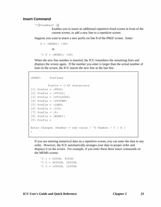
^I [<number> =];Enables you to insert an additional repetitive-fixed screen in front of thecurrent screen, or add a new line to a repetitive screen.
Suppose you want to insert a new prefix on line 8 of the PREF screen. Enter:
8 = :WORK1: <CR>
or
^I 8 = :WORK1: <CR>
When the new line number is inserted, the ICU renumbers the remaining lines anddisplays the screen again. If the number you enter is larger than the actual number oflines in the screen, the ICU inserts the new line as the last line.
(PREF) Prefixes
Prefix = 1-45 characters
[1] Prefix = :PROG:
[2] Prefix = :UTILS:
[3] Prefix = :UTILS286:
[4] Prefix = :SYSTEM:
[5] Prefix = :LANG:
[6] Prefix = :ICU:
[7] Prefix = :$:
[8] Prefix = :WORK1:
[9] Prefix =
Enter Changes [Number = new value / ^D Number / ? / H ]
:
If you are entering numerical data on a repetitive screen, you can enter the data in anyorder. However, the ICU automatically arranges your data in proper order anddisplays it on the screen. For example, if you enter these three insert commands onthe MEMS screen:
^I 1 = 2000H, 4000H
^I 2 = 80000H, 90000H
^I 3 = 10000H, 12000H
24 Chapter 2 ICU Operations
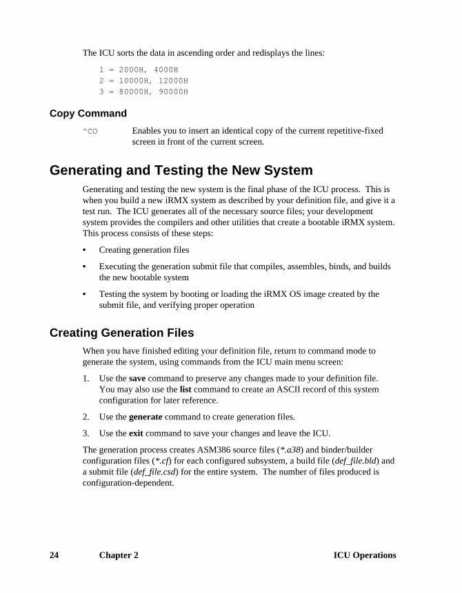
The ICU sorts the data in ascending order and redisplays the lines:
1 = 2000H, 4000H
2 = 10000H, 12000H
3 = 80000H, 90000H
Copy Command
^CO Enables you to insert an identical copy of the current repetitive-fixedscreen in front of the current screen.
Generating and Testing the New SystemGenerating and testing the new system is the final phase of the ICU process. This iswhen you build a new iRMX system as described by your definition file, and give it atest run. The ICU generates all of the necessary source files; your developmentsystem provides the compilers and other utilities that create a bootable iRMX system.This process consists of these steps:
• Creating generation files
• Executing the generation submit file that compiles, assembles, binds, and buildsthe new bootable system
• Testing the system by booting or loading the iRMX OS image created by thesubmit file, and verifying proper operation
Creating Generation FilesWhen you have finished editing your definition file, return to command mode togenerate the system, using commands from the ICU main menu screen:
1. Use the save command to preserve any changes made to your definition file.You may also use the list command to create an ASCII record of this systemconfiguration for later reference.
2. Use the generate command to create generation files.
3. Use the exit command to save your changes and leave the ICU.
The generation process creates ASM386 source files (*.a38) and binder/builderconfiguration files (*.cf) for each configured subsystem, a build file (def_file.bld) anda submit file (def_file.csd) for the entire system. The number of files produced isconfiguration-dependent.

ICU User's Guide and Quick Reference Chapter 2 25
Generating with Prefix Option
Use the prefix option with the generate command to distinguish different versions ofyour generation files from each other. When you enter the command, the ICUdisplays a prompt asking you for the prefix letter you wish to assign to the filescreated by the ICU:
ENTER a letter to be used as prefix :
Suppose you want to generate 3 different versions of the system, versions X, Y, andZ; use the letter X as your prefix option on version X, Y on version Y, and Z onversion Z. An X, Y, and Z will precede all the generation files associated with eachversion generated when you enter the generate command on the menu screen. In thiscase, the Nucleus files generated for version X will be:
XNTABL.A38XNUCDA.A38XNJOBC.A38
The files created for all other subsystems will also be preceded by the letter X.
It is also a good idea to have your input definition file start with the same prefix letteryou assign to the generated files. This enables you to determine which definition filegoes with each set of prefixed output files, and which generation submit file producesthat system. If you create a set of files with a prefix that already exists, the ICUoverwrites the previous versions.
If you do not want to use the prefix option, enter a <CR> when you are prompted forthe prefix. This causes the ICU to generate the output files without a prefix.

26 Chapter 2 ICU Operations
Executing the Generation Submit FileAmong the generation files is a submit file with the same filename as your definition
file, but with a .csd extension. For example, if the definition file used is called48612s.def, the submit file is 48612s.csd. After you leave the ICU, execute thesubmit file using the submit command and wait for your system to be generated.
See also: submit command, Command Reference
The generation submit file does this:
• Compiles source modules for each subsystem
• Binds object files together with any libraries needed by each subsystem
• Binds the subsystems and builds a bootable system
While the submit file executes, there should be no errors. If there are, they indicateserious problems that will prevent the successful generation of your system, eventhough the submit file keeps executing. Errors and warnings appear in the log filecreated by the submit command. Your compiler documentation containsexplanations of error conditions.
See also: System generation error and warning messages, in Appendix A
To successfully execute statements within the generation submit file, you must have adevelopment environment that has the appropriate compilers and utilities installed.
See also: Development environment, Appendix B
Testing the SystemThe normal development cycle is to load your system, test it, correct any errors, andreassemble or recompile any faulty program code. Then, run the ICU to regenerateyour system, and load the system again. Continue until you have created a functionaltarget system.
You can load and debug in several ways. You may use the bootstrap loader orloadrmx to load the new system from secondary storage, use a debugger program, oruse an in-circuit emulator.

ICU User's Guide and Quick Reference Chapter 2 27
Once you have created your final system, you can fine-tune the system throughrepeated generation cycles. For example, you can minimize the memory locationsallocated for the system by editing the MEMS and MEMF screens. You can alsocopy your final system to PROM.
See also: Programming Techniques and AEDIT Text Editor, for more informationon developing iRMX OS applications, and placing the OS into PROM
Restoring a Definition FileIf you create a backup file using the backup command from the main menu, therestore process can create a definition file from that backup file. To start the restoreprocess, invoke the ICU with the backup file as the input file, specifying an outputfile that is a new or an existing definition file that you want to restore to. Here is anexample invocation line:
ICU386 48612S.BCK to 48612S.DEF
The ICU signs on and responds with this:
Do you want to restore from the file? [y]/n
If you respond No, the ICU stops executing. Yes continues the restore process. Ifthe output filename already exists, the ICU displays this message:
File <output_file> exists. OVERWRITE? [y]/n:
In this example you specified an output file. If you did not specify an outputfilename on invocation you are also prompted:
Do you want to OVERWRITE the input file <in_file> ? [y/n]
If you enter No, the ICU prompts:
Enter new output filename:
You may want to use the .def suffix for the output file. Once the restore process isrunning, the ICU displays a series of * (asterisks) on the screen. If the processreaches completion with no problems, the ICU displays the main menu and youproceed as usual.

28 Chapter 2 ICU Operations
However, if an error is encountered, the ICU displays this message:
*** ERROR while restoring
The Definition File has been restored to the file: <fname.BCK>
To see the RESTORE messages, inspect the Log File: <fname.LOG>
*** NOTICE: The Definition File may have been modified while
restoring.
You may either continue to the ICU Main Menu, or
you may exit the ICU to inspect the Log File.
Continue to the ICU Main Menu? [y/n]
Log FileThe restore log file lists each screen name followed by any errors or warnings thatoccurred while restoring that screen. It also lists abbreviations of fields that were notrestored. The log file has the same name as the output file but with a .log extension.The log file enables you to compare the backup definition file and the restored file tosee which values were not restored. Run the ICU again to correct the fields in error.After that, proceed as usual.
Suppose that while restoring from file up0.bck, the ICU could not restore the CFparameter on the HARD screen. The log file entry would look like this:
ICU386 <version> Restoring from file : up0.bck <date> <time>
---- Screen : HARD ----
*** ERROR - number expected
In field : CF
---- Screen : INT ----
This example shows only a portion of the log file. The actual file will list all thescreen names in the definition file. The values for <version>, <date>, and<time> in the heading are variables.
The error messages in the log file are the same as the ICU interactive error messages.
See also: Interactive error and warning messages, in Appendix A
■■ ■■ ■■

ICU User's Guide and Quick Reference Chapter 3 29
Example ICU Session 3This chapter is a tutorial ICU session. In it, you will learn some useful screen editingtechniques while you follow these steps in the ICU process:
1. Get started
2. Enter screen-editing mode
3. Edit the definition file
4. Save and list the edited definition file
5. Generate the system
This ICU session uses a Multibus (MB) I system as the hardware platform, with anSBC 486/12S CPU board and an SBC 221 disk controller board. You will configurethe system to boot from the 221 controller rather than the 486/12S onboard SCSIcontroller. The offboard disk controller uses the MSC device driver; the SCSIcontroller uses the Intel Peripheral Controller Interface driver.
Sample command lines that you enter are shown in this type. You may enter allcommands in upper or lower case.
See also: Screen display/editing commands, in this manual

30 Chapter 3 Example ICU Session
Step 1: Getting StartedInvoke the ICU, creating a new definition file from an existing one, with thiscommand line:
icu386 48612s.bck to newsys.def
The main menu screen appears:
For general help in any screen enter H <CR>.
The following commands are available
Change
Generate
List
Save
Quit
Exit
Replace
Detail-Level
Backup
ENTER COMMAND :
You are now in command mode. You can enter any one of the commands listed onthe screen. Typically, you spend very little time in command mode while using theICU; most of the time you work in screen-editing mode.

ICU User's Guide and Quick Reference Chapter 3 31
Step 2: Entering Screen-editing ModeEnter screen-editing mode with the change command:
c <CR>
You are now editing the definition file newsys.def. This definition file is a workingcopy of 48612s.bck. The first screen appears:
(HARD) Hardware
(PC) PC Arcitecture [Yes/No]
(PCI) PCI bus extensions [Yes/No]
(TP) 8254 Timer Port [0-0FFFFH]
(CIL) Clock Interrupt Level [0-7]
(CN) Timer Counter Number [0,1,2]
(CIN) Clock Interval [0-65535 msec]
(KTR) Kernel Tick Ratio [1-65535]
(CF) Clock Frequency [0-65535 khz]
(TPS) Timer Port Separtion [0-0FFH]
(EMU) Emulate Numeric Processor [Yes/No]
(OPT) Include 386 CPU Optimizations [Yes/No]
(IF) Initialize On-board Functions [0=No / 1-0FFH]]
(BIP) Board Initialization Procedure [1-45 Chars]
Enter [Abbreviation = new value / Abbreviation ? / H]
:
This is the HARD screen, one of many that are part of this definition file. The screencontains a number of parameter lines followed by a prompt line. Each parameter lineincludes a parameter abbreviation and a range of legal values that you may enter.The prompt line appears at the bottom of the screen, ready for you to enter a newvalue for a specific parameter:
Enter [Abbreviation = new value / Abbreviation ? / H]
This is what you enter at the prompt line to change the CIL (Clock Interrupt Level)parameter from 0 to 1:
cil=1

32 Chapter 3 Example ICU Session
How To Access ICU Help ScreensWhile in screen-editing mode, you can access online help information for the wholescreen or each parameter in it. If you enter ? only, a help message appears for thecurrent screen. If you enter the parameter abbreviation followed by ?, helpinformation about that parameter appears.
For example, if you enter the abbreviation for the CIL parameter with a questionmark:
cil? <CR>
The ICU displays this:
*************************************************************
You must specify the interrupt line on the master PIC to which
the timer is connected. Note that this is not an encoded
interrupt level. The default value for this parameter is set
at 0.

ICU User's Guide and Quick Reference Chapter 3 33
Step 3: Editing the Definition FilePressing <CR> repeatedly pages through all screens in a definition file. The screensappear in order from hardware, to OS layers and associated jobs, to drivers. To moveto another screen, use the find command and supply the abbreviation. To see all thescreen abbreviations, use the find command incorrectly (with no argument) asfollows:
f <CR>
(HARD) Hardware (MBII) MBII Hardware (INT) Interrupts
(SLAVE) Slave Interrupt (SUB) Sub-systems (MEMS) Memory for System
(MEMF) Memory for FSM (PIMM) Identity Mapped (OSEXT) OS Extensions
(HI) Human Interface (HIJOB) HI Jobs (RES) Res./Recovery User
(PREF) Prefixes (HILOG) HI Logical (APPL) Application Loader
(EIOS) EIOS (ABDR) Auto Boot Dev (LOGN) Logical Names
(IOUS) I/O Users (IOJOB) I/O Jobs (BIOS) BIOS
(BIOFD) BIOS File Drvrs (PHYFD) Phys File Drvr (STRFD) Stream File Drvr
(DOSFD) DOS File Drvr (NAMFD) Named File Drvr (EDSFD) EDOS File Drvr
(CDRFD) CDROM File Drvr
(IDEVS) RadiSys Devices (PCDEV) PC Bus Devices (USERD) User Devices
(UDDM) UDS Driver Mods (SDB) System Debugger (SDM) Sys. Monitor
(NUC) Nucleus (NCOM) Comm. Service (DISPJ) DOS Dispatcher
(DRINT) DOS Resrvd Ints (SYSJ) System Jobs (PCIJ) PCI Job
(PCISC) PCI Server (DLJ) Downloader Job (ATCJ) ATCS/279/ARC Srv
(ATC50) ATCS/450 Server (BSJ) BootServer Job (FPIJ) FPI Server Job
(SSKJ) SoftScope Kernel(USERJ) User Jobs (USERM) User Modules
(TPUJ) 3rd Party UserJ (ROM) ROM Code (NET) Network Subsys
(ICMPJ) iNA960 COMMputer(NS) Name Server Cfg (NSDOM) NS Srch. Domains
(IMIPJ) iNA960 MIP Dvr (MIP1) MBI MIP Cfg.
ENTER screen abbreviation or <CR> for next list:

34 Chapter 3 Example ICU Session
Press <CR> to see the rest of the screen abbreviations including abbreviations fordevice driver screens:
<CR>
(MIP2) MBII MIP Cfg. (CEBI) CE Board Inst. (CEBN) CE Board Names
(MIPAT) PC Bus MIP Cfg. (LYR) iRMX-NET Layers (RCJ) iRMXNET Client
(FC) File Consumer (REM) Remote file Acc (RSJ) iRMXNET Server
(FS) File Server (AFA) Apex File Acc (AFAU) Afa User
(PDEV) Public Devices (PDIR) Public Dir. (UDF) User Def. File
(CDF) Client Def. (TCPJ) TCP/IP Job (IFSP) Network xfaces
(ROUTE) IP Router Info. (TCPx) TCP/IP Params x (STRM) TCP/IP Str Info
(X25SJ) X.25 Server Job (X25CJ) X.25 Client Job (INCL) Includes & Libs
(CLIB) Shared C Libry. (GEN) Gen. File Name (COMNT) Comments screen
-------------------------- DEVICE DRIVER SCREENS --------------------------
(D8274) 8274 (D8251) 8251A (D2530) 82530 (D350) SBX350 LP
(DRAM) RAM Disk (D279) SBX279A (DPCI) PCI Driver
-- MULTIBUS I DEVICE DRIVERS:
(D534) SBC534 (D544) SBC544A (D208) SBC208
(D386) SBCn86/12 LP (D220) SBC220 (D8848) TCC (D214) Mass Storage
-- MULTIBUS II DEVICE DRIVERS:
(D224A) SBC186/224A (D410) ATCS (DCOMM) SBC486SX25/486DX33
-- AT BUS DEVICE DRIVERS:
(DPCS) PC Serial (DPCC) PC Console (DPCP) PC Printer (DPCF) PC Floppy
(DPCW) PC Wini (DPCA) PC SCSI (ATPI) ATA/ATAPI
(DPCH) H550 Serial (DDOSW) Dos Wini (DDOSF) Dos Floppy
ENTER screen abbreviation:
These two lists contain all possible screens that a definition file may use. Yourdefinition file will not use all of the screens listed here. If you get lost inside theICU, the find command gets you back to this screen.
See also: Screens in Chapter 4 for screen displays
ICU User's Guide and Quick Reference Chapter 3 35
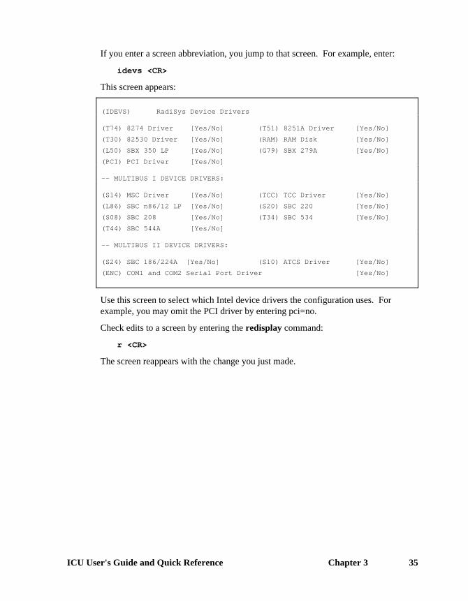
If you enter a screen abbreviation, you jump to that screen. For example, enter:
idevs <CR>
This screen appears:
(IDEVS) RadiSys Device Drivers
(T74) 8274 Driver [Yes/No] (T51) 8251A Driver [Yes/No]
(T30) 82530 Driver [Yes/No] (RAM) RAM Disk [Yes/No]
(L50) SBX 350 LP [Yes/No] (G79) SBX 279A [Yes/No]
(PCI) PCI Driver [Yes/No]
-- MULTIBUS I DEVICE DRIVERS:
(S14) MSC Driver [Yes/No] (TCC) TCC Driver [Yes/No]
(L86) SBC n86/12 LP [Yes/No] (S20) SBC 220 [Yes/No]
(S08) SBC 208 [Yes/No] (T34) SBC 534 [Yes/No]
(T44) SBC 544A [Yes/No]
-- MULTIBUS II DEVICE DRIVERS:
(S24) SBC 186/224A [Yes/No] (S10) ATCS Driver [Yes/No]
(ENC) COM1 and COM2 Serial Port Driver [Yes/No]
Use this screen to select which Intel device drivers the configuration uses. Forexample, you may omit the PCI driver by entering pci=no.
Check edits to a screen by entering the redisplay command:
r <CR>
The screen reappears with the change you just made.

36 Chapter 3 Example ICU Session
Exploring Device Driver ScreensTo look at a specific hard disk device driver and its parameters, display the help listsfor screen abbreviations by entering the find command with no arguments (f<CR>). If you press <CR> instead of entering a screen abbreviation, the second oftwo lists appears:
(MIP2) MBII MIP Cfg. (CEBI) CE Board Inst. (CEBN) CE Board Names
(MIPAT) PC Bus MIP Cfg. (LYR) iRMX-NET Layers (RCJ) iRMXNET Client
(FC) File Consumer (REM) Remote file Acc (RSJ) iRMXNET Server
(FS) File Server (AFA) Apex File Acc (AFAU) Afa User
(PDEV) Public Devices (PDIR) Public Dir. (UDF) User Def. File
(CDF) Client Def. (TCPJ) TCP/IP Job (IFSP) Network xfaces
(ROUTE) IP Router Info. (TCPx) TCP/IP Params x (STRM) TCP/IP Str Info
(X25SJ) X.25 Server Job (X25CJ) X.25 Client Job (INCL) Includes & Libs
(CLIB) Shared C Libry. (GEN) Gen. File Name (COMNT) Comments screen
-------------------------- DEVICE DRIVER SCREENS --------------------------
(D8274) 8274 (D8251) 8251A (D2530) 82530 (D350) iSBX350 LP
(DRAM) RAM Disk (D279) iSBX279A (DPCI) PCI Driver
-- MULTIBUS I DEVICE DRIVERS:
(D534) SBC534 (D544) SBC544A (D208) SBC208
(D386) SBCn86/12 LP (D220) SBC220 (D8848) TCC (D214) Mass Storage
-- MULTIBUS II DEVICE DRIVERS:
(D224A) SBC186/224A (D410) ATCS (DCOMM) SBC486SX25/486DX33
-- AT BUS DEVICE DRIVERS:
(DPCS) PC Serial (DPCC) PC Console (DPCP) PC Printer (DPCF) PC Floppy
(DPCW) PC Wini (DPCA) PC SCSI (ATPI) ATA/ATAPI
(DPCH) H550 Serial (DDOSW) Dos Wini (DDOSF) Dos Floppy
ENTER screen abbreviation:

ICU User's Guide and Quick Reference Chapter 3 37
Abbreviations for device driver screens appear at the bottom of the list. Each ofthese driver screens represents a DINFO (Device Information) table entry forsupported Intel device drivers. For example, enter the MSC device driver screenabbreviation:
d214 <CR>
You see this DINFO screen:
(D214) Mass Storage Controller Driver
(DEV) Device Name [1-16 Chars]
(IL) Interrupt Level [Encoded Level]H
(ITP) Interrupt Task Priority [0-255]
(WIP) Wakeup I/O Port [0-0FFFFH]
(IPA) I/O Processor Block Address [0-0FFFFFH]
(SB) Size of Buffer [082C4H-0FFFFFH]
Press <CR> and you are asked:
Do you want any/more Mass Storage Controller DEVICEs ?
Press <CR> again to see the first of many UINFO (Unit Information) screens alreadycreated for this device. The ICU can provide a screen for every UINFO table andDUIB (Device-unit Information Block) associated with a particular DINFO screen.
See also: Chapter 4 for composites of device driver screens;Online help descriptions of screen parameters;Driver Programming Concepts, for definitions of DINFO, UINFO, andDUIB data structures
If you enter Yes, the ICU creates a fresh UINFO screen for you and inserts it in frontof the default UINFO screens, ready for you to enter values for parameters.

38 Chapter 3 Example ICU Session
However, you should edit existing UINFO and DUIB screens whenever possible,especially if you are using an Intel device driver. The OS-supplied UINFO andDUIB screens may already provide support for your device, requiring only that youedit specific parameters. Here is the first UINFO screen for the MSC device driver:
(U214) Mass Storage Controller Unit Information
(DEV) Device Name [1-16 Chars]
(NAM) Unit Info Name [1-16 Chars]
(MR) Maximum Retries [0-0FFFFH]
(CS) Cylinder Size [0-0FFFFH]
(NC) Number of Cylinders [0-0FFFFH]
(NFH) Number of Heads/Fixed Disk [0-0FFH]
(NRH) Number of Heads/Removable Disk [0-0FFH]
(NS) Number of Sectors/Track [0-0FFFFH]
(NAC) Number of Alternate Cylinders [0-0FFH]
(SSN) Starting Sector Number [0-0FFFFFFFFH]
(BTI) Bad Track Information [Yes/No]
(HLT) Head Load Time [0-0FFH]
(SR) Step Rate [0-0FFH]
You can get from the UINFO screens to the DUIB screens in two ways: page throughall of the UINFO screens by pressing <CR> repeatedly, or use the next command,which is quicker. Enter:
n <CR>

ICU User's Guide and Quick Reference Chapter 3 39
You are shown the first of many DUIB screens:
(I214) Mass Storage Controller Device-Unit Information
(DEV) Device Name [1-16 Chars]
(NAM) Device-Unit Name [1-14 Chars]
(PFD) Physical File Driver Required [Yes/No]
(NFD) Named File Driver Required [Yes/No]
(DOS) DOS File Driver Required [Yes/No]
(SDD) Single or Double Density Disks [Single/Double]
(SDS) Single or Double Sided Disks [Single/Double]
(EFI) Quad or Double Density Disks [8/5]
(SUF) Standard or Uniform Format [Standard/Uniform]
(GRA) Granularity [0-0FFFFH]
(DSZ) Device Size [0-0FFFFFFFFH]
(UN) Unit Number on this Device [0-0FFH]
(UIN) Unit Info Name [1-16 Chars]
(RUT) Request Update Timeout [0-0FFFFH]
(NB) Number of Buffers [0 or 1-0FFFFH]
(CUP) Common Update [Yes/No]
(MB) Max Buffers [0-0FFH]
Setting Automatic Boot Device RecognitionTo configure an MSC device, such as an SBC 221 controller, to boot the system, usethe find command and supply the abbreviation for the Automatic Boot DeviceRecognition screen as the argument. (If you don’t know the screen abbreviation,enter the find command with no arguments to get help on screen abbreviations.)
f abdr <CR>
(ABDR) Automatic Boot Device Recognition
(DLN) Default System Device Logical Name [1-12 Chars]
(DPN) Default System Device Physical Name [1-12 Chars]
(DFD) Default Sys Dev File Driver [P/S/N/R/E/D]
(DO) Default System Device Owner's ID [0-0FFFFH]
Change the name of the physical device that the system will boot from to (DPN).Then use the redisplay command to verify the change you just made:
r <CR>
When you are finished, leave screen-editing mode by using the cancel command:
c <CR>

40 Chapter 3 Example ICU Session
Step 4: Saving and Listing the Edited Definition FileNow that you are back in command mode (indicated by the presence of the mainmenu screen), use the save command to store your screen edits to the definition filespecified when you invoked the ICU:
s <CR>
When the save operation is complete, the ICU responds with this message:
The definition file has been written to file: NEWSYS.BCK
For future reference, list all of the parameters contained in the definition file to anASCII file with the list command:
l newsys.lst <CR>
When the listing operation is complete, the ICU responds with this message:
The definition file has been listed to file: NEWSYS.LST

ICU User's Guide and Quick Reference Chapter 3 41
Step 5: Generating the SystemCreate all of the files to build the new system with the generate command:
g <CR>
You are prompted to:
ENTER a letter to be used as prefix :
Press <CR> for this example, to proceed with system generation.
See also: Generating with prefix option, in this manual
During generation, the ICU indicates the beginning and ending of each subsystemgeneration, and the completion of the generation process:
Beginning NUCLEUS File Generation
...................................................DONE
Beginning BIOS File Generation
...................................................DONE
Beginning EIOS File Generation
...................................................DONE
Beginning LOADER File Generation
...................................................DONE
Beginning HI File Generation
...................................................DONE
Beginning UDI File Generation
...................................................DONE
Beginning SDM III File Generation
...................................................DONE
Beginning SDB File Generation
...................................................DONE
Beginning CONTROL Files Generation
...................................................DONE
Beginning ESUBMIT File Generation
...................................................DONE
Beginning BUILD File Generation
...................................................DONE
To create your application system, type:
SUBMIT NEWSYS.CSD <CR>

42 Chapter 3 Example ICU Session
Use the quit command to leave the ICU:
q <CR>
Then execute the generation submit file and the new system is created for you.
■■ ■■ ■■

ICU User's Guide and Quick Reference Chapter 4 43
ICU Quick Reference
4Screen Names and Acronyms
Since the actual default values seen on the screens depend onthe system bus type and definition file, this manual does notshow default values on the sample screens. In general, use thedefaults in the definition files unless you have a specific needto change them.
✏ NoteThis manual does not list all possible ICUscreens, and it contains only a brief summaryfor each parameter. For more specificdetails, see the ICU help messages for eachscreen and parameter.

Chapter 4 ICU Quick Reference44
Acronym Screen Name Page
(ABDR) Automatic Boot Device Recognition ............................. 56(AFA) Apex File Access.......................................................... 86(AFAU) AFA User...................................................................... 87(APPL) Application Loader ....................................................... 47(ATC50) MBII ATCS/450 Server Job .......................................... 113(ATCJ) MBII ATCS/279/ARC Server Job.................................. 112(BIOFD) BIOS File Drivers.......................................................... 60(BIOS) BIOS............................................................................. 47(BSJ) MSA BootServer Job.................................................... 114(CDF) Client Definition File ..................................................... 91(CEBI) COMMengine Board Instance Load Method for MBII... 78(CEBN) COMMengine Board Names ........................................ 78(CLIB) Shared C Library .......................................................... 103(COMNT) Comments for Build File ............................................... 49(DISPJ) DOS Extender Dispatcher Job ..................................... 54(DLJ) MBII Downloader Job ................................................... 112(DOSFD) DOS File Driver ............................................................ 60(DRINT) DOS Extender Reserved Interrupts.............................. 55(EDSFD) EDOS File Driver.......................................................... 60(EIOS) EIOS............................................................................. 56(FC) File Consumer Configuration........................................ 82(FPIJ) FPI Server Job ............................................................. 115(FS) File Server Configuration ............................................. 85(continued next page)

ICU User's Guide and Quick Reference Chapter 4 45
Acronym Screen Name Page
(GEN) Generate File Names .................................................. 61(HARD) Hardware..................................................................... 62(HI) Human Interface.......................................................... 64(HIJOB) HI Jobs ........................................................................ 65(HILOG) HI Logical Names ........................................................ 67(ICMPJ) iNA 960 COMMputer Job ............................................ 80(IDEVS) RadiSys Device Drivers............................................... 50(IMIPJ) iNA MIP Driver Job ...................................................... 74(INCL) Includes and Libraries ................................................. 68(INT) Interrupts ..................................................................... 70(IOJOB) I/O Jobs ....................................................................... 58(IOUS) I/O Users ..................................................................... 58(LOGN) Logical Names............................................................. 57(MBII) Multibus II Hardware ................................................... 98(MEMF) Memory for Free Space Manager................................ 72(MEMS) Memory for System ..................................................... 72(MIP1) MIP Configuration for MBI ........................................... 75(MIP2) MIP Configuration for MBII .......................................... 77(MIPAT) MIP Configuration for PC Bus ..................................... 79(NAMFD) Named File Driver ....................................................... 60(NCOM) Nucleus Communication Service................................. 96(NET) Network Subsystem..................................................... 73(NS) Name Server Configuration......................................... 92(NSDOM) Name Server Search Domains.................................... 93(NUC) Nucleus ....................................................................... 94(OSEXT) O.S. Extension ............................................................ 101(PCDEV) PC Bus Device Drivers ................................................ 50(PCIJ) PCI Server Job ............................................................ 110(PCISC) PCI Server Controller Configuration............................ 111(PDEV) Public Devices............................................................. 88(PDIR) Public Directory ........................................................... 89(PHYFD) Physical File Driver...................................................... 60(PIMM) Paging Identity Mapped Memory................................. 72(PREF) Prefixes ....................................................................... 67(QUERY) Query screen............................................................... 101(RCJ) iRMX-Net Client........................................................... 81(REM) Remote File Access..................................................... 83(RES) Resident/Recovery User.............................................. 66(ROM) ROM Code .................................................................. 102(RSJ) iRMX-NET Server........................................................ 84(SDB) System Debugger........................................................ 107(SDM) System Debug Console............................................... 107(SLAVE) Slave Interrupt Levels.................................................. 70(continued next page)

Chapter 4 ICU Quick Reference46
Acronym Screen Name Page
(SSKJ) SoftScope Kernel Job................................................... 116(STRFD) Stream File Driver ........................................................ 60(SUB) Sub-systems................................................................. 105(SYSJ) System Jobs................................................................. 109(TPUJ) Third Party Tools Generated User Job......................... 116(UDDM) UDS Device Driver Modules......................................... 54(UDF) User Definition File....................................................... 90(USERD) User Devices ................................................................ 53(USERJ) User Jobs ..................................................................... 117(USERM) User Modules ............................................................... 118

ICU User's Guide and Quick Reference Chapter 4 47
Application Loader Screen(APPL) Application Loader
(ASC) All System Calls [Yes/No=only RQ$A$LOAD]
(DMP) Default Memory Pool Size [0-0FFFFFFFH]
(RBS) Read Buffer Size [0-0FFFFH]
(VSG) Virtual Segment Size [0-0FFFFFFFFH]
(ASC) Yes Includes all the AL system calls and requires the EIOS.No Includes only the rq_a_load system call and does not require the EIOS.
(DMP) Specifies in 16-byte paragraphs the minimum memory pool size allocated to I/O jobscreated by the AL.
(RBS) Specifies in bytes the buffer size the AL uses when loading data from secondarystorage.
(VSG) Specifies in bytes the virtual segment size created for each flat model program thatthe AL loads.
BIOS Screen(BIOS) BIOS
(ADP) Attach Device Task Priority [1-255]
(TF) Timing Facilities Required [Yes/No]
(TTP) Timer Task Priority [0-255]
(CON) Connection Job Delete Priority [0-255]
(ACE) Ability to Create Existing Files [Yes/No]
(SMI) System Manager ID [Yes/No]
(CUT) Common Update Timeout [0-65535]
(TSC) Terminal Support Code [Yes/No]
(CST) Control-Sequence Translation [Yes/No]
(OSC) Terminal OSC Controls [Yes/No]
(TSP) Tape Support [Yes/No]
(PMI) BIOS Pool Minimum [0-0FFFFFFFH]
(PMA) BIOS Pool Maximum [0-0FFFFFFFH]
(LDV) Number of loadable Devices [0-0FFFFH]
(LDU) Number of loadable Device Units [0-0FFFFH]
(GC) Global Clock [ATRT/546/CSM/None]
(GCN) Global Clock Name [1-13 Chars]
(SES) Suppress E$SPACE on overflow [Yes/No]

Chapter 4 ICU Quick Reference48
(ADP) Specifies in decimal the priority of the attach device task.
(TF) Specifies whether the I/O system includes timing facilities. See also CUT.
(TTP) Specifies in decimal the timer task priority if you included timing facilities.
(CON) Specifies in decimal the priority of the BIOS task that deletes file and deviceconnections.
(ACE) Specifies whether the OS returns an error if you attempt duplicate file creation.
(SMI) Specifies whether user ID 0 has system manager attributes.
(CUT) Specifies in decimal units representing 10 millisecond Nucleus clock ticks how longthe BIOS waits before updating all designated devices with any data buffered inmemory, regardless of the activity on an individual device-unit.
(TSC) Specifies whether to include the TSC; required by the HI and any terminal driver.
(CST) Specifies if the translation capabilities are supported by the TSC.
(OSC) Specifies whether to include OSC controls for terminals.
(TSP) Specifies tape support. Use the default.
(PMI),(PMA)Specifies in 16-byte paragraphs the minimum and maximum sizes of the BIOSmemory pool.
(LDV) Specifies in decimal how many loadable devices you want.
(LDU) Specifies in decimal how many loadable device units you want. LDU must exceedLDV.
(GC) Specifies whether there is an on-board, hardware time-of-day clock that maintains thecurrent date and time for the entire system, even when it is turned off.
(GCN) Specifies the global clock name.
(SES) Determines whether the E_SPACE condition code displays. If you select Yes, thenthe condition code does not display, but returned data may contain truncated values.
The E_SPACE condition code displays when either rq_a_get_file_status orrq_a_get_connection_status is called for a file that overflows any field in thefile_status or connection_status structure. This can occur on a 48- or 64-bit Namedfile system. The new extended calls, req_a_get_file_status orrqe_a_get_connection_status, avoid this problem, but legacy code may exhibit thisbehavior.
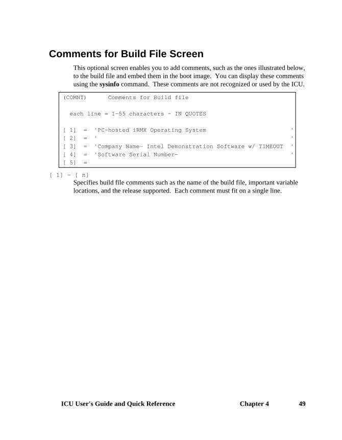
ICU User's Guide and Quick Reference Chapter 4 49
Comments for Build File ScreenThis optional screen enables you to add comments, such as the ones illustrated below,to the build file and embed them in the boot image. You can display these commentsusing the sysinfo command. These comments are not recognized or used by the ICU.
(COMNT) Comments for Build file
each line = 1-55 characters - IN QUOTES
[ 1] = 'PC-hosted iRMX Operating System '
[ 2] = ' '
[ 3] = 'Company Name- Intel Demonstration Software w/ TIMEOUT '
[ 4] = 'Software Serial Number- '
[ 5] =
[ 1] - [ n]Specifies build file comments such as the name of the build file, important variablelocations, and the release supported. Each comment must fit on a single line.

Chapter 4 ICU Quick Reference50
Device Driver Screens
RadiSys Device Drivers ScreenThis screen displays the RadiSys-supplied drivers for Multibus systems.
(IDEVS) RadiSys Device Drivers
(T74) 8274 Driver [Yes/No] (T51) 8251A Driver [Yes/No]
(T30) 82530 Driver [Yes/No] (RAM) RAM Disk [Yes/No]
(L50) SBX 350 LP [Yes/No] (PCI) PCI Driver [Yes/No]
(G79) SBX 279A [Yes/No]
-- MULTIBUS I DEVICE DRIVERS:
(S14) MSC Driver [Yes/No] (TCC) TCC Driver [Yes/No]
(L86) SBC n86/12 LP [Yes/No] (S20) SBC 220 [Yes/No]
(S08) SBC 208 [Yes/No] (T34) SBC 534 [Yes/No]
(T44) SBC 544A [Yes/No]
-- MULTIBUS II DEVICE DRIVERS:
(S24) SBC 186/224A [Yes/No] (S10) ATCS Driver [Yes/No]
(ENC) COM1 and COM2 Serial Port Driver [Yes/No]
PC Bus Device Drivers ScreenThis screen displays the Intel-supplied drivers for PCs.
(PCDEV) PC Bus Device Drivers
(PCS) PC Bus Serial [Yes/No] (PCC) PC Bus Console [Yes/No]
(PCP) PC Bus Printer [Yes/No] (PCF) PC Bus Floppy [Yes/No]
(ATP) ATA/ATAPI [Yes/No] (PCH) H 550 Serial [Yes/No]
(PCW) PC Bus Wini [Yes/No] (PCA) PC Bus SCSI [Yes/No]
(DHD) Dos Wini [Yes/No] (DFD) Dos Floppy [Yes/No]
For each driver you specify, two or three additional screens appear: the Driverscreen, the Unit Information screen, and/or the Device-Unit Information screen.
The ICU stores all the device driver screens by type, not by device. This means thatall Device Driver screens, all Unit Information screens and all Device-UnitInformation screens are stored together. The ICU associates Unit Information andDevice-Unit Information screens to a particular device driver by the device name youenter in the DEV parameter on the particular Device Driver screen.

ICU User's Guide and Quick Reference Chapter 4 51
Parameters on the screens vary, depending on the device type. Only the commonparameters are illustrated on the composite screens. For information on individualdriver screens and driver options, use the ICU help screens.
Driver Screen CompositeA screen like this appears for every driver you specify on the IDEVS or PCDEVscreen.
(xxx) xxx Driver
(DEV) Device Name [1-16 Chars]
(IL) Interrupt Level [Encoded Level]
(ITP) Interrupt Task Priority [0-255]
(DEV) Specifies a name for a particular device and associates that device with all the unitsand DUIBs that belong to it. This parameter appears on every device driver screen.
(IL) Specifies the encoded interrupt level for the driver. The interrupt task uses this valueto associate the interrupt task with the correct interrupt level. This parameter appearson most device driver screens.
(ITP) Specifies in decimal the initial priority of the device's interrupt task. The actualpriority of the interrupt task changes because the Nucleus adjusts an interrupt task'spriority according to the interrupt level that it services. This parameter appears onmany device driver screens.
Unit Information Screen CompositeThis screen appears for most device drivers. The ICU uses this information to createa unit information table for the driver.
(xxx) xxx Driver Unit Information
(DEV) Device Name [1-16 Chars]
(NAM) Unit Info Name [1-16 Chars]
(DEV) Specifies the logical ICU connection between a driver and all of its units. Enter thename you entered in the DEV parameter on the Driver screen. This parameterappears on every Unit Information screen.
(NAM) Specifies a unique name for this unit information table. This parameter appears onevery Unit Information screen.

Chapter 4 ICU Quick Reference52
Device-Unit Information Screen CompositeThis screen appears for most device drivers. The ICU uses this information to createa DUIB for the driver.
(xxx) xxx Driver Device-Unit Information
(DEV) Device Name [1-16 Chars]
(NAM) Device-Unit Name [1-14 Chars]
(UN) Unit Number on this Device [0-0FFH]
(UIN) Unit Info Name [1-16 Chars]
(DEV) Specifies the logical ICU connection between a driver and all of its DUIBs, enablingyou to delete all the related units and DUIBs at the same time. Enter the name youentered in the DEV parameter on the Driver screen. This parameter appears on everyDevice-Unit screen.
(NAM) Specifies a name that uniquely identifies the device-unit for the I/O System. Use thisphysical name when you invoke the attachdevice command, thea_physical_attach_device system call, or the logical_attach_device system call.This parameter appears on every Device-Unit screen.
(UN) Specifies the unit number of this device-unit, beginning with 0. This parameterappears on many Device-Unit screens.
(UIN) Specifies the name of the unit information table for this DUIB. This parameterappears on many Device-Unit screens.
See also: Driver Programming Concepts, particularly the DUIB and UDSchapters, for more information on configuring device drivers

ICU User's Guide and Quick Reference Chapter 4 53
User Devices ScreenThis screen enables you to add your own devices to the system. It appears if youanswer Yes to the Query screen.
(USERD) User Devices
(OPN) Random Access Object Code Path Name [1-45 Chars/NONE]
(TOP) Terminal Object Code Path Name [1-45 Chars/NONE]
(DPN) Duib Source Code Path Name [1-45 Chars/NONE]
(DUP) Random Access Device and Unit Source Code Path Name [1-45 Chars/NONE]
(TUP) Terminal Device and Unit Source Code Path Name [1-45 Chars/NONE]
(ND) Number of User Defined Devices [0-0FFH]
(NDU) Number of User Defined Device-Units [0-0FFH]
Terminal Device and Unit Information Names [1-16 Chars]
(N01) (N02) (N03)
(N04) (N05) (N06)
(N07) (N08) (N09)
(N10) (N11) (N12)
(N13) (N14) (N15)
(N16) (N17) (N18)
(OPN) Specifies the object code pathname for your custom random access device drivers.
(TOP) Specifies the object code pathname for your custom terminal device drivers.
(DPN) Specifies the include file pathname for your custom DUIBS.
(DUP) Specifies the include file pathname for your device or unit information tables forcustom random access device drivers.
(TUP) Specifies the include file pathname for your device or unit information tables forcustom Terminal device drivers.
(ND) Specifies how many different device numbers you used in the DUIBs in the DUIBinclude file.
(NDU) Specifies how many different device-unit numbers you used in the DUIBs in theDUIB include file.
Terminal Device and Unit Information NamesSpecifies the terminal device-unit name.

Chapter 4 ICU Quick Reference54
UDS Device Driver Modules ScreenThis screen enables you to specify object code pathnames for your custom devices.
(UDDM) UDS Device Driver Modules
Module= Driver type , Object code pathname
[T/C] , [1-55 Chars]
[ 1] Module=
Driver typeSpecifies whether the device is a Terminal or Common/Named.
Object code pathnameSpecifies the object code pathname for this device.
DOS Extender Dispatcher Screens(DISPJ) DOS Extender Dispatcher Job
(ODS) Object Directory Size [0-3840]
(PMI) Pool Minimum [60H-0FFFFFFFH]
(PMA) Pool Maximum [60H-0FFFFFFFH]
(MOB) Maximum Objects [1-0FFFFH]
(MTK) Maximum Tasks [1-0FFFFH]
(MPR) Maximum Priority [0-255]
(PV) Parameter Validation [Yes/No]
(TP) Task Priority [0-255]
(SSI) Stack Size [0-0FFFFH]
(VIE) Enable interrupt virtualization [Yes/No]
(ODS) Specifies in decimal how many entries can be in this job's object directory. 0 meanscreate no directory.
(PMI),(PMA)Specifies in 16-byte paragraphs the minimum and maximum sizes of this job'smemory pool.
(MOB) Specifies how many objects can exist simultaneously in this job.
(MTK) Specifies how many tasks can exist simultaneously in this job.
(MPR) Specifies in decimal the highest priority of tasks in this job.

ICU User's Guide and Quick Reference Chapter 4 55
(PV) Specifies whether to include parameter validation for Nucleus system calls made bytasks in this job, if you included system-level parameter validation.
(TP) Specifies in decimal the priority of this job's initialization task.
(SSI) Specifies in bytes the size of the initialization task's stack segment.
(VIE) Specifies whether to enable Interrupt Virtualization.
DOS Extender Reserved Interrupts ScreenThis screen appears only if you enable VIE on the DISPJ screen.
(DRINT) DOS Extender Reserved Interrupts
(ML0) Master Level 0 [Yes/No] (SL0) Slave Level 0 [Yes/No]
(ML1) Master Level 1 [Yes/No] (SL1) Slave Level 1 [Yes/No]
(ML2) Master Level 2 [Yes/No] (SL2) Slave Level 2 [Yes/No]
(ML3) Master Level 3 [Yes/No] (SL3) Slave Level 3 [Yes/No]
(ML4) Master Level 4 [Yes/No] (SL4) Slave Level 4 [Yes/No]
(ML5) Master Level 5 [Yes/No] (SL5) Slave Level 5 [Yes/No]
(ML6) Master Level 6 [Yes/No] (SL6) Slave Level 6 [Yes/No]
(ML7) Master Level 7 [Yes/No] (SL7) Slave Level 7 [Yes/No]
(ML0) - (ML7)ML0 is the system clock; ML2 is the slave PIC. Others specify interrupt levels usedby devices.
(SL0) - (SL7)Specify interrupt levels used by devices.
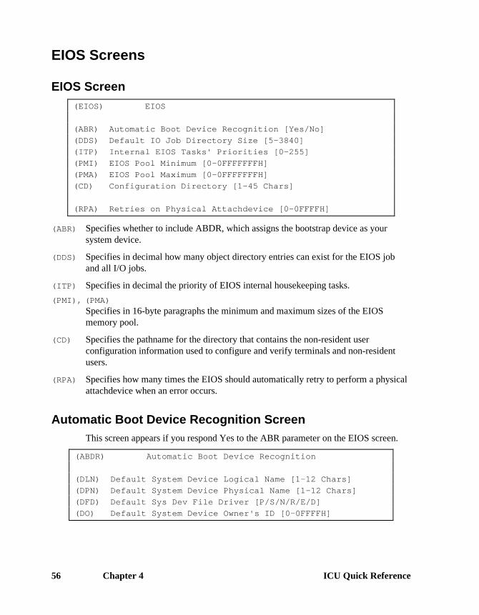
Chapter 4 ICU Quick Reference56
EIOS Screens
EIOS Screen(EIOS) EIOS
(ABR) Automatic Boot Device Recognition [Yes/No]
(DDS) Default IO Job Directory Size [5-3840]
(ITP) Internal EIOS Tasks' Priorities [0-255]
(PMI) EIOS Pool Minimum [0-0FFFFFFFH]
(PMA) EIOS Pool Maximum [0-0FFFFFFFH]
(CD) Configuration Directory [1-45 Chars]
(RPA) Retries on Physical Attachdevice [0-0FFFFH]
(ABR) Specifies whether to include ABDR, which assigns the bootstrap device as yoursystem device.
(DDS) Specifies in decimal how many object directory entries can exist for the EIOS joband all I/O jobs.
(ITP) Specifies in decimal the priority of EIOS internal housekeeping tasks.
(PMI), (PMA)Specifies in 16-byte paragraphs the minimum and maximum sizes of the EIOSmemory pool.
(CD) Specifies the pathname for the directory that contains the non-resident userconfiguration information used to configure and verify terminals and non-residentusers.
(RPA) Specifies how many times the EIOS should automatically retry to perform a physicalattachdevice when an error occurs.
Automatic Boot Device Recognition ScreenThis screen appears if you respond Yes to the ABR parameter on the EIOS screen.
(ABDR) Automatic Boot Device Recognition
(DLN) Default System Device Logical Name [1-12 Chars]
(DPN) Default System Device Physical Name [1-12 Chars]
(DFD) Default Sys Dev File Driver [P/S/N/R/E/D]
(DO) Default System Device Owner's ID [0-0FFFFH]

ICU User's Guide and Quick Reference Chapter 4 57
(DLN) Specifies the logical name of the system device.
(DPN) Specifies the physical device unit name; do not use a name you specified in theLOGN screen.
(DFD) Specifies the file driver type for the system device.
(DO) Specifies the owner ID of the system device; the default is the system manager.
Logical Names ScreenThis is a repetitive screen. Specify up to 20 logical names, including the twodefaults.
(LOGN) Logical Names
Logical Name = logical_name, device_name, file_driver, owners-id
[1-12 Chars], [1-14 Chars], [P/S/N/R/E/D], [0-0FFFFH]
[1] Logical Name = BB , BB , PHYSICAL , 0H
[2] Logical Name = STREAM , STREAM , STREAM , 0H
[3] Logical Name = , ,
[4]
Logical_nameSpecifies the logical name of the device.
device_nameSpecifies a name that uniquely identifies the device-unit for the I/O System. Use thisname when you invoke commands or system calls requiring a device name.
file_driverSpecifies the file driver type for the device.
owners-idSpecifies the owner ID of the device; this does not need to be defined on the IOUSscreen.

Chapter 4 ICU Quick Reference58
I/O Users ScreenThis is a repetitive screen. Specify up to 20 user names.
(IOUS) I/O Users
I/O User = user name , Owner-ID[,ID,ID,ID,ID]
[1-12 Chars], [0-0FFFFH]
[1] I/O User = WORLD , 0FFFFH, 0FFFFH, 0FFFFH, 0FFFFH, 0FFFFH
[2] I/O User =
user nameSpecifies the name of the user object.
Owner-IDThe first ID is the Owner ID; you can specify up to 4 additional User IDs.
I/O Jobs ScreenThis is a repetitive screen. Specify I/O jobs in the order you want them created andinitialized.
(IOJOB) I/O Jobs
(IJD) I/O Job Default Prefix [1-12 Chars]
(DU) Default User [1-12 Chars]
(PMI) Pool Minimum [20H-0FFFFFFFH]
(PMA) Pool Maximum [20H-0FFFFFFFH]
(EHS) Exception Handler Entry Point [1-31 Chars]
(EM) Exception Mode [Never/Prog/Environ/All]
(PV) Parameter Validation [Yes/No]
(TP) Task Priority [0-255]
(TSA) Task Entry Point [1-31 Chars]
(VAR) Public Variable Name [1-31 Chars]
(SSA) Stack Segment Address [SS:SP]
(SSI) Stack Size [0-0FFFFH]
(NPX) Numeric Processor Extension Used [Yes/No]

ICU User's Guide and Quick Reference Chapter 4 59
(IJD) Specifies the logical name for this I/O job.
(DU) Specifies the default user object for this I/O job.
(PMI),(PMA)Specifies in 16-byte paragraphs the minimum and maximum sizes of this I/O job'smemory pool.
(EHS) Specifies the exception handler for this I/O Job.
(EM) Specifies the exception mode of the exception handler listed in EHS.
(PV) Specifies whether the Nucleus performs parameter validation for all Nucleus systemcalls made in this I/O job.
(TP) Specifies in decimal the priority of this job's initialization task.
(TSA) Specifies the PUBLIC name of the I/O job's entry procedure.
(VAR) Specifies the PUBLIC name of any of the I/O job's public variables.
(SSA) Specifies the address of the initialization task's stack.
(SSI) Specifies in bytes the size of the initialization task's stack segment.
(NPX) Specifies whether the I/O job's initial task contains floating-point instructions.

Chapter 4 ICU Quick Reference60
File Drivers Screens
BIOS File Drivers Screen(BIOFD) BIOS File Drivers
(NFD) Named File Driver [Yes/No]
(DFD) DOS File Driver [Yes/No]
(EFD) EDOS File Driver [Yes/No]
(CFD) CDROM File Driver [Yes/No]
(MFD) Max. Number of Loadable File Drivers [0-0FFH]
(NFD), (DFD), (EFD), (CFD)Specifies which file drivers to include in the system.
(MFD) Specifies how many loadable drivers to include in the system.
File Driver Screen CompositesThe file driver screens are: Physical (PHYFD), Stream (STRFD), DOS (DOSFD),Named (NAMFD), EDOS (EDSFD), and CD ROM (CDRFD). The EDOS FileDriver screen is representative of all the file driver screens. Only the he DOS andEDOS File Driver screens have an LCN parameter. The Named and CDROM filedriver do not have a DDS nor a DRQ parameter.
(EDSFD) EDOS File Driver
(ISS) I/O Task Stack Size [0-65534]
(ITP) I/O Task Priority [0-255]
(DDS) Device Descriptor Size [0-255]
(DRQ) DUIBs Required [Yes/No]
(LCN) Force DOS Filenames to Lower Case [Yes/No]
(ISS) Specifies in bytes the size of the I/O task's stack.
(ITP) Specifies in decimal the priority of the I/O task.
(DDS) Specifies the size of the device descriptor for the file driver.
(DRQ) Specifies whether the file driver requires DUIBs.
(LCN) (DOS and EDOS file drivers only) Specifies whether to force DOS filenames tolower case.
(EBS) (Physical and Named file drivers only) Specifies the size in bytes of the EIOS bufferused to perform I/O operations.

ICU User's Guide and Quick Reference Chapter 4 61
Generate File Names Screen(GEN) Generate File Names
(RMB) Remote Boot Translation [Yes/No]
(RBF) Remote Boot File Name [1-55 Chars]
(ROF) ROM Code File Name [1-55 Chars]
(RAF) RAM Code File Name [1-55 Chars]
(RMB) Specifies whether to boot the system remotely.
(RBF) Specifies the pathname of the application system's REMOTE bootloadable file.
(ROF) Specifies the pathname of your system's ROM code.
(RAF) Specifies the pathname of the system's local bootloadable file.

Chapter 4 ICU Quick Reference62
Hardware Screens
Hardware Screen(HARD) Hardware
(PC) PC Architecture [Yes/No]
(PCI) PCI bus extensions [Yes/No]
(TP) 8254 Timer Port [0-0FFFFH]
(CIL) Clock Interrupt Level [0-7]
(CN) Timer Counter Number [0,1,2]
(CIN) Clock Interval [0-65535 msec]
(KTR) Kernel Tick Ratio [1-65535]
(CF) Clock Frequency [0-65535 khz]
(TPS) Timer Port Separtion [0-0FFH]
(EMU) Emulate Numeric Processor [Yes/No]
(OPT) Include 386 CPU Optimizations [Yes/No]
(IF) Initialize On-board Functions [0=No/1-0FFH]
(BIP) Board Initialization Procedure [1-45 Chars]
(PC) Defines the general architecture (PC or non-PC) used in the system.
(PCI) If the value of PC Architecture is Yes, this parameter determines whether to includethe PCI bus extensions in the system. If your system has a PCI bus, select Yes.
(TP) Specifies the base (lowest valued) port address of the 8254 PIT timer, which providesOS timing.
(CIL) Specifies the master PIC interrupt line (not an encoded level) that the timer isconnected to.
(CN) Specifies the PIT counter used by the Nucleus, usually 0; use the default for Intelboards.
(CIN) Specifies in milliseconds the standard Nucleus clock tick; for portability, use thedefault.
(KTR) Specifies the tick interval in iRMK system calls; the Nucleus tick interval remainsunchanged. Use the default Nucleus clock tick unless you need a smaller iRMKKernel tick interval.
(CF) Specifies in kilohertz the frequency of the clock input to the timer; use the default forRadiSys boards. RadiSys Multibus I processor boards use clock frequency 1228.8kilohertz (entered as 1229) for this parameter. RadiSys Multibus II processor boardsuse clock frequency 1250 kilohertz (entered as 1250) for this parameter.
ICU User's Guide and Quick Reference Chapter 4 63
(TPS) Specifies the 8254 PIT timer port separation; all RadiSys processor boards use avalue of 2 for this parameter.
(EMU) Specifies whether the Numeric Emulator software is to be included in the systemconfiguration.
(OPT) Specifies whether the 386 CPU optimized kernel library software is to be included inthe system configuration.
(IF) Specifies for which board in the system the Nucleus is initialized.
(BIP) Specifies the custom initialization routine if you responded No to the IF parameter.

Chapter 4 ICU Quick Reference64
Human Interface ScreensIf you include the HI, the ICU automatically includes all HI, AL, EIOS, BIOS, andNucleus system calls.
Human Interface Screen(HI) Human Interface
(ICL) Initial Command Line Size [0-65535]
(CNM) Command Name Length [1-255]
(SYS) System Directory [1-45 Chars]
(RIP) Resident Initial Program [IntelCLI/1-45 Chars]
(UXC) User Extension for IntelCLI [1-45 Chars]
(SS) Initial Program Stack Size [0-0FFFFH]
(PMI) Human Interface Pool Minimum [0-0FFFFFFFH]
(PMA) Human Interface Pool Maximum [0-0FFFFFFFH]
(JST) Loadable Job Sync.Timeout [0-065535]
(DTN) Default Terminal Name [1-6 Chars]
(RU) Resident User [Yes/Recovery/None]
(SCF) System Command File Name [1-14 Chars]
(ICL) Specifies in bytes the initial size of the command line buffer.
(CNM) Specifies how many characters can exist in the longest command pathname that theHI CLI handles.
(SYS) Specifies the pathname of the system directory on the system device. See also :sd:,ABDR screen.
(RIP) Specifies the resident initial program; the default is the HI CLI.
(UXC) Specifies the pathname of the user extension module to bind with the HI CLI.
(SS) Specifies in bytes the size of the initial program's stack; use the default for theHI CLI, adding the user extension requirements, if any.
(PMI),(PMA)Specifies in 16-byte paragraphs the initial, minimum and maximum sizes of the HImemory pool.

ICU User's Guide and Quick Reference Chapter 4 65
(JST) Specifies the maximum number of Nucleus clock ticks that the HI waits for aloadable job to initialize.
(DTN) Provides a default terminal name for the entire system if there is no terminal entry inthe :config:terminals file.
(RU) Defines the resident user. See also RIP.
(SCF) Specifies the name of the system command file.
Human Interface Jobs Screen(HIJOB) HI Jobs
(MIN) Jobs Minimum Memory [0-0FFFFFFFH]
(MAX) Jobs Maximum Memory [0-0FFFFFFFH]
(NPX) Numeric Processor Extension Used [Yes/No]
(MIN), (MAX)Specifies the minimum and maximum memory pool size for HI-created I/O jobs.
(NPX) Specifies whether the HI jobs contain floating-point instructions and use a mathcoprocessor or NPX.
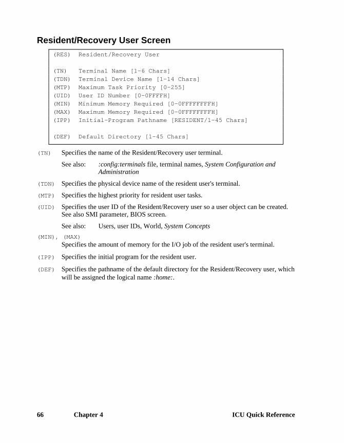
Chapter 4 ICU Quick Reference66
Resident/Recovery User Screen(RES) Resident/Recovery User
(TN) Terminal Name [1-6 Chars]
(TDN) Terminal Device Name [1-14 Chars]
(MTP) Maximum Task Priority [0-255]
(UID) User ID Number [0-0FFFFH]
(MIN) Minimum Memory Required [0-0FFFFFFFFH]
(MAX) Maximum Memory Required [0-0FFFFFFFFH]
(IPP) Initial-Program Pathname [RESIDENT/1-45 Chars]
(DEF) Default Directory [1-45 Chars]
(TN) Specifies the name of the Resident/Recovery user terminal.
See also: :config:terminals file, terminal names, System Configuration andAdministration
(TDN) Specifies the physical device name of the resident user's terminal.
(MTP) Specifies the highest priority for resident user tasks.
(UID) Specifies the user ID of the Resident/Recovery user so a user object can be created.See also SMI parameter, BIOS screen.
See also: Users, user IDs, World, System Concepts
(MIN), (MAX)Specifies the amount of memory for the I/O job of the resident user's terminal.
(IPP) Specifies the initial program for the resident user.
(DEF) Specifies the pathname of the default directory for the Resident/Recovery user, whichwill be assigned the logical name :home:.

ICU User's Guide and Quick Reference Chapter 4 67
Prefixes ScreenThe Prefixes screen is similar to the DOS path command; it enables you to specifywhich directories are searched for HI commands. You can delete the defaults ormove them below your own directories.
(PREF) Prefixes
Prefix = 1-45 Chars
[ 1] Prefix = :PROG:
[ 2] Prefix = :UTILS:
[ 3] Prefix = :UTIL286:
[ 4] Prefix = :SYSTEM:
[ 5] Prefix = :LANG:
[ 6] Prefix = :ICU:
[ 7] Prefix = :$:
[ 8] Prefix =
PrefixSpecifies up to 20 prefixes. Define prefixes you list here on the HILOG screen or inthe SYS parameter on the HI screen.
HI Logical Names Screen:config:, :prog:, and :system: are automatically assigned as logical names. Do notassign them again using this screen.
(HILOG) HI Logical Names
logical_name , path_name
[1-12 Chars] , [1-45 Chars]
[ 1] Name = WORK , :SD:WORK
[ 2] Name = UTILS , :SD:UTIL386
[ 3] Name = UTIL286 , :SD:UTIL286
[ 4] Name = LANG , :SD:LANG286
[ 5] Name = RMX , :SD:RMX386
[ 6] Name = ICU , :SD:RMX386/ICU
[ 6] Name = INCLUDE , :SD:INTEL/INC
[ 7] Name =
logical_nameSpecifies the logical name for the path_name parameter.
path_nameSpecifies the pathname.

Chapter 4 ICU Quick Reference68
Includes and Libraries ScreenThis screen enables you to specify the directory pathnames for libraries, INCLUDEfiles and tools that the ICU references while generating a submit file that assembles,binds, and builds your application system. The names you enter on this screen mustbe logical names surrounded by colons or pathnames ending in a slash.
(INCL) Includes and Libraries [1-30 Chars]
(UDF) UDI Includes and Libs
(HIF) Human Interface Includes and Libs
(EIF) Extended I/O System Includes and Libs
(ALF) Application Loader Includes and Libs
(BIF) Basic I/O System Includes and Libs
(MNF) RadiSys Monitor Includes and Libs
(SDF) System Debugger Includes and Libs
(NUF) Nucleus Includes and Libs
(ILF) Interface Libraries
(DTF) Development Tools Path Name
(VMF) Virtual 8086 Mode includes and libs
(NET) iRMX-NET Files
(CLF) Shared C Libraries
(ISL) RadiSys Support Libraries
(SJM) System Jobs Object Modules
(SJM) INtime Includes and Libraries

ICU User's Guide and Quick Reference Chapter 4 69
(UDF) Specifies the pathname of the directory that contains the UDI files.
(HIF) Specifies the pathname of the directory that contains the HI files.
(EIF) Specifies the pathname of the directory that contains the EIOS files.
(ALF) Specifies the pathname of the directory that contains the AL files.
(BIF) Specifies the pathname of the directory that contains the BIOS files.
(MNF) Specifies the pathname of the directory that contains the RadiSys Monitor files.
(SDF) Specifies the pathname of the directory that contains the System Debugger files.
(NUF) Specifies the pathname of the directory that contains the Nucleus job files.
(ILF) Specifies the pathname of the directory that contains the Interface library files.
(DTF) Specifies the pathname of the directory that contains the Development Tools.
(VMF) Specifies the pathname of the directory that contains the Virtual Mode includes andlibs.
(NET) Specifies the pathname of the directory that contains the iRMX-NET files.
(CLF) Specifies the pathname of the directory that contains the C library files.
(ISL) Specifies the pathname of the directory that contains the floating point supportlibraries.
(SJM) Specifies the pathname of the directory that contains the object modules for thesystem jobs specified in the System Jobs screen (SYSJ).
(ITM) Specifies the pathname of the directory that contains the object modules for theINtime personality files.
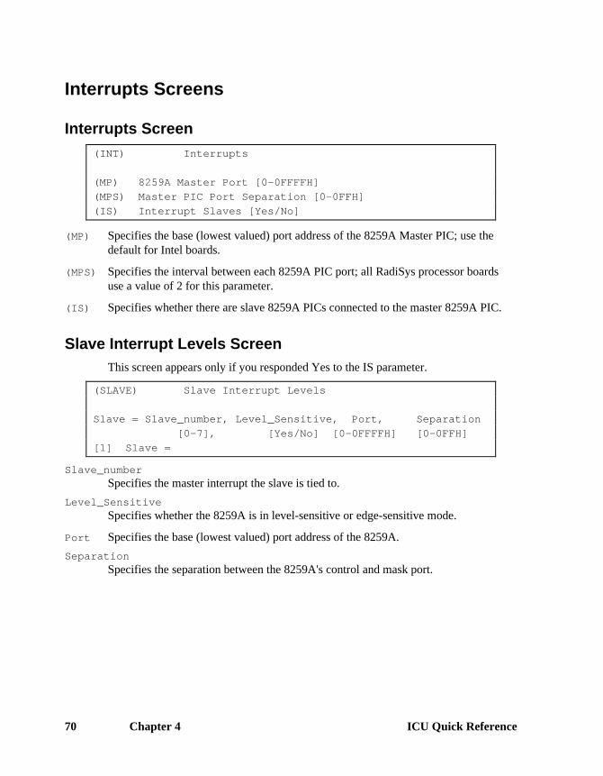
Chapter 4 ICU Quick Reference70
Interrupts Screens
Interrupts Screen(INT) Interrupts
(MP) 8259A Master Port [0-0FFFFH]
(MPS) Master PIC Port Separation [0-0FFH]
(IS) Interrupt Slaves [Yes/No]
(MP) Specifies the base (lowest valued) port address of the 8259A Master PIC; use thedefault for Intel boards.
(MPS) Specifies the interval between each 8259A PIC port; all RadiSys processor boardsuse a value of 2 for this parameter.
(IS) Specifies whether there are slave 8259A PICs connected to the master 8259A PIC.
Slave Interrupt Levels ScreenThis screen appears only if you responded Yes to the IS parameter.
(SLAVE) Slave Interrupt Levels
Slave = Slave_number, Level_Sensitive, Port, Separation
[0-7], [Yes/No] [0-0FFFFH] [0-0FFH]
[1] Slave =
Slave_numberSpecifies the master interrupt the slave is tied to.
Level_SensitiveSpecifies whether the 8259A is in level-sensitive or edge-sensitive mode.
Port Specifies the base (lowest valued) port address of the 8259A.
SeparationSpecifies the separation between the 8259A's control and mask port.

ICU User's Guide and Quick Reference Chapter 4 71
Memory ScreensOnce you have a final system, you can minimize the system memory by changing thevalues on these screens.
See also: Generating and testing the new system in this manual,Adjusting system memory, Programming Techniques and AEDIT TextEditor
Set the lower limit to at least this so the system will boot properly:
Value For System Type6000H or greater MB I (to avoid 3rd Stage BSL)B8000H to C0000H If your boot image has grown, keep this area free for the
MB I 2nd Stage BSL stack (to avoid 1st/3rd stage stacks10000H or greater MB II (to avoid 2nd Stage MSA)0F000H or greater PC Bus Platforms (to avoid the PC 3rd stage)
In addition, do not overlap System or Free Space memory with memory for theseentities. In general, allow the minimum memory you think you will need, then tunethe parameters using output from the builder .mp2 file.
Memory For AddressMSC Device Driver Wakeup 1000H to 1200H
Addresses and Wakeup BlocksROM-based systems Address specified in RIARAM driver Address specified in BMAI/O Controller Address specified in IPA, MA, BBA, etc.
Start MEMSStart MEMF
When calculating the system memory requirements, also consider the memoryrequired by the subsystems and your embedded applications.
See also SUB screen description for memory required for subsystems

Chapter 4 ICU Quick Reference72
Memory for System Screen(MEMS) Memory for System
SYS = low [0-0FFFFFFFFH], high [0-0FFFFFFFFH]
[ 1] SYS =
low, highSpecify the start and end addresses of each contiguous memory block (32-bit physicalmemory location) to reserve for code and data segments.
Memory for Free Space Manager Screen(MEMF) Memory for Free Space Manager
FSM = low [0-0FFFFFFFFH], high [0-0FFFFFFFFH]
[ 1] FSM =
low, highSpecify the start and end addresses of each contiguous block (32-bit physical memorylocation) of memory to reserve for dynamic allocation.
Do not overlap memory you reserved in the MEMS screen.
Paging Identity Mapped Memory Screen(PIMM) Paging Identity Mapped Memory
IMM = low [0-0FFFFFFFFH], high [0-0FFFFFFFFH]
[ 1] IMM =
low, highSpecify the start and end addresses of each contiguous block (32-bit physical memorylocation) of memory you want identified with the Paging Subsystem.
Do not enter any memory areas that have been previously reserved for use by theFSM or the system.

ICU User's Guide and Quick Reference Chapter 4 73
Network Screens
Network Subsystem ScreenUse this screen to configure the parameters for the Networking Subsystem.
(NET) Network Subsystem
(MIP) iNA 960 MIP Driver Job [Yes/No]
(CMP) iNA 960 COMMputer Job [Yes/No]
(RCJ) iRMXNET Client Job [Yes/No]
(RSJ) iRMXNET Server Job [Yes/No]
(TCP) iRMX TCP/IP Job [Yes/No]
(XSJ) X25 Server Job [Yes/No]
(XCJ) X25 Client Job [Yes/No]
(MIP) Specifies whether to configure the iNA 960 MIP Driver Job into the OS.
(CMP) Specifies whether to configure the iNA 960 COMMputer Job into the OS.
(RCJ) Specifies whether to configure the iRMX-NET client job into the OS.
(RSJ) Specifies whether to configure the iRMX-NET server job into the OS.
(TCP) Specifies whether to configure the TCP/IP job into the OS.
(XSJ) Specifies whether to configure the X.25 server job into the OS.
(XCJ) Specifies whether to configure the X.25 client job into the OS.

Chapter 4 ICU Quick Reference74
iNA MIP Driver Job ScreenThis screen appears if you specify MIP on the NET screen.
(IMIPJ) iNA MIP Driver Job
(ODS) Object Directory Size [0-3840]
(PMI) Pool Minimum [60H-0FFFFFFFH]
(PMA) Pool Maximum [60H-0FFFFFFFH]
(MOB) Maximum Objects [1-0FFFFH]
(MTK) Maximum Tasks [1-0FFFFH]
(MPR) Maximum Priority [0-255]
(PV) Parameter Validation [Yes/No]
(TP) Task Priority [0-255]
(SSI) Stack Size [0-0FFFFH]
(NPX) Numeric Processor Extension Used [Yes/No]
(MJN) Name of MIP Job to be generated [1-45 Chars]
(CLJ) Create Loadable Job [Yes/No]
(NL) iNA Network Layer [0/1/2/3]
(CET) COMMengine Type [1=MBI/2=MBII/3=AT]
(ODS) Specifies in decimal the maximum number of entries in this job's object directory; 0means create no directory.
(PMI), (PMA)Specifies in 16-byte paragraphs the minimum and maximum sizes of this job'smemory pool.
(MOB) Specifies how many objects can exist simultaneously in the job; 0FFFFH means nolimit to the number of created objects.
(MTK) Specifies how many tasks can exist simultaneously in this job.
(MPR) Specifies in decimal the highest priority of tasks in this job.
(PV) Specifies whether to include parameter validation for Nucleus system calls made bytasks in this job, if you included system-level parameter validation.
(TP) Specifies in decimal the priority of this job's initialization task.
(SSI) Specifies in bytes the size of the initialization task's stack segment, according to yoursegmentation model.
(NPX) Specifies if the job's initial task contains floating-point instructions.
(MJN) Specifies the name of the generated MIP job.

ICU User's Guide and Quick Reference Chapter 4 75
(CLJ) Specifies whether to generate a separate job that can be loaded by sysload or bind thejob with the boot image.
(NL) Specifies the type of network layer configured in the iNA Transport Software.
(CET) Specifies the type of COMMengine.
MIP Configuration for Multibus I ScreenUse this screen to configure the MIP job in a COMMengine hardware environmenton a Multibus I system.
(MIP1) MIP Configuration for MBI
(CBN) Communication Board Name [1-20 Chars]
(NEM) Number of External Mailboxes [1-0FFFFH]
(RQB) Request Queue Addr Base [0-0FFFFH]
(RQO) Request Queue Addr Offset [0-0FFFFH]
(WP) Wakeup Port [0-0FFFFH]
(IL) Interrupt Level [0-0FFH]
(LD) Load [L/R/P/N]
(DN) Device Name [1-14 Chars]
(FN) File Name [1-30 Chars]
(CC) Class Code [0-0FFFFH]
(HBA) Host Buffer Address [0-0FFFFFH]
(BAB) Boot Address Base [0-0FFFFH]
(BAO) Boot Address Offset [0-0FFFFH]
(CSB) Comm Start Address Base [0-0FFFFH]
(CSO) Comm Start Address Offset [0-0FFFFH]
(CD) COMMengine Delay [0-0FFFFH]
(CBN) Specifies the name of the NIC used as a communication board by the MIP job.
(NEM) Specifies how many unique response mailboxes applications can have in requestblocks at any given time.
(RQB) Specifies the address base for the start of communication request buffers.
(RQO) Specifies the address offset for the start of communication request buffers.
(WP) Specifies the I/O port that the COMMengine recognizes.
(IL) Specifies which one of the eight MB encoded interrupt levels that the COMMengineboard uses to signal messages to the iRMX system.
(LD) Specifies how the COMMengine is loaded with the iNA Transport Software.
(DN) Specifies the device name where the iNA software resides.
Chapter 4 ICU Quick Reference76
(FN) Specifies the pathname of the load file.
(CC) Specifies the class code that the COMMengine uses when requesting a boot service.
(HBA) Specifies the absolute address of the 180DH byte host buffer where the COMMsoftware will be located for the firmware to load.
(BAB) Specifies the base portion of the address of one of eight addresses from which theCOMMengine gets its boot commands.
(BAO) Specifies the offset portion of the address of one of eight addresses from which theCOMMengine gets its boot commands.
(CSB) Specifies the base portion of the start address of the communication software on theCOMMengine, if iNA is in PROM.
(CSO) Specifies the offset portion of the start address of the communication software on theCOMMengine, if iNA is in PROM.
(CD) Specifies how many Nucleus clock ticks the software executing on the host processorwaits so that the iNA Transport Software running on the communications board cancomplete initialization.

ICU User's Guide and Quick Reference Chapter 4 77
MIP Configuration for Multibus II ScreenUse this screen to configure the MIP job in a COMMengine hardware environmenton a Multibus II system.
(MIP2) MIP Configuration for MBII
(PID) COMM Port ID [0-0FFFFH]
(NEM) Number of External Mailboxes [10-65535]
(RDT) Response Delay Time [1-0FFFFH]
(NLB) Number of Large Buffers [2-65535]
(LBS) Large Buffer Size [2048-65535]
(NSB) Number of Small Buffers [10-65535]
(SBS) Small Buffer Size [256-2048]
(CD) COMMengine Delay [0-0FFFFH]
(QS) Queue Size [1-65535]
(PID) Specifies the MB II Port ID at which the iNA 960 Transport Software is listening forrequests.
See also: Network User's Guide and Reference
(NEM) Specifies how many unique response mailboxes applications can have in requestblocks at any given time.
(RDT) Specifies how many Nucleus clock ticks to wait for a response from the software onthe communication board.
(NLB) Specifies how many large buffers MIP will create and release to the buffer pool.
See also: Buffer pools, System Concepts
(LBS) Specifies in bytes the size of each large buffer created by an rq_create_segmentsystem call.
(NSB) Specifies how many small buffers MIP will create and release to the buffer pool.
(SBS) Specifies in bytes the size of each small buffer created by an rq_create_segmentsystem call.
(CD) Specifies how many Nucleus clock ticks the software executing on the host processorwaits so that the iNA Transport Software running on the communications board cancomplete initialization.
(QS) Specifies how many MB II messages the OS will queue at the receive port.

Chapter 4 ICU Quick Reference78
COMMengine Board Instance Load Method for MBII ScreenUse this screen to specify the iNA 960 file to load on a particular COMMengine NICand to specify the load method.
(CEBI) COMMengine Board Instance Load Method for MBII
(CBI) Comm. Board Instance [0-19]
(LD) Load [L/P/N]
(DN) Device Name [1-14 Chars]
(FN) File Name [1-30 Chars]
(CC) Class Code [0-0FFFFH]
(CBI) Specifies the Ethernet board instance to which the other parameters refer.
(LD) Specifies how the COMMengine is loaded with the iNA Transport Software.
(DN) Specifies the device name where the iNA Transport Software resides.
(FN) Specifies the pathname of the load file.
(CC) Specifies the class code the COMMengine uses when requesting a boot service.
COMMengine Board Names ScreenUse this screen to specify all possible boards used as COMMengine NICs on theMultibus II backplane.
(CEBN) COMMengine Board Names
CEBN = 1-20 characters
[]CEBN =
(CEBN) Specifies the boards used as COMMengine NICs.

ICU User's Guide and Quick Reference Chapter 4 79
MIP Configuration for PC Bus ScreenUse this screen to configure the MIP job in a COMMengine hardware environmenton a PC.
(MIPAT) MIP Configuration for PC Bus
(CBN) Communication Board Name [1-20 Chars]
(NEM) Number of External Mailboxes [0-0FFFFH]
(WP) Wakeup Port [0-0FFFFH]
(IL) Interrupt Level [0-0FFH]
(LD) Load [L/P/N]
(DN) Device Name [1-14 Chars]
(FN) File Name [1-30 Chars]
(CC) Class Code [0-0FFFFH]
(BAB) Boot Address Base [0-0FFFFH]
(BAO) Boot Address Offset [0-0FFFFH]
(CD) COMMengine Delay [0H-0FFFFH]
(CBN) Specifies the name of the Ethernet board used by the MIP job.
(NEM) Specifies the maximum number of unique response mailboxes that iRMXapplications can have in request blocks at any given time.
(WP) Specifies the I/O port that the PCL2 COMMengine recognizes.
(IL) Specifies the encoded interrupt level that the iRMX system receives from the PCL2COMMengine board.
(LD) Specifies how the COMMengine is loaded with the iNA Transport Software.
(DN) Specifies the device name where the iNA software resides.
(FN) Specifies the pathname of the load file.
(CC) Specifies the class code that the COMMengine uses when requesting a boot service.
(BAB) Specifies the base portion of the address of one of eight addresses from which theCOMMengine gets its boot commands.
See also: Network User's Guide and Reference for further information aboutconfiguring the COMMengine boot address
(BAO) Specifies the offset portion of the address of one of eight addresses from which theCOMMengine gets its boot commands.
(CD) Specifies the number of Nucleus clock ticks that the software executing on the hostprocessor waits so that the iNA Transport Software running on the communicationsboard can complete initialization.

Chapter 4 ICU Quick Reference80
iNA 960 COMMputer Job ScreenThis screen appears if you specify CMP on the NET screen.
(ICMPJ) iNA 960 COMMputer Job
(ODS) Object Directory Size [0-3840]
(PMI) Pool Minimum [60H-0FFFFFFFH]
(PMA) Pool Maximum [60H-0FFFFFFFH]
(MOB) Maximum Objects [1-0FFFFH]
(MTK) Maximum Tasks [1-0FFFFH]
(MPR) Maximum Priority [0-255]
(PV) Parameter Validation [Yes/No]
(TP) Task Priority [0-255]D
(SSI) Stack Size [0-0FFFFH]
(NPX) Numeric Processor Extension Used [Yes/No]
(OFN) Object Module File Name [1-45 Chars]
(CLJ) Create Loadable Job [Yes/No]
(NL) iNA Network Layer [0/1/2/3]
(SN1) iNA Subnet 1 ID [0-0FFFFH]
(SN2) iNA Subnet 2 ID [0-0FFFFH]
(SN3) iNA Subnet 3 ID [0-0FFFFH]
(SN4) iNA Subnet 4 ID [0-0FFFFH]
(ODS) Specifies in decimal the maximum number of entries in this job's object directory; 0means create no directory.
(PMI), (PMA)Specifies in 16-byte paragraphs the minimum and maximum sizes of this job'smemory pool.
(MOB) Specifies how many objects can exist simultaneously in the job; 0FFFFH means nolimit to the number of created objects.
(MTK) Specifies how many tasks can exist simultaneously in this job.
(MPR) Specifies in decimal the highest priority of tasks in this job.
(PV) Specifies whether to include parameter validation for Nucleus system calls made bytasks in this job, if you included system-level parameter validation.
(TP) Specifies in decimal the priority of this job's initialization task.
(SSI) Specifies in bytes the size of the initialization task's stack segment, according to yoursegmentation model.
(NPX) Specifies if the job's initial task contains floating-point instructions.

ICU User's Guide and Quick Reference Chapter 4 81
(OFN) Specifies the pathname of the object module for the job.
(CLJ) Specifies whether to generate a separate job loadable by sysload or generate and bindthe job with the system boot image.
(NL) Specifies the type of network layer configured in the iNA Transport Software.
(SN1) Specifies the subnet ID of the first subnet configured in the job.
(SN2) Specifies the subnet ID of the second subnet configured in the job.
(SN3) Specifies the subnet ID of the third subnet configured in the job.
(SN4) Specifies the subnet ID of the fourth subnet configured in the job.
iRMX-NET Client Job ScreenUse this screen to configure the parameters for the iRMX-NET client job and remotefile driver.
(RCJ) iRMX-NET Client Job
(ODS) Object Directory Size [0-3840]
(PMI) Pool Minimum [60H-0FFFFFFFH]
(PMA) Pool Maximum [60H-0FFFFFFFH]
(MOB) Maximum Objects [1-0FFFFH]
(MTK) Maximum Tasks [1-0FFFFH]
(MPR) Maximum Priority [0-255]
(PV) Parameter Validation [Yes/No]
(TP) Task Priority [0-255]
(SSI) Stack Size [0-0FFFFH]H
(NPX) Numeric Processor Ext. Used [Yes/No]
(CLJ) Create Loadable Job [Yes/No]
(CBN) COMM Board Name [1-20 Chars]
(CBI) COMM Board Instance [0-20]
(COS) Connection Object Size [0-255]
(ISS) I/O Task Stack Size [0-65534]
(ITP) I/O Task Priority [0-255]
(DDS) Device Descriptor Size [0-255]
(EBS) EIOS Buffer Size [0-0FFFFH
(DRQ) DUIBs Required [Yes/No]
(IRD) iNA Ready Delay [0-65534]
(ODS) Specifies in decimal how many entries can be in this job's object directory.
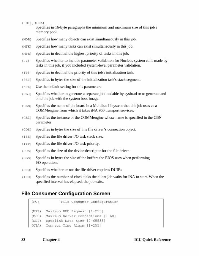
Chapter 4 ICU Quick Reference82
(PMI),(PMA)Specifies in 16-byte paragraphs the minimum and maximum size of this job'smemory pool.
(MOB) Specifies how many objects can exist simultaneously in this job.
(MTK) Specifies how many tasks can exist simultaneously in this job.
(MPR) Specifies in decimal the highest priority of tasks in this job.
(PV) Specifies whether to include parameter validation for Nucleus system calls made bytasks in this job, if you included system-level parameter validation.
(TP) Specifies in decimal the priority of this job's initialization task.
(SSI) Specifies in bytes the size of the initialization task's stack segment.
(NPX) Use the default setting for this parameter.
(CLJ) Specifies whether to generate a separate job loadable by sysload or to generate andbind the job with the system boot image.
(CBN) Specifies the name of the board in a Multibus II system that this job uses as aCOMMengine from which it takes iNA 960 transport services.
(CBI) Specifies the instance of the COMMengine whose name is specified in the CBNparameter.
(COS) Specifies in bytes the size of this file driver’s connection object.
(ISS) Specifies the file driver I/O task stack size.
(ITP) Specifies the file driver I/O task priority.
(DDS) Specifies the size of the device descriptor for the file driver
(EBS) Specifies in bytes the size of the buffers the EIOS uses when performingI/O operations
(DRQ) Specifies whether or not the file driver requires DUIBs
(IRD) Specifies the number of clock ticks the client job waits for iNA to start. When thespecified interval has elapsed, the job exits.
File Consumer Configuration Screen(FC) File Consumer Configuration
(MRR) Maximum RFD Request [1-255]
(MSC) Maximum Server Connections [1-60]
(DDS) Datalink Data Size [2-65535]
(CTA) Connect Time Alarm [1-255]

ICU User's Guide and Quick Reference Chapter 4 83
(STA) Send Time Alarm [1-255]
(MRR) Specifies in decimal how many outstanding RFD requests can exist simultaneously.
(MSC) Specifies in decimal how many servers can connect as remote devices to thisconsumer at any given time.
(DDS) Specifies in decimal how many bytes to deliver in one full data link packet.
(CTA) Specifies how many seconds the File Consumer waits for a server connection.
(STA) Specifies how many seconds the File Consumer waits for a server to respond to arequest.
Remote File Access ScreenUse this screen to configure the iRMX-NET client job and remote file driver (RFD).
(REM) Remote File Access
(ITP) I/O Task Priority [0-255]
(NOR) Number of Outstanding RFD system calls [0-255]
(NOS) Number of Outstanding RFD status calls [0-255]
(JEI) Job Exit Interval [0-0FFFFFFFFH]
(LI) Logoff Interval [0-0FFFFFFFF]
(CBT) Configuration Base Time [0-0FFFFFFFFH]
(ITP) Specifies in decimal the priority of the two RFD service tasks created.
(NOR) Specifies in decimal the average number of simultaneous outstanding RFD systemcalls.
(NOS) Specifies the average number of simultaneous outstanding RFDa_get_connection_status, a_get_file_status, and a_get_extension_data systemcalls.
(JEI) Specifies, in units of Nucleus clock ticks multiplied by 1024, how long the RFD waitsto delete resources after a job detaches its last connection to files residing on a remotefile server.
(LI) Specifies the logout interval for the Remote File Driver.
(CBT) Specifies how many seconds from midnight January 1, 1978 (the RFD fixed point) tothe fixed point used by your system.

Chapter 4 ICU Quick Reference84
iRMX-NET Server Job ScreenUse this screen to configure the parameters for the iRMX-NET server job and remotefile driver.
(RSJ) iRMX-NET Server Job
(ODS) Object Directory Size [0-3840]
(PMI) Pool Minimum [60H-0FFFFFFFH]
(PMA) Pool Maximum [60H-0FFFFFFFH]
(MOB) Maximum Objects [1-0FFFFH]
(MTK) Maximum Tasks [1-0FFFFH]
(MPR) Maximum Priority [0-255]
(PV) Parameter Validation [Yes/No]
(TP) Task Priority [0-255]
(SSI) Stack Size [0-0FFFFH]H
(NPX) Numeric Processor Ext. Used [Yes/No]
(CLJ) Create Loadable Job [Yes/No]
(CBN) COMM Board Name [1-20 Chars]
(CBI) COMM Board Instance [0-20]
(IRD) iNA Ready Delay [0-65534]
(ODS) Specifies in decimal how many entries can be in this job's object directory.
(PMI),(PMA)Specifies in 16-byte paragraphs the minimum and maximum size of this job'smemory pool.
(MOB) Specifies how many objects can exist simultaneously in this job.
(MTK) Specifies how many tasks can exist simultaneously in this job.
(MPR) Specifies in decimal the highest priority of tasks in this job.
(PV) Specifies whether to include parameter validation for Nucleus system calls made bytasks in this job, if you included system-level parameter validation.
(TP) Specifies in decimal the priority of this job's initialization task.
(SSI) Specifies in bytes the size of the initialization task's stack segment.
(NPX) Use the default setting for this parameter.

ICU User's Guide and Quick Reference Chapter 4 85
(CLJ) Specifies whether to generate a separate job loadable by sysload or to generate andbind the job with the system boot image.
(CBN) Specifies the name of the board in a Multibus II system that this job uses as aCOMMengine from which it takes iNA 960 transport services.
(CBI) Specifies the instance of the COMMengine whose name is specified in the CBNparameter.
(IRD) Specifies the number of clock ticks which the server job waits for iNA to start. Afterthe interval elapses, the job exits.
File Server Configuration ScreenUse this screen to configure the iRMX-NET File Server job.
(FS) File Server Configuration
(VC) Number of Virtual Circuits [1-60]
(UVC) Number of Users per VC [1-255]
(PVC) Number of Processes per VC [1-255]
(BVC) Number of Binds per VC [1-255]
(OFV) Number of Open Files per VC [1-255]
(OFP) Number of Open Files per process [1-255]
(SC) Server Concurrency [1-80]
(FSN) File Server Name [NONE/1-16 Chars]
(VC) Specifies in decimal how many virtual circuits can be used by the File Server, whichdetermines how many client systems can concurrently access the File Server.
(UVC) Specifies in decimal how many distinct users can access a server from the same clientsystem at the same time, as limited by the space in the File Server's data segment.
(PVC) Specifies in decimal how many jobs (client processes) can concurrently access avirtual circuit, as limited by the space in the File Server's data segment.
(BVC) Specifies in decimal how many file attaches a client system has on the server at anygiven time, as limited by the space in the File Server's data segment.
(OFV) Specifies in decimal how many opened server files a client can have at any giventime.
(OFP) Specifies in decimal how many files a job (client process) can have open.
(SC) Specifies in decimal how many outstanding requests the File Server can process atany given time.
(FSN) Specifies the name of the File Server.

Chapter 4 ICU Quick Reference86
Apex File Access Screen(AFA) Apex File Access
(MDV) Max number of Public Devices [1-20]
(MPD) Max number of Public Dirs [1-64]
(NAT) Number of AFA tasks [1-60]
(ATT) Attributes [Yes/No]
(DPD) Dynamic Public dirs [Yes/No]
(WD) Wildcard Delete [Yes/No]
(WFS) Wildcard File Search [1-255]
(WTI) Wildcard Wait Interval [0-65535]
(PSC) Print Spooler Commands [Yes/No]
(MDV) Specifies in decimal how many devices may contain public directories.
(MPD) Specifies in decimal how many public directories on the server can be accessed byremote systems.
(NAT) Specifies in decimal how many I/O requests the File Server can service at any giventime.
(ATT) Specifies if special UNIX or DOS file attributes are required.
(DPD) Specifies whether to add new public directories when the iRMX-NET system isrunning.
(WD) Specifies whether to allow wildcard notation in deleting remote files.
(WFS) Specifies in decimal how many file searches iRMX-NET can concurrently supportwhile performing searches.
(WTI) Specifies in decimal units of Nucleus clock ticks how long iRMX-NET holds a fileconnection while performing searches.
(PSC) Specifies whether to include the Print Spooler Commands in the File Server.

ICU User's Guide and Quick Reference Chapter 4 87
AFA User ScreenThis screen appears only if you enable the iRMX-NET server; use it to specify thecharacteristics of the server’s internal AFA User.
(AFAU) AFA User
(USS) User Subsystem [0-0FFH]
(NRB) Number of RBs [1-0FFH]
(EDF) Extension Data Field [0-255]
(NSB) Number of Small Buffers [2-255]
(SBS) Small Buffer Size [2-65535]
(NBB) Number of Large Buffers [1-255]
(BBS) Large Buffer Size [2-65535]
(NCB) Number of Command Buffers [1-255]
(CBS) Command Buffer Size [2-65535]
(USS) Specifies the AFA subsystem.
(NRB) Specifies how many requests an AFA user can make to AFA at the same time.
(EDF) Set to 0.
(NSB) Specifies in decimal how many small data buffers to place into one iRMX segment.
(SBS) Specifies in bytes the size of the small data buffers that hold the data sent betweensystems during read and write operations.
(NBB) Specifies in decimal how many large data buffers to place into one iRMX segment.
(BBS) Specifies in bytes the size of the large buffers used to hold the data that is sentbetween systems during read and write operations.
(NCB) Specifies in decimal how many command buffers to use.
(CBS) Specifies in bytes the size of the command buffers.

Chapter 4 ICU Quick Reference88
Public Devices ScreenThis screen specifies which devices in a local system can contain directories availablefor public use. Entries vary depending on the bus type.
(PDEV) Public Devices
PDEV = Logical Name, Device Name , File Driver, Who Attaches
[1-12 Chars], [1-14 Chars] , [N/P/S/E/D],
[Rmxnet/Eios]
[1] PDEV = SD , , NAMED , EIOS
[2] PDEV = BB , BB , PHYSICAL , EIOS
[3] PDEV =
Logical NameSpecifies the logical name of the device that contains public directories.
Device NameSpecifies the name of the particular physical device that contains public directories.
File DriverSpecifies the file driver associated with the device.
Who AttachesSpecifies whether iRMX-NET or EIOS attaches the physical device; use the EIOS toattach public devices so you can delete them with the detachdevice command or thelogical_detach_device system call.

ICU User's Guide and Quick Reference Chapter 4 89
Public Directory ScreenThe maximum number of entries in this screen is determined by the maximumnumber of public directories specified in the AFA screen. Entries vary depending onthe bus type.
(PDIR) Public Directory
PDIR = Logical name, Actual name , Public name
[1-12 Chars], [1-33 Chars], [1-14 Chars]
[ 1] PDIR = SD , WORK , WORK
[ 2] PDIR = SD , , SD
[ 3] PDIR = BB , , BB
[ 4] PDIR = SD , LANG286 , LANG286
[ 5] PDIR = SD , SYS386 , SYS386
[ 6] PDIR = SD , UTIL386 , UTIL386
[ 7] PDIR = SD , UTIL286 , UTIL286
[ 8] PDIR = SD , USER , USER
[ 9] PDIR = SD , RMX286 , RMX286
[10] PDIR = SD , RMX386 , RMX386
[11] PDIR = SD , BOOT32 , BOOT32
[12] PDIR = SD , NET , NET
[13] PDIR = SD , INC , INC
[14] PDIR = SD , LIB , LIB
[15] PDIR = SD , RBOOT32 , RBOOT32
[16] PDIR = SD , MSA , MSA
[17] PDIR = SD , MSA32 , MSA32
[18] PDIR = SD , BSL , BSL
[19] PDIR = SD , HELPS , HELPS
[20] PDIR =
[20] PDIR =
Logical nameSpecifies the logical name of the device as cataloged in the root directory thatcontains the public directory and as defined in a PDEV screen.
Actual nameSpecifies the pathname of the directory, starting from the root of the public device.
Public nameSpecifies the public directory name that a client sees when accessing this server.

Chapter 4 ICU Quick Reference90
User Definition File Screen(UDF) User Definition File
(MUL) Master UDF Location [Named/Remote]
(MLN) Master UDF Logical Name [1-12 Chars]
(MPN) Master UDF Path Name [1-45 Chars]
(MD) Master UDF Device [1-14 Chars]
(LUL) Local UDF Location [Named/Edos/Dos/Unused]
(LLN) Local UDF Logical Name [1-12 Chars]
(LPN) Local UDF Path Name [1-45 Chars]
(LD) Local UDF Device [1-14 Chars]
(UPD) Update UDF [0-0FFFFH]
(WV) Who Verifies [Eios/Rmxnet]
(WA) Who Attaches [Eios/Rmxnet]
(ALN) Automatic Loadname [Yes/No]
(MUL) Specifies the location of the Master UDF.
(MLN) Specifies the logical name assigned to the device where the Master UDF resides.
(MPN) Specifies the pathname of the Master UDF.
(MD) Specifies the device name according to the location of the Master UDF that the UserAdministration module must physically attach.
(LUL) Specifies the physical location of the local UDF.
(LLN) Specifies the logical name of the device where the local UDF resides.
(LPN) Specifies the pathname of the local UDF.
(LD) Specifies the name of the device where the local UDF resides.
(UPD) Specifies how many seconds the User Administration module waits between updatesof the local UDF from the Master UDF.
(WV) Specifies whether iRMX-NET verifies users or uses the rq_verify_user system call.
(WA) Specifies whether iRMX-NET or the EIOS attaches the system device.
(ALN) Specifies whether iRMX-NET should initialize the Name Server Database.

ICU User's Guide and Quick Reference Chapter 4 91
Client Definition File Screen(CDF) Client Definition File
(CLC) CDF Location [Named/Remote]
(CLN) CDF Logical Name [1-12 Chars]
(CPN) CDF Path Name [1-45 Chars]
(CDD) CDF Device [1-14 Chars]
(CNN) Client Name [1-8 Chars]
(CNP) Client Password [1-8 Chars]
(CIB) Client Info Addr Base [0-0FFFFH]
(CIO) Client Info Addr Offset [0-0FFFFH]
(CLC) Specifies the location of the CDF file.
(CLN) Specifies the logical name assigned to the device where the CDF resides; use allUPPERCASE letters.
(CPN) Specifies the pathname of the CDF file.
(CDD) Specifies the name of the device where the CDF resides.
(CNN) Specifies the name of the client system.
(CNP) Specifies the password of the client system.
(CIB) Specifies the base portion of the absolute memory address where the client system'sname and password are placed.
(CIO) Specifies the offset portion of the absolute memory address where the client system'sname and password are placed.

Chapter 4 ICU Quick Reference92
Name Server Configuration ScreenThis screen appears only if you specify a COMMputer job on the NET screen.
(NS) Name Server Configuration
(NO) Maximum Number of Objects [2-246]
(PVL) Maximum Property Value Length [20-255]
(MC1) Multicast Address 1 [0-0FFH]
(MC2) Multicast Address 2 [0-0FFH]
(MC3) Multicast Address 3 [0-0FFH]
(MC4) Multicast Address 4 [0-0FFH]
(MC5) Multicast Address 5 [0-0FFH]
(MC6) Multicast Address 6 [0-0FFH]
(ITI) Initiator TSAP ID [0-0FFFFH]
(RTI) Responder TSAP ID [0-0FFFFH]
(FST) File Server TSAP ID [0-0FFH]
(FCT) File Consumer TSAP ID [0-0FFH]
(RET) Retry Timeout [0-0FFFFH]
(NR) Maximum Number of Retries [0-255]
(RSP) Maximum Number of Responses [1-255]
(LO) Name Server Local Only [Yes/No]
(NO) Specifies in decimal how many objects can be entered into the local object table, notincluding objects that iRMX-NET loads into the local object table duringinitialization.
(PVL) Specifies in decimal the maximum length of the property value.
(MC1) - (MC6)Specifies the first through the sixth bytes of the multicast address that the NameServer uses to transmit Name Server queries over the network.
(ITI) Specifies the Transport Service Access Point Identification (TSAP-ID) the initiator ofName Server queries uses.
(RTI) Specifies the TSAP-ID for the Name Server Responder.
(FST) Specifies the TSAP-ID for the File Server.
(FCT) Specifies the TSAP-ID for the File Consumer.

ICU User's Guide and Quick Reference Chapter 4 93
(RET) Specifies in 100 microsecond increments the time interval for the Name Server towait before trying a request to a remote network system.
(NR) Specifies how many times a request is retransmitted by the Name Server before beingdiscontinued.
(RSP) Specifies how many responses can be handled by the Name Server for a request.
(LO) Specifies whether the Name Server supports local operations only and cannot accessremote object tables to retrieve property values or execute other functions.
Name Server Search Domains ScreenUse this screen to configure subnet IDs to be searched by the Name Server in asystem where you use an iNA 960 job with an ES-IS network layer.
(NSDOM) Name Server Search Domains
DOM = Subnet I.D.
[0-0FFFFH]
[] DOM =
(DOM) Specifies up to twenty subnet IDs to be searched by the Name Server.

Chapter 4 ICU Quick Reference94
Nucleus Screens
Nucleus Screen(NUC) Nucleus
(NGE) Number of GDT Entries [440-8190]
(NIE) Number of IDT Entries [0-256]
(PV) Parameter Validation [Yes/No]
(ROD) Root Object Directory Size [0-3840]
(DSH) Default Software Exception Handler [Job/Task/STask/User]
(EM) Exception Mode [Never/Program/Environ/All]
(NEH) Name of Ex Handler Object Module [1-55 Chars]
(DHH) Default Hardware Exception Handler [Job/Task/STask/Monitor]
(HER) Hardware Exception Reporting [Yes/No]
(NMI) NMI Exception Handler [Yes/No/Ignore/Job/SDM/User]
(NEB) NMI Enable Byte [0-255]
(LSE) Low GDT/LDT Slot Excluded from FSM [440-8189/NONE=0]
(HSE) High GDT/LDT Slot Excluded from FSM [440-8189/NONE=0]
(RRP) Round Robin Priority Threshold [0-255]
(RRT) Round Robin Time Quota [0-255]
(RIE) Report Initialization Errors [Yes/No]
(MCE) Maximum Data Chain Elements [0-0FFFFH]
(CS) Nucleus Communication Service [Yes/No]
(MS) Nucleus Messaging Service [Yes/No]
✏ NoteIf you use an iNA 960 MIP job in a Multibus II system, you mustexclude GDT slots 4096 through 4767. Set LSE to 4096 and HSEto 4767.
(NGE) Specifies in decimal the number of objects in your system, since each object musthave a descriptor in the GDT. Add 16 bytes for each entry to required memory onthe MEMS screen.
(NIE) Specifies in decimal the number of entries in the IDT.
(PV) Specifies whether system-level parameter validation occurs.
See also: Parameter validation, System Call Reference
(ROD) Specifies in decimal how many entries can exist in the root job's object directory.
(DSH) Specifies the system’s default exception handler.

ICU User's Guide and Quick Reference Chapter 4 95
See also: Exception handlers, System Concepts
(EM) Specifies the exception mode of the default system exception handler.
(NEH) Specifies the pathname of the exception handler object module output by BND386, ifyou specified User for the DSH parameter.
(DHH) Specifies the system’s default hardware exception handler.
(HER) Determines whether the exception handling mailbox is created and hardwareexceptions are reported to it. If you select Yes, the data mailbox is created andcataloged under the name HW_FAULT_MBX in the root job.
(NMI) Specifies how an NMI exception is handled.
(NEB) (MBII only) Specifies the NMI interrupt source(s) to be enabled.
(LSE), (HSE)Specifies in decimal the range additional GDT/LDT slots to reserve for first-leveluser jobs and I/O jobs, in addition to the default of approximately 350 slots.
(RRP) Specifies in decimal the priority below which tasks will be assigned round-robinscheduling.
See also: Round-robin scheduling, Introducing the iRMX Operating Systems
(RRT) Specifies in decimal the time, in Nucleus clock ticks, each task is allowed to runbefore the Nucleus transfers control to a waiting task with the same priority. See alsoCIN.
(RIE) Specifies whether initialization errors for all iRMX layers are displayed at themonitor console as a hexadecimal code and a mnemonic.
(MCE) Specifies how many elements can exist in a single DMA data chain.
See also: Data chains, System Concepts
(CS) Specifies whether to include the Nucleus Communication Service.
(MS) Specifies whether to configure the Nucleus Messaging Service. If theCommunication Service is configured, this parameter must be set to No.

Chapter 4 ICU Quick Reference96
Nucleus Communication Service Screen
Use this screen to configure the Nucleus Communication Service parameters.
(NTS) Nucleus Communication Service
(PMT) Message Task Priority [0-255]
(DPT) Default Number of Port Transactions [0-255]
(MSM) Max. No. of Simultaneous Messages [0-0FFFFH]
(MST) Max. No. of Simultaneous Transactions [0-0FFFFH]
(RFT) Receive Fragment Failsafe Timeout [0-0FFFFH]
(PMT) Specifies in decimal the priority of the Nucleus Communications Service messagetask, which runs when a solicited message is received. Tasks that deal with I/Otypically have priorities set around 128 through 131.
(DPT) Specifies in decimal a default number of simultaneous port transactions. This valueis used when an rq_create_port system call is issued with a zero in thenum_trans field.
(DHI) Specifies in decimal the message address of each board in a MB II system that needsto pass messages.
(MSM) Specifies the maximum number of simultaneous messages in the system. Eachmessage sent, either solicited or unsolicited, has a control portion that is placed inbuffer space taken from the root job. When all the buffer space is used, an error isreturned.
(MST) Specifies the maximum number of simultaneous transactions in the system. Eachtransaction requires buffer space from the root job. When all the buffer space is used,an error is returned.
(RFT) Specifies, in 10-millisecond clock ticks, the receive_fragment system call timevalue. If an rq_receive_fragment system call is issued, this parameter specifies howlong the calling task waits for a message fragment. The value 0FFFFh specifies waitforever.

ICU User's Guide and Quick Reference Chapter 4 97
Nucleus Messaging Service ScreenUse this screen to configure the Nucleus Messaging Service parameters.
(NMS) Nucleus Messaging Service
(PDT) Deletion Task Priority [0-255]
(VBP) Validate Buffer Parameters [Yes/No]
(PDT) Specifies in decimal the Port Deletion Task priority. The management of ports(creation and deletion) should typically have a higher priority than your ownapplications.
(VBP) Determines whether the buffer parameter validation should be performed. Whenevera system call that contains a pointer to a buffer is issued, the Nucleus can check toensure that the pointer is valid, and that the buffer is large enough to complete thetransaction. If the parameter validation fails, an error is returned. Parametervalidation imposes a substantial amount of system overhead in cases, such as datachain buffers, where many pointers must becked.
Note: If you set Parameter Validation (PV) to No on the Nucleus screen, you shouldalso set this parameter to No.
Services ScreenUse this screen to determine which services to include in your system.
(SRVS) Services
(NCS) Nucleus Communications Service [Yes/No]
(MPC) MultiBus II [MPC] Driver [Yes/No]
(NCS) Determines whether to include the Multibus II Transport Service. This service isrequired for many MultiBus II system jobs. If the MPC service is not selected, thelocal loopback interface will be configured only.
(MPC) Determines whether to include the Multibus II hardware (MPC) driver.
Note: If both of these services are configured, full Multibus II Transport services areavailable.

Chapter 4 ICU Quick Reference98
Multibus II Hardware ScreenUse this screen to define the Multibus II bus hardware.
(MBII) Multibus II Hardware
Message Device: DMA Controller
(MDP) Base Addr [0-0FFFFH] (AIB) Base Addr [0-0FFFFH]
(MDS) Port Separation [0-0FFH] (DDP) Data Port [0-0FFFFH]
(MDL) MPC Int. Level [Encoded] (ACI) Input Chan [0-0FFFFH]
(DHI) Default Hose ID [0/1-254] (ACO) Output Chan [0-0FFFFH]
(NTM) No. of Trace Msgs [0-255] (DIB) Input Buffer Size
Duty Cycles: (DOB) Output Buffer Size
(MCT) Two Cycle
(MCO) Single Cycle (GBR) ADMA Burst Reg [0-0FFFFH]
(MDC) Burst Mode (GDR) ADMA Delay Reg [0-0FFFFH]
(DDA) DAG Used: [Yes/No] (DBA) DAG Base port [0-0FFFFH]
(WDP) Watchdog Present [Yes/No]
(WDM) Number of Mailboxes [0-0FFH]
(WDI) Watchdog Transmission Interval [1-0FFFFFFFFH]
(WDT) Watchdog Timeout [1-0FFFFFFFFH]
(MDP) Specifies the MPC’s lowest I/0 port address. It is the only port address needed forthe MPC.
(MDS) Specifies the separation between port addresses of the message device’s (MPC)registers. The ICU computes the address of each successive MPC register by addingthe value you specify here to the current value, starting with the Message DeviceBase Port Address.
(MDL) Specifies the encoded interrupt level used by the Message Passing Subsystem.
(DHI) Assigns a message address (Host ID).
Each board in a Multibus II system that needs to pass messages must have a messageaddress. You can assign this address using values 1 through 254 or, if you do notspecify a default, the Central Services Module (CSM) assigns each board an ID equalto its card cage slot.
(MCO) Specifies the MPC duty cycle for one-cycle DMA.
(MCT) Specifies the MPC duty cycle for two-cycle DMA.
(MDC) Specifies the MPC duty cycle for burst DMA. All RadiSys-supplied boards that havean MPC and a DAG (DMA Address Generator) support this option.
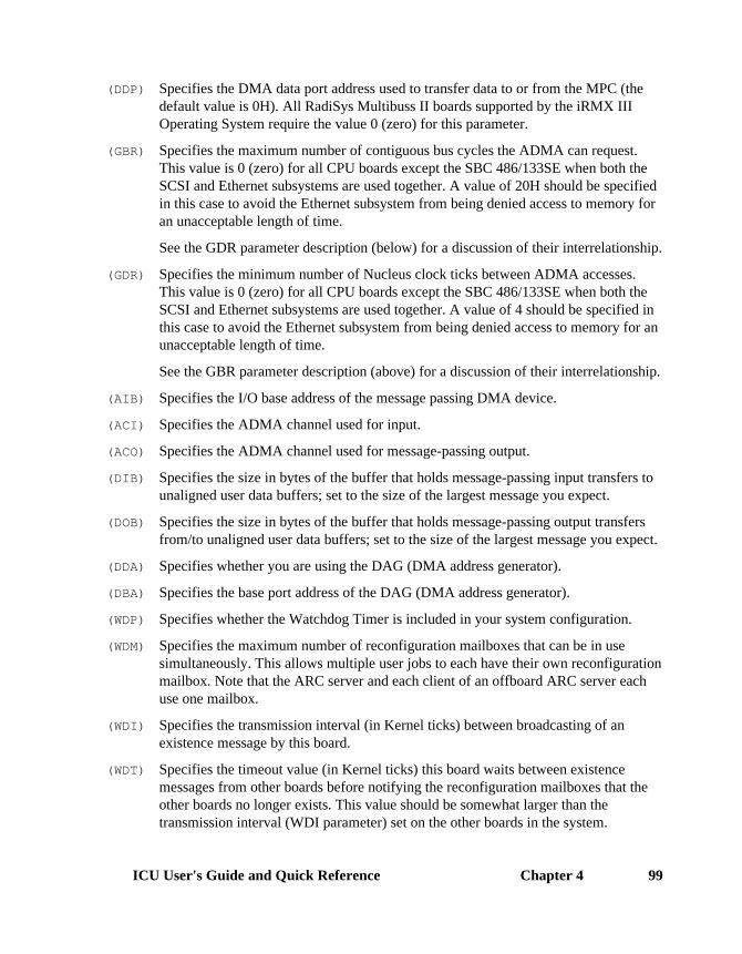
ICU User's Guide and Quick Reference Chapter 4 99
(DDP) Specifies the DMA data port address used to transfer data to or from the MPC (thedefault value is 0H). All RadiSys Multibuss II boards supported by the iRMX IIIOperating System require the value 0 (zero) for this parameter.
(GBR) Specifies the maximum number of contiguous bus cycles the ADMA can request.This value is 0 (zero) for all CPU boards except the SBC 486/133SE when both theSCSI and Ethernet subsystems are used together. A value of 20H should be specifiedin this case to avoid the Ethernet subsystem from being denied access to memory foran unacceptable length of time.
See the GDR parameter description (below) for a discussion of their interrelationship.
(GDR) Specifies the minimum number of Nucleus clock ticks between ADMA accesses.This value is 0 (zero) for all CPU boards except the SBC 486/133SE when both theSCSI and Ethernet subsystems are used together. A value of 4 should be specified inthis case to avoid the Ethernet subsystem from being denied access to memory for anunacceptable length of time.
See the GBR parameter description (above) for a discussion of their interrelationship.
(AIB) Specifies the I/O base address of the message passing DMA device.
(ACI) Specifies the ADMA channel used for input.
(ACO) Specifies the ADMA channel used for message-passing output.
(DIB) Specifies the size in bytes of the buffer that holds message-passing input transfers tounaligned user data buffers; set to the size of the largest message you expect.
(DOB) Specifies the size in bytes of the buffer that holds message-passing output transfersfrom/to unaligned user data buffers; set to the size of the largest message you expect.
(DDA) Specifies whether you are using the DAG (DMA address generator).
(DBA) Specifies the base port address of the DAG (DMA address generator).
(WDP) Specifies whether the Watchdog Timer is included in your system configuration.
(WDM) Specifies the maximum number of reconfiguration mailboxes that can be in usesimultaneously. This allows multiple user jobs to each have their own reconfigurationmailbox. Note that the ARC server and each client of an offboard ARC server eachuse one mailbox.
(WDI) Specifies the transmission interval (in Kernel ticks) between broadcasting of anexistence message by this board.
(WDT) Specifies the timeout value (in Kernel ticks) this board waits between existencemessages from other boards before notifying the reconfiguration mailboxes that theother boards no longer exists. This value should be somewhat larger than thetransmission interval (WDI parameter) set on the other boards in the system.

Chapter 4 ICU Quick Reference100
(NTM) Specifies the number of trace messages permitted for debugging purposes on thisboard. Each trace message requires 32 bytes of memory, which is taken from theroot job.
For each trace message specified here, the system allocates 32 bytes for an inputbuffer and 32 bytes for an output buffer. Therefore, each trace message specified hererequires 64 bytes of the root job’s memory.
Trace messages are used by the System Debugger’s VMF, VMI, and VMOcommands. To use these commands you must specify at least one trace message.

ICU User's Guide and Quick Reference Chapter 4 101
OS Extension ScreenThis is a repetitive screen. Do not enter names or numbers you have already used onanother OS Extension screen.
See also: OS Extensions, System Concepts
(OSEXT) O.S. Extension
(GSN) GDT Slot Number [440-8189]
(EPN) Entry Point Name [1-45 Chars]
(GSN) Specifies in decimal the actual GDT slot to reserve for a call gate.
(EPN) Specifies the PUBLIC name of the entry procedure that the call gate enters the OSextension from.
Query ScreenThe Query screen appears after you complete the Device Driver screens, the UnitInformation screens, the Device-Unit Information screens, the I/O Jobs screen, theAFAU screen, the OSEXT screen, and the User Jobs screen.
Do you need any/more [screen name] ?
Respond Yes if you need more screens; otherwise, respond No or <CR>.

Chapter 4 ICU Quick Reference102
ROM Code ScreenUse this screen to place your system in (EP)ROM; otherwise respond No to the firstparameter.
See also: Developing applications for ROM, Programming Techniques andAEDIT Text Editor
(ROM) ROM Code
(SYR) System in ROM [Yes/No]
(CPI) Copy ROM Initialization Code to RAM [Yes/No]
(EOR) Execute System Out of ROM/Flash [Yes/No]
(VSS) Volatile System Memory Starting Address [0-0FFFFFFFFH]
(VSE) Volatile System Memory Ending Address [0-0FFFFFFFFH]
(RBA) Base Address of ROM Init code at reset [0-0FFFFFFFFH]
(RDA) RAM Destination Address of ROM Init code [0-0FFFFFFFFH]
(SRC) Size of ROM Initialization Code [0-0FFFFFFFFH]
(CRS) Custom ROM Initialization Source File [1-45 Chars]
(CRO) Custom ROM Initialization Object File [1-45 Chars]
(SYR) Specifies whether the application will reside in ROM.
(CPI) Specifies whether ROM initialization code is copied to RAM.
(EOR) Specifies whether to execute the first-level jobs out of ROM or FLASH.
(VSS), (VSE)Specifies the first and last addresses for volatile memory not dedicated to anyhardware function.
(RBA) Specifies the 32-bit physical base address of the ROM Initialization Code at systemreset.
(RDA) Specifies the 32-bit physical address in RAM where the ROM Initialization Code iscopied if the CPI parameter is YES.
(SRC) Specifies the size of the ROM Initialization Code.
(CRS) Specifies a source file with customized ROM Initialization Code.
(CRO) Specifies the object code containing external procedures used by your custom ROMInitialization Code.

ICU User's Guide and Quick Reference Chapter 4 103
Shared C Library Screen(CLIB) Shared C Library
(NEB) Number of EIOS buffers per connection [0-225]
(MBS) Malloc block size [16-0FFFFFFFFH]
(NL) Numeric Library [Yes/No]
(SKL) Sockets Library [Yes/No]
(CIO) Console I/O [EIOS/SDM/User/None]
(UCP) User Console I/O Procedure [1-45 Chars]
(NEB) Specifies how many buffers to allocate per connection.
(MBS) Specifies the size in bytes of the memory block to allocate for each malloc call.
(NL) Specifies whether to include the library that provides floating-point functions.
(SKL) Specifies whether to include the optional library that provides a socket interface tothe TCP/IP stack.
(CIO) Specifies which sub-system provides I/O for stdin and stdout.
(UCP) Specifies the pathname of the object module containing the PUBLIC names for :ci:and :co:, if you selected other than None for (CIO).

Chapter 4 ICU Quick Reference104
Subsystems ScreenThe Nucleus is always included; the subsystems are optional. Each optionalsubsystem requires the Nucleus and may require at least one other subsystem; theICU adds the required subsystems as shown below.
See also: Using segments and subsystems, Programming Techniques and AEDITText Editor
Supporting SubsystemsSubsystem HI AL EIO BIO SDM SDBUDI Req Req Req ReqHI Req Req ReqAL Req* ReqiRMX-NET ReqEIOS ReqBIOSSDB ReqSDMCLIB (for full functionality) Req Req Req Req Req
* See also ASC on the APPL screen
Adding a subsystem increases both capabilities and memory requirements. Thememory requirements for each of the subsystems are
Sub-system Approximate Memory RequiredNucleus 105KBIOS 95K*EIOS 19KAL 12KHI 36KCLI 56K (Release 2 CLI)UDI 11KSDB 57KCLIB (for full functionality) 85K
* This is the BIOS size in the Intel-supplied start-up system. The BIOS variesdepending on how many file and device drivers you included in the system.
See also: Individual subsystems, Introducing the iRMX Operating Systems

ICU User's Guide and Quick Reference Chapter 4 105
(SUB) Sub-systems
(UDI) Universal Development Interface [Yes/No]
(CLB) Shared C Library [Yes/No]
(HI) Human Interface [Yes/No]
(AL) Application Loader [Yes/No]
(NET) Networking [Yes/No]
(EIO) Extended I/O System [Yes/No]
(BIO) Basic I/O System [Yes/No]
(PGS) Paging Subsystem [Yes/No]
(NTS) Windows NT Subsystem [Yes/No]
(VMD) VM86 Dispatcher [Yes/No]
(SDM) System Debug Monitor [Yes/No]
(SDB) System Debugger [Yes/No]
(OE) OS Extension [Yes/No]
(UDI) Provides a standard set of system calls that enables applications to run on any OSsupporting the UDI.
(CLB) Provides ANSI-compatible C functions as a single, multitasking subsystem.
(HI) Provides an interactive interface between users and applications.
(AL) Loads object files into memory from secondary storage: absolute code into fixedlocations, relocatable code into dynamically allocated memory locations, and filescontaining overlays.
(NET) Specifies whether you want to include any of the networking systems, includingiNA 960, iRMX-NET, TCP/IP, or X.25.
(EIO) Provides high-level, synchronous file access and device independence forapplications.
(BIO) Provides asynchronous file access and device independence for applications.
(PGS) Specifies whether or not the Paging Subsystem is included to support your flat-modelapplications.
(NTS) Determines whether the Windows NT Subsystem is included in your applicationsystem. Including this subsystem (by selecting Yes) produces the generation filesnecessary to build an INtime syste. Without these files, generation of this system willfail because the generation libraries needed to produce an INtime system are not partof iRMX III.2.3.
(VMD) (iRMX for PCs and DOSRMX) Enables DOS and ROM/BIOS software to run inVM86 mode.
(SDM) Provides the SDM monitor to help debug applications.

Chapter 4 ICU Quick Reference106
(SDB) Extends the use of SDM so that you can interactively examine data structures.
See also: System Debugger Reference
(OE) Enables you to modify the OS to add OS extensions.
See also: OS extensions, System Concepts

ICU User's Guide and Quick Reference Chapter 4 107
System Debugger Screens
System Debugger Screen(SDB) System Debugger
(SLV) SDB Interrupt Level [Encoded Level/NONE=0FFH]
(ESC) Enable Screen Scrolling [Yes/No]
(SLV) Specifies the encoded interrupt level, if any, that your system uses to invoke the SDB.
(ESC) Specifies whether or not to enable screen display scroll control.
System Debug Console Screen for Multibus I/II(SDM) System Debug Console
Multibus Drivers
(D51) 8251 Console Controller Driver [Primary/Secondary/No]
(A54) 354 Port A Console Controller Driver [Primary/Secondary/No]
(B54) 354 Port B Console Controller Driver [Primary/Secondary/No]
(A74) 8274 Port A Console Controller Driver [Primary/Secondary/No]
(B74) 8274 Port B Console Controller Driver [Primary/Secondary/No]
(G79) SBX 279 Console Controller Driver [Primary/Secondary/No]
(A30) 82530 Port A Console Controller Driver [Primary/Secondary/No]
(B30) 82530 Port B Console Controller Driver [Primary/Secondary/No]
(RCI) Remote Console Interface Driver [Primary/Secondary/No]
PC Drivers
(SR1) Serial Port One [Primary/Secondary/No]
(BP1) Serial Port One Base Address [0-0FFFFH]
(SR2) Serial Port Two [Primary/Secondary/No]
(BP2) Serial Port Two Base Address [0-0FFFFH]
(CON) Console Port [Primary/Secondary/No]
(D51), (A54), (B54), (A74), (B74), (G79), (A30), (B30), (RCI)Specifies which I/O device SDM uses. Choose at least one primary channel andoptionally one secondary channel.
(SR1), (SR2), (CON)Specifies which I/O device SDM uses on a PC. Choose at least one primary channeland optionally one secondary channel.

Chapter 4 ICU Quick Reference108
(BP1), (BP2)Specifies the base IO Address of Serial Ports One and Two (COM1 and COM2).
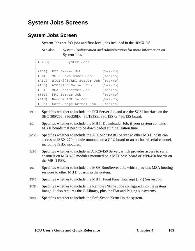
ICU User's Guide and Quick Reference Chapter 4 109
System Jobs Screens
System Jobs ScreenSystem Jobs are I/O jobs and first-level jobs included in the iRMX OS.
See also: System Configuration and Administration for more information onSystem Jobs
(SYSJ) System Jobs
(PCI) PCI Server Job [Yes/No]
(DL) MBII Downloader Job [Yes/No]
(ATC) ATCS/279/ARC Server Job [Yes/No]
(A50) ATCS/450 Server Job [Yes/No]
(BS) MSA BootServer Job [Yes/No]
(FPI) FPI Server Job [Yes/No]
(RIN) Remote INtime Job [Yes/No]
(SSK) Soft-Scope Kernel Job [Yes/No]
(PCI) Specifies whether to include the PCI Server Job and use the SCSI interface on theSBC 386/258, 386/258D, 486/133SE, 386/12S or 486/12S board.
(DL) Specifies whether to include the MB II Downloader Job, if your system containsMB II boards that need to be downloaded at initialization time.
(ATC) Specifies whether to include the ATCS/279/ARC Server so other MB II hosts canaccess an iSBX 279 module mounted on a CPU board or an on-board serial channel,including iSBX modules.
(A50) Specifies whether to include an ATCS/450 Server, which provides access to serialchannels on MIX/450 modules mounted on a MIX base board or MPI/450 boards onthe MB II PSB.
(BS) Specifies whether to include the MSA BootServer Job, which provides MSA bootingservices to other MB II boards in the system.
(FPI) Specifies whether to include the MB II Front Panel Interrupt (FPI) Server Job.
(RIN) Specifies whether to include the Remote INtime Jobe configured into the systemimage. It also requires the C-Library, plus the Flat and Paging subsystems.
(SSK) Specifies whether to include the Soft-Scope Kernel in the system.

Chapter 4 ICU Quick Reference110
PCI Server Job Screen(PCIJ) PCI Server Job
(ODS) Object Directory Size [0-3840]
(PMI) Pool Minimum [60H-0FFFFFFFH]
(PMA) Pool Maximum [60H-0FFFFFFFH]
(MOB) Maximum Objects [1-0FFFFH]
(MTK) Maximum Tasks [1-0FFFFH]
(MPR) Maximum Priority [0-255]
(PV) Parameter Validation [Yes/No]
(TP) Task Priority [0-255]
(SSI) Stack Size [0-0FFFFH]
(MI) Multibus I SPC RMX Level [0-0FFH]
(AC) SCSI Auto Configuration [Yes/No]
(NS) Number of PCI Server SCSI controllers [1-10]
(ODS) Specifies in decimal the maximum number of entries in this job's object directory.
(PMI), (PMA)Specifies in 16-byte paragraphs the minimum and maximum sizes of this job'smemory pool.
(MOB) Specifies how many objects can exist simultaneously in this job.
(MTK) Specifies how many tasks can exist simultaneously in this job.
(MPR) Specifies in decimal the highest priority of tasks in this job.
(PV) Specifies whether to include parameter validation for Nucleus system calls made bytasks in this job, if you included system-level parameter validation.
(TP) Specifies the priority of this job's initialization task.
(SSI) Specifies in bytes the size of the initialization task's stack segment, according to yoursegmentation model.
(MI) Specifies the RMX interrupt level for the SCSI Protocol Chip as defined jumper.
(AC) Specifies whether a custom or default PCI Server is required to control the SCSI chipon a Multibus board.
(NS) Specifies the number of SCSI controllers or devices being supported.

ICU User's Guide and Quick Reference Chapter 4 111
PCI Server Controller Configuration Screen(PCISC) PCI Server Controller Configuration
(SCT) SCSI Controller Type [0-0FFH]
(BA) Base Address [0-0FFFFH]
(STO) Select Timeout [0-0FFH]
(BON) Bus On Time [0-0FFH]
(BOF) Bus Off Time [0-0FFH]
(XS) Xfer Speed [0-0FFH]
(L0O) Scan Lun 0 Only [Yes/No]
(INT) RMX Interrupt Level [0-0FFH]
(SI) SCSI Id [0-7]
(RES) Reset SCSI Bus [Yes/No]
(DMA) DMA Channel [5-7]
(NC) Number of CCBs [1-8]
(SCT) Specifies the SCSI controller device.
(BA) Specifies the base address of the SCSI controller.
(STO) Specifies how long the SCSI controller will wait before timing out on a select.
(BON), (BOF)Specifies in microseconds the burst-on and burst-off times during DMA transfersacross the bus.
(XS) Specifies the SCSI controller’s maximum transfer rate during data transfers.
(L0O) Specifies whether the PCI Server scans all logical devices or just logical device 0during the SCSI bus scan.
(INT) Specifies the iRMX encoded value used by the SCSI controller for the interrupt level.
(SI) Specifies the SCSI identification for the device.
(RES) Specifies whether the SCSI bus will reset at initialization.
(DMA) Specifies the DMA channel used by the SCSI controller.
(NC) Allocates space to interface with the Adaptec controller.
✏ NoteFor more specific details, see the ICU help messages for this screenand for each parameter.
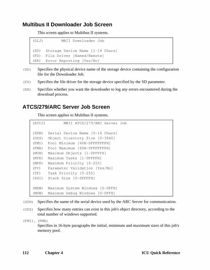
Chapter 4 ICU Quick Reference112
Multibus II Downloader Job ScreenThis screen applies to Multibus II systems.
(DLJ) MBII Downloader Job
(SD) Storage Device Name [1-14 Chars]
(FD) File Driver [Named/Remote]
(ER) Error Reporting [Yes/No]
(SD) Specifies the physical device name of the storage device containing the configurationfile for the Downloader Job.
(FD) Specifies the file driver for the storage device specified by the SD parameter.
(ER) Specifies whether you want the downloader to log any errors encountered during thedownload process.
ATCS/279/ARC Server Job ScreenThis screen applies to Multibus II systems.
(ATCJ) MBII ATCS/279/ARC Server Job
(SDN) Serial Device Name [0-14 Chars]
(ODS) Object Directory Size [0-3840]
(PMI) Pool Minimum [60H-0FFFFFFFH]
(PMA) Pool Maximum [60H-0FFFFFFFH]
(MOB) Maximum Objects [1-0FFFFH]
(MTK) Maximum Tasks [1-0FFFFH]
(MPR) Maximum Priority [0-255]
(PV) Parameter Validation [Yes/No]
(TP) Task Priority [0-255]
(SSI) Stack Size [0-0FFFFH]
(MSW) Maximum System Windows [0-0FFH]
(MDW) Maximum Debug Windows [0-0FFH]
(SDN) Specifies the name of the serial device used by the ARC Server for communication.
(ODS) Specifies how many entries can exist in this job's object directory, according to thetotal number of windows supported.
(PMI), (PMA)Specifies in 16-byte paragraphs the initial, minimum and maximum sizes of this job'smemory pool.

ICU User's Guide and Quick Reference Chapter 4 113
(MOB) Specifies how many objects can exist simultaneously in the job.
(MTK) Specifies how many tasks can exist simultaneously in this job.
(MPR) Specifies in decimal the highest priority of tasks in this job.
(PV) Specifies whether to include parameter validation for Nucleus system calls made bytasks in this job, if you included system-level parameter validation.
(TP) Specifies in decimal the priority of this job's initialization task.
(SSI) Specifies in bytes the size of the initialization task's stack segment, according to yoursegmentation model.
(MSW) Specifies how many windows the 279 portion of the ATCS/279/ARC Server Jobs canprovide to other hosts in the MB II system.
(MDW) Specifies how many windows the 279 portion of the ATCS/279/ARC Server canprovide for debug monitors running on other MB II processors in the system.
ATCS/450 Server Job ScreenThis screen applies to Multibus II systems.
(ATC50) MBII ATCS/450 Server Job
(ODS) Object Directory Size [0-3840]
(PMI) Pool Minimum [60H-0FFFFFFFH]
(PMA) Pool Maximum [60H-0FFFFFFFH]
(MOB) Maximum Objects [1-0FFFFH]
(MTK) Maximum Tasks [1-0FFFFH]
(MPR) Maximum Priority [0-255]
(PV) Parameter Validation [Yes/No]
(TP) Task Priority [0-255]
(SSI) Stack Size [0-0FFFFH]
(TPA) 8254 Timer Port [0-0FFFFH]
(CIL) Clock Interrupt Level [Encoded Level]
(CN) Timer Counter Number [0,1,2]
(CF) Clock Frequency [0-65535 khz]
(TPS) Timer Port Separation [0-0FFH]
(ODS) Specifies in decimal how many entries can exist in this job's object directory.
(PMI), (PMA)Specifies in 16-byte paragraphs the initial, minimum and maximum sizes of this job'smemory pool, according to the total number of windows supported.

Chapter 4 ICU Quick Reference114
(MOB) Specifies how many objects can exist simultaneously in this job.
(MTK) Specifies how many tasks can exist simultaneously in this job.
(MPR) Specifies in decimal the highest priority of tasks in this job.
(PV) Specifies whether to include parameter validation for Nucleus system calls made bytasks in this job, if you included system-level parameter validation.
(TP) Specifies in decimal the priority of this job's initialization task.
(SSI) Specifies in bytes the size of the initialization task's stack segment, according to yoursegmentation model.
(TPA) Specifies the base port (lowest valued) address of the 8254 PIT used by theATCS/450 Server.
(CIL) Specifies the encoded interrupt level of the timer use by the ATCS/450 Server.
(CN) Specifies the number of the 8254 PIT used by the ATCS/450 Server.
(CF) Specifies the frequency in kilohertz of the clock input to the timer used by theATCS/450 Server.
(TPS) Specifies the timer port separation of the 8254 PIT used by the ATCS/450 Server.
MSA BootServer Job ScreenThis screen applies to Multibus II systems.
(BSJ) MSA BootServer Job
(IJD) I/O Job Default Prefix [1-12 Chars]
(DU) Default User [1-12 Chars]
(PMI) Pool Minimum [60-0FFFFFFFH]
(PMA) Pool Maximum [1000H-0FFFFFFFH]
(PV) Parameter Validation [Yes/No]
(TP) Task Priority [0-255]
(IJD) Specifies the logical name for the default prefix for the Bootserver Job.
(DU) Specifies the default user object for the Bootserver Job.
(PMI), (PMA)Specifies in 16-byte paragraphs the initial, minimum and maximum sizes of this job'smemory pool.
(PV) Specifies whether to include parameter validation for Nucleus system calls made bytasks in this job, if you included system-level parameter validation.
(TP) Specifies in decimal the priority of the Bootserver task.

ICU User's Guide and Quick Reference Chapter 4 115
FPI Server Job ScreenThis screen applies to Multibus II systems.
(FPIJ) FPI Server Job
(STP) Server Task Priority [0-255]
(ODS) Object Directory Size [0-3840]
(PMI) Pool Minimum [60H-0FFFFFFFH]
(PMA) Pool Maximum [60H-0FFFFFFFH]
(MOB) Maximum Objects [1-0FFFFH]
(MTK) Maximum Tasks [1-0FFFFH]
(MPR) Maximum Priority [0-255]
(PV) Parameter Validation [Yes/No]
(SSI) Stack Size [0-0FFFFH]
(FIL) Front Panel Interrupt Level [Encoded Level]
(STP) Specifies in decimal the Front Panel Interrupt Server's message task priority.
(ODS) Specifies in decimal the maximum number of entries in this job's object directory.
(PMI), (PMA)Specifies in 16-byte paragraphs the initial, minimum and maximum size of the FPIJob's memory pool.
(MOB) Specifies how many objects can exist simultaneously in this job.
(MTK) Specifies how many tasks can exist simultaneously in this job.
(MPR) Specifies in decimal the highest priority of tasks in this job.
(PV) Specifies whether to include parameter validation for Nucleus system calls made bytasks in this job, if you included system-level parameter validation.
(SSI) Specifies in bytes the size of the initialization task's stack segment, according to yoursegmentation model.
(FIL) Specifies the encoded hardware interrupt level for the FPI.

Chapter 4 ICU Quick Reference116
Soft-Scope Kernel Job Screen(SSKJ) Soft-Scope Kernel Job
(SCP) Communication Method [Local/Remote]
(CMM) Specifies the communication method used to interface to the kernel.

ICU User's Guide and Quick Reference Chapter 4 117
User Jobs Screens
User Jobs ScreenEach User Jobs screen represents a different user job. The Nucleus can create up to32 user jobs. User jobs are created after all other first-level jobs and all I/O jobs, butbefore the HI and any of its jobs. The order in which you define your user jobs is theorder in which the root task initializes them.
If you do not configure the HI, define at least one user job or one I/O job to becreated during initialization.
The parameters on this screen are the same as those in the create_job system call.
(USERJ) User Jobs
(NAM) Job Name [0-14 Chars]
(SEQ) Job Sequence [Before/After]
(ODS) Object Directory Size [0-3840]
(PMI) Pool Minimum [20H-0FFFFFFFH]
(PMA) Pool Maximum [20H-0FFFFFFFH]
(MOB) Maximum Objects [1-0FFFFH]
(MTK) Maximum Tasks [1-0FFFFH]
(MPR) Maximum Priority [0-255]
(EHS) Exception Handler Entry Point [1-31 Chars]
(EM) Exception Mode [Never/Prog/Environ/All]
(PV) Parameter Validation [Yes/No]
(TP) Task Priority [0-255]
(TSA) Task Entry Point [1-31 Chars]
(VAR) Public Variable Name [0-31 Chars]
(SSA) Stack Segment Address [SS:SP]
(SSI) Stack Size [0-0FFFFH]
(NPX) Numeric Processor Ext. Used [Yes/No]
(NAM) Specifies a name that will identify a particular user job screen.
(SEQ) Specifies the whether this user job must start before or after EIOS initialization.
(ODS) Specifies how many entries can exist in this user job's object directory.
(PMI), (PMA)Specifies in 16-byte paragraphs the minimum and maximum size of the user job'smemory pool.

Chapter 4 ICU Quick Reference118
(MOB) Specifies how many objects can exist simultaneously in this user job.
(MTK) Specifies how many tasks can exist simultaneously in this user job.
(MPR) Specifies in decimal the highest priority of tasks in this user job.
(EHS) Specifies the PUBLIC name of an exception handler procedure, other than the defaultsystem exception handler specified for the Nucleus.
(EM) Specifies the exception mode of the exception handler for this user job.
(PV) Specifies whether the Nucleus performs parameter validation for all Nucleus systemcalls made in this user job.
(TP) Specifies in decimal the priority of this job's initialization task.
(TSA) Specifies the PUBLIC name of the user job's entry procedure.
(VAR) Specifies the PUBLIC name of any of the user job's public variables.
(SSA) Specifies the address of the initialization task's stack.
(SSI) Specifies in bytes the size of the initialization task's stack segment; set according toyour segmentation model.
(NPX) Specifies whether the I/O job's initial task contains floating-point instructions.
User Modules ScreenUse this screen to specify the user modules included by the builder in the applicationsystem.
(USERM) User Modules
Module = 1-55 characters
[ 1] Module =
ModuleSpecifies the pathname for the object code that has been bound for the applicationjobs defined on the IOJOB screen, the USERJ screen or for the OS extensionsdefined on the OSEXT screen.
The order of the user module pathnames is not significant.
■■ ■■ ■■

ICU User's Guide and Quick Reference Appendix A 119
Error Messages AThis appendix contains descriptions of all ICU-generated error and warningmessages. There are five categories of messages:
• Invocation messages
• Interactive errors and warnings
• ICU internal errors
• System generation errors and warnings
• iRMX OS internal errors
Invocation messages appear instead of the menu when errors occur while starting theICU.
Interactive error messages indicate conditions that are not allowed by the ICU. Theseerrors occur during the ICU session, in command or screen-editing modes. All errormessages are preceded by the characters *** ERROR.
Interactive warning messages indicate conditions that are allowed during the ICUsession, but may cause problems later. All warning messages are preceded by thecharacters *** WARNING.
ICU internal errors usually occur if the screen master or template files are corrupt.
System generation errors and warnings occur during the execution of the generationsubmit file. These can be compiler, binder, or builder errors and warnings.
While running the ICU, if you encounter any error messages not shown in thisappendix, you are probably experiencing iRMX OS internal error conditions. Theseare indicated by a 4-digit condition code followed by a short error message such as:
0026: E_FILE_ACCESS
See also: Condition code master list, System Call Reference

120 Appendix A Error Messages
Invocation MessagesIf the ICU does not present the main menu, various messages can appear. If youinvoke the ICU with incorrect command syntax, this message appears:
*** INVALID INVOCATION ***
USAGE: ICU386 [input-file TO] output-file
This means you tried to invoke the ICU without an input definition file or withinvalid filename(s):
*** ERROR - FILE: <file_name> IS NOT VALID
This means you tried to invoke the ICU with a corrupted definition file, or a file thatis not a definition file.
Version Control MessagesOn invocation the ICU validates file version numbers for icu386.scm, icu386.tpl, andeach definition file. Each of these files has Intel, Update, and User version numbers.The Intel version number changes whenever Intel upgrades the ICU to support newreleases. The Update version number changes when an OS update modifies the ICU.The User version number changes whenever you add a device driver using the UDSand ICUMRG utilities.
This means there is an inconsistency in the version numbers of either icu386.scm oricu386.tpl:
***ERROR-INCONSISTENCY IN THE VERSION OF THE INTERNAL ICU FILES
Versions: Intel Update User
ICU386.SCM <Intel> + <Update> <User version>
ICU386.TPL <Intel> + <Update> <User version>
This means there is an inconsistency in the definition file:
*** WARNING - DEFINITION FILE VERSION IS NOT CORRECT.
Intel Update User
ITS VERSION IS: <the inconsistency>
VERSION EXPECTED: <correct version>

ICU User's Guide and Quick Reference Appendix A 121
Automatic Restore and Update MessagesIf the ICU needs to restore from the file in order to use it, you will be prompted:
Do you want to restore from the file? y/[n]
If you answer No, the ICU stops executing. If you answer Yes, the ICU will start arestore process.
See also: Restoring a definition file, in this manual
If the definition file version number is higher than the ICU version number, you areprobably using the wrong version of the ICU. In this case, the ICU displays thiswarning before the restore prompt:
*** WARNING - The Definition File version is NEWER
If the ICU is able to use the file without restoring, it prompts with this message:
Do you want to update the file? y/[n]
If you answer No, the ICU stops executing. If you answer Yes, the ICU will updatethe file. This is a simple process that requires no further input.

122 Appendix A Error Messages
Interactive Error and Warning MessagesThese are the possible interactive error and warning messages. Some of themessages have descriptions; the others are self-explanatory when viewed in contextwith the error condition. Values inside of < > are variables filled in by the ICU.
Interactive Error MessagesA filename is expected
You entered something other than a valid filename.
A prefix of a legal string expected
Address expectedYou entered something other than a valid address.
Allowed only in MBII systemsThe screen specified is not allowed unless the BUS parameter indicates MB IIarchitecture.
BACKUP FILE <filename> IS NOT VALIDA restore was attempted from an invalid backup file or a file that is not an ICUbackup file.
Cannot insert new instance; limit has been reachedYou have exceeded the maximum allowable number of entries in a repetitive screen.
Data of the screen <abbreviation> was not restored.This message appears in the restore log file.
Device name: <abbreviation>, is not unique.The device abbreviation you specified already exists in a driver screen.
Erroneous delimiterYou used an invalid delimiter in a repetitive screen entry (other than a comma).
Illegal field name: <abbreviation>The parameter abbreviation is invalid; it is not defined in the screen master file.
Illegal input, number expectedYou entered something other than a valid number.
Illegal interrupt levelYou entered an interrupt level that is not supported by your hardware or you specifiedan encoded interrupt level (as a system call would expect).
Illegal line numberIn a repetitive screen, you specified a line number that is out of range.

ICU User's Guide and Quick Reference Appendix A 123
In screen: <abbreviation>, DINFO : <device>, is missing.
In screen: <abbreviation>, two DINFOs have the same name.
In screen: <abbreviation>, two UINFOs have the same name.
Invalid Bits per Pixel, BPP Reset to Default Value.The graphics display hardware does not support the value specified.
Invalid Command. To Delete enter: <abbreviation>You entered a line number with the delete command on a repetitive-fixed screen.
Invalid Command. To Delete enter: <number>You did not enter a line number with the delete command on a repetitive screen.
Invalid inputYou entered a command or value at the screen prompt that does not apply to thisscreen.
Invalid input_or: Invalid Command. To Insert enter: number= valuesYou tried to use the insert command on a repetitive screen without specifying anyparameters.
iRMX-NET also configured into the system.
Line number expected.
Memory areas for SYS and FSM overlap.You specified values that cause system and free space memory spaces to overlap.
Min memory greater than max memory. Is it OK ?A starting address is higher than an ending address.
Missing quote.
No user modules defined for I/O jobs.
No user modules defined for User jobs.
Number expected or number too large.
Number is not within its range.
Offset in address is not a number.
One and Only One Primary Must Be Specified. Enter <CR> to Continue.
OS Extension slot number is bigger than number of slots.You specified a GDT slot for an OS extension that is outside the allowable limits.

124 Appendix A Error Messages
OS Extension slot number is contained in the reserved area.You specified a GDT slot for an OS extension that collides with a reserved GDT slot.
(SRV) or (CON) must be YES. Abort iRMX-NET configuration?
String too long.
The control character cannot be a UDI delimiter.
The field is Req; cannot be changed.
The first number must be SMALLER than the second.
The line entered overlaps.
The selector is not within its range.
To Insert enter: line_number= new_values.
Two OS Extensions have the same slot number.
Upper limit is smaller than the lower. Is it OK?
(WV) indicates EIOS, EIOS is not configured. Is it OK ?
Yes or No expected.

ICU User's Guide and Quick Reference Appendix A 125
Interactive Warning MessagesBackground Color Exceeds Bit Depth.
The graphics display hardware does not support the color value specified.
BIOS not configured into the system.
Change GCN to T546_CC.
DEFINITION FILE USER VERSION IS NOT CORRECT.
Do not include this logical name, it is already included.
DOS Extender Sub-system not chosen.
EIOS not configured into the system.
Foreground Color Exceeds Bit Depth.The graphics display hardware does not support the color value specified.
HI needs at least 25 directory entries.
If serial drivers are configured system generation will fail.
If terminal I/O required, (BIOS) parameter (TSC) must be "Yes".
iNA MIP Driver Job also configured into the system.
IP is not supported.
iRMX-NET also configured into the system.
No AFA User (AFAU) configured with iRMXNET Server.
No user modules defined for OS Extensions.
NOGEN causes loss of NET configuration information.
NULL1 is not supported.
Problem accessing <filename> This warning does NOT affect ICU
operation.
Remote File Access was not chosen.
SDB not configured into the system.
The excluded GDT slots are out of GDT limit. Is it OK?
The screen requested cannot be displayed.
Valid only for MBII Systems.
You should change NPX parameter in HARDWARE screen.

126 Appendix A Error Messages
Internal ICU ErrorsIf during execution the ICU encounters an internal error such as the screen master fileor the template file being corrupted, it displays this message:
*** ICU Internal Error - <number[,s]>
Where:
<number[,s]>Can be either one number or two numbers separated by a comma. Thenumbers represent an internal code for the ICU and are not meaningfulfor you. Internal ICU errors rarely occur, but if you should receive thiserror message, follow these guidelines.
1. First, assume your definition file has become corrupted, and try running the ICUagain with a new definition file.
2. If Step 1 is not the solution, try running the ICU with a new screen master fileand a new template file. Original versions of these files are kept in the directory:config:default.
3. If neither of these solves the problem, contact your Intel sales office.

ICU User's Guide and Quick Reference Appendix A 127
System Generation Error and Warning MessagesNo errors should occur during the generation of your system. However, the Builder(bld386) can generate warnings or errors when you execute the generation submitfile.
See also: ASM386 Assembly Language Reference, Intel386 Family UtilitiesUser's Guide for other error descriptions.
Builder WarningsYou can expect these Builder warnings during generation. Warning 119 alwaysoccurs when you generate an DOSRMX or iRMX for PCs system. Ignore eitherwarning; they do not interfere with a successful generation.
WARNING 269: <line-number>, NEAR '<identifier>', SEGMENT SIZE REDUCED
WARNING 119: OVERLAP BETWEEN SEGMENTS OR TABLES
LOW ADDRESS: <absolute hex address>
HIGH ADDRESS: <absolute hex address>
Builder ErrorsIn addition to warning messages, the Builder can return error messages. Do notignore error messages. They indicate serious problems which prevent the successfulgeneration of your system. These errors can occur:
ERROR 117: INVALID OBJECT FILE
FILE: file name
MODULE: module name
Possible causes for this error include:
• The file is corrupt.
• Another part of the OS received errors when it generated. Check the generationlog file for this possibility.
• Your application object module specified in the error has an invalid format. Thiscondition can occur because of a translator or linker error, or by using loadableor bootloadable modules as input. Try re-translating the source files with 80386translators to create linkable input modules for bld386, relinking with bnd386 ifnecessary.

128 Appendix A Error Messages
ERROR 118: INPUT SEGMENTS EXCEED TARGET MEMORY
There is not enough system memory for the OS image, as opposed to Free Spacememory. Adjust the MEMS screen to include more memory and reduce the FreeSpace memory on the MEMF screen by the same amount. Then regenerate thesystem.
WARNING 128: SPECIFIED MODULE NOT FOUND IN INPUT FILE
FILE: file name
MODULE: module name
The specified module was on the input list but was not found in the associated file.This can occur when you define a first-level job or I/O job but do not specify anobject module on the user module (USERM) screen.
ERROR 131: REFERENCE TO UNRESOLVED EXTERNAL SYMBOL
FILE: file name
MODULE: module name
REFERRING LOCATION: location
REFERENCED LOCATION: target
Input modules do not contain a public definition identified by target, which isreferred to as an external symbol in the segment named by location. The externaldeclaration occurs in module name of file name. Check the bnd386 output of thelinker phase for unresolved symbols in your application module(s).
ERROR 137: BAD SELF RELATIVE REFERENCE
FILE: file name
MODULE: module name
REFERRING LOCATION: location
REFERENCED LOCATION: target
The specified target and location are not in the same segment. The indicated locationis in module name in file name. This error can be caused by a translator error or byusing erroneous ASM386 code.
ERROR 158: REFERENCE TO AN EMPTY SEGMENT
FILE: file name
MODULE: module name
SEGMENT: segment name
An application module contains a reference to an empty segment identified bysegment name. Ensure that the reference is correct and reinvoke bld386 withdifferent input modules if necessary.

ICU User's Guide and Quick Reference Appendix A 129
ERROR 164: INPUT HAS TWO MODULES WITH SAME NAME
FILE: file name
MODULE: module name
An application module has the same name as an internal OS module. Rename yourmodule and regenerate the system.
ERROR 192: NO SPACE FOR SEGMENT - BASE NOT SET
SEGMENT: ??_CODE
Not enough space has been allocated for system memory. The problem must becorrected. ??_CODE is the name of the segment that did not get added to the bootfilebecause of a lack of system memory. You can add up the size of each segment thatwas excluded and determine how much additional system memory to allocate andhow much Free Space Memory to allocate. Adjust the MEMS screen to includemore memory and adjust the MEMF screen downward by the same amount.
■■ ■■ ■■

130 Appendix A Error Messages

ICU User's Guide and Quick Reference Appendix B 131
Development Environment BThis appendix outlines the required development environments forICU-configurable systems. This includes recommended hardware platform andsoftware requirements.
Hardware PlatformsThis version of the ICU operates on the iRMX target system or a PC developmentsystem running DOSRMX or iRMX for PCs.
iRMX Target SystemThe iRMX target system can be a Multibus I or II system consisting of:
• CPU board and memory (e.g. SBC 486/12S)
• System chassis and cardcage
• Mass storage devices (hard disk or tape drive)
• Video display terminal
The iRMX target system has the iRMX III OS installed on it, as preconfigured foryour basic hardware. You then run the ICU to create a bootable version of theiRMX OS that includes your application jobs and device support.
PC Target SystemThe PC must have DOSRMX or iRMX for PCs installed on it. In addition, you mustinstall the PC-hosted ICU Development Environment.
To generate a Multibus system on a PC, create the new version of the OS, specifyingthe hardware parameters and networking environment of the Multibus target system.Generate the target definition files on the development system. Use yourdevelopment network or flexible diskettes to install the generated system on thetarget system. Test the target system and regenerate it on the development system ifnecessary.

132 Appendix B Development Environment
If the target system is a PC system, use the loadrmx command to boot the newsystem, then test and regenerate if necessary.
Software RequirementsTo execute the generation submit file, you must have these Intel compilers andutilities installed on your development system:
• ASM386 and ASM286
• BND386 and BND286
• BLD386
The iRMX installation process places these in their proper directories for thegeneration process to execute without problems.
Testing and Debugging ToolsFor debugging and testing, you can use the Soft-Scope Debugger, and/oriRMX System Debuggers (SDB and/or SDM) running on your target system. Forloading and debugging of the bootable object using another system, you can use theI2ICE In-Circuit Emulator.
See also: Programming Techniques and AEDIT Text Editor
■■ ■■ ■■

ICU User's Guide and Quick Reference Appendix C 133
Using the ICU to ConfigureCustom Device Drivers
For your custom driver to work in an ICU-configurable system, you must define thedevice-specific procedures as reentrant, public procedures, and compile them usingthe rom and compact controls. Assembly language routines must follow theconditions and conventions used by the compact control. In particular, theprocedures must function in the same way as high-level language procedures.
See also: ASM386 Macro Assembler User's Guide;iC-386 Compiler User's Guide;PL/M-386 Programmer's Guide
This chapter explains how to use the OS-supplied tools UDS and ICUMRG thatsupport adding your custom device drivers to the ICU. Before using these tools, youmust:
• Assemble or compile the code for each driver you have written.
• Put the resulting object modules for terminal drivers in a single library, such asterminal.lib.
• Put the resulting object modules for random/common/custom drivers in a singlemodule, such as driver.lib.
Adding Drivers with the UDS and ICUMRG UtilitiesThe two utilities are UDS (User Device Support) and ICUMRG (ICU Merge).
• UDS transforms files of screen specifications into files that are compatible withthe ICU.
• ICUMRG merges the new files into the ICU.
With these utilities, you can add screens so that configuring your driver involves justrunning the ICU and answering the appropriate questions. You can add informationabout devices, units, and device-unit screens for as many of your custom devicedrivers as you wish. Then the ICU builds the proper DUIB, DINFO, and UINFOstructures.
C

134 Appendix C Using the ICU to Configure Custom Device Drivers
Figure C-1 shows a flowchart overview of using these utilities. The next sectionsdescribe the utilities in detail.
.scm
No
Yes
Create or ModifySpecification Filefor Input to UDS
AreNew ICUScreensCorrect?
Run ICUMRG to AddNew Screens to ICU
W-2774
.scm .tplOutput of ICUMRG is New
and Files thatDescribe New Version of ICU
.tpl
.lstExamine FileGenerated by UDS
Run UDS to Produce and Filesfor User Device
Figure C-1. Adding Drivers with UDS and ICUMRG
UDS UtilityUDS lets you set up a device information screen, a unit information screen, and adevice-unit information screen for your custom driver. The steps are:
1. Set up the screens by placing information in a file that the UDS reads.
2. Choose from a set of standard screens. For example, when describing a deviceinformation screen, you can choose from three terminal support screens, tworandom access support screens, and a general screen.

ICU User's Guide and Quick Reference Appendix C 135
3. Add auxiliary lines to the device information and unit information screens. Thisallows your device-specific information to be entered during configuration.
By choosing the appropriate screens and adding the correct number of auxiliary lines,you can set up the ICU to configure almost any device driver. Depending on thenumber of auxiliary fields defined, you can provide the new auxiliary fields withdescriptive names.
After you create the input file, the utilities do these steps:
1. Using the input file you provide, the UDS creates two files that define the newscreens. These files have extensions .scm and .tpl.
2. The ICU Merge Utility can merge these new files with the ICU.
3. The UDS also produces a listing file that has a .lst extension; the list file showshow the screens will look when added the ICU.
Creating the Input File for UDS
The UDS includes two input file templates you can modify to suit your applicationneeds:
• The file templ_1.uds is an example of a basic user input file; it contains noauxiliary help fields.
• The file templ_2.uds is a complete input file and contains examples of mostauxiliary fields.
You must add each user device driver separately, because a UDS input file can addonly one driver.
Before invoking UDS, you must create an input file that defines how the ICU screensfor your driver should look. Figure C-2 shows the format of that input file. Theinformation in brackets ([ ]) is not part of the input file; it simply describes the linesof the file. The xxxx characters mean you must fill in a value. The paragraphs afterthe figure describe the individual lines of the input file.

136 Appendix C Using the ICU to Configure Custom Device Drivers
#version = xxxx [1-4 character version number]
#name = xxxx [1-25 character name]
#abbr = xxx [1-3 character abbreviation]
#driver = x [driver type value, from 1 to 7]
#device [start of device information]
#dev aux = xx [number of auxiliaries, from 0 to 20]
#d01 = 'parameter name' [1-41 character parameter name, in quotes]
d01 help information [0-1024 character help information]
[Max of 1024 chars, help msgs are required]
.
. [names and help information for other]
. [auxiliary parameters]
#end [end of device information]
#unit [start of unit information]
#unit aux = xx [number of auxiliaries, from 0 to 20]
#u01 = 'parameter name' [1-41 character parameter name, in quotes]
u01 help information [0-1024 character help information]
[Max of 1024 chars, help msgs are required]
.
. [names and help information for other]
. [auxiliary parameters]
#end [end of unit information]
#duib
#duib aux = 0
#end [end of device unit information]
Figure C-2. Syntax of UDS Input File

ICU User's Guide and Quick Reference Appendix C 137
#version Specify a new 1- to 4-character user version number used to determinewhether the definition files are current. Use consistent version numbersto keep track of the latest version of the ICU.
When you invoke the ICU using an existing definition file, the ICUchecks the version number of the definition file against the versionnumber of the master .scm and .tpl files. If they are inconsistent, theICU displays the differing version numbers and asks if you want toupdate the file. The version number that the ICU displays is built fromthe value you specify here, plus the date and time on which you run theICUMRG utility.
#name Specify a 1- to 25-character name of the new driver.
#abbr Specify the 1- to 3-character abbreviation used to form screen namesand abbreviations for all three driver screens:
Screen Abbreviation Screen NameD_<abrv> <name> DriverU_<abrv> <name> Unit InformationI_<abrv> <name> Device-unit Information
If you enter abbr ABC and name High Speed ABC, your screenabbreviations would be D ABC, U ABC, and I ABC. The screen nameswould be High Speed ABC Driver, High Speed ABC Unit Information,and High Speed ABC Device-unit Information.
#driver Specify the kind of driver this is and the kind of screens to display:
Value Driver1 Terminal Support driver with one interrupt level
2 Terminal Support driver with two interrupt levels
3 Interrupt-less MB I and MB II Full Message-basedTerminal support driver
4 Interrupt-driven Random Access Support and commondrivers
5 Multibus II Full Message-based Random Access devices
6 Reserved
7 General driver
#device Specify the start of the information that applies to the deviceinformation screen. The information continues until an #end fieldappears.

138 Appendix C Using the ICU to Configure Custom Device Drivers
#dev aux Specify the number of auxiliary parameters on the device informationscreen; range is 0 to 20. If the value is 4 or less for terminal support orrandom access devices, or 14 or less for general devices, each auxiliaryparameter is displayed on a separate line, and the parameter names youspecify in the #d fields are also displayed. If more auxiliary parametersare specified, the parameters are displayed on the device informationscreen in rows of five parameters each. Then there is no room for theparameter names, and if any are entered, the UDS ignores them.
When the ICU generates a system, it gets auxiliary parameters from thedevice information screen. The ICU places random/common deviceparameters in ?icdev.a38 files and places terminal parameters in?itdev.a38 files, immediately after the Device Information structure.The ? means the character can vary.
#d01 Each field (fixed #d01 through #d20) identifies auxiliary parametersin the device information table. If a parameter fits on a single line, the1- to 41-character 'parameter name' you specify (surrounded byquotes) will be included on the menu.
Even if your table contains too many auxiliary parameters to include aparameter name for each, you must specify the #d field for a parameterif you plan to add help information for that field. Then, you can specifythe #d field without a parameter name:
#d03 =
You can also modify the parameter names and help information for thestandard parameters that normally appear on the device informationscreen you selected. For example, if you are setting up a random accessdevice and you want to modify the parameter name and helpinformation for the DS field, you could include this information in theinput file:
#ds = 'Size of Device Local Data [0-0FFFFH]'
d01 help Specify up to 1024 characters of help information; help information isrequired. The UDS assumes that the help information ends when a #appears at the start of a subsequent line or when the maximum charactercount is reached.
#end Designates the end of the device, unit, or device-unit information.
#unit Specify the start of the information that applies to the unit informationscreen. The information continues until an #end field appears.

ICU User's Guide and Quick Reference Appendix C 139
#unit aux Specify the number of auxiliary parameters on the unit informationscreen; range is 0 to 20. If 10 or less, each auxiliary parameter isdisplayed on a separate line with the parameter names you specify.With more than 10, the parameters are displayed two to a row, with noroom for parameter names.
When the ICU generates a system, it places the auxiliary parametersfrom the unit information screen in the ?itdev.a38 or ?icdev.a38 files itcreates, immediately after the Unit Information structure. The file thatis actually altered depends on the type of device: ?icdev.a38 forcommon and random devices, ?itdev.a38 for terminal devices.
#u01 Each of fields (fixed #u01 through #u20) identifies auxiliaryparameters in the unit information screen. If each of the auxiliaryparameters fits on a single line, the 1- to 41-character parameter nameyou specify here as 'parameter name' (surrounded by quotes) willbe included on the menu to describe the auxiliary parameter.
You can also use similar fields to change the parameter names and helpinformation for any of the standard parameters of the unit informationscreen.
u01 help Specify up to 1024 characters of help information for theparameters;help information is required for all parameters. The UDSassumes that the help information ends when a # appears at the start of asubsequent line.
#duib Specify the start of the information that applies to the device-unitscreen. The device-unit information continues until a #end field isencountered.
#duib aux The UDS does not support any auxiliary parameters; set this field to:
#duib aux=0
✏ NoteAll auxiliary parameter fields (#dev_aux, #unit_aux,#duib_aux) must be WORD values. The UDS will not acceptDWORDs and will write BYTE values as WORDs.

140 Appendix C Using the ICU to Configure Custom Device Drivers
Device Information Screens
This section lists the different Device Information Screens that the UDS can generate.When adding support for your own driver, choose the screen that matches the way thedriver expects the DINFO table to look. All screens in this group can also containauxiliary parameter lines. Set up auxiliary parameter lines if none of the DeviceInformation Screens listed contain enough fields to support the needs of your driver.
The meanings of fields in these screens are the same as the fields in the DINFO table.
See also: DINFO table structure in Driver Programming Concepts
• One-Interrupt Terminal Device Information
• Two-Interrupt Terminal Device Information
• Interrupt-less Multibus I and Multibus II Full Message-based Terminal DeviceInformation
• Multibus I Random Access Device Information
• Multibus II Random Access Device Information
• General Device Information
Unit Information Screens
This section lists the Unit Information Screens that the UDS can generate. Youdefine these screens by placing information into an input file, which the UDS reads.By choosing the appropriate driver type and adding the correct number of auxiliarylines to the driver's screens, you can set up the ICU to handle the configuration ofvirtually any driver. All screens in this group can contain auxiliary parameter lines.If none of the Unit Information Screens listed contain enough fields to support yourdriver, set up auxiliary parameter lines.
The meanings of the individual fields in these screens are the same as the fields in theUINFO table.
See also: UINFO table structure, in Driver Programming Concepts
• Terminal Support Unit Information
• Random Access Support Unit Information
• General Device Unit Information

ICU User's Guide and Quick Reference Appendix C 141
Device-Unit Information Screens
This section lists the Device-Unit Information Screens that the UDS generates.When adding support for your own driver, choose the screen that matches the way thedriver expects the DUIB to look. None of the screens in this group currently allowauxiliary parameter lines.
The meanings of the individual fields in these screens are the same as the fields in theDUIB.
See also: DUIB in Driver Programming Concepts
• Terminal Support Device-Unit Information
• Random Access Device-Unit Information
• General Device-Unit Information
Invoking the UDS Utility
Once you have created an input file that specifies how the screens for your devicedriver should appear, you are ready to invoke the UDS utility. To do this, ensure thatthe directory containing the UDS program also contains the UDS database file nameduds.scm. Then invoke the utility by typing:
UDS input_file TO output_file
Where:
input_fileThe name of the file that contains the information used as input to theUDS utility.
See also: UDS input file in this section
output_fileThe name portion of the output files generated by UDS. UDS addsthree-character extensions to this name when generating its output files.The two primary output files are output-file.scm and output-file.tpl.You will use these output files as input to the ICUMRG utility. Theother output file is output-file.lst, a listing file that shows exactly howthe screens will appear when added to the ICU.
Do not name your UDS output files icu386.scm or icu386.tpl.
For example, suppose you created an input file called newdriver.txt and wanted theUDS utility to generate output files called special.scm and special.tpl. To do this,you would enter:
uds newdriver.txt to special

142 Appendix C Using the ICU to Configure Custom Device Drivers
Part of the output of the UDS utility are two files with extensions .scm and .tpl (in theexample, special.scm and special.tpl). These files contain the definitions of the ICUscreens for your driver. After running the UDS utility, you will use the ICUMRGutility to add these files to the ICU.
However, before running ICUMRG, examine the listing file (in the example,special.lst). This file shows how the Device Information screen, the Unit Informationscreen, and the Device-unit Information screen will look when added to the ICU. Ifthere is a problem with the appearance of any of these files, you can catch theproblem early and rerun UDS, instead of adding incorrect screens to the ICU.
UDS Error Messages
If you make a mistake when creating the files to use as input to UDS, the UDS utilitywill display an error message.
External File and Memory Type Errors.
The detailed message will be preceded by:
*** Error in UDS
*** Cannot Attach Input FileYou did not have the proper permission to access the file containing the UDSinstructions.
*** Not enough memory for buffersYour memory partition is not large enough to permit the UDS utility to run.
*** Cannot Attach UDS SCM FileUDS needs to access a file called uds.scm, but you do not have read access to thatfile.
*** Invalid UDS.SCM FileThe UDS file uds.scm has been corrupted.
*** Cannot Create New SCM FileUDS cannot create the output file (output_file.scm).
*** Cannot Create New TPL FileUDS cannot create the output file (output_file.tpl).
*** Cannot Create LST FileUDS cannot create the listing file (output_file.lst).
*** I/O Error in File [file-name]The specified file or directory lacks read or creation permission.
UDS Input File Errors.
The detailed message will be preceded by:

ICU User's Guide and Quick Reference Appendix C 143
*** Error in UDS Input File on line <line-number>
where <line-number> is where the error occurred in the user input file.
*** Missing User VersionThe required #version statement is missing.
*** Illegal VersionThe #version number in the input file is outside the legal range of 1 to 4 characters.
*** Missing User Device NameThe required #name field is missing.
*** Illegal Device NameThe #name identifier is 0 length or is greater than 25 characters in length.
*** Missing User Device AbbrThe required #abbr identifier is missing.
*** Illegal Device AbbrThe #abbr value in the user input file is outside the legal range of 1 to 3 characters.
*** Missing User Driver TypeThe required #driver identifier is missing.
*** Illegal Driver TypeThe #driver value is outside the legal range of 1 to 7.
*** Missing User DeviceThe required #device identifier is missing.
*** Missing Number of Device AuxiliariesThe required #dev_aux identifier is missing.
*** Missing User UnitThe required #unit identifier is missing.
*** Missing Number of Unit AuxiliariesThe #unit_aux identifier is missing.
*** Missing User DuibThe #duib identifier is missing.
*** Missing Number of DUIB auxiliariesThe required #duib_aux identifier is missing.
*** DUIB Screen Can Not Have Auxiliary FieldsThe #duib_aux value in the user input file is set to other than 0.
*** Missing Equal SignThe equal sign is missing from an identifier that requires one.
*** Line Too LongA line in the user input file is longer than the allowable 132 characters.
*** Missing Auxiliary Help MessageAn auxiliary parameter line was added without its required help message.

144 Appendix C Using the ICU to Configure Custom Device Drivers
*** Auxiliary Line Out of SequenceAuxiliary parameter lines must be listed sequentially, beginning with line 01.
*** Less Auxiliary Lines than ExpectedThe number of auxiliary lines is less than the xxx_aux value of the user input file.
*** More Auxiliary Lines than ExpectedThe number of auxiliary lines is more than the xxx_aux value of the input file.
*** Illegal InputExtra characters were entered on a line after the valid input.
*** Invalid AbbreviationThe abbreviation for an auxiliary field is outside the legal range of 1 to 3 characters.
*** Abbreviation Not FoundWhen a standard parameter line or its help message was changed, the abbreviationwas entered incorrectly.
*** Number Exceeds MaximumDev_aux or unit_aux is greater than 20.
*** Number ExpectedA nonnumeric value was entered.
*** Syntax ErrorThe opening quote on a parameter name line is missing.
*** Do Not Use # Sign in TextA parameter name contains a pound symbol (#).
*** Do Not Use ( Sign in TextA parameter name contains a left parenthesis "(".
*** Missing End of Text SignThe closing quote on a parameter name line is missing.
*** Text Line Too LongA parameter name exceeds 41 characters.

ICU User's Guide and Quick Reference Appendix C 145
*** Help Message is too LongThe Help message you entered exceeds 1024 characters in length.
*** Field Name ExpectedA blank line was detected in the device, unit, or DUIB information.
*** Unexpected eofThe user input file is incomplete.
ICUMRG UtilityAfter using UDS to generate .scm and .tpl files for your new driver, use the ICUMRGutility to combine the information in these files with the definitions of all other ICUscreens (in the icu386.scm and icu386.tpl files). Before running ICUMRG, makesure these icu386.* files reside in the same directory as the ICUMRG command.Then, invoke the ICUMRG utility:
ICUMRG input_file TO output_file
Where:
input_fileThe name (minus the extension part) of the .scm and .tpl files generatedby the UDS. For example, if the UDS utility created files calledspecial.scm and special.tpl, you would specify the name special here.
output_fileThe name (minus the extension part) of new ICU files that ICUMRGwill create. For example, if you specified the name icunew, theICUMRG utility will create files called icunew.scm and icunew.tpl.These new files will contain the complete definition of the ICU,including the screens you just defined for your new driver. By namingthe files something other than icu386, you can save the previous versionof the ICU files. For testing, you can change the name of the ICUexecutable file to match the base name of the new file (e.g., icunew).Then, when you are satisfied with the updated ICU, rename youricunew, icunew.scm, and icunew.tpl test files to their icu386counterparts so they match the standard user documentation.

146 Appendix C Using the ICU to Configure Custom Device Drivers
After adding driver support to the ICU, you can configure the drivers almost as youwould any OS-supplied drivers:
1. Invoke the ICU and go to the (UDDM) UDS Device Drivers Module screen.
2. Enter the appropriate driver type, (T)erminal or (C)ommon, and the fullpathname for the location of the object code for your device driver.
3. After entering the correct value, choose the device you want to configure.
4. Fill in the appropriate values when the ICU displays the Device Information,Unit Information, and Device-Unit Information screens.
UDS Modules Screen in the ICU
(UDDM) UDS Device Driver Modules
Module= Driver type , Object code pathname
[T/C] , [1-55 Characters]
[ 1] Module=
Specify C for common/random/custom drivers and T for terminal drivers.
Place the modules according to type, with all of your terminal modules in onemodule, and all your common/random/custom drivers in a separate module. Forexample, 1 = T, terminal.lib, and 2 = C, driver.lib.
✏ NoteBefore changing the name of any ICUMRG output files toicu386.scm and icu386.tpl, save the original files by copying themto other files (such as icu_old.scm and icu_old.tpl). AlthoughICUMRG lets you add support for new drivers, once you add thatsupport, there is no way to remove it. If you decide you don't wantthe ICU to display information about one of your drivers, or youmade a mistake when adding information about your driver, youmust revert to the original files you saved (or an intermediateversion that doesn't contain support for that driver).

ICU User's Guide and Quick Reference Appendix C 147
Adding Your Driver Without the UDS and ICUMRGIf you don't want to modify the ICU, you can add your custom device driver by doingthis:
1. Get the device numbers and device-unit numbers to use in the DUIBs for yourdevices:
a. Use the ICU to configure a system containing all the OS-supplied andICU-supported user drivers you require.
b. Use the G command to generate that system.
c. Use a text editor to examine the file ?icdev.a38 (the ? means the first lettercan vary). This file contains DUIBs for all the device-units defined in yourconfiguration.
d. Look for the %DEVICETABLES macro that appears after all thedefine_duib structures. The second and third parameters in that macrolist are the next available device-unit number and the device number,respectively. For example, suppose the %DEVICETABLES macro appears:
%DEVICETABLES(NUMDUIB,0000CH,005H,003E8H)
The next available device-unit number is 0CH and the next available devicenumber is 05H.
e. Use the next available device number and device-unit number in yourDUIBs.
2. Create these:
a. A file containing the DUIBs for all device-units you are adding. Use thedefine_duib structures, and place all the structures in the same file. TheICU will include this file when assembling the ?icdev.a38 file.
b. A file containing all the device information tables of therandom/common/custom type that you are adding. Use theradev_dev_info structures for any random access drivers you add. Later,the ICU includes this file when assembling the ?icdev.a38 file.
c. If applicable, any random access or common unit information table(s). Usethe radev_unit_info structures for any random access drivers you add.Add these tables to the file created in step 2b.
d. A file containing all the device information tables of the terminal type youare adding. Use a structure similar to theterminal_device_information structure for terminal drivers. The ICUwill include this file when assembling the ?itdev.a38 file.

148 Appendix C Using the ICU to Configure Custom Device Drivers
e. If applicable, any terminal unit information table(s). Use a structure similarto terminal_unit_information for terminal drivers. Add these tablesto the file created in step 2b.
f. External declarations for any procedures you write. The procedure namesappear in either the DUIB or the DINFO table associated with this devicedriver. Add these declarations to the file created in steps 2b and 2d.
3. Use the ICU to configure your final system. When doing so:
a. Answer yes when asked if you have any device drivers not supported by theICU.
b. As input to the Custom User Devices screen, enter the pathname of yourrandom/common/custom device driver library. This refers to the librarybuilt earlier; for example, :f1:driver.lib.
c. As input to the Custom User Devices screen, enter the pathname of yourterminal device driver library. This refers to the library built earlier; forexample, :f1:terminal.lib.
d. Enter these:
• DUIB source code pathname (the file created in step 2a).
• Device and Unit source code pathnames (the files created in steps2b through 2f).
• Number of user-defined devices.
• Number of user-defined device-units.
The ICU does the rest.
Figure C-3 contains an example of the Custom User Devices screen. The bold textrepresents user input to the ICU. In this example:
• :f1:driver.lib contains the object code for the random/common/custom drivers
• :f1:terminal.lib contains the object code for the terminal driver
• :f1:duib contains the source code for the DUIBs
• :f1:rinfo.inc contains the source code for the Device and UINFO tables alongwith the necessary external procedure declarations for therandom/common/custom drivers
• tinfo.inc contains the source code for the Device and UINFO tables and thenecessary external procedure declarations for the terminal driver

ICU User's Guide and Quick Reference Appendix C 149
The code in the driver.lib file supports 1 device with 2 units. The code in terminal.libsupports 1 device with 2 units; therefore, the (ND) Number of User Defined Devices[0-0FFH] field equals 2, and the (NDU) Number of User Defined Device-Units [0-0FFH] field equals 4.
(USERD) User Devices
(OPN) Random Access Object Code Path Name [1-45 Chars/NONE]
NONE
(TOP) Terminal Object Code Path Name [1-45 Chars/NONE]
NONE
(DPN) DUIB Source Code Path Name [1-45 Chars/NONE]
NONE
(DUP) Random Access Device and Unit Source Code Path Name
[1-4 Chars/NONE]
NONE
(TUP) Terminal Device and Unit Source Code Path Name
[1-45 Chars/NONE]
NONE
(ND) Number of User Defined Devices [0-0FFH] 0H
(NDU) Number of User Defined Device-Units [0-0FFH] 0H
Terminal Device and Unit Information Names [1-16 Chars]
(N01) NONE (N02) NONE (N03) NONE
(N04) NONE (N05) NONE (N06) NONE
(N07) NONE (N08) NONE (N09) NONE
(N10) NONE (N11) NONE (N12) NONE
(N13) NONE (N14) NONE (N15) NONE
(N16) NONE (N17) NONE (N18) NONE
: OPN = :F1:DRIVER.LIB <CR>
: TOP = :F1:TERMINAL.LIB <CR>
: DPN = :F1:DUIB.INC <CR>
: DUP = :F1:RINFO.INC <CR>
: TUP = :F1:TINFO.INC <CR>
: ND = 2 <CR>
: NDU = 4 <CR>
Figure C-3. Example User Devices Screen

150 Appendix C Using the ICU to Configure Custom Device Drivers
Example of Adding an Existing Driver as a Custom DriverThis section illustrates how to create the screens needed for adding the 544A deviceto your system using the UDS. Because device configuration is complex, theexample covers the process in detail.
While reading this example, keep in mind that the code for terminal drivers is in adifferent segment than the code for random or common drivers. Because of this splitin the segments, you must be careful to properly provide the correct publics,extrns, and nopublics except, and also to properly bind the code segmentstogether.
(USERD) User Devices
(OPN) Random Access Object Code Path Name [1-45 Chars/NONE]
NONE
(TOP) Terminal Object Code Path Name [1-45 Chars/NONE]
NONE
(DPN) Duib Source Code Path Name [1-45 Chars/NONE]
DUIB.INC
(DUP) Random Access Device and Unit Source Code Path Name
[1-45 Chars/NONE]
NONE
(TUP) Terminal Device and Unit Source Code Path Name
[1-45 Chars/NONE]
TINFO.INC
(ND) Number of User Defined Devices [0-0FFH] 01H
(NDU) Number of User Defined Device-Units [0-0FFH] 04H
Terminal Device and Unit Information Names [1-16 Chars]
(N01) DINFO_544A (N02) UINFO_544A (N03) NONE
(N04) NONE (N05) NONE (N06) NONE
(N07) NONE (N08) NONE (N09) NONE
(N10) NONE (N11) NONE (N12) NONE
(N13) NONE (N14) NONE (N15) NONE
(N16) NONE (N17) NONE (N18) NONE
The TOP option was left at NONE in this example because the 544A driver code isalready in the driver library xcmdrv.lib. If you were adding another module, youwould enter the location of the file as a full pathname.

ICU User's Guide and Quick Reference Appendix C 151
The OPN and DUP options were left at NONE because the driver being configured isa terminal driver, not a random access, common, or custom driver.
You can add combinations of up to 18 Terminal DINFO and UINFO public names inthis screen.
Contents of the Duib.inc File Specified in the (DPN) Parameter
Figure C-4 shows the contents of the file whose pathname you supplied in the (DPN)DUIB Source Code Pathname parameter of the User Devices Screen. This assembly-language file provides the information to define how the operating system shouldinterface with the device.
Note the lines with arrows pointing to them. These are the device number anddevice-unit number for this device, and the numbers were taken from the ?icdev.a38file:
1. Make sure that the files you start with contain all of the OS-supplied andICU-supported drivers you require. If you haven't generated such a system, usethe ICU to do so before continuing.
2. Use a text editor to examine the file ?icdev.a38 (the ? means that the first lettercan vary). You will find all of the DUIBs for your entire system in this file.Scan this file for a line that starts with %DEVICETABLE.
3. %DEVICETABLE is a macro that appears below all of the systems'define_duib structures. The second and third parameters in that macro are thenext available device-unit and device number, respectively. For example,suppose the %DEVICETABLE macro appears:
%DEVICETABLE (NUMDUIB, 0002EH, 008H, 003E8H)
In this case, the next available device-unit number is 2EH and the next availabledevice number is 08H.
4. Use these numbers to fill in the two lines of the file identified by the arrows.
At the end of this file are several more lines that should be noted. Be sure to examinethe last part of this figure and read the text that goes with it.

152 Appendix C Using the ICU to Configure Custom Device Drivers
DEFINE_DUIB <& 'T2',& 00001H,& 0FBH,& 00,& 00,& 00,& 00,& 08H, …< Put next available DEVICE NUMBER here& 0H,& 2EH, …< Put next available DEVICE-UNIT NUMBER here& TSINITIO,& TSFINISHIO,& TSQUEUEIO,& TSCANCELIO,& DINFO_544A,& UINFO_544A,& 0FFFFH,& 0,& 130,& FALSE,& 0H,& 0&>DEFINE_DUIB <& 'T3',& 00001H,& 0FBH,& 00,& 00,& 00,& 00,& 08H, …< The DEVICE NUMBER is the same& 0H,& 2FH, …< The DEVICE-UNIT number (T3) is equal to the& TSINITIO, DEVICE-UNIT number of 'T2' plus one.& TSFINISHIO,& TSQUEUEIO,& TSCANCELIO,& DINFO_544A,& UINFO_544A,& 0FFFFH,& 0,& 130,& FALSE,& 0H,& 0&>
Figure C-4. Computing Device and Device-Unit Numbers

ICU User's Guide and Quick Reference Appendix C 153
DEFINE_DUIB <& 'T4',& 00001H,& 0FBH,& 00,& 00,& 00,& 00,& 08H, …< The DEVICE NUMBER is the same& 0H,& 30H, …< The DEVICE-UNIT number (T4) is equal to the& TSINITIO, DEVICE-UNIT number of 'T3' plus one.& TSFINISHIO,& TSQUEUEIO,& TSCANCELIO,& DINFO_544A,& UINFO_544A,& 0FFFFH,& 0,& 130,& FALSE,& 0H,& 0&>DEFINE_DUIB <& 'T5',& 00001H,& 0FBH,& 00,& 00,& 00,& 00,& 08H, …< The DEVICE NUMBER is the same& 0H,& 31H, …< The DEVICE-UNIT number (T5) is equal to the& TSINITIO, DEVICE-UNIT number of 'T4' plus one.& TSFINISHIO,& TSQUEUEIO,& TSCANCELIO,& DINFO_544A,& UINFO_544A,& 0FFFFH,& 0,& 130,& FALSE,& 0H,& 0&>
Figure C-4. Computing Device and Device-Unit Numbers (continued)

154 Appendix C Using the ICU to Configure Custom Device Drivers
BIOS_CODE ENDS …<TSC_CODE SEGMENT ER PUBLIC
extrn DINFO_544A : far NEW PORTION OF FILE
extrn UINFO_544A : far TO ACCOUNT FOR NEW SEGMENT
TSC_CODE ENDS BIOS_CODE SEGMENT …<
Figure C-4. Computing Device and Device-Unit Numbers (continued)
The lines starting with BIOS_CODE ENDS through BIOS_CODE SEGMENT must beadded to the end of the file. They provide BND386 with information on the locationof your information tables. You must provide an extrn <MODULE_NAME>: far
declaration for each DINFO and UINFO public name specified here; these namesmust be supplied as parameters N01 through N18 above in the USERD screen. Thisdeclaration is required because all terminal information is stored in a differentphysical segment than other driver information, and a far call is required to access it.
Contents of the File Specified in the (TUP) Parameter
Figure C-5 shows the contents of the file whose pathname you supplied in the (TUP)Terminal Device and Unit Source Code Path Name parameter of the User DevicesScreen. This assembly-language file provides the information to define how theoperating system should interface with this device.

ICU User's Guide and Quick Reference Appendix C 155
extrn I544INIT : near
extrn I544FINISH : near
extrn I544SETUP : near
extrn I544CHECK : near
extrn I544ANSWER : near
extrn I544HANGUP : near
extrn I544UTILITY : near
;
PUBLIC DINFO_544A <DINFO_544A DW 04H DW 9 %DW 300 %DW I544INIT %DW I544FINISH %DW I544SETUP %DW TERMNULL %DW I544ANSWER PUBLIC
%DW I544HANGUP DECLARATIONS
%DW I544UTILITY DW 1 DW 071H %DW I544CHECK DD 0FE0000H DW 04000H DB 01H
PUBLIC UINFO_544A <UINFO_544A DW 01AH
DW 0109H
%DW 02580H
%DW 00000H
DW 012H
Figure C-5. Public Declarations Needed for the DINFO and UINFO Tables
Provide the normal extrn <MODULE_NAME>: near declarations for I544INIT, ...,I544FINISH procedures. You must also provide a PUBLIC <table name> labelbefore each DINFO and UINFO table specified.

156 Appendix C Using the ICU to Configure Custom Device Drivers
Portion of System Generation Submit File as Changed by this Process
After completing the changes outlined above, you must generate a new system usingthe ICU. During the generation process, information is sent to the screen.Figure C-6 presents those portions of system generation that are changed by theprevious steps.
; BIOS
.
ASM386 ICDEV.A38
ASM386 ITDEV.A38
.
BND386 & < SEPARATE BIND OF TSC CODE SEGMENT
ITDEV.OBJ, &
/RMX386/IOS/XDRMB1.LIB, &
/RMX386/IOS/XCMDRV.LIB(XTSIF), &
/RMX386/IOS/XCMDRV.LIB(XTSIO), &
/RMX386/IOS/XCMDRV.LIB, &
/INTEL/LIB/PLM386.LIB, &
/RMX386/LIB/RMXIFC32.LIB &
RENAMESEG(CODE32 TO TSC_CODE, TSC_CODE32 TO TSC_CODE, &
CODE TO TSC_CODE, DATA TO TSC_DATA) &
OBJECT (TSC.LNK) NODEBUG NOTYPE SEGSIZE(STACK(0)) &
NOLOAD NOPUBLICS EXCEPT( TSCINITIO, &
TSCFINISHIO, &
DINFO_02H, &
UINFO_8251, &
DINFO_03H, &
UINFO_18848, &
DINFO_04H, &
UINFO_546, &
UINFO_546CC, &
DINFO_05H, &
UINFO_547A, &
DINFO_06H, &
UINFO_547B, &
DINFO_07H, &
UINFO_547C, &
DINFO_544A, & < USER SPECIFIED
Figure C-6. Portion of the Modified Submit File

ICU User's Guide and Quick Reference Appendix C 157
BND386 &
IOS1.LNK, &
TSC.LNK, & < INCLUSION OF TSC SUBSYSTEM IN IOS
SYSTEM BIND
ICDEV.OBJ, &
/RMX386/IOS/XDRMB1.LIB, &
/RMX386/IOS/XCMDRV.LIB, &
/INTEL/LIB/PLM386.LIB, &
/RMX386/LIB/RMXIFC32.LIB &
RENAMESEG(DRV_CODE TO CODE, CODE32 TO CODE, TSC_DATA TO DATA) &
OBJECT (IOS2.LNK) NODEBUG NOTYPE SEGSIZE(STACK(0)) &
NOLOAD NOPUBLICS EXCEPT (rqaiosinittask , &
RqAttachDevice , &
.
.
.
Figure C-6. Portion of the Modified Submit File (continued)
■■ ■■ ■■

158 Appendix C Using the ICU to Configure Custom Device Drivers

ICU User’s Guide and Quick Reference Appendix D 159
Standard Definition Filesfor the iRMX III OS
This appendix describes the definition files that you receive with the OS. It includesfiles for Multibus I and II systems as well as PC systems. Use the ICU to create oredit a definition file. A definition file contains values for theICU-configurable parameters of the operating system. Create different definitions tocreate different systems.
For example, you can add or delete devices from your target system using the ICU.When you change a parameter using the ICU, save the change when you exit theICU. Use the updated file to generate a custom version of the operating system. Thisappendix lists the attributes of the systems defined by the standard definition files.
See also: ICU Operations , Chapter 2;Programming Techniques and Aedit Text Editor
✏ NoteIn the /rmx386/icu directory you can find an example definition filenamed 433sexpl.bck. This file contains definitions for DUIBs nolonger documented. These include all PCI_B devices and alldevices with SCSI ID 4 and 5 (e.g. GSCW5_4 and M4380_5). Ifyou need these DUIBs defined, you can get their definitions fromthis example file.
See also: /rmx386/update/readme.txt
D

160 Appendix D Standard Definition Files for the iRMX III OS
Standard Definition File NamesThe Standard ICU Definition Files provided for CPU boards use a namingconvention that includes the board name followed by a suffix that indicates the natureof the application created by the definition file. These are the suffixes and theirmeanings:
s Supports PCI servercp Supports PCI client and iRMXNET COMMputerscp CP configuration with PCI servernet Supports PCI client and iRMXNET COMMenginesnet NET configuration with PCI serverrsd Diskless operation (LCI client)io I/O application; PCI server, LCI server, and no Human Interface. This
is the only configuration where CLIB and SDB are not first-level jobs.msd diskless operation iRMXNET COMMputer using the Multibus II
Subnetcp2 Multibus II multiple subnet support, TCP/IPcpp Supports PCI client, iRMXNET COMMputer, and iRMX partitioning
For example, 38612net.bck definition file builds a COMMengine networkingconfiguration for the SBC 386/12 board.

ICU User’s Guide and Quick Reference Appendix D 161
Multibus I Standard Definition FilesThis section describes information about the standard definition files for Multibus Isystems.
File ApplicationsMost boards are supported with several definition files: one for local applications,one or two for networking applications, and one for diskless networking applications.This list describes the different types of applications:
Local Configurations of the operating system that use only theresources in the chassis containing the CPU board. A localhard disk for the system device :sd: is required. Thesedefinition filenames map to the name of the CPU board, forexample, 38612.bck.
COMMengine Networking configurations of the operating system that use aCPU board and a separate Ethernet controller board. The OSaccesses resources both inside and outside the chassis thatcontains the CPU board. The iRMX-NET software isconfigured to be both a file server and client to provide accessto the Local Area Network (LAN). A local hard disk for thesystem device :sd: is required. The definition files forCOMMengine networking applications consist of the name ofthe CPU board with net appended.
COMMputer Networking configurations of the operating system that use aCPU board that includes an Ethernet controller. These boardsrequire an SBX 586 module for the Ethernet controller. TheOS accesses resources both inside and outside the chassis thatcontains the CPU board. TheiRMX-NET software is configured to be both a file server andclient to provide access to the LAN. The SBX 586 module iscontrolled by the iRMX-NET job which is selected in thesedefinition files. A local hard disk for the system device :sd: isrequired. The definition file names for COMMputernetworking applications consist of the name of the board withcp appended.

162 Appendix D Standard Definition Files for the iRMX III OS
Diskless Networking configurations of the OS that use a CPU board anda separate Ethernet controller board. The OS accessesresources both inside and outside the chassis that contains theCPU board. The iRMX-NET software is configured to be afile client only to provide access to the LAN. A hard disklocated in another chassis is required for the system device:sd:; a Remote System Device (RSD). The definition files fordiskless networking applications consist of the name of theCPU board with rsd appended.
Table D-1 shows which definition files can be used to create which types ofapplications.
Table D-1. Multibus I Application Types and Definition Files
Application Definition File CPU Board
Local 38612.bck38612s.bck38620.bck48612.bck48612s.bckpcp4s.bck
SBC 386/12SBC 386/12SSBC 386/2X and SBC 386/3XSBC 486/12SBC 48612SSBC PCP4DX, PCP4SX, and PCP4DX2
COMMengine 38612net.bck38612snet.bck38620net.bck48612net.bck48612snet.bck
SBC 386/12SBC 386/12SSBC 386/2X and SBC 386/3XSBC 486/12SBC 486/12S
COMMputer 38612cp.bck38612scp.bck48612cp.bck48612scp.bck
SBC 386/12SBC 386/12SSBC 486/12SBC 486/12S
Diskless 38612rsd.bck38620rsd.bck48612rsd.bck
386/12SBC 386/2XSBC 486/12

ICU User’s Guide and Quick Reference Appendix D 163
Default OS Layer and Jobs for Multibus I Definition FilesTable D-2 shows the default OS layers and first-level jobs configured into eachMultibus I definition file. The columns in Table D-2 indicate which ICU screens theOS layers and jobs are configured on: SUB, SYSJ, and NET. Each of the columnswithin these three columns represents a layer of the iRMX OS or afirst-level job. A shaded cell means the layer or job is configured in the definitionfile, while a clear cell means the layer or job is not configured. The following listprovides a key for Table D-2.
Column Layer or Job
A50 ATCS/450 Server JobAL Application LoaderATC ATCS/279/ARC Server JobBIO Basic I/O SystemBS Multibus II Bootserver JobCLB Shared C LibraryCMJ iNA 960 COMMengineDL Multibus II Downloader JobEIO Extended I/O SystemFPI Front-Panel Interrupt Server JobHI Human InterfaceMIP iNA 960 MIPOE OS ExtensionsPCI PCI Server JobPGS Paging SubsystemRCJ iRMXNET ClientRSJ iRMXNET ServerSDM System Debug Monitor and System DebuggerSSK Soft-Scope Kernel JobSUB Multibus II Multiple Subnet SupportTCP TCP/IPUDI Universal Development InterfaceVMD VM86 DispatcherXCJ X.25 ClientXSJ X.25 Server

164 Appendix D Standard Definition Files for the iRMX III OS
Table D-2. OS Layer and Jobs in Multibus I Definition Files
SUB Screen SYSJ Screen NET Screen
File UDI
CLB
HI
AL
EIO
BIO
PGS
VMD
SDM
OE
PCI
DL
ATC
A50
BS
FPI
SSK
MIP
CMJ
SUB
RCJ
RSJ
TCP
XSJ
XCJ
38612
38612net
38612cp
38612rsd
38612s
38612snet
38612scp
38620
38620net
38620rsd
48612
48612net
48612cp
48612rsd
48612s
48612snet
48612scp
pcp4s

ICU User’s Guide and Quick Reference Appendix D 165
Multibus I Device Driver SupportTable D-3 outlines the device drivers that specific definition files support. The .bckextension has been omitted from the file names.
Table D-3. Multibus I Device Driver Support
DefinitionFile
MSCDriver
8251Driver
8274Driver
544ADriver
TCCDriver
CommService
PCIServer
PCIDriver
SBC 386/12 and SBC 386/12S Boards
38612 Yes No Yes No Yes 1 No No No
38612net Yes No Yes Yes Yes 1 No No No
38612cp Yes No Yes Yes Yes 1 No No No
38612rsd No No Yes Yes Yes 1 No No No
38612s Yes No Yes No Yes 1 Yes Yes Yes
38612snet Yes No Yes Yes Yes 1 Yes Yes Yes
38612scp Yes No Yes Yes Yes 1 Yes Yes Yes
SBC 386/2X and SBC 386/3X Boards
38620 Yes Yes No No Yes 2 No No No
38620net Yes Yes No No Yes 2 No No No
38620rsd No Yes No Yes Yes 2 No No No
1 Supports combinations of the SBC 188/48 or 188/56 boards and the SBC 548 board. See Table D-9.2 Supports combinations of the SBC 188/48 or 188/56 boards and the SBC 546/547 boards. See
Table D-8.

166 Appendix D Standard Definition Files for the iRMX III OS
Table D-3. Multibus I Device Driver Support (continued)
DefinitionFile
MSCDriver
8251Driver
8274Driver
544ADriver
TCCDriver
CommService
PCIServer
PCIDriver
SBC 486/12 and SBC 486/12S Boards
48612 Yes No Yes No Yes No No No
48612net Yes No Yes Yes 3 Yes No No No
48612cp Yes No Yes Yes 3 Yes No No No
48612rsd No No Yes Yes 3 Yes No No No
48612s Yes No Yes No Yes Yes Yes Yes
48612snet Yes No Yes Yes 3 Yes Yes Yes Yes
48612scp Yes No Yes Yes 3 Yes Yes Yes Yes
SBC PCP4DX, SBC PCP4SX, and SBC PCP4DX2 Boards
pcp4s N/A 4 N/A 4 N/A 4 N/A 4 N/A 4 Yes Yes Yes3 Supports combinations of the SBC 188/48 or 188/56 boards and the SBC 548 board. See Table D-9.4 Because the SBC PCP4DX, PCP4SX, and PCP4DX2 boards are PC boards with embedded 486
architecture, driver support is limited to that found on standard PC boards. These boards have theCOM1/COM2 serial driver enabled by default.
Additional Notes
1. The definition files for the SBC 386/12 and the SBC 486/12 use the peripheralsstandard in the Intel System 310AP microcomputer.
2. The definition files for the SBC 386/2X and SBC 386/3X use the peripheralsstandard in the Intel System 320 microcomputer.
3. With the exception of pcp4s.bck, all of the Multibus I definition files useidentical configuration parameters for those devices that they support incommon. For example, all the networking definition files use the same interruptlevel and port address for the SBC 552A Ethernet Controller and hard diskcontroller (SBC 215G, 214, 221, and 221S). Therefore, if you have a standardSystem 310AP with an SBC 286/12 in it and you want to upgrade to anSBC 386/12 or 486/12 board, use the operating system running the SBC 286/12to generate a system for the new board, power down the chassis, swap the boardsand re-boot the new board.
4. You will need to change the interrupt levels, port addresses and buffer addressesof terminal controllers if you replace an SBC 386/2X/3X board in a standardSystem 320 with an SBC 386/12 or 486/12 board. You will also need to addsupport for the global clock if you use one. Networking and peripheralcontrollers are compatible between Intel microcomputers.

ICU User’s Guide and Quick Reference Appendix D 167
5. The Mass Storage Controller (MSC) Driver supports the SBC 214, SBC 215G,SBC 221, and SBC 221S controllers.
6. The Terminal Communications Controller (TCC) Driver supports theSBC 188/48, 188/56, 546, 547, 548, and 549 controllers.
7. Because the pcp4s.bck definition file is for a PC-type board device support islimited to standard PC board peripherals. This means configuration parameterswill not be common with other iRMX boards.
SCSI Support for SBC 386/12S and 486/12S Boards
1. All the 38612s*.bck, 48612s*.bck, and pcp4s.bck definition files for Multibus Iboards include the PCI Server Job, the PCI Device Driver, and theCommunication Service to provide SCSI support. In Multibus I systems, onlyshort-circuit message passing is possible. The definition files also include theMass Storage Controller (MSC) Device Driver for ST506 and ESDI peripherals.
2. The definition files for the SBC 386/12S board, the SBC 486/12S board, and theSBC PCP4DX, PCP4SX, and PCP4DX2 boards use a SCSI hard disk as thesystem device. This allows you to boot from a SCSI hard disk and also allowsyou to use a non-SCSI hard disk in your application. If you do not need theST506 or ESDI support, delete the MSC Device Driver. See Table D-3 for moreinformation on device driver support for the SBC 386/12S and SBC 486/12Sdefinition files.
Networking Definition Files1. The networking definition files for the SBC 386/2X/3X load the iNA 960 file,
/net/ina552a.32l, that works on the SBC 552A board. For Multibus I systems,the default is the 552A board. This board has more RAM on it than the earlierSBC 552 board and can host more functions such as the Boot Server. Due totiming constraints, the SBC 386/12(S) and 486/12(S) boards can only be usedwith the SBC 552A board.
2. There are no specific diskless networking definition files supplied for theSBC 386/12S, 486/12S, PCP4DX, PCP4SX, or PCP4DX2 boards. Because ofthis, delete the parameter fileserver from the iRMX-NET configuration in the38612net.bck, 48612net.bck, 38612cp.bck, or 48612cp.bck.

168 Appendix D Standard Definition Files for the iRMX III OS
Interrupt Levels Used in the Standard Definition FilesAll of the Intel386 and Intel486-based CPU boards that run the iRMX III OS containa master and a slave 8259A programmable interrupt controller (PIC). This sectiondescribes the interrupt level assignments (both Multibus and PIC) in the standarddefinition files. In order to accommodate a large number of configurations, thedefinition files may assign a single Multibus or PIC interrupt level to two or moredifferent functions. You may use only one of these functions at a time withoutchanging the configuration. If you need to use more than one at a time, you must runthe ICU and generate a version of the OS that reflects your needs.
In these discussions, the term dedicated means the function is not selectable with ajumper; the board fixes the input and output of the signal. Also, the term availablemeans the function is not assigned any function in the standard definition files andwill not conflict with your application. Some of the definition files enable you to usemultiple SBC 547 boards. These boards are indicated: SBC 547 number 1, SBC 547number 2, and SBC 547 number 3.
The SBC 552A Ethernet Communication Controller board is listed in the followingsections. If you are not using iRMX-NET, the interrupt level assigned to theSBC 552A board is available for another use.

ICU User’s Guide and Quick Reference Appendix D 169
Table D-4 shows the Multibus and the Master and Slave PIC interrupt levelassignments for SBC 386/12(S) and 486/12(S) Boards.
Table D-4. Interrupt Level Assignments for SBC 386/12(S) and SBC 486/12(S)
MultibusInterrupt
Master PICInterrupt
Function orConnection
None 0 System clock (8254 timer 0)
INT0 NMI Memory parity errors
INT1 1 System debugger (SDB)
INT2 2 SCSI on SBC 386/12S and486/12S, otherwise available
INT3 3 SBC 188/48/56 orSBC 548 orSBC 544A
INT4 4 SBC 552A
INT5 5 SBC 214 orSBC 215G/SBX 217C/218A orSBC 221 or 221S
None 6 On-board 8274 Channels A and B
None 7 On-board Slave PIC (dedicated )
MultibusInterrupt
Slave PICInterrupt
Function orConnection
INT6 0 Available
INT7 1 Available
None 2 Available
None 3 SBX interrupt (dedicated )
None 4 SBX interrupt (dedicated )
None 5 SBX interrupt (dedicated )
None 6 SBX interrupt (dedicated )
None 7 On-board line printer (dedicated )

170 Appendix D Standard Definition Files for the iRMX III OS
Table D-5 shows the Multibus and the Master and Slave PIC interrupt levelassignments for SBC 386/2X and 386/3X Boards.
Table D-5. Interrupt Level Assignments for SBC 386/2X and SBC 386/3X
MultibusInterrupt
Master PICInterrupt
Function orConnection
None 0 System clock (8254 timer 0)
INT0 NMI Memory parity errors
INT1 1 System debugger (SDB)
INT2 2 SBC 547 number 1
INT3 3 SBC 546 orSBC 188/48/56
INT4 4 SBC 552A
INT5 5 SBC 214 orSBC 215G/SBX 218A orSBC 221 or 221S
None 6 Available
None 7 On-board slave PIC (dedicated )
MultibusInterrupt
Slave PICInterrupt
Function orConnection
INT6 0 SBC 547 number 2
INT7 1 SBC 547 number 3
None 2 Available
None 3 SBX interrupt (dedicated )
None 4 SBX interrupt (dedicated )
None 5 8254 timer 1 (dedicated)
None 6 8251A USART receive interrupt
None 7 8251A USART transmit interrupt

ICU User’s Guide and Quick Reference Appendix D 171
Table D-6 shows the Multibus and the Master and Slave PIC interrupt levelassignments for the SBC PCP4DX, SBC PCP4SX, and SBC PCP4DX2 Boards. Thistable includes optional sources through jumpers and default assignments.
Table D-6. Interrupt Level Assignments for the SBC PCP4DX(2) and PCP4SX Boards
MultibusInterrupt
Master PICInterrupt
Optional SourcesUsing Jumpers
Connection DefaultAssignment
INT0 0 NONE NONE 82378ZB: TIMER 1,COUNTER 0
INT1 1 SBXBOPT0 E50-E49
SBXB KEYBOARDCONTROLLER
INT2 2
INT3 3 MINT0 E26-E27MINT3 E26-E36
AVAILABLESBC546 or 188/48/56
AIP: COM2
INT4 4 MINT4 E35-E34MINT3 E35-E36MINT6 E35-E45
SBC552ASBC546 or 188/48/56AVAILABLE
AIP: COM1
INT5 5 MINT0 E37-E27MINT3 E37-E36MINT2 E37-E38MINT5 E37-E47
AVAILABLESBC546 or 188/48/56SBC547 NUMBER 1SBC221S
NONE
INT6 6 NONE NONE AIP: FLEXIBLE DISK
INT7 7 MINT6 E60-E45MINT1 E60-E59MINT7 E60-E61
AVAILABLEAVAILABLEAVAILABLE
AIP: LPT1
continued
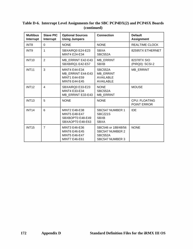
172 Appendix D Standard Definition Files for the iRMX III OS
Table D-6. Interrupt Level Assignments for the SBC PCP4DX(2) and PCP4SX Boards(continued)
MultibusInterrupt
Slave PICInterrupt
Optional SourcesUsing Jumpers
Connection DefaultAssignment
INT8 0 NONE NONE REALTIME CLOCK
INT9 1 SBXAIRQ0 E24-E23MINT4 E24-E34
SBXASBC552A
82595TX ETHERNET
INT10 2 MB_ERRINT E42-E43SBXBIRQ1 E42-E57
MB_ERRINTSBXB
82378TX SIO(PIRQ0): SCSI-2
INT11 3 MINT4 E44-E34MB_ERRINT E44-E43MINT1 E44-E59MINT6 E44-E45
SBC552AMB_ERRINTAVAILABLEAVAILABLE
MB_ERRINT
INT12 4 SBXAIRQ0 E33-E23MINT4 E33-E34MB_ERRINT E33-E43
NONESBC552AMB_ERRINT
MOUSE
INT13 5 NONE NONE CPU: FLOATINGPOINT ERROR
INT14 6 MINT2 E48-E38MINT5 E48-E47SBXBOPT0 E48-E49SBXAOPT0 E48-E63
SBC547 NUMBER 1SBC221SSBXBSBXA
IDE
INT15 7 MINT3 E46-E36MINT6 E46-E45MINT5 E46-E47MINT7 E46-E61
SBC546 or 188/48/56SBC547 NUMBER 2SBC552ASBC547 NUMBER 3
NONE

ICU User’s Guide and Quick Reference Appendix D 173
I/O Controller Board SupportTable D-7 shows the I/O controller support for the standard definition files.Whenever more than one I/O board is listed, you may use only one of the I/Ocontrollers in the system because they use a common system resource (such as aninterrupt level or a port address) that cannot be shared. If you need to use a differentcombination of I/O controllers, you can either create a new definition file or modifyone of the standard definition files. Depending on what changes you make to thedevice configuration screens in the definition files, you may need to jumper the I/Ocontrollers differently than described in this manual.
See also: Command Reference, for the default device names supported in theStandard Definition Files
Table Error! Reference source not found.-7. I/O Controller Support for Multibus IDefinition Files
CPU Board I/O Controller Support
SBC 386/12, 386/12S, 486/12,and 486/12S
8274 Channels A and B
SBC 544A or 548 orSBC 188/48 or 188/56
SBC 214 orSBC 215G/SBX 217C/218ASBC 221 or 221S
On-board SCSI (SBC 386/12Sand 486/12S only)
SBC 386/2X and 3863Xin a System 320 Microcomputer
8251A
SBC 546 (includes line printer and globalclock)
SBC 547 number 1
SBC 547 number 2
SBC 547 number 3
SBC 548, 188/48 or 188/56
SBC 214 orSBC 215G/SBX 217C/218A orSBC 221 or 221S
SBC PCP4DX(2) and PCP4SX None

174 Appendix D Standard Definition Files for the iRMX III OS
Multibus I Operating System Layer ConfigurationDepending on the OS layer, configuration aspects for the definition files differ. Thislist points out the differences for OS layers:
Nucleus All definition files define the Nucleus identically except forNPX definition.
SDM The iRMX III OS uses the SDM monitor for its low leveldebug support. All standard definition files except pcp4s.bckselect the serial channel on the CPU board as the primarySDM serial channel. The file pcp4s.bck uses the COM1channel as the primary SDM serial channel.
System Debugger The iRMX III SDB is defined identically in the standarddefinition files for all Multibus I systems. Interrupt level 1(encoded level 18H) on the master PIC is used to enter theSDB. To use the SDB, your system must include the SDMmonitor.
BIOS The iRMX III BIOS is defined identically, except for theGlobal Clock parameter, in all but the pcp4s.bck standarddefinition files.
In the pcp4s.bck definition file the Tape Support, BIOS PoolMinimum, Number of Loadable Devices, and Number ofLoadable Device Units as well as the Global Clock are defineddifferently than on other Multibus I standard definition files.

ICU User’s Guide and Quick Reference Appendix D 175
EIOS The iRMX III EIOS is defined identically, except for the lineprinter physical name, in all but the pcp4s.bck standarddefinition files. The line printer physical device name does notapply in the pcp4s.bck definition file.
Physical DeviceName
LogicalName Definition Files For
bb (Byte Bucket) :bb: All boards
stream :stream: All boards
w0 or BootstrapDevice
:sd: All boards
lp :lp: SBC 386/12, 386/12S,486/12, 486/12S
t546_lp :lp: SBC 386/2X/3X boards
Application Loader The iRMX III AL is defined identically in the standarddefinition files.
UDI The iRMX III UDI is defined identically in the standarddefinition files. There are no configurable parameters to theUDI.
Human Interface The iRMX III HI is defined identically in the standarddefinition files.
Initially, one terminal is configured for use by HI users. Youcan add more terminals to all boards by modifying the file:config:terminals. Tables Error! Reference source notfound.-8 and Error! Reference source not found.-9 list themaximum number of terminals that can be supported by thesystems defined by the standard definition files. The differentcombinations indicate the different types of terminalcontrollers which may be used at the same time. If a differentcombination is needed, you must run the ICU to change theinterrupt level, flag byte address, and the dual-port bufferaddresses of the necessary terminal controller boards.
For the pcp4s.bck definition file, the default supported terminaldevice is the console (physical device d_cons). In addition tothis device, the SBC PCP4DX, PCP4SX, and PCP4DX2boards can support an additional user on both the COM1 andCOM2 serial devices. Thus, the pcp4s.bck definition file cansupport up to three users.

176 Appendix D Standard Definition Files for the iRMX III OS
Table D-8. Terminal Support for the SBC 386/2X/3X Boards
Terminal DeviceComb.
#1Comb.
#2Comb.
#3Comb.
#4
CPU board 1 user 1 user 1 user 1 user
SBC 546 4 users 4 users 4 users
SBC 547 #1 8 users 8 users 8 users
SBC 547 #2 8 users 8 users
SBC 547 #3 8 users
SBC 188/48 or SBC 188/56 8 users
TOTAL USERS 13 users 21 users 29 users 9 users
Table D-9. Terminal Support for the SBC 386/12(S) and 486/12(S) Boards
Terminal Device Comb.#1
Comb.#2
Comb.#3
CPU board 2 users 2 users 2 users
SBC 544A 4 users
SBC 188/48 or SBC 188/56 8 users
SBC 548 8 users
TOTAL USERS 6 users 10 users 10 users
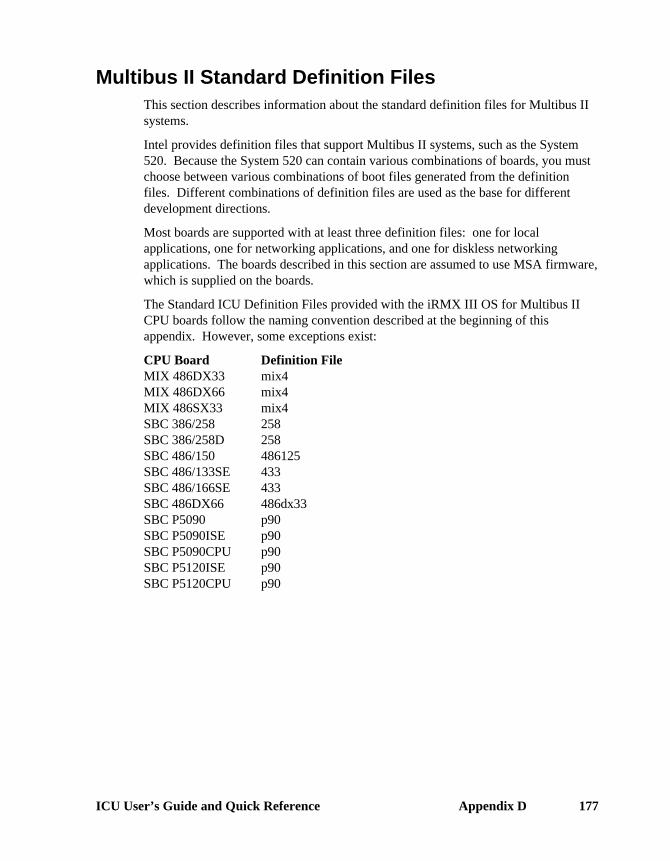
ICU User’s Guide and Quick Reference Appendix D 177
Multibus II Standard Definition FilesThis section describes information about the standard definition files for Multibus IIsystems.
Intel provides definition files that support Multibus II systems, such as the System520. Because the System 520 can contain various combinations of boards, you mustchoose between various combinations of boot files generated from the definitionfiles. Different combinations of definition files are used as the base for differentdevelopment directions.
Most boards are supported with at least three definition files: one for localapplications, one for networking applications, and one for diskless networkingapplications. The boards described in this section are assumed to use MSA firmware,which is supplied on the boards.
The Standard ICU Definition Files provided with the iRMX III OS for Multibus IICPU boards follow the naming convention described at the beginning of thisappendix. However, some exceptions exist:
CPU Board Definition FileMIX 486DX33 mix4MIX 486DX66 mix4MIX 486SX33 mix4SBC 386/258 258SBC 386/258D 258SBC 486/150 486125SBC 486/133SE 433SBC 486/166SE 433SBC 486DX66 486dx33SBC P5090 p90SBC P5090ISE p90SBC P5090CPU p90SBC P5120ISE p90SBC P5120CPU p90

178 Appendix D Standard Definition Files for the iRMX III OS
Multibus II File ApplicationsMost boards are supported with several definition files: one for local applications,one or two for networking applications, one for diskless networking applications, andone for I/O applications. This list describes the different types of applications:
Local Configurations of the iRMX III OS which use only theresources of the chassis in which the CPU board is located.
The definition files for local applications consist only of theCPU board name. The target files they create include nonetworking software. A dedicated hard disk for the systemdevice :sd: is required.
COMMengine Network configurations of the iRMX III OS which use a CPUboard and a separate Ethernet controller board. This is trueeven for boards that have an on-board Ethernet controller. TheOS can access resources both inside and outside the chassisthat contains the CPU board. The iRMX-NET software isconfigured both as a file server and consumer to provide LANaccess. A dedicated hard disk for the system device :sd: isrequired. The definition files for COMMengine networkingapplications consist of the name of the CPU board with netappended.
COMMputer Network configurations of the iRMX III OS that use a CPUboard that also provides an Ethernet controller. These CPUboards require an on-board Ethernet controller. The OS canaccess resources both inside and outside the chassis thatcontains the CPU board. The iRMX-NET software isconfigured to be both a file server and client to provide accessto the LAN. The on-board Ethernet controller is controlled bythe iRMX-NET job which is selected in these definition files.The appropriate iTP4 module is combined with iRMX-NETautomatically. A dedicated hard disk for the system device:sd: is required. The definition file names for COMMputernetworking applications consist of the name of the board withcp appended.

ICU User’s Guide and Quick Reference Appendix D 179
Diskless Network configurations of the iRMX III OS that use a CPUboard and a separate Ethernet controller board. The OS canaccess resources both inside and outside the chassis thatcontains the CPU board. The iRMX-NET software is a fileclient only providing LAN access. A hard disk controlled byanother CPU board, either in the same chassis or in a differentchassis, is required for the system device :sd:, a RemoteSystem Device (RSD). This disk can be shared with otherCPU boards. The definition files for diskless networkingapplications consist of the name of the CPU board with rsd ormsd appended. I/O server boards that have an on-board SCSIsubsystem do not have corresponding definition files fordiskless applications.
I/O Configurations of the iRMX III OS that provide Multibus IIclients access to the resources on an I/O board such as SCSI,networking, and serial controllers. The target files defined bythese definition files are used on the associated I/O board inconjunction with other boards in a Multibus II system. Forexample, a CPU board running either the iRMX or the UNIXoperating system could access disks controlled by an iRMXI/O configuration running on an I/O server board.
These applications do not include an HI or AL and do notrequire a system device. They do not require any systemresources beyond those located on their local board. Theapplication defined by each definition file fully supports all ofthe I/O capabilities of the associated board. These applicationsare designed to be boot loaded with the MSA Bootstrap Loaderor PROMmed.

180 Appendix D Standard Definition Files for the iRMX III OS
Table Error! Reference source not found.-10 shows which definition files can beused to create which types of applications.
Table D-10. Multibus II Application Types and Definition Files
Application Definition File CPU Board
Local 386020.bck 1
386020a.bck486020a.bckmix4.bck386120.bck386133.bck258s.bck486125.bck433.bck433s.bck486dx33.bck486sx25.bckp90s.bck
MIX 386/020MIX 386/020AMIX 486/020AMIX 486DX33, 486DX66 and 486SX33SBC 386/116 and 386/120SBC 386/133SBC 386/258 and 386/258DSBC 486/125 and 486/150SBC 486/133SE and 486/166SESBC 486/133SE and 486/166SESBC 486DX266 and 486DX33SBC 486SX25SBC P5090ISE, P5090, and P5120ISE
COMMengine 386020net.bck386020anet.bck486020anet.bckmix4net.bck386120net.bck386133net.bck258snet.bck486125net.bck433net.bck 3
486dx33net.bck486sx25net.bckp90net.bck
MIX 386/020MIX 386/020AMIX 486/020AMIX 486DX33, 486DX66 and 486SX33SBC 386/116 and 386/120SBC 386/133SBC 386/258 and 386/258DSBC 486/125 and 486/150SBC 486/133SE and 486/166ESBC 486DX266 and 486DX33SBC 486SX25SBC P5090ISE, P5090CPU, P5090,P5120ISE, and P5120CPU
continued

ICU User’s Guide and Quick Reference Appendix D 181
Table D-10. Multibus II Application Types and Definition Files (continued)
Application Definition File CPU Board
COMMputer 386020cp.bck386020acp.bck486020acp.bckmix4cp.bck433cp.bck 4
433scp.bck 2
433scpp.bck 2
486dx33cp.bck486sx25cp.bckp90cp.bckp90scp.bckp90scpp.bck
MIX 386/020MIX 386/020AMIX 486/020AMIX 486DX33, 486DX66 and 486SX33SBC 486/133SE 4 and 486/166SESBC 486/133SE 4 and 486/166SESBC 486/133SE 4 and 486/166SESBC 486DX266 and 486DX33SBC 486SX25SBC P5090ISE, P5090 and P5120ISESBC P5090ISE, P5090 and P5120ISESBC P5090ISE, P5090 and P5120ISE
Diskless 386020rsd.bck 5
386020arsd.bck 5
486020arsd.bck 5
mix4rsd.bck 5
386120rsd.bck386133rsd.bck486125rsd.bck433rsd.bck433msd.bck486dx33rsd.bck486sx25rsd.bckp90rsd.bck
MIX 386/020MIX 386/020AMIX 486/020AMIX 486DX33, 486DX66 and 486SX33SBC 386/116 and 386/120SBC 386/133SBC 486/125 and 486/150SBC 486/133SE and 486/166SESBC 486/133SE and 486/166SESBC 486DX266 and 486DX33SBC 486SX25SBC P5090ISE, P5090CPU, P5090,P5120ISE, and P5120CPU
I/O 386020io.bck 7
386020aio.bck486020aio.bck 5
mix4io.bck258io.bck 8
433io.bck 7 8
p90io.bck
MIX 386/020 6
MIX 386/020A 6
MIX 486/020A 6
MIX 486DX33, 486DX66 and 486SX33SBC 386/258 and 386/258DSBC 486/133SE and 486/166SESBC P5090ISE, P5090 and P5120ISE

182 Appendix D Standard Definition Files for the iRMX III OS
1 The 386020.bck file defines a minimal target file with no networking. It treats the MIXbaseboard as a CPU board.
2 The target files created by the 433scp.bck and 433scpp.bck files treat an SBC 486/133SE or486/166SE board as a single board system. They allow the board to act as both an I/Oserver board and a CPU board. They contain iRMX-NET, the PCI Server, and theatcs/279/arc Server. They can be booted when the board is in slot 0. The definition filesselect iRMX-NET in a COMMputer configuration. If iRMX-NET is not required, use 433s.bck.
3 The target file created by the 433net.bck file treats an SBC 486/133SE or 486/166SE boardas a CPU board, not as an I/O Server board. The target file does not contain a PCI Server oratcs/279/arc Server. Because of this, it cannot automatically be booted on a 486/133SE or486/166SE acting as an I/O Server board in slot 0. Boards in slot 0 are assumed to provideaccess to SCSI peripherals through the PCI Server, and access to some sort of systemconsole through the atcs/279/arc Server.
4 The target file created by the 433cp.bck file treats a 486/133SE or 486/166SE board as aCPU board, not as an I/O server. The target file does not contain a PCI Server oratcs/279/arc Server. Because of this, it cannot automatically be booted on a 486/133SE or486/166SE acting as an I/O Server in slot 0. Boards in slot 0 are assumed to provide accessto SCSI peripherals through the PCI Server, and access to some sort of system consolethrough the atcs/279/arc Server. You can also use 433scp.bck or 433scpp.bck as anotheroption for a COMMputer configuration definition file for the 486/133SE or 486/166SE board.
5 The MIX remote system device definition files (386020rsd.bck, 386020arsd.bck,486020arsd.bck, mix4rsd.bck) create target files that require a separate Ethernet controller,even though the MIX 560 board could provide that service.
6 Up to three MIX 450 modules and one MIX 560 module in any combination can be mountedon a MIX baseboard.
7 The 386020io.bck, 486020io.bck, 433io.bck, and mix4io.bck files can be used to create targetfiles that when booted on the associated board provide an Ethernet controller which otherCPU boards can access as a COMMengine.
8 The 258io.bck and 433io.bck files create target files that can be booted on the associated I/OServer board in slot 0.

ICU User’s Guide and Quick Reference Appendix D 183
Default OS Layer and Jobs for Multibus II Definition FilesTable D-11 shows the default OS layers and first-level jobs configured into eachMultibus II definition file. The columns in Table D-11 indicate which ICU screensthe OS layers and jobs are configured on: SUB, SYSJ, and NET. Each of thecolumns within these three columns represents a layer of the iRMX OS or a first-level job. A shaded cell means the layer or job is configured in the definition file,while a clear cell means the layer or job is not configured. The following listprovides a key for Table D-11.
Column Layer or Job
A50 ATCS/450 Server JobAL Application LoaderATC ATCS/279/ARC Server JobBIO Basic I/O SystemBS Multibus II Bootserver JobCLB Shared C LibraryCMJ iNA 960 COMMengineDL Multibus II Downloader JobEIO Extended I/O SystemFPI Front-Panel Interrupt Server JobHI Human InterfaceMIP iNA 960 MIPOE OS ExtensionsPCI PCI Server JobPGS Paging SubsystemRCJ iRMXNET ClientRSJ iRMXNET ServerSDM System Debug Monitor and System DebuggerSSK Soft-Scope Kernel JobSUB Multibus II Multiple Subnet SupportTCP TCP/IPUDI Universal Development InterfaceVMD VM86 DispatcherXCJ X.25 ClientXSJ X.25 Server

184 Appendix D Standard Definition Files for the iRMX III OS
Table D-11. OS Layer and Jobs in Multibus II Definition Files
SUB Screen SYSJ Screen NET Screen
File UDI
CLB
HI
AL
EIO
BIO
PGS
VMD
SDM
OE
PCI
DL
ATC
A50
BS
FPI
SSK
MIP
CMJ
SUB
RCJ
RSJ
TCP
XSJ
XCJ
258s
258snet
258io
386020
386020cp
386020net
386020rsd
386020io
386020a
386020acp
386020anet
386020arsd
386020aio
386120
386120net
386120rsd
386133
386133net
386133rsd
433
433cp
433net
continued

ICU User’s Guide and Quick Reference Appendix D 185
Table D-11. OS Layer and Jobs in Multibus II Definition Files (continued)
SUB Screen SYSJ Screen NET Screen
File UDI
CLB
HI
AL
EIO
BIO
PGS
VMD
SDM
OE
PCI
DL
ATC
A50
BS
FPI
SSK
MIP
CMJ
SUB
RCJ
RSJ
TCP
XSJ
XCJ
433rsd
433msd
433io
433s
433scp
433scpp
433scp2
486020a
486020acp
486020anet
486020arsd
486020aio
mix4
mix4cp
mix4cp2
mix4net
mix4rsd
mix4io
mixx25
p90
p90cp
p90net
p90rsd
p90msd
p90io
p90s
p90scp
p90scpp
p90scp2

186 Appendix D Standard Definition Files for the iRMX III OS
continued

ICU User’s Guide and Quick Reference Appendix D 187
Table D-11. OS Layer and Jobs in Multibus II Definition Files (continued)
SUB Screen SYSJ Screen NET Screen
File UDI
CLB
HI
AL
EIO
BIO
PGS
VMD
SDM
OE
PCI
DL
ATC
A50
BS
FPI
SSK
MIP
CMJ
SUB
RCJ
RSJ
TCP
XSJ
XCJ
486dx33
486dx33cp
486dx33net
486dx33rsd
486125
486125net
486125rsd
Memory Addresses Used in Multibus II Standard DefinitionFiles
The default memory addresses used by the iRMX III OS, defined in the standarddefinition files, are listed below. If you develop a custom application which does notuse the hardware supported in the standard definition files, you may use the memoryaddresses for other functions. You may also assign other memory addresses to thefunction if required.
Start End Function0H 0FFFFH Firmware Data10000H 0FFEFFFFFH OS and Application Code and data0FFF00000H 0FFFFFFFFH EPROM space (SDM, IDX, MSA Bootstrap
Loader)

188 Appendix D Standard Definition Files for the iRMX III OS
Multibus II Operating System Layer ConfigurationDepending on the OS layer, configuration aspects for the Multibus II definition filesdiffer. This list points out the differences for OS layers:
Nucleus The iRMX III Nucleus is defined identically in the standardMultibus II definition files except for RAM, MPC, ADMA,and DAG configuration which is different for each file.
• MIX n86/020A, MIX 486DX33, and MIX 486SX33 useenhanced implicit bus arbitration mode.
System Debugger The iRMX III SDB is defined identically in the standarddefinition files for all Multibus II systems. To use the SDB,your system must include the SDM monitor.
BIOS The iRMX III BIOS is defined identically, except for theGlobal Clock parameter, in the standard definition files.
EIOS The iRMX III EIOS is defined identically, except for the lineprinter physical name, in the standard definition files.
These logical devices are attached by the EIOS when it isinitialized:
PhysicalDevice Name
LogicalName
DefinitionFile
bb (byte bucket) :bb: Allstream :stream: Allscw :sd: AllNo line printer configured --- 386120.bck
Application Loader The iRMX III AL is defined identically in the standarddefinition files.
Human Interface The iRMX HI is defined identically in the standard definitionfiles.
The ATCS driver can be used to configure terminal devices.
See also: ATCS Driver, System Configuration andAdministration
UDI The iRMX III UDI is defined identically in the standarddefinition files. There are no configurable parameters to theUDI.

ICU User’s Guide and Quick Reference Appendix D 189
PC Standard Definition FilesThis section describes information about the standard definition files for PC systems.
Intel provides definition files that support DOSRMX and PCs that run on a PCmotherboard. You can choose between various combinations of boot files generatedfrom the definition files for your particular system. Different combinations ofdefinition files are used as the base for different development directions.
The Standard ICU Definition Files provided with the iRMX III OS for Windows andPCs are:
Definition File Systempc.bck PC Platforms (including SBC PCP4DX, PCP4SX,
PCP4DX2, SBC 486SX25, 486DX33, SBC P5090,P5090ISE, and P5090CPU with BIOS boot enabled)
pccp.bck EtherExpress™ Class Networkingpccprsd.bck EtherExpress Class Networkingpcnet.bck PCL2 and PCL2A Networkingpcp90.bck SBC P5090, P5090ISE, P5090CPU, SBC P5120ISE, and
P5120CPU
PC ApplicationsPC definition files support several applications: one for local applications, one ortwo for networking applications, and one for diskless networking applications. Thislist describes the different types of applications:
Local Configurations of the iRMX III OS which use only theresources of the chassis in which the CPU board is located.
The definition files for local applications include pc.bck andpcp90.bck. The target files they create include no networkingsoftware. A dedicated hard disk for the system device :sd: isrequired.

190 Appendix D Standard Definition Files for the iRMX III OS
COMMengine Network configurations of the iRMX III OS which use a CPUboard and a separate Ethernet controller board. This is trueeven for boards that have an on-board Ethernet controller. TheOS can access resources both inside and outside the chassisthat contains the CPU board. The iRMX-NET software isconfigured both as a file server and consumer to provide LANaccess. A dedicated hard disk for the system device :sd: isrequired. The definition file for COMMengine networkingapplications is pcnet.bck.
COMMputer Network configurations of the iRMX III OS that use a CPUboard that also provides an Ethernet controller. These CPUboards require an on-board Ethernet controller. The OS canaccess resources both inside and outside the chassis thatcontains the CPU board. The iRMX-NET software isconfigured to be both a file server and client to provide accessto the LAN. The on-board Ethernet controller is controlled bythe iRMX-NET job which is selected in these definition files.The appropriate iTP4 module is combined with iRMX-NETautomatically. A dedicated hard disk for the system device:sd: is required. The definition file for COMMputernetworking applications is pccp.bck.
Diskless Network configurations of the iRMX III OS that use a CPUboard and a separate Ethernet EtherExpress class controllerboard. The OS can access resources both inside and outsidethe chassis that contains the CPU board. The iRMX-NETsoftware is a file client only providing LAN access. A harddisk controlled by another CPU board, either in the samechassis or in a different chassis, is required for the systemdevice :sd:, a Remote System Device (RSD). This disk can beshared with other CPU boards. The definition file for disklessnetworking applications is pccprsd.bck.

ICU User’s Guide and Quick Reference Appendix D 191
Table D-12 summarizes which definition files can be used to create which types ofapplications.
Table D-12. PC Application Types and Definition Files
Application Definition File
LocalLocalCOMMputerCOMMputer and remoteCOMMengine
pc.bckpcp90.bckpccp.bckpccprsd.bckpcnet.bck

192 Appendix D Standard Definition Files for the iRMX III OS
Default OS Layer and Jobs for PC Definition FilesTable D-13 shows the default OS layers and first-level jobs configured into each PCdefinition file. The columns in Table D-13 indicate which ICU screens the OS layersand jobs are configured on: SUB, SYSJ, and NET. Each of the columns within thesethree columns represents a layer of the iRMX OS or a first-level job. A shaded cellmeans the layer or job is configured in the definition file, while a clear cell means thelayer or job is not configured. The following list provides a key for Table D-13.
Column Layer or Job
A50 ATCS/450 Server JobAL Application LoaderATC ATCS/279/ARC Server JobBIO Basic I/O SystemBS Multibus II Bootserver JobCLB Shared C LibraryCMJ iNA 960 COMMengineDL Multibus II Downloader JobEIO Extended I/O SystemFPI Front-Panel Interrupt Server JobHI Human InterfaceMIP iNA 960 MIPOE OS ExtensionsPCI PCI Server JobPGS Paging SubsystemRCJ iRMXNET ClientRSJ iRMXNET ServerSDM System Debug Monitor and System DebuggerSSK Soft-Scope Kernel JobSUB Multibus II Multiple Subnet SupportTCP TCP/IPUDI Universal Development InterfaceVMD VM86 DispatcherXCJ X.25 ClientXSJ X.25 Server

ICU User’s Guide and Quick Reference Appendix D 193
Table D-13. OS Layer and Jobs in PC Definition Files
SUB Screen SYSJ Screen NET Screen
File UDI
CLB
HI
AL
EIO
BIO
PGS
VMD
SDM
OE
PCI
DL
ATC
A50
BS
FPI
SSK
MIP
CMJ
SUB
RCJ
RSJ
TCP
XSJ
XCJ
pc
pccp
pccprsd
pcnet
pcp90
PC Operating System Layer ConfigurationDepending on the OS layer, configuration aspects for the PC definition files differ.This list points out the differences for OS layers:
Nucleus The iRMX III Nucleus is defined identically in the standardPC definition files.
System Debugger The iRMX III SDB is defined identically in the standarddefinition files for PC systems. To use the SDB, your systemmust include the SDM monitor.
BIOS The iRMX III BIOS is defined identically in the standard PCdefinition files.
EIOS The iRMX III EIOS is defined identically in the standard PCdefinition files.
These logical devices are attached by the EIOS when it isinitialized:
PhysicalDevice Name
LogicalName
DefinitionFile
bb (byte bucket) :bb: Allstream :stream: All
194 Appendix D Standard Definition Files for the iRMX III OS
Application Loader The iRMX III AL is defined identically in the standard PCdefinition files.
Human Interface The iRMX HI is defined identically in the standard PCdefinition files.
UDI The iRMX III UDI is defined identically in the standard PCdefinition files. There are no configurable parameters to theUDI.
■■ ■■ ■■

ICU User’s Guide and Quick Reference Index 195
Index
The Parameter Index is followed by a General Index(A30), 107(A50), 109(A54), 107(A74), 107(ABR), 56(AC), 110(ACE), 48(ACI), 99(ACO), 99(Actual name), 89(ADP), 48(AIB), 99(AL), 105(ALF), 69(ALN), 90(ASC), 47(ATC), 109(ATT), 86(B30), 107(B54), 107(B74), 107(BA), 111(BAA), 116(BAB), 76, 79(BAO), 76, 79(BBS), 87(BIF), 69(BIOS), 105(BIP), 63(BOF), 111(BON), 111(BS), 109(BUS), 62(BVC), 85(CBI), 78, 82, 85(CBN), 75, 79, 82, 85(CBS), 87
(CBT), 83(CC), 76, 78, 79(CD), 56, 76, 77, 79, 91(CEBN), 78(CET), 75(CF), 63, 114(CIB), 91(CIL), 62, 114(CIN), 62(CIO), 91, 103(CLB), 105(CLC), 91(CLIB), 69(CLJ), 75, 81, 82, 85(CLN), 91(CMM), 116(CMP), 73(CN), 62, 114(CNM), 64(CNN), 91(CNP), 91(CON), 48, 108(COS), 82(CPI), 102(CPN), 91(CRO), 102(CRS), 102(CS), 95(CSB), 76(CSO), 76(CST), 48(CTA), 83(CUT), 48(D51), 107(DDA), 99(DDP), 99(DDS), 56, 60, 82, 83

196 Index
(DEF), 66(DEH), 95(DEV), 51, 52(Device Name), 88(device_name), 57(DFD), 57, 60(DHH), 95(DHI), 96(DIB), 99(DL), 109(DLN), 57(DMA), 111(DMP), 47(DN), 76, 78, 79(DO), 57(DOB), 99(DOM), 93(DPD), 86(DPN), 53, 57(DPT), 96(DRQ), 60, 82(DTF), 69(DTN), 65(DU), 59, 114(DUP), 53(EBS), 60, 82(EDF), 87(EFD), 60(EHS), 59, 118(EIF), 69(EIOS), 105(EM), 59, 95, 118(EMU), 63(EOR), 102(EPN), 101(ER), 112(ESC), 107(FCT), 93(FD), 112(FIL), 115(file_driver), 57(FN), 76, 78, 79(FPI), 109(FSN), 85(FST), 92(G79), 107(GBR), 99
(GC), 48(GCN), 49(GDR), 99(GSN), 101(HBA), 76(HI), 105(HIF), 69(high), 72(HSE), 95(ICL), 64(IF), 63(IJD), 59, 114(IL), 51, 75, 79(ILF), 69(INT), 111(IPP), 66(IS), 70(ISL), 69(ISS), 60, 82(ITI), 92(ITP), 51, 56, 60, 82, 83(JEI), 83(JST), 65(KTR), 62(L0O), 111(LBS), 77(LCN), 60(LD), 75, 78, 79, 90(LDU), 48(LDV), 48(Level_Sensitive), 70(LI), 83(LLN), 90(LO), 93(logical name), 57(Logical name), 89(Logical Name), 88(logical_name), 67(low), 72(LPN), 90(LSE), 95(LUL), 90(MAX), 65, 66(MBS), 103(MC1)-(MC6), 92(MCE), 95(MCO), 98

ICU User’s Guide and Quick Reference Index 197
(MCT), 98(MD), 90(MDC), 99(MDL), 98(MDP), 98(MDS), 98(MDV), 86(MDW), 113(MFD), 60(MI), 110(MIN), 65, 66(MIP), 73(MJN), 75(MLN), 90(MNF), 69(MOB), 54, 74, 80, 82, 84, 110, 113, 114, 115,
116, 118(Module), 118(MP), 70(MPD), 86(MPN), 90(MPR), 54, 74, 80, 82, 84, 110, 113, 114, 115,
116, 118(MPS), 70(MRR), 83(MSC), 83(MSM), 96(MST), 96(MSW), 113(MTK), 54, 74, 80, 82, 84, 110, 113, 114, 115,
116, 118(MTP), 66(MUL), 90(NAM), 51, 52, 117(NAT), 86(NBB), 87(NC), 111(NCB), 87(ND), 53(NDU), 53(NEB), 95, 103(NEH), 95(NEM), 75, 77(NET), 69, 105(NFD), 60(NGE), 94(NIE), 94
(NL), 75, 81, 103(NLB), 77(NMI), 95(NO), 92(NOR), 83(NOS), 83(NPX), 59, 65, 74, 81, 82, 85, 93, 118(NR), 93(NRB), 87(NS), 110(NSB), 77, 87(NTM), 100(NUF), 69(ODS), 54, 74, 80, 82, 84, 110, 112, 113, 115,
116, 117(OE), 106(OFN), 81(OFP), 85(OFV), 85(OPN), 53(OPT), 63(OSC), 48(Owner-ID), 58(owners-id), 57(path_name), 67(PCI), 109(PDT), 96(PGS), 105(PID), 77(PMA), 48, 59, 65, 74, 80, 82, 84, 110, 113, 114,
115, 116, 118(PMI), 48, 54, 56, 59, 65, 74, 80, 82, 84, 110,
113, 114, 115, 116, 118(PMT), 96(Port), 70(Prefix), 67(PSC), 86(Public name), 89(PV), 55, 59, 74, 80, 82, 84, 94, 110, 113, 114,
115, 118(PVC), 85(PVL), 92(QS), 77(RAF), 61(RBA), 102(RBF), 61(RBS), 47

198 Index
(RCI), 107(RCJ), 73(RDA), 102(RDT), 77(RES), 111(RET), 93(RIE), 95(RIP), 64(RMB), 61(ROD), 94(ROF), 61(RPA), 56(RQB), 75(RQO), 75(RRP), 95(RRT), 95(RSJ), 73(RSP), 93(RTI), 92(RU), 65(SBS), 77, 87(SC), 85(SCF), 65(SCT), 111(SD), 112(SDB), 106(SDF), 69(SDM), 106(SDN), 112(Separation), 70(SEQ), 116, 117(SGS), 116(SI), 111(SIA), 116(SJM), 70(SL0)-(SL7), 55(Slave_number), 70(SLV), 107(SMI), 48(SN1), 81(SN2), 81(SN3), 81(SN4), 81(SR1)-(SR2), 108(SRC), 102(SS), 64(SSA), 59, 118
(SSI), 55, 59, 74, 80, 82, 84, 110, 113, 114, 115,116, 118
(SSK), 109(STA), 83(STO), 111(STP), 115(SYR), 102(SYS), 64(TCP), 73(TDN), 66(TF), 48(TN), 66(TOP), 53(TP), 55, 59, 62, 74, 80, 82, 84, 110, 113, 114,
118(TPA), 114(TPR), 116(TPS), 63, 114(TSA), 59, 118(TSC), 48(TSP), 48(TTP), 48(TUP), 53(UDF), 69(UDI), 105(UID), 66(UIN), 52(UN), 52(UPC), 103(UPD), 90(user name), 58(USS), 87(UVC), 85(UXC), 64(VAR), 59, 118(VC), 85(VIE), 55(VSE), 102(VSG), 47(VSS), 102(WA), 90(WD), 86(WDI), 99(WDN), 116(WDP), 99(WDT), 64(WFS), 86

ICU User’s Guide and Quick Reference Index 199
(Who Attaches), 88(WP), 75, 79(WTI), 86(WV), 90(XCJ), 73(XS), 111(XSJ), 73.a28, ASM286 source files, 4.a38, ASM386 source files, 4.cf, binder/builder configuration files, 4.csd, submit files, 4:home: logical name, 66?icdev.a38 file, 138?itdev.a38 file, 138
Aabbr field, 137ABDR screen, Automatic Device Boot
Recognition, 57Ability to Create Existing Files parameter, 48aborting commands, <Ctrl-C>, 7Actual name parameter, 89adding
device drivers, 133example, 150
ADMA Base Port Address parameter, 99ADMA Burst Register parameter, 99ADMA Channel for Input parameter, 99ADMA Channel for Output parameter, 99ADMA Delay Register parameter, 99ADMA parameter, 99
Data Port, 99AFA screen, Apex File Access, 86AFAU screen, Afa User, 87AL (Application Loader)
configuring in MB II, 188All System Calls parameter, 47APPL screen, Application Loader, 47Application Image Base Address parameter, 116Application Image Size parameter, 116Application Loader Includes and Lib parameter,
69Application Loader parameter, 105Application Starter Job Initial Memory
parameter, 116
Application Starter Job Maximum Memoryparameter, 116
Application Starter Job Objects parameter, 116Application Starter Job Order parameter, 116ATC50 screen, ATCS/450 Server Job, 113ATCJ screen, ATCS/279/ARC Server, 112ATCS/279/ARC Server Job parameter, 109ATCS/279/ARC system job, 112ATCS/450 Server Job parameter, 109ATCS/450 system job, 113Attach Device Task Priority parameter, 48Attributes parameter, 86Auto Configuration parameter, 110Automatic Boot Device Recognition parameter,
56Automatic Loadname parameter, 90
BB command, 12, 20, 27back command, 20backup command, 12, 27Basic I/O System Includes and Libs parameter,
69BIOFD screen, BIOS File Drivers, 60BIOS
configuring in MB II, 188BIOS parameter, 105BIOS Pool Maximum, Minimum parameter, 48BIOS screen, 48bld, builder files, 4Board Initialization Procedure parameter, 63Boot Address Base parameter, 76, 79Boot Address Offset parameter, 76Boot Address parameter, 79Bootserver system job, 114, 115bootstrap loader, 56BSJ screen, MSA Bootserver Job, 114buffer, command line, 64builder errors, 127builder warnings, 127Burst DMA parameter, 99
CC command, 8, 20C Library Files parameter, 69

200 Index
call gate, 101cancel command, 20cancelling editing session, 7case insensitivity, 7CDF Device parameter, 91CDF Location parameter, 91CDF Logical Name parameter, 91CDF Path Name parameter, 91CDF screen, Client Definition File, 91CEBI screen, 78CEBN screen, 78change command, 8changing
definition files, 8, 18screens, description, 13
Class Code parameter, 76, 78, 79CLI, 64, 66CLIB screen, Shared C Library, 103Client Info Address Base parameter, 91Client Info Address Offset parameter, 91Client Name parameter, 91Client Password parameter, 91Clock Frequency parameter, 63, 114Clock Interrupt Level parameter, 62, 114Clock Interval parameter, 62clock tick, Nucleus, 48Comm Board Instance parameter, 78COMM Board Instance parameter, 82, 85Comm Board Name parameter, 78COMM Board Name parameter, 82, 85Comm Start Address Base parameter, 76Comm Start Address Offset parameter, 76Command Buffer Size parameter, 87command mode, 5Command Name Length parameter, 64COMMengine board instance load method for
MBII, 78COMMengine board Names, 78COMMengine Delay parameter, 76, 77, 79COMMengine Load parameter, 78COMMengine Type parameter, 75Common Update Timeout parameter, 48Communication Board Name parameter, 75, 79COMNT screen, Comments for Build File, 49Configuration Base Time parameter, 83Configuration Directory parameter, 56configuration files, generating, 24
configuring custom device drivers, 133Connect Time Alarm parameter, 83Connection Job Delete Priority parameter, 48Connection Object Size parameter, 82Console I/O parameter, 103Console Port parameter, 108Control-Sequence Translation parameter, 48copy command, 24copying current screen, 24Create Loadable Job parameter, 75, 81, 82, 85creating files for UDS, 135custom board initialization, 63Custom ROM External Procedures parameter,
102Custom ROM Init File parameter, 102
DD command, 11, 21d01 field, 138d01 help field, 138DAG device used parameter, 99data chains, 95Datalink Data Size parameter, 83debugger, 106Default Directory parameter, 66Default Exception Handler parameter, 95Default Host ID parameter, 96Default IO Job Directory Size parameter, 56Default Memory Pool Size parameter, 47Default Number of Port Transactions parameter,
96default prefix, 59Default System Device File Driver parameter,
57Default System Device Logical Name parameter,
57Default System Device Owner's ID parameter,
57Default System Device Physical Name
parameter, 57Default Terminal Name parameter, 65Default User parameter, 59, 114definition files
changing, 18editing, 8listing, example, 40
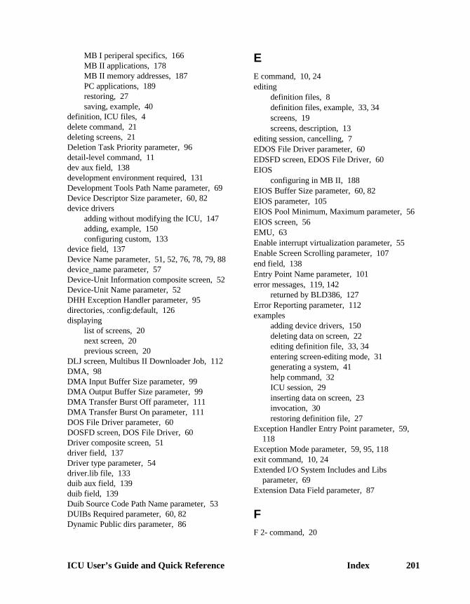
ICU User’s Guide and Quick Reference Index 201
MB I periperal specifics, 166MB II applications, 178MB II memory addresses, 187PC applications, 189restoring, 27saving, example, 40
definition, ICU files, 4delete command, 21deleting screens, 21Deletion Task Priority parameter, 96detail-level command, 11dev aux field, 138development environment required, 131Development Tools Path Name parameter, 69Device Descriptor Size parameter, 60, 82device drivers
adding without modifying the ICU, 147adding, example, 150configuring custom, 133
device field, 137Device Name parameter, 51, 52, 76, 78, 79, 88device_name parameter, 57Device-Unit Information composite screen, 52Device-Unit Name parameter, 52DHH Exception Handler parameter, 95directories, :config:default, 126displaying
list of screens, 20next screen, 20previous screen, 20
DLJ screen, Multibus II Downloader Job, 112DMA, 98DMA Input Buffer Size parameter, 99DMA Output Buffer Size parameter, 99DMA Transfer Burst Off parameter, 111DMA Transfer Burst On parameter, 111DOS File Driver parameter, 60DOSFD screen, DOS File Driver, 60Driver composite screen, 51driver field, 137Driver type parameter, 54driver.lib file, 133duib aux field, 139duib field, 139Duib Source Code Path Name parameter, 53DUIBs Required parameter, 60, 82Dynamic Public dirs parameter, 86
EE command, 10, 24editing
definition files, 8definition files, example, 33, 34screens, 19screens, description, 13
editing session, cancelling, 7EDOS File Driver parameter, 60EDSFD screen, EDOS File Driver, 60EIOS
configuring in MB II, 188EIOS Buffer Size parameter, 60, 82EIOS parameter, 105EIOS Pool Minimum, Maximum parameter, 56EIOS screen, 56EMU, 63Enable interrupt virtualization parameter, 55Enable Screen Scrolling parameter, 107end field, 138Entry Point Name parameter, 101error messages, 119, 142
returned by BLD386, 127Error Reporting parameter, 112examples
adding device drivers, 150deleting data on screen, 22editing definition file, 33, 34entering screen-editing mode, 31generating a system, 41help command, 32ICU session, 29inserting data on screen, 23invocation, 30restoring definition file, 27
Exception Handler Entry Point parameter, 59,118
Exception Mode parameter, 59, 95, 118exit command, 10, 24Extended I/O System Includes and Libs
parameter, 69Extension Data Field parameter, 87
FF 2- command, 20

202 Index
FC screen, File Consumer Configuration, 83File Consumer TSAP ID parameter, 93file driver, 57File Driver parameter, 112File Name parameter, 76, 78, 79File Server Name parameter, 85File Server TSAP ID parameter, 92file_driver parameter, 57find command, 20finding a screen, 20fixed screen format, 14Force DOS Filenames to Lower Case parameter,
60FPI Server Job parameter, 109FPIJ screen, FPI Server Job, 115Free Space Manager memory, 72, 95Front Panel Interrupt Level parameter, 115FS screen, File Server Configuration, 85FSM parameter, 72
GG command, 8, 24, 41GDT entries, 94, 95GDT Slot Number parameter, 101GEN screen, Generate File Names, 61generate command, 8, 24, 41generate command, prefix option, 25generating
configuration files, 24ICU files, 8new system, 24system, example, 41
generating ICU files, 8Global Clock Name parameter, 49Global Clock parameter, 48
HH command, 20HARD screen, Hardware, 62hardware required, 131help command, 20HI (Human Interface)
configuring in MB II, 188HI screen, Human Interface, 64
High GDT/LDT Slot Excluded from FSMparameter, 95
High RAM Address parameter, 102HIJOB screen, Human Interface Jobs, 65HILOG screen, Logical Names, 67Host Buffer Address parameter, 76Human Interface Includes and Libs parameter,
69Human Interface parameter, 105Human Interface Pool Minimum, Maximum
parameter, 65
II command, 23I/O controller boards, 173I/O Job Default Prefix parameter, 59, 114I/O job memory parameters, 65I/O Task Priority parameter, 60, 82, 83I/O Task Size parameter, 82I/O Task Stack Size parameter, 60ICMPJ screen, iNA 960 COMMputer Job, 80ICU
invoking or starting, 5quitting or exiting, 10
ICU generation files, 4icu386.scm file, 3icu386.tpl file, 3ICUMRG (ICU Merge) utility, 134IDEVS screen, Intel Device Drivers, 50IDT entries, 94IMIPJ screen, iNA MIP Driver Job, 74iNA 960 COMMputer job, 80iNA 960 COMMputer parameter, 73iNA 960 MIP Driver parameter, 73iNA COMM Port ID parameter, 77iNA Network Layer parameter, 75, 81iNA Subnet 1 parameter, 81iNA Subnet 2 parameter, 81iNA Subnet 3 parameter, 81iNA Subnet 4 parameter, 81iNA system job, 74ina552a.32L file, 167INCL screen, Includes and Libraries, 69Include 386 CPU Optimizations parameter, 63Includes and Libs parameter, 69including custom device drivers, 133

ICU User’s Guide and Quick Reference Index 203
Initial Command Line Size parameter, 64Initial Program Stack Size parameter, 64Initial Task Priority parameter, 116Initial Task Stack Size parameter, 116initialization error reporting, 95Initialize On-board Functions parameter, 63Initial-Program Pathname parameter, 66Initiator TSAP ID parameter, 92insert command, 23inserting
data on screen, 23new line on screen, 23screen, 23
INT screen, Interrupts, 70Intel Monitor Includes and Libs parameter, 69Intel Support Libraries parameter, 69interconnect register, NMI Enable, 95Interface Libraries parameter, 69Internal EIOS Tasks Priorities parameter, 56Interrupt Level parameter, 51, 75, 79interrupt levels, 168Interrupt Slaves parameter, 70Interrupt Task Priority parameter, 51interrupts
levels in MB I definition files, 168SBC 386/12(S) and 486/12(S) boards, 169,
170, 171invocation
error messages, 120example, 30
invokingICU, 5
example, 30IOJOB screen, I/O Jobs, 59IOUS screen, I/O Users, 58iRMX TCP/IP Job parameter, 73iRMXNET Client JOb parameter, 73iRMX-NET Files parameter, 69iRMX-NET Server Job parameter, 73
JJob Name parameter, 117Job Sequence parameter, 117Jobs Memory Minimum, Maximum parameter,
65
KKernel Tick Ratio parameter, 62
LL command, 9Large Buffer Size parameter, 77, 87LDT entries, 95Level_Sensitive parameter, 70list command, 9listing
definition file, example, 40screen contents, 9
Load parameter, 75, 79Loadable Job Sync. Timeout parameter, 65Local UDF Device parameter, 90Local UDF Location parameter, 90Local UDF Logical Name parameter, 90Local UDF Path Name parameter, 90log files, 28Logical name parameter, 89Logical Name parameter, 88logical_name parameter, 57, 67LOGN screen, Logical Names, 57Logoff Interval parameter, 83Low GDT/LDT Slot Excluded from FSM
parameter, 95Low RAM Address parameter, 102
Mmain menu commands, 7Malloc block size parameter, 103Master Level 0-7 parameter, 55Master PIC port Separation parameter, 70Master UDF Device parameter, 90Master UDF Location parameter, 90Master UDF Logical Name parameter, 90Master UDF Path Name parameter, 90math coprocessor, 59, 65, 74, 81, 82, 85, 93Max No. of Simultaneous Messages parameter,
96Max number of Public Devices parameter, 86Max number of Public Dirs parameter, 86Max. No. of Simultaneous Transactions
parameter, 96

204 Index
Maximum Data Chain Elements parameter, 95Maximum Debug Windows parameter, 113Maximum Memory Required parameter, 66Maximum Number of Objects parameter, 92,
116Maximum Number of Responses parameter, 93Maximum Number of Retries parameter, 93Maximum Number of Tasks parameter, 116Maximum Objects parameter, 54, 74, 80, 82, 84,
110, 113, 114, 115, 118Maximum Priority parameter, 54, 74, 80, 82, 84,
110, 113, 114, 115, 118Maximum Property Value Length parameter, 92Maximum RFD Request parameter, 83Maximum Server Connections parameter, 83Maximum System Windows parameter, 113Maximum Task Priority parameter, 66Maximum Tasks parameter, 54, 74, 80, 82, 84,
110, 113, 114, 115, 118MBII Downloader Job parameter, 109MBII Downloader system job, 112MBII screen, Multibus II Hardware, 98MEMF screen, Memory for Free Space Manager,
72memory restrictions, 71MEMS screen, Memory for System, 72message
address, 96simultaneous, 96solicited, 96trace, 100
Message Device Base Port Address parameter,98
Message Device Port Separation parameter, 98Message Interrupt Level parameter, 98Message Task Priority parameter, 96Minimum Memory Required parameter, 66MIP Configuration
for MBI, 75for MBII, 77for PCs, 79
MIP1 screen, 75MIP2 screen, 77MIX 486DX33 board
definition files, 178MIX 486DX66 board
definition files, 178
MIX 486SX33 boarddefinition files, 178
modifying definition files, 8Module parameter, 118MPC, 98MSA BootServer Job parameter, 109Multibus I
definition files, see Appendix DMultibus I SPC RMX Level parameter, 110Multibus II
definition files, see Appendix Dmemory addresses in definition files, 187
Multicast Address 1-6 parameter, 92
NN command, 20name field, 137Name of EX Handler Object Module parameter,
95Name of Generated MIP Job parameter, 75Name Server Local Only parameter, 93Named File Driver parameter, 60NAMFD screen, Named File Driver, 60naming generation files, 25NCOM screen, Nucleus Communication Service,
96, 97NET screen, Network Subsystem, 73Network Access parameter, 105next command, 20NMI (Non-maskable interrupt), 107NMI Enable Byte parameter, 95NMI Exception Handler parameter, 95non-resident user, 56NPX, 65, 74, 81, 82, 85, 93NS, Name Server Configuration screen, 92NSDOM, Name Server Search Domains screen,
93NUC screen, Nucleus, 94Nucleus and Root Job Includes and Libs
parameter, 69Nucleus clock tick, 48Nucleus Communication Service parameter, 95Number of AFA tasks parameter, 86Number of Binds per VC parameter, 85Number of Command Buffers parameter, 87Number of EIOS buffers parameter, 103

ICU User’s Guide and Quick Reference Index 205
Number of External Mailboxes parameter, 75,77
Number of GDT Entries parameter, 94Number of GDT Slots parameter, 116Number of IDT Entries parameter, 94Number of Large Buffers parameter, 77, 87Number of loadable Device Inits parameter, 48Number of loadable Devices parameter, 48Number of Open Files per process parameter, 85Number of Open Files per VC parameter, 85Number of Outstanding RFD status calls
parameter, 83Number of Outstanding RFD system calls
parameter, 83Number of PCI Server SCSI Controllers
parameter, 110Number of Processes per VC parameter, 85Number of Rbs parameter, 87Number of Small Buffers parameter, 77, 87Number of Trace Messages parameter, 100Number of User Defined Devices parameter, 53Number of User Defined Device-Units
parameter, 53Number of Users per VC parameter, 85Number of Virtual Circuits parameter, 85Numeric Emulator Processor parameter, 63Numeric Library parameter, 103Numeric Processor Extension Used parameter,
59, 65, 74, 81, 82, 85, 93, 118
OObject code pathname parameter, 54object directories, 56Object Directory Size parameter, 54, 74, 80, 82,
84, 110, 112, 113, 115, 117One Cycle DMA parameter, 98OPT, 63OS Extension parameter, 106OSC controls, 48OSEXT screen, OS Extension, 101Owner-ID parameter, 58owners-id parameter, 57
Ppaging identity mapped memory, 72
Paging Subsystem parameter, 105parameter
Job Exit Interval, 83Parameter Validation parameter, 55, 59, 74, 80,
82, 84, 94, 110, 113, 114, 115, 118path_name parameter, 67Pathname for Object Modules parameter, 81PCDEV screen, PC Bus Drivers, 50PCI Server Job parameter, 109PCI system job, 110, 111PCIJ screen, PCI Server Job, 110PCISC screen, PCI Server Job, 111PDEV screen, Public Devices, 88PDIR screen, Public Directory, 89physical device, 57PIC, 62, 98
port, 70slave, 70
PIMM screen, Paging Identity Mapped Memory,72
PIT timer, 62Pool Maximum parameter, 54, 59, 74, 80, 82,
84, 113, 114, 115, 118Pool Minimum parameter, 54, 59, 74, 80, 82, 84,
113, 114, 115, 118Pool Minimum, Maximum parameter, 110Port parameter, 70port transaction, 96PREF screen, Prefixes, 67Prefix parameter, 67Print Spooler Commands parameter, 86priority
EIOS task, 56task, 59
Public name parameter, 89Public Variable Name parameter, 59, 118
QQ command, 10Queue Size parameter, 77quit command, 10
RR command, 11, 21RAM Code File Name parameter, 61

206 Index
Random Access Device and Unit Source CodePath Name parameter, 53
Random Access Object Code Path Nameparameter, 53
RCJ screen, iRMX-Net Client Job, 81Read Buffer Size parameter, 47recovery user, 65, 66redisplay command, 21REM screen, Remote File Access, 83REMFD screen, Remote File Driver, 60Remote Boot File Name parameter, 61Remote Boot Translation parameter, 61Remote Console Interface Driver parameter, 107repetitive screen format, 15repetitive-fixed screen format, 16replace command, 11Report Initialization Errors parameter, 95Request Queue Addr Base parameter, 75Request Queue Addr Offset parameter, 75requirements
hardware, 131software, 132subsystem, 104
RES screen, Resident/Recovery User, 66Resident Initial Program parameter, 64Resident user parameter, 66Resident User parameter, 65Responder TSAP ID parameter, 92Response Delay Time parameter, 77restoring
definition file, 27, 121Retry Timeout parameter, 93Return on Physical Attachdevice parameter, 56returning to command mode, 20ROM Code File Name parameter, 61ROM Copied To RAM parameter, 102ROM Init Code Base Address parameter, 102ROM Init Code RAM Destination Address
parameter, 102ROM Init Code Size parameter, 102ROM or FLASH Execution parameter, 102ROM screen, ROM Code, 102ROM-based system memory restrictions, 72Root Object Directory parameter, 94Round Robin Priority Threshold parameter, 95Round Robin Time Quota parameter, 95RSJ screen, iRMX-NET Server Job, 84
SS command, 9, 21save command, 9saving definition file, example, 40SBC 214 board
MSC driver support, 167SBC 215G board
MSC driver support, 167SBC 221 board
MSC driver support, 167SBC 386/258 board
definition files, 178SBC 386/258D board
definition files, 178SBC 486/133SE board
definition files, 178SBC 486/150 board, definition files, 178SBC 486/166SE board
definition files, 178SBC 486DX66 board
definition files, 178SBC P5090 board
definition files, 178SBC P5090CPU board
definition files, 178SBC P5090ISE board
definition files, 178SBC P5120CPU board
definition files, 178SBC P5120ISE board
definition files, 178SBX 279 Console Controller Driver parameter,
107screen
displaying list of, 20editing commands, 19editing, description, 13elements, 17formats, 13PHYFD, Physical File Driver, 60STRFD, Stream File Driver, 60
screen-editing commands, 7screen-editing mode, 7
example, 31screens
TUPJ, TUPJ Job, 116

ICU User’s Guide and Quick Reference Index 207
SCSI Bus Reset parameter, 111SCSI Bus Scan parameter, 111SCSI Controller Base Address parameter, 111SCSI Controller Interrupt parameter, 111SCSI Controller Time Out parameter, 111SCSI Controller Type parameter, 111SCSI DMA Channel parameter, 111SCSI Identification parameter, 111SCSI Maximum Xfer Rate parameter, 111SCSI Number of CCBs parameter, 111SCSI support for SBC 386/12S and 486/12S
boards, 167SDB
configuring in MB II, 188SDB Interrupt Level parameter, 107SDB screen, System Debugger, 107SDM
address in MB II memory space, 187requirements for SDB, 188
SDM screen, System Debug Console, 107search command, 21searching for string in screen, 21Send Time Alarm parameter, 83Separation parameter, 70Serial Device Name parameter, 112Serial Port parameter, 108Server Concurrency parameter, 85Server Task Priority parameter, 115Shared C Library parameter, 105Slave Level 0-7 parameter, 55SLAVE screen, Slave Interrupt Levels, 70Slave_number parameter, 70Small Buffer Size parameter, 77, 87SoftScope Application Load Path parameter,
116SoftScope Communication parameter, 116SoftScope Kernel job, 116SoftScope Kernel parameter, 109software required, 132SSKJ screen, SoftScope Kernel Job, 116Stack Segment Address parameter, 59, 118Stack Size parameter, 55, 59, 74, 80, 82, 84,
110, 113, 114, 115, 118starting the ICU, 5Storage Device Name parameter, 112SUB screen, Sub-systems, 105Subnet ID parameter, 93
subsystem dependencies, 104SYS parameter, 72SYSJ screen, System Jobs, 109System Bus Type parameter, 62System Command File Name parameter, 65System Debug Monitor parameter, 106System Debugger Includes and Libs parameter,
69System Debugger parameter, 106system device, 57, 64System Directory parameter, 64system generation error messages, 127System in ROM parameter, 102System Jobs
ATCS/279/ARC, 112ATCS/450, 113Bootserver, 114, 115iNA, 74, 80MBII Downloader, 112PCI, 110PCISC, 111SSKJ, 116TPUJ, 116
System Jobs Object Modules parameter, 70system manager, 57System Manager ID parameter, 48system memory, 72
TTape Support parameter, 48Task Entry Point parameter, 59, 118Task Priority ATCS/279/ARC Server job
parameter, 113Task Priority ATCS/450 Server Job parameter,
114Task Priority I/O job parameter, 59Task Priority iNA MIP job parameter, 74, 80Task Priority iRMX-NET job parameter, 82, 84Task Priority MSA Bootserver job parameter,
114Task Priority parameter, 55Task Priority PCI Server job parameter, 110Task Priority User job parameter, 118task, EIOS priority, 56templ_1.uds file, 135templ_2.uds file, 135

208 Index
Terminal Device and Unit Information Namesparameter, 53
Terminal Device and Unit Source Code PathName parameter, 53
Terminal Device Name parameter, 66Terminal Name parameter, 66Terminal Object Code Path Name parameter, 53Terminal OSC Controls parameter, 48Terminal Support Code parameter, 48terminal.lib file, 133testing system after using ICU, 26timeout value parameter, 64Timer Counter Number parameter, 62, 114Timer Port Separation parameter, 63, 114Timer Task Priority parameter, 48Timing Facilities Required parameter, 48transmission interval parameter, 99TSC, 48Two Cycle DMA parameter, 98
Uu01 field, 139u01 help field, 139UDDM screen, UDS Device Driver Modules, 54UDF screen, User Definition File, 90UDI
configuring in MB II, 188UDI parameter, 105UDS (User Device Support) utility, 134uds.scm file, 141unit field, 138Unit Info Name parameter, 51, 52Unit Information Screen composite screen, 51Unit Number on this Device parameter, 52Update UDF parameter, 90User Console I/O Procedure parameter, 103
User Device Support utility, see UDSUser Extension for Intel parameter, 64User ID Number parameter, 66user name parameter, 58User Subsystem parameter, 87USERD screen, User Devices, 53USERJ screen, User Jobs, 117USERM screen, User Modules, 118
Vvalidation of parameter, enabling, 94version control messages, 120version number
files, 120specifying, 137
version numbers, files, 120Virtual Segment Size parameter, 47
WWakeup Port parameter, 75, 79warning messages, 119Watchdog Timer used parameter, 99Who Attaches parameter, 88, 90Who Verifies parameter, 90Wildcard Delete parameter, 86Wildcard File Search parameter, 86Wildcard Wait Interval parameter, 86
XX25 Client Job parameter, 73X25 Server Job parameter, 73xcmdrv.lib file, 150

ICU User’s Guide and Quick Reference Index 209