iris recognition ii. - cvut.cz · iris code projection: doubly-dimensionless polar coordinate...
TRANSCRIPT

IRIS recognition II.Eduard Bakštein,
acknowledgement: Andrzej Drygajlo, EPFL Switzerland
Iris recognition process● Input: image of the eye
● Iris Segmentation
● Projection
● Feature extraction
● Encoding
● Comparison / matching

Iris recognition process
iris image
iris code comparison (database)
iris region segmentation
unwrapping
feature extraction & encoding
Result

Acquiring IRIS image

Visible or Infrared
Visible light● Layers visible● Less texture information● Melanin absorbs visible light
(Near) Infrared light● (NIR)● Melanin reflects most infrared light● More texture isvisible● Preferred for iris recognition systems

Infrared light

NIR illuminationConsider: absorbed heat depends on wavelength
ANSI certified range for illumination:
Common IR LEDs: 880nm, 940nm…
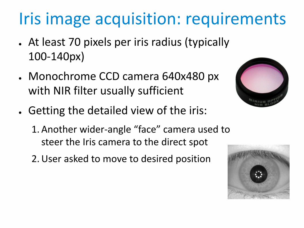
Iris image acquisition: requirements● At least 70 pixels per iris radius (typically
100-140px)
● Monochrome CCD camera 640x480 px with NIR filter usually sufficient
● Getting the detailed view of the iris:
1. Another wider-angle “face” camera used to steer the Iris camera to the direct spot
2. User asked to move to desired position

Segmentation
Aim: find the region of clean iris image
● Annular area between pupil and sclera
● Occlusions by eyelids and eyelashes need to be eliminated
● Easiest modelled by 2 circles

Intra-class variations
pupil dilation
(lighting changes)
inconsistent iris size
(distance from the camera)
eye rotation
(head tilt)
The segmenting algorithm has to address following problems:

Detected Curvilinear boundaries
pupilary boundarylimbic boundary

Curvilinear detectorAssumption: both the pupilary and limbic boundary can be
approximated by (non-concentric) circles(problem: off-axis gaze and specific cases)
Daugman's approach
● searching circle parameters (x0,y0,r) that maximize blurred integro-differential function of the iris image. This maximum is gained when the circle parameters meet either the pupil or limbic properties.
Other possibility
● Hough transform
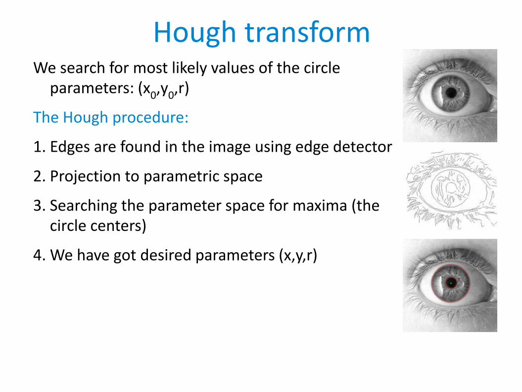
Hough transformWe search for most likely values of the circle
parameters: (x0,y0,r)
The Hough procedure:
1. Edges are found in the image using edge detector
2. Projection to parametric space
3. Searching the parameter space for maxima (the circle centers)
4. We have got desired parameters (x,y,r)
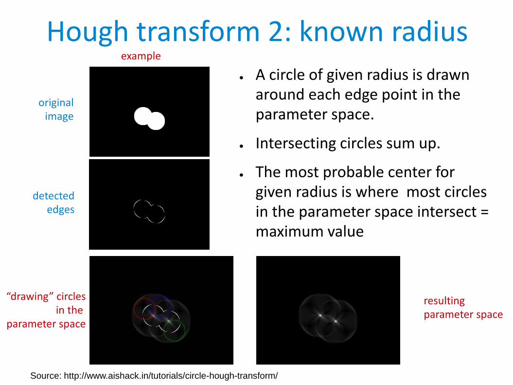
Hough transform 2: known radius● A circle of given radius is drawn
around each edge point in the parameter space.
● Intersecting circles sum up.
● The most probable center for given radius is where most circles in the parameter space intersect = maximum value
example
originalimage
“drawing” circlesin the
parameter space
resultingparameter space
detectededges
Source: http://www.aishack.in/tutorials/circle-hough-transform/

Hough transform 3: known radius
Parameter spaceHere: intensity ~ value(brighter = higher number)
Source: http://www.aishack.in/tutorials/circle-hough-transform/

Hough transform: unknown radius
● Similar procedure
● Slice of parameter space created for each radius
● Searching global maximum
● Computationally intensive
video: http://www.aishack.in/static/img/tut/hough_circle.flv
tutorial: http://www.aishack.in/tutorials/circle-hough-transform/
(slices of the parameter space for different value of diameter r are shown)

Eyelid boundariesSimilar procedures to annular iris region detection can
be used. Many methods exist, e.g.:
● Typical: Daugman's integro-differential operator with splines in place of circles
● Simplest: Hough transform with lines
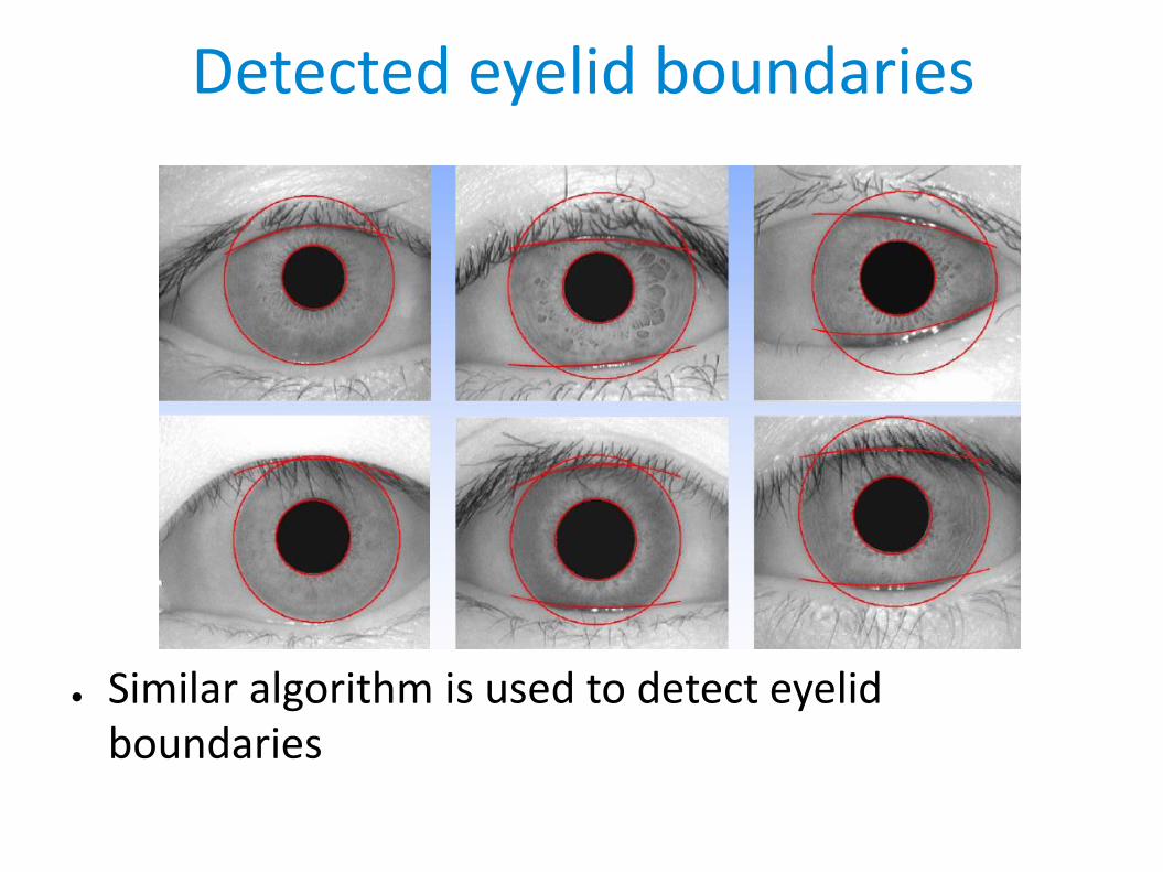
Detected eyelid boundaries
● Similar algorithm is used to detect eyelid boundaries

Projection● The model has to be invariant to iris
size (distance from camera), pupil size (amount of light)
● Invariance to rotation (head tilt) is addressed later in the recognition process
Solution: transformation to (pseudo)radial coordinates
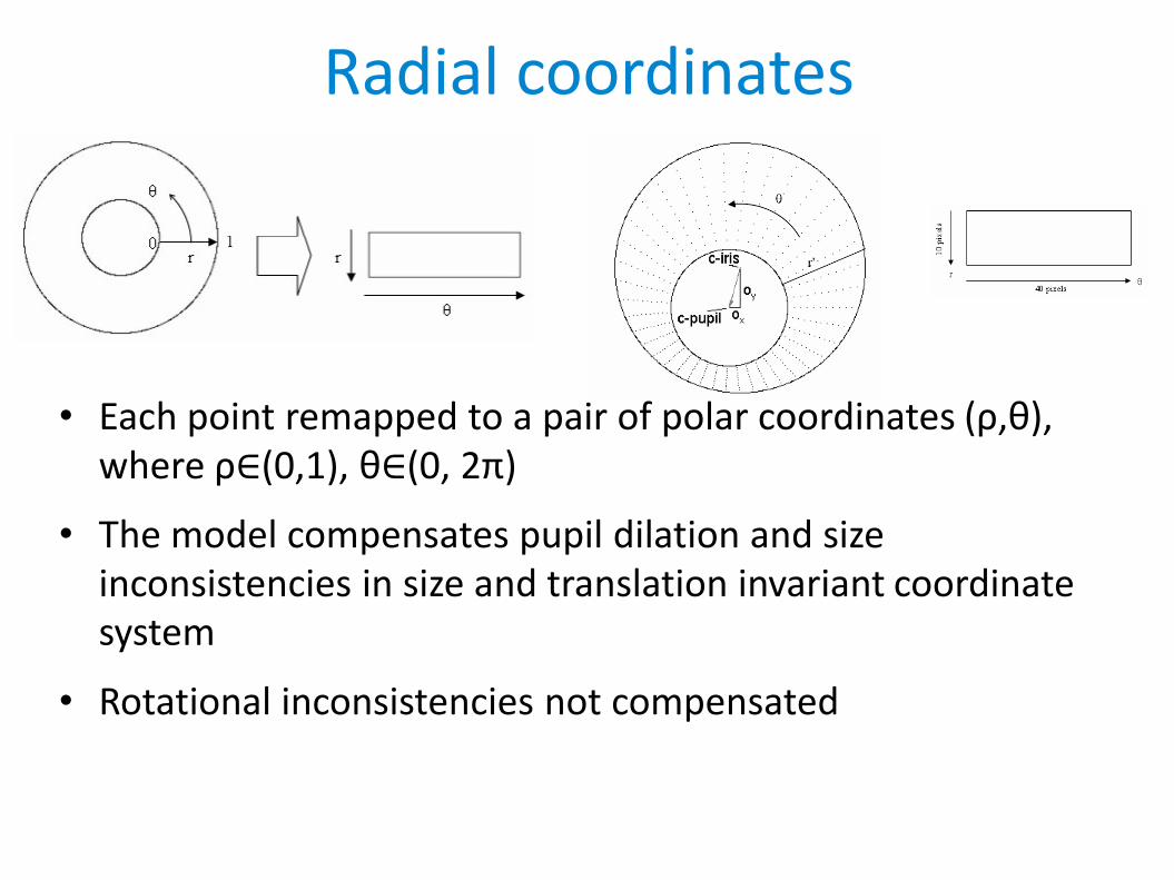
Radial coordinates
• Each point remapped to a pair of polar coordinates (ρ,θ),where ρ∈(0,1), θ∈(0, 2π)
• The model compensates pupil dilation and size inconsistencies in size and translation invariant coordinate system
• Rotational inconsistencies not compensated
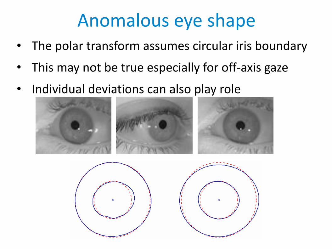
Anomalous eye shape• The polar transform assumes circular iris boundary
• This may not be true especially for off-axis gaze
• Individual deviations can also play role

Feature extraction● Processing the unwrapped image to extract
information
● 2D Gabor wavelet filtering
● Phase quantization
● 2048-bit iris code
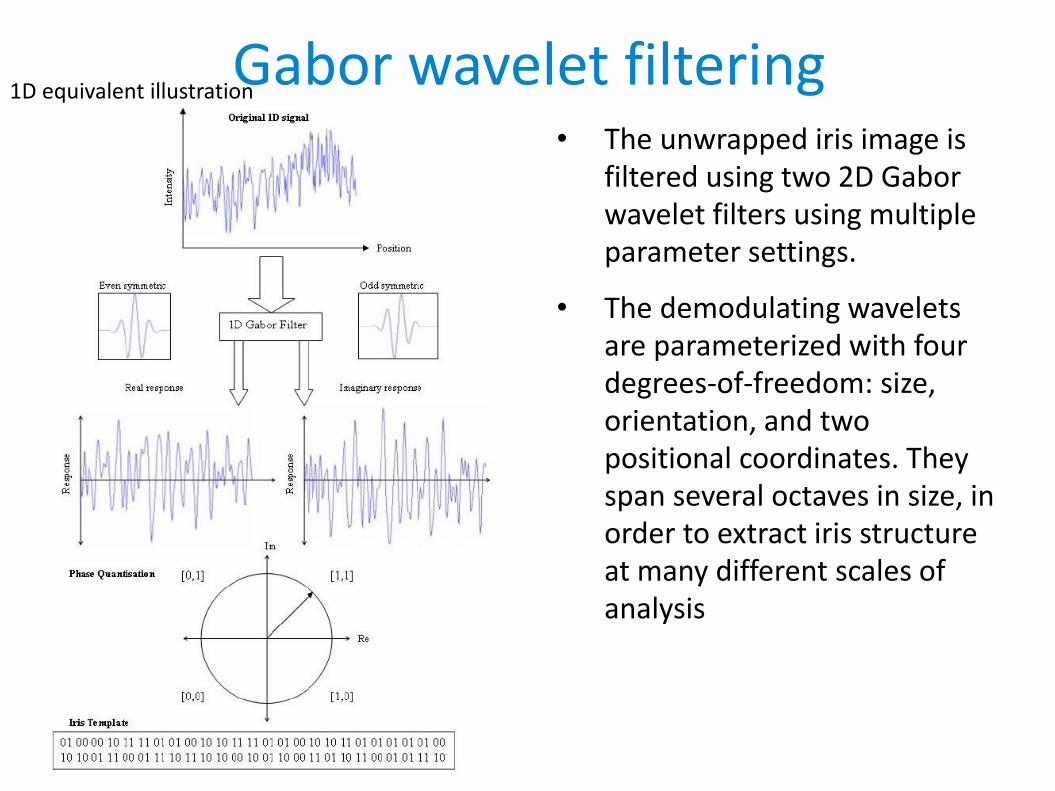
Gabor wavelet filtering• The unwrapped iris image is
filtered using two 2D Gabor wavelet filters using multipleparameter settings.
• The demodulating wavelets are parameterized with four degrees-of-freedom: size, orientation, and two positional coordinates. They span several octaves in size, in order to extract iris structure at many different scales of analysis
1D equivalent illustration

Encoding: Phase quantization• The phase of resulting
complex numbers is observed and coded into 2 bits according to the figure
• Phase quantization -continuous phase to 2 bits
• 2048 such phase bits (256bytes) are computed for each iris.

Masking● Areas with noise (eyelids, eyelashes...) need to be
excluded
● A binary mask of the same size as the iris code is calculated. 1 in the areas of useful signal, 0 elsewhere
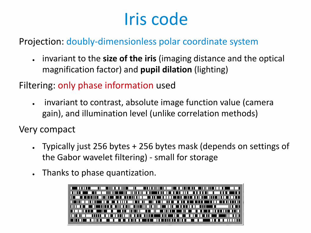
Iris codeProjection: doubly-dimensionless polar coordinate system
● invariant to the size of the iris (imaging distance and the optical magnification factor) and pupil dilation (lighting)
Filtering: only phase information used
● invariant to contrast, absolute image function value (camera gain), and illumination level (unlike correlation methods)
Very compact
● Typically just 256 bytes + 256 bytes mask (depends on settings of the Gabor wavelet filtering) - small for storage
● Thanks to phase quantization.

Example iris codes

Iris code comparison
● Different eyes’ Iris Codes are compared by vector Exclusive-OR’ing in order to detect the fraction of their bits that disagree.
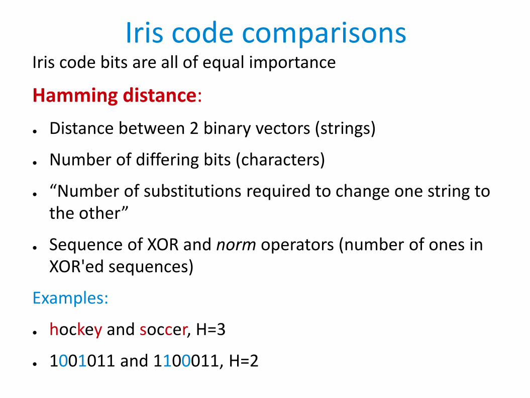
Iris code comparisonsIris code bits are all of equal importance
Hamming distance:
● Distance between 2 binary vectors (strings)
● Number of differing bits (characters)
● “Number of substitutions required to change one string to the other”
● Sequence of XOR and norm operators (number of ones in XOR'ed sequences)
Examples:
● hockey and soccer, H=3
● 1001011 and 1100011, H=2

Code comparison
● - XOR operator - one for each bit that disagrees
● codeA codeB - iris codes,
● - AND - keep only bits unmasked by both masks
● maskA maskB - noise masking templates for respective iris codes
● || - norm operator - calculate number of bits = 1
● Normalized by the number of bits that are available in both codes (denominator)

Iris comparisons
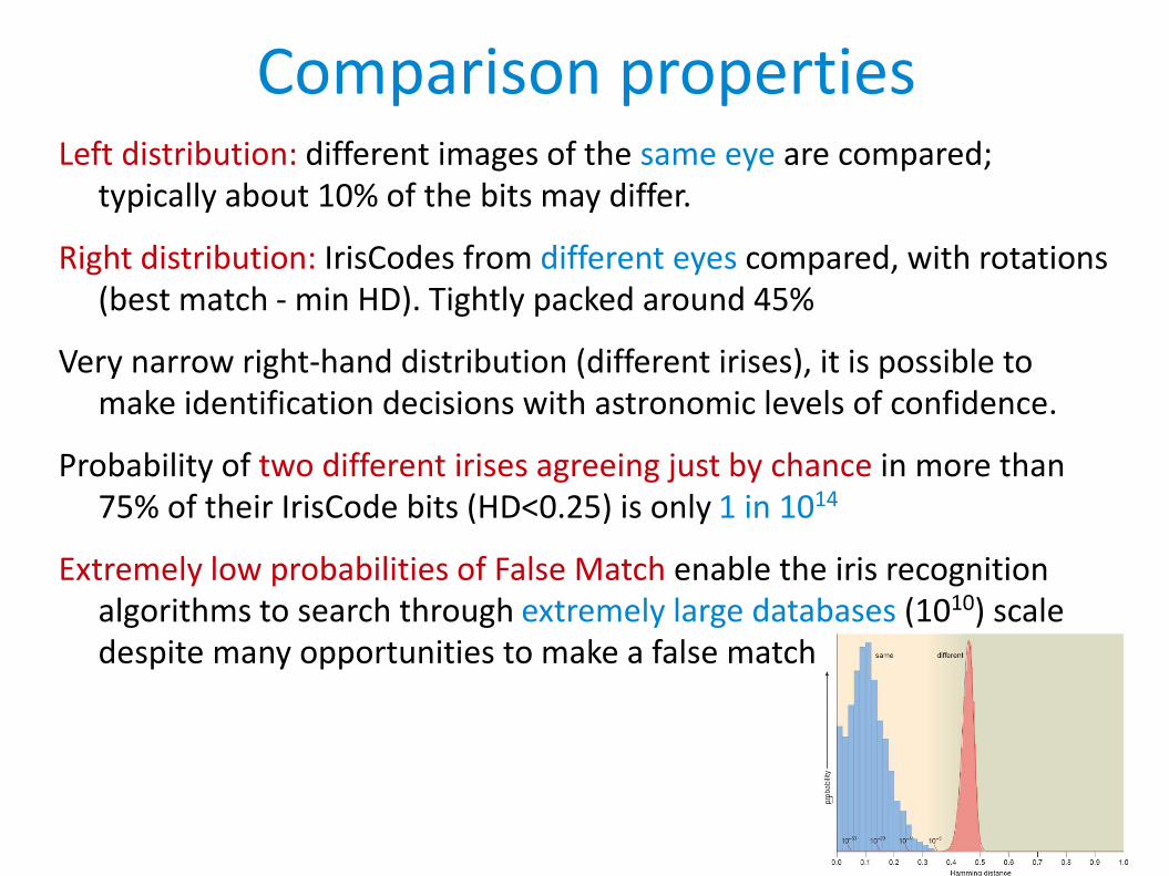
Comparison propertiesLeft distribution: different images of the same eye are compared;
typically about 10% of the bits may differ.
Right distribution: IrisCodes from different eyes compared, with rotations (best match - min HD). Tightly packed around 45%
Very narrow right-hand distribution (different irises), it is possible to make identification decisions with astronomic levels of confidence.
Probability of two different irises agreeing just by chance in more than 75% of their IrisCode bits (HD<0.25) is only 1 in 1014
Extremely low probabilities of False Match enable the iris recognition algorithms to search through extremely large databases (1010) scale despite many opportunities to make a false match
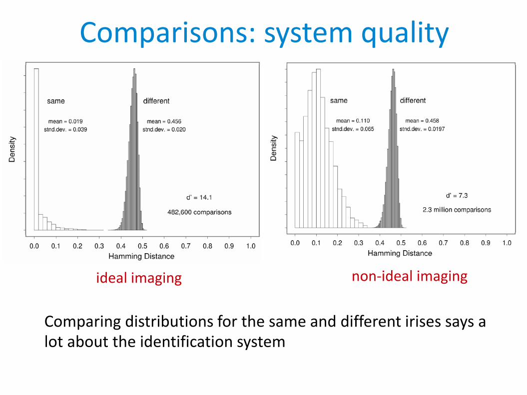
Comparisons: system quality
Comparing distributions for the same and different irises says a lot about the identification system
ideal imaging non-ideal imaging
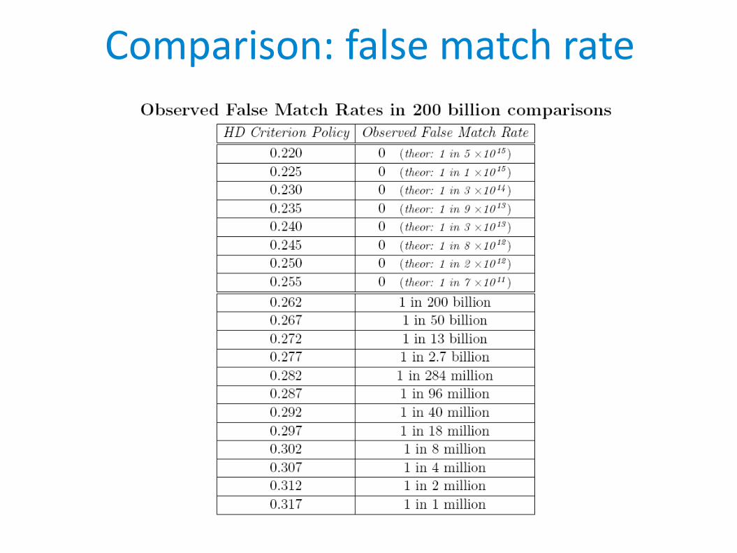
Comparison: false match rate

IrisCode statistics: Bernoulli trials
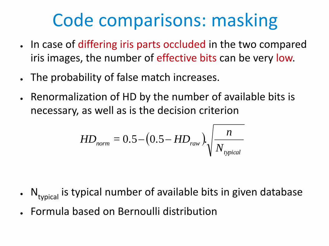
Code comparisons: masking● In case of differing iris parts occluded in the two compared
iris images, the number of effective bits can be very low.
● The probability of false match increases.
● Renormalization of HD by the number of available bits is necessary, as well as is the decision criterion
● Ntypical is typical number of available bits in given database
● Formula based on Bernoulli distribution
typical
rawnormN
nHD=HD .0.50.5
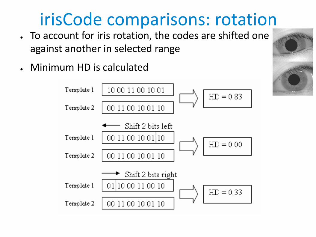
irisCode comparisons: rotation● To account for iris rotation, the codes are shifted one
against another in selected range
● Minimum HD is calculated

irisCode comparison Performance● On a 300MHz PC (long ago):
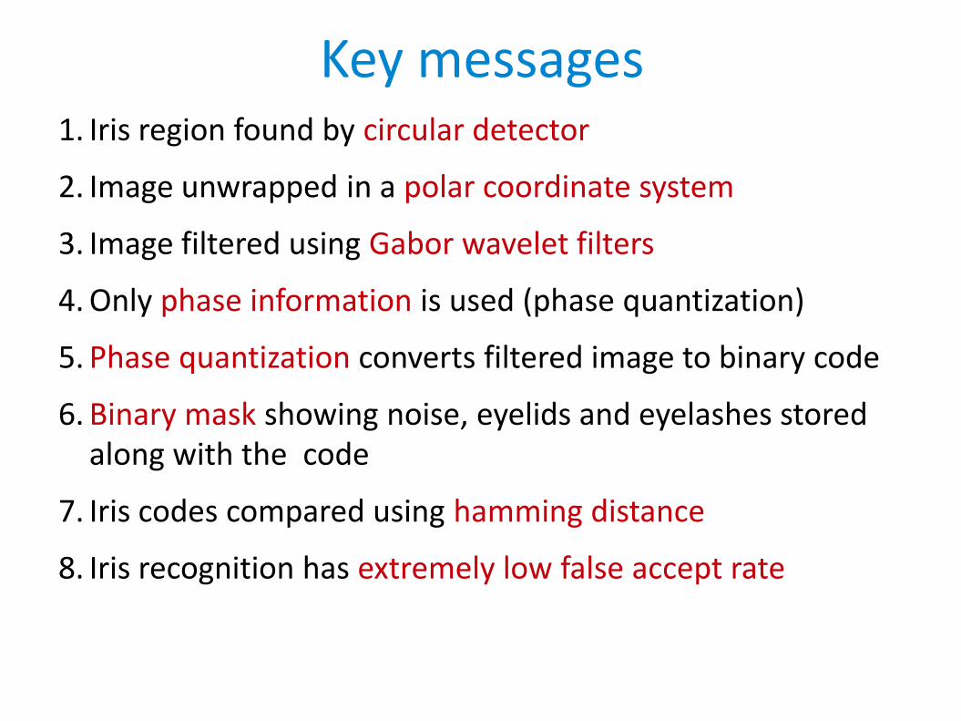
Key messages1. Iris region found by circular detector
2. Image unwrapped in a polar coordinate system
3. Image filtered using Gabor wavelet filters
4. Only phase information is used (phase quantization)
5. Phase quantization converts filtered image to binary code
6. Binary mask showing noise, eyelids and eyelashes stored along with the code
7. Iris codes compared using hamming distance
8. Iris recognition has extremely low false accept rate

Iris recognition summaryStrengths
•It has the potential for exceptionally high levels ofaccuracy
•It is capable of reliableidentification as well as verification
•Believed to be the most reliable metric
•Stability of characteristic over a lifetime
•Distant cameras – less obtrusive
Weaknesses
• Acquisition of the image requiresmoderate training andattentiveness
• It is biased for false rejection (better for identification)
• A proprietary acquisition deviceis necessary for deployment -expensive
• There is some user discomfort with eye-based technology
• Sunglasses, ambient light etc

Thank you for your attention