irc — mechanical - media.iccsafe.orgmedia.iccsafe.org/codes/2018-2019/groupa/cah/irc-m.pdf ·...
TRANSCRIPT
2018 GROUP A PROPOSEDCHANGES TO THE I-CODESCOLUMBUS COMMITTEE ACTIONHEARINGS
April 15–23, 2018Columbus Convention CenterColumbus, Ohio
IRC — Mechanical

First Printing
Publication Date: February 2018
Copyright © 2018 By
International Code Council, Inc.
ALL RIGHTS RESERVED. This 2018-2019 Code Development Cycle, Group A (2018) Proposed Changes to the 2018 International Codes is a copyrighted work owned by the International Code Council, Inc. Without advanced written permission from the copyright owner, no part of this book may be reproduced, distributed, or transmitted in any form or by any means, including, without limitations, electronic, optical or mechanical means (by way of example and not limitation, photocopying, or recording by or in an information storage retrieval system). For information on permission to copy material exceeding fair use, please contact: Publications, 4051 West Flossmoor Road, Country Club Hills, IL 60478 (Phone 1-888-422-7233). Trademarks: “International Code Council,” the “International Code Council” logo are trademarks of the International Code Council, Inc.
PRINTED IN THE U.S.A.

2018 GROUP A – PROPOSED CHANGES TO THE INTERNATIONAL RESIDENTIAL CODE – PLUMBING/
MECHANICAL
PLUMBING/MECHANICAL CODE COMMITTEE W. Travis Lindsey, MCP, Chair Sr. Plans Examiner City of Scottsdale Scottsdale, AZ Marguerite Carroll, Vice Chair Codes and Regulatory Services Manager Underwriters Laboratories Fremont, CA John Ainslie Rep: National Association of Home Builders Owner Ainslie Group Virginia Beach, VA Richard C. Anderson Division Manager/Deputy Building Official City of Austin Austin, TX Roland Asp, CET Manager of Installation Standards National Fire Sprinkler Association Linthicum Heights, MD Pennie Feehan Rep: Copper Development Association Owner Pennie L. Feehan Consulting Palm Springs, CA R. L. Ric Johnson, CAPS, DHTI+ Rep: National Association of Home Builders President/CEO Right at Home Technologies Ada, OH
Nick McAndrew, PE Professional Engineer I (Civil/Construction) NY Department of State Division of Buildings Standards and Codes Albany, NY David W. Perry Sr. Combination Inspector City of Richardson Richardson, TX Thomas Polino Plumbing Subcode Official West Windsor Township West Windsor, NJ Loren K. Swanson, BSIE Rep: National Association of Home Builders Retired from Southern Michigan Co. Jackson, MI Jeremy Wright Rep: National Association of Home Builders President J. Wright Building Company J. Wright Home Design Birmingham, AL Staff Secretariat: Fred Grable, PE Senior Staff Engineer - Plumbing International Code Council Central Regional Office Country Club Hills, IL Gregg Gress Senior Technical Staff International Code Council Central Regional Office 4051 W. Flossmoor Rd Country Club Hills, IL
RM1

TENTATIVE ORDER OF DISCUSSION 2018 PROPOSED CHANGES TO THE
INTERNATIONAL RESIDENTIAL CODE – MECHANICAL The following is the tentative order in which the proposed changes to the code will be discussed at the public hearings. Proposed changes which impact the same subject have been grouped to permit consideration in consecutive changes. Proposed change numbers that are indented are those which are being heard out of numerical order. Indentation does not necessarily indicate that one change is related to another. Proposed changes may be grouped for purposes of discussion at the hearing at the discretion of the chair. Note that some RM code change proposals may not be included on this list, as they are being heard by another committee. RM1-18
P1-18 Part II RB5-18 RM2-18 RM3-18 RM4-18 RM5-18 RM6-18 RM7-18 M86-18 Part II RM8-18 RM9-18 RM10-18 RM11-18 RM12-18 RM13-18 RM14-18 RM15-18 RM16-18 M53-18 Part II RM17-18 RM18-18 RM19-18 RM20-18 RM21-18 RM22-18 RM23-18
RB1-18 RB2-18 RB3-18 RM24-18 RM25-18 RM26-18 RM27-18 RM28-18 RM29-18 RM30-18 RM31-18
M78-18 Part II RM32-18 RM33-18 RM34-18 RM35-18 M119-18 Part II RM36-18 RM37-18 RM38-18 RM39-18 RM40-18 RM41-18 RM42-18 RM43-18 RM44-18 RM45-18 RM46-18
RM2

RM1-18IRC: Chapter 21, 202 (New)Proponent: Mark Fasel, representing Viega LLC ([email protected])
2018 International Residential Code
CHAPTER 21 HYDRONIC PIPING
Add new def inition as follows:
PRESS-CONNECT JOINT A permanent mechanical joint incorporating an elastomeric seal or an elastomeric seal andcorrosion-resistant grip or bite ring. The joint is made with a pressing tool and jaw or ring approved by the fittingmanufacturer.
Reason:Currently the IRC does not include the definition of Press-Connect Joint which is used in the text of the code in IRCsection M2103.3. Including this definition will align the definitions as similarly provided for in the IMC and IPC.Cost ImpactThe code change proposal will not increase or decrease the cost of construction . .This proposed definition will not increase or decrease cost of construction as it defines a pipe joining method alreadyreferenced in the code.Internal ID: 787
RM3

RM2-18IRC: M1305.1.4 (New), M1305.1.4.1 (New), M1305.1.4.2 (New)Proponent: Brent Ursenbach, representing Salt Lake County Planning and Development Services([email protected])
2018 International Residential Code
Add new text as follows:
M1305.1.4 Equipment and appliances on roofs or elevated structures. Where equipment requiring access orappliances are located on an elevated structure or the roof of a building such that personnel will have to climb higherthan 16 feet (4877 mm) above grade to access such equipment or appliances, an interior or exterior means of accessshall be provided. Such access shall not require climbing over obstructions greater than 30 inches (762 mm) in heightor walking on roofs having a slope greater than four units vertical in 12 units horizontal (33-percent slope).Whereaccess involves climbing over parapet walls, the height shall be measured to the top of the parapet wall. Roof accessshall not require the use of portable ladders except where roof access is from the building interior through an atticspace, or through a hatch in the roof assembly, and the height necessary to climb on such portable ladder does notexceed 16 feet. Roof hatches used for access shall comply with the dimension requirements for an attic access.Permanent ladders installed to provide the required access shall comply with the following minimum design criteria:
1. The side railing shall extend above the parapet or roof edge not less than 30 inches (762 mm).2. Ladders shall have rung spacing not to exceed 14 inches (356 mm) on center. The uppermost rung
shall be not greater than 24 inches (610 mm) below the upper edge of the roof hatch, roof orparapet, as applicable.
3. Ladders shall have a toe spacing not less than 6 inches (152 mm) deep.4. There shall be not less than 18 inches (457 mm) between rails.5. Rungs shall have a diameter not less than 0.75-inch (19.1 mm) and be capable of withstanding a
300-pound (136 kg) load.6. Ladders over 30 feet (9144 mm) in height shall be provided with offset sections and landings
capable of withstanding 100 pounds per square foot (488 kg/m ). Landing dimensions shall be notless than 18 inches (457 mm) and not less than the width of the ladder served. A guard rail shall beprovided on all open sides of the landing.
7. Climbing clearance. The distance from the centerline of the rungs to the nearest permanent objecton the climbing side of the ladder shall be not less than 30 inches (762 mm) measuredperpendicular to the rungs. This distance shall be maintained from the point of ladder access to thebottom of the roof hatch. A minimum clear width of 15 inches (381 mm) shall be provided on bothsides of the ladder measured from the midpoint of and parallel with the rungs except where cagesor wells are installed.
8. Landing required. The ladder shall be provided with a clear and unobstructed bottom landing areahaving a minimum dimension of 30 inches (762 mm) by 30 inches (762 mm) centered in front of theladder.
9. Ladders shall be protected against corrosion by approved means.10. Access to ladders shall be provided at all times.
Catwalks installed to provide the required access shall be not less than 24 inches (610 mm) wide and shall haverailings as required for service platforms.
M1305.1.4.1 Sloped roofs. Where appliances, equipment, fans or other components that require service areinstalled on a roof having a slope of three units vertical in 12 units horizontal (25-percent slope) or greater and havingan edge more than 30 inches (762 mm) above grade at such edge, a level platform shall be provided on each side ofthe appliance or equipment to which access is required for service, repair or maintenance. The platform shall be notless than 30 inches (762 mm) in any dimension and shall be provided with guards. The guards shall extend not less than42 inches (1067 mm) above the platform, shall be constructed so as to prevent the passage of a 21-inch-diameter (533mm) sphere and shall comply with the loading requirements for guards specified in this code. Access shall not requirewalking on roofs having a slope greater than four units vertical in 12 units horizontal (33-percent slope). Where accessinvolves obstructions greater than 30 inches (762 mm) in height, such obstructions shall be provided with laddersinstalled in accordance with Section M1305.1.4 or stairways installed in accordance with the requirements specified inthis code in the path of travel to and from appliances, fans or equipment requiring service.
2
RM4

M1305.1.4.2 Electrical requirements. Electrical requirements. A receptacle outlet shall be provided at or nearthe equipment location in accordance with Section E3901.12.
Reason:The IRC and IMC have always included provisions for the safe access to appliances and equipment, for inspection,maintenance, repair and replacement, in rooms, attics and under-floor spaces. The IMC has also included requirementsfor appliances located on roofs or elevated structures, the location where the greatest hazards exist; however, theIRC is silent on access to appliances and equipment on roofs or elevated structures.It's not logical to have a code which protects safety of those servicing commercial HVAC systems located on roofs andignores the safety of those servicing HVAC equipment located roofs of SFD, duplexes and townhouses. Homeownersoften perform annual maintenance on their own HVAC systems. Is their safety less important than the safety of theHVAC technician? This proposal is similar to the requirements from the IMC; however this proposal allows the use of a portable ladder,for use inside the dwelling, for access to the attic or directly on the roof through roof rafters and a roof access.This has become a significant issue in recent years with the trend of building 2 and 3 story townhouses, with RTU's orcondensing units located on the roof. Many of these projects have roof more than 30' above grade. - Cost ImpactThe code change proposal will increase the cost of construction .This proposal will increase the cost of construction only in situations where HVAC systems are installed on roofs orelevated structures higher than 16 feet.Internal ID: 1444
RM5

RM3-18IRC: M1307.7 (New)Proponent: Pennie Feehan, representing Plumbing, Mechanical, and Fuel Gas Code Action Committee([email protected])
2018 International Residential Code
Add new text as follows:
M1307.7 Prohibited support. Gypsum board shall not be used as a support base under an appliance.
Reason:If appliances are installed resting on gypsum board, the board can compress, degrade from heat, moisture andvibration and crumble, with the result being movement and settling of the appliance which would put stress on gaspiping, vent connectors, chimney connectors, electrical connections and ductwork. Gypsum board is not intended to bea support base for vertical deadloads.This proposal is submitted by the ICC Plumbing/Mechanical/Gas Code Action Committee (PMG CAC). The PMG CAC wasestablished by the ICC Board of Directors to pursue opportunities to improve and enhance the International Codes orportions thereof that were under the purview of the PMG CAC. In 2017 the PMG CAC held one face-to-face meeting and11 conference call meetings. Numerous interested parties attended the committee meetings and offered their input.Cost ImpactThe code change proposal will not increase or decrease the cost of construction .This proposal will not increase the cost of construction because no additional labor, materials, equipment, appliancesor devices are mandated beyond what is currently required by the code.Internal ID: 379
RM6

RM4-18IRC: M1308.3 (New)Proponent: Howard Ahern, representing Airex Manufacturing ([email protected])
2018 International Residential Code
Add new text as follows:
M1308.3 Wall Penetration Sealing. Where pipe penetrates a building envelope wall, the annular space betweenthe outside of the pipe and the inside of a pipe sleeve and the annular space between the outside of a pipe sleeveand the opening in a building envelope wall shall be sealed with caulking material or closed with a gasketing system.Caulking materials, and gasketing systems shall allow for expansion and contraction of material and mechanicalvibration, shall be designed for the conditions at the location of the penetration, and shall be compatible with the pipe,sleeve and building materials in contact with the sealing materials. Annular spaces created by pipes penetrating fire-resistance-rated assemblies or membranes of such assemblies shall be sealed or closed in accordance with this code
Reason:There are no sections for sealing wall pipe penetrations for mechanical systems.This change provides for the annular sealing of pipe penetrations for mechanical systems, some mechanical pipingmay vibrate and this change shall allow for the proper sealing of these penetrations.Cost ImpactThe code change proposal will not increase or decrease the cost of construction .Sealing of the pipe wall penetration should be part of standard construction practice,and not lead to increased cost ,however sealing of refrigerant piping should not increase cost , also the IBC requires rodent proofing as well Internal ID: 385
RM7

RM5-18IRC: M1309 (New)Proponent: Craig Conner, representing self ([email protected]); Jani Palmer ([email protected])
2018 International Residential Code
Add new text as follows:
M1309 Radon testing. Radon testing shall be performed for radon zone 1, as defined in Appendix F. This sectionrequires that tests be performed and the results be provided to the owner, but does not require a specific test result..
Exceptions:
1. Testing is not required where the authority having jurisdiction has defined the radon zone asZone 2 or 3.
2. Testing is not required where the occupied space is located above an open space.Testing shall be performed as specified in items 1 through 10:
1. Testing shall be performed after the dwelling passes its air tightness test.2. Testing shall be performed after the radon control system installation is complete. If the system
has an active fan, the residence shall be tested with the fan operating.3. Testing shall be performed at the lowest floor level that will be occupied, whether or not the
space is finished. Spaces that are physically separated and served by different HVAC systemsshall be tested separately.
4. Testing shall not performed in a closet, hallway, stairway, laundry room, furnace room, bathroomor kitchen.
5. Testing shall be performed with a commercially available radon test kit or with a continuousradon monitor that can be calibrated. Testing with test kits shall include two tests, and the testresults shall be averaged. Testing shall be in accordance with the testing device manufacturer'sinstructions.
6. Testing shall be performed by the builder, a registered design professional, or an approved thirdparty.
7. Testing shall be conducted over a period of not less than 48 hours or not less that the periodspecified by the testing device manufacturer, whichever is longer. The initial testing shall beginprior to occupancy, but need not be completed prior to occupancy.
8. Test results shall be provided directly to the owner by the test lab or testing party and shall bedelivered either before or after occupancy.
9. An additional pre-paid test kit shall be provided to the owner to utilize at the owner's discretion.The test kit shall include mailing or emailing the results from the testing lab to the owner.
10. The owner or registered design professional shall be notified in writing prior to occupancy,stating one of the following:10.1. A radon test result of 4 pCi/L or above is the ‘action level' set by EPA. The EPA
recommends radon reduction measures to lower radon levels below 4 pCi/L.".10.2. For a radon test result of 4 pCi/L or above [name of builder or authority having
jurisdiction] recommends radon reduction measures to lower radon levels below 4 pCi/L."
Reason:Radon tests are the only way to know if a residence has significant levels of radon. The test kits are inexpensive andeasy to use. This change is designed not to delay the sale or occupancy of the home. Testing in radon zone 1provides information for areas that tend to have higher levels of radon. Cost ImpactThe code change proposal will increase the cost of construction .Multiple companies make inexpensive radon test kits. This change would require two tests which are averaged, plus athird test kit to be left with the owners. Three tests including pre-paid testing, postage and tax will cost less that $80,often less than $50.
RM8

Internal ID: 2385
RM9

RM6-18IRC: M1305.1.4.4 (New)Proponent: Guy McMann, representing Colorado Association of Plumbing and Mechanical Officials (CAPMO)([email protected]); Troy Jones, representing Jefferson County Division of Building Safety ([email protected])
2018 International Residential Code
Add new text as follows:
M1305.1.4.4 Ladder Required. Where mechanical equipment or appliances that require servicing are located inunder floor spaces that are greater than 30 inches in depth below the floor level, the access openings to such spacesshall be equipped with an approved, permanently affixed ladder capable of withstanding a 300-pound (136.1 kg) load.Such ladders shall be securely fastened to the structure at the top and bottom, shall have a rung spacing of not lessthan 14 inches (356 mm) on center and a rail spacing of not less than 18 inches (457 mm) between rails. Laddersconstructed of dimensional lumber shall be not less than nominal two by four members. Fasteners shall be inaccordance with Table R602.3 (1) item 16 for end nailing or other approved fastening methods.
Reason:The code tells us how to go up but it doesn't tell us how to go down. Ladders constructed of wood in many instanceslack the quality in construction to support the weight imposed on them. Often the rungs break exposing the fastenersthat can seriously wound the person accessing the ladder. There needs to be a ladder capable of withstanding therepeated use that accessing appliances and equipment in crawlers and under floor spaces require. The spacingrequirements are the same as found in the IMC along with the loading requirements. This proposal provides muchflexibility in construction. Guidance for using wood has been provided. Other methods of construction shall be up forapproval by the AHJ.Cost ImpactThe code change proposal will increase the cost of construction .This requirement may increase cost as it has not been required to install a ladder in a under floor access opening todate although many just do it anyway in a haphazard way.Internal ID: 170
RM10

RM7-18IRC: M1401.1Proponent: David Bixby, Air Conditioning Contractors of America (ACCA), representing Air Conditioning Contractors ofAmerica ([email protected])
2018 International Residential Code
M1401.1 Installation. Heating and cooling equipment and appliances shall be installed in accordance with themanufacturer's instructions and the requirements of this code. HVAC systems shall be installed in compliance withACCA 5 QI.
Reason:ACCA 5 QI details nationally-recognized minimum criteria for the proper installation of HVAC systems in new andexisting residential and commercial buildings. This Standard provides a universally accepted definition for qualityinstallation across a broad spectrum of the HVAC industry (e.g., manufacturers, distributors, contractors, user groups,customers, utilities, efficiency advocates, trade associations, professional societies, and governmental agencies). Inthis Standard, the QI elements focus on the application and how well the system is selected and actually installed. ACCA 5 QI is also a consensus-based ANSI standard. A proposal to add ACCA 5 QI to Chapter 44, ReferencedStandards, has also been submitted. Cost ImpactThe code change proposal will not increase or decrease the cost of construction .Cost impacts for using ACCA 5 QI would be minimal, other than some extra time involved. Installers will have toperform calculations for ventilation, heat loss/gain, ensure proper equipment sizing and selection, in order to comply. This is a guide for making sure the industry performs quality installations based on current industry practice. Codeofficials will have to verify and document compliance.
Analysis: A review of the standard proposed for inclusion in the code, with regard to the ICC criteria for referencedstandards (Section 3.6 of CP#28) will be posted on the ICC website on or before April 2, 2018.Internal ID: 1873
RM11
RM8-18IRC: M1404.1Proponent: Jim Tidwell, representing Honeywell ([email protected])
2018 International Residential Code
Revise as follows:
M1404.1 Compliance. Refrigeration cooling equipment shall comply with Section M1411 and ANSI/ASHRAE 15.
Reason:ASHRAE 15 is the accepted standard for the installation of refrigeration equipment, and should be referenced by theIRC. We believe this was an oversight, and this change corrects that oversight. The IMC references this standard aswell. Cost ImpactThe code change proposal will not increase or decrease the cost of construction .The code change may change the cost of construction, either by increasing it or decreasing it depending upon thesystem being installed. Referencing a national standard for installation criteria should streamline the overall process. Internal ID: 2258
RM12

RM9-18IRC: M1411.3.1.2 (New)Proponent: Guy McMann, Jefferson County Colorado, representing Colorado Association of Plumbing and MechanicalOfficials (CAPMO) ([email protected])
2018 International Residential Code
Add new text as follows:
M1411.3.1.2 Appliance, equipment and insulation in pans. Where appliances, equipment or insulation aresubject to water damage when auxiliary drain pans fill, that portion of the appliance, equipment and insulation shall beinstalled above the rim of the pan. Supports located inside of the pan to support the appliance or equipment shall bewater resistant and approved.
Reason:This is editorial in nature and is missing from this code. This can be found in the IMC Section 307.2.3.2 and in the IPC.This addition will make the IRC consistant with the other codes.Cost ImpactThe code change proposal will not increase or decrease the cost of construction .This change is editorial in nature.Internal ID: 152
RM13

RM10-18IRC: M1411.6Proponent: Pennie Feehan, representing Plumbing, Mechanical, and Fuel Gas Code Action Committee([email protected])
2018 International Residential Code
Revise as follows:
M1411.6 Insulation of ref rigerant piping. Piping and fittings for refrigerant vapor (suction) lines shall beinsulated with insulation having a thermal resistivity of not less than R-4 3 and having external surface permeance notexceeding 0.05 perm [2.87 ng/(s • m • Pa)] when tested in accordance with ASTM E96.
Reason:This change is simply for consistency with the Chapter 11 energy provisions. The two insulation requirements did notmatch and caused confusion.This proposal is submitted by the ICC Plumbing/Mechanical/Gas Code Action Committee (PMG CAC). The PMG CAC wasestablished by the ICC Board of Directors to pursue opportunities to improve and enhance the International Codes orportions thereof that were under the purview of the PMG CAC. In 2017 the PMG CAC held one face-to-face meeting and11 conference call meetings. Numerous interested parties attended the committee meetings and offered their input.Cost ImpactThe code change proposal will not increase or decrease the cost of construction .This proposal will not increase the cost of construction because no additional labor, materials, equipment, appliancesor devices are mandated beyond what is currently required by the code.Internal ID: 484
2
RM14

RM11-18IRC: M1411.8 (New)Proponent: Howard Ahern, Airex Manufacturing, representing Airex Manufacturing ([email protected])
2018 International Residential Code
Add new text as follows:
M1411.8 Support of Refrigerant piping. Refrigerant piping & tubing shall be securely fastened to a permanentsupport within 6 feet of the compressor and within 3 feet of each subsequent bend or angle.
Reason:This proposal will require support of the Refrigerant piping which vibrates and that can lead to damage of piping andjoints from vibration and stress. Unfortunately many refrigerant pipes are not supported from the condenser, or theonly support is foam , caulking in the walls penetration. This proposal will require supporting of the piping to ensuresafety, reduce piping ,and joints damage from vibration and stress. Bibliography:Howard Ahernrepresenting Airex ManufacturingNational Sales and Technical ManagerCost ImpactThe code change proposal will decrease the cost of construction .The piping should already be supported .Internal ID: 2362
RM15
RM12-18IRC: M1503.3Proponent: Mike Moore, Newport Ventures, representing Broan-NuTone ([email protected])
2018 International Residential Code
M1503.3 Exhaust discharge. Domestic cooking exhaust equipment shall discharge to the outdoors through a duct.The duct shall have a smooth interior surface, shall be air tight, shall be equipped with a backdraft damper and shall beindependent of all other exhaust systems. Ducts serving domestic cooking exhaust equipment shall not terminate in anattic or crawl space or areas inside the building.Listed and labeled ductless range hoods shall not be required to discharge to the outdoors where all of the followingconditions are met:
Exception: Where installed in accordance with the manufacturer’s instructions, and where mechanical or naturalventilation is otherwise provided, listed and labeled ductless range hoods shall not be required to discharge to theoutdoors.
1. The equipment is installed in accordance with the manufacturer's instructions.2. Mechanical or natural ventilation is otherwise provided in the cooking area.3. The equipment is installed in a newly constructed dwelling unit other than single family, or is
installed in an existing kitchen not having an existing range hood exhaust duct to the outdoors.
Reason:Cooking is typically the largest source of indoor air pollution in homes, with concentrations of key pollutants frequentlyexceeding U.S. National Ambient Air Quality Standards. Over time, exposure to these pollutants has been shown toreduce length and quality of life. Clearly, kitchen ventilation is needed to comply with the purpose of the IRC to“safeguard public safety, health, and general welfare through…ventilation” (among other means). Unless captured andexhausted at the source, cooking pollutants spread rapidly through a home and deposit themselves on surfaces, onlyto be released again into the breathing zone when disturbed at a later time. For new construction in detachedbuildings, where the builder elects to install a range hood, requiring that the range hood be ducted is a very low-costitem with high returns in terms of occupant health. For reasons of constructability and cost sensitivity (not health), thisproposal would only permit ductless range hoods when they are installed in an attached dwelling unit of newconstruction or when they are installed in an existing kitchen that doesn’t have an pre-existing range hood exhaustduct.Bibliography:Wallace, L. A., Emmerich, S. J., & Howard-Reed, C. (2004). Source strengths of ultrafine and fine particles due to cookingwith a gas stove. Environmental Science & Technology, 38(8), 2304-2311.Singer, B. C., Apte, M. G., Black, D. R., Hotchi, T., Lucas, D., Lunden, M.,Sullivan, D. P. (2010). Natural Gas Variability inCalifornia: Environmental Impacts and Device Performance: Experimental Evaluation of Pollutant Emissions fromResidential Appliances. Sacramento CA: California Energy Commission.Dennekamp, M., Howarth, S., Dick, C. A. J., Cherrie, J. W., Donaldson, K., & Seaton, A. (2001). Ultrafine particles andnitrogen oxides generated by gas and electric cooking. Occupational and Environmental Medicine, 58(8), 511-516.Moschandreas, D. J., & Relwani, S. M. (1989). Field-Measurements of NO2 Gas Range-Top Burner Emission Rates.Environment International, 15(1-6), 489-492.Moschandreas, D., Relwani, S., Johnson, D., & Billick, I. (1986). Emission Rates from Unvented Gas Appliances.Environment International, 12(1-4), 247-254.EPA. Fine Particle Designations. Available at http://www.epa.gov/pmdesignations/faq.htm. Sourced on December 10,2014.Logue et al. (2012). A method to estimate the chronic health impact of air pollutants in U.S. residences. EnvironmentalHealth Perspectives: 120(2): 216–222.McKenna, M.T., C.M. Michaud, C.J.L. Murray, and J.S. Marks. (2005). Assessing the burden of disease in the United Statesusing disability-adjusted life years. Am J Prev Med.: 28(5):415–423.Nicole, W. (2014). Cooking Up Indoor Air Pollution: Emissions from Natural Gas Stoves. Environ Health Perspect: 122-A27.Offerman, F.J. (2009). Ventilation and indoor air quality in new homes. PIER Collaborative Report. California EnergyCommission & California Environmental Protection Agency Air Resources Board.Klug, V. L., Lobscheid, A. B., & Singer, B. C. (2011). Cooking Appliance Use in California Homes – Data Collected from aWeb-Based Survey LBNL-5028E. Berkeley, CA: Lawrence Berkeley National Laboratory.Logue et al. (2014). Pollutant exposures from natural gas cooking burners: a simulation based assessment for SouthernCalifornia.” Lawrence Berkeley National Laboratory. LBNL-6712E.Smith, P.A. (2013). The Kitchen as a Pollution Hazard. New York Times. http://well.blogs.nytimes.com/2013/07/22/the-
RM16

kitchen-as-a-pollution-hazard/?_r=0. Accessed December 10, 2014.Belanger, K., Gent, J. F., Triche, E. W., Bracken, M. B., & Leaderer, B. P. (2006). Association of indoor nitrogen dioxideexposure with respiratory symptoms in children with asthma. American Journal of Respiratory and Critical CareMedicine, 173(3), 297-303. doi: 10.1164/rccm.200408-1123OC.Hansel, N. N., Breysse, P. N., McCormack, M. C., Matsui, E. C., Curtin-Brosnan, J., Williams, D. L., . . . Diette, G. B. (2008). Alongitudinal study of indoor nitrogen dioxide levels and respiratory symptoms in inner-city children with asthma.Environmental Health Perspectives, 116(10), 1428-1432. doi:10.1289/ehp.11349.Garrett, M. H., Hooper, M. A., Hooper, B. M., & Abramson, M. J. (1998). Respiratory symptoms in children and indoorexposure to nitrogen dioxide and gas stoves. American Journal of Respiratory and Critical Care Medicine, 158(3), 891-895.Abdullahi, K. L., Delgado-Saborit, J. M., & Harrison, R. M. (2013). Emissions and indoor concentrations of particulatematter and its specific chemical components from cooking: A review. Atmospheric Environment, 71, 260-294. doi: Doi10.1016/J.Atmosenv.2013.01.061.Buonanno, G., Morawska, L., & Stabile, L. (2009). Particle emission factors during cooking activities. AtmosphericEnvironment, 43(20), 3235-3242. doi: Doi 10.1016/J.Atmosenv.2009.03.044.Fortmann, R., Kariher, P., & Clayton, R. (2001). Indoor air quality: residential cooking exposures. Sacramento, CA:Prepared for California Air Resources Board.Seaman, V. Y., Bennett, D. H., & Cahill, T. M. (2009). Indoor acrolein emission and decay rates resulting from domesticcooking events. Atmospheric Environment, 43(39), 6199-6204. doi: 10.1016/j.atmosenv.2009.08.043.Zhang, Q. F., Gangupomu, R. H., Ramirez, D., & Zhu, Y. F. (2010). Measurement of Ultrafine Particles and Other AirPollutants Emitted by Cooking Activities. International Journal of Environmental Research and Public Health, 7(4), 1744-1759. doi: 10.3390/ijerph7041744.Cost ImpactThe code change proposal will increase the cost of construction .Where builders are already installing ducts with range hoods, there will not be any increase in the cost of construction.Where new, single-family dwelling units are not currently provided with ducts for their range hoods, this proposal wouldincrease the cost of construction. Installed duct costs can be estimated at ~ $9.85 per linear foot for 3.25"x10"galvanized sheet metal (RS Means, 2015, Section 23 31 13.13.0500), and a damper would cost about $15 retail. Internal ID: 1744
RM17

RM13-18IRC: M1502.3Proponent: Pennie Feehan, representing Plumbing, Mechanical, and Fuel Gas Code Action Committee([email protected])
2018 International Residential Code
Revise as follows:
M1502.3 Duct termination. Exhaust ducts shall terminate on the outside of the building. Exhaust duct terminationsshall be in accordance with the dryer manufacturer's installation instructions. If the manufacturer's instructions do notspecify a termination location, the exhaust duct shall terminate not less than 3 feet (914 mm) in any direction fromopenings into buildings including openings in ventilated soffits. Exhaust duct terminations shall be equipped with abackdraft damper. Screens shall not be installed at the duct termination.
Reason:The code does not address ventilated soffits as building openings, which indeed they are.This proposal is submitted by the ICC Plumbing/Mechanical/Gas Code Action Committee (PMG CAC). The PMG CAC wasestablished by the ICC Board of Directors to pursue opportunities to improve and enhance the International Codes orportions thereof that were under the purview of the PMG CAC. In 2017 the PMG CAC held one face-to-face meeting and11 conference call meetings. Numerous interested parties attended the committee meetings and offered their input.Cost ImpactThe code change proposal will not increase or decrease the cost of construction .This proposal will not increase the cost of construction because no additional labor, materials, equipment, appliancesor devices are mandated beyond what is currently required by the code.Internal ID: 529
RM18

RM14-18IRC: 1502.3.2 (New)Proponent: Rick Harpenau, representing self ([email protected])
2018 International Residential Code
Add new text as follows:
1502.3.2 Animal Grills. Where grilles are provided on dryer exhaust duct terminals to prevent entry of animals, thegrille shall consist entirely of vertical slots without horizontal or diagonal members, the slots shall have a width of notless than 5/8 inch, and the total open area of the grille shall be not less than 4 times the opening area of the exhaustduct.
Reason:Rural areas across our country experience sufficient intrusion of squirrels, rodents and birds. So much so thathomeowners seek or create their own protection. Many resort to mechanical cloth wraps with wire spacing of lessthan ½”. Plastic grills are common as well but due to the lack of material strength, the grill partitions are large and flatpromoting accelerated lint build up. Some plastic wall vent hoods incorporate an integral defensive grill. Generally, thisdesign does not provide an adequate area spread and aperture size of each opening is insufficient to allow the lintaccumulation to release and exit. Currently Section 1502.3 clearly indicates screens shall not be installed at the duct termination. Grills and screenscould be considered equivalent in description causing confusion. A separate section defining acceptable grills seemslogical and removes the equal comparison argument for grills and screens and their use at or near the dryertermination. Vertical bars resist accelerated lint build up. The text simply lays out criteria for cages to feature vertical bars.
RM19

RM20

RM21

RM22

Bibliography:Inventor of the Dryerbox. Owner of In-O-Vate Technologies Inc.Cost ImpactThe code change proposal will not increase or decrease the cost of construction .A rodent/bird defensive grill or cage is an owner/occupant discretionary item.Wording is necessary to distinguish grills from disallowed screens. Internal ID: 426
RM23

RM15-18IRC: M1502.4.2Proponent: Rick Harpenau, representing self ([email protected])
2018 International Residential Code
Revise as follows:
M1502.4.2 Duct installation. Exhaust ducts shall be supported at intervals not to exceed 12 4 feet (3658 1219 mm)and shall be secured in place. The insert end of the duct shall extend into the adjoining duct or fitting in the direction ofairflow. Exhaust duct joints shall be sealed in accordance with Section M1601.4.1 and shall be mechanically fastened.Ducts shall not be joined with screws or similar fasteners that protrude more than / inch (3.2 mm) into the inside ofthe duct. Where dryer exhaust ducts are enclosed in wall or ceiling cavities, such cavities shall allow the installation ofthe duct without deformation.
Reason:12 feet spacing does not provide adequate support for sections of pipe that feature a maximum length of 5 feet. Also,for consistency, the Mechanical Code requires 4 feet support intervals. For the most part, the Res and Mech codesmirror themselves except for the support intervals. These images show the importance of both mechanical fastening,seam taping and 4 foot interval support spacing.
Bibliography:Inventor of the Dryerbox receptacle, president of In-O-Vate Technologies IncCost ImpactThe code change proposal will not increase or decrease the cost of construction .Clarification and consistency between the Res and Mech codes. Internal ID: 323
1 8
RM24

RM16-18IRC: M1502.4.2Proponent: Pennie Feehan, representing Plumbing, Mechanical, and Fuel Gas Code Action Committee([email protected])
2018 International Residential Code
Revise as follows:
M1502.4.2 Duct installation. Exhaust ducts shall be supported at intervals not to exceed 12 4 feet (3658 mm) andshall be secured in place. The insert end of the duct shall extend into the adjoining duct or fitting in the direction ofairflow. Exhaust duct joints shall be sealed in accordance with Section M1601.4.1 and shall be mechanically fastened.Ducts shall not be joined with screws or similar fasteners that protrude more than / inch (3.2 mm) into the inside ofthe duct. Where dryer exhaust ducts are enclosed in wall or ceiling cavities, such cavities shall allow the installation ofthe duct without deformation.
Reason:This proposal will correlate the IRC provision with that of the IMC. 12 foot spacing is not allowed in the IMC and couldcause light gage ducts to fail during duct cleaning operations. A 12 foot run of dryer exhaust duct would have one ormore joints in it, thus compromising duct integrity where supports are at 12 foot intervals.This proposal is submitted by the ICC Plumbing/Mechanical/Gas Code Action Committee (PMG CAC). The PMG CAC wasestablished by the ICC Board of Directors to pursue opportunities to improve and enhance the International Codes orportions thereof that were under the purview of the PMG CAC. In 2017 the PMG CAC held one face-to-face meeting and11 conference call meetings. Numerous interested parties attended the committee meetings and offered their input.Cost ImpactThe code change proposal will increase the cost of construction .Additional hangars/supports will be required based on shorter intervals.Internal ID: 482
1 8
RM25

RM17-18IRC: M1504.3Proponent: Mike Moore, representing The Home Ventilating Institute ([email protected])
2018 International Residential Code
Revise as follows:
M1504.3 Exhaust openings. Air exhaust openings shall terminate as follows:
1. Not less than 3 feet (914 mm) from property lines.2. Not less than 3 feet (914 mm) from gravity air intake openings, operable windows and doors.3. Not less than 10 feet (3048 mm) from mechanical air intake openings except where either of the
following apply:3.1. The exhaust opening is located not less than 3 feet (914 mm) above the air intake opening.3.2. The exhaust opening is part of a factory-built intake/exhaust combination termination fitting
installed in accordance with the manufacturer's instructions, and the exhaust air is drawnfrom a living space.
4. Openings shall comply with Sections R303.5.2 and R303.6.
Reason:This proposal is very similar to a PMGCAC proposal on the same subject. The only difference is that this proposal doesnot include the word "approved" in front of "factory-built intake/exhaust termination combination fitting". In somejurisdiction, equipment or products requiring approval will trigger an "alternative means and methods" process tosecure a permit. As explained in the reason statement below, these products have been determined to perform wellacross manufacturers and models. With good performance and insignificant deviation across products, there is noneed to further scrutinize these products or delay permits for dwelling units that specify them. This is the position ofthe Home Ventilating Institute.The rest of the reason statement echoes that in the PMGCAC proposal:Intake/exhaust combination terminations are regularly installed with heating and energy recovery ventilators (H/ERVs)used for dwelling units. Their use reduces building penetrations, labor, and associated system costs. By reducing thenumber of penetrations, air leakage can also be reduced, resulting in space conditioning energy savings. Further, thedurability of the structure can be improved through reducing entry pathways for bulk water.Manufacturer tests conducted by Natural Resources Canada (NRC) have demonstrated that use of intake/exhaustcombination terminations results in minimum cross-contamination of airflows (i.e., not exceeding 4%; see NRC reportA1-007793 ). These results are aligned with ASHRAE 62.2 approval of such devices which limits cross-contamination to10%, as verified by the manufacturer. If approved, this proposed modification to the IRC would limit application ofintake/exhaust combination terminations to “approved”, “factory-built” units. Approval of this proposed modification isexpected to result in more affordable and architecturally-flexible terminations.Note: The IRC defines living space as, “space within a dwelling unit utilized for living, sleeping, eating, cooking, bathing,washing and sanitation purposes”. The use of the term “environmental air” was also considered, but was abandonedbecause “environmental air” can also include exhaust air from parking garages and clothes dryers, which we want toexclude from this exception.Bibliography:Bibliography:Ouazia, B. 2016. Evaluation of a dual hood performance in term of contaminant re-entrainment from exhaust to supply.A1-007793. National Research Council Canada. For a copy of the report, please contact the proponent at the emailaddress provided. Additional reports are available from the proponent upon request.Cost ImpactThe code change proposal will decrease the cost of construction .This proposal can reduce the number of intake and exhaust penetrations required for a dwelling unit, thereby reducingthe cost of construction.Internal ID: 1899
1
RM26

RM18-18IRC: M1505.4.1Proponent: Joseph Hill, representing New York State Department of State, Division of Building Standards and Codes([email protected])
2018 International Residential Code
Revise as follows:
M1505.4.1 System design. The whole-house ventilation system shall consist of one or more supply or exhaust fans,or a combination of such, and associated ducts and controls. Local exhaust or supply fans are permitted to serve as apart of such a system. Outdoor air ducts connected to the return side of an air handler shall be considered asproviding supply ventilation. Where building infiltration provides all or a portion of the outdoor air intake for whole-house ventilation, such air intake shall be demonstrated by calculations, otherwise, the whole-house ventilation systemshall be designed to provide outdoor air intake by means other than building infiltration.
Reason:The use of exhaust only ventilation has been the subject of intense debate in the industry, whether exhaust onlyventilation can effectively exchange indoor air with outdoor air as is the defined purpose of a Whole House MechanicalVentilation System. In the case of supply air supplied by building infiltration only, it is hard to justify supply air providedby means of building infiltration only, especially at the rates of infiltration which single family dwellings are required tobe tested. When a single-family residence is tested at less than 5 Air Changes per hour, at ACH 50, Code SectionR303.4 indicates that Mechanical ventilation is required. All climate design zones throughout the United States arerequired to be tested at 5 or less air changes per hour. It is the learned opinion of many in the building science industrythat exhaust only ventilation does not work to provide the fresh air required by code, and additionally, may be thecause of increasing indoor contaminants, rather than alleviating them.This science is not very complex,by adding an exhaust fan any given dwelling , you effectively decrease the internalpressure. This will cause an increase in infiltration, drawing with it any contaminants held within the building envelope,as well as a very likely increase radon. The following reasoning may illustrate this point and rationalize the need for thismodification. The following quotation are in support this statement;From Green Builder magazine (September 2009): “Because exhaust-only ventilation pulls air through the buildingenvelope, this approach can bring contaminants from the garage, dust from attics, pesticides from the outdoors, moldspores, and even radon into the house.”From NSERDA’s “Homeowner’s Guide to Ventilation”: “Exhaust-only ventilation is a good choice for homes that do nothave existing ductwork to distribute heated or cooled air. However, if there is radon in the soil around the house, thismethod can increase indoor radon levels.From Chapter 9 of the Alaska Residential Building Manual: “Exhaust-only ventilation systems, because theydepressurize the house, may increase the amount of radon that enters the living space.”Section M1507 Mechanical Ventilation was introduced into the 2012 IRC, being a derivation of the requirements ofASHRAE 62.2 -2004 Ventilation and Acceptable Indoor Air Quality In Residential Buildings. There are additionalprovisions of ASHRAE 62.2 which require the determination of infiltration air, thereby allowing (not requiring) a portionof the supply air for the mechanical ventilation systems to be provided by building infiltration. There is no allowancethat can be found within 62.2 which allows for 100% of the supply air for mechanical ventilation systems to be providedby building infiltration. The following calculations are present within ASHRAE 62.2 -2016 which require the determinationfor the allowable amount of building infiltration air which can be utilized by the mechanical ventilation system.Section 4.1.2 Infiltration Credit states that if a blower door test has been performed, then a credit for estimatedinfiltration may be taken for non-attached dwelling units using the procedure in Section 4.1.2 (a) 4.1.2 (a) Effective Annual Average Infiltration Rate (O inf) shall be calculated using the normalized leakage calculatedfrom measurements of envelope leakage using either ASTM E779, or CGSB 149.10. The authority having jurisdiction mayapprove other means of calculating effective leakage area (ELA) , such as RESNET Mortgage Industry National; HomeEnergy Systems Standard.The procedure described by 62.2-2016 is represented by Equation 4.2 which states;
ELA= (Lpress+Ldepress)/2 The reference, or test pressure = 4 Pa Where ELA = effective leakage area, ft2
1
1
1
2
2
2
RM27
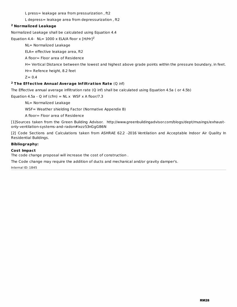
L press= leakage area from pressurization , ft2 L depress= leakage area from depressurization , ft2
Normalized LeakageNormalized Leakage shall be calculated using Equation 4.4Equation 4.4- NL= 1000 x ELA/A floor x [H/Hr] NL= Normalized Leakage ELA= effective leakage area, ft2 A floor= Floor area of Residence H= Vertical Distance between the lowest and highest above grade points within the pressure boundary, in feet. Hr= Refence height, 8.2 feet Z= 0.4
The Ef fective Annual Average Inf iltration Rate (Q inf)The Effective annual average infiltration rate (Q inf) shall be calculated using Equation 4.5a ( or 4.5b)Equation 4.5a - Q inf (cfm) = NL x WSF x A floor/7.3 NL= Normalized Leakage WSF= Weather shielding Factor (Normative Appendix B) A floor= Floor area of Residence[1]Sources taken from the Green Building Advisor. http://www.greenbuildingadvisor.com/blogs/dept/musings/exhaust-only-ventilation-systems-and-radon#ixzz53nGgGB6N [2] Code Sections and Calculations taken from ASHRAE 62.2 -2016 Ventilation and Acceptable Indoor Air Quality InResidential Buildings.Bibliography:Cost ImpactThe code change proposal will increase the cost of construction .The Code change may require the addition of ducts and mechanical and/or gravity damper's.Internal ID: 1845
2
Z
2
RM28

RM19-18IRC: M1505.4.4Proponent: Anthony Floyd, City of Scottsdale, representing City of Scottsdale ([email protected])
2018 International Residential Code
Revise as follows:
M1505.4.4 Local exhaust rates. Local exhaust systems shall be designed to have the capacity to exhaust theminimum airflow rate determined in accordance with Table M1505.4.4. Intermittently operated exhaust fans inbathrooms and toilet rooms shall be provided with a delay-shutoff timer or humidity sensor control.
Exception: A delay-shutoff timer or humidity sensor control switch is not required for exhaust fans that function asa component of a programmed whole-house ventilation system.
Reason:This code change provides compliance options for intermittently operated exhaust fans when the bathroom is occupied(manual or humidity sensor activation) and for a limited period of time after the user leaves the room (delay timer orhumidity sensor deactivation). Delay timer and humidity sensor exhaust fan controls are a consistent and effectivemeans of removing indoor moisture and pollutants.During a bath or shower, the humidity level in a bathroom can be a perfect breeding ground for mold, mildew andmicroorganisms that can negatively impact occupant health. Excess moisture has tremendous potential for damagingthe structure. It cracks and peels paint, ruins gypsum wallboard, causes exterior paint failure, warps doors and rustscabinets and fixtures. It can cause deterioration of joists and framing. As it condenses on windows, walls, ceilings andcabinets, it attracts dirt. It encourages mildew on tile grout and generally provides an environment for increasedbacterial growth.According to the Home Ventilation Institute, an intermittently operated exhaust fan needs to run at least 20 minutesafter each shower to sufficiently remove moisture from an average size bathroom. Bathroom exhaust systems reducethe risk of mildew and mold growth, which is a sanitation and durability concern in all homes, regardless of climate.Delay timer and moisture sensor controlled exhaust fans are more effective than a manually operated fan or anoperable window that is usually left closed during the winter and summer months of the year.Automatic shut-off controls help to ensure exhaust fan operates when the bathroom is in use and for a limited period oftime after the user leaves the room. Automatic controls also save energy by ensuring fans don’t run unnecessarilyafter removal of moisture and pollutants.Bibliography:ASHRAE 62.2-2016 Ventilation and Acceptable Indoor Air Quality in Low-Rise Residential BuildingsHome Ventilating Institute - http://www.hvi.org/publications/HowMuchVent.cfmCost ImpactThe code change proposal will increase the cost of construction .A basic dial delay timer switch costs $15, while a basic humidity sensor switch costs $46. Timer and moisturecontrolled exhaust fans reduce the potential of making costly moisture damage repairs to correct problems that iseasy to avoid with adequate local exhaust.Internal ID: 550
RM29

RM20-18IRC: SECTION M1505, 1505.5 (New)Proponent: Craig Conner, representing self ([email protected])
2018 International Residential Code
SECTION M1505 MECHANICAL VENTILATION
Add new text as follows:
1505.5 Combustion venting into conditioned space. Permanently installed combustion devices that aredesigned to vent combustion products into conditioned space shall be approved by a licensed design professional.
Exception: Section 1505.5 shall not apply to stoves, ovens and pilot lights.
Reason:Combustion devices which are designed to vent combustion products into the conditioned space are high risk from theperspective of indoor air quality. These devices also increase interior moisture and can add contaminants such as NOx(nitrous oxides).Cost ImpactThe code change proposal will increase the cost of construction .There will likely be a cost associated with the review by a licensed design professional. However, it is also possiblethat the design professional will be less expensive than correcting any problem resulting from routinely ventingcombustion products into conditioned space.Internal ID: 2010
RM30

(Equation 15-1)
RM21-18IRC: M1505.4.3Proponent: Craig Conner, representing self ([email protected]); Joseph Lstiburek, representing Self([email protected])
2018 International Residential Code
Revise as follows:
M1505.4.3 Mechanical ventilation rate. The whole house mechanical ventilation system shall provide be capableof providing outdoor air at a minimum continuous rate as determined in accordance with Table M1505.4.3(1) or Equation15-1.Ventilation rate in cubic feet per minute =0.01 × total square foot area of house + 7.5×number of bedrooms + 1
Exception: The whole-house mechanical ventilation system is permitted to operate intermittently where thesystem has controls that enable operation for not less than 25 percent of each 4-hour segment and the ventilationrate prescribed in Table M1505.4.3(1) or in accordance with Equation 15-1 is multiplied by the factor determined inaccordance with Table M1505.4.3(2).
Reason:This code change contains a number of improvements that clarify the intent and requirements of whole-housemechanical ventilation rates.First, the ventilation system must “be capable of providing” the necessary ventilation air. A “manual override” (on/offswitch) must be provided as defined in M1505.4.2. So, as written, if the system is switched off, the house would be outof code compliance.Second, the ventilation rates are minimum values and it should be clearly stated in the code.Third, the term “total square foot area of house” is not a defined term and could easily be interpreted to includeunconditioned spaces (e.g. basements, garages, enclosed porches). "conditioned floor area" is a defined term and isappropriate for determining ventilation rates.Last, Exception 1 intermittent ventilation rates should be able to be determined by either the table or the equation.Last code cycle the equation (15-1) was added to determine the ventilation rate, but was missed in the exception. Thischange fixes this omission.Cost ImpactThe code change proposal will not increase or decrease the cost of construction .This change will clarify the code language as described in the "reason".Internal ID: 1628
RM31

(Equation 15-1)
RM22-18IRC: 202 (New), M1505.4.3Proponent: Craig Conner, representing self ([email protected]); Joseph Lstiburek, representing Self([email protected])
2018 International Residential Code
BALANCED VENTILATION. Any combination of concurrently operating mechanical exhaust and mechanical supplywhereby the total mechanical exhaust airflow rate and the total mechanical supply airflow rate are substantially thesame.
Revise as follows:
M1505.4.3 Mechanical ventilation rate. The whole house mechanical ventilation system shall provide outdoor airat a continuous rate as determined in accordance with Table M1505.4.3(1) or Equation 15-1.
Exception Exceptions:
1. The whole-house mechanical ventilation system is permitted to operate intermittently where thesystem has controls that enable operation for not less than 25 percent of each 4-hour segmentand the ventilation rate prescribed in Table M1505.4.3(1) is multiplied by the factor determined inaccordance with Table M1505.4.3(2).
2. The minimum mechanical ventilation rate determined in accordance with Table M1505.4.3(1) orEquation 15-1 shall be reduced by 25%, provided that all of the following conditions apply:2.1. A ducted system supplies recirculated air directly to each bedroom and the largest
common area.2.2. For continuously operating systems, not less than 70% of the air volume in the
conditioned space is recirculated each hour through a ducted system, or forintermittently operating systems, an equivalent air recirculation is provided during eachfour hour period.
2.3. The whole-house ventilation system is a balanced ventilation system.
Reason:This code change credits the better performance of whole-building dilution ventilation systems that are distributed,mixed and balanced. Distributed, mixed and balanced ventilation is more effective at controlling indoor contaminants than typical exhaustventilation that provides no distribution and mixing. Ventilation with effective distribution and mixing prevents orminimizes high levels of contaminant concentration in various spaces within houses, especially rooms where peoplespend a lot of time with doors closed such as bedrooms. Distribution and mixing homogenizes interior conditionsreducing potentially harmful high intermittent contaminant concentrations in interior spaces. Complex field testing andcontaminate transport software analysis have shown that 70% mixing combined with a 25% reduced balancedventilation is equally as effective as a typical exhaust ventilation. This code change does not penalize exhaust ventilation, it justifiably credits balanced ventilation. Exhaust onlyventilation should not be given the same indoor air quality credit in energy rating calculations since typical exhaustventilation systems result in less air change than balanced ventilation systems and do not provide as effective controlof contaminants. This code change rectifies that inequity. Technical justification for this proposed code change can be found in the following links:https://buildingscience.com/sites/default/files/migrate/pdf/CP-0909_ASHRAE_Calibrated_Multizone_Airflow.pdfhttps://buildingscience.com/sites/default/files/migrate/pdf/CP-0908_ASHRAE_Modifying_Ventilation_Airflow.pdfhttps://buildingscience.com/sites/default/files/migrate/pdf/CP-0802_Field_Test_Room_to_Room.pdf
RM32

http://www.nrcan.gc.ca/energy/efficiency/housing/home-improvements/18633https://www.nrc-cnrc.gc.ca/ctu-sc/files/doc/ctu-sc/ctu-n15_eng.pdfCost ImpactThe code change proposal will decrease the cost of construction .Choosing to use a more effective type of ventilation will result in a lower ventilation rate which could reduce bothconstruction and operating costs.Internal ID: 1631
RM33

RM23-18IRC: TABLE M1505.4.4Proponent: Mike Moore, representing Broan-NuTone ([email protected])
2018 International Residential Code
Revise as follows:
RM34

TABLE M1505.4.4MINIMUM REQUIRED LOCAL EXHAUST RATES FOR ONE- AND TWO-FAMILY DWELLINGS
AREA TO BEEXHAUSTED
EXHAUST RATES
Kitchens 100 cfm intermittent or 25 cfm continuousBathrooms-ToiletRooms
Mechanical exhaust capacity of 50 cfmintermittent or 20 cfm continuous
a
3RM35

For SI: 1 cubic foot per minute = 0.0004719 m /s.a . The listed exhaust rate for bathrooms-toilet rooms shall equal or exceed the exhaust rate at a minimum staticpressure of 0.25 inch wc in accordance with Section M1505.3.
Reason:To ensure that exhaust fans provide the minimum CFM required by the IRC, the IRC was amended in recent cycles torequire prescriptive duct sizing for exhaust rates taken at a static pressure of 0.25 inch water column (see TableM1504.2). For consistency, this change will align the flow rate requirements of Table 1505.4.4 with the duct sizingrequirements of Table M1504.2 and the equipment listing requirements of Section M1505.3.Cost ImpactThe code change proposal will not increase or decrease the cost of construction .The prescriptive duct sizing requirements of M1504.2 require that ducts be sized for flows taken at 0.25 in w.c. inaccordance with ANSI/AMCA 210-ANSI/ASHRAE 51. Because this change is a simple clarification of existing requirements,no change to construction cost is expected.Internal ID: 1761
3
RM36

(Equation 15-1)
RM24-18IRC: 202 (New), M1505.1, M1505.4.3Proponent: Mike Moore, representing The Home Ventilating Institute ([email protected])
2018 International Residential Code
Add new text as follows:
BALANCED VENTILATION SYSTEM. A ventilation system where the total supply airflow and total exhaust airflow aresimultaneously within 10% of their average. The balanced ventilation system airflow is the average of the supply andexhaust airflows.
Revise as follows:
M1505.1 General. Where local exhaust or whole-house mechanical ventilation is provided, the equipment ventilationsystem shall be designed in accordance with this section.
M1505.4.3 Mechanical ventilation rate. The whole house mechanical ventilation system shall provide outdoor airat a continuous rate as not less than that determined in accordance with Table M1505.4.3(1) or not less than thatdetermined by Equation 15-1.
Exceptions:
1. Ventilation rate credit. Where a whole-house mechanical balanced ventilation system isprovided, the whole-house mechanical ventilation system rate shall be permitted to be adjustedby multiplying the ventilation rate determined in accordance with Table M1505.4.3(1) or byEquation 15-1 by 0.7.
2. Programmed intermittent operation.The whole-house mechanical ventilation system is permittedto operate intermittently where the system has controls that enable operation for not less than25 percent of each 4-hour segment and the ventilation rate prescribed in Table M1505.4.3(1) , byEquation 15-1, or by Exception 1 is multiplied by the factor determined in accordance with TableM1505.4.3(2).
Reason:This proposal is very similar to a PMGCAC proposal that also proposes a ventilation rate credit for balanced systems.The only difference between the proposals is that this proposal does not reference ASHRAE 62.2 as an optional path.Balanced mechanical ventilation systems provide superior ventilation to unbalanced systems, and should not berequired to provide the same rate as less effective, unbalanced systems to provide equivalent ventilation. Thisproposed credit for balanced ventilation is a simplified version that was derived from ASHRAE 62.2-2016 Equation 4.2(published in addendum s). The ASHRAE equation adjusts the balanced whole house ventilation flow rate as a functionof building air leakage, building height, and weather and shielding factor (which approximates climate zone). To simplifyapplication of the ASHRAE calculation, we developed a one-size-fits-all balanced system factor using the followingmethodology:1. Define a typical new, single-family detached home. The home characteristics were as follows: 2600 ft2; 3-bedroom;heights of 8, 17, and 26 feet above grade for one-, two- and three-story versions of the typical home; and leakage rateof 4.5 ACH50 in CZ 1-2 and 2.5 ACH50 in CZ 3-8. Note: Higher values for air leakage provide larger credits for balancedventilation systems. To be conservative, we assumed that the average home was slightly tighter than the 2018 IECCmaximum leakage rates of 5 ACH50 in CZ 1-2 and 3 ACH50 in CZ 3-8 (i.e., 4.5 ACH50 instead of 5 ACH50 in CZ 1-2 and2.5 ACH50 instead of 3 ACH50 in CZ 3-8).2. Calculate the average weather and shielding factor across each climate zone using over 1000 weather stationscatalogued in Appendix B of ASHRAE 62.2.3. Calculate the ASHRAE 62.2-2016 flow rates for balanced and unbalanced systems in the one-, two-, and three-storyversions of the typical home across all IECC climate zones using Equation 4.2 and the average weather and shieldingfactors calculated in step 2.
RM37
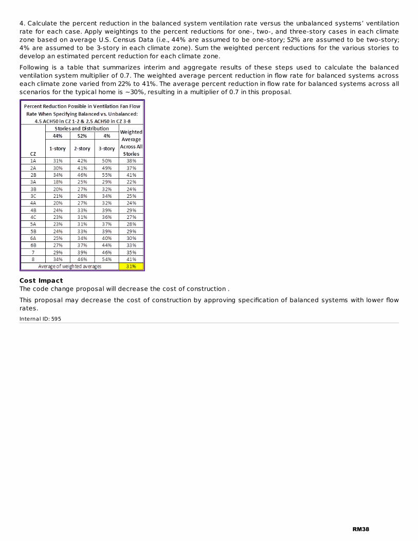
4. Calculate the percent reduction in the balanced system ventilation rate versus the unbalanced systems’ ventilationrate for each case. Apply weightings to the percent reductions for one-, two-, and three-story cases in each climatezone based on average U.S. Census Data (i.e., 44% are assumed to be one-story; 52% are assumed to be two-story;4% are assumed to be 3-story in each climate zone). Sum the weighted percent reductions for the various stories todevelop an estimated percent reduction for each climate zone.Following is a table that summarizes interim and aggregate results of these steps used to calculate the balancedventilation system multiplier of 0.7. The weighted average percent reduction in flow rate for balanced systems acrosseach climate zone varied from 22% to 41%. The average percent reduction in flow rate for balanced systems across allscenarios for the typical home is ~30%, resulting in a multiplier of 0.7 in this proposal.
Cost ImpactThe code change proposal will decrease the cost of construction .This proposal may decrease the cost of construction by approving specification of balanced systems with lower flowrates.Internal ID: 595
RM38

ASHRAE ASHRE1791 Tullie Circle NE
Atlanta GA 30329US
RM25-18IRC: M1505.1, 44Proponent: Mike Moore, representing The Home Ventilating Institute ([email protected])
2018 International Residential Code
Revise as follows:
M1505.1 General. Where local exhaust or whole-house mechanical ventilation is provided, the equipment ventilationsystem shall be designed in accordance with this section, or the ventilation system shall be designed in accordancewith ASHRAE 62.2.
Add new standard(s) follows:
62.2-2016:Ventilation and Acceptable Indoor Air Quality in Residential Buildings with Addenda b, d, k, l, q, and s.
Reason:This proposed modification would provide builders with the OPTION of using ASHRAE Standard 62.2 to comply with theventilation requirements of the IRC without requiring builders to use the standard. ASHRAE 62.2 is the ANSI standard forestablishing minimum acceptable indoor air quality for dwelling units. There are several reasons that builders may wantto use ASHRAE 62.2 instead of the IRC for compliance, including: greater flexibility for specifying climate-appropriateventilation controls, ability to achieve energy and cost savings for homeowners by shifting operation of the ventilationsystem to times when ambient temperature and humidity are favorable, flexibility to specify innovative systems thatcan be demonstrated to provide equivalent exposure to pollutants, ability to down-size and save money on balancedventilation equipment versus what may be required by the code, 62.2’s use by code-plus programs such as ENERGYSTAR and LEED, and ability to size the system as a function of measured dwelling unit air leakage instead of a one-size-fits-all approach.Cost ImpactThe code change proposal will not increase or decrease the cost of construction .Use of this standard is proposed as an OPTIONAL path. Costs associated with using 62.2 versus other compliancepaths will vary based on the application. As such, this proposal will neither decrease nor increase the cost ofconstruction. Internal ID: 533
RM39

(Equation 15-1)
ASHRAE ASHRE1791 Tullie Circle NE
Atlanta GA 30329US
RM26-18IMC: 202 (New); IRC: M1505.1, M1505.4.3, ordinalProponent: Pennie Feehan, representing Plumbing, Mechanical, and Fuel Gas Code Action Committee([email protected])
2018 International Mechanical Code
Add new def inition as follows:
BALANCED VENTILATION SYSTEM. A ventilation system where the total supply fan airflow is within 20 percent of thetotal exhaust fan airflow. The balanced system airflow is the average of the supply and exhaust airflows.
2018 International Residential Code
Revise as follows:
M1505.1 General. Where local exhaust or whole-house mechanical ventilation is provided, the equipment ventilationsystem shall be designed in accordance with this section.section, or the ventilation system shall be designed inaccordance with ASHRAE 62.2.
M1505.4.3 Mechanical ventilation rate. The whole house mechanical ventilation system shall provide outdoor airat a continuous rate as not less than that determined in accordance with Table M1505.4.3(1) or not less than thatdetermined by Equation 15-1.
Exception:Exceptions:
1. Ventilation rate credit. Where a balanced whole-house mechanical ventilation system isprovided, the whole-house mechanical ventilation system rate shall be permitted to be adjustedby multiplying the mechanical ventilation rate determined in accordance with Table M1505.4.3(1)or by Equation 15-1 by 0.7.
2. Programmed intermittent operation. The whole-house mechanical ventilation system is permittedto operate intermittently where the system has controls that enable operation for not less than25 percent of each 4-hour segment and the ventilation rate prescribed in Table M1505.4.3(1) , byEquation 15-1, or by Exception 1 is multiplied by the factor determined in accordance with TableM1505.4.3(2).
Add new standard(s) follows:
62.2-2016:Ventilation and Acceptable Indoor Air Quality in Residential Buildings with Addenda b, d, k, l, g, and s
Reason:Balanced mechanical ventilation systems provide superior ventilation to unbalanced systems, and should not berequired to provide the same rate as less effective, unbalanced systems to provide equivalent ventilation. Thisproposed credit for balanced ventilation is a simplified version that was derived from ASHRAE 62.2-2016 Equation 4.2(published in addendum s). The ASHRAE equation adjusts the balanced whole house ventilation flow rate as a functionof building air leakage, building height, and weather and shielding factor (which approximates climate zone). To simplifyapplication of the ASHRAE calculation for the IRC, we developed a one-size-fits-all balanced system factor using thefollowing methodology:1. Define a typical new, single-family detached home. The home characteristics were as follows: 2600 ft2; 3-bedroom;heights of 8, 17, and 26 feet above grade for one-, two- and three-story versions of the typical home; and leakage rateof 4.5 ACH50 in CZ 1-2 and 2.5 ACH50 in CZ 3-8. Note: Higher values for air leakage provide larger credits for balancedventilation systems. To be conservative, we assumed that the average home was slightly tighter than the 2018 IECC
RM40

maximum leakage rates of 5 ACH50 in CZ 1-2 and 3 ACH50 in CZ 3-8 (i.e., 4.5 ACH50 instead of 5 ACH50 in CZ 1-2 and2.5 ACH50 instead of 3 ACH50 in CZ 3-8).2. Calculate the average weather and shielding factor across each climate zone using over 1000 weather stationscatalogued in Appendix B of ASHRAE 62.2.3. Calculate the ASHRAE 62.2-2016 flow rates for balanced and unbalanced systems in the one-, two-, and three-storyversions of the typical home across all IECC climate zones using Equation 4.2 and the average weather and shieldingfactors calculated in step 2.4. Calculate the percent reduction in the balanced system ventilation rate versus the unbalanced systems’ ventilationrate for each case. Apply weightings to the percent reductions for one-, two-, and three-story cases in each climatezone based on average U.S. Census Data (i.e., 44% are assumed to be one-story; 52% are assumed to be two-story;4% are assumed to be 3-story in each climate zone). Sum the weighted percent reductions for the various stories todevelop an estimated percent reduction for each climate zone.Following is a table that summarizes interim and aggregate results of these steps used to calculate the balancedventilation system flow rate multiplier of 0.7. The weighted average percent reduction in flow rate for balancedsystems across each climate zone varied from 22% to 41%. The average percent reduction in flow rate for balancedsystems across all scenarios for the typical home is ~30%, resulting in a multiplier of 0.7 in this proposal.This proposal is submitted by the ICC Plumbing/Mechanical/Gas Code Action Committee (PMG CAC). The PMG CAC wasestablished by the ICC Board of Directors to pursue opportunities to improve and enhance the International Codes orportions thereof that were under the purview of the PMG CAC. In 2017 the PMG CAC held one face-to-face meeting and11 conference call meetings. Numerous interested parties attended the committee meetings and offered their input.Cost ImpactThe code change proposal will not increase or decrease the cost of construction .This proposal will not increase the cost of construction because no additional labor, materials, equipment, appliancesor devices are mandated beyond what is currently required by the code.
Analysis: A review of the standard proposed for inclusion in the code, with regard to the ICC criteria for referencedstandards (Section 3.6 of CP#28) will be posted on the ICC website on or before April 2, 2018.Internal ID: 569
RM41
RM27-18IRC: M1504.3Proponent: Pennie Feehan, representing Plumbing, Mechanical, and Fuel Gas Code Action Committee([email protected])
2018 International Residential Code
Revise as follows:
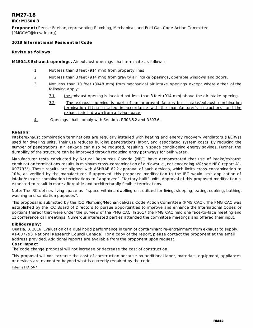
M1504.3 Exhaust openings. Air exhaust openings shall terminate as follows:
1. Not less than 3 feet (914 mm) from property lines.2. Not less than 3 feet (914 mm) from gravity air intake openings, operable windows and doors.3. Not less than 10 feet (3048 mm) from mechanical air intake openings except where either of the
following apply:3.1. the exhaust opening is located not less than 3 feet (914 mm) above the air intake opening.3.2. The exhaust opening is part of an approved factory-built intake/exhaust combination
termination fitting installed in accordance with the manufacturer's instructions, and theexhaust air is drawn from a living space.
4. Openings shall comply with Sections R303.5.2 and R303.6.
Reason:Intake/exhaust combination terminations are regularly installed with heating and energy recovery ventilators (H/ERVs)used for dwelling units. Their use reduces building penetrations, labor, and associated system costs. By reducing thenumber of penetrations, air leakage can also be reduced, resulting in space conditioning energy savings. Further, thedurability of the structure can be improved through reducing entry pathways for bulk water.Manufacturer tests conducted by Natural Resources Canada (NRC) have demonstrated that use of intake/exhaustcombination terminations results in minimum cross-contamination of airflows(i.e., not exceeding 4%; see NRC report A1-007793 ). These results are aligned with ASHRAE 62.2 approval of such devices, which limits cross-contamination to10%, as verified by the manufacturer. If approved, this proposed modification to the IRC would limit application ofintake/exhaust combination terminations to “approved”, “factory-built” units. Approval of this proposed modification isexpected to result in more affordable and architecturally flexible terminations.Note: The IRC defines living space as, “space within a dwelling unit utilized for living, sleeping, eating, cooking, bathing,washing and sanitation purposes”.This proposal is submitted by the ICC Plumbing/Mechanical/Gas Code Action Committee (PMG CAC). The PMG CAC wasestablished by the ICC Board of Directors to pursue opportunities to improve and enhance the International Codes orportions thereof that were under the purview of the PMG CAC. In 2017 the PMG CAC held one face-to-face meeting and11 conference call meetings. Numerous interested parties attended the committee meetings and offered their input.Bibliography:Ouazia, B. 2016. Evaluation of a dual hood performance in term of contaminant re-entrainment from exhaust to supply.A1-007793. National Research Council Canada. For a copy of the report, please contact the proponent at the emailaddress provided. Additional reports are available from the proponent upon request.Cost ImpactThe code change proposal will not increase or decrease the cost of construction .This proposal will not increase the cost of construction because no additional labor, materials, equipment, appliancesor devices are mandated beyond what is currently required by the code.Internal ID: 567
1
RM42
RM28-18IRC: M1503.4Proponent: Pennie Feehan, representing Plumbing, Mechanical, and Fuel Gas Code Action Committee([email protected])
2018 International Residential Code
Revise as follows:
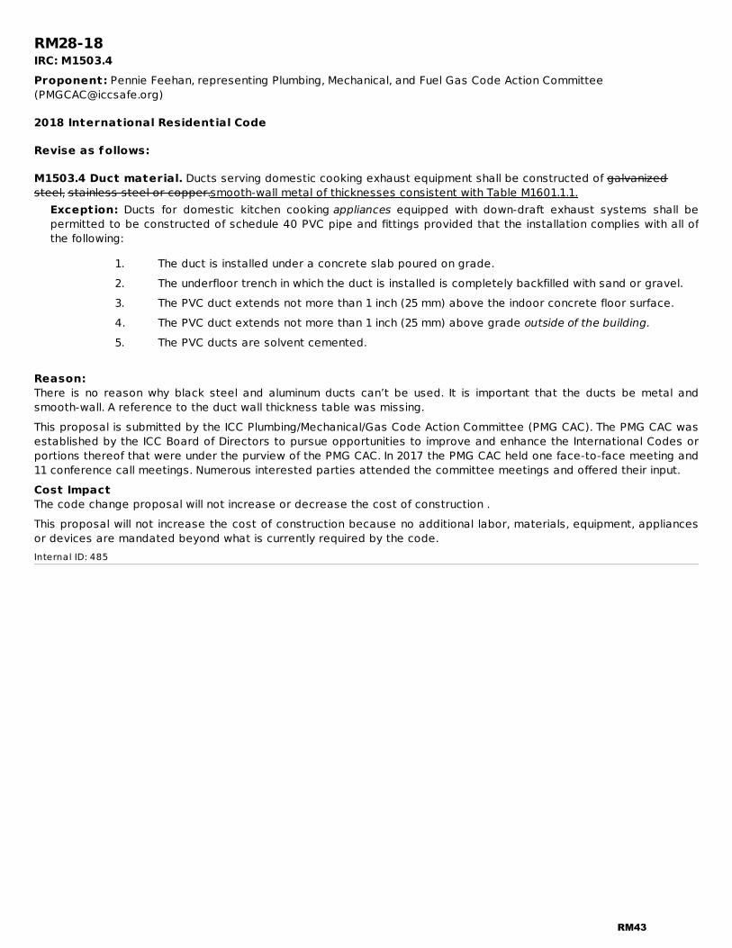
M1503.4 Duct material. Ducts serving domestic cooking exhaust equipment shall be constructed of galvanizedsteel, stainless steel or copper.smooth-wall metal of thicknesses consistent with Table M1601.1.1.
Exception: Ducts for domestic kitchen cooking appliances equipped with down-draft exhaust systems shall bepermitted to be constructed of schedule 40 PVC pipe and fittings provided that the installation complies with all ofthe following:
1. The duct is installed under a concrete slab poured on grade.2. The underfloor trench in which the duct is installed is completely backfilled with sand or gravel.3. The PVC duct extends not more than 1 inch (25 mm) above the indoor concrete floor surface.4. The PVC duct extends not more than 1 inch (25 mm) above grade outside of the building.
5. The PVC ducts are solvent cemented.
Reason:There is no reason why black steel and aluminum ducts can’t be used. It is important that the ducts be metal andsmooth-wall. A reference to the duct wall thickness table was missing.This proposal is submitted by the ICC Plumbing/Mechanical/Gas Code Action Committee (PMG CAC). The PMG CAC wasestablished by the ICC Board of Directors to pursue opportunities to improve and enhance the International Codes orportions thereof that were under the purview of the PMG CAC. In 2017 the PMG CAC held one face-to-face meeting and11 conference call meetings. Numerous interested parties attended the committee meetings and offered their input.Cost ImpactThe code change proposal will not increase or decrease the cost of construction .This proposal will not increase the cost of construction because no additional labor, materials, equipment, appliancesor devices are mandated beyond what is currently required by the code.Internal ID: 485
RM43

RM29-18IRC: M1505.4.2Proponent: Pennie Feehan, representing Plumbing, Mechanical, and Fuel Gas Code Action Committee([email protected])
2018 International Residential Code
Revise as follows:
M1505.4.2 System controls. The whole-house mechanical ventilation system shall be provided with controls thatenable manual override. Controls shall include text or a symbol indicating their function.
Reason:Tight dwelling units are being outfitted with code-mandated outdoor air/“whole-house” mechanical ventilation systems.These systems are often simply a bathroom exhaust fan expected to run continuously. The problem is that without alabel indicating the system's function, occupants have no idea of the purpose of these systems and are likely to turnthem off – thereby increasing the rate of accumulation of harmful indoor pollutants without their knowledge. At aminimum, these systems should be labeled to indicate that they are different than a typical bath fan. This proposedlanguage would echo language in ASHRAE 62.2 and also within the 2018 IMC as follows: “403.3.2.4 System controls.Where provided within a dwelling unit, controls for outdoor air ventilation systems shall include text or a symbolindicating the system's function.” The language is intended to be flexible enough to allow multiple options for the textor symbol, provided it achieves the intention of conveying that the control is for a system that is not merely a standardbath fan. For example, the Home Ventilating Institute (an industry association representing over 90% of themanufacturers of residential ventilating products in the U.S.), recently developed the following logo for this purpose:
This proposal is submitted by the ICC Plumbing/Mechanical/Gas Code Action Committee (PMG CAC). The PMG CAC wasestablished by the ICC Board of Directors to pursue opportunities to improve and enhance the International Codes orportions thereof that were under the purview of the PMG CAC. In 2017 the PMG CAC held one face-to-face meeting and11 conference call meetings. Numerous interested parties attended the committee meetings and offered their input.Cost ImpactThe code change proposal will increase the cost of construction .This proposal will increase the cost of construction because a label will be required on a switch cover.Internal ID: 563
RM44
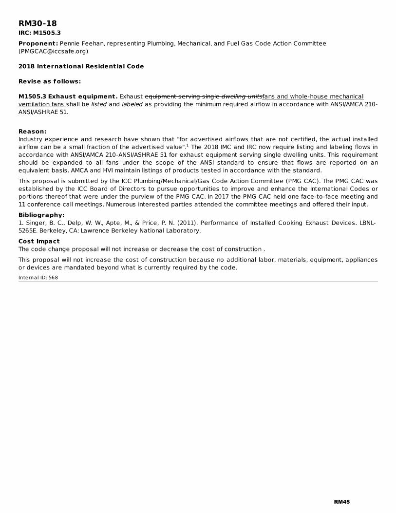
RM30-18IRC: M1505.3Proponent: Pennie Feehan, representing Plumbing, Mechanical, and Fuel Gas Code Action Committee([email protected])
2018 International Residential Code
Revise as follows:
M1505.3 Exhaust equipment. Exhaust equipment serving single dwelling unitsfans and whole-house mechanicalventilation fans shall be listed and labeled as providing the minimum required airflow in accordance with ANSI/AMCA 210-ANSI/ASHRAE 51.
Reason:Industry experience and research have shown that "for advertised airflows that are not certified, the actual installedairflow can be a small fraction of the advertised value". The 2018 IMC and IRC now require listing and labeling flows inaccordance with ANSI/AMCA 210-ANSI/ASHRAE 51 for exhaust equipment serving single dwelling units. This requirementshould be expanded to all fans under the scope of the ANSI standard to ensure that flows are reported on anequivalent basis. AMCA and HVI maintain listings of products tested in accordance with the standard.This proposal is submitted by the ICC Plumbing/Mechanical/Gas Code Action Committee (PMG CAC). The PMG CAC wasestablished by the ICC Board of Directors to pursue opportunities to improve and enhance the International Codes orportions thereof that were under the purview of the PMG CAC. In 2017 the PMG CAC held one face-to-face meeting and11 conference call meetings. Numerous interested parties attended the committee meetings and offered their input.Bibliography:1. Singer, B. C., Delp, W. W., Apte, M., & Price, P. N. (2011). Performance of Installed Cooking Exhaust Devices. LBNL-5265E. Berkeley, CA: Lawrence Berkeley National Laboratory.Cost ImpactThe code change proposal will not increase or decrease the cost of construction .This proposal will not increase the cost of construction because no additional labor, materials, equipment, appliancesor devices are mandated beyond what is currently required by the code.Internal ID: 568
1
RM45

RM31-18IRC: M1601.1.1Proponent: David Bixby, Air Conditioning Contractors of America (ACCA), representing Air Conditioning Contractors ofAmerica ([email protected])
2018 International Residential Code
Revise as follows:
M1601.1.1 Above-ground duct systems. Above-ground duct systems shall conform to the following:
1. Equipment connected to duct systems shall be designed to limit discharge air temperature to notgreater than 250°F (121°C).
2. Factory-made ducts shall be listed and labeled in accordance with UL 181 and installed inaccordance with the manufacturer's instructions.
3. Fibrous glass duct construction shall conform to the SMACNA Fibrous Glass Duct ConstructionStandards or NAIMA Fibrous Glass Duct Construction Standards.
4. Field-fabricated and shop-fabricated metal and flexible duct constructions shall conform to theSMACNA HVAC Duct Construction Standards-—Metal and Flexible except as allowed by TableM1601.1.1. Galvanized steel shall conform to ASTM A653.
5. The use of gypsum products to construct return air ducts or plenums is permitted, provided that theair temperature does not exceed 125°F (52°C) and exposed surfaces are not subject tocondensation.
6. Duct systems shall be constructed of materials having a flame spread index of not greater than200.
7. Stud wall cavities and the spaces between solid floor joists to be used as air plenums shall complywith the following conditions:7.1. These cavities or spaces shall not be used as a plenum for supply air.7.2. These cavities or spaces shall not be part of a required fire-resistance-rated assembly.7.3. Stud wall cavities shall not convey air from more than one floor level.7.4. Stud wall cavities and joist-space plenums shall be isolated from adjacent concealed
spaces by tight-fitting fireblocking in accordance with Section R602.8.7.5. Stud wall cavities in the outside walls of building envelope assemblies shall not be utilized
as air plenums.8. Volume dampers, equipment and other means of supply, return and exhaust air adjustment used in
system balancing shall be provided with access.9. Zoned duct systems shall be designed and installed in accordance with ACCA Manual Zr.
Reason:Currently there is no coverage in the residential code to address the design of zoned duct systems. ACCA Manual Zrprovides procedures for designing zoned comfort systems for single family detached homes, duplex and triplex homes,row houses, town houses, and large multi-family structures that are compatible with ACCA Manual J procedures forresidential load calculations. In addition, use of Manual Zr will avoid the potential for an improperly designed zonedduct system to adversely impact the safe operation and durability of the heating/cooling equipment. For code officials,Manual Zr has three normative sections to determine clear compliance. Manual Zr is also a consensus-based ANSIstandard.Cost ImpactThe code change proposal will not increase or decrease the cost of construction .Cost impacts for using Manual Zr would be minimal, other than some extra time involved. Installers will have to ensurethe installation of equipment and zoning devices complies with OEM installation instructions, as well as documentingsuch. Code officials will have to verify and document airflow rates, set-points for operation and safety controls, whichwill involve minimal time.
Analysis: A review of the standard proposed for inclusion in the code, with regard to the ICC criteria for referenced
RM46

standards (Section 3.6 of CP#28) will be posted on the ICC website on or before April 2, 2018.Internal ID: 1860
RM47

RM32-18IRC: M1601.1.1, M1601.4.5Proponent: Pennie Feehan, representing Plumbing, Mechanical, and Fuel Gas Code Action Committee([email protected])
2018 International Residential Code
Revise as follows:
M1601.1.1 Above-ground duct systems. Above-ground duct systems shall conform to the following:
1. Equipment connected to duct systems shall be designed to limit discharge air temperature to notgreater than 250°F (121°C).
2. Factory-made ducts shall be listed and labeled in accordance with UL 181 and installed inaccordance with the manufacturer's instructions.
3. Fibrous glass duct construction shall conform to the SMACNA Fibrous Glass Duct ConstructionStandards or NAIMA Fibrous Glass Duct Construction Standards.
4. Field-fabricated and shop-fabricated metal and flexible duct constructions shall conform to theSMACNA HVAC Duct Construction Standards-—Metal and Flexible except as allowed by TableM1601.1.1. Galvanized steel shall conform to ASTM A653.
5. The use of gypsum products to construct return air ducts or plenums is permitted, provided that theair temperature does not exceed 125°F (52°C) and exposed surfaces are not subject tocondensation.
6. Duct systems shall be constructed of materials having a flame spread index of not greater than200.
7. Stud wall cavities and the spaces between solid floor joists to be used as air plenums shall complywith the following conditions:7.1. These cavities or spaces shall not be used as a plenum for supply air.7.2. These cavities or spaces shall not be part of a required fire-resistance-rated assembly.7.3. Stud wall cavities shall not convey air from more than one floor level.7.4. Stud wall cavities and joist-space plenums shall be isolated from adjacent concealed
spaces by tight-fitting fireblocking in accordance with Section R602.8.R302.11. Fireblockingmaterials used for isolation shall comply with Section R302.11.1.
7.5. Stud wall cavities in the outside walls of building envelope assemblies shall not be utilizedas air plenums.
8. Volume dampers, equipment and other means of supply, return and exhaust air adjustment used insystem balancing shall be provided with access.
M1601.4.5 Fireblocking. Duct installations shall be fireblocked in accordance with Section R602.8.R302.11.
Reason:The current text creates an unnecessary step by taking the reader to R602.8, only to be redirected to R302.11.1. Thisproposal is a nontechnical cleanup of text.This proposal is submitted by the ICC Plumbing/Mechanical/Gas Code Action Committee (PMG CAC). The PMG CAC wasestablished by the ICC Board of Directors to pursue opportunities to improve and enhance the International Codes orportions thereof that were under the purview of the PMG CAC. In 2017 the PMG CAC held one face-to-face meeting and11 conference call meetings. Numerous interested parties attended the committee meetings and offered their input.Cost ImpactThe code change proposal will not increase or decrease the cost of construction .This proposal will not increase the cost of construction because no additional labor, materials, equipment, appliancesor devices are mandated beyond what is currently required by the code.Internal ID: 382
RM48
RM33-18IRC: M1601.1.1.7 (New)Proponent: Pennie Feehan, representing Plumbing, Mechanical, and Fuel Gas Code Action Committee([email protected])
2018 International Residential Code
Add new text as follows:
M1601.1.1.7 Sealing. Building cavities used as plenums shall be sealed.
Reason:Where stud cavities and joist cavities are used for return air, the negative pressure in the cavities can draw in outdoorair at any point where the cavities abut attic spaces, crawl spaces and outside walls. Sealing of the interface withattics, crawls and outside walls will reduce unwanted infiltration of outdoor air and will improve system efficiency.This proposal is submitted by the ICC Plumbing/Mechanical/Gas Code Action Committee (PMG CAC). The PMG CAC wasestablished by the ICC Board of Directors to pursue opportunities to improve and enhance the International Codes orportions thereof that were under the purview of the PMG CAC. In 2017 the PMG CAC held one face-to-face meeting and11 conference call meetings. Numerous interested parties attended the committee meetings and offered their input.Cost ImpactThe code change proposal will increase the cost of construction .This proposal will increase the cost of construction because additional labor and sealants are requiredInternal ID: 381
RM49

RM34-18IRC: M1802.4 (New)Proponent: Pennie Feehan, representing Plumbing, Mechanical, and Fuel Gas Code Action Committee([email protected])
2018 International Residential Code
Add new text as follows:
M1802.4 Blocked vent switch. The venting system for oil-fired appliances shall be equipped with a device that willstop burner operation in the event that the venting system is obstructed. Such device shall have a manual reset, andshall be installed in accordance with the manufacturer's instructions.
Reason:Such devices can save lives in the event that a chimney or Type L vent is blocked by debris, decaying masonry or deadanimals. Gas furnaces are equipped with thermal and/or pressure devices that will sense failure of the venting system,but such is not known to be required for oil-fired appliances. Such devices have been installed for many decades, butnot necessarily required. These devices are typically provided for or are an option for draft regulators that arecommonly installed in the vent of oil-fIred appliances.This proposal is submitted by the ICC Plumbing/Mechanical/Gas Code Action Committee (PMG CAC). The PMG CAC wasestablished by the ICC Board of Directors to pursue opportunities to improve and enhance the International Codes orportions thereof that were under the purview of the PMG CAC. In 2017 the PMG CAC held one face-to-face meeting and11 conference call meetings. Numerous interested parties attended the committee meetings and offered their input.Cost ImpactThe code change proposal will increase the cost of construction .This proposal will increase the cost of construction because an additional device is mandated beyond what is currentlyrequired by the code.Internal ID: 431
RM50
RM35-18IRC: M2101.11 (New), M2101.21.6 (New), M2101.20.4 (New), M2101.21 (New), M2101.21.1 (New), M2101.21.2(New), M2101.21.3 (New), M2101.21.4 (New), M2101.21.5 (New), M2101.22 (New), M2101.20.2 (New),M2101.23 (New), M2101.24 (New), M2101.25 (New), M2101.26 (New), M2101.27 (New), M2101.28 (New),M2101.28.1 (New), M2101.29 (New), M2101.20.3 (New), M2101.20.1 (New), M2101.12 (New), M2101.17 (New),M2101.13 (New), M2101.13.1 (New), M2101.14 (New), M2101.15 (New), M2101.15.1 (New), M2101.15.2 (New),M2101.16 (New), M2101.16.1 (New), M2101.17.1 (New), M2101.20 (New), M2101.17.2 (New), M2101.18 (New),M2101.18.1 (New), M2101.18.2 (New), M2101.18.3 (New), M2101.19 (New), M2101.19.1 (New), M2101.19.2(New), M2101.30 (New)Proponent: Pennie Feehan, representing Plumbing, Mechanical, and Fuel Gas Code Action Committee([email protected])
2018 International Residential Code
Add new text as follows:
M2101.11 Used materials. Used pipe, fittings, valves, and other materials shall not be reused in hydronic systems.
M2101.21.6 Expansion tanks. Shutoff valves shall be installed at connections to nondiaphragm-type expansiontanks.
M2101.20.4 Electrofusion joints. Joints shall be of the electrofusion type. Joint surfaces shall be clean and freefrom moisture and scoured to exp0ose virgin resin. Joint surfaces shall be heated to melt temperatures for the periodof time specified by the manufacturer and joined. The joint shall remain undisturbed until cool. Fittings shall bemanufactured in accordance with ASTM F105..
M2101.21 PVC plastic pipe. Joints between PVC plastic pipe or fittings shall be solvent-cemented in accordance withSection P2906.9.1.4. Threaded joints between fittings and PVC plastic pipe shall be in accordance with SectionM2101.16.1.
M2101.21 Shutof f valves. Shutoff valves shall be installed in ground-source loop piping systems in the locationsindicated in Sections M2101.21.1 through M2101.21.6.
M2101.21.1 Heat exchangers. Shut off valves shall be installed on the supply and return side of a heat exchanger.Exception: Shutoff valves shall not be required where heat exchangers are integral with a boiler or are acomponent of a manufacturer's boiler and heat exchanger packaged unit and are capable of being isolated from thehydronic system by the supply and return valves required by Section M2001.3.
M2101.21.2 Central systems. Shutoff valves shall be installed on the building supply and return of a central utilitysystem.
M2101.21.3 Pressure vessels. Shutoff valves shall be installed on the connection to any pressure vessel.
M2101.21.4 Pressure-reducing valves. Shutoff valves shall be installed on both sides of a pressure-reducingvalve.
M2101.21.5 Equipment and appliances. `Shutoff valves shall be installed on connections to mechanical equipmentand appliances. This requirement does not apply to components of ground-source loop systems such as pumps, airseparators, metering devices, and similar equipment.
M2101.22 Reduced pressure. A pressure relief valve shall be installed on the low-pressure side of a hydronic pipingsystem that has been reduced in pressure. The relief valve shall be set at the maximum pressure of the system design.The valve shall be installed in accordance with Section M2002.
M2101.20.2 PE-RT-to-metal connections. Solder joints in a metal pipe shall not occur within 18 inches (457 mm)of a transition from such metal pipe to PE-RT pipe or tubing.
M2101.23 Installation. Piping, valves, fittings, and connections shall be installed in accordance with themanufacturer's instructions.
M2101.24 Protection of potable water. Where hydronic systems have a connection to a potable water supply,
RM51

the potable water system shall be protected from backflow in accordance with Section P2902.
M2101.25 Pipe penetrations. Openings for pipe penetrations in walls, floors and ceilings shall be larger than thepenetrating pipe. Openings through concrete or masonry building elements shall be sleeved. The annular spacesurrounding pipe penetrations shall be protected in accordance with Section P2606.1.
M2101.26 Clearance f rom combustibles. A pipe in a piping system having an exterior surface temperatureexceeding 250ºF (121ºC) shall have a clearance of not less than 1 inch (25 mm) from combustible materials.
M2101.27 Contact with building material. A piping system shall not be in direct contact with building materialsthat cause the piping or fitting material to degrade or corrode, or that interfere with the operation of the system.
M2101.28 Strains and stresses. Piping shall be installed so as to prevent detrimental strains and stresses in thepipe. Provisions shall be made to protect piping from damage resulting from expansion, contraction and structuralsettlement. Piping shall be installed so as to avoid structural stresses or strains within building components.
M2101.28.1 Flood hazard. . Piping located in a flood hazard area shall be capable of resisting hydrostatic andhydrodynamic loads and stresses, including the effects of buoyancy, during the occurrence of flooding to the designflood elevation.
M2101.29 Chemical compatibility. Antifreeze and other materials used in the system shall be chemicallycompatible with the pipe, tubing, fittings and mechanical systems.
M2101.20.3 Heat-fusion joints. Heat-fusion joints shall be of the socket-fusion, saddle-fusion or butt-fusion type,and shall be joined in accordance with ASTM D2657. Joint surfaces shall be clean and free from moisture. Joint surfacesshall be heated to melt temperatures and joined. The joint shall remain undisturbed until cool. Fittings shall bemanufactured in accordance with ASTM D2683 or ASTM D3261.
M2101.20.1 Compression-type f ittings. Where compression-type fittings include inserts and ferrules or O-rings,the fittings shall be installed without omitting the inserts and ferrules or O-rings.
M2101.12 Material rating. Pipe and tubing shall be rated for the operating temperature and pressure of thesystem. Fittings shall be suitable for the pressure applications and recommended by the manufacturer for installationwith the pipe and tubing material installed. Where used underground, materials shall be suitable for burial.
M2101.17 Cross-linked polyethylene (PEX) plastic tubing. Joints between cross-linked polyethylene plastictubing and fittings shall comply with Sections M2101.17.1 and M2101.17.2. Mechanical joints shall comply with SectionM2101.15.1.
M2101.13 Joints and connections. Joints and connections shall be of an approved type. Joints and connections shallbe tight for the pressure of the system. Joints used underground shall be approved for such applications.
M2101.13.1 Joints between dif ferent piping materials. Joints between different piping materials shall be madewith approved transition fittings.
M2101.14 Preparation of pipe ends. Pipe shall be cut square, reamed, and shall be free of burrs and obstructions.CPVC, PE, and PVC pipe shall be chamfered. Pipe ends shall have full-bore openings and shall not be undercut.
M2101.15 Joint preparation and installation. Where required by Sections M2101.16 through M2101.18, thepreparation and installation of mechanical and thermoplastic-welded joints shall comply with Sections M2101.15.1 andM2101.15.2.
M2101.15.1 Mechanical joints. Mechanical joints shall be installed in accordance with the manufacturer'sinstructions.
M2101.15.2 Thermoplastic-welded joints. Joint surfaces for thermoplastic-welded joints shall be cleaned by anapproved procedure. Joints shall be welded in accordance with the manufacturer's instructions.
M2101.16 CPVC plastic pipe. Joints between CPVC plastic pipe or fittings shall be solvent-cemented in accordancewith Section P2906.9.1.2. Threaded joints between fittings and CPVC plastic pipe shall be in accordance with SectionM2101.16.1
RM52
M2101.16.1 Threaded joints. Threads shall conform to ASME B1.20.1 The pipe shall be Schedule 80 40 or heavierplastic pipe and shall be threaded with dies specifically designed for plastic pipe. Thread lubricant, pipe-jointcompound or tape shall be applied on the male threads only and shall be approved for application on the pipingmaterial.
M2101.17.1 Compression-type f ittings. Where compression-type fittings include inserts and ferrules or O-rings,the fittings shall be installed without omitting the inserts and ferrules or O-rings.
M2101.20 Raised temperature polyethylene (PE-RT) plastic tubing. Joints between raised temperaturepolyethylene tubing and fittings shall comply with Sections M2101.20.1 through M2101.20.4. Mechanical joints shallcomply with Section M2101.15.1.
M2101.17.2 Plastic-to-metal. Solder joints in a metal pipe shall not occur within 18 inches (457 mm) of a transitionfrom such metal pipe to plastic pipe or tubing.
M2101.18 Polyethylene plastic pipe and tubing. Joints between polyethylene plastic pipe and tubing or fittingsfor systems shall be heat-fusion joints complying with Section M2101.18.1, electrofusion joints complying with SectionM2101.18.2, or stab-type insertion joints complying with Section M2101.18.3.
M2101.18.1 Heat-fusion joints. Joints shall be of the socket-fusion, saddle-fusion or butt-fusion type, and joined inaccordance with ASTM D2657. Joint surfaces shall be clean and free from moisture. Joint surfaces shall be heated tomelt temperatures and joined. The joint shall remain undisturbed until cool. Fittings shall be manufactured inaccordance with ASTM D2683 or ASTM D3261.
M2101.18.2 Electrofusion joints. Joints shall be of the electrofusion type. Joint surfaces shall be clean and freefrom moisture, and scoured to expose virgin resin. Joint surfaces shall be heated to melt temperatures for the period oftime specified by the manufacturer. The joint shall remain undisturbed until cool. Fittings shall be manufactured inaccordance with ASTM F1055.
M2101.18.3 Stab-type insert f ittings. Joint surfaces shall be clean and free from moisture. Pipe ends shall bechamfered and inserted into the fittings to full depth. Fittings shall be manufactured in accordance with ASTM F1924.
M2101.19 Polyproplyene (PP) plastic. Joints between PP plastic pipe and fittings shall comply with SectionsM2101.19.1 and M2101.19.2.
M2101.19.1 Heat-fusion joints. Heat-fusion joints for polypropylene (PP) pipe and tubing joints shall be installedwith socket-type heat-fused polypropylene fittings, electrofusion polypropylene fittings or by butt fusion. Joint surfacesshall be clean and free from moisture. The joint shall remain undisturbed until cool. Joints shall be made in accordancewith ASTM F2389.
M2101.19.2 Mechanical and compression sleeve joints. Mechanical and compression sleeve joints shall beinstalled in accordance with the manufacturer's instructions.
M2101.30 Makeup water. The transfer fluid shall be compatible with the makeup water supplied to the system.
Reason:This proposal fills a gap in the code coverage for hydronic piping. The new text is simply borrowed from Section M1205which is specific to ground-source heat-pump loop piping. The same requirements also need to apply to all hydronicpiping systems under Section M2101, not just ground-source heat- pump systems. This proposal provides the samecoverage for general hydronic systems as is currently required for ground-source heat-pump systems.This proposal is submitted by the ICC Plumbing/Mechanical/Gas Code Action Committee (PMG CAC). The PMG CAC wasestablished by the ICC Board of Directors to pursue opportunities to improve and enhance the International Codes orportions thereof that were under the purview of the PMG CAC. In 2017 the PMG CAC held one face-to-face meeting and11 conference call meetings. Numerous interested parties attended the committee meetings and offered their input.Cost ImpactThe code change proposal will not increase or decrease the cost of construction .This proposal will not increase the cost of construction because no additional labor, materials, equipment, appliancesor devices are mandated beyond what is currently required by the code.Internal ID: 432
RM53
RM36-18IRC: TABLE M2105.4Proponent: LANCE MacNevin, Plastics Pipe Institute, representing Plastics Pipe Institute ([email protected]);Mark Metzner, IGSHPA Canada, representing IGSHPA Canada ([email protected])
2018 International Residential Code
Revise as follows:
RM54
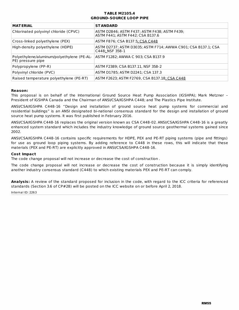
TABLE M2105.4GROUND-SOURCE LOOP PIPE
MATERIAL STANDARDChlorinated polyvinyl chloride (CPVC) ASTM D2846; ASTM F437; ASTM F438; ASTM F439;
ASTM F441; ASTM F442; CSA B137.6Cross-linked polyethylene (PEX) ASTM F876; CSA B137.5; CSA C448High-density polyethylene (HDPE) ASTM D2737; ASTM D3035; ASTM F714; AWWA C901; CSA B137.1; CSA
C448; NSF 358-1Polyethylene/aluminum/polyethylene (PE-AL-PE) pressure pipe
ASTM F1282; AWWA C 903; CSA B137.9
Polypropylene (PP-R) ASTM F2389; CSA B137.11, NSF 358-2Polyvinyl chloride (PVC) ASTM D1785; ASTM D2241; CSA 137.3Raised temperature polyethylene (PE-RT) ASTM F2623; ASTM F2769, CSA B137.18; CSA C448
Reason:This proposal is on behalf of the International Ground Source Heat Pump Association (IGSHPA); Mark Metzner –President of IGSHPA Canada and the Chairman of ANSI/CSA/IGSHPA C448; and The Plastics Pipe Institute.ANSI/CSA/IGSHPA C448-16 “Design and installation of ground source heat pump systems for commercial andresidential buildings” is an ANSI designated bi-national consensus standard for the design and installation of groundsource heat pump systems. It was first published in February 2016.ANSI/CSA/IGSHPA C448-16 replaces the original version known as CSA C448-02. ANSI/CSA/IGSHPA C448-16 is a greatlyenhanced system standard which includes the industry knowledge of ground source geothermal systems gained since2002.ANSI/CSA/IGSHPA C448-16 contains specific requirements for HDPE, PEX and PE-RT piping systems (pipe and fittings)for use as ground loop piping systems. By adding reference to C448 in these rows, this will indicate that thesematerials (PEX and PE-RT) are explicitly approved in ANSI/CSA/IGSHPA C448-16.Cost ImpactThe code change proposal will not increase or decrease the cost of construction .The code change proposal will not increase or decrease the cost of construction because it is simply identifyinganother industry consensus standard (C448) to which existing materials PEX and PE-RT can comply.
Analysis: A review of the standard proposed for inclusion in the code, with regard to the ICC criteria for referencedstandards (Section 3.6 of CP#28) will be posted on the ICC website on or before April 2, 2018.Internal ID: 2263
RM55

RM37-18IRC: M2105.17Proponent: LANCE MacNevin, Plastics Pipe Institute, representing Plastics Pipe Institute ([email protected]);Mark Metzner, IGSHPA Canada, representing IGSHPA Canada ([email protected])
2018 International Residential Code
Revise as follows:
M2105.17 Installation. Piping, valves, fittings, and connections shall be installed in accordance withANSI/CSA/IGSHPA C448 and the manufacturer's instructions.
Reason:This proposal is on behalf of the International Ground Source Heat Pump Association (IGSHPA); Mark Metzner –President of IGSHPA Canada and the Chairman of ANSI/CSA/IGSHPA C448; and The Plastics Pipe Institute.ANSI/CSA/IGSHPA C448-16 “Design and installation of ground source heat pump systems for commercial andresidential buildings” is an ANSI designated bi-national consensus standard for the design and installation of groundsource heat pump systems. It was first published in February 2016.ANSI/CSA/IGSHPA C448-16 is the first ANSI approved consensus standard for the design and installation of groundsource systems.ANSI/CSA/IGSHPA C448-16 replaces the original version known as CSA C448-02. ANSI/CSA/IGSHPA C448-16 is a greatlyenhanced system standard which includes the industry knowledge of ground source geothermal systems gained since2002. Ground loop piping system installations should be in accordance with the requirements of this standard.The Standard includes performance-based criteria that provides a consistent application of requirements and bestpractices throughout the United States and Canada. This Standard will ensure that stakeholders in the ground sourceheat pump systems market sector will supply and receive ground source heating / cooling systems that perform todesign efficiency expectations and deliver true, long-term value.This Standard was developed by a Binational Technical Committee which comprised of the industry's leaders fromCanada and USA, including representatives of the following industry associations:American Society for Heating, Refrigeration and Air Conditioning Engineers (ASHRAE)Geothermal Exchange Organization (GEO)International Ground Source Heat Pump Association (IGSPHA)International Ground Source Heat Pump Association Canada (IGSPHA - Canada)National Ground Water Association (NGWA)The Plastics Pipe Institute (PPI)Geothermal National & International Initiative (GEONII)Heating, Refrigeration and Air Conditioning Institute of Canada (HRAI)ANSI/CSA/IGSHPA C448-16 includes performance-based minimum requirements for industrial, commercial, institutionaland residential applications. It addresses the following items related to ground source heat pump systems:equipment and material selection (including ground loop piping)site survey - geological and hydrogeologicalopen and closed loop ground source heat pump system design / engineeringdirect expansion (DX) systemsinstallationtesting and verificationdocumentationcommissioning and decommissioningANSI/CSA/IGSHPA C448-16 applies to all ground source heat pump systems using outdoor ground loop heatexchangers as a thermal source or sink for heating and cooling, with or without supplementary heating or coolingsource/s. The types of outdoor heat exchangers covered by this Standard include:ground heat exchangers - vertical and horizontalopen-loop systems - drilled well and surface watersubmerged closed loop systems - fresh water and sea waterstanding column wellsCost ImpactThe code change proposal will not increase or decrease the cost of construction .
RM56

The code change proposal will not increase or decrease the cost of construction because it is simply clarifying thatground loop pipes must be installed correctly, in accordance with the latest version of this industry consensusstandard which is already referenced in the IMC and IRC.
Analysis: A review of the standard proposed for inclusion in the code, with regard to the ICC criteria for referencedstandards (Section 3.6 of CP#28) will be posted on the ICC website on or before April 2, 2018.Internal ID: 2274
RM57

RM38-18IRC: TABLE M2105.5Proponent: LANCE MacNevin, Plastics Pipe Institute, representing Plastics Pipe Institute ([email protected]);Mark Metzner, IGSHPA Canada, representing IGSHPA Canada ([email protected])
2018 International Residential Code
RM58
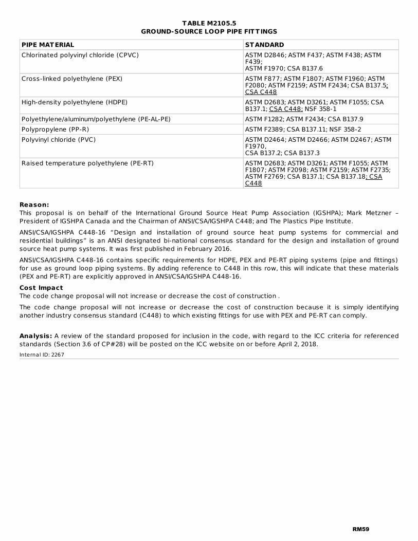
TABLE M2105.5GROUND-SOURCE LOOP PIPE FITT INGS
PIPE MATERIAL STANDARDChlorinated polyvinyl chloride (CPVC) ASTM D2846; ASTM F437; ASTM F438; ASTM
F439;ASTM F1970; CSA B137.6
Cross-linked polyethylene (PEX) ASTM F877; ASTM F1807; ASTM F1960; ASTMF2080; ASTM F2159; ASTM F2434; CSA B137.5;CSA C448
High-density polyethylene (HDPE) ASTM D2683; ASTM D3261; ASTM F1055; CSAB137.1; CSA C448; NSF 358-1
Polyethylene/aluminum/polyethylene (PE-AL-PE) ASTM F1282; ASTM F2434; CSA B137.9Polypropylene (PP-R) ASTM F2389; CSA B137.11; NSF 358-2Polyvinyl chloride (PVC) ASTM D2464; ASTM D2466; ASTM D2467; ASTM
F1970,CSA B137.2; CSA B137.3
Raised temperature polyethylene (PE-RT) ASTM D2683; ASTM D3261; ASTM F1055; ASTMF1807; ASTM F2098; ASTM F2159; ASTM F2735;ASTM F2769; CSA B137.1; CSA B137.18; CSAC448
Reason:This proposal is on behalf of the International Ground Source Heat Pump Association (IGSHPA); Mark Metzner –President of IGSHPA Canada and the Chairman of ANSI/CSA/IGSHPA C448; and The Plastics Pipe Institute.ANSI/CSA/IGSHPA C448-16 “Design and installation of ground source heat pump systems for commercial andresidential buildings” is an ANSI designated bi-national consensus standard for the design and installation of groundsource heat pump systems. It was first published in February 2016.ANSI/CSA/IGSHPA C448-16 contains specific requirements for HDPE, PEX and PE-RT piping systems (pipe and fittings)for use as ground loop piping systems. By adding reference to C448 in this row, this will indicate that these materials(PEX and PE-RT) are explicitly approved in ANSI/CSA/IGSHPA C448-16.Cost ImpactThe code change proposal will not increase or decrease the cost of construction .The code change proposal will not increase or decrease the cost of construction because it is simply identifyinganother industry consensus standard (C448) to which existing fittings for use with PEX and PE-RT can comply.
Analysis: A review of the standard proposed for inclusion in the code, with regard to the ICC criteria for referencedstandards (Section 3.6 of CP#28) will be posted on the ICC website on or before April 2, 2018.Internal ID: 2267
RM59

RM39-18IRC: TABLE M2105.4, TABLE M2105.5, ordinalProponent: Jeremy Brown, representing NSF International ([email protected])
2018 International Residential Code
Revise as follows:
RM60
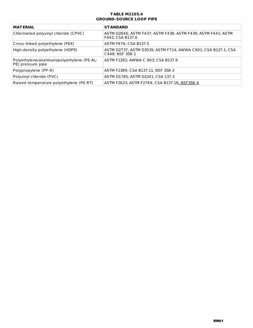
TABLE M2105.4GROUND-SOURCE LOOP PIPE
MATERIAL STANDARDChlorinated polyvinyl chloride (CPVC) ASTM D2846; ASTM F437; ASTM F438; ASTM F439; ASTM F441; ASTM
F442; CSA B137.6Cross-linked polyethylene (PEX) ASTM F876; CSA B137.5High-density polyethylene (HDPE) ASTM D2737; ASTM D3035; ASTM F714; AWWA C901; CSA B137.1; CSA
C448; NSF 358-1Polyethylene/aluminum/polyethylene (PE-AL-PE) pressure pipe
ASTM F1282; AWWA C 903; CSA B137.9
Polypropylene (PP-R) ASTM F2389; CSA B137.11, NSF 358-2Polyvinyl chloride (PVC) ASTM D1785; ASTM D2241; CSA 137.3Raised temperature polyethylene (PE-RT) ASTM F2623; ASTM F2769, CSA B137.18, NSF358-4
RM61
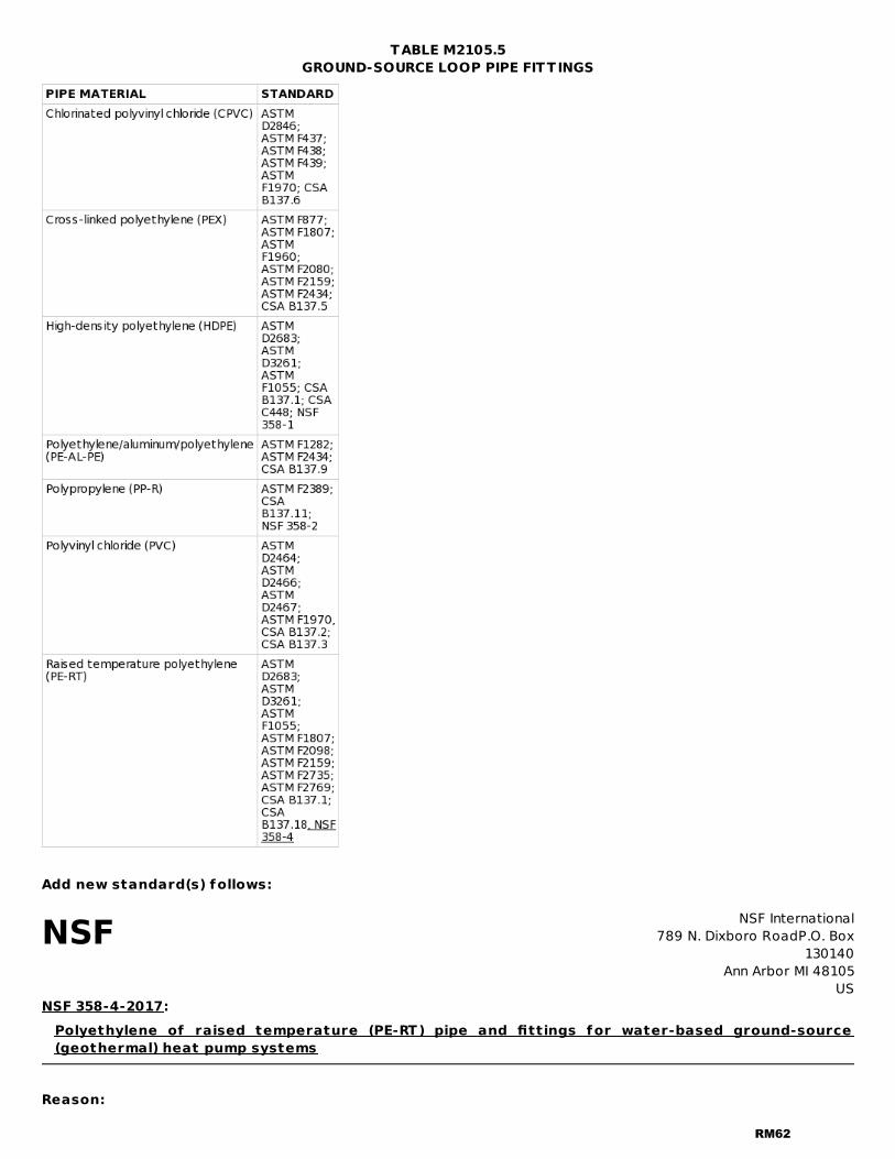
NSF NSF International789 N. Dixboro RoadP.O. Box
130140Ann Arbor MI 48105
US
TABLE M2105.5GROUND-SOURCE LOOP PIPE FITT INGS
Add new standard(s) follows:
NSF 358-4-2017:Polyethylene of raised temperature (PE-RT) pipe and fittings for water-based ground-source(geothermal) heat pump systems
Reason:
RM62

At the proposal deadline, NSF 358-4 was still a draft standard, but it is expected to be published prior to the publichearing. The balloted draft standard will be submitted with the proposal. Anyone may receive a complimentary copy ofthis draft standard for the purpose of reviewing this proposal by emailing [email protected] tables contain the acceptable materials for geothermal ground loop pipe and fittings. PE-RT piping andassociated fittings are already accepted materials with referenced standards. NSF 358-4 is a proposed ANSI standardwritten specifically to contain requirements for PE-RT geothermal piping and fittings. Companion standards NSF 358-1(PE) and NSF 358-3(PP) are already approved in this table. NSF 358-4 addresses performance pressure testing, longterm strength, chemical resistance, constant tensile load joint testing, suitability for burial and marking specific togeothermal PE-RT piping systems.Cost ImpactThe code change proposal will not increase or decrease the cost of construction .Providing an additional option is cost neutral.
Analysis: A review of the standard proposed for inclusion in the code, with regard to the ICC criteria for referencedstandards (Section 3.6 of CP#28) will be posted on the ICC website on or before April 2, 2018.Internal ID: 1088
RM63
RM40-18IRC: TABLE M2105.4, TABLE M2105.5, ordinalProponent: Jeremy Brown, representing NSF International ([email protected])
2018 International Residential Code
Revise as follows:
RM64

TABLE M2105.4GROUND-SOURCE LOOP PIPE
MATERIAL STANDARDChlorinated polyvinyl chloride(CPVC)
ASTM D2846; ASTM F437; ASTM F438; ASTM F439; ASTM F441; ASTM F442; CSAB137.6
Cross-linked polyethylene (PEX) ASTM F876; CSA B137.5, NSF 358-3High-density polyethylene (HDPE) ASTM D2737; ASTM D3035; ASTM F714; AWWA C901; CSA B137.1; CSA C448; NSF
358-1Polyethylene/aluminum/polyethylene(PE-AL-PE) pressure pipe
ASTM F1282; AWWA C 903; CSA B137.9
Polypropylene (PP-R) ASTM F2389; CSA B137.11, NSF 358-2Polyvinyl chloride (PVC) ASTM D1785; ASTM D2241; CSA 137.3Raised temperature polyethylene(PE-RT)
ASTM F2623; ASTM F2769, CSA B137.18
RM65
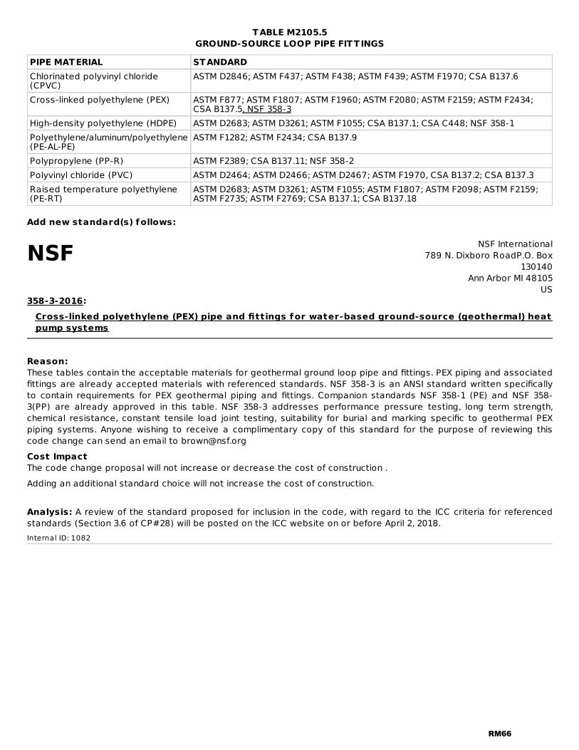
NSF NSF International789 N. Dixboro RoadP.O. Box
130140Ann Arbor MI 48105
US
TABLE M2105.5GROUND-SOURCE LOOP PIPE FITT INGS
PIPE MATERIAL STANDARDChlorinated polyvinyl chloride(CPVC)
ASTM D2846; ASTM F437; ASTM F438; ASTM F439; ASTM F1970; CSA B137.6
Cross-linked polyethylene (PEX) ASTM F877; ASTM F1807; ASTM F1960; ASTM F2080; ASTM F2159; ASTM F2434;CSA B137.5, NSF 358-3
High-density polyethylene (HDPE) ASTM D2683; ASTM D3261; ASTM F1055; CSA B137.1; CSA C448; NSF 358-1Polyethylene/aluminum/polyethylene(PE-AL-PE)
ASTM F1282; ASTM F2434; CSA B137.9
Polypropylene (PP-R) ASTM F2389; CSA B137.11; NSF 358-2Polyvinyl chloride (PVC) ASTM D2464; ASTM D2466; ASTM D2467; ASTM F1970, CSA B137.2; CSA B137.3Raised temperature polyethylene(PE-RT)
ASTM D2683; ASTM D3261; ASTM F1055; ASTM F1807; ASTM F2098; ASTM F2159;ASTM F2735; ASTM F2769; CSA B137.1; CSA B137.18
Add new standard(s) follows:
358-3-2016:Cross-linked polyethylene (PEX) pipe and fittings for water-based ground-source (geothermal) heatpump systems
Reason:These tables contain the acceptable materials for geothermal ground loop pipe and fittings. PEX piping and associatedfittings are already accepted materials with referenced standards. NSF 358-3 is an ANSI standard written specificallyto contain requirements for PEX geothermal piping and fittings. Companion standards NSF 358-1 (PE) and NSF 358-3(PP) are already approved in this table. NSF 358-3 addresses performance pressure testing, long term strength,chemical resistance, constant tensile load joint testing, suitability for burial and marking specific to geothermal PEXpiping systems. Anyone wishing to receive a complimentary copy of this standard for the purpose of reviewing thiscode change can send an email to [email protected] ImpactThe code change proposal will not increase or decrease the cost of construction .Adding an additional standard choice will not increase the cost of construction.
Analysis: A review of the standard proposed for inclusion in the code, with regard to the ICC criteria for referencedstandards (Section 3.6 of CP#28) will be posted on the ICC website on or before April 2, 2018.Internal ID: 1082
RM66
RM41-18IRC: TABLE M2101.1Proponent: Gary Morgan, Viega LLC, representing Viega LLC ([email protected]); LANCE MacNevin, Plastics PipeInstitute, representing Plastics Pipe Institute ([email protected])
2018 International Residential Code
Revise as follows:
RM67
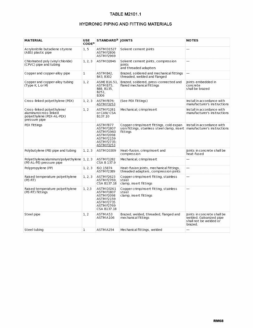
RM68

For SI: °C = [(°F)-32]/1.8.a. Use code:
1. Above ground.2. Embedded in radiant systems.3. Temperatures below 180°F only.4. Low temperature (below 130°F) applications only.5. Temperatures below 160°F only.
b. Standards as listed in Chapter 44.
Reason:ASTM's committee on plastics piping recently completed a new Standard, F3253 - Standard Specification forCrosslinked Polyethylene (PEX) Tubing with Oxygen Barrier for Hot - and Cold - Water Hydronic Distribution Systems. This new system standard covers both the oxygen barrier PEX tubing as well as the performance and materialrequirements for the fittings. While this standard essentially mirrors the existing ASTM F876 and F877 PEX standardsfrom a dimensional standpoint and existing fittings interchangeability, it also mandates the inclusion of an oxygenbarrier layer with defined pass/fail criteria essentially equal with the industry's long accepted norm of DIN 4726concerning allowed oxygen permeation. This new standard also requires a minimum pull-out strength test for thefittings not included in ASTM F877 today. The inclusion of this new standard in no way changes the acceptance of theexisting ASTM F876 and F877 which will remain in the mechanical hydronics code for the foreseeable future.This standard's project has been in works for nearly 4 years and represents the work and input from nearly all of thePEX tubing manufacturers in North America. Your support of this proposal is most appreciated.A similar proposal is being submitted for Chapter 12 of the IMC.Cost ImpactThe code change proposal will not increase or decrease the cost of construction .The addition of this new standard simply offers an alternative product that uses products which are relatively identicalin cost today to existing pipe and fitting materials.Internal ID: 1762
RM69

RM42-18IRC: M2105.7Proponent: Gary Morgan, representing Viega LLC ([email protected])
2018 International Residential Code
M2105.7 Preparation of pipe ends. Pipe shall be cut square , reamed, and shall be free of burrs and obstructions.CPVC, PE and PVC pipe shall be chamfered. Pipe ends shall have full-bore openings and shall not be undercut.beprepared in accordance with the pipe manufacturer's instructions.
Reason:This section is specific to plastic pipes and some of the existing language refers to terms such as "reamed" and"undercut" which only apply to metallic pipes. The revised language is more appropriate by including reference topreparing pipe ends in accordance with manufacturer's instructions which will be specific to that particular type ofplastic pipe.Cost ImpactThe code change proposal will not increase or decrease the cost of construction .This is only a clarification of existing language and will not result in any increased cost of construction.Internal ID: 1829
RM70
RM43-18IRC: M2202.1Proponent: Mark Fasel, Viega, representing Viega LLC ([email protected])
2018 International Residential Code
Revise as follows:
M2202.1 Materials. Piping shall consist of steel pipe, copper and copper-alloy pipe and tubing, steel tubingconforming to ASTM A539 or stainless steel tubing conforming to ASTM A254 or ASTM A539. A269. Aluminum tubing shallnot be used between the fuel-oil tank and the burner units.
Reason:Stainless steel tubing is an accepted material in accordance with NFPA 31 Standard for the Installation of Oil-BurningEquipment section 8.2.2.1 and is widely used in these applications due to its corrosion-resistance.Bibliography:®NFPANFPA 31 Standard for the Installation of Oil-Burning EquipmentSection 8.2.2.12016Page 24http://www.nfpa.org/Cost ImpactThe code change proposal will not increase or decrease the cost of construction .This proposal simply adds stainless steel pipe as an additional piping material that can be used for these applicationsand therefore will not increase the costs of construction.Internal ID: 768
RM71
RM44-18IRC: Chapter 22, M2202.2Proponent: Mark Fasel, representing Viega LLC ([email protected])
2018 International Residential Code
CHAPTER 22 SPECIAL PIPING AND STORAGE SYSTEMS
Revise as follows:
M2202.2 Joints and f ittings. Piping shall be connected with standard fittings compatible with the piping material.Cast-iron fittings shall not be used for oil piping. Unions requiring gaskets or packings, right or left couplings, and sweatfittings employing solder having a melting point less than 1,000°F (538°C) shall not be used for oil piping. Threadedjoints and connections shall be made tight with a lubricant or pipe thread compound. Press-Connect joints shall belisted and labed and shall be installed in accodance with the manufacturer's instructions.
Reason:Press-Connect joints have been tested and listed for use in fuel oil piping systems and are referenced in theInternational Mechanical Code in Chapter 13 Fuel Oil Piping and Storage.Bibliography:UL 180 Standard for Liquid-Level Indicating Gauges for Oil Burner Fuels.Underwriters LaboratoriesPublished 2012 www.ul.comCost ImpactThe code change proposal will not increase or decrease the cost of construction .This standard is not the only standard the pipe fittings can meet in accordance with the Pipe Fittings Table, this is justan alternative standard that some manufacturer’s have tested their products to and would like to see recognized asan acceptable standard for pipe fittings. Testing to this standard is optional and no existing standards have beenremoved or replaced by the proposed addition of this standardInternal ID: 770
RM72

RM45-18IRC: M2202.2Proponent: Mark Fasel, representing Viega LLC ([email protected])
2018 International Residential Code
Revise as follows:
M2202.2 Joints and f ittings. Piping shall be connected with standard fittings compatible with the piping material.Cast-iron fittings shall not be used for oil piping. Unions requiring gaskets or packings, right or left couplings, and sweatfittings employing solder having a melting point less than 1,000°F (538°C) shall not be used for oil piping. Threadedjoints and connections shall be made tight with a lubricant or pipe thread compound.
Reason:Editorial: The term "standard fittings" is not used in any International codes and has no definition. There is no reason tostate the word "standard".Cost ImpactThe code change proposal will not increase or decrease the cost of construction .The removal of the term standard fittings has no cost implications due to the fact this terminology has no requirementsfor listings or required testing associated with this proposal to remove this vague undefined terminology.Internal ID: 861
RM73