ip aquarium system (ipas) - eecs senior design project | the
TRANSCRIPT

1
IP Aquarium System (IPAS)
EECS 129B Professor Kelfstad
Huy Vo Kyaw Aung
Nadia Nabulsi
March 17, 2008

2
Table of Contents
I. Abstract ........................................................................................................................................... 4
II. Project Description .......................................................................................................................... 5
III. Project components ......................................................................................................................... 6
A. Electrical engineering ................................................................................................................... 7
1. Feeder ..................................................................................................................................... 7
2. Camera control base: ............................................................................................................... 9
3. Temperature Sensor:.............................................................................................................. 10
4. Aquarium Heater ................................................................................................................... 12
5. LED lights ............................................................................................................................... 12
B. Software: Webserver design ...................................................................................................... 13
C. Mechanical engineering ............................................................................................................. 15
IV. System test plan ............................................................................................................................ 16
V. Cost analysis .................................................................................................................................. 18
VI. Summary ....................................................................................................................................... 18
VII. Appendix: Software Source Code ................................................................................................... 21
3
Table of Illustration
Figure 1. Block Diagram for IP Aquarium System ...................................................5
Figure 2. System level block diagram ..................................................................... 6
Figure 3. Dual H-Bridges IC NS75441ONE ............................................................... 7
Figure 4. Fish feeder (top view) .............................................................................. 8
Figure 5. Fish feeder (side view) ............................................................................. 8
Figure 6. Camera Control Base ............................................................................... 9
Figure 7. Temperature sensor .............................................................................. 11
Figure 8. LED lighting system ............................................................................... 12
Figure 9. Request handling................................................................................... 14
Picture 1. Fish Feeder..............................................................................................9
Picture 2. Camera Control Base ............................................................................ 10
Picture 3. Temperature sensor and heater ........................................................... 11
Picture 4. Lighting system ..................................................................................... 13

4
I. Abstract
The goal of this project is to build a device that is connected to a web server so we can
monitor it and control it over the internet from anywhere in the world. The basic function of
this device is video streaming. It helps us to monitor for example, a dog or a baby; it can be
anything we want to monitor. Also, the camera can be commanded to move left or right using
an interface in our computer. Moreover, we have a set of switches that is used to get control
over some additional module, i.e. feeding system, lighting system, etc. In this project, we want
to apply the device to monitor and control an aquarium. We would like to monitor the fish with
the video streaming function. The camera we use can be commanded to change its view in
order to get the best view of the aquarium. In addition, we have a feeding system and lighting
system. Also, we have a heater that automatically turns on when the temperature goes below
the minimum allowed temperature and turns off above the maximum temperature.
5
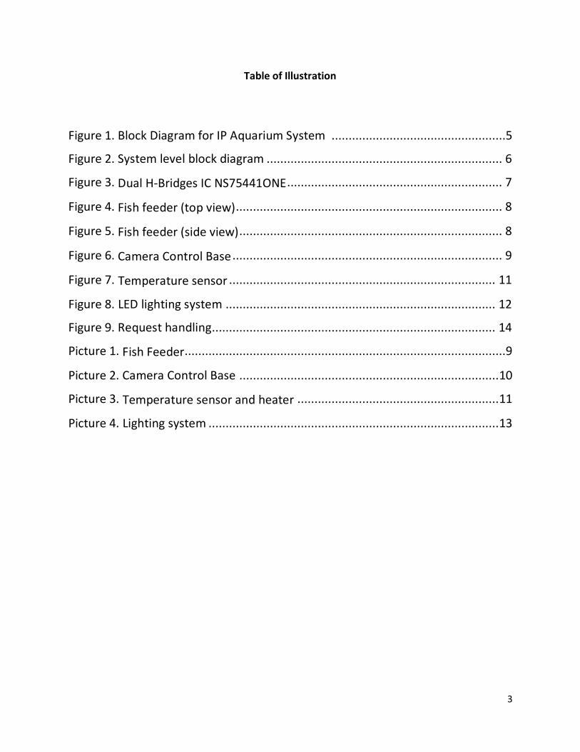
II. Project Description
Figure 1. Block Diagram for IP Aquarium System
The remote user communicates with the server pc through internet for the ability to
send a command, get the web cam streamed data, adjust light intensity and receive
temperature information.
The Aquarium Sensor and Control System consists of an Arduino microcontroller that
interfaces serially with the server PC, and numerous sensors and relays to control and monitor
the system.
The web cam is the only component that is not controlled by the Arduino and is directly
connected to a USB port on the server PC. A streaming server will capture continuous image
from the webcam and stream it to our website.

6
III. Project components
Figure 2. System level block diagram

7
A. Electrical engineering
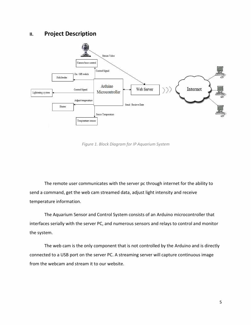
1. Feeder
A 12V operating bipolar motor is used for fish feeder. The feeder has 20 sections and it rotates
and drops a dose of food according to the control as shown in the figure. In order to control the bipolar,
NS75441ONE H-Bridges buffer is used. The detailed wiring for the motor can be seen in circuit level
diagram. As shown in the figure, Vcc1, pin1, and pin9 gets 5V each and Vcc2 gets 12V for the motor.
Pin3,7,11, and 14 are connected to Arduino and get the control signal. The bipolar motor operates
according to the following truth table.
M1A M1B M2A M2B
1 0 1 0 Step 1
0 0 1 0 Step 2
0 1 0 1 Step 3
1 0 0 1 Step 4
Figure 3. Dual H-Bridges IC NS75441ONE
8
Figure 4. Fish feeder (top view)
Figure 5. Fish feeder (side view)
9
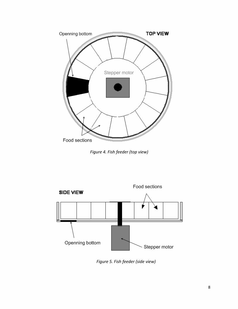
Picture 1.Fish Feeder
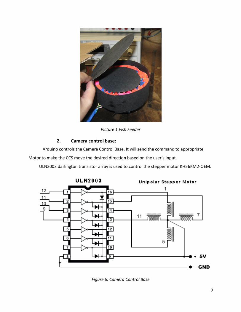
2. Camera control base:
Arduino controls the Camera Control Base. It will send the command to appropriate
Motor to make the CCS move the desired direction based on the user’s input.
ULN2003 darlington transistor array is used to control the stepper motor KH56KM2-OEM.
Figure 6. Camera Control Base

10
Picture 2. Camera Control Base
3. Temperature Sensor:
For measuring temperature of the Aquarium, NTC thermostat (analog temperature
sensor) is used. The sensor is connected according to the figure below.

11
Figure 7. Temperature sensor
The reading that we get from the sensor is the voltage across the sensor in a scale from
0-1024 for 0 being the minimum voltage 0 V, and 1024 the maximum voltage which is 5 V.
Voltage across thermostat = (reading*5/1024) then we calculate the current through the
1Kohm resistor and we use these values we can calculate the temperature according to this
equation to get the temperature in Celsius :
temperature= (4100/Math.log((int)(thermositer resistor)) + 4.1352)- 273
Picture 3. Temperature sensor and heater
12
4. Aquarium Heater
“Aquatic Gardens Profile” aquarium heater is used for adjusting the right temperature
to aquarium. The heater is plugged into the AC power source and a “solid state relay” (SSR) is
used to control to turn on and off the AC power source (120VAC). SSR is used for controlling
high voltage source with lower voltage source. For example, our Arduino digital output can only
output 5V impulse control signal. SSR takes the low 5V control signal to turn on and off the AC
current in order to control the heater. Our SSR has 3V~25V of input and 24V~280V (AC) on
output side. According to the temperature reading, Arduino sends the command to turn on and
off the circuit. In our case, the temperature range is 18 degree Celsius to 24 degree Celsius. If
the temperature goes down under 18 degree, Arduino will send the signal to turn on though
SSR and if the temperature goes above 24 degree, it will send the signal to turn off.
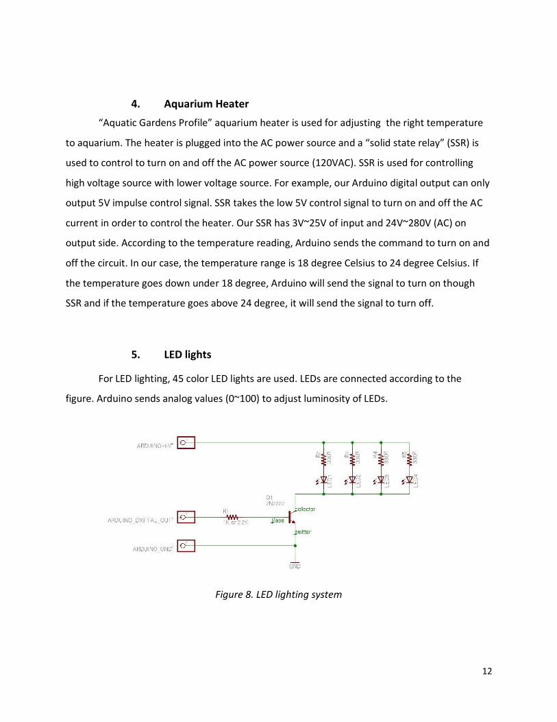
5. LED lights
For LED lighting, 45 color LED lights are used. LEDs are connected according to the
figure. Arduino sends analog values (0~100) to adjust luminosity of LEDs.
Figure 8. LED lighting system

13
Picture 4. Lighting system
B. Software: Webserver design
The system needs a way in order to interact with user. We setup a website with a simple
interface with the following objects:
• Video streaming object.
• Camera control buttons: left/right.
• Feeder buttons: feed/reset feeder
• Light control input text.
• Temperature button.
The first thing we encounter when building the system is how to monitor the aquarium
through internet. We use developed software called WebcamXP in order to setup a streaming
server on port 7070. We choose to use java applet as a streaming object and put the object to
our website. The streaming server keeps feeding video to our streaming object on the website
at the client’s web browser.
Next, we use AJAX to hander user request without refreshing page to avoid interrupting
the video streaming. AJAX is applied with all user-submit objects which are camera control

14
buttons, feeder button, light control input, and temperature button. When a user send a
request, the server receives it through XMLHttpRequest object which accept the submission
without interrupting the video streaming. Then, the server call an appropriate javascript
function to send the GET request to PHP server-script. The PHP will store the request on a file
on the server and send the response message to user.
Processing is an integrated (IDE) development environment tool that is used to read
requests from a file which contains the user requests on the server then send the requests to
the Arduino through serial port.
Firmata is an Arduino code which resides inside the Arduino and acts as a firmware of
the Arduino, so that the Arduino can be treated as a serial device. Firmata processes the signal
sent to it through serial port then output the command signal to the Arduino’s pins. This
approach allows us to control Arduino from host software (Proessing in our case).
The software control can be
PHP, AJAX,
HTTPProcessing
Web Service
Arduino firmware:
Firmata
Microcontroller
3Com
Serial Interface
Aquarium
3 Layers of Request Handling
Figure 9. Request handling

15
C. Mechanical engineering
We use a unipolar stepper motor to control the Camera Control Station (CCS) where we
have the webcam mounted to it. The purpose of the Stepper Motor is used to move left and
right. The webcam mounted into the CCS so that we can control the view angle of the fish-tank.
The camera control base rotation is limited from -90 degree to +90 degree.
The feeding module contains of a rotating wheel which is divided into 20 small sections.
A bipolar stepper motor is used to rotate each section. Each section contains one dose of food.
When we press the “feeding” button, the wheel is going to rotate for 1 section. As a result, 1
dose of food is dropped into the tank.

16
IV. System test plan
Test
Number
Description of Set-
up
Input or Stimulus Expected Behavior
1 Streaming video (all
condition)
Login to web-control
website
Able to see a video which is
monitoring the aquarium on
website
2 Control the camera
(normal)
Click on “left/right”
control button on the
website
The camera moves based on what
button we pushed. However, we
limit the moving to 180 degree.
3 Out of bound
control (critical
condition)
Move the camera left
at its maximum left
angle.
The camera will not be moved left
but can still be moved right.
4 Feeding (normal) Click “feed” button on
the website
The feeding module drops one dose
of food to the fish tank
5 Feeding (out of
food)
Click “feed” button on
the website
A warning message window will
pop up. No movement of the
feeder.

17
Test
Number
Description of Set-
up
Input or Stimulus Expected Behavior
6 Heat up cold water Input ice cubes in the
tank to cool it down
below low-temp
The heater will maintain the
temperature between low-temp
and hi-temp
The heater will turn on until it
reaches to the desired temperature
which we set up on the website.
Then, the heater will turn off.
7 Overheat prevent Heat up the
temperature above
The heater will automatically turn
off when the water temperature is
heated above the hi-temp.
8 Temperature
display
Look at temperature on
the website
View the temperature on the
temperature
9 LED light Adjust the light
intensity by entering
number between 0-100
See light gets brighter and dimmer
according to the value you enter.
10 Internet
communication
Set up a connection
from our system to the
internet.
The server can communicate with
all the sensors. It can read input
and produce output. Press the
button to feed fish.

18
V. Cost analysis
Part Number of Units Total Cost
Arduino USB board
(Microcontroller)
1 $34.95
Webcam 1 $25
MOTOR,DC 1 $17
Fish feeding module 1 $20
Water Heater 1 $14
NTC heat sensor 1 Free
LED lights 32 Free
Total cost of project: $110.95
VI. Summary
Overall, we finished our project with success. While working with our project, we gain a
lot of experience in building an actual system. We can apply our knowledge in circuit design and
web programming to make the system. Throughout the course, we have learned many
concepts to apply in building this system such as stepper motor, temperature, relay control,
video streaming, Processing or AJAX programming.

19
Unfortunately, we didn’t finish our original proposed project which was to use a wireless
embedded server module, Lantronix MatchPort® b/g. We faced many technical difficulties with
the Wi-Fi module we chose. The wireless embedded module did not work with Windows Vista.
After many tries, we decided to use a PC Windows XP. The device was able to receive signal
from Arduino but wasn't sending any signals. We contacted the company and they promised to
send some application notes but they never did. In addition, the device is lack of useful
information in applying in an embedded system. Therefore, we switched to plan B where we
replace the wireless module with a PC server.
On video streaming side, we first thought about using an image sensor to recognize
image, capture it and send it through the Wi-Fi module; however, to make the image sensor to
process the captured images and stream it over the the Wi-Fi module is very challenging and
time consuming process. Therefore, we decided to switch to an USB Webcam for streaming
video.
Another problem we encountered is about the web server-to-serial. We need to design
a website for user to login and controlling the device. The problem we have is about sending
the command of user to the serial device. This is solved by treating Arduino as a serial device
and use Processing IDE to send the serial signal to it. Also, we have a small conflict between
digital temperature sensor with Processing IDE so we switch to analog sensor and the problem
is solved.
This project can be applied to any monitoring and controlling system. With the ability to
control a microcontroller from a website, we can easily implement to monitoring a baby, pet, or
senior or controlling home laundry, cooking, or anything. We can also improve the server side
to do more automating or scheduling task such as automatic temperature adjust, or scheduling
feeding. Nevertheless, we had accomplished our goal that our system can control the aquarium
system through internet.

20
References
http://www.jameco.com/Jameco/Products/ProdDS/207028.pdf
http://www.kronosrobotics.com/an106/DAN106.shtml
http://www.engr.panam.edu/~hvasquez/Mechatronics/Lab%205_DC_motor_control_and
_H_bridges_Fall%202007.pdf
http://www.arduino.cc/playground/uploads/Learning/multiple_leds2.jpg
http://interactive.usc.edu/members/phoberman/archives/007581.html

21
VII. Appendix: Software Source Code
Server code: index.php <script type="text/javascript" language="javascript"> var http_request = false; function makeRequest(url, parameters) { http_request = false; if (window.XMLHttpRequest) { // Mozilla, Safari,... http_request = new XMLHttpRequest(); if (http_request.overrideMimeType) { // set type accordingly to anticipated content type //http_request.overrideMimeType('text/xml'); http_request.overrideMimeType('text/html'); } } else if (window.ActiveXObject) { // IE try { http_request = new ActiveXObject("Msxml2.XMLHTTP"); } catch (e) { try { http_request = new ActiveXObject("Microsoft.XMLHTTP"); } catch (e) {} } } if (!http_request) { alert('Cannot create XMLHTTP instance'); return false; } http_request.onreadystatechange = alertContents; http_request.open('GET', url + parameters, true); http_request.send(null); } function alertContents() { if (http_request.readyState == 4) { if (http_request.status == 200) { //alert(http_request.responseText); result = http_request.responseText; document.getElementById('myspan').innerHTML = result; } else { alert('There was a problem with the request.'); } } } function tempRequest(url, parameters){ http_request = false; if (window.XMLHttpRequest) { // Mozilla, Safari,...

22
http_request = new XMLHttpRequest(); if (http_request.overrideMimeType) { // set type accordingly to anticipated content type //http_request.overrideMimeType('text/xml'); http_request.overrideMimeType('text/html'); } } else if (window.ActiveXObject) { // IE try { http_request = new ActiveXObject("Msxml2.XMLHTTP"); } catch (e) { try { http_request = new ActiveXObject("Microsoft.XMLHTTP"); } catch (e) {} } } if (!http_request) { alert('Cannot create XMLHTTP instance'); return false; } http_request.onreadystatechange = tempAlert; http_request.open('GET', url + parameters, true); http_request.send(null); } function tempAlert(){ if (http_request.readyState == 4) { if (http_request.status == 200) { //alert(http_request.responseText); result = http_request.responseText; document.getElementById('mytemp').innerHTML = result; } else { alert('There was a problem with the request.'); } } } function get(obj) { var getstr = "?"; for (i=0; i<obj.childNodes.length; i++) { if (obj.childNodes[i].tagName == "INPUT") { if (obj.childNodes[i].type == "text") { getstr += obj.childNodes[i].name + "=" + obj.childNodes[i].value + "&"; } } if (obj.childNodes[i].tagName == "SELECT") { var sel = obj.childNodes[i]; getstr += sel.name + "=" + sel.options[sel.selectedIndex].value + "&"; } } makeRequest('get.php', getstr);
23
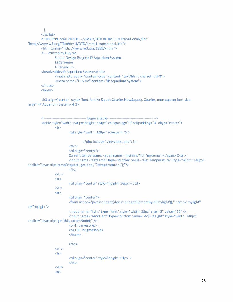
} </script> <!DOCTYPE html PUBLIC "-//W3C//DTD XHTML 1.0 Transitional//EN"
"http://www.w3.org/TR/xhtml1/DTD/xhtml1-transitional.dtd"> <html xmlns="http://www.w3.org/1999/xhtml"> <!-- Written by Huy Vo Senior Design Project: IP Aquarium System EECS Senior UC Irvine --> <head><title>IP Aquarium System</title> <meta http-equiv="content-type" content="text/html; charset=utf-8"> <meta name="Huy Vo" content="IP Aquarium System"> </head> <body> <h3 align="center" style="font-family: "Courier New", Courier, monospace; font-size:
large">IP Aquarium System</h3> <!------------------------------------ begin a table--------------------------------------- --> <table style="width: 640px; height: 254px" cellspacing="0" cellpadding="0" align="center"> <tr> <td style="width: 320px" rowspan="5"> <?php include "viewvideo.php"; ?> </td> <td align="center"> Current temperature: <span name="mytemp" id="mytemp"></span> C<br> <input name="getTemp" type="button" value="Get Temperature" style="width: 140px"
onclick="javascript:tempRequest('get.php', '?temperature=1');"/> </td> </tr> <tr> <td align="center" style="height: 26px"></td> </tr> <tr> <td align="center"> <form action="javascript:get(document.getElementById('mylight'));" name="mylight"
id="mylight"> <input name="light" type="text" style="width: 28px" size="2" value="50" /> <input name="sendLight" type="button" value="Adjust Light" style="width: 140px"
onclick="javascript:get(this.parentNode);" /> <p>1: darkest</p> <p>100: brightest</p> </form> </td> </tr> <tr> <td align="center" style="height: 61px"> </td> </tr> <tr>

24
<td align="center"> <input type="button" name="button" value="Feed Fish" style="height: 61px; width:
156px" onclick="javascript:makeRequest('get.php', '?feeder=1');"> </td> </tr> <tr> <td style="width: 320px"> <input name="moveLeft" type="button" value="Move Left" style="width: 150px"
onclick="javascript:makeRequest('get.php', '?movecam=left');"/> <input name="moveRight" type="button" value="Move Right" style="width: 150px"
onclick="javascript:makeRequest('get.php', '?movecam=right');"/> </td> <td align="center"><input type="button" name="button" value="Reset Feeder" onclick="javascript:makeRequest('get.php', '?resetfeeder=1');"> </td> </tr> </table> <!------------------------------------ end of the table--------------------------------------- --> <br><br> <table align ="center"> <tr> <td align="center"> <br><br> Server-Response:<br> <span name="myspan" id="myspan"></span> </td> </tr> <tr> <td align="center"> <input name="initialreset" type="button" value="Initialize Server" style="width: 140px"
onclick="javascript:makeRequest('get.php', '?initialreset=1');"/> </td> </tr> </table> </body> </html>

25
config.php change this file setup for different server <?php $serverIP = "128.195.223.240"; $sourcepath = "processing\\"; $initialcam = 0; $initialfeeder = 20; $initiallight = 50; $tempfile = $sourcepath."temp.dat"; $lightfile = $sourcepath."light.dat"; $camerafile = $sourcepath."camera.dat"; $feederfile = $sourcepath."feeder.dat"; $feedersize = "20"; $camerastep = "5.4"; $cameramax = 15; $cameramin = -15; ?>
26
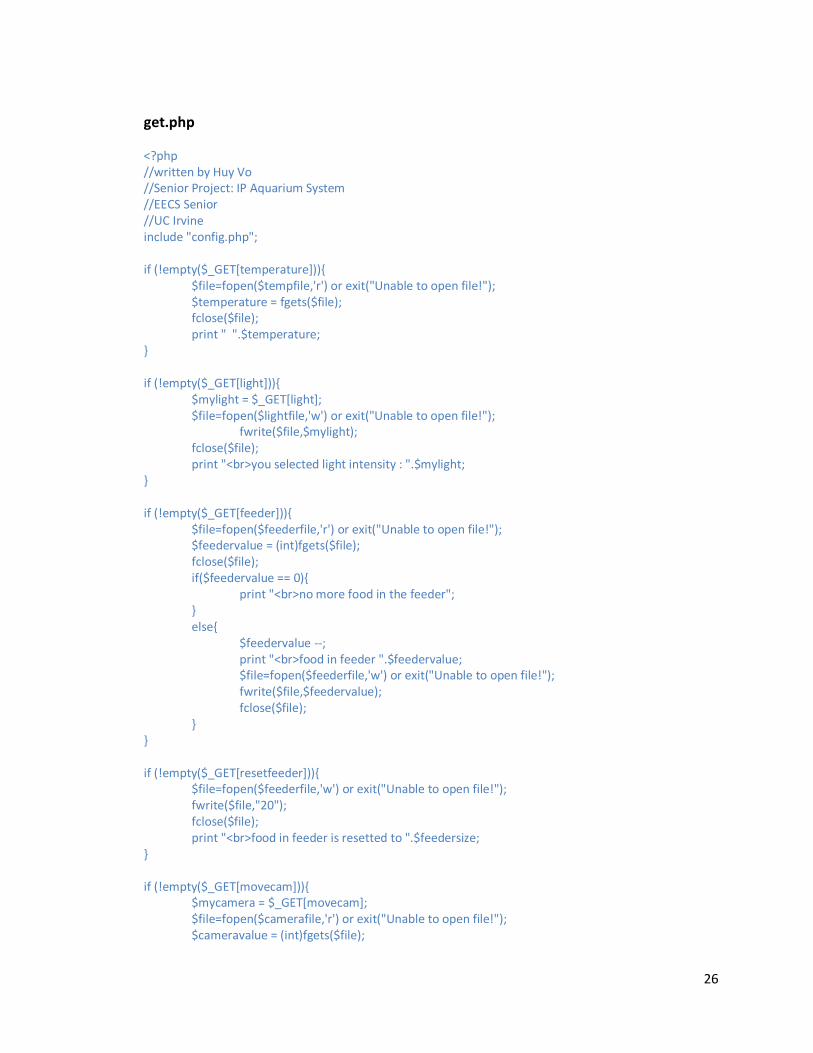
get.php <?php //written by Huy Vo //Senior Project: IP Aquarium System //EECS Senior //UC Irvine include "config.php"; if (!empty($_GET[temperature])){ $file=fopen($tempfile,'r') or exit("Unable to open file!"); $temperature = fgets($file); fclose($file); print " ".$temperature; } if (!empty($_GET[light])){ $mylight = $_GET[light]; $file=fopen($lightfile,'w') or exit("Unable to open file!"); fwrite($file,$mylight); fclose($file); print "<br>you selected light intensity : ".$mylight; } if (!empty($_GET[feeder])){ $file=fopen($feederfile,'r') or exit("Unable to open file!"); $feedervalue = (int)fgets($file); fclose($file); if($feedervalue == 0){ print "<br>no more food in the feeder"; } else{ $feedervalue --; print "<br>food in feeder ".$feedervalue; $file=fopen($feederfile,'w') or exit("Unable to open file!"); fwrite($file,$feedervalue); fclose($file); } } if (!empty($_GET[resetfeeder])){ $file=fopen($feederfile,'w') or exit("Unable to open file!"); fwrite($file,"20"); fclose($file); print "<br>food in feeder is resetted to ".$feedersize; } if (!empty($_GET[movecam])){ $mycamera = $_GET[movecam]; $file=fopen($camerafile,'r') or exit("Unable to open file!"); $cameravalue = (int)fgets($file);

27
fclose($file); if($mycamera == "left"){ if($cameravalue==$cameramin){ print "<br>camera can not move left anymore"; } else{ $cameravalue--; $file=fopen($camerafile,'w') or exit("Unable to open file!"); fwrite($file,$cameravalue); fclose($file); print "<br>camera is moving ".$mycamera; print "<br>current value (-17 to 17): ".$cameravalue; } } else if($mycamera == "right"){ if($cameravalue==$cameramax){ print "<br>camera can not move right anymore"; } else{ $cameravalue++; $file=fopen($camerafile,'w') or exit("Unable to open file!"); fwrite($file,$cameravalue); fclose($file); print "<br>camera is moving ".$mycamera; print "<br>current value (-15 to 15): ".$cameravalue; } } else{ print "<br>invalid!!!!"; } } if (!empty($_GET[initialreset])){ print "<br>Initiallizing the server"; $file=fopen($camerafile,'w') or exit("Unable to open file!"); fwrite($file,$initialcam); fclose($file); $file=fopen($lightfile,'w') or exit("Unable to open file!"); fwrite($file,$initiallight); fclose($file); $file=fopen($feederfile,'w') or exit("Unable to open file!"); fwrite($file,$initialfeeder); fclose($file); } ?>

28
viewvideo.php <?php //written by Huy Vo //Senior Project: IP Aquarium System //EECS Senior //UC Irvine include "config.php"; //the following code is used to put a video streaming object to our website. //In this case, i use WebcamXp with javaapplet as a object print '<applet codebase="http://'.$serverIP.':7070/" code="mJPEG.class" archive="streaming.jar"
id="webcamXP" width="320" height="240" hspace="0" vspace="0" align="top" refresh="70" filename="cam_6.mjpg"></applet>';
?>
ajaxrequest.js var http_request = false; function makeRequest(url, parameters) { http_request = false; if (window.XMLHttpRequest) { // Mozilla, Safari,... http_request = new XMLHttpRequest(); if (http_request.overrideMimeType) { // set type accordingly to anticipated content type //http_request.overrideMimeType('text/xml'); http_request.overrideMimeType('text/html'); } } else if (window.ActiveXObject) { // IE try { http_request = new ActiveXObject("Msxml2.XMLHTTP"); } catch (e) { try { http_request = new ActiveXObject("Microsoft.XMLHTTP"); } catch (e) {} } } if (!http_request) { alert('Cannot create XMLHTTP instance'); return false; } http_request.onreadystatechange = alertContents; http_request.open('GET', url + parameters, true); http_request.send(null); } function alertContents() { if (http_request.readyState == 4) {
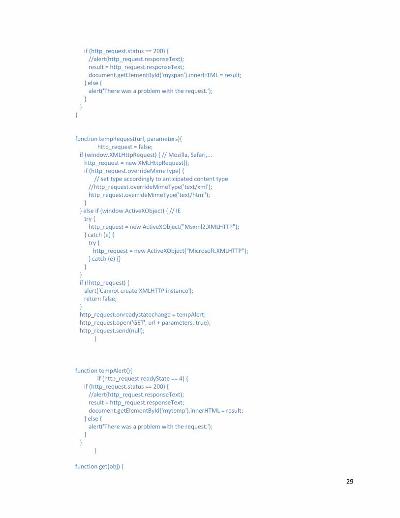
29
if (http_request.status == 200) { //alert(http_request.responseText); result = http_request.responseText; document.getElementById('myspan').innerHTML = result; } else { alert('There was a problem with the request.'); } } } function tempRequest(url, parameters){ http_request = false; if (window.XMLHttpRequest) { // Mozilla, Safari,... http_request = new XMLHttpRequest(); if (http_request.overrideMimeType) { // set type accordingly to anticipated content type //http_request.overrideMimeType('text/xml'); http_request.overrideMimeType('text/html'); } } else if (window.ActiveXObject) { // IE try { http_request = new ActiveXObject("Msxml2.XMLHTTP"); } catch (e) { try { http_request = new ActiveXObject("Microsoft.XMLHTTP"); } catch (e) {} } } if (!http_request) { alert('Cannot create XMLHTTP instance'); return false; } http_request.onreadystatechange = tempAlert; http_request.open('GET', url + parameters, true); http_request.send(null); } function tempAlert(){ if (http_request.readyState == 4) { if (http_request.status == 200) { //alert(http_request.responseText); result = http_request.responseText; document.getElementById('mytemp').innerHTML = result; } else { alert('There was a problem with the request.'); } } } function get(obj) {
30
var getstr = "?"; for (i=0; i<obj.childNodes.length; i++) { if (obj.childNodes[i].tagName == "INPUT") { if (obj.childNodes[i].type == "text") { getstr += obj.childNodes[i].name + "=" + obj.childNodes[i].value + "&"; } } if (obj.childNodes[i].tagName == "SELECT") { var sel = obj.childNodes[i]; getstr += sel.name + "=" + sel.options[sel.selectedIndex].value + "&"; } } makeRequest('get.php', getstr); }
Processing code: ////////////////////////////////////////////////////////////////////////////////// //Written By //Huy Vo - main program and camera control function //Aungk - lighting, feeder and heater functions //Nadia - temperature sensor reading function //IP Aquarium System (iPas) //Computer Engineering Senior Project //UC Irvine ////////////////////////////////////////////////////////////////////////////////// import processing.serial.*; import cc.arduino.*; //server information String serverIP = "128.195.223.240"; String sourcepath = "/arduino/processing/"; String tempfile = "temp.dat"; String lightfile = "light.dat"; String camerafile = "camera.dat"; String feederfile = "feeder.dat"; //pin mode of the arduino Arduino arduino; int camMotorPin1 = 12; int camMotorPin2 = 11; int camMotorPin3 = 10; int camMotorPin4 = 9; int camMotorDelay = 1;
31
int temPin = 2; int ledPin = 3; //pin 4-7 for stepper motor control for feeder int pin1 = 4; int pin2 = 5; int pin3 = 6; int pin4 = 7; int feederDelay = 30; int heaterpin =8; //server use only int maxtemp = 26; int mintemp = 19; int temperature; int light; int oldlight; int lightbright; int cameraposition; int oldcameraposition; int feeder; int oldfeeder; String[] fileinput; void setup() { //reading input initialized in the server folder print("loading file...."); fileinput = loadStrings("http://" + serverIP + sourcepath + tempfile); temperature = Integer.parseInt(fileinput[0]); fileinput = loadStrings("http://" + serverIP + sourcepath + lightfile); oldlight = Integer.parseInt(fileinput[0]); fileinput = loadStrings("http://" + serverIP + sourcepath + camerafile); oldcameraposition = Integer.parseInt(fileinput[0]); fileinput = loadStrings("http://" + serverIP + sourcepath + feederfile); oldfeeder = Integer.parseInt(fileinput[0]); println(" completed."); //Arduino implementation of pin modes println(Arduino.list()); arduino = new Arduino(this, Arduino.list()[1], 57600); //Pin Mode to control camera motor arduino.pinMode(camMotorPin1, Arduino.OUTPUT); arduino.pinMode(camMotorPin2, Arduino.OUTPUT); arduino.pinMode(camMotorPin3, Arduino.OUTPUT); arduino.pinMode(camMotorPin4, Arduino.OUTPUT);
32
//activating all feeder control pins arduino.pinMode(pin1, Arduino.OUTPUT); arduino.pinMode(pin2, Arduino.OUTPUT); arduino.pinMode(pin3, Arduino.OUTPUT); arduino.pinMode(pin4, Arduino.OUTPUT); //activating heater and LED light switch arduino.pinMode(heaterpin,Arduino.OUTPUT); arduino.pinMode(ledPin,Arduino.OUTPUT); arduino.pinMode(temPin,Arduino.INPUT); //Pin Mode for others //need to be filled in by Kevin and Nadia } /////////////////////////////////////////////// Main //running //////////////////////////////////////////////////////////////////////// void draw() { //reading temperature int temp = measureTemp(); String tempStr = temp + ""; println ("current temperature " + tempStr); String savefile[] = {tempStr}; saveStrings(tempfile, savefile); delay(10); //delay for finishing writing file //sending light intensity fileinput = loadStrings("http://" + serverIP + sourcepath + lightfile); for (int i=0; i < fileinput.length; i++) { println("current light intensity " + fileinput[i]); } light = Integer.parseInt(fileinput[0]); if(light != oldlight){ adjustLight(light); oldlight = light; //update the light } delay(10); //sending camera control command fileinput = loadStrings("http://" + serverIP + sourcepath + camerafile); println("current camera position " + oldcameraposition); cameraposition = Integer.parseInt(fileinput[0]); if(cameraposition<oldcameraposition){ camleft(); oldcameraposition--;

33
} else if(cameraposition>oldcameraposition){ camright(); oldcameraposition++; } delay(10); //sending feeder command fileinput = loadStrings("http://" + serverIP + sourcepath + feederfile); println("current number of food in the feeder " + oldfeeder); feeder = Integer.parseInt(fileinput[0]); if(feeder == 20 && oldfeeder != 20){ oldfeeder = 20; println("reset feeder"); } if(feeder<oldfeeder){ feedFish(); oldfeeder--; } delay(10); heatercontrol(); //control the heater with current temperature println("//////////////////////////////////////////////////////////////"); // delay(100); //for testing only, remove this delay when running with arduino } //////////////////////////////////////////////////////////////////// //Additional functions ///////////////////////////// float voltage=0; float val=0; float cur=0; int measureTemp () { voltage =arduino.analogRead(temPin); val = (voltage*5/1024); cur = 5 - val; //voltage at 1 k ohm cur = cur / 1000; //current at through one k ohm val = val / cur; // the thermistor resistance double temp =( (Math.log((int)(val)))) + 4.14258; //ln(Rinf) =-4.1352----> Rinf = 0.015 Ohm temp = 4100/temp; temp = temp - 272; //result in C //heatcontrol((int)temp); println((int)temp); return (int) temp;

34
} void camleft(){ println("moving camera left"); arduino.digitalWrite(camMotorPin1, Arduino.HIGH); arduino.digitalWrite(camMotorPin2, Arduino.LOW); arduino.digitalWrite(camMotorPin3, Arduino.LOW); arduino.digitalWrite(camMotorPin4, Arduino.LOW); delay(camMotorDelay); arduino.digitalWrite(camMotorPin1, Arduino.LOW); arduino.digitalWrite(camMotorPin2, Arduino.LOW); arduino.digitalWrite(camMotorPin3, Arduino.LOW); arduino.digitalWrite(camMotorPin4, Arduino.HIGH); delay(camMotorDelay); arduino.digitalWrite(camMotorPin1, Arduino.LOW); arduino.digitalWrite(camMotorPin2, Arduino.LOW); arduino.digitalWrite(camMotorPin3, Arduino.HIGH); arduino.digitalWrite(camMotorPin4, Arduino.LOW); delay(camMotorDelay); arduino.digitalWrite(camMotorPin1, Arduino.LOW); arduino.digitalWrite(camMotorPin2, Arduino.HIGH); arduino.digitalWrite(camMotorPin3, Arduino.LOW); arduino.digitalWrite(camMotorPin4, Arduino.LOW); delay(camMotorDelay); arduino.digitalWrite(camMotorPin1, Arduino.HIGH); arduino.digitalWrite(camMotorPin2, Arduino.LOW); arduino.digitalWrite(camMotorPin3, Arduino.LOW); arduino.digitalWrite(camMotorPin4, Arduino.LOW); delay(camMotorDelay); } void camright(){ println("moving camera right"); arduino.digitalWrite(camMotorPin1, Arduino.HIGH); arduino.digitalWrite(camMotorPin2, Arduino.LOW); arduino.digitalWrite(camMotorPin3, Arduino.LOW); arduino.digitalWrite(camMotorPin4, Arduino.LOW); delay(camMotorDelay); arduino.digitalWrite(camMotorPin1, Arduino.LOW); arduino.digitalWrite(camMotorPin2, Arduino.HIGH); arduino.digitalWrite(camMotorPin3, Arduino.LOW); arduino.digitalWrite(camMotorPin4, Arduino.LOW); delay(camMotorDelay); arduino.digitalWrite(camMotorPin1, Arduino.LOW); arduino.digitalWrite(camMotorPin2, Arduino.LOW); arduino.digitalWrite(camMotorPin3, Arduino.HIGH); arduino.digitalWrite(camMotorPin4, Arduino.LOW); delay(camMotorDelay); arduino.digitalWrite(camMotorPin1, Arduino.LOW); arduino.digitalWrite(camMotorPin2, Arduino.LOW); arduino.digitalWrite(camMotorPin3, Arduino.LOW); arduino.digitalWrite(camMotorPin4, Arduino.HIGH); delay(camMotorDelay);

35
arduino.digitalWrite(camMotorPin1, Arduino.HIGH); arduino.digitalWrite(camMotorPin2, Arduino.LOW); arduino.digitalWrite(camMotorPin3, Arduino.LOW); arduino.digitalWrite(camMotorPin4, Arduino.LOW); delay(camMotorDelay); } //heater control void heatercontrol() { println("heater control processing..."); if(temperature < mintemp) { turnonheater(); } else if(temperature > maxtemp) { turnoffheater(); } } void turnonheater() { arduino.digitalWrite(heaterpin,Arduino.HIGH); delay(100); } void turnoffheater() { arduino.digitalWrite(heaterpin,Arduino.LOW); delay(100); } void feedFish() { println("feeding fish"); for(int control=0; control <3; control++) { arduino.digitalWrite(pin1, Arduino.HIGH); arduino.digitalWrite(pin2, Arduino.LOW); arduino.digitalWrite(pin3, Arduino.HIGH); arduino.digitalWrite(pin4, Arduino.LOW); delay(feederDelay); arduino.digitalWrite(pin1, Arduino.LOW); arduino.digitalWrite(pin2, Arduino.LOW); arduino.digitalWrite(pin3, Arduino.HIGH); arduino.digitalWrite(pin4, Arduino.LOW); delay(feederDelay); arduino.digitalWrite(pin1, Arduino.LOW); arduino.digitalWrite(pin2, Arduino.HIGH); arduino.digitalWrite(pin3, Arduino.LOW); arduino.digitalWrite(pin4, Arduino.HIGH); delay(feederDelay);

36
arduino.digitalWrite(pin1, Arduino.HIGH); arduino.digitalWrite(pin2, Arduino.LOW); arduino.digitalWrite(pin3, Arduino.LOW); arduino.digitalWrite(pin4, Arduino.HIGH); delay(feederDelay); //counter++; } } void adjustLight(int light){ light = light * 10; println("adjusting lighting system to " + light); if (light<1) { arduino.analogWrite (ledPin, 1); delay (100); } else { arduino.analogWrite (ledPin, light); delay (100); } }
Firmata /* * Copyright (C) 2006 Free Software Foundation * * This program is free software; you can redistribute it and/or * modify it under the terms of the GNU General Public License * as published by the Free Software Foundation; either version 2 * of the License, or (at your option) any later version. * * See file LICENSE for further informations on licensing terms. * * This program is distributed in the hope that it will be useful, * but WITHOUT ANY WARRANTY; without even the implied warranty of * MERCHANTABILITY or FITNESS FOR A PARTICULAR PURPOSE. See the * GNU General Public License for more details. * * You should have received a copy of the GNU General Public License * along with this program; if not, write to the Free Software Foundation, * Inc., 59 Temple Place - Suite 330, Boston, MA 02111-1307, USA. * * ----------------------------------------------------------- * Firmata, the general purpose sensorbox firmware for Arduino * ----------------------------------------------------------- * * Firmata turns the Arduino into a Plug-n-Play sensorbox, servo

37
* controller, and/or PWM motor/lamp controller. * * It was originally designed to work with the Pd object [arduino] * which is included in Pd-extended. This firmware is intended to * work with any host computer software package. It can easily be * used with other programs like Max/MSP, Processing, or whatever can * do serial communications. * * @author: Hans-Christoph Steiner <[email protected]> * help with initial protocol redesign: Jamie Allen <[email protected]> * much protocol discussion: the Arduino developers mailing list * key bugfixes: Georg Holzmann <[email protected]> * Gerda Strobl <[email protected]> * @date: 2006-05-19 * @locations: STEIM, Amsterdam, Netherlands * IDMI/Polytechnic University, Brookyn, NY, USA * Electrolobby Ars Electronica, Linz, Austria */ /* * TODO: add pulseOut functionality for servos * TODO: add software PWM for servos, etc (servo.h or pulse.h) * TODO: add device type reporting (i.e. some firmwares will use the Firmata * protocol, but will only support specific devices, like ultrasound * rangefinders or servos) * TODO: use Program Control to load stored profiles from EEPROM */ /* cvs version: $Id: Pd_firmware.pde,v 1.29 2007/03/08 05:37:22 eighthave Exp $ */ /* svn version: 334 */ /*============================================================================== * MESSAGE FORMATS *============================================================================*/ /* ----------------------------------------------------------------------------- * MAPPING DATA TO MIDI * * This protocol uses the MIDI message format, but does not use the whole * protocol. Most of the command mappings here will not be directly usable in * terms of MIDI controllers and synths. It should co-exist with MIDI without * trouble and can be parsed by standard MIDI interpreters. Just some of the * message data is used differently. * * MIDI format: http://www.harmony-central.com/MIDI/Doc/table1.html * * MIDI * type command channel first byte second byte * ----------------------------------------------------------------------------- * analog I/O 0xE0 pin # LSB(bits 0-6) MSB(bits 7-13) * digital I/O 0x90 port base LSB(bits 0-6) MSB(bits 7-13) * report analog pin 0xC0 pin # disable/enable(0/1) - n/a - * report digital ports 0xD0 port base disable/enable(0/1) - n/a -

38
* * digital pin mode(I/O) 0xF4 - n/a - pin # (0-63) pin state(0=in) * firmware version 0xF9 - n/a - minor version major version * system reset 0xFF - n/a - - n/a - - n/a - * */ /* proposed extensions using SysEx * * type SysEx start command data bytes SysEx stop * ----------------------------------------------------------------------------- * pulse I/O 0xF0 0xA0 five 7-bit chunks, LSB first 0xF7 * shiftOut 0xF0 0xF5 dataPin; clockPin; 7-bit LSB; 7-bit MSB 0xF7 */ /* ----------------------------------------------------------------------------- * DATA MESSAGE FORMAT */ /* two byte digital data format * ---------------------------- * 0 digital data, 0x90-0x9F, (MIDI NoteOn, but different data usage) * 1 digital pins 0-6 bitmask * 2 digital pins 7-13 bitmask */ /* analog 14-bit data format * ------------------------- * 0 analog pin, 0xE0-0xEF, (MIDI Pitch Wheel) * 1 analog least significant 7 bits * 2 analog most significant 7 bits */ /* version report format * Send a single byte 0xF9, Arduino will reply with: * ------------------------------------------------- * 0 version report header (0xF9) (MIDI Undefined) * 1 minor version (0-127) * 2 major version (0-127) */ /* pulseIn/Out (uses 32-bit value) * ------------------------------- * 0 START_SYSEX (0xF0) (MIDI System Exclusive) * 1 pulseIn/Out (0xA0-0xAF) * 2 bits 0-6 (least significant byte) * 3 bits 7-13 * 4 bits 14-20 * 5 bits 21-27 * 6 bits 28-34 (most significant byte) * 7 END_SYSEX (0xF7) (MIDI End of SysEx - EOX) */ /* shiftIn/Out (uses 8-bit value)

39
* ------------------------------ * 0 START_SYSEX (0xF0) * 1 shiftOut (0xF5) * 2 dataPin (0-127) * 3 clockPin (0-127) * 4 bits 0-6 (least significant byte) * 5 bit 7 (most significant bit) * 6 END_SYSEX (0xF7) */ /* ----------------------------------------------------------------------------- * CONTROL MESSAGES */ /* set digital pin mode * -------------------- * 1 set digital pin mode (0xF4) (MIDI Undefined) * 2 pin number (0-127) * 3 state (INPUT/OUTPUT, 0/1) */ /* toggle analogIn reporting by pin * -------------------------------- * 0 toggle digitalIn reporting (0xC0-0xCF) (MIDI Program Change) * 1 disable(0)/enable(non-zero) */ /* toggle digitalIn reporting by port pairs * ---------------------------------------- * 0 toggle digitalIn reporting (0xD0-0xDF) (MIDI Aftertouch) * 1 disable(0)/enable(non-zero) */ /* request version report * ---------------------- * 0 request version report (0xF9) (MIDI Undefined) */ /*============================================================================== * MACROS *============================================================================*/ /* Version numbers for the protocol. The protocol is still changing, so these * version numbers are important. This number can be queried so that host * software can test whether it will be compatible with the currently * installed firmware. */ #define FIRMATA_MAJOR_VERSION 1 // for non-compatible changes #define FIRMATA_MINOR_VERSION 0 // for backwards compatible changes /* total number of pins currently supported */ #define TOTAL_ANALOG_PINS 6 #define TOTAL_DIGITAL_PINS 14 // for comparing along with INPUT and OUTPUT
40
#define PWM 2 // for selecting digital inputs #define PB 2 // digital input, pins 8-13 #define PC 3 // analog input port #define PD 4 // digital input, pins 0-7 #define MAX_DATA_BYTES 2 // max number of data bytes in non-SysEx messages /* message command bytes */ #define DIGITAL_MESSAGE 0x90 // send data for a digital pin #define ANALOG_MESSAGE 0xE0 // send data for an analog pin (or PWM) //#define PULSE_MESSAGE 0xA0 // proposed pulseIn/Out message (SysEx) //#define SHIFTOUT_MESSAGE 0xB0 // proposed shiftOut message (SysEx) #define REPORT_ANALOG_PIN 0xC0 // enable analog input by pin # #define REPORT_DIGITAL_PORTS 0xD0 // enable digital input by port pair #define START_SYSEX 0xF0 // start a MIDI SysEx message #define SET_DIGITAL_PIN_MODE 0xF4 // set a digital pin to INPUT or OUTPUT #define END_SYSEX 0xF7 // end a MIDI SysEx message #define REPORT_VERSION 0xF9 // report firmware version #define SYSTEM_RESET 0xFF // reset from MIDI /*============================================================================== * GLOBAL VARIABLES *============================================================================*/ /* input message handling */ byte waitForData = 0; // this flag says the next serial input will be data byte executeMultiByteCommand = 0; // execute this after getting multi-byte data byte multiByteChannel = 0; // channel data for multiByteCommands byte storedInputData[MAX_DATA_BYTES] = {0,0}; // multi-byte data /* digital pins */ boolean digitalInputsEnabled = false; // output digital inputs or not int digitalInputs; int previousDigitalInputs; // previous output to test for change int digitalPinStatus = 3; // bitwise array to store pin status, ignore RxTx pins /* PWM/analog outputs */ int pwmStatus = 0; // bitwise array to store PWM status /* analog inputs */ unsigned int analogPinsToReport = 0; // bitwise array to store pin reporting int analogPin = 0; // counter for reading analog pins int analogData; // storage variable for data from analogRead() /* timer variables */ extern volatile unsigned long timer0_overflow_count; // timer0 from wiring.c unsigned long nextExecuteTime; // for comparison with timer0_overflow_count /*============================================================================== * FUNCTIONS *============================================================================*/ /* ----------------------------------------------------------------------------- * output the version message to the serial port */ void printVersion() { Serial.print(REPORT_VERSION, BYTE); Serial.print(FIRMATA_MINOR_VERSION, BYTE);

41
Serial.print(FIRMATA_MAJOR_VERSION, BYTE); } /* ----------------------------------------------------------------------------- * output digital bytes received from the serial port */ void outputDigitalBytes(byte pin0_6, byte pin7_13) { int i; int mask; int twoBytesForPorts; // this should be converted to use PORTs twoBytesForPorts = pin0_6 + (pin7_13 << 7); for(i=2; i<TOTAL_DIGITAL_PINS; ++i) { // ignore Rx,Tx pins (0 and 1) mask = 1 << i; if( (digitalPinStatus & mask) && !(pwmStatus & mask) ) { digitalWrite(i, twoBytesForPorts & mask ? HIGH : LOW); } } } /* ----------------------------------------------------------------------------- * check all the active digital inputs for change of state, then add any events * to the Serial output queue using Serial.print() */ void checkDigitalInputs(void) { if(digitalInputsEnabled) { previousDigitalInputs = digitalInputs; digitalInputs = PINB << 8; // get pins 8-13 digitalInputs += PIND; // get pins 0-7 digitalInputs = digitalInputs &~ digitalPinStatus; // ignore pins set OUTPUT if(digitalInputs != previousDigitalInputs) { // TODO: implement more ports as channels for more than 16 digital pins Serial.print(DIGITAL_MESSAGE,BYTE); Serial.print(digitalInputs % 128, BYTE); // Tx pins 0-6 Serial.print(digitalInputs >> 7, BYTE); // Tx pins 7-13 } } } // ----------------------------------------------------------------------------- /* sets the pin mode to the correct state and sets the relevant bits in the * two bit-arrays that track Digital I/O and PWM status */ void setPinMode(byte pin, byte mode) { if(pin > 1) { // ignore RxTx pins (0,1) if(mode == INPUT) { digitalPinStatus = digitalPinStatus &~ (1 << pin); pwmStatus = pwmStatus &~ (1 << pin); digitalWrite(pin,LOW); // turn off pin before switching to INPUT pinMode(pin,INPUT); } else if(mode == OUTPUT) { digitalPinStatus = digitalPinStatus | (1 << pin); pwmStatus = pwmStatus &~ (1 << pin);

42
pinMode(pin,OUTPUT); } else if( mode == PWM ) { digitalPinStatus = digitalPinStatus | (1 << pin); pwmStatus = pwmStatus | (1 << pin); pinMode(pin,OUTPUT); } // TODO: save status to EEPROM here, if changed } } // ----------------------------------------------------------------------------- /* sets bits in a bit array (int) to toggle the reporting of the analogIns */ void setAnalogPinReporting(byte pin, byte state) { if(state == 0) { analogPinsToReport = analogPinsToReport &~ (1 << pin); } else { // everything but 0 enables reporting of that pin analogPinsToReport = analogPinsToReport | (1 << pin); } // TODO: save status to EEPROM here, if changed } /* ----------------------------------------------------------------------------- * processInput() is called whenever a byte is available on the * Arduino's serial port. This is where the commands are handled. */ void processInput(int inputData) { int command; // a few commands have byte(s) of data following the command if( (waitForData > 0) && (inputData < 128) ) { waitForData--; storedInputData[waitForData] = inputData; if( (waitForData==0) && executeMultiByteCommand ) { // got the whole message switch(executeMultiByteCommand) { case ANALOG_MESSAGE: setPinMode(multiByteChannel,PWM); analogWrite(multiByteChannel, (storedInputData[0] << 7) + storedInputData[1] ); break; case DIGITAL_MESSAGE: outputDigitalBytes(storedInputData[1], storedInputData[0]); //(LSB, MSB) break; case SET_DIGITAL_PIN_MODE: setPinMode(storedInputData[1], storedInputData[0]); // (pin#, mode) if(storedInputData[0] == INPUT) digitalInputsEnabled = true; // enable reporting of digital inputs break; case REPORT_ANALOG_PIN: setAnalogPinReporting(multiByteChannel,storedInputData[0]); break; case REPORT_DIGITAL_PORTS:

43
// TODO: implement MIDI channel as port base for more than 16 digital inputs if(storedInputData[0] == 0) digitalInputsEnabled = false; else digitalInputsEnabled = true; break; } executeMultiByteCommand = 0; } } else { // remove channel info from command byte if less than 0xF0 if(inputData < 0xF0) { command = inputData & 0xF0; multiByteChannel = inputData & 0x0F; } else { command = inputData; // commands in the 0xF* range don't use channel data } switch (command) { // TODO: these needs to be switched to command case ANALOG_MESSAGE: case DIGITAL_MESSAGE: case SET_DIGITAL_PIN_MODE: waitForData = 2; // two data bytes needed executeMultiByteCommand = command; break; case REPORT_ANALOG_PIN: case REPORT_DIGITAL_PORTS: waitForData = 1; // two data bytes needed executeMultiByteCommand = command; break; case SYSTEM_RESET: // this doesn't do anything yet break; case REPORT_VERSION: printVersion(); break; } } } /* ----------------------------------------------------------------------------- * this function checks to see if there is data waiting on the serial port * then processes all of the stored data */ void checkForSerialReceive() { while(Serial.available()) processInput(Serial.read()); } // ============================================================================= // used for flashing the pin for the version number void pin13strobe(int count, int onInterval, int offInterval) { byte i;

44
pinMode(13, OUTPUT); for(i=0; i<count; i++) { delay(offInterval); digitalWrite(13,1); delay(onInterval); digitalWrite(13,0); } } /*============================================================================== * SETUP() *============================================================================*/ void setup() { byte i; Serial.begin(57600); // 9600, 14400, 38400, 57600, 115200 // flash the pin 13 with the protocol version pinMode(13,OUTPUT); pin13strobe(2,1,4); // separator, a quick burst delay(500); pin13strobe(FIRMATA_MAJOR_VERSION, 200, 400); delay(500); pin13strobe(2,1,4); // separator, a quick burst delay(500); pin13strobe(FIRMATA_MINOR_VERSION, 200, 400); delay(500); pin13strobe(2,1,4); // separator, a quick burst for(i=0; i<TOTAL_DIGITAL_PINS; ++i) { setPinMode(i,INPUT); } // TODO: load state from EEPROM here printVersion(); /* TODO: send digital inputs here, if enabled, to set the initial state on the * host computer, since once in the loop(), the Arduino will only send data on * change. */ } /*============================================================================== * LOOP() *============================================================================*/ void loop() { /* DIGITALREAD - as fast as possible, check for changes and output them to the * FTDI buffer using Serial.print() */ checkDigitalInputs(); if(timer0_overflow_count > nextExecuteTime) { nextExecuteTime = timer0_overflow_count + 19; // run this every 20ms /* SERIALREAD - Serial.read() uses a 128 byte circular buffer, so handle * all serialReads at once, i.e. empty the buffer */ checkForSerialReceive();

45
/* SEND FTDI WRITE BUFFER - make sure that the FTDI buffer doesn't go over * 60 bytes. use a timer to sending an event character every 4 ms to * trigger the buffer to dump. */ /* ANALOGREAD - right after the event character, do all of the * analogReads(). These only need to be done every 4ms. */ for(analogPin=0;analogPin<TOTAL_ANALOG_PINS;analogPin++) { if( analogPinsToReport & (1 << analogPin) ) { analogData = analogRead(analogPin); Serial.print(ANALOG_MESSAGE + analogPin, BYTE); // These two bytes converted back into the 10-bit value on host Serial.print(analogData % 128, BYTE); Serial.print(analogData >> 7, BYTE); } } } }