iot poly engineering 2-10 a in the right view of the drawing below (prp), point a is 2’-3” away...
TRANSCRIPT

IOT
POLY ENGINEERING2-10
A
• In the right view of the drawing below (PRP), point A is 2’-3” away from the frontal reference plane.1. In the top view drawing, how far will point A be from
the frontal reference plane?2. In the front view drawing, how far will point A be from
the frontal reference plane?
Com
mun
icati
on T
echn
olog
y
DRILLNovember 3, 2010
1) 2’-3”
2) 2’-3”
If point A is 2’-3” away from the FRP in the right view, point A will ALWAYS be 2’-3” away from the FRP.

• Cover the 3 main technical drawing types and their ~12 variations
• Establish class standards for technical drawing• Further develop and apply skills in drafting• Develop and apply skills in Google Sketchup
IOT
POLY ENGINEERING2-9
Objectives
Tech
nica
l Gra
phic
Com
mun
icati
onThe remainder of Unit 2:
Technical Graphic Communication

• One of many drafting techniques• Quick way to show an idea that would be difficult
to describe with words alone• Used mainly in Engineering Design Process Step 2:
Brainstorm, Research, and Generate Ideas
• NO DRAWING TOOLS (not even a straightedge)• Rules of drawing STILL APPLY
– Pull, don’t push– LIGHT construction lines– Use appropriate line weight and type
IOT
POLY ENGINEERING2-9
SKETCHESTY
PE 1
: SKE
TCH
ES

IOT
POLY ENGINEERING2-10
– Frontal Reference Plane» Front View
– Horizontal Reference Plane» Top View
– Profile Reference Plane» Side View
MULTI-VIEWTY
PE 2
: MU
LTI-V
IEW
Which Reference Plane?HRP
Which Reference Plane?PRP
Which View?FRONT
Which Reference Plane?HRP
FRP
Which View?RIGHT
Which Reference Plane?

IOT
POLY ENGINEERING2-10
• Reference Planes:– Frontal Reference Plane
» Front View– Horizontal Reference Plane
» Top View– Profile Reference Plane
» Side View
MULTI-VIEWTY
PE 2
: MU
LTI-V
IEW
Which Reference Plane?FRP
Which Reference Plane?PRP
Which View?TOP

IOT
POLY ENGINEERING2-10
• Reference Planes:– You can also have multiple positions of the same
reference planes
MULTI-VIEW

IOT
POLY ENGINEERING2-10
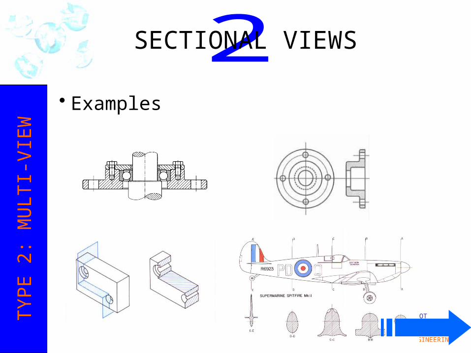
• Sectional Views– How an object looks if a cut were made through it
perpendicular to the direction of sight.– For example, if we cut the shape below at PRP 2 and
drew the shape (including its “insides”) we would have a sectional view:
SECTIONAL VIEWSTY
PE 2
: MU
LTI-V
IEW

IOT
POLY ENGINEERING2-10
• Sectional Views– Different materials have different sectional views
SECTIONAL VIEWSTY
PE 2
: MU
LTI-V
IEW
IOT
POLY ENGINEERING2-10
• Examples
SECTIONAL VIEWSTY
PE 2
: MU
LTI-V
IEW

IOT
POLY ENGINEERING2-10
• So far, our standard 6 views are all visible using the three regular planes of projection–Frontal Reference Plane–Horizontal Reference Plane–Profile Reference Plane
• Those views are drawn TRUE SIZE• However, inclines (slants) are not shown as true
size in standard views.
AUXILIARY VIEWSTY
PE 2
: MU
LTI-V
IEW

IOT
POLY ENGINEERING2-10
• Inclines (slants) are not shown as true size in standard views.
• Each square below represents 1”. What are the widths of the front view and right side views?– 9” and 4”, respectively
AUXILIARY VIEWSTY
PE 2
: MU
LTI-V
IEW
FRP
HRP
PRP
• Neither the front, top, or side view shows the true size and shape of the object’s inclined surface.

IOT
POLY ENGINEERING2-10
AUXILIARY VIEWSTY
PE 2
: MU
LTI-V
IEW
FRP
PRP
Which Reference Plane?HRP
ARPAuxiliary Reference Plane
The ARP shows true form (shape and size) for inclines

IOT
POLY ENGINEERING2-10
TYPE
2: M
ULT
I-VIE
WSURFACE DEVELOPMENTS

IOT
POLY ENGINEERING2-10
Stretchout Pattern Development• Used by many industries:
– Pipes and ducts– Aircraft and automobile parts– Storage tanks– Cabinets– Boxes and cartons– Packages
• Packaging is a very large industry that uses surface developments.
TYPE
2: M
ULT
I-VIE
WSURFACE DEVELOPMENTS

IOT
POLY ENGINEERING2-10
• Tells all that needs to be known for making a single part or a complete machine or structure– Precise size and shape– What materials are used– How finishing should be done (roughness/smoothness)– Degree of accuracy (% Error allowed)
TYPE
2: M
ULT
I-VIE
WWORKING DRAWINGS

IOT
POLY ENGINEERING2-10
• Pictorial drawings show a likeness (shape) of an object as viewed by the eye.
PICTORIAL DRAWINGSTY
PE 3
: PIC
TORI
AL

IOT
POLY ENGINEERING2-10
ISOMETRICTY
PE 3
: PIC
TORI
AL
Isometric Cube:
1) all lines equal length;
2) all faces equal area;
3) perimeter is a hexagon
• From Greek: Equal Measure– Isos: Equal– Metron: Measure
• The scale along each axis of the projection is the same• True form parallel lines are shown as parallel (note colors
below)• All isometrics: simple construction

IOT
POLY ENGINEERING2-10
• Latin: perspicere – to see through• An approximate representation of an image as it is
perceived by the eye. • The most characteristic feature of perspectives is that
objects are drawn:
Smaller as their distance from the observer increases
PERSPECTIVETY
PE 3
: PIC
TORI
AL

IOT
POLY ENGINEERING2-10
• A way of showing depth, like isometric• Part orthographic / part isometric:
– One face is true form– Parallel lines behind; either:
» Full scale» Half scale» Three-quarter scale
OBLIQUETY
PE 3
: PIC
TORI
AL
IOT
POLY ENGINEERING2-10
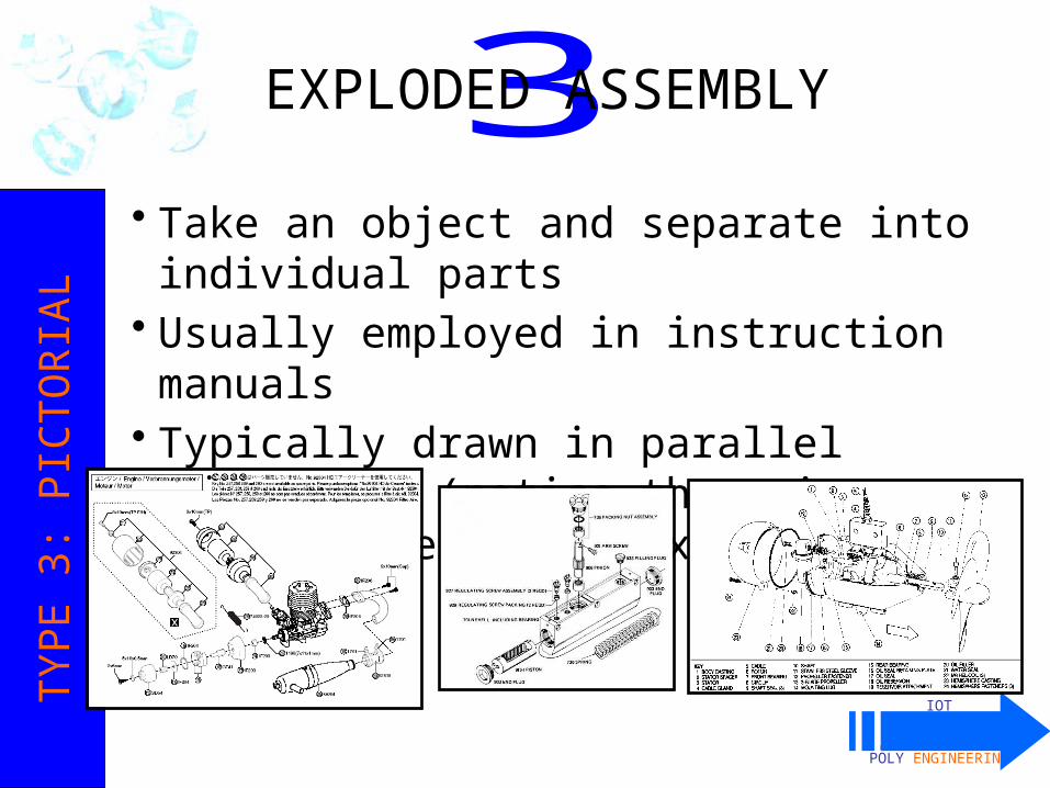
• Take an object and separate into individual parts• Usually employed in instruction manuals• Typically drawn in parallel projection (notice there
is no perspective in the examples below)
EXPLODED ASSEMBLYTY
PE 3
: PIC
TORI
AL

IOT
POLY ENGINEERING2-10
• Show the interior details of a product• Often employed in instruction manuals• Assists in understanding operation of product
CUT-AWAY PICTORIALTY
PE 3
: PIC
TORI
AL

No drawing tools
SKETCHES
IOT - Technical Graphic Communication
TECHNICAL DRAWING METHODS
Standard Views Sectional Views Auxiliary Views Developments Working Drawings
MULTI-VIEW DRAWINGS
Isometric Perspective Oblique Exploded Assembly Cutaway Pictorial
PICTORIAL DRAWINGS

IOT
POLY ENGINEERING2-10
Complete the orthographic projection worksheet, front and back
HOMEWORK
Com
mun
icati
on T
echn
olog
y