chapter 12 working with drawing views-i - … 12 working with drawing views-i ... orthographic view....
TRANSCRIPT
Chapter 12
Working With DrawingViews-I
After completing this chapter you will be able to:• Generate standard three views.• Generate Named Views.• Generate Relative Views.• Generate Predefined Views.• Generate Empty Views.• Generate Projected Views.• Generate Section Views.• Generate Aligned Section Views.• Generate Broken-out Section Views.• Generate Auxiliary Views.• Generate Detail Views.• Generate Crop Views.• Generate Broken Views.• Generate Alternate Position Views.• Generate the View of an Assembly in Exploded State.• Work with Interactive Drafting.• Edit the Drawing Views.• Change the Scale of the Drawing Views.• Delete Drawing Views• Modify the Hatch Pattern of the Section Views.• Apply Hatch Patterns to the Section Views.
Learning Objectives
c12-solidworks-2003.p65 5/12/2003, 8:23 AM1

12-2 SolidWorks for Designers
THE DRAWING MODEAfter you have created the solid models of the parts, or an assembly, you will have to generate thedrawing views. A 2D drawing is the life line of all the manufacturing systems because at the shopfloor or machine floor, the machinist mostly needs the 2D drawing for manufacturing. Therefore,SolidWorks has provided a specialized environment known as the Drawing mode. The Drawingmode has all the tools that are required to generate the drawing views, modify the drawing views,and add dimensions and annotations to the drawing views. In other words, you can get the finalshop floor drawing using this mode of SolidWorks. You can also create the 2D drawings in theDrawing mode of SolidWorks using the sketching tools provided in this mode. In other words,there are two types of drafting methods available in SolidWorks: Generative drafting and Interactivedrafting. Generative drafting is a technique of generating the drawing views using a solid modelor an assembly. Interactive drafting is a technique in which you use the sketching tools to sketcha drawing view in the Drawing mode. In this chapter, you will learn about generating the drawingviews of parts or assemblies. One of the major advantage of working in SolidWorks is that thissoftware is bidirectionally associative in nature. This property ensures that if the modificationsare made in a model in the Part mode, the same modification will be reflected in the Assemblymode and the Drawing mode, and vice versa.
For creating a new document in the Drawing mode, invoke the New SolidWorks Documentdialog box. Choose the Drawing template from the Templates tab as shown in Figure 12-1and choose the OK button.
Figure 12-1 The New SolidWorks Document dialog box
Tip. When you select the Drawing template from the Templates tab, the CreateRapidDraft Drawing check box is displayed at the lower right corner of thedialog box. You will learn more about rapid draft drawings later.
c12-solidworks-2003.p65 5/12/2003, 8:23 AM2

Working With Drawing Views-I 12-3
When you choose the OK button from the New SolidWorks Document dialog box, a newDrawing document is invoked. The Sheet Format To Use dialog box is also displayed.Figure 12-2 shows the initial screen of the drawing document with the Sheet Format to Usedialog box.
The Sheet Format To Use dialog box is used to specify the sheet and the format of sheet to beused. The options available in the this dialog box are discussed next.
Standard sheet formatThe Standard sheet format radio button is selected by default. Using this option you canselect the predefined standard sheet formats available in SolidWorks. You can select the sheetsize from the drop-down list available below the Standard sheet format radio button.
Custom sheet formatThe Custom sheet format radio button is used to add a user-defined sheet format to thedrawing sheet. Select the Custom sheet format radio button and choose the Browse buttonto invoke the Open dialog box. From the Open dialog box, you can select and open a
Figure 12-2 The initial screen of the drawing document with the Sheet Format To Use dialog box
c12-solidworks-2003.p65 5/12/2003, 8:23 AM3

12-4 SolidWorks for Designers
user-defined sheet format. You will learn more about creating a user-defined sheet format inlater chapters.
No sheet formatThe No sheet format radio button is selected if you want to use an empty sheet, without anymargin lines or title block. Select this radio button and select the size of sheet from thedrop-down list available below the No sheet format radio button and choose the OK button.
Figure 12-3 shows a drawing document created using A4 standard sheet format from thedrop-down list available below the Standard sheet format radio button.
Figure 12-3 Drawing document with A4 standard sheet format
Tip. If you choose the Cancel button from the Sheet Format To Use dialog box, ablank sheet of B size in landscape orientation will be inserted in the drawingdocument.
c12-solidworks-2003.p65 5/12/2003, 8:23 AM4
Working With Drawing Views-I 12-5
TYPE OF VIEWSIn SolidWorks, you can generate nine types of views. Generally, you first need to generate astandard view such as the top view or the front view and then use this view to derive theremaining views. After generating a standard view, you can generate or derive the followingviews from the standard view(s).
Projected ViewThe projected view is generated by taking an existing view as the parent view. This view isgenerated by projecting the lines normal to the parent view. The resultant view will be anorthographic view.
Section ViewA section view is generated by chopping a part of an existing view using a plane and thenviewing the parent view from a direction normal to the section plane.
Aligned Section ViewAn aligned section view is used to section those features that are created at a certain angle tothe main section planes. Align sections straighten these features by revolving them about anaxis that is normal to the view plane. Remember that the axis about which the feature isstraightened should lie on the cutting planes.
Auxiliary ViewAn auxiliary view is generated by projecting the lines normal to a specified edge of an existingview.
Detail ViewA detail view is used to display the details of a portion of an existing view. You can select theportion whose detailing has to be shown in the parent view. The portion that you have selectedwill be magnified and will be placed as a separate view. You can control the magnification ofthe detail view.
Broken ViewA broken view is used to display a component by removing a portion of it from between,keeping the ends of the drawing view intact. This type of view is used to display the componentswhose length to width ratio is very high. This means that either the length is very large ascompared to the width or the width is very large as compared to the length. The broken viewwill break the view along the horizontal or vertical direction such that thedrawing view fits the area you require.
Broken-out SectionA broken-out section view is used to remove a part of the existing view and display the area ofthe model or the assembly that lies behind the removed portion. This type of view is generatedusing a closed sketch that is associated with the parent view.
c12-solidworks-2003.p65 5/12/2003, 8:23 AM5

12-6 SolidWorks for Designers
Crop ViewA crop view is used to crop an existing view enclosed in a closed sketch associated to that view.The portion of the view that lies inside the associated sketch is retained and the remainingportion is removed.
Alternate Position ViewThe alternate position view is used to create a view in which you can show the maximum andminimum range of motion of the assembly. The main position is displayed in the drawingview in continuous lines and the alternate position of the assembly is shown in the same viewin dashed lines (phantom lines).
GENERATING THE DRAWING VIEWSThe methods of generating various types of drawing views are discussed next.
Generating the Standard Drawing ViewsThe various options of generating the standard views are discussed next.
Generating the Three Standard Views
Using the Standard 3 View option, you can generate three default orthographic viewsof the part or the assembly. For creating the three standard views, choose the Standard3 View button from the Drawing toolbar or choose Insert > Drawing View > Standard
3 View from the menu bar. The Standard View PropertyManager will be displayed as shownin Figure 12-4 and the select cursor is replaced by the part selection cursor. The Messagerollout available in the Standard View PropertyManager lists the various options that youcan use to select the model whose views are to be generated. The various options of selectingthe model whose views are to be generated are discussed next.
From FileAfter invoking the Standard View PropertyManager, right-click in the drawing area toinvoke the shortcut menu. Choose the Insert From File option from the shortcut menu.The Open dialog box will be displayed. Browse and select the part or assembly documentto generate the drawing views and choose the Open button from the Open dialog box.The Tangent Edge Display dialog box is displayed. Choose OK from this. You will learnmore about this dialog box later. The three standard orthographic views of the selectedmodels are generated.
Selecting the model from the graphics area of another windowTo select the model for generating the three drawing views using this option, you firstneed to open the part document from which you need to generate the views. ChooseWindow > Tile Horizontally/Tile Vertically to tile the part and the drawing documents.If the drawing document is not active, select the title bar of the drawing window onceto activate it. Now, choose the Standard 3 View button from the Drawing toolbar, and
Toolbar: Drawing > Standard 3 ViewMenu: Insert > Drawing View > Standard 3 View
c12-solidworks-2003.p65 5/12/2003, 8:23 AM6

Working With Drawing Views-I 12-7
Figure 12-4 The Standard View PropertyManager
move the cursor in the drawing area of the part document and pick a point. Choose OKfrom the Tangent Edge Display dialog box that is displayed. The three standard views ofthe selected model are generated in the drawing document. You can also generate thethree standard views of an assembly using the same procedure.
Selecting the model from the FeatureManager Design Tree of another windowOpen the part document whose drawing views are to be generated and tile the windowhorizontally or vertically. Now, choose the Standard 3 View button from the Drawingtoolbar, and move the cursor to the FeatureManager Design Tree of the part window.Select the name of the part displayed on the top of the FeatureManager Design Tree andchoose OK from the Tangent Edge Display dialog box. The three standard orthographicviews are generated in the drawing document.
Selecting a view containing the modelThis option is used only if another view is generated on the drawing view. If one view isavailable in the drawing view, choose the Standard 3 View button from the Drawingtoolbar and select the view from the drawing area. The three standard orthographic viewswill be generated in the drawing document.
Figure 12-5 shows the three standard views of a model created using the Standard 3 Viewtool.
c12-solidworks-2003.p65 5/12/2003, 8:23 AM7

12-8 SolidWorks for Designers
Figure 12-5 Three standard views created using the Standard 3 View tool
Tip. If the generated view overlaps the title block, you need to move it. To move aview, move the cursor over it. The bounding box of the view is displayed in graycolor. At this point, left-click to select the view. Now, move the cursor to the boundaryof the selected view; the cursor is replaced by the move cursor. Press and hold downthe left mouse button and drag the cursor to move the view. Remember that if youmove the front view, all the views are moved.
If the bounding box of the view appears in red dashed lines, you need to set thedynamic view activation option from the System Options dialog box. Choose Tools> Options from the menu bar to display the System Options - General dialogbox. Select the Drawing option to display the settings related to the Drawingmode. Select the Dynamic drawing view activation check box.
NoteYou will observe that the name of the part document whose drawing views are generated isdisplayed in the DWG NO. text box of the title block. The size of the sheet is also displayed at thelower right corner of the title block. You will also learn to generate all the information like drawby, check by, and so on as you generate the drawing views later.
c12-solidworks-2003.p65 5/12/2003, 8:23 AM8

Working With Drawing Views-I 12-9
Generating the Standard View Using the Named View Tool
The Named View tool is used to create a standard view, such as front, right, top,bottom, isometric, and so on. The type of view is defined while placing the view in thedrawing document. To create a named view, open the part or assembly document and
drawing document and tile the windows horizontally or vertically. Choose the Named Viewbutton from the Drawing toolbar or choose Insert > Drawing View > Named View from themenu bar. The Named View PropertyManager is invoked, which lists the various methods of
Figure 12-6 Standard views generated in third angle projection
Toolbar: Drawing > Named ViewMenu: Insert > Drawing View > Named View
Tip. By default, the views in the drawing document of SolidWorks are generatedusing the First Angle projection. If you need to create the views in the ThirdAngle projection, then before generating the views select Sheet 1 from theFeatureManager Design Tree and invoke the shortcut menu. Choose theProperties option; the Sheet Setup dialog box is displayed. Select the Thirdangle radio button from the Type of projection area and choose OK. You willlearn more about the other options available in the Sheet Setup dialog box later.Figure 12-6 shows the standard orthographic views in the Third Angle projection.
c12-solidworks-2003.p65 5/12/2003, 8:23 AM9

12-10 SolidWorks for Designers
Figure 12-7 The Named PropertyManager
selecting the part, and the select cursor is replaced by the part selection cursor. Select the partor the assembly from the document window. Select the Maximize button from the drawingdocument to maximize the drawing document. The cursor is replaced by the place viewcursor. The View Orientation and the Custom Scale rollouts are displayed in the NamedView PropertyManager as shown in Figure 12-7.
By default, the Isometric option is selected in the View Orientation area. Therefore, if youplace the view in the drawing document, the isometric view will be generated. If you need thefront view of the model, select the Front option from View Orientation area and place theview in the drawing view. The other options available in this PropertyManager will be discussedlater.
Tip. If you suppress the features of a model whose drawing views are generated, thesuppressed features will not be displayed in the drawing views. As you unsuppressthe feature, it will be displayed in the drawing views.
When you hide or suppress the components of an assembly, the hidden or suppressedcomponents are not displayed in the drawing views.
c12-solidworks-2003.p65 5/12/2003, 8:23 AM10

Working With Drawing Views-I 12-11
NoteIf you select the Preview button available in the View Orientation rollout, the preview of theview to be placed will be displayed in the drawing area.
If you choose the Current Model View option from the View Orientation area, the view of thecurrent orientation of the model in the part document will be placed in the drawing document.When you place the view using the Current Model View option, the SolidWorks dialog boxwill be displayed. This dialog box prompts you that this view may need Isometric (True) dimensionsinstead of standard Projected dimensions. Do you want to switch the view to use Isometricdimensions? It is always recommended to use isometric dimensions in a 3D view. You will learnmore about dimensions in the later chapters.
Generating the Standard View Using the Relative View Tool
The Relative View tool is used to generate an orthographic view. The orientation ofthe view is defined by selecting the reference planes or the planar faces of the model.This option is very useful if you need the orientation of the parent view other than
the default orientations. To create a relative view open the documents and tile themvertically or horizontally. Choose the Relative button from the Drawing toolbar or chooseInsert > Drawing View > Relative To Model from the menu bar. If the Relative buttonis not available in the Drawing toolbar, you need to customize the toolbar. The RelativeView PropertyManager is displayed, which prompts you to select the model.
Select the model or the assembly using the face that you want to use to orient the resultantview. The Drawing View Orientation dialog box is displayed as shown in Figure 12-8.
Now from the drop-down list in this dialog box select the option toward which the selectedface will be oriented. Choose the OK button. Next, select another face and then select theoption toward which the second selected face will be oriented. Move the cursor in thedrawing document; the cursor will be replaced by the place view cursor. The preview ofthe view of is also displayed in the drawing document. Place the view at an appropriateplace in the drawing document.
Figure 12-9 shows the faces of the model selected to generate a standard view andFigure 12-10 shows the resultant view.
Toolbar: Drawing > Relative View (Customize to Add)Menu: Insert > Drawing View > Relative To Model
Figure 12-8 The Drawing View Orientation dialog box
c12-solidworks-2003.p65 5/12/2003, 8:23 AM11

12-12 SolidWorks for Designers
Figure 12-9 Faces to be selected
Figure 12-10 Resultant view
Generating the Standard View Using the Predefined View Tool
The Predefined View tool is used to create empty views with the specified orientation.After creating all the predefined views, populate them by dragging the part from theother window. All the predefined views will be populated. This option is basically
used to add the empty views in the drawing document and then save it as a drawing template.Next time when you open a new drawing document using that template, you just need to dragand drop the part from other window; all the predefined views will be populated. You will
Toolbar: Drawing > Predefined ViewMenu: Insert > Drawing View > Predefined
c12-solidworks-2003.p65 5/12/2003, 8:23 AM12

Working With Drawing Views-I 12-13
Figure 12-11 The Predefined View PropertyManager
learn more about creating a drawing template in the later chapters. To create the predefinedviews, choose the Predefined View button from the Drawing toolbar or choose Insert >Drawing > Predefined from the menu bar. An empty view is attached to the cursor. Specify apoint in the drawing document to place the predefined view. The view will be placed in thedrawing document and the Predefined View PropertyManager is displayed as shown inFigure 12-11.
Select the view orientation from the View Orientation area of the View Orientation rolloutand choose the OK button from the Predefined View PropertyManager. To add the nextpredefined view, you need to define the alignment option while placing the view. To createadditional predefined view, invoke the Predefined View tool and place the view in the drawingsheet. The bounding box of the view is displayed. Right-click inside the bounding box andchoose Alignment > Align Horizontal by Center/Align Vertical by Center. Now select theprevious predefined view to align the corresponding view. Similarly, add other predefinedviews using this tool.
After creating all the predefined views open a part or an assembly document and tile thedocuments windows horizontally or vertically. Now, drag the component from the partdocument and drop in the drawing document; all the predefined views will be populated.
c12-solidworks-2003.p65 5/12/2003, 8:23 AM13

12-14 SolidWorks for Designers
Figure 12-13 Views created after populating the predefined views
Figure 12-12 Different predefined views
Tip. You can add the views of different parts and assemblies in each predefinedview. In this way, you can have the dimensions of different parts and assemblies ina single drawing document. For adding different parts in each predefined view,select the predefined view and choose the Browse button from the Insert Modelrollout of the Predefined View PropertyManager. The Open dialog box isdisplayed and you can select the part or the assembly to be inserted in the selectedpredefined view.
Figure 12-12 shows the selected predefined views with the orientation in which the views arecreated. Figure 12-13 shows the drawing document after drooping the part in the drawingdocument. Note that in these figures, the views are not aligned to each other.
c12-solidworks-2003.p65 5/12/2003, 8:23 AM14

Working With Drawing Views-I 12-15
NoteWhen you generate the views in the Drawing mode of SolidWorks, the views are scaledautomatically depending upon the size of the sheet.
In case of predefined view, if the drawing contains more than one predefined view, the views willbe scaled automatically.
If only one predefined view is placed in the drawing document, the view will be scaled withrespect to the Custom Scale value if specified. Otherwise, the view will be scaled with thedefault scale factor of the drawing sheet. You can change the view scale using the Sheet Setupdialog box. You will learn more about scaling the views in later chapters.
Empty View
The Empty View tool is used to create an empty view. The empty views are used tocreate the sketches in the drawing document. This option is used in interactive drafting.Interactive drafting is discussed later in this chapter. To create an empty view, choose
the Empty View button from the Drawing toolbar or choose Insert > Drawing View >Empty option from the menubar. If the Empty View button is not available in the Drawingtoolbar, then you need to customize the toolbar. An empty view is attached to the cursor.Select a point at the desired location in the drawing document to place an empty view.
Generating the Derived ViewsAll the views that are generated from a view already placed in the drawing document areknown as derived views. The various types of derived views that are generated from the standardviews are
1. Projected view2. Section view3. Aligned Section view4. Broken-out Section view5. Auxiliary view6. Detail view7. Crop view8. Broken view9. Alternate Position view
The methods of generating the various derived drawing views are discussed next.
Toolbar: Drawing > Empty View (Customize to Add)Menu: Insert > Drawing View > Empty
c12-solidworks-2003.p65 5/12/2003, 8:23 AM15

12-16 SolidWorks for Designers
Generating Projected Views
As mentioned earlier, the projected views are generated by projecting the normallines from an existing view. To generate a projected view, choose the Projected Viewbutton from the Drawing toolbar or choose Insert > Drawing View > Projected
from the menu bar. The Projected View PropertyManager is displayed and it prompts you toselect a drawing view from which you need to project the normal lines. The select cursor isreplaced by the view cursor. Select the parent view and move the cursor vertically to generatea top view or a bottom view or move the cursor toward the left or right to create a right viewor left view. Specify a point on the drawing sheet to place the view. For creating more than oneprojected view, choose the Keep Visible button to pin the Projected View PropertyManager.Figure 12-14 shows the front view generated from the top view.
Toolbar: Drawing > Projected ViewMenu: Insert > Drawing View > Projected
Figure 12-14 Front view generated from the top view
Tip. When you generate a projected drawing view, the drawing view is aligned tothe parent view. To place the projected view that is not in alignment with the parentview, press and hold down the CTRL key before placing the view. Now move thecursor to the desired location and place the view.
All the standard views and derived views that include projected views, sectionview, detailed view, and so on are linked to their parent view by a Parent-Childrelationship. If you select the child view, the boundaries of the parent view will bedisplayed in yellow.
Select the child view and invoke the shortcut menu and choose the Jump to ParentView option from the shortcut menu. The parent view will be selected automatically.
c12-solidworks-2003.p65 5/12/2003, 8:23 AM16

Working With Drawing Views-I 12-17
Toolbar: Drawing > Section ViewMenu: Insert > Drawing View > Section
Generating Section Views
As mentioned earlier, section views are generated by chopping a portion of an existingview using a cutting plane and then viewing the parent view from the direction normalto the cutting plane. To create a section view, you first need to activate the view in
which you need to create the section line or cutting plane. To invoke the drawing view, movethe cursor to the drawing view. The view symbol will be displayed below the cursor and thebounding box of the view is displayed. Left-click to activate the drawing view. Now, choose theSection View button from the Drawing toolbar or choose Insert > Drawing > Section fromthe menu bar. The Section View PropertyManager is displayed and it prompts you to sketcha line to continue view creation. You can zoom using the Zoom tool to increase the displayarea of the activated view. Draw a line that will define the section plane. As soon as you specifythe endpoint of the section line the Section View PropertyManager is displayed. The sectionview is also displayed in the drawing area and the name of the section view is displayed on thesection line. Move the cursor and specify a point on the drawing sheet to place the sectionview. The name and the scale factor of the drawing view is displayed below the section view.The Section View PropertyManager is still available in the drawing document as shown inFigure 12-15.
You can use the Flip direction check box to flip the direction of the section view. The view willbe automatically modified in the drawing sheet. The Scale with model check box is used to
Figure 12-15 The Section View PropertyManager
c12-solidworks-2003.p65 5/12/2003, 8:23 AM17

12-18 SolidWorks for Designers
Figure 12-16 The section view
scale the drawing view if the model is scaled in the part document. You will learn more aboutscaling the model in the later chapters. Choose OK from the Section View PropertyManager.Figure 12-16 shows the top view and the section view of a model.
To create a half section view, make the section lines extended beyond the parent view, seeFigure 12-17.
Figure 12-17 The half section view
c12-solidworks-2003.p65 5/12/2003, 8:23 AM18

Working With Drawing Views-I 12-19
NoteYou will observe that by default the spacing of the hatch is not what is required. Therefore, youmay need to increase the spacing of the hatch pattern. You will learn more about editing thehatch pattern later in this chapters.
There are some other options available in the Section View PropertyManager using whichyou can create partial section view and the surface section view. The options are discussed next
Creating the Partial Section ViewIf the section line does not cut through the model, the SolidWorks information box willbe displayed. This dialog box prompts you that the section line does not completely cutthrough the bounding box of the model in this view. Do you want this to be a partialsection cut? For creating the partial section view, choose the Yes button from this dialogbox. If you choose the No button from this dialog box, then the complete section viewwill be created. Figure 12-18 shows a partial section view generated from the top view.
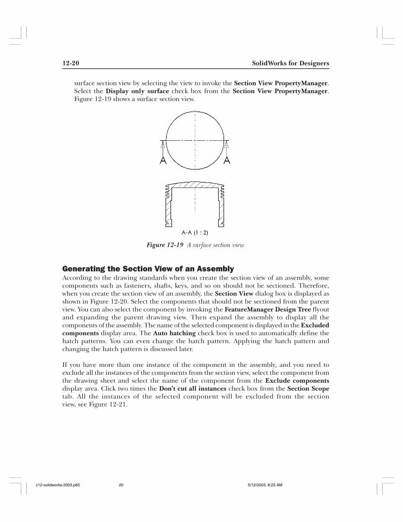
Creating the Surface Section ViewA surface section view is the one in which only the sectioned surface is displayed in thesection view. All the other edges or faces are not displayed in the surface section view. Forcreating a surface section view first you need to create the section view and then choosethe Display only surface check box from the Section View PropertyManager. Choosethe OK button from the PropertyManager. You can also replace the section view by a
Tip. When you create a section view and move the cursor to place the section view,you will observe that the view is aligned to direction of arrows on the section line.If you need to remove this alignment to place the section view, press and hold downthe CTRL key and move the view to the desired location. Select a point in thedrawing sheet to place the view.
Figure 12-18 A partial section view
c12-solidworks-2003.p65 5/12/2003, 8:23 AM19
12-20 SolidWorks for Designers
Figure 12-19 A surface section view
surface section view by selecting the view to invoke the Section View PropertyManager.Select the Display only surface check box from the Section View PropertyManager.Figure 12-19 shows a surface section view.
Generating the Section View of an AssemblyAccording to the drawing standards when you create the section view of an assembly, somecomponents such as fasteners, shafts, keys, and so on should not be sectioned. Therefore,when you create the section view of an assembly, the Section View dialog box is displayed asshown in Figure 12-20. Select the components that should not be sectioned from the parentview. You can also select the component by invoking the FeatureManager Design Tree flyoutand expanding the parent drawing view. Then expand the assembly to display all thecomponents of the assembly. The name of the selected component is displayed in the Excludedcomponents display area. The Auto hatching check box is used to automatically define thehatch patterns. You can even change the hatch pattern. Applying the hatch pattern andchanging the hatch pattern is discussed later.
If you have more than one instance of the component in the assembly, and you need toexclude all the instances of the components from the section view, select the component fromthe drawing sheet and select the name of the component from the Exclude componentsdisplay area. Click two times the Don’t cut all instances check box from the Section Scopetab. All the instances of the selected component will be excluded from the sectionview, see Figure 12-21.
c12-solidworks-2003.p65 5/12/2003, 8:23 AM20

Working With Drawing Views-I 12-21
Figure 12-20 The Section View dialog box
Figure 12-21 Section view of an assembly with some of thecomponents excluded from the section scope
Tip. You can add or remove the components that are sectioned by right-clicking thedrawing view and choosing Properties from the shortcut menu. Now, choose theSection Scope tab and add or remove the components.
c12-solidworks-2003.p65 5/12/2003, 8:23 AM21

12-22 SolidWorks for Designers
Figure 12-22 Aligned section view
Toolbar: Drawing > Aligned View (Customize to Add)Menu: Insert > Drawing View > Aligned Section
Generating Aligned Section Views
This tool is used to generate a section view of the component in which at least one ofthe feature is at an angle. In the aligned section view, the section portion revolvesabout an axis normal to the viewing plane such that it is straightened. For example,
refer to Figure 12-22. This figure explains the concept of an aligned section view of a model.Notice that the inclined feature that is sectioned in this view is straightened. As a result, thesection view is longer than the parent view. To create the aligned section view, activate theview. Choose the Aligned Section button from the Drawing toolbar or choose Insert > DrawingView > Aligned Section from the menu bar. Draw the sketch that defines the section line.The aligned section view will be attached to the cursor; place the view at an appropriatelocation in the drawing sheet. Note that the resultant view will be projected normal to the linethat is drawn in the end in the section sketch. Therefore, to get the aligned section viewsimilar to that shown in Figure 12-22, the inclined line in the section sketch should be drawnfirst than the vertical line. Figure 12-23a shows the aligned section view in which the verticalline in the section sketch is drawn first. This is the reason the section view is projected normalto the inclined line that is drawn last. On the other hand, Figure 12-23b shows the views inwhich the inclined line is drawn first.
c12-solidworks-2003.p65 5/12/2003, 8:23 AM22

Working With Drawing Views-I 12-23
NoteYou can also create a sketch associated to a view. This sketch can be selected as the section planefor generating the section view. To create an associated sketch, active the view and draw thesketch that defines the section plane using the Line tool.
If you create a sketch to define the section plane for the aligned section view before invoking theAligned Section View tool, the view will be projected normal to the line that you select last.However, if you select the sketch to define section plane by dragging a window around it, theview will be projected normal to the line that was drawn last.
Generating Broken-out Section Views
This tool is used to create a broken-out section view. A broken-out section view is usedto remove a part of the existing view and display the area of the model or the assemblybehind the removed portion. This type of view is generated using a closed sketch that
is associated with the parent view. To create a broken-out section view, activate the view onwhich you need to create the broken out section view. Choose the Broken-out Section buttonfrom the Drawing toolbar or choose Insert > Drawing View > Broken-out Section from themenu bar. The Broken-out Section PropertyManager is displayed and it prompts you tocreate the closed spline to continue section creation. The cursor will be replaced by thespline cursor. Create a closed sketch using the spline cursor. If you do not want a splineprofile, select a closed profile before choosing the Broken-out Section button. Figure 12-24shows an associated sketch created for creating a broken-out section view.
When you create a closed sketch, some options are displayed in the Broken-out SectionPropertyManager as shown in Figure 12-25 and it prompts you to specify the depth of thebroken-out section. Choose the Preview check box to preview the broken-out section view.
Figure 12-23a Aligned section view Figure 12-23b Aligned section view
Toolbar: Drawing > Broken-out SectionMenu: Insert > Drawing View > Broken-out Section
c12-solidworks-2003.p65 5/12/2003, 8:23 AM23

12-24 SolidWorks for Designers
The Auto hatching check box is used to define the hatch pattern automatically to thesection drawing view of the assembly. If you are creating the broken-out section view of a part,then the Auto hatching check is not available in the Broken-out Section PropertyManager.Figure 12-26 shows the preview of the broken-out section view.
Figure 12-24 Sketch for creating the broken-out section view
Figure 12-25 The Broken-out Section PropertyManager
c12-solidworks-2003.p65 5/12/2003, 8:23 AM24
Working With Drawing Views-I 12-25
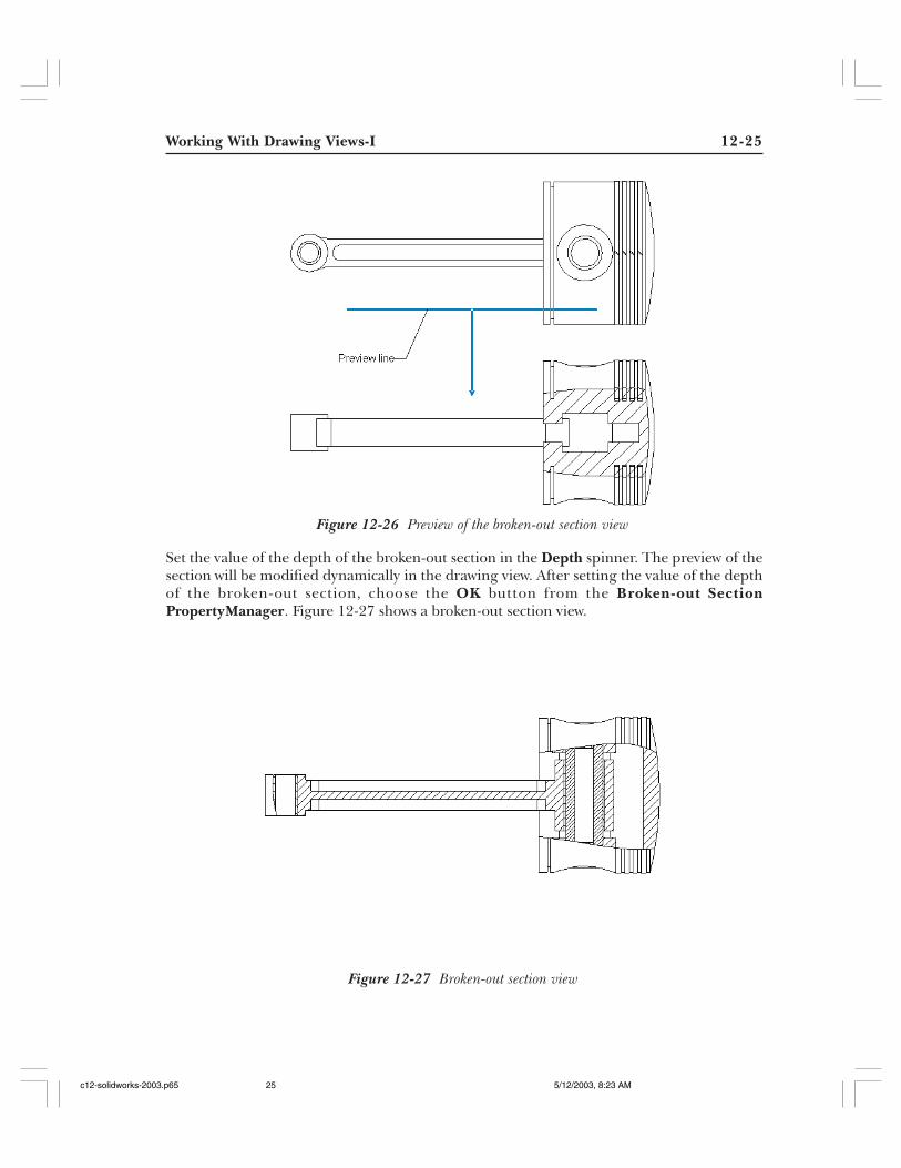
Set the value of the depth of the broken-out section in the Depth spinner. The preview of thesection will be modified dynamically in the drawing view. After setting the value of the depthof the broken-out section, choose the OK button from the Broken-out SectionPropertyManager. Figure 12-27 shows a broken-out section view.
Figure 12-27 Broken-out section view
Figure 12-26 Preview of the broken-out section view
c12-solidworks-2003.p65 5/12/2003, 8:23 AM25

12-26 SolidWorks for Designers
Figure 12-28 The Auxiliary View PropertyManager
Generating Auxiliary Views
This tool is used to generate an auxiliary view. An auxiliary view is a drawing view thatis generated by projecting the lines normal to a specified edge of an existing view. Tocreate an auxiliary view, choose the Auxiliary View button from the Drawing toolbar
or choose Insert > Drawing View > Auxiliary from the menu bar. The Auxiliary ViewPropertyManager is displayed and it prompts you to select a reference edge to continue.Select the edge that will be the reference to generate the auxiliary view. A view will be attachedto the cursor and some options are displayed in the Auxiliary View PropertyManager asshown in Figure 12-28. Now, the Auxiliary PropertyManager prompts you to select a locationof new view. Select a point on the drawing sheet to place the auxiliary view.
The Display View Arrow check box available in the Display View Arrow rollout is used todisplay the arrow of the viewing plane in the drawing views. The name of the auxiliary view isspecified in the Label edit box. Using the Flip Direction check box you can flip the viewingdirection for creating the auxiliary view. Figure 12-29 shows the reference edge to be selectedto create the auxiliary view. Figure 12-30 shows the auxiliary view created with the defaultviewing direction. Figure 12-31 shows the auxiliary view created with the Flip Direction checkbox selected.
NoteYou can also create a sketch using the sketch tools available in the Sketch Tools toolbar to selectas a reference edge for generating the auxiliary view.
Toolbar: Drawing > Auxiliary ViewMenu: Insert > Drawing View > Auxiliary
c12-solidworks-2003.p65 5/12/2003, 8:23 AM26

Working With Drawing Views-I 12-27
Figure 12-29 Reference edge to be selected to create the auxiliary view
Figure 12-30 Auxiliary view created with theFlip Direction check box cleared
Figure 12-31 Auxiliary view created with theFlip Direction check box selected
Generating Detail Views
This tool is used to generate the detail view. A detail view is used to display the detailsof a portion of an existing view. You can select the portion whose detailing has to beshown in the parent view. The portion that you select will be magnified and placed as
a separate view. You can control the magnification of the detail view. To create a detail view,you first need to activate the view from which you will generate the detail view. Choose theDetail View button from the Drawing toolbar or choose Insert > Drawing View > Detail
Toolbar: Drawing > Detail ViewMenu: Insert > Drawing View > Detail
c12-solidworks-2003.p65 5/12/2003, 8:23 AM27

12-28 SolidWorks for Designers
Figure 12-32 The Detail View PropertyManager
from the menu bar. The Detail View PropertyManager is displayed and it prompts you tosketch a circle to continue view creation. The cursor is replaced by a circle cursor. Create thecircle on the portion of the view that is to be displayed in the detail view.
As soon as you draw the circle, the detail view is attached to the cursor and some options aredisplayed in the Detail View PropertyManager as shown in Figure 12-32. You are also promptedto select a location for the new view. Specify a point on the drawing sheet to place the view.The options available in the Detail View PropertyManager are discussed next.
Tip. You can also create closed profile other than circle for creating the detail view.For this you need to create the closed profile in the current active view before invokingthe Detail View cursor. After creating the closed profile, select the profile andinvoke the Detail View tool.
c12-solidworks-2003.p65 5/12/2003, 8:23 AM28

Working With Drawing Views-I 12-29
Circle OptionsThe Circle Options rollout is used to define the options to display the circle of the detailview. Using the options available in the rollout, you can also apply the leader to the detailview. The options available in this rollout are discussed next.
StyleThe Style area has the Style drop-down list to specify the style of the closed profile.By default, the Circle radio button is selected below the Style drop-down list.Therefore, the portion of the parent view that is shown in the detail view is highlightedin circle. If you have created a closed profile for defining the portion to be shown inthe detail view, select the Profile radio button. The options available in the Styledrop-down list are discussed next.
Per Standard. The Per Standard option is used to create the detail view as perdefault standards.
Broken Circle. The Broken Circle option is used to display the area of the parentview to be displayed in the detailed view in a broken circle.
With Leader. The With Leader option is used to add the leader to the callout ofthe detail view.
No Leader. The No Leader option is used to remove the leader from the calloutof the detail view.
Connected. This option is used to create a line that connects the detail view withthe closed profile in the parent view.
View OptionsThe View Options rollout is used to set the parameters of the detail view. The variousoptions available in this rollout are discussed next.
Full outlineThe Full outline check box is used to display the complete outline of the closedprofile in the detail view.
Pin positionThe Pin position check box is used to pin the position of the detail view.
Scale hatch patternThe Scale hatch pattern check box is used to scale the hatch pattern with respect tothe scale factor of the detail view when you create a detail view of a section view.
Figure 12-33 shows the detail view created using the Detail View tool.
c12-solidworks-2003.p65 5/12/2003, 8:23 AM29

12-30 SolidWorks for Designers
Figure 12-33 Detail views
Toolbar: Drawing > Crop View (Customize to Add)
Tip. When you create a detail view, by default the detail view is scaled as 1:1. Youcan define the scale factor in the System Options dialog box so that whenever youcreate a detail view, it will be created with the scaling factor provided by you. Tospecify the scale factor for the detail view, invoke the System Options dialog boxand select the Drawings option from the left of this dialog box. Set the value of thescale factor of the detail view in the Detail View Scaling edit box and choose theOK button. Hence forth, the detail view will be created of the scale factor defined inthe System Options dialog box.
If you need to scale a detail view in the current drawing sheet, select the view andselect the Custom Scale check box. Specify the scale factor in the Custom Scalerollout and choose the OK button from the Detail View PropertyManager. Thescaling of other views is discussed later in this chapter.
Cropping Drawing Views
This tool is used to crop an existing view using a closed sketch associated to that view.The portion of the view that lies inside the associated sketch is retained and theremaining portion is removed. To crop the view, you first need to create a closed
profile associated to the view that defines the area of the view that will be displayed. The areaof the view outside this closed profile will not be displayed when you crop the view. Select theclosed profile and choose the Crop View (Customize to Add) button from the Drawing toolbar.Figure 12-34 shows the closed profile used to crop the view. Figure 12-35 shows a crop view.
c12-solidworks-2003.p65 5/12/2003, 8:23 AM30

Working With Drawing Views-I 12-31
Broken ViewA broken view is used to display a component by removing a portion of it from between,keeping the ends of the drawing view intact. This type of view is used for displaying thecomponents whose length to width ratio is very high. This means that either the length is verylarge as compared to the width or the width is very large as compared to the length. Thebroken view will break the view along the horizontal or vertical direction such that the drawingview fits the area you require. To create a broken view, you first need to define the break line.Select the view you need to break and choose Insert > Horizontal Break/Vertical Breakdepending on the direction in which you need to break the component. Two break lines willbe displayed on the selected view as shown in Figure 12-36.
After adding the break lines, you need to move the break lines to define the gap in the brokenview. Select the break lines and move them away from each other as shown in Figure 12-37.Now, select the view and invoke the shortcut menu. Choose the Break View option from theshortcut menu. The broken view will be created as shown in Figure 12-38.
Tip. You can remove the cropping of view by selecting the crop view and invokingthe shortcut menu. Choose Crop View > Remove Crop from the shortcut menu.The initial view will be displayed in the drawing sheet.
If you need to edit the closed profile of the crop view, select the crop view and invokethe shortcut menu. Choose Crop View > Edit Crop from the shortcut menu. Thesketch of the closed profile and the complete view is displayed in the drawing sheet.Edit the closed profile and choose the Rebuild button from the Standard toolbaror use CTRL+B from the keyboard.
Figure 12-34 Closed profile to crop the view Figure 12-35 Resultant crop view
c12-solidworks-2003.p65 5/12/2003, 8:23 AM31

12-32 SolidWorks for Designers
Figure 12-37 Extended gap between break lines Figure 12-38 Resultant broken view
NoteSelect the break line to increase or decrease the gap between the broken view. As you move thebreak line, the broken view is modified dynamically.
If you generate a projected view from a broken view, the resultant projected view is also a brokenview.
You can also break an isometric view; the procedure of breaking an isometric view or any 3Dview is the same as discussed earlier. Figure 12-39 shows a broken isometric view.
If you break a 3D view placed horizontally, the two parts of the view as a result of the BrokenView tool will lose their alignment.
Figure 12-36 Break lines added to the view
c12-solidworks-2003.p65 5/12/2003, 8:23 AM32

Working With Drawing Views-I 12-33
Alternate Position View
The alternate position view is used to create a view in which you can show the maximumand minimum range of motion of an assembly. The main position is displayed withcontinuous lines in the drawing view and the alternate position of the assembly is
shown in the same view with dashed (phantom) lines. To create an alternate position view,first you need to activate and select the view of the assembly drawing on which you need tocreate the alternate position view. Choose the Alternate Position View (Customize to Add)button from the Drawing toolbar or choose Insert > Drawing View > Alternate Positionfrom the menu bar. The Alternate Position PropertyManager is displayed as shown inFigure 12-40.
Tip. You can change the style of the break line by selecting the break line andinvoking the shortcut menu. The various break line styles available are straightcut, curve cut, zig zag cut, and small zig zag cut.
To unbreak the broken view, select the view and invoke the shortcut menu. Choosethe Un-Break View option from the shortcut menu.
Select the view and invoke the shortcut menu. Choose the Break View option toagain break the view.
If you select the break lines and press the DELETE key from the keyboard, thebroken view will be replaced by the parent view.
Figure 12-39 A broken isometric view
Toolbar: Drawing > Alternate Position View (Customize to Add)
Menu: Insert > Drawing View > Alternate Position
c12-solidworks-2003.p65 5/12/2003, 8:23 AM33

12-34 SolidWorks for Designers
Figure 12-40 The Alternate Position PropertyManager
The Alternate Position PropertyManager prompts you to select New configuration, click OKor Enter and define the new configuration parameters. Or Select Existing configuration andclick OK or Enter. But you have not created any configurations yet. Therefore, the NewConfiguration radio button is automatically selected to create a new configuration. Enter thename of the configuration in the edit box given below. Choose the OK button from theAlternate Position PropertyManager to create a new configuration. Choose OK from theTangent Edge Display dialog box
The assembly document is invoked and the Move Component PropertyManager is displayedin the assembly document. The Move Component PropertyManager prompts you to movethe desired components to the position to be shown in the alternate view. Note that thecomponent or components that you need to move to show in the alternate view should havethat particular degree of freedom free to move. These components should not be fully definedin the assembly. Select and drag the cursor to move the components to the desired location.After defining the alternate position of the components, choose the OK button from theMove Component PropertyManager. You will return to the drawing document automatically.The alternate position of the components that are moved will be displayed in phantom linesin the drawing view, see Figure 12-41.
You can also create the alternate position view of an isometric view or of any 3D view. Theprocedure of creating the alternate position view of a 3D view is the same as that discussedearlier. Figure 12-42 shows the alternate position view of an isometric view.
c12-solidworks-2003.p65 5/12/2003, 8:23 AM34

Working With Drawing Views-I 12-35
NoteWhen you create an alternate view of an assembly, a new configuration is created inside theassembly document with the same name that is specified to the configuration while creating thealternate position view. Open the assembly document and invoke the ConfigurationManager;you will observe that a new configuration is created along with the default configuration. Bydefault, the newly created configuration is selected. Therefore, the assembly is displayed with thecomponent moved to their extreme positions. To switch back to the default configuration, selectDefault from the ConfigurationManager and invoke the shortcut menu. Choose the ShowConfiguration option from the shortcut menu. You will observe that the assembly will be displayedwith the moved components back at their original positions. If the Show Configuration optionis not available in the shortcut menu, the assembly is at the default configuration.
Figure 12-41 Alternate position view
Figure 12-42 Alternate view of an isometric view.
c12-solidworks-2003.p65 5/12/2003, 8:23 AM35

12-36 SolidWorks for Designers
Figure 12-43 Drawing view of the exploded state with explode lines
Tip. If currently the assembly in the assembly document is in the exploded state,then if you drag and drop the assembly to generate the drawing views, all the viewsof the assembly will be generated in the exploded state.
If you need to switch to the collapse state in the drawing view, select the model andclear the Show in exploded state check box from the Drawing View Propertiesdialog box.
Creating the Drawing view of the Exploded State of the AssemblyYou can create the drawing view of the exploded state of the assembly. To generate the view ofthe exploded state of an assembly, you need to have an exploded state defined in the assemblydocument. Generate the isometric view of the assembly on the drawing sheet. Select the viewand invoke the shortcut menu. Choose the Properties option from the shortcut menu. TheView Properties tab of the Drawing View Properties dialog box is displayed. Select the Showin exploded state check box from the Configuration information area and choose the OKbutton from the Drawing View Properties dialog box. Figure 12-43 shows the drawing viewof the exploded state of assembly with explode lines.
WORKING WITH INTERACTIVE DRAFTING INSOLIDWORKSAs mentioned earlier, you can also sketch the 2D drawings in the drawing document ofSolidWorks. In technical terms, sketching 2D drawings is known as interactive drafting. Beforestarting the drawing, it is recommended that you insert an empty view and start creating thedrawing in the empty view after activating that view. The 2D drawings are sketched using thestandard sketching tools available in the Sketch Tools toolbar.
c12-solidworks-2003.p65 5/12/2003, 8:23 AM36

Working With Drawing Views-I 12-37
EDITING THE DRAWING VIEWSIn SolidWorks, you can edit the drawing views using the PropertyManager. You can alsochange the orientation of the generated views using the Named Views option. To changethe orientation, select the parent view that was created using the Named View option; theNamed View PropertyManager is displayed. Double-click the view orientation that you wantto be made current from the View Orientation rollout as shown in Figure 12-44. The orientationof the selected view will be modified. Choose the OK button from the Named ViewPropertyManager. You will notice that all the views derived from the parent view will alsochange their orientation when you change the orientation of the parent view.
CHANGING THE SCALE OF THE DRAWING VIEWSIn SolidWorks, you can also change the scale of the drawing views. To change the scale of thedrawing views, select the drawing view and then select the Custom Scale check box to invokethis rollout available in the PropertyManager. The Custom Scale rollout is displayed inFigure 12-45. Set the scale of the drawing view in the Custom Scale rollout and choose theENTER key. The view will be scaled using the current scale factor.
NoteWhen you scale a view, the view is scaled independently. This is the reason that if you scale theparent view, the views derived from the parent view will not be scaled. You can also change thescale factor of the derived view independent of its parent view.
DELETING THE VIEWSThe unwanted views are deleted from the drawing sheet using the FeatureManager DesignTree or directly from the drawing sheet. Select the view to be deleted from the FeatureManagerDesign Tree and invoke the shortcut menu. Choose the Delete option from the shortcutmenu as shown in Figure 12-46. The Confirm Delete dialog box will be displayed. Choosethe Yes button from this dialog box. You can also delete a view by selecting it directly from the
Figure 12-45 The Custom Scale rollout
Figure 12-44 The View Orientation rollout
c12-solidworks-2003.p65 5/12/2003, 8:23 AM37

12-38 SolidWorks for Designers
Figure 12-46 Selecting the Delete option from theshortcut menu
drawing sheet and pressing the DELETE key from the keyboard. The Confirm Delete dialogbox is displayed; choose the Yes button from this dialog box.
NoteWhen you delete a parent view, the projected views are not deleted. If you delete the parent viewfrom which a section view or a detail view is generated, the name of the dependent view is alsodisplayed in the Confirm Delete dialog box. If you choose Yes, the dependent views are alsodeleted.
MODIFY THE HATCH PATTERN OF THE SECTION VIEWAs discussed earlier, when you generate a section view of an assembly, a default hatch patternis automatically defined in the section view. If you need to modify the default hatch pattern,select the hatch pattern from the section view and invoke the shortcut menu. Choose theProperties option from the shortcut menu; the Area Hatch/Fill dialog box is displayed asshown in Figure 12-47. The various options available in this dialog box are discussed next.
Tip. You can also rotate a drawing view in the 2D plane. To rotate a drawingview, select the view and choose the Rotate View button from the View toolbar.The Rotate Drawing View dialog box is displayed. You can enter the value orrotation angle in this dialog box or you can also dynamically rotate the drawingview. If you select the Dependent views update to change in orientation checkbox, the views dependent on the rotated view will also change their orientation.
You can also copy and paste the drawing view in the drawing sheet. Select the viewto copy and press CTRL+C from the keyboard. Now, select any where in the drawingsheet to select the sheet and press CTRL+V from the keyboard to paste the drawingview.
c12-solidworks-2003.p65 5/12/2003, 8:23 AM38

Working With Drawing Views-I 12-39
Figure 12-47 The Area Hatch/Fill dialog box
PreviewThe Preview area is used to preview the hatch pattern with the current setting of the hatchpattern.
PropertiesThe Properties area is used to define the type of hatch pattern and the properties of thehatch pattern. The options available in this area are discussed next.
NoneThe None radio button is selected if you donot need to apply any hatch pattern in the sectionview.
SolidThe Solid radio button is used to apply the solid filled hatch pattern to the section view. Bydefault, black color is applied as solid filled hatch pattern.
HatchThe Hatch radio button is selected to apply the standard hatch patterns to the section view.When you select this button, some options available in this dialog box are invoked to definethe properties of the hatch pattern. The options available to define the properties of thehatch pattern are discussed next.
c12-solidworks-2003.p65 5/12/2003, 8:23 AM39

12-40 SolidWorks for Designers
Figure 12-48 Hatch patterns available in the Pattern drop-down list
PatternThe Pattern drop-down list is used to define the style of the standard hatch pattern youneed to apply to the section view. Some of the standard hatch patterns available in thisdrop-down list are shown in Figure 12-48. The preview of the hatch pattern selected fromthis drop-down list is displayed in the Preview area of the Area Hatch/Fill dialog box.
ScaleThe Scale spinner is used to specify the scale factor of the standard hatch pattern selectedfrom the Pattern drop-down list. When you change the scale factor using this spinner, thepreview displayed in the Preview area updates dynamically.
AngleThe Angle spinner is used to define the angle to the selected hatch pattern.
Apply toThe Apply to drop-down list is used to define whether you need to apply this hatch pattern tothe selected region or to the entire view. If you are editing the hatch pattern of a section viewof an assembly, then you can also specify if you need to apply the hatch pattern to thecomponent.
The Always show dialog on creation check box is used to invoke this dialog box when youapply the hatch pattern next time.
c12-solidworks-2003.p65 5/12/2003, 8:23 AM40

Working With Drawing Views-I 12-41
APPLYING A HATCH PATTERN
You can also apply the hatch pattern to a 2D sketch created using interactive drafting.To apply the hatch pattern to a closed sketch you just need to select any one entity ofthe closed sketch and then choose the Area Hatch/Fill button from the Drawing
toolbar or choose Insert > Area Hatch/Fill from the menu bar. The Area Hatch/Fill dialogbox will be displayed. Set the properties of the hatch pattern in this dialog box and choosethe OK button from the Area Hatch/Fill dialog box.
You can also apply the hatch pattern to a face of the model in the drawing view. To apply thehatch pattern to the face of the model in the drawing view, activate the drawing view andselect the face on which you need to apply the hatch pattern. Invoke the Area Hatch/Filldialog box to apply the hatch pattern. Figure 12-49 shows the hatch pattern applied to theplanar face of the model in the drawing view and a hatch pattern applied to a closed sketchcreated in the drawing view.
Figure 12-49 Hatch pattern applied to the 2D sketch and the planarface
Toolbar: Drawing > Area Hatch/FillMenu: Insert > Area Hatch/Fill
Tip. To change the color of the hatch or solid, select it and then choose the LineColor button from the Line Format toolbar. Select the required color from the EditLine Color dialog box. It should be noted that you cannot change the color of thehatch patterns of the generated section view.
c12-solidworks-2003.p65 5/12/2003, 8:23 AM41

12-42 SolidWorks for Designers
TUTORIALS
Tutorial 1In this tutorial you will generate the top view, front view, right view, aligned section view,detail view, and isometric view of the model created in the Tutorial 2 of Chapter 7. Use theStandard A4 Landscape sheet format for generating the views. (Expected time: 30 min)
The steps to be followed to complete this tutorial are discussed next:
a. Copy the model whose drawing views you want to generate in the current directory.b. Create a new drawing document in the standard A4 Landscape sheet format and generate
the parent view using the named view tool, refer to Figures 11-50 and 11-51.c. Generate the projected views using the Projected View tool, refer to Figure 11-52.d. Generate the aligned section view using the Aligned Section View tool, refer
to Figures 11-53 through 11-56.e. Generate the detail view and the isometric view, refer to Figure 11-57.
Copying the Model in the Current DirectoryFirst, you need to copy the model whose drawing views are to be generated in the currentdirectory.
1. Create a directory with the name c12 in the SolidWorks directory and copy c07tut02.sldprtfrom the /My Document/SolidWorks/c07 directory to this directory.
Opening the New Drawing DocumentAs mentioned earlier in the description, you need to create a new drawing document withstandard A4 sheet.
1. Create a new SolidWorks document in the drawing mode.
The Sheet Format To Use dialog box is displayed. The Standard sheet format radiobutton is selected by default.
2. Choose the A4 Landscape sheet from the Standard sheet format drop-down list andchoose the OK button from the Sheet Format To Use dialog box.
The new drawing document is created with standard A4 sheet size as shown in Figure 12-50.
As discussed earlier, by default the new drawing document starts with first angle projection.But you need to generate the drawing views in the third angle projection. Therefore, youneed to change the type of projection from first angle to third angle.
3. Select the Sheet 1 option from the FeatureManager Design Tree and invoke the shortcutmenu. Choose the Properties option from the shortcut menu.
The Sheet Setup dialog box is displayed.
c12-solidworks-2003.p65 5/12/2003, 8:23 AM42

Working With Drawing Views-I 12-43
Figure 12-50 New drawing document created with A4 standard sheet format
4. Select the Third angle radio button from the Type of projection area of the Sheet Setupdialog box and choose the OK button to exit the dialog box.
Generating the Parent View and the Projected ViewsFirst, you will generate the parent view in the drawing sheet. After generating the baseview, you can use it to generate the other views such as the projected view, detail view,section view, and so on. The parent view will be generated using the Named View tool.
1. Choose the Named View button from the Drawing toolbar and right-click in thedrawing sheet to invoke the shortcut menu.
2. Choose Insert From File; the Open dialog box is displayed.
3. Select c07tut01.sldprt and choose the Open button from the Open dialog box.
The cursor is replaced by the view placement cursor and the Named ViewPropertyManager is displayed. The Front option is selected in the View Orientationrollout. Therefore, if you place the view, it will generate the front view. But the parentview that you need to generate is the top view.
c12-solidworks-2003.p65 5/12/2003, 8:23 AM43

12-44 SolidWorks for Designers
4. Select the Top option from the View Orientation rollout.
5. Move the cursor close to the upper left corner of the drawing sheet and specify a point atthis location to place the view.
6. If the Tangent Edge Display dialog box is displayed, select the Don’t ask me again checkbox and choose the OK button from the Tangent Edge Display dialog box.
Figure 12-51 shows the top view generated using the Named View tool bar. This view isgenerated at 1:1 scale.
Next, you need to generate the projected view from the parent view generated earlier,which is the top view.
7. Select the parent view and choose the Projected View button from the Drawingtoolbar.
The cursor replaces the place view cursor.
8. Move the cursor below the parent view and specify a point to place the projected view.
9. Next, select the newly generated view and choose the Projected View cursor from theDrawing toolbar.
Tip. When you generate the drawing views in SolidWorks, if there is any cylindricalfeature in the drawing view then the centermarks are automatically displayed inthe drawing view containing the cylindrical feature.
Figure 12-51 Top view generated using the Named View tool
c12-solidworks-2003.p65 5/12/2003, 8:23 AM44

Working With Drawing Views-I 12-45
Figure 12-52 Projected views derived from the top view
10. Move the cursor horizontally toward the right and specify a point on the screen to placethe view. Figure 12-52 shows the views generated from the parent view using the ProjectedView tool.
Generating the Aligned Section ViewNext, you need to create the aligned section view. But before creating the aligned sectionview, you need to create a sketch that will define the section sketch for creating the alignedsection view. Remember that the view is projected normal to the line sketched last.
1. Click on the top view to activate the view.
2. Using the Line tool draw the sketch and apply the relations and dimensions to the sketchas shown in Figure 12-53.
3. Select the dimension and invoke the shortcut menu. Choose the Hide option from theshortcut menu.
4. Now, select the inclined line and then the vertical line. Note that if you selectthe inclined line in the end, the view is generated normal to the inclined line.Now, choose the Aligned Section View button from the Drawing toolbar or chooseInsert > Drawing View > Aligned Section from the menu bar.
The Section View PropertyManager is displayed and you will observe that the alignedsection view will be attached to the cursor as you move the cursor on the drawing sheet.The view generated is normal to the vertical line of the section sketch and the direction ofviewing the section creation is the reverse to the required direction. Therefore, first youneed to flip the viewing direction of section view.
c12-solidworks-2003.p65 5/12/2003, 8:23 AM45

12-46 SolidWorks for Designers
5. Select the Flip direction check box from the Line Options rollout of the Section ViewPropertyManager.
6. Place the aligned section view on the drawing sheet as shown in Figure 12-54.
Modifying the Hatch Pattern of the Aligned Section ViewThe gap between the hatching line in the aligned section view is large; therefore, youneed to modify the spacing.
Figure 12-53 Sketch to be used as section sketch for the alignedsection view
Figure 12-54 Sheet after generating the aligned section view
c12-solidworks-2003.p65 5/12/2003, 8:23 AM46

Working With Drawing Views-I 12-47
1. Select the hatch pattern and right-click to invoke the shortcut menu. Choose Propertiesto display the Area Hatch/Fill dialog box.
2. Set the value of the Scale spinner to 2 and select View from the Apply to drop-down list.Choose OK to close the dialog box.
Generating the Detail ViewNext, you need to generate the detail view of the right circular feature of the model.Before invoking the Detail View tool to generate the detail view, you need to activate aview from which you will drive the detail view.
1. Activate the top view.
2. Choose the Detail View button from the Drawing toolbar. The Detail ViewPropertyManager is displayed and you are prompted to sketch a circle to continuethe view creation.
The cursor will be replaced by the circle cursor.
3. Create a small circle on the right circular feature of the model in the top view, refer toFigure 12-55.
As you create the circle, the detail view is attached to the cursor; place the view on theright of the drawing sheet.
4. Set the value of the scale factor of the detail view to 3:1 and choose the OK button fromthe Detail View PropertyManager.
Figure 12-55 shows the detail view derived from the top view.
Figure 12-55 The detail view derived from the top view
c12-solidworks-2003.p65 5/12/2003, 8:23 AM47

12-48 SolidWorks for Designers
Figure 12-56 The detail view derived from the top view
Generating the Isometric ViewThe last view that you need to generate is the isometric view. You will generate the isometricview using the Named View tool.
1. Choose the Named View button from the Drawing toolbar. The Named ViewPropertyManager is displayed and it lists various options of selecting the modelto generate the drawing view.
The cursor will be replaced by the select model cursor.
2. Select any of the view from the drawing sheet to select the model.
A view is attached to the cursor.
3. The Isometric option is selected from the Orientation View rollout. Place the view closeto the top right corner of the drawing sheet and choose the OK button from the NamedView PropertyManager.
Figure 12-56 shows the final drawing sheet after generating all the models.
Saving the DrawingNext, you need to save the drawing.
1. Choose the Save button from the Standard toolbar and save the drawing with the namegiven below and close the file.
\My Documents\SolidWorks\c12\c12-tut01.SLDDRW.
c12-solidworks-2003.p65 5/12/2003, 8:23 AM48

Working With Drawing Views-I 12-49
Tutorial 2In this tutorial you will generate the drawing view of the Bench Vice assembly created inChapter 10. You will generate the top view, section front view, right view, and isometric viewof the assembly in the exploded state. (Expected time: 45 min.)
The steps to be followed to complete this tutorial are discussed next:
a. Copy the Bench Vice directory from Chapter 10 to the current directory.b. Create the exploded state of the Bench vice assembly, refer to Figure 12-57.c. Create the drawing document in the standard A4 Landscape sheet format and generate
the parent view using the named view tool, refer to Figure 12-58.d. Generate the section views using the Section View tool, refer to Figure 12-59.e. Generate the right projection view using the Projected View tool, refer to Figure 12-60.f. Generate the isometric view and change the state of the isometric view to the exploded
state, refer to Figure 12-61.
Copying the Model in the Current DirectoryFirst, you need to copy the Bench Vice assembly and its parts to the current directory.
1. Copy the Bench Vice directory from the /My Document/SolidWorks/c10 directory to thecurrent directory.
Creating the Exploded View of the AssemblyBefore proceeding further to create the drawing views of the assembly, you need to createthe exploded state of the assembly in the assembly mode.
1. Open the Bench Vice assembly and create the exploded state and the explode lines asshown in Figure 12-57. It is recommended that whenever you create an exploded state of
Figure 12-57 Exploded view of the assembly with explode lines
c12-solidworks-2003.p65 5/12/2003, 8:23 AM49

12-50 SolidWorks for Designers
an assembly, you must revert to the collapse state. If you save the assembly in the explodedstate, everytime you generate the drawing views of the assembly, it will generate viewswith the exploded state.
2. Right-click Bench Vice Configutarion(s) > Default in the ConfigurationManager andchoose Collapse to unexplode the assembly.
3. Save and close the assembly.
Opening the New Drawing DocumentAs mentioned earlier in the description, you need to create a new drawing document withstandard A4 sheet.
1. Create a new SolidWorks document in the drawing mode.
The Sheet Format To Use dialog box will be displayed. The Standard sheet format radiobutton is selected by default.
2. Select the A4 Landscape sheet from the Standard sheet format drop-down list and choosethe OK button from the Sheet Format To Use dialog box.
3. Change the projection type from first angle to third angle.
Creating the Parent ViewThe parent view generated in this tutorial is the top view. This view will be generatedusing the Named View tool.
1. Choose the Named View tool and invoke the Open dialog box.
2. Open the Bench vice assembly.
3. Select the Top option from the View Orientation rollout and place the view close to theupper left corner of the drawing sheet.
When you place the view, you will notice that the view placed is larger in size. The size ofthe view is not that is required. Therefore, you need to scale the view.
4. Select the Custom Scale check box to invoke this rollout.
5. Set the value of the scale factor to 1:2 and choose the OK button from the Named ViewPropertyManager.
You may also need to move the view. Figure 12-58 shows the parent view placed in thedrawing sheet.
c12-solidworks-2003.p65 5/12/2003, 8:23 AM50

Working With Drawing Views-I 12-51
Creating the Sectioned Front ViewThe next view that you need to generate is the sectioned front view that is derived fromthe parent view.
1. Activate the top view and choose the Section View button from the Drawingtoolbar.
The Section View PropertyManager is displayed and it prompts you to sketch a line tocontinue view creation. The cursor will be replaced by the line cursor.
2. Create a horizontal line such that it passes through the center of the Bench vice assembly.
As soon as you create the line, the Section View dialog box is displayed. This dialog boxis used to exclude the components from the section cut.
3. Invoke the FeatureManager Design Tree flyout and expand Drawing View1 from theflyout.
4. Now, expand the Bench vice assembly from the flyout.
5. Select the component that will be excluded from the section cut. The components thatwill be excluded from the section cut are Screw Bar, Bar Globes, Jaw Screw, Oval Fillister,Set Screw1, and Set Screw2.
6. Select the Auto hatching check box and choose the OK button from the Section Viewdialog box.
Figure 12-58 Top view generated using the Named View tool
c12-solidworks-2003.p65 5/12/2003, 8:23 AM51

12-52 SolidWorks for Designers
The preview of the section view is displayed on the drawing sheet as you move the cursorup and down. The direction of viewing of section view is the same as required. Therefore,you need to flip the viewing direction of section view.
7. Select the Flip direction check box and place the section view below the parent view.Choose the OK button from the Section View PropertyManager.
Figure 12-59 shows the section view generated using the Section View tool.
Generating the Right-Side ViewThe next view that you need to generate is the right-side view derived from the frontsection view and will be generated using the Projected View tool.
1. Select the sectioned front view and invoke the Projected View tool.
2. Move the cursor to the right of the sectioned front view and place the view on the right ofthe sectioned front view as shown in Figure 12-60.
Creating the Isometric View in the Exploded StateThe last view that you need to generate is the isometric view in the exploded state.
1. Using the Named View tool, generate the isometric view and place the view near theupper right corner of the drawing sheet.
2. Set the scale factor of the drawing view to 1:2.
Figure 12-59 Section view generated using the Section View tool
c12-solidworks-2003.p65 5/12/2003, 8:23 AM52

Working With Drawing Views-I 12-53
3. Select the view and invoke the shortcut menu. Choose the Properties option from theshortcut menu.
The Drawing View Properties dialog box is displayed.
4. Select the Show in exploded state check box from the Drawing View Properties dialogbox and choose the OK button.
You may need to move the view. Figure 12-61 shows the final drawing sheet after generatingall the drawing views.
Figure 12-60 Right view generated using the Projected View tool
Figure 12-61 Final drawing sheet
c12-solidworks-2003.p65 5/12/2003, 8:23 AM53

12-54 SolidWorks for Designers
Saving the DrawingNext, you need to save the drawing.
1. Choose the Save button from the Standard toolbar and save the drawing with the namegiven below and close the file.
\My Documents\SolidWorks\c12\c12-tut02.SLDDRW.
SELF-EVALUATION TESTAnswer the following questions and then compare your answers with the answers given atthe end of this chapter.
1. The Standard sheet format radio button is selected by default in the Sheet Format ToUse dialog box. (T/F)
2. The No sheet format radio button is selected if you want to use the empty sheet, withoutany margin lines or title block. (T/F)
3. The Relative View tool is used to generate an orthographic view; the orientation of theview is defined by selecting the reference planes or the planar faces of the model. (T/F)
4. An auxiliary view is a drawing view that is generated by projecting the lines normal to aspecified edge of an existing view. (T/F)
5. You cannot change the style of the break line in a broken view. (T/F)
6. In technical terms, creating a 2D drawing in the drawing document is known as __________.
7. To create the predefined views choose the __________ button from the Assembly toolbar.
8. The __________ check box available in the View Options rollout is used to display thecomplete outline of the closed profile in the detail view.
9. For changing the scale of the drawing views select the drawing view and select the__________ check box to invoke this rollout available in the PropertyManager.
10. For rotating a drawing view, select the view and choose the __________ button from theView toolbar.
c12-solidworks-2003.p65 5/12/2003, 8:23 AM54

Working With Drawing Views-I 12-55
REVIEW QUESTIONSAnswer the following questions:
1. Choose the __________ button from the Drawing toolbar to create an alternate positionview.
2. The __________ dialog box is used to apply the hatch pattern to a closed profile.
3. The __________ check box is used to scale the hatch pattern.
4. A __________ view is a section view in which only the sectioned surface is displayed in thesection view.
5. The __________ dialog box is displayed to confirm the deletion of the views.
6. The views that are generated from a view already placed in the drawing sheet are knownas?
(a) Child views (b) Derived views(c) Predefined views (d) Empty views
7. Which rollout is used to set the parameters of the detail view in the Detail ViewPropertyManager?
(a) View Options (b) View Parameters(c) Parameters (d) Options
8. In which edit box the name of the auxiliary view is specified?
(a) Label (b) View name(c) Name (d) Detail view label
9. Which drop-down list is used to define whether you need to apply this hatch pattern tothe selected region or to the entire view?
(a) Define (b) Apply to(c) Name view (d) None of these
10. From which rollout can you select the view orientation in the Named ViewPropertyManager?
(a) View Orientation (b) Define View(c) Specify View (d) Scale View
c12-solidworks-2003.p65 5/12/2003, 8:23 AM55

12-56 SolidWorks for Designers
EXERCISE
Exercise 1In this exercise you will generate the front view, section right view, isometric view, and thealternate position view on the isometric view of Exercise 1 of Chapter 11. You need to scalethe parent view to the scale factor of 1:3. The views that you need to generate are shown inFigure 12-62. (Expected time: 30 min.)
Answers to Self-Evaluation Test1. T, 2. T, 3. T, 4. T, 5. F, 6. Interactive drafting, 7. Predefined View, 8. Full outline, 9.Custom Scale, 10. Rotate View
Figure 12-62 Views of Exercise 1
c12-solidworks-2003.p65 5/12/2003, 8:23 AM56