iot based solutions for smart city
TRANSCRIPT

VISVESVARAYA TECHNOLOGICAL UNIVERSITYJNANASANGAMA, BELAGAVI - 590018
“IOT BASED SOLUTIONS FORSMART CITY”
Thesis submitted in partial fulfillment of the curriculum prescribed forthe award of the degree of Bachelor of Engineering in
Computer Science & Engineering by
1CR15CS405 ARAVIND D.R1CR15CS407 BHAGAVAN C.V1CR15CS408 DEEKSHA B.R1CR15CS410 DIVYASHREE U.K
Under the Guidance of
MR.CHINMAY SUBRAY BHATAssistant Professor
Department of CSE, CMRIT, Bengaluru
DEPARTMENT OF COMPUTER SCIENCE & ENGINEERING#132, AECS LAYOUT, IT PARK ROAD, BENGALURU - 560037
2017-18
VISVESVARAYA TECHNOLOGICAL UNIVERSITY
JNANASANGAMA, BELAGAVI - 590018
CertificateThis is to certify that the project entitled “IOT BASED SOLUTIONS FOR
SMART CITY” is a bonafide work carried out by Aravind D.R,Bhagavan C.V,Deeksha
B.R and Divyashree U.K in partial fulfillment of the award of the degree of Bache-
lor of Engineering in Computer Science & Engineering of Visvesvaraya Technological
University, Belgaum, during the year 2017-18. It is certified that all corrections / sug-
gestions indicated during reviews have been incorporated in the report. The project
report has been approved as it satisfies the academic requirements in respect of the
project work prescribed for the Bachelor of Engineering Degree.
Signature of Guide
Mr.Chinmay Subray
Bhat
Assistant Professor
Department of CSE
CMRIT, Bengaluru - 37
Signature of HoD
Dr.Jhansi Rani P
Professor & Head
Department of CSE
CMRIT, Bengaluru - 37
Signature of Principal
Dr.Sanjay Jain
Principal
CMRIT,
Bengaluru - 37
External Viva
Name of the Examiners Institution Signature with Date
1.
2.

Acknowledgement
The satisfaction and euphoria that accompany a successful completion
of any task would be incomplete without the mention of people who made
it possible, success is the epitome of hard work and perseverance, but
steadfast of all is encouraging guidance.So with gratitude we acknowledge
all those whose guidance and encouragement served as beacon of light and
crowned our effort with success.
We would like to thank Dr.Sanjay Jain , Principal , CMRIT ,for pro-
viding excellent academic environment in the college.
We would like to thank Dr. Jhansi Rani P, Professor and HOD, De-
partment of Computer Science and Engineering, who shared her opinion
and experience through which we received the required information crucial
for the project.
We consider it a privilege and honour to express our sincere gratitude to
our guide Mr.Chinmay Subray Bhat, Assistant Professor, Department of
Computer Science and Engineering and project coordinator Mr.Sudhakar
K.N, Associate Professor, Department of Computer Science and Engineer-
ing for their valuable guidance throughout the tenure of this review.
Aravind D.R
Bhagavan C.V
Deeksha B.R
Divyashree U.K
i

Table of Contents
Table of Contents ii
List of Figures iv
Abstract vi
1 PREAMBLE 1
1.1 INTRODUCTION . . . . . . . . . . . . . . . . . . . . . . . . . . . . . 1
1.2 WHAT DO WE NEED TO MAKE SMART CITIES? . . . . . . . . . . 1
2 LITERATURE SURVEY 4
2.1 INTRODUCTION . . . . . . . . . . . . . . . . . . . . . . . . . . . . . 4
2.2 LITERATURE SURVEY . . . . . . . . . . . . . . . . . . . . . . . . . . 4
2.3 ANEKA BASED CLOUD INTEGRATION . . . . . . . . . . . . . . . 5
2.4 ASSESSING SMART CITIES IN THE MEDITERRANEAN REGION 5
2.5 AUTOMATIC STREET LIGHTING SYSTEM FOR ENERGY EFFI-
CIENCY . . . . . . . . . . . . . . . . . . . . . . . . . . . . . . . . . . . 6
2.6 AUTOMATIC INTEGRATION OF IOT DEVICE . . . . . . . . . . . 6
2.7 SUMMARY . . . . . . . . . . . . . . . . . . . . . . . . . . . . . . . . . 7
3 ARDUINO 8
3.1 OVERVIEW . . . . . . . . . . . . . . . . . . . . . . . . . . . . . . . . . 8
4 SYSTEM REQUIREMENTS 18
5 BLYNK APP 21
5.1 OVERVIEW . . . . . . . . . . . . . . . . . . . . . . . . . . . . . . . . . 21
5.2 CREATING A PROJECT IN BLYNK APP . . . . . . . . . . . . . . . 22
5.3 CLOUD . . . . . . . . . . . . . . . . . . . . . . . . . . . . . . . . . . . 24
6 SENSOR 29
6.1 LDR . . . . . . . . . . . . . . . . . . . . . . . . . . . . . . . . . . . . . 29
6.2 CLASSIFICATION-BASED ON SENSING POINTS . . . . . . . . . . 35
ii

6.3 CLASSFICATION-BASED ON SENSING PRINCIPLES . . . . . . . . 36
6.4 ADVANTAGES . . . . . . . . . . . . . . . . . . . . . . . . . . . . . . . 40
7 SYSTEM DESGIN 41
7.1 SYSTEM ARCHITECTURE . . . . . . . . . . . . . . . . . . . . . . . 41
8 IMPLEMENTATION 46
8.1 INTRODUCTION . . . . . . . . . . . . . . . . . . . . . . . . . . . . . 46
8.2 EMBEDDED C . . . . . . . . . . . . . . . . . . . . . . . . . . . . . . . 46
8.3 CIRCULT DIAGRAM . . . . . . . . . . . . . . . . . . . . . . . . . . . 47
8.4 ARDUINO CODE . . . . . . . . . . . . . . . . . . . . . . . . . . . . . 47
9 SYSTEM TESTING 52
9.1 INTRODUCTION . . . . . . . . . . . . . . . . . . . . . . . . . . . . . 52
9.2 TESTING METHODOLOGIES . . . . . . . . . . . . . . . . . . . . . . 53
9.3 TEST CASE 1 . . . . . . . . . . . . . . . . . . . . . . . . . . . . . . . 54
9.4 TEST CASE 2 . . . . . . . . . . . . . . . . . . . . . . . . . . . . . . . 55
9.5 TEST CASE 3 . . . . . . . . . . . . . . . . . . . . . . . . . . . . . . . 55
9.6 TEST CASE 4 . . . . . . . . . . . . . . . . . . . . . . . . . . . . . . . 55
10 RESULTS AND DISCUSSIONS 56
10.1 DESCRIPTION . . . . . . . . . . . . . . . . . . . . . . . . . . . . . . . 56
10.2 OUTPUTS . . . . . . . . . . . . . . . . . . . . . . . . . . . . . . . . . 56
11 CONCLUSION AND FUTURE SCOPE 64
11.1 CONCLUSION . . . . . . . . . . . . . . . . . . . . . . . . . . . . . . . 64
11.2 FUTURE SCOPE . . . . . . . . . . . . . . . . . . . . . . . . . . . . . 64
REFERENCES 65
iii

List of Figures
3.1 Arduino Mega . . . . . . . . . . . . . . . . . . . . . . . . . . . . . . . . . . 11
3.2 An official Arduino Uno R2 with descriptions of the I/O locations . . . . . 13
5.1 Blynk architecture . . . . . . . . . . . . . . . . . . . . . . . . . . . . . . . 22
6.1 photoconductive cells . . . . . . . . . . . . . . . . . . . . . . . . . . . . . . 29
6.2 photoconductive cells . . . . . . . . . . . . . . . . . . . . . . . . . . . . . . 30
6.3 Sensitivity graph . . . . . . . . . . . . . . . . . . . . . . . . . . . . . . . . 31
6.4 Spectral Response graph . . . . . . . . . . . . . . . . . . . . . . . . . . . . 31
6.5 IR Sensor . . . . . . . . . . . . . . . . . . . . . . . . . . . . . . . . . . . . 32
6.6 Break Beam Sensor . . . . . . . . . . . . . . . . . . . . . . . . . . . . . . . 33
6.7 Reflectance Sensor . . . . . . . . . . . . . . . . . . . . . . . . . . . . . . . 33
6.8 Water level sensor . . . . . . . . . . . . . . . . . . . . . . . . . . . . . . . 35
6.9 Single point level sensor . . . . . . . . . . . . . . . . . . . . . . . . . . . . 36
6.10 Multi point level sensor . . . . . . . . . . . . . . . . . . . . . . . . . . . . 36
6.11 Continuos level sensor . . . . . . . . . . . . . . . . . . . . . . . . . . . . . 36
6.12 Float level sensor . . . . . . . . . . . . . . . . . . . . . . . . . . . . . . . . 37
6.13 Resistive level sensor . . . . . . . . . . . . . . . . . . . . . . . . . . . . . . 38
6.14 Capacitive level sensor1 . . . . . . . . . . . . . . . . . . . . . . . . . . . . 39
6.15 Capacitive level sensor2 . . . . . . . . . . . . . . . . . . . . . . . . . . . . 39
7.1 System architecture . . . . . . . . . . . . . . . . . . . . . . . . . . . . . . . 41
7.2 DFD Level 0 Diagram . . . . . . . . . . . . . . . . . . . . . . . . . . . . . 42
7.3 DFD Level 1 Diagram . . . . . . . . . . . . . . . . . . . . . . . . . . . . . 42
7.4 DFD Level 2 Diagram . . . . . . . . . . . . . . . . . . . . . . . . . . . . . 43
7.5 Sequence Diagram . . . . . . . . . . . . . . . . . . . . . . . . . . . . . . . 44
8.1 Block diagram of smart city . . . . . . . . . . . . . . . . . . . . . . . . . . 47
9.1 Unit Testing . . . . . . . . . . . . . . . . . . . . . . . . . . . . . . . . . . . 54
10.1 Overview of Smart City . . . . . . . . . . . . . . . . . . . . . . . . . . . . 57
10.2 Parking slot 1 available . . . . . . . . . . . . . . . . . . . . . . . . . . . . . 57
iv
10.3 Parking slot 2 available . . . . . . . . . . . . . . . . . . . . . . . . . . . . . 58
10.4 Both the parking slots are not available . . . . . . . . . . . . . . . . . . . . 58
10.5 Dustbin is half . . . . . . . . . . . . . . . . . . . . . . . . . . . . . . . . . 59
10.6 Dustbin is full . . . . . . . . . . . . . . . . . . . . . . . . . . . . . . . . . . 59
10.7 Street light is on . . . . . . . . . . . . . . . . . . . . . . . . . . . . . . . . 60
10.8 Overall status of Smart City in BLYNK application . . . . . . . . . . . . . 61
10.9 Status of parking slot 1 in BLYNK application . . . . . . . . . . . . . . . . 61
10.10Status of parking slot 2 in BLYNK application . . . . . . . . . . . . . . . . 62
10.11Status of dustbin it is half . . . . . . . . . . . . . . . . . . . . . . . . . . . 62
10.12Status of dustbin it is full . . . . . . . . . . . . . . . . . . . . . . . . . . . 63
v

Abstract
IOT deals with intricate systems that integrates multiple disperse com-
ponents towards their synergetic use. In the project,a system of intercon-
nected smart modules is developed where each and every parameter nec-
essary for a city is monitored and updated to the cloud. Emphasis is given
on how sensing and communication technologies of IOT can effectively be
used in smart city monitoring. The project also includes smart parking
system with garbage collection and controlling of some parameters like
water saving and street light.
vi

Chapter 1
PREAMBLE
1.1 INTRODUCTION
The main concept of IOT is machine to machine communication. Internet-based
sensor networks have recently been gaining attention. Sensors are connected to the
Internet and the information from the sensors is gathered at a server through the
Internet. Security and manageability of sensor information transmission and deploya-
bility of sensors connecting to the Internet wirelessly are the major issues though low
cost and high scalability are expected. Currently IOT systems are used to remotely
record and keep track of family and friends, send notifications about climate change,
inform users of traffic information concerning minor, local roadways, notify of arrival
and departure times of railways, etc. Smart city refers to a future city that makes use
of upcoming and latest technology. The sensors and actuators available in the market
today allow users to perform many tasks. Thus, localized or private information of
such day to day activities must be securely saved say on a server for keeping track of
safety and well-being of humans.
1.2 WHAT DO WE NEED TO MAKE SMART
CITIES?
1.2.1 POWER
According to the Planning Commission of India’s Twelfth Plan energy projections,
only about two-thirds of our total energy needs will be produced domestically by the
year 2021-22. Dependency on imports will be essential to bridge the energy demand
and supply gap. Energy intensive smart cities will only spike up the already heavy
dependence on fossil fuels for energy production, unless renewable fuel alternatives
1

IOT BASED SOLUTIONS FOR SMART CITY Chapter 1
are available. Currently, only 2 percent of India’s energy generation can be attributed
to renewable sources.There is an immediate need to develop technologies to increase
dependence on alternative energy sources to make smart cities financially and ecologi-
cally viable. Coal-based energy supply cannot be a long term solution for an initiative
that aims to be sustainable in its approach.
1.2.2 INFRASTRUCTURE
According to the report by the high-powered expert committee mentioned earlier, a
total investment of about INR 39.2 lakh crores will be required over the next 20 years
to meet the infrastructure deficits and service delivery shortcomings. Urban services
like water supply, sewerage, solid waste management, storm water drains etc., would
require at least 20anticipated investment. Construction, operation and maintenance
of new and existing infrastructure will also be critical. However, given the current
rates of investment in urban infrastructure, there is likely to be a huge shortfall in
meeting anticipated demand.
In addition to the physical infrastructure, the new cities will need heavy investment
in social infrastructure (which includes housing, education, healthcare and entertain-
ment among others). Securing funding to implement such large-scale infrastructure
developments will be crucial and a challenging task.
1.2.3 TECHNOLOGY
Smart cities are defined by extensive use of technology to make the cities sustainable
and improve the overall quality of life. Such technology dependent initiatives require
platforms that allows constant innovation and improvement of existing technologies
to increase the overall performance in all sectors including digital technology, auto-
mobiles, energy, healthcare and transport systems.
1.2.4 SKILLED HUMAN CAPITAL
Smart cities require ’smart’ citizens to run and maintain the cities as well.The working
population needs to be prepared for the employment opportunities that the cities will
provide. In addition to this, they need to embrace the innovations, adapt and engage.
Access to quality education and training, and other necessary support and guidance
will be critical. Capacity building to improve the skills of personnel in relevant gov-
ernment agenciesis also required for quick absorption of various new technological
Dept Of CSE, CMRIT, Bengaluru - 560037 2

IOT BASED SOLUTIONS FOR SMART CITY Chapter 1
interventions in the government processes.The future cities need to simultaneously
and continuously provide the right environment for innovation and productivity en-
hancement, thereby providing employment opportunities for the new population.
Dept Of CSE, CMRIT, Bengaluru - 560037 3

Chapter 2
LITERATURE SURVEY
2.1 INTRODUCTION
Literature survey is mainly carried out in order to analyze the background of the
current project which helps to
nd out aws in the existing system and guides on which unsolved problems we can
work out. So, the following topics not only illustrate the background of the project
but also uncover the problems and aws which motivated to propose solutions and
work on this project.
2.2 LITERATURE SURVEY
Literature survey is the documentation of a comprehensive review of the published
and unpublished work from secondary sources data in the areas of speci
c interest to the researcher. The library is a rich storage base for secondary data
and researchers used to spend several weeks and sometimes months going through
books, journals, newspapers, magazines, conference proceedings, doctoral disserta-
tions, master’s the- ses, government publications and
nancial reports to
nd information on their research topic. Reviewing the literature on the topic area
at this time helps the research er to focus further interviews more meaningfully on
certain aspects found to be important is the published studies even if these had not
surfaced during the earlier question- ing .So the literature survey is important for
gathering the secondary data for the research which might be proved very helpful
in the research. The literature survey can be conducted for several reasons. The
literature review can be in any area of the business.
4

IOT BASED SOLUTIONS FOR SMART CITY Chapter 2
2.3 ANEKA BASED CLOUD INTEGRATION
[1]Internet of things (IOT): A vision, architectural elements, and future directions,
Future Generation Computer Systems
This paper presents a Cloud centric vision for worldwide implementation of Internet
of Things. The key enabling technologies and application domains that are likely to
drive IoT research in the near future are discussed. A Cloud implementation using
Aneka, which is based on interaction of private and public Clouds is presented. We
conclude our IoT vision by expanding on the need for convergence of WSN
2.4 ASSESSING SMART CITIES IN THE
MEDITERRANEAN REGION
[2]Smart cities concept and challenges bases for the assessment of system
ASCIMER (Assessing Smart Cities in the Mediterranean Region) is a project devel-
oped by the Universidad Politecnica of Madrid (UPM) for the EIBURS call on Smart
City Development: Applying European and International Experience to the Mediter-
ranean Region. Nowadays, many initiatives aimed at analysing the conception process,
deployment methods or outcomes of the - referred as - Smart City projects are being
developed in multiple fields. Since its conception, the Smart City notion has evolved
from the execution of specific projects to the implementation of global strategies to
tackle wider city challenges. ASCIMER’s project takes as a departure point that any
kind of Smart City assessment should give response to the real challenges that cities
of the 21st century are facing. It provides a comprehensive overview of the available
possibilities and relates them to the specific city challenges. A selection of Smart
City initiatives will be presented in order to establish relations between the identified
city challenges and real Smart Projects designed to solve them. As a result of the
project, a Projects Guide has been developed as a tool for the implementation of
Smart City projects that efficiently respond to complex and diverse urban challenges
without compromising their sustainable development and while improving the quality
of life of their citizens.mart city projects,
Dept Of CSE, CMRIT, Bengaluru - 560037 5

IOT BASED SOLUTIONS FOR SMART CITY Chapter 2
2.5 AUTOMATIC STREET LIGHTING
SYSTEM FOR ENERGY EFFICIENCY
[3] ROHAIDA HUSIN et al, Automatic Street Lighting System for Energy Efficiency
based on Low Cost Microcontroller, International Journal of Simulation Systems, Sci-
ence and Technology, Vol. 13, No. 1, 1473-8031, 2012.
This paper proposes energy efficient of automatic street lighting system based on low
cost microcontroller. The main objective is to design energy efficient based controller
for controlling the Light Emitting Diode (LED) based street lamp via appropriate
lighting levels control. This system is consists of a microcontroller, light sensor, rain
sensor, laser sensor and a set of the light emitting diode (LED) module. While, the
controlling and managing of the system is based on the number of traffic and five
different level of street light brightness has been used for lighting up the street and
proportional to the number of traffic. The system was programmed to automatically
turn off during the hours of daylight and only operate during the night and heavy
raining or bad weather. Several numbers of tests have been conducted to test and
validate the proposed prototype in the different environment. As conclusion, around
77%-81% reduction in power consumption can be achieved through this proposed au-
tomatic street lighting system for energy efficiency system design
2.6 AUTOMATIC INTEGRATION OF IOT
DEVICE
[5] N. Pazos, N. Ouerhani, M. Muller, M. Aeberli, ConnectOpen - Automatic Integra-
tion of IoT Devices, IEEE 2nd World Forum on Internet of Things WF-IoT, 2015
There exists, today, a wide consensus that Internet of Things (IoT) is creating a
wide range of business opportunities for various industries and sectors like Manufac-
turing, Healthcare, Public infrastructure management, Telecommunications and many
others. On the other hand, the technological evolution of IoT facing serious challenges.
The fragmentation in terms of communication protocols and data formats at device
level is one of these challenges. Vendor specific application architectures, proprietary
communication protocols and lack of IoT standards are some reasons behind the IoT
fragmentation. In this paper, a software enabled framework to address the fragmen-
tation challenge. The framework is based on flexible communication agents that are
deployed on a gateway and can be adapted to various devices communicating different
data formats using different communication protocol. The communication agent is
Dept Of CSE, CMRIT, Bengaluru - 560037 6

IOT BASED SOLUTIONS FOR SMART CITY Chapter 2
automatically generated based on specifications and automatically deployed on the
Gateway in order to connect the devices to a central platform where data are consol-
idated and exposed via REST APIs to third party services. Security and scalability
aspects are also addressed in this work.
2.7 SUMMARY
Assume you have an IPTV in your home and it has some technical problem. It will be
better if the TV technician can solve the problem remotely over Internet. In such a
scenario, the TV technician needs to access the IPTV remotely using a PC. We need
software applications for both IPTV and PC so that IPTV can be controlled using
PC to solve the problem.
Dept Of CSE, CMRIT, Bengaluru - 560037 7

Chapter 3
ARDUINO
3.1 OVERVIEW
Arduino is an open-source electronics platform based on easy-to-use hardware and
software. Arduino boards are able to read inputs - light on a sensor, a finger on
a button, or a Twitter message - and turn it into an output - activating a motor,
turning on an LED, publishing something online. You can tell your board what to
do by sending a set of instructions to the microcontroller on the board. To do so you
use the Arduino programming language (based on Wiring), and the Arduino Software
(IDE), based on Processing. Over the years Arduino has been the brain of thousands
of projects, from everyday objects to complex scientific instruments. A worldwide
community of makers - students, hobbyists, artists, programmers, and professionals -
has gathered around this open-source platform, their contributions have added up to
an incredible amount of accessible knowledge that can be of great help to novices and
experts alike. Arduino was born at the Ivrea Interaction Design Institute as an easy
tool for fast prototyping, aimed at students without a background in electronics and
programming. As soon as it reached a wider community, the Arduino board started
changing to adapt to new needs and challenges, differentiating its offer from simple
8-bit boards to products for IoT applications, wearable, 3D printing, and embedded
environments. All Arduino boards are completely open-source, empowering users to
build them independently and eventually adapt them to their particular needs. The
software, too, is open-source, and it is growing through the contributions of users
worldwide.
Arduino is a computer hardware and software company, project, and user commu-
nity that designs and manufactures microcontroller kits for building digital devices
and interactive objects that can sense and control objects in the physical world. The
project’s products are distributed as open-source hardware and software, which are
8

IOT BASED SOLUTIONS FOR SMART CITY Chapter 3
licensed under the GNU Lesser General Public License (LGPL) or the GNU General
Public License (GPL),[1] permitting the manufacture of Arduino boards and software
distribution by anyone. Arduino boards are available commercially in preassembled
form, or as do-it-yourself kits.
The project’s board designs use a variety of microprocessors and controllers. These
systems provide sets of digital and analog input/output (I/O) pins that may be inter-
faced to various expansion boards (”shields”) and other circuits. The boards feature
serial communications interfaces, including Universal Serial Bus (USB) on some mod-
els, for loading programs from personal computers. The microcontrollers are mainly
programmed using a dialect of features from the programming languages C and C++.
In addition to using traditional compiler toolchains, the Arduino project provides an
integrated development environment (IDE) based on the Processing language project.
The Arduino project started in 2005 as a program for students at the Interaction
Design Institute Ivrea in Ivrea, Italy,[2] aiming to provide a low-cost and easy way
for novices and professionals to create devices that interact with their environment
using sensors and actuators. Common examples of such devices intended for beginner
hobbyists include simple robots, thermostats, and motion detectors.
Arduino/Genuino Uno is a microcontroller board based on the ATmega328P (datasheet).
It has 14 digital input/output pins (of which 6 can be used as PWM outputs), 6 analog
inputs, a 16 MHz quartz crystal, a USB connection, a power jack, an ICSP header and
a reset button. It contains everything needed to support the microcontroller; simply
connect it to a computer with a USB cable or power it with a AC-to-DC adapter or
battery to get started.. You can tinker with your UNO without worring too much
about doing something wrong, worst case scenario you can replace the chip for a few
dollars and start over again.
”Uno” means one in Italian and was chosen to mark the release of Arduino Soft-
ware (IDE) 1.0. The Uno board and version 1.0 of Arduino Software (IDE) were
the reference versions of Arduino, now evolved to newer releases. The Uno board is
the first in a series of USB Arduino boards, and the reference model for the Arduino
platform; for an extensive list of current, past or outdated boards see the Arduino
index of boards.
Dept Of CSE, CMRIT, Bengaluru - 560037 9
IOT BASED SOLUTIONS FOR SMART CITY Chapter 3
3.1.1 WHY ARDUINO?
Thanks to its simple and accessible user experience, Arduino has been used in thou-
sands of different projects and applications. The Arduino software is easy-to-use for
beginners, yet flexible enough for advanced users. It runs on Mac, Windows, and
Linux. Teachers and students use it to build low cost scientific instruments, to prove
chemistry and physics principles, or to get started with programming and robotics.
Designers and architects build interactive prototypes, musicians and artists use it for
installations and to experiment with new musical instruments. Makers, of course, use
it to build many of the projects exhibited at the Maker Faire, for example. Arduino
is a key tool to learn new things. Anyone - children, hobbyists, artists, programmers
- can start tinkering just following the step by step instructions of a kit, or sharing
ideas online with other members of the Arduino community.
There are many other microcontrollers and microcontroller platforms available
for physical computing. Parallax Basic Stamp, Netmedia’s BX-24, Phidgets, MIT’s
Handyboard, and many others offer similar functionality. All of these tools take the
messy details of microcontroller programming and wrap it up in an easy-to-use pack-
age. Arduino also simplifies the process of working with microcontrollers, but it offers
some advantage for teachers, students, and interested amateurs over other systems:
• Inexpensive - Arduino boards are relatively inexpensive compared to other micro-
controller platforms. The least expensive version of the Arduino module can be
assembled by hand, and even the pre-assembled Arduino modules cost less than
.
• Cross-platform - The Arduino Software (IDE) runs on Windows, Macintosh OSX,
and Linux operating systems. Most microcontroller systems are limited to Win-
dows.
• Simple, clear programming environment - The Arduino Software (IDE) is easy-to-
use for beginners, yet flexible enough for advanced users to take advantage of as
well. For teachers, it’s conveniently based on the Processing programming envi-
ronment, so students learning to program in that environment will be familiar
with how the Arduino IDE works.
• Open source and extensible software - The Arduino software is published as open
source tools, available for extension by experienced programmers. The language
can be expanded through C++ libraries, and people wanting to understand the
technical details can make the leap from Arduino to the AVR C programming
Dept Of CSE, CMRIT, Bengaluru - 560037 10

IOT BASED SOLUTIONS FOR SMART CITY Chapter 3
language on which it’s based. Similarly, you can add AVR-C code directly into
your Arduino programs if you want to.
• Open source and extensible hardware - The plans of the Arduino boards are pub-
lished under a Creative Commons license, so experienced circuit designers can
make their own version of the module, extending it and improving it. Even
relatively inexperienced users can build the breadboard version of the module
in order to understand how it works and save money.
3.1.2 HARDWARE
Arduino is open-source hardware. The hardware reference designs are distributed un-
der a Creative Commons Attribution Share-Alike 2.5 license and are available on the
Arduino website. Layout and production files for some versions of the hardware are
also available. The source code for the IDE is released under the GNU General Public
License, version 2.[8] Nevertheless an official Bill of Materials of Arduino boards has
never been released by the staff of Arduino.
Although the hardware and software designs are freely available under copyleft
licenses, the developers have requested that the name ”Arduino” be exclusive to the
official product and not be used for derived works without permission. The official
policy document on use of the Arduino name emphasizes that the project is open to
incorporating work by others into the official product.[9] Several Arduino-compatible
products commercially released have avoided the Arduino name by using -duino name
variants.
Figure 3.1: Arduino Mega
An early Arduino board with an RS-232 serial interface (upper left) and an Atmel
ATmega8 microcontroller chip (black, lower right); the 14 digital I/O pins are at the
top, the 6 analog input pins at the lower right, and the power connector at the lower
Dept Of CSE, CMRIT, Bengaluru - 560037 11

IOT BASED SOLUTIONS FOR SMART CITY Chapter 3
left.
An Arduino board consists of an Atmel 8-, 16- or 32-bit AVR microcontroller (al-
though since 2015 other makers’ microcontrollers have been used) with complementary
components that facilitate programming and incorporation into other circuits. An im-
portant aspect of the Arduino is its standard connectors, which let users connect the
CPU board to a variety of interchangeable add-on modules termed shields. Some
shields communicate with the Arduino board directly over various pins, but many
shields are individually addressable via an ICserial busso many shields can be stacked
and used in parallel. Before 2015, Official Arduinos had used the Atmel megaAVR
series of chips, specifically the ATmega8, ATmega168, ATmega328, ATmega1280, and
ATmega2560. In 2015, units by other producers were added. A handful of other pro-
cessors have also been used by Arduino compatible devices. Most boards include a
5 V linear regulator and a 16 MHz crystal oscillator (or ceramic resonator in some
variants), although some designs such as the LilyPad run at 8 MHz and dispense with
the onboard voltage regulator due to specific form-factor restrictions. An Arduino’s
microcontroller is also pre-programmed with a boot loader that simplifies uploading
of programs to the on-chip flash memory, compared with other devices that typically
need an external chip programmer. This makes using an Arduino more straightfor-
ward by allowing the use of an ordinary computer as the programmer. Currently,
optiboot bootloader is the default bootloader installed on Arduino UNO.
At a conceptual level, when using the Arduino integrated development environ-
ment, all boards are programmed over a serial connection. Its implementation varies
with the hardware version. Some serial Arduino boards contain a level shifter cir-
cuit to convert between RS-232 logic levels and transistortransistor logic (TTL) level
signals. Current Arduino boards are programmed via Universal Serial Bus (USB), im-
plemented using USB-to-serial adapter chips such as the FTDI FT232. Some boards,
such as later-model Uno boards, substitute the FTDI chip with a separate AVR chip
containing USB-to-serial firmware, which is reprogrammable via its own ICSP header.
Other variants, such as the Arduino Mini and the unofficial Boarduino, use a detach-
able USB-to-serial adapter board or cable, Bluetooth or other methods, when used
with traditional microcontroller tools instead of the Arduino IDE, standard AVR in-
system programming (ISP) programming is used.
An early Arduino board with an RS-232 serial interface (upper left) and an Atmel
ATmega8 microcontroller chip (black, lower right); the 14 digital I/O pins are at the
top, the 6 analog input pins at the lower right, and the power connector at the lower
left.
Dept Of CSE, CMRIT, Bengaluru - 560037 12
IOT BASED SOLUTIONS FOR SMART CITY Chapter 3
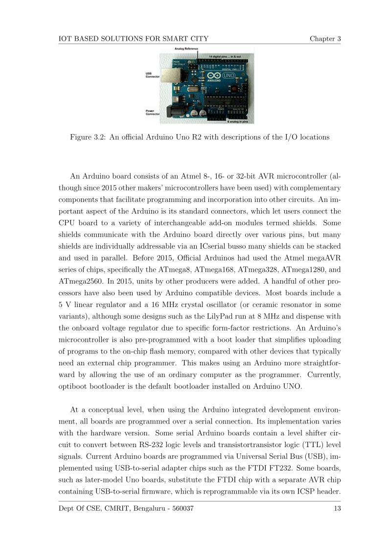
Figure 3.2: An official Arduino Uno R2 with descriptions of the I/O locations
An Arduino board consists of an Atmel 8-, 16- or 32-bit AVR microcontroller (al-
though since 2015 other makers’ microcontrollers have been used) with complementary
components that facilitate programming and incorporation into other circuits. An im-
portant aspect of the Arduino is its standard connectors, which let users connect the
CPU board to a variety of interchangeable add-on modules termed shields. Some
shields communicate with the Arduino board directly over various pins, but many
shields are individually addressable via an ICserial busso many shields can be stacked
and used in parallel. Before 2015, Official Arduinos had used the Atmel megaAVR
series of chips, specifically the ATmega8, ATmega168, ATmega328, ATmega1280, and
ATmega2560. In 2015, units by other producers were added. A handful of other pro-
cessors have also been used by Arduino compatible devices. Most boards include a
5 V linear regulator and a 16 MHz crystal oscillator (or ceramic resonator in some
variants), although some designs such as the LilyPad run at 8 MHz and dispense with
the onboard voltage regulator due to specific form-factor restrictions. An Arduino’s
microcontroller is also pre-programmed with a boot loader that simplifies uploading
of programs to the on-chip flash memory, compared with other devices that typically
need an external chip programmer. This makes using an Arduino more straightfor-
ward by allowing the use of an ordinary computer as the programmer. Currently,
optiboot bootloader is the default bootloader installed on Arduino UNO.
At a conceptual level, when using the Arduino integrated development environ-
ment, all boards are programmed over a serial connection. Its implementation varies
with the hardware version. Some serial Arduino boards contain a level shifter cir-
cuit to convert between RS-232 logic levels and transistortransistor logic (TTL) level
signals. Current Arduino boards are programmed via Universal Serial Bus (USB), im-
plemented using USB-to-serial adapter chips such as the FTDI FT232. Some boards,
such as later-model Uno boards, substitute the FTDI chip with a separate AVR chip
containing USB-to-serial firmware, which is reprogrammable via its own ICSP header.
Dept Of CSE, CMRIT, Bengaluru - 560037 13
IOT BASED SOLUTIONS FOR SMART CITY Chapter 3
Other variants, such as the Arduino Mini and the unofficial Boarduino, use a detach-
able USB-to-serial adapter board or cable, Bluetooth or other methods, when used
with traditional microcontroller tools instead of the Arduino IDE, standard AVR in-
system programming (ISP) programming is used.
The Arduino board exposes most of the microcontroller’s I/O pins for use by other
circuits. The Diecimila,[a] Duemilanove,[b] and current Uno[c] provide 14 digital I/O
pins, six of which can produce pulse-width modulated signals, and six analog inputs,
which can also be used as six digital I/O pins. These pins are on the top of the
board, via female 0.1-inch (2.54 mm) headers. Several plug-in application shields are
also commercially available. The Arduino Nano, and Arduino-compatible Bare Bones
Board[13] and Boarduino[14] boards may provide male header pins on the underside
of the board that can plug into solderless breadboards.
Many Arduino-compatible and Arduino-derived boards exist. Some are function-
ally equivalent to an Arduino and can be used interchangeably. Many enhance the
basic Arduino by adding output drivers, often for use in school-level education, to sim-
plify making buggies and small robots. Others are electrically equivalent but change
the form factor, sometimes retaining compatibility with shields, sometimes not. Some
variants use different processors, of varying compatibility.
3.1.3 DIGITAL PINS
The pins on the Arduino can be configured as either inputs or outputs. This document
explains the functioning of the pins in those modes. While the title of this document
refers to digital pins, it is important to note that vast majority of Arduino (Atmega)
analog pins, may be configured, and used, in exactly the same manner as digital pins.
3.1.4 PROPERTIES OF PINS CONFIGURED AS INPUT
Arduino (Atmega) pins default to inputs, so they don’t need to be explicitly declared
as inputs with pinMode() when you’re using them as inputs. Pins configured this way
are said to be in a high-impedance state. Input pins make extremely small demands
on the circuit that they are sampling, equivalent to a series resistor of 100 megohm
in front of the pin. This means that it takes very little current to move the input pin
from one state to another, and can make the pins useful for such tasks as implement-
ing a capacitive touch sensor, reading an LED as a photodiode, or reading an analog
Dept Of CSE, CMRIT, Bengaluru - 560037 14

IOT BASED SOLUTIONS FOR SMART CITY Chapter 3
sensor with a scheme such as RCTime.
This also means however, that pins configured as pinMode(pin, INPUT) with
nothing connected to them, or with wires connected to them that are not connected to
other circuits, will report seemingly random changes in pin state, picking up electrical
noise from the environment, or capacitively coupling the state of a nearby pin.
3.1.5 PULLUP RESISTOR WITH PINS CONFIGURED
AS INPUT
Often it is useful to steer an input pin to a known state if no input is present. This
can be done by adding a pullup resistor (to +5V), or a pulldown resistor (resistor to
ground) on the input. A 10K resistor is a good value for a pullup or pulldown resistor.
3.1.6 PROPERTIES OF PINS CONFIGURED AS
INPUT PULLUP
There are 20K pullup resistors built into the Atmega chip that can be accessed from
software. These built-in pullup resistors are accessed by setting the pinMode as IN-
PUT PULLUP. This effectively inverts the behavior of the INPUT mode, where HIGH
means the sensor is off, and LOW means the sensor is on. The value of this pullup
depends on the microcontroller used. On most AVRbased boards, the value is guar-
anteed to be between 20k and 50k. On the Arduino Due, it is between 50k and 150k.
For the exact value, consult the datasheet of the microcontroller on your board.
When connecting a sensor to a pin configured with INPUT PULLUP, the other end
should be connected to ground. In the case of a simple switch, this causes the pin to
read HIGH when the switch is open, and LOW when the switch is pressed.
The pullup resistors provide enough current to dimly light an LED connected to a pin
that has been configured as an input. If LEDs in a project seem to be working, but
very dimly, this is likely what is going on.
The pullup resistors are controlled by the same registers (internal chip memory lo-
cations) that control whether a pin is HIGH or LOW. Consequently, a pin that is
configured to have pullup resistors turned on when the pin is an INPUT, will have the
pin configured as HIGH if the pin is then switched to an OUTPUT with pinMode.
This works in the other direction as well, and an output pin that is left in a HIGH
state will have the pullup resistors set if switched to an input with pinMode.
Dept Of CSE, CMRIT, Bengaluru - 560037 15

IOT BASED SOLUTIONS FOR SMART CITY Chapter 3
3.1.7 PROPERTIES OF PINS CONFIGURED AS
OUTPUT
Pins configured as OUTPUT with pinMode() are said to be in a low-impedance state.
This means that they can provide a substantial amount of current to other circuits.
Atmega pins can source (provide positive current) or sink (provide negative current)
up to 40 mA (milliamps) of current to other devices/circuits. This is enough current
to brightly light up an LED (don’t forget the series resistor), or run many sensors, for
example, but not enough current to run most relays, solenoids, or motors.
Short circuits on Arduino pins, or attempting to run high current devices from
them, can damage or destroy the output transistors in the pin, or damage the entire
Atmega chip. Often this will result in a ”dead” pin in the microcontroller but the
remaining chip will still function adequately. For this reason it is a good idea to
connect OUTPUT pins to other devices with 470 or 1k resistors, unless maximum
current draw from the pins is required for a particular.
3.1.8 ADVANTAGES OF USING ARDUINO
• Inexpensive - Arduino boards are relatively inexpensive compared to other mi-
crocontroller platforms. The least expensive version of the Arduino module can
be assembled by hand, and even the pre-assembled Arduino modules cost less
than.
• Cross-platform - The Arduino Software (IDE) runs on Windows, Macintosh
OSX, and Linux operating systems. Most microcontroller systems are limited
to Windows.
• Simple, clear programming environment - The Arduino Software (IDE) is easy-
to-use for beginners, yet flexible enough for advanced users to take advantage of
as well. For teachers, it’s conveniently based on the Processing programming en-
vironment, so students learning to program in that environment will be familiar
with how the Arduino IDE works.
• Open source and extensible software - The Arduino software is published as open
source tools, available for extension by experienced programmers. The language
can be expanded through C++ libraries, and people wanting to understand the
technical details can make the leap from Arduino to the AVR C programming
Dept Of CSE, CMRIT, Bengaluru - 560037 16

IOT BASED SOLUTIONS FOR SMART CITY Chapter 3
language on which it’s based. Similarly, you can add AVR-C code directly into
your Arduino programs if you want to.
• Open source and extensible hardware - The plans of the Arduino boards are
published under a Creative Commons license, so experienced circuit designers
can make their own version of the module, extending it and improving it. Even
relatively inexperienced users can build the breadboard version of the module
in order to understand how it works and save money.
Dept Of CSE, CMRIT, Bengaluru - 560037 17
Chapter 4
SYSTEM REQUIREMENTS
4.0.1 HARDWARE REQUIREMENTS
• Arduino
• LDR
• IR sensors
• Float switch
• Humidity sensors
• PC with wifi
• 2channel relay board
• Android smart phone
4.0.2 SOFTWARE REQUIREMENTS
• Arduino IDE 1.8.5
• Embedded C
• Blynk app 2.24.0
4.0.3 TECHNICAL SPECIFICATION
Microcontroller ATmega328P Operating Voltage 5V Input Voltage(recommended) 7-
12V Input Voltage(limit) 6-20V Digital I/O Pins 14 (of which 6 provide PWM output)
PWM Digital I/O Pins 6 Analog Input Pins 6 DC Current per I/O Pin 20 mA DC
Current for 3.3V Pin 50 mA Flash Memory 32 KB (ATmega328P) of which 0.5 KB
used by bootloader SRAM 2 KB (ATmega328P) EEPROM 1 KB (ATmega328P)
18
IOT BASED SOLUTIONS FOR SMART CITY Chapter 4
Clock Speed 16 MHz LED BUILTIN 13 Length 68.6 mm Width 53.4 mm Weight 25
g
I. Feature High Performance, Low Power AtmelAVR 8-Bit Microcontroller Family
Advanced RISC Architecture
• 131 Powerful Instructions
• Most Single Clock Cycle Execution
• 32 x 8 General Purpose Working Registers
• Fully Static Operation
• Up to 20 MIPS Throughput at 20MHz
• On-chip 2-cycle Multiplier
High Endurance Non-volatile Memory Segments
• 32KBytes of In-System Self-Programmable Flash program
Memory
• 1KBytes EEPROM
• -2KBytes Internal SRAM
• -Write/Erase Cycles: 10,000 Flash/100,000 EEPROM
• Data Retention: 20 years at 85C/100 years at 25C(1)
• Optional Boot Code Section with Independent Lock Bits
• In-System Programming by On-chip Boot Program
• True Read-While-Write Operation
I/O and Packages
• 23 Programmable I/O Lines
• 28-pin PDIP, 32-lead TQFP, 28-pad QFN/MLF and 32-pad QFN/MLF
Operating Voltage:
• 1.8 - 5.5V
Temperature Range:
• -40C to 105CDept Of CSE, CMRIT, Bengaluru - 560037 19

IOT BASED SOLUTIONS FOR SMART CITY Chapter 4
Speed Grade:
• 0 - 4MHz @ 1.8 - 5.5V
• 0 - 10MHz @ 2.7 - 5.5V
• 0 - 20MHz @ 4.5 - 5.5V
Power Consumption at 1MHz, 1.8V, 25C
• Active Mode: 0.2mA
• Power-down Mode: 0.1A
• Power-save Mode: 0.75A (Including 32kHz RTC)
4.0.4 PROTOCOL
In this project we are UART (universal Asynchronous Receiver and Transmitter) Pro-
tocol UART is a simple half-duplex, asynchronous, serial protocol. Simple communi-
cation between two equivalent nodes. Any node can initiate communication. Since
connection is half-duplex, the two lanes of communication are completely independent.
4.0.5 ADVANTAGES OF THE SYSTEM
• It is fast, Reliable.
• The concerned person can monitor and control anywhere in the world.
• Can maintain a hygienic environment by periodically disposing the garbage.
• Lights can be provided to each and every street by checking the status in each
street.
• Smart parking system can be employed thereby reducing traffic congestion.
4.0.6 APPLICATION
Smart homes could be monitored by using the data that are generated by the sensors
By enabling smart parking, arrival and departure of various vehicles can be tracked
for different parking lots distributed in the city Weather and water systems can utilize
some sensors to provide suitable information
Dept Of CSE, CMRIT, Bengaluru - 560037 20

Chapter 5
BLYNK APP
5.1 OVERVIEW
Blynk is a toolset for all makers, badass inventors, designers, teachers, nerds and
geeks who would love to use their smartphones to control electronics like Arduino,
RaspberryPi and similar ones. Weve done all the hard work of establishing internet
connection, building an app and writing hardware code. With Blynk, you simply snap
together an amazing interface from various widgets we provide, upload the example
code to your hardware and enjoy seeing first results in under 5 minutes! It works
perfectly for newbie makers and saves tons of time for evil geniuses.
Blynk will work with all popular boards and shields. We wanted to give you full free-
dom when deciding how to plug Blynk into your existing or new project. You will also
enjoy the convenience of Blynk Cloud. Which is, by the way is free and open-source.
Imagine a prototyping board on your smartphone where you drag and drop buttons,
sliders, displays, graphs and other functional widgets. And in a matter of minutes
these widgets can control Arduino and get data from it.
Blynk is not an app that works only with a particular shield. Instead, it’s been de-
signed to support the boards and shields you are already using. And it works on iOs
and Android.
UPD: Blynk also works over USB. This means you can tinker with the app by con-
necting it to your laptop or desktop while waiting for some internet shield to arrive.
Blynk works over the Internet. So the one and only requirement is that your hardware
can talk to the Internet.
No matter what type of connection you choose - Ethernet, Wi-Fi or maybe this new
ESP8266 everyone is talking about Blynk libraries and example sketches will get you
online, connect to Blynk Server and pair up with your smartphone.
Currently, Blynk libraries work with:
21

IOT BASED SOLUTIONS FOR SMART CITY Chapter 5
Figure 5.1: Blynk architecture
• USB
• Ethernet shield
• WiFi shield
• Arduino with Ethernet
It’s not that easy to take Arduino out of your home network, so we’ve built a Blynk
server. It handles all the authentication and communication, and also keeps an eye
on your board while the smartphone is offline. Blynk server runs on Java and is open-
source. You will be able to run it locally if you really need to. Messaging between
mobile apps , Blynk Server and Arduino is based on a simple, lightweight and fast
binary protocol over TCP/IP sockets.
5.2 CREATING A PROJECT IN BLYNK APP
After downloading the app, create an account and log in. Welcome to Blynk!
Youll also need to install the Blynk Arduino Library, which helps generate the
firmware running on your ESP8266. Download the latest release from Blynks GitHub
repo, and follow along with the directions there to install the required libraries.
Create a Blynk Project
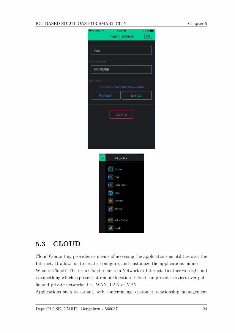
Next, click the Create New Project in the app to create a new Blynk app. Give it
any name you please, just make sure the Hardware Model is set to ESP8266.
The Auth Token is very important youll need to stick it into your ESP8266s
firmware. For now, copy it down or use the E-mail button to send it to yourself.
Dept Of CSE, CMRIT, Bengaluru - 560037 22

IOT BASED SOLUTIONS FOR SMART CITY Chapter 5
Add Widgets to the Project Then youll be presented with a blank new project.
To open the widget box, click in the project window to open.
Add a Button, then click on it to change its settings. Buttons can toggle outputs
on the ESP8266. Set the buttons output to gp5, which is tied to an LED on the Thing
Dev Board. You may also want to change the action to Switch.
Upload the Blynk Firmware File - Examples - Blynk - Boards And Shields menu.
Before uploading, make sure to paste your authoriazation token into the auth[] vari-
able. Also make sure to load your WiFi network settings into the Blynk.begin(auth,
”ssid”, ”pass”) function.
Then click the Run button in the top right corner of the Blynk app. Press the
button and watch the LED!
Then add more widgets to the project. They should immediately work on the
ESP8266 without uploading any new firmware.
Dept Of CSE, CMRIT, Bengaluru - 560037 23
IOT BASED SOLUTIONS FOR SMART CITY Chapter 5
5.3 CLOUD
Cloud Computing provides us means of accessing the applications as utilities over the
Internet. It allows us to create, configure, and customize the applications online.
What is Cloud? The term Cloud refers to a Network or Internet. In other words,Cloud
is something which is present at remote location. Cloud can provide services over pub-
lic and private networks, i.e., WAN, LAN or VPN.
Applications such as e-mail, web conferencing, customer relationship management
Dept Of CSE, CMRIT, Bengaluru - 560037 24

IOT BASED SOLUTIONS FOR SMART CITY Chapter 5
(CRM) execute on cloud. What is Cloud Computing? Cloud Computing refers to ma-
nipulating, configuring, and accessing the hardware and software resources remotely.
It offers online data storage, infrastructure, and application.
Cloud computing offers platform independency, as the software is not required to
be installed locally on the PC. Hence, the Cloud Computing is making our business
applications mobile and collaborative.
Dept Of CSE, CMRIT, Bengaluru - 560037 25

IOT BASED SOLUTIONS FOR SMART CITY Chapter 5
5.3.1 BENEFITSS
Cloud Computing has numerous advantages. Some of them are listed below -
• One can access applications as utilities, over the Internet.
• One can manipulate and configure the applications online at any time.
• It does not require to install a software to access or manipulate cloud application.
• Cloud Computing offers online development and deployment tools, programming
runtime environment through PaaS model.
• Cloud resources are available over the network in a manner that provide platform
independent access to any type of clients.
• Cloud Computing offers on-demand self-service. The resources can be used without
interaction with cloud service provider.
• Cloud Computing is highly cost effective because it operates at high efficiency with
optimum utilization. It just requires an Internet connection.
• Cloud Computing offers load balancing that makes it more reliable.
Dept Of CSE, CMRIT, Bengaluru - 560037 26

IOT BASED SOLUTIONS FOR SMART CITY Chapter 5
5.3.2 CHARACTERSTICS OF CLOUD COMPUTING
There are four key characteristics of cloud computing. They are shown in the following
diagram:
On Demand Self Service - Cloud Computing allows the users to use web services
and resources on demand. One can logon to a website at any time and use them.
Broad Network Access - Since cloud computing is completely web based, it can be
accessed from anywhere and at any time. Resource Pooling - Cloud computing allows
multiple tenants to share a pool of resources. One can share single physical instance
of hardware, database and basic infrastructure. Rapid Elasticity - It is very easy to
scale the resources vertically or horizontally at any time. Scaling of resources means
the ability of resources to deal with increasing or decreasing demand. The resources
being used by customers at any given point of time are automatically monitored. Mea-
sured Service - In this service cloud provider controls and monitors all the aspects of
Dept Of CSE, CMRIT, Bengaluru - 560037 27

IOT BASED SOLUTIONS FOR SMART CITY Chapter 5
cloud service. Resource optimization, billing, and capacity planning etc. depend on it.
Dept Of CSE, CMRIT, Bengaluru - 560037 28

Chapter 6
SENSOR
6.1 LDR
6.1.1 WHAT IS LDR (LIGHT DEPENDENT RESISTOR)
The general purpose photoconductive cell is also known as LDR light dependent re-
sistor. It is a type of semiconductor and its conductivity changes with proportional
change in the intensity of light.
The complete principle of an LDR is as follows. In a semiconductor an energy gap
exists between conduction electrons and valence electrons. As an LDR is also known
as semiconductor photoconductive transducer, when light is incident on it, a photon is
absorbed and thereby it excites an electron from valence band into conduction band.
Due to such new electrons coming up in conduction band area, the electrical resis-
tance of the device decreases. Thus the LDR or photoconductive transducer has the
resistance which is the inverse function of radiation intensity.
Figure 6.1: photoconductive cells
29
IOT BASED SOLUTIONS FOR SMART CITY Chapter 6
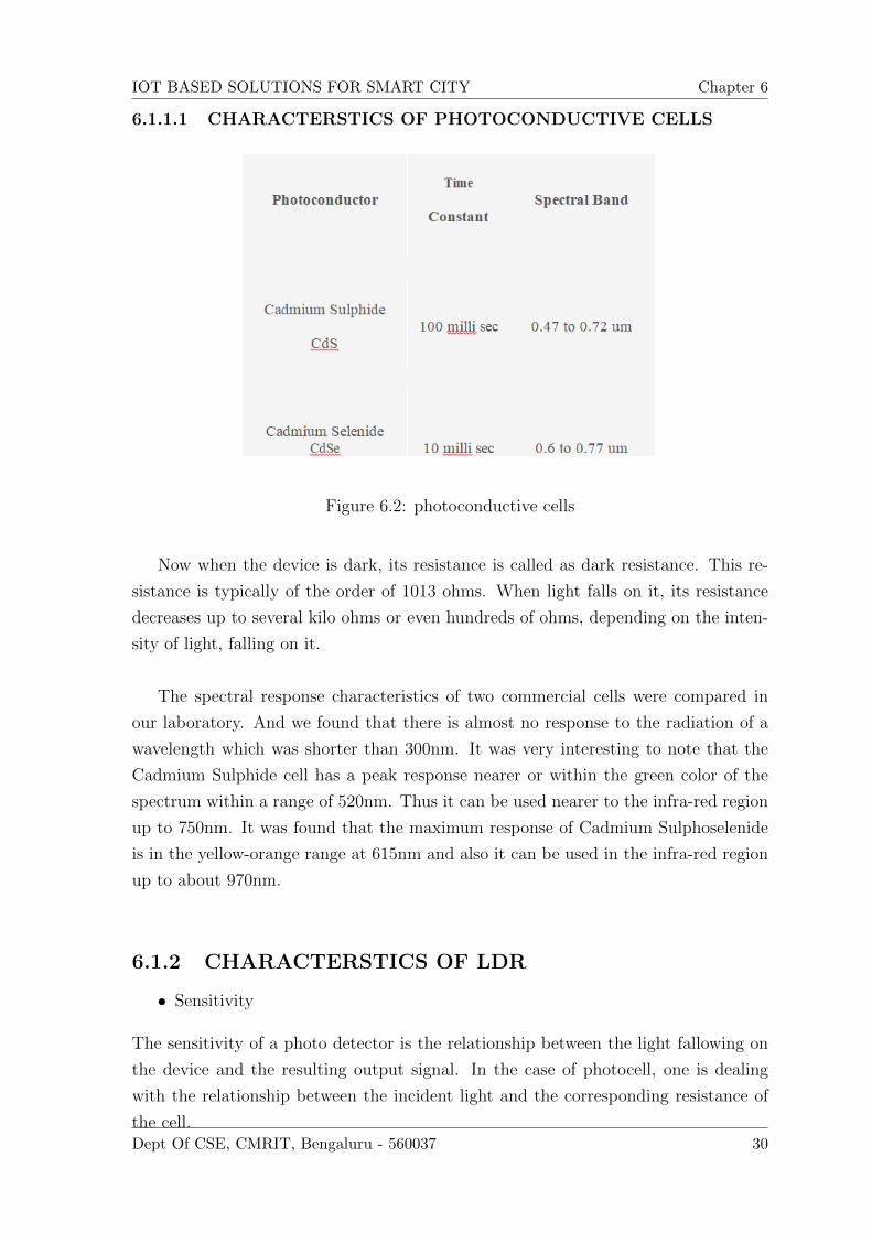
6.1.1.1 CHARACTERSTICS OF PHOTOCONDUCTIVE CELLS
Figure 6.2: photoconductive cells
Now when the device is dark, its resistance is called as dark resistance. This re-
sistance is typically of the order of 1013 ohms. When light falls on it, its resistance
decreases up to several kilo ohms or even hundreds of ohms, depending on the inten-
sity of light, falling on it.
The spectral response characteristics of two commercial cells were compared in
our laboratory. And we found that there is almost no response to the radiation of a
wavelength which was shorter than 300nm. It was very interesting to note that the
Cadmium Sulphide cell has a peak response nearer or within the green color of the
spectrum within a range of 520nm. Thus it can be used nearer to the infra-red region
up to 750nm. It was found that the maximum response of Cadmium Sulphoselenide
is in the yellow-orange range at 615nm and also it can be used in the infra-red region
up to about 970nm.
6.1.2 CHARACTERSTICS OF LDR
• Sensitivity
The sensitivity of a photo detector is the relationship between the light fallowing on
the device and the resulting output signal. In the case of photocell, one is dealing
with the relationship between the incident light and the corresponding resistance of
the cell.Dept Of CSE, CMRIT, Bengaluru - 560037 30

IOT BASED SOLUTIONS FOR SMART CITY Chapter 6
Figure 6.3: Sensitivity graph
Light dependent resistors have a particular property in that they remember the
lightening conditions in which they been stored. This memory effects can be minimized
by storing LDR in light prior to use. Light storage reduces equilibrium time to reach
steady resistance value.
• Spectral Response
Like the human eye, the relative sensitivity of photoconductive cell is depending on
the wave length (color) of the incident light. Each photoconductor material type has
its own spectral unique spectral response curve or plot of the relative response of the
photocell versus wavelength of light.
Figure 6.4: Spectral Response graph
Applications of LDR:
• It is used in burglar alarm to give alarming sound when a burglar invades sen-
sitive premises.
• It is used in street light control to switch on the lights during dusk (evening)
and switch off during dawn (morning) automatically.
Dept Of CSE, CMRIT, Bengaluru - 560037 31

IOT BASED SOLUTIONS FOR SMART CITY Chapter 6
• It is used in Lux meter to measure intensity of light in Lux.
• It is used in photo sensitive relay circuit.
Advantages:
• Wide spectral response
• Low cost
• Wide ambient temperature range
Disadvantages:
• Vary in accurate
• Batch variation can be really large.
6.1.3 IR SENSOR
This project and its circuit are one of the most basic and popular sensor modules.
In electronics, this sensor is analogous to humans visionary senses which can be
used to detect an obstacle which is one of its common applications.
Infrared radiation is the portion of electromagnetic spectrum having wavelengths
longer than visible light wavelengths, but smaller than microwaves, i.e., the region
Figure 6.5: IR Sensor
roughly from 0.75m to 1 m is the infrared region. Infrared waves are invisible to
human eyes. The wavelength region of 0.75m to 3 m is called near infrared, the region
from 3 m to 6 m is called mid infrared and the region higher than 6 m is called far
infrared.
Dept Of CSE, CMRIT, Bengaluru - 560037 32

IOT BASED SOLUTIONS FOR SMART CITY Chapter 6
Break Beam Sensors: This type of sensors consists of a pair of light emitting
and light detecting elements. Infrared source transmits a beam of light towards a
remote IR receiver creating an electronic fence. Once a beam is broken/interrupted
due to some opaque object, output of detector changes and associated electronic
circuitry takes appropriate actions.
Typical applications of such sensors are intrusion detection, shaft encoder (for
measurement of rotation angle/rate of rotation)
Figure 6.6: Break Beam Sensor
Reflectance Sensors: This type of sensors house both an IR source and an IR
detector in a single housing in such a way that light from emitter LED bounces off
an external object and is reflected into a detector. Amount of light reflected into the
detector depends upon the reflectivity of the surface.
Figure 6.7: Reflectance Sensor
This principle is used in intrusion detection, object detection (measure the presence
of an object in the sensors FOV), barcode decoding, and surface feature detection
(detecting features painted, taped, or otherwise marked onto the floor), wall tracking
(detecting distance from the wall), etc.
It can also be used to scan a defined area; the transmitter emits a beam of light
into the scan zone, the reflected light is used to detect a change in the reflected light
thereby scanning the desired zone.
Dept Of CSE, CMRIT, Bengaluru - 560037 33

IOT BASED SOLUTIONS FOR SMART CITY Chapter 6
WATER LEVEL SENSOR
Wide spectrum of sensors is available in the market and commonly, they are classified
based on the specific application of the sensor. Sensor used for measuring humidity is
termed as humidity sensor, the one used for measurement of pressure is called pressure
sensor, sensor used for measurement of displacement is called position sensor and so
on though all of them may be using the similar sensing principle. In a similar fashion,
the sensor used for measurement of fluid levels is called a level sensor.
Quite obvious from its name, level sensors are used to measure the level of the free-
flowing substances. Such substances include liquids like water, oil, slurries, etc as well
as solids in granular/powder form (solids which can flow). These substances tend to
get settled in the container tanks due to gravity and maintain their level in rest state.
Level sensors measure their level against a pre-set reference.
The TMI-2 reactor was destroyed. The cause of the accident was the little mal-
function in the secondary cooling circuit which allowed temperature in the primary
coolant to rise. This caused the reactor to shut down automatically. This situation
developed because the level controls turned off the coolant to the reactor when they
detected presence of cooling water near the top of the tank. The water at the top was
not because of the tank got completely filled, it was because the water was too little
in the tank that it got boiled and swelled up to the top of the tank.
The incident is an example signifying the importance of fluid level sensors and their
proper functioning. They are important not only in nuclear plants but in lot many
applications. Every car, truck and motorcycle is equipped with a fuel level sensor
to measure the amount of gasoline left in the fuel tank. In addition, there are sen-
sors for level measurement of engine oil, brake / power steering fluid, cooling water,
windshield cleaning liquid, etc. Industrial applications include liquid level sensing in
water treatment tanks, transport and storage tanks, in the petrochemical industry
for liquids such as petrol, etc. Liquid level measurement is important in household
applications for devices such as automated coffee machines, water dispensers, juice
squeezers, water evaporators, steamers, fridges and freezers, boilers, heating systems,
dishwashers, washing machines, steam irons, etc.
In short, level sensors are one of the very important sensors and play very im-
portant role in variety of consumer/ industrial applications. As with other type of
sensors, level sensors are available or can be designed using variety of sensing princi-
ples. Selection of an appropriate type of sensor suiting to the application requirement
is very important.
Dept Of CSE, CMRIT, Bengaluru - 560037 34
IOT BASED SOLUTIONS FOR SMART CITY Chapter 6
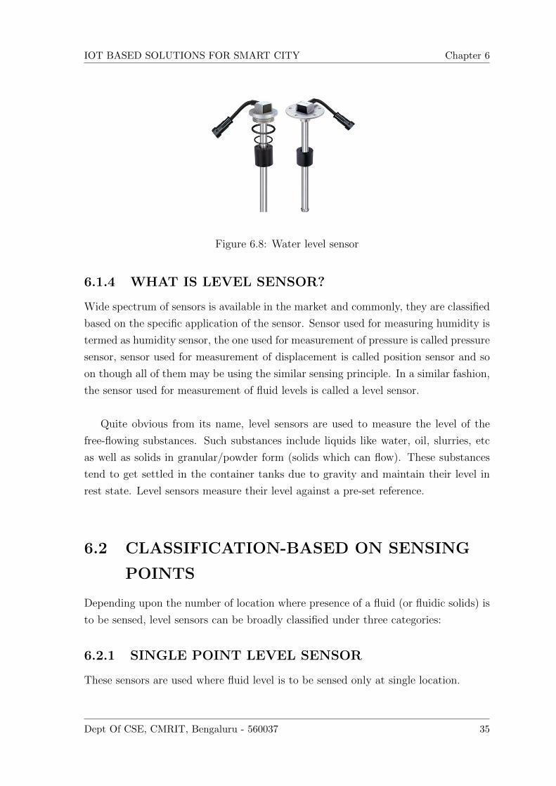
Figure 6.8: Water level sensor
6.1.4 WHAT IS LEVEL SENSOR?
Wide spectrum of sensors is available in the market and commonly, they are classified
based on the specific application of the sensor. Sensor used for measuring humidity is
termed as humidity sensor, the one used for measurement of pressure is called pressure
sensor, sensor used for measurement of displacement is called position sensor and so
on though all of them may be using the similar sensing principle. In a similar fashion,
the sensor used for measurement of fluid levels is called a level sensor.
Quite obvious from its name, level sensors are used to measure the level of the
free-flowing substances. Such substances include liquids like water, oil, slurries, etc
as well as solids in granular/powder form (solids which can flow). These substances
tend to get settled in the container tanks due to gravity and maintain their level in
rest state. Level sensors measure their level against a pre-set reference.
6.2 CLASSIFICATION-BASED ON SENSING
POINTS
Depending upon the number of location where presence of a fluid (or fluidic solids) is
to be sensed, level sensors can be broadly classified under three categories:
6.2.1 SINGLE POINT LEVEL SENSOR
These sensors are used where fluid level is to be sensed only at single location.
Dept Of CSE, CMRIT, Bengaluru - 560037 35

IOT BASED SOLUTIONS FOR SMART CITY Chapter 6
Figure 6.9: Single point level sensor
6.2.2 MULTI POINT LEVEL SENSOR
These sensors are used where fluid level is to be sensed at number of locations single
location
Figure 6.10: Multi point level sensor
6.2.3 CONTINUOS LEVEL SENSOR
These sensors are used where fluid level at all locations is to sensed
Figure 6.11: Continuos level sensor
6.3 CLASSFICATION-BASED ON SENSING
PRINCIPLES
A wide variety of sensing principles are used are used for measurement of liquids,
fluidic solids, slurries, etc. These are explained below
Dept Of CSE, CMRIT, Bengaluru - 560037 36

IOT BASED SOLUTIONS FOR SMART CITY Chapter 6
6.3.1 FLOAT LEVEL SENSOR
In these level sensors, a float moves with the liquid surface. The float is connected
to a core via a spring. A magnetic reed switch is mounted in the hermetically sealed
core and the core moves inside a stem with the float movement. The stem is encircles
by powerful magnets. As the float rises or lowers with liquid level, the reed switch
gets operated due to the magnetic field generated by the magnets.
Figure 6.12: Float level sensor
These sensors are also designed by keeping the stem and the core (with magnetic
reed switch) stationary and making magnets part of the movable float. For multipoint
level sensors multiple magnets/ multiple reed switches (depending upon the design)
are used.
The principle of sensors (floats moving with the liquid level) can be coupled to
dial gauges. Using buoyancy, they can form Visual liquid level indicators.
6.3.2 RESISTIVE LEVEL SENSOR
Variable resistors are widely used in fuel level sensing. A wiper, connected to a lever
arm with a float, moves across continuous resistive track.
The sensor works on potentiometric measuring principle. Current is made to flow
through the resistance. Voltage drops linearly across this resistance. Slider across this
resistance is connected to a float. Voltage output is taken between the slider and one
end of the resistance. Thus with the varying fluid levels, slider moves and the output
voltage varies.
Dept Of CSE, CMRIT, Bengaluru - 560037 37

IOT BASED SOLUTIONS FOR SMART CITY Chapter 6
Figure 6.13: Resistive level sensor
A variant of this type uses conductivity of the liquid under measurement. Current
pulses are sent through a sensor electrode (electrically insulated from the tank or ex-
ternal tube). When sensor electrode is immersed into a conductive liquid, an electrical
connection is created. The electrical potential is proportional to the liquid level and
is measured via a counter-electrode or the tank wall. It is used for continuous filling
level measurement and is suitable for all electrically conductive liquids.
6.3.3 CAPACITIVE LEVEL SENSOR
As capacitance depends upon overlapping area between the plates, distance between
the plates and the dielectric material between the plates, any of the three can be
varies to design a useful capacitive sensor.
One of the simplest capacitive fluid level sensors is shown in figure. It comprises
of two concentric tubes immersed in the fluid whose level is to be measured. Since the
overlapping area between the plates and the distance between the plates is fixed, the
capacitance becomes a function of the dielectric between the plates, i.e., fluid between
the two concentric tubes. As the fluid level changes, the capacitance also changes.
This capacitance becomes the function of the fluid level.
Another variant of this sensor is the one which uses parallel plates instead of
concentric tubes. In this case also, change in the fluid level will change the effective
dielectric constant and so the capacitance between the plates.
Dept Of CSE, CMRIT, Bengaluru - 560037 38

IOT BASED SOLUTIONS FOR SMART CITY Chapter 6
Figure 6.14: Capacitive level sensor1
Figure 6.15: Capacitive level sensor2
6.3.4 PRESSURE BASED LEVEL SENSOR
Pressure is defined as the force per unit area. The pressure at any depth, in a static
fluid is equal to the weight of the liquid acting on a unit area at that depth plus the
pressure acting on the surface of the liquid. Level measurement based on pressure
measurement is also known as hydrostatic tank gauging.
It relies on the principle that the difference between two pressures is equal to the
height of the liquid multiplied by specific gravity. So, force at the bottom of the fluid
container depends only upon the height of the liquid level and therefore, with the
measured hydrostatic pressure and the knowledge of specific gravity of the fluid, level
measurement is performed.
Dept Of CSE, CMRIT, Bengaluru - 560037 39

IOT BASED SOLUTIONS FOR SMART CITY Chapter 6
6.4 ADVANTAGES
• It is fast, Reliable.
• The concerned person can monitor and control anywhere in the world.
• Can maintain a hygienic environment by periodically disposing the garbage.
Dept Of CSE, CMRIT, Bengaluru - 560037 40

Chapter 7
SYSTEM DESGIN
7.1 SYSTEM ARCHITECTURE
A system architecture or systems architecture is the conceptual model that defines
the structure, behaviour, and more views of a system. An architecture description is
a formal description and representation of a system, organized in a way that supports
reasoning about the structures and behaviours of the system.
A system architecture can comprise system components, the externally visible proper-
ties of those components, the relationships (e.g. the behaviour) between them. It can
provide a plan from which products can be procured, and systems developed, that will
work together to implement the overall system. There have been efforts to formalize
languages to describe system architecture; collectively these are called architecture
description languages (ADLs).
Figure 7.1: System architecture
41

IOT BASED SOLUTIONS FOR SMART CITY Chapter 7
7.1.1 DATA FLOW DIAGRAMS
A data flow diagram (DFD) is a graphical representation of the ”flow” of data through
an information system, modelling its process aspects. A DFD is often used as a pre-
liminary step to create an overview of the system, which can later be elaborated.
DFDs can also be used for the visualization of data processing (structured design).
A DFD shows what kind of information will be input to and output from the system,
where the data will come from and go to, and where the data will be stored. It does
not show information about the timing of process or information about whether pro-
cesses will operate in sequence or in parallel.
I LEVEL 0
This level represents the basic flow of data connecting the user to the sensors and
monitoring the water quality.
Figure 7.2: DFD Level 0 Diagram
II.LEVEL 1 This provides a detailed of all the sensors connected.
Figure 7.3: DFD Level 1 Diagram
Dept Of CSE, CMRIT, Bengaluru - 560037 42

IOT BASED SOLUTIONS FOR SMART CITY Chapter 7
III. LEVEL 2 Detailed structure of the Blynk app is given in level 2.
Figure 7.4: DFD Level 2 Diagram
7.1.2 SEQUENCE DIAGRAM
A Sequence diagram is an intaction diagram that shows how processes operate with
one another and in what order. It is a construct of a Message Sequence Chart. A
sequence diagram shows object interactions arranged in time sequence. It depicts the
objects and classes involved in the scenario and the sequence of messages exchanged
between the objects needed to carry out the functionality of the scenario. Sequence
diagrams are typically associated with use case realizations in the Logical View of the
system under development. Sequence diagrams are sometimes called event diagrams
or event scenarios.
A sequence diagram shows, as parallel vertical lines (lifelines), different processes or
objects that live simultaneously, and, as horizontal arrows, the messages exchanged
between them, in the order in which they occur. This allows the specification of sim-
ple runtime scenarios in a graphical manner.
Sequence diagram consists of four objects: I. USER
II. PC
III. CLOUD
IV. BLYNK APP
The user sends the command and the values are displayed on his blynk app and the
various parameters are monitored.
Dept Of CSE, CMRIT, Bengaluru - 560037 43

IOT BASED SOLUTIONS FOR SMART CITY Chapter 7
Figure 7.5: Sequence Diagram
7.1.3 ACIVITY DIAGRAMS
Activity diagrams are graphical representations of workflows of stepwise activities and
actions with support for choice, iteration and concurrency. In the Unified Modeling
Language, activity diagrams are intended to model both computational and organiza-
tional processes (i.e. workflows). Activity diagrams show the overall flow of control.
Activity diagrams are constructed from a limited number of shapes, connected with
arrows. The most important shape types:
• rounded rectangles represent actions;
• diamonds represent decisions;
• bars represent the start (split) or end (join) of concurrent activities;
• a black circle represents the start (initial state) of the workflow;
• An encircled black circle represents the end (final state).
Arrows run from the start towards the end and represent the order in which ac-
tivities happen. Activity diagrams may be regarded as a form of flowchart. Typical
flowchart techniques lack constructs for expressing concurrency. However, the join
and split symbols in activity diagrams only resolve this for simple cases; the meaning
of the model is not clear when they are arbitrarily combined with decisions or loops.
Dept Of CSE, CMRIT, Bengaluru - 560037 44

IOT BASED SOLUTIONS FOR SMART CITY Chapter 7
7.1.4 SUMMARY
This chapter shows the general design and system architecture of the vehicle identi-
fication system. There are also the UML diagrams that include use case diagram to
depict actors and use cases, sequence diagram to show the life line of various activ-
ities and finally the activity diagram that shows the stepwise flow of how the file is
uploaded to file and downloaded by the user.
Dept Of CSE, CMRIT, Bengaluru - 560037 45

Chapter 8
IMPLEMENTATION
8.1 INTRODUCTION
The implementation phase of the project is where the detailed design is actually
transformed into working code. Aim of the phase is to translate the design into a
best possible solution in a suitable programming language. This chapter covers the
implementation aspects of the project, giving details of the programming language
and development environment used. It also gives an overview of the core modules
of the project with their step by step ow. The implementation stage requires the
following tasks:
• Careful planning.
• Investigation of system and constraints.
• Design of methods to achieve the changeover.
• Evaluation of the changeover method.
• Correct decisions regarding selection of the platform.
• Appropriate selection of the language for application development.
8.2 EMBEDDED C
Embedded C is a set of language extensions for the C programming language by the C
Standards Committee to address commonality issues that exist between C extensions
for different embedded systems.
46

IOT BASED SOLUTIONS FOR SMART CITY Chapter 8
8.3 CIRCULT DIAGRAM
Figure 8.1: Block diagram of smart city
8.4 ARDUINO CODE
#inc lude<S o f t w a r e S e r i a l . h> // blynk l i b r a r i e s
#inc lude<BlynkSimpleStream . h>
//#inc lude<SimpleTimer . h>
#d e f i n e BLYNK MAX SENDBYTES 1200
S o f t w a r e S e r i a l DebugSer ia l ( 2 , 3 ) ;
#d e f i n e BLYNK PRINT DebugSer ia l // blynk l i b r a r i e s
char auth [ ]=”0 fc8243f209e427f93199d513e07977d ” ; // authont i ca t i on token
// SimpleTimer t imer ;
i n t i r 1 =4; // input pin c o n f i g u r a t i o n s f o r parking s l o t 1
i n t i r 2 =5; // input pin c o n f i g u r a t i o n s f o r parking s l o t 2
i n t i r 3 =6;// input pin c o n f i g u r a t i o n s f o r dustb ins
i n t i r 4 =7;// input pin c o n f i g u r a t i o n s f o r dustb ins
i n t water =8;// input p ins f o r water l e v e l
i n t humPin = A0;// humidity
i n t l d r p i n =11;// input pin f o r l d r
i n t rPin1 =9; // r e l a y f o r l i g h t
i n t rPin2 =10; // r e l a y f o r pump
/∗ void myTimerEvent ( )
{
Dept Of CSE, CMRIT, Bengaluru - 560037 47

IOT BASED SOLUTIONS FOR SMART CITY Chapter 8
Blynk . v i r tua lWr i t e (V3 ,hum ) ;
}∗/void setup ( )
{// put your setup code here , to run once :
DebugSer ia l . begin ( 9 6 0 0 ) ;
S e r i a l . begin ( 9 6 0 0 ) ;
Blynk . begin ( auth , S e r i a l ) ;
pinMode ( i r1 , INPUT) ;
pinMode ( i r2 , INPUT) ;
pinMode ( i r3 , INPUT) ;
pinMode ( i r4 , INPUT) ;
pinMode (humPin , INPUT) ;
pinMode ( ldrp in , INPUT) ;
pinMode ( water ,OUTPUT) ;
d i g i t a l W r i t e ( water ,HIGH) ;
pinMode ( rPin1 ,OUTPUT) ;
pinMode ( rPin2 ,OUTPUT) ;
// t imer . s e t I n t e r v a l (1000L , myTimerEvent ) ;
}BLYNK WRITE(V6) // l i g h t
{i n t p in s t a t e 1=param . a s In t ( ) ;
d i g i t a l W r i t e ( rPin1 , p in s t a t e1 ) ;
}
BLYNK WRITE(V7) //pump
{i n t p in s t a t e 1=param . a s In t ( ) ;
d i g i t a l W r i t e ( rPin2 , p in s t a t e1 ) ;
}
void loop ( ) {// put your main code here , to run repea t ed ly :
Blynk . run ( ) ;
// t imer . run ( ) ; // I n i t i a t e s BlynkTimer
i n t i r 1 v a l=d ig i ta lRead ( i r 1 ) ; / / parking
Dept Of CSE, CMRIT, Bengaluru - 560037 48

IOT BASED SOLUTIONS FOR SMART CITY Chapter 8
i n t i r 2 v a l=d ig i ta lRead ( i r 2 ) ; / / parking
i f ( i r 1 v a l ==1)
{delay ( 2 0 0 ) ;
Blynk . v i r tua lWr i t e (V0, ” Parking s1 not a v a i l a b l e ” ) ;
// de lay ( 1 0 0 ) ;
}e l s e
{Blynk . v i r tua lWr i t e (V0, ” Parking s1 a v a i l a b l e ” ) ;
// de lay ( 1 0 0 ) ;
}
i f ( i r 2 v a l ==1)
{Blynk . v i r tua lWr i t e (V5, ” Parking s2 not a v a i l a b l e ” ) ;
// de lay ( 1 0 0 ) ;
}e l s e
{Blynk . v i r tua lWr i t e (V5, ” Parking s2 a v a i l a b l e ” ) ;
// de lay ( 1 0 0 ) ;
}
i n t i r 3 v a l=d ig i ta lRead ( i r 3 ) ; // dustb ins
// de lay ( 5 0 0 ) ;
i n t i r 4 v a l=d ig i ta lRead ( i r 4 ) ; / / dustb ins
// de lay ( 5 0 0 ) ;
i f ( i r 3 v a l==0 && i r 4 v a l ==0)
{
Blynk . v i r tua lWr i t e (V1, ” Dustbin i s Empty ” ) ;
// de lay ( 1 0 0 ) ;
}e l s e i f ( i r 3 v a l==1 && i r 4 v a l ==1)
{
Dept Of CSE, CMRIT, Bengaluru - 560037 49

IOT BASED SOLUTIONS FOR SMART CITY Chapter 8
Blynk . v i r tua lWr i t e (V1, ” Dustbin i s Fu l l ” ) ;
// de lay ( 1 0 0 ) ;
}e l s e
{i f ( i r 3 v a l ==1)
{
Blynk . v i r tua lWr i t e (V1, ” Dustbin i s h a l f ” ) ;
// de lay ( 1 0 0 ) ;
}}i n t waterva l=d ig i ta lRead ( water ) ;
// de lay ( 1 0 0 ) ;
i f ( waterva l==1)
{Blynk . v i r tua lWr i t e (V2, ”HIGH” ) ;
d i g i t a l W r i t e ( rPin2 ,LOW) ;
// S e r i a l . p r i n t l n (” Water tank i s Fu l l ” ) ;
de lay ( 1 0 0 ) ;
}e l s e
{Blynk . v i r tua lWr i t e (V2, ”LOW” ) ;
d i g i t a l W r i t e ( rPin2 ,HIGH) ;
// S e r i a l . p r i n t l n (” Water tank i s LOW” ) ;
de lay ( 1 0 0 ) ;
}
i n t hum=analogRead (humPin ) ;
hum = (hum∗5 . 0 )/1024 ; // vo l tage conver s i on
hum=hum∗10 ;
{Blynk . v i r tua lWr i t e (V3 ,hum ) ;
}
Dept Of CSE, CMRIT, Bengaluru - 560037 50
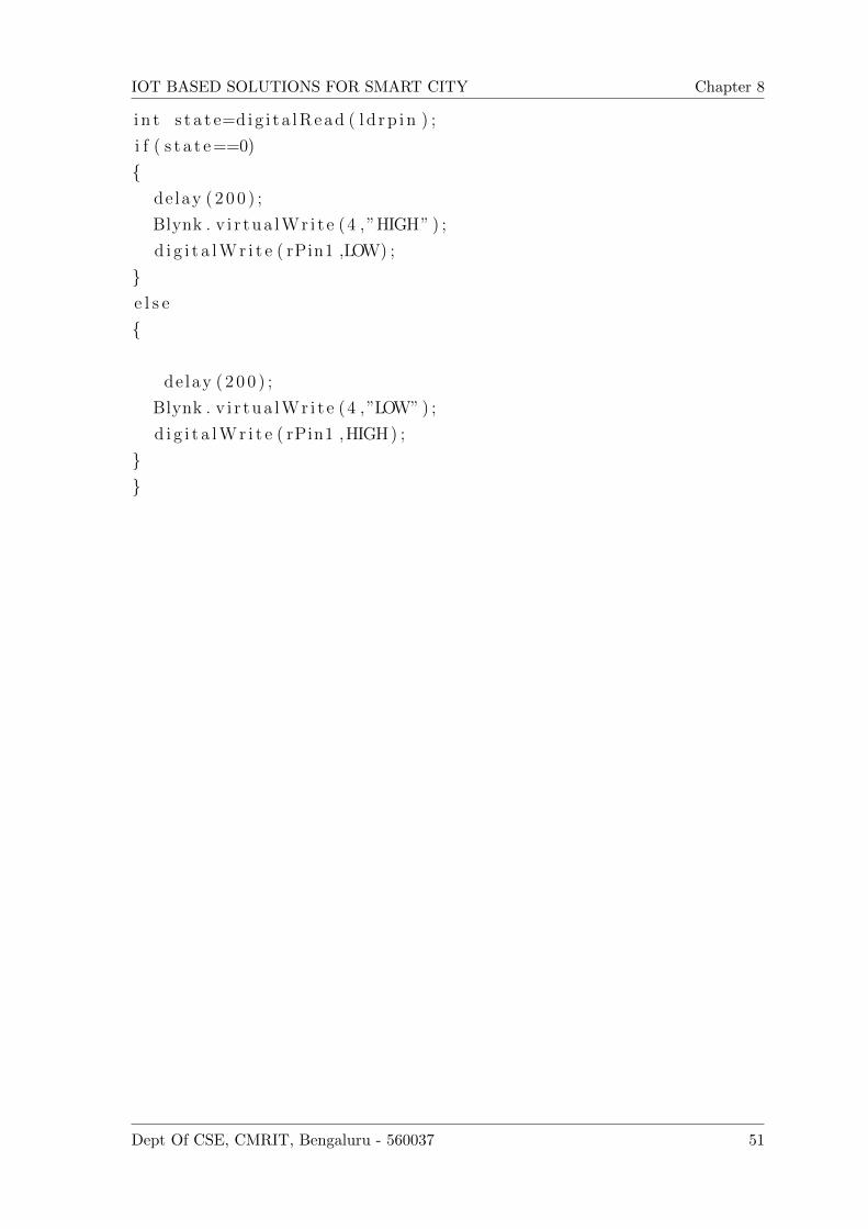
IOT BASED SOLUTIONS FOR SMART CITY Chapter 8
i n t s t a t e=d ig i ta lRead ( l d r p i n ) ;
i f ( s t a t e==0)
{delay ( 2 0 0 ) ;
Blynk . v i r tua lWr i t e (4 ,”HIGH” ) ;
d i g i t a l W r i t e ( rPin1 ,LOW) ;
}e l s e
{
delay ( 2 0 0 ) ;
Blynk . v i r tua lWr i t e (4 ,”LOW” ) ;
d i g i t a l W r i t e ( rPin1 ,HIGH) ;
}}
Dept Of CSE, CMRIT, Bengaluru - 560037 51

Chapter 9
SYSTEM TESTING
9.1 INTRODUCTION
Testing is an important phase in the development life cycle of the product this was
the phase where the error remaining from all the phases was detected. Hence testing
performs a very critical role for quality assurance and ensuring the reliability of the
software. Once the implementation is done, a test plan should be developed and run
on a given set of test data. Each test has a different purpose, all work to verify that all
the system elements have been properly integrated and perform allocated functions.
The testing process is actually carried out to make sure that the product exactly does
the same thing what is suppose to do. Testing is the
nal veri
cation and validation activity within the organization itself. In the testing stage
following goals are tried to achieve.
• To arm the quality of the project.
• To eliminate any residual errors from previous stages.
• To validate the software as the solution to the original problem.
• To provide operational reliability of the system.
During testing the major activities are concentrated on the examination and modi
- cation of the source code. The test cases executed for this project are listed
below. Description of the test case, steps to be followed; expected result, status and
screen- shots are explained with each of the test cases.
52

IOT BASED SOLUTIONS FOR SMART CITY Chapter 9
9.2 TESTING METHODOLOGIES
There are many different types of testing methods or techniques used as part of the
software testing methodology. Some of the important types of testing are:
9.2.1 WHITE BOX TESTING
White Box Testing is a testing in which in which the software tester has knowledge
of the inner workings, structure and language of the software, or at least its purpose.
It is purpose. It is used to test areas that cannot be reached from a black box level.
Using white box testing we can derive test cases that:
• Guarantee that all independent paths within a module have been exercised at
least once.
• Exercise all logical decisions on their true and false sides.
• Execute all loops at their boundaries and within their operational bounds.
• Execute internal data structure to assure their validity.
9.2.2 BLACK BOX TESTING
Black Box Testing is testing the software without any knowledge of the inner workings,
structure or language of the module being tested. Black box tests, as most other kinds
of tests, must be written from a de
nitive source document, such as speci
cation or requirements document, such as speci
cation or requirements document. It is a testing in which the software under test is
treated, as a black box .you cannot see into it. The test provides inputs and responds
to outputs without considering how the software works. It uncovers a different class
of errors in the following categories:
• Incorrect or missing function.
• Interface errors.
• Performance errors.
• Initialization and termination errors.
• Errors in objects. Advantages:
• The test is unbiased as the designer and the tester are independent of each other.
Dept Of CSE, CMRIT, Bengaluru - 560037 53

IOT BASED SOLUTIONS FOR SMART CITY Chapter 9
• The tester does not need knowledge of any speci
c programming languages.
• The test is done from the point of view of the user, not the designer.
• Test cases can be designed as soon as the speci
cations are complete.
9.2.3 UNIT TESTING
Unit testing is usually conducted as part of a combined code and unit test phase of
the software lifecycle, although it is not uncommon for coding and unit testing to be
conducted as two distinct phases. Test strategy and approach Field testing will be
performed manually and functional tests will be written in detail. Test objectives:
• All Components must work properly.
• Proper coordinates should be sent by the Android app to the Arduino.
• entry screen, messages and responses must not be delayed in the Android app.
Figure 9.1: Unit Testing
9.3 TEST CASE 1
Function : Void Loop() - Smart Parking System
Purpose : This function is used to detect a object in front of it.
Preconditions : The object should be detected.
Inputs : Readings from IR sensors.
Dept Of CSE, CMRIT, Bengaluru - 560037 54

IOT BASED SOLUTIONS FOR SMART CITY Chapter 9
Expected Ouput : Displaying information about parking availability and non-availability
in BLYNK application.
9.4 TEST CASE 2
Function : Void Loop() - Smart Dustbin
Purpose : This function is used to detect a obstacle in dustbin.
Preconditions : The object should be detected.
Inputs : Readings from IR sensors.
Expected Ouput : Displaying information about dustbin status in BLYNK applica-
tion.
9.5 TEST CASE 3
Function : Void Loop() - Smart Water Monitoring
Purpose : This function is used to detect a water level and control a pump.
Preconditions : It should detect a level of liquid in water tank.
Inputs : Low or High level of float switch.
Expected Ouput : Control a pump based on High or Low level of water in tank.
9.6 TEST CASE 4
Function : Void Loop() - Smart Street Lights
Purpose : This function is used to detect a absence and presence of light in environ-
ment.
Preconditions : It should sense a absence and presence of light.
Inputs : Readings from LDR sensors.
Expected Ouput : Should switch on and switch-off street lights in absence and pres-
ence of light respectively.
Dept Of CSE, CMRIT, Bengaluru - 560037 55

Chapter 10
RESULTS AND DISCUSSIONS
10.1 DESCRIPTION
Initially,Sensors are used for monitoring various parameters like light availability,water
level.Two IR sensors are used for monitoring the waste level present in the dustbin.
Ultrasonic sensor is used for smart parking. These sensors values are given to the
Arduino. The values are then send to the cloud through Wi-fi connection. The user
can access these values through Blynk app. Along with monitoring the user can also
control some of the parameters like switching on motor, switching on LED. This is
done through the relays connected to the Arduino. The commands are sent through
the Blynk app.
• Smart Parking:When obstacle is detected by ultrasonic sensor,the values are
given to arduino.From arduino to cloud through wifi.Through BLYNK applica-
tion,status of parking will be displayed.
• Street Light:When absense of light is detected in the environment,LDR sen-
sor automatically detected it and switched on the street light.When presence of
light detected in the environment,user can manually monitor the street lights
through BLYNK app.
• Water Level:When water level is low and detected by the float switch in a
tank, automatically water pump will be switched on through relay.When water
level is high,automatically water pump will be switched off.And user can also
monitoring a water level manually through BLYNK app.
56

IOT BASED SOLUTIONS FOR SMART CITY Chapter 10
• Smart Dustbin:When obstacle is detected in the dustbin by IR sensor,those
values are given to arduino,from arduino to cloud through wifi.Status of dustbin
will be displayed in BLYNK application.
10.2 OUTPUTS
Figure 10.1: Overview of Smart City
Dept Of CSE, CMRIT, Bengaluru - 560037 57

IOT BASED SOLUTIONS FOR SMART CITY Chapter 10
Figure 10.2: Parking slot 1 available
Figure 10.3: Parking slot 2 available
Dept Of CSE, CMRIT, Bengaluru - 560037 58

IOT BASED SOLUTIONS FOR SMART CITY Chapter 10
Figure 10.4: Both the parking slots are not available
Figure 10.5: Dustbin is half
Dept Of CSE, CMRIT, Bengaluru - 560037 59

IOT BASED SOLUTIONS FOR SMART CITY Chapter 10
Figure 10.6: Dustbin is full
Dept Of CSE, CMRIT, Bengaluru - 560037 60

IOT BASED SOLUTIONS FOR SMART CITY Chapter 10
Figure 10.7: Street light is on
Dept Of CSE, CMRIT, Bengaluru - 560037 61

IOT BASED SOLUTIONS FOR SMART CITY Chapter 10
Figure 10.8: Overall status of Smart City in BLYNK application
Figure 10.9: Status of parking slot 1 in BLYNK application
Dept Of CSE, CMRIT, Bengaluru - 560037 62
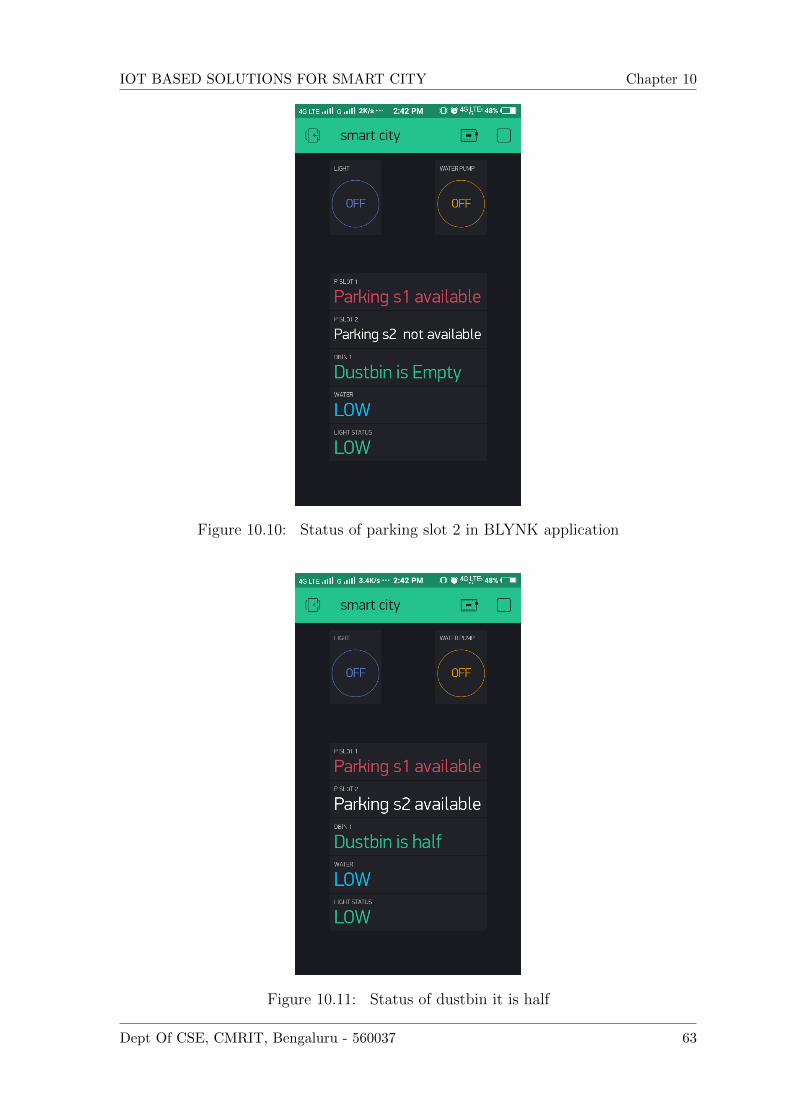
IOT BASED SOLUTIONS FOR SMART CITY Chapter 10
Figure 10.10: Status of parking slot 2 in BLYNK application
Figure 10.11: Status of dustbin it is half
Dept Of CSE, CMRIT, Bengaluru - 560037 63

IOT BASED SOLUTIONS FOR SMART CITY Chapter 10
Figure 10.12: Status of dustbin it is full
Dept Of CSE, CMRIT, Bengaluru - 560037 64

Chapter 11
CONCLUSION AND FUTURE
SCOPE
11.1 CONCLUSION
IOT is setting off an upsurge of information industry. IOT is still in its initial stage.
The hardware of a low-cost module used in IOT enabled systems has been designed
and the concept for the use of this module for Smart City Monitoring and controlling
has been proposed.
11.2 FUTURE SCOPE
The Smart City aims to make optimal and sustainable use of all resources, while main-
taining an appropriate balance between social, environmental and economic costs.
The main categories that define smart cities include the quality of the environment,
energy, water and waste water, transportation and traffic, information and communi-
cation systems, quality of life, government, economics, human resources, housing and
land use, homeland security and emergency preparedness.
65

REFERENCES
[1] J. Gubbi and R. Buyya, Internet of things (IOT): A vision, architectural elements,
and future directions, Future Generation Computer Systems 29, pp. 1645-1660,
2013.
[2] T-Y Chen, H-W Wei, N-L Hsu, and W-K Shih, A IOT application of safe build-
ing in IPV6 network environment, IEEE 37th Annual Computer Software and
Applications Conference, pp. 748-753, 2013.
[3] A. Monzon, Smart cities concept and challenges bases for the assessment of smart
city projects, IEEE Smart cities and Green ICT Systems (SMARTGREENS), pp.
1-11, May 2015.
[4] A. Zanella, N.Bui, A. Castellani, L. Vangelista, and M. Zorzi, Internet of things
for smart cities, Internet of Things Journal, IEEE, pp. 22-32, Feb. 2014.
[5] A. Zelenkauskaite, N. Bessis, S. Sotiriadis, and E. Asimakopoulou, Interconnect-
edness of complex systems of internet of things through social network analysis
for disaster management, Intelligent Networking and Collaborative Systems (IN-
CoS), IEEE, pp.503-508, 2012.
[6] L. Filipponi, A. Vitaletti, G. Landi, V. Memeo, G. Laura, and P.Pucci, Smart
city: An event driven architecture for monitoring public spaces with heteroge-
neous sensors, Sensor Technologies and Applications (SENSORCOMM), IEEE,
pp.281-286, 2010.
66