invited paper towardroboticsensorwebs: … paper towardroboticsensorwebs: algorithms,systems,...
TRANSCRIPT

INV ITEDP A P E R
Toward Robotic Sensor Webs:Algorithms, Systems,and ExperimentsRecent advances in wireless sensor networks and collections of stationary
and mobile sensors including robots are reviewed in this paper,
which also presents novel ideas on system architecture and design.
By Hoam Chung, Member IEEE, Songhwai Oh, Member IEEE,
David Hyunchul Shim, Member IEEE, and S. Shankar Sastry, Fellow IEEE
ABSTRACT | This paper presents recent advances in multiagent
sensing and operation in dynamic environments. Technology
trends point towards a fusion of wireless sensor networks with
robotic swarms of mobile robots. In this paper, we discuss the
coordination and collaboration between networked robotic
systems, featuring algorithms for cooperative operations such
as unmanned aerial vehicles (UAVs) swarming. We have devel-
oped cooperative actions of groups of agents such as probabi-
listic pursuit-evasion game for search and rescue operations,
protection of resources, and security applications. We have
demonstrated a hierarchical system architecture which pro-
vides wide-range sensing capabilities to unmanned vehicles
through spatially deployed wireless sensor networks, highlight-
ing the potential collaboration between wireless sensor net-
works and unmanned vehicles. This paper also includes a short
review of our current research efforts in heterogeneous sensor
networks, which is being evolved into mobile sensor networks
with swarmmobility. In a very essential way, this represents the
fusion of mobility of ensembles with the network embedded
systems, the robotic sensor web.
KEYWORDS | Heterogeneous wireless sensor network; multi-
agent cooperation; robotic swarms
I . INTRODUCTION
The distributed control of multiple autonomous agents has
become a very important research topic since individualagents were rapidly connected to each other through va-
rious communication mediums. Although a centralized
system can be implemented using a simpler structure than
a distributed system, the latter is preferred since a multi-
agent system is more robust against local faults and free
from communication bottlenecks. Without a central
coordinator, however, achieving basic properties such as
stability, coordination, and coverage offers serious chal-lenges, and there have been many proposals and
implementations to control and manage such a system;
see [1]–[5], for example.
A wireless sensor network (WSN) is a relatively new
addition to multiagent systems research. A WSN consists of a
large number of spatially distributed devices with computing
and sensing capabilities, i.e., motes, which form an ad hocwireless network for communication [6]–[8]. Applicationsof WSNs include, but are not limited to, building energy
management [9], environmental monitoring [10], traffic
control [11], manufacturing [12], health services [13], indoor
Manuscript received May 10, 2010; revised February 19, 2011; accepted May 7, 2011.
Date of publication July 14, 2011; date of current version August 19, 2011. This work
was supported by many U.S. government agencies including ARO, AFOSR, DARPA,
and ONR. Particularly, this paper is directly supported by ARO MURI Scalable sWarms
of Autonomous Robots and Mobile Sensors (W911NF-0510219), Heterogeneous
Sensor Webs for Automated Target Recognition and Tracking in Urban Terrain
(W911NF-06-1-0076), and ARL Micro Autonomous Systems and Technology
Collaborative Technology Alliance (MAST-CTA, W91INF-08-2-0004). The work of
H. Chung was supported in part by Monash Engineering New Staff Research Grants.
The work of S. Oh was supported in part by the Basic Science Research Program
through the National Research Foundation of Korea (NRF) funded by the Ministry of
Education, Science and Technology (2010-0013354). The work of D. H. Shim was
supported in part by Korea Agency for Defense Development Grant ADDR-401-101761.
H. Chung is with the Department of Mechanical and Aerospace Engineering, Monash
University, Clayton, Vic. 3800, Australia (e-mail: [email protected]).
S. Oh is with the School of Electrical Engineering and Computer Science and the
Automation and Systems Research Institute (ASRI), Seoul National University, Seoul
151-744, Korea (e-mail: [email protected]).
D. H. Shim is with the Department of Aerospace Engineering, Korea Advanced Institute
of Science and Technology, Daejon 305-701, Korea (e-mail: [email protected]).
S. S. Sastry is with the Department of Electrical Engineering and Computer Science,
University of California Berkeley, Berkeley, CA 94720 USA (e-mail:
Digital Object Identifier: 10.1109/JPROC.2011.2158598
1562 Proceedings of the IEEE | Vol. 99, No. 9, September 2011 0018-9219/$26.00 �2011 IEEE
localization [14], and surveillance [15]. Until mid 2000s, theresearch was focused on the development of devices [16],
[17], wireless communication protocols [18], and distributed
inference algorithms [19], [20], for stationary sensor nodes.
Thanks to the recent advances in microelectromechanical
systems (MEMS) technology, distributed time synchroniza-
tion [21], and ultralow-power processors [22], a sensor node
can have more sensors even on a smaller form factor than
before while consuming less power. The most excitingfeature now being added to the traditional WSN research is
the mobility. Biologically inspired microrobots are now
being developed [23]–[28], and these will provide the ability
to move around environments for active sensing.
This trend creates a new junction where the WSN
technologies meet the distributed control of autonomous
mobile agents, which we call the robotic sensor web (RSW)
in this paper. The cooperative robotic sensor nodes willprovide better sensing coverage with a smaller number of
nodes than stationary sensors while more adaptively
responding to operator commands. However, the RSW
implemented on microrobots or miniature robots offers a
new set of challenges. Given the limitations in size, weight,
and power of small robots, it is understood that individual
platforms will be less capable than larger robots. Compu-
tation, communication, and power are coupled with eachother but available onboard resources will be severely
limited. As a result, it is envisioned that the cooperation
between robotic sensor nodes of multiple scales and types
will be required to achieve mission objectives.
In the Robotics and Intelligent Machines Laboratory at
the University of California Berkeley (UC Berkeley), we
have been working on the operations of autonomous
agents and the various research topics in WSNs.BEkeley AeRobot (BEAR) team was established in 1996
in the laboratory. The team developed fundamental
technologies for rotorcraft-based unmanned aerial vehicles
(UAVs), and achieved its first autonomous hovering in
1999 [29]. Following the success, a Yamaha R50 helicopter
was automated, and a basic waypoint navigation interface
was implemented [30]. The first cooperative behavior
between an autonomous UAV and multiple unmannedground vehicles (UGVs) was demonstrated in the proba-
bilistic pursuit-evasion game setup [31], and showed that
the global-max policy outperforms the local-max policy in
capturing an evader. In early 2000s, multiple Yamaha
helicopters were automated [32], and they were used in
the formation flight experiments, in which two real and
seven virtual helicopters were used [33]. In the following
years, the team has been focusing on multivehiclecoordination and conflict resolution scheme based on
model-predictive control (MPC) algorithms [34]–[38].
Our work in wireless sensor networks was initiated by
the participation in the network embedded systems
technology (NEST) project funded by the Defense
Advanced Research Projects Agency (DARPA). Our
WSN research group has produced many theoretical
and technological breakthroughs in wireless sensornetworks and networked control systems, which include
the distributed control within wireless networks [39],
estimation with intermittent observations [40], and
tracking and coordination using WSNs [41]. In the last
few years, we have been working on heterogeneous
sensor networks (HSNs), which are composed of wireless
sensors with various sensing capabilities and communi-
cation bandwidths.Two groups are now jointly working on the RSWs, and
have been participating in Micro Autonomous Systems
and Technology Collaborative Technology Alliance
(MAST-CTA) [42] since 2008.
In this paper, we first summarize our previous results in
tracking and coordination of multiple agents using WSNs,
and recent progress in HSNs. In Section IV, algorithms for
coordinated control of UAV swarms using the MPCapproach are presented. As our concluding remarks, we
present a short review of ongoing research in RSWs.
II . WIRELESS SENSOR NETWORKS
Multitarget tracking and a pursuit evasion game (PEG)
were demonstrated at the DARPA NEST final experiment
on August 30, 2005. In this section, we summarize
experimental results reported in [41].
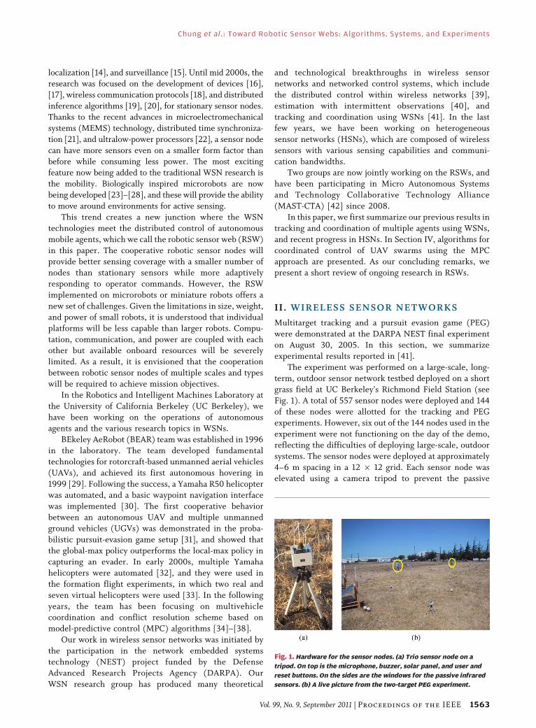
The experiment was performed on a large-scale, long-
term, outdoor sensor network testbed deployed on a shortgrass field at UC Berkeley’s Richmond Field Station (see
Fig. 1). A total of 557 sensor nodes were deployed and 144
of these nodes were allotted for the tracking and PEG
experiments. However, six out of the 144 nodes used in the
experiment were not functioning on the day of the demo,
reflecting the difficulties of deploying large-scale, outdoor
systems. The sensor nodes were deployed at approximately
4–6 m spacing in a 12 � 12 grid. Each sensor node waselevated using a camera tripod to prevent the passive
Fig. 1. Hardware for the sensor nodes. (a) Trio sensor node on a
tripod. On top is the microphone, buzzer, solar panel, and user and
reset buttons. On the sides are the windows for the passive infrared
sensors. (b) A live picture from the two-target PEG experiment.
Chung et al. : Toward Robotic Sensor Webs: Algorithms, Systems, and Experiments
Vol. 99, No. 9, September 2011 | Proceedings of the IEEE 1563
infrared (PIR) sensors from being obstructed by grass anduneven terrain [see Fig. 1(a)]. The true locations of the
nodes were measured during deployment using differential
global positioning system (GPS) and stored in a table at the
base station for reference. However, in the experiments
the system assumed the nodes were placed exactly on a
5-m spacing grid to highlight the robustness of the system
against localization error.
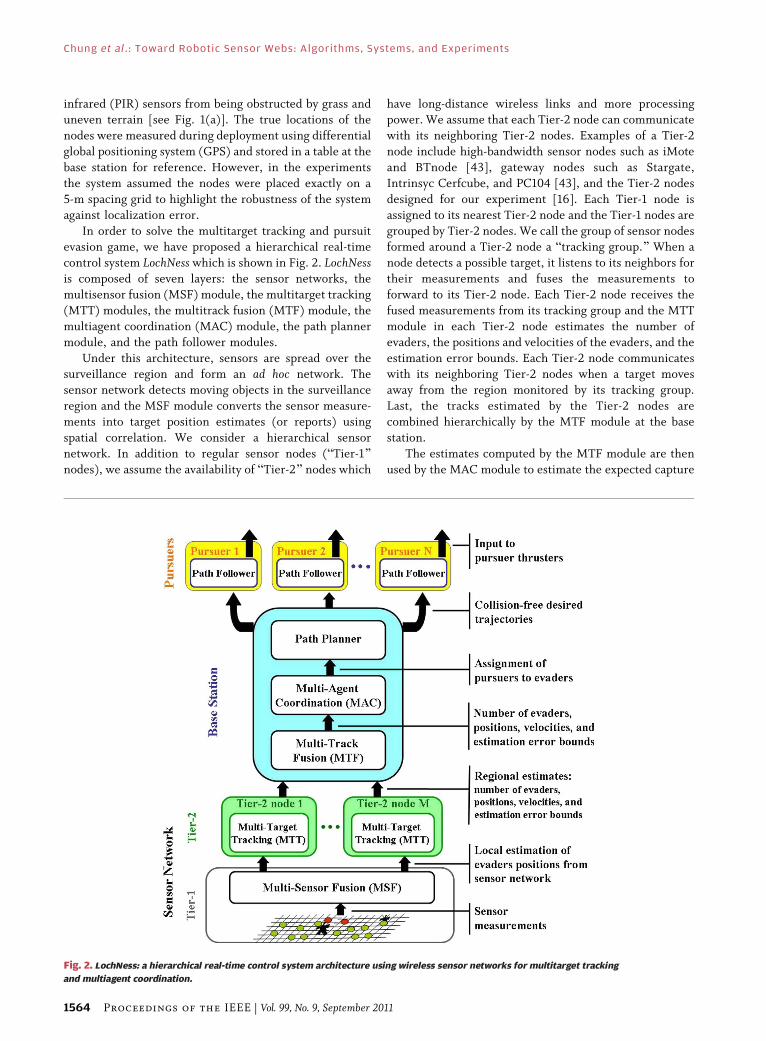
In order to solve the multitarget tracking and pursuitevasion game, we have proposed a hierarchical real-time
control system LochNess which is shown in Fig. 2. LochNessis composed of seven layers: the sensor networks, the
multisensor fusion (MSF) module, the multitarget tracking
(MTT) modules, the multitrack fusion (MTF) module, the
multiagent coordination (MAC) module, the path planner
module, and the path follower modules.
Under this architecture, sensors are spread over thesurveillance region and form an ad hoc network. The
sensor network detects moving objects in the surveillance
region and the MSF module converts the sensor measure-
ments into target position estimates (or reports) using
spatial correlation. We consider a hierarchical sensor
network. In addition to regular sensor nodes (BTier-1[nodes), we assume the availability of BTier-2[ nodes which
have long-distance wireless links and more processingpower. We assume that each Tier-2 node can communicate
with its neighboring Tier-2 nodes. Examples of a Tier-2
node include high-bandwidth sensor nodes such as iMote
and BTnode [43], gateway nodes such as Stargate,
Intrinsyc Cerfcube, and PC104 [43], and the Tier-2 nodes
designed for our experiment [16]. Each Tier-1 node is
assigned to its nearest Tier-2 node and the Tier-1 nodes are
grouped by Tier-2 nodes. We call the group of sensor nodesformed around a Tier-2 node a Btracking group.[ When a
node detects a possible target, it listens to its neighbors for
their measurements and fuses the measurements to
forward to its Tier-2 node. Each Tier-2 node receives the
fused measurements from its tracking group and the MTT
module in each Tier-2 node estimates the number of
evaders, the positions and velocities of the evaders, and the
estimation error bounds. Each Tier-2 node communicateswith its neighboring Tier-2 nodes when a target moves
away from the region monitored by its tracking group.
Last, the tracks estimated by the Tier-2 nodes are
combined hierarchically by the MTF module at the base
station.
The estimates computed by the MTF module are then
used by the MAC module to estimate the expected capture
Fig. 2. LochNess: a hierarchical real-time control system architecture using wireless sensor networks for multitarget tracking
and multiagent coordination.
Chung et al. : Toward Robotic Sensor Webs: Algorithms, Systems, and Experiments
1564 Proceedings of the IEEE | Vol. 99, No. 9, September 2011

times of all pursuer–evader pairs. Based on these
estimates, the MAC module assigns one pursuer to one
evader by solving the bottleneck assignment problem [44]such that the estimated time to capture the last evader is
minimized. Once the assignments are determined, the
path planner module computes a trajectory for each
pursuer to capture its assigned evader in the least amount
of time without colliding into other pursuers. Then, the
base station transmits each trajectory to the path-following
controller of the corresponding pursuer. The path-
following controller modifies the pursuer’s trajectory onthe fly to avoid any obstacles sensed by the pursuer’s
onboard sensors. For the MTT and MTF modules, we used
the online multiscan Markov chain Monte Carlo data
association (MCMCDA) algorithm [45] for solving multi-
target tracking and multitrack fusion problems. It has been
shown that MCMCDA is a fully polynomial randomized
approximation scheme for a single-scan Bayesian data
association problem and MCMCDA approximates theoptimal Bayesian filter when applied to the multiscan
data association problems [45]. For more detail about the
description about the system used in the experiments,
see [41].
We demonstrated the system on one, two, and three
human targets, with targets entering the field at different
times. In all three experiments, the tracking algorithm
correctly estimated the number of targets and produced
correct tracks. Furthermore, the algorithm correctly
disambiguated crossing targets in the two-target andthree-target experiments without classification labels on
the targets. Fig. 3 shows the multitarget tracking results
with three targets walking through the field. The three
targets entered and exited the field around time 10 and 80,
respectively. During the experiment, the algorithm
correctly rejected false alarms and compensated for
missing detections. There were many false alarms during
the span of the experiments. Though not shown in thefigures, the algorithm dynamically corrected previous
track hypotheses as it received more sensor readings.
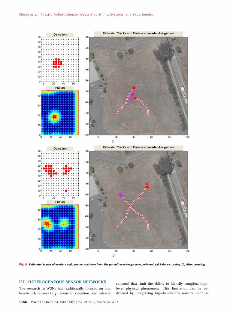
In another demonstration, two simulated pursuers
were dispatched to chase two crossing human targets. The
pursuer-to-target assignment and the robust minimum
time-to-capture control law were computed in real time,
in tandem with the real-time tracking of the targets. The
simulated pursuers captured the human targets, as shownin Fig. 4. In particular, note that the MTT module is able
to correctly disambiguate the presence of two targets
[right panel of Fig. 4(a)] using past measurements,
despite the fact that the multisensor fusion (MSF) module
reports the detection of a single target [upper left panel of
Fig. 4(a)]. A live picture of this experiment is shown on
the right of Fig. 1.
Fig. 3. Estimated tracks of targets at time 70 from the experiment with three people walking in the field. (Upper left) Detection panel. Sensors
are marked by small dots and detections are shown in large disks. (Lower left) Fusion panel shows the fused likelihood. (Right) Estimated tracks
and pursuer-to-evader assignment panel shows the tracks estimated by the MTT module, estimated evader positions (stars) and pursuer
positions (squares). See Fig. 4.
Chung et al. : Toward Robotic Sensor Webs: Algorithms, Systems, and Experiments
Vol. 99, No. 9, September 2011 | Proceedings of the IEEE 1565
III . HETEROGENEOUS SENSOR NETWORKS
The research in WSNs has traditionally focused on low-
bandwidth sensors (e.g., acoustic, vibration, and infrared
sensors) that limit the ability to identify complex, high-
level physical phenomena. This limitation can be ad-
dressed by integrating high-bandwidth sensors, such as
Fig. 4. Estimated tracks of evaders and pursuer positions from the pursuit evasion game experiment. (a) Before crossing. (b) After crossing.
Chung et al. : Toward Robotic Sensor Webs: Algorithms, Systems, and Experiments
1566 Proceedings of the IEEE | Vol. 99, No. 9, September 2011

image sensors, to provide visual verification, in-depth
situational awareness, recognition, and other capabilities.
This new class of WSNs is called heterogeneous sensornetworks (HSNs). The integration of high-bandwidth
sensors and low-power wireless communication in HSNs
requires new in-network information processing techni-
ques and networking techniques to reduce the communi-
cation cost for long-term deployment. The best example of
HSNs is a camera sensor network [46]. Camera sensor
networks (e.g., CITRIC motes [46]; see Fig. 5) can address
the limitations of low-bandwidth sensors by providingvisual verification, in-depth situational awareness, recog-
nition, and other capabilities. The CITRIC mote is a
wireless camera hardware platform with a 1.3 megapixel
camera, a PDA class processor, 64-MB RAM, and 16-MB
FLASH.
CITRIC motes form a wireless network and they must
operate in an uncontrolled environment without human
intervention. In order to fully take advantage of the infor-mation from the network, it is important to know the
position of the cameras in the network as well as the
orientation of their fields of view, i.e., localization. By
localizing the cameras, we can perform better in-network
image processing, scene analysis, data fusion, power hand-
off, and surveillance. While there are localization methods
for camera networks, they all make artificial requirements.
For example, in [47], a common set of static scene featurepoints is assumed to be seen by each set of three cameras. In
[48], the height of the cameras is already known as well as
two orientation parameters. In [20] and [49], a single
object is tracked in a common ground plane and it is already
known how each camera locally maps to the ground plane.
This ground plane concept is extended in [50] and [51] but
the localization problem is solved by using the track of a
single object.We removed these artificial requirements and devel-
oped a camera network localization method that can be
used even when cameras are wide-baseline1 or have
different photometric properties [52]. The method is also
applied to recover the orientations and positions of theCITRIC motes [46]. The method can reliably compute the
orientation of a camera’s view and position only up to a
scaling factor. We removed this restriction by combining
our technique with radio interferometry [53] to recover
the exact orientation and position in [54].
A. Localization Algorithm OverviewWe make no prior assumptions on where the cameras
are placed except that there must be some field-of-view
overlap between pairs of cameras if the orientation, up to a
scaling factor, and position of those cameras are to be
recovered. Furthermore, we do not make any assumptionson known correspondences or about the scene structure.
For example, the cameras may be wide baseline and no
prior knowledge of how each camera’s coordinate frame is
related to the ground of the scene is known.
By observing moving objects in the scene, we localize
the cameras. Our procedure consists of three main steps in
order to use individual raw video streams to localize the
cameras: an intracamera step, an intercamera step, andthen a global recovery step. The intracamera step, which
we call track formation, involves exploiting similarities of
objects between frames for each camera separately. The
intercamera step, which we call track matching, involves
using the object image tracks from each camera as features
to compare against object image tracks from other
cameras. The steps are as follows.
1) Track formation: Find moving objects in eachcamera’s field of view and based on correspon-
dences between frames, build tracks of those
Fig. 5. (a) A CITRIC camera mote. (b) A camera daughter board with major functional units outlined.
1The line connecting the centers of a pair of cameras is called thebaseline.
Chung et al. : Toward Robotic Sensor Webs: Algorithms, Systems, and Experiments
Vol. 99, No. 9, September 2011 | Proceedings of the IEEE 1567

objects within the image plane as shown in Fig. 6.
Multiscan MCMCDA [45] is used to find tracks.
2) Track matching: Use the image tracks from eachcamera as features to compare against image tracks
from another cameras in order to determine the
relative orientation and position of each camera.
This comparison is done in a pairwise manner and
is based on the properties of the essential matrix,
which is computed using the standard algorithm
[55]. This is illustrated in Fig. 7.
3) Global recovery: Transform all relative coordinatesof the cameras into a global coordinate frame.
B. ExperimentVThree-Camera NetworkHere we show the results on data from a camera
network of three cameras. Images from the network can be
seen in Fig. 8. In this setup, three cameras were placed in a
wide baseline configuration on a second story balcony of a
building looking down at the first floor. Tracks of people
walking on the first floor were used to localize the
cameras. Three different sequences of 60 s of video footage
were used. As we had control over the environment,ground truth for the position and orientation of the
cameras was obtained using a point light source and using
the EasyCal Calibration Toolbox [56].
The resulting error in the estimated position, up to a
scaling factor, can be seen in Table 1 and the estimated
orientation error can be seen in Table 2. The center
camera’s coordinate frame was chosen as the world
coordinate frame and the right and left cameras aligned
to the center camera’s coordinate frame in the global
recovery step. It can be seen that the error in theestimation of the localization parameters is small even
though we used the centroids of the objects in the scene to
build the image tracks and then used the estimated track
points to do the correspondence.
C. ExperimentVCITRIC Camera MotesIn this experiment, we positioned two CITRIC motes
8.5 ft apart and pointed them at an open area where people
were walking, as shown by the top row of pictures in Fig. 9.
Each camera mote ran background subtraction on its
current image and then sent the bounding box coordinates
back to the base station for each detected foreground
object. The center of each bounding box was used to buildthe image tracks over time on the base station computer, as
Fig. 8. A three-camera network. Top row: Images from the cameras
with no moving objects. Middle and bottom rows: Images from
cameras with tracks of moving objects shown over time.
TABLE 1 Position Error: The Error in the Estimated Position,
Up to a Scaling Factor, From the Tracks Is Given in Degrees
Between Position Vectors
TABLE 2 Orientation Error: The Error in the Estimated Orientation
From the Tracks Is Given in Degrees Here
Fig. 7. Track matching: (a) shows the tracks in a single camera
(b) shows the tracks from another camera over the same time period,
and (c) shows the correct track matching between the two cameras
that is used in the essential matrix computation.
Fig. 6. Track formation: formation of tracks based on object motion in
two separate cameras. (a) Camera 1. (b) Camera 2.
Chung et al. : Toward Robotic Sensor Webs: Algorithms, Systems, and Experiments
1568 Proceedings of the IEEE | Vol. 99, No. 9, September 2011

shown in Fig. 10. It can be seen that multiple tracks are
successfully estimated from the image sequence.
The localization algorithm then takes these tracks and
performs multiple-view track correspondence. This meth-od is particularly suitable for a low-bandwidth camera net-
work because it works well on wide-baseline images and
images lacking distinct static features [52]. Furthermore,
only the coordinates of the foreground objects need to be
transmitted, not entire images. In implementing the
localization, tracks from the two image sequences are
compared, and we adapt the method such that minimizing
reprojection error determines which tracks best corre-
spond between images. We used 43 frames from thecameras at an image resolution of 640 � 480. Foreground
objects were detected in 22 of the 43 frames and tracks
were built from these detected foreground objects. Four
tracks were built in the first camera and five tracks were
built in the second camera. We were able to determine the
Fig. 9. (Top) Image frames from the left and right camera motes, respectively, viewing the scene. (Bottom) The detected foreground
objects from the scene.
Fig. 10. The tracks of the moving objects in the image planes of the left and right camera motes, respectively, formed by MCMCDA.
Chung et al. : Toward Robotic Sensor Webs: Algorithms, Systems, and Experiments
Vol. 99, No. 9, September 2011 | Proceedings of the IEEE 1569
localization of the two cameras relative to one another with
an average reprojection error of 4.94 pixels (see Fig. 11).
This was based on the matching of four tracks between the
two cameras which minimize the reprojection error.The accuracy of the camera localization estimate is
affected by a few factors. First, the choice of the (low-cost)
camera has an effect on the quality of the captured image.
Second, the precision of the synchronization between the
cameras affects the accuracy of the image correspondence.
Last, we only used a small number of frames to estimate
track correspondence. Using a longer image sequence with
more data points can reduce the estimation error as shownin the next section.
D. ExperimentVFusion-Based Full LocalizationUsing cameras only, we can recover camera positions
only up to a scaling factor. In [54], we described a method
for obtaining full localization, including the scaling factor,
by combining the described camera network localization
method and radio interferometry [53].
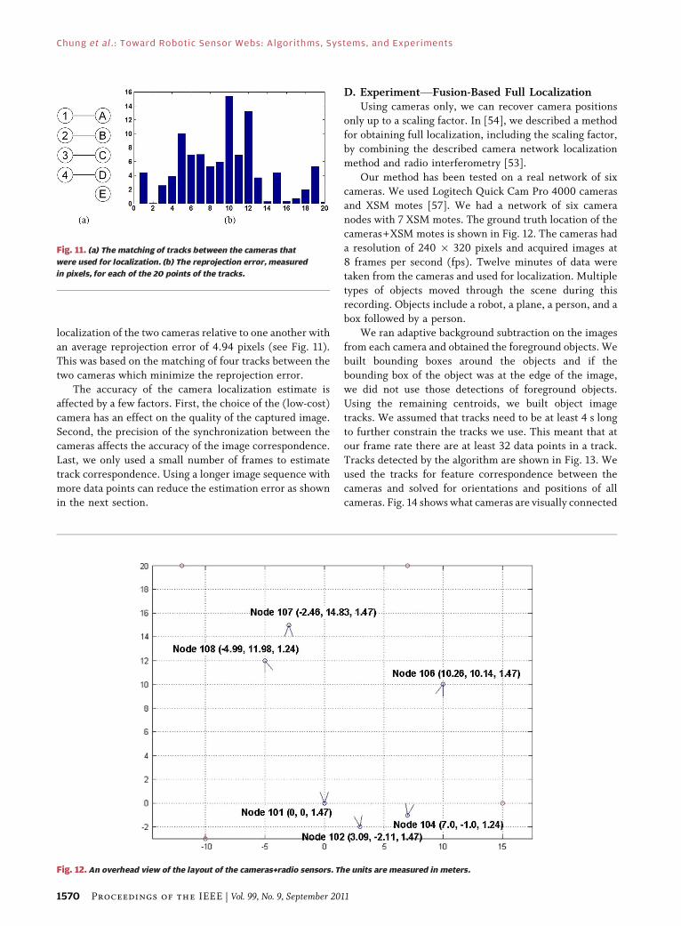
Our method has been tested on a real network of six
cameras. We used Logitech Quick Cam Pro 4000 cameras
and XSM motes [57]. We had a network of six cameranodes with 7 XSM motes. The ground truth location of the
cameras+XSM motes is shown in Fig. 12. The cameras had
a resolution of 240 � 320 pixels and acquired images at
8 frames per second (fps). Twelve minutes of data were
taken from the cameras and used for localization. Multiple
types of objects moved through the scene during this
recording. Objects include a robot, a plane, a person, and a
box followed by a person.We ran adaptive background subtraction on the images
from each camera and obtained the foreground objects. We
built bounding boxes around the objects and if the
bounding box of the object was at the edge of the image,
we did not use those detections of foreground objects.
Using the remaining centroids, we built object image
tracks. We assumed that tracks need to be at least 4 s long
to further constrain the tracks we use. This meant that atour frame rate there are at least 32 data points in a track.
Tracks detected by the algorithm are shown in Fig. 13. We
used the tracks for feature correspondence between the
cameras and solved for orientations and positions of all
cameras. Fig. 14 shows what cameras are visually connected
Fig. 12. An overhead view of the layout of the cameras+radio sensors. The units are measured in meters.
Fig. 11. (a) The matching of tracks between the cameras that
were used for localization. (b) The reprojection error, measured
in pixels, for each of the 20 points of the tracks.
Chung et al. : Toward Robotic Sensor Webs: Algorithms, Systems, and Experiments
1570 Proceedings of the IEEE | Vol. 99, No. 9, September 2011
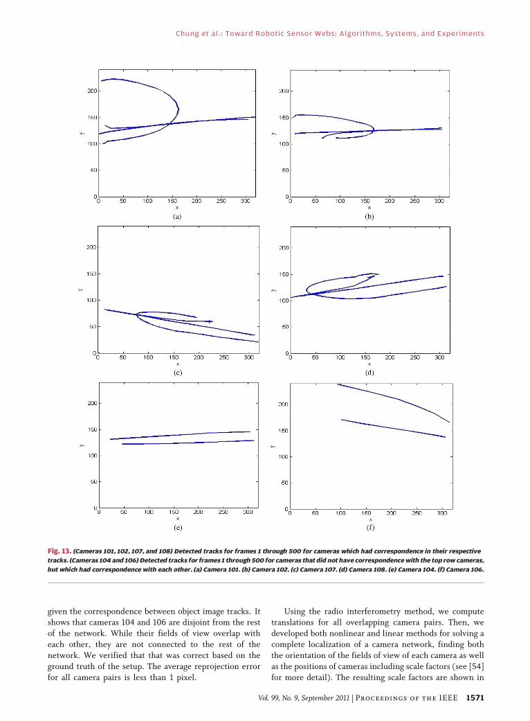
given the correspondence between object image tracks. Itshows that cameras 104 and 106 are disjoint from the rest
of the network. While their fields of view overlap with
each other, they are not connected to the rest of the
network. We verified that that was correct based on the
ground truth of the setup. The average reprojection error
for all camera pairs is less than 1 pixel.
Using the radio interferometry method, we computetranslations for all overlapping camera pairs. Then, we
developed both nonlinear and linear methods for solving a
complete localization of a camera network, finding both
the orientation of the fields of view of each camera as well
as the positions of cameras including scale factors (see [54]
for more detail). The resulting scale factors are shown in
Fig. 13. (Cameras 101, 102, 107, and 108) Detected tracks for frames 1 through 500 for cameras which had correspondence in their respective
tracks. (Cameras 104 and 106) Detected tracks for frames 1 through 500 for cameras that did not have correspondence with the top row cameras,
but which had correspondence with each other. (a) Camera 101. (b) Camera 102. (c) Camera 107. (d) Camera 108. (e) Camera 104. (f) Camera 106.
Chung et al. : Toward Robotic Sensor Webs: Algorithms, Systems, and Experiments
Vol. 99, No. 9, September 2011 | Proceedings of the IEEE 1571

Table 3. It should be noted that the linear method solves
for all scaling factors even if the camera pair does not have
overlapping fields of view.
IV. UAV SWARMS AND MULTIAGENTCOORDINATION
UAVs have been proven as effective and affordable
solutions that complement many operations traditionally
performed by humans. Currently, UAVs are only deployed
in solo missions, managed by a number of well-trained
operators. However, owing to fast technical advances in
navigation, control, and communication, a group of
autonomous mobile agents are expected to executecomplex missions in dynamic situations in the near future.
In such scenarios, a group of autonomous agents will be
able to carry out complex missions as a collective entity so
that, even if some members of the team become
ineffective, the surviving members of the team can still
accomplish the given mission by reallocating tasks to the
surviving members. When deploying a group of UAVs into
the field of action, they should fly without any collisionwith other agents or obstacles, stationary or moving, along
their paths. Planning a collision-free path for single agent
in a perfectly known environment is a well-investigated
problem and there are many efficient algorithms available
[58]. However, solving for collision-free paths for multiple
UAVs in dynamic environment demands replanning
capability literally on the fly by actively taking the latest
sensing information into account. In the following, for thescenarios of deploying a swarm of UAVs in a realistic
environment, we propose a hierarchical structure to guide
a group of vehicles without any collision by combining the
information collected by onboard sensors with geographicinformation database available prior to the mission.
A. System ArchitectureFor swarming scenarios in a complex environment, we
propose a hierarchical system that consists of a global pathplanner as the upper layer and a local trajectory replanner
as the lower layer. In this approach, based on the mapping
information collected prior to a mission, the path planner
initially generates reference trajectories for each vehicle
that lead to the destination without any conflict with
known obstacles. When the agents are deployed, the local
planner on each agent repeatedly solves for a conflict-free
trajectory based on the latest information on the locationsof nearby vehicles and any unexpected obstacles, which is
collected using onboard sensors and intervehicular com-
munication. For trajectory replanning, we propose a
model-predictive approach [35], [36], which solves for a
trajectory that minimizes the cost function that penalizes
the tracking error and the collision with other vehicles and
obstacles over a finite time in the future. The trajectory
replanner resides on each vehicle and computes for acollision-free trajectories using the obstacle information
collected by onboard sensors of its own or from other
vehicles if possible. The proposed system architecture is
illustrated in Fig. 15.
B. MPC FormulationIn this section, we formulate an MPC-based trajectory
planner. Suppose we are given a nonlinear time-invariant
dynamic system such that
xðkþ 1Þ ¼ f xðkÞð Þ þ g xðkÞð ÞuðkÞyðkÞ ¼ h xðkÞð Þ (1)
where x 2 X � Rnx , u 2 U � R
nu . The optimal controlinput sequence over the finite receding horizon N is
obtained by solving the following nonlinear programming
problem:
Find uðkÞ; k ¼ i; iþ 1; . . . ; iþ N � 1
such that uðkÞ ¼ arg min Vðx; k; uÞ (2)
where
Vðx; k; uÞ ¼XkþN�1
i¼k
L xðiÞ; uðiÞð Þ þ F xðkþ NÞð Þ: (3)
Here, L is a positive-definite cost function and F is the
terminal cost. Suppose u�ðkÞ, k ¼ i; . . . ; iþ N � 1, is the
TABLE 3 The Scale Factors for the Distances Between Cameras
Fig. 14. The overlap in fields of view between the camera nodes
based on the object image tracks.
Chung et al. : Toward Robotic Sensor Webs: Algorithms, Systems, and Experiments
1572 Proceedings of the IEEE | Vol. 99, No. 9, September 2011

optimal control sequence that minimizes Vðx; k; uÞ such
that V�ðx; kÞ ¼� Vðx; k; u�ðx; kÞÞ � Vðx; k; uÞ, 8uðkÞ 2 U.
The cost function term L is chosen such that
Lðx; uÞ ¼ 1
2ðxr � xÞTQðxr � xÞ þ 1
2uTRu
þ SðxÞ þXno
l¼1
Pðx; �lÞ: (4)
The first term in (4) penalizes the deviation from the
original trajectory denoted as xr. The second term
penalizes the control input. SðxÞ is the term that penalizes
any states not in X as suggested in [36]. Pðxv; �lÞ is the term
to implement the collision avoidance capability in this
MPC framework. As will be explained in further detailbelow, Pðxv; �lÞ increases with bound as kxv � �lk2 ! 0,
where xv 2 R3 is the position of the vehicle and �l is the
coordinates of the lth obstacle from a total of no obstacles.
During online optimization, the control input can be
enforced to explicitly meet the saturation requirement by
enforcing
uiðkÞ ¼umax
i ; if ui > umaxi
umini ; if ui G umin
i
�(5)
where u ¼� ½u1 . . . unu�T . In this manner, one can find
the control input sequence that will be always within the
physical limit of the given dynamic system. We use the
optimization method based on the indirect method of
Lagrangian multipliers suggested in [59].
C. Obstacle Sensing and Trajectory ReplanningFor a swarming scenario, it is very important to know
where the nearby vehicles are located. Due to the large
number of agents, it is highly desired to sense those usingonboard sensors, not receiving the broadcast information
on a wireless communication channel. Obstacle detection
can be done in either active or passive manner and the
choice depends on many factors including operating
condition, accuracy, and maximum detection range. Laser
scanners measure the distance to an object by precisely
measuring the time of flight of a laser beam to return from
a target. It can be very accurate and straightforward, so it isfavored for 3-D mapping. The detection range depends on
the intensity of the light that radiates from the laser
source. Active radar has similar attributes since it operates
in a similar principle: however, its resolution is much
lower while the detection range can be significantly
longer. Both methods may not be suitable if the mission
should be a covert one. For such cases, vision-based
methods are favored as it is a passive sensing method andcan offer a far greater amount of information if processed
adequately.
For collision avoidance, we choose Pðxv; �lÞ in (4)
such that
Pðxv; �lÞ ¼1
ðxv � �lÞTGðxv � �lÞ þ "(6)
where G is positive definite and " > 0 is to prevent ill
conditioning when kxv � �lk2 ! 0. One can choose
G ¼ diagfgx; gy; gzg, gi > 0, for an orthogonal penalty
function. The penalty function (6) serves as a repelling
Fig. 15. System architecture of a swarming algorithm scenario.
Chung et al. : Toward Robotic Sensor Webs: Algorithms, Systems, and Experiments
Vol. 99, No. 9, September 2011 | Proceedings of the IEEE 1573

potential field and has nonzero value for entire state
space even when the vehicle is far enough from obstacles.The key advantage over conventional potential field
approach here is that we optimize over a finite receding
horizon, not only for the current time as in the potential
field approach. For obstacle avoidance, we consider two
types of scenarios: 1) a situation when the vehicle needs
to stay as far as possible from the obstacles even if no
direct collision is anticipated and 2) a situation when the
vehicle can be arbitrarily close to the obstacle as long asno direct conflict is caused. For the second situation, one
can choose to enable (6) only when kxv � �lk2 G �min,
where �min is the minimum safety distance from other
vehicles.
Since MPC algorithms optimize over a receding finite
horizon into the future, for moving obstacles, their
predicted trajectories over k ¼ i; iþ 1; . . . ; iþ N � 1; are
needed in (6). It is observed that the inclusion of predicted
obstacle locations in the optimization will produce more
efficient evasion trajectory provided that the prediction isreasonably accurate. The simplest yet reasonable estima-
tion is the extrapolation using the current position and
velocity over the prediction horizon such that
�lðkþ iÞ ¼ �lðkÞ þ�tvlðkÞði� 1Þ: (7)
It is noted that the prediction can be done in more
elaborated manners using a Kalman filter, exploiting any
knowledge on the motion of obstacles if available.
D. Experiment Results
1) Intervehicular Collision Avoidance: As the first logical
step, we consider an exemplary scenario of two UAVs
Fig. 16. Midair collision avoidance between two rotorcraft UAVs using real-time MPC and the trajectories of two helicopters.
Chung et al. : Toward Robotic Sensor Webs: Algorithms, Systems, and Experiments
1574 Proceedings of the IEEE | Vol. 99, No. 9, September 2011

exercising identical evasion strategies to demonstrate theviability of the proposed algorithm in real situations. The
proposed algorithm was implemented on MATLAB
Simulink and tested on a team of two helicopter UAVs.
The detailed specifications and architecture are explained
in [35]. In this experiment, Simulink was configured to
run in real time and sent the trajectory commands over a
radio link so that the UAVs followed the designated path
by the onboard flight controller. The vehicles broadcasttheir location using GPS to the ground station, where the
MPC-based trajectories were generated in a centralized
manner. The experiment result is shown in Fig. 16. Two
vehicles are configured to fly towards each other following
a head-on collision course. In this particular case, the
vehicles are constrained to make evasive moves only in the
horizontal plane as a safety measure although the
proposed algorithm is fully capable of vertical evasion aswell. Both vehicles are also executing the same evasive
algorithm. As can be seen from Fig. 16, the vehicles are
able to pass by each other with a sufficient safety
clearance.
2) Obstacle Avoidance: As a next step, we consider an
autonomous exploration problem in an urban environ-
ment, which was simulated by a field with portablecanopies (3 � 3 � 3 m3). They were arranged as shown in
the picture in Fig. 17. The distance between the
neighboring canopies was set to 10–12 m so that the test
UAV with 3.5-m-long fuselage could pass between the
canopies with minimal safe clearance, about 3 m from the
rotor tip to the nearby canopy when staying on course.
For validation, the MPC engine developed in [36] was
applied to the proposed urban experiment setup. Asimulation model was constructed in MATLAB/Simulink,
where the local map building with a laser scanner was
substituted with a preprogrammed map. The MPC
algorithm with the local map building algorithm was
implemented in C language for computation speed and
portability. For this experiment, the Simulink model used
in the collision avoidance was modified and ran for real-
time trajectory generation at 10 Hz.As shown in Fig. 17, the MPC path planner is capable of
generating a collision-free trajectory around the buildings
based on the original trajectory, which intentionally
intersects with some buildings.
Urban exploration experiments were performed using
the same Berkeley UAV testbed used in the intervehicular
collision avoidance experiment. This time, for obstacle
detection, the vehicle was equipped with an LMS-200 fromSick AG, a 2-D laser range finder. It offers maximum 80-m
scanning range with 10-mm resolution and weighs 4.5 kg.
The measurement was sent to the flight computer via
RS-232 and then relayed to the ground station running the
MPC-based trajectory generator in Simulink. The laser
scanner data were then processed following the method
proposed in Section IV-B. In Fig. 18, a 3-D rendering from
the ground station software is presented. The display showsthe location of the UAV, the reference point marker, to a
point in the local obstacle map at that moment, and laser-
scanned points as blue dots. During the experiments, the
laser scanner used in our experiment demonstrated its
capability to detect the canopies in the line of sight with
great accuracy, as well as other surrounding natural and
artificial objects including buildings, trees, and power
lines.The processed laser scanned data in a form of local
obstacle map were used in the optimization (2) to generate
a trajectory using the algorithm in Section IV-C. The
trajectory was then sent via IEEE 802.11b to the avionics
system with a dedicated process running to enforce the
Fig. 18. A snapshot of 3-D rendering during an urban
exploration experiment.
Fig. 17. Aerial view of urban navigation experiment (dashed: given
straight path, solid: actual flight path of UAV during experiment).
Chung et al. : Toward Robotic Sensor Webs: Algorithms, Systems, and Experiments
Vol. 99, No. 9, September 2011 | Proceedings of the IEEE 1575

command update rate at 10 Hz. The tracking control layerenabled the host vehicle to follow the given trajectory with
sufficient distance. In a series of experiments, the vehicle
was able to fly around the obstacles with sufficient
accuracy for tracking the given trajectory, as shown in
Fig. 17 (red line).
E. Cooperative Multiagent CoordinationThe pursuit-evasion game is a probabilistic game
scenario, whose goal is to Bcatch,[ in a finite time, evaders
in a given field with pursuers, which are commanded bysome pursuit algorithms. The initial locations of evaders
are unknown. The pursuers build probabilistic maps [31] of
the possible locations of evaders using their sensing
devices, which are typically vision based. In this scenario,
the group of pursuers, consisting of UAVs and/or UGVs, is
required to go to the requested waypoints, take measure-
ments of the location of themselves and of any evaders
within its detection range, and report the measurement aswell as their current locations. This measurement is used
Fig. 19. A PEG between one pursuer and one evader (�: evader; �: pursuer; background: probabilistic map; darker region represents a
higher probability for capturing the evader).
Chung et al. : Toward Robotic Sensor Webs: Algorithms, Systems, and Experiments
1576 Proceedings of the IEEE | Vol. 99, No. 9, September 2011

to compute the waypoint of pursuers at next time frameand sent to the pursuers via wireless communication for
tracking. In the experiment setup, the PEG algorithm was
implemented in MATLAB/Simulink in a similar manner
with the previous experiments.
In Fig. 19, a result from a PEG game with one aerial
pursuer versus one ground evader is shown. It is noted that
the number of participating pursuers and evaders can be
easily changed although only one pursuer and one evaderexist in this example to maximize the role of the aerial
pursuer UAV. When the game starts, the UAV maintains
hover, waiting for the starting signal from the PEG server.
The ground robot roams in the given field of 20 m � 20 m.
The graph shows two trajectories: one for the pursuer UAV
and the other for the evader UGV. The snapshots in Fig. 19
show the progress of PEG in time. Along with the
trajectories, it also shows the probabilistic map shown asthe gray-scale background and the visibility region denoted
as a square. The evader is caught in 133 s after the game is
started.
F. Towards a Swarm of UAVs inCluttered Environment
In order to evaluate the proposed hierarchical system
for swarming of UAVs, we consider a scenario where 16
UAVs are to be deployed into an urban environment.
Fig. 20 shows an aerial photograph of Fort Benning, GA,
where the scenario takes place. The geometry of buildingsand their locations are known a priori. In this area, some
of corridors that the UAVs are required to fly through areas narrow as 5 m. Therefore, the scenario calls for small-
size rotorcraft UAVs that can fit into the area and fly
slowly and accurately enough. In this scenario, 16 heli-
copter UAVs are initially flying in a four by four forma-
tion, toward the designated cells. Then, they divide into
three subgroups. Some of these subgroups ingress into the
area below the roof line (teams A and C) between the
buildings while others fly over the roof top (team B).For this scenario, the path planner computes initial
paths that are clear from the buildings, but not necessarily
from other agents. In fact, if we were to consider the
intervehicular conflict at the initial planning, the compu-
tation can be not only heavy due to numerical iterations
computing an optimal solution but also not useful at all if
any vehicle deviates from the initial planning due to any
unforeseen events occurring. The model-predictive layerplays an important role here when such events occur; the
online trajectory layer solves for a safe trajectory by
minimizing the cost function that penalizes the near-
collision conditions.
The simulation was also implemented using MATLAB
and Simulink. Sixteen Simulink blocks of a detailed
helicopter model with 15 state variables and nonlinear
kinematics matched with a MPC solver were built and ranin parallel during the simulation. The vehicles’ positions
were shared among the 16 blocks, assuming the existence
of a communication channel that broadcast the position
information at the sampling rate of 25 Hz, which was
deemed rather fast in reality. We imposed a 30-m sensing
limit of other agents. Since the model-predictive algorithm
was numerically heavy, it was implemented using the
CMEX feature of Simulink to speed up. The core algorithmwas constructed to be compatible with CMEX and the
flight control software in C/C++ so that the code validated
in MATLAB could be readily ported into the actual flight
software. Test results show that the implemented model-
predictive algorithm is capable of running in real time on a
Pentium III 700-MHz core of an industrial PC board
known as PC-104 [60].
The simulation result is given in Fig. 21. Initially, thehelicopter UAVs fly at 10 m/s in a loose four by four
formation [Fig. 21(a)] where the trajectory generator only
considers the tracking of the reference path segment
generated by the path planner offline and the collision
avoidance with other agents. Then, just before they enter
the town, they are divided into three subgroups. This
behavior is achieved by generating a common reference
path for each team. The collision-aware tracking capabilitycommands each vehicle to divide into three subgroups
without any collision [Fig. 21(c)]. As they approach the
area with fixed obstacles, i.e., the buildings, the collision
avoidance term (7) in (2) begins to increase. In this
simulation, since the algorithm is fully decentralized, the
vehicles sometimes show Bshopping mob[-like behavior:
as one vehicle is about to enter the corridor, due to the
Fig. 20. An aerial photograph of Fort Benning, GA. UAVs in
three teams are commanded to fly to the designated cells
marked with a serial number.
Chung et al. : Toward Robotic Sensor Webs: Algorithms, Systems, and Experiments
Vol. 99, No. 9, September 2011 | Proceedings of the IEEE 1577

collision avoidance cost, it is pushed away by followingvehicles from the opening of the corridor while the
followers succeed to enter the corridor. This observation
suggests a coordination among neighboring UAVs may be
necessary for more efficient deployment. In Fig. 21(f),
all UAVs arrive at their destinations without any
collision.
G. External Active-Set Methods for ConstrainedMPC-Based Guidance
Modeling obstacles as potential functions described in
the previous sections is more convenient to implement,and it enables a decentralized computation scheme.
However, it suffers from a scaling issue when there are
too many obstacles, therefore too many potential func-
tions, to be considered in the objective function (4). Also,
in applications where safety is critical, regarding the
collision avoidance as explicit state-space constraints is
preferable.
The optimal control problems with state-space con-straints for MPC-based guidance of vehicles are charac-
terized by large numbers of collision avoidance
inequalities and by expensive evaluations of the gradients
of these inequality-defining functions. Since potential
collisions are confined to relatively short segments of the
UAV trajectories, most of the collision avoidance inequal-
ities are inactive. In the case of UAVs, the sampling
intervals are short and hence the viability of the MPCscheme is largely determined by the speed of the nonlinear
programming solvers.
Unfortunately, most standard nonlinear programming
packages, including the excellent set found in TOMLAB
[61], including SNOPT [62], NPSOL [63], and
Schittkowski SQP [64], are not designed to exploit the
fact that a problem with a large number of nonlinear
inequality constraints may have few active constraints.Based on these observations, we have developed an
accelerator scheme for general nonlinear programming
packages, based on the theory of outer approximations
(see [65, p. 460]), which acts as an external active
constraint set strategy for solving nonlinear programming
problems with a large number of inequality constraints.
This strategy constructs a finite sequence of inequality
constrained nonlinear programming problems, containinga progressively larger subset of the constraints in the
original problem, and submits them to a nonlinear
programming solver for a fixed number of iterations.
We have proved that this scheme computes a solution of
the original problem and showed, by means of numerical
experiments, that when applied to a finite-horizon
optimal control problem (FHOCP) with a large number
of state-space constraints, this strategy results in reduc-tions in computing time ranging from a factor of 6 to a
factor of over 100.
Fig. 21. Simulation result of a swarming into an urban area shown in Fig. 20. (a) t ¼ 0; (b) t ¼ 11.4; (c) t ¼ 31.2; (d) t ¼ 45.3; (e) t ¼ 56.9;
(f) t ¼ 73.1.
Chung et al. : Toward Robotic Sensor Webs: Algorithms, Systems, and Experiments
1578 Proceedings of the IEEE | Vol. 99, No. 9, September 2011

In the following, we apply our external active-setmethod to the MPC-based guidance of multiple UAVs with
collision avoidance and no-flight zone constrains, and
show the effectiveness of our scheme.
1) External Active-Set Algorithm: Consider the inequality
constrained minimization problem
Pq : min f 0ð�Þjf jð�Þ � 0; j 2 q� �
(8)
where � 2 Rn, and q ¼� f1; . . . ; qg. We assume that
functions f j : Rn ! R are at least once continuously
differentiable. In the context of discrete optimal control
problems, � can be either a discretized control
sequence or an initial state–discretized control sequence
pair.2
Next we define the index set q�ð�Þ with � > 0 by
q�ð�Þ ¼�
j 2 qjf jð�Þ � þð�Þ � �� �
(9)
where
ð�Þ ¼� maxj2q
f jð�Þ (10)
and
þð�Þ ¼� max 0; ð�Þf g: (11)
Definition IV.1: We say that an algorithm defined by a
recursion of the form
�kþ1 ¼ Að�kÞ (12)
for solving inequality constrained problems of the form (8)
is convergent if any accumulation point of a sequence
f�ig1i¼0, constructed according to the recursion (12), is a
feasible stationary point.Finally, we assume that we have a convergent algorithm
for solving inequality constrained problems of the form (8),
represented by the recursion function AðÞ, i.e., given a
point �k the algorithm constructs its successor �kþ1
according to the rule (12).
Algorithm IV.1
Active-Set algorithm for inequality constrained minimiza-tion problems.
Data: �0, � > 0, Niter 2 N
Step 0: Set i ¼ 0, Q0 ¼ q�ð�0Þ.Step 1: Set �0 ¼ �i and perform Niter iterations of the
form �kþ1 ¼ Að�kÞ on the problem
PQimin f 0ð�Þjf jð�Þ � 0; j 2 Qi
� �(13)
to obtain �Niterand set �iþ1 ¼ �Niter
.
Step 2: Compute ð�iþ1Þ.if �Niter
is returned as a global, local, or stationary
solution of PQiand ð�iþ1Þ � 0, then
STOP
else
Compute
Qiþ1 ¼ Qi [ q�ð�iþ1Þ (14)
and set i ¼ iþ 1, and go to Step 1.
end if
In [38], we have shown that the stationary point
computed by Algorithm IV.1 is also a stationary point ofthe original problem, which is summarized in the
following theorem.
Theorem IV.1: Suppose that the problem Pq has feasible
solutions, i.e., there exist vectors �� such that f jð��Þ � 0
for all j 2 q.
a) If Algorithm IV.1 constructs a finite sequence
f�igki¼0, exiting in Step 2, with iþ 1 ¼ k, then �k
is a global, local, or stationary solution for Pq,
depending on the exit message from the solver
defined by AðÞ.b) If f�ig1i¼0 is an infinite sequence constructed by
Algorithm IV.1 in solving Pq, then any accumu-
lation point3 � of this sequence is feasible and
stationary for Pq.
Although the above theorem guarantees that ouralgorithm converges to a stationary solution of the original
problem, it does not tell much about its performance when
it is used in an MPC scheme. In [38], we showed that our
algorithm reduced the computation time dramatically in
solving a state-constrained FHOCP.
2See [66, Ch. 4] for a detailed treatment of discrete time optimalcontrol problems.
3A point � is said to be an accumulation point of the sequence f�ig1i¼0
if there exists an infinite subsequence, indexed by K � N, f�igi2K , suchthat �i �!
K� as i �!K 1
Chung et al. : Toward Robotic Sensor Webs: Algorithms, Systems, and Experiments
Vol. 99, No. 9, September 2011 | Proceedings of the IEEE 1579
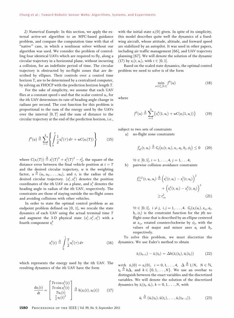
2) Numerical Example: In this section, we apply the ex-ternal active-set algorithm to an MPC-based guidance
problem, and compare the computation time with that of
Bnative[ case, in which a nonlinear solver without our
algorithm was used. We consider the problem of control-
ling four identical UAVs which are required to fly, along a
circular trajectory in a horizontal plane, without incurring
a collision, for an indefinite period of time. The circular
trajectory is obstructed by no-flight zones that are de-scribed by ellipses. Their controls over a control time
horizon Ts are to be determined by a centralized computer,
by solving an FHOCP with the prediction horizon length T.
For the sake of simplicity, we assume that each UAV
flies at a constant speed v and that the scalar control ui, for
the ith UAV determines its rate of heading angle change in
radians per second. The cost function for this problem is
proportional to the sum of the energy used by the UAVsover the interval ½0; T� and the sum of distance to the
circular trajectory at the end of the prediction horizon, i.e.,
f 0ðuÞ ¼�X4
i¼1
ZT
0
1
2u2
i ð�Þ d� þ wC xiðTÞð Þ
8<:
9=; (15)
where CðxiðTÞÞ ¼�
x1i ðTÞ
2 þ x2i ðTÞ
2 � r2d, the square of the
distance error between the final vehicle position at t ¼ Tand the desired circular trajectory, w is the weighting
factor, u ¼� ðu1; u2; . . . ; u4Þ, and rt is the radius of the
desired circular trajectory. ðx1i ; x2
i Þ denotes the position
coordinates of the ith UAV on a plane, and x3i denotes the
heading angle in radian of the ith UAV, respectively. Theconstraints are those of staying outside the no-flight zones
and avoiding collisions with other vehicles.
In order to state the optimal control problem as an
endpoint problem defined on [0, 1], we rescale the state
dynamics of each UAV using the actual terminal time Tand augment the 3-D physical state ðx1
i ; x2i ; x3
i Þ with a
fourth component x4i
x4i ðtÞ ¼
�Z t
0
T
2u2
i ð�Þ d� (16)
which represents the energy used by the ith UAV. Theresulting dynamics of the ith UAV have the form
dxiðtÞdt¼
Tv cos x3i ðtÞ
Tv sin x3i ðtÞ
TuiðtÞT2
uiðtÞ2
2664
3775 ¼� h xiðtÞ; uiðtÞð Þ (17)
with the initial state xið0Þ given. In spite of its simplicity,this model describes quite well the dynamics of a fixed-
wing aircraft, whose attitude, altitude, and forward speed
are stabilized by an autopilot. It was used in other papers,
including air traffic management [66], and UAV trajectory
planning [67]. We will denote the solution of the dynamic
(17) by xiðt; uiÞ, with t 2 ½0; 1�.Based on the scaled state dynamics, the optimal control
problem we need to solve is of the form
minu2L4
1½0;1�f 0ðuÞ (18)
where
f 0ðuÞ ¼�X4
i¼1
x4i ð1; uiÞ þ wC xið1; uiÞð Þ
� �(19)
subject to two sets of constraints
a) no-flight zone constraints
f infðt; uiÞ ¼
�Gj xiðt; uiÞ; xc; aj; bj; �j
� �� 0 (20)
8t 2 ½0; 1�, i ¼ 1; . . . ; 4, j ¼ 1; . . . 4;
b) pairwise collision avoidance constraints
f ði;jÞca ðt; ui; ujÞ ¼� x1i ðt; uiÞ � x1
j ðt; ujÞ� �2
þ x2i ðt; uiÞ � x2
j ðt; ujÞ� �2
� r2ca (21)
8t 2 ½0; 1�, i 6¼ j, i; j ¼ 1; . . . ; 4. GjðxiðuiÞ; xcj; aj;bj; �jÞ is the constraint function for the jth no-
flight zone that is described by an ellipse centered
at xcj, rotated counterclockwise by �j, with the
values of major and minor axes aj and bj,respectively.
To solve this problem, we must discretize the
dynamics. We use Euler’s method to obtain
�xiðtkþ1Þ � �xiðtkÞ ¼ �h �xiðtkÞ; �uiðtkÞð Þ (22)
with �xið0Þ ¼ xið0Þ, i ¼ 0; 1; . . . ; 4, � ¼� 1=N, N 2 N,
tk ¼�
k�, and k 2 f0; 1; . . . ;Ng. We use an overbar to
distinguish between the exact variables and the discretized
variables. We will denote the solution of the discretized
dynamics by �xiðtk; �uiÞ, k ¼ 0; 1; . . . ;N, with
�ui ¼� �uiðt0Þ; �uðt1Þ; . . . ; �uiðtN�1Þð Þ: (23)
Chung et al. : Toward Robotic Sensor Webs: Algorithms, Systems, and Experiments
1580 Proceedings of the IEEE | Vol. 99, No. 9, September 2011

Finally, we obtain the following discrete-time optimalcontrol problem:
min�ui2RN ;i2f1;...;4g
�f 0ð�uÞ (24)
where
�f 0ð�uÞ ¼�X4
i¼1
�x4i ð1; �uiÞ þ �x1
i ð1; �uiÞ2 þ wC xið1; �uiÞð Þ� �
(25)
subject to j�uiðtkÞj � c, the discretized dynamics of each
UAV (22), and the discretized no-flight zone and collision
avoidance constraints
�f i;knf ð�uiÞ ¼� Gj �xiðtk; �uiÞ; xc; aj; bj; �j
� �� 0 (26)
for k ¼ 0; 1; . . . ;N � 1 and i ¼ 1; 2; . . . ; 4, and
f kca;ði;jÞð�ui; �ujÞ ¼
��x1
i ðtk; �uiÞ � �x1j ðtk; �ujÞ
� �2
þ �x2i ðtk; �uiÞ � �x2
j ðtk; �ujÞ� �2
� r2ca (27)
8k 2 f1; . . . ;Ng, i 6¼ j, i; j ¼ 1; . . . ; 4. The total number of
nonlinear inequality constraints in this problem is
4Nð4� 1Þ=2þ 4 4N ¼ 22N.The numerical experiments were performed using
MATLAB V7.6 and SNOPT 6.2 [62] in TOMLAB V7.1 [61].
We used a desktop with two AMD Opertron 2.2-GHz
processors with 8-GB RAM, running Linux 2.6.28.
Although we used a computer with multicore central
processing units (CPUs), it was observed that only one
core was used by our computation. In the numerical
experiments, the reference trajectory was generated by thefollowing algorithm.
Algorithm IV.2
MPC-based guidance algorithm
Set k ¼ 0.
Data: x0, and the initial reference trajectoryxref½tkþ1;tkþNc�1� ¼
� ð�xðtkþ1Þ; . . . ; �xðtkþNcÞÞ.
Step 1: Output xref½tk;tkþNc �
to the low-level tracking
controller
Step 2: Set xð0Þ ¼ xrefðtkþNcÞ and
solve the discrete-time FHOCP (24) to obtain
�u½tk;tkþNc�1� ¼� ð�uðtkÞ; �uðtkþ1Þ; . . . ; �uðtkþNc�1ÞÞ.
Step 3: Compute the reference state trajectory
xref½tkþ1;tkþNc�1� using �u½tk;tkþNc�1�.
Step 4: Wait until t ¼ tkþNc.
Step 5: Set k ¼ kþ 1 and go to Step 1.
The algorithm implicitly requires that the solution be
computed within Nc�.
We set v ¼ 16 m/s, rd ¼ 320 m, rca ¼ 16 m, c ¼ 0.5 rad/s,
w ¼ 0.01, and Niter ¼ 10. We fixed � ¼ 5=16 and Nc ¼ 18,
which means a solution of the FHOCP (24) should be
computed within �Nc ¼ 5.625 s. Initial conditions are
x1ð0Þ ¼ �376; 280;� �4; 0
� �
x2ð0Þ ¼ 56; 448;� 3�
4; 0
x3ð0Þ ¼ 308;�232;3�
4; 0
x4ð0Þ ¼ 0;�472;�
2; 0
� �: (28)
In the numerical experiments, we use
�ðxiÞ ¼�
min þðxiÞ; 16f g (29)
to prevent Qi from including too many constraints.
We performed two sets of numerical experiments, onewith our external active-set algorithm and one without
itVwe call it a Bnative[ use of the solver. For each set of
experiments, we used various lengths of prediction
horizon, T ¼ 7:5, T ¼ 10, and T ¼ 12:5. Solution trajec-
tories with T ¼ 10 are shown in Fig. 22. We ran 50
iterations of MPC-guidance loop for each case, and the
numerical results are summarized in Tables 4 and 5. In
these tables, NQk is the number of constraints in the set Qi
when our external active-set strategy terminates during
solving kth FHOCP, tCk is the total CPU time for achieving
an optimal solution at Step 2 of Algorithm IV.2, and %t is
the percentage ofP
k tCk with respect to the total allowed
computation time for 50 iterations of MPC-based guidance
algorithm 5:625� 50 ¼ 281:25. Ngk, the total number of
gradient evaluations at k-th MPC iteration, is defined as
follows:
Ngk ¼
XiT
i¼0
jQij � number of gradient function
calls during ith inner iteration for solving
kth FHOCP (30)
Chung et al. : Toward Robotic Sensor Webs: Algorithms, Systems, and Experiments
Vol. 99, No. 9, September 2011 | Proceedings of the IEEE 1581

where iT is the value of the iteration index i at which
Algorithm VI.1 is terminated by the termination testsincorporated in the optimization solver used. For Bnative[cases, iT ¼ 1 all the time.
As shown in Table 4, without our external active-set
algorithm, none of computation results satisfied the real-
time requirements. The values of maxk tCk show that it
consumed 18 to 1000 times more computation time than the
allowed computation time. However, with Algorithm IV.1,
the total reduction in computation time was huge, and withT ¼ 7:5 and T ¼ 10 as shown in Table 5, it is feasible to
apply the MPC-based guidance scheme to real-time trajec-
tory generation.
V. CONCLUSIONVROBOTICSENSOR WEB
As described in the introduction, one of the recent trends
in the WSN research is to develop biologically inspiredmicromobile robots, integrate them with various MEMS
sensors and wireless communication devices, and form an
RSW. The demand for RSWs can be highlighted by the
following real-world scenario.Thanks to the constant video surveillance provided by
tactical UAVs in the modern battlefields, it is relatively
easy to remotely detect suspicious activities near an area of
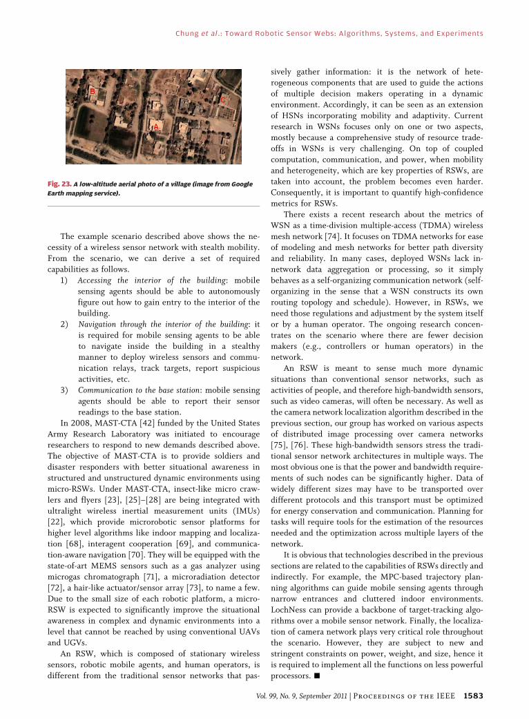
interest. For example, consider the village shown in
Fig. 23. Suppose that a series of aerial surveillance
photographs can be used to narrow down the targets to
three buildings (marked A, B, and C), but the data are too
coarse to choose one final target. It is a high-risk mission tosend squads to all three buildings, since 1) they are
spatially distributed and it makes the mission more
difficult and dangerous, and 2) there is a possibility that
one or more of these buildings may be trapsVfull of
improvised explosive devices. It is risky to send a team of
scouts or conventional remote-controlled ground robots,
since all the insurgents in the building will relocate
immediately once they detect scout activity. The missionobjective is to discern the contents of these buildings and
report it to the friendly force in the green zone.
TABLE 5 MPC-Based Guidance Using the External Active-Set Strategy
With SNOPTTABLE 4 MPC-Based Guidance Using the Native SNOPT
Fig. 22. Trajectories generated by Algorithm IV.2. The desired circular trajectory is in blue-dashed line, and no-flight zones in red-dashed line. The
initial positions are marked as ‘‘o’’ and the blue-dashed straight lines in the beginning of trajectories denote the initial reference trajectories.
Chung et al. : Toward Robotic Sensor Webs: Algorithms, Systems, and Experiments
1582 Proceedings of the IEEE | Vol. 99, No. 9, September 2011
The example scenario described above shows the ne-
cessity of a wireless sensor network with stealth mobility.
From the scenario, we can derive a set of requiredcapabilities as follows.
1) Accessing the interior of the building: mobile
sensing agents should be able to autonomously
figure out how to gain entry to the interior of the
building.
2) Navigation through the interior of the building: it
is required for mobile sensing agents to be able
to navigate inside the building in a stealthymanner to deploy wireless sensors and commu-
nication relays, track targets, report suspicious
activities, etc.
3) Communication to the base station: mobile sensing
agents should be able to report their sensor
readings to the base station.
In 2008, MAST-CTA [42] funded by the United States
Army Research Laboratory was initiated to encourageresearchers to respond to new demands described above.
The objective of MAST-CTA is to provide soldiers and
disaster responders with better situational awareness in
structured and unstructured dynamic environments using
micro-RSWs. Under MAST-CTA, insect-like micro craw-
lers and flyers [23], [25]–[28] are being integrated with
ultralight wireless inertial measurement units (IMUs)
[22], which provide microrobotic sensor platforms forhigher level algorithms like indoor mapping and localiza-
tion [68], interagent cooperation [69], and communica-
tion-aware navigation [70]. They will be equipped with the
state-of-art MEMS sensors such as a gas analyzer using
microgas chromatograph [71], a microradiation detector
[72], a hair-like actuator/sensor array [73], to name a few.
Due to the small size of each robotic platform, a micro-
RSW is expected to significantly improve the situationalawareness in complex and dynamic environments into a
level that cannot be reached by using conventional UAVs
and UGVs.
An RSW, which is composed of stationary wireless
sensors, robotic mobile agents, and human operators, is
different from the traditional sensor networks that pas-
sively gather information: it is the network of hete-rogeneous components that are used to guide the actions
of multiple decision makers operating in a dynamic
environment. Accordingly, it can be seen as an extension
of HSNs incorporating mobility and adaptivity. Current
research in WSNs focuses only on one or two aspects,
mostly because a comprehensive study of resource trade-
offs in WSNs is very challenging. On top of coupled
computation, communication, and power, when mobilityand heterogeneity, which are key properties of RSWs, are
taken into account, the problem becomes even harder.
Consequently, it is important to quantify high-confidence
metrics for RSWs.
There exists a recent research about the metrics of
WSN as a time-division multiple-access (TDMA) wireless
mesh network [74]. It focuses on TDMA networks for ease
of modeling and mesh networks for better path diversityand reliability. In many cases, deployed WSNs lack in-
network data aggregation or processing, so it simply
behaves as a self-organizing communication network (self-
organizing in the sense that a WSN constructs its own
routing topology and schedule). However, in RSWs, we
need those regulations and adjustment by the system itself
or by a human operator. The ongoing research concen-
trates on the scenario where there are fewer decisionmakers (e.g., controllers or human operators) in the
network.
An RSW is meant to sense much more dynamic
situations than conventional sensor networks, such as
activities of people, and therefore high-bandwidth sensors,
such as video cameras, will often be necessary. As well as
the camera network localization algorithm described in the
previous section, our group has worked on various aspectsof distributed image processing over camera networks
[75], [76]. These high-bandwidth sensors stress the tradi-
tional sensor network architectures in multiple ways. The
most obvious one is that the power and bandwidth require-
ments of such nodes can be significantly higher. Data of
widely different sizes may have to be transported over
different protocols and this transport must be optimized
for energy conservation and communication. Planning fortasks will require tools for the estimation of the resources
needed and the optimization across multiple layers of the
network.
It is obvious that technologies described in the previous
sections are related to the capabilities of RSWs directly and
indirectly. For example, the MPC-based trajectory plan-
ning algorithms can guide mobile sensing agents through
narrow entrances and cluttered indoor environments.LochNess can provide a backbone of target-tracking algo-
rithms over a mobile sensor network. Finally, the localiza-
tion of camera network plays very critical role throughout
the scenario. However, they are subject to new and
stringent constraints on power, weight, and size, hence it
is required to implement all the functions on less powerful
processors. h
Fig. 23. A low-altitude aerial photo of a village (image from Google
Earth mapping service).
Chung et al. : Toward Robotic Sensor Webs: Algorithms, Systems, and Experiments
Vol. 99, No. 9, September 2011 | Proceedings of the IEEE 1583

REF ERENCE S
[1] C. Tomlin, G. J. Pappas, and S. Sastry,BConflict resolution for air trafficmanagement: A study in multi-agent hybridsystems,[ IEEE Trans. Autom. Control, vol. 43,no. 4, pp. 509–521, Apr. 1998.
[2] R. Fierro, A. Das, J. Spletzer, J. Esposito,V. Kumar, J. Ostrowski, G. Pappas, C. Taylor,Y. Hur, R. Alur, I. Lee, G. Grudic, andB. Southall, BA framework and architecturefor multirobot coordination,[ Int. J. Robot.Res., vol. 21, pp. 977–995, 2002.
[3] P. Stone and M. Veloso, BMultiagent systems:A survey from a machine learningperspective,[ Autonom. Robots, vol. 8,no. 3, pp. 345–383, 2000.
[4] M. A. Hsieh, A. Cowley, J. F. Keller,L. Chaimowicz, B. Grocholsky, V. Kumar,C. J. Talyor, Y. Endo, R. Arkin, B. Jung,D. Wolf, G. Sukhatme, and D. C. MacKenzie,BAdaptive teams of autonomous aerial andground robots for situational awareness,[J. Field Robot., vol. 24, pp. 991–1014, 2007.
[5] M. Schwager, D. Rus, and J. J. Slotine,BDecentralized, adaptive coverage control fornetworked robot,[ Int. J. Robot. Res., vol. 28,no. 3, pp. 357–375, 2009.
[6] D. Estrin, D. Culler, K. Pister, andG. Sukhatme, BConnecting the physicalworld with pervasive networks,[ IEEEPervasive Comput., vol. 1, no. 1, pp. 59–69,Jan. 2002.
[7] I. Akyidliz, W. Su, Y. Sankarasubramaniam,and E. Cayirci, BA survey on sensornetworks,[ IEEE Commun. Mag., vol. 40,no. 8, pp. 102–116, Aug. 2002.
[8] H. Gharavi and S. P. Kumar, Eds., BSensornetworks and applications,[ Proc. IEEE,vol. 91, no. 8, Aug. 2003, special issue.
[9] W. S. Jang and W. M. Healy, BWireless sensornetwork performance metrics for buildingapplications,[ Energy Buildings, vol. 42, no. 6,pp. 862–868, 2010.
[10] J. J. Evans, J. F. Janek, A. Gum, andB. L. Hunter, BWireless sensor networkdesign for flexible environmentalmonitoring,[ J. Eng. Technol., vol. 25, no. 1,pp. 46–52, 2008.
[11] K. M. Yousef, J. N. Al-Karaki, andA. M. Shatnawi, BIntelligent traffic lightflow control system using wirelesssensors networks,[ J. Inf. Sci. Eng., vol. 26,no. 3, pp. 753–768, 2010.
[12] F. Franceschini, M. Galetto, D. Maisano, andL. Mastrogiacomo, BA review of localizationalgorithms for distributed wireless sensornetworks in manufacturing,[ Int. J. Comput.Integr. Manuf., vol. 22, no. 7, pp. 698–716,2009.
[13] C. Hsiao, R. Lee, I. Chou, C. Lin, andD. Huang, BA tele-emergent system forlong-term ECG monitoring over wirelesssensor network,[ Biomed. Eng.VAppl. BasisCommun., vol. 19, no. 3, pp. 187–197, 2007.
[14] H. Yang and S.-H. Yang, BIndoor localizationsystems-tracking objects and personnel withsensors, wireless networks and RFID,[ Meas.Control, vol. 42, no. 1, pp. 18–23, 2009.
[15] X. Wang, S. Wang, and D. Bi, BDistributedvisual-target-surveillance system inwireless sensor networks,[ IEEE Trans.Syst. Man Cybern. B, Cybern., vol. 39, no. 5,pp. 1134–1146, Oct. 2009.
[16] P. Dutta, J. Hui, J. Jeong, S. Kim, C. Sharp,J. Taneja, G. Tolle, K. Whitehouse, andD. Culler, BTrio: Enabling sustainable andscalable outdoor wireless sensor networkdeployments,[ in Proc. Int. Conf. Inf. Process.Sensor Netw., Special Track on Platform Tools
and Design Methods for Network EmbeddedSensors, 2006, DOI: 10.1145/1127777.1127839.
[17] G. Werner-Allen, P. Swieskowski, andM. Welsh, Motelab: A wireless sensor networktestbed, Los Angeles, CA, 2005, pp. 483–488.
[18] K. Sohrabi, J. Gao, V. Ailawadhi, andG. J. Pottie, BProtocols for self-organization ofa wireless sensor network,[ IEEE PersonalCommun., vol. 7, no. 5, pp. 16–27, Oct. 2000.
[19] Y. Lin, B. Chen, and P. K. Varshney,BDecision fusion rules in multi-hopwireless sensor networks,[ IEEETrans. Aerosp. Electron. Syst., vol. 41, no. 2,pp. 475–488, Apr. 2005.
[20] A. Rahimi, B. Dunagan, and T. Darrell,BSimultaneous calibration and tracking witha network of non-overlapping sensors,[ inProc. Comput. Vis. Pattern Recognit., vol. 1,Jul. 2004, pp. 187–194.
[21] K. S. Pister and L. Doherty, BTSMP: Timesynchronized mesh protocol,[ in Proc. IASTEDInt. Symp. Distrib. Sensor Netw., Orlando, FL,2008, pp. 391–398.
[22] A. Mehta and K. Pister, BWARPWING: Acomplete open source control platform forminiature robots,[ in Proc. IEEE/RSJ Int. Conf.Intell. Robots Syst., 2010, pp. 5169–5174.
[23] P. Birkmeyer, K. Peterson, and R. Fearing,BDash: A dynamic 15 g hexapedal robot,[ inProc. IEEE Int. Conf. Intell. Robots Syst., 2009,pp. 2683–2689.
[24] A. Hoover, S. Burden, X.-Y. Fu, S. Sastry, andR. S. Fearing, BBio-inspired design anddynamic maneuverability of a minimallyactuated six-legged robot,[ in Proc. IEEEInt. Conf. Biomed. Robot. Biomech., 2010,pp. 869–876.
[25] A. Hoover and R. Fearing, BAnalysis ofoff-axis performance of compliantmechanisms with applications to mobilemillirobots,[ in Proc. IEEE Int. Conf. Intell.Robots Syst., 2009, pp. 2770–2776.
[26] J. Humbert, I. Chopra, R. Fearing, R. J. Full,R. J. Wood, and M. Dickinson, BDevelopmentof micromechanics for micro-autonomoussystems (ARL-MAST CTA program),[ in Proc.SPIE, 2009, vol. 7318, DOI:10.1117/12.820881.
[27] C. Li, A. M. Hoover, P. Birkmeyer,P. Umbanhowar, R. Fearing, and D. Goldman,BSystematic study of the performance of smallrobots on controlled laboratory substrates,[ inProc. SPIE Defense Security Sens. Conf., 2010,DOI: 10.1117/12.851047.
[28] E. R. Ulrich, D. J. Pines, and J. S. Humbert,BFrom falling to flying: The path to poweredflight of a robotic samara nano air vehicle,[Bioinspirat. Biomimetics, vol. 5, no. 4, 2010,DOI: 10.1088/1748-3182/5/4/045009.
[29] D. H. Shim, H. J. Kim, and S. Sastry,BHierarchical control system synthesis forrotorcraft-based unmanned aerial vehicles,[in Proc. AIAA Guid. Navig. Control Conf., 2000,AIAA-2000-4057.
[30] D. H. Shim, BHierarchical flight controlsystem synthesis for rotorcraft-basedunmanned aerial vehicles,[ Ph.D.dissertation, Dept. Mech. Eng., Univ.California Berkeley, CA, 2000.
[31] R. Vidal, O. Shakernia, H. J. Kim, H. Shim,and S. Sastry, BMulti-agent probabilisticpursuit-evasion games with unmannedground and aerial vehicles,[ IEEE Trans.Robot. Autom., vol. 18, no. 5, pp. 662–669,Oct. 2002.
[32] D. H. Shim, H. J. Kim, H. Chung, andS. Sastry, BMulti-functional autopilotdesign and experiments for rotorcraft-based
unmanned aerial vehicles,[ in Proc. 20thDigit. Avionics Syst. Conf., 2001, vol. 1,pp. 3C4/1–3C4/8.
[33] E. Shaw, H. Chung, S. Sastry, and J. K. Hedrick,BUnmanned helicopter formation flightexperiment for the study of mesh stability,[ inCooperative Systems: Control and Optimization,vol. 588, Lecture Notes in Economics andMathematical Systems, D. Grundel,R. Murphey, P. Pardalos, and O. Prokopyev,Eds. Berlin, Germany: Springer-Verlag, 2007.
[34] H. J. Kim, D. H. Shim, and S. Sastry, BFlyingrobots: Modeling, control, and decisionmaking,[ Proc. IEEE Int. Conf. Robot. Autom.,2002, vol. 1, pp. 66–71.
[35] D. H. Shim, H. Chung, and S. Sastry,BConflict-free navigation in unknown urbanenvironments,[ IEEE Robot. Autom. Soc. Mag.,vol. 13, no. 3, pp. 27–33, Sep. 2006.
[36] D. H. Shim, H. J. Kim, and S. Sastry,BDecentralized nonlinear model predictivecontrol of multiple flying robots in dynamicenvironments,[ in Proc. IEEE Conf. DecisionControl, 2003, vol. 4, pp. 3621–3626.
[37] H. J. Kim and D. H. Shim, BA flight controlsystem for aerial robots: Algorithms andexperiments,[ IFAC Control Eng. Practice,vol. 11, no. 12, pp. 1389–1400, 2003.
[38] H. Chung, E. Polak, and S. S. Sastry, BAnexternal active-set strategy for solvingoptimal control problems,[ IEEE Trans.Autom. Control, vol. 54, no. 5, pp. 1129–1133,May 2009.
[39] B. Sinopoli, C. Sharp, L. Schenato,S. Schaffert, and S. Sastry, BDistributedcontrol applications within sensor networks,[Proc. IEEE, vol. 91, no. 8, pp. 1235–1246,Aug. 2003.
[40] B. Sinopoli, L. Schenato, M. Franceschetti,K. Poolla, M. I. Jordan, and S. S. Sastry,BKalman filtering with intermittentobservations,[ IEEE Trans. Autom. Control,vol. 49, no. 9, pp. 1453–1464, Sep. 2004.
[41] S. Oh, L. Schenato, P. Chen, and S. Sastry,BTracking and coordination of multipleagents using sensor networks: System design,algorithms and experiments,[ Proc. IEEE,vol. 95, no. 1, pp. 234–254, Jan. 2007.
[42] [Online]. Available: http://www.mast-cta-org
[43] J. Hill, M. Horton, R. Kling, andL. Krishnamurthy, BThe platforms enablingwireless sensor networks,[ Commun. ACM,vol. 47, no. 6, pp. 41–46, 2004.
[44] R. Burkard and R. Cela, BLinear assignmentproblem and extensions,[ Karl-FranzensUniv. Graz, Graz, Austria, Tech. Rep. 127,1998.
[45] S. Oh, S. Russell, and S. Sastry, BMarkovchain Monte Carlo data association formulti-target tracking,[ IEEE Trans. Autom.Control, vol. 54, no. 3, pp. 481–497,Mar. 2009.
[46] P. W.-C. Chen, P. Ahammad, C. Boyer,S.-I. Huang, L. Lin, E. J. Lobaton,M. L. Meingast, S. Oh, S. Wang, P. Yan,A. Yang, C. Yeo, L.-C. Chang, D. Tygar, andS. S. Sastry, BCITRIC: A low-bandwidthwireless camera network platform,[ in Proc.ACM/IEEE Int. Conf. Distrib. Smart Cameras,Stanford, CA, Sep. 2008, DOI: 10.1109/ICDSC.2008.4635675.
[47] W. Mantzel, C. Hyeokho, and R. Baraniuk,BDistributed camera network localization,[ inProc. Asilomar Conf. Signals Syst. Comput.,Nov. 2004, vol. 2, pp. 1381–1386.
[48] S. Funiak, C. Guestrin, M. Paskin, andR. Sukthankar, BDistributed localization ofnetworked cameras,[ in Proc. 5th Int. Conf. Inf.Process. Sensor Netw., Apr. 2006, pp. 34–42.
Chung et al. : Toward Robotic Sensor Webs: Algorithms, Systems, and Experiments
1584 Proceedings of the IEEE | Vol. 99, No. 9, September 2011

[49] R. Cucchiara, A. Prati, and R. Vezzani, BAsystem for automatic face obscuration forprivacy purposes,[ Pattern Recognit. Lett.,vol. 27, no. 15, Nov. 2006, DOI: 10.1016/j.patrec.2006.02.018.
[50] J. Black, T. Ellis, and P. Rosin, BMultiview image surveillance and tracking,[ inProc. Workshop Motion Video Comput., 2002,pp. 169–174.
[51] L. Lee, R. Romano, and G. Stein, BMonitoringactivities from multiple video streams:Establishing a common coordinate frame,[IEEE Trans. Pattern Anal. Mach. Intell.,vol. 22, no. 8, pp. 758–767, Aug. 2000.
[52] M. Meingast, S. Oh, and S. Sastry, BAutomaticcamera network localization using objectimage tracks,[ in Proc. IEEE Int. Conf. Comput.Vis., Rio de Janeiro, Brazil, Oct. 2007,DOI: 10.1109/ICCV.2007.4409214.
[53] M. Maroti, B. Kusy, G. Balogh, P. Volgyesi,A. Nadas, K. Molnar, S. Dora, and A. Ledeczi,BRadio interferometric geolocation,[ in Proc.ACM SenSys, Nov. 2005, DOI: 10.1145/1098918.1098920.
[54] M. Meingast, M. Kushwaha, S. Oh,X. Koutsoukos, A. Ledeczi, andS. Sastry, BFusion-based localizationfor a heterogeneous camera network,[ inProc. ACM/IEEE Int. Conf. Distrib. SmartCameras, Stanford, CA, Sep. 2008,DOI: 10.1109/ICDSC.2008.4635718.
[55] Y. Ma, S. Soatto, J. Kosecka, and S. Sastry,An Invitation to 3-D Vision: From Imagesto Geometric Models, ser. InterdisciplinaryApplied Mathematics. New York:Springer-Verlag, Nov. 2003.
[56] EasyCal Calibration Toolbox. [Online].Available: http://www.cis.upenn.edu/~kostas/tele-immersion/research/downloads/EasyCal/
[57] P. Dutta, M. Grimmer, A. Arora, S. Bibyk, andD. Culler, BDesign of a wireless sensornetwork platform for detecting rare, random,and ephemeral events,[ in Proc. 4th Int.Conf. Inf. Process. Sensor Netw., Special Trackon Platform Tools and Design Methods for
Network Embedded Sensors, Apr. 2005,pp. 497–502.
[58] Y. K. Hwang and N. Ahuja, BGross motionplanning-a survey,[ ACM Comput. Surv.,vol. 24, no. 3, pp. 220–291, 1992.
[59] G. J. Sutton and R. R. Bitmead, BPerformanceand computational implementation ofnonlinear model predictive control on asubmarine,[ in Nonlinear Model PredictiveControl, vol. 26, F. Allgoower andA. Zheng, Eds. New York: Birkhauser,2000, vol. 26, pp. 461–471.
[60] D. H. Shim and S. Sastry, BA situation-awareflight control system design using real-timemodel predictive control for unmannedautonomous helicopters,[ in AIAA Guid.Navig. Control Conf., 2006, AIAA-2006-6101.
[61] K. Holmstrom, A. O. Goran, andM. M. Edvall, User’s Guide for TOMLAB,Tomlab Optimization Inc., Dec. 2006.
[62] W. Murray, P. E. Gill, and M. A. Saunders,BSNOPT: An SQP algorithm for large-scaleconstrained optimization,[ SIAM J. Optim.,vol. 12, pp. 979–1006, 2002.
[63] P. E. Gill, W. Murray, M. A. Saunders, andM. H. Wright, BUser’s guide for NPSOL 5.0: Afortran package for nonlinear programming,[Syst. Optim. Lab., Dept. Operat. Res.,Stanford Univ., Stanford, CA, Tech. Rep. SOL86-2, 1998.
[64] K. Schittkowski, BOn the convergence of asequential quadratic programming methodwith an augmented Lagrangian line searchfunction,[ Syst. Optim. Lab., Stanford Univ.,Stanford, CA, Tech. Rep., 1982.
[65] E. Polak, Optimization: Algorithms andConsistent Approximations, ser. AppliedMathematical Sciences. New York:Springer-Verlag, 1997, vol. 124.
[66] I. M. Mitchell, A. M. Bayen, and C. J. Tomlin,BA time-dependent Hamilton-Jacobiformulation of reachable sets for continuousdynamic games,[ IEEE Trans. Autom. Control,vol. 50, no. 7, pp. 947–957, Jul. 2005.
[67] Y. Kang and J. K. Hedrick, BLinear trackingfor a fixed-wing UAV using nonlinear model
predictive control,[ IEEE Trans. Control Syst.Technol., vol. 17, no. 5, pp. 1202–1210,Sep. 2009.
[68] R. He, A. Bachrach, M. Achtelik,A. Geramifard, D. Gurdan, S. Prentice,J. Stumpf, and N. Roy, BOn the design and useof a micro air vehicle to track and avoidadversaries,[ Int. J. Robot. Res., vol. 29, no. 5,pp. 529–546, 2010.
[69] N. Michael, J. Fink, and V. Kumar,BCooperative manipulation andtransportation with aerial robots,[ Autonom.Robots, vol. 30, no. 1, pp. 73–86, Jan. 2011.
[70] Y. Mostofi, BDecentralizedcommunication-aware motion planning inmobile networks: An information-gainapproach,[ J. Intell. Robot. Syst.,vol. 56, pp. 233–256, 2009.
[71] S.-J. Kim, S. Reidy, B. Block, K. Wise,E. Zellers, and K. Kurabayashi, BA low power,high-speed miniaturized thermal modulatorfor comprehensive 2D gas chromatography,’’in Proc. IEEE Int. Conf. Microelectromech. Syst.,Piscataway, NJ, 2010, pp. 124–127.
[72] C. K. Eun and Y. B. Gianchandani, BAmicrofabricated steel and glass radiationdetector with inherent wireless signaling,[J. Micromech. Microeng., vol. 21, 015003, 2011.
[73] M. Sadeghi, H. Kim, and K. Najafi,BElectrostatically driven micro-hydraulicactuator arrays,[ in Proc. IEEE Int. Conf.Microelectromech. Syst., 2010, pp. 15–18.
[74] P. W. Chen, BWireless sensor network metricsfor real-time systems,[ Ph.D. dissertation,Electr. Eng. Comput. Sci. Dept., Univ.California Berkeley, Berkeley, CA, May 2009.
[75] A. Yang, S. Maji, K. Hong, P. Yan, andS. Sastry, BDistributed compression andfusion of nonnegative sparse signals formultiple-view object recognition,[ in Proc.Int. Conf. Inf. Fusion, 2009, pp. 1867–1874.
[76] A. Yang, J. Wright, S. Sastry, and Y. Ma,BUnsupervised segmentation of naturalimages via lossy data compression,[Comput. Vis. Image Understand.,vol. 110, no. 2, pp. 212–225, 2008.
ABOUT T HE AUTHO RS
Hoam Chung (Member, IEEE) received the B.A.
and M.S. degrees in precision mechanical engi-
neering from Hanyang University, Seoul, Korea, in
1997 and 1999, respectively, and the Ph.D. degree
in mechanical engineering from the University of
California Berkeley, Berkeley, in May 2006.
He has worked in the Intelligent Machines and
Robotics Laboratory at the University of California
Berkeley as a Postdoctoral Researcher and a
Research Scientist from 2006 to 2009. He has
led Autonomous Systems Group in the lab from 2007 to 2009, and has
participated in various projects including ARO MURI SWARMS and
MAST-CTA. He joined the Faculty of Engineering at Monash University,
Clayton, Vic., Australia, in 2010, and is now a Lecturer in the Department
of Mechanical and Aerospace Engineering. His research interests include
receding horizon control (RHC) theory and application, autonomous
miniature flyers, semi-infinite optimization problems, real-time system
design and implementation, and autonomous unmanned systems
[unmanned aerial vehicles (UAVs), unmanned ground vehicles (UGVs),
and unmanned undersea vehicles (UUVs)].
Songhwai Oh (Member, IEEE) received the B.S.
(with highest honors), M.S., and Ph.D. degrees in
electrical engineering and computer sciences from
the University of California Berkeley, Berkeley, in
1995, 2003, and 2006, respectively.
Currently, he is an Assistant Professor in the
School of Electrical Engineering and Computer
Science, Seoul National University, Seoul, Korea.
His research interests include cyber-physical
systems, wireless sensor networks, robotics, esti-
mation and control of stochastic systems, multimodal sensor fusion, and
machine learning. Before his Ph.D. studies, he worked as a Senior
Software Engineer at Synopsys, Inc. and a Microprocessor Design
Engineer at Intel Corporation. In 2007, he was a Postdoctoral Researcher
at the Electrical Engineering and Computer Sciences Department,
University of California Berkeley, Berkeley. From 2007 to 2009, he was
an Assistant Professor of Electrical Engineering and Computer Science in
the School of Engineering, University of California Merced, Merced.
Chung et al. : Toward Robotic Sensor Webs: Algorithms, Systems, and Experiments
Vol. 99, No. 9, September 2011 | Proceedings of the IEEE 1585
David Hyunchul Shim (Member, IEEE) received
the B.S. and M.S. degrees in mechanical design and
production engineering from Seoul National Uni-
versity, Seoul, Korea, in 1991 and 1993, respec-
tively, and the Ph.D. degree in mechanical
engineering from the University of California
Berkeley, Berkeley, in 2000.
From 1993 to 1994, he was with Hyundai Motor
Company, Korea, as Transmission Design Engi-
neer. From 2001 to 2005, he was with Maxtor
Corporation, Milpitas, CA as Staff Servo Engineer specialized in advanced
servo control systems for hard disk drives. From 2005 to 2007, he was
with the University of California Berkeley as Principal Engineer, in charge
of Berkeley Aerobot Team, working on advanced unmanned aerial
vehicles (UAVs) programs such as DARPA SEC and UCAR. In 2007, he
joined the Department of Aerospace Engineering, Korea Advanced
Institute of Science and Technology (KAIST), Daejon, Korea, as an
Assistant Professor. He is now an Associate Professor working on various
research projects on UAVs in the area of flight dynamics and control,
multiagent coordination, and unmanned ground systems.
S. Shankar Sastry (Fellow, IEEE) received the
Ph.D. degree in electrical engineering and com-
puter science from the University of California
Berkeley, Berkeley, in 1981.
He is currently the Dean of the College of
Engineering. He was the Chairman, Department of
Electrical Engineering and Computer Sciences,
University of California Berkeley, from 2001 to
July 2004. Until August 2007, he was the Director
of the Center for Information Technology Re-
search in the Interest of Society (CITRIS), University of California
Berkeley. He served as Director of the Information Technology Office at
DARPA from 1999 to 2001. From 1996 to 1999, he was the Director of the
Electronics Research Laboratory at Berkeley, an organized research unit
on the Berkeley campus conducting research in computer sciences and
all aspects of electrical engineering. He has supervised over 50 doctoral
students to completion and over 50 M.S. students. His students now
occupy leadership roles in several locations such as Dean of Engineering
at the California Institute of Technology (Caltech), Pasadena, Director of
Information Systems Laboratory, Stanford University, Stanford, CA, Army
Research Office, and on the faculties of every major university in the
United States and abroad.
Dr. Sastry is the NEC Distinguished Professor of EECS, Bioengineering,
and Mechanical Engineering. He was elected into the National Academy
of Engineering in 2001 Bfor pioneering contributions to the design of
hybrid and embedded systems.[ He was also elected to the American
Academy of Arts and Sciences in 2004. He received the President of India
Gold Medal in 1977, the IBM Faculty Development award for 1983–1985,
the National Science Foundation (NSF) Presidential Young Investigator
Award in 1985, and the Eckman Award of the of the American Automatic
Control Council in 1990, an M.A. (honoris causa) from Harvard University
in 1994, the distinguished Alumnus Award of the Indian Institute of
Technology in 1999, and the David Marr prize for the best paper at the
International Conference in Computer Vision in 1999 and the Ragazzini
Award of the American Control Council in 2005.
Chung et al. : Toward Robotic Sensor Webs: Algorithms, Systems, and Experiments
1586 Proceedings of the IEEE | Vol. 99, No. 9, September 2011