invited paper opticaltechniquesfor informationsecurity
TRANSCRIPT
INV ITEDP A P E R
Optical Techniques forInformation SecurityEncryption of information, taking advantage of the many degrees of freedom
available in optical waveforms, can be used to safely transmit, protect, store and
authenticate data.
By Osamu Matoba, Member IEEE, Takanori Nomura, Elisabet Perez-Cabre,
Marıa S. Millan, and Bahram Javidi, Fellow IEEE
ABSTRACT | This paper presents an overview of the potential
of free space optical technology in information security,
encryption, and authentication. Optical waveform posses
many degrees of freedom such as amplitude, phase, polariza-
tion, spectral content, and multiplexing which can be combined
in different ways to make the information encoding more
secure. This paper reviews optical techniques for encryption
and security of two-dimensional and three-dimensional data.
Interferometric methods are used to record and retrieve data
by either optical or digital holography for security applications.
Digital holograms are widely used in recording and processing
three dimensional data, and are attractive for securing three
dimensional data. Also, we review optical authentication
techniques applied to ID tags with visible and near infrared
imaging. A variety of images and signatures, including biomet-
rics, random codes, and primary images can be combined in an
optical ID tag for security and authentication.
KEYWORDS | Authentication; digital holography; ID tag; infor-
mation security; optical encryption; phase modulation
I . INTRODUCTION
Information security is an important concern in many
societies. There have been many studies on data encryp-
tion, authentication, and watermarking. In digital form,
digital signature is used to protect and to give access to the
original data. Optical security and encryption have
attracted the interest of many researchers. Optics provides
many degrees of freedom to handle parameters such asamplitude, phase, wavelength, and polarization [1]–[3].
Optical waves can additionally be combined in multi-
plexed distributions. For instance, holographic patches in
CD, DVD, and cash notes allow us to easily see colored
images with different viewing angles. Biometrics, finger-
print, iris, and retina imaged by using infrared or visible
light have already been used for secure identification.
Recently, the quantum nature of light has also been usedto provide a security key code in quantum communication
ways [4].
In this paper, we review free space optical techniques
for information encryption and security. These approaches
are based on manipulating some physical parameters of the
optical waves that convey the information. In this context,
the double random phase encryption method [5] opened
new fields of research in analog optical informationprocessing. In this encryption method, original data
embedded in two-dimensional amplitude information are
transformed into a white-noise-like image by two random
phase masks located in the input and the Fourier planes.
Many variations of this approach have been introduced
including employing the phase mask in the Fresnel domain
where the unknown location of the key presents additional
difficulties to the attacker. This architecture is effective torealize optical implementations by using modern spatial
light modulators (e.g., Liquid crystal displays) and digital
image sensors (e.g., CCD or CMOS). By properly utilizing
some physical properties of optical waves such as
polarization, wavelength, and three-dimensional positions
of random phase masks in Fresnel or Fourier domain,
security levels in an optical encryption system can be
Manuscript received July 13, 2008; revised November 30, 2008.
Current version published May 13, 2009. To the financial support of
Spanish Ministerio de Educacion y Ciencia and FEDER (project DPI2006-05479).
O. Matoba is with the Department of Computer Science and Systems Engineering,
Kobe University, Kobe 657-8501, Japan (e-mail: [email protected]).
T. Nomura is with the Department of Opto-Mechatronics, Wakayama University,
930 Sakaedani, Wakayama 640-8510, Japan (e-mail: [email protected]).
E. Perez-Cabre and M. S. Millan are with the Optics and Optometry Department,
Universitat Politecnica de Catalunya, Violinista Vellsola 37 08222 Terrassa-Spain
(e-mail: [email protected]; [email protected]).
B. Javidi is with the Department of Electrical and Computer Engineering, University of
Connecticut, Storrs, CT 06269-2157 USA (e-mail: [email protected]).
Digital Object Identifier: 10.1109/JPROC.2009.2018367
1128 Proceedings of the IEEE | Vol. 97, No. 6, June 2009 0018-9219/$25.00 �2009 IEEE
Authorized licensed use limited to: UNIVERSITY OF CONNECTICUT. Downloaded on May 27, 2009 at 13:26 from IEEE Xplore. Restrictions apply.

increased [6]–[15]. The storage of optically encrypted datacan be implemented optical or digitally. The digital format
of encrypted data facilitates the use of encryption
techniques in computers and digital data communication.
The encrypted data can be obtained in either a real or a
virtual optical system simulated by computer.
Optics provides useful resources for remote, real-time,
automatic, and reliable signal verification [16]–[29]. This
paper overviews optical identification (ID) tags for robust,real-time and remote identification to enable surveillance
or tracking of moving objects, such as vehicles. Different
categories of identifying signals or factors are combined to
produce positive verification for an authentic object.
Designs for distortion-invariant ID tags are presented to
allow remote information readout under the effects of
scale variations or/and in-plane rotations.
The paper is organized as following. In Section II, wepresent optical encryption methods based on random
phase modulation in input plane, Fourier plane, and
Fresnel domain. Double random phase encryption tech-
nique is an attractive method for securing data. It is
intended to be implemented with fully random codes
which can be updated frequently. However, when the
codes are not random (that is fixed codes that are not
updated), this method is vulnerable to attacks. Therefore,more degrees of freedom of the optical wave have been
introduced to achieve a higher level of security with fixed
keys. Some of these approaches are presented which utilize
random phase modulation using physical properties of
optical wave such as polarization, wavelengths multi-
plexing, and Fresnel domain encoding. Encrypted data can
be stored in optical or digital form. In Section III,
encrypted data is stored using a volume holographicmemory. Various experimental results are provided to
show the feasibility of the secure optical data storage. In
Section IV, the combination of optical encryption and
digital holography is reviewed. The digital holographic
realization of random phase modulation in the Fourier or
Fresnel domain is presented. In the last two sections,
security applications based on optical encryption are
reviewed. Section V deals with polarization-based opticalencoding for authentication. Section VI introduces optical
ID tags for authentication of remote objects. This section
analyzes the robustness of ID tags against degradation,
scale, and rotation distortions in both simulated and
experimental results. Summary and conclusion are pre-
sented in Section VII.
II . OPTICAL ENCRYPTION METHODSBY RANDOM PHASE MODULATION
Optics can provide a higher level of security because many
degrees of freedom are available for manipulating infor-
mation [6]–[15]. In coherent linear systems, phase
modulation can easily transform the original amplitude
distribution into random distribution. The first demon-
stration of phase modulation and recovery of images usingholography and phase conjugation was presented by
Kogelnik [6]. In this system [6], the original image is
modulated by ground glass and then is recorded as a
hologram on film. In the retrieval process, phase conjugate
reconstruction is used. The phase modulation creates phase
distortion. The phase conjugation can cancel those
distortions and the original object is reconstructed
successfully. However, this method will not provide anyquantitative evaluation of security level.
In [1], optical amplitude and phase modulation in the
input plane were employed for the purpose of security
verification and authentication of objects. However, this
method did not provide encryption of data. To improve
the method, Refregier and Javidi proposed double random
phase encryption [5]. After the publication of this paper,
many optical encoding and decoding methods such asfully random phase encryption [7], Fresnel domain
random phase encryption [8], including spectral keys
for encryption [9], and polarization keys for encryption
[10]–[12] have been proposed. Various forms of optical
security techniques such as XOR encoding using polariza-
tion [15] or generation of random numbers based on
speckle patterns [30] have been presented by researchers.
In this section, we concentrate on overview of doublerandom phase encryption and its enhancement by using
keys in the Fresnel domain, and double random full phase
encryption [8].
A. Double Random Phase EncryptionFig. 1 shows an illustration of encryption and
decryption process of double random phase encryption
[5]. Here x and y denote the spatial domain coordinates,and � and � denote the Fourier domain coordinates. Let
fðx; yÞ denote the positive real-valued image to be
encrypted. Let nðx; yÞ and hð�; �Þ denote two independent
white sequences and are uniformly distributed on the
interval ½0; 2�� in the input and the Fourier plane. In the
encryption process, the input data is multiplied by a
random phase function �ðx; yÞ ¼ expf�inðx; yÞg in the
input plane. The Fourier transform of the modulated inputdata is multiplied by another random phase function,
Hð�; �Þ ¼ expf�ihð�; �Þg in the Fourier plane, and is
written by
Sð�; �Þ ¼ Fð�; �ÞHð�; �Þ (2.1)
where
Fð�; �Þ ¼ FT fðx; yÞ�ðx; yÞ½ �: (2.2)
In (2.2), FT½�� denotes the operation of Fourier
transform. This phase modulated data is inverse
Matoba et al.: Optical Techniques for Information Security
Vol. 97, No. 6, June 2009 | Proceedings of the IEEE 1129
Authorized licensed use limited to: UNIVERSITY OF CONNECTICUT. Downloaded on May 27, 2009 at 13:26 from IEEE Xplore. Restrictions apply.

Fourier-transformed and then encrypted data is obtained
as follows:
eðx; yÞ ¼ fðx; yÞ�ðx; yÞ½ � � FT�1 Hð�; �Þ½ � (2.3)
where � denotes convolution operation. These two phase
functions, �ðx; yÞ and Hð�; �Þ, can convert the original data
into a stationary-white-noise-like data. Here we note that the
random phase mask in the input plane prevents from the
attack using phase retrieval method. If there is no phase mask
in the input plane, one can know the Fourier spectra of theencrypted data and the priori information of real-valued
original image. By using phase retrieval method, one can
estimate the original real-valued data. The reader can see the
paper about the security characteristics in double random
phase encryption [31].
In the decryption process, two methods can be adopted
to recover the original data; one is to use a phase conjugate
mask of the random phase modulation used in the Fourierdomain in the encryption process and the other is to use a
phase conjugate readout of the encrypted data as shown in
Fig. 1(b) and (c), respectively.
At first, we describe a method to use a phase conjugate
mask of the random phase modulation used in the Fourier
plane in the encryption process. Here the key phase mask
used in the decryption process in the Fourier plane is denoted
by kð�; �Þ. In this case, the reconstructed data is given by
o1ðx; yÞ ¼ fðx; yÞ�ðx; yÞ½ � � Cðx; yÞ (2.4)
where
Cðx; yÞ ¼ FT�1 Hð�; �Þ½ � � FT Kð�; �Þ½ �: (2.5)
When one has a phase key, kð�; �Þ ¼ �hð�; �Þ, the original
data is successfully recovered because (2.5) becomes a delta
function. The random phase function in the input plane,
expf�inðx; yÞg, is removed by detecting an intensity-sensitive device. When one uses an incorrect phase key,
Fig. 1. Principle of double random phase encryption. (a) Encoding process and decoding processes by use of (b) phase conjugate of RPM2
and (c) phase conjugate of encrypted data.
Matoba et al. : Optical Techniques for Information Security
1130 Proceedings of the IEEE | Vol. 97, No. 6, June 2009
Authorized licensed use limited to: UNIVERSITY OF CONNECTICUT. Downloaded on May 27, 2009 at 13:26 from IEEE Xplore. Restrictions apply.

kð�; �Þ 6¼ �hð�; �Þ, the original data cannot be recoveredbecause (2.4) remains as white noise.
Next, we describe a method to use a phase conjugate of
the encrypted data. Note that the key phase mask used in
the decryption process in the Fourier plane is denoted by
kð�; �Þ. In this case, the reconstructed data is given by
o2ðx; yÞ ¼ f � ðx; yÞ� � ðx; yÞ½ � � Cðx; yÞ (2.6)
where
Cðx; yÞ ¼ FT�1 H � ð�; �Þ½ � � FT Kð�; �Þ½ �: (2.7)
When one has a phase key, kð�; �Þ ¼ hð�; �Þ, the original
data is successfully recovered because (2.7) becomes a delta
function and the random phase function in the input plane,
expfinðx; yÞg, is removed by detecting an intensity-
sensitive device. In this case, the same random phase
mask used in the encryption process can be used in the
decryption process. This is the advantage to implement.
This phase conjugate readout is used in secure holographicmemory system described in Section III. When one uses an
incorrect phase key, kð�; �Þ 6¼ hð�; �Þ, the original data
cannot be recovered because (2.6) remains as white noise.
We discuss the resistance of double phase encryption
technique against attacks. Optical encryption techniques
as described in [6]–[15] are not intended for strictly digital
implementation as there are many excellent mathematical
encryption algorithms for digital implementation. We notethat optical encryption techniques [6]–[15] are ideally
suited for optical domain applications, that is, when data is
in the optical domain such as optical data storage. Thus,
the codes are supposed to be random, that is, the codes can
be written on a spatial light modulator which can be
updated on a regular basis in real time. In this case, the
system is much more difficult to attack.
Strict digital implementation of conventional doublephase encryption technique with fixed codes may be
vulnerable against attacks. Several attacks have been reported
[32] against the conventional double random phase encryp-
tion technique with digital implementation, that is, one
single key in the input plane, one single key in the Fourier
domain, and using these stationary keys to encrypt all images
without updating the keys. These attacks are demonstrated by
computer simulation to illustrate the vulnerability of thealgorithm, although attacking a full optically implemented
system with updatable codes may be much more difficult.
The conventional double phase encryption is a linear
algorithm. Thus, it is vulnerable to these attacks. This
algorithm is shown to be resistant against brute force attacks
but it is vulnerable to chosen and known plaintext attacks.
Some of the attacks against the double random phase
encryption technique are impractical and others are effective.
An exhaustive search of the key is generally not practical.However, chosen and known plaintext attacks are able to
recover the keys. Secure modes for optical encryption can be
developed that overcome these attacks [33].
Given the risks presented by some attacks against
conventional double phase encryption by digital implemen-
tation, it is recommendable to use variations of the double
phase encoding technique. The most effective approach to
combat these attacks is to employ the encryption keys in theFresnel domain as described in the following subsection [8].
This would force the attacker to search for keys in a 3-D
volume which is very difficult. That correlation length of the
keys defines the search step size. That is, if encryption keys
with microns size correlation length are employed, then
microns size search steps may be required. The double phase
encryption by using the keys in the Fresnel domain would
provide an additional dimension to the keys which have to besearched by the attacker. Also, if possible, the encryption
keys should be updated so that we are not using the same
keys for different images, as in a one-time pad approach. In
general, the double phase encryption approach is useful in
the optical domain due to the bandwidth and speed of
computations, and the ability to update the codes fast. Thus,
optical domain applications with updating the keys may not
have a substantial computational cost. Key distribution,however, will also incur a cost, and carries its own risks of
being intercepted by an attacker.
B. Fresnel Domain Random Phase ModulationFurthermore, degree of freedom used in the encoding
can be increased by using three-dimensional positions of
the random phase masks in double random phase
encryption. The random phase masks can be located atFresnel domain as shown in Fig. 2. This technique is called
as Fresnel domain random phase modulation [8]. We
briefly present the Fresnel domain encryption method.
Two random phase masks are located as shown in Fig. 2.
Fresnel propagation with distance of z1 is described as
gðx; yÞ ¼ fðx; yÞ � hðx; y; z1Þ ¼ Prop fðx; yÞ½ �z1(2.8)
where hðx; y; z1Þ ¼ expð�ið�=�z1Þðx2 þ y2ÞÞ.The encrypted data is given by
eðx; yÞ ¼ FT�1 Prop Prop g1ð�; �ÞLð�; �Þ½ �f�z2Hð�; �Þ
h iz2
� �
(2.9)
where
g1ðx; yÞ ¼ Prop Prop fðx; yÞ½ �z1�ðx; yÞ
h if�z1
(2.10)
Matoba et al.: Optical Techniques for Information Security
Vol. 97, No. 6, June 2009 | Proceedings of the IEEE 1131
Authorized licensed use limited to: UNIVERSITY OF CONNECTICUT. Downloaded on May 27, 2009 at 13:26 from IEEE Xplore. Restrictions apply.

In this system, 3-D positions of the random phase masks
can be used as additional keys even when the random phase
masks are stolen. This makes the system more secure. We
note that there is the tradeoff between the improvements of
security and the mechanical precision and complexity of
the additional movable part required to use 3-D positions as
additional keycodes. We also note that for the sake ofsimplicity, we have not shown the possible lateral and
longitudinal location of the optical keys. In general, the
mathematical representations of the encryption process
could be written to include the ðx; y; zÞ location of the keys
in the Fresnel domain.
In other approaches to develop a multidimensional key,
wavelength-code with random phase modulation, fully
phase encryption, polarization encryption can be used.Fractional Fourier encryption is considered to be a part of
Fresnel domain random phase modulation because the
random phase masks can be located at any position in
Fresnel domain encryption.
III . SECURE DATA STORAGE USINGHOLOGRAPHIC MEMORY
Holographic data storage is one of promising candidates of
next generation optical disk memory to realize storage ca-
pacity of 1TB and data transfer speed of 1 Gbps [34]–[39].
In the holographic data storage, Fourier-transformed
pattern of two-dimensional binary data page is recorded
as a hologram in a thin medium. Therefore the phase
modulation technique to encode the data is suitable to
holographic memory systems because the waveform is
recorded as hologram [8]–[11], [40]–[50]. In the decryp-
tion process that is the reconstruction process, the phase
conjugate readout can be used. Fig. 3 shows an example ofsecure holographic memory systems using multidimen-
sional key. Random phase masks, their three-dimensional
positions, and wavelength can be used as multidimensional
keys to encode and decode the data. In another type of
encrypted holographic memories, the reference beam can
be phase-encoded [45]. The readout process using phase
masks is a key to access the data. In this section, we
describe secure holographic data storage systems based ondata encoding.
A. Secure Holographic Memory UsingAngular Multiplexing
One of the major holographic memories is based on
angular multiplexing. In the angular multiplexing, a bulk
material is used to record many numbers of holograms in
the same volume by changing the angle of plane referencewave. It is easy for phase conjugate reconstruction. Fig. 4
shows the experimental setup [42]. An Ar+ laser at a
wavelength of 514.5 nm was used as a coherent light source.
The light beam was divided into an object and a reference
Fig. 3. Schematics of secure holographic memory using multidimensional keys based on random phase masks,
their three-dimensional positions, and wavelength.
Fig. 2. Schematics of Fresnel domain random phase encryption.
Matoba et al. : Optical Techniques for Information Security
1132 Proceedings of the IEEE | Vol. 97, No. 6, June 2009
Authorized licensed use limited to: UNIVERSITY OF CONNECTICUT. Downloaded on May 27, 2009 at 13:26 from IEEE Xplore. Restrictions apply.
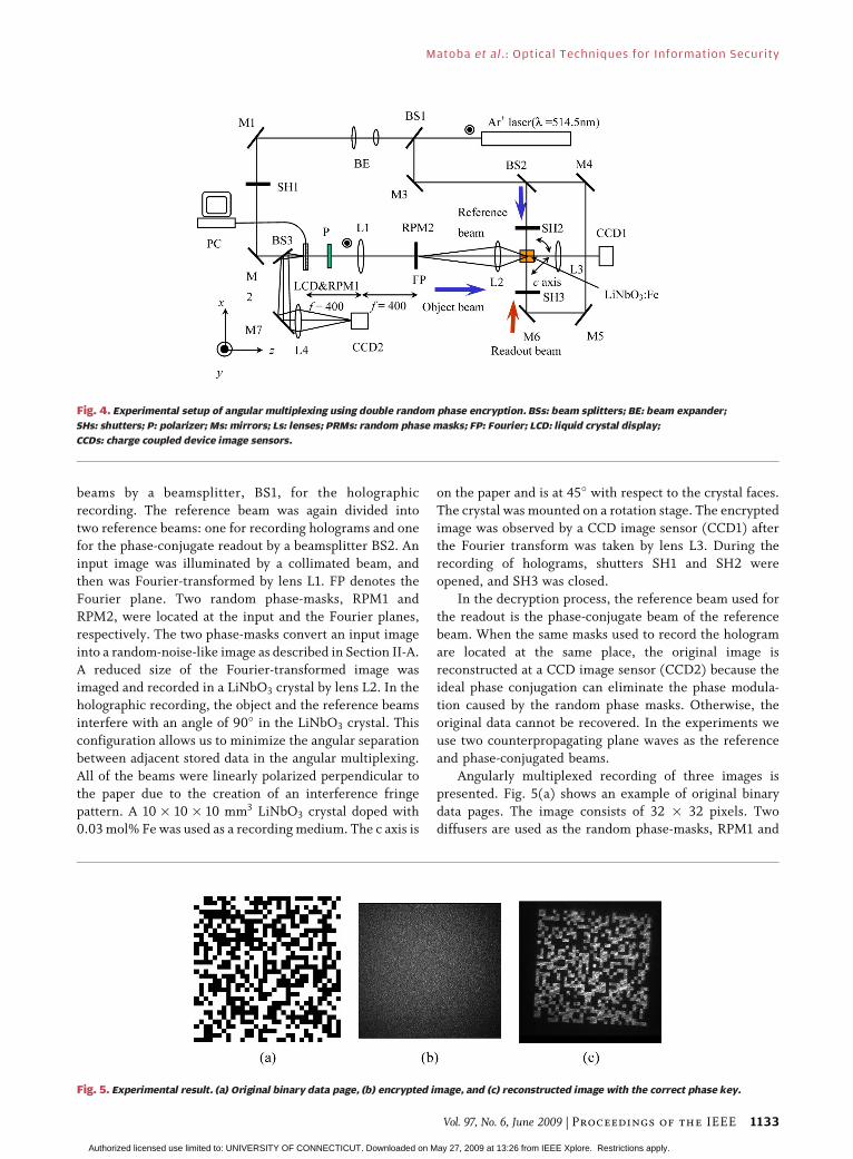
beams by a beamsplitter, BS1, for the holographic
recording. The reference beam was again divided into
two reference beams: one for recording holograms and onefor the phase-conjugate readout by a beamsplitter BS2. An
input image was illuminated by a collimated beam, and
then was Fourier-transformed by lens L1. FP denotes the
Fourier plane. Two random phase-masks, RPM1 and
RPM2, were located at the input and the Fourier planes,
respectively. The two phase-masks convert an input image
into a random-noise-like image as described in Section II-A.
A reduced size of the Fourier-transformed image wasimaged and recorded in a LiNbO3 crystal by lens L2. In the
holographic recording, the object and the reference beams
interfere with an angle of 90� in the LiNbO3 crystal. This
configuration allows us to minimize the angular separation
between adjacent stored data in the angular multiplexing.
All of the beams were linearly polarized perpendicular to
the paper due to the creation of an interference fringe
pattern. A 10� 10� 10 mm3 LiNbO3 crystal doped with0.03 mol% Fe was used as a recording medium. The c axis is
on the paper and is at 45� with respect to the crystal faces.
The crystal was mounted on a rotation stage. The encrypted
image was observed by a CCD image sensor (CCD1) afterthe Fourier transform was taken by lens L3. During the
recording of holograms, shutters SH1 and SH2 were
opened, and SH3 was closed.
In the decryption process, the reference beam used for
the readout is the phase-conjugate beam of the reference
beam. When the same masks used to record the hologram
are located at the same place, the original image is
reconstructed at a CCD image sensor (CCD2) because theideal phase conjugation can eliminate the phase modula-
tion caused by the random phase masks. Otherwise, the
original data cannot be recovered. In the experiments we
use two counterpropagating plane waves as the reference
and phase-conjugated beams.
Angularly multiplexed recording of three images is
presented. Fig. 5(a) shows an example of original binary
data pages. The image consists of 32 � 32 pixels. Twodiffusers are used as the random phase-masks, RPM1 and
Fig. 4. Experimental setup of angular multiplexing using double random phase encryption. BSs: beam splitters; BE: beam expander;
SHs: shutters; P: polarizer; Ms: mirrors; Ls: lenses; PRMs: random phase masks; FP: Fourier; LCD: liquid crystal display;
CCDs: charge coupled device image sensors.
Fig. 5. Experimental result. (a) Original binary data page, (b) encrypted image, and (c) reconstructed image with the correct phase key.
Matoba et al.: Optical Techniques for Information Security
Vol. 97, No. 6, June 2009 | Proceedings of the IEEE 1133
Authorized licensed use limited to: UNIVERSITY OF CONNECTICUT. Downloaded on May 27, 2009 at 13:26 from IEEE Xplore. Restrictions apply.

RPM2. The focal lengths of L1, L2, and L3 were 400 mm,
58 mm, and 50 mm, respectively. Fig. 5(b) shows the
intensity distribution of the encrypted images. Random-
noise-like images were observed. In the recording process,
the optical powers of the object and the reference beams
were 37 mW/cm2 and 1.7 W/cm2, respectively. The
exposure time was 60 s. These values can be decreased
by using more sensitive materials such as photopolymer.Angular multiplexing was achieved by rotating the LiNbO3
crystal in the plane of Fig. 4. The angular separation
between adjacent stored images was 0.2�. This angular
separation is enough to avoid the crosstalk between
reconstructed images. Fig. 5(c) shows the reconstructed
images obtained using the correct key that is the same as
the phase mask in the Fourier plane used to record the
hologram.We evaluate the reconstruction error when a part of the
random phase masks is used to decrypt the data. Fig. 6
shows results of bit error rate as a function of blocking
percentage of random phase masks in the Fourier plane.
When a part of the random phase mask is small, the bit
error rate increases. The number of error bits depends on
the overlap between Fourier spectra and the size of the
random phase mask.
Optical system has a limited bandwidth. In the opticalencryption system, this limited bandwidth causes degra-
dation of encrypted pattern and then degradation of
decrypted pattern as shown in Fig. 5(c). This results in the
error of the reconstructed data. Design of the random
phase masks is useful to improve the performance of the
optical encryption system [51]. Digital image processing is
also effective to improve the reconstructed data after
obtaining the decrypted image.
B. Secure Holographic Memory Using FresnelDomain Random Phase Encryption
We present an encrypted optical memory system by
using two 3-D keys that consist of two random phase-masks
located in the Fresnel domain [8]. In addition to the phase
information, the three-dimensional positions of two phase-
masks are used as new keys for successful recovery of theoriginal data. The encryption and decryption of the optical
memory using angularly multiplexed images is presented.
The experimental setup is the same as that in Fig. 4
except for positions of two random phase masks. Two
random phase-masks, RPM1 and RPM2, were located
between the input plane and L1 and between L1 and P1,
respectively. Two phase-masks convert an input image into
a random-noise-like image and serve as three-dimensionalkeys to decrypt. Since these phase-masks are located in the
Fresnel domain, the phase modulation caused by the mask
depends on the position of the mask along the optical axis.
It makes difficult to decrypt without knowledge of three-
dimensional key. In the decryption process, the phase
conjugate readout is used.
We present a holographic recording of encrypted data
and its reconstruction. Fig. 7 shows the experimentalresult. Fig. 7(a) shows an example of original binary data
pages. Two diffusers are used as the random phase-masks,
RPM1 and RPM2. RPM1 and RPM2 were located at a
distance of 100 mm from L1 and at the center of L1 and FP,
respectively, as shown in Fig. 4. The focal lengths of L1, L2,
and L3 were 400 mm, 58 mm, and 50 mm, respectively.
Fig. 7(b) shows encrypted images. Random-noise-like
images were observed. In the recording process, the
Fig. 6. Evaluation of reconstruction error when a part of random
phase mask is blocked in the decryption process.
Fig. 7. Result of encryption and decryption in a holographic memory: (a) input image, (b) encrypted image, and (c) reconstructed image.
Matoba et al. : Optical Techniques for Information Security
1134 Proceedings of the IEEE | Vol. 97, No. 6, June 2009
Authorized licensed use limited to: UNIVERSITY OF CONNECTICUT. Downloaded on May 27, 2009 at 13:26 from IEEE Xplore. Restrictions apply.
optical powers of the object and the reference beams were
4 mW/cm2 and 500 mW/cm2, respectively. The exposure
time was 110 s. Fig. 7(c) shows reconstructed images by
using the same masks located at the same positions used in
the recording. The result shows that the decryption was
made successfully. We can see the slight noise because of
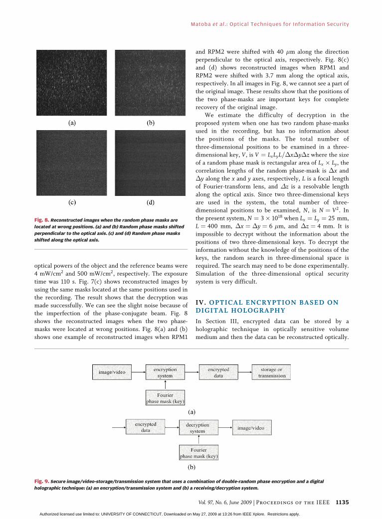
the imperfection of the phase-conjugate beam. Fig. 8shows the reconstructed images when the two phase-
masks were located at wrong positions. Fig. 8(a) and (b)
shows one example of reconstructed images when RPM1
and RPM2 were shifted with 40 �m along the directionperpendicular to the optical axis, respectively. Fig. 8(c)
and (d) shows reconstructed images when RPM1 and
RPM2 were shifted with 3.7 mm along the optical axis,
respectively. In all images in Fig. 8, we cannot see a part of
the original image. These results show that the positions of
the two phase-masks are important keys for complete
recovery of the original image.
We estimate the difficulty of decryption in theproposed system when one has two random phase-masks
used in the recording, but has no information about
the positions of the masks. The total number of
three-dimensional positions to be examined in a three-
dimensional key, V, is V ¼ LxLyL=�x�y�z where the size
of a random phase mask is rectangular area of Lx � Ly, the
correlation lengths of the random phase-mask is �x and
�y along the x and y axes, respectively, L is a focal lengthof Fourier-transform lens, and �z is a resolvable length
along the optical axis. Since two three-dimensional keys
are used in the system, the total number of three-
dimensional positions to be examined, N, is N ¼ V2. In
the present system, N ¼ 3� 1018 when Lx ¼ Ly ¼ 25 mm,
L ¼ 400 mm, �x ¼ �y ¼ 6 �m, and �z ¼ 4 mm. It is
impossible to decrypt without the information about the
positions of two three-dimensional keys. To decrypt theinformation without the knowledge of the positions of the
keys, the random search in three-dimensional space is
required. The search may need to be done experimentally.
Simulation of the three-dimensional optical security
system is very difficult.
IV. OPTICAL ENCRYPTION BASED ONDIGITAL HOLOGRAPHY
In Section III, encrypted data can be stored by a
holographic technique in optically sensitive volume
medium and then the data can be reconstructed optically.
Fig. 8. Reconstructed images when the random phase masks are
located at wrong positions. (a) and (b) Random phase masks shifted
perpendicular to the optical axis. (c) and (d) Random phase masks
shifted along the optical axis.
Fig. 9. Secure image/video-storage/transmission system that uses a combination of double-random phase encryption and a digital
holographic technique: (a) an encryption/transmission system and (b) a receiving/decryption system.
Matoba et al.: Optical Techniques for Information Security
Vol. 97, No. 6, June 2009 | Proceedings of the IEEE 1135
Authorized licensed use limited to: UNIVERSITY OF CONNECTICUT. Downloaded on May 27, 2009 at 13:26 from IEEE Xplore. Restrictions apply.

Digital holography [52]–[62] is a useful technique for
recording the fully complex field of a wave front. In line
with advances in imaging devices such as CCDs, digitalholography is accessible. We present in this section
encryption systems that combine double-random phase
encryption with a digital holographic technique. We can
encrypt in both Fourier domain [63] and Fresnel domain
[64], [65]. In this section the case in Fourier domain is
briefly reviewed. Encrypted data are stored in digital
format. Storing encrypted data in digital format enables us
to store, transmit, and decrypt the encrypted datadigitally. Either optical or computer decryption techniques
can be used with the system, depending on the specific
application.
A. Optical Encryption and Digital Retrieval byOff-Axis Digital Holography
We present a secure image/video-storage/transmission
system that uses a digital holographic technique [63].Fig. 9 shows the secure image/video-storage/transmission
system that uses a combination of double-random phase
encryption and a digital holographic technique. The data
are encrypted optically by the double-random phase
encryption technique and recorded as a digital hologram.
The optical key, that is, the Fourier phase mask, can also be
recorded as a digital hologram. The encrypted data can be
decrypted digitally with the hologram of the optical key.The experimental system is shown in Fig. 10. It consists
of a Mach–Zehnder interferometer. A He–Ne laser is used as
a coherent light source. The lower arm of the interferometer
is the optical path of the image encryption. The upper arm is
the reference wave. The input image to be encrypted is
bonded with the input phase mask at plane P1. This product
is Fourier transformed by lens L1 and is multiplied by the
Fourier phase mask at plane P2 and imaged onto the CCDcamera by the 4-f optical system of lenses L2 and L3. The
reference wave passes through the 4-f optical system of
lenses L4 and L5 to keep the spatial coherence.
At the CCD camera, a hologram is created by the
interference between the encrypted data and the slightly
inclined reference plane wave. Fig. 11 shows the input
images to be decrypted. These electronically reconstructed
images are obtained with an input phase mask without theFourier phase mask. Scattering that is due to the thickness
of the input random phase mask and the limitation on the
numerical aperture of the lens L1 are the reasons why the
images are somewhat noisy.
The digitally reconstructed encrypted images are
shown in Fig. 12. These images were obtained by inverse
Fourier transforming of the digital hologram of the
encrypted data. The original images cannot be recognized.The root-mean-square errors between the original images
UCONN and MEMORY shown in Fig. 11 and the
encrypted images shown in Fig. 12 are 6.6 and 7.3 for
8-bit pixel value, respectively. The digitally reconstructed
images that have been decrypted with the hologram of the
Fourier phase mask are shown in Fig. 13. Here one can see
the original images. The mean-square errors between the
original images UCONN and MEMORY shown in Fig. 11and the decrypted images shown in Fig. 13 are 1.1 and 0.97,
respectively. The experimental results demonstrate the
feasibility of the method.
B. Computational Optical Encryption System UsingDigital Holographic Technique
Virtual optical encryption system is useful because
there is no requirement to encrypt and record the object inan optical system. We show an encryption method of 3-D
object in a virtual optical system by use of phase
Fig. 10. Optical experimental setup. SF: spatial filter; CL: collimating
lens; Ms: mirrors; Ls: lenses; BSs: beam splitters; P1: input plane;
P2: Fourier plane.
Fig. 11. Digitally reconstructed input images.
Fig. 12. Digital holograms of (a) the encrypted data and (b) the Fourier
phase mask.
Fig. 13. Images that have been digitally reconstructed with the digital
hologram of both the encrypted data and the Fourier phase mask.
Matoba et al. : Optical Techniques for Information Security
1136 Proceedings of the IEEE | Vol. 97, No. 6, June 2009
Authorized licensed use limited to: UNIVERSITY OF CONNECTICUT. Downloaded on May 27, 2009 at 13:26 from IEEE Xplore. Restrictions apply.

modulation of an object wave [66]. The 3-D data used inthe encryption can be taken in optical holographic
recording or in virtual recording. Here we present that
the encryption is accomplished by a combination of a real
optical system and a virtual optical system. In this case, we
call this method hybrid optical encryption. As the real
optical system is used for recoding a 3-D object, we can
encrypt a real 3-D object. The virtual optical systems
shown in Figs. 14 and 15 are used for encryption anddecryption. The fundamental concept of encryption/
decryption is the same as mentioned in Section II.
Therefore only experimental results are shown here.
Note that a virtual phase mask (VPM) is used instead of
a real phase mask for encryption.
For 3-D objects, two dice, which are as large as
10� 10� 10 mm each are used. The distances from the
dice to the CCD are 180 and 270 mm, respectively. Forencryption, we calculate the wavefront at a VPM using a
computational diffraction integral. In this experiment, the
distance from the CCD to the VPM is assumed to be 30 mm.
To decrypt the encrypted digital hologram, a diffraction
integral is calculated based on the algorithm mentioned
above. With a correct position and a phase distribution of
the VPM, the decrypted 3-D objects are shown in
Fig. 16(a). Fig. 16(b) shows the decrypted 3-D objectsusing no information of the VPM. Fig. 16(c) and 16(d)
shows the decrypted 3-D objects if either the position or
phase distribution is wrong. In Fig. 16(c), the distance from
the CCD to the VPM is set to 31 mm. In Fig. 16(d), to
decrypt we use a VPM that has a phase distribution
independent from the VPM used in the encryption process.
Fig. 14. Scheme of an encryption step of a hybrid optical encryption
of a 3-D object using a digital holographic technique.
Fig. 15. Scheme of a decryption step of a hybrid optical encryption
of a 3-D object using a digital holographic technique.
Fig. 16. Decrypted 3-D objects using (a) both the correct position and phase distribution, (b) no information, (c) wrong position and
correct phase distribution, and (d) correct position and wrong phase distribution of a virtual phase mask. (e) The reconstructed
3-D object from a nonencrypted digital hologram.
Matoba et al.: Optical Techniques for Information Security
Vol. 97, No. 6, June 2009 | Proceedings of the IEEE 1137
Authorized licensed use limited to: UNIVERSITY OF CONNECTICUT. Downloaded on May 27, 2009 at 13:26 from IEEE Xplore. Restrictions apply.

The reconstructed objects from an original digital holo-
gram are shown in Fig. 16(e). From these experimental
results, if both the information of position and phase
distribution of the VPM are correct, the encrypted digitalhologram can be decrypted.
The performance of the hybrid optical encryption
method is evaluated quantitatively. The root-mean-square
error for 8-bit pixel value between the original image and
the decrypted image is introduced as a metric. The root-
mean-square errors between Fig. 16(a) and 16(e), 16(b)
and 16(e), 16(c) and 16(e), and 16(d) and 16(e) are 29, 40,
41, and 42, respectively. The reason the root-mean-squareerrors between Fig. 16(a) and 16(e) is not equal to zero is
mainly considered the limitation of the grayscale of digital
holograms, including encrypted digital holograms. In this
experiment, all digital holograms are recorded as grayscale
images with 8 bits. If a characteristic of holography is used,
parallax of the 3-D objects can be seen. Different
perspectives of the decrypted dice are shown. Fig. 17
shows three parallax and different focused objectscalculated from decrypted hologram at the VPM.
Fig. 17(a), 17(b), and 17(c) are obtained from the left
half, center, and right half regions of the decrypted
hologram with different distances from the hologram. A
different aspect in the figures can be seen.
V. OPTICAL TECHNIQUE FOR SECURITYBASED ON POLARIZATION
Optical validation and security verification methods using
optical correlation systems have been proposed. In some of
these systems, the validation is based on correlation with a
reference phase mask [1], [67]. Here, we present an optical
validation and security verification method that uses
polarization encoding [12]. In this method, a gray-scale
image such as a face or a fingerprint is bonded to apolarization encoded mask. The polarization-encoded
mask consists of randomly oriented linear polarizer’s
rotated at various angles from 0 to �. It can provide an
additional degree of freedom in securing the information
by combining with a phase code. We call this composite
image the polarization-encoded image. The polarization-
encoded image can not be distinguished from the normal
gray scale using an intensity sensitive device such as a CCD
camera because the polarization state cannot be detected
by a conventional intensity sensitive sensor. A nonlinearjoint transform correlator (JTC) [68] is used to provide the
verification system.
The polarization encoded optical security system is
described in detail. Let gðx; yÞ denote a nonnegative and
nonpolarized image to be identified. The image gðx; yÞ is
bonded to the polarization encoded mask as shown in
Fig. 18 to generate a polarization-encoded image.
To verify a polarization-encoded image, we opticallycompare the polarization-encoded image with a reference
polarization mask. We use a nonlinear random JTC optical
system for verification. As shown in Fig. 19, the
polarization-encoded image and the reference polarization
mask are placed side by side in the input plane of the
correlator. The input images are Fourier transformed using
a lens. Then the joint power spectrum of the polarization
encoded image and the reference polarization mask iscaptured by a CCD camera. The joint power spectrum can
be nonlinearly transformed to provide a high discrimina-
tion capability. Then the joint power spectrum is inverse
Fourier transformed. Finally we obtain the correlation
between the polarization encoded image and the reference
polarization mask. Here only correlational signals of JTC
are shown but central signals on the optical axis and
conjugate signals are not shown.
Fig. 17. Decrypted 3-D objects that have a different aspect: (a) front focused reconstructed objects from the left-half region,
(b) middle focused reconstructed objects from the center region, and (c) back focused reconstructed image from the right-half
region of the decrypted digital holograms, respectively.
Fig. 18. Polarization-encoded image for an optical verification system.
Matoba et al. : Optical Techniques for Information Security
1138 Proceedings of the IEEE | Vol. 97, No. 6, June 2009
Authorized licensed use limited to: UNIVERSITY OF CONNECTICUT. Downloaded on May 27, 2009 at 13:26 from IEEE Xplore. Restrictions apply.

When the encoding polarization mask is the same as
the reference polarization mask, a strong correlation is
produced. When the two polarization masks are not
identical, the cross-correlation signal is lower than the
cross-correlation signal when the polarization masks are
the same. Thus, we can verify the image in terms of thecorrelation between the polarization encoded mask and
the reference polarization mask.
We present optical experiments to demonstrate the
system. The experimental setup is the same as the system
shown in Fig. 19. A human face on photographic film is
used as a gray-scale image. The dimensions of the input
image are 6� 6 mm2. For simplicity, the polarization
masks consisting of 200 � 200 random binary (horizontalor vertical) linear polarizers arrays [69] are used. The
arrays were made of two-surface, relief-etched birefringent
substrates joined face to face. Each pixel size is
30� 30 �m2. A He–Ne laser is used as a coherent light
source. A lens with a focal length of 200 mm is used for
optical Fourier transformation. The joint power spectrum
is captured by a CCD camera. Then it is sampled to
512 � 480 pixels and quantized to 8 bits by a framegrabber equipped in a personal computer. The digitized
joint power spectrum is Fourier transformed by using fast
Fourier transform algorithm to obtain the correlation
output. Fig. 20 shows the correlation results. Fig. 20(a)
corresponds to the case when the reference polarization
mask is the same as the encoding polarization mask.
Fig. 20(b) corresponds to the case when the reference
mask is different from the encoding mask.We demonstrated an optical validation and security
verification system using polarization encoding of input
images. The polarization encoding can provide an addi-
tional degree of freedom to secure information usingoptical technologies. The polarization encoding can be
combined with phase encoding scheme, to enhance the
validation and security verification of the system. Optical
experiments demonstrate the performance of the system.
VI. OPTICAL ID TAGS
In this section, we describe an example of applications ofoptical encryption with authentication. The presented
system is a compact technique for encryption-verification
that relates four elements: multifactor encryption, distor-
tion-invariant ID tag, near infrared (NIR) readout, and
optical processor. A highly-reliable security system is
obtained by joining the advantages of these four elements.
The designed NIR ID tag exhibits remarkable character-
istics such as distortion-invariance, easy and economicaltag production and robustness. The encrypted information
included in the ID tag is verified by comparing the decoded
signal with a reference that, in turn, can be a single or a
compound signature. In the steps of the procedure we
show the benefits of using combined optical and digital
image processing techniques implemented by optoelec-
tronic systems. The proposed optical ID tags are not
intended for strictly digital implementation as there areother technologies based on electronic computing. Optical
ID tags are best suited for the combined optical-digital
domain as optics provides useful resources for remote,
real-time, automatic and reliable signal verification.
Optical security systems usually deal with a single primary
image (an object, a signature, or a biometric signal) as au-
thenticator. However, security can be reinforced by combin-
ing different authenticators. In such a case, a Boolean ANDoperation has to be performed for each factor’s authentication
results so all must be affirmative before final authentication is
satisfied [19]. The selection of authenticators is a crucial step
because the identification of an element (object or person or
both) is based on them. They must uniquely represent the
element whose identity is to be validated on a basis of signal
recognition. Frequently, the authenticators are images such
as logotypes, bar codes, alphanumerical signs, signatures,biometric information, and random sequences. Biometric
images such as fingerprints, face, hand, iris, and retina are
more and more considered in authentication mechanisms
because biometrics is based on something intrinsic to a person
(something the person is) in contrast to other schemes based
on either something a person knows (e.g., a password) or has
(e.g., a metal key, an ID card) [19].
In this section we consider multiple signals to identify aperson, an object (for instance, a vehicle or a parcel) or
both. The information is combined using a multifactor
encryption-authentication technique that reinforces opti-
cal security by allowing the simultaneous AND-verification
of four primary images [20]. This technique is attractive
for high-security purposes that require multiple reliable
authentications [20], [27]. There is no a priori constraint
Fig. 19. Polarization-encoded optical verification system using a JTC.
Matoba et al.: Optical Techniques for Information Security
Vol. 97, No. 6, June 2009 | Proceedings of the IEEE 1139
Authorized licensed use limited to: UNIVERSITY OF CONNECTICUT. Downloaded on May 27, 2009 at 13:26 from IEEE Xplore. Restrictions apply.

about the type of primary images to encode. In the example
(Fig. 21) a combination of one biometric (to validate the
authorised person), two characteristic images (to validatethe content and the origin of a parcel) and one random
phase sequence (to act as key code) are considered. The
vessel distribution of a retina fundus image, which is
stable, accurate, and very effective information for
authentication, is used as biometric signal. In the example,
a low resolution binary retina scanning is considered. The
key phase code is shared by the database of the
authentication processor and is introduced as a degree offreedom to codify, for instance, the key of the day. These
four reference primary images, double-phase encoded
(Section VI-A) and encrypted in an ID tag (Section VI-B),
are compared with the input images obtained in situ fromthe person and the parcel whose authentication is wanted.
A. Complex-Amplitude Encrypted FunctionThe complex-amplitude encrypted function of multiple
signatures (multifactor) in a single complex-valued distri-
bution mðxÞ is described here. Let rðxÞ, sðxÞ, bðxÞ, and nðxÞbe the multiple authenticators or reference primary images
(for instance, those in Fig. 21), in one-dimensional notationfor simplicity. All the four primary images sðxÞ, bðxÞ, and nðxÞ
Fig. 21. Reference primary images to consider as multiple authenticators in the multifactor encryption-authentication technique.
(a) Biometric sðxÞ; (b) parcel content rðxÞ; (c) key code bðxÞ; (d) parcel origin nðxÞ.
Fig. 20. Correlation results by optical experiments using a conventional JTC: (a) reference polarization mask identical to encoding
polarization mask and (b) reference polarization mask different from encoding polarization mask.
Matoba et al. : Optical Techniques for Information Security
1140 Proceedings of the IEEE | Vol. 97, No. 6, June 2009
Authorized licensed use limited to: UNIVERSITY OF CONNECTICUT. Downloaded on May 27, 2009 at 13:26 from IEEE Xplore. Restrictions apply.
are normalized positive functions distributed in [0,1]. These
images can be phase-encoded to yield trðxÞ, tsðxÞ, t2bðxÞ, tnðxÞthat are generically defined by tf ðxÞ ¼ expfi�fðxÞg. Thefully-phase encrypted function containing the multi-
factor authenticators is given by the equation
mðxÞ ¼ trþ2bðxÞ � tsðxÞ � FT�1 tnðxÞ½ � (6.1)
where trþ2bðxÞ ¼ trðxÞt2bðxÞ ¼ expfi�rðxÞg expfi2�bðxÞg.The encrypted function is complex-amplitude valued. It can
be either optically generated by using an optical hardware
equivalent to a JTC or computed and electronically
implemented using conventional techniques for computer
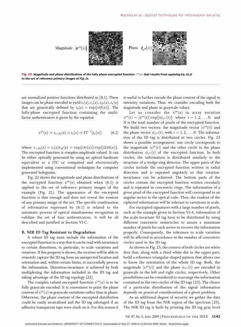
generated holograms.Fig. 22 shows the magnitude and phase distributions of
the encrypted function mðxÞ obtained when (6.1) is
applied to the set of reference primary images of the
example (Fig. 21). The appearance of the encrypted
function is dim enough and does not reveal the content
of any primary image of the set. The specific combination
of information expressed by (6.1) is related to the
automatic process of optical simultaneous recognition tovalidate the set of four authenticators. It will be all
described and justified in Section VI-C.
B. NIR ID Tag Resistant to DegradationA robust ID tag must include the information of the
encrypted function in a way that it can be read with invariance
to certain distortions, in particular, to scale variations and
rotations. If this property is shown, the receiver will be able toremotely capture the ID tag from an unexpected location and
orientation and, within certain limits, to successfully process
the information. Distortion-invariance is achieved by both
multiplexing the information included in the ID tag and
taking advantage of the ID tag topology [22].
The complex valued encrypted function mðxÞ is to be
fully grayscale encoded. It is convenient to print the phase
content of mðxÞ in grayscale variations rather than in phase.Otherwise, the phase content of the encrypted distribution
could be easily neutralized and the ID tag sabotaged if an
adhesive transparent tape were stuck on it. For this reason it
is useful to further encode the phase content of the signal in
intensity variations. Thus, we consider encoding both the
magnitude and phase in grayscale values.Let us consider the mðxÞ in array notation
mðtÞ ¼ j mðtÞj expfi mðtÞg where t ¼ 1; 2; . . . N, and
N is the total number of pixels of the encrypted function.
We build two vectors: the magnitude vector j mðtÞj and
the phase vector mðtÞ, with t ¼ 1; 2; . . . N. The informa-
tion of the ID tag is distributed in two circles. Fig. 23
shows a possible arrangement: one circle corresponds to
the magnitude j mðtÞj and the other circle to the phasedistribution mðtÞ of the encrypted function. In both
circles, the information is distributed similarly to the
structure of a wedge-ring detector. The upper parts of the
circles include the encrypted function written in radial
direction and is repeated angularly so that rotation-
invariance can be achieved. The bottom parts of the
circles contain the encrypted function written circularly
and is repeated in concentric rings. The information of agiven pixel of the encrypted function will correspond to an
angular sector in the optical code. Thus, the readout of the
ciphered information will be tolerant to variations in scale.
For encrypted signatures with a large number of pixels,
such as the example given in Section VI-A, information of
the scale-invariant ID tag have to be distributed by using
different concentric semicircles to assure a minimum
number of pixels for each sector to recover the informationproperly. Consequently, the tolerance to scale variation
will be affected in accordance to the number of concentric
circles used in the ID tag.
As shown in Fig. 23, the centers of both circles are white
dots that, along with a third white dot in the upper part,
build a reference triangular shaped pattern that allows one
to know the orientation of the whole ID tag. Both, the
magnitude j mðtÞj and the phase mðtÞ are encoded ingrayscale in the left and right circles, respectively. Other
possibilities can be considered to rearrange the information
contained in the two circles of the ID tags [23]. The choice
of a particular distribution of the signal information
depends on practical considerations of a given problem.
As an additional degree of security we gather the data
of the ID tag from the NIR region of the spectrum [25].
The NIR ID tag is built by printing the ID tag gray level
Fig. 22. Magnitude and phase distributions of the fully phase encrypted function mðxÞ that results from applying Eq. (6.1)
to the set of reference primary images of Fig. 21.
Matoba et al.: Optical Techniques for Information Security
Vol. 97, No. 6, June 2009 | Proceedings of the IEEE 1141
Authorized licensed use limited to: UNIVERSITY OF CONNECTICUT. Downloaded on May 27, 2009 at 13:26 from IEEE Xplore. Restrictions apply.

distribution with a common laser printer on a black
cardboard. In the visible spectrum, the whole information
is completely hidden to either the naked eye or common
cameras operating in the visible region of the spectrum.When looking at the ID tag, both the eye and the common
camera would see just a black patch. Thus, it is not possible
for them to know neither the kind of information in-
cluded in the ID tag nor the exact position of this ID tag
over the item under surveillance. Only NIR InGaAs cam-
eras or conventional monochrome CCD cameras without
the IR cut-off filter are able to detect the information of
concern.Using the procedure described, the information is also
redundantly written, so that we obtain an improved
resistance to noise and other sorts of degradation such as
free space propagation or damages due to common
handling (e.g., scratches) [25]. An auto-destruction mech-
anism of the ID tag has been proposed to invalidate the ID
tag in case of having cuts or other damage produced by any
attempt of tampering [25]. For example, a reservoir ofblack ink (black in terms of NIR illumination) under the
ID tag. When the tag is cut, the ink is spread throughout it,
the tag cannot be properly read, and the processor gives an
alarm.
The ID tag represented in Fig. 24. The NIR ID tag is
captured by an NIR sensitive device. The information
contained in the ID tag stuck on the parcel has to be
compared with the input signals contained, for instance, ina card. In this way, it is possible to verify the identity of
both the card holder and the parcel. When the ID tag is
captured, the encrypted information is decoded following
a deciphering procedure that is the reverse of that
described above. From one circle the magnitude isobtained and from the other, the phase distribution.
Once the border between the rotation-invariant area and
scale-invariant area is extracted (the axis in Fig. 23), the
signature in vector notation mðtÞ can be decoded either
from the rotation or the scale-invariant region.
From the rotation-invariant region, the optical code can
be read out by using a linear array detector placed in any
radius of the semicircle, from the center to the exterior of thecode. Not only is a single code read along a unique radial
direction for decoding, but a median value from several
radial codes is computed to increase robustness against noise
and other sorts of signal degradation. Pixels are written back
into matrix notation prior to dechiphering the signature
mðxÞ. Following this procedure, the encrypted signature
can be recovered whether the ID tag is captured in its
original orientation or rotated. Similarly, mðtÞ can berecovered by reading the ID tag in circular rings in the scale-
invariant region. To minimize errors in the reading process,
the median value of pixels located in neighbour rings is
computed. The signature is then written in matrix notation
mðtÞ and decrypted. The optical code will be recovered
when the ID tag is captured with its original size or scaled.
On the other hand, diffraction could distort the
reflected ID tag field for long distances. If the systemused the diffracted pattern as it was captured by the
Fig. 23. Synthesis of a rotation and scale invariant ID tag from the encrypted function ðxÞ.
Matoba et al. : Optical Techniques for Information Security
1142 Proceedings of the IEEE | Vol. 97, No. 6, June 2009
Authorized licensed use limited to: UNIVERSITY OF CONNECTICUT. Downloaded on May 27, 2009 at 13:26 from IEEE Xplore. Restrictions apply.

receiver, the correlation could be poor even in the case of a
correct signal. We can overcome this by comparing the
received field with a precalculated pattern that takes intoaccount the ID tag after free space propagation for a given
distance. In such a case, we may need to know the distance
between the receiver and the tag.
C. Optical Processor for Multifactor VerificationThe multifactor authentication technique involves an
optical processor that consists of a combined nonlinear
JTC and a classical 4f -correlator [70] for simultaneousAND authentications of multiple images (Fig. 25). We
describe the principles of the method for a four-factor
authentication taking into account that the encrypted
function mðxÞ, which has been decoded from the ID tag,
was built according to (6.1).
Let pðxÞ, qðxÞ, dðxÞ, and mðxÞ, denote the positive and
normalized input images to compare with the set of reference
images, rðxÞ, sðxÞ, bðxÞ and nðxÞ, respectively. In the first
step, the ID tag mðx� aÞ and one phase encoded input
image, for instance tpðxþ aÞ ¼ expfj�pðxþ aÞg, are dis-
played side-by-side a distance tpðxþ aÞ apart on theinput plane of the nonlinear JTC illuminated by coherent
light (Fig. 25). The phase distribution t2dðxþ aÞ ¼expfj2�dðxþ aÞg is placed against the screen where the
input tpðxþ aÞ is displayed. Consequently, the amplitude
distribution in the input plane is mðx� aÞ þ tpþ2dðxþ aÞ.A CCD sensor placed in the Fourier plane of the JTC cap-
tures the intensity distribution Ið�Þ of the joint power
spectrum,
Ið�Þ ¼ FT mðx� aÞ þ tpþ2dðxþ aÞ� ��� ��2: (6.2)
The development of (6.2) gives the classical four terms of
which two are interesting because they convey the cross-correlation signals that lead to spatially separated distribu-
tions in the output plane. These two terms are:
Term 1 : FT� mðxÞ½ �FT tpþ2dðxÞ� �
expfj2a�g¼ T�rþ2bð�ÞT�s ð�Þt�nð�ÞTpþ2dð�Þ expfj2a�g;
Term 2 : FT mðxÞ½ �FT� tpþ2dðxÞ� �
expf�j2a�g¼ Trþ2bð�ÞTsð�Þtnð�ÞT�pþ2dð�Þ expf�j2a�g; (6.3)
where a function in capital letter indicates the Fourier
transform of the function in small letter and � is the spatial
frequency coordinate. Terms 1 and 2 of (6.3) can be modified
according to a variety of nonlinear techniques of the gene-
ral form
NLk Ið�Þf g ¼ Ið�Þ Ið�Þj jk�1; (6.4)
Fig. 24. Diagram of the ID tag readout, signature decryption and comparison with the input signal for verification.
Fig. 25. Optical processor for multifactor authentication.
Matoba et al.: Optical Techniques for Information Security
Vol. 97, No. 6, June 2009 | Proceedings of the IEEE 1143
Authorized licensed use limited to: UNIVERSITY OF CONNECTICUT. Downloaded on May 27, 2009 at 13:26 from IEEE Xplore. Restrictions apply.

where k 2 ½0; 1� defines the strength of the nonlinearityand can vary from the linear case ðk ¼ 1Þ to the phase
extraction ðk ¼ 0Þ or pure phase correlation (PPC).
The resultant nonlinearly modified joint power spec-
trum ((6.4)) is displayed on the Fourier plane of a 4f -
classical correlator (Fig. 25). There, a transparency with
the phase distribution tmð�Þ is placed against the screen.
The input image qðxÞ is phase encoded and displayed
on the input plane of the 4f -correlator. Behind the Fourierplane, Terms 1 and 2 of (6.3) are converted into:
Term 1 : Tqð�ÞT�s ð�Þ Tsð�Þj jk�1h i
� T�rþ2bð�ÞTpþ2dð�Þ Trþ2bð�ÞTpþ2dð�Þ�� ��k�1
h i
� t�nð�Þtmð�Þ� �
expfj2a�g;
Term 2 : Tqð�ÞTsð�Þ Tsð�Þj jk�1h i
� Trþ2bð�ÞT�pþ2dð�Þ Trþ2bð�ÞTpþ2dð�Þ�� ��k�1
h i
� tnþmð�Þ½ � expf�j2a�g: (6.5)
If the information contained in the ID tag corresponds to a
positive validation, then the multiple AND condition
rðxÞ ¼ pðxÞ AND sðxÞ ¼ qðxÞ AND bðxÞ ¼ dðxÞ AND
nðxÞ ¼ mðxÞ is fulfilled. In such a case, if the phase
extraction is applied ðk ¼ 0Þ and provided the system is
free of noise and distortions, Term 1 of (6.5) simplifies into
jTsð�Þj expfj2a�g, which represents a wavefront with all itscurvature cancelled [70] that focuses on a sharp multifactor
autocorrelation peak centered in x ¼ �2a of the output
plane (Fig. 25). From (6.5), the output intensity distribu-
tion corresponding to Term 1 is the cross-correlation of
autocorrelation signals given by
ACPOF tsðxÞ½ � ? AC�PPC trþ2bðxÞ½ ���
?AC�CMF TnðxÞ½ � � ðxþ 2aÞ��2; (6.6)
where ? denotes cross-correlation, and subindices CMF,
POF, PPC indicate the sort of filter involved in the
autocorrelation signal (CMF stands for classical matchedfilter, POF for phase-only filter, and PPC for pure phase
correlation). Since autocorrelation peaks are usually sharp
and narrow, particularly those for POF and PPC, we expect
that the cross-correlation of such autocorrelation signals
will be even sharper and narrower [71]. Consequently, the
information contained in Term 1, allows reinforced
security verification by simultaneous multifactor authen-
tication. On the other hand, when the multiple ANDcondition rðxÞ ¼ pðxÞ AND sðxÞ ¼ qðxÞ AND bðxÞ ¼ dðxÞAND nðxÞ ¼ mðxÞ is fulfilled, and the phase extraction
k ¼ 0 is considered, Term 2 of (6.5) becomes
½T2s ð�Þ=jTsð�Þj�t2nð�Þ expf�j2a�g, which does not yield
any interesting result for recognition purposes. If
pðxÞ 6¼ rðxÞ or qðxÞ 6¼ sðxÞ or bðxÞ 6¼ dðxÞ or nðxÞ 6¼ mðxÞ,Term 1 contains a cross correlation signal that is, in general,
broader and less intense than the multifactor autocorrela-tion peak of (6.6).
In the experiment, the set of input images can be
equal to the reference set, partly different or totally
different. Fig. 26 contains some input images, different
from those reference primary images of Fig. 21, that are to
be considered in the experiments. A distortion-invariant
ID tag containing the multifactor encrypted information
was produced by printing the ID tag using a commonHewlett Packard laser printer on a black cardboard. The
printed ID tag was uniformly illuminated by ordinary
incandescent light bulbs and grabbed lately by an NIR
InGaAs camera [Fig. 27(a)] with sensitivity in the NIR
region (900–1700 nm). This result shows a feasible way
to obtain NIR ID tags using common materials. If the ID
tag was registered using a monochrome camera sensitive
in the visible region of the spectrum, its content wouldnot be perceived at naked eye as it would be completely
black. The ID tag was rotated 7 degrees from horizontal
position [Fig. 27(a)]. The scrambled four factors (primary
images sðxÞ, rðxÞ, bðxÞ, nðxÞ) were decrypted and
introduced as a reference for the validation of the set of
input image qðxÞ, pðxÞ, dðxÞ, mðxÞ. Fig. 27(b)–(e) shows
the output intensity distribution corresponding to the
Term 1 of the multifactor correlation with phaseextraction ðk ¼ 0Þ for different situations that correspond
to the most relevant identification results obtained in the
Fig. 26. Images to consider in the experiments that involve encryption in the ID tag. (a) Biometric aðxÞ; (b) parcel content pðxÞ;(c) key code dðxÞ; (d) parcel origin mðxÞ.
Matoba et al. : Optical Techniques for Information Security
1144 Proceedings of the IEEE | Vol. 97, No. 6, June 2009
Authorized licensed use limited to: UNIVERSITY OF CONNECTICUT. Downloaded on May 27, 2009 at 13:26 from IEEE Xplore. Restrictions apply.

experiment. For the sake of comparison, the maximum
intensity value of the output planes is normalized to the
case where the set of input images coincide with the set of
reference primary images (satisfactory verification)[Fig. 27(b)], and thus the result is given by (6.6). Also
for comparison, the output correlation signal of the
processor is depicted for an ideal ID tag and for the
experimentally captured ID tag.
If just one signal among the four factors (biometric,
parcel content, origin, or key code) or even the whole set
of input images does not correspond to the set introduced
in de ID tag, the resulting output planes show an
insignificant intensity peak that hardly projects over the
background [Fig. 27(c), (d)]. An appropriate threshold
value will indicate negative verification.Finally, if the ID tag is slightly scratched due to friction
[Fig. 27(e)], a positive verification result is obtained when
the whole set of input images coincides with the
authorized factors included in the ID tag. If one or more
input images do not coincide with the set of primary
images, a negative result is obtained in the verification
process. In the examples analyzed, there is a good
Fig. 27. Experimental and simulated results for the verification system by using distorted NIR multifactor ID tags: (a) Optical distortion-invariant
ID tag (rotation angle 7 degrees) experimentally captured by using an NIR XEVA (b) Positive validation when the four identifying factors coincide
with the information included in the ID tag; Negative results obtained when one (c) or more factors (d) do not coincide with the set of primary
images; (e) Positive validation with a partially scratched ID tag. In all cases, verification outputs are normalized to the positive validation (b).
Matoba et al.: Optical Techniques for Information Security
Vol. 97, No. 6, June 2009 | Proceedings of the IEEE 1145
Authorized licensed use limited to: UNIVERSITY OF CONNECTICUT. Downloaded on May 27, 2009 at 13:26 from IEEE Xplore. Restrictions apply.

agreement between the experimental and the predictedverification results.
VII. CONCLUSION
We have presented an overview of the potential of optical
techniques in encryption and security applications. The
encryption methods based on random phase modulation
and other encryption methods based on multidimensionalkeys have been presented. When using optical encryption,
many degrees of freedom to manipulate the physical
parameters of optical waves can be used. Therefore, a
higher level of security may be achieved. The encrypted
data can be stored either in optical or digital format. In
encrypted optical memory, large amounts of data storage
as much as 1 Tera Bytes/optical disc and fast data transfer
rate of 1 Gbps can be expected which can be optically
secured. In digital holography, 3-D data can be encryptedoptically secured and provided to remote users via data
communication channels. In security applications, en-
crypted data have been used in the authentication process.
Multiple signatures with IR imaging can be employed for
distortion-invariant optical ID tags for authentication and
verification. The techniques described in this work can be
useful to protect, store or transmit classified data, to
control the access to restricted areas, where the highlysecure identification of a person, an object or both might
be required. h
Acknowledgment
The authors would like to thank Dr. Fang Xu and
Prof. Yeshaiahu Fainman at the University of California,
San Diego, for fabricating the polarization masks.
REF ERENCE S
[1] B. Javidi and J. L. Horner, BOptical patternrecognition for validation and securityverification,[ Opt. Eng., vol. 33,pp. 1752–1756, 1994.
[2] J. L. Horner and B. Javidi, Opt. Eng., vol. 38,Special Issue on Optical Security, 1999.
[3] B. Javidi, Optical and Digital Techniques forInformation Security. New York: Springer,2005.
[4] C. H. Bennett, F. Bessette, G. Brassard,L. Salvail, and J. Smolin, BExperimentalquantum cryptography,[ J. of Cryptology,vol. 5, pp. 3–28, 1992.
[5] P. Refregier and B. Javidi, BOptical imageencryption based on input plane and Fourierplane random encoding,[ Opt. Lett., vol. 20,pp. 767–769, 1995.
[6] H. Kogelnik, BHolographic image projectionthrough inhomogeneous media,[ Bell Syst.Tech. J., vol. 44, pp. 2451–2455, 1965.
[7] N. Towghi, B. Javidi, and Z. Luo, BFully phaseencrypted image processor,[ J. Opt. Soc.Amer. A, vol. 16, pp. 1915–1927, 1999.
[8] O. Matoba and B. Javidi, BEncrypted opticalmemory system using three-dimensional keysin the Fresnel domain,[ Opt. Lett., vol. 24,pp. 762–764, 1999.
[9] O. Matoba and B. Javidi, BEncrypted opticalstorage with wavelength-key and randomphase codes,[ Appl. Opt., vol. 38,pp. 6785–6790, 1999.
[10] X. Tan, O. Matoba, Y. Okada-Shudo, M. Ide,T. Shimura, and K. Kuroda, BSecure opticalmemory system with polarizationencryption,[ Appl. Opt., vol. 40, pp. 2310–2315,2001.
[11] O. Matoba and B. Javidi, BSecure holographicmemory by double random polarizationencryption,[ Appl. Opt., vol. 43,pp. 2915–2919, 2004.
[12] B. Javidi and T. Nomura, BPolarizationencoding for optical security systems,[ Opt.Eng., vol. 9, pp. 2439–2443, 2000.
[13] N. K. Nishchal, J. Joseph, and K. Singh, BFullyphase encryption using fractional Fouriertransform,[ Opt. Eng., vol. 42, pp. 1583–1586,2003.
[14] P. C. Mogensen and J. Gluckstad, BPhase-onlyoptical encryption,[ Opt. Lett., vol. 25,pp. 566–568, 2000.
[15] S. Fukushima, T. Kurokawa, and Y. Sakai,BImage encipherment based on opticalparallel processing using spatial lightmodulator,[ IEEE Trans. Photonics Technol.Lett., vol. 3, pp. 1133–1135, 1991.
[16] B. Javidi, BReal-time remote identificationand verification of objects using optical IDtags,[ Opt. Eng., vol. 42, pp. 1–3, 2003.
[17] E. Perez-Cabre and B. Javidi, BScale androtation-invariant ID tags for automaticvehicle identification and authentication,[IEEE Trans. Vehicular Technology, vol. 54,pp. 1295–1303, 2005.
[18] J. F. Barrera, R. Henao, M. Tebaldi,R. Torroba, and N. Bolognini, BMultiplexingencrypted data by using polarized light,[ Opt.Commun., vol. 260, pp. 109–112, 2006.
[19] L. O’Gorman, BComparing passwords, tokens,and biometrics for user authentication,[ Proc.IEEE, vol. 91, pp. 2021–2040, 2003.
[20] M. S. Millan, E. Perez-Cabre, and B. Javidi,BMultifactor authentication reinforces opticalsecurity,[ Opt. Lett., vol. 31, pp. 712–723,2006.
[21] S. K. Kaura, D. P. Chhachhia, andA. K. Aggarwal, BInterferometric moirepattern encoded security holograms,[ J.Optics A, Pure and Applied Optics, vol. 8,pp. 51–67, 2006.
[22] E. Perez-Cabre, M. S. Millan, and B. Javidi,BDesign of distortion-invariant optical ID tagsfor remote identification and verification ofobjects,[ in Physics of the Automatic TargetRecognition, F. Sadjadi and B. Javidi, Eds.New York: Springer, 2007.
[23] E. Perez-Cabre, M. S. Millan, and B. Javidi,BRemote optical ID tag recognition andverification using fully spatial phasemultiplexing,[ in Proc. SPIE, 2005, vol. 5986,p. 598602.
[24] E. Perez-Cabre, M. S. Millan, and B. Javidi,BVisible and NIR spectral band combinationto produce high security ID tags for automaticidentification,[ in Proc. SPIE, 2006, vol. 6394,p. 63940I.
[25] E. Perez-Cabre, M. S. Millan, and B. Javidi,BNear infrared multifactor identificationtags,[ Opt. Express, vol. 15, pp. 15615–15627,2007.
[26] S. Der, A. Chan, N. Nasrabadi, and H. Kwon,BAutomated vehicle detection in
forward-looking infrared imagery,[ Appl. Opt.,vol. 43, pp. 333–348, 2004.
[27] M. S. Millan, E. Perez-Cabre, and B. Javidi,BHigh secure authentication by opticalmultifactor ID tags,[ in Proc. SPIE, 2006vol. 6394, p. 63940J.
[28] ATR Definitions and Performance Measures,Automatic Target Recognizers WorkingGroup (ATRWG) Publications, no. 86-001[1986.
[29] T. Kotzer, J. Rosen, and J. Shamir, BPhaseextraction pattern recognition,[ Appl. Opt.,vol. 31, pp. 1126–1137, 1992.
[30] R. Pappu, B. Recht, J. Taylor, andN. Gershenfeld, BPhysical one-wayfunctions,[ Science, vol. 297, pp. 2026–2030,2002.
[31] F. Goudail, F. Bollaro, B. Javidi, andP. Refregier, BInfluence of a perturbation in adouble random phase encoding system,[ J.Opt. Soc. Amer. A, vol. 15, pp. 2629–2638,1998.
[32] Y. Frauel, A. Castro, T. Naughton, andB. Javidi, BResistance of the double randomphase encryption against various attacks,[Opt. Express, vol. 15, pp. 10 253–10 265,2007.
[33] T. J. Naughton, B. M. Hennelly, andT. Dowling, BIntroducing secure modes ofoperation for optical encryption,[ J. Opt. Soc.Amer. A, vol. 25, pp. 2608–261, 2008.
[34] P. J. van Heerden, BTheory of informationstorage in solids,[ Appl. Opt., vol. 2,pp. 393–400, 1963.
[35] H. J. Coufal, D. Psaltis, and G. Sincerbox,Holographic Data Storage. New York:Springer, 2000.
[36] L. Hesselink, S. S. Orlov, and M. C. Bashaw,BHolographic data storage systems,[ Proc.IEEE, vol. 92, pp. 1231–1280, 2004.
[37] J. F. Heanue, M. C. Bashaw, and L. Hesselink,BVolume holographic storage and retrieval ofdigital data,[ Science, vol. 265, pp. 749–752,1994.
[38] L. d’Auria, J. P. Huignard, and E. Spitz,BHolographic read-write memory andcapacity enhancement by 3-D storage,[ IEEETrans. Magn., vol. 9, pp. 83–94, 1973.
[39] H. Horimai and X. Tan, BCollinear for aholographic versatile disk,[ Appl. Opt., vol. 45,pp. 910–914, 2006.
Matoba et al. : Optical Techniques for Information Security
1146 Proceedings of the IEEE | Vol. 97, No. 6, June 2009
Authorized licensed use limited to: UNIVERSITY OF CONNECTICUT. Downloaded on May 27, 2009 at 13:26 from IEEE Xplore. Restrictions apply.

[40] B. Javidi, G. Zhang, and J. Li, BEncryptedoptical memory using double-random phaseencoding,[ Appl. Opt., vol. 36, pp. 1054–1058,1997.
[41] G. Unnikrishnan, J. Joseph, and K. Singh,BOptical encryption system that uses phaseconjugation in a photorefractive crystal,[Appl. Opt., vol. 37, pp. 8181–8186, 1998.
[42] O. Matoba and B. Javidi, BEncrypted opticalstorage with angular multiplexing,[ Appl. Opt.,vol. 38, pp. 7288–7293, 1999.
[43] X. Tan, O. Matoba, T. Shimura, K. Kuroda,and B. Javidi, BSecure optical storage that usesfully phase encryption,[ Appl. Opt., vol. 39,pp. 6689–6694, 2000.
[44] T. Nomura, S. Mikan, Y. Morimoto, andB. Javidi, BSecure optical data storage withrandom phase key codes by use of aconfiguration of a joint transform correlator,[Appl. Opt., vol. 42, pp. 1508–1514, 2003.
[45] H. F. Heanue, M. C. Bashaw, andL. Hesselink, BEncrypted holographic datastorage based on orthogonal-phase-codemultiplexing,[ Appl. Opt., vol. 34,pp. 6012–6015, 1995.
[46] O. Matoba and B. Javidi, BSecure holographicmemory by double random polarizationencryption,[ Appl. Opt., vol. 43, no. 14,pp. 2915–2919, 2004.
[47] O. Matoba, Y. Yokohama, M. Miura, K. Nitta,and T. Yoshimura, BReflection-typeholographic disk memory with random phaseshift multiplexing,[ Appl. Opt., vol. 45,pp. 3270–3274, 2006.
[48] C. C. Sun and W. C. Su, BThree-dimensionalshift selectivity of random phase encoding involume holograms,[ Appl. Opt., vol. 40,pp. 1253–1260, 2001.
[49] J. F. Barrera, R. Henao, M. Tebaldi,R. Torroba, and N. Bolognini, BMultiplexingencryption-decryption via lateral shifting of arandom phase mask,[ Opt. Commun., vol. 259,pp. 532–536, 2006.
[50] M. Toishi, M. Hara, K. Tanaka, T. Tanaka, andK. Watanabe, BNovel encryption methodusing multi reference patterns in coaxialholographic data storage,[ Jpn. J. Appl. Phys.,vol. 46, pp. 1781–3775, 2007.
[51] T. Nomura, E. Nitanai, T. Numata, andB. Javidi, BDesign of input phase mask for thespace bandwidth of the optical encryptionsystem,[ Opt. Eng., vol. 45, p. 017006, 2006.
[52] I. Yamaguchi and T. Zhang, BPhase-shiftingdigital holography,[ Opt. Lett., vol. 22,pp. 1268–1270, 1997.
[53] W. Osten, T. Baumbach, and W. Juptner,BComparative digital holography,[ Opt. Lett.,vol. 27, pp. 1764–1766, 2002.
[54] T. Kreis, Handbook of HolographicInterferometry. Weinheim, Germany: WileyVCH, 2005.
[55] Y. Frauel, T. Naughton, O. Matoba,E. Tajahuerce, and B. Javidi,BThree-dimensional imaging and processingusing computational holographic imaging,[Proc. IEEE, vol. 94, pp. 636–653, 2006.
[56] J. W. Goodman and R. Lawrence, BDigitalimage formation from electronically detectedholograms,[ Appl. Phys. Lett., vol. 11,pp. 77–79, 1967.
[57] J. Rosen, BThree-dimensional optical Fouriertransform and correlation,[ Opt. Lett., vol. 22,pp. 964–966, 1997.
[58] P. Ferraro, S. Grilli, D. Alfieri, S. D. Nicola,A. Finizio, G. Pierattini, B. Javidi, G. Coppola,and V. Striano, BExtended focused image inmicroscopy by digital holography,[ Opt.Express, vol. 13, pp. 6738–6749, 2005.
[59] T. M. Kreis, BFrequency analysis of digitalholography,[ Opt. Eng., vol. 41, pp. 771–778,2002.
[60] T. M. Kreis, BFrequency analysis of digitalholography with reconstruction byconvolution,[ Opt. Eng., vol. 41,pp. 1829–1839, 2002.
[61] T. Nomura, S. Murata, E. Nitanai, andT. Numata, BPhase-shifting digital holographywith a phase difference between orthogonalpolarizations,[ Appl. Opt., vol. 45,pp. 4873–4877, 2006.
[62] Y. Awatsuji, M. Sasada, and T. Kubota,BParallel quasi-phase shifting digitalholography,[ Appl. Phys. Lett., vol. 85,pp. 1069–1071, 2004.
[63] B. Javidi and T. Nomura, BSecuringinformation by use of digital holography,[Opt. Lett., vol. 25, pp. 28–30, 2000.
[64] E. Tajahuerce, O. Matoba, S. C. Verrall, andB. Javidi, BOptoelectronic informationencryption with phase-shiftinginterferometry,[ Appl. Opt., vol. 39,pp. 2313–2320, 2000.
[65] E. Tajahuerce and B. Javidi, BEncryptingthree-dimensional information with digitalholography,[ Appl. Opt., vol. 39,pp. 6595–6601, 2000.
[66] T. Nomura, K. Uota, and Y. Morimoto,BHybrid encryption of a 3-D object using adigital holographic technique,[ Opt. Eng.,vol. 43, pp. 2228–2232, 2004.
[67] D. Weber and J. Trolinger, BNovelimplementation of nonlinear joint transformcorrelators in optical security and validation,[Opt. Eng., vol. 38, pp. 62–68, 1999.
[68] B. Javidi, BNonlinear joint transformcorrelators,[ in Real-Time Optical InformationProcessing, B. Javidi and J. L. Horner, Eds.New York: Academic, 1994, pp. 115–183.
[69] J. E. Ford, F. Xu, K. Urquhart, andY. Fainman, BPolarization selectivecomputer-generated-holograms,[ Opt. Lett.,vol. 18, pp. 456–458, 1993.
[70] J. W. Goodman, Introduction to Fourier Optics2nd ed. New York: McGraw-Hill, 1996.
[71] F. A. Sadjadi, BSelected papers on automatictarget recognition,[ in SPIE, 1999. [CD-ROM].
ABOUT T HE AUTHO RS
Osamu Matoba (Member, IEEE) received the
Ph.D. degree in applied physics from Osaka
University, Osaka, Japan, in 1996.
He was a Research Associate at Institute of
Industrial Science, University of Tokyo, from 1996
to 2002. Since 2002, he was an Associate Profes-
sor in the Department of Computer Science and
Systems Engineering, Kobe University. Now he is a
Professor at Kobe University. His interests are in
optical security technology, optical and digital
processing of three-dimensional objects, and terabyte holographic
memory.
Dr. Matoba is a member of the Optical Society of America (OSA), SPIE,
the Optical Society of Japan, and the Japan Society of Applied Physics. He
received the 2008 IEEE Donald G. Fink prized paper award.
Takanori Nomura is a Professor in the Depart-
ment of Opto-Mechatronics at Wakayama Univer-
sity, Japan. He received his B.E. and M.E. degrees
in applied physics in 1986 and 1988, respectively,
both from Osaka University, Japan. He received
the Ph.D. degree in applied physics from Osaka
University in 1991. He was a Research Associate at
Kobe University, Japan, from 1991 to 1995. He was
an Assistant Professor at Wakayama University
from 1995 to 1999, and an Associate Professor at
Wakayama University from 1999 to 2009. He was a Visiting Associate
Professor at the University of Connecticut from 1998 to 1999. His
research interests include information photonics, digital holography, and
optical instrumentation. He is a member of IEEE LEOS, OSA, SPIE, the
Japan Society of Applied Physics, and the Optical Society of Japan.
Matoba et al.: Optical Techniques for Information Security
Vol. 97, No. 6, June 2009 | Proceedings of the IEEE 1147
Authorized licensed use limited to: UNIVERSITY OF CONNECTICUT. Downloaded on May 27, 2009 at 13:26 from IEEE Xplore. Restrictions apply.

Elisabet Perez-Cabre received the B.S. degree in
physics from the Autonomous University of
Barcelona in 1993 and the Ph.D. degree in physics
from the Technical University of Catalonia in 1998.
In 1996 she jointed the Department of Optics and
Optometry at the Technical University of Catalonia
as a Professor of Optics. She was the recipient of
the IEEE Best Journal Paper Awards from IEEE
TRANSACTIONS ON VEHICULAR TECHNOLOGY in 2002 and
2005 along with Dr. Javidi. Her current research
interests include distortion-invariant pattern recognition, encryption
techniques, spatial light modulators, color image processing and
biomedical optics. She is a member of the Spanish Optical Society
(SEDO), the European Optical Society (EOS) and the International Society
for Optical Engineering (SPIE).
Marıa S. Millan received the Ph.D. degree in
physics in 1990. She is Professor of the School of
Optics and Optometry in the Technical University
of Catalonia (Barcelona, Spain). Her academic
activities involve lecturing on fundamentals of
optics, Fourier optics, photonics technology and
devices, and image processing. Her research work
on image processing includes optoelectronic
information processing, pattern recognition, ma-
chine vision, color imaging, automatic inspection
for industrial applications, and programmable diffractive optical ele-
ments. She is the current president of the Committee of Image
Techniques of the Spanish Society of Optics (SEDOPTICA) and is the
representative of the Spanish Territorial Committee in the International
Commission for Optics (ICO). She is a Fellow of SPIE. She is also a member
of EOS and OSA.
Bahram Javidi (Fellow, IEEE) received the B.S.
degree in electrical engineering from George
Washington University, Washington, DC, in 1980
and the M.S. and Ph.D. degrees in electrical
engineering from Pennsylvania State University,
University Park, in 1982 and 1986, respectively.
He is Board of Trustees Distinguished Professor
at the University of Connecticut. He has over
630 publications. He has completed 9 books and
44 book chapters. He has published over
250 technical articles in major peer reviewed journals. He has published
over 330 conference proceedings, including over 110 plenary addresses,
keynote addresses, and invited conference papers.
Dr. Javidi has been named Fellow of seven national and international
professional scientific societies; the Institute of Electrical and Electronics
Engineers (IEEE), American Institute for Medical and Biological Engineer-
ing (AIMBE), Optical Society of America (OSA), International Society for
Optical Engineering (SPIE), Institute of Physics (IoP), Society for Imaging
Science and Technology (IS&T), and the Institution of Electrical Engineers
(IEE). In 2008, he received the Fellow award from the John Simon
Guggenheim Foundation. He received the 2008 IEEE Donald G. Fink
prized paper award among all (over 180) IEEE transactions, journals, and
magazines. In 2007, The Alexander von Humboldt Foundation awarded
Dr. Javidi the Humboldt Prizes for outstanding U.S. scientists, Germany’s
highest research award for senior U.S. scientists and scholars in all
disciplines. He received the Technology Achievement Award from the the
International Society for Optical Engineering (SPIE) in 2008. In 2007, he
was the corecepient of the best paper award from the Information Optics
workshop sponsored by IEEE LEOS, SPIE and University of Iceland. In
2005, Dr. Javidi received the Dennis Gabor Award in Diffractive Wave
Technologies by the International Society for Optical Engineering (SPIE).
He was the recipient of the IEEE Lasers and Electro-optics Society
Distinguished Lecturer Award twice in 2003–2004 and 2004–2005. He
was awarded the IEEE Best Journal Paper Award from IEEE TRANSACTIONS
ON VEHICULAR TECHNOLOGY twice in 2002 and 2005. In 1990, the National
Science Foundation named Prof. Javidi a Presidential Young Investigator.
In 1987, he received The Engineering Foundation and the Institute of
Electrical and Electronics Engineers (IEEE) Faculty Initiation Award. He
was selected in 2003 as one of the nation’s top 160 engineers between
the ages of 30–45 by the National Academy of Engineering (NAE) to be an
invited speaker at The Frontiers of Engineering Conference which was
cosponsored by The Alexander von Humboldt Foundation. He is an
alumnus of the Frontiers of Engineering of The National Academy of
Engineering since 2003.
Matoba et al. : Optical Techniques for Information Security
1148 Proceedings of the IEEE | Vol. 97, No. 6, June 2009
Authorized licensed use limited to: UNIVERSITY OF CONNECTICUT. Downloaded on May 27, 2009 at 13:26 from IEEE Xplore. Restrictions apply.