investigation on an innovative method for high-speed low
TRANSCRIPT

materials
Article
Investigation on an Innovative Method forHigh-Speed Low-Damage Micro-Cutting of CFRPComposites with Diamond Dicing Blades
Zewei Yuan 1,*, Jintao Hu 1, Quan Wen 2, Kai Cheng 3 and Peng Zheng 1
1 School of Mechanical Engineering, Shenyang University of Technology, Shenyang 110870, China;[email protected] (J.H.); [email protected] (P.Z.)
2 School of Mechanical engineering, Northeastern University, Shenyang 110819, China;[email protected]
3 College of Engineering, Design and Physical Sciences, Brunel University London, London UB8 3PH, UK;[email protected]
* Correspondence: [email protected]
Received: 7 September 2018; Accepted: 11 October 2018; Published: 13 October 2018�����������������
Abstract: This paper presents an innovative method for high-speed micro-cutting of carbon fiberreinforced plastics (CFRP). It employs a diamond dicing blade for micromachining applications,with a thickness of about 200 µm and rotational speeds up to 30,000 rpm so as to meet the low-damagesurface integrity requirements. The process parameters, cutting damage, surface roughness, and thespindle vibration were thoroughly investigated to evaluate and validate the method. The resultsindicate that a high cutting speed up to 76 m/s not only remarkably increases the rigidity of anultra-thin dicing blade, but also decreases the cutting depth per diamond grit to below 10 nm,both of which are very conducive to obtaining a very fine machined surface of about Ra 0.025 µm,with no obvious damage, such as delamination, burrs, and fiber pull out. The serious spindlevibration limits the rotational speed to increase further, and the rotational speed of 25,000 rpmachieves the best fine machined surface. Furthermore, unlike most research results of the drillingand milling method, the proposed micro-cutting method obtains the maximum cutting currentand surface roughness when cutting at 0◦ fiber orientation, while obtaining a minimum cuttingcurrent and surface roughness when cutting at 90◦ fiber orientation. The metal-bonded dicing bladeachieves smaller surface roughness than the resin-bonded dicing blade. This paper also discusses thecutting mechanism by investigating the morphology of the machined surface and concludes that themicro breakage and plastic-flow in local regions of fibers and resin are the main material removalmechanisms for dicing CFRP composites with a diamond abrasive blade.
Keywords: CFRP composites; diamond dicing blades; micro cutting; low-damage surface;surface roughness
1. Introduction
Carbon fiber reinforced plastic (CFRP) composites, created by blending carbon fibers into plasticresin, have a variety of desirable properties including low density, high stiffness to weight ratio,excellent fatigue, corrosion and wear resistance, outstanding toughness and damage tolerance,high dimensional stability, excellent chemical resistance, and low friction coefficient, thermal expansion,and electrical conductivity, which cannot be obtained from conventional metals such as steel andaluminum [1–3]. Due to the combination of these significantly distinguished mechanical and thermalproperties, CFRP composites have been widely used in place of metals in many different applications,such as aerospace and commercial aircraft, marine, medical prosthesis, sports goods, robot arms,
Materials 2018, 11, 1974; doi:10.3390/ma11101974 www.mdpi.com/journal/materials

Materials 2018, 11, 1974 2 of 17
and racing cars [4,5]. In order to meet dimensional tolerance, surface quality, and other functionalrequirements in these application fields, secondary machining processes such as milling, drilling,grinding, trimming, and waterjet cutting are usually necessary to carry out during the manufacturing ofcomponents from CFRP composites [6–8]. However, CFRP composites are a typical difficult-to-machinematerial due to its heterogeneity, anisotropy of mechanical properties, and low thermal conductivity [9].It is difficult for traditional methods to machine CFRP composite with fine quality. During machining,very rapid cutting tool wear development is experienced [10]. Additionally, serious surface integritydamage is often produced in the machined CFRP parts, such as delamination, burrs, fiber pull out,fiber matrix debonding, and inadequate surface roughness of the cut walls, which will remarkablyreduce the mechanical performance of the CFRP parts [11–13].
Many researchers identified the type and orientation of fiber, cutting parameters, and toolgeometry as decisive factors for the cutting process [14,15]. They researched the cutting parametersincluding cutting speed and feed rate, the tool materials and geometry, fiber orientation angle,the cutting temperature, and cooling style to improve the machining quality of CFRP [6,16]. In addition,the evaluation of cutting force and hole quality, such as delamination and other damage, is oftenconducted [17,18]. Orthogonal cutting and macroscopic or microscopic numerical simulationsare effective methods to investigate the material removal mechanisms and fundamental failuremodes [19,20]. These investigations make significant improvement in reducing damage size suchas delamination, fiber pull out, and the surface roughness of the machined walls. For example,the sizes of delamination and burrs have been controlled in millimetric or submillimetric ranges.The surface roughness of the drilling or milling walls can be reduced to within the dimension of severalmicrometers. Even so, the machining quality cannot meet the requirements of CFRP composites inmany new applications such as automobiles, laptop computers, space shuttles, and satellites [21].These applications usually pursue submicrometer, or even better, cutting damage for CFRP composites.One of most important reasons to produce machining damage is rapid tool wear caused by abrasivesof CFRP composites, resulting in a decrease of tool cutting life and an increase of manufacturingcosts [22]. After the tool wears out, it is easy to generate vibration during the machining process,the cutting performance of the material is degraded, and the heat energy accumulation increasesduring the cutting process, so that the tool accelerates wear [23]. Therefore, diamond coated carbide,diamond abrasive, and polycrystalline diamond tools are usually employed to reach a sufficient toollifetime and to reduce the machining damage [24–26]. Many recent studies have demonstrated thatdiamond abrasive tools can generate a low-damage surface with average surface roughness of aboutRa 1.5 µm and higher dimensional accuracy [27,28]. Later, rotary ultrasonic machining produced evenbetter surface quality with a surface roughness of about Ra 1.0 µm [29–31]. Other research aboutthe machining of CFRP composites indicated that high-speed machining with spindle speeds up to60,000–80,000 rpm could also generate good machining surface and high machining efficiency, mainlydue to the remarkable reduction of cutting forces [32,33]. These studies proved that high-speed cuttingwith abrasive tools generates a better surface intensity for CFRP composites.
Besides conventional methods, non-conventional machining methods including water jet cutting,abrasive jet cutting, electrical discharge machining, and laser machining are common methods forcutting CFRP composites and other difficult-to-cut materials [34–36]. However, disadvantages ofwater jet cutting are the elaborate microfiltration before, and the treatment and disposal of water after,machining. As an alternative tool for the cutting of CFRP composites, laser cutting has non-contact,dry, and abrasionless advantages [37]. Its heat affected zone can be controlled in the dimension of10–200 µm, depending mainly on the intensity of the laser beam, the intensity profile, and the thicknessof laminates [38,39].
Diamond blades, created by embedding diamond particles in a metal matrix or brazing diamondparticle onto the borders of a steel core, can increase significantly the life of cutting tools, especiallyfor high-speed machining hard-to-cut materials. It was first widely designed to cut hard or abrasivematerials, such as concrete, marble, stone, and ceramics, when its thickness and the size of diamond
Materials 2018, 11, 1974 3 of 17
particles are large [40–42]. Then, ultra-thin and high-precision diamond blades are developed to use inslicing, dicing wafer, cut-off, singulation, grooving, slotting, cross sectioning, sample preparation, gangsawing, slabbing, and fine cutting applications. As one of the most common methods for precisioncutting, bladed dicing is characterized by using abrasive thin blades as the cutting element [43,44].The dicing blade is fixed on a high-speed spindle normally supported by aerostatic or ceramicbearings. The blade can reach up to 60,000 rpm and a blade with a diameter of 51 mm wouldreach a peripheral cutting speed at about 160 m/s. Thus, a high cutting speed and the well-wearingresistance of diamond abrasives are an effective way to reduce the machining damage of naturefiber composites and CFRP composites [45,46]. Therefore, diamond dicing blades are novel to use inthe micro cutting of CFRP composites, especially with micron-sized or submicron-sized machiningdamage and surface roughness.
To satisfy the high machining quality demands in new applications of automobiles, laptopcomputers, space shuttles, and satellites, this work proposed a new high-speed micro-cutting methodfor CFRP composites. It employed diamond abrasive dicing blades with a thickness of about200 µm to cut CFRP laminates with spindle speeds of up to 40,000 rpm. The cutting parameters,cutting damage, surface roughness, and the influence of spindle vibration were analyzed in detail.Additionally, the cutting mechanisms were also discussed with the help of a scratching experiment onthe UMT-TriboLab platform (Bruker, Madison, WI, USA).
2. Methodology and Experiments of Micro-Cutting CFRP Composites
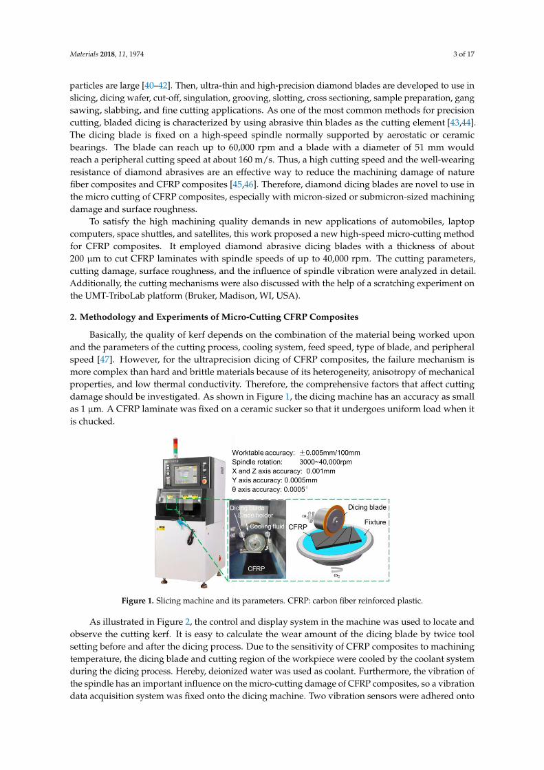
Basically, the quality of kerf depends on the combination of the material being worked uponand the parameters of the cutting process, cooling system, feed speed, type of blade, and peripheralspeed [47]. However, for the ultraprecision dicing of CFRP composites, the failure mechanism ismore complex than hard and brittle materials because of its heterogeneity, anisotropy of mechanicalproperties, and low thermal conductivity. Therefore, the comprehensive factors that affect cuttingdamage should be investigated. As shown in Figure 1, the dicing machine has an accuracy as smallas 1 µm. A CFRP laminate was fixed on a ceramic sucker so that it undergoes uniform load when itis chucked.
Materials 2018, 11, x FOR PEER REVIEW 3 of 17
in slicing, dicing wafer, cut-off, singulation, grooving, slotting, cross sectioning, sample preparation,
gang sawing, slabbing, and fine cutting applications. As one of the most common methods for
precision cutting, bladed dicing is characterized by using abrasive thin blades as the cutting element
[43,44]. The dicing blade is fixed on a high-speed spindle normally supported by aerostatic or ceramic
bearings. The blade can reach up to 60,000 rpm and a blade with a diameter of 51 mm would reach a
peripheral cutting speed at about 160 m/s. Thus, a high cutting speed and the well-wearing resistance
of diamond abrasives are an effective way to reduce the machining damage of nature fiber composites
and CFRP composites [45,46]. Therefore, diamond dicing blades are novel to use in the micro cutting
of CFRP composites, especially with micron-sized or submicron-sized machining damage and
surface roughness.
To satisfy the high machining quality demands in new applications of automobiles, laptop
computers, space shuttles, and satellites, this work proposed a new high-speed micro-cutting method
for CFRP composites. It employed diamond abrasive dicing blades with a thickness of about 200 μm
to cut CFRP laminates with spindle speeds of up to 40,000 rpm. The cutting parameters, cutting
damage, surface roughness, and the influence of spindle vibration were analyzed in detail.
Additionally, the cutting mechanisms were also discussed with the help of a scratching experiment
on the UMT-TriboLab platform (Bruker, Madison, United States).
2. Methodology and Experiments of Micro-Cutting CFRP Composites
Basically, the quality of kerf depends on the combination of the material being worked upon and
the parameters of the cutting process, cooling system, feed speed, type of blade, and peripheral speed
[47]. However, for the ultraprecision dicing of CFRP composites, the failure mechanism is more
complex than hard and brittle materials because of its heterogeneity, anisotropy of mechanical
properties, and low thermal conductivity. Therefore, the comprehensive factors that affect cutting
damage should be investigated. As shown in Figure 1, the dicing machine has an accuracy as small
as 1 μm. A CFRP laminate was fixed on a ceramic sucker so that it undergoes uniform load when it
is chucked.
Figure 1. Slicing machine and its parameters. CFRP: carbon fiber reinforced plastic. Figure 1. Slicing machine and its parameters. CFRP: carbon fiber reinforced plastic.
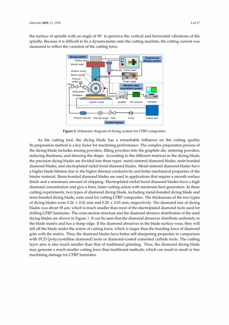
As illustrated in Figure 2, the control and display system in the machine was used to locate andobserve the cutting kerf. It is easy to calculate the wear amount of the dicing blade by twice toolsetting before and after the dicing process. Due to the sensitivity of CFRP composites to machiningtemperature, the dicing blade and cutting region of the workpiece were cooled by the coolant systemduring the dicing process. Hereby, deionized water was used as coolant. Furthermore, the vibration ofthe spindle has an important influence on the micro-cutting damage of CFRP composites, so a vibrationdata acquisition system was fixed onto the dicing machine. Two vibration sensors were adhered onto
Materials 2018, 11, 1974 4 of 17
the surface of spindle with an angle of 90◦ to perceive the vertical and horizontal vibrations of thespindle. Because it is difficult to fix a dynamometer onto the cutting machine, the cutting current wasmeasured to reflect the variation of the cutting force.Materials 2018, 11, x FOR PEER REVIEW 4 of 17
Figure 2. Schematic diagram of dicing system for CFRP composites.
As illustrated in Figure 2, the control and display system in the machine was used to locate and
observe the cutting kerf. It is easy to calculate the wear amount of the dicing blade by twice tool
setting before and after the dicing process. Due to the sensitivity of CFRP composites to machining
temperature, the dicing blade and cutting region of the workpiece were cooled by the coolant system
during the dicing process. Hereby, deionized water was used as coolant. Furthermore, the vibration
of the spindle has an important influence on the micro-cutting damage of CFRP composites, so a
vibration data acquisition system was fixed onto the dicing machine. Two vibration sensors were
adhered onto the surface of spindle with an angle of 90° to perceive the vertical and horizontal
vibrations of the spindle. Because it is difficult to fix a dynamometer onto the cutting machine, the
cutting current was measured to reflect the variation of the cutting force.
As the cutting tool, the dicing blade has a remarkable influence on the cutting quality. Its
preparation method is a key factor for machining performance. The complex preparation process of
the dicing blade includes mixing powders, filling powders into the graphite die, sintering powders,
reducing thickness, and dressing the shape. According to the different matrices in the dicing blade,
the precision dicing blades are divided into three types: metal-sintered diamond blades, resin-bonded
diamond blades, and electroplated nickel bond diamond blades. Metal-sintered diamond blades have
a higher blade lifetime due to the higher thermal conductivity and better mechanical properties of
the binder material. Resin-bonded diamond blades are used in applications that require a smooth
surface finish and a minimum amount of chipping. Electroplated nickel bond diamond blades have
a high diamond concentration and give a freer, faster cutting action with minimum heat generation.
In these cutting experiments, two types of diamond dicing blade, including metal-bonded dicing
blade and resin-bonded dicing blade, were used for cutting CFRP composites. The thicknesses of the
two types of dicing blades were 0.26 ± 0.01 mm and 0.20 ± 0.01 mm, respectively. The diamond size
of dicing blades was about 38 μm, which is much smaller than most of the electroplated diamond
tools used for drilling CFRP laminates. The cross-section structure and the diamond abrasive
distribution of the used dicing blades are shown in Figure 3. It can be seen that the diamond abrasives
distribute uniformly in the blade matrix and has a sharp edge. If the diamond abrasives in the blade
surface wear, they will fall off the blade under the action of cutting force, which is larger than the
bonding force of diamond grits with the matrix. Thus, the diamond blades have better self-
sharpening properties in comparison with PCD (polycrystalline diamond) tools or diamond-coated
cemented carbide tools. The cutting layer area is also much smaller than that of traditional grinding.
Thus, the diamond dicing blade may generate a much smaller cutting force than traditional methods,
which can result in small or free machining damage for CFRP laminates.
Figure 2. Schematic diagram of dicing system for CFRP composites.
As the cutting tool, the dicing blade has a remarkable influence on the cutting quality.Its preparation method is a key factor for machining performance. The complex preparation process ofthe dicing blade includes mixing powders, filling powders into the graphite die, sintering powders,reducing thickness, and dressing the shape. According to the different matrices in the dicing blade,the precision dicing blades are divided into three types: metal-sintered diamond blades, resin-bondeddiamond blades, and electroplated nickel bond diamond blades. Metal-sintered diamond blades havea higher blade lifetime due to the higher thermal conductivity and better mechanical properties of thebinder material. Resin-bonded diamond blades are used in applications that require a smooth surfacefinish and a minimum amount of chipping. Electroplated nickel bond diamond blades have a highdiamond concentration and give a freer, faster cutting action with minimum heat generation. In thesecutting experiments, two types of diamond dicing blade, including metal-bonded dicing blade andresin-bonded dicing blade, were used for cutting CFRP composites. The thicknesses of the two typesof dicing blades were 0.26 ± 0.01 mm and 0.20 ± 0.01 mm, respectively. The diamond size of dicingblades was about 38 µm, which is much smaller than most of the electroplated diamond tools used fordrilling CFRP laminates. The cross-section structure and the diamond abrasive distribution of the useddicing blades are shown in Figure 3. It can be seen that the diamond abrasives distribute uniformly inthe blade matrix and has a sharp edge. If the diamond abrasives in the blade surface wear, they willfall off the blade under the action of cutting force, which is larger than the bonding force of diamondgrits with the matrix. Thus, the diamond blades have better self-sharpening properties in comparisonwith PCD (polycrystalline diamond) tools or diamond-coated cemented carbide tools. The cuttinglayer area is also much smaller than that of traditional grinding. Thus, the diamond dicing blademay generate a much smaller cutting force than traditional methods, which can result in small or freemachining damage for CFRP laminates.

Materials 2018, 11, 1974 5 of 17Materials 2018, 11, x FOR PEER REVIEW 5 of 17
Figure 3. Structure of dicing blade and schematic diagram of cutting process.
In order to demonstrate the influence of the cutting parameters and fiber orientations on cutting
quality, the cutting experiments with different fiber orientations and cutting speeds were conducted
on the dicing machine (Heyan Technology, Shenyang, China) as illustrated in Figure 4. The rotational
speed of the spindle varied from 1000 to 28,000 rpm, in correspondence with the cutting speed from
3 to 85 m/s. The feed speed and cutting depth were 2~4 mm/s and 0.3~0.6 mm, respectively. It can be
observed that the cutting speed is obviously larger than that of most reported machining methods
for CFRP composites. The specimens used for cutting in these experiments were unidirectional T300
CFRP laminates (Shenyang Aircraft Corporation, Shenyang, China). After the cutting process, the
sliced sections of CFRP laminates were observed with an optical microscope (Shanghai Optical
Instrument Co., LTD., Shanghai, China) and SEM (Hitachi High-Technologies Corporation, Tokyo,
Japan) to characterize the dicing damage in different dicing conditions.
Figure 4. Schematic diagram of cutting direction and cutting parameters.
3. Results, Analysis, and Discussion
3.1. Influence of Different Cutting Speeds on Cutting Quality
Just like other nature fiber composites with heterogeneous and anisotropic properties, the
cutting quality of CFRP composites is also very sensitive to the cutting speed. In low cutting speeds,
the fibers embedded in the matrix are easy to bend so as to cause large machining damage, such as
delamination and debonding [46]. High machining speeds over 40 m/s can generate good surface
quality for wood and other fiber reinforced composites [48]. In this study, the cutting current of the
spindle and surface roughness are observed to characterize the influence of cutting speed. Many
studies on the relation between the cutting force and the motor current [49] proved that the change
of spindle motor current value reflects the cutting force well, and cutting force obtained by measuring
the spindle motor current is reasonable and feasible. Due to the limited working space in the dicing
machine, it is difficult to place a dynamometer onto the worktable to detect the cutting force. Thus,
in this experiment, the cutting current obtained from the spindle motor was employed to study the
change of cutting force with different cutting conditions. As illustrated in Figure 5, the cutting current
Figure 3. Structure of dicing blade and schematic diagram of cutting process.
In order to demonstrate the influence of the cutting parameters and fiber orientations on cuttingquality, the cutting experiments with different fiber orientations and cutting speeds were conductedon the dicing machine (Heyan Technology, Shenyang, China) as illustrated in Figure 4. The rotationalspeed of the spindle varied from 1000 to 28,000 rpm, in correspondence with the cutting speed from 3to 85 m/s. The feed speed and cutting depth were 2~4 mm/s and 0.3~0.6 mm, respectively. It can beobserved that the cutting speed is obviously larger than that of most reported machining methods forCFRP composites. The specimens used for cutting in these experiments were unidirectional T300 CFRPlaminates (Shenyang Aircraft Corporation, Shenyang, China). After the cutting process, the slicedsections of CFRP laminates were observed with an optical microscope (Shanghai Optical InstrumentCo., LTD., Shanghai, China) and scanning electron microscope (SEM, Hitachi High-TechnologiesCorporation, Tokyo, Japan) to characterize the dicing damage in different dicing conditions.
Materials 2018, 11, x FOR PEER REVIEW 5 of 17
Figure 3. Structure of dicing blade and schematic diagram of cutting process.
In order to demonstrate the influence of the cutting parameters and fiber orientations on cutting
quality, the cutting experiments with different fiber orientations and cutting speeds were conducted
on the dicing machine (Heyan Technology, Shenyang, China) as illustrated in Figure 4. The rotational
speed of the spindle varied from 1000 to 28,000 rpm, in correspondence with the cutting speed from
3 to 85 m/s. The feed speed and cutting depth were 2~4 mm/s and 0.3~0.6 mm, respectively. It can be
observed that the cutting speed is obviously larger than that of most reported machining methods
for CFRP composites. The specimens used for cutting in these experiments were unidirectional T300
CFRP laminates (Shenyang Aircraft Corporation, Shenyang, China). After the cutting process, the
sliced sections of CFRP laminates were observed with an optical microscope (Shanghai Optical
Instrument Co., LTD., Shanghai, China) and SEM (Hitachi High-Technologies Corporation, Tokyo,
Japan) to characterize the dicing damage in different dicing conditions.
Figure 4. Schematic diagram of cutting direction and cutting parameters.
3. Results, Analysis, and Discussion
3.1. Influence of Different Cutting Speeds on Cutting Quality
Just like other nature fiber composites with heterogeneous and anisotropic properties, the
cutting quality of CFRP composites is also very sensitive to the cutting speed. In low cutting speeds,
the fibers embedded in the matrix are easy to bend so as to cause large machining damage, such as
delamination and debonding [46]. High machining speeds over 40 m/s can generate good surface
quality for wood and other fiber reinforced composites [48]. In this study, the cutting current of the
spindle and surface roughness are observed to characterize the influence of cutting speed. Many
studies on the relation between the cutting force and the motor current [49] proved that the change
of spindle motor current value reflects the cutting force well, and cutting force obtained by measuring
the spindle motor current is reasonable and feasible. Due to the limited working space in the dicing
machine, it is difficult to place a dynamometer onto the worktable to detect the cutting force. Thus,
in this experiment, the cutting current obtained from the spindle motor was employed to study the
change of cutting force with different cutting conditions. As illustrated in Figure 5, the cutting current
Figure 4. Schematic diagram of cutting direction and cutting parameters.
3. Results, Analysis, and Discussion
3.1. Influence of Different Cutting Speeds on Cutting Quality
Just like other nature fiber composites with heterogeneous and anisotropic properties, the cuttingquality of CFRP composites is also very sensitive to the cutting speed. In low cutting speeds, the fibersembedded in the matrix are easy to bend so as to cause large machining damage, such as delaminationand debonding [46]. High machining speeds over 40 m/s can generate good surface quality for woodand other fiber reinforced composites [48]. In this study, the cutting current of the spindle and surfaceroughness are observed to characterize the influence of cutting speed. Many studies on the relationbetween the cutting force and the motor current [49] proved that the change of spindle motor currentvalue reflects the cutting force well, and cutting force obtained by measuring the spindle motor currentis reasonable and feasible. Due to the limited working space in the dicing machine, it is difficultto place a dynamometer onto the worktable to detect the cutting force. Thus, in this experiment,the cutting current obtained from the spindle motor was employed to study the change of cuttingforce with different cutting conditions. As illustrated in Figure 5, the cutting current of the spindle

Materials 2018, 11, 1974 6 of 17
motor first increased with the rotational speed of the spindle and then decreased under the conditionof no-load. The cutting current under the cutting condition has a similar trend of that of no-load.The difference is that there is an obvious increase when the spindle rotational speed changes from25,000 to 28,000 rpm under the cutting condition. It indicates that under rotational speeds higher than25,000 rpm, the cutting resistance increases enormously. High cutting current in the rotational speed of4000 rpm attributes to the self-excited chatter vibrations of the spindle. Under the condition of lowrotational speeds, the cutting layer area is larger than that of high rotational speeds. Cutting force andcutting current therefore increases in low rotational speeds.
Materials 2018, 11, x FOR PEER REVIEW 6 of 17
of the spindle motor first increased with the rotational speed of the spindle and then decreased under
the condition of no-load. The cutting current under the cutting condition has a similar trend of that
of no-load. The difference is that there is an obvious increase when the spindle rotational speed
changes from 25,000 to 28,000 rpm under the cutting condition. It indicates that under rotational
speeds higher than 25,000 rpm, the cutting resistance increases enormously. High cutting current in
the rotational speed of 4000 rpm attributes to the self-excited chatter vibrations of the spindle. Under
the condition of low rotational speeds, the cutting layer area is larger than that of high rotational
speeds. Cutting force and cutting current therefore increases in low rotational speeds.
1.55
1.60
1.65
1.70
1.75
1.80
1.85
1.90
28,00025,000
22,00019,000
16,00013,000
10,0007000
4000
Cutt
ing c
urr
ent
(A)
Spindle rotational speed (rpm)
Conditions
No-load
Feed speed Vf = 2mm/s
Cutting depth ap = 0.3mm
Coolant flow VL= 2.5L/min
Dicing with metal bonded diamond blade
1000
Figure 5. Maximum cutting current varying with spindle rotational speed.
As presented in Figure 6, the surface roughness of machined CFRP laminates appears to have
the same tendency as the cutting current, which illustrates that there is a significant correlation
between cutting current and surface roughness. According to previous studies, the cutting current
can reflect the cutting force reasonably. Thus, small cutting forces will generate lower surface
roughness. It can conclude that CFRP laminates present the best cutting quality at the rotationl speed
of 25,000 rpm where the spindle motor runs steadily. Too high rotational speeds of the spindle are
not beneficial in improving the dicing quality of CFRP laminates. Meanwhile, the deformation of the
dicing blade and vibration of the spindle in low rotational speeds increases the surface roughness of
CFRP laminates.
0.0
0.1
0.2
0.3
0.4
0.5
Surf
ace r
ough
ness R
a (m
)
Spindle rotational speed n (rpm)
Dicing with metal bonded diamond blade
Feed speed Vf = 2mm/s
Cutting depth ap = 0.3mm
Coolant flow VL = 2.5L/min
28,00025,000
22,00019,000
16,00013,000
10,0007000
40001000
Figure 6. Surface roughness varying with spindle rotational speed.
Because the thickness of the dicing blade is very thin in comparison with the traditional grinding
wheel, it is easy to deform or even break under the cutting force. In order to prevent it breaking,
increasing the rotational speed is an effective method to shift the dynamic stiffness of the dicing blade.
Figure 5. Maximum cutting current varying with spindle rotational speed.
As presented in Figure 6, the surface roughness of machined CFRP laminates appears to have thesame tendency as the cutting current, which illustrates that there is a significant correlation betweencutting current and surface roughness. According to previous studies, the cutting current can reflectthe cutting force reasonably. Thus, small cutting forces will generate lower surface roughness. It canconclude that CFRP laminates present the best cutting quality at the rotationl speed of 25,000 rpmwhere the spindle motor runs steadily. Too high rotational speeds of the spindle are not beneficial inimproving the dicing quality of CFRP laminates. Meanwhile, the deformation of the dicing blade andvibration of the spindle in low rotational speeds increases the surface roughness of CFRP laminates.
Materials 2018, 11, x FOR PEER REVIEW 6 of 17
of the spindle motor first increased with the rotational speed of the spindle and then decreased under
the condition of no-load. The cutting current under the cutting condition has a similar trend of that
of no-load. The difference is that there is an obvious increase when the spindle rotational speed
changes from 25,000 to 28,000 rpm under the cutting condition. It indicates that under rotational
speeds higher than 25,000 rpm, the cutting resistance increases enormously. High cutting current in
the rotational speed of 4000 rpm attributes to the self-excited chatter vibrations of the spindle. Under
the condition of low rotational speeds, the cutting layer area is larger than that of high rotational
speeds. Cutting force and cutting current therefore increases in low rotational speeds.
1.55
1.60
1.65
1.70
1.75
1.80
1.85
1.90
28,00025,000
22,00019,000
16,00013,000
10,0007000
4000
Cutt
ing c
urr
ent
(A)
Spindle rotational speed (rpm)
Conditions
No-load
Feed speed Vf = 2mm/s
Cutting depth ap = 0.3mm
Coolant flow VL= 2.5L/min
Dicing with metal bonded diamond blade
1000
Figure 5. Maximum cutting current varying with spindle rotational speed.
As presented in Figure 6, the surface roughness of machined CFRP laminates appears to have
the same tendency as the cutting current, which illustrates that there is a significant correlation
between cutting current and surface roughness. According to previous studies, the cutting current
can reflect the cutting force reasonably. Thus, small cutting forces will generate lower surface
roughness. It can conclude that CFRP laminates present the best cutting quality at the rotationl speed
of 25,000 rpm where the spindle motor runs steadily. Too high rotational speeds of the spindle are
not beneficial in improving the dicing quality of CFRP laminates. Meanwhile, the deformation of the
dicing blade and vibration of the spindle in low rotational speeds increases the surface roughness of
CFRP laminates.
0.0
0.1
0.2
0.3
0.4
0.5
Su
rfa
ce r
oug
hness R
a (m
)
Spindle rotational speed n (rpm)
Dicing with metal bonded diamond blade
Feed speed Vf = 2mm/s
Cutting depth ap = 0.3mm
Coolant flow VL = 2.5L/min
28,00025,000
22,00019,000
16,00013,000
10,0007000
40001000
Figure 6. Surface roughness varying with spindle rotational speed.
Because the thickness of the dicing blade is very thin in comparison with the traditional grinding
wheel, it is easy to deform or even break under the cutting force. In order to prevent it breaking,
increasing the rotational speed is an effective method to shift the dynamic stiffness of the dicing blade.
Figure 6. Surface roughness varying with spindle rotational speed.
Because the thickness of the dicing blade is very thin in comparison with the traditional grindingwheel, it is easy to deform or even break under the cutting force. In order to prevent it breaking,

Materials 2018, 11, 1974 7 of 17
increasing the rotational speed is an effective method to shift the dynamic stiffness of the dicingblade. Therefore, the thin dicing blade does not deform like paper during the cutting process. If thedicing blade is regarded as a hollow disk with a rectangular section, according to the theory of solidmechanics, the maximum stress and displacement of the dicing blade can be calculated with thefollowing equations.
σr =3 + µ
8ρω2
(r2
0 + r2i − r2 −
r20r2
ir2
), (1)
στ =3 + µ
8ρω2
(r2
0 + r2i −
1 + 3µ
1− 3µr2 +
r20r2
ir2
), (2)
u =1− µ2
8Eσω2
[3 + µ
1 + µ
(r2
0 + r2i
)r +
(3 + µ
1− µ
)r2
0r2i
r2 − r3
], (3)
where, r =√
r0ri, σr, στ and u are radial stress, circumferential stress, and displacement, respectively.µ, ρ, and E are the Poisson’s ratio, density, and elasticity modulus of the dicing blade, respectively.Because the diamond abrasive dicing blade is made of typical heterogenetic materials, it is difficult tocalculate the above parameters accurately. Thus, in this study the average values of Poisson’s ratio,density, and elasticity modulus are estimated as 0.22, 5.1 × 10³ kg/m3, and 128 GPa in considerationof the proportion of diamond abrasive and matrix.
Figure 7 shows the simulation results of circumferential stress, radial stress, and displacementof the dicing blade. With the increase of rotational speed, circumferential stress and displacement ofdicing blade increase remarkably. High circumferential stress spreads the dicing blade to ensure thatthe dicing blade has enough rigidity, although it is so thin like paper. It effectively prevents the dicingblade from large deformations under the interactions of the cutting force. That is the reason why thecutting quality of CFRP composites is better at high rotational speeds. Also, it may be a preconditionfor micro-cutting CFRP laminates with an ultra-thin dicing blade.
Materials 2018, 11, x FOR PEER REVIEW 7 of 17
Therefore, the thin dicing blade does not deform like paper during the cutting process. If the dicing
blade is regarded as a hollow disk with a rectangular section, according to the theory of solid
mechanics, the maximum stress and displacement of the dicing blade can be calculated with the
following equations.
2 2
2 2 2 2 0
0 2
3
8
i
r i
r rr r r
r
, (1)
2 2
2 2 2 2 0
0 2
3 1 3
8 1 3
i
i
r rr r r
r
, (2)
2 22
2 2 2 30
0 2
1 3 3
8 1 1
i
i
r ru r r r r
E r
, (3)
where, 0 ir r r , σr, στ and u are radial stress, circumferential stress, and displacement, respectively.
μ, ρ, and E are the Poisson's ratio, density, and elasticity modulus of the dicing blade, respectively.
Because the diamond abrasive dicing blade is made of typical heterogenetic materials, it is difficult
to calculate the above parameters accurately. Thus, in this study the average values of Poisson’s ratio,
density, and elasticity modulus are estimated as 0.22, 5.1 × 10³ kg/m3, and 128 GPa in consideration
of the proportion of diamond abrasive and matrix.
Figure 7 shows the simulation results of circumferential stress, radial stress, and displacement
of the dicing blade. With the increase of rotational speed, circumferential stress and displacement of
dicing blade increase remarkably. High circumferential stress spreads the dicing blade to ensure that
the dicing blade has enough rigidity, although it is so thin like paper. It effectively prevents the dicing
blade from large deformations under the interactions of the cutting force. That is the reason why the
cutting quality of CFRP composites is better at high rotational speeds. Also, it may be a precondition
for micro-cutting CFRP laminates with an ultra-thin dicing blade.
0 5,000 10,000 15,000 20,000 25,00030,000 35,000
0
5
10
15
20
25
30
35
40
45
50
55
60
Dis
pla
ce
me
nt
of
dic
ing
bla
de
(m
)
Ma
xim
um
str
ess o
f d
icin
g b
lad
e (
MP
a)
Rotational Speed n (r/min)
Circumferential stress
Radial stress
Circumferential stress
distribution
Radial stress
distribution
5000
0.000
0.005
0.010
0.015
0.020 Displacement
Displacement
disribution
Figure 7. Maximum stress and displacement of the dicing blade with different rotational speed.
3.2. Influence of Spindle Vibration on Cutting Quality of CFRP Laminates
The main mechanisms generating excessive cutting tool vibration can be classified into three
types: regenerative, mode coupling, and velocity-dependent [50]. Velocity-dependent mainly
originates from the self-excited chatter vibrations of spindle. When the rotational speed is about 4000
rpm, the resonance of the spindle drives the large vibration of the cutting tool, which therefore results
in large cutting surface roughness. The regenerative vibration has a simple relationship between the
cutting force coefficient, dynamic stiffness of the structure, spindle speed, and depth of cut [51]. The
vibration stability has been attributed to either the change in the direction of cutting speed or the
cutting force between the cutting tool and the finished workpiece. During the cutting process with
Figure 7. Maximum stress and displacement of the dicing blade with different rotational speed.
3.2. Influence of Spindle Vibration on Cutting Quality of CFRP Laminates
The main mechanisms generating excessive cutting tool vibration can be classified into three types:regenerative, mode coupling, and velocity-dependent [50]. Velocity-dependent mainly originatesfrom the self-excited chatter vibrations of spindle. When the rotational speed is about 4000 rpm,the resonance of the spindle drives the large vibration of the cutting tool, which therefore resultsin large cutting surface roughness. The regenerative vibration has a simple relationship betweenthe cutting force coefficient, dynamic stiffness of the structure, spindle speed, and depth of cut [51].

Materials 2018, 11, 1974 8 of 17
The vibration stability has been attributed to either the change in the direction of cutting speed orthe cutting force between the cutting tool and the finished workpiece. During the cutting processwith the dicing blade, the cutting speed is located in the direction normal to the axis of the spindle.Furthermore, the cutting force can be divided into two component forces in vertical and horizontaldirections. Thus, the vibrations in the vertical and horizontal directions are obvious. When therotational speed increases to 28,000 rpm from 25,000 rpm, the vibration in the horizontal direction has asignificant increase, as shown in Figure 8. It demonstrates that the large surface roughness and cuttingcurrent is mainly caused by the vibration in the horizontal direction. The vibration of the spindle inthe vertical direction is small due to the weight of the spindle and the load shift in the stiffness of thespindle in the vertical direction. Besides, the change of the cutting force in the horizontal direction dueto the heterogeneity between the fiber and resin matrix can also be attributed to the large vibration.Other cutting parameters, such as feed speed and cutting depth, have a small effect on the vibrationamplitude of the spindle. As shown in Figure 8c, there is a slight increase of vibration amplitude in thevertical direction when the cutting depth changes from 0.2 to 0.8 mm, while the vibration amplitude ofthe spindle in the horizontal direction keeps a steady change varying with the cutting parameters.
Materials 2018, 11, x FOR PEER REVIEW 8 of 17
the dicing blade, the cutting speed is located in the direction normal to the axis of the spindle.
Furthermore, the cutting force can be divided into two component forces in vertical and horizontal
directions. Thus, the vibrations in the vertical and horizontal directions are obvious. When the
rotational speed increases to 28,000 rpm from 25,000 rpm, the vibration in the horizontal direction
has a significant increase, as shown in Figure 8. It demonstrates that the large surface roughness and
cutting current is mainly caused by the vibration in the horizontal direction. The vibration of the
spindle in the vertical direction is small due to the weight of the spindle and the load shift in the
stiffness of the spindle in the vertical direction. Besides, the change of the cutting force in the
horizontal direction due to the heterogeneity between the fiber and resin matrix can also be attributed
to the large vibration. Other cutting parameters, such as feed speed and cutting depth, have a small
effect on the vibration amplitude of the spindle. As shown in Figure 8c, there is a slight increase of
vibration amplitude in the vertical direction when the cutting depth changes from 0.2 to 0.8 mm,
while the vibration amplitude of the spindle in the horizontal direction keeps a steady change varying
with the cutting parameters.
15,000 20,000 25,000 30,000
0
5
10
15
20
25
30
Accele
ration
am
plit
ud
e (
m/s
2)
Rotational speed (rpm)
Vertical, conditions
Horizontal, no-load
Vertical, no-load
Horizontal, conditions
2 4 6 8
1.5
2.0
2.5
3.0
3.5
4.0
4.5
5.0
5.5
6.0
Accele
ration
am
plitu
de (
m/s
2)
Feed speed (mm/s)
Vertical, conditions
Horizontal, conditions
0.2 0.4 0.6 0.8
1.5
2.0
2.5
3.0
3.5
4.0
4.5
5.0
5.5
6.0
Accele
ration
am
plit
ud
e (
m/s
2)
Cutting depth (mm)
Vertical, conditions
Horizontal, conditions
(a) Rotational speed (b) Feed speed (c) Cutting depth
Figure 8. Vibration acceleration amplitude varying with cutting parameters in time domain.
Figure 9 illustrates the vibration acceleration spectrum diagram with different conditions in
frequency domain. As can be seen from the figures, the vibration amplitudes under the condition of
cutting are a little larger than the vibration amplitudes under the condition of no-load. It indicates
that the cutting force has a weak effect on the vibration of the spindle because the cutting force
generated by the ultra-thin dicing blade is very small at high rotational speeds. However, it should
be noted that the vibration amplitudes under the rotational speed of 30,000 rpm are apparently more
serious than that of 25,000 rpm. The serious vibration also results in larger surface roughness of CFRP
laminates after cutting with the dicing blade. Moreover, there is no new vibration frequency to create
by comparing cutting conditions with the no-load condition. The vibration during the cutting process
mainly derives from the spindle motor and the dicing machine itself but not the cutting force. The
promotion of a small cutting force generated by the dicing blade to the vibration of the spindle is very
weak, although the vibration plays a remarkable role on the surface roughness of CFRP laminates.
Figure 8. Vibration acceleration amplitude varying with cutting parameters in time domain.
Figure 9 illustrates the vibration acceleration spectrum diagram with different conditions infrequency domain. As can be seen from the figures, the vibration amplitudes under the condition ofcutting are a little larger than the vibration amplitudes under the condition of no-load. It indicates thatthe cutting force has a weak effect on the vibration of the spindle because the cutting force generated bythe ultra-thin dicing blade is very small at high rotational speeds. However, it should be noted that thevibration amplitudes under the rotational speed of 30,000 rpm are apparently more serious than thatof 25,000 rpm. The serious vibration also results in larger surface roughness of CFRP laminates aftercutting with the dicing blade. Moreover, there is no new vibration frequency to create by comparingcutting conditions with the no-load condition. The vibration during the cutting process mainly derivesfrom the spindle motor and the dicing machine itself but not the cutting force. The promotion of asmall cutting force generated by the dicing blade to the vibration of the spindle is very weak, althoughthe vibration plays a remarkable role on the surface roughness of CFRP laminates.

Materials 2018, 11, 1974 9 of 17
Materials 2018, 11, x FOR PEER REVIEW 8 of 17
the dicing blade, the cutting speed is located in the direction normal to the axis of the spindle.
Furthermore, the cutting force can be divided into two component forces in vertical and horizontal
directions. Thus, the vibrations in the vertical and horizontal directions are obvious. When the
rotational speed increases to 28,000 rpm from 25,000 rpm, the vibration in the horizontal direction
has a significant increase, as shown in Figure 8. It demonstrates that the large surface roughness and
cutting current is mainly caused by the vibration in the horizontal direction. The vibration of the
spindle in the vertical direction is small due to the weight of the spindle and the load shift in the
stiffness of the spindle in the vertical direction. Besides, the change of the cutting force in the
horizontal direction due to the heterogeneity between the fiber and resin matrix can also be attributed
to the large vibration. Other cutting parameters, such as feed speed and cutting depth, have a small
effect on the vibration amplitude of the spindle. As shown in Figure 8c, there is a slight increase of
vibration amplitude in the vertical direction when the cutting depth changes from 0.2 to 0.8 mm,
while the vibration amplitude of the spindle in the horizontal direction keeps a steady change varying
with the cutting parameters.
15,000 20,000 25,000 30,000
0
5
10
15
20
25
30
Accele
ration
am
plit
ud
e (
m/s
2)
Rotational speed (rpm)
Vertical, conditions
Horizontal, no-load
Vertical, no-load
Horizontal, conditions
2 4 6 8
1.5
2.0
2.5
3.0
3.5
4.0
4.5
5.0
5.5
6.0
Accele
ration
am
plitu
de (
m/s
2)
Feed speed (mm/s)
Vertical, conditions
Horizontal, conditions
0.2 0.4 0.6 0.8
1.5
2.0
2.5
3.0
3.5
4.0
4.5
5.0
5.5
6.0
Accele
ration
am
plit
ud
e (
m/s
2)
Cutting depth (mm)
Vertical, conditions
Horizontal, conditions
(a) Rotational speed (b) Feed speed (c) Cutting depth
Figure 8. Vibration acceleration amplitude varying with cutting parameters in time domain.
Figure 9 illustrates the vibration acceleration spectrum diagram with different conditions in
frequency domain. As can be seen from the figures, the vibration amplitudes under the condition of
cutting are a little larger than the vibration amplitudes under the condition of no-load. It indicates
that the cutting force has a weak effect on the vibration of the spindle because the cutting force
generated by the ultra-thin dicing blade is very small at high rotational speeds. However, it should
be noted that the vibration amplitudes under the rotational speed of 30,000 rpm are apparently more
serious than that of 25,000 rpm. The serious vibration also results in larger surface roughness of CFRP
laminates after cutting with the dicing blade. Moreover, there is no new vibration frequency to create
by comparing cutting conditions with the no-load condition. The vibration during the cutting process
mainly derives from the spindle motor and the dicing machine itself but not the cutting force. The
promotion of a small cutting force generated by the dicing blade to the vibration of the spindle is very
weak, although the vibration plays a remarkable role on the surface roughness of CFRP laminates.
Materials 2018, 11, x FOR PEER REVIEW 9 of 17
Figure 9. Vibration acceleration spectrum diagram with different conditions in frequency domain. (a)
With a rotational speed of 25,000 rpm and no-load condition; (b) with a rotational speed of 25,000 rpm
and conditions, (c) with a rotational speed of 30,000 rpm and no-load condition; (d) with a rotational
speed of 30,000 rpm and conditions.
3.3. Influence of Fiber Orientations on Dicing Quality
The fiber orientations have remarkable influence on the cutting current and surface quality due
to the outstanding anisotropy of CFRP laminates. Figure 10 shows the maximum cutting current of
the spindle motor when different fiber orientation laminates are cut with the resin-bonded dicing
blade and the metal-bonded dicing blade. It can be noted that the cutting current of the spindle motor
with the metal-bonded dicing blade are overall smaller than that of with the resin-bonded dicing
blade, which is different from the cutting of regular brittle materials, such as glass. When cutting
brittle materials, the cutting force with a resin-bonded blade is usually smaller than the metal-bonded
blade due to the small bonding force of diamond grits with resin matrix. For cutting CFRP composites
in this experiment, the poor thermal conductivity of the resin-bonded blade and the CFRP workpiece
led to the increase in cutting temperature and the softening of the resin, which results in shifting the
cutting force. Therefore, the large cutting force generates a larger cutting current with the resin-
bonded blade and causes more serious wear to the dicing blade. It can be verified by the results of
the cutting experiments. The wear amounts of the resin-bonded blade in the diameter direction is
about 0.17 mm per cutting 10 m, while the wear amounts of the metal-bonded blade is about 0.13 mm
per cutting 10 m.
The cutting currents of the spindle motor present an overall V-shape tendency when the fiber
orientation angle changes from 0° to 180°. The minimum cutting current occurs at the fiber orientation
of 90°. That is to say that cutting along with fiber orientation can generate a maximum cutting current,
and cutting perpendicular to fiber orientation can generate a minimum cutting current. Moreover,
there are two low points at the fiber orientations of about 40° and 140°. All these tendencies are
contrary to most reported results of milling and orthogonal cutting of CFRP composites [19,20].
Usually the cutting force will increase with the fiber orientation as it changes from 0° to 90°. The
differences can be attributed to the different cutting mechanisms between dicing and milling or
orthogonal cutting. During the milling and orthogonal cutting, the feed rate or feed per tooth is far
larger than the diameter of a fiber. Many fibers, together with the resin matrix, are cut down at one
time [52]. It results in the carbon fibers and resin matrix undergoing serious deformation under the
large cutting force generated by the large tool edge radius. However, for dicing CFRP composites
with the diamond dicing blade, the feed rate can be calculated at about 9.6 μm/r. Additionally, there
are more than one thousand diamond grits that participate in the cutting in the circumference of a
dicing blade. Thus, the feed rate per grit is no more than 0.0096 μm, which is far smaller than the
diameter of carbon fiber. With the small cutting depth, the cutting action or material removal only
occurs at the local regions of carbon fiber or resin matrix. It cannot cause large deformation to the
fibers or resin matrix. Thus, the cutting damage is limited in a small region correspondingly and a
fine machined surface is obtained.
Figure 9. Vibration acceleration spectrum diagram with different conditions in frequency domain.(a) With a rotational speed of 25,000 rpm and no-load condition; (b) with a rotational speed of 25,000 rpmand conditions, (c) with a rotational speed of 30,000 rpm and no-load condition; (d) with a rotationalspeed of 30,000 rpm and conditions.
3.3. Influence of Fiber Orientations on Dicing Quality
The fiber orientations have remarkable influence on the cutting current and surface quality due tothe outstanding anisotropy of CFRP laminates. Figure 10 shows the maximum cutting current of thespindle motor when different fiber orientation laminates are cut with the resin-bonded dicing bladeand the metal-bonded dicing blade. It can be noted that the cutting current of the spindle motor withthe metal-bonded dicing blade are overall smaller than that of with the resin-bonded dicing blade,which is different from the cutting of regular brittle materials, such as glass. When cutting brittlematerials, the cutting force with a resin-bonded blade is usually smaller than the metal-bonded bladedue to the small bonding force of diamond grits with resin matrix. For cutting CFRP composites inthis experiment, the poor thermal conductivity of the resin-bonded blade and the CFRP workpieceled to the increase in cutting temperature and the softening of the resin, which results in shifting thecutting force. Therefore, the large cutting force generates a larger cutting current with the resin-bondedblade and causes more serious wear to the dicing blade. It can be verified by the results of the cuttingexperiments. The wear amounts of the resin-bonded blade in the diameter direction is about 0.17 mmper cutting 10 m, while the wear amounts of the metal-bonded blade is about 0.13 mm per cutting 10 m.Materials 2018, 11, x FOR PEER REVIEW 10 of 17
0 20 40 60 80 100 120 140 160 180
1.705
1.710
1.715
1.720
1.725
1.730
1.735
1.740
1.745
1.750
Cu
ttin
g c
urr
en
t (A
)
Fiber orientation angles ()
Resin bonded dicing blade
Metal bonded dicing blade
Cutting speed Vc = 76m/s
Feed speed Vf = 4mm/s
Cutting depth ap = 0.6mm
Coolant flow rate VL = 2.5L/min
Figure 10. Maximum cutting current varying with fiber orientation.
Figure 11 gives the surface roughness of machined CFRP composites varying with the fiber
orientation. It is interesting that the tendency of the surface roughness changing with fiber orientation
is very similar to that of the cutting current. It illustrates that the surface roughness of diced CFRP
composites has a significant correlation with cutting force. When the cutting direction is vertical to
fiber orientation, the surface roughness of machined CFRP composites is smallest, which is about Ra
0.025 μm, better than most reported experimental results with drilling, milling, or grinding methods.
The fiber orientations of 50° and 130° also achieve a relatively better diced surface, while the surface
roughness is worst when the fiber orientation is 0° or 180°. These tendencies are also different from
traditional milling and drilling processes just as is the cutting current of the spindle motor.
Furthermore, the metal-bonded dicing blade generates better surface roughness than the resin-
bonded dicing blade, mainly due to its low cutting force and good thermal conductivity.
0 20 40 60 80 100 120 140 160 1800.00
0.05
0.10
0.15
0.20
0.25
Su
rfa
ce
ro
ug
hn
ess R
a (m
)
Fiber orientation angle ()
Metal bonded dicing blade
Resin bonded dicing blade
Cutting speed Vc = 76m/s
Feed speed Vf = 4mm/s
Cutting depth ap = 0.6mm
Coolant flow rate VL = 2.5L/min
Figure 11. Surface roughness varying with fiber orientation.
In order to address the reason of the above tendency of surface roughness, surface morphologies
of diced CFRP composites with different fiber orientations are investigated, as shown in Figure 12.
As can be seen from the figures, the surface qualities of diced CFRP composites with the metal-
bonded dicing blade are better than that of the resin-bonded dicing blade. According to the
observations of cutting morphologies, one of main reasons causing large surface roughness with the
resin-bonded dicing blade is that there is some molten resin on the machined surface of CFRP
composites. It reflects that the high dicing temperature occurs during this process. Under the high
temperature, a lot of molten resin adheres to the dicing blade and the machined surface, which not
only reduces the cutting performance of the dicing blade, but also increases the machined surface
roughness of CFRP composites and the cutting force. In view of cutting CFRP composites with 0°
fiber orientations as shown in Figure 12a,e, the fibers have been cut off along their axis. The machined
Figure 10. Maximum cutting current varying with fiber orientation.

Materials 2018, 11, 1974 10 of 17
The cutting currents of the spindle motor present an overall V-shape tendency when the fiberorientation angle changes from 0◦ to 180◦. The minimum cutting current occurs at the fiber orientationof 90◦. That is to say that cutting along with fiber orientation can generate a maximum cutting current,and cutting perpendicular to fiber orientation can generate a minimum cutting current. Moreover, thereare two low points at the fiber orientations of about 40◦ and 140◦. All these tendencies are contraryto most reported results of milling and orthogonal cutting of CFRP composites [19,20]. Usually thecutting force will increase with the fiber orientation as it changes from 0◦ to 90◦. The differences canbe attributed to the different cutting mechanisms between dicing and milling or orthogonal cutting.During the milling and orthogonal cutting, the feed rate or feed per tooth is far larger than the diameterof a fiber. Many fibers, together with the resin matrix, are cut down at one time [52]. It results in thecarbon fibers and resin matrix undergoing serious deformation under the large cutting force generatedby the large tool edge radius. However, for dicing CFRP composites with the diamond dicing blade,the feed rate can be calculated at about 9.6 µm/r. Additionally, there are more than one thousanddiamond grits that participate in the cutting in the circumference of a dicing blade. Thus, the feed rateper grit is no more than 0.0096 µm, which is far smaller than the diameter of carbon fiber. With thesmall cutting depth, the cutting action or material removal only occurs at the local regions of carbonfiber or resin matrix. It cannot cause large deformation to the fibers or resin matrix. Thus, the cuttingdamage is limited in a small region correspondingly and a fine machined surface is obtained.
Figure 11 gives the surface roughness of machined CFRP composites varying with the fiberorientation. It is interesting that the tendency of the surface roughness changing with fiber orientationis very similar to that of the cutting current. It illustrates that the surface roughness of diced CFRPcomposites has a significant correlation with cutting force. When the cutting direction is vertical tofiber orientation, the surface roughness of machined CFRP composites is smallest, which is about Ra0.025 µm, better than most reported experimental results with drilling, milling, or grinding methods.The fiber orientations of 50◦ and 130◦ also achieve a relatively better diced surface, while the surfaceroughness is worst when the fiber orientation is 0◦ or 180◦. These tendencies are also different fromtraditional milling and drilling processes just as is the cutting current of the spindle motor. Furthermore,the metal-bonded dicing blade generates better surface roughness than the resin-bonded dicing blade,mainly due to its low cutting force and good thermal conductivity.
Materials 2018, 11, x FOR PEER REVIEW 10 of 17
0 20 40 60 80 100 120 140 160 180
1.705
1.710
1.715
1.720
1.725
1.730
1.735
1.740
1.745
1.750
Cu
ttin
g c
urr
en
t (A
)
Fiber orientation angles ()
Resin bonded dicing blade
Metal bonded dicing blade
Cutting speed Vc = 76m/s
Feed speed Vf = 4mm/s
Cutting depth ap = 0.6mm
Coolant flow rate VL = 2.5L/min
Figure 10. Maximum cutting current varying with fiber orientation.
Figure 11 gives the surface roughness of machined CFRP composites varying with the fiber
orientation. It is interesting that the tendency of the surface roughness changing with fiber orientation
is very similar to that of the cutting current. It illustrates that the surface roughness of diced CFRP
composites has a significant correlation with cutting force. When the cutting direction is vertical to
fiber orientation, the surface roughness of machined CFRP composites is smallest, which is about Ra
0.025 μm, better than most reported experimental results with drilling, milling, or grinding methods.
The fiber orientations of 50° and 130° also achieve a relatively better diced surface, while the surface
roughness is worst when the fiber orientation is 0° or 180°. These tendencies are also different from
traditional milling and drilling processes just as is the cutting current of the spindle motor.
Furthermore, the metal-bonded dicing blade generates better surface roughness than the resin-
bonded dicing blade, mainly due to its low cutting force and good thermal conductivity.
0 20 40 60 80 100 120 140 160 1800.00
0.05
0.10
0.15
0.20
0.25
Su
rfa
ce
ro
ug
hn
ess R
a (m
)
Fiber orientation angle ()
Metal bonded dicing blade
Resin bonded dicing blade
Cutting speed Vc = 76m/s
Feed speed Vf = 4mm/s
Cutting depth ap = 0.6mm
Coolant flow rate VL = 2.5L/min
Figure 11. Surface roughness varying with fiber orientation.
In order to address the reason of the above tendency of surface roughness, surface morphologies
of diced CFRP composites with different fiber orientations are investigated, as shown in Figure 12.
As can be seen from the figures, the surface qualities of diced CFRP composites with the metal-
bonded dicing blade are better than that of the resin-bonded dicing blade. According to the
observations of cutting morphologies, one of main reasons causing large surface roughness with the
resin-bonded dicing blade is that there is some molten resin on the machined surface of CFRP
composites. It reflects that the high dicing temperature occurs during this process. Under the high
temperature, a lot of molten resin adheres to the dicing blade and the machined surface, which not
only reduces the cutting performance of the dicing blade, but also increases the machined surface
roughness of CFRP composites and the cutting force. In view of cutting CFRP composites with 0°
fiber orientations as shown in Figure 12a,e, the fibers have been cut off along their axis. The machined
Figure 11. Surface roughness varying with fiber orientation.
In order to address the reason of the above tendency of surface roughness, surface morphologies ofdiced CFRP composites with different fiber orientations are investigated, as shown in Figure 12. As canbe seen from the figures, the surface qualities of diced CFRP composites with the metal-bonded dicingblade are better than that of the resin-bonded dicing blade. According to the observations of cuttingmorphologies, one of main reasons causing large surface roughness with the resin-bonded dicing bladeis that there is some molten resin on the machined surface of CFRP composites. It reflects that the

Materials 2018, 11, 1974 11 of 17
high dicing temperature occurs during this process. Under the high temperature, a lot of molten resinadheres to the dicing blade and the machined surface, which not only reduces the cutting performanceof the dicing blade, but also increases the machined surface roughness of CFRP composites and thecutting force. In view of cutting CFRP composites with 0◦ fiber orientations as shown in Figure 12a,e,the fibers have been cut off along their axis. The machined surface of the left-half sections presentsvery good quality in a small region. But not all fibers are strictly embedded in the direction parallelto the machining surface. The fibers not well embedded in the resin matrix will debond from thematrix due to the poor bonding strength of half fiber. The left grooves cause a larger measured surfaceroughness than other fiber orientations. When the CFRP composite is sliced at 90◦ fiber orientation,the fibers are cut smoothly due to the well fixation of fibers in the matrix, according to Figure 12c,g.They have not undergone serious deformation under the cutting force, like milling or drilling. Duringthe milling or drilling process, bunches of fibers bend under the cutting force and finally break toform a zigzag or uneven cutting section [22]. Fiber-tensile failure and matrix-compression failure arenormally used to explain the cutting mechanism for these methods [53]. The microtopography of themachined surface of CFRP with the dicing blade shows its cutting mechanisms are different from thatof milling and drilling. Furthermore, as shown in Figure 12b,f,d,h, there are lot of micro fractureson the machined section of CFRP composites when cutting with 40◦ fiber orientation and 130◦ fiberorientation, although the machined surface is very even. Most of these micro fractures are located at aright position of the fiber section when cutting with 40◦ fiber orientation, and at a left position of thefiber section when cutting with 130◦ fiber orientation. All these positions are at the wedge tip of fiberends, and the material strength is poor. It is easy for the materials at the tip of the fiber to break offunder the actions of cutting force and vibration. Thus, the surface roughness cutting at 40◦ or 130◦
fiber orientation is larger than that of 90◦ fiber orientation. Besides the micro fracture, it should benoted that there are slight fiber debondings with the resin matrix when cutting with 40◦ and 130◦ fiberorientations. It means that the fibers bend towards the fiber bundle extrusion. But this debondingbetween fiber and matrix is far weaker than other methods. That is to say that a very smooth machinedsurface can be obtained when the cutting depth is smaller than the diameter of fibers. No seriousmaterial damage, such as delamination, burrs, fiber pull out, are detected, although obtained surfaceroughness is larger than cutting traditional brittle materials.
Materials 2018, 11, x FOR PEER REVIEW 12 of 17
Figure 12. Surface morphologies of CFRP composites after dicing with different fiber orientation.
Figure 13. Schematic diagram of scratching CFRP composites with diamond indenter.
0 30 60 90 120 150 180 210 240 270 300 330 3600
2
4
6
8
10
12
14
16
18
120 indenter, F z = 10N
90 indenter, F z = 10N
120 indenter, F z = 20N 60 indenter, F z = 10N
90 indenter, F z = 20N
Scratching speed: V c' =76mm/s
Water lubrication
Cu
ttin
g F
orc
e (
N)
Fiber orientation angle ()
60 indenter, F z = 20N
Figure 14. Scratching force varying with fiber orientation.
Figure 12. Surface morphologies of CFRP composites after dicing with different fiber orientation.

Materials 2018, 11, 1974 12 of 17
3.4. Scratching CFRP Composites with Diamond Indenter
In order to reveal the cutting mechanism of dicing CFRP composites, the scratching experimentsof CFRP composites with a diamond indenter were conducted on the UMT-TriboLab platform tocompare the machined quality and cutting force with different fiber orientations and indenter angles,as shown in Figure 13. Three indenters with apical angles of 60◦, 90◦, and 120◦ were chosen to reflectthe sharpness of diamond abrasive grits in the dicing blade. The sharpness of diamond indenters waswell kept before the scratching experiment. Figure 14 shows the scratching force changing with thefiber orientations and the scratching load. Under the same load force, the indenter with apical angle of60◦ generates the highest scratching force. The sharp tip allows it to indent into CFRP composites at ahigher depth. More carbon fibers take part in scratching, so the scratching force is largest. The indenterwith apical angle of 120◦ has a blunt point. It is different to indent into the CFRP. In most circumstances,it scratches on the surface of CFRP composites but does not cut the fibers. Thus, the scratching force issmall. Besides, under the large indent force, the carbon fibers often break off instead of being cut off.Moreover, fiber orientations have remarkable impact on the scratching force. As seen from the figure,the scratching force increases with the increase of fiber orientation from 0◦ to 90◦ and then goes downwith the increase of fiber orientation from 90◦ to 120◦. When scratching direction is perpendicularto fiber orientation, the scratching force is largest, which is different from the trend of dicing CFRPcomposites with the diamond blade. It indicates the two cutting actions are of different machiningmechanisms. The scratching mechanism is similar to the milling and drilling of CFRP composites.
Materials 2018, 11, x FOR PEER REVIEW 12 of 17
Figure 12. Surface morphologies of CFRP composites after dicing with different fiber orientation.
Figure 13. Schematic diagram of scratching CFRP composites with diamond indenter.
0 30 60 90 120 150 180 210 240 270 300 330 3600
2
4
6
8
10
12
14
16
18
120 indenter, F z = 10N
90 indenter, F z = 10N
120 indenter, F z = 20N 60 indenter, F z = 10N
90 indenter, F z = 20N
Scratching speed: V c' =76mm/s
Water lubrication
Cutt
ing F
orc
e (
N)
Fiber orientation angle ()
60 indenter, F z = 20N
Figure 14. Scratching force varying with fiber orientation.
Figure 13. Schematic diagram of scratching CFRP composites with diamond indenter.
Materials 2018, 11, x FOR PEER REVIEW 12 of 17
Figure 12. Surface morphologies of CFRP composites after dicing with different fiber orientation.
Figure 13. Schematic diagram of scratching CFRP composites with diamond indenter.
0 30 60 90 120 150 180 210 240 270 300 330 3600
2
4
6
8
10
12
14
16
18
120 indenter, F z = 10N
90 indenter, F z = 10N
120 indenter, F z = 20N 60 indenter, F z = 10N
90 indenter, F z = 20N
Scratching speed: V c' =76mm/s
Water lubrication
Cutt
ing F
orc
e (
N)
Fiber orientation angle ()
60 indenter, F z = 20N
Figure 14. Scratching force varying with fiber orientation. Figure 14. Scratching force varying with fiber orientation.

Materials 2018, 11, 1974 13 of 17
As shown in Figure 15, the comparisons between the morphologies of CFRP composites obtainedwith the dicing method and scratching identify that the dicing method with a diamond blade canprovide much better surface quality of CFRP composites than traditional cutting. During the dicingprocess with a diamond blade, the carbon fibers were even cut along with its axis without breakingthe carbon fibers. Only when the fiber orientation is not parallel to the dicing surface, the fibers willdebond from the matrix under the cutting force of diamond grits. Thus, there are many debondinggrooves left by carbon fibers, which is the main reason why the surface roughness is largest when thedicing direction is parallel to the fiber orientation. When the dicing direction is perpendicular to thefiber orientation as seen in Figure 15b, carbon fibers embedded well in the resin matrix are difficultto deform during the high-speed cutting process. Thus, carbon fibers are cut orderly. The surfaceroughness in this fiber direction is therefore best. In comparison with diamond blade dicing, themorphologies of CFRP composites obtained by the diamond indenter are much poorer, as presentedin Figure 15c,d. Fiber bundles debonding or breaking are the main cutting mechanisms for diamondindenter scratching. This cutting style dominates that the surface roughness of machined CFRPcomposites is larger than the scales of carbon fibers.
Materials 2018, 11, x FOR PEER REVIEW 13 of 17
As shown in Figure 15, the comparisons between the morphologies of CFRP composites
obtained with the dicing method and scratching identify that the dicing method with a diamond
blade can provide much better surface quality of CFRP composites than traditional cutting. During
the dicing process with a diamond blade, the carbon fibers were even cut along with its axis without
breaking the carbon fibers. Only when the fiber orientation is not parallel to the dicing surface, the
fibers will debond from the matrix under the cutting force of diamond grits. Thus, there are many
debonding grooves left by carbon fibers, which is the main reason why the surface roughness is
largest when the dicing direction is parallel to the fiber orientation. When the dicing direction is
perpendicular to the fiber orientation as seen in Figure 15b, carbon fibers embedded well in the resin
matrix are difficult to deform during the high-speed cutting process. Thus, carbon fibers are cut
orderly. The surface roughness in this fiber direction is therefore best. In comparison with diamond
blade dicing, the morphologies of CFRP composites obtained by the diamond indenter are much
poorer, as presented in Figure 15c,d. Fiber bundles debonding or breaking are the main cutting
mechanisms for diamond indenter scratching. This cutting style dominates that the surface
roughness of machined CFRP composites is larger than the scales of carbon fibers.
Figure 15. Morphologies of CFRP composites obtained by different cutting methods.
3.5. Cutting Mechanism of CFRP Composites with Diamond Blade
According to the above analysis, the cutting mechanism of CFRP composites with a dicing blade
can be briefly concluded as illustrated in Figure 16. The cutting depth per diamond grit (about 10 nm)
during the dicing process is much smaller than the diameter of the carbon fiber (about 7 μm). Under
this machining condition, the cutting force is too small to cause the serious deformation or breaking
off of bulk fiber bundles. The cutting force of diamond grits only acts in a small region of carbon fiber
or resin matrix. Thus, serious macro damages, such as delamination, burrs, and fiber pull out, are
prevented from occurring in the dicing method, which is different from traditional machining
methods [54]. As far as fiber orientation is concerned, when the dicing direction is parallel to the fiber
orientation, fibers on the surface of CFRP composites are not embedded in matrix entirely. It is easy
for them to debond from the resin matrix under the scratching action of diamond grits. The residual
debonding grooves are the main reason in causing the increase of surface roughness. When the
cutting direction is perpendicular to the fiber orientation, carbon fibers are fixed well in the resin
matrix. Only the ends of fibers are cut by diamond grits. It is difficult for fibers to deform under the
condition of a very small cutting depth. Thus, the cutting surfaces are very smooth. Under these
Figure 15. Morphologies of CFRP composites obtained by different cutting methods.
3.5. Cutting Mechanism of CFRP Composites with Diamond Blade
According to the above analysis, the cutting mechanism of CFRP composites with a dicing bladecan be briefly concluded as illustrated in Figure 16. The cutting depth per diamond grit (about10 nm) during the dicing process is much smaller than the diameter of the carbon fiber (about 7 µm).Under this machining condition, the cutting force is too small to cause the serious deformation orbreaking off of bulk fiber bundles. The cutting force of diamond grits only acts in a small region ofcarbon fiber or resin matrix. Thus, serious macro damages, such as delamination, burrs, and fiber pullout, are prevented from occurring in the dicing method, which is different from traditional machiningmethods [54]. As far as fiber orientation is concerned, when the dicing direction is parallel to the fiberorientation, fibers on the surface of CFRP composites are not embedded in matrix entirely. It is easyfor them to debond from the resin matrix under the scratching action of diamond grits. The residualdebonding grooves are the main reason in causing the increase of surface roughness. When the cuttingdirection is perpendicular to the fiber orientation, carbon fibers are fixed well in the resin matrix.Only the ends of fibers are cut by diamond grits. It is difficult for fibers to deform under the condition

Materials 2018, 11, 1974 14 of 17
of a very small cutting depth. Thus, the cutting surfaces are very smooth. Under these circumstances,the shrinking of resin after the dicing process is the main cause in increasing the surface roughnessof machined CFRP composites due to the decrease in temperature. When the dicing direction isat an angle of 45◦ or 135◦ to the fiber orientation, the tips of fibers are easy to break off under thecutting force of diamond grits because of poor support. Thus, the surface roughness is larger thanthat of the dicing direction perpendicular to the fiber orientation. According to the study of Bifano,plastic-flow is the predominant material removal mechanism for grinding brittle materials whengrinding infeed rates are controlled as small as several nanometers per grinding wheel revolution [55].Although somewhat brittle, the cross-section surface of carbon fiber finishes similar to those achievedin polishing or lapping, are achieved in this high-speed dicing process due to the plastic-flow materialremoval mechanism.
Materials 2018, 11, x FOR PEER REVIEW 14 of 17
circumstances, the shrinking of resin after the dicing process is the main cause in increasing the
surface roughness of machined CFRP composites due to the decrease in temperature. When the
dicing direction is at an angle of 45° or 135° to the fiber orientation, the tips of fibers are easy to break
off under the cutting force of diamond grits because of poor support. Thus, the surface roughness is
larger than that of the dicing direction perpendicular to the fiber orientation. According to the study
of Bifano, plastic-flow is the predominant material removal mechanism for grinding brittle materials
when grinding infeed rates are controlled as small as several nanometers per grinding wheel
revolution [55]. Although somewhat brittle, the cross-section surface of carbon fiber finishes similar
to those achieved in polishing or lapping, are achieved in this high-speed dicing process due to the
plastic-flow material removal mechanism.
Figure 16. Schematic diagram of dicing mechanism with different fiber orientations.
4. Conclusions
This study presented the benchmarking investigation and analysis of high-speed low-damage
micro-cutting of CFRP composites with diamond abrasive blades, particularly in light of obtaining
nanoscale smooth surfaces of CFRP composites by introducing nanoscale cutting depth of diamond
grits. The paper also presented the dicing mechanism in high-speed micro-cutting of CFRP
composites. The surface morphology of the processed specimens with different rotational speeds and
fiber orientations were further studied to evaluate and validate the mechanism and analysis. The
concluding results are summarized as follows:
(1) Dicing with diamond abrasive blades enables machining CFRP composites with a high
cutting speed of more than 76 m/s (25,000 rpm). The high cutting speed not only remarkably increases
the rigidity of the ultra-thin dicing blade, but also decreases the cutting depth per diamond grit to
below 10 nm. Both result in a fine surface finish of machined CFRP composites. However, the serious
vibration of the spindle in the horizontal direction limits the rotational speed to increase further. Best
machined surface quality occurs at the rotational speed of 25,000 rpm. The surface roughness of
machined CFRP composites have a similar tendency as the cutting current of the machine mainly due
to the spindle vibration having a more important influence on the cutting current than the cutting
force. Thus, it is necessary to reduce the vibration when the rotational speed is more than 25,000 rpm.
(2) The cutting currents of the spindle motor present an overall V-shape tendency when the fiber
orientation angle changes from 0° to 180° due to the mechanical anisotropy of CFRP composites. The
maximum value occurs at the fiber orientation of 0°, while the minimum value occurs at the fiber
orientation of 90°. With the fiber orientation changing from 0° to 90°, the cutting current presents an
overall decrease but a slight increase at about 40°. This tendency is different from most reported
research about the milling and drilling of CFRP composites. It may be attributed to the different
cutting mechanism of the dicing method with drilling and milling methods. The surface roughness
of machined CFRP composites has a similar tendency with the cutting current. When the cutting
direction is perpendicular to the fiber orientation, the machined CFRP composite obtains the best
surface finish at about Ra 0.025 μm, which is lower than most reported results. Furthermore, the
metal-bonded dicing blade achieves smaller surface roughness than the resin-bonded dicing blade
Figure 16. Schematic diagram of dicing mechanism with different fiber orientations.
4. Conclusions
This study presented the benchmarking investigation and analysis of high-speed low-damagemicro-cutting of CFRP composites with diamond abrasive blades, particularly in light of obtainingnanoscale smooth surfaces of CFRP composites by introducing nanoscale cutting depth of diamondgrits. The paper also presented the dicing mechanism in high-speed micro-cutting of CFRP composites.The surface morphology of the processed specimens with different rotational speeds and fiberorientations were further studied to evaluate and validate the mechanism and analysis. The concludingresults are summarized as follows:
(1) Dicing with diamond abrasive blades enables machining CFRP composites with a high cuttingspeed of more than 76 m/s (25,000 rpm). The high cutting speed not only remarkably increasesthe rigidity of the ultra-thin dicing blade, but also decreases the cutting depth per diamond grit tobelow 10 nm. Both result in a fine surface finish of machined CFRP composites. However, the seriousvibration of the spindle in the horizontal direction limits the rotational speed to increase further.Best machined surface quality occurs at the rotational speed of 25,000 rpm. The surface roughnessof machined CFRP composites have a similar tendency as the cutting current of the machine mainlydue to the spindle vibration having a more important influence on the cutting current than the cuttingforce. Thus, it is necessary to reduce the vibration when the rotational speed is more than 25,000 rpm.
(2) The cutting currents of the spindle motor present an overall V-shape tendency when the fiberorientation angle changes from 0◦ to 180◦ due to the mechanical anisotropy of CFRP composites.The maximum value occurs at the fiber orientation of 0◦, while the minimum value occurs at the fiberorientation of 90◦. With the fiber orientation changing from 0◦ to 90◦, the cutting current presentsan overall decrease but a slight increase at about 40◦. This tendency is different from most reportedresearch about the milling and drilling of CFRP composites. It may be attributed to the differentcutting mechanism of the dicing method with drilling and milling methods. The surface roughness ofmachined CFRP composites has a similar tendency with the cutting current. When the cutting directionis perpendicular to the fiber orientation, the machined CFRP composite obtains the best surface finish

Materials 2018, 11, 1974 15 of 17
at about Ra 0.025 µm, which is lower than most reported results. Furthermore, the metal-bondeddicing blade achieves smaller surface roughness than the resin-bonded dicing blade when cutting withall fiber orientations due to its good thermal conductivity and low friction coefficient.
(3) In comparison with scratching CFRP composites with the diamond indenter, the mechanismof high machining quality achieved with the dicing blade is mainly attributed to the nanoscale cuttingdepth of diamond grits. Such a thin cutting layer allows the material removal to only occur at localregions of carbon fiber or resin matrix. The high cutting speed and low cutting force prevent seriousdeformation or breaking off of bulk fiber. The micro breakage and plastic-flow in local regions are themain material removal mechanisms for dicing CFRP composites with diamond abrasive blades. Thus,the surface roughness of machined CFRP composites mainly depends on the styles of micro breakage.When cutting in the direction perpendicular to the fiber orientation, the surface roughness is lowestdue to the well fixation of fibers in resin matrix. However, when cutting in the direction parallel to thefiber orientation, the debonding of fibers causes relative poor machining quality.
Author Contributions: Conceptualization, Z.Y. and J.H.; methodology, Z.Y. and Q.W.; validation, Z.Y., K.C. andP.Z.; formal analysis, J.H. and Q.W.; investigation, Z.Y. and J.H.; resources, Z.Y.; data curation, J. Hu and Q.W.;writing—original draft preparation, Z.Y.; writing—review and editing, K.C. and P.Z.; supervision, K.C.; projectadministration, Z.Y.; funding acquisition, Z.Y.
Funding: This research was funded by the National Science Foundation of China (Grant No. 51305278; GrantNo. 51505074), the Basic Research Foundation of Liaoning Province Universities (Grant No. LFGD2017007),the Natural Science Foundation of Shenyang City (Grant No. F16-205-1-10), the China Postdoctoral ScienceFoundation (Grant No. 2014M551124) and the Program of China Scholarships Council (Grant No.201708210034).
Acknowledgments: The authors would like to thank Shenyang Changpu Superhard Precision Tools Co.LTD for providing the dicing blades and Brunel University London for hosting the academic visit andresearch collaboration.
Conflicts of Interest: The authors declare no potential conflicts of interest with respect to the research. Thefunders had no role in the design of the study; in the collection, analyses, or interpretation of data; in the writingof the manuscript, or in the decision to publish the results.
References
1. Li, H.; Qin, X.; He, G.; Jin, Y.; Sun, D.; Price, M. Investigation of chip formation and fracture toughness inorthogonal cutting of UD-CFRP. Int. J. Adv. Manuf. Technol. 2016, 82, 1079–1088. [CrossRef]
2. Rahmani, H.; Najafi, S.H.M.; Ashori, A. Mechanical performance of epoxy/carbon fiber laminatedcomposites. J. Reinf. Plast. Compos. 2014, 33, 733–740. [CrossRef]
3. Wang, H.Y.; Qin, X.D.; Li, H.; Ren, C.Z. Analysis of cutting forces in helical milling of carbon fiber–reinforcedplastics. Proc. Inst. Mech. Eng. Part B J. Eng. Manuf. 2013, 227, 62–74.
4. Davim, J.P. Machinability of Fibre-Reinforced Plastics; De Gruyter: Berlin, Germany, 2015.5. Cong, W.L.; Feng, Q.; Pei, Z.J.; Deines, T.W.; Treadwell, C. Rotary ultrasonic machining of carbon
fiber-reinforced plastic composites: using cutting fluid vs. cold air as coolant. J. Compos. Mater. 2011,46, 1745–1753. [CrossRef]
6. Karpat, Y.; Polat, N. Mechanistic force modeling for milling of carbon fiber reinforced polymers with doublehelix tools. CIRP Ann.-Manuf. Technol. 2013, 62, 95–98. [CrossRef]
7. Prakash, R.; Krishnaraj, V.; Zitoune, R.; Sheikh-Ahmad, J. High-speed edge trimming of CFRP and onlinemonitoring of performance of router tools using acoustic emission. Materials 2016, 9, 798. [CrossRef][PubMed]
8. Krishnaraj, V.; Prabukarthi, A.; Ramanathan, A.; Elanghovan, N.; Senthil, K.M.; Zitoune, R.; Davim, J.P.Optimization of machining parameters at high speed drilling of carbon fiber reinforced plastic (CFRP)laminates. Compos. Part B Eng. 2012, 43, 1791–1799. [CrossRef]
9. Haddad, M.; Zitoune, R.; Bougherara, H.; Eyma, F.; Castanié, B. Study of trimming damages of CFRPstructures in function of the machining processes and their impact on the mechanical behavior. Compos. PartB Eng. 2014, 57, 136–143. [CrossRef]
10. Caggiano, A. Machining of fibre reinforced plastic composite materials. Materials 2018, 11, 442. [CrossRef][PubMed]

Materials 2018, 11, 1974 16 of 17
11. Li, Z.L.; Zheng, H.Y.; Lim, G.C.; Chu, P.L.; Li, L. Study on UV laser machining quality of carbon fibrereinforced composites. Compos. Part. A Appl. Sci. Manuf. 2010, 41, 1403–1408. [CrossRef]
12. Muhamad Khairussaleh, N.K.; Haron, C.H.C.; Ghani, A.J. Study on wear mechanism of solid carbide cuttingtool in milling CFRP. J. Mater. Res. 2016, 1, 1–7. [CrossRef]
13. Grilo, T.J.; Paulo, R.M.F.; Silva, C.R.M.; Davim, J.P. Experimental delamination analyses of CFRPs usingdifferent drill geometries. Compos. Part B Eng. 2013, 45, 1344–1350. [CrossRef]
14. Madhavan, V.; Lipczynski, G.; Lane, B.; Whitenton, E. Fiber orientation angle effects in machining ofunidirectional CFRP laminated composites. J. Manuf. Process. 2015, 20, 431–442. [CrossRef]
15. Chatelain, J.; Zaghbani, I. A comparison of special helical cutter geometries based on cutting forces for thetrimming of CFRP laminates. Int. J. Mech. 2012, 1, 52–59.
16. Bora, M.O.; Coban, O.; Sinmazcelik, T.; Gunay, V. Effect of fiber orientation on scratch resistance inunidirectional carbon-fiber-reinforced polymer matrix composites. J. Mater. Res. 2010, 29, 1476–1490.[CrossRef]
17. Islam, F.; Ramkumar, J.; Milani, A.S. A simplified damage prediction framework for milling of unidirectionalcarbon fiber-reinforced plastics. Adv. Manuf. Polym. Compos. Sci. 2016, 1, 175–184. [CrossRef]
18. Sorrentino, L.; Turchetta, S.; Bellini, C. A new method to reduce delaminations during drilling of FRPlaminates by feed rate control. Compos. Struct. 2018, 186, 154–164. [CrossRef]
19. Wang, D.Y.; He, X.D.; Xu, Z.H.; Jiao, W.C.; Yang, F.; Jiang, L.; Li, L.; Liu, W.B.; Wang, R.G. Study on damageevaluation and machinability of UD-CFRP for the orthogonal cutting operation using scanning acousticmicroscopy and the finite element method. Materials 2017, 10, 204. [CrossRef] [PubMed]
20. Wang, F.J.; Wang, X.N.; Yang, R.; Gao, H.Q.; Su, Y.L.; Bi, G.J. Research on the carbon fibre-reinforced plastic(CFRP) cutting mechanism using macroscopic and microscopic numerical simulations. J. Reinf. Plast. Compos.2017, 36, 555–562. [CrossRef]
21. Zhang, Y.; Tani, Y. Cutting characteristics of CFRP boards using electroplated diamond wire tools. J. Mech.Eng. Autom. 2017, 7, 335–340. [CrossRef]
22. Chen, T.; Wang, D.Y.; Gao, F.; Liu, X.L. Experimental study on milling CFRP with staggered PCD cutter.Appl. Sci. 2017, 7, 934. [CrossRef]
23. Fernandez-Valdivielso, A.; Lacalle, L.L.D.; Urbikain, G.; Rodriguez, A. Detecting the key geometrical featuresand grades of carbide inserts for the turning of nickel-based alloys concerning surface integrity. Proc. Inst.Mech. Eng. Part C J. Mech. Eng. Sci. 2016, 230, 3725–3742. [CrossRef]
24. Voss, R.; Seeholzer, L.; Kuster, F.; Wegener, K. Cutting process tribometer experiments for evaluation offriction coefficient close to a CFRP machining operation. Procedia CIRP 2017, 66, 204–209. [CrossRef]
25. Bayraktar, S.; Turgut, Y. Investigation of the cutting forces and surface roughness in milling carbon fiberreinforced polymer composite material. Mater. Technol. 2016, 50, 591–600. [CrossRef]
26. Boudelier, A.; Ritou, M.; Garnier, S.; Furet, B. Investigation of CFRP machining with diamond abrasivecutters. J. Compos. Adv. Mater. 2013, 23, 2–14. [CrossRef]
27. Hu, N.S.; Zhang, L.C. Some observations in grinding unidirectional carbon fibre-reinforced plastics. J. Mater.Process. Technol. 2004, 152, 333–338. [CrossRef]
28. Sorrentino, L.; Turchetta, S.; Bellini, C. Analysis of carbon fibre reinforced polymers milling by diamondelectroplated tool. Diam. Relat. Mater. 2017, 76, 184–190. [CrossRef]
29. Wang, H.; Ning, F.D.; Hu, Y.B.; Fernando, P.K.S.C.; Pei, Z.J.; Cong, W.L. Surface grinding of carbonfiber–reinforced plastic composites using rotary ultrasonic machining: Effects of tool variables. Adv. Mech.Eng. 2016, 8, 1–14. [CrossRef]
30. Ning, F.D.; Cong, W.L.; Pei, Z.J.; Treadwell, C. Rotary ultrasonic machining of CFRP: A comparison withgrinding. Ultrasonics 2016, 66, 125–132. [CrossRef] [PubMed]
31. Cong, W.L.; Pei, Z.J.; Deines, T.W.; Liu, D.F.; Treadwell, C. Rotary ultrasonic machining of CFRP/Ti stacksusing variable federate. Compos. Part B Eng. 2013, 52, 303–310. [CrossRef]
32. Uhlmann, E.; Richarz, S.; Sammler, F.; Hufschmied, R. High speed cutting of carbon fibre reinforced plastics.Procedia Manuf. 2016, 6, 113–123. [CrossRef]
33. Ha, S.J.; Kim, K.B.; Yang, J.K.; Cho, M.W. Influence of cutting temperature on carbon fiber-reinforced plasticcomposites in high-speed machining. J. Mech. Sci. Technol. 2017, 31, 1861–1867. [CrossRef]
34. Uhlmann, E.; Sammler, F.; Richarz, S.; Heitmüller, F.; Bilz, M. Machining of carbon fibre reinforced plastics.Procedia CIRP 2014, 24, 19–24. [CrossRef]

Materials 2018, 11, 1974 17 of 17
35. Majumder, H.; Maity, K. Prediction and optimization of surface roughness and micro-hardness using grnnand MOORA-fuzzy-a MCDM approach for nitinol in WEDM. Measurement 2018, 118, 1–13. [CrossRef]
36. Przestacki, D.; Szymanski, P.; Wojciechowski, S. Formation of surface layer in metal matrix compositeA359/20SiCP during laser assisted turning. Compos. Part A Appl. Sci. Manuf. 2016, 91, 370–379. [CrossRef]
37. Leone, C.; Genna, S. Heat affected zone extension in pulsed Nd:YAG laser cutting of CFRP. Compos. Part BEng. 2018, 140, 174–182. [CrossRef]
38. Herzog, D.; Schmidtlehr, M.; Canisius, M.; Oberlander, M.; Tasche, J.P.; Emmelmann, C. Laser cutting ofcarbon fiber reinforced plastic using a 30 kW fiber laser. J. Laser Appl. 2015, 27, S28001. [CrossRef]
39. Dirk, H.; Marten, C.; Matthias, S.L.; Philipp, H.; Christian, D.; Sina, H.; Claus, E.; Malte, V.S. Investigationson the 3D laser cutting of CFRP using a nanosecond pulse fibre laser. Appl. Polym. Compos. 2014, 2, 177–192.
40. Sánchez Egea, A.J.; Martynenko, V.; Martínez Krahmer, D.; López de Lacalle, L.N.; Benítez, A.; Genovese, G.On the cutting performance of segmented diamond blades when dry-cutting concrete. Materials 2018, 11, 264.[CrossRef] [PubMed]
41. Turchetta, S. Cutting force and diamond tool wear in stone machining. Int. J. Adv. Manuf. Technol. 2012, 61,441–448. [CrossRef]
42. Medhat, S.; El-Mahllawy; Ayman, M.K.; Mahmoud, L.A.L.; Abdeen, M.E.N. The feasibility of using marblecutting waste in a sustainable building clay industry. Recycling 2018, 3, 39.
43. Fuegl, M.; Mackh, G.; Meissner, E.; Frey, L. Analytical stress characterization after different chip separationmethods. Microelectron. Reliab. 2014, 54, 1735–1740. [CrossRef]
44. Sullivan, S. Handbook of Silicon Based MEMS Materials and Technologies; Elsevier: Amsterdam, The Netherlands,2010; Chapter 36 Dicing of MEMS Devices; pp. 671–677.
45. Cheng, K.; Huo, D. Micro Cutting: Fundamentals and Applications; John Wiley & Sons: Chichester, UK, 2013.46. Nassar, M.M.A.; Arunachalam, R.; Alzebdeh, K.I. Machinability of natural fiber reinforced composites:
A review. Int. J. Adv. Manuf. Technol. 2017, 88, 2985–3004. [CrossRef]47. Lin, J.W.; Cheng, M.H. Investigation of chipping and wear of silicon wafer dicing. J. Manuf. Process. 2014, 16,
373–378. [CrossRef]48. Blugan, G.; Strehler, C.; Vetterli, M.; Ehrle, B.; Duttlinger, R.; Blösch, P.; Kuebler, J. Performance of lightweight
coated oxide ceramic composites for industrial high speed wood cutting tools: A step closer to market.Ceram. Int. 2017, 43, 8735–8742. [CrossRef]
49. Jeong, Y.H.; Cho, D.W. Estimating cutting force from rotating and stationary feed motor currents on a millingmachine. Int. J. Mach. Tool Manuf. 2002, 42, 1559–1566. [CrossRef]
50. Kim, P.; Seok, J. Bifurcation analyses on the chatter vibrations of a turning process with state-dependentdelay. Nonlinear Dyn. 2012, 69, 891–912. [CrossRef]
51. Eynian, M.; Altintas, Y. Chatter stability of general turning operations with process damping. Manuf. Sci.E-T ASME 2009, 131, 041005. [CrossRef]
52. Wang, C.Y.; Liu, G.Y.; An, Q.L.; Chen, M. Occurrence and formation mechanism of surface cavity defectsduring orthogonal milling of CFRP laminates. Compos. Part B Eng. 2017, 109, 10–22. [CrossRef]
53. Xu, J.Y.; Mansori, M.E.I. Numberical modeling of stacked composite CFRP/Ti machining under differentcutting sequence strategies. Int. J. Precis. Eng. Manuf. 2016, 17, 99–107. [CrossRef]
54. Phapale, K.; Ahire, A.; Singh, R. Experimental characterization and finite element modeling of critical thrustforce in CFRP drilling. Mater. Sci. Technol. 2018, 22, 249–270. [CrossRef]
55. Bifano, T.G. Ductile-regime grinding: A new technology for machining brittle materials. J. Eng. Ind. 1991,113, 184–189. [CrossRef]
© 2018 by the authors. Licensee MDPI, Basel, Switzerland. This article is an open accessarticle distributed under the terms and conditions of the Creative Commons Attribution(CC BY) license (http://creativecommons.org/licenses/by/4.0/).