investigation of techniques for reducing...
TRANSCRIPT

VILNIUS GEDIMINAS TECHNICAL UNIVERSITY
Evaldas STANKEVIČIUS
INVESTIGATION OF TECHNIQUES FOR REDUCING MOBILE COMMUNICATION SYSTEMS HARMFUL OUT-OF-BAND EMISSION
DOCTORAL DISSERTATION
TECHNOLOGICAL SCIENCES, ELECTRICAL AND ELECTRONIC ENGINEERING (01T)
Vilnius 2017
Doctoral dissertation was prepared at Vilnius Gediminas Technical University in 2012–2017.
Supervisor
Prof. Dr Šarūnas PAULIKAS (Vilnius Gediminas Technical University, Electrical and Electronic Engineering – 01T).
The Dissertation Defense Council of Scientific Field of Electrical and Electronic Engineering of Vilnius Gediminas Technical University:
Chairman
Prof. Dr Vytautas URBANAVIČIUS (Vilnius Gediminas Technical University, Electrical and Electronic Engineering – 01T).
Members:
Dr Ali DZIRI (National Conservatory of Arts and Crafts, France, Electrical and Electronic Engineering – 01T), Assoc. Prof. Dr Gytis MYKOLAITIS (State Research Institute Center for Physical Sciences and Technology, Electrical and Electronic Engineering – 01T), Assoc. Prof. Dr Lina NARBUTAITĖ (Kaunas University of Technology, Electrical and Electronic Engineering – 01T), Assoc. Prof. Dr Artūras SERACKIS (Vilnius Gediminas Technical University, Electrical and Electronic Engineering – 01T).
The dissertation will be defended at the public meeting of the Dissertation Defense Council of Electrical and Electronic Engineering in the Senate Hall of Vilnius Gediminas Technical University at 1 p. m. on 10 March 2017.
Address: Saulėtekio al. 11, LT-10223 Vilnius, Lithuania. Tel.: +370 5 274 4956; fax +370 5 270 0112; e-mail: [email protected] A notification on the intend defending of the dissertation was send on 9 February 2017. A copy of the doctoral dissertation is available for review at the VGTU repository http://dspace.vgtu.lt/ and at the Library of Vilnius Gediminas Technical University (Saulėtekio al. 14, LT-10223 Vilnius, Lithuania) and State research institute Center for Physical Sciences and Technology (Savanorių al. 231, LT-02300 Vilnius, Lithuania).
VGTU leidyklos TECHNIKA 2017-008-M mokslo literatūros knyga
ISBN 978-609-476-006-8
© VGTU leidykla TECHNIKA, 2017 © Evaldas Stankevičius, 2017 [email protected]
VILNIAUS GEDIMINO TECHNIKOS UNIVERSITETAS
Evaldas STANKEVIČIUS
MOBILIOJO RYŠIO SISTEMŲ ŽALINGOS ŠALUTINĖS SPINDULIUOTĖS MAŽINIMO BŪDŲ TYRIMAS
DAKTARO DISERTACIJA
TECHNOLOGIJOS MOKSLAI, ELEKTROS IR ELEKTRONIKOS INŽINERIJA (01T)
Vilnius 2017
Disertacija rengta 2012–2017 metais Vilniaus Gedimino technikos universitete.
Vadovas
prof. dr. Šarūnas PAULIKAS (Vilniaus Gedimino technikos universitetas,
elektros ir elektronikos inžinerija – 01T).
Vilniaus Gedimino technikos universiteto Elektros ir elektronikos inzinerijos mokslo
krypties disertacijos gynimo taryba:
Pirmininkas
prof. dr. Vytautas URBANAVIČIUS (Vilniaus Gedimino technikos
universitetas, elektros ir elektronikos inžinerija – 01T).
Nariai:
dr. Ali DZIRI (Nacionalinė menų ir amatų konservatorija, Prancūzija, elektros ir
elektronikos inžinerija – 01T),
doc. dr. Gytis MYKOLAITIS (Valstybinis mokslinių tyrimų institutas Fizinių ir
technologijos mokslų centras, elektros ir elektronikos inžinerija – 01T),
doc. dr. Lina NARBUTAITĖ (Kauno technologijos universitetas, elektros ir
elektronikos inžinerija – 01T),
doc. dr. Artūras SERACKIS (Vilniaus Gedimino technikos universitetas,
elektros ir elektronikos inžinerija – 01T).
Disertacija bus ginama viešame Elektros ir elektronikos inzinerijos mokslo krypties
disertacijos gynimo tarybos posėdyje 2017 m. kovo 10 d. 13 val. Vilniaus Gedimino
technikos universiteto senato posėdžių salėje.
Adresas: Saulėtekio al. 11, LT-10223 Vilnius, Lietuva.
Tel.: (8 5) 274 4956; faksas (8 5) 270 0112; el. paštas [email protected]
Pranešimai apie numatomą ginti disertaciją išsiųsti 2017 m. vasario 9 d.
Disertaciją galima peržiūrėti VGTU talpykloje http://dspace.vgtu.lt/ ir Vilniaus
Gedimino technikos universiteto bibliotekoje (Saulėtekio al. 14, LT-10223 Vilnius,
Lietuva) ir Valstybinio mokslinių tyrimų instituto Fizinių ir technologijos mokslų
centro bibliotekoje (Savanorių pr. 231, LT-02300 Vilnius, Lietuva).

v
Abstract
Electromagnetic compatibility in the newly designated Long-Term Evolution
(LTE) mobile network in the 790–862 MHz frequency band from perspective of
interference management between neighbouring services are analysed in the dis-sertation. Main focal point of this dissertation is on the problems that face LTE
networks based on Orthogonal Frequency-Division Multiplexing (OFDM) due to
the relatively strong side lobes around the active subcarriers in the main commu-nication channel, which introduces interference effects between LTE stations and
other services.
The introductory chapter presents the investigated problem, objects of re-
search, importance of the dissertation, describes research methodology, scientific novelty and the defended statements.
The situation in the 790–862 MHz frequency band is overviewed regarding
most sensitive challenges in the first chapter: LTE stations’ influence on Short-Range Devices (SRD), digital terrestrial TV broadcasting (DVB-T) and aeronau-
tical radio navigation systems (ARNS). The noticeable lack of information is ob-
served regarding SRD and LTE electromagnetic compatibility.
The Filter Bank Multicarrier Transmission technique (FBMC) is proposed as means to minimize adjacent band interference in the 790–862 MHz frequency
band. Main FBMC benefits are presented through comparison with reference case
of OFDM. The key advantage of FBMC technique is derived from its low out-of-band leakage, which guarantees minimum harmful interference level between sta-
tions using adjacent channels.
The harmful interference of LTE mobile stations’ influence on Short-Range Devices operating in the 863–870 MHz frequency band is analysed in the second
chapter. Two analysis methods are used in this study: first applying theoretical
analysis using Minimum Coupling Loss calculations, then statistical Monte-Carlo
in order to verify results obtained in theoretical approach. The third chapter is focused on the experimental analysis to reproduce the
situation that was investigated in theoretical analysis chapter. Verification of the-
oretical analysis by practical measurements confirmed that the LTE user equip-ment (UE) emissions may affect SRD devices and completely or partially disrupt
their communications at distances of up to several meters from LTE UE. The ob-
tained results are summarized and general conclusions are drawn.

vi
Reziumė
Disertacijoje nagrinėjamas elektromagnetinis suderinamumas tarp ketvirtosios
kartos bevielės komunikacijos standarto LTE (angl. Long-Term Evolution) stočių,
veikiančių naujai suformuotoje 790–862 MHz dažnių juostoje ir kitų radijo ryšio sistemų, kurios veikia kaimyninėse dažnių juostose. Pagrindinis dėmesys
skiriamas problemoms, kurios iškilo įdiegus LTE sistemas, veikiančias
ortogonaliosios dažninio tankinimo moduliacijos OFDM (angl. Orthogonal frequency-division multiplexing) pagrindu. Nustatyti pagrindiniai OFDM sistemų
trūkumai – santykinai aukšta LTE sistemų šalutinė spinduliuotė, kuri sukelia
trikdžius radijo ryšio sistemoms kaimyniniuose dažnių ruožuose.
Įvadiniame skyriuje pristatoma disertacijos problema, tyrimo tikslai bei naujumas, aprašoma tyrimų metodologija ir ginamieji teiginiai.
Pirmame skyriuje analizuojami iššūkiai, kurie laukia įdiegus LTE tinklus
790–862 MHz dažnių juostoje: LTE stočių įtaka trumpojo veikimo nuotolio įrenginiams, skaitmeninės antžeminės televizijos tinklams, radijo navigacijos
sistemoms. Aptiktas žymus mokslinių tyrimų, susijusių su LTE sistemų
elektromagnetiniu suderinamumu su trumpojo veikimo nuotolio įrenginiais,
trūkumas. Ištirtas galimas susietųjų filtrų informacijos perdavimo būdo FBMC (angl.
Filter Bank Multicarrier Transmission technique) panaudojimas ir efektyvumas
siekiant išvengti tarpkanalinės interferencijos 790–862 MHz dažnių juostoje. Nustatytas pagrindinis FBMC informacijos perdavimo būdo pranašumas lyginant
su tradicinėmis LTE sistemomis naudojančiomis OFDM: žemesnio lygio šalutinė
spinduliuotė, kuri garantuoja sumažintą LTE trikdžių poveikį kaimyninėms radijo ryšio sistemoms.
Antrame skyriuje atlikta detali teorinė interferencijos atsiradimo tikimybės
analizė naujai formuojamoje 790–862 MHz dažnių juostoje. Panaudoti du
analizės metodai: atliktas minimalių sąveikos nuostolių MCL (angl. Minimum Coupling Loss) vertinimas, tuomet atlikta statistinė Monte-Carlo analizė siekiant
patikrinti gautus rezultatus naudojant minėtą MCL metodą.
Trečiame skyriuje atlikta eksperimentinė interferencijos atsiradimo analizė naujai suformuotoje 790–862 MHz dažnių juostoje siekiant patvirtinti arba
paneigti rezultatus, kurie buvo gauti atliekant teorinę interferencijos atsiradimo
analizę. Eksperimentiniai matavimai parodė, kad priklausomai nuo trumpojo veikimo nuotolio imtuvo priimamo signalo lygio LTE mobiliosios stotys gali
žalingai paveikti arba visiškai užblokuoti trumpojo veikimo nuotolio sistemų
imtuvus, kai atstumas tarp jų yra nuo 1,5 m iki 9 m. Įvertinus teorinės ir
eksperimentinės analizės rezultatus buvo suformuotos bendrosios išvados.

vii
Notations
Symbols
B – channel bandwidth;
C – carrier;
d – separation distance;
f – frequency;
I – interference;
K – symbol overlapping factor;
N – number of sub-carriers;
P – equivalent isotropically radiated power;
RP – received packets ratio;
S – input signal;
T – symbol duration;
γ – path loss exponent.
Abbreviations
3GPP – 3rd Generation Partnership Project;

viii
ARNS – Aeronautical Radio Navigation Service;
C/(I+N) – Carrier to Interference plus Noise Ratio;
C/I – Carrier to Interference Ratio;
CEPT – European Conference of Postal and Telecommunications Administrations;
CRC – Cyclic Redundancy Check;
DCS – Digital Cellular Service;
DVB-T – Digital Video Broadcast Terrestrial;
ECC – Electronic Communications Committee;
EMC – Electromagnetic Compatibility;
FBMC – Filter Bank Multicarrier transmission technique;
FFT – Fast Fourier Transform;
FSL – Free Space Loss;
GSM – Global Standard for Mobile communications;
I/N – Interference to Noise Ratio;
ICI – Inter-Channel Interference;
IFFT – Inverse Fast Fourier Transform;
ISI – Inter-Symbol Interference;
LTE – Long-Term Evolution;
M2M – Machine to Machine devices;
MCL – Minimum Coupling Loss;
OFDM – Orthogonal Frequency-Division Multiplexing;
OOB – Out of Band emission;
OQAM – Offset Quadrature Amplitude Modulation;
PER – Packet Error Ratio;
QAM – Quadrature Amplitude Modulation;
RB – Resource Block;
Rx – Receiver;
SRD – Short-Range Devices;
Tx – Transmitter;
UE – User Equipment;
UK – United Kingdom;
UMTS – Universal Mobile Telecommunications System.
ix
Contents
INTRODUCTION........................................................................................................ 1 Problem Formulation ............................................................................................... 1 Relevance of the Thesis ............................................................................................ 2 The Object of Research ............................................................................................ 3 The Aim of the Thesis .............................................................................................. 3 The Tasks of the Thesis ............................................................................................ 3 Research Methodology ............................................................................................. 4 Scientific Novelty of the Thesis ................................................................................ 4 Practical Value of the Research Findings .................................................................. 4 The Defended Statements ......................................................................................... 5 Approval of the Research Findings ........................................................................... 6 Structure of the Dissertation ..................................................................................... 6 Acknowledgements .................................................................................................. 6
1. ELECTROMAGNETIC COMPATIBILITY CHALLENGES IN MOBILE
NETWORKS ............................................................................................................... 7 1.1. Main Spectrum Engineering Problems in Modern-Day World ........................... 7 1.2. Digital Dividend ................................................................................................ 8
1.2.1. Main Benefits of Digital Dividend .......................................................... 12 1.2.2. Main Challenges of Digital Dividend Frequency Band ............................ 13 1.2.3. Current Situation Regarding 790–862 MHz Frequency Band ................. 14
1.3. Introduction to Orthogonal Frequency-Division Multiplexing........................... 17 1.4. Main Principles of Orthogonal Frequency-Division Multiplexing ..................... 19

x
1.5. Chapter 1 Conclusions and Formulation of the Thesis Tasks ............................ 22
2. THEORETICAL AND STATISTICAL HARMFUL INTERFERENCE
ANALYSIS ............................................................................................................... 25 2.1. Methods for Theoretical and Statistical Interference Analysis ........................... 25
2.1.1. Theoretical Interference Analysis with Minimum Coupling Loss
Method .................................................................................................. 26 2.1.2. Statistical Interference Analysis with Monte-Carlo Method .................... 26
2.2. Electromagnetic Compatibility Problems in 800 MHz Frequency Band ............ 29 2.3. Main Information of Short Range Devices ....................................................... 31 2.4. Interference Situation for Theoretical and Monte-Carlo Simulations ................. 34 2.5. Filter Bank Multicarrier Transmission Technique as a Possible Orthogonal
Frequency-Division Multiplexing Improvement ............................................... 37 2.5.1. Main Principles of Filter Bank Multicarrier Transmission Technique ...... 38 2.5.2. Polyphase Fast Fourier Transform Networks in the Filter Bank Multicarrier
Transmission ......................................................................................... 42 2.6. Evaluation of Possible Interference Using Long-Term Evolution with Orthogonal
Frequency-Division Multiplexing and Filter Bank Multicarrier Transmission ... 43 2.7. Results of Theoretical Evaluation of Interference Potential Applying Minimum
Coupling Loss Method..................................................................................... 47 2.8. Results of Theoretical Evaluation of Interference Potential Applying Monte-
Carlo Method .................................................................................................. 48 2.9. Conclusions of Chapter 2 ................................................................................. 50
3. EXPERIMENTAL INVESTIGATION OF HARMFUL INTERFERENCE
OCCURRENCE ......................................................................................................... 51 3.1. Aim of Performed Experimental Investigation ................................................. 52 3.2. Minimum Coupling Loss Measurements .......................................................... 52 3.3. Real Short-Range Devices Device Sensitivity Level ......................................... 55
3.3.1. Semtech SX1231 Receiver’s Sensitivity Level ........................................ 55 3.3.2. Analog Devices ADF7023 Receiver’s Sensitivity Level .......................... 56
3.4. Long-Term Evolution User Equipment interference to Short-Range Devices .... 57 3.5. Practical Interference Measurements: Investigation of Minimum Carrier-to-
Interference Ratio Requirement for Short-Range Devices ................................. 59 3.5.1. Long-Term Evolution User Equipment Out-of-Band Emission Based on
Third Generation Partnership Project Recommendation 36.101 ............... 60 3.5.2. Long-Term Evolution User Equipment Out-of-Band Emission Based on
Real Device Operation ........................................................................... 61 3.5.3. Results of Investigation of Minimum Carrier-to-Interference Ratio
requirement for Short-Range Devices ..................................................... 62 3.6. Practical Interference Measurements: Investigation of Minimum Separation
Distance between Long-Term Evolution Transmitter and Short-Range Devices
Receiver .......................................................................................................... 65 3.7. Comparison of Practical Interference Measurements with other Actual Studies . 68

xi
3.7.1. Comparison of minimum Carrier-to-Interference Ratio Requirement for
Short-Range Devices with other Actual Studies ........................................ 68 3.7.2. Comparison of Minimum Separation Distance Between Long-Term
Evolution Transmitter and Short-Range Devices with other Actual
Studies ....................................................................................................... 72 3.8. Conclusions of Chapter 3 .................................................................................... 75
GENERAL CONCLUSIONS ......................................................................................... 77
REFERENCES ............................................................................................................... 79
LIST OF PUBLICATIONS BY THE AUTHOR ON THE TOPIC OF THE
DISSERTATION ............................................................................................................ 87
SUMMARY IN LITHUANIAN ..................................................................................... 89
ANNEXES1 .................................................................................................................. 105 Annex A. The co-authors agreement to present publications material in the
dissertation. ........................................................................................................ 106 Annex B. Copies of scientific publications by the author on the topic of the
dissertation. ........................................................................................................ 114
1 The annexes are supplied in the enclosed compact disc.

1
Introduction
Problem Formulation
The World Radiocommunication Conference in 2007 designated on an essential
base the so-called digital dividend frequency band (790–862 MHz) to land mobile networks in Region 1 countries (Europe, Africa, the Middle East) from 2015. The
administrations from Region 1 could exploit this frequency band for land mobile
networks before 2015, but only with the appliance to the Radio Regulations pro-
visions (ITU 2012). Region 1 countries in 2009 decided to establish a decision (ECC 2009) which
would guide the involved countries on technical and regulatory framework in the
band 790–862 MHz in order to meet the growing shortage of radio frequency in mobile networks field (ECC 2009; Chandhar et al. 2014).
Mobile operators have the resources to expand their networks, but it becomes
increasingly difficult to avoid interference between adjacent radio stations due to ever growing density of wireless apparatus (Himayat et al. 2010; Boudreau et al.
2009).
Without detailed interference analysis LTE mobile networks could not be
properly implemented in the 800 MHz band due to the effective radio wave prop-agation in this frequency band and harmful out-of-band emission, which produces
2 INTRODUCTION
interference in the neighbouring frequency bands. The developers of 3GPP stand-
ard are searching for effective way how to reduce the out-of-band emission levels
in the OFDM based services. OFDM faces some difficulties due to the relatively
strong side-lobes around the active subcarriers, which introduce interference ef-fects between adjacent frequency bands intended to be used independently in non-
synchronized way (Loulou & Renfors 2013; Sadeghi et al. 2014; Rajabzadeh
Oghaz et al. 2014; Selim & Doyle 2013). LTE system in 790–862 MHz frequency band interferes with communication
systems operating in neighbouring frequency bands, e.g., DVB-T (Digital Video
Broadcasting-Terrestrial) and SRD (Short Range Devices). Thus, a detailed situ-ation analysis and possible mitigation techniques for interference management in
LTE networks operating in 790–862 MHz frequency band and coexistence with
communication systems operating in neighbouring frequency bands are required.
The mentioned task had been raised by European Commission EC (European Comission 2010). All administrations and industries from Europe had a possibility
to contribute to this issue.
Therefore, the problem of decreasing out-of-band emission levels of LTE systems operating in 790–862 MHz frequency band is addressed in the thesis.
In order to solve this problem such main hypothesis was raised and proven:
Filter Bank Multicarrier Transmission (FBMC) technique proposes beneficial and effective way to decrease the level of out-of-band emissions in multi-carrier sys-
tems comparing with OFDM.
Relevance of the Thesis
In today's world, radio frequencies are being increasingly used. There is a growing
mobile technology development, thus increasing demand for radio frequencies to mobile services. Mobile technology is spreading at staggering rates, but network
operators are often faced with the problem of spectrum scarcity (Zahariadis &
Kazakos 2003). To address this challenge, the newly formed 800 MHz band was designated for Mobile services. One of the main problems for deploying Mobile
services in 800 MHz band is the out-of-band emission influence to low power
Short Range Devices (SRD) operating in adjacent 863–870 MHz band. This prob-
lem has been actively studied in European Electronic Communications Commit-tee (ECC) working group SE24 (CEPT 2014) in which significantly contributed
the author of this thesis.
The thesis was conducted to help clarify the situation in the newly forming LTE cellular network called as digital dividend. The LTE frequency band (790–
862 MHz) is quite close to the Short Range Devices band (863–870 MHz). Short
INTRODUCTION 3
Range Devices identified as cordless headphone, intruder alarm, radio micro-
phone, smart meter, telemetry, medical device, RFID (Radio-Frequency Identifi-
cation) and etc.
The thesis investigates a possible reduction of interference using FBMC transmission technique (Farhang-Boroujeny 2011) in 800 MHz band co-existence
situation. FBMC offers significant improvements in spectral and transmission do-
mains over OFDM – better frequency selectivity, spectrum efficiency, no cyclic prefix, offset QAM modulation (H. Zhang et al. 2010; Medjahdi, Terré, et al.
2011). FBMC transmission technique shows significant improvement in this elec-
tromagnetic compatibility study. A study of critical situation of LTE vs. SRD co-existence is included, where
a LTE User Equipment (UE) device is in the same room with an SRD unit.
The Object of Research
The object of present research is mitigation techniques for reducing out-of-band
harmful radio emission of LTE systems operating in 790–862 MHz frequency band.
The Aim of the Thesis
The aim of the thesis is to investigate and propose the effective technique to re-
duce influence of harmful radio emission of LTE systems to radio communication
systems operating in adjacent bands.
The Tasks of the Thesis
In order to solve the problem and achieve the aim of the thesis, the following tasks
had to be accomplished:
1. To perform detailed theoretical and practical analysis of harmful out-of-band radio emission of LTE systems operating in 790–862 MHz fre-
quency band.
2. To propose and investigate possible effective solutions for the reducing
of harmful out-of-band radio emission levels of LTE systems reflecting the current occupation situation in 790–862 MHz frequency band.
4 INTRODUCTION
3. To produce the recommendations in order to determine the minimum dis-tance between the LTE mobile station and the SRD receiver in the 790–
862 MHz frequency band.
Research Methodology
To investigate the object and fulfil the tasks of the thesis, the following research methods are chosen:
1. Classification: summarising strength, weaknesses and gaps of literature, the dissertation research object was recognized and understood.
2. Hypothetical: theoretical study using Minimum Coupling Loss method was performed in order to find the solution of the problem.
3. Experimental: the hypothesis should be tested by taking a practical test.
4. Statistical: analysis of interference situation using Monte-Carlo method with SEAMCAT software tool.
Scientific Novelty of the Thesis
The theoretical and experimental researches have brought the following novel
achievements for the science:
1. The proposed Monte-Carlo simulation model regarding the current de-
ployment situation in LTE 790–862 MHz frequency band and SRD 863–870 MHz frequency band.
2. The new theoretical and practical experimental results identifying re-quired separation distances between LTE mobile stations in 832–
862 MHz frequency band and SRD receivers in 863–870 MHz frequency
in order to avoid harmful radio emissions effects.
3. The benefit of Filter Bank Multicarrier Transmission technique usage in
the 790–862 MHz frequency band is evaluated in order to decrease the level of out-of-band emissions in multi-carrier systems comparing with
OFDM.
Practical Value of the Research Findings
LTE networks together with mobile Internet traffic are spreading at staggering rates. Thus, in order to ensure such large cellular flows it is important to expand
INTRODUCTION 5
the LTE mobile networks. Mobile operators have the resources to expand their
networks, but it becomes increasingly difficult to avoid interference between ad-
jacent stations due to ever growing density of wireless apparatus. The effective
solution for the reducing harmful out-of-band radio emission levels of LTE sys-tems that would allow to exploit the existing radio spectrum more efficiently for
mobile operators in Lithuania and worldwide is proposed in this dissertation. The
effective solution for the reducing harmful out-of-band radio emission levels of LTE systems would be evaluated not only the mobile operators, but also the man-
ufacturers of electronic circuits for mobile phones and base stations, because then
the devices could operate in the narrower frequency bands and it would allow to minimize the number of different antennas and transmitters/receivers blocks in
the equipment.
The two recommendations were produced summarising the theoretical and
practical experimental results of this dissertation as a representative of Commu-nication Regulatory Authority of the Republic of Lithuania at the SE24 working
group of Electronic Communication Committee (ECC), which is official Euro-
pean Union agency responsible for the development of common policies and reg-ulations in electronic communications and related applications for Europe. After
this work the official Electronic Communication Committee report (ECC Report
207 published on 31-01-2014 (CEPT 2014)) was published by supporting Euro-pean Commission (EC) mandate regarding the electromagnetic compatibility
problems in 790–862 MHz LTE frequency band.
The Defended Statements
1. LTE mobile stations operating in the 790–862 MHz frequency
band will have harmful influence to the frequency band 862–880 MHz especially to the 863–870 MHz band, where operate
Short-Range Devices (SRD), when separation distance is shorter
than 50 m according to Monte-Carlo simulations.
2. FBMC technique is more spectrum efficient – out-of-band emis-
sions levels are approximately 20 dB less comparing to OFDM.
3. LTE systems with FBMC can reduce the interference probability
to Short-Range Devices accordingly more than 2.5 times (separa-tion distance dmax = 10 m), more than 3 times (separation distance
dmax = 20 m) and more than 3.2 times (separation distance dmax =
50 m) comparing to LTE systems with OFDM.

6 INTRODUCTION
Approval of the Research Findings
Research results on the dissertation subject are published in six scientific articles:
three articles – Thomson Reuters Web of Science database journals with impact
factor, three publications – referenced and abstracted in other international data-
bases. Four presentations have been made in international conferences:
1. International scientific conference “Advances in Information, Electronic
and Electrical Engineering 2013”. 2013. Riga, Latvia.
2. International scientific conference “Electronics 2015”. 2015. Palanga, Lithuania.
3. International scientific conference “Progress In Electromagnetics Re-search Symposium”. 2015. Prague, Czech Republic.
4. International scientific conference “Progress In Electromagnetics Re-search Symposium”. 2016. Shanghai, China.
Three presentations have been made in Denmark (Copenhagen) and Ger-
many (Karlsruhe and Berlin) as a representative of Communication Regulatory Authority of the Republic of Lithuania at the SE24 working group of Electronic
Communication Committee (ECC), which is official European Union agency re-
sponsible for the development of common policies and regulations in electronic communications and related applications for Europe.
Structure of the Dissertation
Dissertation consists of an introduction, three chapters, general conclusions,
references, a list of the scientific publications by the author on the subject of the
thesis and a summary in Lithuanian. The volume of the dissertation is 146 pages. Dissertation contains 39 figures,
26 tables, 17 numbered formulas, 102 references are used.
Acknowledgements
I would like to thank my supervisor Prof. Dr Šarūnas Paulikas for his excellent
supervision, guidance and patience during all my research years. I would also like to thank all the staff at the Department of Telecommunica-
tion Engineering of Vilnius Gediminas Technical University for helping me to
overcome all the challenges in radio communication field. Finally, I would like to thank my family for their support and best wishes.

7
1 Electromagnetic Compatibility
Challenges in Mobile Networks
This Chapter reviews material related to electromagnetic compatibility problems in various frequency bands which are designated to LTE networks from perspec-
tive of interference management between neighbouring frequency bands and ser-
vices. Main focus of this chapter is on the problem that faces LTE networks based
on OFDM due to the relatively strong side lobes around the active subcarriers in main communication channel, which introduces interference effects between LTE
base stations and other services. This Chapter concludes in formulating of tasks
of present investigation. The material presented in this chapter was published in three scientific publications (Stankevičius, Oberauskas 2014; Ancans,
Stankevicius et al. 2015b; Ancans, Stankevicius et al. 2015d; Ancans,
Stankevicius et al. 2016) and presented in four international conferences.
1.1. Main Spectrum Engineering Problems in Modern-Day World
In today's world radio frequencies are being increasingly used. There is a growing mobile technology development, thus increasing demand for radio frequencies to
8 1. ELECTROMAGNETIC COMPATIBILITY CHALLENGES IN MOBILE NETWORKS
mobile services (Zahariadis & Kazakos 2003). Mobile technology is spreading at
staggering rates (Osseiran et al. 2014). Company Cisco Systems has recently dis-
tributed mobile network data forecast to the year 2019 (Cisco 2015). The report
says that over the next four years, mobile Internet traffic will increase 6 times, and in 2019 will reach 24.3 exabyte per month. Smart phones, internet of things, M2M
networks and other mobile devices in 2019 will generate 90% of global mobile
Internet traffic. It will increase the most rapidly by developing Internet TV and streaming video services. Thus, in order to ensure such large cellular flows it is
important to expand the mobile networks. But mobile operators are often faced
with the problem of spectrum scarcity. Mobile operators have the resources to expand their networks, but it becomes increasingly difficult to avoid interference
between adjacent stations due to ever growing density of wireless apparatus
(Griffiths et al. 2013).
In Lithuania, as in many European countries, mobile communications use the main following frequency ranges: 900 MHz frequency band is commonly desig-
nated to Global System for Mobile communications (GSM – second generation
2G) technology, 1800 MHz frequency band – to Digital Cellular System (DCS) and LTE technologies, 2100 MHz frequency band – to Universal Mobile Tele-
communications System (UMTS – third generation 3G) technology, 2500 MHz
frequency – to LTE (fourth generation 4G) technology. These separate frequency bands are now actively used. It is worth mentioning that 900 MHz frequency is
used not only for GSM (2G) but also UMTS technology by merging 200 kHz
GSM frequency channels in order to meet the ever-growing mobile traffic. The
same condition could be applied and for 1800 MHz band which begins to operate and LTE technology (ECO 2016).
From the year 2015 an additional 790–862 MHz frequency band is available
for mobile services. LTE mobile technology is deployed in this frequency band. This band had been released when the final analogue TV is turned off and started
to use digital data transmission, which efficiently uses spectrum – the so-called
digital dividend. But at this point, the launch of mobile technology can lead the
electromagnetic compatibility problems with neighboring frequency bands: digi-tal TV, non-licensed Short-Range Devices, Aeronautical Radio Navigation Ser-
vice (Paul 2006).
1.2. Digital Dividend
The general meaning of Digital Dividend can be understood as the efficient use of radio frequency resource by increasingly setting in the digital technologies
(Karimi et al. 2010). The digital dividend, in the narrow view, is a part of the radio
spectrum, which was once dedicated to the analogue broadcasting service. After

1. ELECTROMAGNETIC COMPATIBILITY CHALLENGES IN MOBILE NETWORKS 9
the transition from analogue terrestrial television to digital terrestrial television,
this part radio resource could be designed for mobile service applications – gen-
erally understood as GSM/UMTS/LTE mobile networks (Modlic et al. n.d.;
Cambini & Garelli 2011). World Radiocommunication Conference, which took place in 2007, allocated
790–862 MHz frequency band to mobile service use in Region 1 as from 2015.
Fig. 1.1. World distribution to regions according to International Telecommunication
Union
The Region 1 officially consists of Europe, Russia, some parts of Asia, the
Arabian Peninsula, Africa, and some parts of Antarctica (Fig. 1.1).
The main aim of Digital Dividend is to harmonize this frequency band (790–862 MHz) in all ITU Regions. Region 1 has managed to implement 790–862 MHz
frequency band most successfully due effective shutdown of analog TV networks
across the Europe. European Commission on October 28 of 2009 published a rec-ommendation and called European countries to switch off the analogue TV no
later than January 1 of 2012. All countries must take place to the intensive fre-
quency re-planning in order to release the digital dividend frequency band. Lith-
uania turned off digital terrestrial TV is on October 29 of 2012 without noticeable disorder.
The digital dividend could be exploited only when analog TV is completely
switched-off in all Europe countries.

10 1. ELECTROMAGNETIC COMPATIBILITY CHALLENGES IN MOBILE NETWORKS
Fig. 1.2. Digital dividend (61 – 69 DVB-T channels) showed in yellow (ECC 2009)
Fig. 1.2 shows the whole frequency band of analog TV from 470 MHz to
862 MHz (TV channels from 21 to 69). The TV channels from 61 to 69 have to
be freed up in order to implement digital dividend. To have the second digital dividend and reuse TV channels from 49 to 60 is a scheduled plan in the future.
The switch-off of analog TV networks in Region 1 countries is going
smoothly. In Region 2 and 3 countries this process is relatively slower. Some
countries already have an analog television shutdown plans, but many countries still only considering such a possibility.
The highest problem is that the countries across ITU regions use different
analog or digital TV standards (DVB-T, ATSC, ISDB-T, DMB-T) and different channels distribution methods (different channel bandwidths, channels unevenly
distributed over the whole 470–862 MHz band).
Meanwhile, Region 1 countries use single DVB-T standard and uniform bandwidth of the channel (8 MHz) – this is achieved by GE06 Agreement (ITU
2006). The GE06 Agreement signed between the 119 countries (118 of the ITU
Members and Iran). The GE06 Agreement regulates, inter alias, the use of terres-
trial services other than broadcasting in the planning area and bands governed by this Agreement and provides the related procedures. The main purpose of the
agreement – to achieve a common understanding as should share in the VHF fre-
quency range from 30 to 300 MHz and UHF frequency range from 300 to 3000 MHz where can act digital TV. It was agreed that the UHF section will be
divided into 49 channels of 8 MHz (numbers from 21 to 69, the frequency from
470 to 862 MHz). VHF section is divided into eight channels of 7 MHz (numbered
from 5 to 12, the frequency from 174 to 230 MHz). The 790–862 MHz frequency band can be officially put into operation since
2015, but the countries have to take into account three main restrictions. Main
restrictions of prior use: • Need to ensure the GE06 Agreement and its future changes.
• Protect digital terrestrial television and fixed base stations from harmful
interference effect. • Before using the digital dividend band, the neighbouring countries have to
be warned to agree on a possible interference effects.

1. ELECTROMAGNETIC COMPATIBILITY CHALLENGES IN MOBILE NETWORKS 11
Fig. 1.3. Digital dividend (International Telecommunication Union 2012)
The amount of spectrum to be released in the switchover depends primarily
on national peculiarities such as the geography and topography of a country, the degree of penetration of cable and/or satellite television services, requirements for
regional or minority television services, and spectrum usage in neighbouring
countries. The amount also depends on the digital television technology being im-
plemented to replace analogue services. Therefore, the size of the digital dividend will vary from region to region, and from country to country (Fig. 1.3).
The range of users to which the digital dividend spectrum can be opened is
wide and includes additional terrestrial broadcasting services, mobile multimedia applications, mobile communications, and wireless broadband access systems.
Broadcasters can significantly expand their services potentially including the de-
livery of new interactive and high-definition television programmes to mobile net-
works. Mobile television, being a good example of a convergent service, is also a promising potential user of the digital dividend spectrum.
New potential users that do not belong to the broadcasting family of applica-
tions consider the dividend spectrum as an opportunity to respond to the growing demand for new wireless communication services. These would include delivery
of ubiquitous broadband Internet access to areas that are not yet reached by land-
lines, thus helping to overcome the digital divide. Moreover, there might also be

12 1. ELECTROMAGNETIC COMPATIBILITY CHALLENGES IN MOBILE NETWORKS
a possibility for broadband access in the empty spaces between television chan-
nels in a particular region, for example in white spaces (temporally and/or geo-
graphically unused television channels).
The digital dividend spectrum is located between 200 MHz and 1 GHz. These frequencies possess superior signal propagation characteristics to those at, for ex-
ample, 2.4 GHz. The industry has expressed interest in using these lower frequen-
cies to facilitate provision of coverage and thus to achieve an optimal balance between transmission capacity and operational range. This would mean that less
infrastructure would be required to provide wider mobile coverage, all resulting
in lower costs for communication services, especially in rural areas (International Telecommunication Union 2012).
1.2.1. Main Benefits of Digital Dividend
The frequency band 790–862 MHz allocated for mobile communication services will not harm terrestrial digital television as all shifted TV programs will continue
broadcast. There will also be more available channels in the rest of the 470–
790 MHz frequency band due more efficient resource utilization. The reshaping of this frequency will result in a more rapid development of television technology.
Digitally broadcast TV can offer to their customers a wider range of services due
to higher transmission throughput.
This frequency band will also give a technological boost and to mobile tech-nologies. In this frequency band it is planned to deploy LTE mobile technology,
which can provide key performance indicators as 300 Mbit/s throughput (64QAM
modulation, 4x4 MIMO antennas).
Fig. 1.4. Increase of mobile data usage between 2012 and 2017 (Cisco 2015)

1. ELECTROMAGNETIC COMPATIBILITY CHALLENGES IN MOBILE NETWORKS 13
Fig. 1.4 shows Cisco company report (Cisco 2015) on how quickly mobile
data usage growths every year starting from 2012 until 2017. The biggest rise is
observed in Asia, North America, Western Europe. So LTE technology deploy-
ment in this context is very attractive (data transfer rates up to 300 Mbit/s). Such data transfer rates allow us to watch mobile TV, instantly download large amounts
of data, share high resolution images. Also, it will further expand mobile networks
in order to meet the growing need for mobile use. At present there is a tendency that people want their mobile phone to perform more and more functions: e-mail,
file transfer, video streaming, connection to the smart home, car navigation sys-
tems, calls over IP networks, games, online radio, ect. All these usages require a high transfer rates through mobile network. This can only be achieved by expand-
ing the existing mobile networks and allocating new frequency bands.
1.2.2. Main Challenges of Digital Dividend Frequency Band
Main challenges of Digital Dividend band will be related with the evaluation of
the electromagnetic compatibility problems with neighboring frequency bands in
the newly formed 790–862 MHz frequency range, which will be dedicated to mo-bile services (LTE networks).
Fig. 1.5. Situation in 470–960 MHz frequency range
Fig. 1.5 shows the current situation in 470–960 MHz frequency range.
As it was mentioned before, the Digital Dividend (LTE mobile networks)
will be deployed in the frequency band of 790–862 MHz. The Second Digital Dividend is planned to launch in the frequency band of 694–790 MHz.
GSM, GSM-R, E-GSM mobile network technologies operate in 880–
960 MHz frequency band. The frequency range 862–880 MHz is allocated to un-
licensed radio devices. The part of before mentioned frequency band 863–870 MHz is exploited very actively by wireless headphones, microphones, medi-
cine devices, various radio operating gauges, sensors, meters and etc.
The frequency band 470–790 MHz is allocated to digital terrestrial TV broadcasting systems. Lithuania’s case has some specific element, because 608–
614 MHz frequency band is appointed to radio astronomy services by second right

14 1. ELECTROMAGNETIC COMPATIBILITY CHALLENGES IN MOBILE NETWORKS
mode (i.e. without causing interference to other services and without the protec-
tion of other existing services).
So, the most sensitive problems are the following:
LTE mobile stations influence to frequency range 862–880 MHz es-
pecially 863–870 MHz band, where operate Short-Range Devices (SRD). LTE mobile stations (Uplink of LTE network) operating in
the 832–862 MHz range can cause major problems, because their ra-
diation power is relatively high (max. power 23 dBm), separation distance can be up to a few centimeters (LTE mobile stations and
SRD can operate in the same room) and the density is increasing
every year due growing penetration of mobile phones.
LTE base stations influence to frequency digital terrestrial TV broad-
casting range of 470–790 MHz. LTE base stations and digital terres-
trial TV broadcasting towers will work at the same geographical
area.
Aeronautical radio navigation systems ARNS, operating in the fre-
quency band of 638–862 MHz, will have electromagnetic compati-bility problems with Digital Dividend LTE networks. These systems
cause problems only in Eastern Europe (aeronautical radio naviga-
tion stations operating in Russia, Belarus) and Asia (former USSR countries) with very sensitive receivers.
These are the main problems to be solved in order to start using the digital
dividend frequency range. These problems are currently being analyzed by Inter-national Telecommunication Union ITU, European Conference of Postal and Tel-
ecommunications Administrations CEPT, Electronic Communications Commit-
tee ECC. In the next section we will review the status of above mentioned
problems.
1.2.3. Current Situation Regarding 790–862 MHz Frequency Band
Currently, there are several studies carried out to examine the digital dividend
electromagnetic compatibility problems with neighbouring services.
There are four official reports (EPT Report 29 published on 2009, CEPT Re-port 32 published on 2009, ECC Report 138 published on 2010, ECC Report 148
published on 2010) giving the results of simulations and measurements published
by CEPT as recommendations to European countries.

1. ELECTROMAGNETIC COMPATIBILITY CHALLENGES IN MOBILE NETWORKS 15
The more detailed information regarding four CEPT reports are presented in Table 1.1.
Table 1.1. CEPT reports regarding Digital Dividend
Report Analysed probem
EPT Report 29 (CEPT 2009a).
Published on 26-06-2009.
Guideline on cross border coordination issues between mobile services in one
country and broadcasting services in an-
other country
CEPT Report 32 (CEPT 2009c).
Published on 30-10-2009.
Technical considerations regarding har-
monisation options for the digital divi-
dend in the European Union.
ECC Report 138 (CEPT 2010).
Published on 30-06-2010.
Measurements on the performance of DVB-T receivers in the presence of in-
terference from the mobile service (es-
pecially from UMTS).
ECC Report 148 (CEPT 2010).
Published on 09-06-2010
Measurements on the performance of DVB-T receivers in the presence of in-
terference from the mobile service (es-
pecially from LTE).
CEPT Report 29 gives guidelines regarding international coordination rules
for mobile services and digital terrestrial television networks. The report ad-
dresses the situation where the country wants to start to operate mobile networks in the Digital Dividend band, but in the neighboring country the same band is still
running by broadcasting stations. So in order to avoid electromagnetic compati-
bility problems, it needs to follow certain procedures. The main question – what
sensitivity level of receivers have to be applied to broadcasting and mobile service stations. In Table 1.2 the main conclusions of this report can be seen:
Table 1.2. Conclusion of CEPT Report 29
Coordination trigger field strength for the protection of the Broadcasting Service
Protection of the analogue TV 22 dBµV/m/8 MHz at 10 m at the border
Protection of the digital TV 25 dBµV/m/8 MHz at 10 m at the border
Coordination trigger field strength for the protection of the Mobile Service
Protection of the mobile station 31.2 dBµV/m/8 MHz (NB1) at 1.5 m
Protection of the base station 18 dBµV/m/8 MHz (NA1) at 20 m
14.6 dBµV/m/8 MHz (NB1) at 20 m
Note1: NA and NB codes, as contained in the GE06 agreement, are the system types for mobile services, which most closely correspond to likely mobile development in the band of 790–862 MHz.

16 1. ELECTROMAGNETIC COMPATIBILITY CHALLENGES IN MOBILE NETWORKS
CEPT report 29 shows that digital TV can withstand higher levels of inter-
ference (25 dBμV/m/8 MHz and 22 dBμV/m/8 MHz). It is considered that the
mobile station height is 1.5 m. Thus, this study reflects the sensitivity levels of
broadcasting and mobile services stations. CEPT Report 32 report generally defines possible electromagnetic compati-
bility problems between mobile service system, which will operate in the digital
dividend frequency band and the all other radio services in the 470–790 MHz fre-quency band. The main services in the 470–790 MHz frequency, which were
taken into account and can cause electromagnetic compatibility issues:
Digital terrestrial video broadcasting.
Short range devices.
Aeronautical radio navigation systems.
Radio astronomy services by second right mode (i.e. without causing
interference to other services and without the protection of other ex-isting services).
These potential problems are analyzed in the CEPT Report 32 to offer solu-
tions for the future in order avoid electromagnetic compatibility problems. It is
declared that each European country has to deal with electromagnetic compatibil-ity problems similarly taking into account that the radio frequency spectrum allo-
cated slightly differently in each country. The main disadvantages of this report
are that no detailed electromagnetic compatibility studies were carried out on the above mentioned radio services, also no practical measurements were performed.
ECC Report 138 assesses the practical 3G/UMTS network influence to DVB-
T stations. Report presents a typical worst-case situation where the DVB-T and UMTS channels are adjacent (790 MHz, the time limit for the DVB-T networks
and mobile services) and the minimum distance. The aim of the report is the least
restricted conditions in order to protect DVB-T stations. Studies were carried out
in order to define the minimum C/I (carrier over interference) parameter value in order to avoid electromagnetic compatibility problems.
ECC Report 148 summarizes the CEPT activity relating to measurements on
the performance of DVB-T receivers in terms of measured carrier-to-interference protection ratios and overloading thresholds in the presence of interference from
the mobile service, especially that from LTE. It is aimed to assist administrations
seeking to protect their broadcasting services in the band of 470–790 MHz from
interference generated by LTE in the band of 790–862 MHz. This report is com-plementary to ECC Report 138, which addresses the performance of DVB-T re-
ceivers in the presence of interference from UMTS.
A review of the following four reports shows, which frequency bands are the least analyzed. Mainly these reports are focussed on the DVB-T and LTE systems
compatibility, as DVB-T is heavily used in every European country. Less atten-

1. ELECTROMAGNETIC COMPATIBILITY CHALLENGES IN MOBILE NETWORKS 17
tion was taken to ARNS systems and DVB-T compatibility, because ARNS sta-
tions in this frequency range is currently available only in the former USSR coun-
tries and their density is not high.
The huge lack of information is observed regarding SRD and LTE electro-magnetic compatibility. The European countries have to be concerned of the in-
terference potential between the LTE UE deployment in the band below 862 MHz
to operation of ubiquitous SRD devices in the band of 863–870 MHz, because LTE mobile phones and SRD devices (wireless headphones, microphones, medi-
cine devices, various radio operating gauges, sensors, meters) can operate in the
same room and the density of these devices is increasing very rapidly – it makes interference situations to be often. So, there is a need to contribute to the investi-
gation of this issue with more detailed theoretical studies and practical measure-
ments. Also the density of LTE mobile stations and SRD receivers continues to
grow and the physical place of their operation of constantly changing and is not known.
Other important issue, which has to be investigated is the essence of signal
transmission by LTE stations – OFDM modulation. In this case, electromagnetic compatibility problem is separated in three main parts: co-channel interference
(channel bandwidth of interfering Tx and victim Rx overlaps completely), adja-
cent channel interference (channel bandwidth of interfering Tx and victim Rx do not overlap) and mixed case.
The electromagnetic compatibility problem between LTE and SRD corre-
sponds to typical adjacent channel interference (channel bandwidth of interfering
Tx and victim Rx do not overlap). The key point investigating adjacent channel interference is out-of-band emission (OOB) that are unwanted emissions immedi-
ately outside the nominal channel resulting from the modulation process and non-
linearity in the transmitter but excluding spurious emissions. This out-of-band emission limit is specified in terms of a spectrum emission mask and adjacent
channel power ratio. Spurious emissions are emissions, which are caused by un-
wanted transmitter effects such as harmonics emission, parasitic emission, inter-
modulation products and frequency conversion products. In the following section the main features of OFDM will be reviewed in order
to evaluate its possible problematic spots regarding electromagnetic compatibil-
ity.
1.3. Introduction to Orthogonal Frequency-Division Multiplexing
OFDM essence – channel separation into the finite number of sub-channels. The operating principle illustrated by Fig. 1.6. Most of the time OFDM signals using

18 1. ELECTROMAGNETIC COMPATIBILITY CHALLENGES IN MOBILE NETWORKS
a so-called flat in the frequency domain channel. Information for each sub-channel
is transmitted in parallel – i.e. sequential data stream is divided into parallel data
blocks (Prasad 2004).
Fig. 1.6. Communication channel split into separate sub-channels with sub-carriers
(ETSI 2011a)
The carriers of the signal must be orthogonal. Orthogonality is one of the
main requirements of OFDM. Signals are mutually orthogonal in time interval t1–t2, if their scalar product satisfies the condition (Bahai & Saltzberg 2006).
2
1
,0)()(
t
t
mn dttStS ,mn (1.1)
and
2
1
,)()(
t
t
mn WdttStS ,mn (1.2)
where Sn(t) and Sm(t) are any non-zero signals, W – constant. Mutually orthogonal signals in the receiver side can be distinguished, although they overlap in the fre-
quency domain. The example of orthogonal signals – the same frequency sinus
and cosine signals. It is easy to observe that they satisfy Eqs. (1.1) and (1.2) equal-ities. Signal orthogonality depends on the integration interval. This means that we
can have signals that are mutually orthogonal in time interval 0–t1, but non-or-
thogonal in time interval 0–t2. This is the basic idea of OFDM. The sub-carrier
1. ELECTROMAGNETIC COMPATIBILITY CHALLENGES IN MOBILE NETWORKS 19
frequency is selected that in time domain they are orthogonal, so all of them can
be aggregated and transmitted together as a composite signal. In the frequency
domain modulated carrier‘s spectrum may overlap, but this do not raise the prob-
lem to distinguish the carriers on the receiver side. The orthogonality requires that the sub-carrier spacing is (Goldsmith 2005; Proakis & Salehi 2008; Tse &
Viswanath 2005).
uT
kf , (1.3)
where Tu is the useful symbol duration (the receiver side window size) and k is a
positive integer. Therefore, with N sub-carriers, the total passband bandwidth B
will be:
fNB . (1.4)
The orthogonality also allows high spectral efficiency, with a total symbol
rate near the Nyquist rate for the equivalent baseband signal (i.e. near half the
Nyquist rate for the double-side band physical passband signal). Almost the whole available frequency band can be utilized (Proakis 2003; Lambert M. Surhone,
Miriam T. Timpledon 2010).
OFDM requires very accurate frequency synchronization between the re-ceiver and the transmitter. The frequency deviation of the sub-carriers can failed
the orthogonality rule, causing inter-carrier interference (ICI) (Huang et al. 2011).
Frequency off-sets are typically caused by mismatched transmitter and receiver
oscillators or by Doppler shift due to movement (Goldsmith 2005; Proakis & Salehi 2008; Tse & Viswanath 2005).
1.4. Main Principles of Orthogonal Frequency-Division Multiplexing
Today OFDM is the de-facto standard technique for high-speed wireless data
transmission. Using OFDM, low-complexity modulation and demodulation can
be performed by the Inverse Fast Fourier Transform (IFFT) and the Fast Fourier Transform (FFT). With Cyclic Prefix (CP), channel equalization can be efficiently
implemented in the frequency domain. The primary advantage of OFDM over
single-carrier schemes is its ability to cope with severe channel conditions (for example, attenuation of high frequencies in a long copper wire, narrowband inter-
ference and frequency-selective fading due to multipath) without complex equal-
ization filters.

20 1. ELECTROMAGNETIC COMPATIBILITY CHALLENGES IN MOBILE NETWORKS
S/P Encoder iFFT+CP P/SS[n] S(t)
Fig. 1.7. Structure of orthogonal frequency-division multiplexing
Fig. 1.7 identifies structural scheme of OFDM coding chain: S/P – Serial-to-
Parallel converter, P/S – Parallel-to-Serial converter, CP – Cyclic Prefix, P/S – Parallel-to-Serial converter. S[n] is a serial stream of binary digits. By inverse
multiplexing, these are first demultiplexed into N parallel streams, and each one
mapped to a symbol stream using QAM modulation constellation. An inverse FFT is computed on each set of symbols, giving a set of complex time-domain samples.
These samples are then quadrature-mixed to passband. The real and imaginary
components are first converted to the analogue domain using digital-to-analogue
converters (DAC). The analogue signals are then used to modulate cosine and sine waves at the carrier frequency fc. These signals are then summed to give the trans-
mission signal S(t). The more detailed OFDM coding chain structure is shown in
the Fig. 1.8 (Farhang-Boroujeny 2011b; Mitra & Kaiser 1993).
)(th
)(th
)(th
)(0
tS
)(1
tS
)(1
tSN
tfje 02
tfj ce2
}{)(tx
tfje 12
tfj Ne 12
Fig. 1.8. Detailed orthogonal frequency-division multiplexing structure (Farhang-
Boroujeny 2011b)
The IFFT is applied to each input signal. Then the input signals are summed
up and the modulation is performed in order to transmit the signal to the radio
channel. All digital filters h(t) have the same rectangular impulse response.

1. ELECTROMAGNETIC COMPATIBILITY CHALLENGES IN MOBILE NETWORKS 21
Fig. 1.9. Impulse (a) and frequency (b) response of the filter in Orthogonal frequency-
division multiplexing
Fig. 1.9 represents digital filters of OFDM: a) time domain of digital filter,
b) frequency domain of digital filter. The rectangular window shape in the time domain, however, the Fourier transform of the rectangular signal is a sinc function
(see Fig. 1.9). The only advantage of the sinc function is that it has a relatively
narrow central peak, and thus it has good spectral resolution. However, the large side lobes of the sinc function greatly decrease the quality of the frequency spec-
trum. Cyclic prefix as a guard interval eliminates the inter-symbol interference
from the previous symbol due to multipath channel influence. The main advantages of OFDM (Farhang-Boroujeny 2011b; Goldsmith
2005; Proakis & Salehi 2008; Tse & Viswanath 2005; Bahai & Saltzberg 2006):
IFFT/FFT for modulation/demodulation. IFFT/FFT operation ensures
that sub-carriers do not interfere with each other.
Cyclic prefix to efficiently avoid multipath propagation effects. Cyclic
prefix is a crucial feature of OFDM used to manage the inter-symbol in-terference (ISI) and inter-channel-interference (ICI) introduced by the
multi-path channel through which the signal is propagated (Toeltsch &
Molisch 2000; Tureli & Zoltowski n.d.; Park & Im 2004).
a)
b)

22 1. ELECTROMAGNETIC COMPATIBILITY CHALLENGES IN MOBILE NETWORKS
Inter-symbol interference (ISI) and inter-channel-interference (ICI) ef-
fects are highly reduces compared to single carrier systems (Kurosaki
et al. 2002; Kubota et al. n.d.).
Well documented and many applications are created.
The main disadvantages of OFDM (Farhang-Boroujeny 2011b; Goldsmith
2005; Proakis & Salehi 2008; Tse & Viswanath 2005; Bahai & Saltzberg 2006):
Sensitivity to non-linear distortions. The linearity requirement is demand-
ing, especially for transmitter RF output electronic circuit where amplifi-
ers are often designed to be non-linear in order to minimise power con-sumption.
Sensitivity to synchronization errors. The time synchronization errors
originating from misalignment of symbols at demodulator is a serious
OFDM design consideration (Steendam & Moeneclaey 2000).
Out-of-band leakage is considerable without filtering. The cause of out of
band leakage can be seen by analysing the spectra of single subcarrier. So
amplitude spectra of any subcarrier is described using sinc(x) function
around frequency of the subcarrier. sinc(x) function decays slowly (with 1/x), and because of this slow decay side subcarriers cause spectral leak-
age to neighboring frequencies (Radil et al. 2009; Unser 1999).
1.5. Chapter 1 Conclusions and Formulation of the Thesis Tasks
1. Digital Dividend or 792–862 MHz frequency band is a part of the radio
spectrum, which was once dedicated to the analogue broadcasting ser-vice. After the transition from analogue terrestrial television to digital
terrestrial television, this part radio resource could be designed for mo-
bile service networks – in this band LTE mobile networks will be de-
ployed. 2. LTE mobile stations operating in the 790–862 MHz frequency band will
have influence to the frequency band 862–880 MHz especially to the
863–870 MHz band, where operate Short-Range Devices (SRD). LTE mobile stations (Uplink of LTE network) operating in the 832–862 MHz
range can cause major problems, because their radiation power is rela-
tively high (max. power 23 dBm), separation distance can be up to a few
centimeters (LTE mobile stations and SRD can operate in the same room) and the density is increasing every year due growing penetration of mo-
bile phones.
1. ELECTROMAGNETIC COMPATIBILITY CHALLENGES IN MOBILE NETWORKS 23
3. LTE base stations operating in the 790–862 MHz frequency band will
have influence to digital terrestrial TV broadcasting in the frequency
range 470–790 MHz. LTE base stations and digital terrestrial TV broad-
casting towers will work at the same geographical area. 4. Aeronautical radio navigation systems ARNS, operating in the frequency
band 638–862 MHz, will have electromagnetic compatibility problems
with Digital Dividend LTE networks. These systems cause problems only in Eastern Europe (aeronautical radio navigation stations operating
in Russia, Belarus) and Asia (former USSR countries) with very sensitive
receivers. 5. These problems (3, 4, 5 conclusion points) are currently being analyzed
by International Telecommunication Union ITU, European Conference
of Postal and Telecommunications Administrations CEPT, Electronic
Communications Committee ECC, but the huge lack of information is observed regarding SRD and LTE electromagnetic compatibility.
6. The European countries are concerned of the interference potential be-
tween the LTE UE deployment and SRD devices in the band 863–870 MHz. It needs to contribute to the investigation of this issue with
more detailed theoretical studies and practical measurements.
7. LTE mobile networks based on OFDM can produce harmful level of out of band emissions to the neighbour radio services. This factor limits the
efficient development of LTE networks. Further investigation of possible
mitigation techniques in order to facilitate interference management have
to be performed.
The following tasks have to be solved in order to achieve the aim of the the-
sis: 1. To perform detailed theoretical and practical interference occurrence
analysis in the newly formed 790–862 MHz frequency band for LTE net-
works. 2. To investigate a possible effective solution for reducing the harmful in-
terference level in LTE networks reflecting the situation in 790–862 MHz
frequency band.
3. To produce a recommendation for European Electronic Communications Committee (ECC) by supporting European Commission (EC) mandate
regarding the electromagnetic compatibility problems in 790–862 MHz
LTE frequency band.

25
2 Theoretical and Statistical Harmful
Interference Analysis
This Chapter examines the LTE UE (User Equipment) in 790–862 MHz fre-
quency band (the so-called digital dividend) interference to Short Range Devices
(SRD) in the band of 863–870 MHz. The fundamental objective of this chapter is to explore the probability of interference to SRD receivers and the influence of
LTE UE emission mask in this regards. The Filter Bank Multicarrier Transmission
technique (FBMC) as means to minimize adjacent band interference from LTE User Equipment to Short Range Devices receivers is proposed in this chapter. The
material presented in this chapter was published in 2 scientific journals
(Stankevičius et al. 2015a; Stankevičius et al. 2015c) and presented in two inter-national conferences.
2.1. Methods for Theoretical and Statistical Interference Analysis
Two analysis methods were used in this study: first applying theoretical analysis
using Minimum Coupling Loss calculations, then statistical Monte-Carlo simula-
tions with SEAMCAT software tool (spectrum engineering advanced Monte Carlo analysis tool) in order to verify results obtained in theoretical approach.

26 2. THEORETICAL AND STATISTICAL HARMFUL INTERFERENCE ANALYSIS
2.1.1. Theoretical Interference Analysis with Minimum Coupling Loss Method
The Minimum Coupling Loss (MCL) method (J. Zhu et al. 2007) calculates the
isolation required between the interferer transmitter and the victim receiver to
warrant that there is no harmful interference. This method is the worst case anal-
ysis and produces a boundary result for situation of statistical nature. The victim receiver is assumed to be continually operating 3 dB above reference sensitivity.
Interference must be limited to the noise floor to maintain the victim’s protection
ratio (Seidenberg et al. 1999; Grandell 2001). The MCL method is useful for the initial assessment of electromagnetic com-
patibility. MCL between the interfering transmitter and the victim receiver is cal-
culated as follows (Chang et al. 2010).
,rxrxtx UEBCGSPRPC (2.1)
where RPC – Required Path Loss, Ptx – equivalent isotropically radiated power
(EIRP) of interferer, Srx – victim sensitivity level, Grx – victim antenna gain, UEBC – Unwanted Emissions Bandwidth Conversion or C/I value.
2.1.2. Statistical Interference Analysis with Monte-Carlo Method
Monte-Carlo method (Doucet et al. 2013; Fishman 2013) is applicable to simulate
mainly all possible radio communication based situation. It permits statistical
modelling of different radio interference situations for performing sharing and compatibility studies between radiocommunications systems in the same or adja-
cent frequency bands.
Such flexibility is ensured by the manner of the characterization of input pa-rameters inside the system. The input type of each variable parameter (as horizon-
tal and vertical antenna pattern, Equivalent isotropically radiated power, propaga-
tion environment, antenna height and azimuth, power control algorithm, antenna
gain and azimuth, spectrum emission mask, and etc.) is modelled as statistical distribution function. Such a simple approach gives an opportunity to easily sim-
ulate systems like:
Terrestrial and satellite broadcasting services.
Terrestrial and satellite mobile services.
Point-to-point based networks as radio relay lines.
Point-to-multipoint based networks as wireless internet and etc.
2. THEORETICAL AND STATISTICAL HARMFUL INTERFERENCE ANALYSIS 27
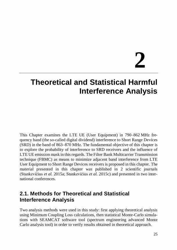
The idea of Monte-Carlo simulation can be seen in the Fig. 2.1.
Fig. 2.1. Basis of Monte-Carlo method (Gao et al. n.d.)
Fig. 2.1 identifies the general idea of SEAMCAT (ECO 2010) software tool
that was used in this study: SEAMCAT can use different input parameters in order to get the required distribution of out parameter. The workspaces of SEAMCAT
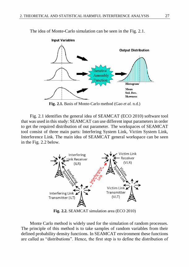
tool consist of three main parts: Interfering System Link, Victim System Link,
Interference Link. The main idea of SEAMCAT general workspace can be seen
in the Fig. 2.2 below.
Fig. 2.2. SEAMCAT simulation area (ECO 2010)
Monte Carlo method is widely used for the simulation of random processes. The principle of this method is to take samples of random variables from their
defined probability density functions. In SEAMCAT environment these functions
are called as “distributions”. Hence, the first step is to define the distribution of
28 2. THEORETICAL AND STATISTICAL HARMFUL INTERFERENCE ANALYSIS
possible values of the parameters of radiocommunications system under study
(e.g. operating frequencies, powers, antenna heights, positions of transmitter and
receiver, etc.). Then the analysis toll uses these distributions to generate random
samples (they are called snapshots or trials in the program). In the next step SEAMCAT calculates the strength of desired signal and for interfering signal for
each trial. The results are stored in data arrays. Then SEAMCAT in each snapshot
compares interference criterion of the wanted and unwanted signals at victim re-ceiver. In the last step the tool gives the probability of interference.
In SEAMCAT software tool we always have to describe (ECO 2010):
Interfering System Link with Interfering Link Transmitter and Inter-fering Link Receiver.
Victim System Link with Victim Link Transmitter and Victim Link Receiver.
The results of the Interference Link are calculated at each snapshot with the
possible interference criterion – carrier to interference ratio C/I, carrier to inter-
ference and noise ratio C/(I+N), interference to noise ratio I/N, noise and interfer-ence to noise ratio (N+I)/N and possible propagation models – Free Space model
(Molisch 2011), Extended Hata (Medeisis & Kajackas 2000), Extended Hata-
SRD (Chee & Kürner 2010), ITU-R P.1546 (Ostlin et al. 2003), Spherical diffrac-tion (Shen 1996), Longley Rice propagation (Visotsky et al. n.d.), IEEE 802.11
Model C (Sommer et al. 2011), Winner propagation (Begovic et al. n.d.). The list
of propagation models is continually extended according to the requirements. The main spectrum engineering cases can be addressed using SEAMCAT
software tool (ECO 2010):
Generic co-existence (sharing and compatibility) studies between different radiocommunications systems (mobile, broadcasting,
fixed) operating in the co-channel or adjacent channel case;
Evaluation of masks for transmitter or receiver;
Evaluation of various limits for given system parameters, such as
unwanted emissions in a spurious domain as well as out-of-band emissions, blocking and intermodulation levels.
With SEAMCAT various radiocommunications services could be modelled,
such as (ECO 2010; Zhang Meng et al. 2013; Li et al. 2012; Maqbool et al. 2008):
Broadcasting Services – terrestrial systems and Earth stations;
Mobile Services – Land Mobile Systems (LMS), Short Range De-
vices (SRD) and components of satellite systems based on Earth sur-face;
Fixed Services – Point-to-Point (P-P) and Point-to-Multipoint (PMP) fixed systems.
2. THEORETICAL AND STATISTICAL HARMFUL INTERFERENCE ANALYSIS 29
SEAMCAT tool is very popular in European Union Spectrum Engineering
working groups.
2.2. Electromagnetic Compatibility Problems in 800 MHz Frequency Band
World radiocommunication conference 2007 (WRC-07) allocated on a primary
basis the 790–862 MHz band to mobile services in Region 1 as from 17 June 2015, and in some CEPT countries it is possible to utilise this band for mobile services
before 2015, in accordance with the provisions of the Radio Regulations (ITU
2012). The 22nd meeting of ECC (Vienna, March 2009) agreed to develop a Deci-
sion on harmonised technical and regulatory conditions in the band 790–862 MHz
in order to meet the needs of industry and administrations. ECC/DEC/(09)03 describes common and minimal (least restrictive) technical
conditions for the band 790–862 MHz. These technical conditions will provide
significant economies of scale and facilitate the introduction of new applications
depending on national decisions. The ECC recognises that implementation of mobile/fixed communications networks in the band 790–862 MHz based on
common and minimal (least restrictive) technical conditions and on harmo-
nised frequency arrangements will maximise the opportunities and benefits for
end users and will secure future investments by providing economy of scale. Ta-
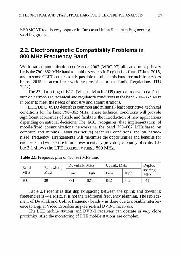
ble 2.1 shows the LTE frequency range 800 MHz.
Table 2.1. Frequency plan of 790–862 MHz band
Band,
MHz
Bandwidth,
MHz
Downlink, MHz Uplink, MHz Duplex
spacing,
MHz Low High Low High
800 30 791 821 832 862 –41
Table 2.1 identifies that duplex spacing between the uplink and downlink
frequencies is –41 MHz. It is not the traditional frequency planning. The replace-
ment of Dowlink and Uplink frequency bands was done due to possible interfer-
ence to Digital Video Broadcasting-Terrestrial DVB-T receivers. The LTE mobile stations and DVB-T receivers can operate in very close
proximity. Also the monitoring of LTE mobile stations are complex.

30 2. THEORETICAL AND STATISTICAL HARMFUL INTERFERENCE ANALYSIS
Fig. 2.3 shows the LTE 800 downlink / uplink channel plan. Each part is
30 MHz (6 blocks of 5 MHz), 11 MHz duplex gap.
Fig. 2.3. 800 MHz band plan
800 MHz LTE frequency band can interfere with DVB-T and SRD (Short Range Devices). Those frequencies are quite close, so there could be an interfer-
ence problem.
Table 2.2 shows the actual LTE channel widths and the maximum number of
resource block. LTE resource blocks as well as bit rate dependence on the channel width.
Table 2.2. LTE resource blocks
Channel bandwidth, MHz
Maximum number of resource blocks
(transmission bandwidth
configuration)
Maximum occupied
bandwidth, MHz
3 15 2.7
5 25 4.5
10 50 9
15 75 13.5
20 100 18.0
In this study we assumed that LTE used 10 MHz channel (852–862 MHz),
the maximum available resource blocks – 50, bitrate – 20 Mbit/s. LTE Base sta-
tion and User Equipment in 800 MHz frequency band are able to use only 10
channel and narrower.

2. THEORETICAL AND STATISTICAL HARMFUL INTERFERENCE ANALYSIS 31
Table 2.3 shows the source specification 3GPP TS 36.101 (corresponding
ETSI reference number TS 136 101) which provides the requirements for LTE
UE unwanted emissions (ETSI 2011a).
Table 2.3. 3GPP TS 36.101 LTE UE spectrum emission mask
ΔfOOB,
MHz
Spectrum emission limit (dBm)/ Channel bandwidth Measurement
bandwidth 1.4
MHz
3.0
MHz
5
MHz
10
MHz
15
MHz
20
MHz
± 0–1 –10 –13 –15 –18 –20 –21 30 kHz
± 1–2.5 –10 –10 –10 –10 –10 –10 1 MHz
± 2.5–
2.8 –25 –10 –10 –10 –10 –10 1 MHz
± 2.8–5 –10 –10 –10 –10 –10 1 MHz
± 5–6 –25 –13 –13 –13 –13 1 MHz
± 6–10 –25 –13 –13 –13 1 MHz
± 10–15 –25 –13 –13 1 MHz
± 15–20 –25 –13 1 MHz
± 20–25 –25 1 MHz
NOTE: As a general rule, the resolution bandwidth of the measuring equipment should be equal to the measurement bandwidth. However, to improve measurement accuracy, sensitivity and effi-ciency, the resolution bandwidth may be smaller than the measurement bandwidth. When the reso-lution bandwidth is smaller than the measurement bandwidth, the result should be integrated over the measurement bandwidth in order to obtain the equivalent noise bandwidth of the measurement bandwidth.
The spectrum emission mask identified in Table 2.3 is recommended by ECC
Project Team 1 (ECC PT1).
2.3. Main Information of Short Range Devices
The SRD developments within the band 863–870 MHz should adhere to the fol-
lowing strategy:
The band 863–865 MHz should continue to be available for wireless
audio applications and wireless microphones as well as for narrow band analogue voice devices within the sub-band 864.8–865 MHz.
32 2. THEORETICAL AND STATISTICAL HARMFUL INTERFERENCE ANALYSIS
The band 868–870 MHz should continue to be available for SRD ap-plications within sub-bands as already introduced in ERC Recom-
mendation 70-03.
The frequency band 863–870 MHz should be considered for NON specific spread spectrum SRD applications by using Direct Sequence
Spread Spectrum (DSSS) and/or Frequency Hopping Spread Spec-
trum (FHSS) with a power level of 25 mW.
The frequency band 862–863 MHz is currently reserved for govern-
ment use in a number of countries and should not be designated for
other radio services.
Any networking and use of repeaters within SRD bands 863–
870 MHz should be limited to single owned use within the premises
of the owner operator.
The technical parameters of the equipment used in these applications are de-
fined within the following annexes of CEPT/ERC/REC 70-03 (ERC 2015):
Annex 1 Non-specific Short Range Devices. This annex covers fre-quency bands and regulatory as well as informative parameters rec-
ommended primarily for Telemetry, Telecommand, Alarms and
Data in general and other similar applications.
Annex 7 Alarms. This annex covers frequency bands and regulatory
as well as informative parameters recommended exclusively for
alarm systems including social alarms and alarms for security and safety.
Annex 10 Radio microphones. This annex covers frequency bands
and regulatory as well as informative parameters recommended ex-clusively for radio microphone applications including assistive lis-
tening devices, wireless audio and multimedia streaming systems
Annex 13 Wireless Audio Applications. This annex covers fre-quency bands and regulatory as well as informative parameters rec-
ommended exclusively for wireless audio applications.
The Short Range devices defined in Annex 1, Annex 7, Annex 10 and Annex
13 of CEPT/ERC/REC 70-03 (ERC 2015) were used in the analysis of interfer-ence occurrence in the frequency band of 790–862 MHz.

2. THEORETICAL AND STATISTICAL HARMFUL INTERFERENCE ANALYSIS 33
More detailed information regarding Annex 1, 7, 10, 13 of CEPT/ERC/REC
70-03 is described in Table 2.4.
Table 2.4. Technical parameters and values of existing short range devices (ETSI 2008;
ETSI 2012)
Application
Category
Sub-
band
Freq low,
MHz
Freq high,
MHz
Power,
mW BW, kHz
Duty
cycle, %
Non-specific Short Range Devices
Annex 1
f 868 868.6 25 na 1
g 868.7 869.2 25 na 0.1
h 869.3 869.4 10 25 100
i 869.4 869.65 500 25 10
k 869.7 870 5 na 100
Alarms
Annex 7
a 868.6 868.7 10 100 0.1
b 869.25 869.3 10 25 0.1
c 869.65 869.7 25 25 10
d 869.2 869.25 10 25 0.1
Radio microphones
Annex 10 c 863 865 10 200 100
Wireless Audio Applications
Annex 13 a 863 865 10
300 or
600 100
b 864.8 865 10 50 100
Table 2.4 identifies the main frequency bands, maximum allowed transmis-
sion power, channel bandwidth BW, duty cycle for Short Range devices. The
maximum transmission power is allowed to Non-specific Short Range Devices –
500 mW. The widest allowable channel bandwidth BW is 600 kHz. The Non-specific Short Range Devices, Radio microphones and Wireless Audio Applica-
tions can have the duty cycle up to 100 %.

34 2. THEORETICAL AND STATISTICAL HARMFUL INTERFERENCE ANALYSIS
Parameters of victims (LTE UE interferer, SRD victim). Table 2.5 lists the
values used in the simulations of existing SRDs as victims.
Table 2.5. Parameters of short range devices
Rec. 70-03 Annex 1 Annex 7 Annex 10 Annex 13
Bandwidth,
kHz 100 25 200 50
Sensitivity,
dBm –101 –107 –90 –104
C/(I+N), dB 8 8 17 8
Selectivity EN 300 220
(ETSI 2012) EN 300 220
EN 301 357
(ETSI 2008) EN 300 220
Power EIRP,
dBm 14 14 14 10
Operation
range, m 30 30 30 30
Antenna Omni directional 0 dBi gain
Frequency,
MHz 868.1 869.65 864.25 864.975
These SRDs were used in SEAMCAT simulations. In practical measure-ments only Non-specific SRD were used to verify results obtained in SEAMCAT
simulations.
2.4. Interference Situation for Theoretical and Monte-Carlo Simulations
Fig. 2.4 shows the test plan used for simulations with SEAMCAT (Monte-Carlo
simulation software):
Fig. 2.4. Simulation plan

2. THEORETICAL AND STATISTICAL HARMFUL INTERFERENCE ANALYSIS 35
Fig. 2.5 shows the methodology of simulations with SEAMCAT.
Cell radius
SRD Tx SRD Rx
LTE BS
LTE UE
dmax
Fig. 2.5. SEAMCAT simulation
LTE UE and SRD is in an open area up to 10 m. The simulation radius was limited to 10 m, in order to model the anticipated typical situation of both LTE
UE and SRD devices were placed in the same room.
The simulations distance between them varies stochastically up to 10 m ra-
dius. SRD Rx/Tx simulation environment: propagation model – Extended Hata SRD, local environment – indoor. LTE UE Rx/Tx simulation environment: prop-
agation model – Extended Hata, local environment – indoor. In each case the
500000 calculations were performed. The main reason of this decision is seen in the Fig. 2.6.
Fig. 2.6 shows the Iteration number dependence on probability of interfer-
ence. It is seen that probability of interference becomes steady after the iteration
number is higher than 50 000. In this study ten times higher number of iterations that were used in each simulation in order to warrant the reliability of simulated
results.

36 2. THEORETICAL AND STATISTICAL HARMFUL INTERFERENCE ANALYSIS
Fig. 2.6. Iteration number dependence on probability of interference
Distance between Interfering Link Transmitter (ILT) and Interfering Link
Receiver (ILR) was calculated using real GSM network in Vilnius city. Average
calculated coverage radius was 350 m. SRDs operation radius was set to 30 m. We focused on most critical situation of LTE vs. SRD co-existence, in which
a LTE User Equipment (UE) device is in the same room with an SRD unit. In
2009 was decided (CEPT Report 31 (CEPT 2009b)) that the chosen frequency
plan in 790-862 MHz band should be based on the FDD mode. LTE mobile networks in 800 MHz band may influence to DVB-T networks
in the lower adjacent band and to SRD in 863–870 MHz and in the upper adjacent
band. Since LTE bandwidths can vary up to 20 MHz, the usage of such channels can produce high levels of OOB emissions. According to Fig. 2.3 – SRD devices
can be interfered by uplink of LTE networks, i.e. LTE User Equipment emissions.
It was estimated that LTE UE use the closest 10 MHz channel (852–862 MHz) according to SRD band, maximum emitted power – 23 dBm (all possible resource
blocks allocated). In the Table 2.3 it is seen the LTE UE spectrum emission mask
used in simulations according to 3GPP TS 36.101 (corresponding ETSI reference
number TS 136 101) (ETSI 2011a).
0
1
2
3
4
5
6
7
8
9
10P
rob
abili
ty o
f in
terf
ere
nce
, %
Iteration number
2. THEORETICAL AND STATISTICAL HARMFUL INTERFERENCE ANALYSIS 37
2.5. Filter Bank Multicarrier Transmission Technique as a Possible Orthogonal Frequency-Division
Multiplexing Improvement
FBMC method has its roots in the pioneering works of Chang (R. Chang 1966) and Saltzberg (Saltzberg 1967) who introduced multicarrier techniques over two
decades before the introduction and application of OFDM to wireless communi-
cation systems. The filter banks address the main disadvantages of OFDM men-tioned above. First, their subchannels can be optimally designed in the frequency
domain to have desired spectral containment. Second, FBMC systems do not re-
quire redundant CP and thus are more spectral efficient.
Contrary to OFDM where orthogonality must be ensured for all the carriers, FBMC requires orthogonality for the neighbouring sub-channels only. In fact,
OFDM exploits a given frequency bandwidth with a number of carriers, while
FBMC divides the transmission channel associated with this given bandwidth into a number of sub-channels. In order to fully exploit the channel bandwidth, the
modulation in the sub-channels must adapt to the neighbour orthogonality con-
straint and offset quadrature amplitude modulation (OQAM) is used to that pur-
pose (Lélé et al. 2008; Vangelista & Laurenti 2001; Siohan et al. 2002). The com-bination of filter banks with OQAM modulation leads to the maximum bit rate,
without the need for a guard time or cyclic prefix as in OFDM (Bellanger 2010).
FBMC system description (Bellanger 2010; Farhang-Boroujeny 2011b; Zakaria 2012; Farhang-Boroujeny 2009; H. Zhang et al. 2010; Kollár & Horváth
2012; Kollár et al. 2011; H. Z. H. Zhang et al. 2010):
Orthogonal filter bank structure. Filters fulfilling the Nyquist crite-rion
In FBMC, the overlap between subcarrier channels is mostly limited to the adjacent channels. In OFDM, on the other hand, there is sig-
nificant overlap among many subcarriers (if not among all the sub-
carriers) in the system. As a result, OFDM is likely to be more sen-
sitive to a carrier offset and doppler effects/mobility (Zhao & Haggman n.d.). More importantly, in an OFDM based multiple ac-
cess (called, OFDMA) network where each set of subcarriers may be
allocated to a different transmitting node, any loss of synchronization of carriers at different nodes can result in a significant loss of perfor-
mance.
Unlike OFDM that uses a guard interval (the cyclic prefix – CP) to manage channel distortion, FBMC resolves the problem of channel

38 2. THEORETICAL AND STATISTICAL HARMFUL INTERFERENCE ANALYSIS
distortion through some clever signal processing. The absence of
guard interval in FBMC results in an improved bandwidth efficiency.
Out-of-band radiation is much lower compared to OFDM.
Channel equalization is more complex due to inter-symbol-interfer-
ence. But the fractionally spaced equalizer is recognized as providing
the best performance and the highest efficiency (Ihalainen et al. 2007).
In cognitive radios, a network of cognitive nodes collaboratively sense the spectrum of a wide frequency band, find the spectrum holes
(the unused parts of the band) and establish transmission through
these spectrum holes. In such situations, FBMC may be a preferred
choice over OFDM (X. Zhu et al. 2007; Rhee & Cioffi 2000). The above advantages of FBMC do not come for free. An FBMC is often
more complex to implement than its OFDM counterpart (Renfors et al. 2013;
Premnath et al. 2013). Therefore, in applications where OFDM performs well, e.g., point-to-point transmission is an environment with low to medium mobility,
OFDM may be preferred. FBMC, on the other hand, is expected to find applica-
tions in multiple access and cognitive radio networks (Datta et al. 2011; Medjahdi, Terre, et al. 2011; Schellmann et al. 2014).
2.5.1. Main Principles of Filter Bank Multicarrier Transmission Technique
The Filter Bank Multicarrier (FBMC) transmission technique leads to an en-
hanced physical layer for conventional communication networks and it is an ena-
bling technology for the new concept of cognitive radio. Cognitive radio is a dif-ferent context for communication systems.
At the physical layer, it implies that two functions have to be performed by
the terminals, namely the assessment of the spectral environment and opportunis-tic transmission. The physical layer reports to the upper level decision layers and
it receives the instructions for optimal transmission. FBMC techniques have the
potential to enhance the performance of synchronized conventional networks and add new functionalities.
The Filter Bank Multicarrier (FBMC) are an enabling technology for the ef-
ficient deployment and the acceptance of opportunistic networks. Finally, FBMC
techniques lead to a new physical layer which offers performance gains and addi-tional functionalities in conventional networks.
2. THEORETICAL AND STATISTICAL HARMFUL INTERFERENCE ANALYSIS 39
Fig. 2.7 shows the main principles of FBMC operation (Bellanger 2010; Far-
hang-Boroujeny 2011b).
h(t)
)2
(T
th
)2
(T
th
)2
(T
th
)(0 tS I
)(1 tS I
)(1 tS I
N
)(1 tjS Q
N
)(1 tjS Q
)(0
tjSQ
)2
2(
t
Tj
e
)2
2)(1(
t
TNj
e
tfj ce
2
}{)(tx
h(t)
h(t)
Fig. 2.7. Structure of Filter Bank Multicarrier Transmission technique (Farhang-Boroujeny 2011b)
Fig. 2.7 presents the block diagram of an FBMC transmitter. The data signals
S0(t) through SN-1(t) are continuous-time signals associated with transmit symbol
sequences that are defined, using the notations (Farhang-Boroujeny 2011b):
n
kk nTtnStS ),(][)( for 1N , ... 1, 0,k (2.1)
where Sk[n] are complex-valued (e.g., QAM or PSK) data symbols that may be written as (Farhang-Boroujeny 2011b):
],[][][ njSnSnSQk
Ikk (2.2)
where the superscripts I and Q refer to the in-phase and quadrature parts, respec-
tively. T denotes the symbol spacing at each subcarrier channel. Also, note that at
each subcarrier channel, the real and imaginary parts of Sk[n] are separated and time staggered by T/2. This is done through the pulse shaping filter h(t) which is
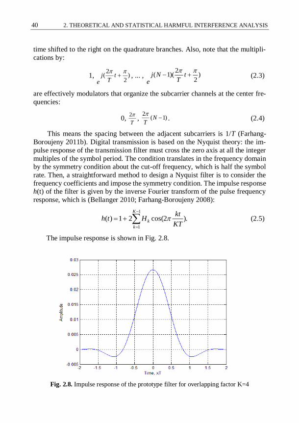
40 2. THEORETICAL AND STATISTICAL HARMFUL INTERFERENCE ANALYSIS
time shifted to the right on the quadrature branches. Also, note that the multipli-
cations by:
1, )2
2(
t
Tj
e, ... , )
2
2)(1(
t
TNj
e (2.3)
are effectively modulators that organize the subcarrier channels at the center fre-
quencies:
0, T
2, )1(
2N
T
. (2.4)
This means the spacing between the adjacent subcarriers is 1/T (Farhang-
Boroujeny 2011b). Digital transmission is based on the Nyquist theory: the im-
pulse response of the transmission filter must cross the zero axis at all the integer
multiples of the symbol period. The condition translates in the frequency domain by the symmetry condition about the cut-off frequency, which is half the symbol
rate. Then, a straightforward method to design a Nyquist filter is to consider the
frequency coefficients and impose the symmetry condition. The impulse response h(t) of the filter is given by the inverse Fourier transform of the pulse frequency
response, which is (Bellanger 2010; Farhang-Boroujeny 2008):
.)2cos(21)(1
1
K
k
kKT
ktHth (2.5)
The impulse response is shown in Fig. 2.8.
Fig. 2.8. Impulse response of the prototype filter for overlapping factor K=4

2. THEORETICAL AND STATISTICAL HARMFUL INTERFERENCE ANALYSIS 41
A section of the filter bank derived in a manner that the sub-channels with
even index (odd index) do not overlap. The main idea is shown in the Fig. 2.9
below (Bellanger 2010; Ringset et al. 2011).
)(mMdi
)(2
mMdi
iK Ki )1( Ki )2(
KMiFFT
sumoverlapSP //
)(nx
Fig. 2.9. General block diagram of the transmitter of Filter Bank Multicarrier
Transmission technique (Bellanger 2010)
Details of the implementation are given for the overlapping factor K = 4. The
Fig. 2.9 shows that the sub-channels with indices i and i+2 are separated and do
not overlap. On the contrary, sub-channel i+1 overlaps with both and orthogonal-ity is necessary. It is provided by using real inputs of the iFFT for i and i+2, and
imaginary inputs for i+1, or the inverse (Ihalainen et al. 2007; Waldhauser 2009).
Due to the overlapping in the time domain of the iFFT outputs and FFT in-puts, a significant amount of redundancy is present in the computations. An effi-
cient approach to reduce this redundancy is the so-called polyphase network with
fast Fourier transform (PPN-FFT) scheme (Bellanger 2012). The PPN-FFT scheme will be presented in the next section.
The next important parameter: intersub-channel interference frequency re-
sponse is required because it determines the modulation scheme. In the time do-
main, the interference filter impulse response g(t) is given by the inverse Fourier transform (Bellanger 2010):
,)2cos(2)( 22
12T
tj
eKT
tGGtg
(2.6)
where G2, G2 – filter coefficients, K – overlapping factor.

42 2. THEORETICAL AND STATISTICAL HARMFUL INTERFERENCE ANALYSIS
This is a crucial result, which determines the type of modulation which must
be used to dodge interference.
Fig. 2.10. Frequency responses of the sub-channel filter and
interference filter (Bellanger 2010)
Fig. 2.10 shows the relationship between send-receive filter and interference
filter characteristic. The zero crossings are interleaved and it is the basis for the
OQAM modulation.
),/sin()/cos(22
TtjTte T
tj
(2.7)
equation 2.7 reflects the symmetry of the frequency coefficients and, due to this factor, the imaginary part of g(t) crosses the zero axis at the integer multiples of
the symbol period T while the real part crosses the zero axis at the odd multiples
of T/2 (Bellanger 2010).
2.5.2. Polyphase Fast Fourier Transform Networks in the Filter Bank Multicarrier Transmission
The polyphase FFT networks in the FBMC were used to reduce the computational
complexity. The structure for the implementation of the filter bank in the trans-
mitter is shown in the Fig. 2.11 (Farhang-Boroujeny 2011b; Bellanger 2010).

2. THEORETICAL AND STATISTICAL HARMFUL INTERFERENCE ANALYSIS 43
)(0
mMd
)(1
mMd
)(1
mMdM
0H
1H
1MH
1Z
)1( MZ
)( nxiDFT
Fig. 2.11. Polyphase FFT implementation of the transmitter filter bank (Bellanger 2010)
In the implementation, the transmitter output is the sum of the outputs of the
filters of the bank. Thus, the processing associated with the filter elements )( M
pZH
can be carried out after the summation which is performed by the iDFT (Shaat & Bader 2010; Simon Plass, Armin Dammann, Stefan Kaiser 2007).
FBMC systems are likely to coexist with OFDM systems. Since FBMC is, in
fact, an evolution of OFDM, some compatibility can be expected. Compatibility begins at the specification and system parameter level. The sampling frequency is
the same and the sub-channel spacing of FBMC is equal to the sub-carrier spacing
of OFDM or it is a sub-multiple, so that the FFT is the same, or a subset of the FFT is the same. In OFDM systems, the sub-carriers are integer multiples of the
spacing. Similarly, the sub-channels in FBMC systems are centered on the integer
multiples of the spacing (Farhang-Boroujeny 2009; Farhang-Boroujeny 2011b;
Bellanger 2010).
2.6. Evaluation of Possible Interference Using Long-Term Evolution with Orthogonal Frequency-Division Multiplexing and Filter Bank Multicarrier
Transmission
The main problem of this work is OFDM sub-carriers out-of-band emission. If we could reduce this level we could avoid electromagnetic compatibility problems or
decrease them. FBMC transmission technique seems like a possible solution to

44 2. THEORETICAL AND STATISTICAL HARMFUL INTERFERENCE ANALYSIS
facilitate this problem. The main differences between OFDM and FBMC are seen
by comparing the time and frequency domains of the filters (see Fig. 2.12).
Fig. 2.12. Time representation of Orthogonal frequency-division multiplexing rectangular window and Filter Bank Multicarrier Transmission filter response
FBMC uses a filter, which is a longer period of time, and continues through
a number of symbols (typical number is 4 symbols, and this parameter is called the overlapping factor K) (Mitra 1996). Generally, overlapping factor K is an in-
teger number and, in the frequency domain, it is the number of frequency coeffi-
cients which are introduced between the FFT filter coefficients. Using a longer filter, we can make the frequency response narrower. Longer filter FBMC has
advantages and disadvantages:
The advantage is that the spectrum of each sub-carrier basically co-
vers just particular block of the adjacent sub-carriers, so much spec-
trum is used sparingly and in the particular traffic management sys-tems, many users systems can be considerably more flexible.
The disadvantages are that it is necessary to send data over longer
blocks, need some start up interval to the FBMC filters start working
completely. It is also becoming more complex issues such as channel estimation and equalization.
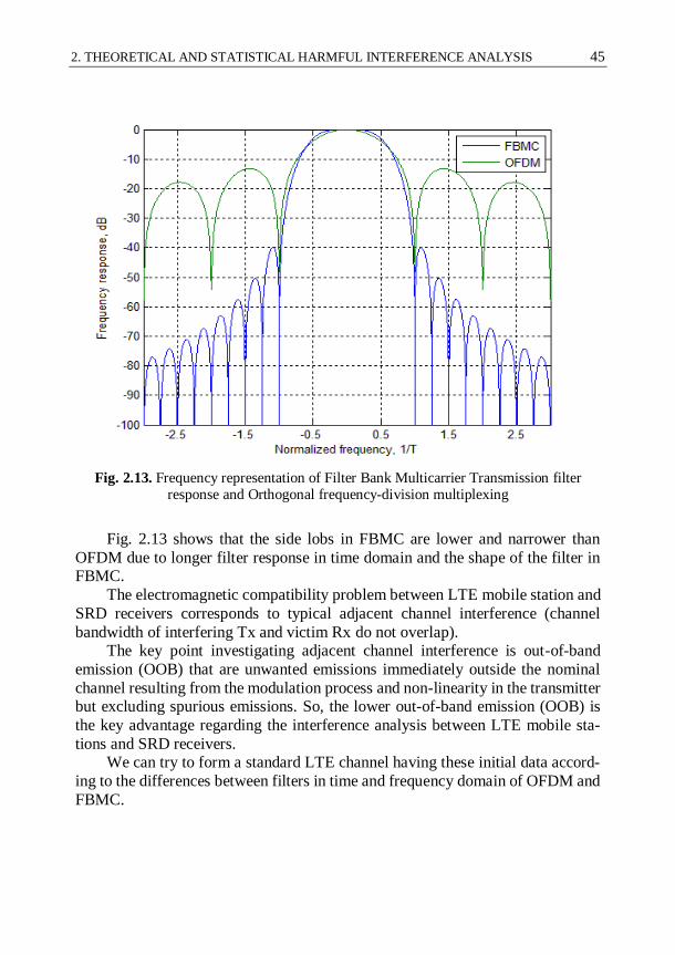
2. THEORETICAL AND STATISTICAL HARMFUL INTERFERENCE ANALYSIS 45
Fig. 2.13. Frequency representation of Filter Bank Multicarrier Transmission filter
response and Orthogonal frequency-division multiplexing
Fig. 2.13 shows that the side lobs in FBMC are lower and narrower than
OFDM due to longer filter response in time domain and the shape of the filter in FBMC.
The electromagnetic compatibility problem between LTE mobile station and
SRD receivers corresponds to typical adjacent channel interference (channel
bandwidth of interfering Tx and victim Rx do not overlap). The key point investigating adjacent channel interference is out-of-band
emission (OOB) that are unwanted emissions immediately outside the nominal
channel resulting from the modulation process and non-linearity in the transmitter but excluding spurious emissions. So, the lower out-of-band emission (OOB) is
the key advantage regarding the interference analysis between LTE mobile sta-
tions and SRD receivers. We can try to form a standard LTE channel having these initial data accord-
ing to the differences between filters in time and frequency domain of OFDM and
FBMC.

46 2. THEORETICAL AND STATISTICAL HARMFUL INTERFERENCE ANALYSIS
The main LTE channel parameters according to 3GPP standard (ETSI 2011a)
are presented in Table 2.6.
Table 2.6. LTE channel parameters (ETSI 2011b)
Channel Bandwidth, MHz 5 10 15 20
Frame Duration, ms 10
Sub-frame Duration, ms 1
Sub-carrier Spacing, kHz 15
Sampling Frequency, MHz 7.68 15.36 23.04 30.72
FFT Size 512 1024 1536 2048
Occupied Sub-carriers (inc. DC sub-carrier) 301 601 901 1201
Occupied Channel Bandwidth, MHz 4.515 9.015 13.515 18.015
10 MHz channel to simulate the worst case situation that one user occupies the whole channel and emits maximum allowed power was used in this analysis.
The difference between 10 MHz channel in OFDM and FBMC is seen in Fig. 2.14
below.
Fig. 2.14. Orthogonal frequency-division multiplexing and Filter Bank Multicarrier
Transmission spectrum comparison than 10 MHz channel is used

2. THEORETICAL AND STATISTICAL HARMFUL INTERFERENCE ANALYSIS 47
Fig. 2.14 shows the difference between OFDM and FBMC in the out-of-band
area due to the different physical layer mechanisms which were presented in this
sector. FBMC has approximately 20 dB less in the out-of-band emission. This
feature will be used in further studies of electromagnetic compatibility.
Fig. 2.15. Long-Term Evolution emission mask based on TS 136 101 and
possible Filter Bank Multicarrier Transmission emission mask (RBW 100 kHz)
Fig. 2.15 shows two proposed spectrum emission masks were used in Monte-
Carlo analysis section subsequently. The emission mask of LTE systems using OFDM will be based on TS 136 101 recommendation. The emission mask of LTE
systems using FBMC will be based on TS 136 101 recommendation with 20 dB
reduction of emission levels according to simulation results presented in Fig. 2.14.
2.7. Results of Theoretical Evaluation of Interference Potential Applying Minimum Coupling Loss Method
First of all the Minimum Coupling Loss (MCL) method was examined, which evaluates what spatial separation distance is needed between the interferer and
victim in order to avoid interference:
,rxrxtx UEBCGSPRPC (2.2)

48 2. THEORETICAL AND STATISTICAL HARMFUL INTERFERENCE ANALYSIS
where RPC – Required Path Loss, Ptx – EIRP of interferer, Srx – victim sensitivity
level, Grx – victim antenna gain, UEBC – Unwanted Emissions Bandwidth Con-
version or C/I value.
This method was applied in this situation for e.g. non-specific SRD devices. Considering two cases of adjacent channel interference: a) OFDM emission mask,
b) FBMC emission mask.
RPCOFDM = –23 dBm/100 kHz –(–101 dBm) + 0 dB + dB = 86 dB, (2.3)
RPCOFDM = –46 dBm/100 kHz –(–101 dBm) + 0 dB + dB = 86 dB. (2.4)
We can translate the calculated RPC values (see formulas 2.3 and 2.4) to
spatial required distance using Free Space Loss propagation model. This model is suitable in this case, because the LTE UE and SRD devices are always in line of
sight. So the required separation distances are 389 and 39 m for OFDM and
FBMC cases, respectively.
According to 3 dB optional margin and C/(I+N) = 8 dB interference criterion are used regarding to EN300220 standard (ETSI 2012). So the MCL method
shows that the LTE UE could have interference influence to SRD devices in ad-
jacent band at distances of up to 389 m if OFDM mask is used and at distances of up to 39 m. The following calculations show the great potential influence of pos-
sible FBMC emission mask utilization – spatial distance could be reduced from
389 to 39 m.
2.8. Results of Theoretical Evaluation of Interference Potential Applying Monte-Carlo Method
The results of theoretical evaluation of interference potential applying Monte-Carlo Method are presented in this chapter. Three different separation distances
were analysed in order to identify the minimum separation distance between LTE
User Equipment and Short Range devices. The simulation radius was limited to 10 m, in order to model the anticipated typical situation of both LTE User Equip-
ment and Short Range devices were placed in the same room. The simulations
distance between them varies stochastically up to 10 m radius. In each case the
500000 calculations were performed. Table 2.7 shows the simulation results using Monte-Carlo method in terms
of probability of interference (PoI) from LTE UE to different victim SRD devices.
The probability of interference (PoI) less than 5% is considered to be a sufficient level.

2. THEORETICAL AND STATISTICAL HARMFUL INTERFERENCE ANALYSIS 49
Table 2.7. Simulated LTE UE to SRD adjacent band interference probability
Parameter SRD types according annexes of ERC/Rec 70-03:
Annex 1 Annex 7 Annex 10 Annex 13
dmax = 10 m
PoI with OFDM, % 21.11 17.76 50.52 32.27
PoI1 with FBMC, % 4.02 2.85 20.22 9.68
dmax = 20 m
PoI with OFDM, % 13.85 10.62 34.30 19.92
PoI with FBMC, % 2.20 1.76 11.27 4.85
dmax = 50 m
PoI with OFDM, % 7.66 4.41 15.07 8.52
PoI with FBMC, % 1.04 0.81 4.72 2.22
Note1: dmax – separation distance between LTE UE and SRD Rx.
LTE UE using OFDM does not produce interference to SRD receivers sepa-
ration distance higher than 50 m ± 5 % (see Table 2.7). The obtained results show a significant change in the level of probability of interference using FBMC. The
obtained results of simulations show the significant level of probability of inter-
ference using OFDM. Considerring three described interference situations system with OFDM creates up 50.52 % interference probability (dmax = 10 m case), up
34.30% interference probability (dmax = 20 m case) and up 15.07 % interference
probability (dmax = 50 m case). Results with FBMC can reduce the interference level accordingly from 50.52 % to 20.22% (dmax = 10 m case), from 34.30% to
11.27% (dmax = 20 m case) and from 15.07 % to 4.72 % (dmax = 50 m case). In
most crucial situation (dmax = 10 m case) the Short Range Devices which corre-
spond to Annex 1 and Annex 7 could co-exist in the same room assumption (sim-ulation radius dmax up to 10 m) if FBMC emission mask would use in LTE mobile
networks (with assumption that probability of interference (PoI) less than 5 % is
considered like a sufficient level). With higher separation distance even more types of SRD can co-exist with LTE user equipment. When the separation distance
is longer than 50 m, the interference effect is validated as disappeared regarding
all investigated SRD types using FBMC. Confidence interval of all simulations is
95%. In all simulations the interference criterion was used C/(I+N) = 8 dB or 17 dB for Annex 10 (as described in: EN 300 220 (ETSI 2012), EN 301 357 (ETSI
2008)).

50 2. THEORETICAL AND STATISTICAL HARMFUL INTERFERENCE ANALYSIS
2.9. Conclusions of Chapter 2
1. FBMC technique proposed as a possible facilitator in order to avoid LTE
UE 800 MHz interference to SRD operating in the band of 863–870 MHz.
FBMC technique is more spectrum efficient – Out-of-Band emissions lev-els are approximately 20 dB less comparing to OFDM.
2. Performed simulations with hypothetical LTE networks using OFDM and
FBMC identified the significantly higher level of probability of interfer-
ence using OFDM than FBMC technique. LTE UE using OFDM does not produce interference to SRD receivers separation distance higher than 50
m ± 5%. Considering three described interference situations (three differ-
ent separations distances dmax), it is concluded that LTE systems with FBMC technique can reduce the probability of interference more than 2.5
times (dmax = 10 m case), more than 3 times (dmax = 20 m case) and more
than 3.2 times (dmax = 50 m case). Confidence interval of all simulations is 95 %. In most crucial situation (dmax = 10 m case) the Short Range De-
vices which correspond to Annex 1 and Annex 7 could co-exist in the
same room assumption (simulation radius dmax up to 10 m) if FBMC emis-
sion mask would use in LTE mobile networks (with assumption that prob-ability of interference (PoI) less than 5% is considered like a sufficient
level). When the separation distance is longer than 50 m, the interference
effect is validated as disappeared regarding all investigated SRD types using FBMC.
3. As an overall conclusion, it may be recommended that the limits of LTE
UE OOB emissions may need to be revised in order to ensure the reason-able degree of adjacent band co-existence with SRDs.

51
3 Experimental Investigation of
Harmful Interference Occurrence
This Chapter examines the measurements of Minimum Coupling Loss (MCL), real SRD device sensitivity, as well as potential of LTE UE 800 MHz interference
to SRD devices in the band of 863–870 MHz. Measurements reported in this chap-
ter aimed to examine the possibility of interference in practical use situation. Prac-
tical measurements were conducted so as to reproduce the situation that was ana-lysed in theoretical analysis chapter. Two different SRD devices were considered
as representative victims: Semtech SX1231 and Analog Devices ADF7023. All
measurements were performed in the laboratory of Electronics Faculty of Vilnius Gediminas Technical University in 2013. The material presented in this chapter
was published in one scientific journals (Stankevicius et al. 2015c) and presented
in one international conference. Also three presentations were made in Denmark
(Copenhagen) and Germany (Karlsruhe and Berlin) as a representative of Com-munication Regulatory Authority of the Republic of Lithuania at the SE24 work-
ing group of Electronic Communication Committee (ECC), which is official Eu-
ropean Union agency responsible for the development of common policies and regulations in electronic communications and related applications for Europe.
52 3. EXPERIMENTAL INVESTIGATION OF HARMFUL INTERFERENCE OCCURRENCE
3.1. Aim of Performed Experimental Investigation
This section aims to examine the possibility of interference in practical experi-
ment. Practical experiment was conducted to restore the situation that would be similar as well as theoretical simulations. This section consists of three parts:
Minimum Coupling Loss (MCL) measurements. The MCL method calculates the isolation required between interferer and victim to en-
sure that there is no interference. The aim is to assess the size of the
MCL in 863–870 MHz band. During the test were used real SRD devices.
Real SRD sensitivity level. The aim is to find out what is the real
SRD equipment sensitivity level.
LTE UE interference probability to SRD devices. The aim is to prac-
tically measure the extent to which SRD device can suffer interfer-ence effects from LTE UE.
Many countries in Europe are concerned of the interference potential be-
tween the LTE UE deployed in the band below 862 MHz to operation of ubiqui-
tous SRD devices in the band 863–870 MHz. The following study will contribute to the investigation of this issue.
3.2. Minimum Coupling Loss Measurements
This section provides the results of measurements of MCL observed for devices
operated in 863–870 MHz band in order to calculate the isolation required be-tween interferer and victim to ensure that there is no interference. The following
SRD prototypes were used during the measurements:
Semtech International AG SX1231 transceiver development kit.
Analog Devices ADF7023 transceiver development kit.
Both devices are classified as Non-specific Short Range Devices according
to Annex 1 of CEPT/ERC/REC 70-03 (ERC 2015) recommendation. The Annex 1 of CEPT/ERC/REC 70-03 covers frequency bands and regulatory as well as
informative parameters recommended primarily for Telemetry, Telecommand,
Alarms and Data in general and other similar applications. This annex also in-cludes references to the generic ultra wideband regulation which was primarily
developed to allow communication applications using ultra wideband technology
in bands below 10.6 GHz

3. EXPERIMENTAL INVESTIGATION OF HARMFUL INTERFERENCE OCCURRENCE 53
The main Semtech SX1231 and Analog Devices ADF7023 transceivers’ pa-
rameters used during the measurement are presented in Table 3.1.
Table 3.1. Main parameters of tested SRD transceivers
Main parameters Analog Devices ADF7023 Semtech SX1231
Frequency, MHz 868.1 868.1
Bandwidth, kHz 100 100
Throughput, kbits 57 57
Frequency deviation,
kHz
40 40
Modulation GFSK FSK
Modulation shaping Gaussian filter Gaussian filter
Packet length, bytes 16 16
CRC calculation,
on/off
on on
Automatic Frequency
Correction, on/off off off
Automatic Gain Con-
trol, on/off on on
Data coding Manchester Manchester
Transmitter Output
Power e.i.r.p1, dBm 0 0
Antenna type Omni Omni
Antenna gain, dBi 0 0
Note1: Transmitter Output Power = 0 dBm was used for the first measurement of MCL. For other measurements we used a different power as reported in relevant sections.
During the measurements two Semtech SX1231 (same configuration steps
for the Analog Devices ADF7023) devices were used, one configured as transmit-
ter and another one as receiver. Measuring set up: the transmitter emits a certain power, the receiver is used for signal level monitoring. Before doing the actual
measurements, the correspondence between SRD power management setting and
emitted power at the transmitter, as well as correspondence of measured receive power to real value were verified by using professional spectrum analyser Anritsu
Spectrum Master MS2721B. All following power references mean reference to
EIRP.
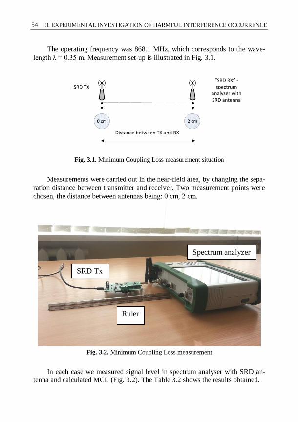
54 3. EXPERIMENTAL INVESTIGATION OF HARMFUL INTERFERENCE OCCURRENCE
The operating frequency was 868.1 MHz, which corresponds to the wave-
length λ = 0.35 m. Measurement set-up is illustrated in Fig. 3.1.
SRD TX“SRD RX” - spectrum
analyzer with SRD antenna
0 cm 2 cm
Distance between TX and RX
Fig. 3.1. Minimum Coupling Loss measurement situation
Measurements were carried out in the near-field area, by changing the sepa-
ration distance between transmitter and receiver. Two measurement points were
chosen, the distance between antennas being: 0 cm, 2 cm.
Fig. 3.2. Minimum Coupling Loss measurement
In each case we measured signal level in spectrum analyser with SRD an-
tenna and calculated MCL (Fig. 3.2). The Table 3.2 shows the results obtained.
Spectrum analyzer
SRD Tx
Ruler

3. EXPERIMENTAL INVESTIGATION OF HARMFUL INTERFERENCE OCCURRENCE 55
Table 3.2. Minimum Coupling Loss measurements results
Distance between Rx and Tx
Average MCL
Analog Devices
ADF7023, dB
Average MCL
Semtech SX1231, dB
0 cm 15 10
2 cm 26 24
Minimum Coupling Loss value was calculated by simple expression:
LMCL = TxEIRP – Rx, (3.1)
where LMCL – Minimum Coupling Loss, TxEIRP – transmitter output power EIRP,
Rx – received signal level.
The reported results indicate that the MCL can range from 10–15 dB at zero
distance to around 25 dB at a distance of few centimetres.
3.3. Real Short-Range Devices Device Sensitivity Level
This measurement was designed to establish the real sensitivity level of (repre-
sentative) SRD devices. All measurements were performed in a standard office
room. Room size is 9 on 8 m.
3.3.1. Semtech SX1231 Receiver’s Sensitivity Level
In Semtech datasheet the following information can be found about the used de-
vice's sensitivity level (Table 3.3).
Table 3.3. Short Range device sensitivity levels from datasheet
Bandwidth, kHz Bitrate, kbit/s Sensitivity, dBm
5 1.2 –118
5 4.8 –114
40 38.4 –105
During the control measurement the respective SRD Tx and Rx were gradu-
ally removed from each other, monitoring incoming packages. The duration of the
measurements was 5 minutes and average values were calculated. Test criterion
for the normal Rx operation – PER (packets error ratio) not less than 10%. During

56 3. EXPERIMENTAL INVESTIGATION OF HARMFUL INTERFERENCE OCCURRENCE
the experiment it was observed that the connection was lost when the receive sig-
nal level dropped to an average of –95 dBm (see Fig. 3.3).
P, dBm
Measured minimum sensitivity level = -95 dBm
Optional margin = 3 dB
Operating level = -92 dBm
Typical wanted level = -72 dBm
Fig. 3.3. Measured sensitivity level for the Semtech receiver
Based on the established value of SRD sensitivity for given bandwidth, for
the subsequent measurements of interference in the 3rd part of this study, the vic-
tim SRD receiver was set to operate at receive levels:
–92 dBm, i.e. minimum wanted signal level, 3 dB above the sensi-
tivity level, and
–72 dBm, as a typical wanted signal for the SRD.
3.3.2. Analog Devices ADF7023 Receiver’s Sensitivity Level
In ADF7023 datasheet the following information can be found about the used de-vice's sensitivity level (see table 3.4).
Table 3.4. Short Range device sensitivity levels from datasheet
Bandwidth, kHz Bitrate, kbit/s Sensitivity, dBm
100 50 –104.3
100 100 –102.6

3. EXPERIMENTAL INVESTIGATION OF HARMFUL INTERFERENCE OCCURRENCE 57
The experiment was set up as described in previous sub-section. The duration
of the measurements was 5 minutes and average values were calculated. During
the experiment we observed that the connection was lost when the receive signal
level dropped to an average of –97 dBm (see Fig. 3.4).
P, dBm
Measured minimum sensitivity level = -97 dBm
Optional Margin = 3 dB
Operating level = -94 dBm
Typical wanted level = -72 dBm
Fig. 3.4. Measured sensitivity level for the Analog Device receiver
Based on the established value of SRD sensitivity for given bandwidth, for
the subsequent measurements of interference in the 3rd part of this study, the vic-
tim SRD receiver was set to operate at receive levels:
–94 dBm, i.e. minimum wanted signal level, set 3 dB above the sen-sitivity level.
–72 dBm as a typical wanted signal for the SRD.
3.4. Long-Term Evolution User Equipment interference to Short-Range Devices
The generation of LTE UE signal for this study was accomplished with the multi-
purpose SDR development platform Ettus Research USRP2 device, equipped with
WBX 50–2200 MHz Rx / Tx daughterboard (Ettus Research 2013).

58 3. EXPERIMENTAL INVESTIGATION OF HARMFUL INTERFERENCE OCCURRENCE
This device is connected to the PC by Ethernet cable, so that the parameters
of the generated signal can be adjusted on the computer. Main RF parameters of
Ettus WBX 50–2200 MHz Rx / Tx daughterboard (see Table 3.5).
Table 3.5. Main Long-Term Evolution signal generator parameters
Main parameters WBX 50–2200 MHz Rx/Tx
Max output power, dBm 20
Frequency, MHz 50–2200
Max bandwidth, MHz 40
Connected antenna frequency range,
MHz 824–960
Connected antenna gain, dBi 3
The Ettus WBX 50–2200 MHz Rx / Tx daughterboard has a wide bandwidth
transceiver that provides up to 100 mW of output power and a noise figure of
5 dB. The local oscillators of the receiver and transmitter chains operate inde-pendently, but can be synchronized for MIMO operation.
The Ettus WBX 50–2200 MHz Rx / Tx daughterboard provides 40 MHz of
bandwidth capability and is ideal for applications requiring access to a number of different bands within its range from 50 MHz to 2.2 GHz. The example applica-
tion areas include:
Land-mobile communications.
Maritime and aviation communications.
LTE User Equipment and Base stations.
GSM multi-band communications.
UMTS multi-band communications.
Microwave communications.
Coherent multi-static radars.
Wireless sensor networks.
Transceiver covering 6 amateur frequency bands.
Digital video broadcast terrestrial television.
Cognitive radio communications.
Public safety communications.
With this device was simulated the operation of LTE User Equipment, by setting the respective power level of interfering signal falling within the victim
SRD channel to correspond to the respective part of LTE UE OOB emissions
mask level.

3. EXPERIMENTAL INVESTIGATION OF HARMFUL INTERFERENCE OCCURRENCE 59
3.5. Practical Interference Measurements: Investigation of Minimum Carrier-to-Interference
Ratio Requirement for Short-Range Devices
The measurement set up used two SRD devices: transmitter and receiver. The SRD equipment was placed and configured so that victim receiver operated with
useful received signal level of (1) –92 or –94 dBm for respectively Semtech and
Analog Devices kits (see Figs. 3.2 and 3.3), and (2) –72 dBm for both devices as typical operational receive level.
Then the LTE UE interferer was switched on and brought gradually closer to
victim SRD Rx, while constantly monitoring transmission of packets on victim
SRD link. The main steps for this measurement are therefore like this (see Fig. 3.5):
SRD device configured and placed in receive mode.
LTE device configured and starts transmitting.
SRD transmitter started and transmits 1000 packets.
Victim Link Receiver
Victim Link Transmitter
SRD Rx SRD Tx
Wanted Link
LTE UE Interferer
Interference Link
Fig. 3.5. Long-Term Evolution to Short Range devices interference situation
The stability of SRD link was monitored by performing cyclical count of
proportion of packets received and decoded at the SRD Rx. The duration of the measurements was 5 minutes and average values were calculated.
Test criterion for the normal Short Range device receiver operation – PER
(packets error ratio) is equal to 100%. The uncertainty of all measurements is less
than ±5%.

60 3. EXPERIMENTAL INVESTIGATION OF HARMFUL INTERFERENCE OCCURRENCE
3.5.1. Long-Term Evolution User Equipment Out-of-Band Emission Based on Third Generation Partnership Project Recommendation 36.101
During the measurement, LTE UE interfering power did not exceed the OOB lim-
its set in Third Generation Partnership Project Recommendation (3GPP) recom-mendation TS 136 101. For this, the proxy LTU UE interferer was configured to
radiate the equivalent 1 MHz "channel" that spans the SRD Rx channel and the
power level directly corresponding to the TS 136 101 LTE UE OOB mask limit for given frequency separation between the interferer and victim. The following
figure shows the LTE UE spectrum emission mask overlaid on the SRD device
channel (see Fig. 3.6).
Fig. 3.6. Long-Term Evolution emission mask based on TS 136 101 (RBW 100 KHz)
Fig. 3.6 shows the LTE emission mask based on TS 136 101 (100 kHz RBW)
with SRD frequency 868.1 MHz. It demonstrates that LTE UE power shall not
exceed –13dBm/1MHz = –23 dBm/100 kHz.
The signal was developed to simulate specifically this part of LTE UE out of band emission. The Fig. 3.7 shows the spectral scan of resulting equivalent LTE
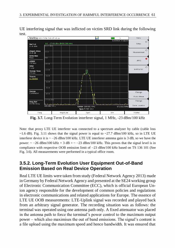
3. EXPERIMENTAL INVESTIGATION OF HARMFUL INTERFERENCE OCCURRENCE 61
UE interfering signal that was inflicted on victim SRD link during the following
test.
Fig. 3.7. Long-Term Evolution interferer signal, 1 MHz, -23 dBm/100 kHz
Note: that proxy LTE UE interferer was connected to a spectrum analyzer by cable (cable loss
~1.6 dB). Fig. 3.11 shows that the signal power is equal to ~27.7 dBm/100 kHz, so in LTE UE
interferer device it is ~ –26 dBm/100 kHz. LTE UE interferer antenna gain is 3 dB, so we have the
power: ~ –26 dBm/100 kHz + 3 dB = ~ –23 dBm/100 kHz. This proves that the signal level is in
compliance with respective OOB emission limit of –23 dBm/100 kHz based on TS 136 101 (See
Fig. 3.6). All measurements were performed in a typical office room.
3.5.2. Long-Term Evolution User Equipment Out-of-Band Emission Based on Real Device Operation
Real LTE UE limits were taken from study (Federal Network Agency 2013) made
in Germany by Federal Network Agency and presented at the SE24 working group
of Electronic Communication Committee (ECC), which is official European Un-
ion agency responsible for the development of common policies and regulations in electronic communications and related applications for Europe. The essence of
LTE UE OOB measurements: LTE-Uplink signal was recorded and played back
from an arbitrary signal generator. The recording situation was as follows: the terminal was operated using one antenna path only. A fixed attenuator was placed
in the antenna path to force the terminal’s power control to the maximum output
power – which also maximises the out of band emissions. The signal’s content is a file upload using the maximum speed and hence bandwidth. It was ensured that

62 3. EXPERIMENTAL INVESTIGATION OF HARMFUL INTERFERENCE OCCURRENCE
the terminal was the only one associated with the serving base station at that mo-
ment. Measurements were conducted in Munich, Germany in the measurement
laboratories of the monitoring stations of Federal Network Agency during April
and July 2012. Following Fig. 3.8 shows the RMS-spectrum for signal UE1 using an RBW of 100 kHz.
Fig. 3.8. Spectrum for User Equipment1 signal (upper sideband only)
(Federal Network Agency 2013)
Like in 3.5.1 paragraph, the proxy LTE UE interferer was configured to ra-
diate the equivalent 1 MHz “channel” that spans the SRD Rx channel and the
power level directly corresponding to the Fig. 3.8. LTE UE interferer was set to ~ –46 dBm/100 kHz.
3.5.3. Results of Investigation of Minimum Carrier-to-Interference Ratio requirement for Short-Range Devices
During the first measurement the proxy LTE UE interferer was brought gradually
toward the SRD Rx, while monitoring the packet flow on victim link and trying to establish possible interruption. The duration of the measurements was 5 minutes
and average values were calculated. The following tables show the results obtained.
Results with LTE UE OOB based on TS 136 101 recommendation (LTE UE inter-
ferer’s in-channel power of -23 dBm/100 kHz) (see Table 3.6 and Table 3.7).
Table 3.6. Measurements results with Semtech, Long-Term Evolution signal according
TS 136 101 limit
1, 2Separation distance, m C, dBm I, dBm C/I, dB
9 –92 –104 12
4 –72 –85 13
Note1: Test criterion for the normal Rx operation – PER not more than 10 %. Note2: Distance when connection lost between SRD Tx and Rx.
SRD frequency = 868.1 MHz

3. EXPERIMENTAL INVESTIGATION OF HARMFUL INTERFERENCE OCCURRENCE 63
Table 3.7. Measurements results with Analog Devices, Long-Term Evolution signal ac-
cording TS 136 101 limit
1, 2Separation distance, m C, dBm I, dBm C/I, dB
8 –94 –101 7
3 –72 –82 10
Note1: Test criterion for the normal Rx operation – PER not more than 10 %.
Results with LTE UE OOB based on real device operation (LTE UE inter-
ferer’s in-channel power level –46 dBm/100 kHz) (see Table 3.8 and Table 3.9).
Table 3.8. Measurements results with Semtech, Long-Term Evolution signal according real device operation
1, 2Separation distance, m C, dBm I, dBm C/I, dB
4 –92 –103 11
1.5 –72 –83 11
Note1: Test criterion for the normal Rx operation – PER not more than 10 %.
Table 3.9. Measurements results with Analog Devices, Long-Term Evolution signal ac-
cording real device operation
1, 2Separation distance, m C, dBm I, dBm C/I, dB
3 –94 –101 7
1.5 –72 –83 11
Note1: Test criterion for the normal Rx operation – PER not more than 10 %.
We can verify these results with FSL formula:
),m,log(20)GHz,log(205.32 dfPL (3.1)
were PL – path loss in dB; f – frequency in GHz; d – distance in meters. The factor before distance logarithm is called path loss exponent γ. In the
study of wireless communications (Goldsmith 2005), path loss can be represented
by the path loss exponent γ, whose value is normally in the range of 2 to 4 (where
2 is for propagation in free space ( ),log(102 md ), 4 is for relatively lossy envi-
ronments. In some environments, such as buildings, stadiums and other indoor
environments, the path loss exponent γ can reach values in the range from 1.6 to
6.5 (Goldsmith 2005).

64 3. EXPERIMENTAL INVESTIGATION OF HARMFUL INTERFERENCE OCCURRENCE
In this study we can’t use standard path loss exponent γ = 2, because all
measurements were done in obstructed building. All measurements were per-
formed in a typical office room with many reflecting and scattering objects. In
this instance path loss exponent γ = 5 was chosen. Then path loss PL formula:
).m,log(50)GHz,log(205.32 dfPL (3.2)
With this PL formula we can verify signal path losses during the measure-
ments. The measurements results verification with path loss formula, when Path Loss exponent γ = 5 in the following Table 3.10.
Table 3.10. Path Loss calculations
Distance, m Path Losses, dB
Path Loss exponent γ = 5
Free Space Losses, dB
Path Loss exponent γ =
2
1 31 31
2 46 37
3 55 41
4 61 43
5 66 45
6 70 47
7 74 48
8 76 49
9 79 50
The following Tables 3.11 and 3.12 show the comparison between measured
C/I and calculated C/I parameters. Path Loss calculated with assumption that Path
Loss exponent γ = 5 (See Table 3.10). Results with LTE UE OOB based on TS 136 101 limits (LTE UE interferer’s in-channel power –23 dBm/100 kHz) (see Ta-
ble 3.11).
Table 3.11. The comparison of Carrier-to-Interference parameter
Practical measurements conducted using Semtech SRD device 1, 2Separation
distance, m C, dBm I, dBm C/I, dB
1C/I calculated with PL
formula, dB
9 –92 –104 12 10
4 –72 –85 13 12
Practical measurements conducted using Analog Devices SRD device
8 –94 –101 7 5
3 –72 –82 10 6
Note1: C/I calculated = –23 dBm/100 kHz – Path Loss at X distance – C, dBm.

3. EXPERIMENTAL INVESTIGATION OF HARMFUL INTERFERENCE OCCURRENCE 65
Results with LTE UE OOB based on real device measured limits (LTE UE
interferer’s in-band power –46 dBm/100 kHz) (see Table 3.12).
Table 3.12. The comparison of Carrier-to-Interference parameter II
Practical measurements conducted using Semtech SRD device
1, 2Separation
distance, m C, dBm I, dBm C/I, dB
1C/I calculated with PL
formula, dB
4 –92 –103 11 15
1.5 –72 –83 11 14
Practical measurements conducted using Analog Devices SRD device
3 –94 –101 7 7
1.5 –72 –83 11 14
Note1: C/I calculated = –23 dBm/100 kHz – Path Loss at X distance – C, dBm. Path Loss expo-
nent γ = 5 (See Table 3.10).
The Tables 3.11 and 3.12 show that required protection criteria C/I between
LTE UE Tx and SRD Rx varies from 7 dB to 13 dB taking into account that LTE UE signal is according to TS 136 101 limits.
Required protection criteria C/I between LTE UE Tx and SRD Rx varies
from 7 dB to 11 dB taking into account that LTE UE signal is according to real device operation.
The identified required protection criterias C/I were verified using theoretical
analysis by performing calculations using Free space radio propagation model
with the adjusted path loss exponent γ from 2 to 5 taking into account that all measurements were conducted in a typical office room with many reflecting, dif-
fracting and scattering objects (considered as relatively lossy environment). The
uncertainty of all measurements is less than ±5%.
3.6. Practical Interference Measurements:
Investigation of Minimum Separation Distance between Long-Term Evolution Transmitter and Short-Range Devices Receiver
The measurement set-up using two SRD devices is shown in Fig. 3.9. Among the SRD equipment is set –94 dBm signal strength according to Fig. 3.4. The LTE
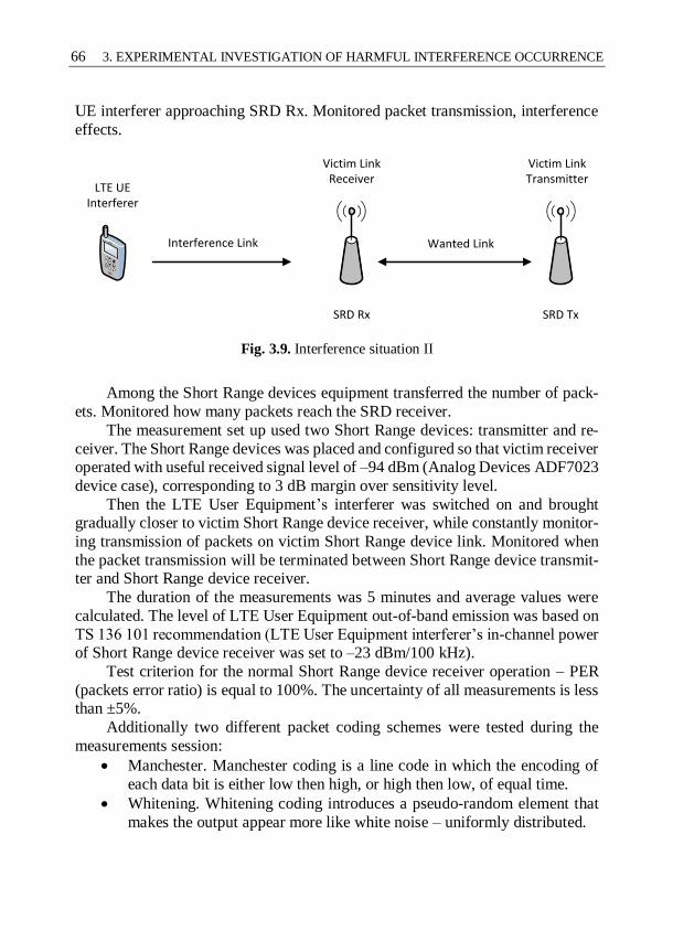
66 3. EXPERIMENTAL INVESTIGATION OF HARMFUL INTERFERENCE OCCURRENCE
UE interferer approaching SRD Rx. Monitored packet transmission, interference
effects.
Victim Link Receiver
Victim Link Transmitter
SRD Rx SRD Tx
Wanted Link
LTE UE Interferer
Interference Link
Fig. 3.9. Interference situation II
Among the Short Range devices equipment transferred the number of pack-
ets. Monitored how many packets reach the SRD receiver.
The measurement set up used two Short Range devices: transmitter and re-
ceiver. The Short Range devices was placed and configured so that victim receiver operated with useful received signal level of –94 dBm (Analog Devices ADF7023
device case), corresponding to 3 dB margin over sensitivity level.
Then the LTE User Equipment’s interferer was switched on and brought gradually closer to victim Short Range device receiver, while constantly monitor-
ing transmission of packets on victim Short Range device link. Monitored when
the packet transmission will be terminated between Short Range device transmit-ter and Short Range device receiver.
The duration of the measurements was 5 minutes and average values were
calculated. The level of LTE User Equipment out-of-band emission was based on
TS 136 101 recommendation (LTE User Equipment interferer’s in-channel power of Short Range device receiver was set to –23 dBm/100 kHz).
Test criterion for the normal Short Range device receiver operation – PER
(packets error ratio) is equal to 100%. The uncertainty of all measurements is less than ±5%.
Additionally two different packet coding schemes were tested during the
measurements session:
Manchester. Manchester coding is a line code in which the encoding of
each data bit is either low then high, or high then low, of equal time.
Whitening. Whitening coding introduces a pseudo-random element that
makes the output appear more like white noise – uniformly distributed.

3. EXPERIMENTAL INVESTIGATION OF HARMFUL INTERFERENCE OCCURRENCE 67
The following Fig. 3.10 shows the results obtained.
Victim Link Receiver
Victim Link Transmitter
SRD Rx SRD Tx
Wanted Link
LTE UE Interferer
Interference Link
If Interference Link distance less than ~2.5 m
Connection lost between SRD Tx and SRD Rx
Fig. 3.10. Interference measurements
The test revealed that the LTE UE interferer close to the SRD Rx distance of less than ~ 2.5 m severs the link between the SRD Tx and SRD Rx.
It was later calculated percentage of packets received at distances greater than
2.5 m. Packet reception is calculated as follows:
%100RP
RP100
received
interfered ratioRP , (3.2)
where RPratio – ratio of successfully received packets, RPinterfered – number of inter-fered packets, RPreceived – number of successfully received packets.
Each measurement was sent 1000 packets and monitored how many of them
came to the SRD Rx. Semtech SX1231 transceiver packages might code two ways - Manchester and Whitening. Packages were sent in 2.7 m, 5 m and 7 m distances.
The following Table 3.13 shows the results using coding methods.
Table 3.13. Calculation of received packets
Distance between LTE UE interferer and
SRD Rx, m
Received packets, %
Manchester
coding
Whitening
coding
2.7 58 53
5 96 74
7 97 96

68 3. EXPERIMENTAL INVESTIGATION OF HARMFUL INTERFERENCE OCCURRENCE
In Table 3.13 we see the distribution of received packets, depending on the
distance to the LTE UE interferer and coding algorithm. When the distance is
greater than 5, the interference effect nearly disappears. It appears that the Man-
chester algorithm is more resistant to interference comparing with Whitening cod-ing.
Manchester coding is one of the most common data coding methods used
today. Similar to BiPhase, Manchester coding provides a means of adding the data rate clock to the message to be used on the receiving end. Also Manchester pro-
vides the added benefit of always yielding an average DC level of 50%.
Whitening is so named because it introduces a pseudo-random element that makes the output appear more like white noise uniformly distributed. Whitening
is typically implemented by using a maximal Linear-Feedback Shift Register
(LFSR) to generate a repeating, pseudo-random pattern of bits that are XOR with
the input data. Since XOR is reversible, the receiver can remove the noise from the data with its own LFSR that is synced to the transmitter.
3.7. Comparison of Practical Interference Measurements with other Actual Studies
3.7.1. Comparison of minimum Carrier-to-Interference Ratio Requirement for Short-Range Devices with other Actual Studies
All material introduced in Chapter 3 of this dissertation was formed and presented as three presentations in Denmark (Copenhagen) and Germany (Karlsruhe and
Berlin) as a representative of Communication Regulatory Authority of the Repub-
lic of Lithuania at the SE24 working group of Electronic Communication Com-mittee (ECC), which is official European Union agency responsible for the devel-
opment of common policies and regulations in electronic communications and
related applications for Europe. After this work the official Electronic Communi-
cation Committee report was published by supporting European Commission (EC) mandate regarding the electromagnetic compatibility problems in 790–
862 MHz LTE frequency band.
Other European countries also contributed to this work. The similar meas-urement study (Federal Network Agency 2013) made in Germany by Federal Net-
work Agency and presented at the SE24 working group of Electronic Communi-
cation Committee (ECC). Measurements were conducted in Munich, Germany in the measurement laboratories of the monitoring stations of Federal Network
Agency during April and July 2012. The results of conducted measurements in

3. EXPERIMENTAL INVESTIGATION OF HARMFUL INTERFERENCE OCCURRENCE 69
Munich, Germany can be compared with the measurements results revealed in
Chapter 3 of this dissertation.
In the Germany’s study two different types (receiver category 1 and 2) of
SRD receivers were investigated, overall three main types of SRD radio receivers are classified (see Table 3.14).
Table 3.14. Categories of radio receivers
Receiver category Risk assessment of receiver perfor-
mance
1
Highly reliable SRD communication
media; e.g. serving human life inherent
systems (may result in a physical risk to
a person)
2
Medium reliable SRD communication media e.g. causing inconvenience to
persons, which cannot simply be over-
come by other means
3
Standard reliable SRD communication
media e.g. Inconvenience to persons,
which can simply be overcome by other
means (e.g. manual)
In the Germany’s study is the summarised information regarding the protection ratio C/I of SRD receivers taking into account different LTE UE operation and
different frequency offset between LTE UE Tx and SRD Rx.
Fig. 3.11. Comparison of median protection ratios for all interfering signals at low level,
Rx cat. 1 (Federal Network Agency 2013)

70 3. EXPERIMENTAL INVESTIGATION OF HARMFUL INTERFERENCE OCCURRENCE
Fig. 3.11 identifies the protection ratio C/I of SRD receivers Cat. 1 taking
into account five different LTE UE operation and different frequency offset be-
tween LTE UE Tx and SRD Rx. SRD Rx Cat. 1 – the measurements performed
on wireless audio devices from category 1.
Fig. 3.12. Comparison of median protection ratios for all interfering signals at low level,
Rx cat. 2 (Federal Network Agency 2013)
Fig. 3.12 identifies the protection ratio C/I of SRD receivers Cat. 2 taking
into account five different LTE UE operation and different frequency offset be-tween LTE UE Tx and SRD Rx. SRD Rx Cat. 2 – the measurements performed
on Hearing aids and tourguide systems from category 2.
The more detailed information regarding the five different interfering LTE signals can be seen in the Table 3.15.
LTE UE1 signal is closest to the measurements performed in section 3.5.
LTE UE1 signal was recorded and played back from an arbitrary signal generator.
The recording situation was as follows: the terminal was operated using one an-tenna path only. A fixed attenuator was placed in the antenna path to force the
terminal’s power control to the maximum output power – which also maximises
the out of band emissions. The signal’s con-tent is a file upload using the maxi-mum speed and hence bandwidth. It was ensured that the terminal was the only
one associated with the serving base station at that moment.
Returning to Fig. 3.11 and Fig. 3.12 most interesting cases are when LTE UE1 signal is used and frequency offset is 0 MHz – the same situation as in section
3.5 (see Tables 3.11 and 3.12). The measurements performed in Chapter 3 with
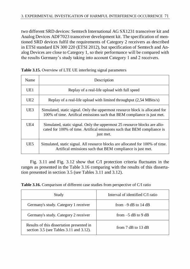
3. EXPERIMENTAL INVESTIGATION OF HARMFUL INTERFERENCE OCCURRENCE 71
two different SRD devices: Semtech International AG SX1231 transceiver kit and
Analog Devices ADF7023 transceiver development kit. The specification of men-
tioned SRD devices fulfil the requirements of Category 2 receivers as described
in ETSI standard EN 300 220 (ETSI 2012), but specification of Semtech and An-alog Devices are close to Category 1, so their performance will be compared with
the results Germany’s study taking into account Category 1 and 2 receivers.
Table 3.15. Overview of LTE UE interfering signal parameters
Name Description
UE1 Replay of a real-life upload with full speed
UE2 Replay of a real-life upload with limited throughput (2,54 MBits/s)
UE3 Simulated, static signal. Only the uppermost resource block is allocated for
100% of time. Artifical emissions such that BEM compliance is just met.
UE4 Simulated, static signal. Only the uppermost 25 resource blocks are allo-cated for 100% of time. Artifical emissions such that BEM compliance is
just met.
UE5 Simulated, static signal. All resource blocks are allocated for 100% of time.
Artifical emissions such that BEM compliance is just met.
Fig. 3.11 and Fig. 3.12 show that C/I protection criteria fluctuates in the
ranges as presented in the Table 3.16 comparing with the results of this disserta-tion presented in section 3.5 (see Tables 3.11 and 3.12).
Table 3.16. Comparison of different case studies from perspective of C/I ratio
Study Interval of identified C/I ratio
Germany's study. Category 1 receiver from –9 dB to 14 dB
Germany's study. Category 2 receiver from –5 dB to 9 dB
Results of this dissertation presented in
section 3.5 (see Tables 3.11 and 3.12). from 7 dB to 13 dB

72 3. EXPERIMENTAL INVESTIGATION OF HARMFUL INTERFERENCE OCCURRENCE
Table 3.16 shows the summarised results and identifies that the results of this
dissertation presented in section 3.5 (see Tables 3.11 and 3.12) are in compliance
with Germany’s study taking into account the results with SRD receivers in Cat-
egory 1 and 2. The differences between these results can be found by analysing the protection criteria used in both studies:
a) Germany’s study used the protection criteria – ETSI TS 102 192 (ETSI
2004) standard considers a professional microphone transmission as interference-free, if the unweighted AF-SINAD (Audio Frequency – Signal in Noise and Dis-
tortion) is at least 30 dB. This interference criterion (SINAD is reduced to 30 dB
in the presence of an interferer) is applied in the measurements at hand, since all receivers are classified as intended for professional use. Beyond the practical rea-
son that no easy method exists to measure the bit error rate for those systems, the
following effects apply in the presence of interference (at the 30 dB limit):
The SINAD starts to drop rapidly which – vice versa – means that the
bit error rate climbs up in a steep ascent.
The audio signal starts to sound chopped; the amplitude starts to fluc-
tuate.
The audio signal starts to crackle and rattle.
b) Results of this dissertation presented in section 3.5 (see Tables 3.11 and
3.12) the protection criteria was use – test criterion for the normal Rx operation – PER (packets error ratio) not more than 10 %.
The protection criteria used in a) case identifies more sensual interference
influence to SRD receivers, since only audio devices were used in Germany’s study. The protection criteria used in b) case identifies more absolute interference
influence to SRD receivers, since only generic (non audio) SRD devices were in-
vestigated.
3.7.2. Comparison of Minimum Separation Distance Between Long-Term Evolution Transmitter and Short-Range Devices with other Actual Studies
All material introduced in Chapter 3 of this dissertation was formed and presented
as three presentations in Denmark (Copenhagen) and Germany (Karlsruhe and Berlin) as a representative of Communication Regulatory Authority of the Repub-
lic of Lithuania at the SE24 working group of Electronic Communication Com-
mittee (ECC), which is official European Union agency responsible for the devel-
opment of common policies and regulations in electronic communications and related applications for Europe. After this work the official Electronic Communi-
cation Committee report was published by supporting European Commission
(EC) mandate regarding the electromagnetic compatibility problems in 790–
862 MHz LTE frequency band.

3. EXPERIMENTAL INVESTIGATION OF HARMFUL INTERFERENCE OCCURRENCE 73
Other European countries also contributed to this work. The similar measure-
ment study (ERA Technology 2011) made in United Kingdom by ERA Technol-
ogy company requested by Ofcom (Ofcom is the communications regulator in the
UK) and presented at the SE24 working group of Electronic Communication Committee (ECC). The results of conducted measurements in UK can be com-
pared with the measurements results revealed in Chapter 3 of this dissertation.
In the UK’s study three different types of SRD receivers were investigated, overall three main types of SRD radio receivers are classified as described in Ta-
ble 3.14. The main measurement set-up: the wanted SRD signal was generated
from the SRD transmitting device which was attenuated, where necessary, to give the required wanted signal level at the receiver.
The unwanted LTE UE signal was radiated inside an anechoic chamber. The
level of the LTE interference was increased until the required interference crite-
rion was achieved. The received signal level was measured directly by substituting the SRD re-
ceiver with a 0 dBi mini-biconical antenna connected to a spectrum analyser, the
antenna gain and cable loss have been taken into account in the measurements. Three different cases for LTE UE where performed during the measurements:
LTE uses 1 RB (minimum interference case).
LTE uses 25 RB (average interference case).
LTE uses 50 RB (maximum interference case).
LTE UE OOB levels are in compliance with ECC/DEC(09)03. The OOB lev-
els are the function of frequency, relative to the edge of a block of spectrum that is licensed to an operator. It consists of in-block and out-of-block components
which specify the permitted emission levels over frequencies inside and outside
the licensed block of spectrum respectively. The seven different receivers of Short
Range devices receivers were tested during the measurements session:
Social alarm.
Medical device (with 0 dBi antenna gain).
Telemetry device, smart meter.
Radio microphone.
Intruder alarm.
Headphones.
In the UK’s study the summarised information regarding the separation dis-
tance between LTE Tx and SRD Rx taking into account different LTE User Equip-
ment operation and different categories SRD Rx. Fig. 3.13 summarises UK’s study and identifies that separation distance be-
tween LTE UE using 50 RB and SRD Rx operating 10 dB above minimum sensi-
tivity is between 11.7 m and 49.7 m according to SRD Rx category.

74 3. EXPERIMENTAL INVESTIGATION OF HARMFUL INTERFERENCE OCCURRENCE
Fig. 3.13. Protection distances for simulated Long-Term Evolution with 50 RB:
wanted level 10 dB above minimum sensitivity (ERA Technology 2011)
Table 3.17 shows the summarised results of UK’s study comparing with the
results of this dissertation presented in section 3.6.
Table 3.17. Comparison of different case studies from perspective of separation distance
Study Identified separation distance
UK’s study from 11.7 m to 49.7 m
Results of this dissertation presented in
section 3.6 average distance of 2.5 m
The differences between these results can be found by analysing the meas-
urement set-up in both studies:
a) The measurements of UK’s study were performed inside an anechoic chamber. Measurements results of this dissertation presented in section
3.6 of this dissertation were collected in a standard office room.
b) The wanted level of SRD Rx was set to 10 dB above minimum sensitivity
during the measurements in UK’s study. The wanted level of SRD Rx was set to 3 dB above minimum sensitivity during the measurements per-
formed in section 3.6 of this dissertation.

3. EXPERIMENTAL INVESTIGATION OF HARMFUL INTERFERENCE OCCURRENCE 75
These differences between mentioned studies don’t let to compare results di-
rectly, but show a logical conformity between them. The average separation dis-
tance of 2.5 m can be validated by lower wanted signal level and measurement
environment.
3.8. Conclusions of Chapter 3
1. The investigation of minimum C/I parameter requirement for SRD de-
vices identified that required protection criteria C/I between LTE UE Tx
and SRD Rx varies from 7 dB to 13 dB taking into account that LTE UE signal is according to TS 136 101 limits. Required protection criteria C/I
between LTE UE Tx and SRD Rx varies from 7 dB to 11 dB taking into
account that LTE UE signal is according to real device operation. The
uncertainty of all measurements is less than ±5%. 2. The identified required protection criterias C/I were verified using theo-
retical analysis by performing calculations using Free space radio prop-
agation model. The results of the measurements identified that the path loss exponent γ have to be adjusted from 2 to 5 in order to take into ac-
count that the measurements were conducted in a typical office room
with many reflecting, diffracting and scattering objects (considered as relatively lossy environment).
3. The investigation of minimum separation distance between LTE Tx and
SRD Rx identified that the LTE UE interferer close to the SRD Rx dis-
tance of less than ~ 2.5 m severs the link between the SRD Tx and SRD Rx. Additional analysis concluded that the Manchester algorithm is more
resistant to interference comparing with Whitening coding.
4. As an overall conclusion, it may be recommended that the limits of LTE UE OOB emissions may need to be revised in order to ensure the reason-
able degree of adjacent band co-existence with SRDs.

77
General Conclusions
1. Evaluation of possible electromagnetic compatibility (EMC) problems in
the 790–862 MHz frequency band concluded that LTE networks based
on OFDM can produce harmful level of out of band emissions to neigh-
bour radio systems as digital terrestrial TV broadcasting in the frequency
range 470–790 MHz, aeronautical radio navigation systems operating in
the 638–862 MHz frequency band and Short-Range Devices operating
in the frequency band 862–880 MHz. The most sensitive case is the EMC
between LTE networks and SRD due the huge lack of information re-
garding SRD and LTE electromagnetic compatibility and due to ever growing density of SRD and uncontrolled operation behaviour of SRD.
2. Theoretical analysis identified that FBMC technique is more spectrum
efficient – Out-of-Band emissions are approximately 20 dB less compar-
ing to OFDM. 3. Performed simulations with hypothetical LTE networks using OFDM
and FBMC identified the significantly higher level of probability of in-
terference using FBMC than OFDM technique. It is concluded that LTE systems with FBMC technique can reduce the probability of interference
more than 2.5 times regarding the separation distance. Confidence inter-
val of all simulations is 95 %. In most crucial situation (separation dis-

78 GENERAL CONCLUSIONS
tance equals 10 m) the Short Range Devices which correspond to An-
nex 1 and Annex 7 could co-exist in the same room assumption if FBMC
emission mask would use in LTE mobile networks (with assumption that probability of interference (PoI) less than 5 % is considered like a suffi-
cient level). When the separation distance is longer than 50 m, the inter-
ference effect is validated as disappeared regarding all investigated SRD types using FBMC.
4. The results of the measurements identified that the minimum C/I param-
eter for SRD devices have to be higher than 7 dB taking into account that
LTE UE signal is according to TS 136 101 limits. The results of the measurements identified that the minimum C/I parameter for SRD de-
vices have to be higher than 7 dB taking into account that LTE UE signal
is according to real device operation. The uncertainty of all measure-ments is less than ±5%.
5. The results of the measurements identified that the path loss exponent γ
of Free space radio propagation model have to be equal 5 in order to reflect the situation that the measurements were conducted in a typical
office room.
79
References
Bahai, A., Saltzberg, B. & Ergen, M., 2004. Multi-carrier digital communications:
theory and applications of OFDM, Springer Science & Business Media.
Bahai, A. R. S. & Saltzberg, B. R., 2006. Multi-Carrier Digital Communications:
Theory and Applications of OFDM, Springer Science & Business Media.
Begovic, P., Behlilovic, N. & Avdic, E., Applicability evaluation of Okumura,
Ericsson 9999 and winner propagation models for coverage planning in 3.5 GHZ
WiMAX systems, pp. 256–260.
Bellanger, M., 2010. FBMC physical layer: a primer. PHYDYAS, January, pp. 1–
31.
Bellanger, M., 2012. FS-FBMC: A flexible robust scheme for efficient multicarrier
broadband wireless access. In 2012 IEEE Globecom Workshops. IEEE, pp. 192–
196.
Boudreau, G., Panicker, J. & Vrzic, S., 2009. Interference coordination and
cancellation for 4G networks. IEEE Communications Magazine, 47(4), pp. 74–81.
Cambini, C. & Garelli, N., 2011. Evaluation of the opportunity cost of the spectrum:
Application to the digital dividend. Telecommunications Policy, 35(7), pp. 633–649.
CEPT, 2009a. CEPT Report 29-Guideline on cross border coordination issues
between mobile services in one country and broadcasting services in another
country.
80 REFERENCES
CEPT, 2009b. CEPT Report 31-Frequency (channelling) arrangemen ts for the
790–862 MHz band.
CEPT, 2009c. CEPT Report 32-The identification of common a nd minimal (least
restrictive) technical conditions for 790–862 MHz for the digital dividend in the
European Union.
CEPT, 2010. ECC Report 148-Measurements on the performance of dvb-t receivers
in the presence of interference from the mobile service (especially from LTE).
CEPT, 2014. ECC Report 207-Adjacent band co- existence of SRDs in the band 863-
870 MHz in light of the LTE usage below 862 MHz.
Chandhar, P., Ghosh, P. & Das, S.S., 2014. Performance analysis of co-channel
deployment of femtocells with power control in 4G networks. In 2014 Twentieth
National Conference on Communications (NCC). IEEE, pp. 1–6.
Chang, P. et al., 2010. Interference Analysis of TD-LTE and TD-SCDMA System
Coexistence. In 2010 Second International Conference on Networks Security,
Wireless Communications and Trusted Computing. IEEE, pp. 77–80.
Chee, K. L. & Kürner, T., 2010. Effect of terrain irregularities and clutter
distribution on wave propagation at 3.5 GHz in suburban area. Proceedings of the
Fourth European Conference on Antennas and Propagation, pp. 1–5.
Cisco, 2015. Cisco Visual Networking Index: Global Mobile Data Traffic Forecast
Update, 2015–2020 White Paper.
Datta, R. et al., 2011. Flexible multicarrier PHY design for cognitive radio in White
Space. 2011 6th International ICST Conference on Cognitive Radio Oriented
Wireless Networks and Communications (CROWNCOM), 248454(248454),
pp.141–145.
Doucet, A., Freitas, N. de & Gordon, N., 2013. Sequential Monte Carlo Methods in
Practice, Springer Science & Business Media.
ECC, 2009. ECC/DEC/(09)03-Harmonised conditions for mobile/fixed
communications networks (MFCN) operating in the band 790–862 MHz.
ECO, 2016. European Frequency Information System.
ECO, 2010. SEAMCAT Handbook.
ERA Technology, 2011. Investigation on the receiver characteristics of SRD
equipment in the 863 - 870 MHz band. , p. 110.
ERC, 2015. ERC Recommendation 70-03.
ETSI, 2012. EN 300 220-1- Electromagnetic compatibility and Radio spectrum
Matters (ERM); Short Range Devices (SRD); Radio equipment to be used in the
25 MHz to 1 000 MHz frequency range with power levels ranging up to 500 mW.
REFERENCES 81
ETSI, 2008. EN 301 357-2 - Electromagnetic compatibility and Radio spectrum
Matters (ERM); Cordless audio devices in the range 25 MHz to 2 000 MHz; Part
2: Harmonized EN covering essential requirements of article 3.2 of the R&TTE
Directive.
ETSI, 2004. ETSI TS 102 192-E lectromagnetic compatibility and Radio spectrum
Matters (ERM); International Technical Characteristics and Test Methods.
ETSI, 2011a. TS 136 101 - V10.3.0 - LTE; Evolved Universal Terrestrial Radio
Access (E-UTRA); User Equipment (UE) radio transmission and reception.
ETSI, 2011b. TS 136 141 - LTE; Evolved Universal Terrestrial Radio Access (E-
UTRA); Base Station (BS) conformance testing., pp. 1–187.
Ettus Research, 2013. Ettus Research WBX-40 datsheet.
European Comission, 2010. European Commission Decision of 6 May 2010 on
harmonised technical conditions of use in the 790–862 MHz frequency band for
terrestrial systems capable of providing electronic communications services in EU.
Farhang-Boroujeny, B., 2008. A Square-Root Nyquist (M) Filter Design for Digital
Communication Systems. IEEE Transactions on Signal Processing, 56(5), pp.
2127–2132.
Farhang-Boroujeny, B., 2011a. OFDM Versus Filter Bank Multicarrier. IEEE
Signal Processing Magazine, 28(3), pp. 92–112.
Farhang-Boroujeny, B., 2011b. Signal Processing Techniques for Software Radios,
Lulu.
Farhang-Boroujeny, B., 2009. Solution to Spectrum Sensing and Data Transmission
in Cognitive Radio Networks.
Federal Network Agency, 2013. Measurements on the impact of LTE800-User
Equipment on wireless microphones, hearing aids and tourguide systems in the
frequency range 863–865 MHz, Germany.
Fishman, G., 2013. Monte Carlo: Concepts, Algorithms, and Applications, Springer
Science & Business Media.
Gao, J., Chase, K. W. & Magleby, S. P., A New Monte Carlo Simulation Method
for Tolerance Analysis of Kinematically Constrained Assemblies.
Goldsmith, A., 2005. Wireless communications, Cambridge University Press.
Grandell, K. J., 2001. Indoor antennas for WCDMA systems. In 11th International
Conference on Antennas and Propagation (ICAP 2001). IEEE, pp. 208–211.
Griffiths, H. et al., 2013. Challenge problems in spectrum engineering and
waveform diversity. In 2013 IEEE Radar Conference (RadarCon13). IEEE, pp. 1–
5.
82 REFERENCES
Himayat, N. et al., 2010. Interference management for 4G cellular standards
[WIMAX/LTE UPDATE. IEEE Communications Magazine, 48(8), pp. 86–92.
Huang, J. et al., 2011. Progressive Inter-Carrier Interference Equalization for OFDM
Transmission Over Time-Varying Underwater Acoustic Channels. IEEE Journal of
Selected Topics in Signal Processing, 5(8), pp. 1524–1536.
Ihalainen, T. et al., 2007. Channel Equalization in Filter Bank Based Multicarrier
Modulation for Wireless Communications. EURASIP Journal on Advances in
Signal Processing, 2007(1), pp. 1–18.
International Telecommunication Union, 2012. Digital Dividend: Insights for
Spectrum Decisions. White paper. pp. 1–61.
ITU, 2006. Final Acts of the Regional Radiocommunication Conference for
planning of the digital terrestrial broadcasting service in parts of Regions 1 and 3,
in the frequency bands 174–230 MHz and 470–862 MHz (RRC-06).
International Telecommunication Union, 2012. Radio Regulations.
Karimi, H. R. et al., 2010. European Harmonized Technical Conditions and Band
Plans for Broadband Wireless Access in the 790–862 MHz Digital Dividend
Spectrum. In 2010 IEEE Symposium on New Frontiers in Dynamic Spectrum
(DySPAN). IEEE, pp. 1–9.
Kollár, Z. & Horváth, P., 2012. PAPR reduction of FBMC by clipping and its
iterative compensation. Journal of Computer Networks and Communications, 2012.
Kollár, Z., Péceli, G. & Horváth, P., 2011. Iterative decision feedback equalization
for FBMC systems. Proceedings of IEEE First International Conference on
Advances in Cognitive Radio,(COCORA 2011), (c), pp. 31–35.
Kubota, S., Kato, S. & Feher, K., 1992. Inter-channel interference cancellation
technique for CDMA mobile/personal communication systems. In [1992
Proceedings] The Third IEEE International Symposium on Personal, Indoor and
Mobile Radio Communications. IEEE, pp. 112–117.
Kurosaki, S. et al., 2002. SDM-COFDM scheme using feed-forward inter-channel
interference canceller for broadband mobile communications. In Vehicular
Technology Conference. IEEE 55th Vehicular Technology Conference. VTC Spring
2002 (Cat. No.02CH37367). IEEE, pp. 1079–1083.
Lambert M. S., Miriam T. Timpledon, S.F.M., 2010. Nyquist Rate, Betascript
Publishing.
Lélé, C. et al., 2008. Channel estimation methods for preamble-based OFDM/OQAM modulations. European Transactions on Telecommunications,
19(7), pp. 741–750.
Li, W. et al., 2012. Performance and Analysis on LTE System under Adjacent

REFERENCES 83
Channel Interference of Broadcasting System. In 2012 IEEE 12th International
Conference on Computer and Information Technology. IEEE, pp. 290–294.
Loulou, A. & Renfors, M., 2013. Effective schemes for OFDM sidelobe control in
fragmented spectrum use. In 2013 IEEE 24th Annual International Symposium on
Personal, Indoor, and Mobile Radio Communications (PIMRC). IEEE, pp. 471–
475.
Maqbool, M., Coupechoux, M. & Godlewski, P., 2008. Comparison of Various
Frequency Reuse Patterns for WiMAX Networks with Adaptive Beamforming. In
VTC Spring 2008 - IEEE Vehicular Technology Conference. IEEE, pp. 2582–2586.
Medeisis, A. & Kajackas, A., 2000. On the use of the universal Okumura-Hata
propagation prediction model in rural areas. In VTC2000-Spring. 2000 IEEE 51st
Vehicular Technology Conference Proceedings (Cat. No.00CH37026). IEEE, pp.
1815–1818.
Medjahdi, Y., Terre, M., et al., 2011. On spectral efficiency of asynchronous
OFDM/FBMC based cellular networks. 2011 IEEE 22nd International Symposium
on Personal, Indoor and Mobile Radio Communications, 1, pp. 1381–1385.
Medjahdi, Y., Terré, M., et al., 2011. Performance analysis in the downlink of
asynchronous OFDM/FBMC based multi-cellular networks. IEEE Transactions on
Wireless Communications, 10(8), pp. 2630–2639.
Mitra, S. K., 1996. Overlapped block digital filtering. IEEE Transactions on
Circuits and Systems II: Analog and Digital Signal Processing, 43(8), pp. 586–596.
Mitra, S. K. & Kaiser, J. F., 1993. Handbook for Digital Signal Processing, John
Wiley & Sons, Inc.
Modlic, B., Sisul, G. & Cvitkovic, M., Digital dividend 2014; Opportunities for new
mobile services, pp.1–8.
Molisch, A., 2011. Wireless Communications: Principles and Practice, Prentice
Hall.
Osseiran, A. et al., 2014. Scenarios for 5G mobile and wireless communications:
The vision of the METIS project. IEEE Communications Magazine, 52(5).
Ostlin, E., Zepernick, H. M. & Suzuki, H., 2003. Evaluation of the new semi-terrain
based propagation model recommendation ITU-R P.1546. In 2003 IEEE 58th
Vehicular Technology Conference. VTC 2003-Fall (IEEE Cat. No.03CH37484).
IEEE, p. 114–118 Vol.1.
Park, C. J. & Im, G. H., 2004. Efficient DMT/OFDM Transmission With
Insufficient Cyclic Prefix. IEEE Communications Letters, 8(9), pp. 576–578.
Paul, C. R., 2006. Introduction to Electromagnetic Compatibility, John Wiley &
Sons.

84 REFERENCES
Prasad, R., 2004. OFDM for Wireless Communications Systems, Artech House.
Premnath, S. N. et al., 2013. Beyond OFDM: Best-effort dynamic spectrum access
using filterbank multicarrier. IEEE/ACM Transactions on Networking, 21(3), pp.
869–882.
Proakis, J. G., 2003. Wiley Encyclopedia of Telecommunications J. G. Proakis, ed.,
Hoboken, NJ, USA: John Wiley & Sons, Inc.
Proakis, J. G. & Salehi, M., 2008. Digital Communications, McGraw-Hill.
Chang, R., 1966. High-speed multichannel data transmission with bandlimited
orthogonal signals. Bell System Technical Journal, pp. 1775–1796.
Radil, T., Ramos, P. M. & Serra, A.C., 2009. New Spectrum Leakage Correction
Algorithm for Frequency Estimation of Power System Signals. IEEE Transactions
on Instrumentation and Measurement, 58(5), pp. 1670–1679.
Rajabzadeh Oghaz, M. et al., 2014. Sidelobe suppression for non-systematic coded
UW-OFDM in cognitive radio networks. EW2014.
Renfors, M. et al., 2013. On the use of filter bank based multicarrier modulation for
professional mobile radio. In IEEE Vehicular Technology Conference.
Rhee, W. & Cioffi, J. M., 2000. Increase in capacity of multiuser OFDM system
using dynamic subchannel allocation. In VTC2000-Spring. 2000 IEEE 51st
Vehicular Technology Conference Proceedings (Cat. No.00CH37026). IEEE, pp.
1085–1089.
Ringset, V. et al., 2011. Performance of a FilterBank MultiCarrier (FBMC) physical
layer in the WiMAX context, pp. 1–8.
Sadeghi, B., Sabahi, M.F. & Noripoor, J., 2014. Sidelobe Suppression in OFDM
Systems using Suitable Map in Constellation Expansion Method. Majlesi Journal
of Telecommunication Devices, 3(1).
Saltzberg, B., 1967. Performance of an Efficient Parallel Data Transmission System.
IEEE Transactions on Communication Technology, 15(6), pp. 805–811.
Schellmann, M. et al., 2014. FBMC-based air interface for 5G Mobile: Challenges
and proposed solutions. In Proceedings of the 9th International Conference on
Cognitive Radio Oriented Wireless Networks. ICST, pp. 102–107.
Seidenberg, P. et al., 1999. Statistics of the minimum coupling loss in UMTS/IMT-
2000 reference scenarios. In Gateway to 21st Century Communications Village.
VTC 1999-Fall. IEEE VTS 50th Vehicular Technology Conference (Cat.
No.99CH36324). IEEE, pp. 963–967.
Selim, A. & Doyle, L., 2013. Real-time sidelobe suppression for OFDM systems
using advanced subcarrier weighting. In 2013 IEEE Wireless Communications and
Networking Conference (WCNC). IEEE, pp. 4043–4047.

REFERENCES 85
Shaat, M. & Bader, F., 2010. Computationally Efficient Power Allocation
Algorithm in Multicarrier-Based Cognitive Radio Networks: OFDM and FBMC
Systems. EURASIP Journal on Advances in Signal Processing, 2010, pp. 1–14.
Shen, X., 1996. Modelling enhanced spherical diffraction and troposcattering on a
transhorizon path with the aid of the parabolic equation and ray tracing methods. In
IEE Colloquium on Common Modelling Techniques for Electromagnetic Wave and
Acoustic Wave Propagation. IEE, pp. 4–4.
Simon Plass, Armin Dammann, Stefan Kaiser, K.F., 2007. Multi-Carrier Spread
Spectrum 2007, Springer Netherlands.
Siohan, P., Siclet, C. & Lacaille, N., 2002. Analysis and design of OFDM/OQAM
systems based on filterbank theory. IEEE Transactions on Signal Processing, 50(5),
pp. 1170–1183.
Sommer, C. et al., 2011. A computationally inexpensive empirical model of IEEE
802.11p radio shadowing in urban environments. In 2011 Eighth International
Conference on Wireless On-Demand Network Systems and Services. IEEE, pp. 84–
90.
Steendam, H. & Moeneclaey, M., 2000. Sensitivity of orthogonal frequency-
division multiplexed systems to carrier and clock synchronization errors. Signal
Processing, 80(7), pp. 1217–1229.
Toeltsch, M. & Molisch, A. F., 2000. Efficient OFDM transmission without cyclic
prefix over frequency-selective channels. In 11th IEEE International Symposium on
Personal Indoor and Mobile Radio Communications. PIMRC 2000. Proceedings
(Cat. No.00TH8525). IEEE, pp. 1363–1367.
Tse, D. & Viswanath, P., 2005. Fundamentals of Wireless Communication,
Cambridge University Press.
Tureli, U. & Zoltowski, M.D., A high efficiency carrier estimator for OFDM communications. In Conference Record of the Thirty-First Asilomar Conference on
Signals, Systems and Computers (Cat. No.97CB36136). IEEE Comput. Soc, pp.
505–509.
Unser, M., 1999. Splines: a perfect fit for signal and image processing. IEEE Signal
Processing Magazine, 16(6), pp. 22–38.
Vangelista, L. & Laurenti, N., 2001. Efficient implementations and alternative
architectures for OFDM-OQAM systems. IEEE Transactions on Communications,
49(4), pp. 664–675.
Visotsky, E., Kuffner, S. & Peterson, R., On collaborative detection of TV
transmissions in support of dynamic spectrum sharing. In First IEEE International
Symposium on New Frontiers in Dynamic Spectrum Access Networks, 2005.
DySPAN 2005. IEEE, pp. 338–345.
86 REFERENCES
Waldhauser, D. S., 2009. Multicarrier Systems Based on Filter Banks, Shaker.
Zahariadis, T. & Kazakos, D., 2003. (R)evolution toward 4G mobile communication
systems. IEEE Wireless Communications, 10(4), pp. 6–7.
Zakaria, R., 2012. Transmitter and receiver design for inherent interference
cancellation in MIMO filter-bank based multicarrier systems. Paris, CNAM.
Zhang, H. et al., 2010. Spectral efficiency comparison of OFDM/FBMC for uplink
cognitive radio networks. Eurasip Journal on Advances in Signal Processing, 2010.
Zhang, H. Z. H. et al., 2010. Capacity analysis of OFDM / FBMC based Cognitive
Radio networks with estimated CSI. Cognitive Radio Oriented Wireless Networks
& Communications (CROWNCOM), 2010 Proceedings of the Fifth
International Conference on, pp. 1–19.
Zhang Meng et al., 2013. Coexistence studies on the interference performance
between mobile satellite system and LTE network. China Communications, 10(7),
pp. 1–11.
Zhao, Y. & Haggman, S. G., Sensitivity to Doppler shift and carrier frequency errors
in OFDM systems-the consequences and solutions. In Proceedings of Vehicular
Technology Conference - VTC. IEEE, pp. 1564–1568.
Zhu, J. et al., 2007. Multi-Radio Coexistence: Challenges and Opportunities. In
2007 16th International Conference on Computer Communications and Networks.
IEEE, pp. 358–364.
Zhu, X., Shen, L. & Yum, T., 2007. Analysis of Cognitive Radio Spectrum Access
with Optimal Channel Reservation. IEEE Communications Letters, 11(4), pp. 304–
306.

87
List of Publications by the Author on
the Topic of the Dissertation
Papers in the Reviewed Scientific Journals
Stankevičius, E., Zakaria, R., Kazlauskas, S., 2015a. FBMC modulation as a possible co-
existence facilitator for LTE mobile networks in 800 MHz band. IETE Journal of Re-
search, ISSN 0377-2063, Volume: 61, no. 4, p. 417–422. (ISI Web of Science). IF=0.284.
Ancans, G., Stankevičius, E., Bobrovs, V., 2015b. Assessment of DVB-T Compatibility with LTE in Adjacent Channels in 700 MHz Band. Electronics and electrical engineering
= Elektronika ir elektrotechnika. Kaunas: Technologija, ISSN 1392-1215, Vol. 21, no. 4
(2015), p. 73–77. (ISI Web of Science). IF=0.561.
Stankevičius, E., Medeišis, A., Paulikas, Š., Anskaitis, A., 2015c. Electromagnetic com-
patibility problems in LTE mobile networks 800 MHz frequency band. Electronics and
electrical engineering = Elektronika ir elektrotechnika. Kaunas: Technologija, ISSN
1392-1215, Vol. 21, no. 6 (2015), p. 86–89. (ISI Web of Science). IF=0.561.
Stankevičius, E., Oberauskas, Š., 2014. Electromagnetic compatibility studies: LTE BS vs. Aeronautical Radionavigation Services in 694–790 MHz frequency band. Electrical,
Control and Communication Engineering. ISSN 2255-9140, Volume: 6, p. 38–44.
(Google Scholar).
88 LIST OF PUBLICATIONS BY THE AUTHOR ON THE TOPIC OF…
Other Papers
Ancans, G., Stankevičius, E., Bobrovs, V., 2016. Evaluation of LTE700 and DVB-T and
DVB-T2 electromagnetic compatibility for co-channel case. PIERS Proceedings: Pro-
gress in electromagnetics research symposium, Shanghai, China, August 8–11, 2016. Cambridge: The Electromagnetics Academy, ISSN 1559-9450, p. 585–589. (SCOPUS).
Ancans, G., G., Stankevičius, E., Bobrovs, V., Paulikas, Š., 2015d. Evaluation of LTE 700
and DVB-T electromagnetic compatibility in adjacent frequency bands. PIERS Proceed-
ings: Progress in electromagnetics research symposium, Prague, Czech Republic, July 6–
9, 2015. Cambridge: The Electromagnetics Academy, ISSN 1559-9450, p. 585–589.
(SCOPUS).

89
Summary in Lithuanian
Įvadas Problemos formulavimas
Pasaulinė Radijo ryšio konferencija 2007 metais paskyrė vadinamąją „skaitmeninio
dividendo“ 790–862 MHz dažnių juostą antžeminiams mobiliesiems tinklams Regiono 1
(Europa, Afrika, Vidurinieji Rytai) valstybėse nuo 2015 metų. Ši radijo dažnių juosta
galėjo būti pradėta eksploatuoti ir prieš 2015 metus, bet tik laikantis visų Radijo
Reglamento nuostatų (ITU 2012).
2009 metais Regiono 1 valstybės nusprendė sukurti oficialų sprendimą (ECC 2009),
kuris nustatytų orientyrus bendrosioms radijo ryšio naudojimo sąlygoms 790–862 MHz dažnių juostoje diegiant antžeminius mobiliuosius tinklus ir siekiant padėti mobiliojo
ryšio operatoriams kovoti su radijo dažnių trūkumu dėl vis didėjančios mobiliojo ryšio
paklausos (ECC 2009; Chandhar et al. 2014).
Mobiliojo ryšio operatoriai turi išteklių plėsti savo tinklus, tačiau tampa vis
sudėtingiau išvengti trukdžių tarp gretimų radijo stočių, dėl vis didėjančio radijo įrenginių
tankio (Himayat et al. 2010; Boudreau et al. 2009).
Be detalios elektromagnetinio suderinamumo analizės LTE (angl. Long-Term
Evolution) mobiliojo ryšio tinklų nebūtų galima diegti 790–862 MHz dažnių juostoje, dėl
ypač veiksmingų radijo bangų sklidimo ypatybių šioje dažnių juostoje ir žalingos šalutinės
spinduliuotės lygių, kurie sukelia žalingus radijo trukdžius radijo ryšio sistemoms,

90 SUMMARY IN LITHUANIAN
veikiančioms kaimyninėse dažnių juostose. 3GPP standarto vystytojai ieško efektyvaus
būdo kaip būtų galima sumažinti žalingus šalutinės spinduliuotės lygius OFDM (angl.
Orthogonal frequency-division multiplexing) sistemose. Pagrindinė aukštos šalutinės
spinduliuotės priežastis OFDM sistemose susijusi su naudojamų skaitmeninių filtrų
ypatybėmis, kurie neužtikrina didelio slopinimo už pagrindinio ponešlio kanalo, tai
sukelia nepriklausomus ir nesinchronizuotus žalingus radijo trukdžius kaimyninėms radijo
sistemoms (Loulou & Renfors 2013; Sadeghi et al. 2014; Rajabzadeh Oghaz et al. 2014;
Selim & Doyle 2013).
LTE sistemos, veikiančios 790–862 MHz dažnių juostoje, kels žalingus trukdžius
radijo ryšio sistemoms, kurios veikia kaimyninėse dažnių juostose: skaitmeninė antžeminė
televizija DVB-T (470–790 MHz dažnių juosta) ir trumpojo veikimo nuotolio įrenginiai SRD (angl. Short-Range Devices) (863–870 MHz dažnių juosta). Taigi, reikalinga detali
790–862 MHz dažnių juostos elektromagnetinio suderinamumo analizė bei būtina
pasiūlyti efektyvius žalingų radijo trukdžių valdymo būdus. Visos Europos valstybės ir
industrijos atstovai pakviesti pateikti savo indėlį sprendžiant šiuos klausimus.
Darbo aktualumas
Šiandieniniame pasaulyje, radijo dažniai yra vis aktyviau naudojami. Mobiliosios
technologijos plinta dideliais tempais ir mobiliojo ryšio tinklo operatoriai vis dažniau
susiduria su radijo spektro trūkumo problema (Zahariadis & Kazakos 2003). Norint
kompensuoti šį trūkumą buvo suformuota nauja 790–862 MHz dažnių juosta, skirta
mobiliojo ryšio tinklams. Pagrindinė problema, kurią reikia išspręsti prieš įdiegiant
mobiliojo ryšio tinklus šioje dažnių juostoje yra elektromagnetinis suderinamumas su trumpojo veikimo nuotolio įrenginiais SRD, veikiančiais gretimoje 863–870 MHz dažnių
juostoje. Naujai suformuotos 790–862 MHz dažnių juostos elektromagnetinio
suderinamumo problematika buvo įvertinta Europos Elektroninių ryšių komiteto SE24
darbo grupėje (CEPT 2014), kurios aktyviu nariu pateikiant savo tyrimų rezultatus buvo
ir disertacijos autorius.
Šioje disertacijoje atlikti teoriniai ir eksperimentiniai tyrimai, kurie detaliai
apibūdina elektromagnetinio suderinamumo situaciją „skaitmeninio dividendo“ dažnių
juostoje. Naujai suformuota 790–862 MHz dažnių juosta turi tik 1 MHz dažninį atskyrimą
nuo trumpojo veikimo nuotolio įrenginių SRD 863–870 MHz dažnių juostos. Toks
nedidelis dažninis atskyrimas rodo, kad SRD įrenginiai galimai patirs žalingus radijo
trukdžius. Tipiniai SRD įrenginiai yra: bevielės ausinės, apsaugos sistemos, mikrofonai,
išmanieji skaitikliai, telemetrijos įrenginiai, medicininiai įrenginiai. Disertacijoje tiriamas galimas šalutinės spinduliuotės sumažinimo būdas LTE
tinkluose naudojant susietųjų filtrų informacijos perdavimo būdą FBMC lyginant su
tradicinėmis ortogonoliųjų ponešlių sistemomis OFDM, veikiančiomis 790–862 MHz
LTE dažnių juostoje (Farhang-Boroujeny 2011a). FBMC informacijos perdavimo būdas
siūlo žymius patobulinimus dažnių panaudojimo efektyvumo ir duomenų perdavimo
srityse lyginant su OFDM sistemomis: geresnis dažninis selektyvumas, spektrinis
efektyvumas, galimybė atsisakyti ciklinio prefikso, pastumtoji QAM moduliacija (H.
Zhang et al. 2010; Medjahdi, Terré, et al. 2011). Atliktuose „skaitmeninio dividendo“

SUMMARY IN LITHUANIAN 91
elektromagnetinio suderinamumo tyrimuose FBMC informacijos perdavimo būdas
parodė žymią naudą mažinant LTE šalutinės spinduliuotės lygius ir žalingus radijo
trukdžius.
Atliekant teorinius ir eksperimentinius tyrimus su OFDM ir FBMC sistemomis buvo
nagrinėjamas pati kritiškiausia elektromagnetinio suderinamumo situacija, kai LTE
mobiliojo stotis ir SRD imtuvas veikia ta pačiame kambaryje ir tarp jų yra tiesioginis
matomumas.
Tyrimų objektas
Pagrindinis tyrimų objektas yra šalutinės spinduliuotės mažinimo būdai LTE 790–
862 MHz dažnių juostoje.
Darbo tikslas
Disertacijos tikslas – teoriškai ir praktiškai ištirti ir pasiūlyti efektyvų tarpkanalinių radijo
trukdžių mažinimo būdą LTE tinkluose sąveikaujant su kitomis radijo ryšio sistemomis,
veikiančioms kaimyniniuose dažnių ruožuose.
Darbo uždaviniai
Darbo tikslui pasiekti sprendžiami tokie uždaviniai:
1. Atlikti teorinę ir eksperimentinę radijo trukdžių atsiradimo tikimybės analizę
naujai formuojamoje 790–862 MHz LTE dažnių juostoje.
2. Ištirti FBMC (angl. Filter Bank MultiCarrier) informacijos perdavimo būdo
panaudojimą ir efektyvumą siekiant išvengti tarpkanalinių radijo trukdžių LTE
790–862 MHz dažnių juostoje.
3. Pateikti rekomendacijas siekiant nustatyti minimalų atstumą tarp LTE mobiliosios stoties ir SRD imtuvo 790–862 MHz dažnių juostoje.
Tyrimų metodika
Siekiant ištirti pagrindinį disertacijos tyrimų objektą ir išspręsti iškeltus uždavinius buvo
pasirinkti šie tyrimų metodai:
1. Klasifikavimas – atlikus literatūros analizę, nustatomas tyrimo objektas.
2. Hipotezė – teorinė 790–862 MHz LTE dažnių juostos elektromagnetinio
suderinamumo analizė naudojant MCL (angl. Minimum Coupling Loss) metodą.
3. Statistinė analizė – teorinė 790–862 MHz LTE dažnių juostos elektromagnetinio
suderinamumo analizė naudojant Monte-Carlo metodą.

92 SUMMARY IN LITHUANIAN
4. Eksperimentiniai tyrimai – atliekami eksperimentiniai matavimai, siekiant
įvertinti 790–862 MHz LTE dažnių juostos elektromagnetinį suderinamumą ir
patvirtinti teorinių tyrimų rezultatus.
Darbo mokslinis naujumas
Atlikus teorinius ir eksperimentinius tyrimus buvo gauti šie elektros ir elektronikos
inžinerijos mokslui nauji rezultatai:
1. Monte-Carlo imitacija atitinkanti būsimą LTE tinklų konfiguraciją 790–
862 MHz dažnių juostoje bei esamą SRD įrenginių konfiguraciją 863–870 MHz
dažnių juostoje.
2. Nauji teorinės analizės ir eksperimentinių matavimų rezultatai, nustatantys
reikalingą atstumą tarp LTE mobiliųjų stočių 832–862 MHz dažnių juostoje ir
SRD imtuvų 863–870 MHz dažnių juostoje siekiant išvengti žalingo radijo
trukdžių poveikio.
3. Nauji teorinės analizės rezultatai įvertinantys FBMC (angl. Filter Bank
Multicarrier) informacijos perdavimo būdo galimybę sumažinti LTE mobiliųjų
stočių veikiančių 832–862 MHz dažnių juostoje, žalingos šalutinės spinduliuotės
poveikį kaimyninėms radijo ryšio sistemoms.
Darbo rezultatų praktinė reikšmė
Rengiant disertaciją gauti šie praktiniai rezultatai:
1. FBMC informacijos perdavimo būdo įdiegimas LTE sistemose leistų efektyviau išnaudoti radijo dažnių resursus lyginant su sistemomis naudojančiomis OFDM.
2. FBMC informacijos perdavimo būdo panaudojimas leidžia sumažinti mobiliųjų
įrenginių įrangos gamybos kaštus, t.y. sumažina papildomų anteninių įrenginių
bei siųstuvų/imtuvų skaičių.
3. Remiantis disertacijoje aprašytų teorinių ir praktinių tyrimų rezultatais, pateiktos
rekomendacijos Europos elektroninių ryšių komitetui elektromagnetinio
suderinamumo klausimais, siekiant nustatyti 790–862 MHz dažnių juostos
naudojimo sąlygas. (ECC Report 207 publikuotas 2014-01-31 (CEPT 2014)).
Darbo rezultatų aprobavimas
Disertacijos tema paskelbti 6 moksliniai straipsniai: 3 straipsniai Thomson Reuters Web
of Science duomenų bazėje referuojamuose mokslo žurnaluose su citavimo indeksu, 3 straipsniai – kituose recenzuojamuose mokslo leidiniuose.
Disertacijos rezultatai buvo pristatyti 4 tarptautinese mokslinese konferencijose:
1. Tarptautinė konferencija „Advances in Information, Electronic and Electrical
Engineering 2013“. 2013. Ryga, Latvija.

SUMMARY IN LITHUANIAN 93
2. Tarptautinė konferencija „Electronics 2015“. 2015. Palanga, Lietuva.
3. International scientific conference „Progress In Electromagnetics Research
Symposium“. 2015. Praha, Čekija.
4. International scientific conference „Progress In Electromagnetics Research
Symposium“. 2016. Šanchajus, Kinija.
Disertacijos rezultatai buvo pristatyti Europos Elektroninių ryšių komiteto SE24
darbo grupėje dalyvaujant kaip LR Ryšių reguliavimo tarnybos atstovui. Europos Elektroninių ryšių komitetas yra oficialus Europos sąjungos institucija, atsakinga už
elektroninių ryšių plėtojimą, reguliavimo nustatymą, teisinį reglamentavimą Europoje.
SE24 darbo grupė atsakinga už radijo spektro naudojimo sąlygų nustatymą bei radijo
spektro reguliavimą trumpojo veikimo nuotolio įrenginių dažnių juostose.
Ginamieji teiginiai
1. LTE mobiliosios stotys, veikiančios 832–862 MHz dažnių juostoje, darys žalingą
poveikį trumpojo veikimo nuotolio įrenginiams (angl. Short-Range Devices),
veikiantiems 863–870 MHz dažnių juostoje, kai atstumas tarp LTE siųstuvo ir
SRD imtuvo yra mažiau nei 50 m.
2. FBMC informacijos perdavimo būdas yra spektriškai efektyvesnis nei OFDM –
LTE sistemos naudojančios FMBC informacijos perdavimo būdą turėtų 20 dB
žemesnį šalutinės spinduliuotės lygį lyginant su OFDM. 3. LTE sistemos naudojančios FBMC informacijos perdavimo būdą vietoje OFDM
gali sumažinti žalingų trukdžių atsiradimo tikimybę atitinkamai: daugiau nei 2,5
karto (atstumas tarp LTE siųstuvo ir SRD imtuvo lygus 10 m), daugiau nei 3
kartus (atstumas tarp LTE siųstuvo ir SRD imtuvo lygus 20 m) ir daugiau nei 3,2
karto (atstumas tarp LTE siųstuvo ir SRD imtuvo lygus 50 m) lyginant su LTE
sistemomis naudojančiomis OFDM.
Disertacijos struktūra
Disertaciją sudaro įvadas, 3 skyriai, bendrosios išvados, šaltinių ir literatūros sąrašas,
autoriaus mokslinių publikacijų disertacijos tema sąrašas ir santrauka lietuvių kalba.
Disertacijos apimtis – 146 puslapiai. Disertacijoje yra 39 paveikslai, 26 lentelės ir 17
numeruotų formulių, disertacijoje panaudoti 102 literatūros šaltiniai.
1. Elektromagnetinio suderinamumo iššūkiai mobiliuosiuose tinkluose
Šiandieniniame pasaulyje radijo dažniai yra naudojami vis aktyviau. Auga mobiliojo ryšio
technologijų plėtra dėl vis didėjančios mobiliojo ryšio paslaugų paklausos ir apimčių.
Mobiliosios technologijos plinta stulbinančiais tempais, bet mobiliojo ryšio tinklo

94 SUMMARY IN LITHUANIAN
operatoriai vis dažniau susiduria su radijo spektro trūkumo problema (Zahariadis &
Kazakos 2003), (Osseiran et al. 2014). Įmonė „Cisco Systems“ 2015 metais išplatino
prognozę dėl persiųstų duomenų kiekio mobiliuosiuose tinkluose iki 2019 metų (Cisco
2015). Prognozėje deklaruojama, kad persiųstų duomenų kiekis mobiliuosiuose tinkluose
visame pasaulyje išaugs 6 kartus ir 2019 metais sieks 24,3 eksabaito per mėnesį. Išmanieji
telefonai, daiktų internetas, M2M tinklai ir kiti mobilieji įrenginiai 2019 metais generuos
90 % pasaulio mobiliojo interneto srauto. Šį kilimą labiausiai stimuliuos sparčiai
besivystanti interneto televizija ir vaizdo transliacijų paslaugos. Mobilioji ryšio
operatoriai turi ribotą radijo spektro dalį. Norint patenkinti išaugusią duomenų perdavimo
paklausą mobiliaisiais tinklais, reikia skirti papildomas dažnių juostas mobiliojo ryšio
tinklams. Nuo 2015 metų yra suformuota papildoma 790–862 MHz dažnių juosta skirta LTE
mobiliesiems tinklams. Ši dažnių juosta, dar kitaip vadinama „skaitmeninis dividendas“,
bus atlaisvinta mobiliesiems tinklams, kai Europoje bus galutinai išjungta analoginė
televizija ir bus pradėta naudoti skaitmeninė televizija, kuri yra žymiai spektriškai
efektyvesnė.
S1.1 pav. „Skaitmeninis dividendas“ formuojamas išjungiant analoginės televizijos kanalus nuo 61 iki 69 (ECC 2009)
S1.1 paveiksle pavaizduota visa analoginės televizijos dažnių juosta 470–862 MHz.
Geltoname fone paryškintas „skaitmeninis dividendas“ po skaitmeninės televizijos
išjungimo.
Toks radijo spektro performavimas, skiriant 790–862 MHz dažnių juostą
mobiliesiems tinklams, sukels nemažai elektromagnetinio suderinamumo problemų su
radijo ryšio sistemomis, veikiančiose kaimyninėse dažnių juostose:
LTE mobiliųjų stočių žalingas poveikis trumpojo veikimo nuotolio SRD
įrenginiams, veikiantiems 863–870 MHz dažnių juostoje. LTE mobiliosios
stotys gali sukelti žymias elektromagnetinio suderinamumo problemas, nes
jų santykinė spinduliuojama galia yra pakankamai didelė – 23 dBm. Atstumas tarp LTE siųstuvo ir SRD imtuvo gali siekti vos keletą centimetrų,
nes įrenginiai gali veikti ta pačiame kambaryje. Taip pat LTE mobiliųjų
stočių ir SRD įrenginių tankis nuolat auga.
LTE bazinių stočių žalingas poveikis skaitmeninės antžeminės televizijos
imtuvams veikiantiems 470–790 MHz dažnių juostoje. LTE bazinės stotys
ir skaitmeninės antžeminės televizijos programų transliavimo bokštai
nuolat veiks tose pačiose geografinėse vietose.
Radijo navigacijos sistemos ARNS (angl. Aeronautical Radio Navigation
Service), veikiančios 638–862 MHz dažnių juostoje, taip pat galimai turės
elektromagnetinio suderinamumo problemų su skaitmeninio dividendo
dažnių juosta. Šios problemos daugiausiai iškils buvusiose TSRS

SUMMARY IN LITHUANIAN 95
valstybėse, kur iki šiol šioje dažnių juostoje veikia ARNS sistemos, kurios
turi ypač jautrius radijo imtuvus.
Tai yra pagrindinės problemos, kurias reikia išspręsti, siekiant pradėti naudoti
„skaitmeninio dividendo“ dažnių juostą. Šios problemos buvo aktyviai sprendžiamos
Tarptautinės telekomunikacijų sąjungos ITU, Europos elektroninių ryšių komiteto ECC.
Literatūros, ITU ir ECC ataskaitų analizė parodė, kurios dažnių juostos yra detaliai
analizuojamos, o kurioms dažnių juostoms trūksta elektromagnetinio suderinamumo
įvertinimo. Daugiausia šios ataskaitos yra orientuotos į DVB-T ir LTE sistemų
suderinamumą, DVB-T aktyviai naudojamas kiekvienoje Europos šalyje. Mažiau dėmesio
skiriama ARNS ir LTE sistemų elektromagnetiniam suderinamumui, nes ARNS stočių
šioje dažnių juostoje randama tik buvusiose TSRS valstybės ir stočių tankis nėra didelis. Analizuojant literatūrą, ITU ir ECC ataskaitas, nustatytas informacijos trūkumas bei
detalesnė elektromagnetinio suderinamumo analizė tarp SRD ir LTE įrenginių. Europos
šalys turi būti suinteresuotos galimais žalingais LTE mobiliųjų stočių trukdžiais žemiau
862 MHz. Nustačius šias problemas buvo nuspręsta aktyviai dalyvauti Europos
Elektroninių ryšių komiteto SE24 darbo grupėje kaip LR Ryšių reguliavimo tarnybos
atstovui, pristatant savo tyrimų rezultatus susijusius su „skaitmeninio dividendo“
elektromagnetiniu suderinamumu trumpojo veikimo nuotolio SRD įrenginiais. SE24
darbo grupė atsakinga už radijo spektro naudojimo sąlygų nustatymą bei radijo spektro
reguliavimą trumpojo veikimo nuotolio įrenginių dažnių juostose. Siekiant išspręsti
išsikeltą problemą, pagrindinė hipotezė buvo iškelta ir įrodyta:
Susietųjų filtrų informacijos perdavimo būdo FBMC (angl. Filter Bank Multicarrier) panaudojimas daugelio nešlių sistemose pasiūlo efektyvų būdą sumažinti šalutinės
spinduliuotės lygius lyginant su tradicinėmis ortogonoliųjų ponešlių sistemomis OFDM
(angl. Orthogonal frequency-division multiplexing).
2. Teorinė ir statistinė žalingų trukdžių analizė
Du analizės metodai buvo naudojami šiame tyrime: a) teorinė analizė, vertinant
minimalius sąveikos nuostolius MCL (angl. Minimum Coupling Loss), b) statistinė
analizė – Monte Carlo modeliavimas su SEAMCAT programine įranga, siekiant
patikrinti gautus rezultatus atliekant teorinę analizę.
Minimalių sąveikos nuostolių metodas MCL (J. Zhu et al. 2007) vertina reikalingą
slopinimą tarp trukdančiojo siųstuvo ir žalingus trukdžius patiriančio imtuvo, siekiant, kad
imtuvo darbas nebūtų paveiktas žalingų trukdžių. Šis metodas vertina blogiausią
elektromagnetinio suderinamumo situaciją, kai imtuvas veikia 3 dB aukščiau nei jo
jautrumo riba. Žalingų trukdžių vertinimo kriterijus turi būti susietas su imtuvo triukšmų
lygiu (Seidenberg et al. 1999; Grandell 2001). MCL metodas naudingas pradiniai
bendrajai elektromagnetinio suderinamumo analizei.
Kitas naudotas žalingų trukdžių vertinimo metodas: Monte Carlo modeliavimas leidžiantis statistiškai įvertinti visas galimas radijo ryšio technologijas (Doucet et al. 2013;
Fishman 2013). Toks lankstumas leidžia išanalizuoti daugelį galimų radijo sistemų
konfigūracijos variantų. Šio tyrimo metu buvo naudota SEAMCAT (ECO 2010)
programinė įranga.

96 SUMMARY IN LITHUANIAN
Monte Carlo metodas yra plačiai naudojamas atsitiktinių procesų modeliavime. Šio
metodo principas yra vertinti atsitiktinius dydžius apibrėžtus tikimybių tankio
funkcijomis.
S2.1 paveikslas rodo detalesnę žalingųjų trukdžių modeliavimo metodiką.
Cell radius
SRD Tx SRD Rx
LTE BS
LTE UE
dmax
S2.1 pav. SEAMCAT modeliavimo metodika
S2.1 paveiksle parodyti pagrindiniai modeliavimo metodikos aspektai: atstumas tarp
LTE mobiliosios stoties ir SRD imtuvo kinta nuo 0 iki 10 m atsitiktinai, tarp įrenginių
visada nustatomas tiesioginis matomumas. Atstumas tarp LTE mobiliosios stoties ir SRD
imtuvo apribotas iki 10 m, siekiant atkartoti situaciją, pagal kurį abu įrenginiai veikia
vieno kambario ribose. SRD modeliavimo kanalas tarp siųstuvo ir imtuvo nustatomas taip: sklidimo modelis – Extended Hata SRD, veikimo aplinka – pastato viduje. LTE
modeliavimo kanalas tarp siųstuvo ir imtuvo nustatomas taip: sklidimo modelis –
Extended Hata, veikimo erdvė – mobilioji stotis pastato viduje, bazinė stotis pastato
išorėje. Modeliavimo rezultatai gaunami atliekant 500 000 skirtingų tinklo konfigūracijų
atvejų, tuomet visiškai nusistovi trukdžio tikimybės priklausomybė nuo iteracijų
skaičiaus.
Atstumas tarp LTE bazinės ir mobiliosios stoties kinta nuo 0 iki 350 m. Ši reikšmė
parinkta įvertinus vidutinį LTE stoties veikimo spindulį Vilniaus mieste. Atstumas tarp
SRD siųstuvo ir imtuvo kinta nuo 0 iki 30 m. Ši reikšmė parinkta įvertinus SRD įrenginių
gamintojų rekomendacijas.
Disertacijoje modeliuojamos LTE sistemos, naudojančios OFDM ir vis labiau populiarėjantį FBMC informacijos perdavimo būdą.

SUMMARY IN LITHUANIAN 97
FBMC informacijos perdavimo būdo užuomazgos aptinkamos Chang (R. Chang
1966) ir Saltzberg (Saltzberg 1967) moksliniuose darbuose. Susietųjų filtrų informacijos
perdavimo būdo FBMC panaudojimas daugelio ponešlių sistemose spredžia pagrindinius
OFDM trūkumus susijusius su spektriniu efektyvumu, žema kanalo šalutine spinduliuote.
Naudojant FBMC informacijos perdavimo būdą galima atsisakyti ciklinio prefikso,
siekiant pagerinti spektrinį efektyvumą. Ponešliai FBMC kanale yra neortogonalūs, kaip
yra OFDM sistemose. Ortogonalumas FBCM sistemose užtikrinamas tarp naudojamų
sub-kanalų. Šiam tikslui naudojama pastumtoji QAM moduliacija (angl. offset quadrature
amplitude modulation – OQAM) (Lélé et al. 2008; Vangelista & Laurenti 2001; Siohan
et al. 2002). OQAM moduliacija užtikrina didesnę greitaveiką lyginant su tradicinėmis
OFDM sistemomis (Bellanger 2010). FBMC informacijos perdavimo būdas reikalauja didesnio duomenų apdorojimo
sudėtingumo, lyginant su OFDM sistemomis (Renfors et al. 2013; Premnath et al. 2013).
OFDM sistemos turi didelių pranašumų taškas-taškas tipo radijo ryšio sistemose, o FBMC
lengviau įdiegiamas taškas-daug taškų bei kognityviojo pobūdžio sistemose (Datta et al.
2011; Medjahdi, Terre, et al. 2011; Schellmann et al. 2014).
h(t)
)2
(T
th
)2
(T
th
)2
(T
th
)(0 tS I
)(1 tS I
)(1 tS I
N
)(1 tjS Q
N
)(1 tjS Q
)(0
tjSQ
)2
2(
t
Tj
e
)2
2)(1(
t
TNj
e
tfj ce
2
}{)(tx
h(t)
h(t)
S2.2 pav. Susietųjų filtrų informacijos perdavimo būdo veikimo struktūra (Farhang-Boroujeny
2011b)
S2.2 paveiksle matyti pagrindinius FBMC veikimo principus. Informacijos
perdavimo signalai nuo S0(t) iki SN-1(t) yra susieti su perduodamų simbolių seka, kuri
analitiškai aprašoma kaip (2.1) išraiška (Farhang-Boroujeny 2011b):
n
kk nTtnStS ),(][)( for 1 , ... 1, 0, Nk (S2.1)

98 SUMMARY IN LITHUANIAN
čia Sk[n] yra kompleksinis skaičius arba QAM ar PSK moduliacijų informaciniai
simboliai, kuris analitiškai aprašoma kaip (2.3) išraiška (Farhang-Boroujeny 2011b):
],[][][ njSnSnSQk
Ikk (S2.2)
čia I ir Q atitinka realiąją ir menamąją dalis atitinkamai. Periodas T atitinka vieno simbolio
trukmę kiekviename sub-kanale. Svarbus aspekts yra tai, kad realioji ir menamoji Sk[n]
signalo dalys yra perstumtos per T/2. Tai įgyvendinta naudojant impulso formavimo filtrą
h(t), kuris yra paslinktas laiko ašyje.
Pagrindinė disertacijoje analizuojama problema yra OFDM ponešlių šalutinės
spinduliuotės lygis. Jeigu pavyktų sumažinti šį lygį, galėtume išvengti elektromagnetinio
suderinamumo problemų arba reikšmingai jas sumažinti. FBMC informacijos perdavimo
informacijos perdavimo būdas atrodo kaip galimas šios problemos sprendimas ar bent jos
sušvelninimas. Pagrindiniai skirtumai tarp OFDM ir FBMC yra vertinami, lyginant
naudojamų skaitmeninių baigtinės impulsinės reakcijos filtrų laikines ir dažnines charakteristikas.
Skaitmeniniai filtrai įdiegti FBMC sistemoje yra ilgesni laiko ašyje ir tęsiasi per
keletą persiunčiamų simbolių (tipiškai per 4 simbolius, tai yra vadinama persidengimo
faktoriumi K) (Mitra 1996). Naudojant ilgesnį filtrą laiko ašyje, gauname selektyvesnį
filtro dažninį atsaką. Bet ilgesnis skaitmeninis filtras laiko ašyje turi ir privalumų ir
trūkumų. Ryškiausias privalumas – selektyvus skaitmeninio filtro dažninis atsakas.
Taip pat verta paminėti, kad kiekvieno ponešlio spektras iš esmės apima tik dalį sub-
kanalo resursų, taip spektras yra naudojamas taupiai, tai suteikia lankstesnes galimybes
reguliuojant duomenų srautus daugelio vartotojų prieigos radijo sistemose. Pagrindiniai
trūkumai – perduodamus duomenis reikia siųsti didesniais blokais, todėl tampa
sudėtingiau atskirti simbolius, perduodamus vienu laiko momentu. Taip pat daug
kompleksiškesnis yra kanalo vertinimas dėl didelės interferencijos tarp gretimų perduodamų simbolių.
Turint šią pradinę informaciją galima suformuoti standartinį LTE kanalą pagal 3GPP
standarto reikalavimus (ETSI 2011a).
S2.1 lentelė. Pagrindiniai Long-Term Evolution kanalo parametrai
Kanalo plotis, MHz 5 10 15 20
Kadro trukmė, ms 10
Nešlių atskyrimas, kHz 15
Diskretizacijos dažnis, MHz 7.68 15.36 23.04 30.72
Aktyvuoti nešliai kanale 301 601 901 1201
Realus kanalo plotis, MHz 4.515 9.015 13.515 18.015
Atliekant 790–862 MHz dažnių juostos elektromagnetinio suderinamumo analizę sumodeliuotas LTE 10 MHz pločio kanalas.

SUMMARY IN LITHUANIAN 99
Siekta imituoti blogiausią elektromagnetinio suderinamumo situaciją, kad vienas
vartotojas užima visą kanalą ir spinduliuoja didžiausią leistiną galią. S2.3 paveiksle matyti
spektriniai skirtumai tarp OFDM ir FBMC:
S2.3 pav. Ortogonoliųjų ponešlių ir Susietųjų filtrų informacijos perdavimo būdo spektriniai
skirtumai, kai naudojamas standartinis 10 MHz LTE kanalas
S2.3 paveiksle galima pamatyti, kad šalutinės spinduliuotės lygiai OFDM ir FBMC
kanale skiriasi apie 20 dB. FBMC kanalas yra žymiai selektyvesnis, šis rezultatas turės
didelę įtaką mažinant žalingus šalutinės spinduliuotės lygius ir sprendžiant
elektromagnetinio suderinamumo problemas.
Turint šiuos tarpinius rezultatus galima įvertinti, kokią įtaką tai turės skaitmeninio
dividendo elektromagnetinio suderinamumo problemai tarp LTE mobiliųjų stočių ir
trumpojo veikimo nuotolio įrenginių SRD. Pirmiausiai minimalūs sąveikos nuostoliai tarp
trukdančiojo siųstuvo ir žalingus trukdžius patiriančio imtuvo buvo apskaičiuoti remiantis
išraiška (S2.3):
,rxrxtx UEBCGSPRPC (S2.3)
čia RPC – reikalingi kelio nuostoliai, Ptx – trukdančiojo siųstuvo spinduliuojama galia, Srx
– žalingus trukdžius patiriančio imtuvo jautrumo riba, Grx – žalingus trukdžius patiriančio
imtuvo antenos stiprinimas, UEBC – žalingų trukdžių vertinimo kriterijus, faktorius dėl
skirtingų kanalo pločių.
Dažnis, MHz
Slo
pin
imas
, dB
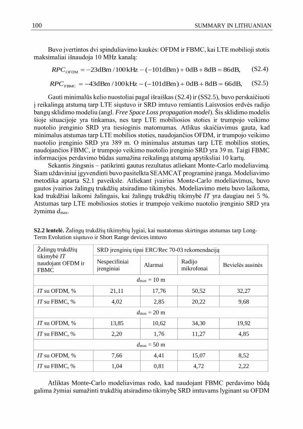
100 SUMMARY IN LITHUANIAN
Buvo įvertintos dvi spinduliavimo kaukės: OFDM ir FBMC, kai LTE mobilioji stotis
maksimaliai išnaudoja 10 MHz kanalą:
dB,86dB8dB0)dBm101(kHz100/dBm23OFDM RPC (S2.4)
dB,66dB8dB0)dBm101(kHz100/dBm43FBMC RPC (S2.5)
Gauti minimalūs kelio nuostoliai pagal išraiškas (S2.4) ir (SS2.5), buvo perskaičiuoti
į reikalingą atstumą tarp LTE siųstuvo ir SRD imtuvo remiantis Laisvosios erdvės radijo
bangų sklidimo modeliu (angl. Free Space Loss propagation model). Šis sklidimo modelis
šioje situacijoje yra tinkamas, nes tarp LTE mobiliosios stoties ir trumpojo veikimo
nuotolio įrenginio SRD yra tiesioginis matomumas. Atlikus skaičiavimus gauta, kad
minimalus atstumas tarp LTE mobilios stoties, naudojančios OFDM, ir trumpojo veikimo
nuotolio įrenginio SRD yra 389 m. O minimalus atstumas tarp LTE mobilios stoties, naudojančios FBMC, ir trumpojo veikimo nuotolio įrenginio SRD yra 39 m. Taigi FBMC
informacijos perdavimo būdas sumažina reikalingą atstumą apytiksliai 10 kartų.
Sekantis žingsnis – patikrinti gautus rezultatus atliekant Monte-Carlo modeliavimą.
Šiam uždaviniui įgyvendinti buvo pasitelkta SEAMCAT programinė įranga. Modeliavimo
metodika aptarta S2.1 paveiksle. Atliekant įvairius Monte-Carlo modeliavimus, buvo
gautos įvairios žalingų trukdžių atsiradimo tikimybės. Modeliavimo metu buvo laikoma,
kad trukdžiai laikomi žalingais, kai žalingų trukdžių tikimybė IT yra daugiau nei 5 %.
Atstumas tarp LTE mobiliosios stoties ir trumpojo veikimo nuotolio įrenginio SRD yra
žymima dmax.
S2.2 lentelė. Žalingų trukdžių tikimybių lygiai, kai nustatomas skirtingas atstumas tarp Long-Term Evolution siųstuvo ir Short Range devices imtuvo
Žalingų trukdžių tikimybė IT
naudojant OFDM ir FBMC
SRD įrenginių tipai ERC/Rec 70-03 rekomendaciją
Nespecifiniai įrenginiai
Alarmai Radijo mikrofonai
Bevielės ausinės
dmax = 10 m
IT su OFDM, % 21,11 17,76 50,52 32,27
IT su FBMC, % 4,02 2,85 20,22 9,68
dmax = 20 m
IT su OFDM, % 13,85 10,62 34,30 19,92
IT su FBMC, % 2,20 1,76 11,27 4,85
dmax = 50 m
IT su OFDM, % 7,66 4,41 15,07 8,52
IT su FBMC, % 1,04 0,81 4,72 2,22
Atliktas Monte-Carlo modeliavimas rodo, kad naudojant FBMC perdavimo būdą
galima žymiai sumažinti trukdžių atsiradimo tikimybę SRD imtuvams lyginant su OFDM

SUMMARY IN LITHUANIAN 101
(žiūrėti S2.2 lentelę). LTE mobilioji stotis nekelia žalingų trukdžių SRD imtuvams, kai
atstumas yra bent 50 m. Vertinant tris skirtingus atstumus tarp LTE siųstuvo ir SRD
imtuvo gauta, kad FBMC gali sumažinti trukdžių atsiradimo tikimybę SRD imtuvams
lyginant su OFDM daugiau 2,5 karto (dmax = 10 m atvejis), daugiau nei 3 kartus (dmax =
20 m atvejis) daugiau nei 3,2 karto (dmax = 50 m atvejis). Gautų rezultatų pasikliautinumo
intervalas yra 95 %.
Nagrinėjant pačią kritiškiausią elektromagnetinio suderinamumo situaciją, kai
atstumas tarp LTE siųstuvo ir SRD imtuvo lygus 10 m, matyti, kad nespecifiniai SRD
įrenginiai ir aliarmo davikliai gali būti nepaveikti žalingų trukdžių (trukdžiai laikomi žalingais, kai žalingų trukdžių tikimybė IT yra daugiau nei 5 %.), jeigu šiuolaikiniuose
LTE tinkluose būtų naudojama FBMC informacijos perdavimo būdas. Padidinus atstumą
tarp LTE siųstuvo ir SRD imtuvo iki 20 m dar daugiau SRD įrenginių gali būti
elektromagnetiškai suderinami su LTE mobiliosiomis stotimis, kai jos veikia kaimyninėje
dažnių juostoje. Kai atstumas tarp LTE siųstuvo ir SRD imtuvo lygus 50 m, visų nagrinėtų
SRD įrenginių neveikia žalingi trukdžiai, jei būtų naudojamas FBMC informacijos
perdavimo būdas.
Visų modeliavimų metu nespecifiniams SRD imtuvams, aliarmo davikliamas,
bevielėms ausinėms buvo taikomas C/(I+N) = 8 dB žalingų trukdžių kriterijus. Gautų
rezultatų pasikliautinumo intervalas yra 95 %. Radijo mikrofonams buvo taikomas 17 dB
žalingų trukdžių kriterijus nustatytas pagal EN 300 220 (ETSI 2012), EN 301 357 (ETSI 2008) SRD standartus.
3. Eksperimentinis žalingų trukdžių atsiradimo tyrimas
Šiame skyriuje pateikti eksperimentinių tyrimų rezultatai, kuriais siekta patikrinti teorinių
skaičiavimų ir modeliavimų metu gautus rezultatus.
Matavimams naudoti dviejų skirtingų gamintojų nespecifiniai SRD įrenginiai:
Semtech SX1231 ir Analog Devices ADF7023. Visi matavimai atlikti Vilniaus Gedimino
technikos universiteto Elektronikos fakulteto Telekomunikacijų inžinerijos katedrojoje 2013 metais.
Pagrindiniai matavimų etapai:
Sukonfigūruojamas informacijos perdavimo kanalas tarp SRD įrenginių.
Sukonfigūruojama LTE mobilioji stotis ir nustatomas maksimalaus siuntimo rėžimas.
SRD siųstuvas siunčia duomenis serijomis po 1000 paketų. LTE mobilioji stotis artinama prie SRD imtuvo. SRD imtuve skaičiuojamas gautų
paketų procentas.
Matavimų metu LTE mobiliosios stoties šalutinės spinduliuotės galia neviršijo 3GPP
136 101 rekomendacijoje nustatytų maksimalių ribų:–23 dBm/100 kHz lygio šalutinės
spinduliuotės galia.
SRD imtuvo dažnis matavimų metu buvo nustatytas ties 868,1 MHz, kaip nusako
ERC/Rec 70-03 rekomendacija.

102 SUMMARY IN LITHUANIAN
Vokietijos Federalinė tinklų agentūra ECC SE24 darbo grupėje pristatė studiją
(Federal Network Agency 2013), kurioje daroma išvada, kad šiuolaikinių LTE mobiliųjų
stočių šalutinės spinduliuotės lygiai yra žymiai mažesni nei leidžia 3GPP standartas.
Vokietijos Federalinė tinklų agentūros studija (Federal Network Agency 2013) parodo,
kad realaus LTE įrenginio šalutinė spinduliuotė yra apytiksliai –46 dBm/100 kHz, nors
3GPP standartas leidžia –23 dBm/100 kHz. Vokiečių atliktoje studijoje šis įrenginys
pristatytas kaip tipinis.
Gauti eksperimentinių matavimų rezultatai buvo papildomai patikrinti naudojant
laisvosios erdvės sklidimo modelį (S2.6).
),m,log(20)GHz,log(205,32 dfPL (S2.6)
čia PL – kelios nuostoliai, dB; f – signalo dažnis, GHz; d – nuotolis, m.
Faktorius prieš nuotolio algoritmą yra vadinamas kelio nuostolių eksponentė γ.
Radijo sistemų literatūroje (Goldsmith 2005) kelio nuostolių eksponentė γ tradiciškai
kinta nuo 2, kas yra laikoma sklidimu laisvojoje erdvėje, iki 4, kas yra laikoma sklidimu
erdvėje su dideliais aplinkos nuostoliais. Bet radijo bangų sklidimas viduje pastatų sukuria
didesnį slopinimą (dėl didelio kiekio atspindžių, signalo išsklaidymo nuo aplinkoje
esančių objektų), nei radijo bangų sklidimas išorėje su kliūtimis (Goldsmith 2005). Taigi
kelio nuostolių eksponentė γ vidinėse patalpose gali siekti iki 6,5 (Goldsmith 2005). Šioje
disertacijoje visi matavimai buvo atlikti viduje pastato, tipinėje biuro aplinkoje, todėl buvo
pasirinkta, kad kelio nuostolių eksponentė γ = 5. S2.2 lentelėje matyti eksperimentinių matavimų rezultatų sulyginimas su teoriniais
skaičiavimais, siekiant patikrinti gautų rezultatų patikimumą. LTE mobiliosios stoties
šalutinės spinduliuotės lygis atitinka 3GPP 136 101 standartą.
S2.2 lentelė. Matuoto ir apskaičiuoto C/I trukdžių kriterijaus palyginimas, kai trukdis veikė pagal 3GPP 136 101 standartą
Eksperimentiniai matavimai atlikti Semtech gamintojo SRD įrenginiu
1, 2, 3Atstumas, m C, dBm I, dBm C/I pamatuotas, dB
1C/I skaičiuotas pagal PL išraišką,
dB
9 –92 –104 12 10
4 –72 –85 13 12
Eksperimentiniai matavimai atlikti Analog Devices gamintojo SRD įrenginiu
8 –94 –101 7 5
3 –72 –82 10 6
Pastaba1: Normalus imtuvo darbo rėžimas laikomas, kai prarastų paketų procentas yra mažiau nei 10.
Pastaba2: Atstumas, kai SRD imtuvo darbas sutrikdomas.
Pastaba3: C/I kriterijus apskaičiuojamas taip: C/I apskaičiuotas = –23 dBm/100 kHz – kelio nuostoliai – C, dBm.
S2.2 lentelėje matyti, kad C/I pamatuotos reikšmės koreliuoja su teoriškai
apskaičiuotomis C/I reikšmėmis. Pamatuotos C/I reikšmės kinta intervale nuo 7 dB iki
13 dB. Apskaičiuotos C/I reikšmės kinta nuo 6 dB iki 12 dB.
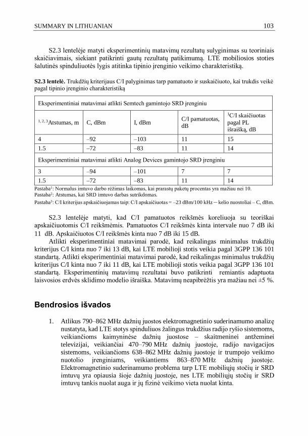
SUMMARY IN LITHUANIAN 103
S2.3 lentelėje matyti eksperimentinių matavimų rezultatų sulyginimas su teoriniais
skaičiavimais, siekiant patikrinti gautų rezultatų patikimumą. LTE mobiliosios stoties
šalutinės spinduliuotės lygis atitinka tipinio įrenginio veikimo charakteristiką.
S2.3 lentelė. Trukdžių kriterijaus C/I palyginimas tarp pamatuoto ir suskaičiuoto, kai trukdis veikė pagal tipinio įrenginio charakteristiką
Eksperimentiniai matavimai atlikti Semtech gamintojo SRD įrenginiu
1, 2, 3Atstumas, m C, dBm I, dBm C/I pamatuotas, dB
1C/I skaičiuotas
pagal PL išraišką, dB
4 –92 –103 11 15
1.5 –72 –83 11 14
Eksperimentiniai matavimai atlikti Analog Devices gamintojo SRD įrenginiu
3 –94 –101 7 7
1.5 –72 –83 11 14
Pastaba1: Normalus imtuvo darbo rėžimas laikomas, kai prarastų paketų procentas yra mažiau nei 10.
Pastaba2: Atstumas, kai SRD imtuvo darbas sutrikdomas.
Pastaba3: C/I kriterijus apskaičiuojamas taip: C/I apskaičiuotas = –23 dBm/100 kHz – kelio nuostoliai – C, dBm.
S2.3 lentelėje matyti, kad C/I pamatuotos reikšmės koreliuoja su teoriškai
apskaičiuotomis C/I reikšmėmis. Pamatuotos C/I reikšmės kinta intervale nuo 7 dB iki
11 dB. Apskaičiuotos C/I reikšmės kinta nuo 7 dB iki 15 dB.
Atlikti eksperimentiniai matavimai parodė, kad reikalingas minimalus trukdžių
kriterijus C/I kinta nuo 7 iki 13 dB, kai LTE mobilioji stotis veikia pagal 3GPP 136 101
standartą. Atlikti eksperimentiniai matavimai parodė, kad reikalingas minimalus trukdžių
kriterijus C/I kinta nuo 7 iki 11 dB, kai LTE mobilioji stotis veikia pagal 3GPP 136 101
standartą. Eksperimentinių matavimų rezultatai buvo patikrinti remiantis adaptuota
laisvosios erdvės sklidimo modelio išraiška. Matavimų neapibrėžtis yra mažiau nei ±5 %.
Bendrosios išvados
1. Atlikus 790–862 MHz dažnių juostos elektromagnetinio suderinamumo analizę
nustatyta, kad LTE stotys spinduliuos žalingus trukdžius radijo ryšio sistemoms,
veikiančioms kaimyninėse dažnių juostose – skaitmeninei antžeminei
televizijai, veikiančiai 470–790 MHz dažnių juostoje, radijo navigacijos
sistemoms, veikiančioms 638–862 MHz dažnių juostoje ir trumpojo veikimo
nuotolio įrenginiams, veikiantiems 863–870 MHz dažnių juostoje.
Elektromagnetinio suderinamumo problema tarp LTE mobiliųjų stočių ir SRD
imtuvų yra opiausia šioje dažnių juostoje, nes LTE mobiliųjų stočių ir SRD imtuvų tankis nuolat auga ir jų fizinė veikimo vieta nuolat kinta.

104 SUMMARY IN LITHUANIAN
2. FBMC informacijos perdavimo būdas yra spektriškai efektyvesnis nei OFDM.
LTE sistemos, naudojančios FMBC informacijos perdavimo būdą, turėtų 20 dB
žemesnį šalutinės spinduliuotės lygį, lyginant su OFDM.
3. Atlikus Monte-Carlo modeliavimą nustatyta, kad naudojant FBMC informacijos
perdavimo būdą, galima žymiai sumažinti trukdžių atsiradimo tikimybę SRD
imtuvams, lyginant su OFDM. LTE mobilioji stotis nekelia žalingų trukdžių
SRD imtuvams, kai atstumas tarp jų yra bent 50 m. FBMC gali sumažinti
trukdžių atsiradimo tikimybę SRD imtuvams daugiau nei 2,5 karto. Gautų
rezultatų pasikliautinumo intervalas yra 95 %.
4. Eksperimentiniais matavimais nustatyta, kad minimalus apsauginis kriterijus
C/I turi būti daugiau nei 7 dB, kai LTE mobiliosios stoties šalutinė spinduliuotė neviršija 3GPP TS 36.101 standarto reikalavimų. Eksperimentiniais matavimais
nustatyta, kad minimalus apsauginis kriterijus C/I turi būti daugiau nei 7 dB, kai
LTE mobiliosios stoties šalutinė spinduliuotė atspindi realaus įrenginio veikimo
charakteristikas. Matavimų neapibrėžtis yra mažiau nei ±5 %. 5. Eksperimentiniais matavimais nustatyta, kad laisvojo sklidimo modelio kelio
nuostolių eksponentė γ turi būti lygi 5, siekiant atspindėti situaciją, kai
eksperimentiniai matavimai atliekami tipinėje biuro aplinkoje.

105
Annexes1
Annex A. The co-authors agreement to present publications material in the
dissertation.
Annex B. Copies of scientific publications by the author on the topic of the
dissertation.
1The annexes are supplied in the enclosed compact disc
Evaldas STANKEVIČIUS
INVESTIGATION OF TECHNIQUES FOR REDUCING MOBILE COMMUNICATION SYSTEMS HARMFUL OUT-OF-BAND EMISSION
Doctoral Dissertation
Technological Sciences, Electrical and Electronic Engineering (01T)
Evaldas STANKEVIČIUS
MOBILIOJO RYŠIO SISTEMŲ ŽALINGOS ŠALUTINĖS SPINDULIUOTĖS MAŽINIMO BŪDŲ TYRIMAS
Daktaro disertacija
Technologijos mokslai, Elektros ir elektronikos inžinerija (01T)
2017 02 09. 10 sp. l. Tiražas 20 egz. Vilniaus Gedimino technikos universiteto leidykla „Technika“, Saulėtekio al. 11, 10223 Vilnius, http://leidykla.vgtu.lt
Spausdino BĮ UAB „Baltijos kopija“, Kareivių g. 13B, 09109 Vilnius