investigation of structural dynamics in a 2-meter …
TRANSCRIPT
1 American Institute of Aeronautics and Astronautics
INVESTIGATION OF STRUCTURAL DYNAMICS IN A 2-METER SQUARE SOLAR SAIL MODEL INCLUDING AXIAL LOAD EFFECTS
D.B. Holland* and L.N. Virgin**
Department of Mechanical Engineering and Materials Science Duke University
Durham, NC 27708
W. K. Belvin*** Structural Dynamics Branch
NASA Langley Research Center Hampton, VA 23681
Abstract
This paper presents a parameter study of the effect of boom axial loading on the global dynamics of a 2-meter solar sail scale model. The experimental model used is meant for building expertise in finite element analysis and experimental execution, not as a predecessor to any planned flight mission or particular design concept. The results here are to demonstrate the ability to predict and measure structural dynamics and mode shapes in the presence of axial loading.
Introduction and Background The conceptual phase of solar sail propulsion has existed for the better part of a century. The first known concepts of solar propulsion were explored by Tsander and Tsiolkovsky in the 1920’s. In the 1950’s Wiley and later Garwin published articles envisioning solar sail vehicle systems. NASA began exploring heliogyro solar sail concepts for a Halley’s comet rendezvous mission in the 1970’s, but the idea was dropped due to the high risks involved (Ref. 1). Low-level interest and research into the subject continued and has resulted in multiple proposed missions and designs (Ref. 2-4). To date no flight test has taken place. Before the realization of a solar sail flight, sufficient technology development and *Graduate Research Assistant; Member AIAA ** Professor, Department of Mechanical Engineering and Materials Science; Member AIAA *** Lead, Resilient Materials and Structures; Senior Member AIAA
performance experimentation must take place. In the technology development arena, advances in material sciences (Ref. 5-6) and controls (Ref. 7-8) are pushing the boundaries of solar sail size, efficiency and flight precision. In addition to this, ground test experiments and structural data acquisition has begun in a number of areas, including deployment, subsystem integration, structural thermal loading, and structural dynamics of both solar sails and other gossamer spacecraft structures (Ref. 9-14). Developing ground testing methods and ground testbed experiments for solar sails has become a focus of the NASA Langley Research Center. The goal is to develop a knowledge base and high level of expertise in structural static and dynamic experiments on solar sail scale models. This information will then be used to provide validation for the analytical models required for actual flight testing. A crucial step in the development of solar sail capability has been the ability to accurately predict structural system behavior, especially through finite element analysis. Key challenges such as numerical stability, localized buckling (wrinkling) and geometrically nonlinear characteristics have resulted in a number of methods for handling the analysis of membrane structural behavior (Ref. 15-19). Proper modeling of membrane behavior represents a difficult task in the process of analyzing the global structural behavior of a gossamer space structure. In a recent analytical study, the design parameters of a square solar sail, similar to Figure 1, was undertaken (Ref. 20). In this study, which was primarily an optimization of size and weight parameters to achieve maximum acceleration, an interesting conjecture concerning the sail booms was made. In an effort to minimize the mass and size of the booms, it was proposed to use booms

2 American Institute of Aeronautics and Astronautics
in a buckled configuration, both to provide tension in the sail membrane and to take advantage of the post buckled stiffness that exists as stored bending energy in the boom. This allowed for much lighter structures to be analyzed and resulted in higher theoretical vehicle efficiency.
Figure 1: Square Sail Design with Four-Quadrant Membranes (Picture Courtesy of NASA) The incorporation of the buckled boom concept in a square solar sail induces a new structural dynamics problem that requires analysis. The dynamic analysis of post-buckled columns has previously been explored (Ref. 21), but not in the context of solar sails or when coupled to a tensioned membrane. Development of analytical modeling methods to correlate ground test experimental results is necessary for advancement towards flight testing.
Experimental Model Description A four-quadrant square solar sail model was constructed and used for the experimental portion of the parameter study. It consisted of four triangular shaped membranes of Kapton polyimide film, four tubular steel booms, a central hub used for mounting, and various small hardware used for attaching the sail to the booms. The model is shown schematically in Figure 2.
Figure 2: Layout Sketch of 2-meter Experimental Model The sail material was 1-mil thick, aluminized on one side, and contained a pattern of small holes to allow slight air flow through the membrane and to decrease the global sail density. The booms were constructed from type 304 stainless steel with an outer diameter of 0.188 inches and an inner diameter of 0.118 inches. The boom length was 54 inches, which accommodated a triangular sail membrane with a base length of 2 meters and a height of 1 meter. The hub was constructed from aluminum, and allowed for direct attachment to a static fixture rig. The corners of the sail were connected directly to the hub and to the boom through the use of adjustable turnbuckles. The turnbuckles allowed the corner of the film to rotate perpendicular to the membrane plane and perpendicular to the boom axis. The turnbuckles were adjustable in order to change the membrane tension and thus the axial loading on the booms. The assembled experimental model is shown in Figure 3.

3 American Institute of Aeronautics and Astronautics
Figure 3: Assembled Experimental Test Article
Experimental Hardware Configuration
The experiments took place in the laboratory of the Structural Dynamics Facility at NASA Langley Research Center. The sail was mounted on a steel truss 12 feet above the floor of the laboratory. The model was installed with the plane of the sail parallel to the plane of the floor, as shown in Figure 4.
Figure 4: Test Article Configuration and Instrumentation This was done to better simulate the membrane tension caused by solar loading and to ensure equal axial loading could be achieved in the booms. In order to reduce the deflection of the booms caused by the mass of the sail, a mass off-
loading system was constructed and mounted above the sail. Known springs were attached to fishing lines, which were attached to the end corners of the boom. The structure was excited using a 3-lbf Ling dynamic shaker. The shaker used a magnetic attachment at the end of a stinger. This magnet was placed in proximity with the corner of one of the booms, providing a non-contact method of excitation as shown in Figure 5.
Figure 5: Magnetic Excitation System In addition, small retro-reflective targets were placed on the experimental model to facilitate the use of laser vibrometry for dynamic data collection. Both static and dynamic instrumentation were utilized in the experiments. Each boom had two strain gages installed 180° opposite from each other at a distance of one inch from the boom connection with the hub. These gages were used measure the axial loading and bending moment in the booms at the base for each dynamic trial. A PCB352A211 single axis accelerometer was attached to the sail boom corner nearest to the shaker. This signal was used as the input for frequency response measurements. Finally, a Polytec PSV-300 laser vibrometry system was used to induce dynamic excitation of the sail, measure dynamic response data and analyze the global response of the structure.
Experimental Procedure
A three step process was used to setup and collect dynamic response data. First, film tension was induced in the sail film by shortening the turnbuckle lengths approximately the same amount. Then an axial load reading was taken from the strain gages to determine the axial load
4 American Institute of Aeronautics and Astronautics
created by the sail tension. Finally, the scanning laser vibrometer was used to collect dynamic data from 121 data points on both the sail film and booms. A quasi-random excitation in the range of 0-50 Hz was used to excite the structure the laser vibrometer collected and analyzed FFT data in the same frequency range. This process was repeated for multiple axial loading levels.
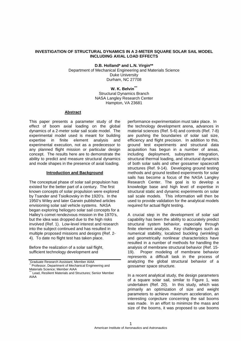
Experimental Results Utilizing the H2 frequency response results from the laser vibrometer, the characteristic structural response and mode shapes were determined for the various axial load cases. It was discovered that the global structural response was dominated by the boom response, and further that the response of a single boom was sufficient for determining natural frequencies of the structure under loading. A sample of this phenomenon is shown in Figure 6.
0 5 10 15 20 25 30 35 40 45 5010
-7
10-6
10-5
10-4
10-3
10-2
10-1
Sample Overall Frequency Response
Frequency (Hz)
Mag
nitu
de R
espo
nse
(m/s
/(m
/s2))
Complete Structural ResponseBoom ResponseSingle Boom Response
Figure 6: Sample Frequency Response Plot
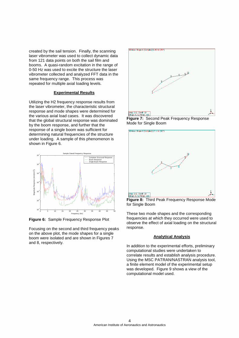
Focusing on the second and third frequency peaks on the above plot, the mode shapes for a single boom were isolated and are shown in Figures 7 and 8, respectively.
Figure 7: Second Peak Frequency Response Mode for Single Boom
Figure 8: Third Peak Frequency Response Mode for Single Boom These two mode shapes and the corresponding frequencies at which they occurred were used to observe the effect of axial loading on the structural response.
Analytical Analysis
In addition to the experimental efforts, preliminary computational studies were undertaken to correlate results and establish analysis procedure. Using the MSC PATRAN/NASTRAN analysis tool, a finite element model of the experimental setup was developed. Figure 9 shows a view of the computational model used.

5 American Institute of Aeronautics and Astronautics
Figure 9: Finite element model
Each boom in the model utilized twenty beam elements, which were assigned the appropriate material and dimensional properties corresponding to the experimental system. The sail membrane and corner attachments consisted of shell elements which were given the appropriate thickness and material properties. The turnbuckles were modeled as beam elements, and multi-point constraints (MPC’s) were used to simulate the appropriate degrees of freedom where the turnbuckles attached to both the sail and the booms. In order to simulate the mass offloading system, spring elements were attached to the four corners of the sail and fixed to ground. The finite element model was constrained at the center hub in all degrees of freedom, similar to the experimental setup. Gravitational loading was applied to the model, and tension was applied to the film by thermally shrinking the turnbuckle elements. The first step in the post-buckled dynamic analysis was to generate a prestressed static solution. This was done through a nonlinear static analysis using an arc-length stiffness update scheme in NASTRAN. Due to the extremely low bending stiffness in the shell elements, two steps were taken prior to applying the tension and gravitational loading. A random displacement field equal to the thickness of the material was applied to the sail to “push” the membrane out of plane in both positive and negative directions and increase the bending stiffness of the film. This in turn helped to stabilize the static stiffness matrix for further iterations. Next, a quasi-random positive and negative point-force field was applied to the membrane to further increase the static bending stiffness of the film. In addition, this step worked
to provide geometric imperfection to the model, avoiding stiffness singularities and increasing model stability. Finally, gravity and tension loading were added in multiple stages. Each stage was an order of magnitude higher than the previous stage, until 100% of the loading was achieved. This was done to maintain a numerically stable stiffness as the membrane ramped up through both out of plane displacement and localized wrinkling pattern formulation. A direct frequency response solution was generated from the static finite element results using a restart procedure from the desired axial load level. For the frequency response, a small out of plane loading was applied to the corner of an axial boom, similar to the experimental setup. The natural frequencies of the structure were determined from the results of the frequency response
Analytical Results
Figure 10 shows a typical finite element static result prior to performing a dynamic frequency response analysis on the finite element model.
Figure 10: Typical static finite element result
In a similar result to the experimental analysis, it was discovered that the boom frequency response dominated the global structural response. A sample frequency response plot for 4 nodes on a single boom is shown in Figure 11.

6 American Institute of Aeronautics and Astronautics
0 5 10 15 20 25 30 35 40 45 5010
-7
10-6
10-5
10-4
10-3
10-2
Sample FEA Frequency Response
Frequency (Hz)
Mag
nitu
de R
espo
nse
(m/s
/(m
/s2))
Boom Node 5Boom Node 11Boom Node 16Boom Node 21
Figure 11: Typical Boom Finite Element Frequency Response
Effects of Axial Load
Using the response of both the experimental data and the finite element results, the shifting of the structural natural frequency as a function of the axial loading is shown in Figure 12. In the figure, the axial loading is normalized with respect to the Euler buckling load of a clamped-pinned beam. The first and second natural frequencies are converted to their respective radial frequencies squared and normalized with respect to the unloaded radial frequencies of a clamped-pinned beam.
0 0.1 0.2 0.3 0.4 0.5 0.6 0.7 0.8 0.9 10
0.1
0.2
0.3
0.4
0.5
0.6
0.7
0.8
0.9
1Natural Frequency vs. Axial Load
Normalized Radial Frequency (w2 /w[0]2)
Nor
mal
ized
Axi
al L
oad
(P/P
[cr]
)
1st Mode FEM Data1st Mode Exp. Data2nd Mode FEM Data2nd Mode Exp. Data
Linear Beam Theory
Figure 12: Normalized Results of Natural
Frequency vs. Axial Load
The frequency shifting caused by the changing axial load in the structure is clearly visible for both first and second modal frequencies. This is expected due to the detrimental effect of axial loading on the bending stiffness of the boom. The
finite element results and the experimental results for both modes appear to decrease at slower rate than linear theory predicts. In addition, the experimental results appear to curve away from the linear theory. This was an expected result for a beam with initial imperfection. (Ref. 21) Although damping has not been considered in this paper, and indeed solar sail operational conditions make damping a less important factor, clearly any correlation between theoretical models and laboratory-based experiments on the dynamics of solar sails will need to include some damping effects. Damping in solar sail type models originates in a number of ways, including nonlinearity. For slender, axially-loaded structures with linear viscous damping, it has been shown that since damping ratios depend on stiffness, and since compressive axial loads tend to reduce (bending) stiffness, it follows that vibrations tend to cease prior to buckling (Ref. 22). That is, damping becomes critical before the stiffness becomes zero. However, for most practical situations (in which damping is light) this is a relatively minor effect. An attempt to extend both the finite element results and the experimental results was performed. However, the results from these trials were inconclusive relative to the analytical theory and further development of analytical models is required.
Conclusion Combining finite element analysis and experimental results, a comparison between natural frequencies of axially loaded solar sail structures was performed. The results show that finite element analysis tools can be utilized to predict the structural dynamics of a square solar sail structure in the pre-buckled regime. Further dynamic analysis is required to extend into post-buckled results.
References 1. Salama M., McInnes, C., and Mulligan, P., “Gossamer Sailcraft Technology.” Gossamer Spacecraft: Membrane and Inflatable Structures Technology for Space Applications. Ed. C. H. M. Jenkins. Reston, VA: AIAA Inc., 2001. 481-502. 2. Chmielewski, A., Moore, C., and Howard, R., The Gossamer Initiative. IEEE paper 0-7803-5846-5/00, Jan. 2000.

7 American Institute of Aeronautics and Astronautics
3. West, J., and Derbes, B., Solar Sail Vehicle System Design for the Geostorm Warning Mission. AIAA-2000-5326. 4. Leipold, M., Benda, M., Herbeck, L., Pagel, G., Seboldt, W., and Sickinger, C., ODISSEE – A Proposal for Demonstration of a Solar Sail in Earth Orbit. Pasadena, CA, April 27-May 1 1998. International Academy of Astronautics. Presented at the IAA Third International Conference on Low-Cost Planetary Missions. 5. St. Clair, A., St. Clair, T., and Slemp, W., ”Optically Transparent/Colorless Polyimides.” Recent Advances in Polyimide Science and Technology. Weber, W.; Gupta, M. Editors, Society of Plastics Engineers, Poughkeepsie, NY, 1987, 1175-1195. 6. Watson, J., Static-Test Results for the Characterization of Inflatable Rigidizable Columns. AIAA Paper 2001-1269, 2nd Gossamer Spacecraft Forum, Seattle, WA, April 2001. 7. Quadrelli, M. and Sirlin, S., Modeling and Control of Membranes for Gossamer Spacecraft. AIAA Paper 2001-1201, 2nd Gossamer Spacecraft Forum, Seattle, WA, April 2001. 8. Mettler, E. and Ploen, S., Solar Sail Dynamics and Control using a Boom Mounted Bus Articulated by a Bi-State Two-Axis Gimbal and Reaction Wheels. AIAA Paper 2002-4992, AIAA Astrodynamics Specialist Conference and Exhibit, Monterey, CA, August 2002. 9. NGST ½ -scale Inflatable Sunshield Deployment. Final Report by ILC Dover and L’Garde, June 1998 10. Lienard, S., Johnston, J., Ross, B., and Smith, J., Dynamic Testing of a Subscale Sunshield for the Next Generation Space Telescope (NGST). AIAA Paper 2001-1268, 2nd Gossamer Spacecraft Forum, Seattle, WA, April 2001. 11. Murphy, D., Murphey, T., and Gierow, P., Scalable Solar Sail Subsystem Design Considerations. AIAA Paper 2002-1703, 3rd Gossamer Spacecraft Forum, Denver, CO, April, 2002. 12. Wada, B., and Lou, M., Pre-Flight Validation of Gossamer Structures. AIAA Paper 2002-1373, 3rd Gossamer Spacecraft Forum, Denver, CO, April, 2002.
13. Pappa, R., Lassiter, J., and Ross, B., Structural Dynamics Experimental Activities in Ultra-Lightweight and Inflatable Space Structures. AIAA Paper 2001-1263, 2nd Gossamer Spacecraft Forum, Seattle, WA, April 2001. 14. Slade, K., Belvin, W, and Behun, V., Solar Sail Loads, Dynamics, and Membrane Studies. AIAA Paper 2002-1265, 3rd Gossamer Spacecraft Forum, Denver, CO, April 2002. 15. Adler, A., and Mikulas, M., Application of a Wrinkled Membrane Finite Element Approach to Advanced Membrane Structures. AIAA Paper 2001-4646, AIAA Space Conference and Exposition, Albuquerque, NM, August 2001. 16. Johnston, J., Finite Element Analysis of Wrinkled Membrane Structures for Sunshield Applications. AIAA Paper 2002-1456, 3rd Gossamer Spacecraft Forum, Denver, CO, April 2002. 17. Lee, K., and Lee, S., Analysis of Gossamer Space Structures Using Assumed Strain Formulation Solid Shell Elements. AIAA Paper 2002-1559, 3rd Gossamer Spacecraft Forum, Denver CO, April 2002. 18. Wong, Y., and Pellegrino, S., Computation of Wrinkle Amplitudes in Thin Membranes. AIAA Paper 2002-1369, 3rd Gossamer Spacecraft Forum, Denver, CO, April 2002. 19. Yang, B., Ding, H., Lou, M., and Fang, H., A New Approach to Wrinkling Prediction for Space Membrane Structures. AIAA Paper 2001-1348, 2nd Gossamer Spacecraft Forum, Seattle, WA, April 2001. 20. Greschik, G., and Mikulas, M., Design Study of a Square Solar Sail Architecture. AIAA Paper 2001-1259, 2nd Gossamer Spacecraft Forum, Seattle, WA, April 2001. 21. Virgin, L., “The Dynamics of Symmetric Post-Buckling”. International Journal of Mechanical Science, Vol. 27 n. 4 (1985), 235-248. 22. Virgin, L., “Parametric studies of the dynamic evolution through a fold”. Journal of Sound and Vibration, Vol. 110 (1986), 99-109.