investigation of carbon fiber composite cables (cfcc) in
TRANSCRIPT
Final Report
Investigation of Carbon Fiber Composite Cables (CFCC) in
Prestressed Concrete Piles
Contract Number BDK83-977-17
FSU Project ID: 031045
Submitted to:
Florida Department of Transportation
Research Center
605 Suwannee Street
Tallahassee, Florida 32399-0450
Sam Fallaha, P.E.
Project Manager
FDOT Structures Design Office
Prepared by:
Michelle Roddenberry, Ph.D., P.E.Principal Investigator
Primus Mtenga, Ph.D., P.E.Co-Principal Investigator
Kunal JoshiGraduate Research Assistant
FAMU-FSU College of Engineering
Department of Civil and Environmental Engineering
2525 Pottsdamer Street, Rm A129
Tallahassee, FL 32310-6046
April 2014

DISCLAIMER
The opinions, findings, and conclusions expressed in this publication are those of theauthors, who are responsible for the facts and accuracy of the data presented herein.The contents do not necessarily reflect the views or policies of the Florida Departmentof Transportation or the Research and Special Programs Administration. This reportdoes not constitute a standard, specification, or regulation.
The report is prepared in cooperation with the State of Florida Department of Trans-portation and the U.S. Department of Transportation.
ii

Approximate conversion to SI units
Symbol When you know Multiply by To find Symbol
Length
in. inches 25.4 millimeters mm
ft feet 0.305 meters m
yd yards 0.914 meters m
mi miles 1.61 kilometers km
Area
in2 square inches 645.2 square millimeters mm2
ft2 square feet 0.093 square meters m2
yd2 square yard 0.836 square meters m2
ac acres 0.405 hectares ha
mi2 square miles 2.59 square kilometers km2
Volume
fl oz fluid ounces 29.57 milliliters mL
gal gallons 3.785 liters L
ft3 cubic feet 0.028 cubic meters m3
yd3 cubic yards 0.765 cubic meters m3
Mass
oz ounces 28.35 grams g
lb pounds 0.454 kilograms kg
T short tons (2000 lb) 0.907 megagrams Mg
Temperature
°F Fahrenheit 59 (F− 32) Celsius ◦C
Illumination
fc foot-candles 10.76 lux lx
fl foot-Lamberts 3.426 candelam2
cdm2
Force/Stress/Pressure
lbf poundforce 4.45 newtons N
k kips 4.45 kilonewtons kNlbfin2 (or psi) poundforce
square inch 6.89 kilopascals kPakin2 (or ksi) kips
square inch 6.89 megapascals MPa
iii

Approximate conversion to imperial units
Symbol When you know Multiply by To find Symbol
Length
mm millimeters 0.039 inches in.
m meters 3.28 feet ft
m meters 1.09 yards yd
km kilometers 0.621 miles mi
Area
mm2 square millimeters 0.0016 square inches in2
m2 square meters 10.764 square feet ft2
m2 square meters 1.195 square yards yd2
ha hectares 2.47 acres ac
km2 square kilometers 0.386 square miles mi2
Volume
mL milliliters 0.034 fluid ounces fl oz
L liters 0.264 gallons gal
m3 cubic meters 35.314 cubic feet ft3
m3 cubic meters 1.307 cubic yards yd3
Mass
g grams 0.035 ounces oz
kg kilograms 2.202 pounds lb
Mg megagrams 1.103 short tons (2000 lb) T
Temperature
◦C Celsius 95C+ 32 Fahrenheit °F
Illumination
lx lux 0.0929 foot-candles fccdm2
candelam2 0.2919 foot-Lamberts fl
Force/Stress/Pressure
N newtons 0.225 poundforce lbf
kN kilonewtons 0.225 kips k
kPa kilopascals 0.145 poundforcesquare inch
lbfin2 (or psi)
MPa megapascals 0.145 kipssquare inch
kin2 (or ksi)
iv

Technical Report Documentation Page 1. Report No.
2. Government Accession No.
3. Recipient's Catalog No.
4. Title and Subtitle Investigation of Carbon Fiber Composite Cables (CFCC) in Prestressed Concrete Piles
5. Report Date April 2014
6. Performing Organization Code
7. Author(s) M. Roddenberry, P. Mtenga, and K. Joshi
8. Performing Organization Report No. FSU Project ID 031045
9. Performing Organization Name and Address FAMU-FSU College of Engineering Department of Civil and Environmental Engineering 2525 Pottsdamer St. Rm. A129 Tallahassee, FL 32310-6046
10. Work Unit No. (TRAIS)
11. Contract or Grant No. BDK83-977-17
12. Sponsoring Agency Name and Address Florida Department of Transportation Research Center 605 Suwannee Street, MS 30 Tallahassee, FL 32399-0450
13. Type of Report and Period Covered Final Report
November 2011 – April 2014 14. Sponsoring Agency Code
15. Supplementary Notes
16. Abstract The Florida Department of Transportation (FDOT) commonly uses prestressed concrete piles in bridge foundations. These piles are prestressed with steel strands that, when installed in aggressive or marine environments, are subject to corrosion and therefore rapid degradation. Many solutions may address this issue, but they are not long-term. Hence, it would be desirable to use advanced materials that do not corrode. The goal of this research was to assess the suitability of using carbon fiber composite cables (CFCC), which do not corrode, in lieu of conventional steel prestressing strands. Five (5) 24-in. square prestressed concrete piles, three (3) 40-ft long and two (2) 100-ft long, were cast using 0.6-in. diameter CFCC strands produced by Tokyo Rope Manufacturing Company. A special anchoring system was used because CFCC strands cannot be conventionally gripped using wedges and a jack. The techniques employed to prestress these strands were documented, as well as the unique aspects involved in constructing and precasting CFCC-prestressed piles. During strand detensioning, stresses were monitored in the concrete at the piles' ends to determine the transfer length of CFCC strands, as a means of evaluating their bond characteristics. Development length tests and flexural tests were performed on two (2) of the 40-ft piles at the FDOT Marcus H. Ansley Structures Research Center to further assess the performance of the CFCC strands. Lastly, the two (2) 100-ft piles were driven at a bridge construction site, adjacent to standard steel-prestressed concrete piles. During driving operations, the behavior of the piles was monitored using embedded data collectors and a Pile Driving Analyzer®. The precasting efforts and test results show that the performance of piles prestressed with CFCC strands is comparable to those prestressed with steel. Using CFCC strands in prestressed concrete piles for bridge foundations, particularly in harsh environments, could potentially result in bridges that require less maintenance and have longer lifespans. 17. Key Word prestressed concrete pile, CFCC, CFRP
18. Distribution Statement No restrictions.
19. Security Classif. (of this report) Unclassified.
20. Security Classif. (of this page) Unclassified.
21. No. of Pages 307
22. Price
Form DOT F 1700.7 (8-72) Reproduction of completed page authorized
v

ACKNOWLEDGEMENTS
The authors would like to thank the Florida Department of Transportation (FDOT)
for providing the funding for this project, as well as the FDOT Structures Research
Center team. In particular, Sam Fallaha deserves considerable credit for the success
of this research, due to his initiative and unfaltering guidance. Much appreciation also
goes to William Potter for his insight and valuable discussions throughout the project,
as well as to Chris Weigly for his ebullience and for lending his data acquisition
expertise on a long, July day. Thanks go also to Rodrigo Herrera for his prowess on
geotechnical and pile driving matters and for his data analyses and report.
Gate Precast Company’s team at the Jacksonville, Florida, plant deserves plenty
of recognition for their role in making the research sound. Tom Newton and Scott
Henning were exceptionally professional and accommodating, while the unique details
required for constructing the precast concrete piles were worked out. Wendell Crews
and Zulfin Masinovic showed much enthusiasm and patience, and they made the work
enjoyable.
Thanks go to Mohamad Hussein at GRL Engineers, Inc., and Don Robertson and
Harold Dohn at Applied Foundation Testing, Inc., for providing pile driving testing
services. Thanks also go to Jonathan Chipperfield and Raphael Kampmann for their
moral support, help with specimen construction, and instrumentation installation.
vi

EXECUTIVE SUMMARY
The Florida Department of Transportation (FDOT) commonly uses prestressed con-
crete piles in bridge foundations. These piles are prestressed with steel strands that,
when installed in aggressive or marine environments, are subject to corrosion and
therefore rapid degradation. Many solutions may address this issue, but they are
not long–term. Hence, it would be desirable to use advanced materials that do not
corrode. The goal of this research was to assess the suitability of using carbon fiber
composite cables (CFCC), which do not corrode, in lieu of conventional steel pre-
stressing strands.
Five (5) 24–in. square prestressed concrete piles, three (3) 40–ft long and two (2) 100–
ft long, were cast using 0.6–in. diameter CFCC strands produced by Tokyo Rope Man-
ufacturing Company. A special anchoring system was used because CFCC strands
cannot be conventionally gripped using wedges and a jack. The techniques employed
to prestress these strands were documented, as well as the unique aspects involved
in constructing and precasting CFCC–prestressed piles. During strand detensioning,
stresses were monitored in the concrete at the piles’ ends to determine the transfer
length of CFCC strands, as a means of evaluating their bond characteristics.
Development length tests and flexural tests were performed on two (2) of the 40–ft
piles at the FDOT Marcus H. Ansley Structures Research Center to further assess
the performance of the CFCC strands. Lastly, the two (2) 100–ft piles were driven
at a bridge construction site, adjacent to standard steel–prestressed concrete piles.
During driving operations, the behavior of the piles was monitored using embedded
data collectors and a Pile Driving Analyzer®.
The precasting efforts and test results show that the performance of piles prestressed
with CFCC strands is comparable to those prestressed with steel. Using CFCC
strands in prestressed concrete piles for bridge foundations, particularly in harsh
environments, could potentially result in bridges that require less maintenance and
have longer lifespans.
vii
TABLE OF CONTENTS
Disclaimer . . . . . . . . . . . . . . . . . . . . . . . . . . . . . . . . . . . ii
SI Conversion Factor . . . . . . . . . . . . . . . . . . . . . . . . . . . . . iii
Technical Report Documentation Page . . . . . . . . . . . . . . . . . . v
Acknowledgements . . . . . . . . . . . . . . . . . . . . . . . . . . . . . . vi
Executive Summary . . . . . . . . . . . . . . . . . . . . . . . . . . . . . . vii
List of Figures . . . . . . . . . . . . . . . . . . . . . . . . . . . . . . . . . xii
List of Tables . . . . . . . . . . . . . . . . . . . . . . . . . . . . . . . . . . xvii
1 INTRODUCTION . . . . . . . . . . . . . . . . . . . . . . . . . . . . . 1
1.1 General . . . . . . . . . . . . . . . . . . . . . . . . . . . . . . . . . . 1
1.2 Problem Statement . . . . . . . . . . . . . . . . . . . . . . . . . . . . 1
1.3 Research Objectives . . . . . . . . . . . . . . . . . . . . . . . . . . . . 3
1.4 Report Organization . . . . . . . . . . . . . . . . . . . . . . . . . . . 3
2 LITERATURE REVIEW . . . . . . . . . . . . . . . . . . . . . . . . . 4
2.1 Introduction . . . . . . . . . . . . . . . . . . . . . . . . . . . . . . . . 4
2.2 Fiber Reinforced Plastic (FRP) . . . . . . . . . . . . . . . . . . . . . 4
2.3 Carbon Fiber Composite Cables (CFCC) . . . . . . . . . . . . . . . . 6
2.4 Transfer Length and Development Length Background . . . . . . . . 9
2.5 Research Performed on Transfer and Development Lengths of CFRPStrands . . . . . . . . . . . . . . . . . . . . . . . . . . . . . . . . . . 11
2.6 Other CFCC Coupling Method . . . . . . . . . . . . . . . . . . . . . 18
2.7 Flexure Test . . . . . . . . . . . . . . . . . . . . . . . . . . . . . . . . 21
viii

3 MATERIALS AND INSTRUMENTATION . . . . . . . . . . . . . . 24
3.1 Introduction . . . . . . . . . . . . . . . . . . . . . . . . . . . . . . . . 24
3.2 Prestressing Strands . . . . . . . . . . . . . . . . . . . . . . . . . . . 24
3.3 Coupling Device Anchorage System . . . . . . . . . . . . . . . . . . . 25
3.4 Concrete . . . . . . . . . . . . . . . . . . . . . . . . . . . . . . . . . . 27
3.5 Instrumentation . . . . . . . . . . . . . . . . . . . . . . . . . . . . . . 28
3.5.1 Strain Gages . . . . . . . . . . . . . . . . . . . . . . . . . . . 28
3.5.2 Deflection Gages . . . . . . . . . . . . . . . . . . . . . . . . . 29
3.5.3 Embedded Data Collectors (EDC) . . . . . . . . . . . . . . . . 29
3.5.4 Pile Driving Analyzer® (PDA) . . . . . . . . . . . . . . . . . 30
4 TEST SPECIMEN PRODUCTION . . . . . . . . . . . . . . . . . . 31
4.1 Introduction . . . . . . . . . . . . . . . . . . . . . . . . . . . . . . . . 31
4.2 Coupling at the FDOT Lab . . . . . . . . . . . . . . . . . . . . . . . 32
4.3 Pile Specimen Configuration . . . . . . . . . . . . . . . . . . . . . . . 32
4.4 Prestressing Losses . . . . . . . . . . . . . . . . . . . . . . . . . . . . 33
4.5 Pile Casting Bed Setup . . . . . . . . . . . . . . . . . . . . . . . . . . 35
4.5.1 Stressing Forces . . . . . . . . . . . . . . . . . . . . . . . . . . 35
4.5.2 Wooden Headers . . . . . . . . . . . . . . . . . . . . . . . . . 36
4.5.3 Prestressing Bed Layout . . . . . . . . . . . . . . . . . . . . . 37
4.6 Strand Installation . . . . . . . . . . . . . . . . . . . . . . . . . . . . 37
4.7 Coupler Staggering . . . . . . . . . . . . . . . . . . . . . . . . . . . . 38
4.8 Coupler Installation Procedures . . . . . . . . . . . . . . . . . . . . . 40
4.8.1 Setting the Anchoring Device . . . . . . . . . . . . . . . . . . 40
4.8.2 Setting Wedges and Sleeve Toward CFCC . . . . . . . . . . . 42
4.8.3 Finishing the Coupler Installation . . . . . . . . . . . . . . . . 43
4.9 Stressing the Strands . . . . . . . . . . . . . . . . . . . . . . . . . . . 45
4.10 Installation of Spirals and EDC . . . . . . . . . . . . . . . . . . . . . 48
4.11 Concrete Placement . . . . . . . . . . . . . . . . . . . . . . . . . . . . 49
4.12 Stress Release . . . . . . . . . . . . . . . . . . . . . . . . . . . . . . . 50
5 EXPERIMENTAL PROGRAM . . . . . . . . . . . . . . . . . . . . . 53
5.1 Transfer Length Tests . . . . . . . . . . . . . . . . . . . . . . . . . . 53
5.1.1 Introduction . . . . . . . . . . . . . . . . . . . . . . . . . . . . 53
5.1.2 Test Setup and Instrumentation . . . . . . . . . . . . . . . . . 53
5.2 Development Length and Flexure Tests . . . . . . . . . . . . . . . . . 56
ix
5.2.1 Introduction . . . . . . . . . . . . . . . . . . . . . . . . . . . . 56
5.2.2 Test Matrix and Setup . . . . . . . . . . . . . . . . . . . . . . 56
5.2.3 Instrumentation for the Development Length Tests . . . . . . 58
5.2.4 Instrumentation for Flexure Test . . . . . . . . . . . . . . . . 60
5.2.5 Test Procedure for Development Length and Flexure Tests . . 62
5.3 Pile Driving Test Setup . . . . . . . . . . . . . . . . . . . . . . . . . . 63
6 EXPERIMENTAL TEST RESULTS . . . . . . . . . . . . . . . . . . 64
6.1 Introduction . . . . . . . . . . . . . . . . . . . . . . . . . . . . . . . . 64
6.2 Transfer Length Measurements . . . . . . . . . . . . . . . . . . . . . 64
6.2.1 General . . . . . . . . . . . . . . . . . . . . . . . . . . . . . . 64
6.2.2 Measured Strains at Transfer . . . . . . . . . . . . . . . . . . 65
6.3 Development Length Test Results . . . . . . . . . . . . . . . . . . . . 71
6.3.1 Test 1 . . . . . . . . . . . . . . . . . . . . . . . . . . . . . . . 71
6.3.2 Test 2 . . . . . . . . . . . . . . . . . . . . . . . . . . . . . . . 74
6.4 Flexural Strength Test Results . . . . . . . . . . . . . . . . . . . . . . 76
6.5 Pile Driving Test Results . . . . . . . . . . . . . . . . . . . . . . . . . 79
6.5.1 Introduction . . . . . . . . . . . . . . . . . . . . . . . . . . . . 79
6.5.2 Embedded Data Collectors (EDC) Results . . . . . . . . . . . 79
6.5.3 Pile Driving Analyzer® (PDA) Results . . . . . . . . . . . . . 79
6.5.4 FDOT Summary Report . . . . . . . . . . . . . . . . . . . . . 80
7 DISCUSSION . . . . . . . . . . . . . . . . . . . . . . . . . . . . . . . 81
7.1 Introduction . . . . . . . . . . . . . . . . . . . . . . . . . . . . . . . . 81
7.2 Transfer Length of CFCC . . . . . . . . . . . . . . . . . . . . . . . . 81
7.3 Development Length Tests . . . . . . . . . . . . . . . . . . . . . . . . 82
7.4 Flexural Strength Tests . . . . . . . . . . . . . . . . . . . . . . . . . . 83
7.5 Pile Driving Tests . . . . . . . . . . . . . . . . . . . . . . . . . . . . . 84
7.6 Lessons Learned from First Attempt to Prestress . . . . . . . . . . . 84
8 SUMMARY AND CONCLUSIONS . . . . . . . . . . . . . . . . . . 88
8.1 Summary . . . . . . . . . . . . . . . . . . . . . . . . . . . . . . . . . 88
8.2 Conclusions . . . . . . . . . . . . . . . . . . . . . . . . . . . . . . . . 89
8.2.1 Transfer Length of CFCC . . . . . . . . . . . . . . . . . . . . 89
8.2.2 Development Length of CFCC . . . . . . . . . . . . . . . . . . 89
8.2.3 Flexural Strength of CFCC–Prestressed Pile . . . . . . . . . . 89
x

8.2.4 Pile Driving . . . . . . . . . . . . . . . . . . . . . . . . . . . . 90
8.2.5 Specimen Production . . . . . . . . . . . . . . . . . . . . . . . 90
8.3 Suggestions for Future Research . . . . . . . . . . . . . . . . . . . . . 90
Bibliography . . . . . . . . . . . . . . . . . . . . . . . . . . . . . . . . . . 92
Appendices . . . . . . . . . . . . . . . . . . . . . . . . . . . . . . . . . . . 95
Appendix A CFCC Product Information . . . . . . . . . . . . . . . . . 96
Appendix B Concrete Mix Design . . . . . . . . . . . . . . . . . . . . . 130
Appendix C Strand Template Layout and Pile Details . . . . . . . . . 137
Appendix D Prestress Loss Calculations . . . . . . . . . . . . . . . . . 144
Appendix E Pile Driving Tests and Reports . . . . . . . . . . . . . . . 148
Appendix F Moment Capacity Calculations . . . . . . . . . . . . . . . 252
Appendix G Report on First Pile Casting Attempt . . . . . . . . . . . 254
Appendix H Photos . . . . . . . . . . . . . . . . . . . . . . . . . . . . . 267
xi

LIST OF FIGURES
1.1 Splash zone corrosion . . . . . . . . . . . . . . . . . . . . . . . . . . . 2
2.1 FRP stress-strain relationships . . . . . . . . . . . . . . . . . . . . . . 5
2.2 Corrosion-resistant ground anchors made of CFCC (Source: Tokyo Rope) 8
2.3 Load and elongation diagram . . . . . . . . . . . . . . . . . . . . . . 8
2.4 Variation of strand stress within the development length . . . . . . . 9
2.5 Transfer length test results . . . . . . . . . . . . . . . . . . . . . . . . 12
2.6 Experimental setup . . . . . . . . . . . . . . . . . . . . . . . . . . . . 13
2.7 Crack pattern observed by Zaki . . . . . . . . . . . . . . . . . . . . . 14
2.8 Bridge Street Bridge plan view showing conventional span A next toCFRP span B . . . . . . . . . . . . . . . . . . . . . . . . . . . . . . . 16
2.9 Carbon fiber reinforced double-T beam cross section . . . . . . . . . . 17
2.10 Pretensioning using steel couplers by Grace . . . . . . . . . . . . . . . 19
2.11 Load setup for decked bulb-T beams . . . . . . . . . . . . . . . . . . 20
2.12 Behaviour of CFCC in comparison with steel strands . . . . . . . . . 20
2.13 HEM coupling method . . . . . . . . . . . . . . . . . . . . . . . . . . 21
2.14 Flexure test used to evaluate development length . . . . . . . . . . . 22
2.15 Pile sections . . . . . . . . . . . . . . . . . . . . . . . . . . . . . . . . 22
3.1 A typical stressing bed schematic . . . . . . . . . . . . . . . . . . . . 25
3.2 Open grip . . . . . . . . . . . . . . . . . . . . . . . . . . . . . . . . . 26
3.3 Tokyo Rope coupling device . . . . . . . . . . . . . . . . . . . . . . . 26
3.4 Construction of buffer material . . . . . . . . . . . . . . . . . . . . . 27
3.5 Typical volume percentage of constituents in SCC and traditional con-crete . . . . . . . . . . . . . . . . . . . . . . . . . . . . . . . . . . . . 28
3.6 Strain gage schematic . . . . . . . . . . . . . . . . . . . . . . . . . . . 29
3.7 Typical EDC set of instruments . . . . . . . . . . . . . . . . . . . . . 30
4.1 Setup for coupling demonstration . . . . . . . . . . . . . . . . . . . . 32
xii

4.2 Section view of the pile specimens. (See Appendices A and C formanufactured dimensions.) . . . . . . . . . . . . . . . . . . . . . . . . 33
4.3 FDOT standard pile details . . . . . . . . . . . . . . . . . . . . . . . 33
4.4 Steel header replaced with wooden header . . . . . . . . . . . . . . . 36
4.5 Stressing bed schematic at Gate Precast Company . . . . . . . . . . . 37
4.6 Assembly to lay strands . . . . . . . . . . . . . . . . . . . . . . . . . 38
4.7 CFCC strand stagger pattern, viewed from both ends . . . . . . . . . 39
4.8 Coupler stagger pattern, plan view of both ends . . . . . . . . . . . . 39
4.9 Wrapping the buffer material (Source: Tokyo Rope) . . . . . . . . . . 40
4.10 Spraying molybdenum on the sleeves (Source: Tokyo Rope) . . . . . . 41
4.11 Installing sleeve and the braided grip . . . . . . . . . . . . . . . . . . 41
4.12 Wedge setup . . . . . . . . . . . . . . . . . . . . . . . . . . . . . . . . 42
4.13 Wedge installation . . . . . . . . . . . . . . . . . . . . . . . . . . . . 43
4.14 Steel strand installation . . . . . . . . . . . . . . . . . . . . . . . . . 43
4.15 CFCC coupled with steel strand . . . . . . . . . . . . . . . . . . . . . 44
4.16 Coupler view after stagger . . . . . . . . . . . . . . . . . . . . . . . . 44
4.17 Stressing sequence, at stressing end, looking towards pile . . . . . . . 45
4.18 Staggered couplers after initial pretensioning . . . . . . . . . . . . . . 46
4.19 Target forces and strand numbers at stressing end . . . . . . . . . . . 47
4.20 Installation of stirrups (Source: ACI) . . . . . . . . . . . . . . . . . . 48
4.21 EDC clamped with a rubber material . . . . . . . . . . . . . . . . . . 49
4.22 Casting using SCC . . . . . . . . . . . . . . . . . . . . . . . . . . . . 50
4.23 Curing . . . . . . . . . . . . . . . . . . . . . . . . . . . . . . . . . . . 51
4.24 Strand cutting sequence . . . . . . . . . . . . . . . . . . . . . . . . . 51
4.25 Different strand cut method . . . . . . . . . . . . . . . . . . . . . . . 52
5.1 Strain gage layout on top of pile for transfer length test . . . . . . . . 54
5.2 Strain gage numbering for transfer length test . . . . . . . . . . . . . 55
5.3 Typical EDC layout . . . . . . . . . . . . . . . . . . . . . . . . . . . . 55
5.4 EDC installation . . . . . . . . . . . . . . . . . . . . . . . . . . . . . 55
5.5 Test setups . . . . . . . . . . . . . . . . . . . . . . . . . . . . . . . . 57
5.6 Loading setup . . . . . . . . . . . . . . . . . . . . . . . . . . . . . . . 58
5.7 Gage layout for development length tests . . . . . . . . . . . . . . . . 59
5.8 Strand slip measurement device . . . . . . . . . . . . . . . . . . . . . 59
5.9 A pile being tested for development length . . . . . . . . . . . . . . . 60
5.10 Gage layout for flexure test (Not to scale) . . . . . . . . . . . . . . . 61
xiii

5.11 Laser device setup for measuring displacement . . . . . . . . . . . . . 61
5.12 Test setup for flexural test . . . . . . . . . . . . . . . . . . . . . . . . 62
6.1 Strain gage layout at stressing end . . . . . . . . . . . . . . . . . . . 65
6.2 Strain profile for pile 3 at release . . . . . . . . . . . . . . . . . . . . 66
6.3 Strain profile for pile end 3N at 75% stress release . . . . . . . . . . . 66
6.4 Strain profile for pile end 3N at 100% stress release . . . . . . . . . . 67
6.5 Strain profile for pile end 3S at 75% stress release . . . . . . . . . . . 67
6.6 Strain profile for pile end 3S at 100% stress release . . . . . . . . . . 67
6.7 Strain profile for pile end 4N at 75% stress release . . . . . . . . . . . 68
6.8 Strain profile for pile end 4N at 100% stress release . . . . . . . . . . 68
6.9 Strain profile for pile end 4S at 75% stress release . . . . . . . . . . . 68
6.10 Strain profile for pile end 4S at 100% stress release . . . . . . . . . . 69
6.11 Strain profile for pile end 5N at 75% stress release . . . . . . . . . . . 69
6.12 Strain profile for pile end 5N at 100% stress release . . . . . . . . . . 69
6.13 Strain profile for pile end 5S at 75% stress release . . . . . . . . . . . 70
6.14 Strain profile for pile end 5S at 100% stress release . . . . . . . . . . 70
6.15 Load vs. Deflection for Test 1 . . . . . . . . . . . . . . . . . . . . . . 72
6.16 Failure crack pattern on east face for Test 1 . . . . . . . . . . . . . . 72
6.17 Failure crack pattern on west face for Test 1 . . . . . . . . . . . . . . 73
6.18 Load vs. Strain for Test 1 . . . . . . . . . . . . . . . . . . . . . . . . 73
6.19 Load vs. Deflection for Test 2 . . . . . . . . . . . . . . . . . . . . . . 74
6.20 Concrete crushing at top in Test 2 . . . . . . . . . . . . . . . . . . . . 75
6.21 Failure crack pattern on east face for Test 2 . . . . . . . . . . . . . . 75
6.22 Failure crack pattern on west face for Test 2 . . . . . . . . . . . . . . 76
6.23 Load vs. Deflection for flexure test . . . . . . . . . . . . . . . . . . . 77
6.24 Failure crack pattern on east face for flexure test . . . . . . . . . . . . 77
6.25 Failure crack pattern on west face for flexure test . . . . . . . . . . . 78
6.26 Failure under one of the load points . . . . . . . . . . . . . . . . . . . 78
7.1 Stressing sequence for first casting attempt . . . . . . . . . . . . . . . 85
7.2 Mesh sheet installation technique . . . . . . . . . . . . . . . . . . . . 86
7.3 Wedge installation method . . . . . . . . . . . . . . . . . . . . . . . . 87
H.1 Spool of CFCC strand . . . . . . . . . . . . . . . . . . . . . . . . . . 269
H.2 Steel header used for a conventional steel-prestressed concrete pile (Re-placed by wooden header for this research . . . . . . . . . . . . . . . 269
xiv

H.3 View of precasting bed, showing wooden headers . . . . . . . . . . . . 270
H.4 View of precasting bed, showing bundle of CFCC spirals . . . . . . . 270
H.5 Casting bed with wooden headers and installed CFCC strands . . . . 271
H.6 Couplers, before installation . . . . . . . . . . . . . . . . . . . . . . . 271
H.7 CFCC wedges sprayed with Molybdenum Disulfide . . . . . . . . . . 272
H.8 CFCC coupler installation: wrapping the CFCC strand with mesh . . 272
H.9 CFCC coupler installation: installing braid grip on CFCC strand . . 273
H.10 CFCC coupler installation: placing wedges on mesh-wrapped CFCCstrand . . . . . . . . . . . . . . . . . . . . . . . . . . . . . . . . . . . 273
H.11 CFCC coupler installation: marking wedges to prepare for pushing . . 274
H.12 CFCC coupler installation: coupler in jacking system, ready for pushing274
H.13 CFCC coupler installation: pushing wedges into coupler with jackingsystem . . . . . . . . . . . . . . . . . . . . . . . . . . . . . . . . . . . 275
H.14 CFCC coupler installation: ready to screw two parts together . . . . 275
H.15 CFCC coupler installation: screwing two parts together . . . . . . . . 276
H.16 CFCC coupler installation: partially-completed couplers, showing 3stages of installation . . . . . . . . . . . . . . . . . . . . . . . . . . . 276
H.17 CFCC coupler installation: several partially-completed couplers in pre-casting bed . . . . . . . . . . . . . . . . . . . . . . . . . . . . . . . . 277
H.18 CFCC coupler installation: showing several couplers in casting bed . 278
H.19 Partial installation of several couplers . . . . . . . . . . . . . . . . . . 278
H.20 Stressing end of self-stressing casting bed . . . . . . . . . . . . . . . . 279
H.21 Non-stressing end of self-stressing casting bed . . . . . . . . . . . . . 279
H.22 CFCC spirals zip-tied to strands . . . . . . . . . . . . . . . . . . . . . 280
H.23 Lifting loops . . . . . . . . . . . . . . . . . . . . . . . . . . . . . . . . 280
H.24 Showing staggered couplers, with CFCC strands already stressed, look-ing from stressing end . . . . . . . . . . . . . . . . . . . . . . . . . . 281
H.25 Showing staggered couplers and close-up of coupler, with CFCC strandsalready stressed . . . . . . . . . . . . . . . . . . . . . . . . . . . . . . 281
H.26 CFCC strands, spirals, and wooden headers in position; ready to cast 282
H.27 Casting piles using self-consolidating concrete . . . . . . . . . . . . . 282
H.28 Strain gages S301 - S314 . . . . . . . . . . . . . . . . . . . . . . . . . 283
H.29 Strain gages S320 - S326 . . . . . . . . . . . . . . . . . . . . . . . . . 283
H.30 Cutting CFCC strands with a side grinder . . . . . . . . . . . . . . . 284
H.31 End bent 3-1 on westbound bridge; Two 100-ft piles ready to be driven 286
H.32 Smoke during Pile 1 driving . . . . . . . . . . . . . . . . . . . . . . . 286
xv

H.33 Charred pile cushion, after Pile 1 driving . . . . . . . . . . . . . . . . 287
H.34 Concrete spalling on head of Pile 1 after being driven . . . . . . . . . 287
H.35 Leaked diesel and concrete spalling on head of Pile 1 after being driven 288
H.36 Smoke during Pile 2 driving . . . . . . . . . . . . . . . . . . . . . . . 288
H.37 Concrete spalling on head of Pile 2 during driving . . . . . . . . . . . 289
H.38 Horizontal (tension) crack in Pile 2 . . . . . . . . . . . . . . . . . . . 289
H.39 Horizontal (tension) crack in Pile 2, on other side . . . . . . . . . . . 290
xvi

LIST OF TABLES
2.1 CFCC standard specification . . . . . . . . . . . . . . . . . . . . . . . 7
4.1 Force and elongation measurements . . . . . . . . . . . . . . . . . . . 47
5.1 Test matrix . . . . . . . . . . . . . . . . . . . . . . . . . . . . . . . . 58
6.1 Transfer length for specimen pile ends . . . . . . . . . . . . . . . . . . 706.2 Theoretical vs. test moment capacity . . . . . . . . . . . . . . . . . . 79
7.1 Development length predictions . . . . . . . . . . . . . . . . . . . . . 837.2 Moment capacity comparison . . . . . . . . . . . . . . . . . . . . . . 83
xvii

CHAPTER 1
INTRODUCTION
1.1 General
Durability, low maintenance, and safety of bridge structures are top priorities for anyowner, including the Florida Department of Transportation (FDOT). Failure of abridge component can cause the entire structure to fail, especially when it occurs inthe foundation. In Florida, many bridge foundations are subjected to harsh marineenvironments, which can result in expensive maintenance issues and shortened bridgelife. In particular, prestressed concrete pile foundations degrade quickly when theirsteel prestressing strands corrode.
Replacement of pile foundations is difficult because of the superstructure resting onthem; outrigger piles can be placed instead, but they are expensive and unsightly.Alternatives to replacing the piles include protecting the pile with shielding or wrap-ping the pile with anti-corrosive material, but these alternatives are also expensiveand do not provide a long–term solution.
Current research is testing the performance of advanced materials as an alternativeto steel reinforcement or prestressing. These materials are, more specifically, fiberreinforced plastics (FRP). One of the potential alternatives is carbon fiber compos-ite cables, as they have high resistance to corrosion. The material is a relativelynew technology, and research is needed so that designers can gain confidence in thismaterial as a substitute for steel reinforcement or prestressing.
1.2 Problem Statement
Prestressed concrete piles are a common foundation type for Florida bridges due totheir economy of design, fabrication, and installation. The piles are prestressed with
1

high-strength, prestressing steel strands and are fabricated under controlled condi-tions in a casting yard. However, they are often exposed to salt water (aggressive)environments, which results in rapid degradation. The major area of concern is nearthe water level, also called the “splash zone” (Figure 1.1). In this area, the concrete
Figure 1.1: Splash zone corrosion
experiences periodic wet and dry spells. Consequently, salt deposits on the concretesurface and slowly penetrates the concrete, resulting in corrosion of the prestressedsteel strands. This causes loss of concrete material surrounding the strand due tospalling of the concrete and a loss of the steel cross–sectional area. The bridge mayno longer be usable, or may require major retrofitting to strengthen the piles, whichis very expensive.
A potentially good alternative to prestressed steel strands, especially for piles inaggressive environments, would be carbon fiber composite cables (CFCC). CFCCstrands are highly resistant to corrosion and are reported by manufacturers to havehigher bond strength to concrete than steel strands. The cost of CFCC is currentlyhigher than steel strands; however, the cost of prestressing strand materials is arelatively small percentage of a bridge’s overall cost. Also, the higher initial cost ofCFCC would likely be paid back with the long-term benefit of prolonged maintenance-free bridge life.
The use of CFCCs in marine environments holds much promise. For FDOT and bridgedesigners to use CFCC piles in lieu of conventionally-prestressed concrete piles, somestudy and testing are needed.
2

1.3 Research Objectives
The goal of this study was to assess the suitability of using CFCC strands in FloridaDepartment of Transportation (FDOT) bridge construction projects where piles areused, and to determine if CFCC strands are a viable alternative to conventional steelstrands. Positive results would benefit FDOT and bridge designers by providingempirical evidence and by giving them confidence in CFCC-prestressed pile designs.Most importantly, the use of CFCC piles, due to their non-corrosive properties, wouldrequire less maintenance than steel-stranded piles and would result in bridges withlonger lifespans.
The objectives of this research were as follows:
1. To determine the transfer length of the CFCC strands
2. To determine the development length of the CFCC strands
3. To investigate the flexural capacity of CFCC-prestressed piles
4. To investigate the driveability of CFCC piles
To accomplish the objectives, several tasks were completed. Three (3) 40–ft–longand two (2) 100–ft–long, 24-in. square prestressed concrete piles were cast, usingCFCC for the prestressing strands and spiral reinforcement. Precasting operationswere observed and documented. The 40–ft piles were monitored for transfer lengthwhile the strands were cut during prestressing operations. They were also tested inflexure in a laboratory to measure the CFCC strand’s development length and thepile’s flexural capacity. Later, the 100–ft piles were driven at a bridge constructionsite.
1.4 Report Organization
This report is organized into chapters as follows. A review of literature is presentedin Chapter 2. The material properties, anchorage system, and instrumentation aredescribed in Chapter 3. Chapter 4 is a documentation of the construction of the testpiles. The test program and results are presented in Chapters 5 and 6, respectively,for transfer length measurements, development length tests, flexural strength tests,and pile driving tests. The results are discussed in Chapter 7, followed by a summaryand conclusions in Chapter 8.
3

CHAPTER 2
LITERATURE REVIEW
2.1 Introduction
Many studies, both analytical and experimental, have reported on strand bond prop-erties, transfer length, development length, flexural strength of prestressed members,and prestressing losses in concrete members. This chapter will describe the generalproperties of advanced materials recently introduced as an alternative to steel forovercoming the major issue of corrosion. The advanced materials described in thischapter are Fiber Reinforced Plastics (FRP), one of which is used in this study toprestress five (5) precast concrete piles. Included in this chapter is recent work thathas been conducted to test FRPs on the above-mentioned properties.
2.2 Fiber Reinforced Plastic (FRP)
Fiber Reinforced Plastic materials are extensively used and have revolutionized theconstruction industry. They offer an alternative to steel as reinforcement for con-crete structures. FRPs are composite materials consisting of synthetic or organichigh–strength fibers that are impregnated within a resin material. They can be man-ufactured in the form of rods, grids, and cables of various sizes and shapes. The fiberportion of these materials can be made of aramid, glass fibers, or carbon with eachhaving different material properties. However, there are disadvantages of using thefiber-reinforced polymer, including:
1. High cost (5 to 15 times that of steel)
2. Low modulus of elasticity (for aramid and glass FRP)
3. Low ultimate failure strain
4

4. High ratio of axial–to–lateral strength, causing concern for anchorages for FRPused as prestressing
5. Long-term strength can be lower than the short-term strength for reinforcementdue to creep rupture phenomenon (for FRP reinforcement).
6. Susceptibility of FRP to damage by ultra-violet radiation
7. Aramid fibers can deteriorate due to water absorption.
8. High transverse thermal expansion coefficient, compared to concrete
Tensile properties of reinforcement made from Carbon Fiber Reinforced Plastic (CFRP),Aramid Fiber Reinforced Plastic (AFRP), and Glass Fiber Reinforced Plastic (GFRP)are compared to steel in Figure 2.1. Steel exhibits ductile behavior, while the othermaterials do not.
Figure 2.1: FRP stress-strain relationships (Domenico, 1995)
5
2.3 Carbon Fiber Composite Cables (CFCC)
Carbon fibers can be produced from two (2) materials. The most common textile ma-terial is poly–acrylonitrile based (PAN–based). The other is a pitch–based material,which is a by–product of petroleum refining or coal coking. Carbon fibers have ex-ceptionally high tensile strength–to–weight ratios, with a strength ranging from 1970to 3200 MPa (286 to 464 ksi) and a tensile modulus ranging from 270 to 517 GPa(39,160 ksi to 74,984 ksi). These fibers also have a low coefficient of linear expansion,on the order of 0.2x10⁻⁶ m/m/degree Celsius, and high fatigue strength. However,disadvantages are their low impact resistance, high electrical conductivity, and highcost.
Commercially–available CFRP prestressing tendons are available under the brandnames of Carbon Fiber Composite Cable (CFCC) by Tokyo Rope (Japan), Leadlineby Mitsubishi Kasai (Japan), Jitec by Cousin Composites (France), and Bri-Ten byBritish Ropes (United Kingdom).
Carbon Fiber Composite Cables (CFCC), currently patented in ten (10) countries inthe world, are reinforcing cables formed using carbon fibers and thermosetting resins.Made in Japan by Tokyo Rope Manufacturing Company, Ltd. (Tokyo Rope), CFCCsuse PAN–type carbon fibers supplied by Toho Rayon. A roving prepreg processmanufactures individual wires where the epoxy resin is heat cured. The prepreg istwisted to create a fiber core and is then wrapped with synthetic yarns. The purposeof the yarn is to protect the fibers from ultra-violet radiation and mechanical abrasion,and to improve the bond properties of the wire to concrete.
Tokyo Rope currently produces cables with diameters ranging from 5 to 40 mm andin any length up to 600 meters. Cables are then made from one (1), seven (7), 19, or37 wires and are twisted to allow better stress distribution through the cross section(Table 2.1). See Appendix A for product information. The tensile strength of a 12.5–mm diameter CFCC is 2.69 kN/mm2, and the tensile elastic modulus is 155 GPa. Thethermal coefficient of expansion is approximately 0.62x10⁻⁶/degrees Celsius which isabout 1/20th that of steel. The relaxation is about 3.5% after 30 years at 80% ofthe ultimate load; this is about 50% less than that of steel. Also, from the technicaldata on CFCC provided by Tokyo Rope, pull-out tests show that CFCC has bondstrength to concrete of 6.67 MPa, which is more than twice that of steel.
CFCC is lightweight and has very high corrosion resistance. The cable’s twistedstrands make it easy to handle, as it can be coiled. These features of CFCC make ituseful for various applications such as:
1. Reinforcement of structures in corrosive environments
2. Corrosion–resistant ground anchors (Figure 2.2)
6

Table 2.1: CFCC standard specification (Source: Tokyo Rope)
3. Reinforcement of non-magnetic structures
4. Cables where reduced sag from self–weight is desired
5. Applications that benefit from low linear expansion
6. Structures and construction that benefit from lightweight materials
As illustrated by Figure 2.3, CFCC does not yield before failing like steel does, butfails immediately once it reaches the maximum capacity.
7

Figure 2.2: Corrosion-resistant ground anchors made of CFCC (Source:Tokyo Rope)
Figure 2.3: Load and elongation diagram (Source: Tokyo Rope)
8

2.4 Transfer Length and Development Length
Background
The transfer length is the length of the strand over which the prestressing forceis fully transferred to the concrete. In other words, it is the distance along themember in which the effective prestressing force is developed. The transfer length of aprestressing strand is influenced by the Hoyer effect, which is caused by swelling of thestrand in the transfer zone after release as a result of Poisson’s ratio. During transfer,the induced confining stresses normal to the tendon enhance the bond strength at theinterface, since the lateral deformation is resisted by the surrounding concrete.
The additional length required to develop the strand strength from the effective pre-stressing stage to the ultimate stage is called the flexural bond length. The sum ofthese two lengths is called the development length. These lengths are explained byCousins et al. (1990) and shown in Figure 2.4.
Figure 2.4: Variation of strand stress within the development length(Cousins et al., 1990)
9

Different tests have been standardized to examine these aspects of prestressing in con-crete, including flexural bond tests and transfer length tests. The American ConcreteInstitute (ACI) suggests that the transfer length of any FRP varies with the conditionof the FRP, the stress in the FRP, the strength and cover of the concrete, and themethod used to transfer the FRP force to the concrete. In general, a prestressingrod having a smooth surface will require a longer transfer length than a rod witha rough, irregular surface. The transfer length also varies with the method used torelease the initial prestress. For example, a greater transfer length will be observed ifthe release of tension is sudden rather than gradual, and higher initial prestress willrequire greater transfer length. In general, the bond of FRP tendons is influenced bythe following parameters as given by ACI (2004):
1. Tensile strength [600 to 3000 MPa (87, 000 to 435, 000 psi)]
2. Hoyer effect
3. Cross-sectional shape
4. Surface preparation (braided, deformed, smooth)
5. The method of force transfer
6. Concrete strength and cover
The American Association of State Highway and Transportation Officials (AASHTO)Load and Resistance Factor Design (LRFD) Bridge Design Specifications (AASHTO,2011) state that the transfer length for a steel strand should not exceed 60 times its di-ameter, while the flexural design guidelines in Section 12.9 of ACI 318-11 recommendusing Equation 2.1 for estimating the transfer length.
Lt =1
3fsedb (2.1)
whereLt = transfer length (in.)fse = effective stress after losses (ksi)db = strand diameter (in.)
Even though there are many factors affecting the transfer length, according toAASHTO LRFD and ACI, the transfer length is primarily governed by either oneor two parameters.
Development length is the total embedment length of the strand that is required toreach a member’s full design strength at a section. According to ACI 318-11 and
10

AASHTO LRFD, development length may be calculated using Equation 2.2:
Ld =1
3fsedb + (fps − fse)db (2.2)
whereLd = development length (in.)fps = prestress in steel at the time for which the nominal resistance of the memberis required (ksi)
In Equation 2.2, the first term is the ACI expression for the transfer length of theprestressing strand, while the second term is its flexural bond length.
2.5 Research Performed on Transfer and Develop-
ment Lengths of CFRP Strands
Mahmoud et al. (1999) tested 52 concrete beams which were pretensioned usingthree (3) different types of prestressing. The tests were performed to observe thebehavior of the three (3) materials with respect to transfer and development length.The materials used were lead line bars, CFCC strands, and steel strands. The re-searchers tested the simply–supported beams in flexure, by applying a one–point loadand by varying the shear spans. The results showed that the strand diameter db, theinitial prestressing level fpi, and the concrete compressive strength at transfer f’cidirectly affect the transfer length of the CFRP prestressing strand. Equation 2.3 wasproposed to predict transfer length.
Lt =fpidb
αtf ′ci0.67 (2.3)
A regression analysis of the test data was performed and resulted in a value of 4.8(using MPa and mm units) or 25.3 (using psi and in. units) for the constant αt
for CFCC. The researchers concluded that the characteristics of the CFRP causereduction of the transfer length in comparison with a 7-wire or equivalent number ofsteel strands (Figure 2.5). In particular, the modulus of elasticity for CFCC is about79% of that for steel strands which causes more friction between the strand and theconcrete during prestress release. This friction arises from the lateral strains causedby the longitudinal strains that occur in the prestressing.
The researchers also studied the effects of confinement on the transfer length and onthe flexural bond length by testing six (6) beams that were pretensioned with CFCC,had no shear reinforcement, and provided a concrete cover of four times the strand
11

(a) Concrete strain profile along transfer length
(b) Transfer length correlation for Leadline bars and CFCC strands
Figure 2.5: Transfer length test results (Mahmoud et al., 1999)
diameter. They compared the results with other beams reinforced with steel, andthe results showed that, although there were no splitting cracks within the transferzone, the transfer length of the CFCC increased by 17% while the flexural bondlength increased by 25% (Mahmoud et al., 1999). The concrete cover of four (4)times the strand diameter, without any shear reinforcement, clearly affects the bondcharacteristics of the CFCC.
12
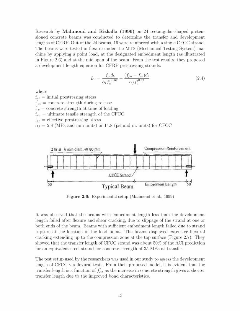
Research by Mahmoud and Rizkalla (1996) on 24 rectangular-shaped preten-sioned concrete beams was conducted to determine the transfer and developmentlengths of CFRP. Out of the 24 beams, 16 were reinforced with a single CFCC strand.The beams were tested in flexure under the MTS (Mechanical Testing System) ma-chine by applying a point load, at the designated embedment length (as illustratedin Figure 2.6) and at the mid span of the beam. From the test results, they proposeda development length equation for CFRP prestressing strands:
Ld =fpidb
αtf ′ci0.67 +
(fpu − fse)db
αff ′c0.67 (2.4)
wherefpi = initial prestressing stressf′ci = concrete strength during release
f′c = concrete strength at time of loading
fpu = ultimate tensile strength of the CFCCfpe = effective prestressing stressαf = 2.8 (MPa and mm units) or 14.8 (psi and in. units) for CFCC
Figure 2.6: Experimental setup (Mahmoud et al., 1999)
It was observed that the beams with embedment length less than the developmentlength failed after flexure and shear cracking, due to slippage of the strand at one orboth ends of the beam. Beams with sufficient embedment length failed due to strandrupture at the location of the load point. The beams displayed extensive flexuralcracking extending up to the compression zone at the top surface (Figure 2.7). Theyshowed that the transfer length of CFCC strand was about 50% of the ACI predictionfor an equivalent steel strand for concrete strength of 35 MPa at transfer.
The test setup used by the researchers was used in our study to assess the developmentlength of CFCC via flexural tests. From their proposed model, it is evident that thetransfer length is a function of f ′
ci, as the increase in concrete strength gives a shortertransfer length due to the improved bond characteristics.
13

Figure 2.7: Crack pattern observed by Zaki (Mahmoud and Rizkalla,1996)
Issa et al. (1993) performed transfer length testing on GFRP strands. The re-searchers used 6–in. x 4–in. specimens for two concentric 3/8–in. diameter S-2 glassepoxy strands. The strands were prestressed to 50% of their ultimate strength. Thetransfer length observed was 10 to 11 in., or, in other words, 28 times the nominaldiameter of the tendons. This demonstrates that the transfer length for FRP strandsis much shorter than for steel strands.
Taerwe et al. (1992) used transfer prisms to determine the transfer length of Aramidcomposite prestressing bars embedded in concrete prisms. Arapree AFRP bars witha sand coating were used in the program. The bars were 7.5 and 5.3 mm in diameter.The concrete strength used for the specimen construction was varied between 71.6and 81.5 MPa, and the strands were stressed to 50% of the ultimate tensile capacity.The transfer lengths measured in these tests were 16 to 38 times the bar diameter,depending on the type of coating on the bars. The study showed that the transferlength is affected by the finish on the prestressing strands.
The Transfer Prism is a test used to determine bond characteristics of reinforcements.This test can be used to measure the transfer length only, and its utility to determinethe flexural bond length is questionable (Domenico, 1995). In a typical transferprism, specimens are made by prestressing the tendons and casting concrete prismsof considerably small cross-sectional area, usually long with a square cross section.
The End Slip Method, also referred to as the “draw-in method”, is another techniquecommonly used to evaluate the transfer length of prestressing strands (Logan, 1997).This method is based on relating the amount of slippage measured at the end of thestrand upon the release of the prestressing force. First, the strand draw-in Δd iscalculated as follows:
Δd = δs − δc (2.5)
whereδs = the change in the strand’s length in the stress transfer zone due to prestress
14

releaseδc = the elastic shortening of the concrete in the stress transfer zone due to prestressrelease
By integrating the strains of the strand and the concrete along the transfer length,δs and δc can be calculated as follows:
Δd =
∫Lt
(Δεs −Δεc)dx (2.6)
In Equation 2.6, Δεs is the change in the strand strain due to prestress release, andΔεc is the change in the concrete strain due to prestress release. If the change in thestrand and concrete strain is linear, Equation 2.6 can be expressed in the following,simpler form:
Δd =fsiαEps
Lt (2.7)
In Equation 2.7, fsi is the initial stress in the strand, Eps is the Elastic Modulusof the strand, α is the stress distribution constant, and Lt is the transfer length.Balazs (1993) reported a value of 2 for parameter α in the case of constant stressdistribution and a value of 3 in the case of linear stress distribution. Typically, thestress distribution is assumed to be constant. Thus, the transfer length as given byAndrawes et al. (2009) can be calculated as follows:
Lt =2EpsΔd
fsi(2.8)
Domenico (1995) performed research on transfer length and bond characteristicsof CFCC strands by testing T–shaped concrete beams in flexure. The variables usedwere the diameter of the CFCC tendons, concrete cover and strength, and prestressinglevel. Domenico found that the measured transfer length was proportional to thediameter of the CFCC strands and the prestressing level applied. The transfer lengthof the CFCC strand was found to be in the range of 140 to 400 mm (5.5 to 15.7in.), which is much lower than the transfer length determined by using the ACI andAASHTO equations. The author also proposed an equation for transfer length whichis given by Equation 2.9:
Lt =fpeAp
80√
f ′ci
(2.9)
Grace (2003) designed and used CFRP as the primary reinforcing material in BridgeStreet Bridge, the first bridge in the USA to use CFRP. The span that uses the CFRPmaterial as reinforcement spans the Rouge River in Southfield, Michigan. This span
15

was constructed as shown in Figure 2.8, with one side using conventional girders, andthe other side using special carbon fiber reinforced beams to provide a side–by–sidecomparison.
Figure 2.8: Bridge Street Bridge plan view showing conventional spanA next to CFRP span B (Grace 2003)
The CFRP–reinforced bridge section consists of four (4) modified double-T girders,designed by Lawrence Technological University (LTU) and Hubbell, Roth and Clark,Inc. (HRC). The study involved long-term monitoring to evaluate the performance ofthe CFRP reinforcement. Monitoring devices were installed during construction ofthe span. The cross section of the double-T beam is shown in Figure 2.9.
Instead of steel, each web was reinforced with the following: ten (10) rows of three (3)10–mm bonded pretensioned CFRP tendons; six (6) rows of two (2) 12.5–mm non-prestressed CFCC strands; and one (1) row of three (3) 12.5–mm non-prestressedstrands in each web. The external longitudinal and transverse unbonded CFCCstrands provide post-tensioning. The longitudinal 40–mm CFCC strands are ex-ternally draped, and 60% of the final post-tensioning force was applied to the longi-tudinal strands before transporting the beam. Flexure testing was done on the beambefore the bridge span was constructed. The researchers observed that all 60 pre-
16

Figure 2.9: Carbon fiber reinforced double-T beam cross section(Grace, 2003)
tensioning strands failed, while the post-tensioning strands did not. At failure, thepost-tensioned strands were within 60% of their tensile capacity, and the ultimateload was 5.3 times the service load. The span was used for long–term monitoringof pretension load, concrete strain in the cross section, girder camber and deflection,external strand integrity, and strain of longitudinal external strands.
Grace (2007) presented the data obtained from monitoring the Bridge Street Bridgespan with CFRP reinforcement for a period of five (5) years (April 2001-July 2006),where it was concluded that the bridge spans were performing as expected. To monitorthe temperature distribution in the beams, thermistors were used in the embeddedvibrating wire strain gages. In addition to the data from the monitoring devices,manually–collected data was also obtained.
Significant fluctuations in the measured deflections have been observed, including er-ratic behavior by some of the sensors. The average mid-span deflections for BeamsC and G, after allowing for the flow of traffic, were observed to be about 23 and 14mm (0.98 and 0.55 in.), respectively. The researchers found that that the tempera-ture has no significant effect on the deflection of the beams. Furthermore, the studyconcluded that no discernible deviations had occurred beyond the variations due toseasonal temperature changes in the concrete strain and forces in the post-tensionedstrands over the five-year monitoring period. The successful implementation and the
17

performance of the CFCC in the Bridge Street Bridge show that CFCC is comparableto steel strands and holds a promising future as reinforcement in a bridge superstruc-ture. However, the performance of CFCC in a bridge substructure has yet to beassessed.
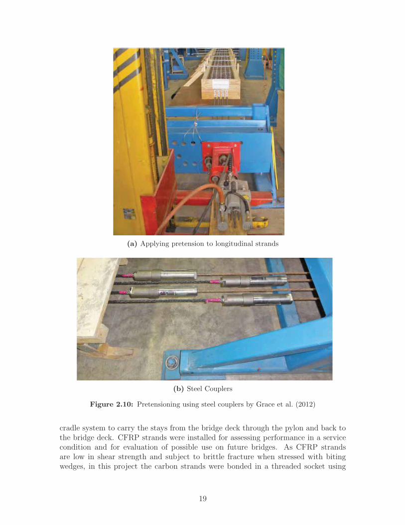
Three (3) single decked bulb-T beams were constructed and tested to failure byGraceet al. (2012). One beam, used as a control specimen, was prestressed and reinforcedwith steel strands. The second and third beams were prestressed and reinforced withCFCC and CFRP, respectively. The performance of the beams reinforced with CFCCand CFRP was found to be comparable with the performance of the control specimen.The prestressing force in the reinforcements was to a level of approximately 43, 37,and 57% of the ultimate strength of steel, CFCC, and CFRP, respectively. The stresslevel attributed to the CFCC and the CFRP strands was less than the maximumallowed by American Concrete Institute (ACI) 440.4R, which is 65%. The beamswere cast one (1) day after the prestressing was complete. A special mechanicaldevice, explained in Section 3.3, was used to facilitate the stressing of the CFCCstrands without damaging the ends of the strand. A hydraulic pump was used totension the strands (Figure 2.10).
The anchorage or coupling system provided with the CFCC strands was tested forcreep under joint research between Lawrence Technological University (LTU) andTokyo Rope. The release took place 14 days after concrete casting, and the releaseof the prestressing forces in the CFCC beam was performed by further pulling thestrand above the prestressing force and then untying the mechanical device. TheCFCC beam was designed to fail in compression by concrete crushing. The load wasapplied with a hydraulic actuator (Figure 2.11) and a two-point loading frame.
The performance of the beam was monitored through recording the deflection at themid span, strain readings in concrete and reinforcement, crack propagation, crackwidth, and crack pattern. The performance of the CFCC prestressed beams wasfound to be comparable to that of steel, as shown in Figure 2.12. Grace et al. (2012)concluded that the flexural load carrying capacity and the corresponding deflectionof the CFCC beam were 107% and 94% of those of the steel beam, respectively.
Although the research suggests that the performance of the CFCC strands was com-parable to steel strands, the prestressing level was below the recommended ACI pre-stress level (65% of Guaranteed Ultimate Tensile Strength (GUTS)). In the new studypresented herein, the CFCC was prestressed to 65% of GUTS.
2.6 Other CFCC Coupling Method
Rohleder et al. (2008) introduced the use of CFCC strands as cables as an emer-gency replacement for the Waldo–Hancock Bridge. The new bridge used an innovative
18
(a) Applying pretension to longitudinal strands
(b) Steel Couplers
Figure 2.10: Pretensioning using steel couplers by Grace et al. (2012)
cradle system to carry the stays from the bridge deck through the pylon and back tothe bridge deck. CFRP strands were installed for assessing performance in a servicecondition and for evaluation of possible use on future bridges. As CFRP strandsare low in shear strength and subject to brittle fracture when stressed with bitingwedges, in this project the carbon strands were bonded in a threaded socket using
19

Figure 2.11: Load setup for decked bulb-T beams (Grace et al., 2012)
(a) Steel-prestressed beam (b) CFCC-prestressed beam
Figure 2.12: Behavior of CFCC in comparison with steel strands. Load-Deflection curves for midspan shown. (Grace et al., 2012)
highly expansive grout (Figure 2.13). The annular spacing in between the socketwall and the strand was filled with a cementitious–based Highly Expansive Material(HEM), which exhibits a high degree of expansion during curing. The expansionof the material produces a confining pressure of approximately 11 ksi (75.85 MPa),locking the strand end and socket together.
Grace et al. (2003) showed that this confining pressure from the HEM is valuablefor avoiding creep concerns as might be found if an epoxy agent had been used toanchor the strand in the socket. For the research presented herein, the method usedby Grace et al. (2012) was followed to anchor the CFCC strands (Figure 2.10b), asit is also the anchoring method recommended by Tokyo Rope.
20

(a) Anchor sleeve with nut and strand
(b) Anchor sleeve with HEM
Figure 2.13: HEM coupling method (Rohleder et al., 2008)
2.7 Flexure Test
A flexure test can be used to determine the development length in prestressed concretemembers. The test is an iterative process wherein it is often required to evaluate theposition of the applied load. The distance between the applied load and the endof the beam can be varied to determine the development length. If the beam failsdue to failure of the bond between the strand and the concrete, then this distanceis increased, and the test is repeated. Otherwise, if the beam fails in flexure, thisdistance is decreased. This process is repeated until bond failure and flexure failureoccur simultaneously. When this scenario occurs, this distance is considered to bethe development length.
Figure 2.14 shows a general setup of a three–point bending test used by Andraweset al. (2009). If the beam fails in flexure, the load is moved to the left (direction i),and if the beam fails due to bond failure, the load is moved to the right (direction ii).
Abalo et al. (2010) performed testing at the FDOT Marcus H. Ansley StructuresResearch Center to evaluate the use of CFRP mesh in place of spiral ties or conven-tional reinforcement spirals for a 24–in. square prestressed concrete pile. A controlpile was cast along with the test pile for comparison. Figure 2.15 shows the cross sec-tions of the control and CFRP piles. The control pile was tested earlier to comparethe actual capacity to the theoretical capacity of the CFRP pile. The control pilewas also a 24–in. square prestressed concrete pile; however, it had 16 0.6–in. diameterlow-relaxation strands in a square pattern with W3.4 spiral ties. Both piles were 40–ftlong. Strain gages were used to measure concrete strain on the top fiber towards thecenter of the pile, and ten (10) displacement gages were placed along the length ofthe pile. The control and CFRP pile test setups were similar except for the numberof strain gages used.
A single point load was applied to a spreader beam that consisted of two (2) steelI-beams whose reactions provided the two (2) point loads applied to the pile. The
21

Figure 2.14: Flexure test used to evaluate development length (An-drawes et al., 2009)
(a) Control pile (b) CFRP pile
Figure 2.15: Pile sections (Abalo et al., 2010)
load was applied until failure, and the CFRP pile experienced a compressive failureat the top. The ratio of actual-to-theoretical moment capacity for the CFRP pile was1.27, compared to 1.21 for the control pile.
Based on the research, a conclusion can be made that the performance of the pileusing CFRP meshing was higher than that of the control pile. A similar test setup wasused in the study presented herein to assess the flexural behavior of CFCC–prestressedpiles.
To summarize, there has been a lot of research on the performance of CFRP strands
22

in beams. The purpose of the research presented herein was to investigate the per-formance of CFCC strands in 24–in. square piles, so as to evaluate the feasibility ofreplacing the steel in conventional piles used in Florida Department of Transportationbridge construction projects.
23

CHAPTER 3
MATERIALS ANDINSTRUMENTATION
3.1 Introduction
This research involved the precasting and testing of five (5) CFCC–prestressed con-crete piles having a cross section of 24 in. x 24 in., with three (3) piles being 40–ft longand two (2) piles being 100–ft long. The piles were precast at Gate Precast Company(GATE) in Jacksonville, Florida. The various tests were performed at GATE, FDOTMarcus H. Ansley Structures Research Center, and at a bridge construction site inVolusia County, Florida. This chapter describes the characteristics and properties ofthe materials used to construct the piles and the instrumentation used to test them.
3.2 Prestressing Strands
CFCC, manufactured by Tokyo Rope, was used as the prestressing material in thepiles. CFCC is a composite of fiber and a fiber bond; the fiber used to provide bond isusually epoxy. Care must be taken to protect the strands from damage, deformation,and sudden shocks caused by heavy or hard objects. Strand diameters of 12.5 mm (0.5in.) and 15.2 mm (0.6 in.) were used for longitudinal prestressing in the initial andfinal precasting attempts, respectively, and a CFCC wire with diameter 5.0 mm (0.2in.) was used for transverse spiral reinforcement. As reported by the manufacturer,the strands and wire have effective cross–sectional areas of 76.0 mm2 (0.118 in2),115.6 mm2 (0.179 in2), and 15.2 mm2 (0.0236 in2), respectively. The GUTS is 184 kN(41.4 k) for the 12.5–mm diameter strands, 270 kN (60.7 k) for the 15.2–mm strands,and 38 kN (8.54 k) for the 5.0–mm wire. The strands’ modulus of elasticity 155 GPa(22,480 ksi), and the ultimate tensile strain is 1.6%; the modulus of elasticity for thewire is 167 GPa (24,221 ksi). The stress-strain relationship of CFCC strand is linear
24
up to failure. Other characteristics of CFCC are mentioned in Section 2.3 and inAppendix A.
For the final precasting attempt, conventional 0.6–in. diameter steel strands werecoupled with the CFCC to facilitate stressing. They were seven–wire, 270–ksi (1.86–GPa), low–relaxation strands conforming to ASTM A416 specifications. Their nomi-nal cross–sectional area is 0.217 in2 (140 mm2), and the modulus of elasticity is 28,500ksi (196 GPa).
3.3 Coupling Device Anchorage System
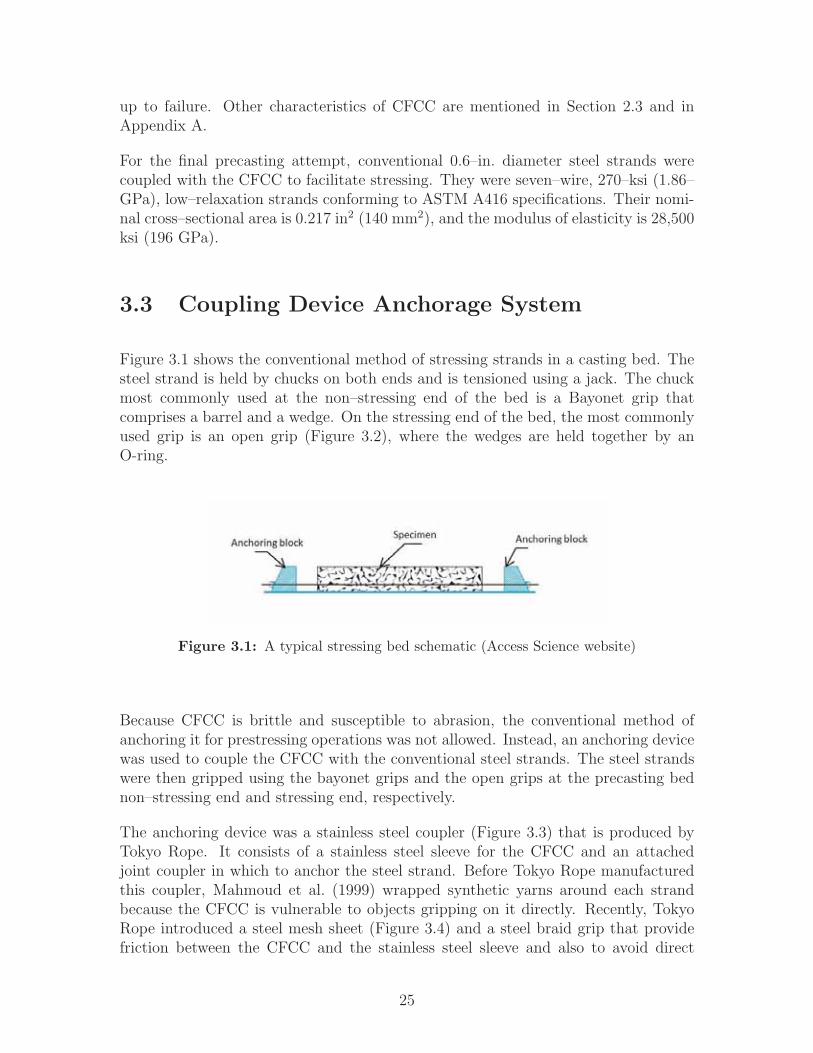
Figure 3.1 shows the conventional method of stressing strands in a casting bed. Thesteel strand is held by chucks on both ends and is tensioned using a jack. The chuckmost commonly used at the non–stressing end of the bed is a Bayonet grip thatcomprises a barrel and a wedge. On the stressing end of the bed, the most commonlyused grip is an open grip (Figure 3.2), where the wedges are held together by anO-ring.
Figure 3.1: A typical stressing bed schematic (Access Science website)
Because CFCC is brittle and susceptible to abrasion, the conventional method ofanchoring it for prestressing operations was not allowed. Instead, an anchoring devicewas used to couple the CFCC with the conventional steel strands. The steel strandswere then gripped using the bayonet grips and the open grips at the precasting bednon–stressing end and stressing end, respectively.
The anchoring device was a stainless steel coupler (Figure 3.3) that is produced byTokyo Rope. It consists of a stainless steel sleeve for the CFCC and an attachedjoint coupler in which to anchor the steel strand. Before Tokyo Rope manufacturedthis coupler, Mahmoud et al. (1999) wrapped synthetic yarns around each strandbecause the CFCC is vulnerable to objects gripping on it directly. Recently, TokyoRope introduced a steel mesh sheet (Figure 3.4) and a steel braid grip that providefriction between the CFCC and the stainless steel sleeve and also to avoid direct
25

Figure 3.2: Open grip (Source: CCL pretensioning systems website)
contact of the wedges with the CFCC, thus avoiding mechanical abrasion. The meshsheet comprises interlocked layers of stainless steel sheets and Polinet sheets. Thisprovides adequate buffer to the CFCC strands and resists the bite from the wedgesduring seating, thus protecting the strand from getting damaged. The braided gripprovides a second layer of buffering while creating frictional forces against the wedges.To anchor the conventional steel strand to the coupler, a chuck is used.
Figure 3.3: Tokyo Rope coupling device (Tokyo Rope CFCC handlingmanual)
26

Figure 3.4: Construction of buffer material (Tokyo Rope)
Tokyo Rope currently produces couplers for 0.6–in. diameter strands. This newly–developed anchoring device was tested for creep under joint research between LawrenceTechnological University (LTU) and Tokyo Rope. The installation procedure for theanchoring device is explained in Chapter 4, and Tokyo Rope’s installation instructionsare included in Appendix A.
3.4 Concrete
Self–consolidating concrete (SCC) was used in this research program. SCC is a highly–workable concrete that flows under its own weight through densely–reinforced orcomplex structural elements. The benefits of using SCC include:
1. Improved constructability
2. A smooth finished surface
3. Eliminated need for mechanical vibration
4. It easily fills complex-shaped formwork.
For a concrete mix to be considered as self–consolidating concrete, the Precast/PrestressedConcrete Institute (PCI) suggests a minimum of three physical properties:
1. Flowability
2. Passing ability
3. Resistance to segregation
To achieve the high flowability and stability characteristics of SCC, typical mixeshave a higher paste volume, less or smaller coarse aggregate, and higher sand-to-coarse aggregate ratios than conventional mixtures. Figure 3.5 compares the volumepercentage of the constituents used in SCC and those used in traditional concrete.
27

Previous studies have demonstrated that hardened SCC shares similar mechanicalproperties with conventional concrete in terms of strength and modulus of elasticity(Persson, 2001). However, SCC has greater concrete shrinkage because of its higherpaste or fines content.
Figure 3.5: Typical volume percentage of constituents in SCC and tra-ditional concrete (Andrawes et al., 2009)
Andrawes et al. (2009) researched the bond of SCC with steel strand, and he con-cluded that SCC does not affect the strand’s transfer or development length and iscomparable to conventional concrete and its strength.
GATE mixed the SCC for the piles, and they measured the 28-day cylinder strengthto be 8640 psi (59.6 MPa). The aggregates in the mix design were 67 Rock, Sand,STI Flyash, and Glenium 7700. The water–to–cement ratio was 0.34, and the densitywas 142.3 lb/ft3. The concrete mix properties are in Appendix B.
3.5 Instrumentation
3.5.1 Strain Gages
This research involved concrete strain measurement during transfer and during flex-ural and development length tests. For this purpose, strain gage model KC–60–120–A1–11 (L1M2R), manufactured by KYOWA Electronic Instruments Co., Ltd., wasused (see Figure 3.6),
where
28

60 = length of the strain gage (mm)120 = resistance of the gage (Ω)L1M2R = 2 lead wires of length 1 m each
Figure 3.6: Strain gage schematic (Kyowa Strain Gage Manual)
The two (2) lead wires come connected to the strain gage from the supplier, for ease ofconnecting the gages to the data acquisition system. Otherwise, the lead wires haveto be soldered to the gage, which is a time–consuming process. This type of straingage can be easily adhered to concrete by using glue, and some initial preparationis required before application, which is explained in Section 5.1. Chapter 5 providesdetails on the strain gage layout for each stage of testing and type of test performed.
3.5.2 Deflection Gages
Non–contact displacement gages, provided by the FDOT Structures Research Center,were used for the flexural and development length tests on the 40–ft piles. Thedisplacement gages are easy to install and can project the laser in areas where contactdisplacement gages cannot reach. Chapter 5 provides details on the displacement gagelayout for each type of test performed.
3.5.3 Embedded Data Collectors (EDC)
To monitor the two (2) 100–ft–long piles during driving operations, Embedded DataCollectors (EDC), shown in Figure 3.7, were pre-installed in the piles before they werecast at GATE. The EDC system was provided and installed by Applied FoundationTesting, Inc. (AFT). AFT also provided personnel on site during pile driving andinterpreted the results. The installation procedure is explained in Chapter 4.
Embedded Data Collectors are strain transducers and accelerometers that are em-bedded in a concrete member. The EDC system was developed as a result of theFDOT project, “Estimating Driven Pile Capacities during Construction” (Herreraet al., 2009). Before EDC was developed, pile monitoring during driving was done
29

Figure 3.7: Typical EDC set of instruments (Source: FDOT)
with a Pile Driving Analyzer® (PDA). Because the PDA requires the user to assumea constant damping factor for static resistance estimates in the field, and because sig-nal matching analyses (CAPWAP) do not produce unique solutions, FDOT soughtan alternative method to calculate static resistance from dynamic load test results.Hence, the FDOT studies were conducted on the use of EDC as a standard method tomonitor piles during driving. The EDC system estimates soil damping for every blowduring driving. The ability to monitor the pile specimen over a long period of time(several months or years) is another advantage of EDC. In the research by Herreraet al. (2009), EDC performance was compared to PDA and CAPWAP on a databasecompiled by FDOT. Herrera observed that the EDC provides results that are on anaverage within 15 percent of PDA and CAPWAP estimated static resistance.
3.5.4 Pile Driving Analyzer® (PDA)
The Pile Driving Analyzer® (PDA) system was used to monitor the two (2) 100–ft–long piles during driving operations. The PDA uses accelerometers and straintransducers to continuously measure pile-top forces and velocities. It is used to mon-itor stresses in the pile during driving; accordingly, adjustments can be made to thecushion and hammer impact force to prevent damage to the pile. Measurementsrecorded during driving are also used to calculate the pile driving resistance, as wellas the pile’s static bearing capacity. FDOT provided and installed the PDA systemand interpreted the results. GRL Engineers, Inc. (GRL) was also on site to providean analysis and expertise.
30

CHAPTER 4
TEST SPECIMEN PRODUCTION
4.1 Introduction
This research involved the precasting and testing of five (5) CFCC-prestressed con-crete piles. This chapter describes the casting setup and the different methods usedto stress the strands, and comparisons to conventional methods are made.
Tokyo Rope’s coupler installation procedure, as well as stressing procedures and cou-pler arrangements similar to those used by Grace et al. (2012), was used for thisresearch. This was the first instance that couplers were used by FDOT, and hencean initial session was conducted at the Marcus H. Ansley Structures Research Centerto demonstrate the installation procedure for the coupling device. This session alsoillustrated to the precaster, Gate Precast Company, the techniques for installing andtensioning a CFCC strand.
Later, on July 22–26, 2013, the research team from the FAMU-FSU College of Engi-neering joined with Tokyo Rope at GATE’s precasting yard in Jacksonville, Florida,to precast the five (5) pile specimens. There, Tokyo Rope installed the 40 couplers —20 at each end of the precasting bed. GATE stressed the set of 20 CFCC strands, tiedCFCC spiral reinforcement, and cast the concrete. FAMU-FSU provided assistancewhenever needed and oversaw the efforts for accordance with the design and researchgoals.
This chapter provides details of these efforts, and Appendix H includes several photosof the coupler installation, CFCC strand stressing, CFCC spiral installation, and pilecasting.
31
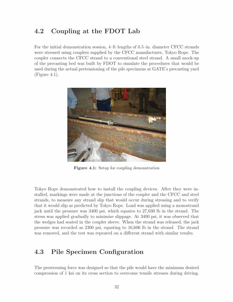
4.2 Coupling at the FDOT Lab
For the initial demonstration session, 4–ft lengths of 0.5–in. diameter CFCC strandswere stressed using couplers supplied by the CFCC manufacturer, Tokyo Rope. Thecoupler connects the CFCC strand to a conventional steel strand. A small mock-upof the precasting bed was built by FDOT to simulate the procedures that would beused during the actual pretensioning of the pile specimens at GATE’s precasting yard(Figure 4.1).
Figure 4.1: Setup for coupling demonstration
Tokyo Rope demonstrated how to install the coupling devices. After they were in-stalled, markings were made at the junctions of the coupler and the CFCC and steelstrands, to measure any strand slip that would occur during stressing and to verifythat it would slip as predicted by Tokyo Rope. Load was applied using a monostrandjack until the pressure was 3400 psi, which equates to 27,030 lb in the strand. Thestress was applied gradually to minimize slippage. At 3400 psi, it was observed thatthe wedges had seated in the coupler sleeve. When the strand was released, the jackpressure was recorded as 2300 psi, equating to 16,606 lb in the strand. The strandwas removed, and the test was repeated on a different strand with similar results.
4.3 Pile Specimen Configuration
The prestressing force was designed so that the pile would have the minimum desiredcompression of 1 ksi on its cross section to overcome tensile stresses during driving.
32

The prestressing strand pattern was based on FDOT’s standard details for a 24–in. square pile with 20 0.6–in. diameter (15.2–mm) strands (Figure 4.2a). The 20–strand option was chosen because of GATE’s casting bed strand template. Thespirals were 5.0–mm diameter (0.2–in.) CFCC, with approximate dimensions shownin Figure 4.2b. The number of turns and pitches for the CFCC spirals was basedon FDOT standards for conventional steel spirals (Figure 4.3), which is designed toprovide confinement to the concrete core and to avoid premature failure at the endsdue to prestress release and impact load during driving. More details of the piles areprovided in Appendix C.
(a) Section (b) Spirals
Figure 4.2: Section view of the pile specimens. (See Appendices A andC for manufactured dimensions.)
Figure 4.3: FDOT standard pile details
4.4 Prestressing Losses
PCI Design Handbook (PCI, 2010) edition, Chapter 5, explains the prestressing losscalculations for a prestressed concrete member. This enables the designer to estimatethe prestressing losses rather than using a lump–sum value. The equations provide
33

realistic values for normal design conditions. These equations were applied to calcu-late the prestress losses for the five (5) pile specimens and resulted in a total prestressloss of 8.8% for each of the 16 strands. The four (4) corner strands that were initiallystressed to only 5 k had much greater losses (61.6%) because the elastic shortening,creep, and shrinkage losses due to all the strands being stressed were disproportionalto the small initial stress (See Appendix D). The calculations for the various lossesare described below.
The total losses are due to elastic shortening (ES), creep of concrete (CR), shrinkageof concrete (SH) and relaxation of the strands (RE):
TL = ES + CR + SH +RE (4.1)
Losses due to elastic shortening, in psi, are calculated as:
ES =KesEpsfcir
Eci
(4.2)
whereKes = 1.0 for pretensioned componentsEps = modulus of elasticity of prestressing strands (psi)Eci = modulus of elasticity of concrete at the time prestress is applied (psi)fcir = net compressive stress in concrete at center of gravity of prestressing forceimmediately after the prestress has been applied to the concrete (psi)
where
fcir = Kcir(Pi
Ag
+Pie
2
Ig)− Mge
Ig(4.3)
whereKcir = 0.9 for pretensioned componentsPi = initial prestress force (lb)e = eccentricity of center of gravity of tendons with respect to center of gravity ofconcrete at the cross section considered (in.)Ag = area of gross concrete section at the cross section considered (in2)Ig = moment of inertia of gross concrete section at the cross section considered (in4)Mg = bending moment due to dead weight of prestressed component and any otherpermanent loads in place at the time of prestressing (lb-in.)
Losses due to creep of concrete, in psi, are calculated as:
CR = Kcr(Eps
Ec
(fcir − fcds)) (4.4)
34

whereKcr = 2.0 normal–weight concretefcds = stress in concrete at center of gravity of prestressing force due to all super-imposed, permanent dead loads that are applied to the member after it has beenprestressed (psi)Ec = modulus of elasticity of concrete at 28 days (psi)
where
fcds =Msd(e)
Ig(4.5)
whereMsd = moment due to all superimposed, permanent dead load and sustained loadapplied after prestressing (lb-in.)
Losses due to shrinkage of concrete, in psi, are calculated as:
SH = (8.2 ∗ 10−6)KshEps(1− 0.06V
S)(100−RH) (4.6)
whereKsh = 1.0 for pretensioned componentsVS= volume-to-surface ratio
RH = average ambient relative humidity
Losses due to relaxation of strands, in psi, are calculated as:
RE = [Kre − J(SH + CR + ES)]C (4.7)
where values of Kre and J are taken from Table 5.7.1 in PCI (2010), and values ofcoefficient C are taken from Table 5.7.2.
4.5 Pile Casting Bed Setup
4.5.1 Stressing Forces
According to the ACI specifications for CFRP strands, CFCC should be stressed tono more than 65% of GUTS. For the 15.2–mm diameter strands, GUTS is equal to270 kN (60.7 kips). However, GATE’s casting bed was designed to hold a maximumcompressive force of 684 kips, which is not enough strength if all 20 strands were
35

stressed to 65% of GUTS. To keep the total compressive force under the capacity ofthe casting bed, one of the options considered was to stress all the strands to less than65%. The option chosen, however, was to stress the four (4) corner strands to 8.2%of GUTS and to stress the remaining 16 strands to 65% of GUTS. This would permitthe CFCC’s performance to be assessed at ACI’s recommended maximum stress level.Hence, the jacking force for each of the 16 strands was 39.45 kips (65% of GUTS), andthe jacking force for each of the four (4) corner strands was 5 kips (8.2% of GUTS)— for a total compressive force of 651.2 kips.
4.5.2 Wooden Headers
CFCC strands are not as strong in shear as steel strands, approximately half asmuch, and are susceptible to damage from hard-edged objects in abrasion. To avoiddamaging the CFCCs, GATE’s conventional steel headers were replaced with wooden(0.5–in.–thick plywood) headers that were built at the casting yard (Figure 4.4).Twenty (20) holes of 0.7–in. diameter were drilled in the headers to accommodatethe CFCC strands. The wooden headers were placed at every pile–end location.Additional headers were placed at each end (at the stressing and non–stressing ends)of the bed, to be used for casting 5–ft–long concrete blocks that would secure thestrands as a measure of safety after stressing.
(a) Conventional Steel Header
(b) Wooden Header
Figure 4.4: Steel header replaced with wooden header
36

4.5.3 Prestressing Bed Layout
The prestressing bed was a self-stressing form, with a total length of 440 feet. Aschematic is shown in Figure 4.5. The distance between the concrete block at thestressing end and Pile ′1′ was 1 ft, and similarly the distance between the concreteblock at the non–stressing end and Pile ′5′ was 1 ft. The end–to–end distance betweenadjacent piles was 1 ft, to provide enough room to cut the CFCCs. Because of thecoupling devices that were used, additional length of CFCC strands was considered,which is explained in the next section.
Figure 4.5: Stressing bed schematic at Gate Precast Company
4.6 Strand Installation
The 5–mm diameter CFCC spirals were delivered in five (5) bundles, one (1) for eachpile. The bundles were placed at each pile location, to be put in the final positiononce the prestressing operations were complete. The CFCC strands were deliveredto GATE in spools (Figure 4.6). They were pulled from the spool and along thelength of the casting bed, while being fed through the headers. GATE used typicalprocedures to pull the strands, with the exception of their pulling one strand at atime by hand instead of machine-pulling several at a time.
Each strand was cut to a length of 360 ft before another one was pulled from thespool. This length accounted for the prestressing bed setup, so the strand wouldbe long enough for the total pile length, the concrete blocks, the headers, and theadditional length needed to avoid coupler interaction during stressing (as discussedin the next section).
37

Figure 4.6: Assembly to lay strands
4.7 Coupler Staggering
Before the couplers were installed, it was necessary to consider the CFCC strandelongation and the seating losses in the coupler as explained in Section 4.2. Thecouplers were installed in a staggered pattern, to avoid any coupler interaction thatcould result from the strands elongating during tensioning. The couplers were stag-gered at 3–ft increments. The strands were stressed starting with the coupler closestto the stressing jack and extending 8 ft from the end of the pile, proceeding to thecouplers extending 5 ft, and finally to the couplers extending 2 ft. Figure 4.7 showsthe stagger pattern at the stressing and non–stressing ends of the prestressing bed,and Figure 4.8 shows a plan view at each end.
38
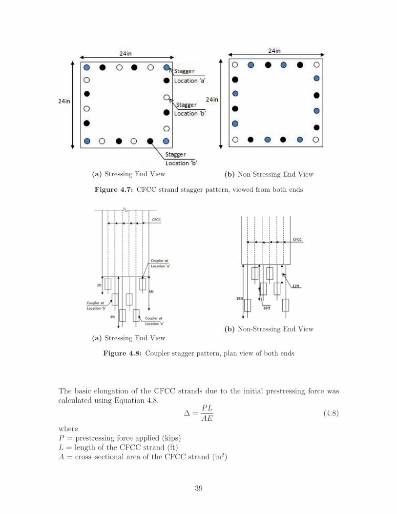
(a) Stressing End View (b) Non-Stressing End View
Figure 4.7: CFCC strand stagger pattern, viewed from both ends
(a) Stressing End View
(b) Non-Stressing End View
Figure 4.8: Coupler stagger pattern, plan view of both ends
The basic elongation of the CFCC strands due to the initial prestressing force wascalculated using Equation 4.8.
Δ =PL
AE(4.8)
whereP = prestressing force applied (kips)L = length of the CFCC strand (ft)A = cross–sectional area of the CFCC strand (in2)
39

E = modulus of elasticity of the strand (ksi)
In addition to the basic elongation, an abutment rotation of 0.25 in., anchor sets of0.125 in. and 0.375 in. for the non-stressing end and stressing end, respectively, alongwith seating losses of the steel strand’s and CFCC’s wedges in the coupler, were takeninto account. The seating in each coupler was assumed to be 0.125 in. for the steelstrand and 2.165 in. for the CFCC strand per the manufacturer. The elongation ofthe steel strands were also considered.
4.8 Coupler Installation Procedures
The couplers were installed by Tokyo Rope. Tokyo Rope’s full instructions are in-cluded in Appendix A and are summarized below.
4.8.1 Setting the Anchoring Device
1. Wrapping the Buffer Material
The buffer material explained in Chapter 3 was wrapped over the end of theCFCC strand to be anchored. The wrapping was spiraled over the strand,carefully following the CFCC’s direction of twist, so that during tensioning, thestrand and the buffer material would act homogeneously (see Figure 4.9).
Figure 4.9: Wrapping the buffer material (Source: Tokyo Rope)
According to Tokyo Rope specifications, the buffer material should extend upto 160 mm from the end of the CFCC to be anchored so as to provide enougharea for the wedges to seat.
2. Spray Molybdenum
40

The sleeve was lubricated with molybdenum spray (Figure 4.10) to reduce thefriction between the wedges and the sleeve during wedge seating. Although
Figure 4.10: Spraying molybdenum on the sleeves (Source: TokyoRope)
the amount of molybdenum to be sprayed on the sleeve was specified by TokyoRope, the sleeves were sprayed until the inside surface was fully covered.The molybdenum spray is an air–drying, solid film lubricant containingmolybdenum disulfide and a binder, so it adheres to many surfaces and doesnot easily rub off. It forms a thin, dry but “slippery” film of solid lubricantsand performs under extremely heavy loads up to 10,000 psi. The molybdenumspray for this research was supplied by Tokyo Rope.
3. Insert the Sleeve and Install the Braided Grip
After spraying the sleeve with the molybdenum lubricant and letting it dry(usually less than a minute), the CFCC strand (which is wrapped with themesh sheet) was inserted into the sleeve. The mesh sheet buffer material wasthen covered with the braided grip (Figure 4.11).
Figure 4.11: Installing sleeve and the braided grip
The braided grip was first compressed manually, such that the grip’s diameterincreased for the ease of sliding it over the mesh sheet. Once it enveloped themesh sheet, the braided grip was drawn tightly towards the end of CFCC toeliminate the excess diameter if any, such that the braided grip wrapped themesh sheet without any wrinkles. An electrical tape was fixed to both the endsof the braided grip and mesh sheet to protect the installer from any sharp edges.
41

4. Check the Installation
It was ensured that the wrapping of the buffer material followed the specifica-tions provided by Tokyo Rope:
• Tape–to–tape length needs to be over 155 mm because the length of thewedge is 155 mm
• Check if the braided grip has no wrinkles and is tightly wrapped
• The spiral wrapping of the mesh sheet should not have any gap betweenthe spirals
4.8.2 Setting Wedges and Sleeve Toward CFCC
Figure 4.12 shows the steps to set the wedges and sleeve for the CFCC. Once the
(a) Step 1 (b) Step 2 (c) Step 3
Figure 4.12: Wedge setup
checks for the buffer material were verified, the molybdenum spray was applied onthe outer surface of the wedges until they were completely covered with a thin film ofthe lubricant, to provide ease of wedge seating. The wedges were placed on the CFCCstrand wrapped with the buffering material, such that 60 mm of the strand end wasextending beyond the larger diameter of the wedge. The wedges were provided withan O-ring so that they remained in place.
The wedge position was checked for the following:
1. The wedge position should not overlap with the electrical tape that is wrappedaround the ends of the buffer material.
2. The wedges should not have any gaps between them.
The wedges were inserted into the sleeve:
A pneumatic jack provided by Tokyo Rope was used to provide a consistent pene-tration of all four (4) parts of the wedge into the sleeve, as shown in Figure 4.13.A 55–mm mark was made on the wedge from the larger end of the wedge, and that
42

is the point to which the wedge was penetrated in to the sleeve. If the wedges areinconsistently installed in the sleeve, there are chances of improper seating of thewedges, thus providing an uneven grip on the CFCC strand. After the mark wasmade, the pneumatic jack (Figure 4.13) was used to push the wedges into the sleeve,with a pressure of about 20 MPa (3 ksi).
Figure 4.13: Wedge installation
4.8.3 Finishing the Coupler Installation
The coupler installation was finished in the two steps described below.
1. Attaching the wedges and the coupler to the steel strand:
A standard open grip, shown in Figure 3.2, was used to wedge the steel strandin the coupler. The coupler is provided with a hole which allows the steel strandto be inserted in one end (Figure 4.14). After the steel strand was inserted intothe coupler, the open grip was installed on it and was pulled back inside thecoupler, so that anchoring of the steel strand was complete.
Figure 4.14: Steel strand installation
2. Joining the CFCC to the steel strand:
43
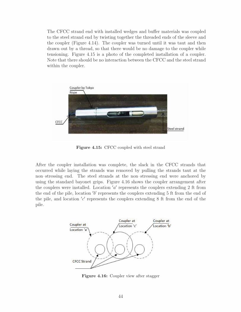
The CFCC strand end with installed wedges and buffer materials was coupledto the steel strand end by twisting together the threaded ends of the sleeve andthe coupler (Figure 4.14). The coupler was turned until it was taut and thendrawn out by a thread, so that there would be no damage to the coupler whiletensioning. Figure 4.15 is a photo of the completed installation of a coupler.Note that there should be no interaction between the CFCC and the steel strandwithin the coupler.
Figure 4.15: CFCC coupled with steel strand
After the coupler installation was complete, the slack in the CFCC strands thatoccurred while laying the strands was removed by pulling the strands taut at thenon–stressing end. The steel strands at the non–stressing end were anchored byusing the standard bayonet grips. Figure 4.16 shows the coupler arrangement afterthe couplers were installed. Location ′a′ represents the couplers extending 2 ft fromthe end of the pile, location ′b′ represents the couplers extending 5 ft from the end ofthe pile, and location ′c′ represents the couplers extending 8 ft from the end of thepile.
Figure 4.16: Coupler view after stagger
44

4.9 Stressing the Strands
The stressing pattern was different than for conventional steel strand stressing. Allthe strands were stressed to a force of 5 k during the initial prestressing, and the cornerstrands were not stressed more thereafter. The remaining 16 strands were stressedin the sequence shown in Figure 4.17. GATE measured the stressing force during allpretensioning operations and recorded it after each strand was fully stressed.
Figure 4.17: Stressing sequence, at stressing end, looking towards pile
The expected combined elongation of the CFCC strands and steel strands was lessthan 50 in. The hydraulic jack had a stroke capacity of 72 in. and therefore wouldnot need to be repositioned to complete the stressing. Hence, there was no need tocut any steel strand ends during the stressing operation. Because the CFCC wascoupled with the steel strand, Tokyo Rope advised the precaster to stress each strandgradually. The suggested approximate time to stress one strand to a force of 39.45 kwas 3 minutes. This would allow the wedges in the coupler to seat without causingany slippage of the strands.
The prestressing force was applied using a hydraulic monostrand jack, and the strandswere locked using open grips at the stressing end so that the force would be maintainedafter jacking. For the initial stressing, all 20 strands were stressed to a force of 5 k,and the corner strands were not stressed more thereafter. After the initial stressingwas complete, the CFCC strands were checked to ensure that there was not excessslack, and the integrity of the coupler device was checked. Markings were made onthe CFCC strands at the edge of the couplers to denote any slippage. Figure 4.18
45

illustrates the coupler stagger pattern after the completion of initial stressing.
Figure 4.18: Staggered couplers after initial pretensioning
Figure 4.19 shows the target force for each strand, and Table 4.1 shows the measuredforce and elongation for each strand. During the stressing process, after each strandtensioning was complete, elongation of strands was recorded by measuring from a pre–marked spot on the strand to the end of the jack. The measured elongations rangedfrom 463
4in. to 50 in., which was close to the expected 471
4in. The elongations of
strands 2, 3, and 4 were higher than the calculated elongation, likely because of initialexcess slack in the strand due to the weight of the coupler.
After the completion of stressing, self–consolidating concrete was used to cast theconcrete blocks between the pile ends and casting bed ends. This was a measure ofsafety to secure the stressed strands. The concrete was mixed at GATE and wassupplemented with an accelerating agent, so that the concrete blocks would curefaster.
46

(a) Target forces(b) Strand numbers
Figure 4.19: Target forces and strand numbers at stressing end
Table 4.1: Force and elongation measurements
Strand Force in Calculated ObservedNo. Strand Elongation Elongation
lb in. in.1 5000 NA NA2 39460 471
450
3 39490 4714
4934
4 39460 4714
485 39430 471
4471
2
6 5000 NA NA7 39460 471
4473
4
8 39460 4714
4634
9 39460 4714
4714
10 39440 4714
4712
11 5000 NA NA12 39450 471
4471
4
13 39450 4714
4634
14 39450 4714
4714
15 39470 4714
4634
16 5000 NA NA17 39460 471
448
18 39440 4714
4634
19 39470 4714
4714
20 39510 4714
4714
47

4.10 Installation of Spirals and EDC
The CFCC spirals, which were placed near their respective locations in the piles beforethe stressing operations began, were tied in their final position to the CFCC strandswith plastic zip ties (Figure 4.20). The spirals at the locations where Embedded DataCollectors were to be installed were temporarily left untied, to provide enough spaceto install the EDC, after which the spirals were tied. Lifting hooks were installed inaccordance with FDOT standards.
Figure 4.20: Installation of stirrups (Source: ACI)
Embedded Data Collectors were installed in the two (2) 100–ft piles, for the purposeof monitoring the piles during driving. Applied Foundation Testing, Inc. (AFT)provided and installed the Embedded Data Collectors, as follows:
1. EDCs were installed at two (2) pile widths (48 in.) from the head of the pileand at one pile width (24 in.) from the tip of the pile.
2. An additional EDC was installed at the center of the other two (2) EDCs tomonitor the strain in the mid span during driving.
3. Cables were run through the piles for enabling the connection between the three(3) sets of EDCs.
4. The cables were tied to the strands using zip ties, making sure that the cableswould not be subjected to any damage while placing concrete.
48

The instrument set located in the center was kept clear of the lifting hooks, at 48in. and 51 in. from the pile head for Pile No. 1 and Pile No. 2, respectively (refer toFigure 4.5 for casting bed layout). The spirals in the vicinity of the EDCs were tiedto the CFCC strands after the EDC installation was complete. Figure 4.21 showsthe EDC secured to the CFCC strands. The EDC was fixed using a rubber materialto prevent the hard edge of the steel frame from interacting with the strands and tominimize any steel and carbon interaction. The entire setup was checked for quality
Figure 4.21: EDC clamped with a rubber material
by GATE and the researchers before the concrete was placed. Once the piles werecast and cured as described in the next section, the battery for the EDC system wasdisconnected. The battery was reconnected several months later, when the piles weredriven at the construction site.
4.11 Concrete Placement
Not typically used for piles, a self–consolidating concrete mix was used to avoid theneed to use a mechanical vibrator. This was desired because the CFCC strands aresusceptible to abrasion and damage if a conventional mechanical vibrator is used. Asper Tokyo Rope’s standards, a vibrator with a rubber tip can be used to consolidatethe concrete in a member that contains CFCC, or a mechanical vibrator with norubber wrapping can be used in cases where the spacing between the CFCCs is largerthan the diameter of the vibrator head so that there is no interaction between the
49

vibrator head and the CFCC strands. Instead, self–consolidating concrete was usedso that a vibrator would not be needed during placement operations (Figure 4.22).This would avoid altogether the potential of impacting the CFCC with a vibrator.
Figure 4.22: Casting using SCC
Accelerants were added to the concrete for faster curing. To cast all five (5) piles, four(4) truckloads of concrete were placed. The top surface of the concrete was leveled toa smooth finish. Once the casting was complete, a plastic cover was placed over thebed to facilitate a uniform curing temperature, as shown in Figure 4.23. Steam curingwas not allowed because the temperature could have affected the couplers. Accordingto Tokyo Rope, slippage of a strand in the coupler occurs at around 140oF.
Seven (7) 4-in. x 8-in. cylinders were made, to test for concrete strength after 24 hours(to determine if the strands could be released) and at the times of the flexure testsand pile driving tests. The next day, the strain gages were installed for the purposeof the transfer length tests described in the next chapter.
4.12 Stress Release
To release the strand force into the piles, the strands were then cut in the sequenceshown in Figure 4.24. Figure 4.25 shows the tools used to cut the steel and CFCCstrands, respectively.
50
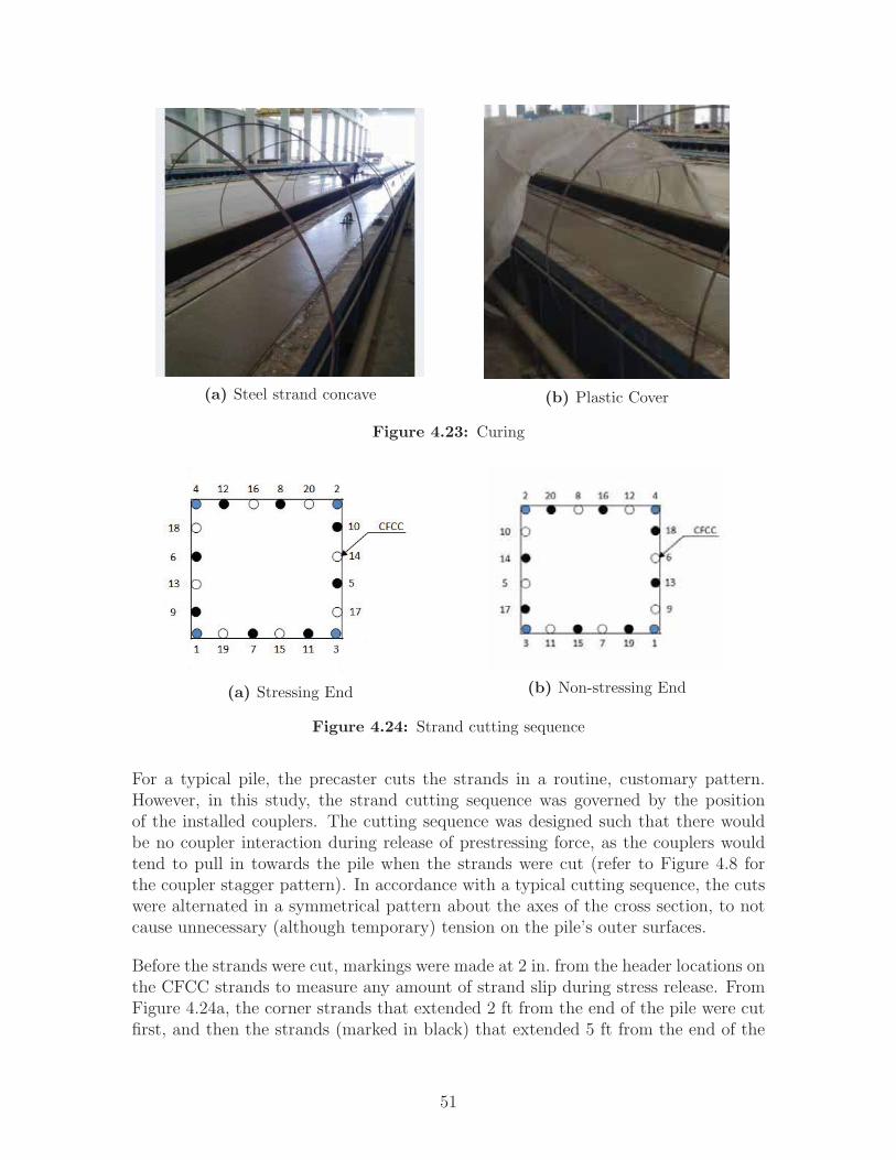
(a) Steel strand concave (b) Plastic Cover
Figure 4.23: Curing
(a) Stressing End (b) Non-stressing End
Figure 4.24: Strand cutting sequence
For a typical pile, the precaster cuts the strands in a routine, customary pattern.However, in this study, the strand cutting sequence was governed by the positionof the installed couplers. The cutting sequence was designed such that there wouldbe no coupler interaction during release of prestressing force, as the couplers wouldtend to pull in towards the pile when the strands were cut (refer to Figure 4.8 forthe coupler stagger pattern). In accordance with a typical cutting sequence, the cutswere alternated in a symmetrical pattern about the axes of the cross section, to notcause unnecessary (although temporary) tension on the pile’s outer surfaces.
Before the strands were cut, markings were made at 2 in. from the header locations onthe CFCC strands to measure any amount of strand slip during stress release. FromFigure 4.24a, the corner strands that extended 2 ft from the end of the pile were cutfirst, and then the strands (marked in black) that extended 5 ft from the end of the
51

(a) Torching the steel(b) Cutting the CFCC
Figure 4.25: Different strand cut method
pile were cut, followed by the strands (marked in white) that extended 8 ft.
Conventionally, torches were used to cut the steel strands at both the stressing andnon-stressing ends simultaneously (Figure 4.25a). After the 20 strands had been cutat each end, the CFCC strands between the pile headers were cut using a side grinder(Figure 4.25b), because CFCCs are bonded with epoxy and it is recommended to nottorch them. The distance in the headers between the pile ends was only about 1 ft,but this distance could be increased so that the operator cutting the strands will havea greater space in which to lower the grinder for cutting the strands at the bottom.
The EDCs monitored concrete strains, during stress release, in the two (2) 100–ftpiles. Similarly, electrical strain gages were used to monitor the concrete strains inthe three (3) 40–ft piles. The experimental program and instrumentation setup areexplained in the next chapter.
52

CHAPTER 5
EXPERIMENTAL PROGRAM
5.1 Transfer Length Tests
5.1.1 Introduction
As mentioned in Chapter 2, the transfer length is the distance from the end of theprestressing strand to the point where the effective stress in the strand is developed.In a pretensioned member, this stress is transferred from the strand to the surroundingconcrete through bond. The length over which the stress is transferred is inverselyproportional to the bond strength. For design, it is necessary to predict this length,so that it is known where the effective prestress has been fully transferred to themember’s cross section.
This section describes the experimental program designed to measure the CFCC’stransfer length in this study. Monitoring the piles was done at Gate Precast Companyon July 26, 2013, while the piles were in their casting bed. Concrete strains werecontinuously monitored at the ends of the piles while the steel strands were beingtorch cut and while the CFCC strands were being cut with a side grinder. This datashows the gradual transfer of prestress to the surrounding concrete throughout thestrand cutting operations.
5.1.2 Test Setup and Instrumentation
The three (3) 40–ft piles were equipped with electrical resistance strain gages on thetops of the piles, so that concrete strains could be measured during stress release.The strain gage application was started after the concrete was allowed to cure for 24hours. The strain gages had an effective length of 60 mm (2.36 in.) and were installedat the ends of the piles and at mid span.
53

On all three (3) pile specimens, the strain gage locations were kept similar, as shown inFigure 5.1. One end of the pile was instrumented with eight (8) strain gages along thecenterline of the pile, and the other end had 18 strain gages installed approximatelyalong the top corner strands.
Figure 5.1: Strain gage layout on top of pile for transfer length test(Not to scale)
Strain gage application was done as follows:
1. The concrete at the strain gage locations was smoothed with a grinder.
2. The smooth surface was cleared of dust by spraying it with acetone and wipingit clean.
3. Centerline location markings were made on the smoothened surface.
4. Strain gages were applied using Zap gel glue.
5. The strain gage lead wires were secured by taping them to the concrete withduct tape.
The strain gages on a given pile were connected to a channel which in turn wasconnected to the data acquisition system located adjacent to the center of the three(3) 40–ft piles. The system was provided and controlled by FDOT. The strain gageswere checked for weak bond with the concrete by looking for violent jumps in thestrain readings, and gages with irregular readings were replaced. The strain gageswere numbered as shown in Figure 5.2, starting from the stressing end of the bed. Forexample, for strain gage number S103, S represents a strain gage, and 103 representsthe first pile and the third strain gage on the pile. Similarly, the gage numberson the second and third piles started with S201 and S301, respectively. After theinstallation was complete, the concrete strains were monitored throughout the stressrelease process. The results are discussed in Chapter 6.
54

Figure 5.2: Strain gage numbering for transfer length test (Top view ofpile in casting bed)
The two (2) 100–ft piles were instrumented with Embedded Data Collectors, as pre-viously discussed. As shown in Figures 5.3 and 5.4, the data collector steel frameswere placed at a distance of two (2) pile widths from the head of the pile and one (1)pile width from the bottom of the pile.
Figure 5.3: Typical EDC layout (FDOT)
Figure 5.4: EDC installation
55

After the concrete was cast, the strains were recorded through a wireless receiver;this continued throughout the strand cutting operations. EDC installation and datamonitoring was done by Applied Foundation Testing, Inc. The results from the EDCmonitoring are discussed in Chapter 6. The EDCs were also used to monitor the two(2) 100–ft piles during driving.
5.2 Development Length and Flexure Tests
5.2.1 Introduction
For design, it is necessary to predict the length required to develop the strand’sultimate strength. This development length is the length at which the failure modechanges from bond slippage failure to rupture of the tendons. The design of pilefoundations also requires calculation of the pile’s flexural capacity.
This section explains the experimental setup, instrumentation layout, and test pro-cedures used for development length and flexure tests in this study. The shear spanlength was varied to determine the development length of the CFCC strands. Anadditional test was performed to determine the flexural capacity of the pile. The twodevelopment length tests were performed on September 6 and 10, 2013. The flexuretest was performed on September 12, 2013.
5.2.2 Test Matrix and Setup
Two (2) of the 40–ft piles were used for experimentation purpose at the FDOT Struc-tures Research Center in Tallahassee, Florida, 45 days after casting. (The third 40–ftpile that had been cast was kept for possible future testing.) The piles were placed ina test setup, similar to the one presented by Gross and Burns (1995). For each testsetup, the pile was simply supported. Two (2) development length tests were per-formed on the first pile, which had a cantilevered end (Figure 5.5a). One (1) flexuretest was performed on the second pile, with supports on the ends (Figure 5.5b).
The piles were supported by two (2) steel I–beams. The I–beams were leveled andgrouted to the lab’s concrete floor with quick-setting anchoring cement. Depending onthe span length of the simply–supported section of the pile, the supports were movedinto position, and hence the supports were grouted two (2) times for the three (3) testsperformed. The curing time for the grout was about 4 hours. Elastomeric bearingpads were placed between the supports and the pile. The height of the support gavethe piles about a 2-ft clearance above the testing floor.
A point load was applied to the pile by an Enerpac actuator. As the predicted
56

(a) Test setup for development length tests
(b) Test setup for flexure test
Figure 5.5: Test setups
development length was less than 10 ft, the point load was applied close to the supportfor the development length tests on the first pile. This load arrangement, along withthe cantilever length at the other end, “preserved” the other pile end for an additionaltest. Load was measured with a load cell and was initially applied on the pile specimenat a rate of 250 lb per second. An elastomeric pad was used under a steel loadingplate with a groove that fit the tip of the actuator, as seen in Figure 5.6.
Parameters that were varied for each test are as follows:
1. Length of the simply–supported span (S.S. Span)
2. Length of the cantilever overhang
3. Length of the shear span
4. Embedment length of the strand
Test parameters are summarized in Table 5.1. For the development length tests,parameters were chosen to ensure the structural integrity of the cantilever end of thebeam, so that two (2) experiments could be performed on one (1) pile specimen. TestP-6–22 Dev, for example, indicates a pile specimen tested for development length ofstrands, having an embedment length of 6 ft and a cantilever length of 17 ft. Afterthe first test was completed, approximately 6.5 ft of the pile’s tested/damaged end
57

Figure 5.6: Loading setup
was separated from the specimen and discarded. The remaining 33.5–ft length wasused for the second test. The damaged end was cantilevered approximately 5.5 ft (seeFigure 5.5a), and the undamaged, opposite end of the pile was loaded.
Table 5.1: Test matrix
Test Test Pile Simple-Supp. Shear Cantilever EmbedmentNo. Designation No. Span Span Length Length
ft ft ft ft1 P-6–22 Dev 1 22 5 17 62 P-10–27 Dev 1 27 9 5.5 103 P-38 Flex 2 38 13.3 N.A. 14.3
5.2.3 Instrumentation for the Development Length Tests
Instrumentation for each development length test was planned to monitor the follow-ing:
1. Applied load
2. Vertical deflections at several points
3. Concrete top fiber strains around the load point
58

4. Strand end slip
The instrumentation layout for the first development length test is shown in Fig-ure 5.7. Six (6) deflection gages were mounted along the length of the pile to monitorvertical deflections. The two (2) adjacent deflection gages placed at the load pointlocation were averaged in the data analysis. Four (4) electrical resistance straingages were installed to monitor the top fiber strains in the concrete around the loadpoint (Figure 5.7). Strand end slip measurements were made during testing usinglinear variable displacement transducers (LVDTs). The devices were anchored withclamps to four CFCCs in the bottom of the pile (Figure 5.8). Strand slips, monitoredthroughout the tests, reflected the displacement of the strand relative to the beam.The test setup is shown in Figure 5.9.
Figure 5.7: Gage layout for first development length test (Plan view)(Not to scale)
Figure 5.8: Strand slip measurement device
59

Figure 5.9: A pile being tested for development length
5.2.4 Instrumentation for Flexure Test
The flexure test used instruments to measure the following:
1. Applied load
2. Vertical deflections at several points
3. Concrete top fiber strains in the constant–moment region
4. Strand end slip
Fourteen (14) strain gages and ten (10) non–contact deflection gages were installedon the specimen, as shown in Figure 5.10.
Two (2) strain gages were located on the concrete surface at mid span (under theactuator location) to measure the top fiber compressive strain. Two (2) other straingages were placed at 8 in. from the center. Angles were anchored to the side face bydrilling holes in the concrete, and then the lasers from the displacement gages wereprojected on to the angle face (Figure 5.11) to measure the displacement. In additionto these gages, four (4) strand slip gages were installed to measure any strand slipduring flexure (Figure 5.8). A single point load was transferred to a spreader beam,which was formed of two (2) steel I-beams. The spreader beam supports caused two(2) point loads to be applied to the pile and thereby a constant-moment region inapproximately the middle third of the pile. The weight of the spreader beam and itsbearing plates was approximately 3000 lb. The setup is shown in Figure 5.12.
60

(a) Plan view
(b) Elevation view – east face
(c) Elevation view – west face
Figure 5.10: Gage layout for flexure test (Not to scale)
Figure 5.11: Laser device setup for measuring displacement
61

Figure 5.12: Test setup for flexural test
5.2.5 Test Procedure for Development Length and FlexureTests
For safety purposes, wooden logs were placed under the load point, where the max-imum deflection was expected. Load was then applied at a rate of 250 pounds persecond until the formation of the first flexural cracks. After that, the rate was changedto 200 pounds per second. The test continued until a bond or flexural failure occurred.A substantial loss in the member’s load capacity would be the result of a bond fail-ure, which would be accompanied by strand slippage of one or more strands. Flexurefailure is evidenced by vertical cracks in the bottom of the pile and extending upwardas the load is increased. When failure was achieved, the pile was unloaded. Crackpropagations on the concrete surface were marked after the failure, and a detailedcrack pattern was then sketched. A similar procedure was followed for the secondtest on the first pile, and again for the third test, varying the parameters given inTable 5.1. The results from the tests are discussed in Chapter 6.
62

5.3 Pile Driving Test Setup
The two (2) 100–ft piles were stored at GATE until a suitable bridge constructionproject on which to drive them was found. In late January 2014, the piles were de-livered to Deer Crossing Bridge (Bridge No. 790207) being constructed on Interstate4 near milepost 127, west of U.S. Highway 92. This is located in Volusia County be-tween Daytona and Deland. The piles were installed by the contractor, The de MoyaGroup, Inc., on January 23 and 24, 2014. They were driven adjacent to productionpiles on End Bent 3-1 located at Station 1177+48.0 on the westbound bridge. Thepiles were installed on the west end of the bent, near Boring DC-1. See Appendix Efor a plan view of the bridge and soil boring logs. See Appendix H for photos of thesite and pile driving activities.
The purpose of these pile driving tests was to “test the limits” of the piles. The firstpile was driven as a normal pile would be, as determined by FDOT personnel on site,and was then subjected to hard driving during the latter part of installation. Thesecond pile was installed under hard driving conditions to test the limits more andto test for repeatable behavior. Both piles were driven to refusal. After testing, thepile tops were to be cut off to 2 ft below grade, and the piles were to be covered bysoil and abandoned in place.
Both EDC and PDA were used to monitor the stresses in the piles while they werebeing driven. During the installation of piles, high impact forces imposed by the piledriver hammer occur. The hammer blow causes a compression wave that travels atabout the speed of sound. When it reaches the pile tip, it reflects. Depending onthe soil resistance, the reflecting wave can cause compressive or tensile stresses in thepile. This wave can cause damage to the concrete, high stresses in the prestressingstrands, and possible rupturing of the bond between the steel and concrete.
Additional details regarding the tests (for example, the pile driving hammer andcushion details) are provided in a test summary report prepared by FDOT (see Ap-pendix E).
63

CHAPTER 6
EXPERIMENTAL TEST RESULTS
6.1 Introduction
One purpose of this experimental program was to determine the transfer length ofCFCC strands by way of measuring concrete strains at the ends of the piles while thestrands were being detensioned in the casting bed. Another purpose was to determinethe development length of the CFCC strands, in addition to determining the flexuralstrength of the pile. Lastly, the purpose was to test the behavior of the pile while itwas being driven into the ground as part of a bridge foundation. This chapter reportsthe results that were obtained from all of these tests.
6.2 Transfer Length Measurements
6.2.1 General
The concrete strength at 24 hours after casting was 5370 psi. This is an average oftwo (2) cylinder strengths, 5320 and 5420 psi, as determined by GATE. As explainedin Section 5.1, three (3) 40–ft prestressed concrete piles were monitored during releaseof prestressing. Both ends of each pile were instrumented with strain gages and weredesignated as follows: 3N, 3S, 4N, 4S, 5N, and 5S, where the numbers 3 through 5represent the pile number as per the bed layout shown in Figure 4.5. ’N’ representsthe North end, which was the stressing end of the bed, and ’S’ represents the Southend, which was the non–stressing end. The strain gage layout is shown in Figure 5.1,and a photo of the strain gages near the stressing end is in Figure 6.1.
64

Figure 6.1: Strain gage layout at stressing end
6.2.2 Measured Strains at Transfer
Figure 6.2 shows the strain profile along the length of pile ’3’, with each line represent-ing the strains after a strand was cut. This demonstrates the increasing compressivestress on the pile as the force in each strand was released. The strain profiles for allsix (6) pile ends after 75% and 100% release are shown in Figures 6.3 through 6.14.Here, 75% release refers to 15 strands being released, and 100% release refers to allstrands being released. In these figures, the strain is shown from the pile end to themid span. The strains reported in Figures 6.2–6.4, 6.7–6.8, and 6.11–6.12 for thestressing ends are average readings of pairs of strain gages located at the top cornersof the pile specimen. For example, the plotted strain at 3 in. from the pile end is theaverage of the strains in strain gages S101 and S102 (Figure 5.2).
There are two commonly–used methods to measure the transfer length of a strand:(1) the 95% Average Maximum Strain (AMS) method (Russell and Burns, 1996)which uses the measured strains along the transfer zone of a prestressed member and(2) the “draw–in” or “end–slip” method. The AMS method was used in this study.The idealized theoretical strain profile as explained by Mahmoud and Rizkalla (1996)would show a linear increase in strain in the transfer zone, followed by a uniform strainplateau. However, for the pile end ‘4N’, the data shows a linear increase in strain inthe transfer zone, but a uniform strain plateau was difficult to define. Therefore, forthis pile end, the transfer length was estimated by a visual analysis.
For all other pile ends, the 95% AMS method was used to determine the transferlength of CFCC. The procedure as explained by Russell and Burns (1996) is as follows:
1. Strains after the prestress release are recorded and used to determine the strainprofile within the transfer zone.
2. Data may be smoothed if required, by taking the strain at any point ’b’ as theaverage of the strains at three adjacent points centered at ’b’.
65

3. The strain plateau region, or the distance over which strain is at a nearly con-stant maximum, is estimated visually. The average strain within the plateau iscalculated. A line corresponding to 95% of this average strain is superimposedon the strain profile.
4. The intersection of the 95% AMS and the strain profile defines the transferlength.
The transfer lengths determined from the AMS method for the 75% and 100% stressrelease measurements were averaged. These average transfer lengths for each pile endare given in Table 6.1.
Figure 6.2: Strain profile for pile 3 at release
Figure 6.3: Strain profile for pile end 3N at 75% stress release
66

Figure 6.4: Strain profile for pile end 3N at 100% stress release
Figure 6.5: Strain profile for pile end 3S at 75% stress release
Figure 6.6: Strain profile for pile end 3S at 100% stress release
67

Figure 6.7: Strain profile for pile end 4N at 75% stress release
Figure 6.8: Strain profile for pile end 4N at 100% stress release
Figure 6.9: Strain profile for pile end 4S at 75% stress release
68

Figure 6.10: Strain profile for pile end 4S at 100% stress release
Figure 6.11: Strain profile for pile end 5N at 75% stress release
Figure 6.12: Strain profile for pile end 5N at 100% stress release
69

Figure 6.13: Strain profile for pile end 5S at 75% stress release
Figure 6.14: Strain profile for pile end 5S at 100% stress release
Table 6.1: Transfer length for specimen pile ends
Pile End Transfer Length (in.)
3N 29.03S 21.54N 25.54S 22.05N 28.05S 24.5
Average Transfer Length 25.0
70

6.3 Development Length Test Results
Two (2) development length tests on one (1) 40–ft pile specimen were conducted.The test results are presented in this section, including load versus deflection plots,as well as sketches of cracking patterns that occurred.
6.3.1 Test 1
The pile specimen was prepared for testing as explained in Chapter 4. For the firsttest, the embedment length was 6 ft, the simply–supported span length was 22 ft, andthe cantilever length was 17 ft. The plot of applied load versus deflection, calculatedfrom the average of deflection gages D3 and D4 adjacent to the applied load, is shownin Figure 6.15. The first flexural crack was observed at a load of 175 kips and extendedup to 2 ft from the load point to the free end of the pile. The flexural cracks hadpropagated to 4 in. from the top fiber. The load was applied until failure occurred at205 kips. The final crack pattern is shown in Figures 6.16 and 6.17. The maximumtop fiber strain in the vicinity of the load point at failure was 0.0012. The appliedload versus the average strain in the four (4) gages around the load point (Figure 5.7)is shown in Figure 6.18. During loading, one of the strain gages next to the loadpoint location gave erroneous data at 40 kips, but after 43 kips, both the strain gagesgave similar readings. There was no observable strand end slip on any of the four (4)instrumented CFCC strands throughout the test.
71

Figure 6.15: Load vs. Deflection for Test 1
Figure 6.16: Failure crack pattern on east face for Test 1
72

Figure 6.17: Failure crack pattern on west face for Test 1
Figure 6.18: Load vs. Strain for Test 1
73

6.3.2 Test 2
The pile specimen from Test 1 was used again for Test 2. The structural integrity ofthe cantilevered end from the Test 1 setup remained undisturbed throughout Test 1,so this pile end (opposite the tested end from Test 1) was used to perform Test 2. Forthis second test, the embedment length was 10 ft, the simply–supported span lengthwas 27 ft, and the cantilever length was approximately 5.5 ft. The loading procedurewas similar to Test 1, as were the strain gage and deflection gage layouts. A plot ofapplied load versus deflection, calculated from the average of deflection gages D3 andD4 adjacent to the applied load, is shown in Figure 6.19.
Figure 6.19: Load vs. Deflection for Test 2
The first flexural crack occurred at a load of 101 kips, on the bottom of the pileunder the load application point. The cracks propagated up to 3 in. from the topfiber and extended up to 3 ft from the load point towards the free end of the pile.The test resulted in a flexural failure at a load of 120 kips and a deflection of 2.8 in.The maximum strain in the top fiber in the vicinity of the load point at failure was0.00138. Local concrete crushing occurred on the top of the pile near the load pointat failure (Figure 6.20). Sketches of the crack patterns on the east and west faces areshown in Figures 6.21 and 6.22. There was no observable strand slip in any of thefour (4) instrumented CFCC strands throughout the test.
74

Figure 6.20: Concrete crushing at top in Test 2
Figure 6.21: Failure crack pattern on east face for Test 2
75

Figure 6.22: Failure crack pattern on west face for Test 2
6.4 Flexural Strength Test Results
Three (3) 4–in. x 8–in. concrete cylinders were tested on the day of the flexuralstrength test and had an average compressive strength of 9500 psi. The applied loadversus deflection is plotted in Figure 6.23, where the plotted deflections are averagesof gages D5 and D6 at mid span. Failure occurred at a load of 113 kips and a mid-span deflection of 9.63 in. (Figure 6.23). This does not include the effects due to theself weight of the pile or the spreader beam weight. The maximum concrete strainrecorded was 1300 microstrains, from strain gages S3 and S4 at mid span. There wasno strand end slip observed in any of the four (4) instrumented strands throughoutthe test. Sketches of the crack pattern on the east and west faces are shown in Figures6.24 and 6.25. The cracks were uniformly distributed in the constant-moment regionand extended up to 5 ft from the load points toward the ends of the pile. At themaximum load, the flexural cracks propagated to about 3 in. from the top fiber.Failure of the pile occurred under one of the load transfer points on the spreaderbeam shown in Figure 6.26.
As previously stated, the pile specimen failed at an applied load of 113 kips, whichequates to a calculated moment of 753 kip–ft. This generated a total calculated testmoment of 875 kip–ft, including an initial calculated moment of 122 kip–ft due tothe self weight of the pile and the spreader beam weight of approximately 3000 lb.The theoretical pile capacity was calculated to be 809 kip–ft (see Appendix F), for atest–to–theoretical moment ratio of 1.08 (Table 6.2).
The results obtained from the transfer length, development length and flexural testsare discussed in Chapter 7.
76
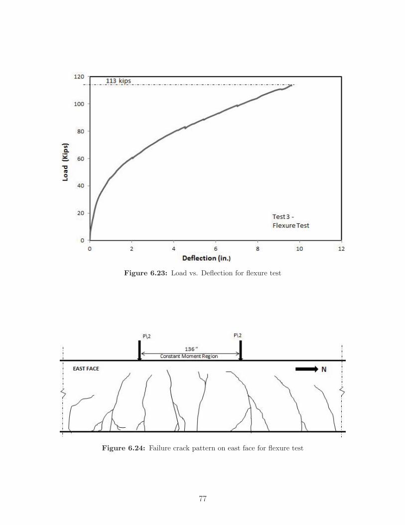
Figure 6.23: Load vs. Deflection for flexure test
Figure 6.24: Failure crack pattern on east face for flexure test
77

Figure 6.25: Failure crack pattern on west face for flexure test
Figure 6.26: Failure under one of the load points
78

Table 6.2: Theoretical vs. test moment capacity
Moment Capacity (kip–ft)Theoretical 809
Test 875Ratio (Test/Theoretical) 1.08
6.5 Pile Driving Test Results
6.5.1 Introduction
Both EDC and PDA were used to monitor the piles during driving. FDOT also pro-vided geotechnical expertise and assessed the performance of the pile through obser-vations and EDC and PDA test results. Data and reports are included in Appendix E,and selected photos are in Appendix H. With the researchers, representatives fromFDOT Structures Research Center and FDOT Central Office were on site duringdriving of the first pile on January 23, 2014. For the second pile, driven on January24, FDOT representatives were not able to attend.
The piles were designed to have a permanent compression of 1000 psi at the effectiveprestress level, after losses. The piles were subjected to 2765 and 3139 hammer blowsfor Piles 1 and 2, respectively. See Chapter 7 for a discussion of the test results.
Two (2) 4-in. x 8-in. cylinders were tested at the FDOT Structures Research Centeron January 28, 2014. The compressive strengths were 9,849 and 10,313 psi, for anaverage of 10,080 psi.
6.5.2 Embedded Data Collectors (EDC) Results
EDC data was gathered and reported by Applied Foundation Testing, Inc. (AFT).The Embedded Data Collector was unable to connect to the second pile, so data wascollected only for the first pile driven on January 23. EDC results and the reportprepared by AFT are provided in Appendix E.
6.5.3 Pile Driving Analyzer® (PDA) Results
PDA data was gathered for both piles and reported by GRL Engineers, Inc. GRL’sreport on the results, including the pile driving logs kept by the field inspector, is
79

provided in Appendix E.
6.5.4 FDOT Summary Report
FDOT’s Assistant State Geotechnical Engineer, Rodrigo Herrera, P.E., evaluated thetest results and prepared a summary report on the pile driving activities and pileperformance. The report is in Appendix E. It provides a chronicle of the drivingoperations, including details about the pile cushions that were used and when theywere replaced. The report also notes cracking that was observed and comments onthe pile integrity.
Herrera calculated maximum stress limits and compared them to the stresses to whichthe piles were subjected. Although driving and subsurface conditions prevented thedevelopment of maximum compression stresses of 6.25 ksi, per FDOT Specification455-5.11.2 (FDOT, 2014a) and based on measured concrete compressive strength,the stresses in the piles did exceed the typical limit used in production pile driving(which is 3.6 ksi, assuming a nominal 6000 psi concrete strength and 1000 psi forinitial prestress). In addition, the theoretical limit on tension stress, 1.38 ksi basedon measured concrete compressive strength, was exceeded during driving.
The pile heads were locally damaged; the concrete spalled, likely due to the intentionaluse of thin cushions and hard driving. Other than to the pile heads, there was nomajor pile damage. As noted by Herrera, the piles’ resistances were well beyondthe 900-kip suggested driving resistance per FDOT’s Structures Design Guidelines(FDOT, 2014b).
80

CHAPTER 7
DISCUSSION
7.1 Introduction
The results obtained from the experimental program were reported in Chapter 6.In this chapter, the findings will be discussed. Also, the challenges associated withprecasting CFCC–prestressed piles, as well as the differences between using CFCCand steel prestressing, will be explained.
7.2 Transfer Length of CFCC
The strain gage data taken during prestress release was analyzed using the 95% AMSmethod for five (5) pile ends out of six (6). The end ’4N’ did not show a distinct strainplateau and hence the strain profile was evaluated visually for the transfer length.The strain profiles for all six (6) transfer length locations are presented in Figures 6.3through 6.14, and the values of the transfer lengths are shown in Table 6.1.
The transfer length values are consistently lower than Equation 7.1 recommended byACI 440.4R–04.
Lt =fpidb
αtf ′ci0.67 (7.1)
The factor αt was determined by Grace (2000) to be 11.2 (for psi and in. units) or 2.12(for MPa and mm units); this results in a predicted transfer length of 37.3 in. fromEquation 7.1 for fpi of 220 ksi. The observed transfer length was 25 in., which is 33%lower than predicted. Mahmoud et al. (1999) proposed for αt a value of 25.3 (forpsi and in. units) or 4.8 (for MPa and mm units) to predict the transfer length of aCFCC tendon. This results in a predicted transfer length of 16.5 in., which is 34%lower than observed.
81

From Table 6.1, the transfer lengths at the stressing ends, denoted by ’N’, are higherthan the transfer lengths at the non–stressing ends, denoted by ’S’. The averageratios of non–stressing to stressing end transfer lengths ranged from 0.74 for pile ‘3’to 0.86 for piles ‘4’ and ‘5’. According to Pozolo (2010), transfer lengths might beinfluenced by factors such as concrete casting location, cutting location, and the useof multiple batches of concrete. However, the strain gage locations (offsets from thepile’s longitudinal axis) were different for the non–stressing ends than for the stressingends, which could explain the different transfer length results.
Furthermore, the transfer length observed in this study was 31% less than the AASHTOprovision of 60db (36 in.). In ACI 318-11, the transfer length of a prestressing strandis as follows:
Lt =fsedb3
(7.2)
This results in a predicted transfer length of 40.2 in., using an effective prestress fse of201 ksi after all prestress losses, as calculated per PCI (2010). Note that the equationdoes not account for the concrete compressive strength at the time of release. Theobserved transfer length was 38% less than that predicted by Equation 7.2.
7.3 Development Length Tests
A crack is termed as “flexural” if it originates as a vertical crack that propagatesupwards from the bottom surface. Tests 1 and 2, performed on the two (2) ends ofone (1) 40–ft pile, failed in flexure. The shortest embedment length used in these two(2) test setups was 72 in. Development length is the shortest embedment length thatdevelops the strand’s flexural capacity without any bond slip, so these tests indicatethat the strand was developed in less than 72 in.
Table 7.1 provides development length predictions per equations from ACI (2011),AASHTO (2011), Mahmoud and Rizkalla (1996), and Lu et al. (2000). The equationby Lu et al. (2000) for predicting development length is as follows:
Ld =1
3fsedb +
3
4(fpu − fse)db (7.3)
Equation 7.3 results in a predicted development length of 102 in., which is 42% higherthan the shortest embedment length tested in this study.
See Chapter 2 for the equations by others.
The predicted development length according to ACI and AASHTO is 123 in., whichis 71% higher than the shortest embedment length tested. The low value of the
82

Table 7.1: Development length predictions
Predicted Length (in.)Lu et al. (2000) 102
ACI 318-11 and AASHTO LRFD 123Mahmoud and Rizkalla (1996) 29
Mahmoud and Rizkalla (1996) with Grace (2000) αt 49
development length might be due to the characteristic properties of CFCC and alsomight be a result of using high–strength, self–consolidating concrete. For a moreaccurate prediction of the development length, more testing would be needed.
7.4 Flexural Strength Tests
Table 6.2 shows that the flexural strength of the concrete pile prestressed with CFCCis 8% higher than the theoretically-predicted strength. Furthermore, the mid spandeflection at failure was 9.26 in., which indicates high ductility. In research conductedby Abalo et al. (2010), tests were performed on a 24–in. diameter circular concrete pile,prestressed with 20 0.5–in. diameter strands which were wrapped with a CFRP meshin lieu of spiral ties. The performance of this specimen was compared to a controlpile, a 24–in. square prestressed concrete pile prestressed with 16 0.6–in. diametersteel strands. The results of the tests on the control pile can be compared to the24–in. square pile tested in the current study, although a direct comparison shouldnot be made. The pile in the current study contained 20 0.6–in. diameter CFCCstrands instead of 16 steel strands, and the strand layout and stressing forces weredifferent. Table 7.2 compares the flexure test results on the control pile from Abaloet al. (2010) to the results of the CFCC pile test in this study.
Table 7.2: Moment capacity comparison
Moment Abalo et al. (2010) CFCC-PrestressedCapacity Control Pile Pile Specimen
kip-ft kip-ftTheoretical 625 809
Test 759 875Ratio (Test/Theoretical) 1.21 1.08
The CFCC-prestressed pile capacity was greater than the theoretical capacity andgreater than the control pile from Abalo et al. (2010). There was no strand end
83

slip throughout the tests, which demonstrates that the CFCC has a good bond withconcrete.
7.5 Pile Driving Tests
Both piles performed well during installation at the Interstate 4 bridge constructionsite, even though they were subjected to hard driving conditions and high levels ofstress. There was no major damage to the piles, other than concrete spalling at thepile heads, which was likely due to the intentional use of thin driving cushions.
Pile capacities calculated by PDA were approximately twice the value of FDOT’ssuggested driving resistance for a conventional 24-in. prestressed pile. The data alsosuggests that there was no significant loss of prestress.
7.6 Lessons Learned from First Attempt to Pre-
stress
Before September 2012, plans were made to precast five (5) concrete piles prestressedwith 20 0.5–in. diameter CFCC strands. The casting setup and layout were similar tothat described in Chapter 4. On September 10-12, 2012, the first attempt was madeto cast the piles using 0.5–in. diameter strands. The only difference between the pilesthat were attempted in September 2012 and the piles that were successfully cast inSummer 2013, about which the results in this report are based, is that 0.5–in. diameterstrands were used instead of 0.6–in. diameter strands. The coupler dimensions alsodiffered because of the different strand diameters.
In the first attempt, after the CFCC strands, spirals, and couplers were installed inthe precasting bed, the stressing operations began. Initially, all strands were partiallystressed in the sequence shown in Figure 7.1. Thereafter, full stressing to 29 k began.While the third strand was about to be fully stressed, the first CFCC strand thathad been fully stressed slipped from the coupling device. All prestressing operationswere stopped.
The researchers summarized the efforts in a short presentation, which is included inAppendix G.
84

Figure 7.1: Stressing sequence for first casting attempt
The CFCC coupling device from which the strand had slipped was locally investigatedby the researchers, CFCC manufacturer, and precasting personnel at GATE, andpossible reasons for the slippage were speculated as follows:
1. Hoyer EffectDuring the prestressing operation, the strand might have reduced in diameter,thus reducing the frictional forces between the wrapping mechanism and thecoupler sleeve.
2. Length of the wedgesThe length of the wedges gripping the CFCC strand after the seating wasachieved might not have been adequate.
3. Twisting of the CFCC strandsIt was observed that the strand had twisted during the stressing operation. Thismight have resulted in loss of contact between the wrapping material and theCFCC strand.
The CFCC manufacturer, Tokyo Rope, took several couplers (with short extensionsof strands attached) to Japan and performed an investigation of the failed coupler aswell as other couplers that had been installed. They concluded that the molybdenumlube spray that was used was not able to seat the wedges completely due to lack oflubrication and hence the seated length of the wedges was inadequate to generate
85

the frictional forces required to grip the CFCC strand. To remedy this at the nextattempt, in Summer 2013, Tokyo Rope provided their own special molybdenum spray.
Tokyo Rope also noted that the seating of the wedges was not consistent from cou-pler to coupler. To remedy this, they developed the coupler installation proceduredescribed in Chapter 4 and Appendix A. The main differences between the previousinstallation procedure (which was used for prestressing the 0.5–in. diameter strandsin Summer 2012) and the new technique used in Summer 2013 are given below:
1. The Mesh Sheet Wrapping
The earlier technique of wrapping the mesh sheet to the strand employed two (2)separate mesh sheets (Figure 7.2a). This may not provide complete wrappingon the CFCC strand. The new technique (Figure 7.2b) involved wrapping theCFCC strand uniformly with a continuous mesh sheet and provides a betterand more uniform grip on the strand.
(a) Earlier Technique (2012)
(b) New Technique (2013)
Figure 7.2: Mesh sheet installation technique
2. Wedge Installation
In the new technique, the wedges were marked at 55 mm from the larger end ofthe wedges. A pneumatic jack was used to install the wedges into the sleeve. Theprevious method was to hammer the wedges into the sleeve. The new methodprovided a uniform and consistent installation of the wedges (Figure 7.3).
The new techniques used to install the couplers were successful in prestressing thestrands and are now a standard used by Tokyo Rope.
86

(a) Earlier Technique (2012)
(b) New Technique (2013)
Figure 7.3: Wedge installation method
87

CHAPTER 8
SUMMARY AND CONCLUSIONS
8.1 Summary
This study investigated the following: installation procedures for CFCC strandsand stressing couplers; CFCC bond characteristics (transfer length and developmentlength); and the flexural capacity of a pile that is prestressed with CFCC strands.In addition, the behavior of a CFCC-prestressed pile during driving operations wasobserved and analyzed.
To meet the research objectives, piles were cast and several tests were performed.The research activities and tests were as follows:
1. Five (5) 24–in. square prestressed concrete piles were cast using 20 0.6–in. diam-eter CFCC prestressing strands, manufactured by Tokyo Rope ManufacturingCompany. Produced at Gate Precast Company in Jacksonville, Florida, thesefive (5) piles included two (2) 100–ft and three (3) 40–ft specimens.
2. Transfer length tests were performed at GATE on the three (3) 40–ft piles.
3. Two (2) development length tests were performed on one (1) of the 40–ft pilesat the FDOT Marcus H. Ansley Structures Research Center in Tallahassee,Florida.
4. One (1) of the 40–ft piles was tested for flexural strength at the FDOT MarcusH. Ansley Structures Research Center. The third 40–ft pile is stored at thelaboratory for future studies, if needed.
5. The two (2) 100–ft piles were driven at an Interstate 4 bridge construction sitein Volusia County, Florida, to monitor the static resistance of the piles and thepile behavior during driving.
88

8.2 Conclusions
8.2.1 Transfer Length of CFCC
An analysis of the transfer length tests, particularly of the data obtained from theelectrical resistance strain gages, suggests that the CFCC strands have a 25–in. trans-fer length, which is 38% and 31% less than that predicted by ACI and AASHTO,respectively, for steel strands. The observed transfer length is 33% lower than thetransfer length calculated from ACI 440.4R–04 and using the alpha factor by Grace(2000). Testing of more pile specimens could be performed to determine an alpha fac-tor for CFCC strand transfer length predictions. Nonetheless, the observed transferlength is conservative, in that it is less than the predicted values.
The strain variation at the pile ends shows that the transfer lengths observed at thestressing ends were higher than those at the non–stressing ends. This could be dueto the differing strain gage layouts at the ends: pairs of gages were placed near thecorners at the stressing ends, whereas a single line of gages was placed along the pilecenterline at the non–stressing ends.
8.2.2 Development Length of CFCC
The Test 1 pile had an embedment length of 72 in. Because the pile failed in flexure,rather than by failure of the strand–to–concrete bond, the development length couldnot be determined in this study. However, it can be concluded that the developmentlength of CFCC is less than 72 in. and therefore also less than the AASHTO predictionof 123 in. for steel strands and with CFCC’s value for GUTS.
8.2.3 Flexural Strength of CFCC–Prestressed Pile
The flexural strength of the CFCC–prestressed concrete pile was 8% higher thantheoretical. The test results suggest that the flexural performance of piles with CFCCstrands is comparable to that of piles with steel strands. The cracking pattern in allthree (3) tests (the two (2) development length tests and the flexural test) was asanticipated for a flexural failure. In all tests, there was no end slip in any of thestrands, which indicates a good bond characteristic of the CFCC with concrete. Inaddition, the pile’s mid span had deflected over 9 in. at failure, which indicates goodductility. This is consistent with the approximate 10–in. deflection of concrete pileswith similar dimensions that were prestressed with steel and tested by Abalo et al.(2010).
89

8.2.4 Pile Driving
Two (2) 100–ft piles were subjected to hard driving conditions and high internalcompressive and tensile stresses. They both performed well, with no major damageor loss of prestress.
8.2.5 Specimen Production
There are unique challenges associated with using CFCC strands in a prestressedconcrete pile. The precaster has to adapt to a new technique of stressing the strandwith respect to:
1. Coupler installation
2. Proper handling of the CFCC to prevent damage
3. Concrete consolidation during placement, preferably without a vibrator to pre-vent damage to strand
4. The stressing method of CFCC strands, with regard to a slower–than–normalstressing rate recommended by the manufacturer
5. Use of a different header material (e.g., wood instead of steel) to prevent damageto CFCC strands while installing them in the precasting bed
8.3 Suggestions for Future Research
Suggestions for future research are as follows:
1. More testing could be performed to better estimate the value of the alpha factorin the ACI 440.4R–04 equation, by varying parameters such as the diameter ofthe CFCC, the prestressing force, and the concrete strength.
2. More tests could be performed to evaluate the development length of CFCC inprestressed concrete piles. The conclusions reported herein are based on onlytwo (2) tests, for which the pile failed in flexure rather than the CFCC failingin bond.
3. Research should be conducted to further improve the anchorage system for theCFCC strands, with the goal being to make installation easier and faster forthe precaster.
90

4. Specifications need to be developed for the CFCC material, if it is to be specifiedfor use on future FDOT bridge construction projects. For example, necessaryprecautions or restrictions on the handing and storage of CFCC strands needto be specified. This includes acceptable levels of incidental damage.
5. Long–term properties should be further evaluated as part of specifications de-velopment.
6. Because the CFCC material does not corrode, it is possible that the 3–in. con-crete cover could be reduced. Testing could be done to verify this, for example,to make sure that an adequate amount of concrete surrounds the strand todevelop it. However, a reduced concrete cover would result in the need forprecasters’ standard templates to be modified.
7. In this test program, standard steel lifting loops to handle the piles were in-stalled. An alternative lifting loop, made of a non-corrosive material, could bedesigned and tested if a pile completely devoid of steel were desired.
8. Other uses of CFCC strands should be investigated, particularly for structuresthat normally utilize steel prestressing strands in harsh or marine environments.For example, using CFCC instead of steel strands in sheet piles could be bene-ficial and cost effective in the long term.
91
BIBLIOGRAPHY
AASHTO (2011). AASHTO LRFD Bridge Design Specifications, 6th Ed., 2013 In-terim Revisions. American Association of State Highway and Transportation Offi-cials, Washington, D.C.
Abalo, V., Potter, W., and Fallaha, S. (2010). “Testing precast pile with carbon fiberreinforced polymer mesh”. Research Report, Florida Department of Transporta-tion.
ACI (2004). ACI 440.4R-04 Prestressing Concrete Structures with FRP Tendons.American Concrete Institute, Farmington Hills, MI.
ACI (2011). ACI 318-11 Building Code Requirements for Reinforced Concrete. Amer-ican Concrete Institute, Detroit, Michigan.
Andrawes, B., Shin, M., and Pozolo, A. (2009). “Transfer and development length ofprestressing tendons in full-scale AASHTO prestressed concrete girders using self-consolidating concrete.” Report No. ICT-09-038, Illinois Center for Transportation.
Balazs, G. L. (1993). “Transfer lengths of prestressing strands as a function of draw-inand initial prestress.” PCI Journal, 38(2), 86–93.
Cousins, T., Johnston, D. W., and Zia, P. (1990). “Development length of epoxy-coated prestressing strand.” ACI Materials Journal, 87(4), 309–318.
Domenico, N. G. (1995). “Bond properties of CFCC prestressing strands in preten-sioned concrete beams”. Master’s thesis, University of Manitoba.
FDOT (2014a). FDOT Standard Specifications for Road and Bridge Construction.Florida Department of Transportation, Tallahassee, FL.
FDOT (2014b). Structures Design Guidelines, FDOT Structures Manual Volume 1.Florida Department of Transportation, Tallahassee, FL.
Grace, N. (2000). “Transfer length of CFRP/CFCC strands for double-t girders.”PCI Journal, 45(5), 110–126.
Grace, N. (2003). “First CFRP bridge in the USA.” Construction and TechnologyResearch Record, Michigan Department of Transportation, 97.
92

Grace, N. (2007). “5-years monitoring of first CFRP prestressed concrete 3-span high-way bridge in USA.” Proceedings of the 12th International Conference on StructuralFaults & Repair-2008, Engineering Technics Press.
Grace, N., Abdel-Sayed, G., Navarre, F. C., Bonus, R. B. N. W., and Collavino, L.(2003). “Full scale test of prestressed double-tee beams.” Concrete International,25(4), 52–58.
Grace, N., Enomoto, T., Baah, P., and Bebaway, M. (2012). “Flexural behavior ofCFRP precast prestressed concrete bulb t-beams.” ASCE Journal of Compositesfor Construction, 16(3), 225–234.
Gross, S. P. and Burns, N. H. (1995). “Transfer and development length of 15.2 mm(0.6 in.) diameter prestressing strand in high performance concrete: Results of theHoblitzell-Buckner beam tests.” Research Report FHWA/TX-97/580-2, Center forTransportation Research, Austin, Texas.
Herrera, R., Jones, L., and Lai, P. (2009). “Driven concrete pile foundation monitor-ing with Embedded Data Collector system.” Contemporary Topics in Deep Foun-dations, M. Iskander, D. F. Laefer, and M. H. Hussein, eds., Proceedings fromthe International Foundation Congress and Equipment Expo, Orlando, Florida,621–628.
Issa, M., Sen, R., and Amer, A. (1993). “Comparative study of transfer length infiber and steel pretensioned concrete members.” PCI Journal, 38(6), 52–63.
Logan, D. R. (1997). “Acceptance criteria for bond quality of strand for pretensionedprestressed concrete application.” PCI, 42.
Lu, Z., Boothby, T. E., Bakis, C. E., and Nanni, A. (2000). “Transfer and developmentlength of FRP prestressing tendons.” PCI Journal, 45, 84–95.
Mahmoud, Z. I. and Rizkalla, S. H. (1996). “Bond properties of CFRP prestress-ing reinforcement.” Proceedings of the First Middle East Workshop on StructuralComposites for Infrastructure Applications, S. El-Sheikh, ed., Egypt.
Mahmoud, Z. I., Rizkalla, S. H., and Zaghloul, E.-E. R. (1999). “Transfer and devel-opment lengths of Carbon Fiber Reinforced Polymers prestressing reinforcement.”ACI Structural Journal, 96(4), 594–602.
PCI (2010). PCI Design Handbook: Precast and Prestressed Concrete, 7th Ed. Pre-cast/Prestressed Concrete Institute, Chicago, IL.
Persson, B. (2001). “A comparison between mechanical properties of self-compactingconcrete and the corresponding properties of normal concrete.” Cement & ConcreteResearch, 193–198.
93

Pozolo, A. (2010). “Transfer and development length of steel strands in full scaleprestressed self-consolidating concrete bridge girders”. Master’s thesis, Universityof Illinois Urbana-Champaign.
Rohleder, J., Tang, B., Doe, T. A., Grace, N., and Burgess, C. J. (2008). “CarbonFiber-Reinforced Polymer strand application on cable-stayed bridge, PenobscotNarrows, Maine.” Transportation Research Record: Journal of the TransportationResearch Board, 2050(17), 169–176.
Russell, B. and Burns, N. (1996). “Measured transfer lengths of 0.5 and 0.6 in. strandsin pretensioned concrete.” PCI Journal, 41(5), 44–65.
Taerwe, L., Lambotte, H., and Miesseler, H. (1992). “Loading tests on concrete beamsprestressed with Glass Fiber Tendons.” PCI Journal, 37, 86–89.
94

Appendices
95

APPENDIX A
CFCC PRODUCT INFORMATION
96

CFCC MATERIAL PROPERTIES
97

�������������� ������������������������������ �������� �����������
������������������������ �� ������������������φ����� �
��!�� ��"�#�� ��! ��$%��&'((� ���������������� � ��!�� ��"�����"�� �����&'((� ������������������ ����!�)��!� ��$�����������*��� ��������������������� ����������)��� ���+�� ��� ,�$��,-$'.� ������������������ ��!��������� ������� � ��������������� ���� �������������� ��&� ���� ����/ �����0"���" � �����������)��"������ ����� ��12�����,2������ ������������������ �
��������,,,�!����
������� �� �����+�����*������- 3���� �� &�(� �" � ��"�"�����
4��� ���� 4��(�� ����� �"���� ������� (����� ���� (���"��5�� ��������� �����(��6 5((6 5((�6 5�&6 5�'(6 5�&'((�6
7����,φ ��, ���� 18 1, �$���������φ ��� 1��� �$ $, ���
������,��φ �,�� ���8 �9� ��� ������������φ ���� �$�, �89 �9� ������������φ ���� ����$ ��, ��� ������������φ ���� ����� 1�, �8% ���
���%���,��φ �,�� �,$�� 1�$ 9�, �1����%������φ ���� 1,9�� 9$� $,$ �1����%���8��φ �8�� 9,��, �%9 ��� �1���1���1���φ 1��� �%��� 89� ��8� �����1���9,�,φ 9,�, �%8�� ��,, ���% �9�
98
CFCC SPECIFICATION FROM TOKYOROPE / CABLE TECHNOLOGIES
99

No. CTCF13-002A
CFCC SPECIFICATION
FOR
24” SQUARE PRESTRESSED CONCRETE PILE
May 21, 2013
Cable Technologies North America, Inc. 26200 Town Center Drive, Novi, MI 48375
100

Contents
1 General 1 1.1 Scope 1.2 Specifications to be applied 1.3 Contact line 2 Quality and quantity of product 3 2.1 CFCC Strands 2.2 Anchoring devices 2.3 CFCC Ties
3 Specifications 9 3.1 CFCC Strands 3.2 Anchoring devices
3.3 CFCC Ties 4 Material 10 4.1 Carbon fiber prepregnation 4.2 Wrapping fiber 4.3 Wedges, Sleeves and Couplers 4.4 Polinet sheets and stainless steel meshes 4.5 Braid grips
5 Test and inspection 11 5.1 Items and number of samplling 5.2 Method of test and inspection
6 Packing and indication 12
7 Documents to be submitted 15
101

1
1 General
1.1 Scope
This specification covers shop fabrication, test, inspection and packing of the CFCC Strands and CFCC Ties for the 24” SQUARE PRESTRESSED CONCRETE PILE.
1.2 Specifications to be applied
The CFCC Strands and Ties shall be manufactured based upon the requirements documented by drawings and statements in the following specifications.
(1) FDOT DESIGN STANDARDS FY 2012/2013 40’-0” 24” SQUARE PRESTRESSED CONCRETE PILE (SHEET NO.1)
100’-0” 24” SQUARE PRESTRESSED CONCRETE PILE (SHEET NO.1)
All CFCC for the Strands and Ties shall have the performance stated in the following data manual.
(2) Technical Data on CFCC, 2012 Tokyo Rope
The CFCC strands and ties shall be processed and manufactured using the following standards and recommendations.
(3) JIS Japanese Industrial Standards, the latest version
(4) Recommendation for Design and Construction of Concrete Structures Using ContinuousReinforcing Materials, 1997 Japan Society of Civil Engineers
(5) Manufacturing Standard of CFCC, Tokyo Rope, the latest version.
The codes and standards specified in the tender documents are in general to be applied. The manufacture may use other codes / standards in the alternative results in a final structure with equal or improved standard.
102

2
1.3 Contact line
Cable Technologies North America, Inc.
TOKYO ROPE TCT Division
TOKYO ROPE Gamagori CFCC Plant
Information Office
Name and Position TEL No. FAX No. Noriyoshi Inoue
919-767-4965 919-767-4965 Cable Technologies North America, Inc.Kenichi Ushijima
248-449-8470 248-449-8471 Cable Technologies North America, Inc Senior Engineer
103
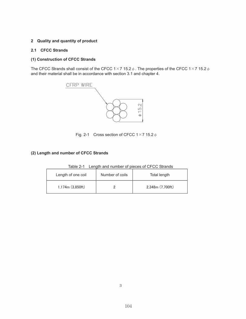
3
2 Quality and quantity of product
2.1 CFCC Strands
(1) Construction of CFCC Strands
The CFCC Strands shall consist of the CFCC 1 7 15.2 . The properties of the CFCC 1 7 15.2and their material shall be in accordance with section 3.1 and chapter 4.
Fig. 2-1 Cross section of CFCC 1 7 15.2
(2) Length and number of CFCC Strands
Table 2-1 Length and number of pieces of CFCC Strands
Length of one coil Number of coils Total length
104

4
2.2 Anchoring devices
(1) Details of Anchoring devices
The anchoring device shall consist of the wedge, sleeve and coupler in Fig. 2-2. The details of the wedge, sleeve and coupler shall be as shown in Fig. 2-3. The configuration of the mesh sheet shall be as shown in Fig. 2-4. The appearance of the braid grip shall be as shown in Pic. 2-1. The properties of the wedge, sleeve and coupler shall be in accordance with chapter 4.
Fig. 2-2 Schematic of anchoring devices
105

5
Wedge (4 pieces in 1 set)
Sleeve
Coupler
Fig. 2-3 Shapes of the anchoring wedge, sleeve and coupler (Unit: mm)
106

6
Fig. 2-4 Configuration of the mesh sheets (Unit: mm)
Pic. 2-1 Appearance of the braid grip (2) Number of Anchoring devices
Table 2-2 Number of anchoring devices Item Number of items Extra amount Total
One braid grip is divided into three. Therefore, 17 braid grips are equivalent to 51
Polinet ®
Sheets
600
25
Stainless steel mesh sheets
107

7
2.3 CFCC Ties
(1) Construction of CFCC Ties
The CFCC Ties shall consist of the CFCC U 5.0 . The properties of the CFCC U 5.0 and their material shall be in accordance with section 3.3 and chapter 4.
Fig. 2-5 Cross section of CFCC U 5.0
(2) Shapes and number of CFCC Ties
The radius of inscribed circle of bent part R is planed to be 10.85 mm. Tolerances of the dimensions are +0.5”, -0.0”.
Fig. 2-6 Bending detail of CFCC Ties
108

8
Fig. 2-7 Turning detail of CFCC Ties
Table 2-3 Number of CFCC Ties
Type Total number of turns Length of CFCC Number of pieces
’
’
109

9
3 Specifications
3.1 CFCC Strands
The CFCC Strands shall comply with the specifications as shown in Table 3-1.
Table 3-1 Specifications of CFCC Strands of CFCC 1 7 12.5 Unit Nominal Tolerance
Construction 1 7Diameter mm 15.2Effective cross sectional area mm2 115.6Linear density g/m 221Breaking load kN 270 270 or above Tensile modulus kN/mm2 155
Standard value
According to the ACI committee reports (ACI 440.4R-04), the recommended maximum jacking stresses for CFRP tendons are 65% of their ultimate strength, but in this project, the CFCC strands shall be stressed to 75 of their breaking loads.
3.2 Anchoring devices
While the CFCC strands are stressed, the temperature of the anchoring devices shall not exceed 50 degrees Celsius (122 degrees Fahrenheit).
3.3 CFCC Ties
The CFCC Ties shall comply with the specifications as shown in Table 3-2.
Table 3-2 Specifications of CFCC Ties of CFCC U 5.0 Unit Nominal Tolerance
Construction U Diameter mm 5.0Effective cross sectional area mm2 15.2Linear density g/m 30Breaking load kN 38 38 or above Tensile modulus kN/mm2 167
Standard value
110
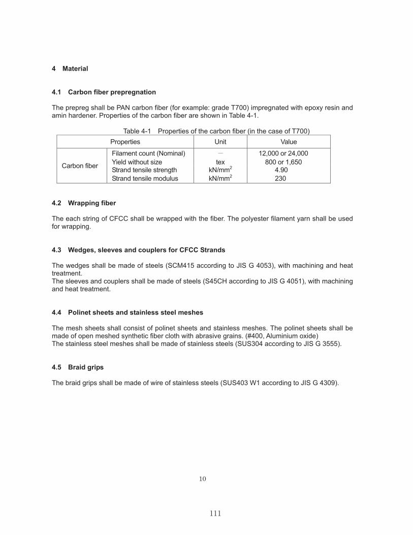
10
4 Material
4.1 Carbon fiber prepregnation
The prepreg shall be PAN carbon fiber (for example: grade T700) impregnated with epoxy resin and amin hardener. Properties of the carbon fiber are shown in Table 4-1.
Table 4-1 Properties of the carbon fiber (in the case of T700) Properties Unit Value
Carbon fiber
Filament count (Nominal) 12,000 or 24,000 Yield without size tex 800 or 1,650 Strand tensile strength kN/mm2 4.90 Strand tensile modulus kN/mm2 230
4.2 Wrapping fiber
The each string of CFCC shall be wrapped with the fiber. The polyester filament yarn shall be used for wrapping.
4.3 Wedges, sleeves and couplers for CFCC Strands
The wedges shall be made of steels (SCM415 according to JIS G 4053), with machining and heat treatment. The sleeves and couplers shall be made of steels (S45CH according to JIS G 4051), with machining and heat treatment.
4.4 Polinet sheets and stainless steel meshes
The mesh sheets shall consist of polinet sheets and stainless meshes. The polinet sheets shall be made of open meshed synthetic fiber cloth with abrasive grains. (#400, Aluminium oxide) The stainless steel meshes shall be made of stainless steels (SUS304 according to JIS G 3555).
4.5 Braid grips
The braid grips shall be made of wire of stainless steels (SUS403 W1 according to JIS G 4309).
111

11
5 Test and inspection
5.1 Items and number of sampling
The test and inspection shall be subjected on the items and the numbers of sampling as shown in Table 5-1. Table 5-1 Items and number of sampling for test and inspection Item Number of samplingAcceptance inspection
Carbon fiber Type, quantity Each acceptance Resin Type, quantity Each acceptance Wrapping fiber Type, quantity Each acceptance Wedge, sleeve, coupler Type, quantity Each acceptance Polinet sheet Type, quantity Each acceptance Stailess steel mesh Type, quantity Each acceptance Braid grip Type, quantity Each acceptance
In-process inspection
CFCC 1 7 15.2 Diameter, pitch, linear density Five for each lot Tensile test Five for each lot
CFCC U 5.0CFCC tie
Diameter, linear density Five for each lot Tensile test Five for each lot Shape Earch piece Dimension Earch piece Appearance Earch piece
Shippinginspection
CFCC strand Length Every cable Quantity Each package Shipping mark Each package
CFCC tie Quantity Each package Shipping mark Each package
5.2 Method of test and inspection of CFCC
Test for CFCC 1 7 15.2 and CFCC U 5.0
Five 1.5 m long test pieces shall be cut from each lot of CFCC 1 x 7 15.2 and CFCC U 5.0to measure the diameter, pitch, and linear density. Each terminal of test pieces shall be fixed into a socket with filling HEM (Highly expansive material) to conduct the tensile test.
The tensile modulus shall be calculated according to the slope of the load . The length of the gauge of the extensometer shall be 500 mm.
The elongation at break shall be calculated by extrapolation of the load - elongation curve up to the breaking point.
The method of tensile test shall conform to JSCE-E531.
112

12
6 Packing and indication
(1) Packing detail
Table 6-1 Packing List
Pack-age No.
Description Quantity Dimention
(mm) Weight (kg)
m pieces Net Gross
1 CFCC strands CFCC 1 7 15.2 1174 2 1802 1802 1185 520 1005
2 CFCC ties “40’ pile” CFCC U 5.0 207 3 900 650 735 19 30
3 CFCC ties “100’ pile” CFCC U 5.0 425 2 1100 650 735 26 38
4 Anchoring devices
Wedges - 40
950 850 480 302 314
Sleeves - 40 Coupler - 40
Mesh sheets - 50 Braid grip 1.5 17
O ring - 50 Jig - 2
Fig. 6-1 Detail of Package No.1
113

13
Fig. 6-2 Detail of Package No.2 Fig. 6-3 Detail of Package No.3
Fig. 6-4 Detail of Package No.4
114

14
(2) Indication
The label shall be attached on the each product. And as the following, the indication shall be attached on the each packing.
Name of Products
Quantity
Weight N.W.T
G.W.T
Check Mark
Manufacturing Company :
Tokyo Rope Mfg. Co., Ltd.
Manufacturing Factory :
Tokyo Rope Mfg. Co., Ltd. Gamagori CFCC Factory
115

15
7 Documents to be submitted
Tokyo Rope shall submit the test report for CFCC. The test report shall include the following documents.
(1) Test results of CFCC
The test results of CFCC 1 7 15.2 and CFCC U 5.0 shall include the following:
Diameter; Direction and pitch of lay (only CFCC 1 7 15.2 ); Linear density; Breaking load; Tensile modulus; Elongation at break;
116
COUPLING DEVICE MANUAL FROMTOKYO ROPE
117

118

119

120

121

122

123

124

125

126

127

128

129

APPENDIX B
CONCRETE MIX DESIGN
Note: The first two pages in this appendix contain compression strength test data
and the concrete mix design that were provided by Gate before the piles were cast,
to help in deciding to use the SCC mix design. This data is NOT on the specific
batches used in the casting of the piles for this research.
The third (3rd) through sixth (6th) pages are copies of the batch tickets for the mix
that was used for this research.
130

131

132

133

134

135

136

APPENDIX C
STRAND TEMPLATE LAYOUT AND
PILE DETAILS
137

Strand Template for Gate PrecastCompany’s Casting Bed
138

139

Plans for 40-ft-long Pile. Markups (in red)are Changes Made from September 2012 to
July 2013 Casting
140

15.6
mm
(0.
6")
15.6
mm
(0.
6")
39.4
5
15.6
mm
(0.
6")
4 co
rner
bar
s st
ress
ed to
5 k
eac
h.
141

Plans for 100-ft-long Pile. Markups (inred) are Changes Made from September
2012 to July 2013 Casting
142

39.4
54
corn
er b
ars
stre
ssed
to 5
k e
ach.
15.6
mm
(0.
6")
15.6
mm
(0.
6")
15.6
mm
(0.
6")
143

APPENDIX D
PRESTRESS LOSS CALCULATIONS
144

145

146

147

APPENDIX E
PILE DRIVING TESTS AND REPORTS
148

PILE TEST SITE: SOIL BORING DATAAND PLAN & ELEVATION SHEET
149
150
151

152

153

PILE DRIVING DATA FORPRODUCTION PILES NEAR TESTPILES 1 AND 2 (FOR COMPARISON
PURPOSES)
154

155

156

157

158
159

160
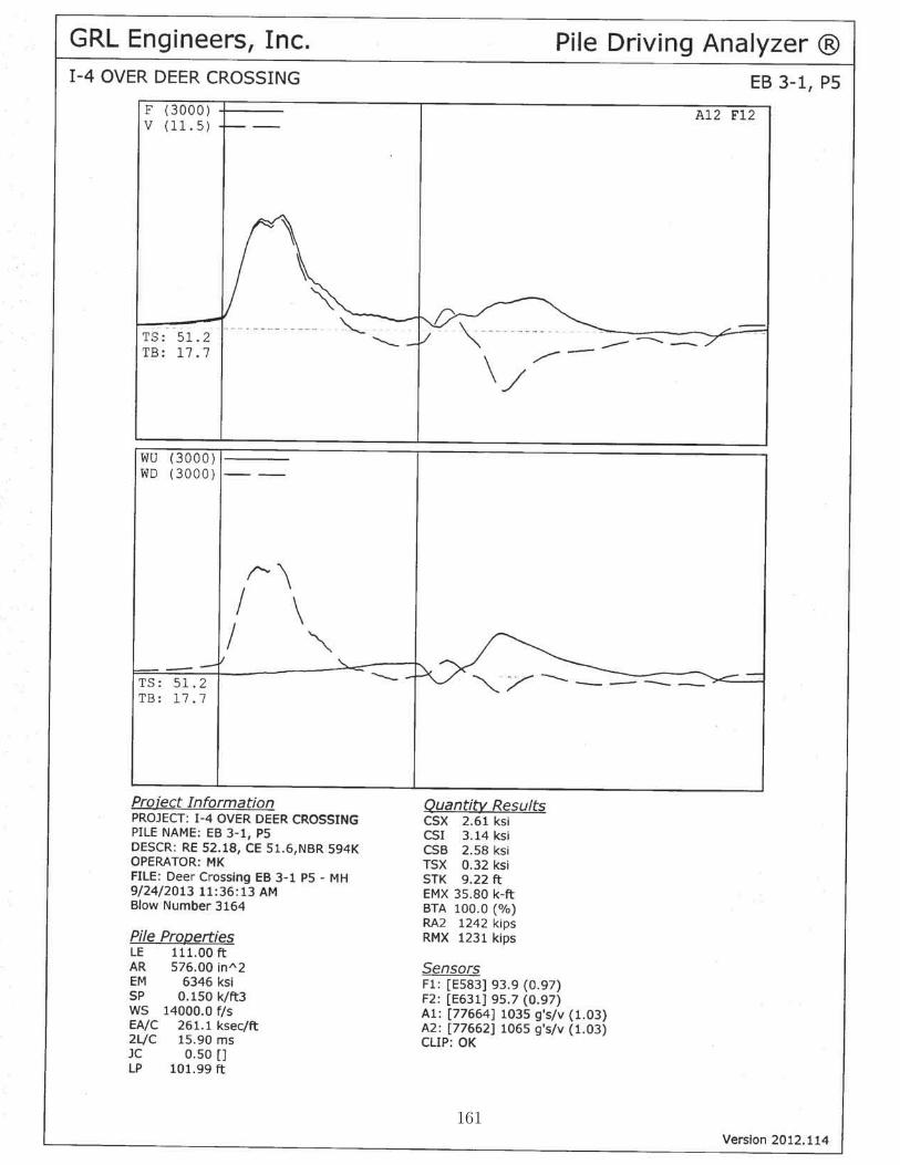
161

162

163

164

165

166

167

168

169

170

171

172

EDC DATA AND REPORT BYAPPLIED FOUNDATION TESTING,
INC.
173

���
������������ �����������������
��������������� !������ �"��#$��
�%��%�&
��'�
���(��
Smar
tPile
(TM
) Rev
iew
Ver
sion
4.04
1bD
isab
led
Erro
r Det
ectio
n Le
vels
:N
one
FSU
Car
bon
Fibe
r Res
earc
hEn
d B
ent 3
1����
1**
War
ning
: Rep
eate
d M
echa
nica
l Err
ors
Det
ecte
d, S
eek
Furt
her P
rofe
ssio
nal D
ata
Ana
lysi
s
CEI
Nam
eD
on R
ober
tson
Stru
ctur
eE
nd B
ent 3
1
Com
pany
Nam
eA
pplie
d Fo
unda
tion
Test
ing
Pile
Num
ber
1
C
ityG
reen
Cov
e S
prin
gsPi
le L
engt
h10
0 F
eet
Stat
eFl
orid
aPi
le M
arke
r Inc
rem
ent
1 F
eet
Zip
3204
3Se
t Che
ck M
arke
r Inc
rem
ent
1 in
ches
Cer
tific
atio
n ID
000F
L000
001
Top
Gag
e to
Pile
Top
48 in
ches
Phon
e N
umbe
r90
4284
1337
Tip
Gag
e to
Pile
Tip
24 in
ches
d D
imen
sion
24 in
ches
Mid
Gag
e to
Pile
Tip
588
inch
esTo
p C
ross
-Sec
tion
Are
a57
6 in
ches
2
Proj
ect N
ame
FSU
Car
bon
Fibe
r Res
earc
hTi
p C
ross
-Sec
tion
Are
a57
6 in
ches
2C
ityD
elan
dM
odul
us o
f Ela
stic
ity60
46.8
2999
2 K
SI
Stat
eFl
Con
cret
e Sp
ecifi
c W
eigh
t0.1
45 K
/ft 3
Cou
nty/
Dis
tric
tD
5W
ave
Spee
d13
900
Fee
t/sec
Proj
ect N
umbe
r (D
OT)
4084
64-1
-52-
01Fi
xed
Jc D
ampi
ng C
oeffi
cien
t0.4
Pr
ojec
t Des
crip
tion
FSU
Car
bon
Fibe
r Res
earc
h P
iles
Pile
Tip
UP
Soil
Rat
e Fa
ctor
0.92
St
ruct
ure
7902
06A
ir H
amm
er/M
ultip
eak
FALS
E
Des
crip
tion
I-4 W
ildlif
e C
ross
ing
Ham
mer
La
titud
eN
omin
al B
earin
g R
esis
tanc
e1
Ton
sLo
ngitu
deTe
nsio
n R
esis
tanc
e1
Ton
sM
inim
um T
ip E
leva
tion
1 F
eet
Jet/P
reFo
rm E
leva
tion
1 F
eet
Pile
Cut
-Off
Elev
atio
n1
Fee
tR
adio
1 ID
00.A
0.96
.30.
2D.4
3
Rad
io 1
FW
Ver
sion
517
����
�����
������
�����
����������
� ��
������
���
������������ �
�����
����������� ����
�����������
���
�
Dis
plac
emen
t (F
eet)
Blo
w N
umbe
rB
low
s pe
r Foo
t to
Dis
pS
troke
/BP
M
(Fee
t)E
nerg
y (K
ips-
ft)Fi
xed
Jc
Cap
acity
(Kip
s)U
F C
apac
ity
(Kip
s)W
ave
Spe
ed
(Fee
t/sec
)
Top
Com
pres
sion
(K
si)
Tip
Com
pres
sion
(K
si)
Max
Ten
sion
(K
si)
MP
ITo
p P
relo
ad
Del
ta (u
Stra
in)
Tip
Pre
load
D
elta
(uS
train
)-2
2.00
110
4.5
19.0
137.
613
0.0
1467
9.9
1.4
0.3
1.1
94.2
-27.
4-5
4.2
-24.
0017
55.
721
.719
7.4
223.
814
487.
31.
70.
31.
295
.8-2
.00.
6-2
5.00
236
5.7
22.2
218.
725
7.2
1443
8.4
1.8
0.3
1.2
100.
0-1
.60.
3-2
6.00
296
5.7
21.8
246.
728
7.2
1439
8.3
1.8
0.3
1.2
98.5
-1.4
-2.4
-27.
0036
75.
823
.123
6.4
266.
414
348.
71.
80.
41.
310
0.0
-1.9
-5.9
-28.
0043
76.
025
.321
8.3
233.
014
325.
31.
90.
41.
397
.3-1
.1-7
.2-2
9.00
507
5.9
26.1
198.
121
2.7
1430
4.0
1.9
0.4
1.2
97.7
-0.4
-3.9
-30.
0060
106.
027
.219
2.0
203.
814
272.
71.
90.
41.
398
.0-0
.5-5
.6-3
1.00
7010
6.0
27.8
170.
618
3.0
1423
7.0
1.9
0.4
1.3
97.9
-0.7
-5.0
-32.
0080
106.
028
.615
5.7
176.
314
205.
42.
00.
51.
398
.4-0
.5-5
.1-3
3.00
9212
6.2
30.4
148.
318
6.4
1417
6.8
2.0
0.5
1.3
99.0
-0.5
-4.7
-34.
0010
513
6.2
31.1
151.
819
4.7
1416
3.2
2.0
0.5
1.3
99.0
0.3
-5.1
-35.
0012
015
6.4
31.4
168.
920
8.2
1413
7.9
2.1
0.5
1.3
99.0
0.7
-5.4
-36.
0013
313
6.4
31.6
184.
020
8.0
1412
2.4
2.1
0.6
1.3
99.4
1.0
-3.3
-37.
0014
916
6.5
31.9
188.
920
7.3
1411
6.9
2.1
0.6
1.3
100.
01.
4-3
.7-3
8.00
172
216.
229
.321
5.7
251.
814
106.
92.
00.
61.
210
0.0
2.4
-4.4
-39.
0019
725
6.2
29.6
218.
530
5.3
1411
7.8
2.0
0.7
1.2
100.
02.
7-6
.3-4
0.00
223
266.
430
.522
9.0
353.
514
124.
02.
10.
71.
210
0.0
3.0
-5.4
-41.
0024
926
6.6
31.9
254.
134
9.0
1412
1.7
2.2
0.8
1.2
100.
03.
9-6
.0-4
2.00
275
267.
438
.325
4.0
417.
414
101.
52.
40.
81.
310
0.0
2.8
-8.0
-43.
0030
530
7.4
38.8
251.
239
5.8
1410
6.8
2.4
0.8
1.3
100.
04.
0-8
.1-4
4.00
332
277.
337
.525
2.5
321.
414
107.
62.
30.
71.
210
0.0
3.4
-8.4
-45.
0035
018
7.2
37.5
276.
424
8.5
1408
3.1
2.3
0.6
1.2
100.
02.
9-5
.4
Driv
e D
urat
ion:
From
01-
23-2
014
14:3
7:06
to 0
1-23
-201
4 16
:46:
21
Pile
Info
rmat
ion
�)�������*
����
� �� !
Proj
ect I
nfor
mat
ion
Use
r Inf
orm
atio
n
����
174

���
������������ �����������������
��������������� !������ �"��#$��
�%��%�&
��'�
���(��
Dis
plac
emen
t (F
eet)
Blo
w N
umbe
rB
low
s pe
r Foo
t to
Dis
pS
troke
/BP
M
(Fee
t)E
nerg
y (K
ips-
ft)Fi
xed
Jc
Cap
acity
(Kip
s)U
F C
apac
ity
(Kip
s)W
ave
Spe
ed
(Fee
t/sec
)
Top
Com
pres
sion
(K
si)
Tip
Com
pres
sion
(K
si)
Max
Ten
sion
(K
si)
MP
ITo
p P
relo
ad
Del
ta (u
Stra
in)
Tip
Pre
load
D
elta
(uS
train
)-4
6.00
367
177.
336
.930
7.4
257.
314
053.
92.
30.
61.
210
0.0
3.0
-5.9
-47.
0038
922
7.4
37.3
327.
428
5.5
1405
8.2
2.4
0.5
1.2
100.
03.
5-4
.5-4
8.00
411
227.
536
.834
5.9
313.
114
084.
32.
40.
51.
299
.13.
3-6
.5-4
9.00
433
227.
435
.435
4.2
332.
114
073.
42.
30.
51.
197
.14.
0-5
.8-5
0.00
455
227.
737
.637
0.0
349.
214
038.
72.
40.
61.
194
.73.
6-6
.2-5
1.00
478
237.
939
.139
5.9
374.
714
024.
22.
50.
61.
191
.73.
6-7
.4-5
2.00
506
288.
038
.443
1.8
418.
314
013.
82.
40.
61.
188
.15.
0-5
.6-5
3.00
536
308.
441
.744
2.1
426.
714
022.
72.
60.
71.
185
.24.
9-6
.5-5
4.00
572
368.
844
.551
5.8
490.
514
008.
52.
60.
71.
283
.94.
0-8
.6-5
5.00
594
228.
843
.453
6.9
517.
813
889.
12.
70.
71.
184
.14.
7-6
.8-5
6.00
626
328.
747
.049
2.6
449.
613
905.
22.
70.
81.
283
.15.
0-8
.7-5
7.00
657
318.
848
.249
6.9
457.
613
905.
52.
80.
81.
381
.65.
3-1
1.7
-58.
0068
730
8.7
48.2
480.
143
8.9
1388
5.2
2.8
0.8
1.4
81.2
5.8
-11.
5-5
9.00
719
328.
747
.352
1.1
473.
913
899.
92.
90.
81.
481
.06.
4-1
3.0
-60.
0074
728
8.8
48.3
557.
251
5.0
1388
1.1
3.0
0.8
1.3
80.5
5.5
-13.
3-6
1.00
774
278.
849
.157
4.1
531.
513
864.
53.
00.
81.
580
.05.
6-1
3.7
-62.
0080
430
8.8
49.5
546.
849
8.9
1386
9.3
3.0
0.8
1.5
79.5
6.4
-18.
2-6
3.00
839
358.
848
.457
8.1
528.
313
840.
83.
10.
81.
480
.27.
2-2
1.4
-64.
0086
930
8.9
49.7
588.
352
1.9
1379
4.6
3.1
0.8
1.3
81.0
8.0
-23.
2-6
5.00
899
309.
049
.063
4.2
563.
913
769.
03.
20.
81.
381
.77.
6-2
4.6
-66.
0093
132
9.1
48.6
649.
657
6.3
1378
1.4
3.2
0.7
1.3
83.3
8.4
-22.
9-6
7.00
961
309.
150
.454
7.1
462.
213
801.
83.
20.
71.
484
.78.
8-2
7.1
-68.
0098
625
9.2
48.4
637.
655
1.2
1377
9.4
3.2
0.7
1.4
85.4
10.3
-28.
4-6
9.00
1021
359.
450
.454
0.7
430.
213
774.
83.
30.
61.
585
.912
.5-3
0.1
-70.
0010
5635
9.4
51.5
487.
533
6.3
1377
9.7
3.2
0.6
1.5
87.0
14.1
-32.
8-7
1.00
1092
369.
351
.051
4.4
346.
113
753.
73.
20.
61.
687
.714
.1-3
2.8
-72.
0011
2634
9.4
48.7
515.
036
2.8
1373
8.2
3.2
0.5
1.6
88.0
13.9
-32.
2-7
3.00
1161
359.
248
.842
6.9
238.
913
726.
43.
10.
51.
488
.614
.0-3
1.2
-74.
0012
0342
9.3
43.2
489.
740
2.1
1371
3.6
3.0
0.5
1.3
89.0
13.8
-29.
9-7
5.00
1242
399.
341
.049
8.2
401.
013
683.
43.
00.
51.
189
.214
.2-2
9.8
-76.
0012
8240
9.4
40.8
498.
435
0.3
1370
1.0
2.9
0.4
1.0
90.5
13.2
-29.
4-7
7.00
1320
359.
238
.247
0.1
310.
113
675.
92.
70.
41.
191
.613
.2-3
0.8
-78.
0013
6040
8.4
36.7
485.
033
2.0
1367
9.2
2.5
0.4
0.9
92.8
13.7
-21.
8-7
9.00
1423
638.
942
.648
6.5
310.
013
651.
62.
90.
50.
991
.513
.8-1
8.2
-80.
0014
9370
9.0
43.8
687.
952
1.3
1380
6.1
2.9
0.8
0.7
89.0
14.7
-4.3
-81.
0015
6067
9.0
43.9
773.
971
5.9
1400
3.9
2.9
1.1
0.6
86.6
15.6
-2.0
-82.
0016
4080
9.1
45.6
838.
478
4.1
1407
4.3
2.9
1.4
0.6
85.2
12.9
-4.4
-83.
0017
2080
9.2
46.6
877.
384
2.6
1414
9.8
3.0
1.6
0.6
84.9
11.9
-4.9
-84.
0018
1595
9.3
46.5
898.
388
3.4
1422
7.2
3.0
1.6
0.7
84.7
12.2
-4.7
-85.
0019
0388
9.4
47.8
864.
284
8.0
1426
0.2
3.1
1.6
0.9
86.0
12.1
-4.4
-86.
0019
8784
9.4
49.0
786.
577
4.8
1417
8.7
3.2
1.5
1.1
86.1
13.3
-4.4
-87.
0020
7588
9.5
50.2
787.
476
2.5
1409
3.9
3.3
1.4
1.1
87.3
13.6
-5.0
-88.
0021
2954
9.5
50.8
736.
470
4.8
1406
5.2
3.4
1.2
1.1
87.8
14.0
-5.7
-89.
0021
8859
9.5
51.0
667.
763
7.9
1402
7.1
3.4
1.1
1.2
86.4
14.7
-8.4
-90.
0022
4658
9.5
50.4
625.
058
7.9
1402
4.1
3.5
1.1
1.1
86.0
15.5
-11.
4-9
1.00
2300
549.
449
.361
3.4
561.
914
025.
13.
40.
91.
386
.816
.8-1
2.2
-92.
0023
5151
9.5
50.0
608.
555
8.4
1402
2.5
3.4
0.9
1.2
87.0
15.6
-10.
0-9
3.00
2401
509.
448
.754
1.6
506.
913
990.
03.
30.
91.
187
.616
.4-1
0.7
-94.
0024
5150
9.5
46.6
548.
650
6.9
1402
6.9
3.2
0.8
1.0
88.6
18.1
-11.
6-9
5.00
2509
589.
544
.956
7.8
489.
714
058.
83.
10.
80.
990
.318
.9-9
.1-9
6.00
2566
579.
744
.363
7.6
499.
014
076.
43.
00.
80.
793
.919
.3-6
.8-9
7.00
2624
589.
742
.868
0.6
529.
514
054.
83.
00.
80.
597
.718
.8-4
.4-9
8.00
2690
669.
843
.171
1.6
551.
213
994.
63.
20.
90.
699
.419
.5-3
.1-9
9.00
2736
469.
944
.374
6.1
572.
313
938.
23.
30.
90.
510
0.0
20.8
-1.9
-99.
0027
36
9.9
45.0
726.
057
2.0
1392
1.7
3.4
1.0
0.4
100.
020
.13.
1-9
9.02
2737
10
.146
.773
5.0
614.
013
921.
93.
41.
00.
510
0.0
20.4
-1.3
-99.
0427
38
9.8
47.1
737.
060
9.0
1392
6.7
3.5
1.0
0.5
100.
021
.6-3
.2-9
9.07
2739
9.
845
.170
8.0
594.
013
926.
73.
41.
00.
510
0.0
23.0
-3.6
-99.
0927
40
9.7
45.3
718.
056
8.0
1392
6.7
3.5
1.0
0.4
100.
021
.6-2
.8-9
9.11
2741
9.
743
.872
2.0
592.
013
926.
73.
41.
00.
510
0.0
23.0
-2.8
-99.
1327
42
9.6
46.1
690.
060
3.0
1392
6.7
3.4
1.0
0.4
100.
023
.0-2
.5-9
9.15
2743
9.
845
.773
3.0
611.
013
931.
63.
40.
90.
410
0.0
22.2
2.7
-99.
1727
44
9.7
48.4
730.
056
4.0
1393
1.8
3.6
1.0
0.5
99.0
23.0
1.2
-99.
2027
45
9.7
46.7
731.
061
4.0
1393
6.5
3.5
1.0
0.4
99.0
23.0
-0.1
175

���
������������ �����������������
��������������� !������ �"��#$��
�%��%�&
��'�
���(��
Dis
plac
emen
t (F
eet)
Blo
w N
umbe
rB
low
s pe
r Foo
t to
Dis
pS
troke
/BP
M
(Fee
t)E
nerg
y (K
ips-
ft)Fi
xed
Jc
Cap
acity
(Kip
s)U
F C
apac
ity
(Kip
s)W
ave
Spe
ed
(Fee
t/sec
)
Top
Com
pres
sion
(K
si)
Tip
Com
pres
sion
(K
si)
Max
Ten
sion
(K
si)
MP
ITo
p P
relo
ad
Del
ta (u
Stra
in)
Tip
Pre
load
D
elta
(uS
train
)-9
9.22
2746
9.
647
.373
5.0
612.
013
937.
03.
61.
00.
599
.024
.50.
1-9
9.24
2747
9.
947
.171
3.0
599.
013
936.
53.
51.
00.
499
.023
.5-0
.5-9
9.26
2748
9.
848
.270
0.0
602.
013
937.
03.
61.
10.
699
.024
.50.
5-9
9.28
2749
9.
646
.370
6.0
604.
013
936.
53.
51.
00.
499
.023
.6-0
.2-9
9.30
2750
9.
447
.869
5.0
593.
013
937.
03.
61.
00.
599
.023
.01.
2-9
9.33
2751
9.
547
.070
0.0
602.
013
931.
63.
51.
10.
599
.023
.8-4
.7-9
9.35
2752
9.
648
.269
5.0
615.
013
931.
83.
61.
10.
598
.024
.12.
3-9
9.37
2753
9.
649
.272
0.0
616.
013
931.
63.
71.
00.
699
.024
.5-0
.6-9
9.39
2754
9.
748
.372
9.0
641.
013
931.
83.
61.
10.
698
.024
.5-1
.6-9
9.41
2755
9.
848
.174
7.0
580.
013
931.
63.
71.
10.
698
.024
.50.
5-9
9.43
2756
9.
949
.373
4.0
637.
013
931.
83.
71.
10.
598
.023
.00.
5-9
9.46
2757
9.
948
.273
1.0
630.
013
926.
73.
71.
10.
598
.024
.5-0
.2-9
9.48
2758
9.
847
.973
9.0
637.
013
926.
73.
61.
10.
598
.024
.50.
5-9
9.50
2759
9.
748
.673
9.0
623.
013
926.
73.
71.
00.
598
.024
.51.
2-9
9.52
2760
9.
847
.472
5.0
625.
013
926.
73.
61.
00.
698
.024
.50.
1-9
9.54
2761
9.
746
.270
9.0
626.
013
921.
83.
51.
00.
498
.024
.52.
3-9
9.57
2762
9.
649
.074
6.0
654.
013
921.
53.
71.
10.
598
.025
.51.
6-9
9.59
2763
9.
849
.974
2.0
661.
013
921.
83.
81.
10.
698
.024
.50.
9-9
9.61
2764
9.
948
.077
7.0
669.
013
916.
43.
71.
10.
698
.027
.4-1
.7-9
9.63
2765
9.
849
.378
0.0
664.
013
912.
03.
81.
10.
697
.028
.22.
0-9
9.65
2766
9.
845
.478
2.0
625.
013
911.
23.
71.
10.
698
.029
.62.
0-9
9.67
2767
9.
751
.575
1.0
638.
013
912.
03.
81.
10.
597
.030
.43.
8-9
9.70
2768
10
.054
.474
2.0
624.
013
911.
23.
81.
10.
597
.030
.9-0
.2-9
9.72
2769
9.
754
.074
9.0
648.
013
912.
03.
81.
10.
597
.030
.42.
7-9
9.74
2770
9.
753
.474
4.0
628.
013
911.
23.
81.
10.
597
.031
.82.
7-9
9.76
2771
9.
654
.375
5.0
647.
013
912.
03.
91.
10.
597
.033
.30.
1-9
9.78
2772
9.
851
.869
7.0
606.
013
916.
44.
01.
10.
897
.034
.80.
9-9
9.80
2773
8.
526
.559
5.0
454.
013
912.
02.
50.
70.
297
.034
.8-1
.4-9
9.83
2774
6.
513
.839
3.0
291.
013
911.
21.
40.
50.
096
.035
.8-5
.0-9
9.85
2775
404.
511
.320
2.0
177.
013
899.
30.
80.
30.
096
.034
.8-4
.9
176

��������� �����������!��:��� �� ���;���";���������� ������"�
��;��;� ����;����;
FSU Carbon Fiber Research End Bent 31 ��� 1 2
�(�����"������������
�;:��
�:��
��:��
��:��
��:��
��:��
��:��
��:��
�::��
�� ;�� :�� ��� ��� ��� ��� ��� ��� �� ;��
��������*�������!�
������������������������� ������������������
� �!"!��������#�$% � %!� ������&� '�������� ���
�;:��
�:��
��:��
��:��
��:��
��:��
��:��
��:��
�::��
�� ��� ;�� ;��� :�� :��� ��� ���� ��� ����
�������*�������!�
�%���%!�&����% ������� �����%!�&����% ������� ����� ��% �������
�;:��
�:��
��:��
��:��
��:��
��:��
��:��
��:��
�::��
�;�� ���� �� ��� ;�� ;���
��������
��"�����"����� ������*�������!�
�%���&��%����������"��&�� �� �����&��%����������"��&�� �� ���
�;:��
�:��
��:��
��:��
��:��
��:��
��:��
��:��
�::��
�� ;�� :�� ��� ��� ��� ���
������� ��� ����*�������!�
��&%(�)���������� � �&'�������*+��
�;:��
�:��
��:��
��:��
��:��
��:��
��:��
��:��
�::��
;:�� ;:��� ;��� ;���� ;��� ;���� ;���
��*����*�������!�
��#�������������)����� ��#��������
Dis
plac
emen
t (Fe
et)�
Dis
plac
emen
t (Fe
et)�
Dis
plac
emen
t (Fe
et)�
Dis
plac
emen
t (Fe
et)�
Dis
plac
emen
t (Fe
et)�
177

178

PDA DATA AND REPORT BY GRLENGINEERS, INC.
179

Subject: FW: PDA Testing Results - CFCC PilesFrom: "Potter, William" <[email protected]>Date: Tue, 28 Jan 2014 16:18:49 +0000To: Michelle Roddenberry <[email protected]>
fyi
Will Potter, P.E.Florida Department of TransportationM. H. Ansley Structures Research Center850-921-7106
From: Herrera, RodrigoSent: Monday, January 27, 2014 8:10 AMTo: Robertson, Robert; Jones, Larry; Fallaha, Sam; Potter, WilliamSubject: FW: PDA Testing Results - CFCC Piles
FYI Rodrigo Herrera, P.E.Asst. State Geotechnical EngineerFlorida Department of Transportation605 Suwannee Street, MS 33Tallahassee, FL 32399-0450Phone: (850) 414-4377
From: [email protected] [mailto:[email protected]]Sent: Sunday, January 26, 2014 10:10 PMTo: Hipworth, Robert; Herrera, RodrigoCc: [email protected]: PDA Testing Results - CFCC Piles
Gentlemen,
This report presents the results of the Pile Driving Analyzer® (PDA) dynamic pile testing performed during the installation of two 24-inch square, 100 feet long, experimental prestressed concrete piles utilizing CFCC (carbon fiber composite cable) prestressing strands and spiral reinforcements. Information regarding the structural pile design and specifics about these research piles may be found in the FDOT’s Structures Office documents. Two each reusable strain transducers and accelerometers were bolted on opposite pile sides five feet below each pile top for the PDA data acquisition. An APE D 46-42 open-ended (i.e., single-acting) diesel hammer with a ram weight of 10.1 kips was used to drive and test the piles. A pile driving inspector on site monitored the pile installations and kept pile driving blow count logs. The piles were driven at the I-4 widening project site in District 5 close to the Deer Crossing Bridge No.
180

790207 near End Bent 3-1 in the vicinity of soil boring DC-1. The two piles were referred to as: CFCC West Pile N1 and CFCC East Pile N2.
The attached pdf file contains the PDA testing results, along with copies of the inspector’s pile driving logs (as provided to us) and the soil boring. The PDA w01 data files are too large to attach here and can be obtained by the following weblinks:
CFCC EAST PILE N2-MH.w01
https://grlfl.pile.com:5001/fbsharing/60kPljez
CFCC WEST PILE N1-MH.w01
https://grlfl.pile.com:5001/fbsharing/u1eivlO0
These links will be available for one month. The server will ask for a password, which is fdot (all lowercase).
The PDA results in the attached file are presented in table and graph forms as functions of hammer blow number, pile “penetration” depth below the template reference used by the inspector in recording the pile driving blow counts, and pile tip elevations. The references had reported elevations of approximately +53 feet, and were approximately seven feet above existing ground surface. The results include:
CSX: maximum measured pile compressing stress at the gages (averaged from the two transducers at opposite pile faces) located five feet below pile top, ksi,
CSI: maximum measured pile compressing stress by the higher of the two individual gages located five feet below pile top, ksi,
CSB: maximum computed pile toe compression stresses, ksi,
TSX: maximum computed pile tension stress throughout pile length, ksi,
STK: hammer ram stroke height, ft,
EMX: maximum energy transferred to the pile top at the gages location, kip-ft,
BTA: pile integrity assessment factor,
RX0: total soil resistance to pile driving (static and dynamic), kips,
RX5: pile static ultimate load bearing capacity computed with a Case Damping Factor Jc = 0.5 based on correlations with CAPWAP data analyses with the RMX Case Method equation obtained from the Test Piles driving program for the production work for the bridge
181
construction, kips.
The data indicated a pile material one-dimensional stresswave speed of 14,050 feet/second, which corresponds to a dynamic elastic modulus of 6,178 ksi assuming a material unit weight of 145 lbs/ft3.
Pile N1 was driven on January 23rd afternoon. Pile top cushion consisted of sheets of plywood with an initial total thickness of 8.75 inches. The pile cushion was changes when the pile had a “penetration” 77 feet below reference. The pile was driven to a final tip elevation of -47 feet. Pile driving was stopped due to concrete spalling at pile top. The pile was subjected to a total of 2,765 hammer blows.
Pile N2 was driven during the morning of January 24th. Pile top cushion consisted of sheets of plywood with a total thickness of 6 inches. The pile cushion was changed at pile “penetrations” below reference of 70, 84, and 93 feet. The pile was driven to a final tip elevation of -51 feet. Pile driving was stopped due to concrete spalling at pile top. The pile was subjected to a total of 3,139 hammer blows. When the pile was at “penetration” below reference of approximately 55 feet, two small cracks (a few feet apart along pile length) were observed in the pile at about mid pile length. These minor cracks evidently did not produce stresswave reflections of the type that would've been characteristically typically present in the test records within the first time cycle of strtesswave travel in the pile. Their presence in the pile may possibly be surmised from the data by the minor distortion to the 2L/c reflection characteristics, reduction in the overall stresswave speed, and overall trend and characteristics in the wave-up records. The pile was subjected to about 2500 additional hammer blows with high stroke heights and pile stress levels after the cracks were observed in the pile without further indications of pile damage.
We appreciate the opportunity to provide our PDA field testing services during the field pile driving phase of these interesting experimental piles. Please confirm receipt of this e-mail and the successful downloading of the data files by the provided weblinks, and let us know if you have any questions or if we may be of further assistance.
Regards,
Mohamad Hussein, P.E.Marty Bixler, P.E.GRL Engineers, Inc.
Attachments:PileDrivingAnalyzerPDATestingResultsPilesN1andN2.pdf 797 KB
182

GRL Engineers, Inc.
Pile Driving Analyzer® (PDA) Dynamic Pile Testing Results Pile Driving Logs (as provided to us by the field inspector)
Site Layout and Soil Boring
24-inch square precast concrete piles with CFCC strands and spirals
Pile N1 Pile N2
183

1
1 -
C
HA
NG
E P
ILE
CU
SH
ION
Tes
t dat
e: 2
3-Ja
n-20
14
Max
Cas
e M
etho
d C
apac
ity (
JC=
0.5)
Max
Cas
e M
etho
d C
apac
ity (
JC=
0)
Blo
w C
ount
O.E
. Die
sel H
amm
er S
trok
e
Ten
sion
Str
ess
Max
imum
Max
Mea
sure
d C
ompr
. Str
ess
PD
IPLO
T V
er. 2
014.
1 -
Prin
ted:
25-
Jan-
2014
GR
L E
ngin
eers
, Inc
. - C
ase
Met
hod
& iC
AP
® R
esul
ts
I-4
DE
ER
CR
OS
SIN
G B
ridge
No.
790
207
- C
FC
C W
ES
T P
ILE
N1
0
CS
X (
ksi)
0
TS
X (
ksi)
0
BLC
(bl
ows/
ft)
0
ST
K (
ft)
0
RX
5 (k
ips)
0
RX
0 (k
ips)
0
B l o w N u m b e r
500
1,00
0
1,50
0
2,00
0
2,50
0
3,00
0
12
34
36
912
500
1,00
01,
500
2,00
0
12
34
3060
9012
050
01,
000
1,50
02,
000
184
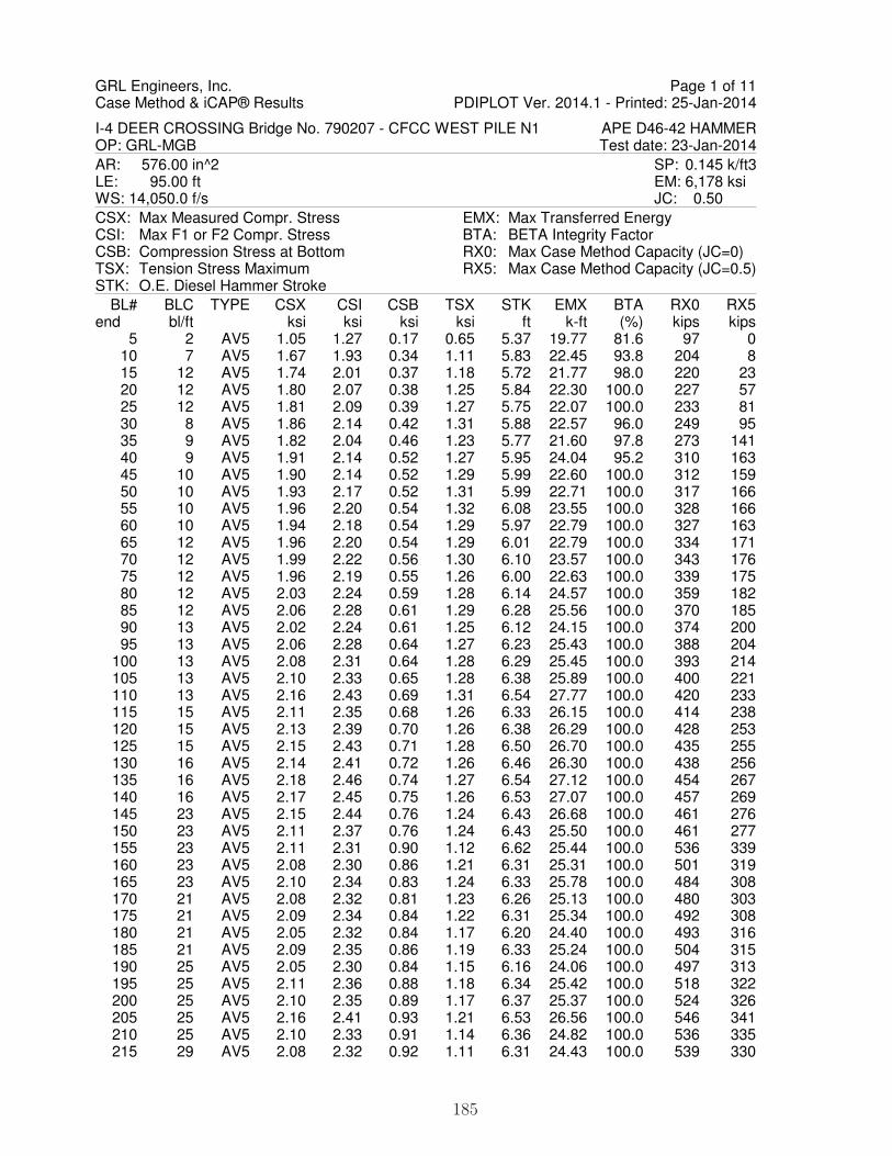
GRL Engineers, Inc.Case Method & iCAP® Results PDIPLOT Ver. 2014.1 - Printed: 25-Jan-2014
I-4 DEER CROSSING Bridge No. 790207 - CFCC WEST PILE N1 APE D46-42 HAMMEROP: GRL-MGB Test date: 23-Jan-2014AR: 576.00 in^2 SP: 0.145 k/ft3LE: 95.00 ft EM: 6,178 ksiWS: 14,050.0 f/s JC: 0.50CSX: Max Measured Compr. StressCSI: Max F1 or F2 Compr. StressCSB: Compression Stress at BottomTSX: Tension Stress MaximumSTK: O.E. Diesel Hammer Stroke
EMX: Max Transferred EnergyBTA: BETA Integrity FactorRX0: Max Case Method Capacity (JC=0)RX5: Max Case Method Capacity (JC=0.5)
BL# BLC TYPE CSX CSI CSB TSX STK EMX BTA RX0 RX5end bl/ft ksi ksi ksi ksi ft k-ft (%) kips kips
5 2 AV5 1.05 1.27 0.17 0.65 5.37 19.77 81.6 97 0 10 7 AV5 1.67 1.93 0.34 1.11 5.83 22.45 93.8 204 8 15 12 AV5 1.74 2.01 0.37 1.18 5.72 21.77 98.0 220 23 20 12 AV5 1.80 2.07 0.38 1.25 5.84 22.30 100.0 227 57 25 12 AV5 1.81 2.09 0.39 1.27 5.75 22.07 100.0 233 81 30 8 AV5 1.86 2.14 0.42 1.31 5.88 22.57 96.0 249 95 35 9 AV5 1.82 2.04 0.46 1.23 5.77 21.60 97.8 273 141 40 9 AV5 1.91 2.14 0.52 1.27 5.95 24.04 95.2 310 163 45 10 AV5 1.90 2.14 0.52 1.29 5.99 22.60 100.0 312 159 50 10 AV5 1.93 2.17 0.52 1.31 5.99 22.71 100.0 317 166 55 10 AV5 1.96 2.20 0.54 1.32 6.08 23.55 100.0 328 166 60 10 AV5 1.94 2.18 0.54 1.29 5.97 22.79 100.0 327 163 65 12 AV5 1.96 2.20 0.54 1.29 6.01 22.79 100.0 334 171 70 12 AV5 1.99 2.22 0.56 1.30 6.10 23.57 100.0 343 176 75 12 AV5 1.96 2.19 0.55 1.26 6.00 22.63 100.0 339 175 80 12 AV5 2.03 2.24 0.59 1.28 6.14 24.57 100.0 359 182 85 12 AV5 2.06 2.28 0.61 1.29 6.28 25.56 100.0 370 185 90 13 AV5 2.02 2.24 0.61 1.25 6.12 24.15 100.0 374 200 95 13 AV5 2.06 2.28 0.64 1.27 6.23 25.43 100.0 388 204
100 13 AV5 2.08 2.31 0.64 1.28 6.29 25.45 100.0 393 214 105 13 AV5 2.10 2.33 0.65 1.28 6.38 25.89 100.0 400 221 110 13 AV5 2.16 2.43 0.69 1.31 6.54 27.77 100.0 420 233 115 15 AV5 2.11 2.35 0.68 1.26 6.33 26.15 100.0 414 238 120 15 AV5 2.13 2.39 0.70 1.26 6.38 26.29 100.0 428 253 125 15 AV5 2.15 2.43 0.71 1.28 6.50 26.70 100.0 435 255 130 16 AV5 2.14 2.41 0.72 1.26 6.46 26.30 100.0 438 256 135 16 AV5 2.18 2.46 0.74 1.27 6.54 27.12 100.0 454 267 140 16 AV5 2.17 2.45 0.75 1.26 6.53 27.07 100.0 457 269 145 23 AV5 2.15 2.44 0.76 1.24 6.43 26.68 100.0 461 276 150 23 AV5 2.11 2.37 0.76 1.24 6.43 25.50 100.0 461 277 155 23 AV5 2.11 2.31 0.90 1.12 6.62 25.44 100.0 536 339 160 23 AV5 2.08 2.30 0.86 1.21 6.31 25.31 100.0 501 319 165 23 AV5 2.10 2.34 0.83 1.24 6.33 25.78 100.0 484 308 170 21 AV5 2.08 2.32 0.81 1.23 6.26 25.13 100.0 480 303 175 21 AV5 2.09 2.34 0.84 1.22 6.31 25.34 100.0 492 308 180 21 AV5 2.05 2.32 0.84 1.17 6.20 24.40 100.0 493 316 185 21 AV5 2.09 2.35 0.86 1.19 6.33 25.24 100.0 504 315 190 25 AV5 2.05 2.30 0.84 1.15 6.16 24.06 100.0 497 313 195 25 AV5 2.11 2.36 0.88 1.18 6.34 25.42 100.0 518 322 200 25 AV5 2.10 2.35 0.89 1.17 6.37 25.37 100.0 524 326 205 25 AV5 2.16 2.41 0.93 1.21 6.53 26.56 100.0 546 341 210 25 AV5 2.10 2.33 0.91 1.14 6.36 24.82 100.0 536 335 215 29 AV5 2.08 2.32 0.92 1.11 6.31 24.43 100.0 539 330
Page 1 of 11
185

GRL Engineers, Inc.Case Method & iCAP® Results PDIPLOT Ver. 2014.1 - Printed: 25-Jan-2014
I-4 DEER CROSSING Bridge No. 790207 - CFCC WEST PILE N1 APE D46-42 HAMMEROP: GRL-MGB Test date: 23-Jan-2014
BL# BLC TYPE CSX CSI CSB TSX STK EMX BTA RX0 RX5end bl/ft ksi ksi ksi ksi ft k-ft (%) kips kips
220 29 AV5 2.15 2.39 0.96 1.15 6.53 26.15 100.0 562 339 225 29 AV5 2.13 2.39 0.96 1.13 6.46 25.56 100.0 562 337 230 29 AV5 2.20 2.47 0.97 1.15 6.63 26.59 100.0 572 345 235 29 AV5 2.18 2.45 0.97 1.13 6.62 26.16 100.0 575 350 240 29 AV5 2.24 2.51 1.00 1.17 6.77 27.48 100.0 592 363 245 25 AV5 2.36 2.62 1.04 1.24 7.24 30.58 100.0 617 369 250 25 AV5 2.41 2.68 1.04 1.28 7.43 31.86 100.0 623 372 255 25 AV5 2.44 2.73 1.08 1.30 7.56 33.02 100.0 635 372 260 25 AV5 2.46 2.74 1.09 1.31 7.57 33.30 100.0 642 377 265 25 AV5 2.41 2.69 1.07 1.27 7.35 31.82 100.0 631 375 270 24 AV5 2.43 2.71 1.08 1.28 7.40 32.30 100.0 639 380 275 24 AV5 2.48 2.78 1.11 1.31 7.63 33.95 100.0 653 385 280 24 AV5 2.45 2.75 1.10 1.28 7.46 32.88 100.0 647 391 285 24 AV5 2.45 2.75 1.10 1.27 7.48 32.81 100.0 649 396 290 24 AV5 2.43 2.73 1.09 1.26 7.42 32.54 100.0 641 387 295 24 AV5 2.46 2.76 1.07 1.28 7.49 32.90 100.0 642 391 300 24 AV5 2.43 2.74 1.07 1.26 7.39 32.54 100.0 634 386 305 24 AV5 2.42 2.72 1.06 1.25 7.39 32.32 100.0 628 384 310 24 AV5 2.38 2.67 1.04 1.22 7.21 31.32 100.0 616 380 315 21 AV5 2.42 2.73 1.06 1.25 7.36 32.58 100.0 623 385 320 21 AV5 2.39 2.70 1.04 1.23 7.26 31.63 100.0 614 386 325 21 AV5 2.40 2.72 1.03 1.25 7.32 31.92 100.0 611 382 330 21 AV5 2.39 2.71 0.97 1.25 7.32 31.17 100.0 599 382 335 21 AV5 2.39 2.71 1.00 1.25 7.28 31.53 100.0 600 379 340 20 AV5 2.38 2.70 1.01 1.24 7.21 31.50 100.0 598 378 345 20 AV5 2.39 2.73 1.01 1.26 7.32 31.95 100.0 602 384 350 20 AV5 2.43 2.78 1.02 1.29 7.45 32.75 100.0 611 396 355 20 AV5 2.43 2.80 1.02 1.29 7.48 32.53 100.0 618 410 360 20 AV5 2.37 2.75 0.99 1.23 7.25 30.68 100.0 602 401 365 20 AV5 2.42 2.81 1.02 1.26 7.43 32.24 100.0 620 407 370 20 AV5 2.43 2.82 1.02 1.28 7.50 32.71 100.0 623 411 375 20 AV5 2.43 2.82 1.01 1.28 7.45 32.42 100.0 621 415 380 21 AV5 2.43 2.81 1.00 1.27 7.42 32.18 100.0 622 419 385 21 AV5 2.46 2.85 1.01 1.28 7.60 32.97 100.0 633 428 390 21 AV5 2.44 2.83 1.00 1.25 7.53 32.35 100.0 632 432 395 21 AV5 2.42 2.83 1.00 1.24 7.50 32.09 100.0 628 423 400 22 AV5 2.41 2.81 1.00 1.22 7.45 31.59 100.0 630 424 405 22 AV5 2.43 2.84 1.01 1.23 7.51 32.21 100.0 634 426 410 22 AV5 2.39 2.79 1.00 1.20 7.39 31.15 100.0 628 426 415 22 AV5 2.40 2.81 1.01 1.21 7.45 31.62 100.0 635 432 420 23 AV5 2.41 2.81 1.02 1.20 7.49 31.70 100.0 639 436 425 23 AV5 2.36 2.76 1.01 1.16 7.32 30.27 100.0 638 441 430 23 AV5 2.41 2.80 1.03 1.19 7.53 31.73 100.0 651 451 435 23 AV5 2.45 2.82 1.05 1.21 7.66 32.69 100.0 659 454 440 23 AV5 2.49 2.86 1.07 1.24 7.82 33.88 100.0 671 463 445 24 AV5 2.50 2.87 1.08 1.24 7.89 34.37 100.0 677 466 450 24 AV5 2.48 2.86 1.08 1.22 7.81 33.72 100.0 676 470 455 24 AV5 2.50 2.88 1.09 1.22 7.86 34.23 100.0 684 476 460 24 AV5 2.53 2.90 1.11 1.23 7.99 34.87 100.0 696 489 465 24 AV5 2.53 2.91 1.11 1.22 7.97 34.69 100.0 700 491 470 27 AV5 2.53 2.84 1.09 1.21 8.04 34.13 100.0 710 501 475 27 AV5 2.50 2.71 1.10 1.16 7.99 33.84 100.0 713 499
Page 2 of 11
186

GRL Engineers, Inc.Case Method & iCAP® Results PDIPLOT Ver. 2014.1 - Printed: 25-Jan-2014
I-4 DEER CROSSING Bridge No. 790207 - CFCC WEST PILE N1 APE D46-42 HAMMEROP: GRL-MGB Test date: 23-Jan-2014
BL# BLC TYPE CSX CSI CSB TSX STK EMX BTA RX0 RX5end bl/ft ksi ksi ksi ksi ft k-ft (%) kips kips
480 27 AV5 2.51 2.68 1.12 1.16 8.00 34.31 100.0 716 501 485 27 AV5 2.51 2.68 1.13 1.16 8.03 34.33 100.0 725 506 490 27 AV5 2.49 2.72 1.13 1.13 7.96 33.78 100.0 731 511 495 29 AV5 2.50 2.74 1.14 1.13 7.96 33.89 100.0 743 520 500 29 AV5 2.56 2.82 1.16 1.18 8.16 35.15 100.0 754 521 505 29 AV5 2.56 2.82 1.15 1.18 8.15 34.41 100.0 761 528 510 29 AV5 2.60 2.88 1.17 1.22 8.30 36.20 100.0 759 523 515 29 AV5 2.64 2.96 1.19 1.25 8.47 37.58 100.0 773 530 520 29 AV5 2.66 3.00 1.19 1.26 8.53 38.23 100.0 776 530 525 28 AV5 2.67 2.99 1.19 1.26 8.51 38.02 100.0 778 531 530 28 AV5 2.65 2.98 1.19 1.25 8.48 37.95 100.0 781 530 535 28 AV5 2.65 2.98 1.20 1.25 8.48 37.95 100.0 786 532 540 28 AV5 2.66 3.19 1.20 1.30 8.71 39.39 100.0 793 538 545 28 AV5 2.64 3.30 1.24 1.18 8.72 38.75 100.0 821 546 550 31 AV5 2.68 3.36 1.49 1.18 8.94 40.11 100.0 987 575 557 31 AV5 2.70 3.34 1.73 1.19 9.01 41.40 100.0 1,145 623 562 31 AV5 2.68 3.25 1.75 1.19 8.88 40.32 100.0 1,151 618 567 31 AV5 2.74 3.25 1.71 1.25 9.02 40.75 100.0 1,138 615 572 31 AV5 2.72 3.21 1.61 1.21 8.86 39.78 100.0 1,075 596 577 31 AV5 2.72 3.21 1.55 1.22 8.77 39.79 100.0 1,034 595 582 31 AV5 2.77 3.29 1.57 1.26 8.92 40.57 100.0 1,051 605 587 31 AV5 2.76 3.25 1.49 1.25 8.85 40.26 100.0 1,005 599 592 31 AV5 2.74 3.19 1.39 1.24 8.74 39.87 100.0 946 583 597 31 AV5 2.81 3.12 1.36 1.30 8.96 41.41 100.0 926 589 602 31 AV5 2.75 3.04 1.33 1.27 8.70 39.61 100.0 900 577 607 31 AV5 2.77 3.09 1.35 1.29 8.72 40.27 100.0 910 578 612 32 AV5 2.78 3.07 1.36 1.30 8.73 40.21 100.0 922 579 617 32 AV5 2.80 3.12 1.37 1.31 8.79 40.84 100.0 925 587 622 32 AV5 2.81 3.13 1.38 1.32 8.77 40.76 100.0 927 582 627 32 AV5 2.83 3.18 1.41 1.33 8.83 40.01 100.0 963 590 632 32 AV5 2.82 3.19 1.41 1.32 8.75 40.59 100.0 943 580 637 32 AV5 2.87 3.25 1.45 1.35 8.91 42.18 100.0 957 585 642 32 AV5 2.91 3.28 1.48 1.37 9.02 42.91 100.0 974 581 647 32 AV5 2.87 3.24 1.46 1.34 8.86 41.84 100.0 959 566 652 32 AV5 2.86 3.21 1.46 1.32 8.77 41.23 100.0 953 559 657 32 AV5 2.86 3.21 1.46 1.32 8.75 41.24 100.0 953 559 662 32 AV5 2.89 3.25 1.50 1.35 8.82 42.00 100.0 968 560 667 32 AV5 2.88 3.25 1.49 1.35 8.75 41.69 100.0 966 557 672 32 AV5 2.92 3.29 1.52 1.39 8.85 42.45 100.0 990 547 677 30 AV5 2.92 3.28 1.53 1.40 8.81 41.54 100.0 1,011 550 682 30 AV5 2.92 3.27 1.52 1.40 8.79 42.05 100.0 991 538 687 30 AV5 2.90 3.20 1.48 1.38 8.71 41.75 100.0 965 528 692 30 AV5 2.92 3.17 1.49 1.40 8.78 42.34 100.0 973 531 697 30 AV5 2.91 3.11 1.47 1.40 8.79 42.41 100.0 963 541 702 30 AV5 2.94 3.17 1.49 1.43 8.87 42.83 100.0 985 553 707 28 AV5 2.94 3.19 1.49 1.41 8.77 42.34 100.0 980 544 712 28 AV5 2.91 3.17 1.47 1.39 8.67 41.74 100.0 974 539 717 28 AV5 2.98 3.25 1.52 1.44 8.90 43.24 100.0 1,010 559 722 28 AV5 2.97 3.24 1.51 1.42 8.80 42.51 100.0 1,008 555 727 28 AV5 2.96 3.23 1.51 1.41 8.76 42.36 100.0 1,015 560 732 28 AV5 3.02 3.29 1.54 1.46 8.90 43.59 100.0 1,043 570 737 29 AV5 3.01 3.27 1.52 1.44 8.84 42.86 100.0 1,046 562
Page 3 of 11
187

GRL Engineers, Inc.Case Method & iCAP® Results PDIPLOT Ver. 2014.1 - Printed: 25-Jan-2014
I-4 DEER CROSSING Bridge No. 790207 - CFCC WEST PILE N1 APE D46-42 HAMMEROP: GRL-MGB Test date: 23-Jan-2014
BL# BLC TYPE CSX CSI CSB TSX STK EMX BTA RX0 RX5end bl/ft ksi ksi ksi ksi ft k-ft (%) kips kips
742 29 AV5 3.01 3.27 1.51 1.43 8.83 42.87 100.0 1,044 563 747 29 AV5 3.05 3.31 1.53 1.48 8.94 43.98 100.0 1,071 588 752 29 AV5 3.03 3.27 1.51 1.44 8.82 42.96 100.0 1,065 557 757 29 AV5 3.03 3.27 1.49 1.42 8.78 42.72 100.0 1,061 555 762 29 AV5 3.05 3.29 1.49 1.45 8.87 42.61 100.0 1,084 564 767 29 AV5 3.06 3.30 1.49 1.45 8.84 42.75 100.0 1,084 557 772 29 AV5 3.09 3.32 1.50 1.49 8.94 43.97 100.0 1,097 573 777 29 AV5 3.04 3.24 1.44 1.43 8.80 42.47 100.0 1,071 544 782 29 AV5 3.07 3.29 1.44 1.45 8.85 42.80 100.0 1,091 548 787 29 AV5 3.06 3.29 1.42 1.43 8.80 41.87 100.0 1,098 545 792 27 AV5 3.09 3.31 1.44 1.45 8.83 42.50 100.0 1,111 549 797 27 AV5 3.06 3.27 1.41 1.42 8.72 42.04 100.0 1,095 537 802 27 AV5 3.14 3.37 1.45 1.50 8.97 43.73 100.0 1,139 565 807 27 AV5 3.10 3.33 1.42 1.46 8.81 42.60 100.0 1,128 545 812 27 AV5 3.14 3.36 1.44 1.48 8.91 43.76 100.0 1,143 554 817 27 AV5 3.10 3.31 1.42 1.43 8.73 42.40 100.0 1,131 545 822 30 AV5 3.14 3.35 1.46 1.45 8.82 42.80 100.0 1,161 563 827 30 AV5 3.14 3.35 1.47 1.44 8.83 42.69 100.0 1,170 554 832 30 AV5 3.13 3.34 1.45 1.41 8.79 41.91 100.0 1,173 551 837 30 AV5 3.17 3.39 1.47 1.42 8.91 42.88 100.0 1,192 563 842 30 AV5 3.16 3.38 1.46 1.40 8.84 42.83 100.0 1,184 563 847 30 AV5 3.19 3.41 1.49 1.41 8.90 42.90 100.0 1,208 571 852 31 AV5 3.19 3.42 1.51 1.41 8.92 43.07 100.0 1,219 575 857 31 AV5 3.18 3.40 1.48 1.39 8.84 42.12 100.0 1,214 577 862 31 AV5 3.21 3.43 1.51 1.39 8.94 43.04 100.0 1,230 583 867 31 AV5 3.24 3.46 1.55 1.41 9.06 44.02 100.0 1,252 590 872 31 AV5 3.27 3.48 1.55 1.42 9.12 44.52 100.0 1,268 602 877 31 AV5 3.28 3.49 1.56 1.43 9.14 43.68 100.0 1,284 605 882 34 AV5 3.22 3.43 1.53 1.37 8.96 42.10 100.0 1,270 602 887 34 AV5 3.24 3.45 1.52 1.37 9.00 42.77 100.0 1,273 607 892 34 AV5 3.25 3.45 1.51 1.36 9.02 43.02 100.0 1,271 606 897 34 AV5 3.28 3.50 1.53 1.37 9.13 44.07 100.0 1,280 605 902 34 AV5 3.27 3.49 1.54 1.35 9.09 43.48 100.0 1,289 606 907 34 AV5 3.28 3.49 1.53 1.35 9.10 43.67 100.0 1,287 603 912 34 AV5 3.27 3.48 1.53 1.33 9.05 43.39 100.0 1,288 596 917 34 AV5 3.31 3.52 1.56 1.35 9.18 44.49 100.0 1,305 600 922 34 AV5 3.32 3.54 1.56 1.36 9.21 44.70 100.0 1,304 600 927 34 AV5 3.33 3.55 1.57 1.37 9.25 43.92 100.0 1,336 612 932 34 AV5 3.30 3.52 1.54 1.34 9.13 43.54 100.0 1,312 596 937 34 AV5 3.28 3.50 1.53 1.33 9.07 43.04 100.0 1,310 598 942 34 AV5 3.36 3.58 1.59 1.38 9.33 44.85 100.0 1,345 612 947 34 AV5 3.34 3.57 1.59 1.37 9.27 44.45 100.0 1,319 587 952 34 AV5 3.33 3.57 1.56 1.35 9.21 43.99 100.0 1,303 577 957 34 AV5 3.33 3.60 1.57 1.35 9.20 44.29 100.0 1,308 585 962 34 AV5 3.30 3.59 1.54 1.33 9.14 43.79 100.0 1,290 579 967 34 AV5 3.32 3.61 1.55 1.34 9.18 43.92 100.0 1,295 581 972 34 AV5 3.33 3.63 1.54 1.35 9.21 44.33 100.0 1,303 591 977 34 AV5 3.35 3.64 1.55 1.36 9.26 44.94 100.0 1,310 602 982 33 AV5 3.41 3.71 1.62 1.41 9.51 46.38 100.0 1,337 609 987 33 AV5 3.39 3.69 1.58 1.40 9.46 45.59 100.0 1,336 610 992 33 AV5 3.38 3.68 1.58 1.39 9.40 44.81 100.0 1,335 606 997 33 AV5 3.40 3.71 1.59 1.41 9.50 46.31 100.0 1,336 610
Page 4 of 11
188

GRL Engineers, Inc.Case Method & iCAP® Results PDIPLOT Ver. 2014.1 - Printed: 25-Jan-2014
I-4 DEER CROSSING Bridge No. 790207 - CFCC WEST PILE N1 APE D46-42 HAMMEROP: GRL-MGB Test date: 23-Jan-2014
BL# BLC TYPE CSX CSI CSB TSX STK EMX BTA RX0 RX5end bl/ft ksi ksi ksi ksi ft k-ft (%) kips kips 1002 33 AV5 3.41 3.73 1.60 1.42 9.53 46.34 100.0 1,342 608 1007 33 AV5 3.39 3.71 1.59 1.40 9.45 45.77 100.0 1,327 598 1012 33 AV5 3.41 3.74 1.59 1.42 9.54 46.15 100.0 1,342 605 1017 32 AV5 3.39 3.72 1.57 1.40 9.49 45.62 100.0 1,336 597 1022 32 AV5 3.35 3.67 1.52 1.38 9.34 44.77 100.0 1,312 581 1027 32 AV5 3.38 3.72 1.56 1.39 9.43 45.62 100.0 1,326 587 1032 32 AV5 3.38 3.71 1.55 1.39 9.44 45.33 100.0 1,325 588 1037 32 AV5 3.40 3.74 1.59 1.42 9.54 46.23 100.0 1,343 596 1042 32 AV5 3.38 3.72 1.56 1.40 9.48 45.66 100.0 1,330 591 1047 35 AV5 3.38 3.71 1.53 1.40 9.46 45.33 100.0 1,331 587 1052 35 AV5 3.39 3.71 1.54 1.42 9.54 45.32 100.0 1,353 602 1057 35 AV5 3.35 3.68 1.52 1.39 9.37 44.45 100.0 1,331 587 1062 35 AV5 3.36 3.69 1.51 1.40 9.39 44.74 100.0 1,327 590 1067 35 AV5 3.34 3.66 1.51 1.40 9.33 44.41 100.0 1,316 583 1072 35 AV5 3.32 3.65 1.50 1.39 9.32 44.33 100.0 1,304 575 1077 35 AV5 3.34 3.65 1.49 1.41 9.39 44.57 100.0 1,308 576 1082 37 AV5 3.33 3.65 1.49 1.40 9.37 44.51 100.0 1,309 574 1087 37 AV5 3.33 3.65 1.50 1.39 9.38 44.66 100.0 1,311 578 1092 37 AV5 3.31 3.63 1.46 1.38 9.32 44.15 100.0 1,297 567 1097 37 AV5 3.37 3.70 1.53 1.43 9.53 45.48 100.0 1,336 585 1102 37 AV5 3.33 3.65 1.49 1.40 9.44 43.92 100.0 1,342 586 1107 37 AV5 3.32 3.64 1.48 1.39 9.45 44.47 100.0 1,321 574 1112 37 AV5 3.31 3.62 1.48 1.39 9.45 44.38 100.0 1,316 571 1117 37 AV5 3.31 3.62 1.48 1.39 9.44 44.71 100.0 1,311 564 1122 31 AV5 3.28 3.58 1.44 1.36 9.39 44.11 100.0 1,300 551 1127 31 AV5 3.25 3.54 1.42 1.33 9.23 43.56 100.0 1,281 535 1132 31 AV5 3.25 3.53 1.42 1.33 9.28 43.55 100.0 1,284 529 1137 31 AV5 3.24 3.52 1.45 1.33 9.29 43.42 100.0 1,292 527 1142 31 AV5 3.23 3.50 1.43 1.31 9.25 43.23 100.0 1,285 524 1147 31 AV5 3.23 3.50 1.43 1.32 9.30 43.58 100.0 1,288 522 1152 37 AV5 3.25 3.50 1.46 1.33 9.38 43.67 100.0 1,308 530 1157 37 AV5 3.25 3.49 1.44 1.34 9.44 43.83 100.0 1,310 536 1162 37 AV5 3.21 3.44 1.41 1.31 9.30 43.24 100.0 1,294 514 1167 37 AV5 3.18 3.41 1.39 1.29 9.26 42.93 100.0 1,274 503 1172 37 AV5 3.24 3.46 1.45 1.33 9.56 44.86 100.0 1,299 524 1177 37 AV5 3.23 3.42 1.44 1.33 9.58 44.14 100.0 1,310 523 1182 37 AV5 3.18 3.38 1.38 1.29 9.41 43.56 100.0 1,275 506 1187 38 AV5 3.15 3.35 1.40 1.26 9.34 43.00 100.0 1,275 497 1192 38 AV5 3.17 3.36 1.41 1.28 9.47 43.18 100.0 1,300 505 1197 38 AV5 3.09 3.26 1.35 1.21 9.16 41.69 100.0 1,263 470 1202 38 AV5 3.12 3.28 1.39 1.22 9.35 42.72 100.0 1,276 467 1207 38 AV5 3.13 3.28 1.38 1.22 9.47 43.35 100.0 1,278 466 1212 38 AV5 3.10 3.24 1.39 1.19 9.36 42.68 100.0 1,278 442 1217 38 AV5 3.08 3.21 1.40 1.18 9.35 42.26 100.0 1,285 431 1222 38 AV5 3.07 3.19 1.40 1.17 9.38 41.75 100.0 1,302 428 1227 43 AV5 3.05 3.16 1.39 1.14 9.32 41.77 100.0 1,286 421 1232 43 AV5 3.07 3.15 1.42 1.15 9.47 42.48 100.0 1,303 419 1237 43 AV5 3.04 3.11 1.39 1.13 9.36 42.04 100.0 1,286 412 1242 43 AV5 3.01 3.05 1.38 1.10 9.34 41.84 100.0 1,279 408 1247 43 AV5 3.03 3.06 1.40 1.11 9.45 42.52 100.0 1,289 411 1252 43 AV5 3.01 3.01 1.40 1.08 9.44 41.73 100.0 1,282 408 1257 43 AV5 2.99 3.02 1.37 1.05 9.39 41.59 100.0 1,274 406
Page 5 of 11
189

GRL Engineers, Inc.Case Method & iCAP® Results PDIPLOT Ver. 2014.1 - Printed: 25-Jan-2014
I-4 DEER CROSSING Bridge No. 790207 - CFCC WEST PILE N1 APE D46-42 HAMMEROP: GRL-MGB Test date: 23-Jan-2014
BL# BLC TYPE CSX CSI CSB TSX STK EMX BTA RX0 RX5end bl/ft ksi ksi ksi ksi ft k-ft (%) kips kips 1262 43 AV5 2.99 3.07 1.36 1.05 9.47 41.69 100.0 1,276 412 1267 43 AV5 2.99 3.10 1.37 1.04 9.53 42.06 100.0 1,280 409 1272 43 AV5 2.95 3.11 1.35 1.01 9.51 41.63 100.0 1,269 403 1277 43 AV5 2.95 3.15 1.34 1.00 9.51 41.70 100.0 1,265 403 1282 43 AV5 2.95 3.20 1.33 0.99 9.56 42.28 100.0 1,268 403 1287 43 AV5 2.92 3.23 1.35 0.98 9.53 41.77 100.0 1,268 400 1292 43 AV5 2.90 3.28 1.33 0.96 9.50 41.06 100.0 1,276 405 1297 43 AV5 2.87 3.29 1.32 0.93 9.36 39.38 100.0 1,276 410 1302 43 AV5 2.91 3.31 1.32 0.96 9.45 41.00 100.0 1,257 402 1307 43 AV5 2.93 3.34 1.35 0.97 9.47 40.56 100.0 1,274 406 1312 47 AV5 2.31 2.67 1.17 0.70 9.14 30.99 100.0 1,164 563 1317 47 AV5 2.01 2.20 0.97 0.30 8.39 27.57 97.8 1,108 563 1322 47 AV5 2.49 2.59 1.09 0.65 8.43 33.13 100.0 1,196 424 1327 47 AV5 2.70 2.80 1.19 0.81 8.70 36.76 100.0 1,235 379 1332 47 AV5 2.76 2.85 1.25 0.84 8.66 37.48 100.0 1,252 371 1337 47 AV5 2.82 2.93 1.30 0.88 8.71 38.71 100.0 1,254 367 1342 47 AV5 2.85 2.99 1.35 0.93 8.82 39.57 100.0 1,269 371 1347 47 AV5 2.88 3.03 1.38 0.96 8.88 40.16 100.0 1,281 372 1352 47 AV5 2.90 3.06 1.41 0.97 8.93 40.77 100.0 1,281 375 1357 47 AV5 2.91 3.07 1.42 0.98 8.93 40.93 100.0 1,285 377 1362 47 AV5 2.91 3.06 1.43 0.96 8.84 40.62 100.0 1,292 380 1367 47 AV5 2.94 3.08 1.47 0.97 8.92 41.30 100.0 1,304 386 1372 47 AV5 2.92 3.05 1.49 0.93 8.82 40.37 100.0 1,308 392 1377 47 AV5 2.97 3.09 1.51 0.95 8.97 41.70 100.0 1,325 400 1382 47 AV5 2.97 3.10 1.54 0.92 8.95 41.45 100.0 1,341 409 1387 47 AV5 2.96 3.09 1.60 0.90 8.90 41.29 100.0 1,362 422 1392 47 AV5 3.00 3.12 1.65 0.89 9.05 41.99 100.0 1,388 443 1397 47 AV5 2.95 3.06 1.66 0.83 8.84 40.73 100.0 1,400 477 1402 47 AV5 3.00 3.05 1.71 0.82 8.99 42.13 100.0 1,427 493 1407 57 AV5 3.01 3.06 1.75 0.79 9.00 42.04 100.0 1,449 526 1412 57 AV5 2.99 3.10 1.78 0.74 8.95 41.13 100.0 1,457 565 1417 57 AV5 3.05 3.20 1.81 0.74 9.11 42.64 100.0 1,485 582 1422 57 AV5 3.05 3.20 1.85 0.71 9.12 42.60 100.0 1,500 607 1427 57 AV5 3.05 3.20 1.86 0.71 9.11 42.75 100.0 1,512 622 1432 57 AV5 3.02 3.15 1.86 0.69 9.01 42.08 100.0 1,517 641 1437 57 AV5 2.97 3.09 1.83 0.65 8.84 40.83 100.0 1,510 658 1442 57 AV5 3.07 3.17 1.87 0.72 9.18 43.11 100.0 1,536 657 1447 57 AV5 3.02 3.10 1.88 0.69 9.01 42.17 98.0 1,531 664 1452 57 AV5 3.05 3.12 1.89 0.71 9.12 42.89 98.0 1,536 663 1457 57 AV5 3.04 3.11 1.87 0.69 9.06 42.23 98.0 1,530 675 1462 66 AV5 3.03 3.13 1.90 0.70 9.04 42.26 93.8 1,536 678 1467 66 AV5 3.02 3.10 1.90 0.70 9.03 42.07 93.6 1,536 691 1472 66 AV5 2.99 3.03 1.90 0.68 8.91 41.50 93.4 1,537 707 1477 66 AV5 2.99 3.00 1.89 0.69 8.91 41.44 100.0 1,535 715 1482 66 AV5 3.01 3.02 1.92 0.70 8.98 41.81 96.0 1,537 726 1487 66 AV5 2.99 3.03 1.93 0.69 8.90 41.26 94.0 1,539 740 1492 66 AV5 2.96 3.00 1.91 0.68 8.83 40.92 100.0 1,538 752 1497 66 AV5 3.02 3.06 1.96 0.71 9.06 42.45 98.0 1,555 766 1502 66 AV5 3.04 3.08 1.99 0.73 9.15 42.93 94.0 1,559 780 1507 66 AV5 3.08 3.10 2.01 0.75 9.31 43.79 96.0 1,569 794 1512 66 AV5 3.03 3.05 2.02 0.72 9.12 42.56 96.0 1,560 799 1517 66 AV5 3.03 3.06 2.00 0.73 9.14 42.80 98.0 1,565 809
Page 6 of 11
190
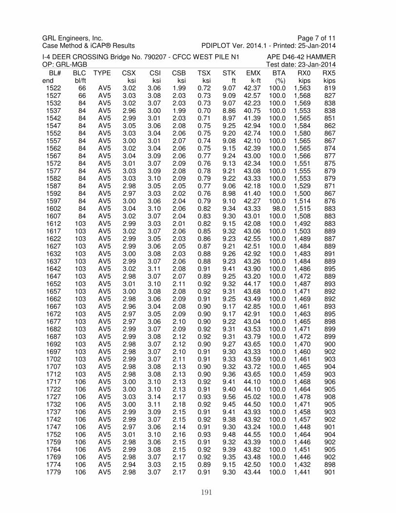
GRL Engineers, Inc.Case Method & iCAP® Results PDIPLOT Ver. 2014.1 - Printed: 25-Jan-2014
I-4 DEER CROSSING Bridge No. 790207 - CFCC WEST PILE N1 APE D46-42 HAMMEROP: GRL-MGB Test date: 23-Jan-2014
BL# BLC TYPE CSX CSI CSB TSX STK EMX BTA RX0 RX5end bl/ft ksi ksi ksi ksi ft k-ft (%) kips kips 1522 66 AV5 3.02 3.06 1.99 0.72 9.07 42.37 100.0 1,563 819 1527 66 AV5 3.03 3.08 2.03 0.73 9.09 42.57 100.0 1,568 827 1532 84 AV5 3.02 3.07 2.03 0.73 9.07 42.23 100.0 1,569 838 1537 84 AV5 2.96 3.00 1.99 0.70 8.86 40.75 100.0 1,553 838 1542 84 AV5 2.99 3.01 2.03 0.71 8.97 41.39 100.0 1,565 851 1547 84 AV5 3.05 3.06 2.08 0.75 9.25 42.94 100.0 1,584 862 1552 84 AV5 3.03 3.04 2.06 0.75 9.20 42.74 100.0 1,580 867 1557 84 AV5 3.00 3.01 2.07 0.74 9.08 42.10 100.0 1,565 867 1562 84 AV5 3.02 3.04 2.06 0.75 9.15 42.39 100.0 1,565 874 1567 84 AV5 3.04 3.09 2.06 0.77 9.24 43.00 100.0 1,566 877 1572 84 AV5 3.01 3.07 2.09 0.76 9.13 42.34 100.0 1,551 875 1577 84 AV5 3.03 3.09 2.08 0.78 9.21 43.08 100.0 1,555 879 1582 84 AV5 3.03 3.10 2.09 0.79 9.22 43.33 100.0 1,553 879 1587 84 AV5 2.98 3.05 2.05 0.77 9.06 42.18 100.0 1,529 871 1592 84 AV5 2.97 3.03 2.02 0.76 8.98 41.40 100.0 1,500 867 1597 84 AV5 3.00 3.06 2.04 0.79 9.10 42.27 100.0 1,514 876 1602 84 AV5 3.04 3.10 2.06 0.82 9.34 43.33 98.0 1,515 883 1607 84 AV5 3.02 3.07 2.04 0.83 9.30 43.01 100.0 1,508 883 1612 103 AV5 2.99 3.03 2.01 0.82 9.15 42.08 100.0 1,492 883 1617 103 AV5 3.02 3.07 2.06 0.85 9.32 43.06 100.0 1,503 889 1622 103 AV5 2.99 3.05 2.03 0.86 9.23 42.55 100.0 1,489 887 1627 103 AV5 2.99 3.06 2.05 0.87 9.21 42.51 100.0 1,484 889 1632 103 AV5 3.00 3.08 2.03 0.88 9.26 42.92 100.0 1,483 891 1637 103 AV5 2.99 3.07 2.06 0.88 9.23 43.26 100.0 1,484 889 1642 103 AV5 3.02 3.11 2.08 0.91 9.41 43.90 100.0 1,486 895 1647 103 AV5 2.98 3.07 2.07 0.89 9.25 43.20 100.0 1,472 889 1652 103 AV5 3.01 3.10 2.11 0.92 9.32 44.17 100.0 1,487 893 1657 103 AV5 3.00 3.08 2.08 0.92 9.31 43.68 100.0 1,471 892 1662 103 AV5 2.98 3.06 2.09 0.91 9.25 43.49 100.0 1,469 892 1667 103 AV5 2.96 3.04 2.08 0.90 9.17 42.85 100.0 1,461 893 1672 103 AV5 2.97 3.05 2.09 0.90 9.17 42.91 100.0 1,463 895 1677 103 AV5 2.97 3.06 2.10 0.90 9.22 43.04 100.0 1,465 898 1682 103 AV5 2.99 3.07 2.09 0.92 9.31 43.53 100.0 1,471 899 1687 103 AV5 2.99 3.08 2.12 0.92 9.31 43.79 100.0 1,472 899 1692 103 AV5 2.98 3.07 2.12 0.90 9.27 43.65 100.0 1,470 900 1697 103 AV5 2.98 3.07 2.10 0.91 9.30 43.33 100.0 1,460 902 1702 103 AV5 2.99 3.07 2.11 0.91 9.33 43.59 100.0 1,461 903 1707 103 AV5 2.98 3.08 2.13 0.90 9.32 43.72 100.0 1,465 904 1712 103 AV5 2.98 3.08 2.13 0.90 9.36 43.65 100.0 1,459 903 1717 106 AV5 3.00 3.10 2.13 0.92 9.41 44.10 100.0 1,468 906 1722 106 AV5 3.00 3.10 2.13 0.91 9.40 44.10 100.0 1,464 905 1727 106 AV5 3.03 3.14 2.17 0.93 9.56 45.02 100.0 1,478 908 1732 106 AV5 3.00 3.11 2.18 0.92 9.45 44.50 100.0 1,471 905 1737 106 AV5 2.99 3.09 2.15 0.91 9.41 43.93 100.0 1,458 903 1742 106 AV5 2.99 3.07 2.15 0.92 9.38 43.92 100.0 1,457 902 1747 106 AV5 2.97 3.06 2.14 0.91 9.30 43.24 100.0 1,448 901 1752 106 AV5 3.01 3.10 2.16 0.93 9.48 44.55 100.0 1,464 904 1759 106 AV5 2.98 3.06 2.15 0.91 9.32 43.39 100.0 1,446 902 1764 106 AV5 2.99 3.08 2.15 0.92 9.39 43.82 100.0 1,451 905 1769 106 AV5 2.98 3.07 2.17 0.92 9.35 43.48 100.0 1,446 902 1774 106 AV5 2.94 3.03 2.15 0.89 9.15 42.50 100.0 1,432 898 1779 106 AV5 2.98 3.07 2.17 0.91 9.30 43.44 100.0 1,441 901
Page 7 of 11
191

GRL Engineers, Inc.Case Method & iCAP® Results PDIPLOT Ver. 2014.1 - Printed: 25-Jan-2014
I-4 DEER CROSSING Bridge No. 790207 - CFCC WEST PILE N1 APE D46-42 HAMMEROP: GRL-MGB Test date: 23-Jan-2014
BL# BLC TYPE CSX CSI CSB TSX STK EMX BTA RX0 RX5end bl/ft ksi ksi ksi ksi ft k-ft (%) kips kips 1784 106 AV5 2.97 3.07 2.18 0.91 9.29 43.30 100.0 1,436 900 1789 106 AV5 3.01 3.11 2.19 0.93 9.40 43.91 100.0 1,445 904 1794 106 AV5 2.99 3.10 2.19 0.93 9.31 43.53 100.0 1,438 902 1799 106 AV5 3.01 3.13 2.21 0.94 9.42 44.29 100.0 1,447 905 1804 106 AV5 3.00 3.11 2.19 0.93 9.33 43.62 100.0 1,434 901 1809 106 AV5 2.99 3.12 2.18 0.93 9.29 43.19 100.0 1,426 899 1814 106 AV5 3.03 3.16 2.22 0.95 9.43 44.41 100.0 1,444 905 1819 106 AV5 3.03 3.16 2.20 0.96 9.40 43.95 100.0 1,432 900 1824 97 AV5 3.03 3.16 2.21 0.96 9.39 44.29 100.0 1,435 899 1829 97 AV5 3.03 3.16 2.21 0.95 9.36 44.12 100.0 1,432 897 1834 97 AV5 3.10 3.23 2.22 0.99 9.62 45.55 100.0 1,440 899 1839 97 AV5 3.08 3.21 2.22 0.99 9.56 45.19 100.0 1,431 892 1844 97 AV5 3.07 3.19 2.20 0.99 9.46 44.59 100.0 1,421 889 1849 97 AV5 3.03 3.15 2.16 0.97 9.25 42.97 100.0 1,394 883 1854 97 AV5 3.09 3.22 2.20 1.00 9.46 44.70 100.0 1,418 889 1859 97 AV5 3.08 3.21 2.19 0.99 9.41 44.17 100.0 1,407 883 1864 97 AV5 3.12 3.25 2.21 1.01 9.49 45.11 100.0 1,421 886 1869 97 AV5 3.13 3.27 2.20 1.02 9.53 45.48 100.0 1,416 881 1874 97 AV5 3.18 3.32 2.21 1.05 9.67 46.47 100.0 1,421 881 1879 97 AV5 3.13 3.26 2.18 1.02 9.47 44.95 100.0 1,401 871 1884 97 AV5 3.14 3.28 2.19 1.03 9.47 45.15 100.0 1,404 871 1889 97 AV5 3.16 3.30 2.17 1.04 9.51 45.09 100.0 1,395 866 1894 97 AV5 3.17 3.31 2.17 1.05 9.52 45.17 100.0 1,397 865 1899 97 AV5 3.17 3.31 2.16 1.05 9.50 44.96 100.0 1,387 860 1904 97 AV5 3.19 3.34 2.17 1.05 9.53 45.57 100.0 1,394 860 1909 97 AV5 3.19 3.34 2.15 1.06 9.49 45.23 100.0 1,381 853 1914 97 AV5 3.22 3.37 2.16 1.08 9.55 45.82 100.0 1,384 850 1919 86 AV5 3.23 3.38 2.14 1.08 9.53 45.72 100.0 1,376 844 1924 86 AV5 3.21 3.36 2.12 1.08 9.42 45.03 100.0 1,363 837 1929 86 AV5 3.21 3.35 2.12 1.07 9.39 44.85 100.0 1,359 833 1934 86 AV5 3.24 3.38 2.12 1.08 9.48 45.14 100.0 1,360 834 1939 86 AV5 3.25 3.40 2.11 1.10 9.48 45.38 100.0 1,362 834 1944 86 AV5 3.28 3.43 2.10 1.12 9.57 45.67 100.0 1,358 829 1949 86 AV5 3.26 3.41 2.09 1.10 9.43 44.94 100.0 1,346 823 1954 86 AV5 3.28 3.42 2.09 1.11 9.45 45.21 100.0 1,345 822 1959 86 AV5 3.30 3.45 2.10 1.13 9.55 46.14 100.0 1,353 821 1964 86 AV5 3.32 3.47 2.09 1.14 9.59 46.13 100.0 1,345 816 1969 86 AV5 3.30 3.45 2.08 1.13 9.49 45.49 100.0 1,336 812 1974 86 AV5 3.28 3.43 2.06 1.13 9.40 44.98 100.0 1,325 806 1979 86 AV5 3.33 3.50 2.08 1.15 9.54 46.05 100.0 1,332 804 1984 86 AV5 3.31 3.48 2.06 1.15 9.47 45.31 100.0 1,320 802 1989 86 AV5 3.33 3.48 2.05 1.15 9.48 45.45 100.0 1,317 800 1994 86 AV5 3.34 3.48 2.06 1.16 9.50 45.95 100.0 1,321 800 1999 86 AV5 3.35 3.49 2.05 1.16 9.54 46.07 100.0 1,317 796 2004 76 AV5 3.36 3.50 2.04 1.16 9.54 45.72 100.0 1,314 792 2009 76 AV5 3.38 3.52 2.04 1.17 9.60 46.16 100.0 1,312 788 2014 76 AV5 3.35 3.49 2.03 1.17 9.47 45.56 100.0 1,308 787 2019 76 AV5 3.38 3.53 2.03 1.18 9.56 46.12 100.0 1,309 786 2024 76 AV5 3.37 3.51 2.02 1.16 9.50 45.77 100.0 1,302 778 2029 76 AV5 3.39 3.53 2.01 1.17 9.55 45.77 100.0 1,295 773 2034 76 AV5 3.39 3.53 2.00 1.17 9.54 45.87 100.0 1,292 771 2039 76 AV5 3.41 3.56 2.00 1.18 9.62 46.24 100.0 1,291 768
Page 8 of 11
192

GRL Engineers, Inc.Case Method & iCAP® Results PDIPLOT Ver. 2014.1 - Printed: 25-Jan-2014
I-4 DEER CROSSING Bridge No. 790207 - CFCC WEST PILE N1 APE D46-42 HAMMEROP: GRL-MGB Test date: 23-Jan-2014
BL# BLC TYPE CSX CSI CSB TSX STK EMX BTA RX0 RX5end bl/ft ksi ksi ksi ksi ft k-ft (%) kips kips 2044 76 AV5 3.40 3.54 1.99 1.18 9.51 45.87 100.0 1,286 766 2049 76 AV5 3.38 3.52 1.97 1.17 9.46 45.21 100.0 1,277 760 2054 76 AV5 3.41 3.56 1.98 1.18 9.56 46.03 100.0 1,280 761 2059 76 AV5 3.44 3.58 1.97 1.19 9.62 46.48 100.0 1,279 755 2064 76 AV5 3.42 3.56 1.96 1.18 9.54 45.98 100.0 1,272 756 2069 76 AV5 3.46 3.61 1.97 1.20 9.73 47.30 100.0 1,282 760 2074 76 AV5 3.38 3.52 1.92 1.17 9.39 44.39 100.0 1,253 738 2079 76 AV5 3.41 3.55 1.94 1.18 9.49 45.43 100.0 1,261 745 2084 69 AV5 3.42 3.56 1.95 1.18 9.51 45.65 100.0 1,268 742 2089 69 AV5 3.41 3.54 1.94 1.18 9.48 45.44 100.0 1,266 743 2094 69 AV5 3.46 3.60 1.97 1.20 9.66 46.71 100.0 1,287 743 2099 69 AV5 3.42 3.55 1.93 1.18 9.51 45.42 100.0 1,266 735 2104 69 AV5 3.44 3.57 1.95 1.18 9.53 45.78 100.0 1,277 732 2109 69 AV5 3.45 3.59 1.95 1.19 9.59 45.78 100.0 1,284 728 2114 69 AV5 3.44 3.58 1.94 1.18 9.52 45.65 100.0 1,276 724 2119 69 AV5 3.45 3.60 1.95 1.19 9.55 45.81 100.0 1,282 723 2124 69 AV5 3.49 3.63 1.98 1.20 9.67 46.59 100.0 1,300 726 2129 69 AV5 3.43 3.57 1.93 1.18 9.47 44.89 100.0 1,272 711 2134 69 AV5 3.47 3.62 1.96 1.19 9.58 46.03 100.0 1,292 717 2139 69 AV5 3.45 3.59 1.94 1.19 9.53 45.10 100.0 1,286 706 2144 69 AV5 3.46 3.58 1.94 1.19 9.54 45.21 100.0 1,294 710 2149 63 AV5 3.47 3.60 1.95 1.19 9.57 45.24 100.0 1,308 706 2154 63 AV5 3.47 3.61 1.95 1.19 9.57 45.29 100.0 1,304 705 2159 63 AV5 3.46 3.60 1.94 1.19 9.55 44.77 100.0 1,303 703 2164 63 AV5 3.48 3.62 1.95 1.20 9.61 45.69 100.0 1,309 702 2169 63 AV5 3.49 3.63 1.96 1.20 9.65 45.85 100.0 1,319 700 2174 63 AV5 3.47 3.61 1.94 1.18 9.56 45.24 100.0 1,309 693 2179 63 AV5 3.44 3.58 1.91 1.17 9.45 44.05 100.0 1,302 689 2184 63 AV5 3.45 3.59 1.91 1.17 9.48 44.32 100.0 1,302 689 2189 63 AV5 3.50 3.65 1.95 1.18 9.66 45.47 100.0 1,326 690 2194 63 AV5 3.46 3.60 1.91 1.16 9.49 44.44 100.0 1,313 687 2199 63 AV5 3.49 3.64 1.94 1.18 9.61 44.97 100.0 1,327 682 2205 63 AV5 3.49 3.64 1.94 1.18 9.61 45.12 100.0 1,328 682 2210 63 AV5 3.46 3.61 1.91 1.17 9.52 44.59 100.0 1,314 678 2215 60 AV5 3.50 3.66 1.93 1.18 9.64 45.65 100.0 1,326 681 2220 60 AV5 3.48 3.65 1.92 1.18 9.60 45.20 100.0 1,315 672 2225 60 AV5 3.45 3.62 1.90 1.17 9.49 44.50 100.0 1,303 671 2230 60 AV5 3.43 3.60 1.87 1.16 9.43 43.95 100.0 1,289 665 2235 60 AV5 3.49 3.69 1.93 1.20 9.65 45.56 100.0 1,324 663 2240 60 AV5 3.51 3.73 1.92 1.21 9.75 46.07 100.0 1,324 659 2245 60 AV5 3.45 3.67 1.87 1.19 9.53 44.83 100.0 1,291 656 2250 60 AV5 3.43 3.66 1.86 1.19 9.47 44.48 100.0 1,286 653 2255 60 AV5 3.48 3.71 1.89 1.22 9.62 45.41 100.0 1,313 653 2260 60 AV5 3.42 3.64 1.83 1.19 9.43 44.04 98.0 1,275 646 2265 60 AV5 3.41 3.62 1.83 1.19 9.41 43.66 100.0 1,276 641 2270 60 AV5 3.40 3.61 1.82 1.20 9.37 43.40 98.0 1,272 637 2275 48 AV5 3.47 3.69 1.87 1.23 9.59 45.30 100.0 1,301 634 2280 48 AV5 3.43 3.65 1.83 1.21 9.52 44.66 100.0 1,279 635 2285 48 AV5 3.39 3.60 1.82 1.20 9.39 43.53 100.0 1,269 624 2290 48 AV5 3.40 3.55 1.82 1.20 9.40 43.36 100.0 1,278 625 2295 48 AV5 3.40 3.51 1.81 1.20 9.36 43.25 100.0 1,274 624 2300 48 AV5 3.41 3.55 1.81 1.20 9.43 43.35 100.0 1,284 627
Page 9 of 11
193

GRL Engineers, Inc.Case Method & iCAP® Results PDIPLOT Ver. 2014.1 - Printed: 25-Jan-2014
I-4 DEER CROSSING Bridge No. 790207 - CFCC WEST PILE N1 APE D46-42 HAMMEROP: GRL-MGB Test date: 23-Jan-2014
BL# BLC TYPE CSX CSI CSB TSX STK EMX BTA RX0 RX5end bl/ft ksi ksi ksi ksi ft k-ft (%) kips kips 2305 48 AV5 3.44 3.59 1.84 1.21 9.55 43.98 100.0 1,310 630 2310 48 AV5 3.46 3.62 1.87 1.21 9.64 44.33 100.0 1,329 627 2315 48 AV5 3.41 3.55 1.81 1.19 9.49 43.44 98.0 1,291 628 2320 51 AV5 3.47 3.61 1.87 1.21 9.74 44.81 100.0 1,328 631 2325 51 AV5 3.41 3.54 1.82 1.19 9.51 43.61 100.0 1,290 623 2330 51 AV5 3.44 3.57 1.85 1.20 9.63 44.33 98.0 1,312 625 2335 51 AV5 3.40 3.54 1.82 1.18 9.52 43.41 96.0 1,299 629 2340 51 AV5 3.38 3.52 1.80 1.17 9.53 43.21 98.0 1,289 624 2345 51 AV5 3.41 3.54 1.82 1.18 9.60 44.09 96.0 1,297 627 2350 51 AV5 3.41 3.57 1.83 1.18 9.70 43.98 100.0 1,312 629 2355 51 AV5 3.34 3.51 1.77 1.16 9.46 42.46 96.0 1,283 622 2360 51 AV5 3.35 3.52 1.77 1.15 9.54 42.81 94.0 1,281 626 2365 51 AV5 3.29 3.46 1.73 1.13 9.34 41.62 94.0 1,252 620 2370 51 AV5 3.34 3.52 1.77 1.14 9.53 42.64 94.0 1,282 629 2375 51 AV5 3.33 3.52 1.76 1.14 9.56 42.69 93.8 1,281 629 2380 51 AV5 3.27 3.44 1.71 1.11 9.35 41.38 89.8 1,251 624 2385 51 AV5 3.32 3.50 1.75 1.13 9.61 42.97 90.0 1,277 626 2390 51 AV5 3.28 3.46 1.72 1.10 9.49 41.97 90.0 1,259 621 2395 51 AV5 3.26 3.44 1.71 1.09 9.44 41.76 89.6 1,254 624 2400 51 AV5 3.25 3.43 1.71 1.08 9.46 41.82 89.6 1,257 623 2405 51 AV5 3.27 3.46 1.71 1.08 9.54 42.50 89.6 1,263 624 2410 51 AV5 3.25 3.44 1.70 1.07 9.56 42.27 89.6 1,264 626 2415 51 AV5 3.29 3.49 1.74 1.08 9.75 43.46 89.6 1,289 629 2420 51 AV5 3.23 3.43 1.69 1.04 9.55 42.10 89.4 1,264 627 2425 51 AV5 3.26 3.45 1.71 1.06 9.71 42.88 89.4 1,277 627 2430 51 AV5 3.17 3.34 1.67 1.02 9.44 41.10 89.6 1,248 619 2435 51 AV5 3.17 3.33 1.68 1.00 9.46 40.95 89.2 1,258 622 2440 51 AV5 3.19 3.36 1.70 1.00 9.59 41.94 89.0 1,270 624 2445 51 AV5 3.17 3.33 1.71 0.98 9.60 41.85 89.2 1,278 627 2450 51 AV5 3.15 3.31 1.71 0.97 9.58 41.46 89.2 1,282 625 2455 51 AV5 3.13 3.29 1.71 0.95 9.53 41.17 89.2 1,283 625 2460 51 AV5 3.15 3.29 1.73 0.95 9.69 41.88 88.6 1,293 629 2465 51 AV5 3.15 3.29 1.75 0.94 9.72 42.08 89.0 1,306 632 2470 51 AV5 3.10 3.25 1.74 0.91 9.60 41.07 88.8 1,308 631 2475 55 AV5 3.12 3.27 1.77 0.90 9.72 41.85 88.6 1,322 633 2480 55 AV5 3.07 3.20 1.76 0.86 9.58 40.44 88.2 1,323 631 2485 55 AV5 3.04 3.18 1.77 0.83 9.50 39.84 88.4 1,326 629 2490 55 AV5 3.02 3.15 1.78 0.79 9.46 39.41 88.2 1,337 634 2495 55 AV5 3.02 3.16 1.80 0.78 9.53 39.91 88.2 1,349 637 2500 55 AV5 3.04 3.17 1.81 0.78 9.62 40.35 88.2 1,359 640 2505 55 AV5 3.04 3.16 1.81 0.76 9.68 40.38 88.4 1,363 643 2510 55 AV5 3.03 3.14 1.82 0.74 9.69 40.44 88.0 1,367 642 2515 55 AV5 3.02 3.11 1.80 0.73 9.63 39.80 88.0 1,361 642 2520 55 AV5 3.03 3.13 1.82 0.71 9.72 40.20 88.4 1,374 647 2525 55 AV5 3.01 3.10 1.82 0.69 9.64 39.84 87.8 1,379 651 2530 58 AV5 3.02 3.11 1.81 0.67 9.75 39.85 87.6 1,384 656 2535 58 AV5 3.04 3.12 1.84 0.67 9.81 40.52 88.0 1,392 654 2540 58 AV5 3.05 3.10 1.83 0.68 9.78 40.20 87.4 1,388 649 2545 58 AV5 3.04 3.10 1.85 0.66 9.75 40.52 88.4 1,388 645 2550 58 AV5 3.07 3.13 1.85 0.66 9.84 41.02 88.0 1,396 645 2555 58 AV5 3.03 3.10 1.82 0.62 9.74 39.16 87.0 1,407 676 2560 58 AV5 3.01 3.07 1.83 0.60 9.70 39.28 87.4 1,396 661
Page 10 of 11
194
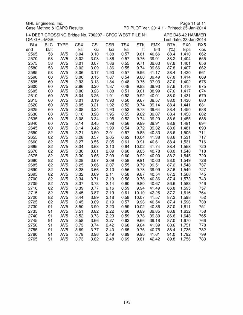
GRL Engineers, Inc.Case Method & iCAP® Results PDIPLOT Ver. 2014.1 - Printed: 25-Jan-2014
I-4 DEER CROSSING Bridge No. 790207 - CFCC WEST PILE N1 APE D46-42 HAMMEROP: GRL-MGB Test date: 23-Jan-2014
BL# BLC TYPE CSX CSI CSB TSX STK EMX BTA RX0 RX5end bl/ft ksi ksi ksi ksi ft k-ft (%) kips kips 2565 58 AV5 3.04 3.10 1.88 0.57 9.81 40.66 88.4 1,410 662 2570 58 AV5 3.02 3.08 1.86 0.57 9.76 39.91 88.2 1,404 655 2575 58 AV5 3.01 3.07 1.86 0.55 9.71 39.63 87.8 1,401 656 2580 58 AV5 3.02 3.09 1.86 0.55 9.74 39.66 87.8 1,407 662 2585 58 AV5 3.06 3.17 1.90 0.57 9.96 41.17 88.4 1,420 661 2590 60 AV5 3.00 3.15 1.87 0.54 9.80 39.49 87.8 1,414 669 2595 60 AV5 2.93 3.13 1.84 0.48 9.75 37.93 87.0 1,402 676 2600 60 AV5 2.96 3.20 1.87 0.48 9.83 38.93 87.6 1,410 675 2605 60 AV5 3.00 3.23 1.88 0.51 9.81 38.99 87.6 1,417 674 2610 60 AV5 3.04 3.26 1.91 0.52 9.92 40.01 88.0 1,431 679 2615 60 AV5 3.01 3.19 1.90 0.50 9.67 38.57 88.0 1,430 680 2620 60 AV5 3.05 3.21 1.92 0.52 9.74 39.14 88.4 1,441 681 2625 60 AV5 3.08 3.24 1.93 0.53 9.78 39.64 88.4 1,450 688 2630 60 AV5 3.10 3.28 1.95 0.55 9.82 39.87 88.4 1,458 682 2635 60 AV5 3.08 3.34 1.95 0.52 9.74 39.29 88.6 1,455 688 2640 60 AV5 3.14 3.45 1.98 0.56 9.89 39.91 88.8 1,481 694 2645 60 AV5 3.14 3.42 1.99 0.54 9.72 39.32 88.6 1,481 693 2650 82 AV5 3.21 3.50 2.01 0.57 9.88 40.33 88.6 1,505 711 2655 82 AV5 3.28 3.57 2.05 0.62 10.04 41.38 88.6 1,531 717 2660 82 AV5 3.27 3.55 2.05 0.61 9.91 40.61 88.4 1,531 716 2665 82 AV5 3.34 3.63 2.10 0.64 10.02 41.74 88.4 1,558 720 2670 82 AV5 3.30 3.61 2.09 0.60 9.85 40.78 88.0 1,548 718 2675 82 AV5 3.30 3.65 2.09 0.60 9.92 40.90 88.2 1,545 720 2680 82 AV5 3.28 3.67 2.09 0.58 9.91 40.60 88.0 1,549 728 2685 82 AV5 3.25 3.66 2.07 0.55 9.79 39.51 87.2 1,548 737 2690 82 AV5 3.28 3.66 2.10 0.56 9.78 39.99 87.6 1,549 727 2695 82 AV5 3.32 3.69 2.11 0.58 9.87 40.54 87.2 1,568 745 2700 82 AV5 3.34 3.71 2.13 0.58 9.76 40.36 87.4 1,573 743 2705 82 AV5 3.37 3.73 2.14 0.60 9.80 40.67 86.6 1,583 746 2710 82 AV5 3.39 3.77 2.16 0.59 9.94 41.49 86.8 1,595 757 2715 82 AV5 3.45 3.87 2.19 0.61 10.10 42.26 87.2 1,616 764 2720 82 AV5 3.44 3.89 2.18 0.58 10.07 41.57 87.2 1,598 752 2725 82 AV5 3.45 3.89 2.19 0.57 9.96 40.54 87.4 1,596 738 2730 91 AV5 3.50 3.90 2.20 0.59 10.02 40.86 87.0 1,611 751 2735 91 AV5 3.51 3.82 2.22 0.60 9.89 39.85 86.8 1,632 758 2740 91 AV5 3.52 3.73 2.23 0.59 9.78 39.30 86.6 1,648 765 2745 91 AV5 3.58 3.66 2.27 0.62 9.66 39.18 87.0 1,670 766 2750 91 AV5 3.73 3.74 2.42 0.68 9.84 41.39 88.6 1,751 778 2755 91 AV5 3.69 3.77 2.40 0.65 9.76 40.75 88.4 1,736 782 2760 91 AV5 3.78 3.96 2.49 0.69 9.90 41.61 91.0 1,792 799 2765 91 AV5 3.73 3.82 2.48 0.69 9.81 42.42 89.8 1,756 783
Page 11 of 11
195

1
1 -
C
HA
NG
E P
ILE
CU
SH
ION
Tes
t dat
e: 2
3-Ja
n-20
14
Max
Cas
e M
etho
d C
apac
ity (
JC=
0.5)
Max
Cas
e M
etho
d C
apac
ity (
JC=
0)
Blo
w C
ount
O.E
. Die
sel H
amm
er S
trok
e
Ten
sion
Str
ess
Max
imum
Max
Mea
sure
d C
ompr
. Str
ess
PD
IPLO
T V
er. 2
014.
1 -
Prin
ted:
25-
Jan-
2014
GR
L E
ngin
eers
, Inc
. - C
ase
Met
hod
& iC
AP
® R
esul
ts
I-4
DE
ER
CR
OS
SIN
G B
ridge
No.
790
207
- C
FC
C W
ES
T P
ILE
N1
0
CS
X (
ksi)
0
TS
X (
ksi)
0
BLC
(bl
ows/
ft)
0
ST
K (
ft)
0
RX
5 (k
ips)
0
RX
0 (k
ips)
0
P e n e t r a t i o n f t
20 40 60 80 100
12
34
36
912
500
1,00
01,
500
2,00
0
12
34
3060
9012
050
01,
000
1,50
02,
000
196

GRL Engineers, Inc.Case Method & iCAP® Results PDIPLOT Ver. 2014.1 - Printed: 25-Jan-2014
I-4 DEER CROSSING Bridge No. 790207 - CFCC WEST PILE N1 APE D46-42 HAMMEROP: GRL-MGB Test date: 23-Jan-2014AR: 576.00 in^2 SP: 0.145 k/ft3LE: 95.00 ft EM: 6,178 ksiWS: 14,050.0 f/s JC: 0.50CSX: Max Measured Compr. StressCSI: Max F1 or F2 Compr. StressCSB: Compression Stress at BottomTSX: Tension Stress MaximumSTK: O.E. Diesel Hammer Stroke
EMX: Max Transferred EnergyBTA: BETA Integrity FactorRX0: Max Case Method Capacity (JC=0)RX5: Max Case Method Capacity (JC=0.5)
BL# depth BLC TYPE CSX CSI CSB TSX STK EMX BTA RX0 RX5end ft bl/ft ksi ksi ksi ksi ft k-ft (%) kips kips
2 23.00 2 AV2 0.96 1.09 0.09 0.69 3.73 12.14 82.0 53 0 4 24.00 2 AV2 0.85 1.04 0.14 0.47 3.06 16.75 80.0 81 0 6 25.00 2 AV2 1.63 1.99 0.34 1.03 7.73 35.07 86.5 197 0
13 26.00 7 AV7 1.70 1.96 0.35 1.14 5.77 20.79 95.7 213 14 25 27.00 12 AV12 1.80 2.07 0.39 1.24 5.77 22.36 100.0 230 63 33 28.00 8 AV8 1.84 2.09 0.43 1.28 5.83 22.09 96.1 254 110 42 29.00 9 AV9 1.90 2.13 0.51 1.27 5.95 23.35 97.3 305 159 52 30.00 10 AV10 1.92 2.16 0.52 1.30 5.98 22.68 100.0 317 165 62 31.00 10 AV10 1.96 2.20 0.54 1.30 6.04 23.24 100.0 331 165 74 32.00 12 AV12 1.97 2.20 0.55 1.28 6.04 22.96 100.0 338 175 86 33.00 12 AV12 2.03 2.25 0.59 1.27 6.17 24.63 100.0 362 183 99 34.00 13 AV13 2.06 2.28 0.63 1.27 6.23 25.16 100.0 386 207
112 35.00 13 AV13 2.13 2.37 0.67 1.29 6.42 26.69 100.0 410 227 127 36.00 15 AV15 2.13 2.40 0.70 1.27 6.42 26.37 100.0 428 251 143 37.00 16 AV16 2.16 2.44 0.74 1.25 6.48 26.78 100.0 452 267 166 38.00 23 AV23 2.11 2.35 0.83 1.21 6.42 25.65 100.0 493 308 187 39.00 21 AV21 2.07 2.33 0.84 1.19 6.25 24.86 100.0 492 310 212 40.00 25 AV25 2.10 2.35 0.90 1.16 6.36 25.21 100.0 527 329 241 41.00 29 AV29 2.18 2.44 0.97 1.15 6.61 26.43 100.0 572 346 266 42.00 25 AV25 2.42 2.69 1.06 1.28 7.43 32.16 100.0 630 373 290 43.00 24 AV24 2.45 2.75 1.10 1.28 7.49 32.95 100.0 647 388 314 44.00 24 AV24 2.42 2.72 1.06 1.25 7.36 32.27 100.0 628 385 335 45.00 21 AV21 2.39 2.71 1.01 1.25 7.31 31.66 100.0 607 382 355 46.00 20 AV20 2.41 2.75 1.02 1.27 7.36 32.18 100.0 607 392 375 47.00 20 AV20 2.41 2.80 1.01 1.26 7.41 32.01 100.0 616 409 396 48.00 21 AV21 2.44 2.83 1.00 1.26 7.52 32.39 100.0 629 426 418 49.00 22 AV22 2.41 2.81 1.01 1.21 7.45 31.65 100.0 633 428 441 50.00 23 AV23 2.43 2.81 1.04 1.20 7.59 32.21 100.0 655 451 465 51.00 24 AV24 2.51 2.88 1.09 1.23 7.90 34.35 100.0 687 479 492 52.00 27 AV27 2.51 2.74 1.12 1.17 8.02 34.20 100.0 721 505 521 53.00 29 AV29 2.59 2.88 1.17 1.21 8.27 36.00 100.0 762 526 549 54.00 28 AV28 2.66 3.13 1.24 1.23 8.63 38.64 100.0 818 541 580 55.00 31 AV29 2.72 3.26 1.66 1.21 8.91 40.39 100.0 1,101 608 611 56.00 31 AV31 2.77 3.14 1.39 1.27 8.79 40.33 100.0 943 586 643 57.00 32 AV32 2.84 3.19 1.41 1.33 8.84 41.22 100.0 948 584 675 58.00 32 AV32 2.88 3.24 1.49 1.35 8.80 41.72 100.0 969 557 705 59.00 30 AV30 2.92 3.19 1.49 1.41 8.79 42.27 100.0 978 540 733 60.00 28 AV28 2.97 3.23 1.51 1.42 8.80 42.64 100.0 1,009 555 762 61.00 29 AV29 3.03 3.28 1.51 1.44 8.85 42.99 100.0 1,062 565 791 62.00 29 AV29 3.07 3.29 1.45 1.45 8.84 42.72 100.0 1,092 553 818 63.00 27 AV27 3.11 3.33 1.43 1.46 8.83 42.87 100.0 1,127 549 848 64.00 30 AV30 3.15 3.37 1.47 1.42 8.85 42.68 100.0 1,183 561 879 65.00 31 AV31 3.23 3.45 1.53 1.41 9.01 43.33 100.0 1,248 589
Page 1 of 2
197

GRL Engineers, Inc.Case Method & iCAP® Results PDIPLOT Ver. 2014.1 - Printed: 25-Jan-2014
I-4 DEER CROSSING Bridge No. 790207 - CFCC WEST PILE N1 APE D46-42 HAMMEROP: GRL-MGB Test date: 23-Jan-2014
BL# depth BLC TYPE CSX CSI CSB TSX STK EMX BTA RX0 RX5end ft bl/ft ksi ksi ksi ksi ft k-ft (%) kips kips
913 66.00 34 AV34 3.26 3.48 1.53 1.36 9.07 43.37 100.0 1,282 604 947 67.00 34 AV34 3.32 3.54 1.56 1.36 9.20 44.11 100.0 1,319 601 981 68.00 34 AV34 3.33 3.62 1.56 1.36 9.23 44.45 100.0 1,305 588
1014 69.00 33 AV33 3.40 3.71 1.59 1.41 9.48 45.82 100.0 1,336 606 1046 70.00 32 AV32 3.38 3.71 1.56 1.40 9.45 45.51 100.0 1,328 589 1081 71.00 35 AV35 3.35 3.68 1.51 1.40 9.40 44.71 100.0 1,323 585 1118 72.00 37 AV37 3.32 3.64 1.49 1.40 9.42 44.51 100.0 1,318 574 1149 73.00 31 AV31 3.24 3.52 1.43 1.33 9.28 43.52 100.0 1,288 529 1186 74.00 37 AV37 3.21 3.43 1.42 1.31 9.41 43.65 100.0 1,293 517 1224 75.00 38 AV38 3.11 3.26 1.39 1.21 9.37 42.51 100.0 1,284 458 1267 76.00 43 AV43 3.02 3.08 1.39 1.09 9.42 41.99 100.0 1,284 411 1310 77.00 43 AV43 2.92 3.25 1.34 0.97 9.48 41.13 100.0 1,269 404 1357 78.00 47 AV47 2.65 2.79 1.25 0.79 8.71 36.35 99.8 1,230 417 1404 79.00 47 AV47 2.96 3.08 1.57 0.90 8.92 41.30 100.0 1,353 427 1461 80.00 57 AV57 3.03 3.14 1.85 0.71 9.05 42.23 98.9 1,510 631 1527 81.00 66 AV66 3.02 3.05 1.96 0.71 9.04 42.20 96.9 1,551 762 1611 82.00 84 AV84 3.01 3.06 2.05 0.77 9.14 42.39 99.9 1,545 869 1714 83.00 103 AV103 2.99 3.07 2.09 0.90 9.28 43.36 100.0 1,474 895 1820 84.00 106 AV104 2.99 3.10 2.17 0.92 9.37 43.81 100.0 1,448 903 1917 85.00 97 AV97 3.13 3.26 2.19 1.02 9.49 44.99 100.0 1,408 876 2003 86.00 86 AV86 3.29 3.44 2.09 1.12 9.49 45.54 100.0 1,341 816 2079 87.00 76 AV76 3.40 3.54 1.99 1.18 9.54 45.86 100.0 1,287 766 2148 88.00 69 AV69 3.45 3.58 1.95 1.19 9.55 45.68 100.0 1,283 725 2211 89.00 63 AV62 3.47 3.61 1.93 1.18 9.56 44.96 100.0 1,312 692 2271 90.00 60 AV60 3.45 3.66 1.88 1.19 9.54 44.74 99.7 1,299 657 2319 91.00 48 AV48 3.43 3.59 1.84 1.21 9.51 44.00 99.8 1,295 628 2370 92.00 51 AV51 3.38 3.53 1.80 1.17 9.54 43.23 96.7 1,290 625 2421 93.00 51 AV51 3.28 3.46 1.72 1.09 9.54 42.32 90.1 1,266 625 2472 94.00 51 AV51 3.16 3.32 1.71 0.97 9.59 41.62 89.1 1,282 626 2527 95.00 55 AV55 3.04 3.15 1.80 0.77 9.62 40.16 88.2 1,353 640 2585 96.00 58 AV58 3.03 3.10 1.85 0.61 9.78 40.12 87.9 1,400 657 2645 97.00 60 AV60 3.04 3.26 1.92 0.52 9.79 39.26 88.1 1,439 682 2727 98.00 82 AV82 3.33 3.70 2.11 0.59 9.92 40.86 87.7 1,564 734 2765 98.42 91 AV38 3.63 3.79 2.34 0.64 9.82 40.60 88.2 1,703 773
Page 2 of 2
198

1
1 -
C
HA
NG
E P
ILE
CU
SH
ION
Tes
t dat
e: 2
3-Ja
n-20
14
Max
Cas
e M
etho
d C
apac
ity (
JC=
0.5)
Max
Cas
e M
etho
d C
apac
ity (
JC=
0)
Blo
w C
ount
O.E
. Die
sel H
amm
er S
trok
e
Ten
sion
Str
ess
Max
imum
Max
Mea
sure
d C
ompr
. Str
ess
PD
IPLO
T V
er. 2
014.
1 -
Prin
ted:
25-
Jan-
2014
GR
L E
ngin
eers
, Inc
. - C
ase
Met
hod
& iC
AP
® R
esul
ts
I-4
DE
ER
CR
OS
SIN
G B
ridge
No.
790
207
- C
FC
C W
ES
T P
ILE
N1
30.0
CS
X (
ksi)
0
TS
X (
ksi)
0
BLC
(bl
ows/
ft)
0
ST
K (
ft)
0
RX
5 (k
ips)
0
RX
0 (k
ips)
0
E l e v a t i o n
20.0
10.0 0.0
-10.
0
-20.
0
-30.
0
-40.
0
-50.
0
12
34
36
912
500
1,00
01,
500
2,00
0
12
34
3060
9012
050
01,
000
1,50
02,
000
199

GRL Engineers, Inc.Case Method & iCAP® Results PDIPLOT Ver. 2014.1 - Printed: 25-Jan-2014
I-4 DEER CROSSING Bridge No. 790207 - CFCC WEST PILE N1 APE D46-42 HAMMEROP: GRL-MGB Test date: 23-Jan-2014AR: 576.00 in^2 SP: 0.145 k/ft3LE: 95.00 ft EM: 6,178 ksiWS: 14,050.0 f/s JC: 0.50CSX: Max Measured Compr. StressCSI: Max F1 or F2 Compr. StressCSB: Compression Stress at BottomTSX: Tension Stress MaximumSTK: O.E. Diesel Hammer Stroke
EMX: Max Transferred EnergyBTA: BETA Integrity FactorRX0: Max Case Method Capacity (JC=0)RX5: Max Case Method Capacity (JC=0.5)
BL# Elev. BLC TYPE CSX CSI CSB TSX STK EMX BTA RX0 RX5end bl/ft ksi ksi ksi ksi ft k-ft (%) kips kips
2 30.4 2 AV2 0.96 1.09 0.09 0.69 3.73 12.14 82.0 53 0 4 29.4 2 AV2 0.85 1.04 0.14 0.47 3.06 16.75 80.0 81 0 6 28.4 2 AV2 1.63 1.99 0.34 1.03 7.73 35.08 86.5 197 0
13 27.4 7 AV7 1.70 1.96 0.35 1.14 5.77 20.79 95.7 213 14 25 26.4 12 AV12 1.80 2.07 0.39 1.24 5.77 22.36 100.0 230 63 33 25.4 8 AV8 1.84 2.09 0.43 1.28 5.83 22.09 96.1 254 110 42 24.4 9 AV9 1.90 2.13 0.51 1.27 5.95 23.35 97.3 305 159 52 23.4 10 AV10 1.92 2.16 0.52 1.30 5.98 22.69 100.0 317 165 62 22.4 10 AV10 1.96 2.20 0.54 1.30 6.04 23.25 100.0 331 165 74 21.4 12 AV12 1.97 2.20 0.55 1.28 6.04 22.97 100.0 338 175 86 20.4 12 AV12 2.03 2.25 0.59 1.27 6.17 24.64 100.0 362 183 99 19.4 13 AV13 2.06 2.28 0.63 1.27 6.23 25.08 100.0 386 208
112 18.4 13 AV13 2.13 2.37 0.67 1.29 6.42 26.69 100.0 410 227 127 17.4 15 AV15 2.13 2.40 0.70 1.27 6.42 26.38 100.0 428 251 143 16.4 16 AV16 2.16 2.44 0.74 1.25 6.48 26.79 100.0 452 267 166 15.4 23 AV23 2.11 2.35 0.83 1.21 6.42 25.66 100.0 493 308 187 14.4 21 AV21 2.07 2.33 0.84 1.19 6.25 24.82 100.0 492 310 212 13.4 25 AV25 2.10 2.35 0.90 1.16 6.36 25.22 100.0 527 329 241 12.4 29 AV29 2.18 2.44 0.97 1.15 6.61 26.44 100.0 572 346 266 11.4 25 AV25 2.42 2.69 1.06 1.28 7.43 32.16 100.0 630 373 290 10.4 24 AV24 2.45 2.75 1.10 1.28 7.49 32.96 100.0 647 388 314 9.4 24 AV24 2.42 2.72 1.06 1.25 7.36 32.27 100.0 628 385 335 8.4 21 AV21 2.39 2.71 1.01 1.25 7.31 31.67 100.0 607 382 355 7.4 20 AV20 2.41 2.75 1.02 1.27 7.36 32.19 100.0 607 392 375 6.4 20 AV20 2.41 2.80 1.01 1.26 7.41 32.02 100.0 616 408 396 5.4 21 AV21 2.44 2.83 1.00 1.26 7.52 32.40 100.0 629 425 418 4.4 22 AV22 2.41 2.81 1.01 1.21 7.45 31.66 100.0 633 428 441 3.4 23 AV23 2.43 2.81 1.04 1.20 7.59 32.22 100.0 655 451 465 2.4 24 AV24 2.51 2.88 1.09 1.23 7.90 34.36 100.0 687 479 492 1.4 27 AV27 2.51 2.74 1.12 1.17 8.02 34.20 100.0 721 505 521 0.4 29 AV29 2.59 2.88 1.17 1.21 8.27 36.00 100.0 762 526 549 -0.6 28 AV28 2.66 3.13 1.24 1.23 8.63 38.62 100.0 818 541 580 -1.6 31 AV29 2.72 3.26 1.66 1.21 8.91 40.39 100.0 1,100 608 611 -2.6 31 AV31 2.77 3.14 1.39 1.27 8.79 40.33 100.0 942 586 643 -3.6 32 AV32 2.84 3.19 1.41 1.33 8.84 41.23 100.0 948 584 675 -4.6 32 AV32 2.88 3.24 1.49 1.35 8.80 41.72 100.0 969 557 705 -5.6 30 AV30 2.92 3.19 1.49 1.41 8.79 42.27 100.0 978 540 733 -6.6 28 AV28 2.97 3.23 1.51 1.42 8.80 42.65 100.0 1,009 555 762 -7.6 29 AV29 3.03 3.28 1.51 1.44 8.85 42.99 100.0 1,062 564 791 -8.6 29 AV29 3.07 3.29 1.45 1.45 8.84 42.72 100.0 1,091 553 818 -9.6 27 AV27 3.11 3.33 1.43 1.46 8.83 42.88 100.0 1,127 549 848 -10.6 30 AV30 3.15 3.37 1.47 1.42 8.85 42.68 100.0 1,183 561 879 -11.6 31 AV31 3.23 3.45 1.53 1.41 9.01 43.32 100.0 1,248 589
Page 1 of 2
200

GRL Engineers, Inc.Case Method & iCAP® Results PDIPLOT Ver. 2014.1 - Printed: 25-Jan-2014
I-4 DEER CROSSING Bridge No. 790207 - CFCC WEST PILE N1 APE D46-42 HAMMEROP: GRL-MGB Test date: 23-Jan-2014
BL# Elev. BLC TYPE CSX CSI CSB TSX STK EMX BTA RX0 RX5end bl/ft ksi ksi ksi ksi ft k-ft (%) kips kips
913 -12.6 34 AV34 3.26 3.48 1.53 1.36 9.07 43.36 100.0 1,281 604 947 -13.6 34 AV34 3.32 3.54 1.56 1.36 9.20 44.10 100.0 1,319 601 981 -14.6 34 AV34 3.33 3.62 1.56 1.36 9.23 44.45 100.0 1,305 588
1014 -15.6 33 AV33 3.40 3.71 1.59 1.41 9.48 45.82 100.0 1,336 606 1046 -16.6 32 AV32 3.38 3.71 1.56 1.40 9.45 45.52 100.0 1,328 589 1081 -17.6 35 AV35 3.35 3.68 1.51 1.40 9.40 44.71 100.0 1,323 585 1118 -18.6 37 AV37 3.32 3.64 1.49 1.40 9.42 44.51 100.0 1,318 574 1149 -19.6 31 AV31 3.24 3.52 1.43 1.33 9.28 43.52 100.0 1,288 529 1186 -20.6 37 AV37 3.21 3.43 1.42 1.31 9.41 43.65 100.0 1,293 517 1224 -21.6 38 AV38 3.11 3.26 1.39 1.21 9.37 42.51 100.0 1,284 458 1267 -22.6 43 AV43 3.02 3.08 1.39 1.09 9.42 41.98 100.0 1,283 411 1310 -23.6 43 AV43 2.92 3.25 1.34 0.97 9.48 41.13 100.0 1,269 404 1357 -24.6 47 AV47 2.65 2.79 1.25 0.79 8.71 36.35 99.8 1,230 417 1404 -25.6 47 AV47 2.96 3.08 1.57 0.90 8.92 41.30 100.0 1,353 427 1461 -26.6 57 AV57 3.03 3.14 1.85 0.71 9.05 42.23 98.9 1,510 631 1527 -27.6 66 AV66 3.02 3.05 1.96 0.71 9.04 42.20 96.9 1,551 762 1611 -28.6 84 AV84 3.01 3.06 2.05 0.77 9.14 42.38 99.9 1,545 869 1714 -29.6 103 AV103 2.99 3.07 2.09 0.90 9.28 43.36 100.0 1,474 895 1820 -30.6 106 AV104 2.99 3.10 2.17 0.92 9.37 43.82 100.0 1,448 902 1917 -31.6 97 AV97 3.13 3.26 2.19 1.02 9.49 45.00 100.0 1,408 876 2003 -32.6 86 AV86 3.29 3.44 2.09 1.12 9.49 45.55 100.0 1,341 816 2079 -33.6 76 AV76 3.40 3.54 1.99 1.18 9.54 45.86 100.0 1,287 766 2148 -34.6 69 AV69 3.45 3.58 1.95 1.19 9.55 45.69 100.0 1,282 725 2211 -35.6 63 AV62 3.47 3.61 1.93 1.18 9.56 44.95 100.0 1,312 692 2271 -36.6 60 AV60 3.45 3.66 1.88 1.19 9.54 44.74 99.7 1,299 657 2319 -37.6 48 AV48 3.43 3.59 1.84 1.21 9.51 43.99 99.8 1,294 628 2370 -38.6 51 AV51 3.38 3.53 1.80 1.17 9.54 43.23 96.7 1,290 625 2421 -39.6 51 AV51 3.28 3.46 1.72 1.09 9.54 42.32 90.1 1,266 625 2472 -40.6 51 AV51 3.16 3.32 1.71 0.97 9.59 41.62 89.1 1,282 626 2527 -41.6 55 AV55 3.04 3.15 1.80 0.77 9.62 40.16 88.2 1,353 640 2585 -42.6 58 AV58 3.03 3.10 1.85 0.61 9.78 40.11 87.9 1,400 657 2645 -43.6 60 AV60 3.04 3.26 1.92 0.52 9.79 39.25 88.1 1,439 682 2727 -44.6 82 AV82 3.33 3.70 2.11 0.59 9.92 40.85 87.7 1,564 734 2765 -45.0 91 AV38 3.63 3.79 2.34 0.64 9.82 40.59 88.2 1,703 773
Page 2 of 2
201

���������� ����� ����������������������������������� � ���!��"�������#
TS: 51.2TB: 17.7
F (3000)V (11.8)
A12 F12
TS: 51.2TB: 17.7
WU (3000)WD (3000)
����������� ��������$��"%�������������������������&�%�� ���!��"�������#�����%�������'��(�)�&&�������"��%�����&�* ���%�� ���!��"�������#�&)#+(,+(-#��(%��%.#��&*�/0��123��#.4
�������������������&��!���+�(�+�$���
56�7(8�8+56,5+�8��+562�9:56
4.�--.;'�--'#;<-�#�.
#�-.-�-(.,�,#,�.--�.-
,;�;-
�����������������=�����*"�=�">�&=*"��=-�=.
8�8�8�8�568�56?@A8B�8B�
(�-4(�,�-�<;#�(,'��-
(.�;(#--�-.-4,#4
������� #%�9 4;<:�4����?-�4<A (%�9��-;:�44�,�?-�4<A�#%�9#44,(:�#-(-��C�+��?#�-(A�(%�9(4-#<:�##.-��C�+��?#�-(A����%��>
D��/��(-#(�##�202

���������� ����� ����������������������������������� � ���!��"�������#
TS: 51.2TB: 17.7
F (3000)V (11.8)
A12 F12
TS: 51.2TB: 17.7
WU (3000)WD (3000)
90 @ 84.60 ft
����������� ��������$��"%�������������������������&�%�� ���!��"�������#�����%�������'��(�)�&&�������"��%�����&�* ���%�� ���!��"�������#�&)#+(,+(-#���%�-%.,��&*�/0��123��(;'#
�������������������&��!���+�(�+�$���
56�7(8�8+56,5+�8��+562�9:56
4.�--.;'�--'#;<-�#�.
#�-.-�-(.,�,#,�;--�.-
4<�,;
�����������������=�����*"�=�">�&=*"��=-�=.
8�8�8�8�568�56?@A8B�8B�
,�;,,�;'(��(-�'44�;<
�(�;-4-�-#;(.;<,
������� #%�9 4;<:�4����?#A (%�9��-;:�44�,�?#A�#%�9#44,(:�#-(-��C�+��?#A�(%�9(4-#<:�##.-��C�+��?#A����%��>
D��/��(-#(�##�
203

204

205

206

207

1
1 -
Cha
nge
Pile
Cus
hion
Tes
t dat
e: 2
4-Ja
n-20
14
Max
Cas
e M
etho
d C
apac
ity (
JC=
0.5)
Max
Cas
e M
etho
d C
apac
ity (
JC=
0)
Blo
w C
ount
O.E
. Die
sel H
amm
er S
trok
e
Ten
sion
Str
ess
Max
imum
Max
Mea
sure
d C
ompr
. Str
ess
PD
IPLO
T V
er. 2
014.
1 -
Prin
ted:
25-
Jan-
2014
GR
L E
ngin
eers
, Inc
. - C
ase
Met
hod
& iC
AP
® R
esul
ts
I-4
DE
ER
CR
OS
SIN
G B
ridge
No.
790
207
- C
FC
C E
AS
T P
ILE
N2
0
CS
X (
ksi)
0
TS
X (
ksi)
0
BLC
(bl
ows/
ft)
0
ST
K (
ft)
0
RX
5 (k
ips)
0
RX
0 (k
ips)
0
B l o w N u m b e r
500
1,00
0
1,50
0
2,00
0
2,50
0
3,00
0
3,50
0
2
2 -
Cha
nge
Pile
Cus
hion
3
3 -
Cha
nge
Pile
Cus
hion
24
68
36
912
600
1,20
01,
800
2,40
0
12
34
3060
9012
060
01,
200
1,80
02,
400
208

GRL Engineers, Inc.Case Method & iCAP® Results PDIPLOT Ver. 2014.1 - Printed: 25-Jan-2014
I-4 DEER CROSSING Bridge No. 790207 - CFCC EAST PILE N2 APE D46-42 HAMMEROP: GRL-MGB Test date: 24-Jan-2014AR: 576.00 in^2 SP: 0.145 k/ft3LE: 95.00 ft EM: 6,178 ksiWS: 14,050.0 f/s JC: 0.50CSX: Max Measured Compr. StressCSI: Max F1 or F2 Compr. StressCSB: Compression Stress at BottomTSX: Tension Stress MaximumSTK: O.E. Diesel Hammer Stroke
EMX: Max Transferred EnergyBTA: BETA Integrity FactorRX0: Max Case Method Capacity (JC=0)RX5: Max Case Method Capacity (JC=0.5)
BL# BLC TYPE CSX CSI CSB TSX STK EMX BTA RX0 RX5end bl/ft ksi ksi ksi ksi ft k-ft (%) kips kips
5 5 AV5 1.71 2.11 0.54 1.07 7.08 29.37 97.6 314 21 10 5 AV5 2.07 2.58 0.70 1.33 6.33 28.75 100.0 408 109 15 10 AV5 2.09 2.54 0.73 1.33 6.02 25.99 100.0 430 167 20 10 AV5 2.09 2.49 0.76 1.32 5.95 25.26 100.0 446 190 25 10 AV5 2.29 2.73 0.90 1.40 6.71 31.50 100.0 530 264 30 10 AV5 2.39 2.82 0.99 1.43 6.93 32.93 100.0 582 300 35 11 AV5 2.50 2.96 1.10 1.45 7.28 35.18 100.0 646 360 40 11 AV5 2.62 3.09 1.20 1.47 7.64 37.73 100.0 708 431 45 12 AV5 2.72 3.23 1.33 1.49 7.94 39.60 100.0 781 500 50 12 AV5 2.77 3.31 1.37 1.49 8.00 39.83 100.0 808 525 55 13 AV5 2.81 3.34 1.42 1.48 8.05 40.66 100.0 839 552 60 13 AV5 2.79 3.30 1.42 1.47 7.86 39.37 100.0 836 540 67 14 AV5 2.87 3.42 1.51 1.50 8.11 40.85 100.0 886 584 72 14 AV5 2.88 3.41 1.50 1.50 8.13 40.92 100.0 881 603 77 14 AV5 2.87 3.38 1.48 1.50 8.06 40.13 100.0 875 596 82 15 AV5 2.91 3.42 1.51 1.50 8.16 40.81 100.0 890 612 87 15 AV5 2.93 3.45 1.52 1.50 8.24 41.40 100.0 895 638 92 15 AV5 2.92 3.45 1.52 1.49 8.19 41.08 100.0 895 630 97 16 AV5 2.97 3.51 1.51 1.51 8.32 41.80 100.0 891 564
102 16 AV5 2.99 3.55 1.53 1.50 8.40 42.21 100.0 903 578 107 16 AV5 2.97 3.54 1.51 1.48 8.32 41.34 100.0 890 567 112 19 AV5 2.98 3.57 1.52 1.48 8.34 41.29 100.0 899 550 117 19 AV5 3.02 3.63 1.57 1.48 8.49 42.32 100.0 926 568 122 19 AV5 2.99 3.60 1.55 1.45 8.36 41.79 100.0 912 546 127 19 AV5 2.96 3.52 1.52 1.44 8.28 41.31 100.0 897 533 133 19 AV5 3.03 3.58 1.58 1.46 8.50 42.35 100.0 930 559 138 19 AV5 3.01 3.57 1.57 1.45 8.45 42.04 100.0 923 541 143 19 AV5 3.01 3.58 1.55 1.44 8.45 41.98 100.0 917 538 148 19 AV5 3.03 3.60 1.58 1.44 8.51 42.19 100.0 934 525 153 23 AV5 2.97 3.53 1.53 1.42 8.29 40.38 100.0 906 483 158 23 AV5 2.99 3.57 1.55 1.42 8.38 40.70 100.0 918 489 163 23 AV5 3.02 3.62 1.57 1.42 8.48 41.35 100.0 927 488 168 23 AV5 2.98 3.57 1.54 1.40 8.32 40.65 100.0 909 476 173 24 AV5 2.99 3.59 1.56 1.41 8.39 40.70 100.0 922 480 178 24 AV5 3.03 3.63 1.59 1.42 8.55 41.63 100.0 944 491 183 24 AV5 2.98 3.58 1.54 1.40 8.39 40.76 100.0 911 479 188 24 AV5 3.07 3.69 1.62 1.42 8.71 42.80 100.0 958 496 193 24 AV5 3.04 3.66 1.59 1.41 8.59 41.86 100.0 944 481 199 25 AV5 3.01 3.64 1.57 1.39 8.46 41.06 100.0 928 472 204 25 AV5 3.06 3.69 1.61 1.41 8.67 41.99 100.0 956 478 209 25 AV5 3.06 3.71 1.60 1.39 8.70 42.53 100.0 947 497 214 25 AV5 3.07 3.73 1.62 1.39 8.73 42.64 100.0 961 487 219 25 AV5 3.05 3.70 1.59 1.38 8.63 42.00 100.0 939 476
Page 1 of 13
209

GRL Engineers, Inc.Case Method & iCAP® Results PDIPLOT Ver. 2014.1 - Printed: 25-Jan-2014
I-4 DEER CROSSING Bridge No. 790207 - CFCC EAST PILE N2 APE D46-42 HAMMEROP: GRL-MGB Test date: 24-Jan-2014
BL# BLC TYPE CSX CSI CSB TSX STK EMX BTA RX0 RX5end bl/ft ksi ksi ksi ksi ft k-ft (%) kips kips
224 25 AV5 3.05 3.70 1.61 1.38 8.66 41.92 100.0 951 479 229 25 AV5 3.10 3.77 1.66 1.40 8.86 43.45 100.0 979 493 234 25 AV5 3.05 3.72 1.60 1.38 8.70 42.33 100.0 949 484 239 25 AV5 3.07 3.75 1.63 1.39 8.80 42.52 100.0 962 491 244 25 AV5 3.10 3.79 1.64 1.38 8.92 43.31 100.0 970 499 249 26 AV5 3.11 3.79 1.66 1.39 8.95 43.49 100.0 985 498 254 26 AV5 3.07 3.77 1.61 1.37 8.77 42.68 100.0 953 493 259 26 AV5 3.10 3.82 1.63 1.39 8.91 43.55 100.0 965 511 265 26 AV5 3.00 3.70 1.55 1.37 8.54 40.80 100.0 917 492 270 26 AV5 2.97 3.67 1.52 1.36 8.48 40.32 100.0 904 495 275 24 AV5 3.07 3.79 1.60 1.38 8.79 42.53 100.0 949 497 280 24 AV5 3.07 3.79 1.61 1.38 8.87 42.97 100.0 955 499 285 24 AV5 3.04 3.74 1.59 1.39 8.72 41.91 100.0 941 492 290 24 AV5 3.00 3.71 1.55 1.38 8.58 41.06 100.0 919 490 295 24 AV5 3.05 3.76 1.58 1.38 8.71 42.35 100.0 937 496 300 23 AV5 2.98 3.68 1.52 1.38 8.49 40.41 100.0 903 491 305 23 AV5 3.06 3.78 1.57 1.38 8.74 42.33 100.0 930 493 310 23 AV5 3.01 3.72 1.55 1.38 8.60 41.23 100.0 921 492 315 23 AV5 3.09 3.84 1.60 1.37 8.83 43.20 100.0 949 499 320 20 AV5 3.05 3.79 1.58 1.38 8.72 42.16 100.0 940 498 325 20 AV5 2.94 3.64 1.49 1.37 8.30 39.67 100.0 889 503 331 20 AV5 3.05 3.76 1.58 1.38 8.65 42.23 100.0 937 509 336 20 AV5 3.12 3.82 1.62 1.40 8.90 43.72 100.0 962 516 341 20 AV5 3.12 3.82 1.63 1.40 8.90 43.99 100.0 970 516 346 20 AV5 3.12 3.82 1.61 1.41 8.92 43.71 100.0 963 518 351 20 AV5 3.11 3.80 1.62 1.41 8.82 43.13 100.0 965 505 356 20 AV5 3.15 3.85 1.63 1.40 8.99 44.11 100.0 970 513 361 22 AV5 3.14 3.85 1.63 1.40 8.95 43.58 100.0 970 511 366 22 AV5 3.12 3.81 1.62 1.39 8.83 42.77 100.0 969 513 371 22 AV5 3.14 3.83 1.63 1.38 8.90 43.39 100.0 973 521 376 22 AV5 3.16 3.85 1.65 1.39 8.93 43.39 100.0 991 529 381 22 AV5 3.15 3.83 1.64 1.39 8.87 42.83 100.0 989 544 386 28 AV5 3.19 3.89 1.67 1.39 9.01 43.18 100.0 1,022 566 391 28 AV5 3.18 3.88 1.68 1.39 8.97 42.84 100.0 1,024 576 397 28 AV5 3.15 3.84 1.62 1.37 8.82 42.13 100.0 998 584 402 28 AV5 3.23 3.93 1.67 1.39 9.12 44.07 100.0 1,035 594 407 28 AV5 3.21 3.90 1.68 1.38 8.98 43.18 100.0 1,042 597 412 21 AV5 3.25 3.96 1.69 1.39 9.13 44.45 100.0 1,048 601 417 21 AV5 3.25 3.96 1.69 1.38 9.08 44.39 100.0 1,049 604 422 21 AV5 3.25 3.97 1.70 1.39 9.06 44.02 100.0 1,057 607 427 21 AV5 3.29 4.02 1.70 1.38 9.16 45.05 100.0 1,065 616 432 28 AV5 3.27 4.00 1.70 1.37 9.09 44.32 100.0 1,069 625 437 28 AV5 3.25 3.97 1.70 1.36 8.95 43.75 100.0 1,071 636 442 28 AV5 3.33 4.06 1.72 1.37 9.20 45.15 100.0 1,092 644 447 28 AV5 3.33 4.06 1.74 1.37 9.19 45.21 100.0 1,104 650 452 28 AV5 3.31 4.04 1.74 1.37 9.07 44.43 100.0 1,108 648 457 28 AV5 3.33 4.07 1.74 1.36 9.09 44.89 100.0 1,108 658 463 31 AV5 3.39 4.13 1.79 1.37 9.31 46.16 100.0 1,140 666 468 31 AV5 3.35 4.08 1.76 1.36 9.12 44.79 100.0 1,122 664 473 31 AV5 3.38 4.12 1.78 1.36 9.22 45.76 100.0 1,132 674 478 31 AV5 3.38 4.11 1.77 1.36 9.18 45.35 100.0 1,127 674 483 31 AV5 3.38 4.11 1.77 1.35 9.16 45.25 100.0 1,134 680
Page 2 of 13
210

GRL Engineers, Inc.Case Method & iCAP® Results PDIPLOT Ver. 2014.1 - Printed: 25-Jan-2014
I-4 DEER CROSSING Bridge No. 790207 - CFCC EAST PILE N2 APE D46-42 HAMMEROP: GRL-MGB Test date: 24-Jan-2014
BL# BLC TYPE CSX CSI CSB TSX STK EMX BTA RX0 RX5end bl/ft ksi ksi ksi ksi ft k-ft (%) kips kips
488 31 AV5 3.46 4.20 1.82 1.34 9.44 46.77 100.0 1,160 688 493 35 AV5 3.42 4.14 1.79 1.33 9.27 45.47 100.0 1,147 686 498 35 AV5 3.33 4.03 1.73 1.32 8.91 42.94 100.0 1,115 681 503 35 AV5 3.46 4.17 1.84 1.34 9.34 46.02 100.0 1,182 695 508 35 AV5 3.46 4.15 1.84 1.34 9.30 45.80 100.0 1,183 692 513 35 AV5 3.31 3.96 1.73 1.31 8.75 42.42 100.0 1,116 688 518 35 AV5 3.53 4.21 1.88 1.33 9.41 47.09 100.0 1,216 703 523 35 AV5 3.58 4.28 1.90 1.31 9.39 47.48 100.0 1,230 710 529 34 AV5 3.54 4.23 1.88 1.30 9.24 46.46 100.0 1,219 711 534 34 AV5 3.59 4.26 1.91 1.31 9.36 47.19 100.0 1,243 709 539 34 AV5 3.38 4.03 1.87 1.20 9.36 41.73 100.0 1,229 669 544 34 AV5 3.72 4.40 2.16 1.33 9.33 48.14 100.0 1,385 711 549 34 AV5 3.72 4.40 2.15 1.32 9.33 48.01 100.0 1,383 716 554 34 AV5 3.72 4.39 2.12 1.32 9.30 48.25 100.0 1,379 725 559 35 AV5 3.74 4.41 2.16 1.32 9.35 48.38 100.0 1,402 726 564 35 AV5 3.74 4.41 2.15 1.32 9.34 48.56 100.0 1,398 731 569 35 AV5 3.73 4.39 2.12 1.32 9.29 48.02 100.0 1,389 727 574 35 AV5 3.71 4.36 2.11 1.32 9.26 47.46 100.0 1,389 731 579 35 AV5 3.79 4.44 2.19 1.32 9.52 49.61 100.0 1,432 745 584 35 AV5 3.70 4.34 2.09 1.31 9.26 47.73 100.0 1,383 736 589 35 AV5 3.70 4.33 2.08 1.31 9.28 47.54 100.0 1,377 740 595 39 AV5 3.73 4.36 2.12 1.30 9.39 48.41 100.0 1,399 750 600 39 AV5 3.76 4.40 2.13 1.31 9.49 49.02 100.0 1,412 755 605 39 AV5 3.73 4.36 2.09 1.30 9.39 48.36 100.0 1,391 756 610 39 AV5 3.72 4.35 2.10 1.30 9.35 48.22 100.0 1,394 753 615 39 AV5 3.70 4.33 2.10 1.30 9.32 47.77 100.0 1,387 748 620 39 AV5 3.69 4.31 2.08 1.30 9.27 47.41 100.0 1,377 745 625 39 AV5 3.74 4.37 2.11 1.30 9.43 48.85 100.0 1,393 748 630 39 AV5 3.75 4.37 2.14 1.30 9.49 49.02 100.0 1,408 740 635 40 AV5 3.70 4.30 2.09 1.30 9.32 47.84 100.0 1,379 730 640 40 AV5 3.73 4.34 2.11 1.30 9.42 48.60 100.0 1,390 735 645 40 AV5 3.73 4.34 2.13 1.30 9.44 48.69 100.0 1,400 727 650 40 AV5 3.71 4.31 2.13 1.30 9.36 48.36 100.0 1,396 729 655 40 AV5 3.82 4.45 2.18 1.31 9.69 50.70 100.0 1,431 723 661 40 AV5 3.74 4.36 2.15 1.31 9.44 48.80 100.0 1,409 711 666 40 AV5 3.71 4.33 2.11 1.30 9.32 48.08 100.0 1,389 715 671 40 AV5 3.76 4.41 2.13 1.31 9.46 49.42 100.0 1,409 717 676 39 AV5 3.73 4.38 2.10 1.31 9.37 48.79 100.0 1,395 708 681 39 AV5 3.77 4.43 2.12 1.32 9.46 49.46 100.0 1,420 699 686 39 AV5 3.71 4.36 2.08 1.31 9.26 47.85 100.0 1,395 695 691 39 AV5 3.71 4.36 2.08 1.31 9.23 47.85 100.0 1,394 688 696 39 AV5 3.72 4.36 2.07 1.31 9.26 47.99 100.0 1,390 698 701 39 AV5 3.73 4.36 2.10 1.30 9.33 48.47 100.0 1,405 710 706 39 AV5 3.72 4.34 2.08 1.30 9.26 48.21 100.0 1,396 708 711 39 AV5 3.76 4.37 2.11 1.31 9.38 48.95 100.0 1,418 706 716 40 AV5 3.66 4.26 2.03 1.30 9.09 46.64 100.0 1,373 705 721 40 AV5 3.73 4.33 2.06 1.30 9.30 48.42 100.0 1,401 714 727 40 AV5 3.76 4.36 2.08 1.30 9.39 49.14 100.0 1,414 721 732 40 AV5 3.73 4.31 2.04 1.30 9.31 48.40 100.0 1,395 719 737 40 AV5 3.75 4.33 2.08 1.30 9.37 48.51 100.0 1,420 720 742 40 AV5 3.72 4.30 2.06 1.30 9.30 47.93 100.0 1,405 717 747 40 AV5 3.73 4.33 2.06 1.29 9.35 48.42 100.0 1,413 718
Page 3 of 13
211

GRL Engineers, Inc.Case Method & iCAP® Results PDIPLOT Ver. 2014.1 - Printed: 25-Jan-2014
I-4 DEER CROSSING Bridge No. 790207 - CFCC EAST PILE N2 APE D46-42 HAMMEROP: GRL-MGB Test date: 24-Jan-2014
BL# BLC TYPE CSX CSI CSB TSX STK EMX BTA RX0 RX5end bl/ft ksi ksi ksi ksi ft k-ft (%) kips kips
752 37 AV5 3.71 4.32 2.06 1.29 9.31 48.06 100.0 1,414 719 757 37 AV5 3.68 4.28 2.01 1.29 9.23 47.44 100.0 1,386 713 762 37 AV5 3.73 4.32 2.05 1.29 9.41 48.64 100.0 1,412 718 767 37 AV5 3.72 4.29 2.03 1.29 9.36 48.45 100.0 1,401 716 772 37 AV5 3.69 4.25 2.01 1.29 9.32 47.53 100.0 1,398 708 777 37 AV5 3.75 4.32 2.04 1.29 9.52 49.03 100.0 1,419 715 782 37 AV5 3.65 4.22 1.95 1.29 9.22 46.72 100.0 1,369 698 787 37 AV5 3.69 4.26 1.98 1.29 9.33 47.78 100.0 1,391 706 793 35 AV5 3.69 4.27 1.98 1.29 9.37 47.88 100.0 1,392 699 798 35 AV5 3.65 4.21 1.94 1.28 9.22 46.87 100.0 1,375 696 803 35 AV5 3.68 4.25 1.96 1.28 9.37 47.93 100.0 1,388 694 808 35 AV5 3.64 4.20 1.93 1.27 9.24 46.88 100.0 1,374 695 813 35 AV5 3.67 4.23 1.93 1.27 9.34 47.66 100.0 1,382 698 818 35 AV5 3.68 4.25 1.93 1.27 9.36 47.74 100.0 1,387 696 823 35 AV5 3.63 4.20 1.92 1.26 9.23 46.90 100.0 1,383 690 828 35 AV5 3.61 4.17 1.89 1.26 9.15 46.02 100.0 1,375 685 833 35 AV5 3.63 4.20 1.88 1.26 9.24 46.12 100.0 1,379 699 838 35 AV5 3.63 4.20 1.87 1.26 9.28 46.24 100.0 1,387 707 843 35 AV5 3.57 4.14 1.83 1.25 9.16 45.38 100.0 1,353 697 848 35 AV5 3.55 4.12 1.79 1.24 9.09 45.15 100.0 1,341 698 853 35 AV5 3.56 4.15 1.80 1.24 9.13 45.42 100.0 1,352 702 859 34 AV5 3.57 4.18 1.81 1.24 9.25 46.24 100.0 1,358 708 864 34 AV5 3.55 4.16 1.74 1.24 9.26 45.92 100.0 1,334 708 869 34 AV5 3.53 4.12 1.71 1.23 9.20 45.30 100.0 1,327 704 874 34 AV5 3.50 4.06 1.67 1.22 9.14 44.69 100.0 1,306 707 879 34 AV5 3.56 4.14 1.71 1.24 9.40 46.24 100.0 1,347 719 884 34 AV5 3.47 4.04 1.65 1.22 9.12 44.29 100.0 1,309 702 889 34 AV5 3.48 4.02 1.63 1.22 9.17 44.48 100.0 1,304 704 894 37 AV5 3.45 3.97 1.61 1.21 9.09 43.75 100.0 1,300 701 899 37 AV5 3.45 3.96 1.62 1.22 9.19 43.63 100.0 1,317 703 904 37 AV5 3.45 3.94 1.59 1.21 9.20 43.86 100.0 1,307 706 909 37 AV5 3.40 3.86 1.51 1.18 9.12 42.84 100.0 1,275 700 914 37 AV5 3.40 3.79 1.54 1.19 9.18 42.88 100.0 1,294 701 919 37 AV5 3.36 3.71 1.51 1.17 9.10 42.10 100.0 1,285 691 925 37 AV5 3.37 3.68 1.51 1.18 9.21 42.56 100.0 1,286 700 930 37 AV5 3.34 3.62 1.51 1.17 9.21 42.40 100.0 1,285 694 935 37 AV5 3.33 3.58 1.46 1.17 9.21 42.40 100.0 1,269 693 940 37 AV5 3.30 3.54 1.44 1.16 9.16 41.59 100.0 1,263 688 945 37 AV5 3.30 3.51 1.44 1.16 9.19 41.89 100.0 1,269 690 950 37 AV5 3.30 3.49 1.42 1.17 9.21 41.77 100.0 1,259 685 955 37 AV5 3.32 3.48 1.43 1.17 9.31 42.23 100.0 1,271 690 960 37 AV5 3.29 3.43 1.39 1.18 9.25 41.53 100.0 1,259 680 965 37 AV5 3.30 3.43 1.41 1.18 9.31 42.17 100.0 1,267 688 970 47 AV5 3.30 3.43 1.38 1.18 9.30 41.83 100.0 1,262 693 975 47 AV5 3.35 3.47 1.42 1.21 9.52 42.89 100.0 1,288 705 980 47 AV5 3.34 3.44 1.41 1.21 9.48 42.13 100.0 1,289 700 985 47 AV5 3.28 3.32 1.39 1.18 9.38 41.38 100.0 1,276 688 991 47 AV5 3.29 3.33 1.34 1.18 9.42 41.46 100.0 1,257 691 996 47 AV5 3.27 3.33 1.37 1.18 9.39 40.94 100.0 1,270 682
1001 47 AV5 3.24 3.32 1.38 1.15 9.28 40.00 100.0 1,278 674 1006 47 AV5 3.27 3.41 1.41 1.17 9.42 40.79 100.0 1,304 683 1011 47 AV5 3.30 3.43 1.40 1.15 9.48 41.17 100.0 1,305 686
Page 4 of 13
212

GRL Engineers, Inc.Case Method & iCAP® Results PDIPLOT Ver. 2014.1 - Printed: 25-Jan-2014
I-4 DEER CROSSING Bridge No. 790207 - CFCC EAST PILE N2 APE D46-42 HAMMEROP: GRL-MGB Test date: 24-Jan-2014
BL# BLC TYPE CSX CSI CSB TSX STK EMX BTA RX0 RX5end bl/ft ksi ksi ksi ksi ft k-ft (%) kips kips 1016 25 AV5 3.32 3.45 1.45 1.16 9.52 41.67 100.0 1,322 675 1021 25 AV5 3.30 3.44 1.43 1.15 9.43 41.34 100.0 1,309 662 1026 25 AV5 3.33 3.47 1.47 1.15 9.50 41.91 100.0 1,328 663 1031 25 AV5 3.33 3.49 1.46 1.15 9.48 41.63 100.0 1,333 663 1036 25 AV5 3.34 3.48 1.50 1.15 9.53 42.05 100.0 1,347 663 1041 36 AV5 3.35 3.42 1.46 1.14 9.55 41.86 100.0 1,330 665 1046 36 AV5 3.34 3.40 1.46 1.13 9.46 41.12 100.0 1,334 659 1051 36 AV5 3.35 3.51 1.42 1.13 9.50 41.46 100.0 1,321 664 1056 36 AV5 3.42 3.60 1.52 1.18 9.57 41.88 100.0 1,363 666 1061 36 AV5 3.47 3.63 1.56 1.19 9.54 42.32 100.0 1,387 669 1066 36 AV5 3.52 3.65 1.65 1.20 9.55 42.72 100.0 1,421 672 1071 36 AV5 3.50 3.58 1.64 1.16 9.48 42.51 100.0 1,416 668 1076 33 AV5 3.62 3.75 1.78 1.18 9.53 43.46 100.0 1,480 677 1081 33 AV5 3.71 3.86 1.92 1.20 9.56 44.44 100.0 1,537 672 1086 33 AV5 3.76 3.95 2.02 1.20 9.60 44.91 100.0 1,582 668 1091 33 AV5 3.75 3.94 2.00 1.19 9.47 44.28 100.0 1,574 656 1096 33 AV5 3.83 3.98 2.04 1.20 9.70 45.64 100.0 1,610 664 1101 33 AV5 3.81 3.92 2.03 1.19 9.59 45.30 100.0 1,602 660 1106 33 AV5 3.76 3.83 1.97 1.19 9.48 44.57 100.0 1,576 656 1111 39 AV5 3.77 3.83 2.02 1.19 9.58 44.80 100.0 1,596 658 1116 39 AV5 3.72 3.82 1.98 1.18 9.51 44.11 100.0 1,578 656 1121 39 AV5 3.71 3.82 1.97 1.16 9.51 44.59 100.0 1,563 658 1126 39 AV5 2.14 2.45 1.00 0.38 8.64 28.66 100.0 1,124 620 1131 39 AV5 3.12 3.57 1.32 0.97 9.04 42.51 100.0 1,334 503 1136 39 AV5 3.46 3.88 1.48 1.16 9.16 45.61 100.0 1,414 558 1141 39 AV5 3.49 3.91 1.53 1.20 8.89 44.57 100.0 1,425 554 1146 39 AV5 3.58 4.00 1.62 1.27 9.12 46.51 100.0 1,449 585 1151 35 AV5 3.58 4.00 1.64 1.28 8.97 45.79 100.0 1,446 578 1156 35 AV5 3.68 4.10 1.69 1.32 9.28 48.15 100.0 1,481 608 1161 35 AV5 3.63 4.06 1.64 1.30 9.01 46.27 100.0 1,451 591 1166 35 AV5 3.75 4.21 1.73 1.36 9.45 49.41 100.0 1,501 624 1171 35 AV5 3.70 4.17 1.69 1.34 9.20 47.76 100.0 1,474 609 1176 35 AV5 3.69 4.18 1.68 1.33 9.12 47.42 100.0 1,474 613 1181 35 AV5 3.77 4.30 1.73 1.38 9.45 49.44 100.0 1,496 641 1186 37 AV5 3.76 4.31 1.71 1.36 9.37 48.86 100.0 1,501 637 1191 37 AV5 3.72 4.27 1.64 1.35 9.19 47.89 100.0 1,475 634 1196 37 AV5 3.76 4.33 1.68 1.38 9.34 48.66 100.0 1,488 655 1201 37 AV5 3.75 4.33 1.68 1.40 9.31 48.25 100.0 1,480 659 1206 37 AV5 3.66 4.24 1.62 1.35 9.02 46.48 100.0 1,449 643 1211 37 AV5 3.73 4.32 1.69 1.41 9.23 47.83 100.0 1,481 664 1216 37 AV5 3.68 4.26 1.66 1.38 9.10 46.74 100.0 1,458 650 1221 37 AV5 3.66 4.24 1.62 1.36 8.97 46.19 100.0 1,434 641 1226 37 AV5 3.70 4.29 1.69 1.40 9.18 47.17 100.0 1,467 654 1231 37 AV5 3.67 4.26 1.66 1.37 9.08 46.57 100.0 1,448 641 1236 37 AV5 3.75 4.36 1.73 1.42 9.37 48.40 100.0 1,476 661 1241 37 AV5 3.66 4.27 1.67 1.36 9.09 46.44 100.0 1,444 631 1246 37 AV5 3.68 4.27 1.72 1.37 9.12 46.70 100.0 1,452 640 1251 37 AV5 3.71 4.25 1.69 1.39 9.22 47.18 100.0 1,449 644 1256 36 AV5 3.66 4.16 1.70 1.37 9.09 46.29 100.0 1,441 624 1261 36 AV5 3.61 4.08 1.64 1.34 8.95 45.27 100.0 1,417 607 1266 36 AV5 3.65 4.10 1.71 1.36 9.08 45.97 100.0 1,442 611 1271 36 AV5 3.59 4.02 1.66 1.33 8.93 44.84 100.0 1,408 591
Page 5 of 13
213

GRL Engineers, Inc.Case Method & iCAP® Results PDIPLOT Ver. 2014.1 - Printed: 25-Jan-2014
I-4 DEER CROSSING Bridge No. 790207 - CFCC EAST PILE N2 APE D46-42 HAMMEROP: GRL-MGB Test date: 24-Jan-2014
BL# BLC TYPE CSX CSI CSB TSX STK EMX BTA RX0 RX5end bl/ft ksi ksi ksi ksi ft k-ft (%) kips kips 1276 36 AV5 3.64 4.05 1.70 1.34 9.10 45.95 100.0 1,429 598 1281 36 AV5 3.63 4.03 1.73 1.34 9.14 45.88 100.0 1,433 595 1286 36 AV5 3.62 4.00 1.72 1.34 9.09 45.76 100.0 1,420 584 1291 36 AV5 3.60 3.97 1.74 1.33 9.06 45.37 100.0 1,424 573 1296 37 AV5 3.60 3.96 1.73 1.33 9.07 45.17 100.0 1,414 567 1301 37 AV5 3.54 3.87 1.71 1.30 8.87 43.76 100.0 1,388 544 1306 37 AV5 3.58 3.91 1.71 1.31 9.00 44.60 100.0 1,392 549 1311 37 AV5 3.51 3.83 1.70 1.28 8.81 43.18 100.0 1,376 529 1316 37 AV5 3.60 3.92 1.73 1.31 9.17 45.62 100.0 1,404 544 1323 37 AV5 3.63 3.92 1.75 1.32 9.33 46.47 100.0 1,416 550 1328 37 AV5 3.58 3.86 1.72 1.29 9.14 45.30 100.0 1,393 537 1333 35 AV5 3.58 3.85 1.75 1.28 9.16 45.52 100.0 1,411 533 1338 35 AV5 3.59 3.85 1.75 1.28 9.19 45.67 100.0 1,415 531 1343 35 AV5 3.57 3.83 1.72 1.28 9.15 45.20 100.0 1,396 522 1348 35 AV5 3.56 3.82 1.72 1.26 9.13 45.22 100.0 1,392 517 1353 35 AV5 3.58 3.84 1.72 1.27 9.21 45.57 98.0 1,394 517 1358 35 AV5 3.59 3.85 1.73 1.26 9.28 46.13 96.0 1,401 513 1363 35 AV5 3.56 3.80 1.70 1.25 9.15 45.22 100.0 1,387 506 1368 36 AV5 3.52 3.77 1.69 1.23 9.05 44.17 100.0 1,383 501 1373 36 AV5 3.51 3.75 1.69 1.22 9.04 43.98 100.0 1,382 497 1378 36 AV5 3.52 3.77 1.69 1.21 9.10 44.40 100.0 1,383 501 1383 36 AV5 3.52 3.79 1.69 1.20 9.13 44.58 100.0 1,384 500 1388 36 AV5 3.55 3.83 1.71 1.20 9.22 45.32 100.0 1,396 503 1393 36 AV5 3.59 3.86 1.74 1.20 9.45 46.61 98.0 1,418 514 1398 36 AV5 3.59 3.87 1.73 1.19 9.43 46.42 100.0 1,415 519 1403 42 AV5 3.58 3.89 1.74 1.18 9.40 46.30 100.0 1,424 521 1408 42 AV5 3.55 3.87 1.71 1.15 9.31 45.61 100.0 1,409 524 1413 42 AV5 3.52 3.84 1.72 1.10 9.23 44.77 100.0 1,420 524 1418 42 AV5 3.57 3.89 1.76 1.10 9.43 46.03 100.0 1,440 531 1423 42 AV5 3.55 3.87 1.79 1.05 9.39 45.61 100.0 1,461 538 1428 42 AV5 3.58 3.89 1.81 1.02 9.51 46.22 100.0 1,482 550 1433 42 AV5 3.59 3.89 1.85 0.98 9.54 46.58 100.0 1,508 589 1438 42 AV5 3.57 3.87 1.88 0.93 9.48 46.05 100.0 1,528 640 1443 54 AV5 3.57 3.85 1.91 0.88 9.47 45.98 100.0 1,554 686 1448 54 AV5 3.62 3.90 1.95 0.88 9.68 47.19 100.0 1,583 720 1453 54 AV5 3.58 3.86 1.94 0.81 9.56 46.23 100.0 1,573 762 1458 54 AV5 3.60 3.85 1.96 0.80 9.59 46.60 100.0 1,587 785 1463 54 AV5 3.62 3.88 2.02 0.80 9.66 47.24 100.0 1,618 801 1468 54 AV5 3.63 3.89 2.02 0.80 9.70 47.22 100.0 1,620 811 1473 54 AV5 3.61 3.88 1.98 0.78 9.54 46.72 100.0 1,597 826 1478 54 AV5 3.60 3.87 1.99 0.77 9.43 45.97 100.0 1,594 840 1483 54 AV5 3.64 3.91 2.00 0.80 9.56 46.89 96.0 1,600 846 1488 54 AV5 3.66 3.94 2.01 0.81 9.61 47.26 96.0 1,607 853 1493 54 AV5 3.66 3.94 2.01 0.82 9.63 47.56 96.0 1,598 850 1498 63 AV5 3.69 3.98 2.02 0.84 9.70 47.86 98.0 1,605 856 1503 63 AV5 3.70 4.02 2.02 0.84 9.75 48.13 92.0 1,606 864 1508 63 AV5 3.71 4.04 2.04 0.84 9.75 48.42 98.0 1,606 867 1513 63 AV5 3.73 4.06 2.06 0.86 9.78 48.74 92.0 1,613 868 1518 63 AV5 3.71 4.03 2.04 0.85 9.64 47.98 98.0 1,596 874 1524 63 AV5 3.73 4.04 2.05 0.87 9.66 48.31 96.0 1,595 876 1529 63 AV5 3.71 4.04 2.05 0.87 9.61 47.97 94.0 1,592 880 1534 63 AV5 3.79 4.13 2.09 0.92 9.83 49.77 94.0 1,614 877
Page 6 of 13
214

GRL Engineers, Inc.Case Method & iCAP® Results PDIPLOT Ver. 2014.1 - Printed: 25-Jan-2014
I-4 DEER CROSSING Bridge No. 790207 - CFCC EAST PILE N2 APE D46-42 HAMMEROP: GRL-MGB Test date: 24-Jan-2014
BL# BLC TYPE CSX CSI CSB TSX STK EMX BTA RX0 RX5end bl/ft ksi ksi ksi ksi ft k-ft (%) kips kips 1539 63 AV5 3.71 4.04 2.05 0.89 9.55 47.72 92.0 1,584 878 1544 63 AV5 3.73 4.06 2.07 0.90 9.61 48.15 96.0 1,588 879 1549 63 AV5 3.75 4.09 2.08 0.91 9.64 48.07 89.4 1,594 876 1554 63 AV5 3.77 4.11 2.09 0.93 9.68 48.74 90.0 1,595 874 1559 78 AV5 3.83 4.18 2.14 0.96 9.91 50.08 89.6 1,620 879 1564 78 AV5 3.81 4.16 2.12 0.95 9.79 49.30 89.8 1,609 885 1569 78 AV5 3.75 4.10 2.09 0.92 9.53 47.89 89.4 1,584 887 1574 78 AV5 3.79 4.14 2.12 0.95 9.66 48.44 89.2 1,598 895 1579 78 AV5 3.83 4.19 2.13 0.98 9.77 49.15 89.2 1,603 900 1584 78 AV5 3.84 4.20 2.14 0.99 9.77 49.52 89.4 1,598 899 1589 78 AV5 3.84 4.18 2.14 1.00 9.77 49.29 89.4 1,589 897 1594 78 AV5 3.84 4.20 2.15 1.02 9.74 49.29 89.8 1,589 890 1599 78 AV5 3.84 4.19 2.14 1.02 9.68 49.06 89.6 1,578 891 1604 78 AV5 3.83 4.17 2.12 1.03 9.64 48.88 89.6 1,558 886 1609 78 AV5 3.86 4.19 2.15 1.06 9.70 49.67 89.8 1,566 886 1614 78 AV5 3.83 4.15 2.12 1.05 9.54 48.83 90.0 1,542 881 1619 78 AV5 3.88 4.21 2.16 1.08 9.64 49.79 92.0 1,555 876 1624 78 AV5 3.89 4.21 2.17 1.09 9.64 50.00 96.0 1,556 872 1629 78 AV5 3.87 4.21 2.16 1.08 9.56 48.97 100.0 1,548 875 1634 78 AV5 3.95 4.30 2.23 1.12 9.75 50.41 100.0 1,588 888 1639 90 AV5 3.97 4.32 2.23 1.13 9.78 50.79 100.0 1,585 890 1644 90 AV5 3.97 4.32 2.23 1.14 9.80 50.49 100.0 1,577 887 1649 90 AV5 3.95 4.30 2.23 1.13 9.70 50.07 100.0 1,571 884 1654 90 AV5 3.95 4.30 2.24 1.13 9.64 49.97 100.0 1,563 878 1659 90 AV5 3.96 4.31 2.25 1.13 9.65 50.58 100.0 1,557 877 1664 90 AV5 4.00 4.35 2.31 1.14 9.76 51.53 100.0 1,587 877 1669 90 AV5 3.97 4.33 2.28 1.12 9.64 50.94 100.0 1,560 874 1674 90 AV5 4.05 4.41 2.34 1.14 9.91 52.75 100.0 1,592 882 1679 90 AV5 4.01 4.38 2.31 1.12 9.75 51.82 100.0 1,572 877 1684 90 AV5 4.01 4.38 2.30 1.12 9.74 51.61 100.0 1,565 879 1689 90 AV5 4.03 4.38 2.33 1.13 9.77 51.93 100.0 1,577 882 1694 90 AV5 4.03 4.37 2.32 1.13 9.78 51.71 100.0 1,569 884 1699 90 AV5 4.05 4.39 2.33 1.13 9.87 52.31 100.0 1,574 890 1704 90 AV5 4.03 4.36 2.33 1.12 9.78 51.82 100.0 1,570 889 1709 90 AV5 4.05 4.36 2.35 1.13 9.83 52.22 100.0 1,576 892 1714 90 AV5 3.99 4.29 2.33 1.12 9.63 50.92 100.0 1,560 888 1719 90 AV5 4.04 4.33 2.34 1.13 9.78 52.19 100.0 1,569 896 1725 90 AV5 4.06 4.36 2.37 1.14 9.89 52.74 100.0 1,583 901 1730 93 AV5 4.08 4.36 2.40 1.14 9.94 52.97 100.0 1,598 909 1735 93 AV5 4.04 4.32 2.35 1.13 9.87 52.26 100.0 1,569 907 1740 93 AV5 4.02 4.28 2.35 1.12 9.79 51.63 100.0 1,568 906 1745 93 AV5 4.00 4.23 2.33 1.12 9.73 51.13 100.0 1,552 908 1750 93 AV5 4.01 4.22 2.33 1.11 9.78 51.62 100.0 1,549 911 1755 93 AV5 3.98 4.16 2.33 1.11 9.74 50.80 100.0 1,551 913 1760 93 AV5 4.01 4.18 2.37 1.12 9.81 51.76 100.0 1,572 917 1765 93 AV5 3.94 4.08 2.30 1.10 9.63 50.29 100.0 1,528 910 1770 93 AV5 3.94 4.06 2.34 1.10 9.64 50.26 100.0 1,546 914 1775 93 AV5 3.99 4.08 2.34 1.11 9.86 51.66 100.0 1,546 922 1780 93 AV5 3.93 4.01 2.33 1.11 9.69 50.16 100.0 1,538 915 1785 93 AV5 3.92 3.99 2.32 1.10 9.65 50.13 100.0 1,527 917 1790 93 AV5 3.90 3.95 2.28 1.10 9.64 49.83 100.0 1,503 914 1795 93 AV5 3.93 3.96 2.33 1.10 9.80 50.97 100.0 1,533 921
Page 7 of 13
215
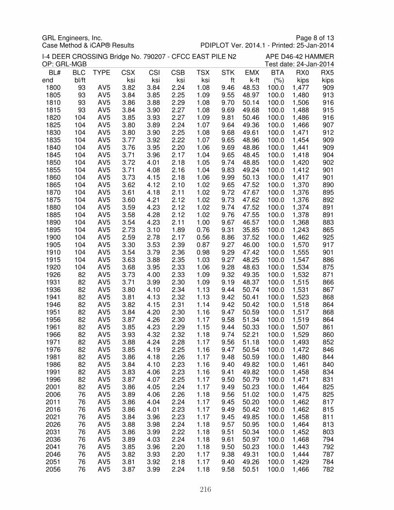
GRL Engineers, Inc.Case Method & iCAP® Results PDIPLOT Ver. 2014.1 - Printed: 25-Jan-2014
I-4 DEER CROSSING Bridge No. 790207 - CFCC EAST PILE N2 APE D46-42 HAMMEROP: GRL-MGB Test date: 24-Jan-2014
BL# BLC TYPE CSX CSI CSB TSX STK EMX BTA RX0 RX5end bl/ft ksi ksi ksi ksi ft k-ft (%) kips kips 1800 93 AV5 3.82 3.84 2.24 1.08 9.46 48.53 100.0 1,477 909 1805 93 AV5 3.84 3.85 2.25 1.09 9.55 48.97 100.0 1,480 913 1810 93 AV5 3.86 3.88 2.29 1.08 9.70 50.14 100.0 1,506 916 1815 93 AV5 3.84 3.90 2.27 1.08 9.69 49.68 100.0 1,488 915 1820 104 AV5 3.85 3.93 2.27 1.09 9.81 50.46 100.0 1,486 916 1825 104 AV5 3.80 3.89 2.24 1.07 9.64 49.36 100.0 1,466 907 1830 104 AV5 3.80 3.90 2.25 1.08 9.68 49.61 100.0 1,471 912 1835 104 AV5 3.77 3.92 2.22 1.07 9.65 48.96 100.0 1,454 909 1840 104 AV5 3.76 3.95 2.20 1.06 9.69 48.86 100.0 1,441 909 1845 104 AV5 3.71 3.96 2.17 1.04 9.65 48.45 100.0 1,418 904 1850 104 AV5 3.72 4.01 2.18 1.05 9.74 48.85 100.0 1,420 902 1855 104 AV5 3.71 4.08 2.16 1.04 9.83 49.24 100.0 1,412 901 1860 104 AV5 3.73 4.15 2.18 1.06 9.99 50.13 100.0 1,417 901 1865 104 AV5 3.62 4.12 2.10 1.02 9.65 47.52 100.0 1,370 890 1870 104 AV5 3.61 4.18 2.11 1.02 9.72 47.67 100.0 1,376 895 1875 104 AV5 3.60 4.21 2.12 1.02 9.73 47.62 100.0 1,376 892 1880 104 AV5 3.59 4.23 2.12 1.02 9.74 47.52 100.0 1,374 891 1885 104 AV5 3.58 4.28 2.12 1.02 9.76 47.55 100.0 1,378 891 1890 104 AV5 3.54 4.23 2.11 1.00 9.67 46.57 100.0 1,368 883 1895 104 AV5 2.73 3.10 1.89 0.76 9.31 35.85 100.0 1,243 865 1900 104 AV5 2.59 2.78 2.17 0.56 8.86 37.52 100.0 1,462 925 1905 104 AV5 3.30 3.53 2.39 0.87 9.27 46.00 100.0 1,570 917 1910 104 AV5 3.54 3.79 2.36 0.98 9.29 47.42 100.0 1,555 901 1915 104 AV5 3.63 3.88 2.35 1.03 9.27 48.25 100.0 1,547 886 1920 104 AV5 3.68 3.95 2.33 1.06 9.28 48.63 100.0 1,534 875 1926 82 AV5 3.73 4.00 2.33 1.09 9.32 49.35 100.0 1,532 871 1931 82 AV5 3.71 3.99 2.30 1.09 9.19 48.37 100.0 1,515 866 1936 82 AV5 3.80 4.10 2.34 1.13 9.44 50.74 100.0 1,531 867 1941 82 AV5 3.81 4.13 2.32 1.13 9.42 50.41 100.0 1,523 868 1946 82 AV5 3.82 4.15 2.31 1.14 9.42 50.42 100.0 1,518 864 1951 82 AV5 3.84 4.20 2.30 1.16 9.47 50.59 100.0 1,517 868 1956 82 AV5 3.87 4.26 2.30 1.17 9.58 51.34 100.0 1,519 864 1961 82 AV5 3.85 4.23 2.29 1.15 9.44 50.33 100.0 1,507 861 1966 82 AV5 3.93 4.32 2.32 1.18 9.74 52.21 100.0 1,529 860 1971 82 AV5 3.88 4.24 2.28 1.17 9.56 51.18 100.0 1,493 852 1976 82 AV5 3.85 4.19 2.25 1.16 9.47 50.54 100.0 1,472 846 1981 82 AV5 3.86 4.18 2.26 1.17 9.48 50.59 100.0 1,480 844 1986 82 AV5 3.84 4.10 2.23 1.16 9.40 49.82 100.0 1,461 840 1991 82 AV5 3.83 4.06 2.23 1.16 9.41 49.82 100.0 1,458 834 1996 82 AV5 3.87 4.07 2.25 1.17 9.50 50.79 100.0 1,471 831 2001 82 AV5 3.86 4.05 2.24 1.17 9.49 50.23 100.0 1,464 825 2006 76 AV5 3.89 4.06 2.26 1.18 9.56 51.02 100.0 1,475 825 2011 76 AV5 3.86 4.04 2.24 1.17 9.45 50.20 100.0 1,462 817 2016 76 AV5 3.86 4.01 2.23 1.17 9.49 50.42 100.0 1,462 815 2021 76 AV5 3.84 3.96 2.23 1.17 9.45 49.85 100.0 1,458 811 2026 76 AV5 3.88 3.98 2.24 1.18 9.57 50.95 100.0 1,464 813 2031 76 AV5 3.86 3.99 2.22 1.18 9.51 50.34 100.0 1,452 803 2036 76 AV5 3.89 4.03 2.24 1.18 9.61 50.97 100.0 1,468 794 2041 76 AV5 3.85 3.96 2.20 1.18 9.50 50.23 100.0 1,443 792 2046 76 AV5 3.82 3.93 2.20 1.17 9.38 49.31 100.0 1,444 787 2051 76 AV5 3.81 3.92 2.18 1.17 9.40 49.26 100.0 1,429 784 2056 76 AV5 3.87 3.99 2.24 1.18 9.58 50.51 100.0 1,466 782
Page 8 of 13
216

GRL Engineers, Inc.Case Method & iCAP® Results PDIPLOT Ver. 2014.1 - Printed: 25-Jan-2014
I-4 DEER CROSSING Bridge No. 790207 - CFCC EAST PILE N2 APE D46-42 HAMMEROP: GRL-MGB Test date: 24-Jan-2014
BL# BLC TYPE CSX CSI CSB TSX STK EMX BTA RX0 RX5end bl/ft ksi ksi ksi ksi ft k-ft (%) kips kips 2061 76 AV5 3.85 3.98 2.20 1.18 9.54 50.46 100.0 1,447 782 2066 76 AV5 3.83 3.95 2.19 1.17 9.48 49.52 100.0 1,441 773 2071 76 AV5 3.84 3.94 2.19 1.17 9.54 49.69 100.0 1,443 772 2076 76 AV5 3.84 3.95 2.16 1.17 9.55 49.98 100.0 1,431 769 2081 76 AV5 3.85 3.95 2.20 1.18 9.61 50.50 100.0 1,455 772 2086 68 AV5 3.83 3.94 2.17 1.17 9.53 49.69 100.0 1,437 766 2091 68 AV5 3.80 3.90 2.14 1.16 9.45 49.07 100.0 1,422 761 2096 68 AV5 3.79 3.88 2.11 1.16 9.41 49.00 100.0 1,407 763 2101 68 AV5 3.81 3.92 2.16 1.17 9.55 49.49 100.0 1,437 759 2106 68 AV5 3.80 3.92 2.14 1.16 9.53 49.39 100.0 1,430 757 2111 68 AV5 3.78 3.88 2.15 1.16 9.47 48.74 100.0 1,436 749 2116 68 AV5 3.78 3.88 2.14 1.16 9.49 48.49 100.0 1,434 742 2121 68 AV5 3.81 3.91 2.19 1.16 9.63 49.81 100.0 1,462 753 2127 68 AV5 3.81 3.91 2.20 1.17 9.68 49.55 100.0 1,469 744 2132 68 AV5 3.82 3.94 2.20 1.16 9.69 50.02 100.0 1,469 749 2137 68 AV5 3.78 3.91 2.17 1.15 9.53 48.91 100.0 1,456 738 2142 68 AV5 3.71 3.82 2.12 1.13 9.32 46.93 100.0 1,422 724 2147 68 AV5 3.76 3.87 2.16 1.14 9.49 48.18 100.0 1,450 726 2152 63 AV5 3.75 3.87 2.15 1.13 9.46 48.00 100.0 1,444 725 2157 63 AV5 3.73 3.86 2.15 1.13 9.42 47.69 100.0 1,442 724 2162 63 AV5 3.73 3.84 2.13 1.13 9.42 47.71 100.0 1,434 723 2167 63 AV5 3.73 3.87 2.14 1.13 9.44 47.96 100.0 1,434 723 2172 63 AV5 3.76 3.89 2.16 1.15 9.63 48.77 100.0 1,452 722 2177 63 AV5 3.71 3.82 2.11 1.13 9.44 47.23 100.0 1,427 712 2182 63 AV5 3.71 3.83 2.12 1.13 9.45 47.62 100.0 1,429 716 2187 63 AV5 3.73 3.83 2.13 1.14 9.55 48.00 100.0 1,437 711 2192 63 AV5 3.72 3.81 2.11 1.14 9.51 47.62 100.0 1,428 709 2197 63 AV5 3.70 3.78 2.08 1.13 9.43 47.13 100.0 1,414 709 2202 63 AV5 3.71 3.80 2.10 1.13 9.51 47.38 100.0 1,431 707 2207 63 AV5 3.70 3.80 2.09 1.13 9.49 47.29 100.0 1,425 709 2212 63 AV5 3.69 3.77 2.08 1.12 9.44 46.74 100.0 1,418 698 2217 57 AV5 3.63 3.73 2.03 1.10 9.30 45.63 100.0 1,391 694 2222 57 AV5 3.65 3.76 2.04 1.11 9.37 46.16 100.0 1,401 698 2227 57 AV5 3.68 3.77 2.07 1.12 9.45 46.95 100.0 1,415 697 2232 57 AV5 3.67 3.78 2.06 1.11 9.44 46.73 100.0 1,411 696 2237 57 AV5 3.65 3.76 2.05 1.11 9.39 46.19 100.0 1,406 693 2242 57 AV5 3.69 3.80 2.06 1.11 9.50 47.09 100.0 1,418 697 2247 57 AV5 3.67 3.80 2.06 1.10 9.46 46.62 100.0 1,418 693 2252 57 AV5 3.71 3.86 2.07 1.11 9.61 47.81 100.0 1,432 707 2257 57 AV5 3.70 3.85 2.06 1.10 9.60 47.60 100.0 1,428 708 2262 57 AV5 3.68 3.85 2.03 1.09 9.53 46.86 100.0 1,412 704 2267 57 AV5 3.66 3.82 2.02 1.09 9.46 46.33 100.0 1,406 700 2272 54 AV5 3.70 3.85 2.05 1.10 9.59 47.19 100.0 1,428 711 2277 54 AV5 3.65 3.82 2.01 1.08 9.44 45.96 100.0 1,403 698 2282 54 AV5 3.67 3.84 2.02 1.08 9.45 46.25 100.0 1,417 705 2287 54 AV5 3.68 3.86 2.03 1.08 9.50 46.48 100.0 1,423 706 2292 54 AV5 3.69 3.85 2.02 1.08 9.54 46.78 100.0 1,420 711 2297 54 AV5 3.70 3.89 2.05 1.08 9.54 46.85 100.0 1,440 706 2302 54 AV5 3.68 3.89 2.01 1.07 9.50 46.19 100.0 1,417 701 2307 54 AV5 3.73 3.94 2.04 1.08 9.65 47.11 100.0 1,443 707 2312 54 AV5 3.69 3.90 2.01 1.06 9.48 46.11 100.0 1,422 704 2317 54 AV5 3.72 3.92 2.05 1.07 9.54 46.73 100.0 1,446 708
Page 9 of 13
217
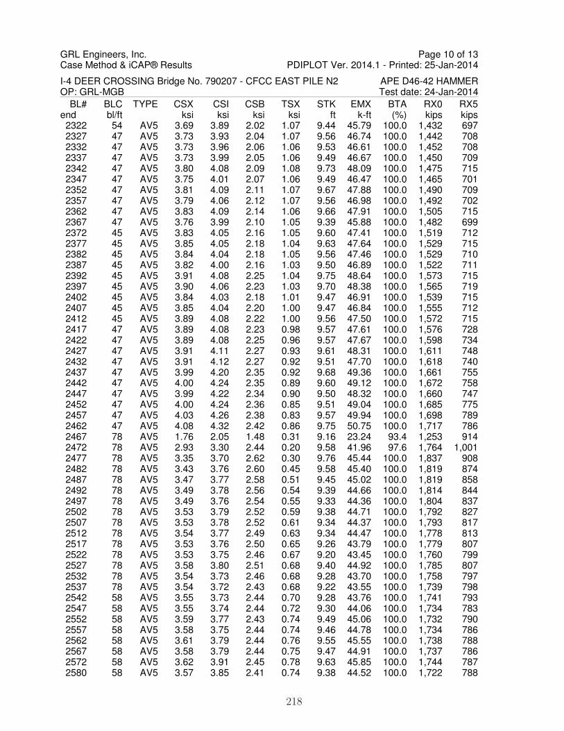
GRL Engineers, Inc.Case Method & iCAP® Results PDIPLOT Ver. 2014.1 - Printed: 25-Jan-2014
I-4 DEER CROSSING Bridge No. 790207 - CFCC EAST PILE N2 APE D46-42 HAMMEROP: GRL-MGB Test date: 24-Jan-2014
BL# BLC TYPE CSX CSI CSB TSX STK EMX BTA RX0 RX5end bl/ft ksi ksi ksi ksi ft k-ft (%) kips kips 2322 54 AV5 3.69 3.89 2.02 1.07 9.44 45.79 100.0 1,432 697 2327 47 AV5 3.73 3.93 2.04 1.07 9.56 46.74 100.0 1,442 708 2332 47 AV5 3.73 3.96 2.06 1.06 9.53 46.61 100.0 1,452 708 2337 47 AV5 3.73 3.99 2.05 1.06 9.49 46.67 100.0 1,450 709 2342 47 AV5 3.80 4.08 2.09 1.08 9.73 48.09 100.0 1,475 715 2347 47 AV5 3.75 4.01 2.07 1.06 9.49 46.47 100.0 1,465 701 2352 47 AV5 3.81 4.09 2.11 1.07 9.67 47.88 100.0 1,490 709 2357 47 AV5 3.79 4.06 2.12 1.07 9.56 46.98 100.0 1,492 702 2362 47 AV5 3.83 4.09 2.14 1.06 9.66 47.91 100.0 1,505 715 2367 47 AV5 3.76 3.99 2.10 1.05 9.39 45.88 100.0 1,482 699 2372 45 AV5 3.83 4.05 2.16 1.05 9.60 47.41 100.0 1,519 712 2377 45 AV5 3.85 4.05 2.18 1.04 9.63 47.64 100.0 1,529 715 2382 45 AV5 3.84 4.04 2.18 1.05 9.56 47.46 100.0 1,529 710 2387 45 AV5 3.82 4.00 2.16 1.03 9.50 46.89 100.0 1,522 711 2392 45 AV5 3.91 4.08 2.25 1.04 9.75 48.64 100.0 1,573 715 2397 45 AV5 3.90 4.06 2.23 1.03 9.70 48.38 100.0 1,565 719 2402 45 AV5 3.84 4.03 2.18 1.01 9.47 46.91 100.0 1,539 715 2407 45 AV5 3.85 4.04 2.20 1.00 9.47 46.84 100.0 1,555 712 2412 45 AV5 3.89 4.08 2.22 1.00 9.56 47.50 100.0 1,572 715 2417 47 AV5 3.89 4.08 2.23 0.98 9.57 47.61 100.0 1,576 728 2422 47 AV5 3.89 4.08 2.25 0.96 9.57 47.67 100.0 1,598 734 2427 47 AV5 3.91 4.11 2.27 0.93 9.61 48.31 100.0 1,611 748 2432 47 AV5 3.91 4.12 2.27 0.92 9.51 47.70 100.0 1,618 740 2437 47 AV5 3.99 4.20 2.35 0.92 9.68 49.36 100.0 1,661 755 2442 47 AV5 4.00 4.24 2.35 0.89 9.60 49.12 100.0 1,672 758 2447 47 AV5 3.99 4.22 2.34 0.90 9.50 48.32 100.0 1,660 747 2452 47 AV5 4.00 4.24 2.36 0.85 9.51 49.04 100.0 1,685 775 2457 47 AV5 4.03 4.26 2.38 0.83 9.57 49.94 100.0 1,698 789 2462 47 AV5 4.08 4.32 2.42 0.86 9.75 50.75 100.0 1,717 786 2467 78 AV5 1.76 2.05 1.48 0.31 9.16 23.24 93.4 1,253 914 2472 78 AV5 2.93 3.30 2.44 0.20 9.58 41.96 97.6 1,764 1,001 2477 78 AV5 3.35 3.70 2.62 0.30 9.76 45.44 100.0 1,837 908 2482 78 AV5 3.43 3.76 2.60 0.45 9.58 45.40 100.0 1,819 874 2487 78 AV5 3.47 3.77 2.58 0.51 9.45 45.02 100.0 1,819 858 2492 78 AV5 3.49 3.78 2.56 0.54 9.39 44.66 100.0 1,814 844 2497 78 AV5 3.49 3.76 2.54 0.55 9.33 44.36 100.0 1,804 837 2502 78 AV5 3.53 3.79 2.52 0.59 9.38 44.71 100.0 1,792 827 2507 78 AV5 3.53 3.78 2.52 0.61 9.34 44.37 100.0 1,793 817 2512 78 AV5 3.54 3.77 2.49 0.63 9.34 44.47 100.0 1,778 813 2517 78 AV5 3.53 3.76 2.50 0.65 9.26 43.79 100.0 1,779 807 2522 78 AV5 3.53 3.75 2.46 0.67 9.20 43.45 100.0 1,760 799 2527 78 AV5 3.58 3.80 2.51 0.68 9.40 44.92 100.0 1,785 807 2532 78 AV5 3.54 3.73 2.46 0.68 9.28 43.70 100.0 1,758 797 2537 78 AV5 3.54 3.72 2.43 0.68 9.22 43.55 100.0 1,739 798 2542 58 AV5 3.55 3.73 2.44 0.70 9.28 43.76 100.0 1,741 793 2547 58 AV5 3.55 3.74 2.44 0.72 9.30 44.06 100.0 1,734 783 2552 58 AV5 3.59 3.77 2.43 0.74 9.49 45.06 100.0 1,732 790 2557 58 AV5 3.58 3.75 2.44 0.74 9.46 44.78 100.0 1,734 786 2562 58 AV5 3.61 3.79 2.44 0.76 9.55 45.55 100.0 1,738 788 2567 58 AV5 3.58 3.79 2.44 0.75 9.47 44.91 100.0 1,737 786 2572 58 AV5 3.62 3.91 2.45 0.78 9.63 45.85 100.0 1,744 787 2580 58 AV5 3.57 3.85 2.41 0.74 9.38 44.52 100.0 1,722 788
Page 10 of 13
218

GRL Engineers, Inc.Case Method & iCAP® Results PDIPLOT Ver. 2014.1 - Printed: 25-Jan-2014
I-4 DEER CROSSING Bridge No. 790207 - CFCC EAST PILE N2 APE D46-42 HAMMEROP: GRL-MGB Test date: 24-Jan-2014
BL# BLC TYPE CSX CSI CSB TSX STK EMX BTA RX0 RX5end bl/ft ksi ksi ksi ksi ft k-ft (%) kips kips 2585 58 AV5 3.59 3.85 2.43 0.75 9.41 44.90 100.0 1,729 782 2590 58 AV5 3.58 3.82 2.42 0.76 9.34 44.49 100.0 1,724 780 2595 58 AV5 3.57 3.82 2.39 0.77 9.32 44.39 100.0 1,710 779 2600 57 AV5 3.52 3.80 2.37 0.80 9.31 44.62 100.0 1,694 777 2605 57 AV5 3.57 3.86 2.42 0.83 9.53 46.80 100.0 1,724 792 2610 57 AV5 3.59 3.88 2.39 0.83 9.56 47.13 100.0 1,710 794 2615 57 AV5 3.57 3.87 2.41 0.80 9.50 46.68 100.0 1,723 800 2620 57 AV5 3.57 3.86 2.38 0.81 9.53 46.61 100.0 1,710 797 2625 57 AV5 3.59 3.88 2.41 0.81 9.55 47.11 100.0 1,727 800 2630 57 AV5 3.55 3.82 2.36 0.81 9.45 45.99 100.0 1,699 791 2635 57 AV5 2.83 3.03 1.91 0.64 6.53 36.58 83.6 1,374 635 2640 57 AV5 3.51 3.75 2.36 0.77 9.34 45.04 100.0 1,700 791 2645 57 AV5 3.52 3.74 2.33 0.76 9.40 45.31 100.0 1,686 797 2650 57 AV5 3.50 3.70 2.34 0.74 9.39 45.05 100.0 1,687 798 2655 57 AV5 3.50 3.69 2.33 0.75 9.41 44.82 100.0 1,680 787 2660 63 AV5 3.24 3.35 2.25 0.53 9.18 39.09 100.0 1,623 797 2665 63 AV5 3.70 3.76 2.47 0.62 9.41 45.36 100.0 1,769 816 2670 63 AV5 3.68 3.74 2.45 0.62 9.36 44.76 100.0 1,753 806 2675 63 AV5 3.68 3.74 2.43 0.63 9.34 44.71 100.0 1,738 800 2680 63 AV5 3.70 3.77 2.44 0.64 9.44 45.57 100.0 1,748 804 2685 63 AV5 3.69 3.77 2.42 0.64 9.44 45.23 100.0 1,738 802 2691 63 AV5 3.63 3.70 2.38 0.62 9.18 43.86 100.0 1,715 799 2696 63 AV5 3.64 3.71 2.39 0.64 9.28 44.18 100.0 1,715 793 2701 63 AV5 3.61 3.70 2.38 0.61 9.26 43.55 100.0 1,714 795 2706 63 AV5 3.64 3.72 2.39 0.61 9.40 44.36 100.0 1,719 799 2711 63 AV5 3.61 3.71 2.38 0.59 9.34 43.91 100.0 1,709 797 2716 63 AV5 3.60 3.73 2.38 0.58 9.34 43.95 100.0 1,704 794 2721 64 AV5 3.62 3.74 2.37 0.59 9.41 44.12 100.0 1,701 793 2726 64 AV5 3.60 3.72 2.35 0.58 9.32 43.70 100.0 1,691 795 2731 64 AV5 3.58 3.70 2.36 0.59 9.32 43.67 100.0 1,694 795 2736 64 AV5 3.57 3.68 2.35 0.60 9.39 43.88 100.0 1,693 801 2741 64 AV5 3.55 3.69 2.34 0.60 9.37 43.52 100.0 1,688 799 2746 64 AV5 3.56 3.70 2.34 0.60 9.42 43.82 100.0 1,687 802 2751 64 AV5 3.56 3.70 2.33 0.59 9.43 43.88 100.0 1,684 809 2756 64 AV5 3.54 3.69 2.33 0.58 9.38 43.75 100.0 1,679 813 2761 64 AV5 3.55 3.70 2.32 0.58 9.43 43.87 100.0 1,680 822 2766 64 AV5 3.53 3.67 2.31 0.58 9.38 43.27 100.0 1,671 817 2771 64 AV5 3.54 3.69 2.33 0.58 9.44 43.93 100.0 1,675 825 2776 64 AV5 3.52 3.68 2.32 0.57 9.38 43.17 100.0 1,670 828 2781 64 AV5 3.50 3.65 2.29 0.59 9.29 42.82 100.0 1,653 826 2786 62 AV5 3.52 3.69 2.29 0.60 9.40 43.52 100.0 1,650 828 2791 62 AV5 3.48 3.64 2.26 0.60 9.27 42.49 100.0 1,629 824 2796 62 AV5 3.51 3.68 2.27 0.62 9.38 43.21 100.0 1,634 828 2802 62 AV5 3.49 3.69 2.24 0.63 9.29 42.69 100.0 1,623 832 2807 62 AV5 3.50 3.73 2.26 0.62 9.36 43.09 100.0 1,632 848 2812 62 AV5 3.51 3.74 2.27 0.63 9.45 43.54 100.0 1,634 851 2817 62 AV5 3.50 3.73 2.28 0.61 9.37 43.21 100.0 1,633 862 2822 62 AV5 3.51 3.72 2.28 0.61 9.39 43.08 100.0 1,636 878 2827 62 AV5 3.53 3.74 2.30 0.60 9.52 44.06 100.0 1,646 893 2832 62 AV5 3.50 3.69 2.30 0.59 9.49 43.44 100.0 1,639 905 2837 62 AV5 3.53 3.72 2.33 0.59 9.63 44.43 100.0 1,655 931 2842 62 AV5 3.52 3.71 2.33 0.59 9.63 44.26 100.0 1,648 948
Page 11 of 13
219

GRL Engineers, Inc.Case Method & iCAP® Results PDIPLOT Ver. 2014.1 - Printed: 25-Jan-2014
I-4 DEER CROSSING Bridge No. 790207 - CFCC EAST PILE N2 APE D46-42 HAMMEROP: GRL-MGB Test date: 24-Jan-2014
BL# BLC TYPE CSX CSI CSB TSX STK EMX BTA RX0 RX5end bl/ft ksi ksi ksi ksi ft k-ft (%) kips kips 2847 67 AV5 3.54 3.72 2.35 0.61 9.67 44.64 100.0 1,649 977 2852 67 AV5 3.52 3.70 2.36 0.60 9.56 44.03 100.0 1,646 1,006 2857 67 AV5 3.56 3.75 2.38 0.61 9.73 45.18 100.0 1,656 1,036 2862 67 AV5 3.55 3.73 2.39 0.61 9.73 45.11 100.0 1,656 1,052 2867 67 AV5 3.54 3.73 2.40 0.61 9.71 44.85 100.0 1,657 1,051 2872 67 AV5 3.55 3.74 2.42 0.59 9.72 45.13 100.0 1,668 1,052 2877 67 AV5 3.54 3.73 2.43 0.58 9.70 44.87 100.0 1,675 1,048 2882 67 AV5 3.51 3.70 2.45 0.54 9.55 44.10 100.0 1,680 1,036 2887 67 AV5 3.55 3.74 2.49 0.54 9.74 45.29 100.0 1,706 1,036 2892 67 AV5 3.53 3.70 2.50 0.51 9.64 44.76 100.0 1,715 1,027 2897 67 AV5 3.56 3.72 2.52 0.50 9.75 44.99 100.0 1,725 1,019 2902 67 AV5 3.56 3.71 2.52 0.48 9.75 45.04 100.0 1,734 1,015 2907 67 AV5 3.58 3.74 2.53 0.48 9.85 45.58 100.0 1,740 1,015 2913 67 AV5 3.56 3.71 2.53 0.45 9.77 45.09 100.0 1,738 1,012 2918 67 AV5 3.58 3.74 2.54 0.45 9.77 45.49 100.0 1,749 1,019 2923 67 AV5 3.58 3.74 2.53 0.47 9.79 45.32 100.0 1,740 1,015 2928 67 AV5 3.57 3.72 2.52 0.47 9.76 45.12 100.0 1,739 1,016 2933 67 AV5 3.63 3.77 2.55 0.49 10.03 46.81 100.0 1,761 1,030 2938 67 AV5 3.60 3.73 2.54 0.47 9.87 45.78 100.0 1,752 1,030 2943 67 AV5 3.61 3.75 2.55 0.47 9.89 45.79 100.0 1,761 1,038 2948 67 AV5 3.61 3.75 2.55 0.46 9.86 45.94 100.0 1,760 1,043 2953 67 AV5 3.61 3.75 2.55 0.46 9.82 45.65 100.0 1,759 1,048 2958 67 AV5 3.59 3.73 2.55 0.47 9.78 45.14 100.0 1,755 1,052 2963 67 AV5 3.60 3.74 2.56 0.46 9.77 45.35 100.0 1,758 1,064 2968 67 AV5 3.15 3.26 2.38 0.36 8.81 35.29 97.8 1,634 1,026 2973 67 AV5 3.82 3.93 2.82 0.46 9.89 48.74 100.0 1,908 1,132 2978 67 AV5 3.80 3.93 2.77 0.49 9.71 47.45 100.0 1,877 1,118 2983 73 AV5 3.83 3.96 2.77 0.52 9.81 48.04 100.0 1,881 1,132 2988 73 AV5 3.81 3.96 2.73 0.54 9.79 47.55 100.0 1,860 1,130 2993 73 AV5 3.81 3.97 2.71 0.55 9.78 47.60 100.0 1,843 1,135 2998 73 AV5 3.79 3.95 2.68 0.56 9.71 46.95 100.0 1,821 1,134 3003 73 AV5 3.85 4.02 2.69 0.61 9.93 48.21 100.0 1,826 1,144 3008 73 AV5 3.83 4.02 2.66 0.62 9.87 47.59 100.0 1,807 1,147 3013 73 AV5 3.75 3.94 2.60 0.61 9.57 45.71 100.0 1,761 1,140 3018 73 AV5 3.85 4.05 2.64 0.67 9.91 48.01 100.0 1,790 1,163 3024 73 AV5 3.88 4.08 2.65 0.69 10.03 48.92 100.0 1,792 1,173 3029 73 AV5 3.81 4.00 2.59 0.67 9.82 47.32 100.0 1,755 1,180 3034 73 AV5 3.80 4.01 2.58 0.69 9.73 46.86 100.0 1,742 1,193 3039 73 AV5 3.85 4.08 2.60 0.73 9.93 48.08 100.0 1,751 1,216 3044 73 AV5 3.83 4.02 2.58 0.73 9.84 47.58 100.0 1,734 1,231 3049 73 AV5 3.86 4.05 2.59 0.76 9.94 48.69 100.0 1,738 1,249 3054 88 AV5 3.87 4.08 2.60 0.78 9.94 48.59 100.0 1,740 1,262 3059 88 AV5 3.82 4.01 2.61 0.75 9.81 47.20 100.0 1,744 1,286 3064 88 AV5 3.81 3.99 2.65 0.75 9.80 47.18 100.0 1,763 1,315 3069 88 AV5 3.82 3.99 2.71 0.75 9.82 47.33 100.0 1,790 1,350 3074 88 AV5 3.87 4.04 2.76 0.79 9.96 48.44 100.0 1,819 1,373 3079 88 AV5 3.91 4.11 2.82 0.82 10.12 49.64 100.0 1,847 1,396 3084 88 AV5 3.85 4.05 2.83 0.80 9.91 48.18 100.0 1,845 1,412 3089 88 AV5 3.85 4.06 2.86 0.81 9.91 48.14 100.0 1,862 1,438 3094 88 AV5 3.85 4.05 2.89 0.82 9.92 48.05 100.0 1,871 1,456 3099 88 AV5 3.86 4.06 2.94 0.83 9.90 48.41 100.0 1,895 1,481 3104 88 AV5 3.81 4.00 2.94 0.82 9.72 47.08 100.0 1,894 1,507
Page 12 of 13
220

GRL Engineers, Inc.Case Method & iCAP® Results PDIPLOT Ver. 2014.1 - Printed: 25-Jan-2014
I-4 DEER CROSSING Bridge No. 790207 - CFCC EAST PILE N2 APE D46-42 HAMMEROP: GRL-MGB Test date: 24-Jan-2014
BL# BLC TYPE CSX CSI CSB TSX STK EMX BTA RX0 RX5end bl/ft ksi ksi ksi ksi ft k-ft (%) kips kips 3109 88 AV5 3.88 4.07 3.01 0.85 9.96 48.71 100.0 1,936 1,548 3114 88 AV5 3.88 4.07 3.05 0.85 9.98 48.75 100.0 1,949 1,568 3119 88 AV5 3.86 4.04 3.06 0.86 9.92 48.23 100.0 1,952 1,585 3124 88 AV5 3.89 4.06 3.12 0.86 10.00 48.89 100.0 1,981 1,618 3129 88 AV5 3.86 4.02 3.13 0.86 9.91 48.11 100.0 1,988 1,642 3134 88 AV5 3.89 4.05 3.19 0.86 10.02 49.01 100.0 2,017 1,674 3139 88 AV5 3.88 4.05 3.21 0.87 10.00 48.91 100.0 2,028 1,690
Page 13 of 13
221

1
1 -
Cha
nge
Pile
Cus
hion
Tes
t dat
e: 2
4-Ja
n-20
14
Max
Cas
e M
etho
d C
apac
ity (
JC=
0.5)
Max
Cas
e M
etho
d C
apac
ity (
JC=
0)
Blo
w C
ount
O.E
. Die
sel H
amm
er S
trok
e
Ten
sion
Str
ess
Max
imum
Max
Mea
sure
d C
ompr
. Str
ess
PD
IPLO
T V
er. 2
014.
1 -
Prin
ted:
25-
Jan-
2014
GR
L E
ngin
eers
, Inc
. - C
ase
Met
hod
& iC
AP
® R
esul
ts
I-4
DE
ER
CR
OS
SIN
G B
ridge
No.
790
207
- C
FC
C E
AS
T P
ILE
N2
10
CS
X (
ksi)
0
TS
X (
ksi)
0
BLC
(bl
ows/
ft)
0
ST
K (
ft)
0
RX
5 (k
ips)
0
RX
0 (k
ips)
0
P e n e t r a t i o n f t
20 30 40 50 60 70 80 90 100
110
2
2 -
Cha
nge
Pile
Cus
hion
3
3 -
Cha
nge
Pile
Cus
hion
24
68
36
912
600
1,20
01,
800
2,40
0
12
34
3060
9012
060
01,
200
1,80
02,
400
222

GRL Engineers, Inc.Case Method & iCAP® Results PDIPLOT Ver. 2014.1 - Printed: 25-Jan-2014
I-4 DEER CROSSING Bridge No. 790207 - CFCC EAST PILE N2 APE D46-42 HAMMEROP: GRL-MGB Test date: 24-Jan-2014AR: 576.00 in^2 SP: 0.145 k/ft3LE: 95.00 ft EM: 6,178 ksiWS: 14,050.0 f/s JC: 0.50CSX: Max Measured Compr. StressCSI: Max F1 or F2 Compr. StressCSB: Compression Stress at BottomTSX: Tension Stress MaximumSTK: O.E. Diesel Hammer Stroke
EMX: Max Transferred EnergyBTA: BETA Integrity FactorRX0: Max Case Method Capacity (JC=0)RX5: Max Case Method Capacity (JC=0.5)
BL# depth BLC TYPE CSX CSI CSB TSX STK EMX BTA RX0 RX5end ft bl/ft ksi ksi ksi ksi ft k-ft (%) kips kips
5 27.00 5 AV5 1.71 2.11 0.54 1.07 7.08 29.37 97.6 314 21 10 28.00 5 AV5 2.07 2.58 0.70 1.33 6.33 28.75 100.0 408 109 20 29.00 10 AV10 2.09 2.51 0.75 1.32 5.99 25.62 100.0 438 179 30 30.00 10 AV10 2.34 2.77 0.95 1.42 6.82 32.21 100.0 556 282 41 31.00 11 AV11 2.57 3.04 1.16 1.47 7.50 36.72 100.0 685 404 53 32.00 12 AV12 2.77 3.29 1.37 1.48 7.99 39.93 100.0 805 522 66 33.00 13 AV11 2.83 3.35 1.46 1.48 7.99 40.26 100.0 857 562 80 34.00 14 AV14 2.88 3.40 1.50 1.50 8.11 40.63 100.0 882 600 95 35.00 15 AV15 2.93 3.46 1.51 1.50 8.23 41.21 100.0 892 617
111 36.00 16 AV16 2.97 3.55 1.52 1.49 8.34 41.59 100.0 896 564 130 37.00 19 AV19 3.00 3.59 1.55 1.46 8.41 41.96 100.0 916 553 149 38.00 19 AV18 3.02 3.58 1.57 1.44 8.47 42.07 100.0 926 536 172 39.00 23 AV23 2.99 3.58 1.55 1.42 8.37 40.72 100.0 915 482 196 40.00 24 AV24 3.02 3.63 1.58 1.41 8.52 41.54 100.0 934 484 221 41.00 25 AV24 3.06 3.71 1.61 1.39 8.68 42.24 100.0 952 483 246 42.00 25 AV25 3.08 3.75 1.63 1.39 8.82 42.88 100.0 965 492 272 43.00 26 AV25 3.04 3.74 1.59 1.37 8.70 41.96 100.0 940 497 296 44.00 24 AV24 3.04 3.76 1.59 1.38 8.73 42.20 100.0 940 495 319 45.00 23 AV23 3.03 3.76 1.56 1.38 8.66 41.75 100.0 926 495 339 46.00 20 AV19 3.06 3.76 1.58 1.39 8.68 42.27 100.0 938 510 359 47.00 20 AV20 3.13 3.83 1.62 1.40 8.92 43.78 100.0 968 512 381 48.00 22 AV22 3.14 3.83 1.64 1.39 8.89 43.09 100.0 980 525 409 49.00 28 AV27 3.20 3.89 1.66 1.39 8.99 43.15 100.0 1,026 585 430 50.00 21 AV21 3.27 3.98 1.70 1.38 9.12 44.60 100.0 1,059 610 458 51.00 28 AV28 3.31 4.04 1.73 1.37 9.10 44.68 100.0 1,095 646 489 52.00 31 AV30 3.39 4.12 1.78 1.35 9.24 45.64 100.0 1,136 675 524 53.00 35 AV35 3.44 4.13 1.82 1.33 9.19 45.30 100.0 1,171 694 558 54.00 34 AV33 3.63 4.30 2.04 1.30 9.32 46.85 100.0 1,321 709 593 55.00 35 AV35 3.73 4.38 2.12 1.32 9.34 48.25 100.0 1,395 737 632 56.00 39 AV38 3.73 4.35 2.11 1.30 9.39 48.33 100.0 1,394 748 672 57.00 40 AV39 3.74 4.36 2.13 1.30 9.44 48.89 100.0 1,401 723 711 58.00 39 AV39 3.73 4.37 2.09 1.31 9.31 48.40 100.0 1,402 701 751 59.00 40 AV39 3.72 4.32 2.06 1.30 9.31 48.23 100.0 1,405 717 788 60.00 37 AV37 3.70 4.28 2.01 1.29 9.34 47.90 100.0 1,396 710 823 61.00 35 AV34 3.66 4.23 1.94 1.28 9.30 47.39 100.0 1,383 695 858 62.00 35 AV34 3.59 4.16 1.84 1.25 9.18 45.77 100.0 1,363 699 892 63.00 34 AV34 3.51 4.08 1.68 1.23 9.21 45.09 100.0 1,321 707 929 64.00 37 AV36 3.40 3.81 1.54 1.19 9.17 42.95 100.0 1,294 700 966 65.00 37 AV37 3.31 3.50 1.42 1.17 9.23 41.93 100.0 1,264 688
1013 66.00 47 AV46 3.29 3.39 1.39 1.18 9.41 41.38 100.0 1,284 689 1038 67.00 25 AV25 3.33 3.47 1.47 1.15 9.50 41.81 100.0 1,328 664 1074 68.00 36 AV36 3.44 3.56 1.55 1.16 9.53 42.13 100.0 1,380 668 1107 69.00 33 AV33 3.76 3.90 1.98 1.19 9.56 44.77 100.0 1,573 663
Page 1 of 2
223

GRL Engineers, Inc.Case Method & iCAP® Results PDIPLOT Ver. 2014.1 - Printed: 25-Jan-2014
I-4 DEER CROSSING Bridge No. 790207 - CFCC EAST PILE N2 APE D46-42 HAMMEROP: GRL-MGB Test date: 24-Jan-2014
BL# depth BLC TYPE CSX CSI CSB TSX STK EMX BTA RX0 RX5end ft bl/ft ksi ksi ksi ksi ft k-ft (%) kips kips 1146 70.00 39 AV39 3.36 3.65 1.61 1.06 9.18 42.60 100.0 1,432 597 1181 71.00 35 AV35 3.69 4.15 1.69 1.33 9.21 47.75 100.0 1,475 609 1218 72.00 37 AV37 3.72 4.29 1.67 1.37 9.21 47.73 100.0 1,474 648 1255 73.00 37 AV37 3.69 4.26 1.69 1.38 9.15 46.94 100.0 1,452 643 1291 74.00 36 AV36 3.62 4.04 1.70 1.34 9.05 45.57 100.0 1,426 595 1328 75.00 37 AV35 3.58 3.90 1.72 1.31 9.06 44.87 100.0 1,397 546 1363 76.00 35 AV35 3.58 3.83 1.73 1.27 9.18 45.50 99.1 1,399 520 1399 77.00 36 AV36 3.54 3.81 1.71 1.21 9.22 45.16 99.7 1,396 506 1441 78.00 42 AV42 3.56 3.87 1.79 1.05 9.40 45.78 100.0 1,464 562 1495 79.00 54 AV54 3.62 3.89 1.99 0.81 9.60 46.92 98.7 1,597 807 1558 80.00 63 AV62 3.74 4.06 2.06 0.88 9.70 48.47 93.8 1,601 873 1636 81.00 78 AV78 3.85 4.19 2.14 1.02 9.68 49.27 91.7 1,578 887 1726 82.00 90 AV89 4.01 4.35 2.30 1.13 9.76 51.50 100.0 1,572 885 1819 83.00 93 AV93 3.94 4.07 2.32 1.10 9.72 50.69 100.0 1,533 913 1923 84.00 104 AV104 3.56 3.91 2.19 1.00 9.57 47.16 100.0 1,436 897 2005 85.00 82 AV81 3.84 4.14 2.28 1.15 9.47 50.51 100.0 1,497 852 2081 86.00 76 AV76 3.85 3.97 2.21 1.17 9.51 50.15 100.0 1,451 792 2149 87.00 68 AV67 3.79 3.90 2.16 1.16 9.51 48.93 100.0 1,440 748 2212 88.00 63 AV63 3.72 3.83 2.12 1.13 9.49 47.68 100.0 1,433 714 2269 89.00 57 AV57 3.67 3.80 2.05 1.11 9.47 46.75 100.0 1,414 699 2323 90.00 54 AV54 3.69 3.88 2.03 1.08 9.51 46.44 100.0 1,426 704 2370 91.00 47 AV47 3.78 4.03 2.09 1.06 9.58 47.12 100.0 1,478 708 2415 92.00 45 AV45 3.86 4.05 2.20 1.02 9.57 47.49 100.0 1,547 714 2462 93.00 47 AV47 3.97 4.19 2.33 0.90 9.59 48.86 100.0 1,655 758 2540 94.00 78 AV78 3.36 3.62 2.45 0.54 9.38 42.90 99.4 1,753 845 2598 95.00 58 AV55 3.58 3.81 2.43 0.75 9.43 44.83 100.0 1,728 785 2655 96.00 57 AV57 3.48 3.74 2.33 0.78 9.20 45.15 98.6 1,675 779 2718 97.00 63 AV62 3.62 3.70 2.40 0.61 9.34 44.06 100.0 1,720 800 2782 98.00 64 AV64 3.55 3.69 2.33 0.59 9.38 43.62 100.0 1,681 810 2844 99.00 62 AV61 3.51 3.71 2.29 0.61 9.43 43.42 100.0 1,638 873 2911 100.00 67 AV66 3.55 3.72 2.45 0.55 9.71 44.96 100.0 1,689 1,030 2978 101.00 67 AV67 3.59 3.73 2.57 0.46 9.76 45.19 99.8 1,764 1,047 3051 102.00 73 AV72 3.83 4.01 2.65 0.64 9.84 47.68 100.0 1,791 1,171 3139 103.00 88 AV88 3.86 4.04 2.92 0.82 9.92 48.26 100.0 1,888 1,483
Page 2 of 2
224

1
1 -
Cha
nge
Pile
Cus
hion
Tes
t dat
e: 2
4-Ja
n-20
14
Max
Cas
e M
etho
d C
apac
ity (
JC=
0.5)
Max
Cas
e M
etho
d C
apac
ity (
JC=
0)
Blo
w C
ount
O.E
. Die
sel H
amm
er S
trok
e
Ten
sion
Str
ess
Max
imum
Max
Mea
sure
d C
ompr
. Str
ess
PD
IPLO
T V
er. 2
014.
1 -
Prin
ted:
25-
Jan-
2014
GR
L E
ngin
eers
, Inc
. - C
ase
Met
hod
& iC
AP
® R
esul
ts
I-4
DE
ER
CR
OS
SIN
G B
ridge
No.
790
207
- C
FC
C E
AS
T P
ILE
N2
30.0
CS
X (
ksi)
0
TS
X (
ksi)
0
BLC
(bl
ows/
ft)
0
ST
K (
ft)
0
RX
5 (k
ips)
0
RX
0 (k
ips)
0
E l e v a t i o n
20.0
10.0 0.0
-10.
0
-20.
0
-30.
0
-40.
0
-50.
0
-60.
0
2
2 -
Cha
nge
Pile
Cus
hion
3
3 -
Cha
nge
Pile
Cus
hion
24
68
36
912
600
1,20
01,
800
2,40
0
12
34
3060
9012
060
01,
200
1,80
02,
400
225

GRL Engineers, Inc.Case Method & iCAP® Results PDIPLOT Ver. 2014.1 - Printed: 25-Jan-2014
I-4 DEER CROSSING Bridge No. 790207 - CFCC EAST PILE N2 APE D46-42 HAMMEROP: GRL-MGB Test date: 24-Jan-2014AR: 576.00 in^2 SP: 0.145 k/ft3LE: 95.00 ft EM: 6,178 ksiWS: 14,050.0 f/s JC: 0.50CSX: Max Measured Compr. StressCSI: Max F1 or F2 Compr. StressCSB: Compression Stress at BottomTSX: Tension Stress MaximumSTK: O.E. Diesel Hammer Stroke
EMX: Max Transferred EnergyBTA: BETA Integrity FactorRX0: Max Case Method Capacity (JC=0)RX5: Max Case Method Capacity (JC=0.5)
BL# Elev. BLC TYPE CSX CSI CSB TSX STK EMX BTA RX0 RX5end bl/ft ksi ksi ksi ksi ft k-ft (%) kips kips
5 25.4 5 AV5 1.71 2.11 0.54 1.07 7.08 29.37 97.6 314 21 10 24.4 5 AV5 2.07 2.58 0.70 1.33 6.33 28.75 100.0 408 109 20 23.4 10 AV10 2.09 2.51 0.75 1.32 5.99 25.62 100.0 438 179 30 22.4 10 AV10 2.34 2.77 0.95 1.42 6.82 32.21 100.0 556 282 41 21.4 11 AV11 2.57 3.04 1.16 1.47 7.50 36.72 100.0 685 404 53 20.4 12 AV12 2.77 3.29 1.37 1.48 7.99 39.93 100.0 805 522 66 19.4 13 AV11 2.83 3.35 1.46 1.48 7.99 40.26 100.0 857 562 80 18.4 14 AV14 2.88 3.40 1.50 1.50 8.11 40.63 100.0 882 600 95 17.4 15 AV15 2.93 3.46 1.51 1.50 8.23 41.21 100.0 892 617
111 16.4 16 AV16 2.97 3.55 1.52 1.49 8.34 41.59 100.0 896 564 130 15.4 19 AV19 3.00 3.59 1.55 1.46 8.41 41.96 100.0 916 553 149 14.4 19 AV18 3.02 3.58 1.57 1.44 8.47 42.07 100.0 926 536 172 13.4 23 AV23 2.99 3.58 1.55 1.42 8.37 40.72 100.0 915 482 196 12.4 24 AV24 3.02 3.63 1.58 1.41 8.52 41.54 100.0 934 484 221 11.4 25 AV24 3.06 3.71 1.61 1.39 8.68 42.24 100.0 952 483 246 10.4 25 AV25 3.08 3.75 1.63 1.39 8.82 42.88 100.0 965 492 272 9.4 26 AV25 3.04 3.74 1.59 1.37 8.70 41.96 100.0 940 497 296 8.4 24 AV24 3.04 3.76 1.59 1.38 8.73 42.20 100.0 940 495 319 7.4 23 AV23 3.03 3.76 1.56 1.38 8.66 41.75 100.0 926 495 339 6.4 20 AV19 3.06 3.76 1.58 1.39 8.68 42.27 100.0 938 510 359 5.4 20 AV20 3.13 3.83 1.62 1.40 8.92 43.78 100.0 968 512 381 4.4 22 AV22 3.14 3.83 1.64 1.39 8.89 43.09 100.0 980 525 409 3.4 28 AV27 3.20 3.89 1.66 1.39 8.99 43.15 100.0 1,026 585 430 2.4 21 AV21 3.27 3.98 1.70 1.38 9.12 44.60 100.0 1,059 610 458 1.4 28 AV28 3.31 4.04 1.73 1.37 9.10 44.68 100.0 1,095 646 489 0.4 31 AV30 3.39 4.12 1.78 1.35 9.24 45.64 100.0 1,136 675 524 -0.6 35 AV35 3.44 4.13 1.82 1.33 9.19 45.30 100.0 1,171 694 558 -1.6 34 AV33 3.63 4.30 2.04 1.30 9.32 46.85 100.0 1,321 709 593 -2.6 35 AV35 3.73 4.38 2.12 1.32 9.34 48.25 100.0 1,395 737 632 -3.6 39 AV38 3.73 4.35 2.11 1.30 9.39 48.33 100.0 1,394 748 672 -4.6 40 AV39 3.74 4.36 2.13 1.30 9.44 48.89 100.0 1,401 723 711 -5.6 39 AV39 3.73 4.37 2.09 1.31 9.31 48.40 100.0 1,402 701 751 -6.6 40 AV39 3.72 4.32 2.06 1.30 9.31 48.23 100.0 1,405 717 788 -7.6 37 AV37 3.70 4.28 2.01 1.29 9.34 47.90 100.0 1,396 710 823 -8.6 35 AV34 3.66 4.23 1.94 1.28 9.30 47.39 100.0 1,383 695 858 -9.6 35 AV34 3.59 4.16 1.84 1.25 9.18 45.77 100.0 1,363 699 892 -10.6 34 AV34 3.51 4.08 1.68 1.23 9.21 45.09 100.0 1,321 707 929 -11.6 37 AV36 3.40 3.81 1.54 1.19 9.17 42.95 100.0 1,294 700 966 -12.6 37 AV37 3.31 3.50 1.42 1.17 9.23 41.93 100.0 1,264 688
1013 -13.6 47 AV46 3.29 3.39 1.39 1.18 9.41 41.38 100.0 1,284 689 1038 -14.6 25 AV25 3.33 3.47 1.47 1.15 9.50 41.81 100.0 1,328 664 1074 -15.6 36 AV36 3.44 3.56 1.55 1.16 9.53 42.13 100.0 1,380 668 1107 -16.6 33 AV33 3.76 3.90 1.98 1.19 9.56 44.77 100.0 1,573 663
Page 1 of 2
226

GRL Engineers, Inc.Case Method & iCAP® Results PDIPLOT Ver. 2014.1 - Printed: 25-Jan-2014
I-4 DEER CROSSING Bridge No. 790207 - CFCC EAST PILE N2 APE D46-42 HAMMEROP: GRL-MGB Test date: 24-Jan-2014
BL# Elev. BLC TYPE CSX CSI CSB TSX STK EMX BTA RX0 RX5end bl/ft ksi ksi ksi ksi ft k-ft (%) kips kips 1146 -17.6 39 AV39 3.36 3.65 1.61 1.06 9.18 42.60 100.0 1,432 597 1181 -18.6 35 AV35 3.69 4.15 1.69 1.33 9.21 47.75 100.0 1,475 609 1218 -19.6 37 AV37 3.72 4.29 1.67 1.37 9.21 47.73 100.0 1,474 648 1255 -20.6 37 AV37 3.69 4.26 1.69 1.38 9.15 46.94 100.0 1,452 643 1291 -21.6 36 AV36 3.62 4.04 1.70 1.34 9.05 45.57 100.0 1,426 595 1328 -22.6 37 AV35 3.58 3.90 1.72 1.31 9.06 44.87 100.0 1,397 546 1363 -23.6 35 AV35 3.58 3.83 1.73 1.27 9.18 45.50 99.1 1,399 520 1399 -24.6 36 AV36 3.54 3.81 1.71 1.21 9.22 45.16 99.7 1,396 506 1441 -25.6 42 AV42 3.56 3.87 1.79 1.05 9.40 45.78 100.0 1,464 562 1495 -26.6 54 AV54 3.62 3.89 1.99 0.81 9.60 46.92 98.7 1,597 807 1558 -27.6 63 AV62 3.74 4.06 2.06 0.88 9.70 48.47 93.8 1,601 873 1636 -28.6 78 AV78 3.85 4.19 2.14 1.02 9.68 49.27 91.7 1,578 887 1726 -29.6 90 AV89 4.01 4.35 2.30 1.13 9.76 51.50 100.0 1,572 885 1819 -30.6 93 AV93 3.94 4.07 2.32 1.10 9.72 50.69 100.0 1,533 913 1923 -31.6 104 AV104 3.56 3.91 2.19 1.00 9.57 47.16 100.0 1,436 897 2005 -32.6 82 AV81 3.84 4.14 2.28 1.15 9.47 50.51 100.0 1,497 852 2081 -33.6 76 AV76 3.85 3.97 2.21 1.17 9.51 50.15 100.0 1,451 792 2149 -34.6 68 AV67 3.79 3.90 2.16 1.16 9.51 48.93 100.0 1,440 748 2212 -35.6 63 AV63 3.72 3.83 2.12 1.13 9.49 47.68 100.0 1,433 714 2269 -36.6 57 AV57 3.67 3.80 2.05 1.11 9.47 46.75 100.0 1,414 699 2323 -37.6 54 AV54 3.69 3.88 2.03 1.08 9.51 46.44 100.0 1,426 704 2370 -38.6 47 AV47 3.78 4.03 2.09 1.06 9.58 47.12 100.0 1,478 708 2415 -39.6 45 AV45 3.86 4.05 2.20 1.02 9.57 47.49 100.0 1,547 714 2462 -40.6 47 AV47 3.97 4.19 2.33 0.90 9.59 48.86 100.0 1,655 758 2540 -41.6 78 AV78 3.36 3.62 2.45 0.54 9.38 42.90 99.4 1,753 845 2598 -42.6 58 AV55 3.58 3.81 2.43 0.75 9.43 44.83 100.0 1,728 785 2655 -43.6 57 AV57 3.48 3.74 2.33 0.78 9.20 45.15 98.6 1,675 779 2718 -44.6 63 AV62 3.62 3.70 2.40 0.61 9.34 44.06 100.0 1,720 800 2782 -45.6 64 AV64 3.55 3.69 2.33 0.59 9.38 43.62 100.0 1,681 810 2844 -46.6 62 AV61 3.51 3.71 2.29 0.61 9.43 43.42 100.0 1,638 873 2911 -47.6 67 AV66 3.55 3.72 2.45 0.55 9.71 44.96 100.0 1,689 1,030 2978 -48.6 67 AV67 3.59 3.73 2.57 0.46 9.76 45.19 99.8 1,764 1,047 3051 -49.6 73 AV72 3.83 4.01 2.65 0.64 9.84 47.68 100.0 1,791 1,171 3139 -50.6 88 AV88 3.86 4.04 2.92 0.82 9.92 48.26 100.0 1,888 1,483
Page 2 of 2
227

���������� ����� ����������������������������������� � ������"�������(
TS: 51.2TB: 18.6
F (3000)V (11.8)
A12 F12
TS: 51.2TB: 18.6
WU (3000)WD (3000)
����������� ��������$��"%�������������������������&�%�� ������"�������(�����%�������'��(�)�&&�������"��%�����&�* ���%�� ������"�������(#+(�+(-#��4%-#%-'��&*�/0��123��.
�������������������&��!���+�(�+�$���
56�7(8�8+56,5+�8��+562�9:56
4.�--.;'�--'#;<-�#�.
#�-.-�-(.,�,#,�.--�.-
(;�--
�����������������=�����*"�=�">�&=*"��=-�=.
8�8�8�8�568�56?@A8B�8B�
(�--(�.#-�;,#�(4'�4<
,#�;.#--�-�(�'-
������� #%�9 4;<:�4����?#A (%�9��-;:�44�,�?#A�#%�9#44,(:�#-(-��C�+��?#A�(%�9(4-#<:�##.-��C�+��?#A����%��>
D��/��(-#(�##�
228

���������� ����� ����������������������������������� � ������"�������(
TS: 51.2TB: 18.6
F (3000)V (11.8)
A12 F12
TS: 51.2TB: 18.6
WU (3000)WD (3000)
����������� ��������$��"%�������������������������&�%�� ������"�������(�����%�������'��(�)�&&�������"��%�����&�* ���%�� ������"�������(#+(�+(-#��#%-.%#.��&*�/0��123��,#,4
�������������������&��!���+�(�+�$���
56�7(8�8+56,5+�8��+562�9:56
4.�--.;'�--'#;<-�#�.
#�-.-�-(.,�,#,�<--�.-
#-,�--
�����������������=�����*"�=�">�&=*"��=-�=.
8�8�8�8�568�56?@A8B�8B�
,�4;��#�,�(<-�4-
#-�(<.#�-##--�-(-';#;#4
������� #%�9 4;<:�4����?-�4<A (%�9��-;:�44�,�?-�4<A�#%�9#44,(:�#-(-��C�+��?#�-(A�(%�9(4-#<:�##.-��C�+��?#�-(A����%��>
D��/��(-#(�##�
229

230

231

232
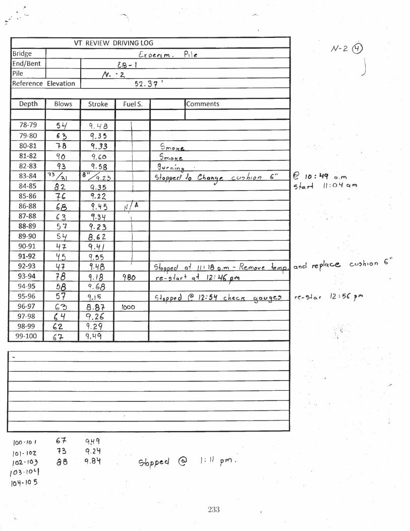
233

234

FDOT SUMMARY OF PILE DRIVINGOPERATIONS
235

Florida Department of Transportation
SUMMARY OF PILE DRIVING OPERATIONS
CARBON FIBER REINFORCED PILES
January 31, 2014
236

General:
On January 23rd and 24th 2014, two concrete piles reinforced with carbon fiber pre-stressing strands where driven at the SR 400/I-4 Widening from SR 44 to East of 95 project, at Bridge No. 790207 (Deer crossing) near Mile Post 127 in Volusia County. The piles were 24 inches in width and 100 feet in length and were driven at non production locations near Bent 3-1. Monitoring of the installation was performed with the use of Pile Driving Analyzer (PDA) and Embedded Data Collector (EDC) systems.
Pre-Stressed Concrete Piles:
The piles were cast on July 24th, 2013 and include 20 carbon fiber strands, 0.6 inches in diameter pulled to 39.45 kips of force, except at the corner locations where strands were pulled to 5 kips of force. From conversations with the Structures Laboratory, we understand the effective pre-stress after losses in the piles is 1,000 psi and the concrete strength was approximately 10,000 psi at the time of driving. Details of the reinforcement are included in Figures 1 and 2 below.
Figure 1 – Elevation
Figure 2 – Strand Details
237

Pile Driving Operations on Thursday January 23rd (Pile “N1”):
An APE D46-42 single acting diesel hammer with a ram weight of 10.1 kips was used by the Contractor to drive the piles on site. The hammer cushion consisted of two micarta plates of one inch in thickness each, placed between three layers of 0.5 inch thick aluminum plates for a total of 3.5 inches. To protect the head of the pile from impact an 8.75 inch thick pine plywood cushion was used for the initial 1308 blows. A second pile cushion of the same thickness was installed at that point which was compressed significantly and ignited towards the end of the drive. Pile cushion photographs are included in Figure 3.
The initial pile cushion experienced approximately 50 percent compression from its original thickness during the drive, and a slight eccentricity in the hammer strike was noted by the difference between the average stress (CSX), and the maximum stress recorded by an individual set of gages on one face of the pile (CSI) using the PDA system. No visible cracks were noted on the pile during this time. At approximate pile tip elevation -24 ft. pile driving was stopped to replace the pile cushion and remove the guide bars in the template, to allow continued driving without damaging the externally attached instrumentation. Upon resuming driving operations it was noted that the eccentricity on the strike had improved and a more even distribution of stress was recorded, as shown in Figure 4. The pile was subjected to a total of 2765 blows.
Figure 3 –Pile Cushions
238

Figure 4 – Average Stress (CSX) and maximum stress from instrumentation on one side of the pile (CSI)
Stress Limits:
Considering the reported concrete strength it became apparent that compression stresses would not control during the drive since the combination the available hammer and the local subsurface conditions would not allow the development of compression in excess of 6.25 ksi:
Maximum compressive stress (Section 455-5.11.2)
Sapc = [0.7(10000 psi) – 0.75(1000 psi)] / 1000 = 6.25 ksi
239

During the drive the stress recorded near the pile tip (CSB) was significantly lower than at the top of the pile (CSX), and neither approached 6.25 ksi, although CSX did exceed the typical limit used in production pile driving under the assumption of f’c = 6,000 psi and initial pre-stress of 1,000 psi (before losses), which yields a maximum allowed compression of:
Sapc = [0.7(6000 psi) – (0.75)(0.8)(1000 psi)] / 1000 = 3.6 ksi
Figure 5 - Top (CSX) and Tip (CSB) Compressive Stresses for Pile N1
Theoretical limit on tension stress:
Sapt = [3.25 (10000 psi)0.5 + 1.05(1000 psi)] / 1000 = 1.38 ksi
240

As shown in Figure 6, the theoretical limit on tension was exceeded (slightly) in portions of the drive between elevation -6.0 and -18.0 ft. without any visible cracking along the pile. As anticipated, high tensile stresses were induced as the pile tip entered a weaker layer in the profile, with SPT “N” blow count in the single digits and weight of hammer conditions.
Figure 6 – PDA Tension Stress and Soil Profile
Figure 7 provides a general picture of the estimated tension envelope along the pile at blow number 790 at approximate tip elevation -8.6 ft., indicating high tension values in the upper two-thirds of the object. It should be noted that production pile driving at this level of stress would not be continued without modifications (e.g., lower stroke, increased pile cushion) as it would be in violation of the Specifications.
241

Figure 7 – PDA Screen Capture and Tension Envelope
Pile Integrity:
In the PDA system the BTA parameter represents the percentage of pile cross section compared with the full cross section (PDA-W manual of operation, 2009). This parameter is obtained for every hammer strike, and provides a general picture of estimated pile integrity along the length of the object. Readings below 100% during the early portion of a drive, immediately after changes in pile cushion and at splice locations are not uncommon, however in this instance the latter portion of the drive where none of the above conditions existed did record slight decreases in BTA.
Relatively minor changes in BTA (in the neighborhood of 10%) can be the result of non-uniform resistance as the pile goes through layers of varying magnitudes of friction and could have caused the readings obtained by the PDA. The conservative assumption based on the proposed relationship between damage and BTA included in Figure 8, is that slight damage may have occurred near the pile tip beginning at blow number 2400 (approximate elevation -34.5 ft.), where the recorded BTA values went below 90%. As shown in Figure 8, the slight damage (87%) is estimated to have taken place at a depth of approximately 80 feet below the location of the instruments, or 15 feet above the pile tip as shown in Figure 9.
242

Figure 8 – BTA Parameter
Figure 9 – Wave-down / Wave-up Traces and Estimated Depth of Slight Damage (79.74’ below gauges)
243

The EDC system uses the “MPI” or Measured Pile Integrity parameter to check for damage to the pile during driving, and as with PDA it represents the ratio of pile impedance as described by Rausche and Goble, 1988. In addition, EDC makes use of the top and tip instrumentation to measure losses in pre-stress at the embedded gauge levels (two pile diameters from the head and one pile diameter from the tip). Anytime a change in measured strain reaches 50 micro-strain, the MPI is dropped to a value of 50, and would continue to drop as the loss of pre-stress increases. As an example, if the EDC calculates a drop in BTA to 88% and the measured strain at the pile tip changes by 50 micro-strain from its “zero” value, the reported MPI would be 100 – 12 – 50 = 38. As shown in Figure 10 the MPI value did indicate reductions along the drive, however it never reached or dropped below 50, suggesting no significant loss of pre-stress was measured. Note that EDC reports data in terms of “displacement” (i.e., depth below template) instead of elevation.
Based on the readings obtained from both PDA and EDC it can be concluded that the pile did not suffer any major damage during the drive in terms of integrity or pre-stress level, other than the observed spalling at the pile head during the last few hammer blows.
Figure 10 – EDC MPI Record (Green Line)
244

From top and tip instrumentation measurements obtained by EDC it is also possible to estimate the speed of the stress wave along the pile for every hammer strike, which provides some insight into possible development of micro-cracks during the drive. Although the EDC calculated wave speed has been known to behave erratically in some instances, in this drive it follows an expected trend that begins with a (rather large) value of approximately 14,600 ft/s, followed by a decrease to approximately 13,600 ft/s at a depth of 80 feet that is believed to be caused by the propagation of both vertical and horizontal micro-cracks within the pile.
As the pile enters the bearing layer, the final portion of the drive shows a relative increase of the wave speed to approximately 14,200 ft/s as the horizontal cracks close in compression and allow the wave to travel unimpeded, followed by a slight decrease towards the end of the drive. Although the calculated wave speeds appear to be larger than normal, the relative variations suggest the development of micro-cracks, which has also been observed in conventionally reinforced piles.
Figure 11 – Pile Resistance and EDC Estimated Wave Speed vs. Depth
245

Towards the end of the drive the second pile cushion was no longer capable of providing adequate protection and the concrete at the pile head spalled as shown in Figure 12. Driving was stopped at that point.
Figure 12 – Diesel Covered Pile with Spalled Sections
Pile Driving Operations on Friday January 24th (Pile “N2”):
Representatives from the Structures Laboratory and Central Office were not on site during pile driving operations on January 24th. It is our understanding that the only difference in driving for this pile was the use of a thinner pile cushion (6-inches) with the intent of subjecting the second pile “N2” to higher stress than “N1”. The Embedded Data Collector was not able to connect to the pile and therefore only PDA data is available.
Eccentricity of the hammer strike was recorded by PDA, and persisted with some improvement upon the subsequent two pile cushion changes as seen on Figure 13. As with the previous pile, the compressive stress delivered to the pile head did not approach the theoretical limit of 6.25 ksi, however it should be noted that the pile inspector’s log indicates that concrete spalled at the pile head immediately prior to the first change in cushion at approximate pile tip elevation -16.5 ft. It is possible that the continued hammering of the pile under eccentric loading with a thin pile cushion was the cause of the noted damage. No additional spalling was recorded in the field log.
246

Figure 13 – Average (CSX) and Maximum Compression Stress (CSI) at the Pile Top During the Drive
Figure 14 – Spalling near the Top of Pile N2
247
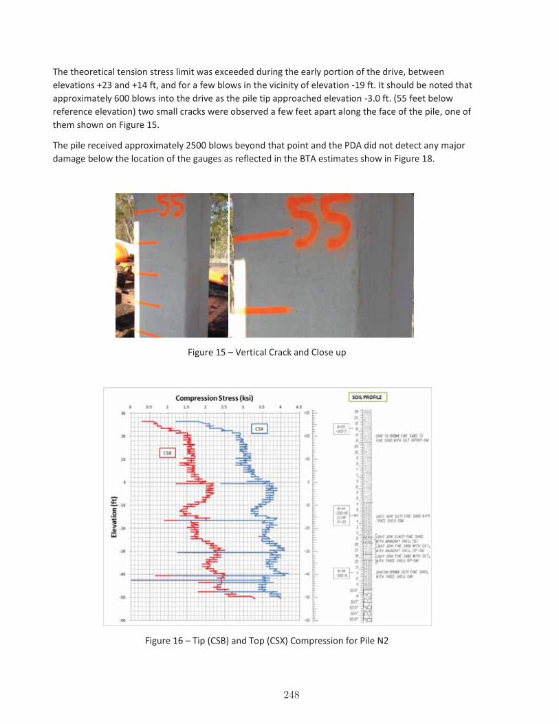
The theoretical tension stress limit was exceeded during the early portion of the drive, between elevations +23 and +14 ft, and for a few blows in the vicinity of elevation -19 ft. It should be noted that approximately 600 blows into the drive as the pile tip approached elevation -3.0 ft. (55 feet below reference elevation) two small cracks were observed a few feet apart along the face of the pile, one of them shown on Figure 15.
The pile received approximately 2500 blows beyond that point and the PDA did not detect any major damage below the location of the gauges as reflected in the BTA estimates show in Figure 18.
Figure 15 – Vertical Crack and Close up
Figure 16 – Tip (CSB) and Top (CSX) Compression for Pile N2
248

Figure 17 – Tension Stress on Pile N2
Figure 18 – PDA’s BTA Parameter for Pile N2
249

Pile Resistance:
The general subsurface profile presented layers of granular material with varying amounts of fines and shell overlying a Limestone formation that provided significant resistance, particularly during the end of drive for pile N2. At approximate elevations -29 and -49, pile resistance approached and exceeded the suggested driving resistance currently included in FDOT’s Structures Design Guidelines (i.e., 900 kips) for conventional pre-stressed piles 24-inches in width. It is interesting to note that although the suggested limit was exceeded by approximately 800 kips, overall the reinforcement performed well, with spalling occurring only near the pile head in both test piles under eccentric loading of the hammer strike. Figure 19 summarizes the resistance (pile capacity) recorded during both drives.
Figure 19 – Pile Resistance vs. Elevation
250

Summary:
� Two, 24 inch wide, 100 foot long pre-stressed concrete piles reinforced with Carbon Fiber strands were driven in Volusia County, Florida, on January 23rd and 24th 2014.
� Spalling at the pile head was observed on both piles, and was probably the result of slight eccentricities in the hammer strike under high stress blows with thinner than normal pile cushions. It is difficult to estimate whether similar damage would have occurred in conventional piles, however it is likely.
� The piles were monitored with the use of the Pile Driving Analyzer (PDA) and Embedded Data Collector (EDC) systems. No major damage was detected by the PDA on either pile, or the EDC in pile N1 (the system did not collect data for pile N2).
� Both PDA and EDC recorded data that can be interpreted as minor damage, particularly near the pile tip for pile N1. However the estimates, which could be the result of progressive aggravation of vertical and horizontal micro-cracks, were not accompanied by significant losses of pre-stress during the drive.
� Overall the piles had an acceptable performance under driving conditions that exposed them to high levels of stress throughout most of the drive, and received 2765 and 3139 hammer blows, respectively.
Rodrigo Herrera, P.E.
Asst. State Geotechnical Engineer
Florida Department of Transportation
251

APPENDIX F
MOMENT CAPACITY
CALCULATIONS
252

253

APPENDIX G
REPORT ON FIRST PILE CASTING
ATTEMPT
254

������������� ��������������
���������������
����
������������������������������
��������������������� �!"#�$%%&'%�
����������������������()��������
*�����
����'+&',-�,+',�
����������.�!/���0�����
�(12&�*2
��������� �3���������
4
255

����
�����������5�*��/�44
10th
Se
pte
mb
er,
Mo
nd
ay
• Th
e C
FCC
de
live
ry w
as
co
nfir
me
d.
• C
he
cke
d if
th
e d
eliv
ere
d m
ate
rials
we
re a
s p
er
ord
ere
d.
• 2
sta
tion
s fo
r in
sta
llin
g c
ou
ple
rs w
ere
se
t u
p, o
ne
at
ea
ch
en
d o
f th
e p
ile.
• Th
e s
pa
ce
pro
vid
ed
in t
he
typ
ica
l ste
el h
ea
de
rs
wo
uld
no
t b
e e
no
ug
h t
o fi
t g
rind
er f
or c
utt
ing
CFC
C
(ste
el i
s to
rch
ed
), s
o w
oo
de
n h
ea
de
rs w
ere
use
d
inst
ea
d.
• W
oo
de
n h
ea
de
rs o
f siz
e 2
4x24
in. w
ere
se
t u
p a
t e
ac
h o
f th
e p
ile e
nd
s. (
Ste
el h
ea
de
rs a
re n
orm
ally
u
sed
, bu
t th
ere
wa
s c
on
ce
rn a
bo
ut
da
ma
gin
g
stra
nd
s w
he
n p
ulli
ng
th
rou
gh
ste
el h
ole
s).
• It
wa
s n
ote
d t
ha
t th
e h
ole
s in
th
e w
oo
de
n h
ea
de
rs
we
re n
ot
smo
oth
. •
The
ho
les
in t
he
he
ad
er w
ere
co
rre
cte
d b
y g
rind
ing
. •
He
ad
ers
we
re p
osit
ion
ed
in a
pp
roxi
ma
te lo
ca
tion
s o
f p
ile e
nd
s. (
No
rma
lly t
he
y a
re a
ll p
ush
ed
to
de
ad
e
nd
so
str
an
ds
ca
n b
e fe
d t
hro
ug
h a
ll a
t sa
me
tim
e).
•
Ste
el s
tra
nd
s a
re u
sua
lly b
un
dle
d a
nd
pu
lled
th
rou
gh
fo
rms
with
fork
lift.
CFC
C s
tra
nd
s, h
ow
eve
r, w
ere
p
ulle
d t
hro
ug
h o
ne
at
a t
ime
. •
GA
TE in
sta
llers
no
ted
th
at
the
CFC
C s
tra
nd
s w
ere
lig
htw
eig
ht
an
d q
uic
k to
inst
all.
2 m
en
ea
sily
pu
lled
th
e s
tra
nd
s th
e 4
50-f
t le
ng
th o
f th
e p
ile b
ed
.
256

*��������*�����
�����
���4
• Th
e C
FCC
sp
irals
for e
ac
h p
ile
we
re p
lac
ed
in t
he
form
s.
• Th
e C
FCC
sp
oo
l wa
s m
ou
nte
d o
n
a ro
d a
nd
pla
ce
d in
lin
e w
ith t
he
b
ed
aft
er t
he
se
tup
wa
s c
he
cke
d
for c
orr
ec
t le
ng
th.
• Th
e C
FCC
str
an
ds
we
re in
sta
lled
in
th
e b
ed
. St
ran
ds
we
re c
ut
eve
ry 3
50 ft
. •
The
be
d le
ng
th w
as
me
asu
red
to
b
e 4
40 ft
. •
The
pro
du
ct
len
gth
wa
s m
ea
sure
d t
o b
e 3
29 ft
, wh
ich
in
clu
de
s h
ea
de
r ply
wo
od
th
ickn
ess
, 2 ¼
in. g
ap
in e
ac
h
he
ad
er,
an
d a
pp
rox.
1 ft
b
etw
ee
n h
ea
de
rs a
t p
ile e
nd
s.
257
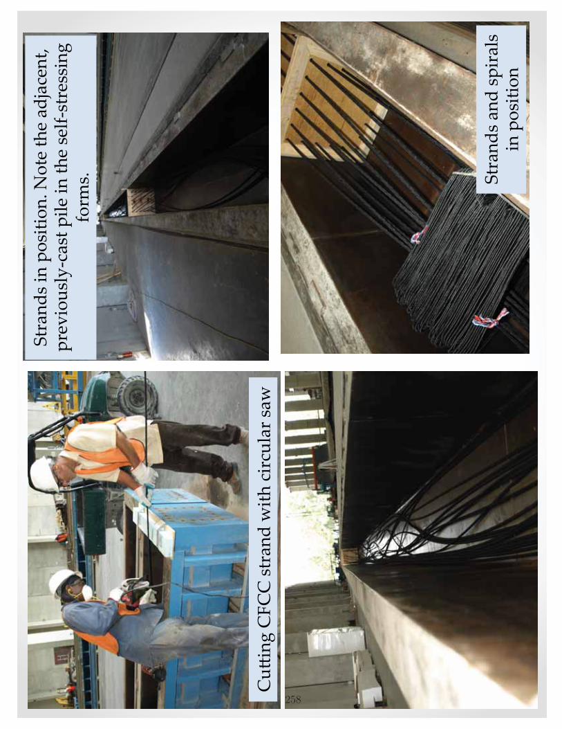
�/)
������
��������6��������/����6
4
*�����������������7�8
��������������-�
������/��.&������������������� &���������
���
�74
*����������������
�����������4
258

4411
th S
ep
tem
be
r, Tu
esd
ay
• Th
e c
ou
ple
rs w
ere
se
t u
p o
n b
oth
st
atio
ns.
•
A s
et
of m
ate
rials
req
uire
d t
o in
sta
ll 20
c
ou
ple
rs w
as
pla
ce
d o
n e
ac
h s
tatio
n.
• To
kyo
Ro
pe
de
mo
nst
rate
d t
he
co
up
ler
inst
alla
tion
pro
ce
du
re fo
r th
e fi
rst
co
up
ler.
• Th
e s
tee
l str
an
d w
as
inst
alle
d fr
om
th
e
live
en
d.
The
dire
ctio
n o
f tw
ist o
f th
e
ste
el s
tra
nd
ma
tch
ed
th
e C
FCC
str
an
d.
• O
ne
co
up
ler w
as
inst
alle
d b
y th
e F
AM
U-
FSU
gra
du
ate
stu
de
nts
.
• Th
e c
ou
ple
r in
sta
llatio
n w
as
the
n
co
ntin
ue
d b
y G
ATE
pe
rso
nn
el.
• A
wo
od
en
pla
tfo
rm w
as
pro
vid
ed
by
GA
TE in
ord
er t
o p
rovi
de
a w
ork
ing
su
rfa
ce
for t
he
inst
alla
tion
pro
ce
ss.
��/���������������4
259

��������������������������
�������4
9��:����/� ��4
�/)
���������������
�������������������:�
��/�������������
�����
������������4
��/�����
�����������
��������4
260

��/���������������4
• Th
e w
oo
de
n p
latf
orm
wa
s c
ha
ng
ed
to
ste
el a
fte
r a c
ou
ple
o
f in
sta
llatio
ns
for s
turd
ine
ss
du
ring
ha
mm
erin
g o
f co
up
ler
slee
ve.
• W
hile
co
up
ler s
lee
ves
we
re
be
ing
inst
alle
d, a
no
the
r cre
w
inst
alle
d m
esh
sh
ee
ts t
o t
he
st
ran
ds
to h
ave
th
em
rea
dy
for
the
co
up
lers
. •
Aft
er t
he
inst
alla
tion
on
th
e li
ve
en
d w
as
co
mp
lete
d, t
he
CFC
C
stra
nd
wa
s p
ulle
d m
an
ua
lly o
n
the
oth
er s
ide
to
rem
ove
an
y sla
ck
in t
he
ca
ble
. •
Co
up
lers
we
re s
tag
ge
red
by
ext
en
din
g t
he
CFC
C s
tra
nd
in 3
d
iffe
ren
t le
ng
ths
fro
m t
he
en
ds
of t
he
ou
ter p
iles.
Oth
erw
ise,
the
co
up
lers
wo
uld
no
t a
ll fit
in
the
cro
ss-s
ec
tion
vie
w.
261

*��������4
12th
Se
pte
mb
er,
We
dn
esd
ay
• Th
e fu
ll p
rest
ress
ing
forc
e w
as
to b
e 7
0% o
f u
ltim
ate
str
en
gth
(0.
70*0
.118
in2*
355k
si =
28.
9 k)
•
The
str
an
ds
clo
ser t
o t
he
jac
k w
ere
to
be
st
ress
ed
firs
t, t
o a
void
co
up
ler i
nte
rfe
ren
ce
d
ue
to
elo
ng
atio
n (
i.e.,
the
co
up
lers
ove
rlap
in
se
ctio
n v
iew
).
• O
ne
str
an
d w
as
pre
stre
sse
d t
o 7
kip
s (a
pp
rox.
25%
of t
he
full
pre
stre
ssin
g fo
rce
).
• A
sm
all
am
ou
nt
of s
lip w
as
ob
serv
ed
in t
he
C
FCC
str
an
d w
he
re it
exi
ted
th
e c
ou
ple
r. •
The
rem
ain
ing
str
an
ds
we
re s
tre
sse
d t
o 2
5%
of f
ina
l fo
rce
. •
Ma
rkin
gs
we
re m
ad
e o
n t
he
CFC
Cs
at
the
h
ea
de
r an
d a
t th
e c
ou
ple
r fa
ce
, to
m
ea
sure
elo
ng
atio
n a
nd
se
atin
g,
resp
ec
tive
ly.
• Th
e s
tee
l str
an
ds
on
th
e li
ve e
nd
we
re c
ut
ag
ain
, so
th
at
the
jac
k c
ou
ld
ac
co
mm
od
ate
th
e e
xpe
cte
d t
ota
l e
lon
ga
tion
.
262

*�������4
• A
fte
r th
e fi
rst
stra
nd
(#
15)
wa
s st
ress
ed
to
th
e fi
na
l fo
rce
, e
lon
ga
tion
wa
s m
ea
sure
d a
t th
e
jac
k. T
he
me
asu
red
elo
ng
atio
n
ma
tch
ed
we
ll w
ith t
he
th
eo
retic
al.
•
The
se
co
nd
str
an
d (
#13
) w
as
stre
sse
d t
o t
he
fin
al f
orc
e.
• W
hile
th
e ja
ck
wa
s a
bo
ut
to b
e
inst
alle
d o
n t
he
th
ird s
tra
nd
, th
e fi
rst
CFC
C s
tra
nd
slip
pe
d o
ut
of t
he
c
ou
ple
r with
th
e b
raid
ed
grip
an
d
me
sh s
he
et
still
att
ac
he
d t
o t
he
st
ran
d.
• D
ue
to
sa
fety
co
nc
ern
s, fu
rth
er
stre
ssin
g a
ctiv
itie
s w
ere
sto
pp
ed
. •
The
se
co
nd
str
an
d w
as
torc
h-c
ut
to
rele
ase
th
e t
en
sion
forc
e.
• Th
e c
utt
ing
an
d t
he
initi
al c
ou
ple
r fa
ilure
resu
lted
in d
am
ag
e t
o t
he
sp
irals
an
d a
lso m
ino
r da
ma
ge
to
th
e s
urr
ou
nd
ing
str
an
ds.
263

��������:��� ����*�����;'#�6������������������������ ����74
*�����;'<4
*�����;'#4
��������:��� ����*�����;'<����������/��� ���/����74
264

��������/�����(��.���4
• Th
e fa
iled
co
up
ler w
as
take
n in
th
e G
ATE
off
ice
for
furt
he
r in
spe
ctio
n.
• Th
e c
ou
ple
rs fr
om
th
e t
orc
h-c
ut
stra
nd
(a
nd
also
th
e
4 c
ou
ple
rs fr
om
th
e p
rac
tice
inst
alla
tion
at
the
FD
OT
Lab
on
Ma
y 18
) w
ere
dism
an
tled
usin
g a
de
vic
e
fro
m T
oky
o R
op
e.
• Th
e c
ou
ple
rs w
ere
rem
ove
d fr
om
th
e c
ast
ing
be
d.
Eac
h c
ou
ple
r ha
d a
pp
rox.
3 ft
of C
FCC
str
an
d
ext
en
din
g fr
om
it.
• To
kyo
Ro
pe
to
ok
the
faile
d c
ou
ple
r, a
lon
g w
ith t
he
m
ajo
rity
of t
he
oth
er c
ou
ple
rs, t
o t
he
ir R
&D
off
ice
for
furt
he
r in
spe
ctio
n.
265
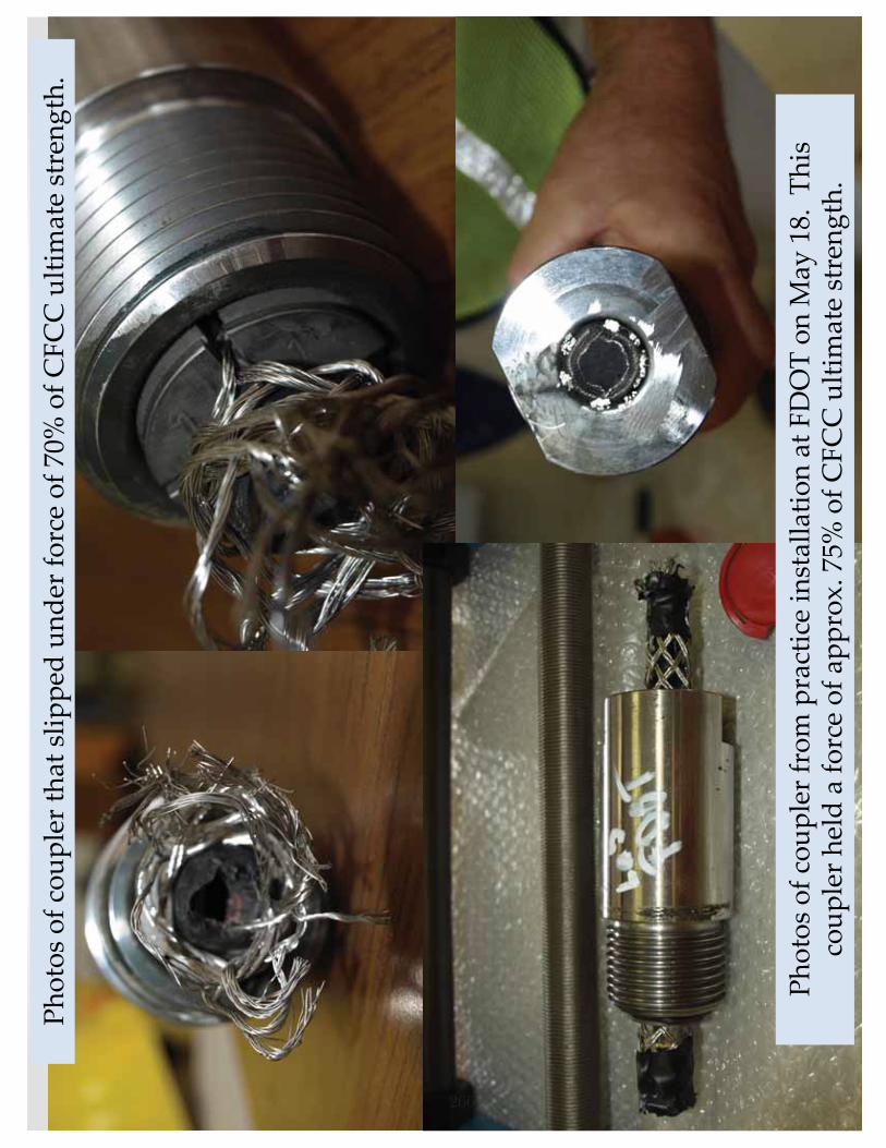
�������� ���/����� ���
������������������������������1.�'"7�������
��/������
����� ������ �����=7�%<>
�� ��
����/��������������74
�������� ���/�����������������/����� ������ �%+>
�� ��
����/��������������74
266

APPENDIX H
PHOTOS
267

PILE SPECIMEN PRODUCTION
268

Figure H.1: Spool of CFCC strand
Figure H.2: Steel header used for a conventional steel-prestressed con-crete pile (Replaced by wooden header for this research
269
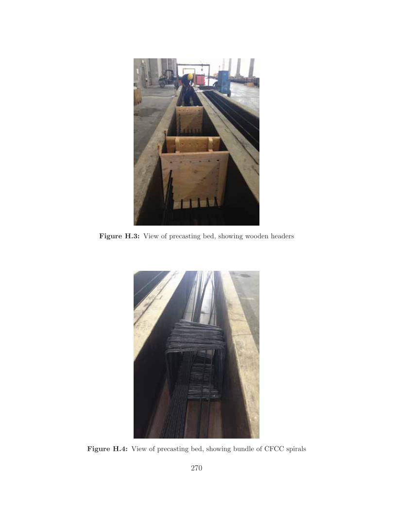
Figure H.3: View of precasting bed, showing wooden headers
Figure H.4: View of precasting bed, showing bundle of CFCC spirals
270

Figure H.5: Casting bed with wooden headers and installed CFCCstrands
Figure H.6: Couplers, before installation
271

Figure H.7: CFCC wedges sprayed with Molybdenum Disulfide
Figure H.8: CFCC coupler installation: wrapping the CFCC strandwith mesh
272

Figure H.9: CFCC coupler installation: installing braid grip on CFCCstrand
Figure H.10: CFCC coupler installation: placing wedges on mesh-wrapped CFCC strand
273

Figure H.11: CFCC coupler installation: marking wedges to preparefor pushing
Figure H.12: CFCC coupler installation: coupler in jacking system,ready for pushing
274

Figure H.13: CFCC coupler installation: pushing wedges into couplerwith jacking system
Figure H.14: CFCC coupler installation: ready to screw two parts to-gether
275

Figure H.15: CFCC coupler installation: screwing two parts together
Figure H.16: CFCC coupler installation: partially-completed couplers,showing 3 stages of installation
276
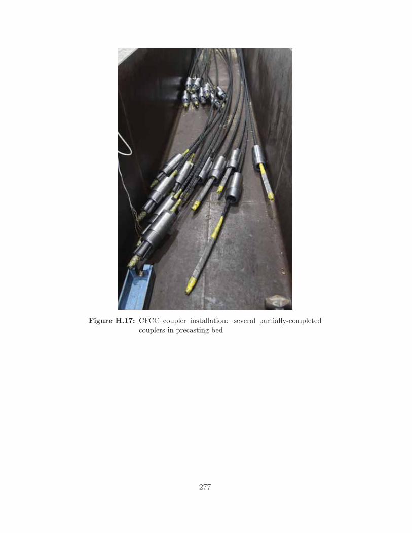
Figure H.17: CFCC coupler installation: several partially-completedcouplers in precasting bed
277

Figure H.18: CFCC coupler installation: showing several couplers incasting bed
Figure H.19: Partial installation of several couplers
278

Figure H.20: Stressing end of self-stressing casting bed
Figure H.21: Non-stressing end of self-stressing casting bed
279

Figure H.22: CFCC spirals zip-tied to strands
Figure H.23: Lifting loops
280

Figure H.24: Showing staggered couplers, with CFCC strands alreadystressed, looking from stressing end
Figure H.25: Showing staggered couplers and close-up of coupler, withCFCC strands already stressed
281

Figure H.26: CFCC strands, spirals, and wooden headers in position;ready to cast
Figure H.27: Casting piles using self-consolidating concrete
282

Figure H.28: Strain gages S301 - S314
Figure H.29: Strain gages S320 - S326
283
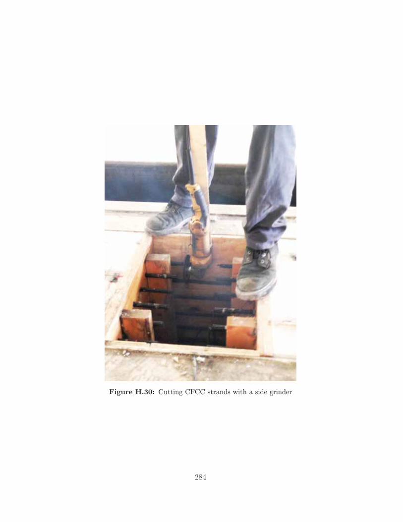
Figure H.30: Cutting CFCC strands with a side grinder
284

PILE DRIVING PHOTOS
285

Figure H.31: End bent 3-1 on westbound bridge; Two 100-ft piles readyto be driven
Figure H.32: Smoke during Pile 1 driving
286

Figure H.33: Charred pile cushion, after Pile 1 driving
Figure H.34: Concrete spalling on head of Pile 1 after being driven
287

Figure H.35: Leaked diesel and concrete spalling on head of Pile 1 afterbeing driven
Figure H.36: Smoke during Pile 2 driving
288

Figure H.37: Concrete spalling on head of Pile 2 during driving
Figure H.38: Horizontal (tension) crack in Pile 2
289

Figure H.39: Horizontal (tension) crack in Pile 2, on other side
290