investigation of a multi-ball, automatic dynamic balancing
TRANSCRIPT

Investigation of a multi-ball, automaticdynamic balancing mechanism for
eccentric rotors
BY K. GREEN*, A. R. CHAMPNEYS, M. I. FRISWELL AND A. M. MUNOZ†
Bristol Laboratory for Advanced Dynamics Engineering, University of Bristol,Queen’s Building, University Walk, Bristol BS8 1TR, UK
This paper concerns an analytical and experimental investigation into the dynamics ofan automatic dynamic balancer (ADB) designed to quench vibration in eccentric rotors.This fundamentally nonlinear device incorporates several balancing masses that are freeto rotate in a circumferentially mounted ball race. An earlier study into the steady stateand transient response of the device with two balls is extended to the case of an arbitrarynumber of balls. Using bifurcation analysis allied to numerical simulation of a fullynonlinear model, the question is addressed of whether increasing the number of balls isadvantageous. It is found that it is never possible to perfectly balance the device atrotation speeds comparable with or below the first natural, bending frequency of therotor. When considering practical implementation of the device, a modification issuggested where individual balls are contained in separate arcs of the ball race, with rigidpartitions separating each arc. Simulation results for a partitioned ADB are comparedwith those from an experimental rig. Close qualitative and quantitative match is foundbetween the theory and the experiment, confirming that for sub-resonant rotationspeeds, the ADB at best makes no difference to the imbalance, and can make thingssubstantially worse. Further related configurations worthy of experimental andnumerical investigation are proposed.
Keywords: Jeffcott rotor; imbalance; autobalancer; bifurcation; vibro-impact;multistability
On
*ABoe†PrDes
1. Introduction
Imbalance in rotating machinery is a common source of vibration in manyapplications. Owing to the centre of mass of the rotating component not beinglocated at the centre of rotation, such eccentric rotors undergo periodicoscillation known as whirl (Jeffcott 1919). To limit this vibration, rotors aretypically balanced by either using fixed static masses added to the rotor, orconversely by machining away small mass from the rotor, during the
Phil. Trans. R. Soc. A (2008) 366, 705–728
doi:10.1098/rsta.2007.2123
Published online 18 October 2007
e contribution of 8 to a Theme Issue ‘Experimental nonlinear dynamics I. Solids’.
uthor and address for correspondence: Theoretical Physics, FEW, Vrije Universiteit, Delelaan 1081, 1081HV Amsterdam, The Netherlands ([email protected]).esent address: Escuela Tecnica Superior de Ingenieros, University of Seville, Camino de loscubrimientos s/n, Sevilla 41092, Spain.
705 This journal is q 2007 The Royal Society
K. Green et al.706
manufacturing process. However, such balancing cannot compensate for changesin imbalance that occur post-production or as a result of operating conditions.Thus, frequent field balancing is required in many applications. Furthermore,this addition (subtraction) of static mass cannot account for a dynamicimbalance. One example of a dynamic imbalance is found in a washing machine,i.e. one cannot predict, a priori, where the washing will accumulate during thewash cycle (Adolfsson 2001).
Such dynamic imbalance has inspired the use of self-compensating, automaticdynamic balancing (ADB) mechanisms for eccentric rotors. The principal ideabehind the ADB is that the balancing balls are subjected to a driving forcecaused by an apparent centripetal force acting from the offset centre of mass toeach ball. When the speed of rotation is below the first resonance, this drivingforce pushes the balls towards the imbalance, thus moving the centre of massaway from the centre of rotation. However, when the speed of rotation is greaterthan the first resonance, the driving force pushes the balls to the opposite side ofthe rotor than the imbalance, thus moving the centre of mass towards the centreof rotation. Viscous damping in the ball race causes energy dissipation, allowingthe balls to come to rest in asymptotically stable steady-state positions.
The ADB first received attention as early as 1904, with the first theoreticalinvestigation, accompanied by some experiments, undertaken by Thearle (1932).In this paper, there is also a discussion on why an ADB consisting of a fluid, inplace of solid weights, would not work. Further theoretical investigations can befound in Sharp (1975) and Majewski (1987), in which the results of a linearstability analysis show that complete balance is possible for sufficiently highrotation speeds. Moreover, Ryzhik et al. (2004a) showed that even if partialbalance can only be achieved, an ADB increasingly reduces vibration as therotation speed is increased. There are several commercial implementations ofADBs, with a number of patents granted from 1961 onwards (see Lee & VanMoorhem 1996). Applications include optical disc drives, in which the aim is toachieve higher operating speeds without losing tracking performance (Kim &Chung 2002; van de Wouw et al. 2005), and balancing of machine tools, such aslathes, angle grinders and cutting tools (Rajalingham & Rakheja 1998).However, the ADB idea has not been more generally adopted, not least becausethe problem is fundamentally nonlinear, and is extremely sensitive toperturbation. Thus, while the ADB can completely quench whirl oscillations atsome rotation speeds and for some initial conditions, it can also make theimbalance significantly worse.
Only recently have fully nonlinear analyses of the autobalancer beenundertaken. Based on a Lagrangian description of the equations of motion,steady-state bifurcation studies were carried out by Chung & Ro (1999) and byAdolfsson (2001), who identified regions in parameter space where stablerotating states, whether balanced or not, are possible. By moving to a rotatingframe, Green et al. (2006a) carried out a detailed nonlinear investigation in thecase of two balls, by computing both isolated branches of periodic solutions andthose emanating from Hopf bifurcations of the equilibrium states. Significantregions of bistability were found between these steady and periodic states,chaotic states and states in which the balls rotate at a different angularfrequency than the rotor. Furthermore, perturbations were shown to result in alarge growth in the vibration before subsequent transient decay. This prompted
Phil. Trans. R. Soc. A (2008)
707Multi-ball automatic dynamic balancer
the study by Green et al. (2006b), where the authors used the concept ofpseudospectra to analyse this sensitivity to perturbation. It was found therethat while the completely balanced state becomes increasingly stable for highrotation frequencies, it also becomes increasingly sensitive to perturbation, withan increasingly larger transient response before settling to the steady state.
Experimental investigations into the use of ADBs can be found in Lee & VanMoorhem (1996), Huang et al. (2002) and van de Wouw et al. (2005). One of thecrucial issues is to design a releasing mechanism for the balancing masses thatovercomes a global instability identified in Green (2005), in which the constantspeed of the balancing masses lags that of the rotor. This may be partiallyovercome by clamping the balls in fixed positions until the desired, constantspeed of rotation is reached. The balls could then be released at the same speedas the rotor. van de Wouw et al. (2005) investigated a different mechanism withmany balls in which the energy is dissipated through frictional forces between theballs and the race, which encourages the balls to remain approximately in phasewith the rotor. However, a non-zero force is produced when the balls come torest. Consequently, the steady-state positions are not discrete but instead arefound over small ranges of the race. This phenomenon is known as stiction. Thus,compared to the viscous damping case, this multiplicity of equilibria is harder toanalyse and is more likely to produce a non-zero radial vibration when the ballscome to rest.
The aim of this paper is to look at the practical issues associated with animplementation of the ADB on a large-scale rotor. We first consider the effect ofusing more than two balancing masses. In particular, we show how the stabilityregions found in Green et al. (2006a) for the two-ball case change for three andfour balls. We have also designed and built an experimental rig inspired by someof the previous experimental results. To overcome some of the observedinstabilities, we propose a novel design consisting of a partitioned ball race.However, for our chosen design, we found that the dramatic increase in radialvibration meant that it was not practically possible to break through the firstresonance. This setback was also identified in Lee & Van Moorhem (1996).Therefore, in this paper, our experimental investigations will be confined to thecase of low rotation speeds.
The rest of the paper is organized as follows. In §2, we recall the equations ofmotion derived by Green et al. (2006a) of an eccentric rotor fitted with an ADBconsisting of an arbitrary number of balancing balls. From direct analysis of theequations, we identify all possible steady-state solutions, whether balanced ornot, and show that the balanced state has a translational degeneracy for morethan two balls. Next, in §3 we perform a full nonlinear bifurcation analysis foran ADB with three and four balancing balls, mapping out regions of stableequilibria as parameters in the problem are varied. This is complemented bysimulation results obtained by numerical integration. In §4, we introduce thepartitioned ball race model and show the results of numerical simulations. In§§5 and 6, we describe our experimental set-up and present results which arecompared with numerical simulation results for the corresponding parametervalues, where only the experimental viscous damping coefficient has to beidentified through fitting. Finally, in §7 we draw conclusions and suggestavenues for future work.
Phil. Trans. R. Soc. A (2008)

0
k
a
f2
f1f3
e
wk CM
CR
D
Pf1
Pb1
Pb3
Pf3
Pf2
Pb2
c
c
Y
X
Figure 1. Schematic of an automatic dynamic balancer with a partitioned race (see text forexplanation of symbols).
K. Green et al.708
2. Automatic dynamic balancer
An automatic dynamic balancer consists of two or more balancing masses (balls)that are free to move in a ball race that is mounted at a fixed radial distance Rfrom the centre of rotation of a rotor. A rotating disc with an eccentric masscentre, fitted with a partitioned ADB is shown schematically in figure 1 for thecase of three balls, where for the time being we shall ignore the presence of theboundaries between partitions Pfi;bi (iZ1, 2, 3).
The race is positioned at a fixed distance from the centre of rotation of the discand contains a small amount of viscous fluid. The point CM represents the centreof mass of the disc without the balancing masses. It is located at a distance(eccentricity) 3 from the centre of rotation CR. The whole rig (rotor plus ADB) isassumed to be isotropically suspended and to rotate at a constant angularvelocity u. For a study into anisotropic support, we refer to Ryzhik et al. (2004b).Furthermore, all movement is assumed to be constrained to the horizontal(X, Y )-plane, and due to centrifugal forces, the balls are assumed to remain incontact with the race.
(a ) Equations of motion
The equations of motion describing the ADB can be derived using aLagrangian approach, with generalized coordinates,
ðX ;Y ;f1;f2; :::;fnÞ; ð2:1Þdescribing the motion of the rotor in the (X, Y)-plane and the angular position ofthe i th ball, respectively. With the addition of a simple Rayleigh dissipationfunction representing directly proportional viscous damping in both the ball race
Phil. Trans. R. Soc. A (2008)
709Multi-ball automatic dynamic balancer
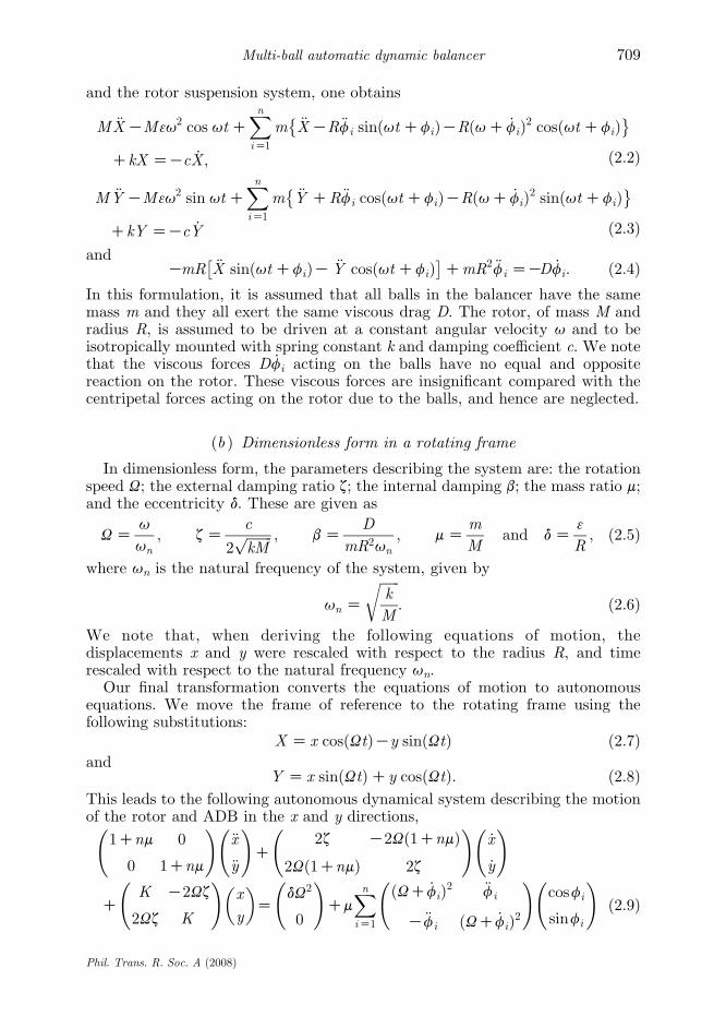
and the rotor suspension system, one obtains
M €XKM3u2 cos utCXniZ1
m €XKR€fi sinðutCfiÞKRðuC _fiÞ2 cosðutCfiÞ� �
CkX ZKc _X ; ð2:2Þ
M €YKM3u2 sin utCXniZ1
m €Y CR€fi cosðutCfiÞKRðuC _fiÞ2 sinðutCfiÞ� �
CkY ZKc _Y ð2:3Þand
KmR €X sinðutCfiÞK €Y cosðutCfiÞ� �
CmR2 €fi ZKD _fi: ð2:4ÞIn this formulation, it is assumed that all balls in the balancer have the samemass m and they all exert the same viscous drag D. The rotor, of mass M andradius R, is assumed to be driven at a constant angular velocity u and to beisotropically mounted with spring constant k and damping coefficient c. We notethat the viscous forces D _fi acting on the balls have no equal and oppositereaction on the rotor. These viscous forces are insignificant compared with thecentripetal forces acting on the rotor due to the balls, and hence are neglected.
(b ) Dimensionless form in a rotating frame
In dimensionless form, the parameters describing the system are: the rotationspeed U; the external damping ratio z; the internal damping b; the mass ratio m;and the eccentricity d. These are given as
UZu
un
; zZc
2ffiffiffiffiffiffiffiffikM
p ; bZD
mR2un
; mZm
Mand dZ
3
R; ð2:5Þ
where un is the natural frequency of the system, given by
un Z
ffiffiffiffiffiffik
M
r: ð2:6Þ
We note that, when deriving the following equations of motion, thedisplacements x and y were rescaled with respect to the radius R, and timerescaled with respect to the natural frequency un.
Our final transformation converts the equations of motion to autonomousequations. We move the frame of reference to the rotating frame using thefollowing substitutions:
X Z x cosðUtÞKy sinðUtÞ ð2:7Þand
Y Z x sinðUtÞCy cosðUtÞ: ð2:8ÞThis leads to the following autonomous dynamical system describing the motionof the rotor and ADB in the x and y directions,
1Cnm 0
0 1Cnm
!€x
€y
!C
2z K2Uð1CnmÞ2Uð1CnmÞ 2z
!_x
_y
!
CK K2Uz
2Uz K
!x
y
� �Z
dU2
0
!Cm
XniZ1
ðUC _fiÞ2 €fi
K€fi ðUC _fiÞ2
!cosfi
sinfi
!ð2:9Þ
Phil. Trans. R. Soc. A (2008)

K. Green et al.710
and the motion of the ith ball,
€fiCb _fiKð€xKU2xK2U _yÞsinfiCð€yKU2yC2U _xÞcosfiZ0; ð2:10Þwhere fi measures the angular position of the ith ball from the line of eccentricity(CR–CM in figure 1), iZ1,., n. Furthermore, KZ1KU2ð1CnmÞ represents theeffect of centripetal acceleration. This reduces the effective stiffness of the systemand is often called ‘spin softening’ or ‘centripetal softening’. For a full derivation,including the procedure of making these equations dimensionless, we refer toGreen et al. (2006a).
(c ) Steady-state analysis
Green et al. (2006a) provides a detailed bifurcation analysis of steady statesand periodic solutions found in an ADB with two balancing balls. In this paperwe consider an ADB with three and four balls showing how this affects thepotential stability of the system.
The steady-state solutions are obtained by setting the time derivatives in (2.9)and (2.10) as zero. The steady-state solution can be categorized as balancedwhen rZ
ffiffiffiffiffiffiffiffiffiffiffiffiffiffiffix2Cy2
pZ0 or unbalanced when rZ
ffiffiffiffiffiffiffiffiffiffiffiffiffiffiffix2Cy2
ps0 but the balls come
to rest.A balanced steady state corresponds to the centre of mass of the system being
located at the centre of rotation, and satisfies
x Z y Z 0;XniZ1
cos fi ZKd
mand
XniZ1
sin fi Z 0: ð2:11Þ
When nO2, there exist infinitely many solutions to (2.11). We will refer to thesesolutions as the sets of balanced state 1.
As is the case for two balls, unbalanced steady states are found when
y
xZ tan fi; i Z 1;.;n; ð2:12Þ
with solutions
fi Zf1 Ckip; i Z 2;.;n; ki 2Z: ð2:13ÞWithout loss of generality, we consider kiZ0 or 1. When kiZ0, the first and theith ball coincide and when kiZ1, the first and the ith ball are found on oppositesides of the race to each other, in line with the centre of rotation CR. We notethat in this analysis, collisions between balls are neglected. Physically, this couldbe realized by considering a multiple ball race (Hwang & Chung 1999).
When all balls coincide (kiZ0), solutions, in terms of f1, are
x ZKU2ðnm cos f1CdÞC2nmU3z sin f1
K2 Cð2UzÞ2
and
y ZnKmU2sinf1K2UzðdU2 CnmU2cosf1Þ
K2 Cð2UzÞ2;
9>>>>>>>>=>>>>>>>>;
ð2:14Þ
Phil. Trans. R. Soc. A (2008)

711Multi-ball automatic dynamic balancer
where
f1 ZGarccosK2nmUz
d
ffiffiffiffiffiffiffiffiffiffiffiffiffiffiffiffiffiffiffiffiffiffiffiffiffiffiffiK2 Cð2UzÞ2
q0B@
1CAKarctan
KK
2Uz
� �; fi Zf1; i Z 2;.; n:
ð2:15ÞIn what follows, we will refer to (2.14) and (2.15) as the coincident state 2G.
When (nKm) balls lie opposite from m coincident balls (kiZ1 for some i ), wefind solutions
x ZKU2ðð2mKnÞm cos f1CdÞC2ð2mKnÞmU3z sin f1
K2 Cð2UzÞ2
and
y Zð2mKnÞKmU2sinf1K2UzðdU2 Cð2mKnÞmU2cosf1Þ
K2 Cð2UzÞ2;
9>>>>>>>>=>>>>>>>>;
ð2:16Þ
where
f1 ZGarccosK2ð2mKnÞmUz
d
ffiffiffiffiffiffiffiffiffiffiffiffiffiffiffiffiffiffiffiffiffiffiffiffiffiffiffiK2 Cð2UzÞ2
q0B@
1CAKarctan
KK
2Uz
� �; fi Zf1;
i Z 2;.;m; fj Zf1 Cp; j ZmC1;.; n:
ð2:17Þ
In what follows, we will refer to (2.16) and (2.17) as the (nKm) in-line states3(nKm)G.
Again, we refer to Green et al. (2006a) for an analysis of two balls, i.e. nZ2and consequently, in (2.16) and (2.17), mZ1. Here we consider three and fourbalancing balls.
For nZ3, we can either have mZ1 or 2. However, as the balls are identical soare these states, i.e. at any one time we have one separate and two coincident balls.The sign of (2.17) determines the region where the separate (or the coincident)ball(s) are with respect to the imbalance. Hence we refer to the in-line states, withthree balls, simply as 3G.
For nZ4, we have three situations, one where two balls are coincident (mZ2)and one where three balls are coincident (mZ3). (The latter state being identicalto mZ1.) We will refer to these four-ball, in-line states as 3A and 3BG,respectively.
(d ) Conditions for existence of steady states
Analogous to the two-ball case, (2.11) implies that, for a balanced state 1 to exist,
mRmcdd
n: ð2:18Þ
In other words, to achieve balance, the combined mass of the balls must be largeenough to cope with the eccentricity d. Note that when equality is reached, thiscorresponds to the coincident states 2G.
Phil. Trans. R. Soc. A (2008)

K. Green et al.712
The coincident states 2G exist only if the modulus of the argument of theinverse cosine of (2.15) is less than unity, i.e.
K2Oð2UzÞ2 nm
d
� 2K1
� �: ð2:19Þ
As for the two-ball case, when m!mc, the states 2G always exist.Likewise, from (2.17), the in-line states 3(nKm)G exist if
K2Oð2UzÞ2 ð2mKnÞmd
� �2
K1
� �: ð2:20Þ
In other words, they exist for m!dð2mKnÞ.The existence of the coincident and the in-line states, above the critical values
of m, depends on the other parameters d, z and b in a non-trivial way. Toinvestigate this, we turn to numerical bifurcation techniques.
3. Numerical results for multiple balls
In this section we investigate the stability of the steady states identified in §2cusing numerical bifurcation techniques. Namely, we compute the boundariesbetween solutions with differing stability using the continuation packageMATCONT (Dhooge et al. 2004). In this way, a detailed map is produced showinghow regions of stability change as parameters are varied. These results will bebacked up by direct simulation of the equations of motion.
In each case, where appropriate, the fixed parameters are given as
bZ dZ zZ 0:01 and mZ 0:05: ð3:1ÞThese parameters were chosen to allow direct comparison with the two-ball ADBstudy of Green et al. (2006a).
(a ) Steady-state bifurcation diagram for nZ3
We start by investigating the ADB with three balancing balls. Figure 2a–dshows two-parameter bifurcation diagrams forU versus m, d, z and b, respectively.The dark shaded regions of figure 2 indicate regions of parameter space in whichthe balanced state 1 is stable. The lighter shaded regions correspond to parametersat which one of the coincident states 2G is stable. The unshaded regionscorrespond to regions of instability. Solid lines correspond to bifurcations of states1 and 2G, while dashed lines correspond to bifurcations of states 3G. The curvesare labelled as Hopf bifurcations ‘H’ (oscillatory instabilities) which occur when apair of pure imaginary eigenvalues cross the imaginary axis and saddle-nodebifurcations ‘SN’ (steady-state instabilities), which due to symmetry are actuallypitchfork bifurcations for some of the states. In the latter case, a real eigenvaluecrosses the imaginary axis (Kuznetsov 1997). Furthermore, as there are infinitelymany balanced states, we fix f3Zp when analysing the bifurcations of state 1.This is equivalent to computing bifurcations of state 1 for the two-ball case with adifferent d to that used by Green et al. (2006a). Likewise, the coincident states maybe compared to a two-ball case where the masses of the balls are increased, andthe in-line states to the case where each ball has a different mass.
Phil. Trans. R. Soc. A (2008)

(a)
d
W
SN2±
SN3±
SN3±
SN3±
SN2±
H3–
0.08 0.15
0.10
0.05
0 1 2 3
W0 1 2 30 1 2 3
0.06
0.04
0.02
0
0.10 0.5
0.4
0.3
0.2
0.1
0.08
0.06
0.04
0.02
0.5 1.0 1.5 2.0 2.5W
m
H3–
H2–
H3–
H3–
H3– H3+
H3–
H3+
H2–
H1H1
H3+
H3+
H1
H1
H1
PF1, 2–PF1, 2+
SN2±
SN2±
SN3±
H3–
H3–
H3+
H2–
H1
H1
H1
H3–H3+
b
W
SN2± SN2±
SN3± H3+H3–
H2–
H1
H1 H2–
H1
H3–
H3+
(b)
(c) (d )
z
Figure 2. Two-parameter bifurcation diagrams of steady-state solutions in the three-ball ADB.(Solid lines, saddle-node bifurcations SN and Hopf bifurcations H of states 1 and 2G; broken lines,bifurcations of state 3; dark shaded regions, stable state 1; lighter shaded regions, stable state 2K.)Whenfixed, the parameters arebZdZzZ0.01 andmZ0.05.The varying parameters are (a)U versusm,(b) U versus d, (c) U versus x and (d ) U versus b.
713Multi-ball automatic dynamic balancer
It is clear from these bifurcation diagrams that for low rotation speeds thecoincident states 2G are stable. Specifically, it can be shown that this is state 2K.While for high rotation speeds the balanced state 1 is shown to be stable.Furthermore, figure 2b shows a region of stability, for high eccentricity d, of thebalanced state 1, close to the resonant rotation speed UZ1. This is our firstindication that the addition of more balancing balls changes the stabilityproperties. We recall that in Green et al. (2006a), the two-ball ADB was shownto exhibit a small region of stability close to this resonant speed in all parameterplanes. Moreover, it was shown that this small region of stability was accessibleonly through a very limited range of initial conditions. In other words, forintermediate rotation speeds, and random initial conditions, the system is likelyto be drawn into unstable, possibly chaotic dynamics. However, the three-ballADB shows less stability close to the resonant speed, for the parameter rangeunder consideration. Finally, in the (U, m)-plane and for low values of m, thecoincident states 2G are stable. Again, it can be shown that this is state 2K.
Phil. Trans. R. Soc. A (2008)

K. Green et al.714
Moreover, for each of the parameter sets under consideration, and startingwithin a region of balanced equilibrium (dark shading), the following scenarioholds: for decreasing U, the balanced state 1 is destabilized in a Hopf bifurcationH1. The dynamics then enter a region of non-steady-state behaviour, containingperiodic oscillations through to chaotic motion. Decreasing U further sees asaddle-node bifurcation SN2G. At this point, the two coincident states 2G areborn. Again, we have that the state 2K is stable, while the state 2C is unstable.
Figure 2c shows that the region of stability of the balanced state 1 in the (U, d)-plane is small. This is again in stark contrast with the two-ball case, in which thisregion of stability was seen to cover approximately half of the parameter planeunder consideration. This shows that increasing the number of balancing masseshas a detrimental effect on whether or not stability can be achieved for the range ofparameters under consideration. Physically, this implies that the three-ball ADBcannot achieve balance when the rotor damping z is too high. We note that thebifurcation diagram in the (U, b)-plane is practically identical to the two-ball case.
Like the two-ball case, the states 3Gwere found to be always unstable. However,it is involved in an interesting bifurcation scenario. Figure 3a–c shows one-parameter bifurcation diagrams, for the three-ball ADB, for mZ0.05, 0.005 and0.0025, respectively, i.e. for an increasing rotor mass to ball mass ratio. For large m,figure 3a shows that the four states 2G and 3G are born in two separate saddle-nodebifurcations. These occur at the left and right edges of the ‘v’-shaped curves SN2Gand SN3G, as shown in figure 2a. Decreasing m sees one pass the base of the ‘v’representing the saddle-node curve SN3G while still inside the v-shaped curveSN2G (figure 2a). Figure 3b shows a one-parameter transition at such a value of m,namely mZ0.005. It is clear that the two sets of states 2G are still born in twoseparate saddle-node bifurcations SN2G. However, the two sets of states 3G havenow merged into two curves; a lower curve on which one finds the state 3C and anupper curve on which one finds the state 3K. The states 3G now exist for all U.Finally, figure 3c shows that by decreasing m further to mZ0.0025 we pass the baseof the ‘v’ representing the saddle-node curve SN2G (again see figure 2a). Similar tothe case for the states 3G, the sets of states 2Gmerge together. They form an uppercurve consisting of state 2K and a lower curve consisting of state 2C. Subsequently,for low values of m, both the states 2G and 3G exist for all U.
(b ) Steady-state bifurcation diagram for nZ4
Figure 4a–d shows two-parameter bifurcation diagrams for the four-ball ADB.The notation used is the same as for the three-ball diagrams of figure 2. Theexception being that the in-line state 3 now comes in two varieties: 3A and 3BG
(recall §2c). Again, as there are infinitely many balanced states 1, we fix f3Zp andf4ZKp when computing bifurcations of state 1. Once more, the balanced state 1 isshown to be stable for high rotation speeds, while the coincident state 2K is stable forlow rotation speeds or low mass ratios m. Interestingly, however, the region ofstability around the resonant speed (UZ1), identified for the two-ball ADB inGreenet al. (2006a) but shown to disappear for the three-ball ADB in figure 2a, reappearsfor the four-ball ADB. In fact, figure 4b shows that this region of stability now occursfor both low and high values of d. It is clearly seen that all regions of stability of state1 are connected to the Hopf curve H1. (In fact, the regions of stability of state 1 areconnected by this curve for large values of m in figure 4a–d.)
Phil. Trans. R. Soc. A (2008)

–1
0
1
2
3
4
5
6
7
2
+
2
+
2
–
2
–3
+
3
+
3
–
3
–
f1
–1
0
1
2
3
4
5
6
7
f1
H3– H3– H3–
H2–
H1 H1 H1
H3+ H3+
SN3± SN2±
SN2± SN3±
(a)
(c)
(b)
1 1
0.5 1.0 1.5 2.0 2.5W
0.5 1.0 1.5 2.0 2.5W
0.5 1.0 1.5 2.0 2.5W
2
–
2
–
3
–
3
–
3
+
3
+
3
+2
+
2
+
SN2±
SN2±
H3 H3
H1
H3–
H2–
1 1
2
+
2
–3
–
2
–
3
–
3
+
2
+
3
+ 2
+
3
+
H2– H2–
H2+ H2+
H3+ H3+
Figure 3. One-parameter bifurcation diagrams for the three-ball ADB. Diagrams for U versus f1 for(a) mZ0.05, (b) mZ0.005 and (c) mZ0.0025. (Solid lines, stable states; broken lines, unstablestates; the numbers indicating the type of state). Saddle-node bifurcations are denoted by crossesand Hopf bifurcations by asterisks.
715Multi-ball automatic dynamic balancer
Figure 4c shows that upon increasing the number of balls, the region ofstability of state 1 in the (U, d)-plane shrinks further. Moreover, the region ofstable operation of state 2K, for low rotation speeds, is also shown to decrease insize. The unshaded region of instability is shown to dominate the (U, d)-plane.Finally, again, figure 4d shows little quantitative change in the stability structureof the (U, b)-plane. However, the large region of stability of state 1 does movefurther to the right. In other words, increasing the number of balls is again shownto increase the size of the region of instability.
We note that the states 3A and 3BG are always unstable. The interestingbifurcation scenario outlined in figure 3 occurs again for the four-ball ADB.
(c ) Numerical simulation results
We now present results obtained by numerical integration of the system (2.9)and (2.10). We restrict ourselves to the case of three balls only, in order toillustrate the extra complexity of having degenerated equilibria when nO2. Ouraim is merely to show the different steady states identified in §2. A complete
Phil. Trans. R. Soc. A (2008)

(a) (b)
(c) (d )
0.08
0.06
0.04
0.02
00.5 1.0 1.5 2.0 2.5
SN3B±
SN2±
SN2±
H1 H1
H1H2–
H3B–
H3B–
PF1, 2–PF1, 2+
H3B+
H3B+
H3A
z
W
m
SN2±
SN3B±
H3A
H1
SN3B± H1
H2–SN2±
0.20
0.15
0.10
0.05
0 1 2 3
W
W W
0 1 2 3
0.5
0.4
0.3
0.2
0.1
0 1 2 3
H1
H1H2–
H1
H2–
H3B–
H3B–
H3B+
H3B+
H3B+
H3B+
H3B–
H3A
H3A
H1
H2–
H3A
H3A
H1
SN2±
SN2±
SN2± SN2±
SN3±
SN3±
d
b
Figure 4. Bifurcation diagrams of steady-state solutions in the four-ball ADB. (Solid lines, saddle-node bifurcations SN and Hopf bifurcations H of states 1 and 2G; broken lines, bifurcations of state3; dark shaded regions, stable state 1; lighter shaded regions, stable state 2K.) When fixed, theparameters are bZdZzZ0.01 and mZ0.05. The varying parameters are (a) U versus m, (b) U
versus d, (c) U versus x and (d ) U versus b.
K. Green et al.716
transient analysis, including multistability between steady states and possibleperiodic states, emanating from the Hopf bifurcations identified above, is beyondthe scope of this study.
Figure 5 shows the time evolution of the radial vibration rZffiffiffiffiffiffiffiffiffiffiffiffiffiffiffix2Cy2
p(figure 5a)
and the angular position of each of the three balancing balls f1,2,3 (figure 5b). Initialconditions were taken such that one ball was launched directly opposite to theimbalance, with the other two launched from symmetric positions at an angulardistance of p/3 from the imbalance, namely f1(0)Zp/3, f2(0)Zp and f3(0)Z5p/3.Note that if the balls were clamped in this way during an acceleration phase, theywould not add to the imbalance. Parameters were fixed atUZ2.5, zZ0.01, bZ0.01,dZ0.01 and mZ0.05. As identified in figure 2 the radial vibration is seen to reduce tozero. In other words, the ADB has balanced the eccentric rotor.
Figure 6 shows the time evolution of r and f1,2,3 for UZ0.5, zZ0.01, bZ0.01,dZ0.01 and mZ0.05. Again the balls were initially fixed at f1(0)Zp/3, f2(0)Zpand f3(0)Z5p/3. It is clearly seen that, for these parameters, the balls convergeto the same angular position. This is the coincident state predicted in figure 2.
Phil. Trans. R. Soc. A (2008)

0.01
0
0.02
0.03(a)
(b)
r
0 500 1000 1500 20002
4
6
8
f 1, 2
, 3
t
Figure 5. Time evolution of an ADB with three balls for UZ2.5. Other parameters were fixed atzZ0.01, bZ0.01, dZ0.01 and mZ0.05. (a) The radial vibration rZ
ffiffiffiffiffiffiffiffiffiffiffiffiffiffiffix2Cy2
pand (b) the ball
positions f1,2,3 against time t. Initial conditions were fixed at xZyZ _xZ _yZ0, _f1Z _f2Z _f3Z0,f1Zp/3, f2Zp and f3Z5p/3.
717Multi-ball automatic dynamic balancer
Finally, figure 7 shows the dynamics for UZ1.6. All other parameters and initialconditions remain unchanged. For this value of U, figure 2 predicts no stabledynamics. This is clearly seen in figure 7. The radial vibration r exhibits chaoticdynamics (figure 7a), while the angular position of each ball is seen to continuallydecrease; a constant rotation modulo 2p (figure 7b). The speed of the imbalance hasexceeded the average speed of each ball. In fact, aswell as reaching a speedwhich lagsthat of the rotor, the positions of the balls are also undergoing chaoticmotion. This isakin to the instability identified inGreen (2005).Wenote thatwith twoormoreballs,one ormoremay undergo this instability while the restmaintain pace with the speedof the rotor (see fig. 9(d) of Green et al. (2006a)).
(d ) Discussion on optimal number of balls
The results obtained so far suggest that there is little advantage in increasingthe number of balls in the ADB, purely in terms of the size of the parameterregion in which the balanced state 1 is stable. For rotors whose rotation speedsare sufficiently beyond the fundamental resonance UZ1, this issue is not socrucial and it is more important to assess the sensitivity of the balanced state toperturbations, and the size of its basin of attraction. Without repeating thedetailed analysis by Green et al. (2006b), this aspect of the problem is not so clearfor more balls, but preliminary computations suggest that the problem is more
Phil. Trans. R. Soc. A (2008)

0
0.04
0.08(a)
r
0 500 1000 1500 2000t
4
6
8(b)
f 1, 2
, 3
Figure 6. Time evolution of an ADB with three balls UZ0.5. Other parameters were fixed atzZ0.01, bZ0.01, dZ0.01 and mZ0.05. (a) The radial vibration rZ
ffiffiffiffiffiffiffiffiffiffiffiffiffiffiffix2Cy2
pand (b) the ball
positions f1,2,3 against time t. Initial conditions were fixed at xZyZ _xZ _yZ0, _f1Z _f2Z _f3Z0,f1Zp/3, f2Zp and f3Z5p/3.
0
0.25
0.50(a)
(b)
r
0 500 1000 1500 2000t
–1500
–1000
–500
0
f 1, 2
, 3
Figure 7. Time evolution of an ADB with three balls for UZ1.6. Other parameters were fixed atzZ0.01, bZ0.01, dZ0.01 and mZ0.05. (a) The radial vibration rZ
ffiffiffiffiffiffiffiffiffiffiffiffiffiffiffix2Cy2
pand (b) the ball
positions f1,2,3 against time t. Initial conditions were fixed at xZyZ _xZ _yZ0, _f1Z _f2Z _f3Z0,f1Zp/3, f2Zp and f3Z5p/3.
K. Green et al.718
Phil. Trans. R. Soc. A (2008)

719Multi-ball automatic dynamic balancer
robust, i.e. the basin of attraction is larger, for high rotation speeds with anincreased number of balls. Thus, at this stage, there is no general conclusionpossible on the optimum number of balls and the choice would depend on thespecific details of the implementation of the ABD.
4. Partitioned ball race
Once the dynamics converge to the rotating state identified in figure 7, one cannotattain stability for higher rotation speeds simply by ramping up the speed. Thisinstability may easily be reached through an acceleration phase, as identified byGreen (2005), i.e. by increasing the rotation frequency through the resonant speed,which causes the balls to slip and thus have a speed less than that of the rotor. Onesolution to this problemwould be to clamp the balls in fixed positions until the desired,constant speed of rotation is reached (Ernst 1951). The balls could then be released atthe same speed as the rotor. Another solution, which we introduce here for the firsttime, is to place partitions in the ball race, dividing the race into sectors of equal arc-length, with one ball in each partition. During a rapid acceleration phase, the ballswould be forced to rest against their lagging partition. After the acceleration, the ballswould have the same speed as the rotor (from an external observer’s point of view).
Intuitively, in order to achieve a balanced state it would seem necessary to haveat least three partitions. In the case of two balls, there is no degeneracy (internaldegree of freedom) in the balanced equilibrium state. Hence, for certain positions ofimbalance, the fixed partitionswill not allow the balls tomigrate to this equilibriumposition. For three or more balls, we have an internal degree of freedom that allowsbalance tobe achieved (at appropriate parameter values forwhich the state1 exists)no matter where the partitions are placed with respect to the imbalance. Hence, inwhat follows we shall consider the case of three partitions exclusively.
A partitioned ball race has other potential advantages. Firstly, the coincidentequilibrium state is not possible. This equilibrium results in an increasedimbalance when it is stable, which is general for subcritical rotation speeds. Theelimination of this state might lead to more favourable subcritical behaviour.Another advantage is that collisions between balls (an effect we have notincluded in our model) cannot occur. Instead, we have collision between balls andpartitions only, which can be designed to have specific desired properties leadingto impacting behaviour with either high or low coefficients of restitution.
Figure 1 shows a schematic of an ADB with such a partitioned race with threepartitions Pfi;bi (iZ1, 2, 3). Here subscript b denotes the back (lagging) face and fthe front (leading) face of a partition with respect to the direction of rotation.The equations of motion governing this system are the same as (2.9) and (2.10),together with the following impact law, modelling the collisions of the balls withtheir respective partitions:
if fi ZaC2ðiK1Þp
nCrb or fi ZaC
2ip
nKrb;
then _fi/Ke _fi; e2½0; 1�; i Z 1;.;n:
9>=>; ð4:1Þ
Additional parameters include rb, the angular diameter of the ball; a, the angleto the first partition from the line of imbalance (CR to CM); and a coefficient of
Phil. Trans. R. Soc. A (2008)

0
0.025
0.050(a)
(b)
0 500 1000 1500 2000t
r
1
3
5
7
f 1, 2
, 3
Figure 8. Time evolution of a partitioned ADB with three balls for UZ0.5. Other parameters were
fixed at zZ0.01, bZ0.01, dZ0.01 and mZ0.05. (a) The radial vibration rZffiffiffiffiffiffiffiffiffiffiffiffiffiffiffix2Cy2
pand (b) the
ball positions f1,2,3 against time t. Initial conditions were fixed at xZyZ _xZ _yZ0,_f1Z _f2Z _f3Z0, f1Zp/3Crb, f2ZpCrb and f3Z5p/3Crb.
K. Green et al.720
restitution e. In other words, this law states that when a ball impacts with itspartition, its direction of motion is reversed and its speed is multiplied by e.
To show that the dynamics are consistent with those identified in §3c, figure 8shows the evolution of the radial vibration rZ
ffiffiffiffiffiffiffiffiffiffiffiffiffiffiffix2Cy2
p(figure 8a) and the
angular positions of the balls (figure 8b) for UZ0.5. After an acceleration phase,the initial conditions of the balls were fixed at f1(0)Zp/3Crb, f2(0)ZpCrb andf3(0)Z5p/3Crb; rbZ0.14. Parameters were fixed to coincide with those used in§3c, namely zZ0.01, bZ0.01, dZ0.01 and mZ0.05. Additional parameters werefixed at aZp/3 and eZ0.001. This small value of e was chosen to model theimpact between the ball and the grub screw; the actual contact taking place nearthe top of the ball. In figure 8b, the partitions are marked by grey dashed linesand the position of the imbalance by a solid (grey) line (at fiZ2p). For this lowrotation speed, it is clear that the balls want to move to the coincident states 2G
identified in figure 6. However, the partitions impede their progress. As expected,this results in a lower radial vibration of rz0.032 when compared with rz0.056(recall figure 6a).
Figure 9 shows the dynamics forUZ1.6. At this rotation speed, figure 7 identifiedthe instability in which the speed of the balls lags that of the rotor. The partitionsobviously stop such dynamics. Instead, the balls continuously impact between theirleading and lagging partitions in a periodic manner. However, this bouncing motionhas an alarming effect on the radial vibration, which increases above rZ1.
Finally, figure 10 shows the dynamics for UZ2.5. The system is clearly seen tobalance; the radial vibration r goes to zero, while, after one impact with theirrespective leading partitions, the balls come to rest away from their partitions.
Phil. Trans. R. Soc. A (2008)

0
0.5
1.0
1.5
(a)
(b)
0 250 500 750 1000t
r
1
3
5
7
f 1, 2
, 3
Figure 9. Time evolution of a partitioned ADB with three balls for UZ1.6. Other parameters werefixed at zZ0.01, bZ0.01, dZ0.01 and mZ0.05. (a) The radial vibration rZ
ffiffiffiffiffiffiffiffiffiffiffiffiffiffiffix2Cy2
pand (b) the
ball positions f1,2,3 against time t. Initial conditions were fixed at xZyZ _xZ _yZ0,_f1Z _f2Z _f3Z0, f1Zp/3Crb, f2ZpCrb and f3Z5p/3Crb.
0
0.01
0.02
0.03(a)
(b)
0 500 1000 1500 2000t
r
1
3
5
7
f 1, 2
, 3
Figure 10. Time evolution of a partitioned ADB with three balls for UZ2.5. Other parameters werefixed at zZ0.01, bZ0.01, dZ0.01 and mZ0.05. (a) The radial vibration rZ
ffiffiffiffiffiffiffiffiffiffiffiffiffiffiffix2Cy2
pand (b) the
ball positions f1,2,3 against time t. Initial conditions were fixed at xZyZ _xZ _yZ0,_f1Z _f2Z _f3Z0, f1Zp/3Crb, f2ZpCrb and f3Z5p/3Crb.
721Multi-ball automatic dynamic balancer
Phil. Trans. R. Soc. A (2008)

K. Green et al.722
Interestingly, the time it takes for the ADB to balance the rotor is far shorterthan for the unpartitioned case (compare with figure 5).
5. Experimental results
In an attempt to verify our numerical results, we designed and built an eccentricrotor fitted with an ADB (figure 11). This consisted of an aluminium rotor hubwith a radius of 155 mm into which a steel ball race centred at a radial distanceof 105 mm was machined. The total mass of the hub was 10 kg. Steel balls with30 mm diameter, 0.110 g mass were used as balancing masses. These balls werevisible through a perspex covering, into which grub screws were sunk in order toform the partitions. An imbalance was added by attaching bolts to the extremityof the hub. The rotor was fitted midway along a silver steel shaft of 30 mmdiameter. The effective length of the shaft could be varied by moving bearingsupports situated above and below the rotor. The whole set-up was mountedvertically (so that gravitational effects could be neglected) and was driven by avariable speed DC motor, through a flexible coupling, fitted above the shaft.
In the results presented here, a 100 g bolt was used as an imbalance. Thebearing supports were fitted to provide an effective shaft length of 1.305 m.Furthermore, the ball race was coated with a thin layer of hydraulic fluid toprovide some resistance to the movement of the balls against the race.
At rest, amodal analysis was performed using LMSTEST LAB software to estimatethe first resonance of the entire system. This was found to beunZ29.5 Hz. Using thisfirst resonance, a half-power bandwidth method gave the external dampingcoefficient of the system as cZ0.052 N s mK1, while the spring coefficient of theshaft and rotor system was calculated as kZ3.436!105 N mK1. During rotation, aPolytec Doppler laser vibrometer was used to measure the vibration of the rotor andrecord the vibration spectra. Furthermore, a strobe light (figure 11) and a videocamerawere used tovisualize and record theball positions.The speedof the rotor andthe frequency of the strobe light were controlled using DSPACE software.
(a ) Steady-state ball configurations
During our experimental investigations, in addition to the situation in whichthe balls were fixed in a symmetric configuration, so as to not add to theimbalance, we identified two further coexisting configurations in which the ballscame to rest in the ADB.
Figure 12 shows these two configurations for a frequency of 10 Hz (UZ0.339).The partitions are highlighted by diamonds and the imbalance by a square. Thepositions of the balls are highlighted by large dots.
Figure 12a shows the first configuration, which we will refer to as free. Here theball closest to the imbalance moves furthest from its lagging partition P3b. Whilethe other two balls both move away from their lagging partitions; the ball directlyopposite to the imbalance moves furthest. Both balls come to rest in the ball race.This free-ball configuration was seen to be stable up to a rotation frequency ofapproximately 11.5 Hz (UZ0.390). Furthermore, it was shown to be robust againstexternal perturbation, namely striking of the shaft or the underside of the rotor.
For frequencies above approximately 11.5 Hz, the free-ball configuration wasdestabilized. The resulting position of the balls is shown in figure 12b. It is clear
Phil. Trans. R. Soc. A (2008)

Figure 11. Experimental rig.
723Multi-ball automatic dynamic balancer
that the balls move as far as possible towards the imbalance, as would beexpected for subcritical rotation speeds. This results in the ball closest to theimbalance coming to rest between the lower two partitions of figure 12, with theother two balls coming to rest against these two partitions. This configuration isanalogous to the coincident steady states 2G identified in §2c and shown infigure 8. Hence, we will refer to this as the coincident-ball configuration.
(b ) Experimental bifurcation diagrams
Figure 13 shows the result of our experimental investigations. The averagedisplacement, taken from the maximum of the first peak of the vibration spectra,averaged over nine runs, is shown versus the rotation frequency. This peakcorresponds to the speed of rotation, also known as the ‘synchronous response’.The circles correspond to measurements in which the balls were fixed; thesquares correspond to measurements in which the balls were free (figure 12a);and the crosses correspond to measurements after the free configurationdestabilized resulting in the coincident configuration (figure 12b).
Quantitative similarities exist between each experimental run. Namely, for thelowest frequencies considered, the free-ball configuration resulted in the leastvibration,followed by the coincident and fixed configurations. By increasing the frequency of
Phil. Trans. R. Soc. A (2008)

(a) (b)
Figure 12. Steady-state ball configurations. Three-ball steady-state configurations: (a) free and (b)coincident. The dots highlight the position of the balls; the diamonds, the position of the partitions;and the square, the position of the imbalance. Rotation is in the anticlockwise direction.
5 7 9 110
2
4
6
8
frequency (Hz)
disp
lace
men
t (×
10–5
m)
Figure 13. Synchronous response versus speed of rotation. Maxima of the first peak of the averagedvibration spectra showing fixed-ball positions (circles), free-ball positions (squares) and coincident-ball positions (crosses). The ends of the error bars correspond to the maximum and minimumdeviations from the mean measurements.
K. Green et al.724
rotation, interestingly, the free-ball configuration continues to result in a lowervibration than the fixed-ball configuration for a short range of frequencies. However,thefixed-ball configuration is eventually showntoresult in the leastvibration forhigherfrequencies.The free-ball configuration is still stable at these higher frequencies, finallybecoming unstable at approximately 11.5 Hz (UZ0.390). The balls move to thecoincident configuration after this instability. As expected, the coincident configu-ration results in the greatest vibration at all frequencies.
6. Numerical bifurcation diagrams
We now compare the experimental results with those obtained using numericaltechniques. Namely, we numerically integrate equations (2.9), (2.10) and (4.1),computing bifurcation diagrams for increasing U. Parameters were chosen to
Phil. Trans. R. Soc. A (2008)

725Multi-ball automatic dynamic balancer
correspond to the experiment, namely dZ0.0148, mZ0.011, zZ1.4027!10K5,rbZ0.14 and eZ0.001. Furthermore, as b is an uncertain quantity, we performthis analysis for different values of b.
Figure 14a–c shows numerical results computedwithMATLAB for bZ0.1, 0.3 and1.0, respectively. Event detection routines were used to model the collisions of theballs with the partitions. After a long initial transient period of tZ10 000,the extrema of the radial vibration rZ
ffiffiffiffiffiffiffiffiffiffiffiffiffiffiffix2Cy2
phave been plotted against the
rotation speed U. Apart from the initial conditions at UZ0 (see below), the initialconditions for each value ofUwere obtained from the immediately preceding value.For a given value of U, a single point corresponds to a steady state and a finitenumber of points corresponds to a periodic vibration. The greater the distancebetween these points, the greater the amplitude of the oscillation.
In each panel, the fixed-ball configuration is indicated by circles. Here theballs were fixed at f1(t)Zp/3Crb, f2(t)ZpCrb and f3(t)Z4p/3Crb, for all tO0. The coincident configuration is indicated by crosses. Here the initial positionsof the balls at UZ0 were chosen to already lie close to the coincidentconfiguration, i.e. f1(0)Zp/3Crb, f2(0)Z5p/3Krb and f3(0)Z2p. These initialconditions were chosen because, experimentally, the balls reach these positionsafter instability at a high speed. Moreover, the configuration persists as thespeed is subsequently reduced. Therefore, in our simulations, when increasingthe speed from zero, we must start the balls close to this coincidentconfiguration. Finally, a free-ball configuration is indicated by squares. Herethe initial positions of the balls at UZ0 were fixed at f1(0)Zp/3Crb, f2(0)ZpCrb and f3(0)Z5p/3Crb. These initial positions were chosen to model theexperimentally observed positions of the balls immediately after the motor wasturned on. After the long transient period of tZ10 000, the balls are seen tostabilize in a free-ball configuration with steady-state positions f1zp/3Crb,f2zpCrb and f3Z2pKrb. In other words, the first two balls come to rest at asmall distance away from their lagging partitions, while the third ball comes torest against its leading partition. This is slightly different from what wasobserved experimentally, where the first two balls were shown to stay close to,but move slightly away from, their lagging partitions with the third ball comingto rest at f3z2p. We believe that, in the experiment, the balls may be subjectto additional stiction forces (van de Wouw et al. 2005). Such effects are notincorporated in our current model.
After the long transient period, the vibration results shown in each panel arequalitatively the same. The coincident-ball configuration (squares) is shown toproduce the most vibration, followed by the free- and fixed-ball configurations,respectively. Both the free- and fixed-ball configurations are seen to undergoinstabilities (highlighted by a number of points for a given value of U) as U isincreased. Interestingly, this instability is shown to occur at increasingly highervalues of U as b is increased.
In our experiments, we observed that the free-ball configuration becameunstable at a rotation frequency of approximately 11.5 Hz. Given that theresonant frequency was measured to be 29.5 Hz, this corresponds to an instabilityat Uz0.39; thus suggesting that the internal damping in our experimentscorresponds to a value of b of order one. Furthermore, in experiments, after thisinstability the balls moved to the coincident-ball configuration. This is notobserved in our numerical investigations. Instead, the free-ball configuration is
Phil. Trans. R. Soc. A (2008)

0 0.25 0.50
2.5
5.0
W0 0.25 0.50
W0 0.25 0.50
W
r m (
¥ 10
–3)
(a) (b) (c)
Figure 14. Numerical bifurcation diagrams showing extrema of the radial displacement versusrotation speed. Bifurcation diagrams obtained by numerical integration showing the extrema rmof the radial vibration rZ
ffiffiffiffiffiffiffiffiffiffiffiffiffiffiffix2Cy2
pagainst rotation speed U. Parameters were fixed at
zZ1.4027!10K5, dZ0.0148 and mZ0.011; and (a) bZ0.1, (b) bZ0.3 and (c) bZ1.0. (Circles,fixed-ball configuration; squares, free-ball configuration; and crosses, coincident-ball configu-ration.) Note that U2[0,0.5] corresponds to a physical rotor speed of u2[0,14.75] Hz.
K. Green et al.726
shown to destabilize to more complex dynamics which still do not reach the levelof vibration of the coincident-ball configuration. Specifically, these dynamicscorrespond to each ball repeatedly impacting its front and back facing partitions.
7. Conclusions
The aim of the this paper has been to take the earlier bifurcation studies ofChung & Ro (1999), Adolfsson (2001) and Green et al. (2006a) and drawpractical conclusions. To this end, we have designed and built an experimentalrig. This rig is capable of assessing the suitability of automatic dynamicbalancers at improving the vibration characteristics of eccentric rotors that arebelow their fundamental resonance frequency. The experiments repeatedlyidentified two steady-state configurations of the balls. One configuration wasshown to add as much mass as was possible, subject to the partition constraints,to the imbalance. This configuration was analogous to the coincident steady stateof the ADB without the partitions. The second configuration corresponded to allballs coming to rest away from a partition. This was shown to slightly add to theimbalance for the majority of rotation speeds. However, measurementsrepeatedly showed a reduction in the imbalance, and a lower radial vibrationthan for a fixed-ball configuration, for the lowest rotation speeds investigated.Bifurcation diagrams obtained by numerical integration of the equations ofmotion describing this impacting system revealed similar results. In particular,numerical simulation confirmed the existence of a free-ball configuration, similarto the one identified in the experiments. We believe that the discrepanciesbetween our numerical and experimental results are due to stiction forces, whichare not currently incorporated into our model.
The simplest conclusion from these results is that, despite the existence ofvarious equilibrium positions of the balls which could improve the eccentricvibrations in theory, the ADB does not help for such rotation speeds. While this
Phil. Trans. R. Soc. A (2008)

727Multi-ball automatic dynamic balancer
conclusion may appear somewhat negative, there are several important steps wehave established in understanding the consequences of the nonlinear dynamicalanalysis on the design of ADBs.
First, we have investigated the effects of using more than two balls. Theresults are mixed. Increasing the number of balls increases the number of possibleequilibrium states and also the number of internal degrees of freedom within theperfectly balanced state. Intuitively, these extra equilibria may give rise to morerobustness and larger basins of attraction of the balanced state, and we havefound some evidence to support this. However, increasing the number of ballsappears to decrease the range of parameter values at which balance is possible.Further detailed comparison would be necessary for particular rotor geometryand operating rotation speeds to ascertain how many balls would be optimal.
Second, we have established the advantages of the use of partitioned ballraces, with one ball in each partition. This simple modification to the simplestdesign obviates the need for complex release mechanisms that clamp the balls tothe rotor until a desired rotation speed is reached.
Third, we have established partial agreement between our experimentalresults and simulations of the numerical model. Note that bifurcation studies ofthe problem containing partitions are not straightforward due to the presence ofnon-smooth impacting behaviour. Future work may use recently developedbifurcation software for impacting systems which will allow the detection of non-smooth bifurcations (Budd et al. 2005) in addition to steady-state and Hopfbifurcations that occur in the smooth system.
It has been beyond the scope of this paper to investigate all possible nonlineardynamics of the ADB with more than two balls, either with or without partitions.Green et al. (2006a,b) have shown thenecessity of these studies inunderstanding theactual behaviour of the system, including transient effects and multistabilitybetween competing stable states. These studies are likely to be especially importantfor supercritical rotors (for which UO1) which we have shown are likely to be theonly kinds of system for which an ADB might be effective. The building of alightweight, low bearing stiffness, experimental rig would appear to be pressing,since our current experimental set-up is not able to access such rotation speeds.
Another important issue worthy of further study is to look at the combinedeffects of viscous damping, stiction and impacts with partitions in the ball race. Itis probable that stiction could in fact be playing a role in the experimentsdescribed in this paper, resulting in some of the differences with the numericalsimulations. Other geometries are also possible for the implementation of thebalancing masses, e.g. pendula or paddles mounted at separate axial positions onthe shaft (Horvath & Flowers 2005). It is clear from the bifurcation studies thatball race damping is one of the key parameters governing the existence androbustness of the stable balanced state and more modelling effort needs to putinto on characterizing how this damping arises in practice.
Finally, we have looked only at the use of ADBs to balance eccentric rotors.Work in progress is looking at using multiple ADB discs which might also correctfor vibrations due to couple imbalance.
The authors would like to thank Jorge Galan Vioque for helpful discussions, Clive Rendall and
Tony Griffith for their continued technical support while designing, building and running the
experimental rig, and Marian Wiercigroch for his comments on an earlier draft. K.G. was funded
Phil. Trans. R. Soc. A (2008)

K. Green et al.728
by the EPSRC grant GR/535684/01. M.I.F. gratefully acknowledges the support of the RoyalSociety through a Royal Society-Wolfson Research Merit Award. The visit of A.M.M. to Bristolwas made possible through the EU Socrates/Erasmus scheme.
References
Adolfsson, J. 2001 Passive control of mechanical systems: bipedal walking and autobalancing. PhDthesis, Royal Institute of Technology, Stockholm.
Budd, C., di Bernardo, M., Champneys, A. R., Nordmark, A. B., Olivar, G. & Piiroinen, P. T. 2005Bifurcations in nonsmooth systems. BCANM technical report. See http://www.enm.bris.ac.uk/anm/preprints/2005r04.html.
Chung, J. & Ro, D. S. 1999 Dynamic analysis of an automatic dynamic balancer for rotatingmechanisms. J. Sound Vib. 228, 1035–1056. (doi:10.1006/jsvi.1999.2456)
Dhooge, A., Govaerts, W., Kuznetsov, Y. A., Mestrom,W., Riet, A. M. & Sautois, B. 2004 MATCONT
and CL_MATCONT: continuation toolboxes in MATLAB. See http://www.matcont.ugent.be.Ernst, H. 1951 Automatic precision balancing. Mach. Des. N23, 107–114.Green, K. 2005 Analysis of an automatic dynamic balancing mechanism for eccentric rotors. In
Fifth EUROMECH Nonlinear Dynamics Conference (eds D. H. van Campen, M. D. Lazurko &W. P. J. M. van den Oever).
Green, K., Champneys, A. R. & Lieven, N. J. 2006a Bifurcation analysis of an automatic dynamicbalancingmechanism for eccentric rotors. J. SoundVib. 291, 861–881. (doi:10.1016/j.jsv.2005.06.042)
Green, K., Champneys, A. R. & Friswell, M. I. 2006b Analysis of the transient response of anautomatic dynamic balancer for eccentric rotors. Int. J. Mech. Sci. 48, 274–293. (doi:10.1016/j.ijmecsci.2005.09.014)
Horvath, R. & Flowers, G. T. 2005 Passive balancing for rotor systems using pendulum balancers.In Proc. 20th ASME Int. Biennial Conf. on Mechanical Vibration and Noise.
Huang, W.-Y., Chao, C.-P., Kang, J.-R. & Sung, C.-K. 2002 The application of ball-type balancersfor radial vibration reduction of high-speed optic drives. J. Sound Vib. 250, 415–430. (doi:10.1006/jsvi.2001.3921)
Hwang, C.-H. & Chung, J. 1999 Dynamic analysis of an automatic ball balancer with double races.JSME Int. J. Ser. C 42, 265–272.
Jeffcott, H. H. 1919 The lateral vibration of loaded shafts in the neighbourhood of a whirlingspeed—the effect of want of balance. Philos. Mag. 6, 304–314.
Kim, W. & Chung, J. 2002 Performance of automatic ball balancers on optical disc drives. Proc.Inst. Mech. Eng. Part C: J. Mech. Eng. Sci. 216, 1071–1080. (doi:10.1243/095440602761609443)
Kuznetsov, Y. A. 1997 Elements of applied bifurcation theory. Berlin, Germany: Springer.Lee, J. & Van Moorhem, W. K. 1996 Analytical and experimental analysis of a self-compensating
dynamic balancer in a rotating mechanism. ASME J. Dyn. Syst. Meas. Control 118, 468–475.Majewski, T. 1987 Synchronous vibration eliminator for an object having one degree of freedom.
J. Sound Vib. 112, 401–413. (doi:10.1016/S0022-460X(87)80107-4)Rajalingham, R. & Rakheja, S. 1998 Whirl suppression in hand-held power tool rotors using guided
rolling balancers. J. Sound Vib. 217, 453–466. (doi:10.1006/jsvi.1998.1780)Ryzhik, B., Duckstein, H. & Sperling, L. 2004a Partial compensation of unbalance by one- and
two-plane automatic balancing devices. Int. J. Rotating Mach. 10, 193–201. (doi:10.1155/S1023621X0400020X)
Ryzhik, B., Sperling, L. & Duckstein, H. 2004b Auto-balancing of anisotropically supported rigidrotors. Technische Mechanik 24, 37–50.
Sharp, R. S. 1975 An analysis of a self-balancing system for rigid rotors. J. Mech. Eng. Sci. 17,186–189. (doi:10.1243/JMES_JOUR_1975_017_027_02)
Thearle, E. 1932 A new type of dynamic-balancing machine. Trans. ASME 54, 131–141.van de Wouw, N., van den Heuvel, M. N., van Rooij, J. A. & Nijmeijer, H. 2005 Performance of an
automatic ball balancer with dry friction. Int. J. Bifurcat. Chaos 15, 65–82. (doi:10.1142/S0218127405012016)
Phil. Trans. R. Soc. A (2008)