automatic balancing valves -pv family
DESCRIPTION
Automatic Balancing Valves -PV FamilyTRANSCRIPT
SIBC VD.A1.T1.02 © Danfoss 05/03 1
ASV balancing valves are used to secure anautomatic hydronic balance in heating andcooling systems. Automatic balancing means:Permanent balancing from 0 to 100 % loadby controlling the pressure in systems withvariable flow. By using ASV you avoid usingcomplex comissioning methods, you onlyneed to install the valves. Automaticbalancing of the system in all loads helps youto save energy.
Lower noise emissionDifferential pressure limitation provide thepressure over the control valve not toincrease at partial loads thus noise emissionwill be lower. (This is the reason whyDIN 18380 requires control of differentialpressure by partial load.)
No balancing method neededFlow limitation is achieved by adjusting eachhydronic loop separately without influencingothers, which consequently results in onetime adjusting process. No special balancingmethod is needed. You can save a lot ofcommissioning cost.
Control valve authorityControlling differential pressure over thecontrol valve means that authority is high –which allows an accurate and stable controlas well as energy saving.
Zone balancingBy installing the ASV sets you can divide thepiping system in pressure independent zones.This allows a gradual connection of zones tothe main in new constructions or at renovationwithout using an additional balancing method.There is no need to do a manual balance ofthe system every time you change yoursystem as the hydronic balancing is doneautomatically.
Description / Application
Data sheet
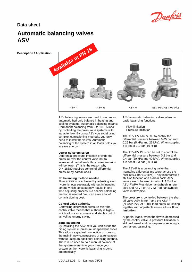
Automatic balancing valvesASV
ASV-I ASV-M ASV-P ASV-PV / ASV-PV Plus
ASV automatic balancing valves allow twobasic balancing functions:
- Flow limitation- Pressure limitation
The ASV-PV can be set to control thedifferential pressure between 0.05 bar and0.25 bar (5 kPa and 25 kPa). When suppliedit is set at 0.1 bar (10 kPa).
The ASV-PV Plus can be set to control thedifferential pressure between 0.2 bar and0.4 bar (20 kPa and 40 kPa). When suppliedit is set at 0.3 bar (30 kPa).
The ASV-P is a balancing valve thatmaintains differential pressure across theriser at 0.1 bar (10 kPa). They incorporate ashut-off function and a drain cock. ASVvalves are to be used in sets of: ASV-P orASV-PV/PV Plus (blue handwheel) in returnpipe and ASV-I or ASV-M (red handwheel)valve in flow pipe.
The pressure is controlled between the shutoff valve ASV-M (or I) and the ASV-P(or ASV-PV). At 100% load pressure limitingtogether with adjustable orifice allows flowlimitation.
At partial loads, when the flow is decreasedby the control valve, a pressure limitation isstill performed and consequently securing apermanent balancing.
Available in PN 16

2 VD.A1.T1.02 © Danfoss 05/03 SIBC
Data sheet Automatic balancing valves ASV
Description / Application(continued)
Fig 1. ASV in riser / heating
ASV-M ASV-M ASV-M
FV
ASV-P ASV-PASV-P
ASV valves are to be used in radiator heatingsystems to control the differential pressure inrisers. To limit the flow for every radiator, thethermostatic radiator valve with pre-settingfacilities (feature) is used together with aconstant pressure provided by the ASV, thusproviding balanced heat distribution.Alternatively the flow in the riser can belimited by using setting function of the ASV-I.
ASV valves are performing pressure controlnot only at design conditions (100 % load) butalso at all partial loads (to fulfill therequirements of DIN 18380 norms). Bycontrolling pressure at a partial load one canprevent noise problems on thermostaticradiator valves which often occur inunbalanced systems.
By installing the ASV sets you may divideyour heating system in pressure independentzones. This would allow a gradual connectionof zones/risers to the main in newconstructions or at renovation without the useof an additional balancing method. There isno need to perform a new commissioningevery time the system is changed as thehydronic balancing is done automatically.Controlling differential pressure over the risermeans also that the valve authority over thethermostatic radiator valves is high – whichallows an accurate and stable temperaturecontrol and saves energy.
ASV balancing valves are designed toguaranty a high quality of the automaticbalancing by:- a pressure released cone- an adapted membrane for every valve
dimension which provide constant qualityperformance for all sizes.
A 90° angle between all service features(shut-off, draining, setting, measuring) allowsan easy access under any installingcondition.
All the above-mentioned features andfunctions are realized in small build-indimensions so it is easy to install the ASValso under worst installing conditions.The ASV valves are packaged in styropor(EPS) which can be used for insulation attemperatures up to 80 °C. An insulation capis available as an accessory for insulation athigher temperatures (up to 120° C). The ASVvalves are supplied with an internal orexternal thread. (ASV-PV Plus only withinternal threads) If an external thread ischosen, a threaded or weld nipple can besupplied as an accessory.

SIBC VD.A1.T1.02 © Danfoss 05/03 3
Data sheet Automatic balancing valves ASV
Description / Application(continued)
Fig. 3 ASV with fan coil
ASV-I ASV-PV ASV-I ASV-PV
The ASV valves are to be used in systemswith fan coils, induction devices and air-heaters to secure an automatic hydronicbalance by the means of differential pressurecontrol in branches or at every coil. Constantdifferential pressure in combination with pre-set control valves i.e. ASV-I limits the flow.
By using automatic ASV valves you candivide your heating system in pressureindependent zones. This would allow gradualconnection of zones without additionalbalancing method used. There is no need toperform a new commissioning every time thesystem is changed because the hydronicbalance is done automatically.
ASV valves are to be used in floor heatingsystems. To limit the flow for every loopvalves or manifolds with an integrated flowlimiting or presetting should be used togetherwith a constant pressure provided by anASV-PV or an ASV-PV Plus. Alternatively theflow for the whole manifold can be limited byusing the setting function of the ASV-I.
The ASV-PV can control the differentialpressure between 0.05 and 0.25 bar (5 and25 kPa). If a higher pressure is needed, anASV-PV Plus which provides a pressurebetween 0.2 and 0.4 bar (20 and 40 kPa) canbe used. Due to its small dimensions the ASVautomatic balancing valves are easy to installin a wall mounted box for floor heatingmanifolds.
ASV-M
ASV-PV
CFD
CFE
TWA
CFE
RA5062
TP5000
RET
Fig. 2 ASV in manifold for floor heating system
The ASV valves are performing pressurecontrol not only at design conditions (100 %load) but also at all partial loads. Differentialpressure limitation provide that pressure overthe control valve will not increase at partialloads thus noise emission will be lower.Controlling differential pressure over controlvalve means that authority is high – whatallow accurate and stable control and to saveenergy. Due to small dimesions, it is easy toinstall the ASV also in worst installingcondition.
4 VD.A1.T1.02 © Danfoss 05/03 SIBC
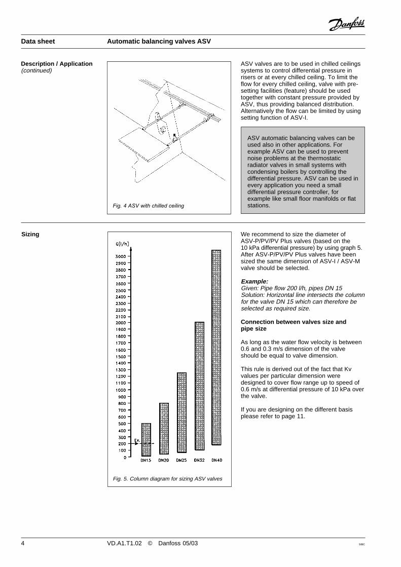
Fig. 5. Column diagram for sizing ASV valves
We recommend to size the diameter ofASV-P/PV/PV Plus valves (based on the10 kPa differential pressure) by using graph 5.After ASV-P/PV/PV Plus valves have beensized the same dimension of ASV-I / ASV-Mvalve should be selected.
Example:Given: Pipe flow 200 l/h, pipes DN 15Solution: Horizontal line intersects the columnfor the valve DN 15 which can therefore beselected as required size.
Connection between valves size andpipe size
As long as the water flow velocity is between0.6 and 0.3 m/s dimension of the valveshould be equal to valve dimension.
This rule is derived out of the fact that Kvvalues per particular dimension weredesigned to cover flow range up to speed of0.6 m/s at differential pressure of 10 kPa overthe valve.
If you are designing on the different basisplease refer to page 11.
Sizing
Data sheet Automatic balancing valves ASV
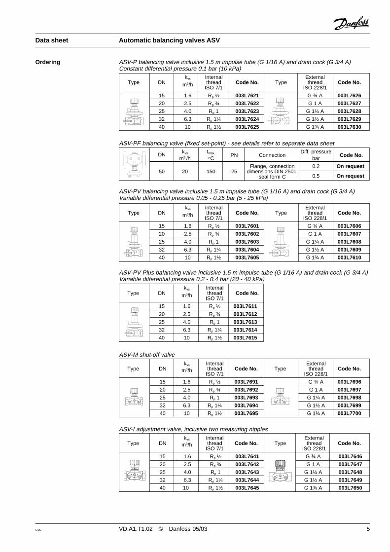
Fig. 4 ASV with chilled ceiling
ASV valves are to be used in chilled ceilingssystems to control differential pressure inrisers or at every chilled ceiling. To limit theflow for every chilled ceiling, valve with pre-setting facilities (feature) should be usedtogether with constant pressure provided byASV, thus providing balanced distribution.Alternatively the flow can be limited by usingsetting function of ASV-I.
Description / Application(continued)
ASV automatic balancing valves can beused also in other applications. Forexample ASV can be used to preventnoise problems at the thermostaticradiator valves in small systems withcondensing boilers by controlling thedifferential pressure. ASV can be used inevery application you need a smalldifferential pressure controller, forexample like small floor manifolds or flatstations.
SIBC VD.A1.T1.02 © Danfoss 05/03 5
Data sheet Automatic balancing valves ASV
Ordering
kvs Internal External Type DN m3/h thread Code No. Type thread Code No.
ISO 7/1 ISO 228/1
15 1.6 Rp ½ 003L7621 G ¾ A 003L7626
20 2.5 Rp ¾ 003L7622 G 1 A 003L7627
25 4.0 Rp 1 003L7623 G 1¼ A 003L7628
32 6.3 Rp 1¼ 003L7624 G 1½ A 003L7629
40 10 Rp 1½ 003L7625 G 1¾ A 003L7630
ASV-P balancing valve inclusive 1.5 m impulse tube (G 1/16 A) and drain cock (G 3/4 A)Constant differential pressure 0.1 bar (10 kPa)
DN kvs tmax. PN ConnectionDiff. pressure
Code No.m3 /h o C bar
Flange, connection 0.2 On request50 20 150 25 dimensions DIN 2501,
seal form C 0.5 On request
ASV-PF balancing valve (fixed set-point) - see details refer to separate data sheet
kvs Internal External Type DN m3/h thread Code No. Type thread Code No.
ISO 7/1 ISO 228/1
15 1.6 Rp ½ 003L7601 G ¾ A 003L7606
20 2.5 Rp ¾ 003L7602 G 1 A 003L7607
25 4.0 Rp 1 003L7603 G 1¼ A 003L7608
32 6.3 Rp 1¼ 003L7604 G 1½ A 003L7609
40 10 Rp 1½ 003L7605 G 1¾ A 003L7610
ASV-PV balancing valve inclusive 1.5 m impulse tube (G 1/16 A) and drain cock (G 3/4 A)Variable differential pressure 0.05 - 0.25 bar (5 - 25 kPa)
kvs InternalType DN m3/h thread Code No.
ISO 7/1
15 1.6 Rp ½ 003L7611
20 2.5 Rp ¾ 003L7612
25 4.0 Rp 1 003L7613
32 6.3 Rp 1¼ 003L7614
40 10 Rp 1½ 003L7615
ASV-PV Plus balancing valve inclusive 1.5 m impulse tube (G 1/16 A) and drain cock (G 3/4 A)Variable differential pressure 0.2 - 0.4 bar (20 - 40 kPa)
kvs Internal ExternalType DN m3/h thread Code No. Type thread Code No.
ISO 7/1 ISO 228/1
15 1.6 Rp ½ 003L7691 G ¾ A 003L7696
20 2.5 Rp ¾ 003L7692 G 1 A 003L7697
25 4.0 Rp 1 003L7693 G 1¼ A 003L7698
32 6.3 Rp 1¼ 003L7694 G 1½ A 003L7699
40 10 Rp 1½ 003L7695 G 1¾ A 003L7700
ASV-M shut-off valve
kvs Internal ExternalType DN m3/h thread Code No. Type thread Code No.
ISO 7/1 ISO 228/1
15 1.6 Rp ½ 003L7641 G ¾ A 003L7646
20 2.5 Rp ¾ 003L7642 G 1 A 003L7647
25 4.0 Rp 1 003L7643 G 1¼ A 003L7648
32 6.3 Rp 1¼ 003L7644 G 1½ A 003L7649
40 10 Rp 1½ 003L7645 G 1¾ A 003L7650
ASV-I adjustment valve, inclusive two measuring nipples

6 VD.A1.T1.02 © Danfoss 05/03 SIBC
Data sheet Automatic balancing valves ASV
Ordering (continued) Accessories and spare parts
Comments/connection Code No.
DN 15 003L8155
DN 20 003L8156
Shut-off knob for ASV DN 25 003L8157
(black) DN 32 003L8158
DN 40 003L8158
DN 15 003L8146
DN 20 003L8147
Shut-off knob for ASV-I DN 25 003L8148
(black) DN 32 003L8149
DN 40 003L8149
Differential pressure measuring for drain cock003L8143
connector
Drain cock for ASV-PV 003L8141
Two measuring nipples andfor ASV-I and ASV-M 003L8145
one locking plate
Impulse tube 1.5 m 003L8152
Impulse tube 5 m 003L8153
Nipple for connectingimpulse tube on Rp
1/16 - G 1/8 A 003L8150Danfoss type MV-FN
Nipple for connectingimpulse tube on other G 1/16 - R 1/4 003L8151valves
Nipple for connectingimpulse tube on other G 1/16 -
7/16 - 20 UNF - 2B 003L8176valves
O-ring for imp. tube 2,98 x 1,78 003L8175
Plug for impulse tube connection ASV-I/M G 1/16
003L8174
��
�
Max. pressure .........................16 bar (PN 16)Test pressure ....................................... 25 barDifferential pressure over thevalve .................. 0.1 - 1.5 bar (10 - 150 kPa)*Temperature ............................. -20 to 120 °C
* Please note that the maximum admissibledifferential pressure across the valve1.5 bar (150 kPa) should also not beexceeded with part load.
Technical data Material of parts in contact with water:Valve .................................................... BrassCone (ASV-P/PV/PV Plus) ........... DZR brassMembran ............................................. EPDMSpring ..................................... Stainless steel
SIBC VD.A1.T1.02 © Danfoss 05/03 7
Data sheet Automatic balancing valves ASV
Design
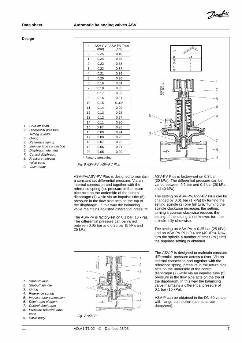
Fig. 6 ASV-PV, ASV-PV Plus
1. Shut-off knob2. Differential pressure
setting spindle3. O-ring4. Reference spring5. Impulse tube connection6. Diaphragm element7. Control diaphragm8. Pressure-relieved
valve cone9. Valve body
ASV-PV/ASV-PV Plus is designed to maintaina constant set differential pressure. Via aninternal connection and together with thereference spring (4), pressure in the returnpipe acts on the underside of the controldiaphragm (7) while via an impulse tube (5),pressure in the flow pipe acts on the top ofthe diaphragm. In this way the balancingvalve maintains adjusted differential pressure.
The ASV-PV is factory-set on 0.1 bar (10 kPa).The differential pressure can be variedbetween 0.05 bar and 0.25 bar (5 kPa and25 kPa).
1. Shut-off knob2. Shut-off spindle3. O-ring4. Reference spring5. Impulse tube connection6. Diaphragm element7. Control diaphragm8. Pressure-relieved valve
cone9. Valve body
The ASV-P is designed to maintain constantdifferential pressure across a riser. Via aninternal connection and together with thereference spring, pressure in the return pipeacts on the underside of the controldiaphragm (7) while via an impulse tube (5),pressure in the flow pipe acts on the top ofthe diaphragm. In this way the balancingvalve maintains a differential pressure of0.1 bar (10 kPa).
ASV-P can be obtained in the DN 50 versionwith flange connection (see separatedatasheet).
Fig. 7 ASV-P
ASV-PV Plus is factory-set on 0.3 bar(30 kPa). The differential pressure can bevaried between 0.2 bar and 0.4 bar (20 kPaand 40 kPa).
The setting on ASV-PV/ASV-PV Plus can bechanged by 0.01 bar (1 kPa) by turning thesetting spindle (2) one full turn. Turning thespindle clockwise increases the setting;turning it counter clockwise reduces thesetting. If the setting is not known, turn thespindle fully clockwise.
The setting on ASV-PV is 0.25 bar (25 kPa)and on ASV-PV Plus 0.4 bar (40 kPa). Nowturn the spindle a number of times (“n”) untilthe required setting is obtained.
DN
15 2.520 325 432 540 5
DANFOSSSEBCP.ALLENKEY.001.01
n ASV-PV ASV-PV Plus(bar) (bar)
0 0.25 0.40
1 0.24 0.39
2 0.23 0.38
3 0.22 0.37
4 0.21 0.36
5 0.20 0.35
6 0.19 0.34
7 0.18 0.33
8 0.17 0.32
9 0.16 0.31
10 0.15 0.30*
11 0.14 0.29
12 0.13 0.28
13 0.12 0.27
14 0.11 0.26
15 0.10* 0.25
16 0.09 0.24
17 0.08 0.23
18 0.07 0.22
19 0.06 0.21
20 0.05 0.20
* Factory presetting

8 VD.A1.T1.02 © Danfoss 05/03 SIBC
Data sheet Automatic balancing valves ASV
Design (continued)
ASV-M is designed to shut-off the pipe flow.ASV-M has a connection for an impulse tubeto ASV-P/ASV-PV and can be equipped withnipples for flow measuring.
Port A Port B
1. Shut-off knob2. Shut-off spindle3. Setting spindle4. Scale disc5. O-rings6. Valve cone7. Valve body
Fig. 8 ASV-I
1. Shut-off knob2. Shut-off spindle3. O-rings4. Valve cone5. Valve body
ASV-I incorporates a double cone able togive maximum stroke limitation, thusachieving flow limitation. It also incorporatesshut off function. ASV-I is equipped with thenipples for the flow measurement and aconnection for the ASV-P/ASV-PV impulsetube.
Use the following procedure to limit the flow:turn the valve knob fully counter clockwise toopen the valve. The mark on the knob willnow be opposite »0« on the scale. Turn thevalve knob clockwise to the required setting(e.g. for setting 2.2 the knob must be rotatedtwo full turns and then forward to »2« on the
Port A Port B
scale. Hold the knob to keep the setting (e.g.2.2) and using a hexagon socket key turn thespindle fully counter clockwise (until a stopcan be felt). Turn the valve knob fully counterclockwise so that the mark on the knob isopposite »0« on the scale. The valve is nowopen as many turns from the closed position(2.2) as indicated by the convertion fromrequired flow. To annul the setting, turn thehexagon socket key fully clockwise (until astop can be felt).
Remember, at the same time the knob mustbe held on its »0« setting.
DN
15 2.520 325 432 540 5
DANFOSSSEBCP.ALLENKEY.001.01
Fig. 9 ASV-M
SIBC VD.A1.T1.02 © Danfoss 05/03 9
Data sheet Automatic balancing valves ASV
Sizing
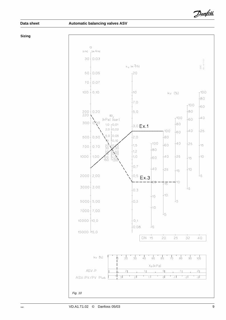
Fig. 10
10 VD.A1.T1.02 © Danfoss 05/03 SIBC
Data sheet Automatic balancing valves ASV
Sizing - design examples 1. Example
Given:Radiator system with thermostatic radiatorvalves with pre-setting function.Desired flow for the riser (Q): ............ 1500 l/hMinimal available pressurefor that riser (∆pa)................................. 70 kPaEstimated pressure drop over the riserat the desired flow (∆pr)................... 20 kPa
Wanted:- Valve type- Valve size
Since radiator valves has pre-setting functionASV-M is selected.
Since desired pressure drop over the riser is20 kPa ASV-PV is selected.
ASV-PV should control 20 kPa pressure overthe riser that means that 50 kPa out of 70 willbe disposed over two valves.
∆pp + ∆pm = ∆pa - ∆pr = 70 - 20 = 50 kPa
We presume that dimension DN 25 is theright dimension for this example (please mindthat both valves should be of the samedimension). As ASV-M DN 25 is to be fullyopen pressure drop is calculated by followingequation:
∆pm = 0.14 bar = 14 kPa
Or by reading from diagram (fig.14) asfollows:Draw horizontal line from 1.5 m3/h (~1500 l/h)trough the line that depicts dimension DN 25.From the intersection draw vertical line toread that pressure drop is 14 kPa.
Pressure drop over ASV-PV valve istherefore:
∆pp = (∆pa - ∆pr) - ∆pm =50 kPa - 14 kPa = 36 kPa
From diagram (fig. 10 - Ex. 1) we canestablish that DN 25 is the first dimension thatcan be used for this example by:
Drawing the line trough the point 1500 l/h onQ-line and 0.36 kPa on ∆pv -line to intersectpoint 2.5 m3/h on Kv-line. From this pointhorizontal line should be drawn until itintersects the first line that representsparticular valve dimension.
If in doubt regarding the valve size decisionshould be made according to following:
1. Smaller dimension should be selected toutilize valve to full extent.
2. Higher dimension should be selected tobe on the safe side when desired flow (Q)is higher tha specified, or when estimatedminimale available pressure is lower thanspecified (∆pa).
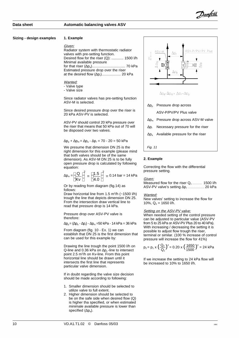
Fig. 11
∆pp Pressure drop across
ASV-P/PV/PV Plus valve
∆pm Pressure drop across ASV-M valve
∆pr Necessary pressure for the riser
∆pa Available pressure for the riser
2. Example
Correcting the flow with the differentialpressure setting.
Given:Measured flow for the riser Q1 ................ 1500 l/hASV-PV valve’s setting ∆pr ............................ 20 kPa
Wanted:New valves’ setting to increase the flow for10%, Q2 = 1650 l/h.
Setting on the ASV-PV valve:When needed setting of the control pressurecan be adjusted to particular value (ASV-PVfrom 5 to 25 kPa or ASV-PV Plus 20 to 40 kPa).With increasing / decreasing the setting it ispossible to adjust flow trough the riser,terminal or similar. (100 % increase of controlpressure will increase the flow for 41%)
p2 = p1 x ( Q2 )2 = 0.20 x ( 1650 )2
= 24 kPa Q1 1500
If we increase the setting to 24 kPa flow willbe increased to 10% to 1650 l/h.
=
=
22
4.01.5
KvQ

SIBC VD.A1.T1.02 © Danfoss 05/03 11
Fig. 12
∆ppv Pressure drop across ASV-PV valve
∆pi Pressure drop across ASV-I valve
∆po Pressure drop in the riser including ASV-I
∆pa Available pressure for the riser
∆pr Pressure drop in the riser excluding ASV-I
3. ExampleLimiting the flow with ASV-I valve
Given:Desired flow for the branch (Q): ......... 880 l/hASV-PV and ASV-I (DN 25)Setting on the ASV-PV valve (∆po) .... 10 kPaEstimated pressure drop over the riserat desired flow (∆pr) .................................................. 4 kPa
Required:Setting of the ASV-I valve to achieve desiredflow
Solution:When needed setting of the ASV-I can beadjusted to perform flow limitation function.ASV-I namely is inside the control loop of thepressure controller therefore adjusting ASV-Iwould result in adjusting flow limitation.(General rule is that 100 % increase of kvvalue will increase the flow for 100%)
At partial loads automatic balancing valve arein general throttling surplus pressure byclosing itself.
ASV-P, ASV-PV and ASV-PV Plus valves aredesigned to control differential pressureacross the riser by using compression spring.As spring compresses controlling pressureincreases and vice versa. In practise thismeans that controlling pressure is highest atvalve’s closing position and minimal at fullyopen position.
ASV-P, ASV-PV and ASV-PV Plus aredesigned that setting pressure is achieved at62.5 % of working stroke.
At desired flow pressure drop over the entirebranch is 4 kPa. Without using ASV-I flowtrough the branch at fully open control valvewill be 58% higher thus causing overflow(4 kPa allow 880 l/h, while 10 kPa allow1390 l/h). With adjusting the ASV-I DN 25 onvalue 90% kv value (3.6 m3/h) we will limit theflow to 880 l/h as desired.
This value is optained by followingcalculation:
∆pi = ∆po - ∆pr = 10 - 4 = 6 kPa
Kv = = = 3,6 m3/h
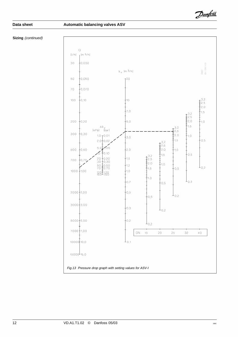
Or by reading from graph (fig. 13) by drawingthe line trough point 880 l/h on Q-line and6 kPa on ∆ppv line untill intersect the kv-line.From the point on kv-line (3.6 m3/h) drawhorizontal line to untill DN 25 line is intersectsat 2.4 setting.
Given:ASV-P & ASV-M (DN 25)Setting on the valve ∆pr ..................... 10 kPaAvailable pressurefor the riser ∆pa ........................................................ 40 kPaFlow (Q) ............................................. 220 l/h
Required:Controlled pressure at 220 l/h
Solution:Pressure drop across ASV-P is∆pp = ∆pa - ∆pr = 40 - 10 = 30 kPa
By drawing the line trough Q = 220 l/h and∆pp = 0.3 bar and horizontal line intersectcolumn of DN 25 at value 10% or bycalculating from eq.:
Kv = =0,4 m3/h, this is 10% of kvs value.
By reading from graph (fig.10 - Ex. 3) forASV-P valve controlled pressure is 2.6 kPahigher (P-band or Xp) then the setting, thuscontrolling 12.6 kPa.
Sizing - additional info forpartial load
Sizing - design examples(continued)
Data sheet Automatic balancing valves ASV
pvp∆Q
0,06
0,880
p∆Q
12 VD.A1.T1.02 © Danfoss 05/03 SIBC
Data sheet Automatic balancing valves ASV
Sizing (continued)
Fig.13 Pressure drop graph with setting values for ASV-I

SIBC VD.A1.T1.02 © Danfoss 05/03 13
Fig.14 Pressure drop over ASV-M valves
Data sheet Automatic balancing valves ASV
ASV-I is equipped with two measuring nipplesso that the differential pressure across thevalve can be measured using Danfossmeasuring equipment PFM 3000 or anyother measuring device. When the measuringequipment quick couplings are connected,the measuring nipples can be opened bygiving them a half-turn counter clockwise withan 8 mm open-ended spanner.
Using the pressure drop graph for ASV-I,fig. 13, the actual differential pressure acrossa fully open valve can be converted to actualflow.
After measurement, the nipples must beclosed again by turning them back clockwiseand disconnecting the quick-couplings. Note:When measuring sized flow, all radiatorvalves must be fully open (nominal flow).
Measurement of differential pressure (∆pr )across riser .Fit a measuring connector (Danfoss code no.003L8143) on the ASV-P/PV/PV Plusbalancing valve drain cock. Measurementsmust be taken between the measuring nippleat ASV-I/ASV-M valve port B and themeasuring connector on the draincock.
ASV-P, ASV-PV or ASV-PV Plus must beinstalled in the return pipe with flow in thedirection of the cast-in arrow. ASV-M andASV-I must be installed in the flow pipe, withflow in the direction of the cast-in arrow. Theimpulse tube must be installed betweenASV-M / I and ASV-P / PV / PV Plus.
Installation
Measurement of flow anddifferential pressure
The impulse tube must be flushed throughbefore installation. ASV-PV and ASV-I mustin addition be installed as determined byinstallation conditions
Max. test pressure ............................... 25 bar
When pressure testing the system you mustsecure that both sides of the membrane havethe same static pressure to prevent damageof the pressure controller. That means theimpulse tube must be connected and anyneedle valves must be open.
Pressure testing
Sizing (continued)
If ASV-P / PV or ASV-PV Plus is installed incombination with ASV-M both valves must beopen or closed (both valves must be in thesame position!). If ASV-PV or ASV-PV Plus isinstalled in combination with ASV-I bothvalves must be open.

14 VD.A1.T1.02 © Danfoss 05/03 SIBC
Data sheet Automatic balancing valves ASV
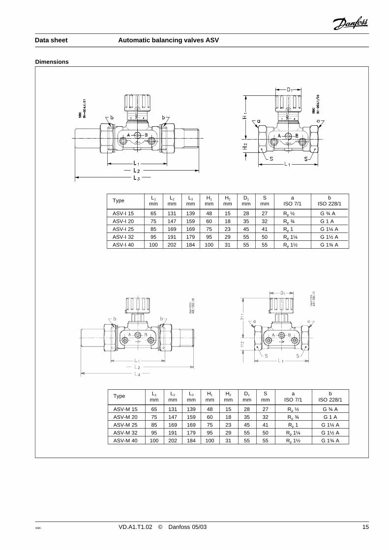
Dimensions
Type L1 L2 L3 H1 H2 D1 D2 S a b cmm mm mm mm mm mm mm mm ISO 7/1 ISO 228/1 ISO 228/1
ASV-P 15 65 131 139 82 15 28 61 27 Rp ½ G ¾ A
ASV-P 20 75 147 159 103 18 35 76 32 Rp ¾ G 1 A G ¾ AASV-P 25 85 169 169 132 23 45 98 41 Rp 1 G 1¼ A
ASV-P 32 95 191 179 165 29 55 122 50 Rp 1¼ G 1½ A
ASV-P 40 100 202 184 170 31 55 122 55 Rp 1½ G 1¾ A
Type L1 L2 L3 H1 H2 D1 D2 S a b cmm mm mm mm mm mm mm mm ISO 7/1 ISO 228/1 ISO 228/1
ASV-PV/PV Plus 15 65 131 139 102 15 28 61 27 Rp ½ G ¾ A
ASV-PV/PV Plus 20 75 147 159 128 18 35 76 32 Rp ¾ G 1 A G ¾ AASV-PV/PV Plus 25 85 169 169 163 23 45 98 41 Rp 1 G 1¼ A
ASV-PV/PV Plus 32 95 191 179 204 29 55 122 50 Rp 1¼ G 1½ A
ASV-PV/PV Plus 40 100 202 184 209 31 55 122 55 Rp 1½ G 1¾ A
SIBC VD.A1.T1.02 © Danfoss 05/03 15
Data sheet Automatic balancing valves ASV
Dimensions
Type L1 L2 L3 H1 H2 D1 S a bmm mm mm mm mm mm mm ISO 7/1 ISO 228/1
ASV-I 15 65 131 139 48 15 28 27 Rp ½ G ¾ A
ASV-I 20 75 147 159 60 18 35 32 Rp ¾ G 1 A
ASV-I 25 85 169 169 75 23 45 41 Rp 1 G 1¼ A
ASV-I 32 95 191 179 95 29 55 50 Rp 1¼ G 1½ A
ASV-I 40 100 202 184 100 31 55 55 Rp 1½ G 1¾ A
Type L1 L2 L3 H1 H2 D1 S a bmm mm mm mm mm mm mm ISO 7/1 ISO 228/1
ASV-M 15 65 131 139 48 15 28 27 Rp ½ G ¾ A
ASV-M 20 75 147 159 60 18 35 32 Rp ¾ G 1 A
ASV-M 25 85 169 169 75 23 45 41 Rp 1 G 1¼ A
ASV-M 32 95 191 179 95 29 55 50 Rp 1¼ G 1½ A
ASV-M 40 100 202 184 100 31 55 55 Rp 1½ G 1¾ A

16 VD.A1.T1.02 © Danfoss 05/03 SIBC
Data sheet Automatic balancing valves ASV
SIBC VD.A1.T1.02 © Danfoss 05/03 17
Description
Data sheet
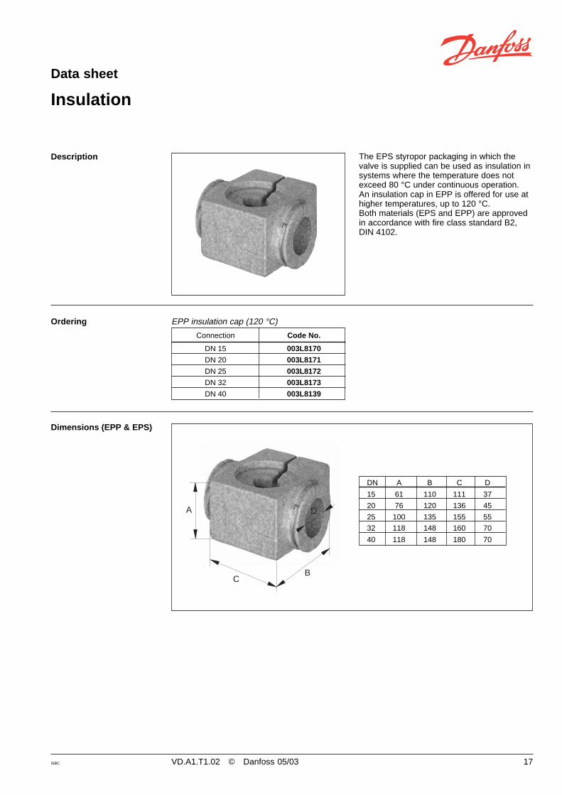
Insulation
The EPS styropor packaging in which thevalve is supplied can be used as insulation insystems where the temperature does notexceed 80 °C under continuous operation.An insulation cap in EPP is offered for use athigher temperatures, up to 120 °C.Both materials (EPS and EPP) are approvedin accordance with fire class standard B2,DIN 4102.
Connection Code No.
DN 15 003L8170
DN 20 003L8171
DN 25 003L8172
DN 32 003L8173
DN 40 003L8139
EPP insulation cap (120 °C)Ordering
Dimensions (EPP & EPS)
DN A B C D
15 61 110 111 37
20 76 120 136 45
25 100 135 155 55
32 118 148 160 70
40 118 148 180 70
A
CB
D

18 VD.A1.T1.02 © Danfoss 05/03 SIBC
Data sheet Automatic balancing valves ASV

SIBC VD.A1.T1.02 © Danfoss 05/03 19
Description
Data sheet
Fittings
For valves with external thread Danfossoffers threaded or welded nipples asaccessory. One nipple set consisting of twonipples, two union nuts and two seals.
MaterialsNut ........................................................ brassWeld nipple ............................................. steelThreaded nipple .................................... brass
1 nipple set consisting of two nipples, two union nuts and two seals
Connection Code No.
DN 15, G ¾ A 003N5070
Threaded nippleDN 20, G 1 A 003N5071
DN 25, G 1¼ A 003N5072
DN 32, G 1½ A 003N5073
DN 40, G 1¾ A 065F6060DN 15, G ¾ A 003N5090
Welded nippleDN 20, G 1 A 003N5091
DN 25, G 1¼ A 003N5092
DN 32, G 1½ A 003N5093
DN 40, G 1¾ A 065F6080
Ordering
20 VD.A1.T1.02 © Danfoss 05/03 SIBC
Data sheet Automatic balancing valves ASV
Danfoss A/SComfort DivisionHårupvænget 11HårupDK-8600 SilkeborgDenmarkTel.: +45 86 80 36 66Fax: +45 86 80 19 66
http://www.hydronicbalancing.com
Danfoss Trata d.o.o.Jožeta Jame 16, P.O.B. 48201210 Ljubljana - ŠentvidSloveniaTel.: +386 1/58 20 200Fax: + 386 1/51 99 824
http://www.danfoss-trata.si