investigation bismuth cuprates (bi2+xsr2-xcuo6)n (sr8cu6o16+y)€¦ · sharing cuo6 octahedra...
TRANSCRIPT

415-
HREM investigation of n = 4 members of the tubular bismuthcuprates (Bi2+xSr2-xCUO6)n (Sr8Cu6O16+y)
Bernadette Domengès(1), Maria Teresa Caldes(1), Maryvonne Hervieu(1), AmparoFuertes(2) and Bernard Raveau(1)
(1) Laboratoire de Cristallographie et Sciences des Matériaux, Bd. du Maréchal Juin, 14050 CaenCedex, France
(2) Institut de Ciencias de Materials de Barcelona (C.S.I.C.), Campus UAB-08193-Bellaterra,Barcelona, Spain
(Received June 28, 1992; accepted November 02, 1992)
Abstract. 2014 The HREM study of the fourth members of the tubular bismuth cuprates family,Bi4Sr8Cu5O19, Bi4Sr7LaCu5O19.5 and Bi4Sr8Cu3Fe2O20 is performed. The microstructure of mostcrystals is characterized by domains showing a regular atom stacking. A new monoclinic-5 tubularstructure is identified twice in large domains.
Microsc. MicroanaL Microstruct. OCTOBER 1992, PAGE 415
Classification
Physics Abstracts61.16D
1. Introduction.
After the observation of superconductivity in the Bi-Sr-Cu-0 system [1], the exploration of thelatter has shown its extraordinarily rich chemistry. Besides the 2201 modulated oxides, supercon-ducting or not [2-4], a 2201-monoclinic phase, called collapsed 2201 [5] has also been isolated.The discovery of the orthorhombic oxide B4SrsCuS019 [6], with a tunnel structure has openedthe route to the research of a large series of cuprates. In fact this oxide represents the membern = 4 of the large structural family (Bi2+xSr2-xCU06)n (Sr8Cu6O16+y), called orthorhombictubular phases [7], for which numerous domains and boundaries were evidenced by high resolu-tion electron microscopy [8]. Besides these numerous oxides a new form of the seventh memberof the above family, but with a monoclinic symmetry was isolated [9]. The X-ray and neutrondiffraction powder studies of the n = 4 members of the tubular phases, Bi4Sr8Cu5O19+y [6],Bi4Sr8-xLaxCu5O19+y [10] and Bi4SrSCu3Fe2019+y [11] let appear, in spite of their great similar-ities, some structural differences between each compound. We report here on the high resolutionelectron microscopy investigation of these n = 4 tubular phases.
Article available at http://mmm.edpsciences.org or http://dx.doi.org/10.1051/mmm:0199200305041500

416
2. Expérimental.
The cuprates with nominal compositions Bi4SrgCu50i9, Bi4Sr7LaCu5O19.5 and Bi4SrgCu3Fe202owere synthesized according to the procedure previously reported [7, 10, 12].
For electron microscopy study, the samples were softly ground in n-butanol and deposited ona holey carbon coated copper grid. The electron diffraction work was performed on JEM 200CXequipped with a top-entry (± 10°) goniometer and an objective lens of spherical aberration con-stant Cs = 0.8 mm. Image calculations were performed using the multislice method of EMS pro-gram [13].
3. Structural recalls.
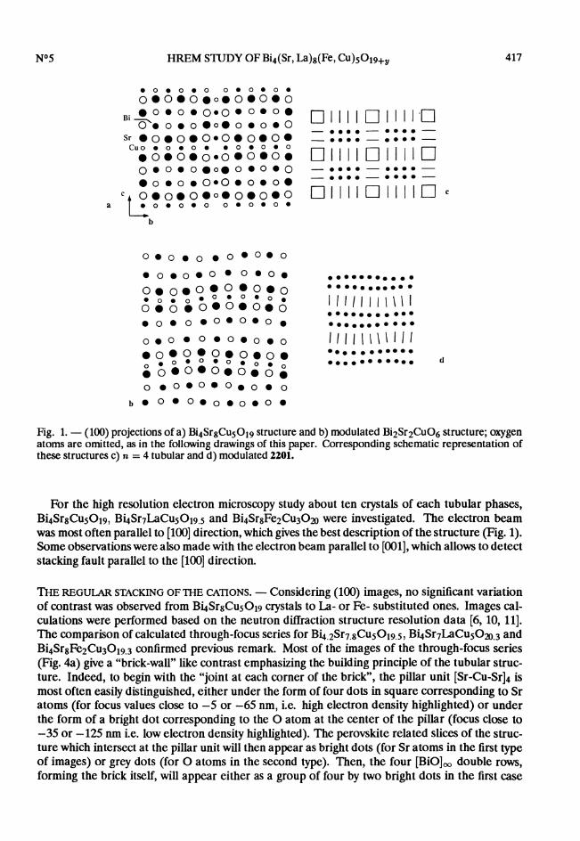
The structure of the orthorhombic tubular phase, fourth member of the family (Bi2+xSr2-xCu206)n (Sr8Cu6O16+y) (Fig. la) derives from the 2201-Bi2Sr2Cu06+6 modulated phase (Fig. 1b)by the intergrowth with [Sr8SCu6O16+y] perovskite related slices perpendicularly to the copperlayers of the 2201-type structure. In fact these Bi4SrgCu50i9 orthorhombic tubular phases con-sist of 2201-type slices, which are four Cu06 octahedron wide along b, i.e. involve four [BiO]~double rows running along a (Fig. la). Such slices can be formulated [(Bi2Sr2CuO6)4]~ in agree-ment with their similarity with the Bi2Sr2Cu06-type structure. The association of these quadruple2201-type slices with the SrgCu6016 slices prevents the modulation of the structure contrary to theBi2Sr2Cu06 structure in which one observes a waving of the [BiO]~ layers. In order to make eas-ier the discussion of the relationships and defects between the different phases of the system, wecan use a schematic representation of the structure omitting oxygen atoms (Fig. le), in which ver-tical or horizontal bars represent the Sr-Cu-Sr sticks of the CU06 octahedra, large dots correspondto Bi of the [BiO]~ rows, and squares correspond to the crossing of [Sr8Cu6O16+y]~ slices withthe copper layers, forming the square pillar unit [Sr-Cu-Sr]4 where copper may exhibit a five-foldor four-fold coordination; in the case of the modulated 2201 structure, one only observes layersof undulating vertical bars corresponding, to the single octahedral copper layers, alternating withundulating layers of double dots corresponding to the double [BiO]~ layers (Fig. Id). Thus, inthis representation, the different n-members of the orthorhombic tubular phases are character-ized by the size of Bi block represented by n x 2 large dots or by the number n of vertical barswhich are observed between two successive squares.
Besides the orthorhombic tubular phases, there exist monoclinic tubular cuprates which canbe deduced from the orthorhombic one by translating a copper layer of about 2.7 A. This isthe case of the n = 7 monoclinic member [9] whose structural model (Fig. 2a) differs from theorthorhombic one (Fig. 2b) by the nature of the [Sr8Cu6O16-y]~ slice which do not involve corner-sharing Cu06 octahedra but double rows of corner-sharing CuO5 pyramids (Fig. 2a) or edge-sharing CuO6 octahedra running along a. The schematic representation of such a monoclinicn = 7 structure is given in figure 2c.
4. Results and discussion.
The electron diffraction study of La- and Fe- substituted samples agreed with the n = 4 tubularphase - i.e. space group Bbab with a 0.54 nm, b N 3.4 nm, c ~ 2.4 nm (Fig. 3). No specialphenomenon could be related to substitution of La for Sr or Fe for Cu, in agreement with thestructure resolution work [6,10 11]. E.D. pattern with splitted dots forming arcs were often ob-served and could be related to misoriented domains, the corresponding images showing Moirepatterns at the junction and/or superimposition of the domains.
417
Fig. 1. - (100) projections of a) Bi4SrgCu5019 structure and b) modulated Bi2Sr2Cu06 structure; oxygenatoms are omitted, as in the following drawings of this paper. Corresponding schematic representation ofthese structures c) n = 4 tubular and d) modulated 2201.
For the high resolution electron microscopy study about ten crystals of each tubular phases,Bi4SrsCu50i9, Bi4Sr7LaCu50i9 5 and Bi4SrgFe2Cu302o were investigated. The electron beamwas most often parallel to [100] direction, which gives the best description of the structure (Fig. 1).Some observations were also made with the electron beam parallel to [001], which allows to detectstacking fault parallel to the [100] direction.
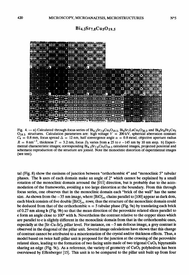
THE REGULAR STACKING OFTHE CATIONS. - Considering (100) images, no significant variationof contrast was observed from Bi4SrgCu50i9 crystals to La- or Fe- substituted ones. Images cal-culations were performed based on the neutron diffraction structure resolution data [6, 10, 11].The comparison of calculated through-focus series for Bi4.2Sr7.8Cu5O19.5, Bi4Sr7LaCu5O20.3 andBi4SrsFe2Cu3019.3 confirmed previous remark. Most of the images of the through-focus series(Fig. 4a) give a "brick-wall" like contrast emphasizing the building principle of the tubular struc-ture. Indeed, to begin with the "joint at each corner of the brick", the pillar unit [Sr-Cu-Sr]4 ismost often easily distinguished, either under the form of four dots in square corresponding to Sratoms (for focus values close to -5 or -65 nm, i.e. high electron density highlighted) or underthe form of a bright dot corresponding to the 0 atom at the center of the pillar (focus close to-35 or -125 nm i.e. low electron density highlighted). The perovskite related slices of the struc-ture which intersect at the pillar unit will then appear as bright dots (for Sr atoms in the first typeof images) or grey dots (for 0 atoms in the second type). Then, the four [BiO]~ double rows,forming the brick itself, will appear either as a group of four by two bright dots in the first case

418
Fig. 2 - (100) projection of perovskite related slice in a) monoclinic n = 7 tubular phase and b) or-thorhombic tubular phase. c) schematic representation of monoclinic n = 7 tubular structure.
or very dark dots in the second one. The calculated series fit well with expérimental images. Fig-ure 4b gives some characteristic experimental images of this n = 4 member. For -5 nm focusvalue, the brighter dots correspond to Sr atoms of the perovskite related slices, those of the pil-lar unit [Sr-Cu-Sr]4 being distinguished; they constitute the "cement" of the brick wall. [BiO]~rows appear as group of four by two slightly greyier dots. For -35 nm focus value, the center ofthe pillar unit [Sr-Cu-Sr]4 appears as very bright dot, oxygen atoms of the perovskite related sliceare slightly less bright and [BiO]~ rows are very dark. The image contrast is very sensitive to aslight misorientation of the optical axis of the objective lens which can lead to a dissymmetry ofthe contrast as observed on given Bi4SrsFe2Cu3019.3 image of figure 4b. Image calculation basedon a slightly tilted beam allowed to confirm this fact - calculated images with a beam tilting closeto 1 mrad and parallel to c are in good agreement with the observed ones.
It is worth pointing out that most of the crystal images show an even contrast, characteristicof the regular stacking of the cations of the n = 4 orthorhombic tubular structure, though amonoclinic distortion was observed on HREM images of some crystals (Fig. 4b). This distortioncould also be measured on the corresponding E.D. patterns. It appeared to be in the range 0.5°- 10 and could not be related to a main structural change, E.D. dot intensity and image contrastbeing left characteristic of the n = 4 tubular phase. Furthermore, this phenomenon was moreoften encountered during HREM study in the JEM 200 CX (high voltage : 200 kV) than fromE.D. investigation on the JEM 120 CX (high voltage 120 kV) especially Bi4SrSCuS019 crystalsshowed a relative stability under the electron beam. This monoclinic distortion, which origin

419
Fig. 3. - Characteristic E.D. patterns of n = 4 tubular phase, showing the following existence conditionsof Bbab space group : Okl, k = 2n (1 = 2n) ; hO/, h = 2n (1 = 2n) ; hk0, k=2n (h = 2n); hkh, no condition.
has no relation with the monoclinic tubular phase structure, may be due to a relaxation of theorthorhombic crystal framework under the electron beam.
5. Extended defects.
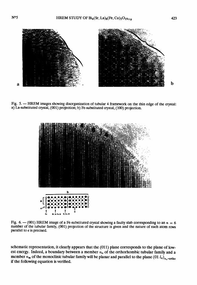
In a different way, the relaxation of the framework may lead to a disordering of the cation stack-ing, which is associated with a disappearance of the square pillar unit [Sr-Cu-Sr]4 as shown fromfigure 5.The intergrowth defects are very rare. The only intergrowth defect was observed in a Bi4Sr8Fe2
CU3019.3crystal as shown from the (001) HREM image (Fig. 6). On regular areas of the crystal,five rows of bright dots alternate with two rows of grey dots. The group of five rows can be as-similated to the low electron density zone - i.e. oxygen atoms of the basal plane of the Cu06octahedra of the (Bi2Sr2Cu6)4 units - as observed on similar materials viewed along this direction[14]. The faulty slab is made of seven rows of bright dots. It can thus be interpreted as the (001)projection of a (Bi2Sr2Cu06)6 unit, i.e. one slab of a n = 6 member of the orthorhombic tubularphase family. Indeed, the measured width of this slab, close to 2.25 nm corresponds to the b/2parameter of the n = 6 member.
Another type of extended defects, deals with the appearance in the n = 4 orthorhombic tubularmatrix of domains identified as n = 5 monoclinic tubular phase. Such domains are shown on themedium magnification images of figure 7 for Bi4SrgCus019 and Bi4Sr7LaCu50i9 5 crystals; the ar-ray parameters were measured as 1.92 x 1.29 nm2,a =100°, close to the theoretical parameters ofthe monoclinic n = 5 tubular phase ; b axes of each domain are almost parallel and c axes makean angle of 10°. One recognizes the brick wall-like contrast characteristic of the orthorhombicand monoclinic tubular phases. The enlarged (100) HREM images of B4Sr7LaCus019.5 crys-
420
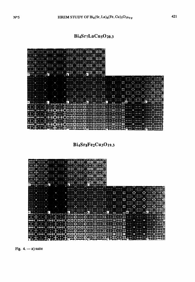
Fig. 4. - a) Calculated through-focus series of Bi4.2Sr7.8Cu5O19.5, Bi4Sr7LaCu5O20.3 and Bi4Sr8Fe2CU3019.3 structures. Calculation parameters are: high voltage V = 200 kV, spherical aberration constantCs = 0.8 mm, focus spread 0 = 12 nm, half convergence angle a = 0.8 mrad, objective aperture radiusR = 8 nm-1, thickness T = 3.2 nm, focus Df varies from a 25 to r -145 nm by 10 nm step. b) Experi-mental characteristic images; corresponding Bi4.2Sr7.8Cu5O19.5 calculated images, projected potential andschematic reproduction of the structure are joined. Note the monoclinic distortion of experimental images(see text).
tal (Fig. 8) show the easiness of junction between "orthorhombic 4" and "monoclinic 5" tubularphases. The b axes of each domain make an angle of 2° which cannot be explained by a smallrotation of the monoclinic domain arround the [011] direction, but is probably due to the acco-modation of the frameworks, avoiding a too large distortion at the boundary. From this throughfocus series, one observes that in the monoclinic domain each "brick of the wall" has the samesize. As shown from the -35 nm image, where [BiO]~ chains parallel to [100] appear as dark dots,each block consists of five double [BiO]~ rows; thus the structure of the monoclinic domain couldbe deduced from that of the orthorhombic n = 5 tubular phase (Fig. 9a) by translating each brickof 0.27 nm along b (Fig. 9b) so that the mean direction of the perovskite related slices parallel toc form an angle close to 1000 with b. Nevertheless the contrast relative to the copper slices whichare parallel to c is slightly différent in the monoclinic domain from that in the orthorhombic ones,especially at the [Sr-Cu-Sr]4 pillar level. For instance, on -5 nm defocus image, a grey contrast isobserved in the diagonal of the pillar unit. Several image calculations have shown that this changeof contrast cannot be attributed to a misorientation of the crystal and/or thickness effects. Thus, amodel based on twice half-pillar unit is proposed for the junction at the crossing of the perovskiterelated slices, leading to the formation of two facing units made of two trigonal CuO5 bipyramidssharing an edge (Fig. 9c). As a reference, the variety of geometry of CuOs polyhedron has beenoverviewed by Effenberger [15]. This unit is to be compared to the pillar unit built up from four
421
Fig. 4. - a) suite

422
Fig. 4. - b) suite
trigonal CU05 bipyramids sharing an edge in the orthorhombic tubular phase (Fig. 2b) or to thatin the n = 7 monoclinic tubular phase [9] and in the defect proposed by Matsui et al. [16] wherethe pillar unit remains unchanged and two trigonal CU05 corner-sharing bipyramids or two edge-sharing CU06 octahedra, depending on oxygen content, are formed at the [Sr-Cu-Sr]2 unit level(Fig. 2a). Thus, a boundary parallel to (011) plane of orthorhombic tubular 4 structure betweenan orthorhombic-4 and a monoclinic-5 domains can be proposed (Fig. IDa). Considering this
423
Fig. 5. - HREM images showing disorganization of tubular 4 framework on the thin edge of the crystal:a) La-substituted crystal, (001) projection; b) Fe-substituted crystal, (100) projection.
Fig. 6. - (001) HREM image of a Fe-substituted crystal showing a faulty slab corresponding to an n = 6number of the tubular family, (001) projection of the structure is given and the nature of each atom rowsparallel to c is precised.
schematic representation, it clearly appears that the (011) plane corresponds to the plane of low-est energy. Indeed, a boundary between a member no of the orthorhombic tubular family and amcmber nm of the monoclinic tubular family will be planar and parallel to the plane (01 lo)no-orthoif the following equation is verified.

424
Fig. 7. - Medium magnification (100) HREM images showing monoclinic domains, a) Bi4SrgCu5019 andb) La-substituted crystals. A planar boundary (B) is observed between monoclinic (M) and orthorhombic(0) domains.
Lo and Lm are the length of a "brick" of each domain i.e.
The term s ap2 2 measures the shifting parallel to bm from one "brick" row to the other m themonoclinic domain. Most often s = ±1 but some examples of higher shifting were observed asdefects (7). Equations (i) becomes:
This means that (lm-lo) -,f2- must be zero, thus 1m = 10 = 1. Then,

425
Fig. 8. - Enlarged HREM images of the experimental through-focus series of the edge of previous La-substituted crystal showing the planar boundary (B) between monoclinic (M) and orthorhombic tubular 4(0) domains; b and c axes of orthorhombic tubular 4 structure are drawn.
With s = ±1, 1 must be equal to 1, thus (ii) becomes : no = nm :i: 1.Consequently a planar boundary can only be obtained between one orthorhombic and one
monoclinic domains of two adjacent members e.g. 4-5 and the boundary plane will be (011)ortho.

426
Fig. 9. - a) Schematic representation of orthorhombic tubular 5 structure. b) Schematic representation ofthe proposed model for monoclinic tubular 5 structure. c) Detailed drawing showing the polyhedra involvedat the crossing of perovskite related slices in previous model.
Figure lOb gives an example of planar boundary between an no = 6 orthorhombic domain andnm = 5 monoclinic one, with s = -1.
Another interesting type of defect deals with the intergrowth between tubular phases and mod-ulated 2201. It was observed in Fe-substituted samples. The first example is given in figure 11.The medium resolution image shows two domains : the first one exhibits the usual "brick wall"contrast of the n = 4 tubular phase, the second one exhibits a modulated contrast typical of the2201 modulated phase, the contrast symmetry being orthorhombic body centered, which indicatesa q value close to 4, in agreement with previous studies of the Fe-substituted Bi2Sr2Cul-xFexOyphase. The SAED pattern of both domains allowed the qb vector of modulated area to be mea-sured : qb ~ 3.9. This value is slightly smaller than that observed in Bi2Sr2Cuo.5Feo.50y [17]. It
may thus mean that this modulated domain is Fe-richer, since the limit of the solid solution for-mation was determined as x = 0.6 ± 0.1 for Bi2Sr2Cul-xFexOy prepared in air [18]. The domainboundary is parallel to (001) and appears located at the perovskite related slice level. Indeed, the

427
Fig. 10. - Schematic representation of neighboring orthorhombic and monoclinic domains: a) orthorhom-bic tubular 4 and monoclinic tubular 5, no = 4, nm = 5, s = 1 ; b) orthorhombic tubular 6 and monoclinictubular 5, no = 6, nm = 5, s = -1.
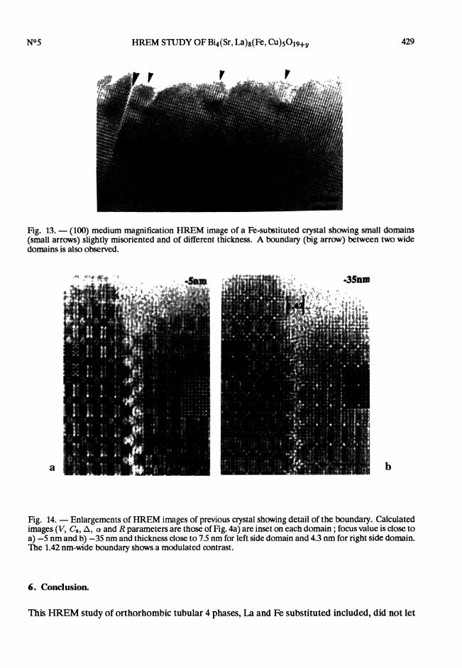
model of figure 12 shows the easiness of junction between both frameworks.The second example shows an n = 4 Fe-substituted crystal which exhibits many small domains,
slightly misoriented, leading to strong variation of the contrast from one to the other (Fig. 13).This low magnification image shows that the crystal is built up of two main domains translatedparallely to b, i.e. with a domain boundary parallel to b. Enlargement of high resolution imagesof the boundary (Fig. 14) on a thin edge of the crystal allows its structure to be analysed : theboundary width - measured pillar to pillar (Fig. 14) is around 1.42 ± 0.06 nm, the translationvector of one domain to the other being 1/5 (btub4). The analysis of contrast of the through focusseries and geometrical considerations suggest that this boundary is made of two rock-salt layers,Le. three [(Bi, Sr)O]~ rows (Fig. 15) which are probablywaving in a similarway to those observedin the 2201 modulated structure.

428
Fig. 11. - (100) medium resolution image and corresponding SAED pattern of a Fe-substituted crystalshowing one orthorhombic tubular 4 domain (0) and one modulated 2201 domain (M) sharing a planarboundary parallel to (001). On E.D. drawing, dots correspond to (100) tubular pattern and stars to modulated2201 one.
Fig. 12. - Schematic representation showing the easiness of junction between an orthorhombic tubulardomain (0) and a modulated 2201 one (M) with a (001) planar boundary.
429
Fig. 13. - (100) medium magnification HREM image of a Fe-substituted crystal showing small domains(small arrows) slightly misoriented and of different thickness. A boundary (big arrow) between two widedomains is also observed.
Fig. 14. - Enlargements of HREM images of previous crystal showing detail of the boundary. Calculatedimages (V, Cs, A, 03B1 and R parameters are those of Fig. 4a) are inset on each domain ; focus value is close toa) -5 nm and b) -35 nm and thickness close to 7.5 nm for left side domain and 4.3 nm for right side domain.The 1.42 nm-wide boundary shows a modulated contrast.
6. Conclusion.
This HREM study of orthorhombic tubular 4 phases, La and Fe substituted included, did not let

430
Fig. 15. - Schematic representation of model for previous boundary based on three waving [(Bi, Sr)O]~rows.
appear any peculiar behavior related to the La or Fe substitution. Under a structural point of view,two main defects were observed. A new monoclinic form of tubular structure was observed twiceon large domains. It was identified as the monoclinic n = 5 member of the tubular family. Theclose structural relationships between the tubular framework and the 2201 modulated one wasemphasized by an observed defect on Fe-substituted crystals. It corresponds to an orthorhombictubular domain sharing with a 2201 modulated one a planar boundary parallel to (010). Besidesthese defects, most crystals show domains with an even contrast, characteristic of a regular cationstacking with almost no intergrowth defect with other member of the family. This result do agreewith the classical behavior of structures based on the intergrowth of two structural units, one unitbeing characterized by a variable width : small members usually appear very regular to be opposedto high members which show many intergrowth defects [8].
References
[1] MICHEL C., HERVIEU M., BOREL M.M., GRANDIN A., DESLANDES F., PROVOST J. and RAVEAU B., Z.Phys. B 68 (1987) 421.
[2] ROTH R.S., PAWN C.J. and BENDERSKY I.A., J. Mater. Res. 5 (1990) 46.[3] IKEDA Y., ITO H., SHIMOMURA S., OUE Y., INABA K., IROI Z. and TAKANO M., Physica C 159 (1989)
93.
[4] CHAKOUMAKOS B.C., EBEY P.S., SALES B.C. and SONDUS E., J. Mater. Res. 4 (1991) 767.[5] HIROI Z., IKEDA Y., TAKANO M. and BANDO Y., J. Mater. Res. 6 (1991) 435.[6] a) FUERTES A., MIRATVILLES C., GONZALEZ-CALBET J., VALLET-REGI M., OBRADORS X.,
RODRIGUEZ-CARJAVAL J., Physica C 157 (1989) 529.b) CALDES M.T., NAVARRO J.M., FONTCUBERTA J., CASAÑ N., OBRADORS X., RODRIGUEZ J.,
GONZALEZ-CALBET J.M., FUERTES A., MIRATVILLES C., Chem. Mater. 3 (1991) 844.[7] CALDES M.T, HERVIEU M., RAVEAU B., FUERTES A., J. Solid State Chem. 97 (1992) 48[8] CALDES M.T, HERVIEU M., RAVEAU B., FUERTES A., J. Solid State Chem. 98 (1992) 301.

431
[9] CALDES M.T, HERVIEU M., RAVEAU B., FUERTES A. J. Solid State Chem. 98 (1992) 48.[10] CALDES M.T, FUERTES A., GOMEZ P., OBRADORS X., RODRIGUEZ J., Physica C 185-189 (1992) 681.[11] CALDES M.T, Ph. D., University of Valencia (1992).[12] CALDES M.T, FUERTES A., BRUNA L.L., OBRADORS X., FONTCUBERTA J., MARTINEZ B., PEREZ F., J.
Appl. Phys. 70 (1991) 6184.[13] STADELMANN P.A., Ultramicroscopy 21 (1987) 131.[14] HEWAT E., J. Micros. Spectrosc. Electron. 13 (1988) 297.[15] EFFENBERGER H., J. Solid State Chem. 73 (1988) 118.[16] MATSUI Y., TAKEMAWA S., KISHIO K., UMEZONO A., NAKAMURA S., TSURUTA C. and IBE K., Mat.
Trans. JIM 31 (1990) 595.[17] TARASCON J.M., MICELI P.F., BARBOUX P., HWANG D.M., HULL G.W, GIROUD M., GREENE L.H., LE
PAGE Y., MC KINNAN W.R., TSELEPSIS E., PLEIZIER G., EIBSCHUTZ M., NEUMAN D.A. and RHYNEJ.J., Phys. Rev. B 39 (1989) 11587.
[18] TARASCON J.M., LE PAGE Y., MC KINNAN W.R., RAMESH R., EIBSCHUTZ M., TSELEPSIS E., WANG E.and HULL G.W., Physica C 167 (1990) 20.